OWNER’S MANUAL - ZigBoat
2
eng Green dot: The sensor is working properly Red dot: The sensor is not able to connect to the Gateway: • Please check the battery status; • Check to ensure the correct serial number has been entered into the APP. • In case of a weak or a bad signal, relocate the battery sensor. “OK”: The battery power bank voltage is above the fixed threshold “LOW”: The battery power bank voltage is below the fixed threshold and, if the gateway is connected to internet you will receive a push notification on the APP. 9. When the red LED stops flashing, the ZigBoat™ Battery Sensor has successfully joined the ZigBoat™ network. To check the correct configuration, select the Overview tab of the ZigBoat™ App. (fig. 6) Resetting Resetting is needed if you want to connect your ZigBoat™ Battery Sensor to another gateway or if you need to perform a factory reset to eliminate abnormal behavior. The reset button is marked with the small ring on the front of the sensor. STEPS FOR RESETTING 1. Open the casing of the device by pushing the fastening on top of the device to remove the front panel from the back cover. 2. Remove the batteries (2xAAA) and reinsert the batteries 3. Press and hold down the reset button for approximately 8-10 seconds. The button has to be pushed within one minute after inserting the batteries. 4. When the red light starts flashing every second, the reset process has been successfully implemented. Mounting • Place the sensor indoors at a temperature between 0-50°C. • Connect the red wire (+) to the positive pole of the battery power bank. • Connect the black wire (-) to the negative pole of the battery power bank. IMPORTANT: Use one battery sensor for each battery power bank you want to monitor Version 1.0 OWNER’S MANUAL Fig. 1 Fig. 2 Fig.5/A Fig.5/B Fig. 3 5. Insert the enclosed batteries (2xAAA) into the sensor making sure to observe the correct polarity. 6. Close the casing. 7. The ZigBoat™ Battery Sensor will now start searching for the ZigBoat™ network to join. 8. While the ZigBoat™ Battery Sensor is searching for the ZigBoat™ network to join, the red light on the sensor will flash. 4. The Battery Sensor is set by default to 12V mode. To switch to 24V mode, please move the switch as indicated in the sticker placed in the device (fig. 5/A and 5/B). 3. You can change the device name by selecting “Name” (fig. 4). Then, press the “Add Device” button. Battery Sensor code: ZB201 • When removing sensor battery covers, remember that electrostatic discharge can damage electronic components inside. • Always mount indoors. • Do not remove the product label as it contains important information. Product description The ZigBoat™ Battery Sensor monitors the battery power bank voltage and, if it drops below a fixed threshold sends you push notifications. Thanks to the switch you can use 12V or 24V battery power bank. NOTE: 12V mode threshold: 11.6V (± 0.3V) 24V mode threshold: 23.1V (± 0.3V) Precautions Adding the sensor to the Gateway NOTE: Make sure the gateway is turned on and configured correctly. For more details, please see the gateway installation manual. 1. Open the Zigboat APP, select the Gateway in the ZB Gateways menu and wait a few seconds. Then, select the “menu” button on the top right (fig. 1). Select “Device list” (fig. 2). Add the sensor by entering the serial number which is on the sensor’s label (fig. 3). 2. To locate the serial number of the sensor, remove the front cover by pressing the tab on top. OK Battery Sensor Battery #1 12V 24V 12V 24V Fig. 4 Fig. 6 + + - - Battery Sensor installation manual.indd 1 19/04/18 11:10
Transcript of OWNER’S MANUAL - ZigBoat
eng
Green dot: The sensor is working properly
Red dot: The sensor is not able to connect to the
Gateway:
• Please check the battery status;
• Check to ensure the correct serial number has
been entered into the APP.
• In case of a weak or a bad signal, relocate the
battery sensor.
“OK”: The battery power bank voltage is above
the fixed threshold
“LOW”: The battery power bank voltage is
below the fixed threshold and, if the gateway
is connected to internet you will receive a push
notification on the APP.
9. When the red LED stops flashing, the
ZigBoat™ Battery Sensor has successfully
joinedtheZigBoat™network.
Tocheckthecorrectconfiguration,selectthe
OverviewtaboftheZigBoat™App.(fig.6)Resetting
Resetting is needed if you want to connect
your ZigBoat™ Battery Sensor to another
gateway or if you need to perform a factory
resettoeliminateabnormalbehavior.
Theresetbuttonismarkedwiththesmallring
onthefrontofthesensor.
STEPS FOR RESETTING
1. Open the casing of the device by pushing
thefasteningontopofthedevicetoremove
thefrontpanelfromthebackcover.
2. Removethebatteries(2xAAA)andreinsert
thebatteries
3. Press and hold down the reset button for
approximately 8-10 seconds. The button
has to be pushed within one minute after
insertingthebatteries.
4. When the red light starts flashing every
second, the reset process has been
successfullyimplemented.
Mounting
• Place the sensor indoors at a temperature
between0-50°C.
• Connecttheredwire(+)tothepositivepole
ofthebatterypowerbank.
• Connect the black wire (-) to the negative
poleofthebatterypowerbank.
IMPORTANT:Useonebatterysensorforeach
batterypowerbankyouwanttomonitor
Version1.0
OWNER’S MANUAL
Fig
. 1Fi
g. 2
Fig
.5/A
Fig
.5/B
Fig
. 3
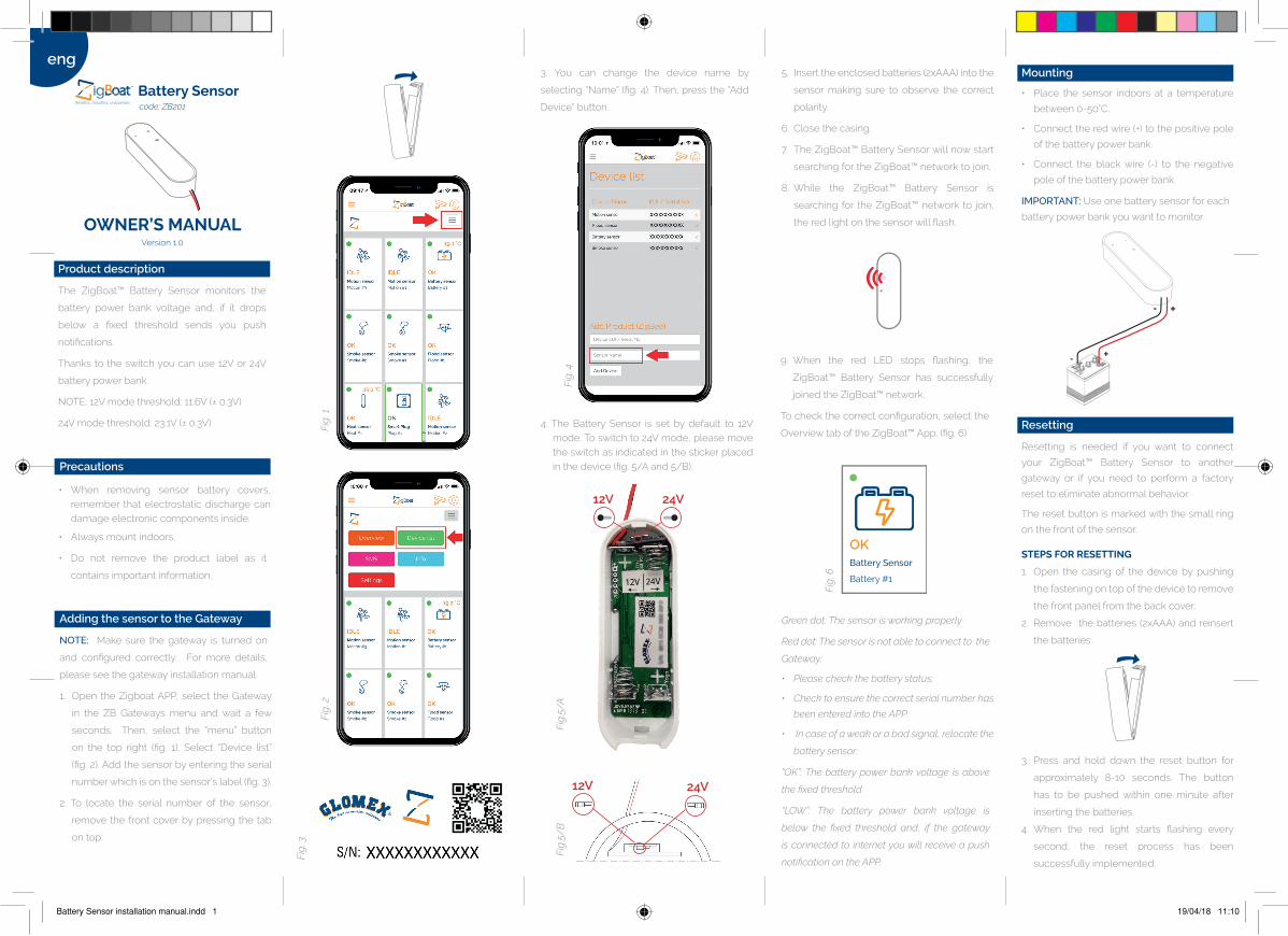
5. Inserttheenclosedbatteries(2xAAA)intothe
sensor making sure to observe the correct
polarity.
6. Closethecasing.
7. TheZigBoat™BatterySensorwillnowstart
searchingfortheZigBoat™networktojoin.
8. While the ZigBoat™ Battery Sensor is
searching for the ZigBoat™ network to join,
theredlightonthesensorwillflash.
4. The Battery Sensor is set by default to 12Vmode.Toswitchto24Vmode,pleasemovetheswitchasindicatedinthestickerplacedinthedevice(fig.5/Aand5/B).
3. You can change the device name by
selecting“Name”(fig.4).Then,pressthe“Add
Device”button.
Battery Sensorcode: ZB201
• When removing sensor battery covers,remember that electrostatic discharge candamageelectroniccomponentsinside.
• Alwaysmountindoors.
• Do not remove the product label as it
containsimportantinformation.
Product description
The ZigBoat™ Battery Sensor monitors the
battery power bank voltage and, if it drops
below a fixed threshold sends you push
notifications.
Thankstotheswitchyoucanuse12Vor24V
batterypowerbank.
NOTE:12Vmodethreshold:11.6V(±0.3V)
24Vmodethreshold:23.1V(±0.3V)
Precautions
Adding the sensor to the Gateway
NOTE: Make sure the gateway is turned on
and configured correctly. For more details,
pleaseseethegatewayinstallationmanual.
1. Open the ZigboatAPP, select the Gateway
in the ZB Gateways menu and wait a few
seconds. Then, select the “menu” button
on the top right (fig. 1). Select “Device list”
(fig.2).Addthesensorbyenteringtheserial
numberwhichisonthesensor’slabel(fig.3).
2. To locate the serial number of the sensor,
removethefrontcoverbypressingthetab
on top.
OKBattery Sensor
Battery #1
12V 24V
12V 24V
Fig
. 4
Fig
. 6
+
+
-
-
Battery Sensor installation manual.indd 1 19/04/18 11:10
Glomex assumes no responsibility for any
errors, which may appear in this manual.
Furthermore,Glomexreservestherighttoalter
the hardware, software, and/or specifications
GlomexguaranteestheBatterySensor(ZB201)
againstmanufacturingdefectsforaperiodof2
yearsfromdateofpurchase.Warrantycanbe
intheformofrepairorreplacementoftheunit
ifmanufacturingdefectshavebeenfoundand
areconfirmedbyGlomexoroneofitsaffiliates.
Inordertovalidatewarranty,eithertheoriginal
salesreceiptoracopymustbeprovidedatthe
time warranty is requested. Before returning
any items for warranty, please contact the
Glomex Customer Service department to
receive a RMA which should be completed
andsentwiththeunittothefollowingaddress:
GLOMEXS.r.l.
ViaFaentina165/G
48124Ravenna(Italy)
completewith all the accessories supplied at
the time of purchase for shipment. The serial
number must neither be erased nor made
illegible,otherwisethewarrantywillbevoided.
Consultailmanualeutenteinitalianosu:
Consultez le manuel d’utilisation en français
sur:
SiehedasdeutscheBenutzerhandbuchauf:
Consulteelmanualdeusuarioenespañolen:
All rights reserved.
Warranty
DistributedbyGlomexSrlviaFaentina165/G48124RavennaItaly
Other certifications
• ZigBee®certified.
IN ACCORDANCE WITH THE DIRECTIVES
• RadioEquipmentDirective2014/53/EU
• EMCDirective2014/30/EU
• RoHSDirective2011/65/EU
CE certification
The CE mark affixed to this product confirms
its compliance with the European Directives
which apply to the product and, in particular,
itscompliancewiththeharmonizedstandards
andspecifications.
Other information
Dispose the product and battery properly at
the end of life. This is electronic waste which
shouldberecycled.
Disposal
The use of ZigBoat™ Battery sensor is under
theresponsabilityoftheboatowner.
Battery replacement
CAUTION: RISK OF EXPLOSION IF BATTERIES
ARE REPLACED BY AN INCORRECT
TYPE. DISPOSE OF THE BATTERIES IN
ACCORDANCE WITH INSTRUCTIONS.
CAUTION: When removing cover for battery
change - Electrostatic Discharge (ESD) can
harmelectroniccomponentsinside
1. Open the casing of the device by pushing
the tab at the top of the device to remove
thefrontpanelfromthebackcover.
2. Replace the batteries respecting the
polarities. The ZigBoat™ Battery Sensor
uses(2xAAA)batteries.
3. Closethecasing.
4. TesttheZigBoat™BatterySensor.
Fault finding
• If the ZigBoat™ Battery Sensor does not
work,theprobablecauseisafaultybattery.
Replace the batteries (2xAAA) if they are
wornout.
• IfthesearchfortheZigBoat™Gatewayhas
timed out, a short press on the buttonwill
restartit.
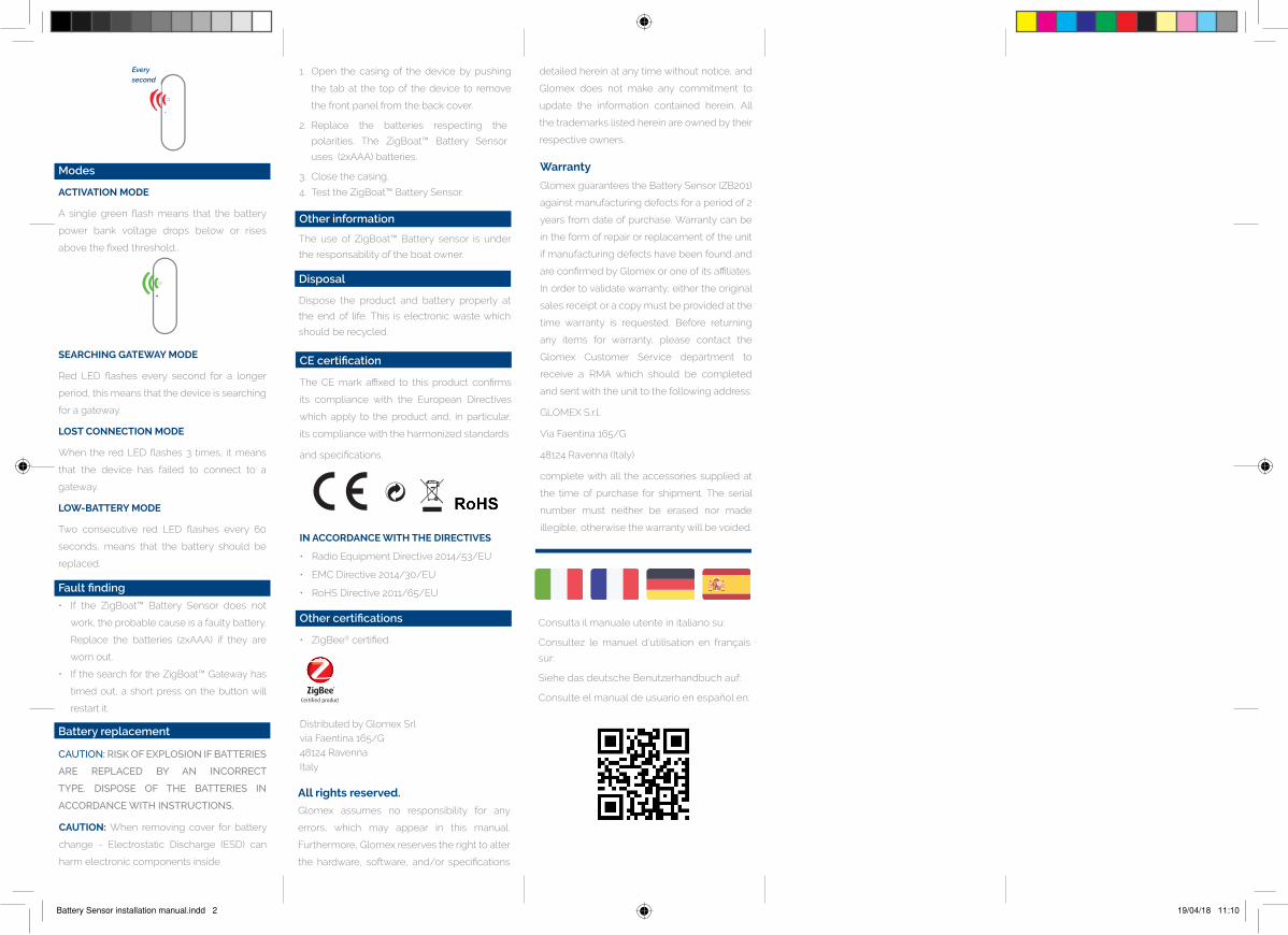
Modes
ACTIVATION MODE
A single green flash means that the battery
power bank voltage drops below or rises
abovethefixedthreshold..
SEARCHING GATEWAY MODE
Red LED flashes every second for a longer
period,thismeansthatthedeviceissearching
foragateway.
LOST CONNECTION MODE
When the red LED flashes 3 times, it means
that the device has failed to connect to a
gateway.
LOW-BATTERY MODE
Two consecutive red LED flashes every 60
seconds, means that the battery should be
replaced.
detailedhereinatanytimewithoutnotice,and
Glomex does not make any commitment to
update the information contained herein. All
thetrademarkslistedhereinareownedbytheir
respectiveowners.
Everysecond
Battery Sensor installation manual.indd 2 19/04/18 11:10