OWNER’S MANUAL / Vagabond Lithium Extremes196259524.onlinehome.us/manuals/vlx.pdf · 2 QUICK...
28
2725 Bransford Avenue // Nashville, Tennessee // 37204 Toll Free 1-800-443-5542 // Local Line (615) 383-3982 web www.paulcbuff.com // email [email protected] OWNER’S MANUAL / Vagabond ™ Lithium Extreme The Vagabond™ Lithium Extreme Portable Power System (VLX™) is a product by Paul C. Buff, Inc.™, designed and assembled in the USA, and sold Factory Direct from our offices in Nashville, TN. The VLX™ is the fourth generation of our popular Vagabond™ series, providing a reliable, current-limited, pure sine wave power source, optimized for field powering of studio flash units. Available in Navajo Turquoise / Purple Haze or Cool Grey (grey shown above). v.07/2014
Transcript of OWNER’S MANUAL / Vagabond Lithium Extremes196259524.onlinehome.us/manuals/vlx.pdf · 2 QUICK...

2725 Bransford Avenue // Nashville, Tennessee // 37204Toll Free 1-800-443-5542 // Local Line (615) 383-3982web www.paulcbuff.com // email [email protected]
OWNER’S MANUAL / Vagabond™ Lithium Extreme
The Vagabond™ Lithium Extreme Portable Power System (VLX™) is a product by Paul C. Buff, Inc.™, designed and assembled in the USA, and sold Factory Direct from our offices in Nashville, TN. The VLX™ is the fourth generation of our popular Vagabond™ series, providing a reliable, current-limited, pure sine wave power source, optimized for field powering of studio flash units.
Available in Navajo Turquoise / Purple Haze or Cool Grey (grey shown above).
v.07/2014

2 QUICK START / Charging Your Battery
We recommend charging the battery as soon as the systemis unboxed. Charge the battery using only the providedVLXCHG Vagabond™ Lithium Extreme Battery Charger.
Connect the battery charger’s power cord to the battery charger.Plug the cord’s male “figure eight” connector into the powercord receptacle on the battery charger.
!
to AC power source
1
1
2

3
Connect the battery charger’s power cord to AC power. Connect thetwo-pronged metal plug to a suitable AC power source. Whenconnected to power, the LED located on the top of the batterycharger will shine GREEN to indicate the connection.
Connect the battery charger to the battery. Connect the battery charger’s hardwired charging cable to the charging port locat-ed on the battery (labeled CHARGER IN). When connected, the LED on the charger will shine RED while the battery is charging, then shine GREEN to indicate that the battery is fully charged. Once complete, disconnect the charger from both the battery and the AC power source.
3
2
3

4 QUICK START / Connecting Flash Units
How many flash units can I connect?The VLX™ system can be used to provide power for multiple flash units with a combined total wattsecond rating of up to 3,200 Ws (i.e. one E640 Einstein™ flash unit at full power is rated at 640 Ws; if your setup included three E640 units, that would be a total of 1,920 Ws; up to 3,200 Ws may be connected). The recycle time between flashes and the total number of flashes available per battery charge will vary based on the power load con-nected (please see pg. 9 for specifications and additional details).
Connect your flash unit(s) to the VLX™ system. Plug one or two flash units into the AC power outlets located on the front control panel of the inverter. You can connect multiple units by using a multi-outlet extension cord or power bar, ensuring that you always use ground-ed outlets and extension cords.
1
standard flash unitAC power cord
(grounded cord)120 VAC, 60 Hzpower outlet----->
!
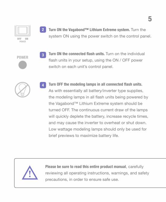
5Turn ON the Vagabond™ Lithium Extreme system. Turn thesystem ON using the power switch on the control panel.
Turn ON the connected flash units. Turn on the individualflash units in your setup, using the ON / OFF power switch on each unit’s control panel.
Turn OFF the modeling lamps in all connected flash units.As with essentially all battery/inverter type supplies,the modeling lamps in all flash units being powered bythe Vagabond™ Lithium Extreme system should be turned OFF. The continuous current draw of the lampswill quickly deplete the battery, increase recycle times,and may cause the inverter to overheat or shut down.Low wattage modeling lamps should only be used for brief previews to maximize battery life.
Please be sure to read this entire product manual, carefullyreviewing all operating instructions, warnings, and safety precautions, in order to ensure safe use.
2
3
4

6 SAFETY / Warnings and Precautions
As with all devices that use lithium batteries, misuse presents a potential risk of fire or other dangerous conditions. Read all warnings before use.
Do NOT operate, charge, or store the system in extreme hot or cold conditions.
Do NOT operate, charge, or store the system in or around water or any otherliquid as this increases the potential risk of fire. The system should only be used in dry conditions where it is protected from natural elements. Do NOT operate, charge, or store the system in or around flammable materials.
Do NOT use any Paul C. Buff™ equipment in restricted areas.
Do NOT disassemble any components. There are no user-serviceable partsand you should never open, disassemble, or attempt to repair or make modifications to any components as this can create a shock hazard.
Do NOT shake the system, expose it to severe vibration, or allow any component tobe dropped or crushed. Discontinue use if the system becomes damaged.
Do NOT insert any tools or foreign objects into any outlets or ventilation holes.Do not allow loose metal objects to come into contact with the battery.
Do NOT block ventilation holes or in any way cover the system or charger while inuse or while charging. Do not operate or charge the system from the insideof a bag as the system and charger get warm during operation and mustnot be enclosed or covered while in use. Do not operate or charge the battery if it gets uncomfortably hot to the touch.
Turn OFF the modeling lamp(s) in all connected flash units. Continuous modeling lamps operation quickly depletes the battery and can overheat the inverter or cause erratic recycling.
Do NOT use ungrounded power cords. Always use three-pronged, grounded power cords and power strips when connecting equipment to the system. Do not use any adapters that defeat the third prong.

!If any components become damaged, wet, or unable to performnormally, discontinue use immediately. Turn the system off,unplug all cords, and contact our Customer Service Team.Failure to observe any of these warnings may present ahazardous condition and potentially void the warranty.
Use only the approved, supplied battery charger to charge the system’s battery. The battery should be recharged within 48 hours of complete discharge to avoid the possibility of damage. Apply a partial charge to ~40% for stor-age, then the battery can be fully charged prior to use.
When storing the battery for long periods of time, the battery should be mainte-nance charged every three months to maximize life. Do not store a fully dis-charged battery as this may result in degradation of internal components.
After storage, confirm that the battery can provide power before using it or charging it. Connect the battery to the inverter and turn the inverter ON. If none of the battery status LED lights shine to indicate a charge status, do NOT use the system or charge the battery. The battery may have been damaged by improper storage and should NOT be used. See page 24 for more details on battery care and storage.
Do NOT leave the system unattended while in use or while charging the battery.Do not allow children around this equipment. Only connect 120V devices. Do not use outlet adapters to connect devices of incompatible voltage to the VLX™ system as this can damage the equip-ment and/or the VLX™ system. Do not put a continuous load higher than 400 Watts on the inverter as this may cause the unit to overheat and shut down. Use care when traveling with or transporting the system. Use appropriate pack-aging to protect the system and components from being damaged.

8 OVERVIEW / Components and Specs
The Vagabond™ Lithium Extreme (VLX™) Portable Power System provides a current-limited, pure sine wave power source, optimized for field powering of 120V studio flash units that are normally AC-powered. The system ar-rives with the VLXBAT battery, the VLXINV inverter (with light stand mount attached), and the VLXCHG battery charger.
the VLXBAT Vagabond™ Lithium Extreme BatteryThe 25.6V, high capacity lithium iron phosphate (LiFePO4) battery offers long life and increased performance. The design includes a convenient front panel connection for charging using the supplied rapid battery charger.
Battery Ratings 25.6V, 6.2AH, 158.7 Wh, 20A max. cont. current
Voltage Full Charge: 29VDC, Cutoff: 20VDC 20A DC nominal output
Battery Lifespan 1000 - 1500 charge/discharge cycles
System Weight 6 pounds (excluding charger)
Component Weights 2.2-pound inverter / 3.8-pound battery
System Dimensions 6.5” h x 5” w 7.8” d (with stand clamp)
Inverter Dimensions 2.4” h x 5” w 7.8” d (without clamp)
Battery Dimensions 2.4” h x 5” w 7.5” d

9
the VLXINV Vagabond™ Lithium Extreme InverterThe inverter takes the power from the battery and converts it into a usable, 120 VAC pure sine wave power source. The inverter control panel includes two grounded power outlets, a 2A USB outlet, a multi-level accurate battery charge indi-cator, and a sliding battery lock / release tab.
Power Outlets 120 VAC, 60 Hz
Max. AC Output Current 3.3A RMS at 120 VAC
Max. Continuous Load 400 Watts
the VLXCHG Universal Rapid Battery ChargerConnecting directly to the battery, the charger plugs into an AC power source (100 to 240 VAC) to recharge the battery in just 3 to 4 hours.
Charger Input 100-240 VAC, 50/60Hz, 50VA
Charger Output 29VDC, 2A
the Light Stand Mount The VLX™ includes a robust mounting mech-anism (attached to the inverter), allowing the system to be securely mounted on light standswith center poles up to 1.5” in diameter.
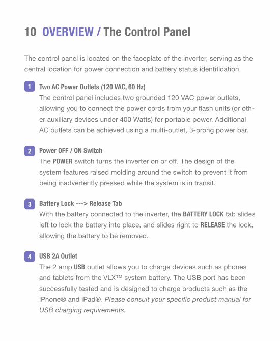
10 OVERVIEW / The Control Panel
The control panel is located on the faceplate of the inverter, serving as the central location for power connection and battery status identification.
Two AC Power Outlets (120 VAC, 60 Hz) The control panel includes two grounded 120 VAC power outlets,allowing you to connect the power cords from your flash units (or oth-er auxiliary devices under 400 Watts) for portable power. Additional AC outlets can be achieved using a multi-outlet, 3-prong power bar.
Power OFF / ON SwitchThe POWER switch turns the inverter on or off. The design of the system features raised molding around the switch to prevent it from being inadvertently pressed while the system is in transit.
Battery Lock ---> Release TabWith the battery connected to the inverter, the BATTERY LOCK tab slides left to lock the battery into place, and slides right to RELEASE the lock, allowing the battery to be removed.
USB 2A OutletThe 2 amp USB outlet allows you to charge devices such as phones and tablets from the VLX™ system battery. The USB port has been successfully tested and is designed to charge products such as the iPhone® and iPad®. Please consult your specific product manual for USB charging requirements.
1
2
3
4

Battery Status Indicator LED LightsA multi-level battery charge indicator constantly monitors the con-nected battery. A single LED shines to indicate the BATTERY STATUS:
• RED = 1% to 10% charged = battery must be recharged before use• YELLOW = 11% to 40% charged = battery is low, recharge soon• GREEN = 41% to 100% charged = battery is charged enough for use
30A FuseA single blade-type 30A FUSE is located on the control panel so that you can monitor the fuse status and replace it if necessary. It is ex-tremely unlikely that a fuse will blow unless a fault should occur in the inverter. For additional details on a blown fuse, see page 22.
Ground ConnectionThe GROUND outlet allows the system to be connected to an actual Earth ground. As the inverter’s AC output is completely isolated from any other reference, it is intrinsically safe and this connection will very rarely be needed. For additional details on grounding, see page 23.
5
6
7

12 OPERATION / Connecting The Battery
The VLX™ inverter and battery connect quickly, secured in place or re-leased using the sliding battery lock tab located on the control panel.
Locate the battery lock tab on the front control panel of the inverter (labeled BATTERY LOCK ---> RELEASE). When the battery is not attached to the inverter, the tab rests in the right RELEASE position.< sliding the tab to the LEFT locks the battery in place> sliding the tab to the RIGHT releases the battery lock
Ensure that the POWER switch on the inverter is in the OFF position with the left side of the switch pressed down.
Locate the red and black Anderson connectors on the battery. The battery electrically connects to the inverter with these Anderson connectors. Sliding the battery into place and latching it to the inverter allows the set of Anderson connectors to interlock.
Align the battery and the inverter so that the molded latches face each other. Slide the battery down, allowing the two grooves on the bottom of the battery to fit over the corresponding bottom latches on the inverter.
Fit together the battery and inverter, allowing the Anderson connectors on the battery to be matched to their corresponding sockets on the in-verter. The three L-shaped top latches on the battery fit into the three corresponding grooves on the inverter.
1
2
3
4
5

With the battery in place, slide the battery lock tab on the inverter’s control panel to the left, securing the connection.
To disconnect the battery from the inverter, ensure that the POWER switch is in the OFF position and slide the tab to the right to release the battery lock. Note: If the battery release tab does not side freely when you are trying to remove the battery, squeeze the battery and inverter together while moving the tab.
6
SIDE VIEWof thePURPLE andTURQUOISEVLX™
SIDE VIEWof theCOOL GREYMODEL
BATTERY
INVERTER
the battery electrically connects to the inverter with a pair of red and black Anderson connectors
sliding the BATTERY LOCK tab to the left secures the attachment
BATTERY
INVERTER

1
2 3
14 OPERATION / Charging The Battery
Charge the battery using the VLXCHG charger supplied with the system.
The battery can remain connected to the inverter during charging or be charged separately (disconnected from the inverter). When connected, turning theinverter OFF will maximize charging speed. Keeping the inverter ON will allow you to monitor the charging progress using the battery status LED indicators on the control panel. Note: The third LED on the control panel will shine GREEN once the battery reaches 41% charge, but the LED onthe charger itself will not shine GREEN until the battery is 100% charged.
The system can be used while the battery is charging, allowing continuousoperation in most cases. Since the charger replenishes the battery contin-ually in this type of use, the battery life is dramatically extended beyond the specified life. With heavy power loads and rapid shooting, however, it is possible for charging to fall behind discharging.
The battery charger can be used globally on 100 - 240 VAC power lines. To usethe charger internationally, you will need to purchase a plug adapterwith the correct outlet configuration for your location.
•
•
•
•

Connect the battery charger’s power cord to the charger. Plug the cord’s female “figure eight” connector into the power cord receptacle.
Connect the battery charger’s power cord to AC power. Plug the power cord into a suitable AC power source. When connected to power, the LED on the battery charger will shine GREEN to indicate the connection.
Connect the battery charger to the battery. Connect the charging cable to the battery charging port (CHARGER IN). The LED on the charger will shine to indicate the status of the charging process whenever the charger is connected to the battery (and connected to AC power):
Solid or Blinking GREEN = the battery is fully charged Solid RED = the battery is charging Blinking RED = error message = discontinue use
It is normal for the charger to get hot while in use. Ensure that the char-ger is not covered or placed on a surface that conducts heat. When charging is complete, disconnect the charger from the battery and the AC power source and allow it to cool before handling.
A fully depleted battery will charge to 100% in 3 to 4 hours. There is no risk of overcharging, but the charger should be disconnected from the battery within two hours once charging is complete.
1
2
3
If any aspect of the charging process is abnormal, discontinue use immediately. Disconnect the charger, turn the system OFF, and contact our Customer Service team for support.!
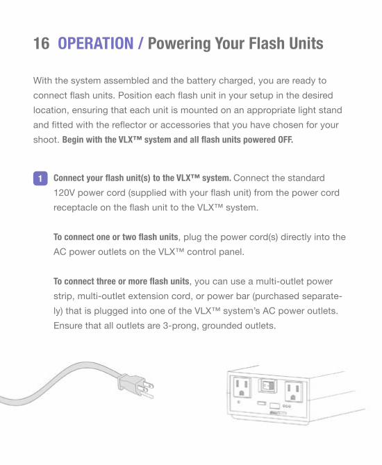
16 OPERATION / Powering Your Flash Units
Connect your flash unit(s) to the VLX™ system. Connect the standard120V power cord (supplied with your flash unit) from the power cord receptacle on the flash unit to the VLX™ system.
To connect one or two flash units, plug the power cord(s) directly into the AC power outlets on the VLX™ control panel.
To connect three or more flash units, you can use a multi-outlet power strip, multi-outlet extension cord, or power bar (purchased separate-ly) that is plugged into one of the VLX™ system’s AC power outlets. Ensure that all outlets are 3-prong, grounded outlets.
1
With the system assembled and the battery charged, you are ready to connect flash units. Position each flash unit in your setup in the desired location, ensuring that each unit is mounted on an appropriate light stand and fitted with the reflector or accessories that you have chosen for your shoot. Begin with the VLX™ system and all flash units powered OFF.

17Turn ON the VLX™ system using the power switch on the control panel.
Turn ON the connected flash units. Turn on each flash unit in your setup normally, using the ON / OFF power switch on each individual unit.
Turn OFF the modeling lamps in all connected flash units. As with essen-tially all battery/inverter type supplies, the modeling lamps in all flash units being powered by the VLX™ system should be turned OFF. The continuous current draw of the lamps would quickly deplete the bat-tery, increase recycle times, and could cause the inverter to overheat. Modeling lamps should be used for brief previews only. Low wattage modeling lamps are available for Buff™ flash units, for use when mod-eling light is required.
3
2
OPERATION / Using The CyberSync™ SystemThe Paul C. Buff™ Cyber Commander™ remote control and CyberSync™ receivers may be set up normally for use with flash units being powered by the VLX™ system. The VLX™ system will reliably power the flash units and any AC-powered CyberSync™ receivers using pass-through power cords.
When using the Cyber Commander™ remote control, be sure to turn OFF the modeling lamp on the control panel of each connected flash unit. For each corresponding light channel in the Cyber Commander™ remote con-trol, ensure that the MODEL function is set to OFF in the LIGHT SETTINGS menu as well to prevent erratic behavior.
4

18 OPERATION / Powering Flash Units By Other Manufacturers
The VLX™ system is designed to provide portable power for Paul C. Buff™ flash units, however, the system can be used to power almost all other brands of photographic flash units as well. While we are not able to test the VLX™ system with all of the various brands and models of flashes available, the system should work with nearly all standard photographic flash units (both analog and digital, including multiple multi-voltage units). To find out about a specific flash unit, contact our Customer Service Team and we’ll be hap-py to provide you with any details that we have for the unit.
While we feel confident that the VLX™ system can be used to power vari-ous brands of flash units, we cannot make any claim for suitability with any in-dividual products made by other manufacturers, nor can we accept any liability for any damage that might be caused to such equipment. We do, however, warranty the VLX™ system itself as well as any Paul C. Buff™ equipment it powers.
OPERATION / Powering Auxiliary EquipmentThe VLX™ system may be used to power non-flash continuous loads forsmall electrical appliances (such as fans, radios, laptops, tablets, etc.) aslong as the maximum continuous power drawn in such applications is less than 400 Watts.

19
While it is generally not advisable to use the VLX™ system to power flash units and continuous power loads at the same time, if a continuous load is being powered in conjunction with flash units, the maximum power draw should be reduced. When a continuous load is powered in conjunction with one or more flash units, the battery charge will be depleted much faster, resulting in less flashes available per battery charge and slower recycle times.
Note: When the VLX™ system is used to power and recycle flash units, the output voltage will not remain constant at 120 VAC. During recycle, output voltage will drop to as low as 60 VAC, depending on the number and type of flash units connected. This is intrinsic with all current-limited, battery-to-AC power systems. Equipment that requires continuous 120 VAC power should NOT be connected to the system for simultaneous powering alongside flash units. To the best of our knowledge, the momentary low voltage will not affect laptops connected by their battery chargers. AC-powered computers, however, may crash under this brown-out condition and draw more watts than what can be acceptably drawn from the system. If you plan to power auxiliary equipment, you should consult the owner’s manual for your spe-cific equipment to determine the power consumption.
When powering auxiliary equipment, the maximumcontinuous power draw permitted is 400 Watts.Consult the manual for each device to determineits power draw. Do NOT use the VLX™ system to powerdevices that draw more than 400 Watts.
!

20 OPERATION / Typical Performance
Based on the total number of wattseconds being powered by the VLX™ system (the combined total of all connected flash units), these specifications indicate the typical number of full power flashes and the approximate recycle time expected from a fully charged battery.
The number of expected flashes depends on the total number of flash units connected, the power model of each, and the power output setting of each. The more true wattseconds connected, the longer the recycle time. The practical limits are based more on the total wattseconds being cycled than on the number of flash units. The largest prac-tical load for the system is dependent on the flash unit power settings. Heavy loads can be expected to reduce the efficiency and will likely reduce the recycle rate. The number of flashes available per charge decreases if you begin with a battery that is not fully charged. The guideline information provided on the typical number of flashes is based on use with a fully charged battery.
The number of flashes available per charge will drastically decrease and the recycle times will drastically increase if the modeling lamps are turned on in any connected units, or when the VLX™ system is used to simultaneously power flash units along with any other continuous load auxiliary equipment. Please note that the estimates provided are based on typical performance of a battery that is fully charged and in good condition, with modeling lamps in all units turned OFF.
Note: All flash units, and the VLX™ itself, draw some current when powered on, but idle. This idle current varies by item, and will eventually deplete the battery charge, even when lights are not being flashed. The greater the number of units connected to a single VLX™ system, the shorter the battery standby life. To maximize battery life during a session, the VLX™ should be switched OFF when not in use.

21Total Wattseconds Expected # of Flashes Recycle Time (between each flash)
160 Wattseconds 2000 flashes 0.5 seconds 160 Wattseconds (examples) = 1 AlienBees™ B400 Flash Unit at Full Power 1 AlienBees™ B800 Flash Unit at Half Power (-1f) 1 Einstein™ E640 Flash Unit at Quarter Power (-2f) 2 AlienBees™ B400 Flash Units, each at Half Power (-1f)
320 Wattseconds 1000 flashes 1 second 320 Wattseconds (examples) = 1 AlienBees™ B800 Flash Unit at Full Power 1 Einstein™ E640 Flash Unit at Half Power (-1f) 2 AlienBees™ B400 Flash Units, each at Full Power 2 Einstein™ E640 Flash Units, each at Quarter Power (-2f)
640 Wattseconds 500 flashes 2 seconds 640 Wattseconds (examples) = 1 AlienBees™ B1600 or 1 Einstein™ E640 Flash Unit at Full Power 2 Einstein™ E640 Flash Units, each at Half Power (-1f) 4 AlienBees™ B400 Flash Units at Full Power
1280 Wattseconds 250 flashes 4 seconds 1280 Wattseconds (examples) = 2 AlienBees™ B1600 or 2 Einstein™ E640 Flash Units at Full Power 4 AlienBees™ B800 or 8 AlienBees™ B400 Flash Units at Full Power
2560 Wattseconds 125 flashes 8 seconds 2560 Wattseconds (examples) = 4 Einstein™ E640 or 8 AlienBees™ B800 Flash Units at Full Power
3200 Wattseconds 90 flashes 10 seconds 3200 Wattseconds (example) = 5 Einstein™ E640 Flash Units at Full Power

22 OPERATION / The Light Stand Mount
The VLX™ system arrives with a light stand mounting mechanism that allows it to be verti-cally mounted on a light stand for a convenient connection. The mechanism includes a clamp, a screw, and a tightening wheel.
The center pole on all Paul C. Buff™ light stands and most other standard light stands (with up to 1.5” diameter poles) fits between the two sides of the clamp - one side is permanently affixed to the inverter housing, the other tightens / loosens with the tightening wheel. Spinning the tightening wheel clockwise tightens the screw to secure the position. Maximum stability can be gained by mounting the VLX™ near the bottom of the stand, where it will additionally serve as a stand weight.
OPERATION / The FuseThe VLX™ system uses a single blade-type, 30A fuse, located on the front control panel (automotive type fuse, available at any auto supply store). It is extremely unlikely that the fuse will blow unless a fault should occur in the inverter. Should the fuse blow, discontinue use, disconnect all cords, and contact our Customer Service Team to determine if the fuse should be replaced or if service is required for your system.
twist clockwiseto tighten

OPERATION / GroundingThe AC outputs on the inverter are completely isolated from any other reference, making the system intrinsically safe without connecting it to an actual Earth ground. A GROUND connection is provided, however, should you wish to connect the system to an actual Earth ground if the flash units being powered are flashing erratically due to external electrical interfer-ence. This connection will very rarely be needed. Contact our Customer Service Team if you need assistance with grounding.
OPERATION / International UseThe VLX™ system is a great solution for powering your standard 120V flash units when traveling internationally. The battery can be recharged globally (100 to 240 VAC) with the universal battery charger, requiring only a simple outlet adapter for the battery charging cable, purchased locally to fit the wall outlet configuration of your location.
For studio use in countries operating on voltages other than 120V, the VLX™ system may be operated while the charger is connected. The high capac-ity battery, high output inverter, and rapid charger will provide seamless shooting at relatively fast recycle rates. Since the charger replenishes the battery continually, the battery life is dramatically extended beyond the specified life. With heavy power loads, however, charging can fall behind discharging. For uninterrupted operation, ensure that the modeling lamps are turned OFF in all connected flash units and do not attempt to power continuous load auxiliary equipment simultaneously.
23

24 MAINTENANCE / Battery Care and Storage
The lifespan of your VLXBAT battery will vary based on several factors including frequency of use; power load while in use; charge level, envi-ronmental conditions, and ambient temperature (both when the unit is in use and in storage); and overall battery age. To maximize the lifespan of your battery, we recommend the following:
Always store the system in safe, dry, moderate conditions, away from flam-mable materials, where the equipment is protected from water and dirt.
Do NOT store your battery in a hot environment (above 86ºF) such as an attic or a car on a warm day. Leaving a battery in a hot environment, especially when exposed to the sun, speeds up capacity loss. A fully charged battery stored at elevated temperatures is even worse.
Do NOT store your battery in a cold environment (below 32ºF). After storage, note that moving the system from one environment to another can cause condensation to occur due to temperature changes. Do not op-erate or charge the system until all condensation has fully evaporated.
After the battery has been depleted, apply a partial charge before storage. Charge the depleted battery for approximately one hour, applying a partial charge to ~40% capacity (using the battery status LEDs on the inverter’s control panel as a guide, when the YELLOW LED turns off and the GREEN LED first turns on, the battery is charged to ~40% capacity).Turn the system OFF, disconnect the battery charger, and disconnect the battery for storage.
•
•
•
•

25
When removing your battery from storage, confirm that the battery can provide power before using or charging it. Connect the battery to the in-verter and turn the inverter ON. If none of the battery status LED lights shine to indicate a charge status, do not use the system or charge the battery. The battery may have been damaged by improper storage and should NOT be used.
A battery that has been properly taken care of should deliver approximately 1000 to 1500 charge / discharge cycles. When the battery capacity drops to 50% (when the number of full power flashes, per wattsecond rating, per full bat-tery charge is halved), we recommend replacing it. If the battery is used and stored properly, it should have a shelf life over 10 years.
It is best to recharge the battery as soon as possible after use. The battery should be recharged within 48 hours of complete discharge to avoid the possibility of damage. Apply a partial charge to ~40% for storage,then the battery can be fully charged prior to use.
When storing the battery for long periods of time, the battery should be mainte-nance charged every three months to maximize life. For long-term storage, do not allow the battery to be fully discharged then stored as this may result in degradation of the internal components.
•
•

26 TRAVEL / Airline Travel Information
The battery used in the VLX™ system is a lithium iron phosphate (LiFePO4) battery. Lithium batteries of this type are regulated for air travel by both the U.S. Dept. of Transportation (DOT) and the International Air Transport Association (IATA).
Based on the specifications of the battery, the current DOT and IATA regu-lations indicate that the system is approved for travel by air as carry on baggage, however, you must check with your individual airline carrier in order to find out the updated regulations for your specific flight based on the specif-ic items with which you wish to travel. To determine eligibility for travel, you may be asked for certain specifications of the battery which are both printed on the battery and provided in this manual. Additionally, you should download and print the travel documentation for the system that is available on our website (http://www.paulcbuff.com/manuals/vlxbat_travel.pdf).
You must check with your individual airline carrier in order to findout the updated, applicable regulations for your specific flight.
VLXBAT Battery Specs For Reference:• lithium iron phosphate (LiFePO4) battery• 25.6 Volts (V), 6.2 Amp-hours (Ah), 158.7 Watt-hours (Wh)
!

You must check with your individual airline carrier in order to findout the updated, applicable regulations for your specific flight.
VLXBAT Battery Specs For Reference:• lithium iron phosphate (LiFePO4) battery• 25.6 Volts (V), 6.2 Amp-hours (Ah), 158.7 Watt-hours (Wh)
27ACCESSORIES / Optional AdditionsVLXBAG Carrying Bag: Custom designed for the VLX™ system, this padded nylon carrying bag offers a convenient option for around-town travel. Sold separately - learn more at www.paulcbuff.com/vlxbag.php.
VM-UPC3-120V 3-Foot Power Cord: We offer a short power cord (120V) for use with Einstein™, AlienBees™, and White Lightning™ flash units to minimize cord tangle between the flash unit and the VLX™ system. Sold separately - learn more at www.paulcbuff.com/powercords.php.
DISPOSAL / Recycling The BatteryTo discard an exhausted battery in a safe and environmentally friendly way, take the battery to a rechargeable battery recycling center. Visit the Call2Recycle website (www.call2recycle.org) to find recycling locations in your area. Please note that regulations pertaining to battery recycling and disposal vary by state within the U.S. and internationally. Check the laws and regulations for your location for acceptable disposal practices.
WARRANTY / Service and SupportThe VLX™ system arrives with our 60-Day Absolute Satisfaction Guarantee and a 1-Year Factory Warranty. Paul C. Buff, Inc.™ guarantees to the original pur-chaser an individual product factory warranty against manufacturer defects in materials and workmanship, beginning with the date that the product is originally shipped to the customer. Please see our website for complete de-tails on our guarantee and factory warranty.

2725 Bransford Avenue // Nashville, Tennessee // 37204Toll Free 1-800-443-5542 // Local Line (615) 383-3982web www.paulcbuff.com // email [email protected]