OWNER’S MANUAL - V E S T I L D O C S . C O M MANUAL.pdfINSTALLATION INSTRUCTIONS – EHLTG Review...
12
Contents: Warnings & Safety Instructions ........................1 Replacement Parts............................................1 Receiving Instructions .....................................1 Installation Instructions.................................... 2 Operation Instructions ..................................... 3 Routine Maintenance & Safety Checks ........... 4 1 VESTIL MANUFACTURING CORPORATION P.O. Box 507., Angola, IN 46703 USA Phone (260) 665-7586 • Fax (260) 665-1339 E-mail: [email protected] • www.vestil.com OWNER’S MANUAL GROUND LIFT SCISSOR TABLES SERIES EHLTG Exploded Structural Parts Drawing & BOM......... 5 Electrical & Hydraulic Diagrams & BOM .......6-8 Power Unit’s Operation .................................... 9 Troubleshooting ............................................. 10 Safety Label Identification .............................. 11 Warranty ......................................................... 12 RECEIVING INSTRUCTIONS Every unit is thoroughly tested and inspected prior to shipment. However, it is possible that the unit could incur damage during transit. Inspect the unit closely when it arrives. If you see evidence of damage or rough handling to either the packaging or to the product when it is being unloaded, immediately make a note of it on the Bill Of Lading! It is important that you remove the product’s packaging upon its arrival to ensure that there is no concealed dam- age or to enable a timely claim with the carrier for freight damage. Also verify that the product and its specifications are as ordered. EHLTG-SERIES GROUND LIFT SCISSOR TABLE Ergonomic Solutions WARNINGS & SAFETY INSTRUCTIONS Ensure that all employees understand and follow the following. • Read and understand the owner’s manual before using or servicing the lift. • The load must be removed and either the leg set lowered onto the maintenance props or the platform fully lowered to the floor before any work is performed on the hydraulic system. • Ensure that all safety and warning labels stay in place and are legible. • Do not use the lift if any damage or unusual noise is observed. • Always watch the load and around the lift’s sides carefully when the lift is in operation. • Do not perform any modifications to the lift without the manufacturer’s approval. Failure to receive authorization for changes to the equipment could void the warranty. • Maintenance and repairs are to be done only by personnel qualified to perform the required work. • Do not use brake fluid or jack oils in the hydraulic system. If oil is needed, use an anti-wear hydraulic oil with a viscosity grade of 150 SUS at 100°F, (ISO 32 cSt @ 40°C), or Dexron transmission fluid. WHEN ORDERING REPLACEMENT PARTS We take pride in using quality parts on the equipment we manufacture. We are not responsible for equipment problems resulting from the use of unapproved replacement parts. To order replacement or spare parts for this equipment, contact the factory. In any communication with the factory please be pre-pared to provide the machine’s serial number, which is indicated on the machine dataplate. Revised 11-13 04-126-121 A company dedicated to solving ergonomic and material handling problems since 1955.
Transcript of OWNER’S MANUAL - V E S T I L D O C S . C O M MANUAL.pdfINSTALLATION INSTRUCTIONS – EHLTG Review...
Contents:Warnings & Safety Instructions ........................1 Replacement Parts............................................1 Receiving Instructions .....................................1 Installation Instructions.................................... 2 Operation Instructions ..................................... 3 Routine Maintenance & Safety Checks ........... 4
1
VESTIL MANUFACTURING CORPORATIONP.O. Box 507., Angola, IN 46703 USA
Phone (260) 665-7586 • Fax (260) 665-1339 E-mail: [email protected] • www.vestil.com
OWNER’S MANUAL GROUND LIFT SCISSOR TABLES SERIES EHLTG
Exploded Structural Parts Drawing & BOM......... 5 Electrical & Hydraulic Diagrams & BOM .......6-8 Power Unit’s Operation .................................... 9 Troubleshooting ............................................. 10 Safety Label Identification .............................. 11 Warranty......................................................... 12
RECEIVING INSTRUCTIONSEvery unit is thoroughly tested and inspected prior
to shipment. However, it is possible that the unit could incur damage during transit.
Inspect the unit closely when it arrives. If you see evidence of damage or rough handling to either the packaging or to the product when it is being unloaded, immediately make a note of it on the Bill Of Lading!
It is important that you remove the product’s packaging upon its arrival to ensure that there is no concealed dam-age or to enable a timely claim with the carrier for freight damage.
Also verify that the product and its specifications are as ordered.
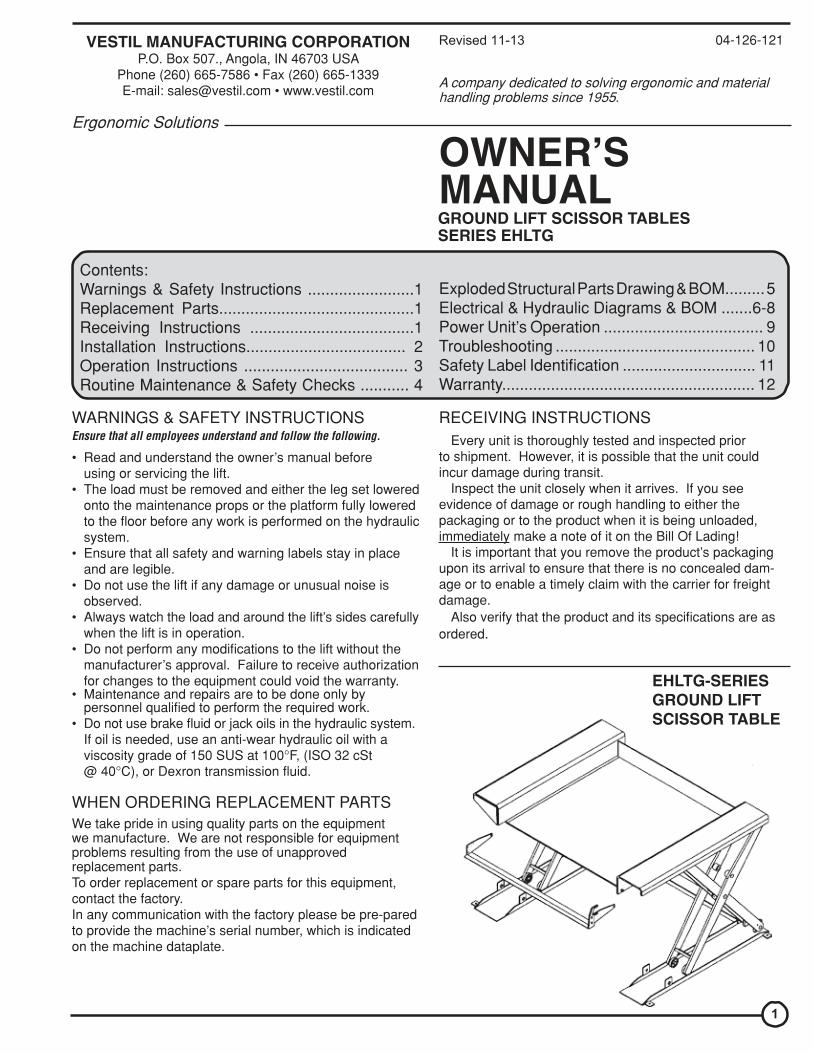
EHLTG-SERIES GROUND LIFT SCISSOR TABLE
Ergonomic Solutions
WARNINGS & SAFETY INSTRUCTIONSEnsure that all employees understand and follow the following.
• Read and understand the owner’s manual beforeusing or servicing the lift.
• The load must be removed and either the leg set loweredonto the maintenance props or the platform fully loweredto the floor before any work is performed on the hydraulicsystem.
• Ensure that all safety and warning labels stay in placeand are legible.
• Do not use the lift if any damage or unusual noise isobserved.
• Always watch the load and around the lift’s sides carefullywhen the lift is in operation.
• Do not perform any modifications to the lift without themanufacturer’s approval. Failure to receive authorizationfor changes to the equipment could void the warranty.
• Maintenance and repairs are to be done only bypersonnel qualified to perform the required work.
• Do not use brake fluid or jack oils in the hydraulic system.If oil is needed, use an anti-wear hydraulic oil with aviscosity grade of 150 SUS at 100°F, (ISO 32 cSt@ 40°C), or Dexron transmission fluid.
WHEN ORDERING REPLACEMENT PARTS We take pride in using quality parts on the equipment we manufacture. We are not responsible for equipment problems resulting from the use of unapproved replacement parts. To order replacement or spare parts for this equipment, contact the factory. In any communication with the factory please be pre-pared to provide the machine’s serial number, which is indicated on the machine dataplate.
Revised 11-13 04-126-121
A company dedicated to solving ergonomic and material handling problems since 1955.

INSTALLATION INSTRUCTIONS – EHLTG Review this entire page before installing the ground-clearance scissor lift.
Consult the factory in the event there are any questions or problems at the time of installation, or forinformation regarding optional features not covered by the owner’s manual.
The lift must be removed from the shipping wood and securely anchored to the floor before use! • Modifications or additions made without prior manufacturer’s authorization may void the lift’s warranty. The addition of
ancillary equipment to the lift may necessitate that its load capacity be reduced. • The installation must be made so that it complies with all the regulations applicable to the machine and its location. The
end-user must verify that the supplied equipment is installed so it will be suited to the environment in which it will be used.
• Installation must be performed by suitably trained personnel with access to the appropriate equipment. The electrical aspects of the installation should be performed by an electrician.
For a typical installation you will need the following: 1. A fork truck or hoisting means to unload the lift from the freight truck and set it into place. 2. A smooth, level, and adequately strong concrete surface on which to mount the lift. 3. Concrete anchors, a masonry drill, a masonry bit, hand tools, grout, and steel shims. Consult the building’s architect or
facility engineer to determine the best size and type of hardware with which to anchor the machine to the floor. 4. A power supply circuit and disconnect matching the motor voltage and current requirements. Refer to the machine’s
dataplate, to the labels on the control enclosure, and to the electrical section in this manual for more information. The end-user is responsible for supplying the branch circuit’s required overcurrent and short-circuit protection, which typically can be a 20A (maximum) inverse-time circuit breaker.
1. The lift must be lowered and fully supported. Move the lift into place with straps or forks placed underneath both the frame and the platform. Use care to avoid damage to the electrical or hydraulic components from the remotely-located power unit attached at the operator’s side of the lift.
2. Temporarily connect the power supply to the pigtail cord supplied with the power unit, and raise the platform so the lift’s safety maintenance props can be utilized. Lower the platform so the legset is supported on the maintenance props.
3. Anchor the frame to the floor through the 9/16” holes located at the corners of the frame. 4. Shim and/or grout under the full length of the frame sides. 5. Make permanent connection to the power supply, using an appropriate wiring method. 6. Operate the lift through several full up and down cycles. Verify that the upper travel limit switch (mounted in one side
of the leg set) and the toe guard switch (at one end of the toe guard bar, across the loading side of the platform) function properly.
7. Check the remote power unit’s hydraulic oil level. It should be filled to within 1” to 1½” of the reservoir’s fill hole. If oil is needed, use an anti-wear hydraulic oil with a viscosity grade of 150 SUS at 100°F (ISO 32 at 40°C) or a non-synthetic automatic transmission fluid.
8. Clean up any debris or spilled oil, and verify that all of the warning and safety labels are intact. • If the platform must be raised without first having the proper power supply connected, raise the platform at the end of
the lift to which the electrical cord and hydraulic hose attaches. Use a lifting hook on each side, attached near the deck hinges. With this method, the frame must be held down at the hinged end of the lift while the platform is raised.
2

OPERATION INSTRUCTIONS – EHLTG
• Consult ANSI MH29.1, Section 12 for the owner’s / user’s responsibilities regarding the operation, care, and maintenance of this machine.
• Ensure that all employees involved in the operation of this lift understand and follow these instructions! The standard model EHLTG is suitable for use indoors in most industrial locations and many commercial locations.
It is intended to be used to elevate stable, nonhazardous loads having a size or footprint no larger than the dimensions indicated in the model number.
Loading: The load rating, in pounds, is shown on the machine dataplate located on the hinged end of the platform. It indicates the net capacity of the scissor lift with a static load that is centered and evenly distributed on the platform.
When not fully lowered, the lift’s maximum single axle load rating is 60% of the full-load capacity for end loading. (The hydraulic hose and the bridge plates are at the lift’s “end.”) Do not exceed a rate of two feet per second when moving loads across the platform.
Note: The addition of any ancillary equipment to the machine by third parties must be taken into account when determining the maximum working load to be placed on the platform.
Warning: Do not exceed the lift’s load ratings. Injury to personnel and/or permanent damage to the lift could result from exceeding the listed capacity.
Operation: Inspect the perimeter pinch point guard’s operation daily.
Warning: Keep all personnel clear of the machine when it is in operation. Be certain no part of any person or object is under any part of the platform before lowering the unit. Caution: Always watch the load and the lift’s sides carefully when the lift is in operation.
The zero-clearance scissor lift is furnished with either a constant-pressure (dead-man style) twin foot switch (standard) or push-button (optional) control.
Pressing the “UP” foot switch or push-button will turn on the power unit to raise the platform. The platform will raise only while the control is pressed. Upon releasing the control, the platform will stop and hold its position. Pressing the “DOWN” foot switch or push-button will energize the lowering valve to allow the platform to descend by gravity (the motor does not run). Again, releasing the control will stop the platform movement, and the unit will hold its position.
Caution: Never use the lift if any damage or unusual noise is observed, if it is in need of repairs, or if it seems to be malfunctioning. Notify your supervisor or maintenance personnel if you notice anything out of the ordinary.
Ensure that all safety and warning labels stay in place and are legible. Refer to the labels page in this manual.
3

ROUTINE MAINTENANCE & SAFETY CHECKS – EHLTG • Warning: Care should be taken to identify all potential hazards and comply with applicable safety procedures before
beginning work. • Warning: Raise the platform and install the maintenance props before beginning any inspections or work on the unit. • Only qualified individuals trained to understand mechanical devices and their associated electrical and hydraulic
circuits should attempt troubleshooting and repair of this equipment
(A) Beforeeach use inspect for the following: 1.) Frayed wires 2.) Oil leaks 3.) Pinched or chafed hoses 4.) Damage or structural deformation to the structural members, the cylinder brackets, etc. 5.) Unusual noise or binding, or evidence thereof. 6.) Proper functioning of the limit switch and the toe guard switch.
(B) Inspect monthly for: 1.) The oil level. Oil should be 1” to 1½” below the reservoir’s fill hole with the lift in the fully raised position. See
below for oil specification. 2.) Worn or damaged hydraulic hoses and electrical wires. 3.) Pivot point wear. 4.) Rollers’ looseness and wear. 5.) Integrity of the retaining rings on all rollers and on all pivot point pins. 6.) The integrity of the frame anchor bolts, and for cracks in the concrete around them. 7.) Proper functioning of any hand- or foot-operated mechanisms. 8.) Unusual noises or movement during operation. 9.) All the information, safety, and warning labels being in place and in good condition. 10.)The need to clean off dirt and debris.
(C) Yearly inspection
The oil should be changed if the oil darkens, becomes gritty, or turns a milky color (indicating the presence of water). Re-place with an anti-wear hydraulic oil with a viscosity grade of 150 SUS at 100°F, (ISO 32 at 40°C). Ex: AW 32 or HO 150 hydraulic oil, or a non-synthetic transmission fluid. You may use a synthetic transmission fluid if you flush the system with the synthetic fluid before filling the reservoir.
4

EXPLODED PARTS VIEW AND BILL OF MATERIALS — EHLTG
ITEM NO. 12345678910111213
141516171819202122
DESCRIPTION Snap ring, external, 1-1/8” ID Bushing, machinery, 1-1/8” ID x 18 Ga Bearing, sleeve, 1-1/8” ID x 5/8” Lg Roller, 3-1/4” dia x 3/4” Bearing, sleeve, 1-1/8” ID x 3/4” Lg Bolt, self-tapping, 5/16” x 3/4” Lg Pin, hinge, 1-1/8” dia x 8-1/2” Lg Pin, hinge, 1-1/8” dia x 6-3/4” Lg ---- Switch, limit, upper travel Nut, jam, 1/2” - 13 UNC Bolt, cylinder retainer Cylinder, hydraulic, 2-1/2” x 10” (1-2K) Cylinder, hydraulic, 3” x 10” (3-4K) Bolt, #6 - 32 UNC x 2” Lg Nut, #6 - 32 UNC Pin, 1-1/8” dia x 10-5/8” Lg Switch, toe guard Bolt, #4 - 40 UNC x 5/8” Lg Assembly, toe guard Nut, locking, 5/16” - 18 UNC Washer, fender, 5/16” ID Bolt, carriage, 5/16” - 18 UNC x 1-1/2”
QTY12208816262--12222222121242
PART NUMBERA/LA/L
01-111-00101-027-00101-111-002
A/L04-612-00604-612-002
N/A01-022-001
A/L01-118-01199-021-90699-021-901
A/LA/L
04-612-00501-022-022
A/L05-515-027
A/LA/LA/L
5

MOTOR & TRANSFORMER CONNECTION DIAGRAMS
6

ELECTRICAL DIAGRAM — EHLTG • Warning: Care should be taken to identify all potential hazards and comply with applicable safety procedures before
beginning work. Fully lower or secure the platform, and ensure that all system pressure and power have been re-moved, before attempting to work on the electrical or hydraulic systems.
• Raise the lift and install the maintenance props before beginning any inspections or work on the unit. • Only qualified individuals trained to understand mechanical devices and their associated electrical and hydraulic
circuits should attempt troubleshooting and repair of this equipment
7

ELECTRICAL PARTS01-135-XXXLCI-D1810-24V01-129-001AGC 2 01-029-006 T-91-S/522-B12 99-034-008 01-033-017 01-033-015 01-022-001 01-033-009159/D 01-022-022HYDRAULIC PARTS 99-153-006 99-153-015 99-153-011 99-153-040 99-021-XXX 99-136-XXX 99-127-001 01-143-XXX DPS-40-N06 01-031-005 HO 150
DESCRIPTIONMotor; varies by customer spec; contact factory Motor contactor, 30A, w/ 24 VAC coil Transformer, control; w/ 24 VAC secondary Fuse, for control circuit Control enclosure, 6” W x 6” L x 4” D Twin foot switch control on 8’ cord Solenoid cord, 24 VAC Connector cord, for solenoid coil Cord, power, 14/3, 9’ long, w/ NEMA 5-15 plug (115V units) Limit switch, roller-arm (N.C.) Cable, 18/2 coil cord, 18” - 90” (to toe guard switch Multi-pole terminal strip Toe guard switch
Valve, relief, 210 bar Valve, solenoid, N.C. Valve, check Flow control spool, 2 gpm Cylinder, displacement; varies by model; contact factory Cylinder seal kit; varies by model; contact factory Manifold, lift-hold-lower Pump, hydraulic; varies by model; contact factory Breather plug Fitting, intake screen Hydraulic fluid (gallons)
HYDRAULIC DIAGRAM - LIFT-HOLD-LOWER CIRCUITS • Warning: Care should be taken to identify all potential hazards and comply with applicable safety procedures before be-
ginning work. Fully lower or secure the platform, and ensure that all system pressure and power have been removed, before attempting to work on the electrical or hydraulic systems.
• Raise the lift and install the maintenance props before beginning any inspections or work on the unit. • Only qualified individuals trained to understand mechanical devices and their associated electrical and hydraulic
circuits should attempt troubleshooting and repair of this equipment • Caution: Do not use brake fluid or jack oils in the hydraulic system. If oil is needed, use an anti-wear hydraulic oil
with a viscosity of 150 SUS at 100°F (ISO 32 @ 40°C), or non-synthetic transmission fluid.
QTY 1111111111121
1111221111
1½
8

THE POWER UNIT’S OPERATION - EHLTG
The electric/hydraulic zero-clearance scissor lift table utilizes an electric motor directly coupled to a gear-type hydraulic pump to produce the needed fluid pressure and flow to allow the cylinders to perform the work of raising a load.
A hydraulic manifold houses the hydraulic control components, and is bolted directly onto the gear pump.
The power unit’s hydraulic components are all rated for 3,000 psi working pressure. • Important parts of the power unit include: - The electric motor. Motors are available for operation on single- or three-phase AC supplies (all are dual-voltage capable). - The gear pump. Its shaft is coupled directly to the shaft of the electric motor. Several displacements are available, depend-
ing on the motor horsepower used. - The check valve. Its purpose is to prevent the backflow of fluid through the pump. In this way it allows the platform to be
held at a given elevation indefinitely. - The pressure relief valve. Its job is to open a path for fluid to flow back to the reservoir in the event that the fluid pressure
built up by the pump exceeds 3,000 psi. Thus the system cannot see more than 3,000 psi. - The lowering solenoid valve. This is an electrically-operated cartridge valve. It contains a screen to keep contaminants from
entering the valve. - The pressure-compensated flow control spool. This regulates the fluid flow back to the reservoir when the valve opens. It
allows the platform to always lower at the same rate regardless of whether there is a load in the platform or not. Several sizes are available.
- The hydraulic lifting cylinders. These are displacement-style cylinders. They have a bleeder valve located at their top end to allow air to be bled from the hydraulic system.
- The safety velocity fuse. This is a device that is installed in the cylinder’s hose port. It closes quickly in the event of a catastrophic hose failure to prevent the platform from collapsing down. The platform remains stationary until pressure is reapplied to the system.
- The hydraulic fluid. The system uses HO150 hydraulic fluid. Any anti-wear hydraulic fluid with a viscosity grade of 150 SUS at 100°F (ISO 32 @ 40°C), such as AW-32 hydraulic fluid or Dexron transmission fluid, is acceptable. • When the platform is to be lifted, press the “RAISE” switch. The motor turns, and in turning it spins the hydraulic gear pump. Oil is drawn from the reservoir through the suction filter and into the pump.
- The pump pushes the pressurized oil through the check valve and out to the lift cylinders. Releasing the “RAISE” switch at any point will stop the lift, and the platform will hold at that height. An upper travel limit switch turns off the motor when the platform is at its full lift height.
• When the platform is to be lowered, press the “LOWER” switch. - The lowering valve opens, bypassing the check valve and allowing the oil in the cylinders to return back to the reservoir
through the return hose. The rate at which the platform lowers is regulated by the internal pressure-compensated flow spool. Releasing the push-button at any point will stop the rotation, and the platform will hold at that height.
• In the event that the platform creeps down slowly after releasing a “LOWER” control, it will be necessary to remove the lowering cartridge valve (whichever is applicable) for inspection and cleaning, as follows:
- Lower the platform until it is fully lowered. - Remove any load from the platform. - Remove the nut holding the solenoid coil onto the valve stem, then remove the coil, and then unscrew the valve from the
manifold. - Inspect the valve for contaminants, and the valve’s o-rings and backup washers for cuts, tears, or other damage. - With the valve immersed in mineral spirits or kerosene, use a thin tool such as a small screwdriver or a small hex wrench to push the poppet in and out several times from the bottom end of the valve. The valve should move freely, about 1/16” from closed to open position. If it sticks in, the valve stem could be bent and will need to be replaced if it doesn’t free up after cleaning. Blow the valve off with a compressed-air gun while again pushing the poppet in and out. - Inspect the bottom of the manifold’s valve cavity for contaminants. - Again with the thin tool, press on the middle of the flow control spool located in the bottom of the cavity. It should move down
and back up freely. - Reinstall the valve into the manifold, tightening the valve with approximately 20 lb-ft of torque.
• If the platform lowers extremely slowly, or not at all, a cylinder’s velocity fuse could be closing. This can be caused by air in the hydraulic cylinder. To bleed the air from the system: - Remove any load from the platform. - Raise the platform and install the maintenance props. - Lower the platform until the legset is supported on the props. - Hold a rag over each cylinder’s bleeder valve (it looks like a grease zirk) and open the valve about ½ turn with a 1/4” or 5/16”
wrench. Oil and air will sputter from the valve – once no air is observed, close the valve.
9

TROUBLESHOOTING GUIDE - EHLTG Before performing any task, always lower the platform fully to the floor and disconnect the power supply. Consult the factory for problems at time of installation, or for any problems not addressed below. * Check the DC notes page for troubleshooting other problems specific to batteries and chargers.
Problem Power unit doesn’t run when “UP”
button is pressed.
Motor runs, platform doesn’t move.
Power unit not noisy. Motor hums or pump squeals, but the
platform does not move, or the platform moves only slowly.
Platform raises, then drifts down. Spongy or jerky platform movement.
Platform won’t lower
Platform lowers too slowly.
Possible Cause(s): Transformer fuse is blown. No supply voltage.
Upper-travel limit switch is engaged or bad.
Bad control transformer. Bad motor relay coil. Motor rotation is wrong (AC-powered
units only). Pump is failing to build pressure. See last paragraph, above. Excess voltage drop to motor, due to power wire size too small, wire run too long, or incoming voltage too low. Motor is “single-phasing”.
Pressure relief opening at full pressure.
Contamination holding open the lowering valve or the check valve.
See last paragraph, above. Excessive air in the hydraulic cylinders. Toe guard is actuated.
Toe guard switch, or wire, broken.
Solenoid coil is bad.
Physical blockage of the structure.
Solenoid valve, flow control, or suction hose screen plugged.
Pinched hose.
Velocity fuse locking (platform only slowly creeps down). Flow control spool sticking.
See last paragraph, above. Action:
Test with meter; replace if bad. Test with meter. Check fuses,
breakers, and overloads to determine the cause.
Inspect, test switch. Replace if bad.
Check for 24 VAC; replace if bad. Test with meter; replace if bad. Verify the motor runs CW, opposite the shaft end. Consult factory. Same as above. Check power installation for adequacy.
Check incoming voltage while motor is running. Correct problem found.
Determine cause of loss of voltage on one phase; correct.
Check for structural damage or binding of the scissor legs, etc. Check for platform overload condition.
Remove and inspect. Clean per instructions in “Power Unit Operation.”
Same as above. Bleed air per procedure described in “Power Unit Operation”. Check that the toe guard bar is
hanging freely. Adjust if necessary. Inspect visually, check with multimeter. Repair as needed. Check with multimeter on diode-check
function. (Reading for ohms will not provide an accurate test of the coil.) Inspect for foreign material or objects that might block the leg set or its Remove and inspect. Clean per instructions in “Power Unit Operation.”
Check pressure, supply, and return hoses for kinks.
Same as for jerky platform movement.
Remove plug from FC port; push on flow spool to ensure it is fully pressed into the cavity. Pull and clean the spool if necessary. Same as above.
10

F Both sides of table
D Both sides of table
H Both sides of table. If unit equipped with accordion skirt, label applied to aluminum trim piece.
E Both sides of table
A: Label #287
G Next to maintenance stop; both sides of table
C On electrical junction box
A
B: Made in USA
D: Label #204
E: Label #269
B
C: Label #221
Safety Label Identification
H: La bel #207
F: Label #208
G: Label #223
11

Rev. 01/2011
LIMITED WARRANTY Vestil Manufacturing Corporation (“Vestil”) warrants this product to be free of defects in material and workmanship during the warranty period. Our warranty obligation is to provide a replacement for a defective original part, if the part is covered by the warranty, after we receive a proper request from the warrantee (you) for warranty service. Who may request service? Only a warrantee may request service. You are a warrantee if you purchased the product from Vestil or from an authorized distributor AND Vestil has been fully paid. What is an “original part”? An original part is a part used to make the product as shipped to the warrantee. What is a “proper request”? A request for warranty service is proper if Vestil receives: 1) a photocopy of the Customer Invoice that displays the shipping date; AND 2) a written request for warranty service including your name and phone number. Send requests by any of the following methods: Mail Phone Fax Email Vestil Manufacturing Corporation (260) 665-7586 (260) 665-1339 [email protected] North Wayne Street, PO Box 507 Angola, IN 46703 In the written request, list the parts believed to be defective and include the address where replacements should be delivered. What is covered under the warranty? After Vestil receives your request for warranty service, an authorized representative will contact you to determine whether your claim is covered by the warranty. Before providing warranty service, Vestil may require you to send the entire product, or just the defective part or parts, to its facility in Angola, IN. The warranty covers defects in the following original dynamic components: motors, hydraulic pumps, electronic controllers, switches and cylinders. It also covers defects in original parts that wear under normal usage conditions (“wearing parts”): bearings, hoses, wheels, seals, brushes, batteries, and the battery charger. How long is the warranty period? The warranty period for original dynamic components is 1 year. For wearing parts, the warranty period is 90 days. Both warranty periods begin on the date when Vestil ships the product to the warrantee. If the product was purchased from an authorized distributor, the periods began when the distributor shipped the product. Vestil may extend the warranty period for products shipped from authorized distributors by up to 30 days to account for shipping time. If a defective part is covered by the warranty, what will Vestil do to correct the problem? Vestil will provide an appropriate replacement for any covered part. An authorized representative of Vestil will contact you to discuss your claim. What is not covered by the warranty?
1. Labor; 2. Freight; 3. Occurrence of any of the following, which automatically voids the warranty:
• Product misuse; • Negligent operation or repair; • Corrosion or use in corrosive conditions; • Inadequate or improper maintenance; • Damage sustained during shipping; • Accidents involving the product; • Unauthorized modifications: DO NOT modify the product IN ANY WAY without first receiving written
authorization from Vestil. Modification(s) might make the product unsafe to use or might cause excessive and/or abnormal wear.
Do any other warranties apply to the product? Vestil Manufacturing Corp. makes no other express warranties. All implied warranties are disclaimed to the extent allowed by law. Any implied warranty not disclaimed is limited in scope to the terms of this Limited Warranty.
12