Owners Manual - res.cloudinary.com
28
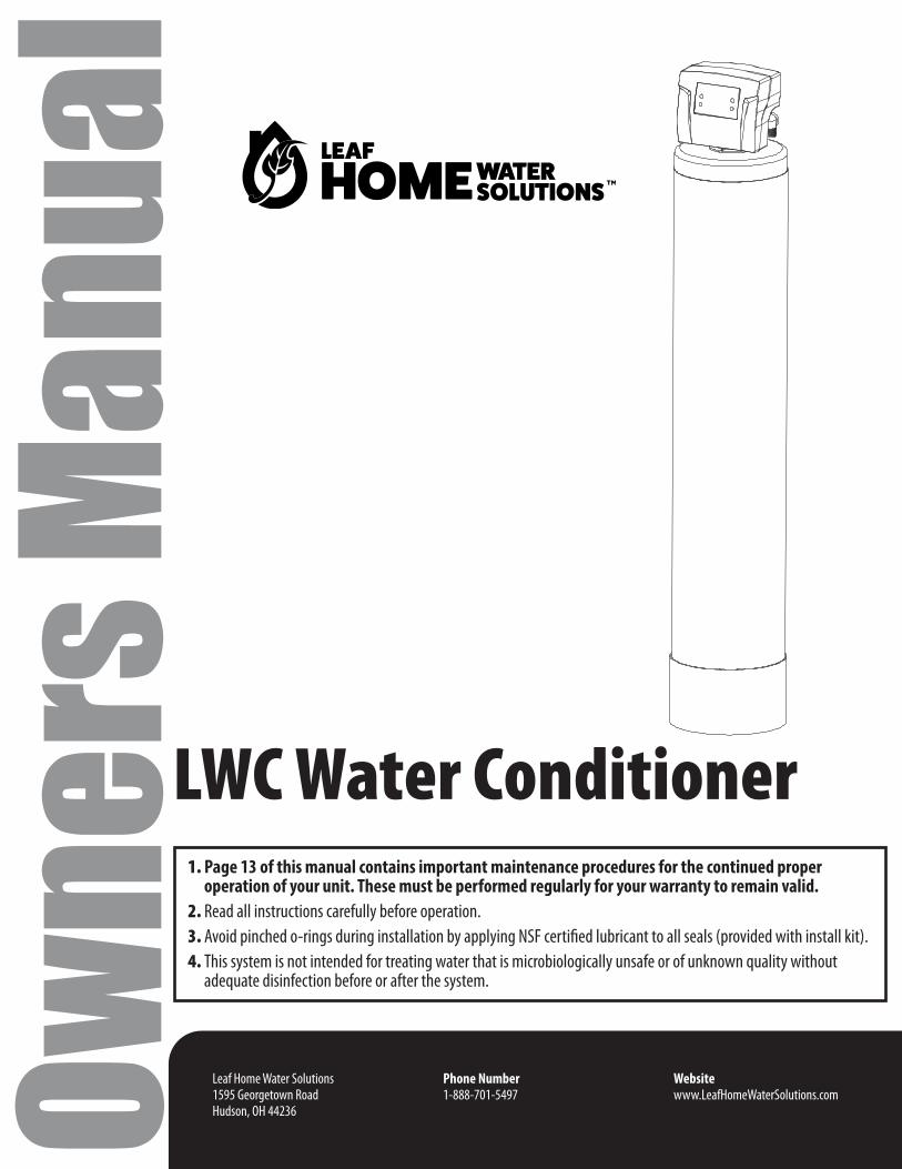
Leaf Home Water Solutions 1595 Georgetown Road Hudson, OH 44236 Phone Number 1-888-701-5497 Website www.LeafHomeWaterSolutions.com Owners Manual LWC Water Conditioner 1. Page 13 of this manual contains important maintenance procedures for the continued proper operation of your unit. These must be performed regularly for your warranty to remain valid. 2. Read all instructions carefully before operation. 3. Avoid pinched o-rings during installation by applying NSF certified lubricant to all seals (provided with install kit). 4. This system is not intended for treating water that is microbiologically unsafe or of unknown quality without adequate disinfection before or after the system.
Transcript of Owners Manual - res.cloudinary.com
Leaf Home Water Solutions1595 Georgetown RoadHudson, OH 44236
Phone Number 1-888-701-5497
Websitewww.LeafHomeWaterSolutions.comOw
ners
Man
ual
LWC Water Conditioner1. Page 13 of this manual contains important maintenance procedures for the continued proper operation of your unit. These must be performed regularly for your warranty to remain valid.2. Read all instructions carefully before operation.3. Avoid pinched o-rings during installation by applying NSF certified lubricant to all seals (provided with install kit).4. This system is not intended for treating water that is microbiologically unsafe or of unknown quality without adequate disinfection before or after the system.
Tabl
e of C
onte
nts
Tabl
e of C
onte
nts READ THIS PAGE FIRST
BEFORE STARTING INSTALLATION 4
SPECIFICATIONS SPECIFICATION 5SYSTEM DIMENSIONS 5
INSTALLATION UNPACKING / INSPECTION 6CHECK VALVE TYPE AND VALVE SERIAL # 7BEFORE INSTALLATION 8PREPARATIONS 9INSTALLATION STEPS 9 WATER CONDITIONER INSTALLATION 11
STARTUP INSTRUCTIONS 12
MAINTENANCE INSTRUCTIONS AND INFORMATION 13
SERVICING CONTROL VALVE 14
REPLACEMENT TIMER REPLACEMENT 14PISTON ASSEMBLY REPLACEMENT 15 CLEAN INJECTOR ASSEMBLY 15 REPLACE MOTOR 16 REPLACE MICROSWITCHES 16CIRCUIT BOARD REPLACEMENT 17 DRAIN WASHER REPLACEMENT 17
AFTER SERVICING 17
PARTS BREAKDOWN 18
PARTS POWERHEAD / BYPASS 19VALVE BODY 20DLFC PART # / BLFC PART # /INJECTOR PART # 21
TROUBLE SHOOTING GUIDE 22
MASTER PROGRAMMING GUIDE 23
DIAGNOSTIC SCREEN 25
4
READ THIS PAGE FIRST BEFORE STARTING INSTALLATION
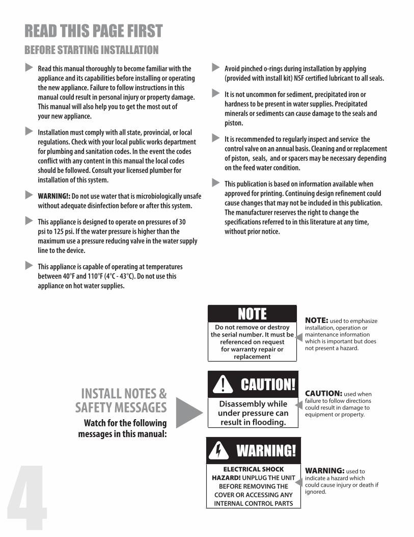
INSTALL NOTES &SAFETY MESSAGES
Watch for the following messages in this manual:
NOTEDo not remove or destroy
the serial number. It must be referenced on request for warranty repair or
replacement
CAUTION!Disassembly while under pressure can result in flooding.
WARNING!ELECTRICAL SHOCK
HAZARD! UNPLUG THE UNIT BEFORE REMOVING THE
COVER OR ACCESSING ANY INTERNAL CONTROL PARTS
NOTE: used to emphasize installation, operation or maintenance information which is important but does not present a hazard.
CAUTION: used when failure to follow directions could result in damage to equipment or property.
WARNING: used to indicate a hazard which could cause injury or death if ignored.
Read this manual thoroughly to become familiar with the appliance and its capabilities before installing or operating the new appliance. Failure to follow instructions in this manual could result in personal injury or property damage. This manual will also help you to get the most out of your new appliance.
Installation must comply with all state, provincial, or local regulations. Check with your local public works department for plumbing and sanitation codes. In the event the codes conflict with any content in this manual the local codes should be followed. Consult your licensed plumber for installation of this system.
WARNING!: Do not use water that is microbiologically unsafe without adequate disinfection before or after this system.
This appliance is designed to operate on pressures of 30 psi to 125 psi. If the water pressure is higher than the maximum use a pressure reducing valve in the water supply line to the device.
This appliance is capable of operating at temperatures between 40°F and 110°F (4°C - 43°C). Do not use this appliance on hot water supplies.
Avoid pinched o-rings during installation by applying (provided with install kit) NSF certified lubricant to all seals.
It is not uncommon for sediment, precipitated iron or hardness to be present in water supplies. Precipitated minerals or sediments can cause damage to the seals and piston.
It is recommended to regularly inspect and service the control valve on an annual basis. Cleaning and or replacement of piston, seals, and or spacers may be necessary depending on the feed water condition.
This publication is based on information available when approved for printing. Continuing design refinement could cause changes that may not be included in this publication. The manufacturer reserves the right to change the specifications referred to in this literature at any time, without prior notice.
4 5A
B
C
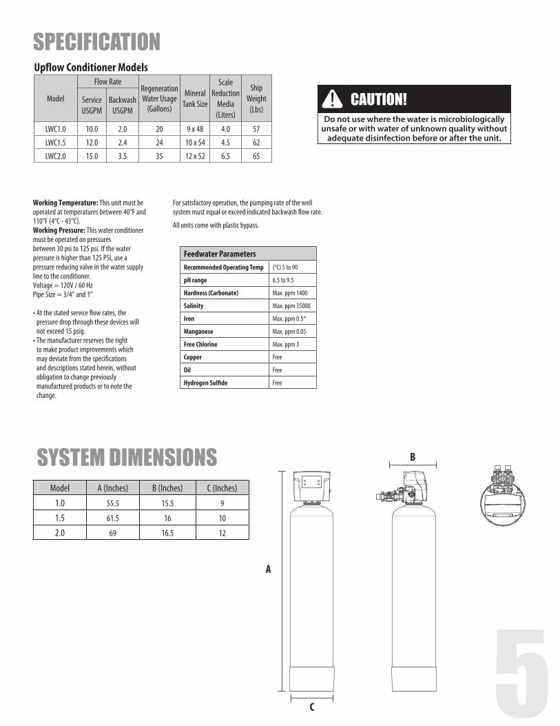
Upflow Conditioner Models
Model
Flow Rate Regeneration Water Usage
(Gallons)
Mineral Tank Size
Scale Reduction
Media(Liters)
Ship Weight
(Lbs)Service USGPM
Backwash USGPM
LWC1.0 10.0 2.0 20 9 x 48 4.0 57
LWC1.5 12.0 2.4 24 10 x 54 4.5 62
LWC2.0 15.0 3.5 35 12 x 52 6.5 65
Model A (Inches) B (Inches) C (Inches)1.0 55.5 15.5 9
1.5 61.5 16 10
2.0 69 16.5 12
Feedwater ParametersRecommended Operating Temp (°C) 5 to 90
pH range 6.5 to 9.5
Hardness (Carbonate) Max. ppm 1400
Salinity Max. ppm 35000
Iron Max. ppm 0.5*
Manganese Max. ppm 0.05
Free Chlorine Max. ppm 3
Copper Free
Oil Free
Hydrogen Sulfide Free
SPECIFICATION
SYSTEM DIMENSIONS
Working Temperature: This unit must be operated at temperatures between 40°F and 110°F (4°C - 43°C). Working Pressure: This water conditioner must be operated on pressures between 30 psi to 125 psi. If the water pressure is higher than 125 PSI, use a pressure reducing valve in the water supply line to the conditioner. Voltage = 120V / 60 HzPipe Size = 3/4” and 1”
• At the stated service flow rates, the pressure drop through these devices will not exceed 15 psig.
• The manufacturer reserves the right to make product improvements which may deviate from the specifications and descriptions stated herein, without obligation to change previously manufactured products or to note the change.
For satisfactory operation, the pumping rate of the well system must equal or exceed indicated backwash flow rate.
All units come with plastic bypass.
CAUTION!Do not use where the water is microbiologically
unsafe or with water of unknown quality without adequate disinfection before or after the unit.
6
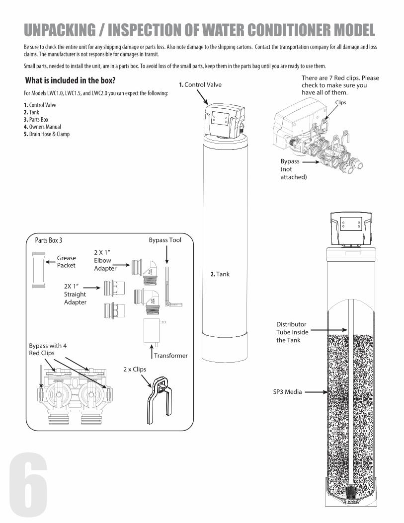
There are 7 Red clips. Please check to make sure you have all of them.
Distributor Tube Inside the Tank
SP3 Media
Clips
1. Control Valve
Parts Box 3
2X 1” Straight Adapter
Bypass Tool
2 X 1” Elbow Adapter
Transformer
Grease Packet
Bypass with 4 Red Clips
2 x Clips
Be sure to check the entire unit for any shipping damage or parts loss. Also note damage to the shipping cartons. Contact the transportation company for all damage and loss claims. The manufacturer is not responsible for damages in transit.
Small parts, needed to install the unit, are in a parts box. To avoid loss of the small parts, keep them in the parts bag until you are ready to use them.
What is included in the box?For Models LWC1.0, LWC1.5, and LWC2.0 you can expect the following:
1. Control Valve 2. Tank 3. Parts Box 4. Owners Manual 5. Drain Hose & Clamp
UNPACKING / INSPECTION OF WATER CONDITIONER MODEL
2. Tank
Bypass (not attached)
6 7
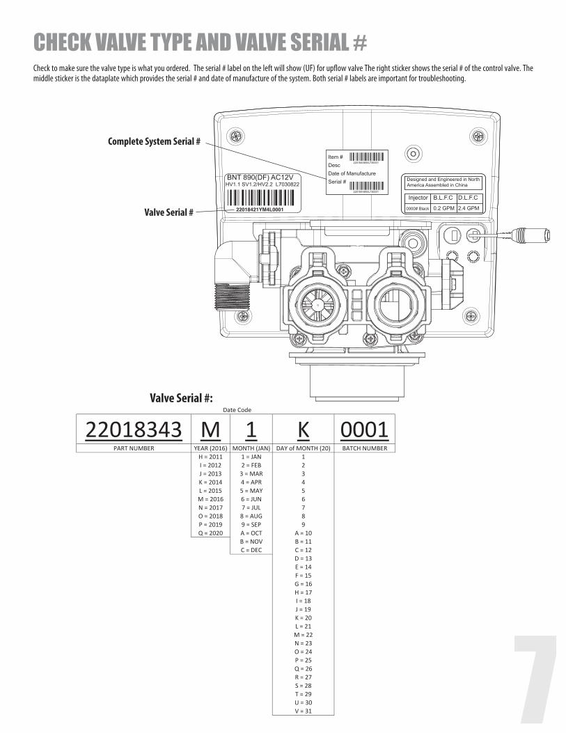
CHECK VALVE TYPE AND VALVE SERIAL #
Check to make sure the valve type is what you ordered. The serial # label on the left will show (UF) for upflow valve The right sticker shows the serial # of the control valve. The middle sticker is the dataplate which provides the serial # and date of manufacture of the system. Both serial # labels are important for troubleshooting.
Valve Serial #
Complete System Serial #Item #DescDate of ManufactureSerial #
22018343 M 1 K 0001PART NUMBER YEAR (2016) MONTH (JAN) DAY of MONTH (20) BATCH NUMBER
H = 2011 1 = JAN 1I = 2012 2 = FEB 2J = 2013 3 = MAR 3K = 2014 4 = APR 4L = 2015 5 = MAY 5M = 2016 6 = JUN 6N = 2017 7 = JUL 7O = 2018 8 = AUG 8P = 2019 9 = SEP 9Q = 2020 A = OCT A = 10
B = NOV B = 11C = DEC C = 12
D = 13E = 14F = 15G = 16H = 17I = 18J = 19K = 20L = 21M = 22N = 23O = 24P = 25Q = 26R = 27S = 28T = 29U = 30V = 31
Date Code Valve Serial #:
8
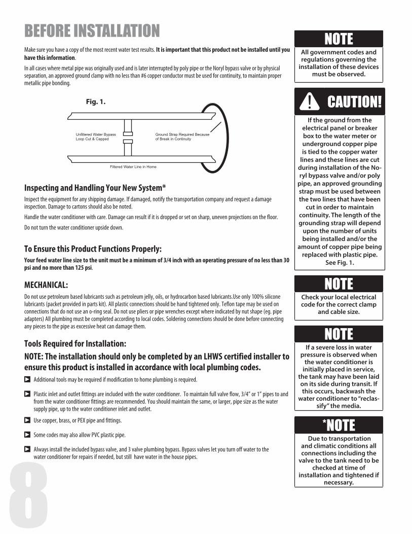
Fig. 1.
BEFORE INSTALLATIONMake sure you have a copy of the most recent water test results. It is important that this product not be installed until you have this information.
In all cases where metal pipe was originally used and is later interrupted by poly pipe or the Noryl bypass valve or by physical separation, an approved ground clamp with no less than #6 copper conductor must be used for continuity, to maintain proper metallic pipe bonding.
Inspecting and Handling Your New System* Inspect the equipment for any shipping damage. If damaged, notify the transportation company and request a damage inspection. Damage to cartons should also be noted.
Handle the water conditioner with care. Damage can result if it is dropped or set on sharp, uneven projections on the floor.
Do not turn the water conditioner upside down.
To Ensure this Product Functions Properly:Your feed water line size to the unit must be a minimum of 3/4 inch with an operating pressure of no less than 30 psi and no more than 125 psi.
MECHANICAL: Do not use petroleum based lubricants such as petroleum jelly, oils, or hydrocarbon based lubricants.Use only 100% silicone lubricants (packet provided in parts kit). All plastic connections should be hand tightened only. Teflon tape may be used on connections that do not use an o-ring seal. Do not use pliers or pipe wrenches except where indicated by nut shape (eg. pipe adapters) All plumbing must be completed according to local codes. Soldering connections should be done before connecting any pieces to the pipe as excessive heat can damage them.
Tools Required for Installation:NOTE: The installation should only be completed by an LHWS certified installer to ensure this product is installed in accordance with local plumbing codes.sAdditional tools may be required if modification to home plumbing is required.
sPlastic inlet and outlet fittings are included with the water conditioner. To maintain full valve flow, 3/4” or 1” pipes to and from the water conditioner fittings are recommended. You should maintain the same, or larger, pipe size as the water supply pipe, up to the water conditioner inlet and outlet.
sUse copper, brass, or PEX pipe and fittings.
sSome codes may also allow PVC plastic pipe.
sAlways install the included bypass valve, and 3 valve plumbing bypass. Bypass valves let you turn off water to the water conditioner for repairs if needed, but still have water in the house pipes.
NOTEAll government codes and regulations governing the
installation of these devices must be observed.
NOTEIf a severe loss in water
pressure is observed when the water conditioner is
initially placed in service, the tank may have been laid on its side during transit. If this occurs, backwash the
water conditioner to “reclas-sify” the media.
*NOTE Due to transportation
and climatic conditions all connections including the
valve to the tank need to be checked at time of
installation and tightened if necessary.
NOTECheck your local electrical code for the correct clamp
and cable size.
CAUTION!If the ground from the
electrical panel or breaker box to the water meter or underground copper pipe is tied to the copper water
lines and these lines are cut during installation of the No-ryl bypass valve and/or poly
pipe, an approved grounding strap must be used between the two lines that have been
cut in order to maintain continuity. The length of the grounding strap will depend
upon the number of units being installed and/or the
amount of copper pipe being replaced with plastic pipe.
See Fig. 1.
8 9
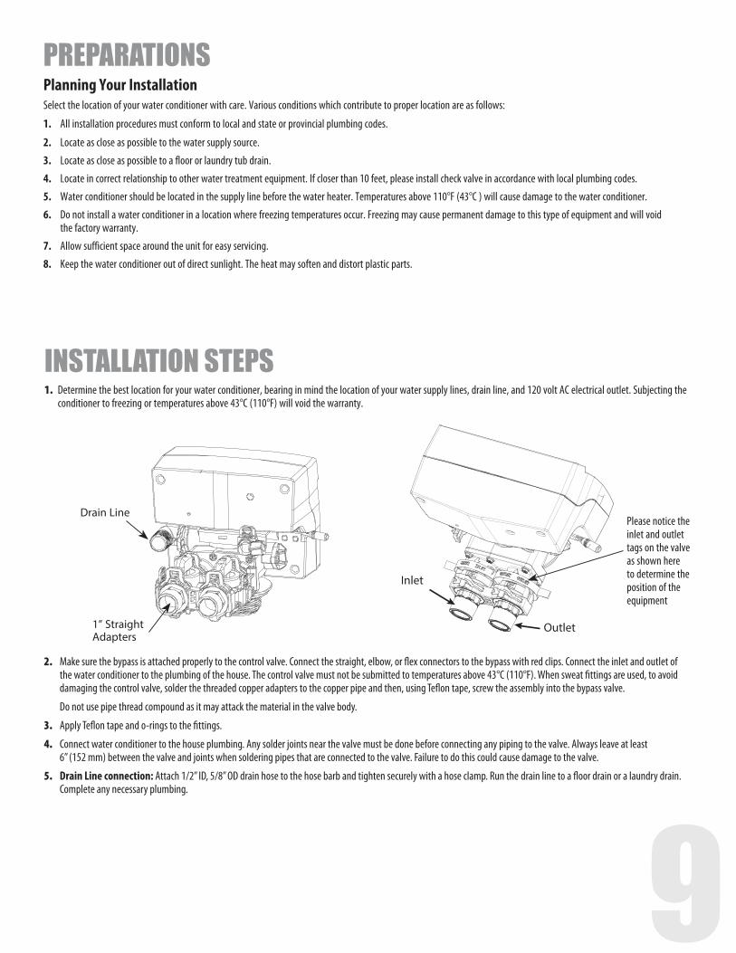
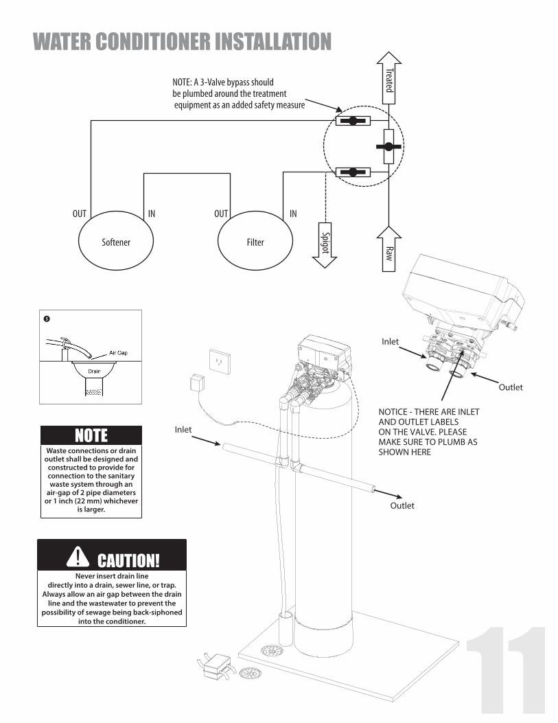
Inlet
Outlet
Please notice the inlet and outlet tags on the valve as shown here to determine the position of the equipment
1” Straight Adapters
Drain Line
PREPARATIONSPlanning Your Installation Select the location of your water conditioner with care. Various conditions which contribute to proper location are as follows:
1. All installation procedures must conform to local and state or provincial plumbing codes.
2. Locate as close as possible to the water supply source.
3. Locate as close as possible to a floor or laundry tub drain.
4. Locate in correct relationship to other water treatment equipment. If closer than 10 feet, please install check valve in accordance with local plumbing codes.
5. Water conditioner should be located in the supply line before the water heater. Temperatures above 110°F (43°C ) will cause damage to the water conditioner.
6. Do not install a water conditioner in a location where freezing temperatures occur. Freezing may cause permanent damage to this type of equipment and will void the factory warranty.
7. Allow sufficient space around the unit for easy servicing.
8. Keep the water conditioner out of direct sunlight. The heat may soften and distort plastic parts.
2. Make sure the bypass is attached properly to the control valve. Connect the straight, elbow, or flex connectors to the bypass with red clips. Connect the inlet and outlet of the water conditioner to the plumbing of the house. The control valve must not be submitted to temperatures above 43°C (110°F). When sweat fittings are used, to avoid damaging the control valve, solder the threaded copper adapters to the copper pipe and then, using Teflon tape, screw the assembly into the bypass valve.
Do not use pipe thread compound as it may attack the material in the valve body.
3. Apply Teflon tape and o-rings to the fittings.
4. Connect water conditioner to the house plumbing. Any solder joints near the valve must be done before connecting any piping to the valve. Always leave at least 6” (152 mm) between the valve and joints when soldering pipes that are connected to the valve. Failure to do this could cause damage to the valve.
5. Drain Line connection: Attach 1/2” ID, 5/8” OD drain hose to the hose barb and tighten securely with a hose clamp. Run the drain line to a floor drain or a laundry drain. Complete any necessary plumbing.
1. Determine the best location for your water conditioner, bearing in mind the location of your water supply lines, drain line, and 120 volt AC electrical outlet. Subjecting the conditioner to freezing or temperatures above 43°C (110°F) will void the warranty.
INSTALLATION STEPS
10
INSTALLATION STEPS
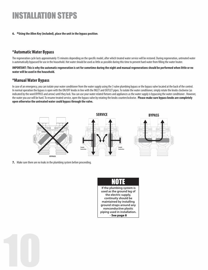
6. *Using the Allen Key (included), place the unit in the bypass position.
7. Make sure there are no leaks in the plumbing system before proceeding.
*Automatic Water BypassThe regeneration cycle lasts approximately 15 minutes depending on the specific model, after which treated water service will be restored. During regeneration, untreated water is automatically bypassed for use in the household. Hot water should be used as little as possible during this time to prevent hard water from filling the water heater.
IMPORTANT: This is why the automatic regeneration is set for sometime during the night and manual regenerations should be performed when little or no water will be used in the household.
*Manual Water BypassIn case of an emergency, you can isolate your water conditioner from the water supply using the 3 valve plumbing bypass or the bypass valve located at the back of the control. In normal operation the bypass is open with the ON/OFF knobs in line with the INLET and OUTLET pipes. To isolate the water conditioner, simply rotate the knobs clockwise (as indicated by the word BYPASS and arrow) until they lock. You can use your water related fixtures and appliances as the water supply is bypassing the water conditioner . However, the water you use will be hard. To resume treated service, open the bypass valve by rotating the knobs counterclockwise. Please make sure bypass knobs are completely open otherwise the untreated water could bypass through the valve.
NOTE If the plumbing system is used as the ground leg of
the electric supply, continuity should be
maintained by installing ground straps around any
nonconductive plastic piping used in installation.
- See page 8
SampleConnection
SampleConnection
SERVICE
BYPASS
SampleConnection
SampleConnection
SERVICE
BYPASS
BYPASS
10 11
5
Inlet
Outlet
Inlet
NOTICE - THERE ARE INLET AND OUTLET LABELS ON THE VALVE. PLEASE MAKE SURE TO PLUMB AS SHOWN HERE
Outlet
NOTE: A 3-Valve bypass should be plumbed around the treatment equipment as an added safety measure
OUT
Softener FilterSpigot
TreatedRaw
IN OUT IN
WATER CONDITIONER INSTALLATION
CAUTION!Never insert drain line
directly into a drain, sewer line, or trap. Always allow an air gap between the drain
line and the wastewater to prevent the possibility of sewage being back-siphoned
into the conditioner.
NOTEWaste connections or drain
outlet shall be designed and constructed to provide for connection to the sanitary waste system through an
air-gap of 2 pipe diameters or 1 inch (22 mm) whichever
is larger.
12
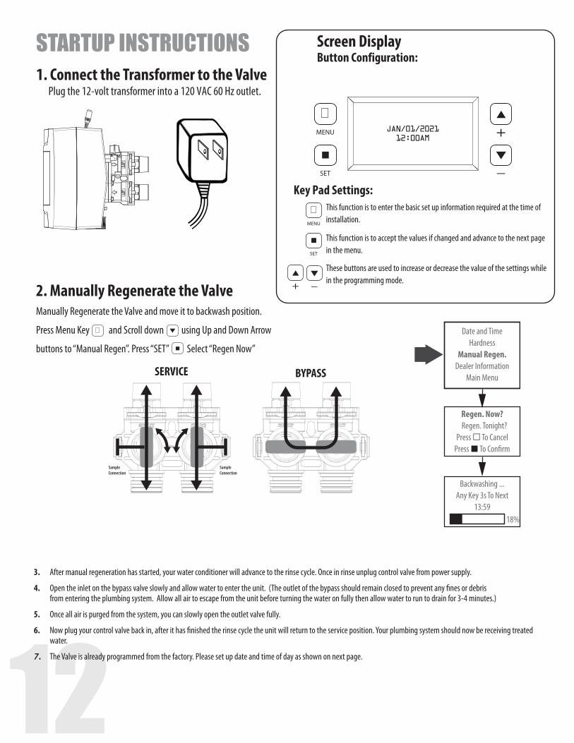
STARTUP INSTRUCTIONS Screen Display Button Configuration:
MENU
SET
JAN/01/2021 12:00AM
MENU
SET
MENU
SET
MENU
SET
MENU
SET
This function is to accept the values if changed and advance to the next page in the menu.
These buttons are used to increase or decrease the value of the settings while in the programming mode.
This function is to enter the basic set up information required at the time of installation.
Key Pad Settings:
SampleConnection
SampleConnection
SERVICE
BYPASS
SampleConnection
SampleConnection
SERVICE
BYPASS
Date and TimeHardness
Manual Regen.Dealer Information
Main Menu
Regen. Now?Regen. Tonight?
Press To CancelPress To Con�rm
Backwashing ...Any Key 3s To Next
13:5918%
1. Connect the Transformer to the Valve Plug the 12-volt transformer into a 120 VAC 60 Hz outlet.
2. Manually Regenerate the ValveManually Regenerate the Valve and move it to backwash position.
Press Menu Key MENU
SET
and Scroll down MENU
SET using Up and Down Arrow
buttons to “Manual Regen”. Press “SET” MENU
SET
Select “Regen Now”
3. After manual regeneration has started, your water conditioner will advance to the rinse cycle. Once in rinse unplug control valve from power supply.
4. Open the inlet on the bypass valve slowly and allow water to enter the unit. (The outlet of the bypass should remain closed to prevent any fines or debris from entering the plumbing system. Allow all air to escape from the unit before turning the water on fully then allow water to run to drain for 3-4 minutes.)
5. Once all air is purged from the system, you can slowly open the outlet valve fully.
6. Now plug your control valve back in, after it has finished the rinse cycle the unit will return to the service position. Your plumbing system should now be receiving treated water.
7. The Valve is already programmed from the factory. Please set up date and time of day as shown on next page.
12 13
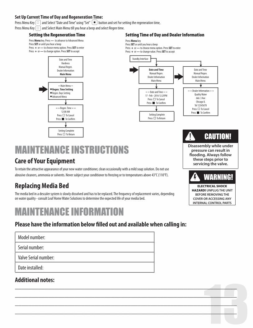
Setting Complete Press¨ To Return
= Main Menu = n Regen. Time Setting n Regen. Days Setting n Advanced Menu
= = Regen. Time = = 12:00 AM
Press¨ To Cancel Pressn To Confirm
Date and TimeHardness
Manual Regen. Dealer Information
Main Menu
Setting the Regeneration TimePress Menu key. Press — to advance to Advanced Menu Press SET or until you hear a beep Press + or — to choose menu option. Press SET to enter Press + or — to change option. Press SET to accept
= = Dealer Information = =Quality Water
666 3 Ave Chicago IL
Tel 12345678 Press¨ To Cancel
Pressn To Confirm
Standby Interface
Setting Complete Press¨ To Return
Date and Time Manual Regen.
Dealer Information Main Menu
Date and Time Manual Regen.
Dealer Information Main Menu
= = Date and Time = = 17 - Feb - 2016 12:25PM
Press¨ To Cancel Pressn To Confirm
Setting Time of Day and Dealer InformationPress Menu key Press SET or until you hear a beep Press + or — to choose menu option. Press SET to enter Press + or — to change value. Press SET to accept
Set Up Current Time of Day and Regeneration Time:Press Menu Key
MENU
SET
and Select “Date and Time” using “Set”
MENU
SET
button and set For setting the regeneration time, Press Menu Key
MENU
SET
and Select Main Menu till you hear a beep and select Regen time.
Care of Your EquipmentTo retain the attractive appearance of your new water conditioner, clean occasionally with a mild soap solution. Do not use abrasive cleaners, ammonia or solvents. Never subject your conditioner to freezing or to temperatures above 43°C (110°F). Replacing Media BedThe media bed in a descaler system is slowly dissolved and has to be replaced. The frequency of replacement varies, depending on water quality - consult Leaf Home Water Solutions to determine the expected life of your media bed.
MAINTENANCE INSTRUCTIONSCAUTION!
Disassembly while under pressure can result in
flooding. Always follow these steps prior to servicing the valve.
WARNING!ELECTRICAL SHOCK
HAZARD! UNPLUG THE UNIT BEFORE REMOVING THE
COVER OR ACCESSING ANY INTERNAL CONTROL PARTS
MAINTENANCE INFORMATION
Model number:
Serial number:
Valve Serial number:
Date installed:
Please have the information below filled out and available when calling in:
Additional notes:____________________________________________________________________________________________________________________________________________________________________________________________________________________________________________________________________________
14
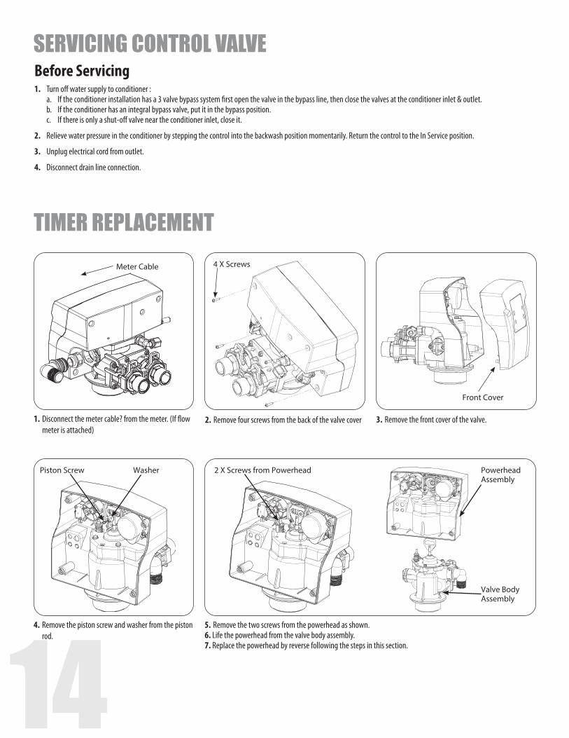
Meter Cable 4 X Screws
Front Cover
1. Disconnect the meter cable? from the meter. (If flow meter is attached)
2. Remove four screws from the back of the valve cover 3. Remove the front cover of the valve.
4. Remove the piston screw and washer from the piston rod.
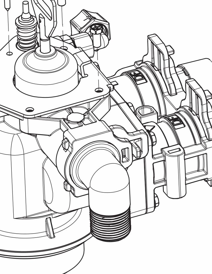
5. Remove the two screws from the powerhead as shown.6. Life the powerhead from the valve body assembly.7. Replace the powerhead by reverse following the steps in this section.
Piston Screw 2 X Screws from PowerheadWasher Powerhead Assembly
Valve Body Assembly
TIMER REPLACEMENT
Before Servicing1. Turn off water supply to conditioner : a. If the conditioner installation has a 3 valve bypass system first open the valve in the bypass line, then close the valves at the conditioner inlet & outlet. b. If the conditioner has an integral bypass valve, put it in the bypass position. c. If there is only a shut-off valve near the conditioner inlet, close it.
2. Relieve water pressure in the conditioner by stepping the control into the backwash position momentarily. Return the control to the In Service position.
3. Unplug electrical cord from outlet.
4. Disconnect drain line connection.
SERVICING CONTROL VALVE
14 15
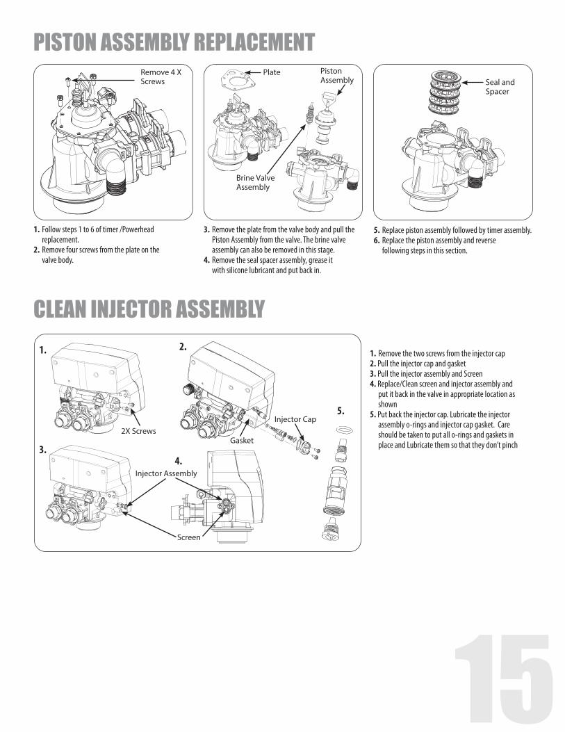
1. Follow steps 1 to 6 of timer /Powerhead replacement.
2. Remove four screws from the plate on the valve body.
3. Remove the plate from the valve body and pull the Piston Assembly from the valve. The brine valve assembly can also be removed in this stage.
4. Remove the seal spacer assembly, grease it with silicone lubricant and put back in.
5. Replace piston assembly followed by timer assembly.6. Replace the piston assembly and reverse
following steps in this section.
Remove 4 X Screws
PlateSeal and Spacer
Brine Valve Assembly
Piston Assembly
Screen
1.
3.
5.
2.
4.
2X ScrewsGasket
Injector Cap
Injector Assembly
PISTON ASSEMBLY REPLACEMENT
CLEAN INJECTOR ASSEMBLY1. Remove the two screws from the injector cap2. Pull the injector cap and gasket3. Pull the injector assembly and Screen4. Replace/Clean screen and injector assembly and put it back in the valve in appropriate location as shown5. Put back the injector cap. Lubricate the injector assembly o-rings and injector cap gasket. Care should be taken to put all o-rings and gaskets in place and Lubricate them so that they don’t pinch
16
2. 1.
4X Screws
4. 2 X Motor Screws
3.
Wire connection to Circuit Board
Circuit Board
REPLACE MICROSWITCHES
1.
Cover 4X Screws
4.
Microswitch
MicroswitchScrews
3.
Wire connections to Circuit Board
2. Front Cover
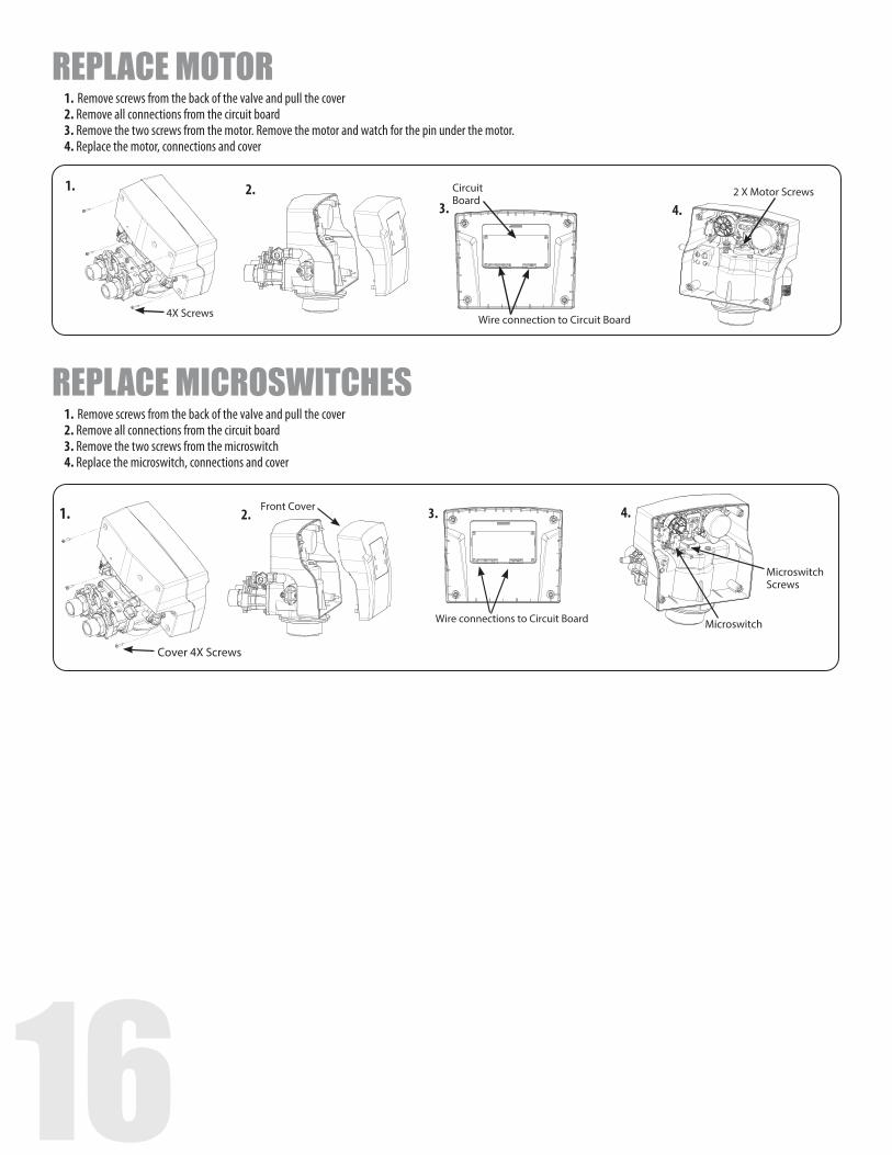
REPLACE MOTOR1. Remove screws from the back of the valve and pull the cover2. Remove all connections from the circuit board3. Remove the two screws from the motor. Remove the motor and watch for the pin under the motor.4. Replace the motor, connections and cover
1. Remove screws from the back of the valve and pull the cover2. Remove all connections from the circuit board3. Remove the two screws from the microswitch4. Replace the microswitch, connections and cover
16 17
Drain elbow
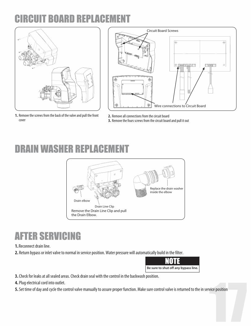
Drain Line ClipRemove the Drain Line Clip and pull the Drain Elbow.
Replace the drain washer inside the elbow
AFTER SERVICING
DRAIN WASHER REPLACEMENT
1. Reconnect drain line.2. Return bypass or inlet valve to normal in service position. Water pressure will automatically build in the filter.
3. Check for leaks at all sealed areas. Check drain seal with the control in the backwash position.4. Plug electrical cord into outlet.5. Set time of day and cycle the control valve manually to assure proper function. Make sure control valve is returned to the in service position
NOTEBe sure to shut off any bypass line.
CIRCUIT BOARD REPLACEMENT
Wire connections to Circuit Board
Circuit Board Screws
1. Remove the screws from the back of the valve and pull the front cover
2. Remove all connections from the circuit board3. Remove the fours screws from the circuit board and pull it out
18
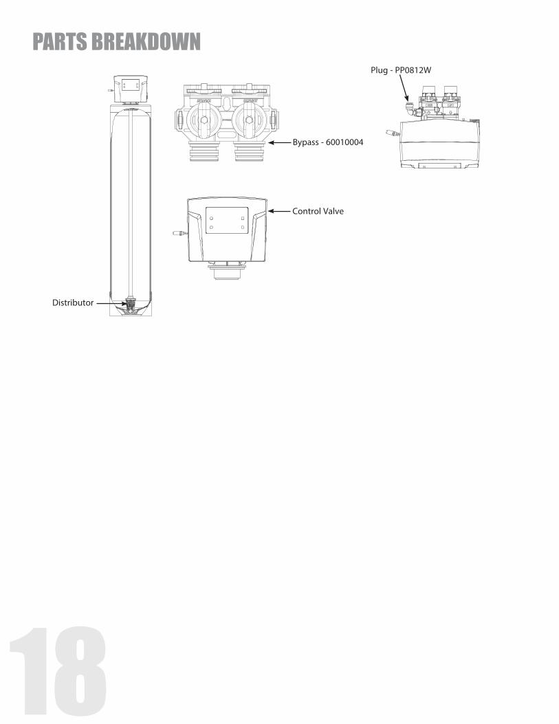
Control Valve
Distributor
Bypass - 60010004
Plug - PP0812W
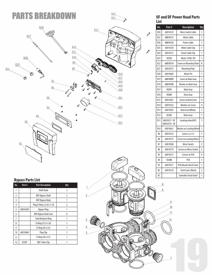
PARTS BREAKDOWN
18 197
8
6
11
1
2
9
5
10
3
4
12
Bypass Parts ListNo. Part # Part Description Qty
1 Shaft Knob 2
2 BNT Bypass Shaft 2
3 BNT Bypass Body 1
4 Plug O-Ring 12.42×1.78 2
5 60010209 Bypass Plug 1
6 BNT Bypass Knob Seal 8
7 Steel Retainer Ring 1
8 O-Ring 35.5×2.65 1
9 O-Ring 30×2.65 1
10 60010069 Plug Clip 1
11 O-Ring 30×3.55 1
12 92387 BNT Valve Clip 1
UF and DF Power Head Parts List
No. Part # Description Qty
B28 60010329 Micro Switch Cable 1
B27 60010115 Meter Cable 1
B26 60010124 Power Cable 1
B25 60010330 Meter Cable Clip 1
B24 60010331 Power Cable Clip 1
B23 92393 Motor 12VAC 3W 1
B22 60010574 Screw on Mounting Plate 8
B21 60010573 Mounting Plate 1
B20 60010660 Motor Pin 1
B19 60010099 Screw on Main Gear 1
B18 60010100 Washer on Main Gear 1
B17 92391 Main Gear 1
B16 92389 Drive Gear 1
B15 60010581 Screw on Back Cover 4
B14 60010332 Washers on Screw 4
B13 60010582 Back Cover(Black) 1
B12 92392 Brine Gear 1
B11 60010577 -UF 60010576 - DF
Locating wheel(UF) 1
B10 60010661 Washer on Locating Wheel 1
B9 60010333 Screw 2.2×13 1
B8 60010575 Screw on Locating Wheel 1
B7 60010580 Micro Switch 2
B6 60010579 Screws on Micro Switch 2
B5 60010572 Screws on PCB 4
B4 92388 PCB 1
B3 60010571 PCB Absorb Shock Foam 1
B2 60010570 Front Cover (Black) 1
B1 Controller Touch Panel 1
PARTS BREAKDOWN
20
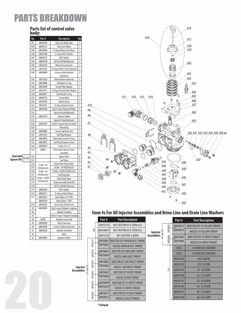
Item #s For All Injector Assemblies and Brine Line and Drain Line WashersPart # Part Description
60010110 BLFC BUTTON #2 0.3GPM A32
60010082* BLFC BUTTON #2 0.7GPM A32
60010128 BLFC BUTTON 0.2GPM
60010601 60010602
INJECTOR SET #0000 BLACK THROAT
NOZZLE #0000 BLACK THROAT
6001060360010604
INJECTOR SET #000 GREY THROAT
NOZZLE #000 GREY THROAT
60010605 60010606
INJECTOR SET #00 VIOLET THROAT
NOZZLE #00 VIOLET THROAT
60010607 60010608
INJECTOR SET #0 RED THROAT
NOZZLE #0 RED THROAT
60010609* 60010610*
INJECTOR SET #1 WHITE THROAT
NOZZLE #1 WHITE THROAT
60010611 60010612
INJECTOR SET #2 BLUE THROAT
NOZZLE #2 BLUE THROAT
A46
A31 a
nd A3
3
* Default
Injector Assemblies
6001
0127
6001
0126
6001
0032
6001
0033
6001
0034
6001
0035
Part # Part Description60010613 60010614
INJECTOR SET #3 YELLOW THROAT
NOZZLE #3 YELLOW THROAT
6001068560010686
INJECTOR SET #4 GREEN THROAT
NOZZLE #4 GREEN THROAT
12052 1.4 GPM DLFC WASHER
12053 2.0 GPM DLFC WASHER
60010140 #4S 5.0GPM
60010142 #7S 7.0 GPM
60010143 #1 8.0 GPM
60010144 #2 11.0 GPM
60010145 #3 14.0 GPM
60010146 #4 17.0 GPM
60010147 #5 21.0 GPM
60010148 #6 24.0 GPM
A31 a
nd A3
3
A14
Injector Assemblies
6001
0031
6001
0686
Parts list of control valve body:
No. Part # Description QtyA51 60010184 Brine Line Elbow Nut 1A50 60010172 Brine Line Elbow 1A49 60010044 O-ring of Brine Line Elbow 1A48 60010188 O-ring of BLFC Holder 1A47 60010173 BLFC Holder 2A46 60010128 BLFC(0.2GPM)(Optional) 1A45 60010340 Brine Line Connector 1A44 60010265 O-ring on Brine Line Connector 1A43 60010099 Screw on Valve Bottom
Connector2
A42 60010599 Valve Bottom Connector 1A41 60010080 Distributor O-ring 1A40 60010598 Central Pipe Adaptor 1A39 60010597 O-ring of Central Pipe Adaptor 1A38 60010077 Tank Mouth O-ring 1A37 60010715 Screen Valve 1A36 60010595 Injector Cover 1A35 60010341 O-ring of Injector Cover 1A34 60010186 Big O-ring of Injector Holder 1A33 Injector Nozzle(Optional) 1A32 60010174 Injector Holder 1A31 Injector Throat(Optional) 1A30 60010187 Small O-ring of Injector Holder 1A29 Valve Body 1A28 60010069 Secure Clip Brine Line 1A27 60010343 End Plug Retainer 1A26 60010076 Valve Body Connect Screws 2A25 60010075 End Plug Retainer Screws 3A24 60010574 Screw 3.5×13 1A23 60032 Brine Valve Injector Stem
Assembly1
A22 Spacer Valve 8A21 Seal Valve 5A20 92383 - DF
PISTON ASSY 92384 - UP
PISTON ASSY92385 - FILTER PISTON ASSY
Down Flow Piston Valve 1A19 92384 - UP PISTON ASSY 1A18 92385 - FILTER PISTON ASSY 1A17 End Plug Valve 1A16 Piston Rod Valve 1A15 Piston Assembly Valve(DF) 1A14 DLFC(2.4GPM)(Optional) 1A13 60095694 DLFC Holder 1A12 60010211 O-ring on Drain Elbow 1A11 60010253 Drain Elbow 3/4” NPT 1
60010254 Drain Elbow 1” NPT 1A10 60010227 Secure Clip of Drain Line 1A9 60010585 Big O-ring of Adaptor Coupling 2A8 Adaptor Coupling 2A7 Small O-ring of Adaptor Coupling 2A6 92387 Adaptor Secure Clip 2A5 60010589 Valve Connector 1A4 60010596 Screws of Valve Connector 8A3 60010238 Impeller Assembly 1A2 Bush 2A1 60010587 Impeller Holder 1
Seal and Spacer Kit 92382
PARTS BREAKDOWN
20 21
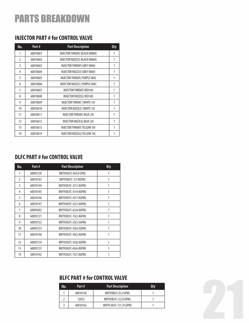
DLFC PART # for CONTROL VALVENo. Part # Part Description Qty
1 60095720 BNT95DLFC-0(4.0 GPM) 1
2 60010143 BNT95DLFC-1(7.0GPM) 1
3 60010144 BNT95DLFC-2(11.0GPM) 1
4 60010145 BNT95DLFC-3(14.0GPM) 1
5 60010146 BNT95DLFC-4(17.0GPM) 1
6 60010147 BNT95DLFC-5(21.0GPM) 1
7 60095692 BNT95DLFC-6(24.0GPM) 1
8 60095721 BNT95DLFC-1S(2.4GPM) 1
9 60095722 BNT95DLFC-2S(3.5GPM) 1
10 60095723 BNT95DLFC-3S(4.5GPM) 1
11 60010140 BNT95DLFC-4S(5.0GPM) 1
12 60095724 BNT95DLFC-5S(6.0GPM) 1
13 60095725 BNT95DLFC-6S(6.0GPM) 1
14 60010142 BNT95DLFC-7S(7.0GPM) 1
BLFC PART # for CONTROL VALVENo. Part # Part Description Qty
1 60010128 BNT95BLFC (0.2 GPM) 1
2 12053 BNT95BLFC-1(2.0 GPM) 1
3 60010162 BNT95 BLFC-7(1.35 GPM) 1
INJECTOR PART # for CONTROL VALVENo. Part # Part Description Qty
1 60010601 INJECTOR THROAT( BLACK 0000#) 1
2 60010602 INJECTOR NOZZLE( BLACK 0000#) 1
3 60010603 INJECTOR THROAT( GREY 000#) 1
4 60010604 INJECTOR NOZZLE( GREY 000#) 1
5 60010605 INJECTOR THROAT( PURPLE 00#) 1
6 60010606 INJECTOR NOZZLE ( PURPLE 00#) 1
7 60010607 INJECTOR THROAT( RED 0#) 1
8 60010608 INJECTOR NOZZLE( RED 0#) 1
9 60010609 INJECTOR THROAT ( WHITE 1#) 1
10 60010610 INJECTOR NOZZLE ( WHITE 1#) 1
11 60010611 INJECTOR THROAT( BLUE 2#) 1
12 60010612 INJECTOR NOZZLE( BLUE 2#) 1
13 60010613 INJECTOR THROAT( YELLOW 3#) 1
14 60010614 INJECTOR NOZZLE( YELLOW 3#) 1
PARTS BREAKDOWN
22
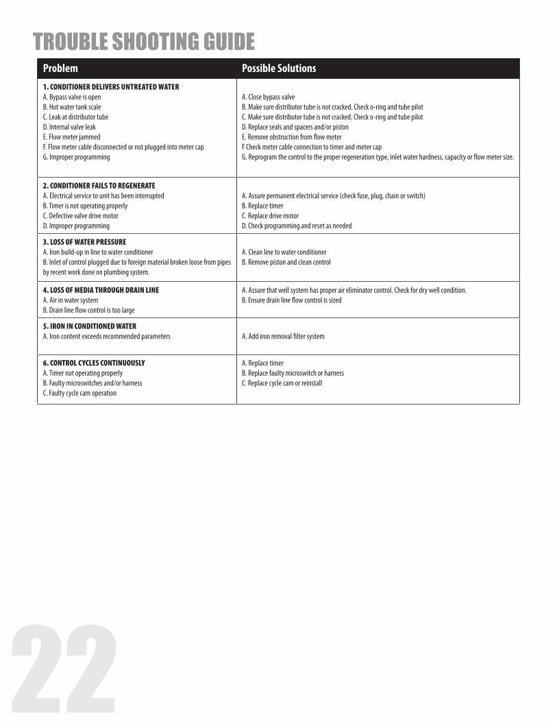
Problem Possible Solutions1. CONDITIONER DELIVERS UNTREATED WATER A. Bypass valve is open B. Hot water tank scale C. Leak at distributor tube D. Internal valve leak E. Flow meter jammed F. Flow meter cable disconnected or not plugged into meter cap G. Improper programming
A. Close bypass valve B. Make sure distributor tube is not cracked. Check o-ring and tube pilot C. Make sure distributor tube is not cracked. Check o-ring and tube pilot D. Replace seals and spacers and/or piston E. Remove obstruction from flow meter F Check meter cable connection to timer and meter cap G. Reprogram the control to the proper regeneration type, inlet water hardness, capacity or flow meter size.
2. CONDITIONER FAILS TO REGENERATE A. Electrical service to unit has been interrupted B. Timer is not operating properly C. Defective valve drive motor D. Improper programming
A. Assure permanent electrical service (check fuse, plug, chain or switch) B. Replace timer C. Replace drive motor D. Check programming and reset as needed
3. LOSS OF WATER PRESSURE A. Iron build-up in line to water conditioner B. Inlet of control plugged due to foreign material broken loose from pipes by recent work done on plumbing system.
A. Clean line to water conditioner B. Remove piston and clean control
4. LOSS OF MEDIA THROUGH DRAIN LINE A. Air in water system B. Drain line flow control is too large
A. Assure that well system has proper air eliminator control. Check for dry well condition. B. Ensure drain line flow control is sized
5. IRON IN CONDITIONED WATER A. Iron content exceeds recommended parameters
A. Add iron removal filter system
6. CONTROL CYCLES CONTINUOUSLY A. Timer not operating properly B. Faulty microswitches and/or harness C. Faulty cycle cam operation
A. Replace timer B. Replace faulty microswitch or harness C. Replace cycle cam or reinstall
TROUBLE SHOOTING GUIDE
22 23
PRESS ‘+’ AND ‘-’ FOR 8 SECONDS
PRESS MENU KEY AND SCROLL TO ‘MAIN
MENU’. THEN PRESS ‘SET’ TILL IT BEEPS
VALVE SETTINGS
MODELS LANGUAGE REGION VALVE METER RATIO
SALT VS EFFICIENCY
AUTO CALCULATION
REGEN. MODE
RINSE DURATION
REGEN TIME
SETTING
REGEN DAY
SETTING
Injector Injector Color
BLFC Washer
DLFC Washer
DLFC Washer
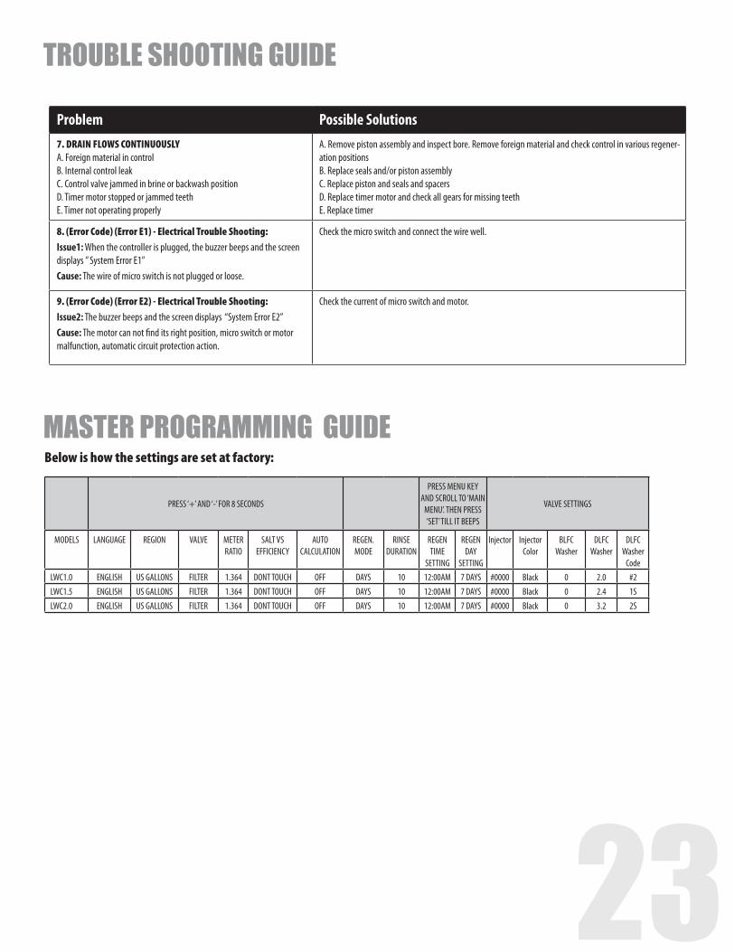
CodeLWC1.0 ENGLISH US GALLONS FILTER 1.364 DONT TOUCH OFF DAYS 10 12:00AM 7 DAYS #0000 Black 0 2.0 #2LWC1.5 ENGLISH US GALLONS FILTER 1.364 DONT TOUCH OFF DAYS 10 12:00AM 7 DAYS #0000 Black 0 2.4 1SLWC2.0 ENGLISH US GALLONS FILTER 1.364 DONT TOUCH OFF DAYS 10 12:00AM 7 DAYS #0000 Black 0 3.2 2S
Problem Possible Solutions7. DRAIN FLOWS CONTINUOUSLY A. Foreign material in control B. Internal control leak C. Control valve jammed in brine or backwash position D. Timer motor stopped or jammed teeth E. Timer not operating properly
A. Remove piston assembly and inspect bore. Remove foreign material and check control in various regener-ation positions B. Replace seals and/or piston assembly C. Replace piston and seals and spacers D. Replace timer motor and check all gears for missing teeth E. Replace timer
8. (Error Code) (Error E1) - Electrical Trouble Shooting: Issue1: When the controller is plugged, the buzzer beeps and the screen displays ” System Error E1”Cause: The wire of micro switch is not plugged or loose.
Check the micro switch and connect the wire well.
9. (Error Code) (Error E2) - Electrical Trouble Shooting: Issue2: The buzzer beeps and the screen displays “System Error E2”Cause: The motor can not find its right position, micro switch or motor malfunction, automatic circuit protection action.
Check the current of micro switch and motor.
TROUBLE SHOOTING GUIDE
Below is how the settings are set at factory:
MASTER PROGRAMMING GUIDE

24
MENU
SET
Flow Rate: 24.5 GPM18-Apr-2015 10:35AM
Days Remain 03
= Regen. Mode = n Calendar n Meter Immediate n Meter Delay n Meter Override
= Regen. Cycles = n Backwash Duration n Rinse Duration
= = Regen. Day = =03 Days
Press¨ To Cancel Pressn To Confirm
= = Dealer Information = =Quality Water
666 3 Ave Chicago IL
Tel 12345678 Press¨ To Cancel
Pressn To Confirm
= Backwash Duration = 10 Minutes
Press¨ To Cancel Pressn To Confirm
= Rinse Duration = 10 Minutes
Press¨ To Cancel Pressn To Confirm
Setting Complete Press¨ To Return
Setting Complete Press¨ To Return
Setting Complete Press¨ To Return
Setting Complete Press¨ To Return
Standby Interface
Setting Complete Press¨ To Return
Setting Complete Press¨ To Return
= Advanced Menu = n Regen. Mode n Regen. Cycles n History Values
= Main Menu = n Regen. Time Setting n Regen. Days Setting n Advanced Menu
= Main Menu = n Regen. Time Setting n Regen. Days Setting n Advanced Menu
Date and Time Manual Regen.
Dealer Information Main Menu
Date and Time Manual Regen.
Dealer Information Main Menu
= = Regen. Time = = 12:00 AM
Press¨ To Cancel Pressn To Confirm
= = Date and Time = = 17 - Feb - 2016 12:25PM
Press¨ To Cancel Pressn To Confirm
= Advanced Menu = n Regen. Mode n Regen. Cycles n History Values
= Main Menu =n Regen. Time Setting n System Capacity n Salt Mode Setting n Advanced Menu
Date and TimeHardness
Manual Regen. Dealer Information
Main Menu
Main MenuRegen. Time Setting Regen. Day Setting Advanced Menu
= = Initial Setup interface = =n Language n Region n Valve n Meter Ratio n Salt vs Efficiency Setting n Calculation
= = Initial Setup interface = =n Language n Region n Valve n Meter Ratio n Salt vs Efficiency Setting n Calculation
= = Initial Setup interface = =n Language n Region n Valve n Meter Ratio n Salt vs Efficiency Setting n Calculation
= = Initial Setup interface = =n Language n Region n Valve n Meter Ratio n Salt vs Efficiency Setting n Calculation
= = Initial Setup interface = =n Language n Region n Valve n Meter Ratio n Salt vs Efficiency Setting n Calculation
= = Initial Setup interface = =n Language n Region n Valve n Meter Ratio n Salt vs Efficiency Setting n Calculation
= Language = n English
= Region = n U.S. Gallon
= Valve Setting = n Filter n DownFlow n UpFlow
= Salt Vs Efficiency = Don’t Touch
n E: 03.0 lbs Vs 5000 Grs n S: 06.0 lbs Vs 4150 Grs n H: 12.0 lbs Vs 2500 Grs
Meter Ratio 1.364
Press¨ To Cancel Pressn To Confirm
== Auto Calculation == ON OFF
Press¨ To Cancel Pressn To Confirm
Setting Complete Press¨ T o Return
Setting Complete Press¨ To Return
Setting Complete Press¨ To Return
Setting Complete Press¨ To Return
Setting Complete Press¨ To Return
Setting Complete Press¨ To Return
STANDBY INTERFACE
Step B - Advanced Menu Step C - Main Menu
Step D - User Setting
Press Menu key. Press — to advance to Advanced Menu Press + or — to choose menu option. Press SET to enter Press + or — to change option. Press SET to accept
Press Menu key. Press — to advance to Advanced Menu Press SET or until you hear a beep Press + or — to choose menu option. Press SET to enter Press + or — to change option. Press SET to accept
Press Menu key Press SET or until you hear a beep Press + or — to choose menu option. Press SET to enter Press + or — to change value. Press SET to accept
Press Menu key. Press — to advance to Main MenuPress SET or until you hear a beep.Press — to advance to Advanced MenuPress and hold SET 5 seconds or until you hear a beep.Press + or — to choose menu option. Press SET to enter.Press + or — to change option. Press SET to accept.
Step A - Region SettingPress + and —. Hold until you hear a beep (8 seconds).Press + or — to choose menu option. Press SETTINGS to enter. Press + or — to change option. Press SETTINGS to accept.
Key Pad Configuration:
MENU This function is to enter the basic set up information required at the time of installation.
SET This function is to accept the values if changed and advance to the next page in the menu
+ / - These buttons are used to increase or decrease the value of the settings while in the programming mode
MASTER PROGRAMMING GUIDE
24 25
= Advanced Menu =Resin VolumeRe�ll RateRegen. ModeBackwash OverrideEmergency Regen.Regen. CyclesHistory Values
= History Values =General DiagnosticsReserveUsage History
= Usage History =28 Days HistoryHistory Since StartupHistory Since Reset
= Usage History =28 Days HistoryHistory Since StartupHistory Since Reset
= Usage History =28 Days HistoryHistory Since StartupHistory Since Reset
= History Values =General DiagnosticsReserveUsage History
= History Values =General DiagnosticsReserveUsage History
= 28 Days Reset =NO YES
Press To CancelPress To Con�rm
= History Since Startup = Peak Flow Rate:
85.22 gpm Total Used:
123456789 Gallons
= History Since Reset = Peak Flow Rate:
85.22 gpm Total Used:
123456789 Gallons
= 28 Days Reset =Reset Con�rm?
Press To CancelPress To Con�rm
= History Since Reset =Reset Con�rm?
Press To CancelPress To Con�rm
Total Regen.s: 0088 Total Days: 0325
= 28 Days History = Sun Dec 01: 5800 Gal Mon Dec 02: 5801 Gal Sat Dec 28: 5806 Gal
= 28 Days History = Sun Dec 01: 5800 Gal Mon Dec 02: 5801 Gal Sat Dec 28: 5806 Gal
= 28 Days Reset =NO YES
Press To CancelPress To Con�rm
Untreated water:2123456 Gallons
Total Regen.s: 0088 Total Days: 0325
Last Regen. On:17-Feb-2016, 02:00AM
Used Since Regen.0051 Gallons
Sunday: 5800 Gal Monday: 5801 Gal Tuesday: 5802 Gal Wednesday: 5803 Gal
Current Flow Rate:15.22 gpm
Used Since Regen.85.22 gpm
Thursday: 5804 Gal Friday: 5805 Gal Saturday: 5806 Gal
Peak Flow Rate on:17-Feb-2016, 12:25PM
Software Version1.10
Highest record inlast 4 weekdays
Page by page display
Con�rm and returnOne by One
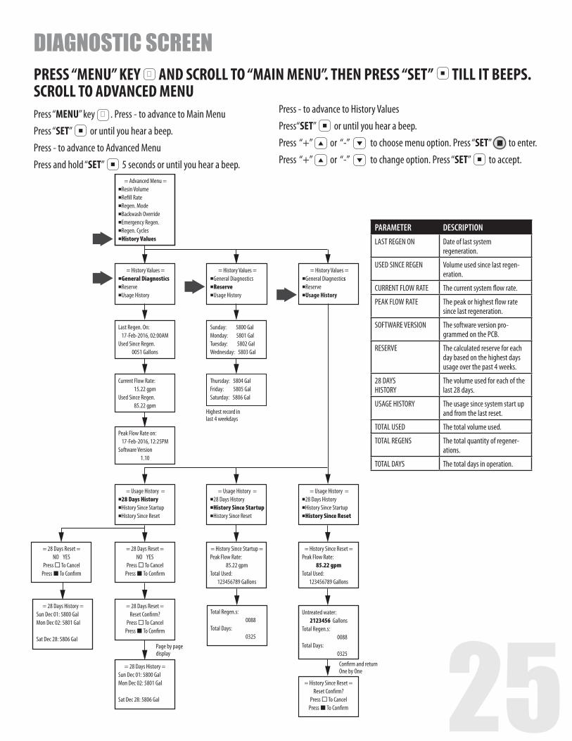
PARAMETER DESCRIPTIONLAST REGEN ON Date of last system
regeneration.
USED SINCE REGEN Volume used since last regen-eration.
CURRENT FLOW RATE The current system flow rate.
PEAK FLOW RATE The peak or highest flow rate since last regeneration.
SOFTWARE VERSION The software version pro-grammed on the PCB.
RESERVE The calculated reserve for each day based on the highest days usage over the past 4 weeks.
28 DAYS HISTORY
The volume used for each of the last 28 days.
USAGE HISTORY The usage since system start up and from the last reset.
TOTAL USED The total volume used.
TOTAL REGENS The total quantity of regener-ations.
TOTAL DAYS The total days in operation.
PRESS “MENU” KEY MENU
SET
AND SCROLL TO “MAIN MENU”. THEN PRESS “SET” MENU
SET TILL IT BEEPS. SCROLL TO ADVANCED MENU
DIAGNOSTIC SCREEN
Press “MENU” key MENU
SET
. Press - to advance to Main Menu
Press “SET” MENU
SET
or until you hear a beep.
Press - to advance to Advanced Menu
Press and hold “SET” MENU
SET
5 seconds or until you hear a beep.
Press - to advance to History Values
Press“SET” MENU
SET
or until you hear a beep.
Press “+” MENU
SET
or “-” MENU
SET to choose menu option. Press “SET” to enter.
Press “+” MENU
SET
or “-” MENU
SET to change option. Press “SET”
MENU
SET
to accept.

Phone Number: 1-888-701-5497 1595 Georgetown Road, Hudson, OH 44236
www.LeafHomeWaterSolutions.com
80155277 2021-04-14