OWNER’S MANUAL - Man Lift Mfg. Co. · Man Lift Mfg. Co. SHU-30 Owner’s Manual 2 INTRODUCTION...
36
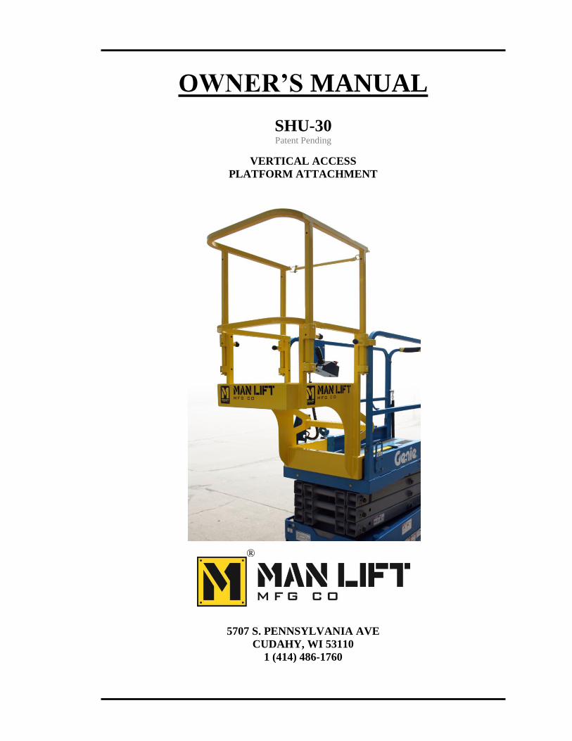
® OWNER’S MANUAL SHU-30 Patent Pending VERTICAL ACCESS PLATFORM ATTACHMENT 5707 S. PENNSYLVANIA AVE CUDAHY, WI 53110 1 (414) 486-1760
Transcript of OWNER’S MANUAL - Man Lift Mfg. Co. · Man Lift Mfg. Co. SHU-30 Owner’s Manual 2 INTRODUCTION...
®
OWNER’S MANUAL
SHU-30 Patent Pending
VERTICAL ACCESS
PLATFORM ATTACHMENT
5707 S. PENNSYLVANIA AVE
CUDAHY, WI 53110
1 (414) 486-1760

Man Lift Mfg. Co.
SHU-30 Owner’s Manual
2
INTRODUCTION
The primary purpose of this manual is to provide the user with a thorough understanding
of the proper operating procedures necessary to comply with the intended use of the
platform attachment.
THIS MANUAL MUST BE RETAINED ON THE UNIT AT ALL TIMES.
Do not attempt to operate the platform attachment and/or the aerial lift with the
platform attachment connected until you have read and understood all information
provided in this manual. A good understanding of the platform attachment cutoff
system, its limitations, and its capabilities will maximize operating efficiency and
safety. The various decals attached to this machine contain vital information. Read
the decals before operating this machine. Proper installation of this platform
attachment is necessary before operation. The instructions in the installation
manual must be followed for proper installation.
It is YOUR RESPONSIBILITY to follow safe procedures while operating on the SHU
platform attachment. The manufacturer of this unit cannot control the wide range of
applications that may be used in carrying out a variety of jobs. Therefore, IT IS THE
USER’S RESPONSIBILITY to consider the safety of all personnel when making
decisions regarding the unit’s intended use.
It is also YOUR RESPONSIBILITY to understand and obey all federal, state, and local
regulations regarding the safe operation and use of aerial work platforms.
MAN LIFT MFG. CO. reserves the right to modify, improve, add, and/or delete certain
design features of its products without any obligation to incorporate new features into
products previously sold. Our manuals are continually updated to reflect these changes.
DO NOT ALTER OR MODIFY THIS UNIT WITHOUT PRIOR WRITTEN
APPROVAL FROM THE MANAGEMENT OF MAN LIFT MFG. CO.
The manufacturer recommends that replacement parts be purchased only through MAN
LIFT MFG. CO. in order to ensure the original integrity of the product. Only trained and
qualified personnel should make repairs and adjustments. Please refer to the Service
section of this manual for information on service and maintenance of the platform
attachment.
If you need assistance or have any service or maintenance questions, Man Lift Mfg.
Co. personnel are always available by phone or fax. The telephone numbers are:
1 (414) 486-1760 Telephone
1 (414) 486-1763 Fax
Serial Number Range G0003-G0102

Man Lift Mfg. Co.
SHU-30 Owner’s Manual
3
TABLE OF CONTENTS
INTRODUCTION……………………………………………………………… 2
WARRANTY..……………………………………………………….………… 4
1. SAFETY …..…………………………………………………..…………… 5
Safety Symbols ………………………………………………………… 5
Safety Rules and Precautions…………………………………………… 6
2. INSTALLATION ……………………………………………..…………… 8
Unloading…….………………………………………………………… 8
Installation Parts………………………………………………………… 8
SHU Platform Attachment Installation Procedure……………………… 9
3. OPERATION…………………………………………………..…………… 16
Start-up Procedure/Shift Change…….…………………..……………… 16
General Operation ……………………………………………………… 16
Platform Attachment Cutoff System………….………………………… 17
Fall Arrest System…….………………………………………………… 17
4. SERVICE….…………………………………………………..…………… 19
Service and Maintenance………………………………..……………… 19
Platform Attachment Cutoff System………….………………………… 20
General Maintenance…………………………………………………… 21
Electrical Schematic..…………………………………………………… 24
5. PARTS….….…………………………………………………..…………… 25
How to Order Parts……………………………………………………… 25
Decals..……………………………………………………..…………… 26
Main Assembly..………………………………………………………… 28
Installation Parts………………………………………………………… 31
Electrical Parts.……………………………………………..…………… 32
SPECIFICATIONS….……………………………………………..…………… 34
LETTER FROM GENIE.…………………………………………..…………… 35

Man Lift Mfg. Co.
SHU-30 Owner’s Manual
4
LIMITED WARRANTY
Man Lift Mfg. Co. warrants to the purchaser that each new SHU vertical access platform
attachment made by Man Lift Mfg. Co. is free from defects in material and/or
workmanship arising under normal use and service for a period of one (1) year after the
original shipment of the platform attachment from the plant of Man Lift Mfg. Co.
Any obligation and liability under this Warranty is expressly limited to repairing or, at
Man Lift Mfg. Co.’s option, replacing free of charge at its factory in Cudahy, WI or at an
authorized repair facility designated by Man Lift Mfg. Co., the defective part. In no
event shall Man Lift Mfg. Co. or its suppliers be liable to the purchaser or any other
person for transportation charges or for any incidental, collateral, special, or
consequential damages, including without limitation damages for loss of profits, loss of
customers, loss of goodwill, or work stoppage, claims by any party other than the
purchaser, or any other similar damage or loss even if Man Lift Mfg. Co., its suppliers, or
its representatives have been advised of the possibility of such damages.
Parts claimed to be defective and for which repair or replacement is desired shall be
returned transportation prepaid to the Man Lift Mfg. Co. factory for inspection. This
Warranty applies to replacement parts provided under the terms of this Warranty only for
the remainder of the Warranty period applicable to the original purchase.
Any operation of the equipment beyond rated capacity, improper use or application of the
platform attachment, substitution upon it of parts not approved by Man Lift Mfg. Co. or
alteration or repair of the platform attachment by any person not authorized by Man Lift
Mfg. Co. shall, at Man Lift Mfg. Co.’s option, void this Warranty. Man Lift Mfg. Co.
shall have no liability or responsibility for damages resulting from any malfunction of
equipment and components not supplied by Man Lift Mfg. Co.
No agent, employee, distributor, dealer, or other representative of Man Lift Mfg. Co. is
authorized to modify this Warranty in any way. Accordingly, additional statements or
presentations by any such representative, whether oral or written, do not constitute
warranties by Man Lift Mfg. Co. and should not be relied upon as limited warranties of
Man Lift Mfg. Co. and no attempt, effort, or promise to repair equipment by Man Lift
Mfg. Co. or any such representative at any time shall modify or extend this Warranty in
any way. If the purchaser has used its own order form, Man Lift Mfg. Co. will honor no
additional or different warranty terms contained in the purchaser’s form. This Warranty
covers only new and unused SHU vertical access platform attachments manufactured by
Man Lift Mfg. Co. Products or parts manufactured by others are covered only by such
warranties as are extended to the purchaser by Man Lift Mfg. Co.’s suppliers.
This Warranty is in lieu of all other warranties, expressed or implied, including but not
limited to warranties of merchantability and fitness for a particular purpose.

Man Lift Mfg. Co.
SHU-30 Owner’s Manual
5
1. SAFETY
SAFETY SYMBOLS
This manual is designed to provide you with the information and instruction to properly
install, operate and maintain your MAN LIFT MFG. CO. SHU-30 platform attachment.
Your failure to read, understand and follow all safety rules, warnings and instructions
will unnecessarily expose you and others to dangerous situations. For your safety and the
safety of those around you, you must operate and maintain your platform attachment as
instructed in this manual.
The MAN LIFT MFG. CO. SHU-30 vertical access platform attachment is designed and
built to provide many years of safe, dependable service. To obtain full benefits from
your SHU-30, always follow the proper operating and maintenance procedures. Only
trained, competent personnel should be allowed to operate or service this unit.
To help you recognize important safety information, we have identified warnings and
instructions that directly impact on safety with the following signals:
“DANGER” INDICATES AN IMMINENTLY HAZARDOUS SITUATION,
WHICH, IF NOT AVOIDED, WILL RESULT IN DEATH OR SERIOUS
INJURY.
“WARNING” Indicates a Potentially Hazardous Situation, Which, if not
Avoided, Could Result in Death or Serious Injury.
“CAUTION” Indicates a Potentially Hazardous Situation, Which, if not
Avoided, May Result In Minor or Moderate Injury.
One final note: The best method to protect yourself and others from injury or death is
to use common sense. If you are unsure of any operation, DO NOT start until you are
satisfied that is safe to proceed.

Man Lift Mfg. Co.
SHU-30 Owner’s Manual
6
SAFETY RULES AND PRECAUTIONS
APPROVED SAFETY HARNESS MUST BE WORN AT ALL TIMES
WHILE OPERATING THE AERIAL LIFT WITH THE SHU VERTICAL
ACCESS PLATFORM ATTACHMENT CONNECTED.
DO NOT EXCEED THE AERIAL LIFT PLATFORM CAPACITY IN ANY
CONFIGURATION.
DO NOT EXCEED THE SHU VERTICAL ACCESS PLATFORM
ATTACHMENT CAPACITY IN ANY CONFIGURATION
DO NOT SIT, STAND OR CLIMB ON THE RAILS OF EITHER THE SHU
VERTICAL ACCESS PLATFORM ATTACHMENT OR AERIAL LIFT
PLATFORM
Please read and understand all safety rules and precautions in the aerial lift
manufacturer’s manual. Unless specified below, all safety rules and
precautions that apply to the aerial lift apply to the lift with the platform
attachment installed.
Modifications of this platform attachment from the original design and
specification without written permission from Man Lift Mfg. Co. is strictly
forbidden. A modification may compromise the safety of the aerial lift, subjecting
users to serious injury or death. Any such modification will void any remaining
warranty.
Read and understand all safety and control information found on the aerial
lift, the platform attachment and in this manual before operating the unit.
Only trained, competent personnel should operate the platform attachment
and aerial lift.
Be aware of all Government and Local rules that may apply to the platform
attachment and its safe operation.

Man Lift Mfg. Co.
SHU-30 Owner’s Manual
7
Approved headgear and other protective equipment must be worn as
required. (In the USA, OSHA approved equipment is required. For other
countries, the appropriate equivalent government body should be consulted).
NEVER fasten safety harness to an adjacent structure while on the work
platform attachment.
DO NOT disable the limit switches.
DO NOT raise, lower or drive the lift while an operator is in the platform
attachment with the rails down
DO NOT operate the lift from inside the platform attachment. If the lift is to
be operated while someone is in the platform attachment, it should be done
by an operator on the aerial lift platform, and only with the platform
attachment rails in the raised and locked position.
Operating this equipment without all safety and control decals in place can
be hazardous.
Complete the “Operational Checklists” found in this manual (see Table of
Contents) at designated intervals.
Complete the maintenance found in the aerial lift manual at designated
intervals.
DO NOT exceed the maximum platform attachment horizontal pull of 100
lbs. (341 kg).
DO NOT use the platform attachment as a crane to lift oversized or hanging
loads.

Man Lift Mfg. Co.
SHU-30 Owner’s Manual
8
2. INSTALLATION
UNLOADING
Remove packaging.
Inspect the unit for damage. Inspect all railings, switches and cables for chafing or road
damage.
Remove all machine tie downs.
Before installing the platform attachment onto the aerial lift, all operators must read and
understand the contents of this Operator’s Manual.
To install the platform attachment onto the aerial lift, please see the Installation Manual for
installation procedure.
INSTALLATION PARTS
PART NUMBER DESCRIPTION QTY
F0137518 SCREW, HHC, 3/8-16 X 2 4
F0137519 SCREW, HHC, 3/8-16 X 2.25 4
F33622 WASHER, LOCK, .375 8
F0137514 SCREW, HHC, 3/8-16 X 1 2
F33082 WASHER, FLAT, SAE, 3/8 4
F37575 NUT, NYLOCK, 3/8-16 2
F31823 SCREW, SELF DRILLING, 1/4-14 X 1 2
10825 CONTROL MOUNT ATTACHMENT 1
10873 DECAL, PLATFORM HEIGHT, SHU 1
10874 DECAL, OVERALL CAPACITY, SHU 1

Man Lift Mfg. Co.
SHU-30 Owner’s Manual
9
FIGURE 1
SHU PLATFORM ATTACHMENT INSTALLATION PROCEDURE
1. Check to make sure that all the components that are needed for
installation are present.
2. At least 2 people are required for proper installation.
3. Remove the extension deck from the aerial lift platform. Please see aerial
lift service manual for instructions on how to remove the platform
extension.
4. Retain roller bracket assemblies from the main deck and the extension
deck. Set aside to be used later. Remove Platform Control Box and
bracket from extension deck (keep mounted to each other) by
disconnecting the 6 pin plug and receptacle at the underside of the aerial
lift platform and unscrewing fasteners or cutting zip ties (whichever is
used).
5. Remove installation parts from platform attachment manual storage box.
Set aside to be used later in the installation process.
6. Transfer all items from aerial lift manual storage box (located on the
extension deck that was removed in Step 2) to the platform attachment
manual storage box.
7. With the railings down and latch bar up, lift the SHU platform
attachment using one person on each side of the platform attachment,
similar to what is shown in Figure 1.
Man Lift Mfg. Co.
SHU-30 Owner’s Manual
10
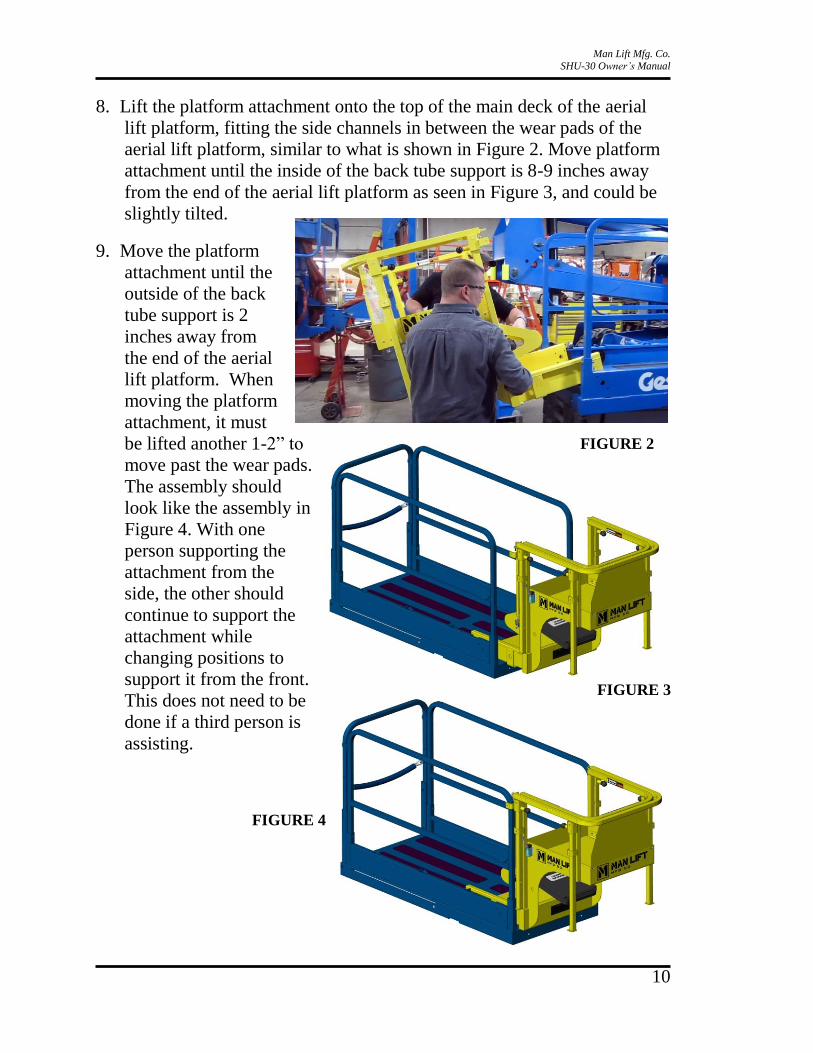
8. Lift the platform attachment onto the top of the main deck of the aerial
lift platform, fitting the side channels in between the wear pads of the
aerial lift platform, similar to what is shown in Figure 2. Move platform
attachment until the inside of the back tube support is 8-9 inches away
from the end of the aerial lift platform as seen in Figure 3, and could be
slightly tilted.
9. Move the platform
attachment until the
outside of the back
tube support is 2
inches away from
the end of the aerial
lift platform. When
moving the platform
attachment, it must
be lifted another 1-2” to
move past the wear pads.
The assembly should
look like the assembly in
Figure 4. With one
person supporting the
attachment from the
side, the other should
continue to support the
attachment while
changing positions to
support it from the front.
This does not need to be
done if a third person is
assisting.
FIGURE 3
FIGURE 4
FIGURE 2
Man Lift Mfg. Co.
SHU-30 Owner’s Manual
11
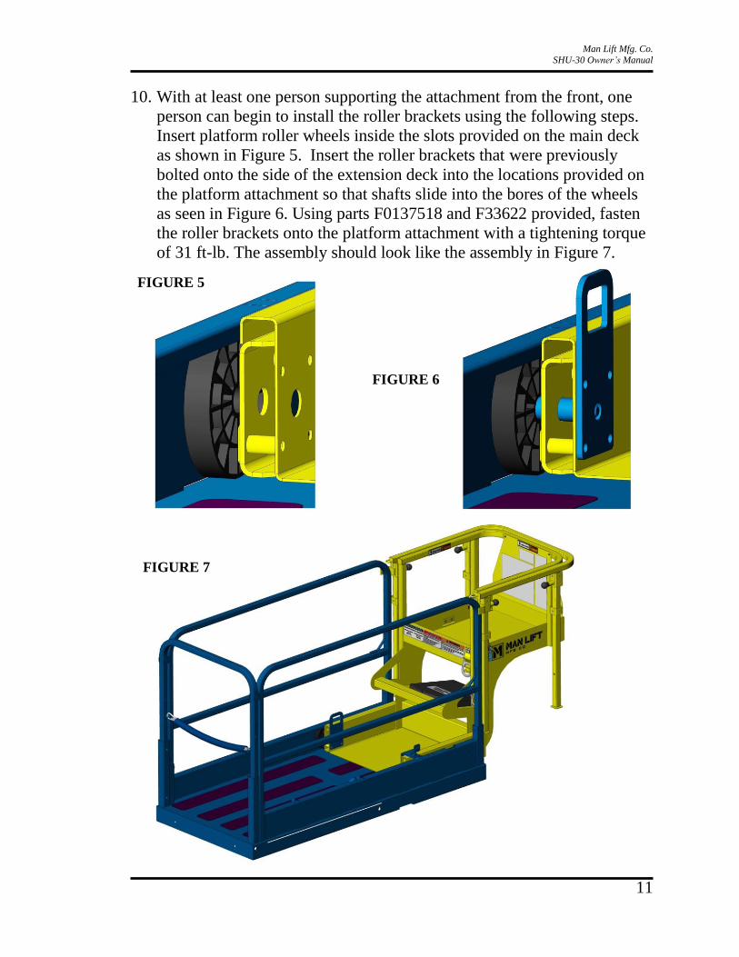
10. With at least one person supporting the attachment from the front, one
person can begin to install the roller brackets using the following steps.
Insert platform roller wheels inside the slots provided on the main deck
as shown in Figure 5. Insert the roller brackets that were previously
bolted onto the side of the extension deck into the locations provided on
the platform attachment so that shafts slide into the bores of the wheels
as seen in Figure 6. Using parts F0137518 and F33622 provided, fasten
the roller brackets onto the platform attachment with a tightening torque
of 31 ft-lb. The assembly should look like the assembly in Figure 7.
FIGURE 5
FIGURE 6
FIGURE 7
Man Lift Mfg. Co.
SHU-30 Owner’s Manual
12
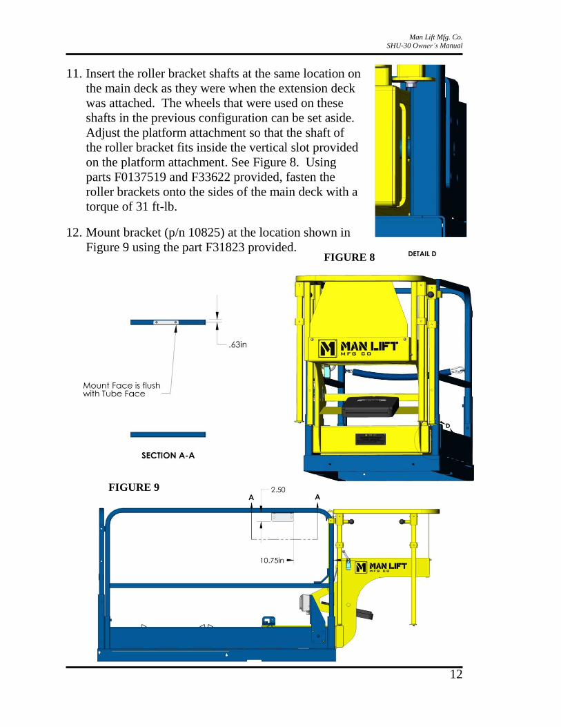
11. Insert the roller bracket shafts at the same location on
the main deck as they were when the extension deck
was attached. The wheels that were used on these
shafts in the previous configuration can be set aside.
Adjust the platform attachment so that the shaft of
the roller bracket fits inside the vertical slot provided
on the platform attachment. See Figure 8. Using
parts F0137519 and F33622 provided, fasten the
roller brackets onto the sides of the main deck with a
torque of 31 ft-lb.
12. Mount bracket (p/n 10825) at the location shown in
Figure 9 using the part F31823 provided.
FIGURE 9
FIGURE 8

Man Lift Mfg. Co.
SHU-30 Owner’s Manual
13
13. Attach the Platform Control Box and bracket to 10825 as shown in
Figure 10 by using the parts F0137514, F33082, and F37575. Run the
end of the cable from the control box into the opening shown in Figure
11.
FIGURE 10
FIGURE 11

Man Lift Mfg. Co.
SHU-30 Owner’s Manual
14
14. Disconnect the two 2-pin connectors that are on the same end of the 3-
way harness. Insert the end of the 2 pin connectors into the slot shown in
Figure 12. Connect the 6 pin receptacle from the platform cable to the
plug on the removed harness and connect the 6 socket plug from the
cable running up on the scissor to the receptacle on the removed harness.
Re-connect the 2 pin connectors to the 3-way receptacle. The wires and
connectors should be mounted as shown in Figure 13.
FIGURE 12
FIGURE 13

Man Lift Mfg. Co.
SHU-30 Owner’s Manual
15
15. Attach decals 10873 and 10874 at the location shown in Figure 14.
16. Perform a shift maintenance inspection before operating.
17. Reverse the process to remove the platform attachment, leaving the
decals on the aerial lift platform.
FIGURE 14

Man Lift Mfg. Co.
SHU-30 Owner’s Manual
16
3. OPERATION
Start-Up Procedures/Shift Checks Before the SHU-30 is put into use each shift, the following checks should be
completed, to ensure that the machine is in good, safe operating condition.
Visually inspect all attachment components for problems such as: missing
parts, torn and disconnected wires.
Check cables for worn areas.
Check functionality of platform attachment cutoff switch system.
Decals and Placards Affixed and Legible
Quick Release Pins Latching Properly
For Service/Maintenance Checklists See Service Manual
GENERAL OPERATION
1. First, in order to operate the platform attachment, ensure that the unit has been
installed correctly and that the switches are working properly (see next section).
2. Attach safety harness to the anchorage point at the back toe board of the attachment
platform.
3. Use the step and the railing to enter the platform.
4. The railing should only be adjusted to two positions: fully raised and fully lowered. In
each position the pins should be fully depressed in the holes of the railing.
There is a pinch point between the sliding rail and the fixed rail when the rail is
completely lowered. Be careful when lowering rails to avoid pinching.
5. The railing shall be in the fully raised position unless the operator cannot access a
certain area.
6. To raise the railings from the lowered position, pull out the pins and turn 90 degrees
to lock. The operator can either
a. Raise the railing and hold it while the first pin is turned and depressed into the
hole then let go of the railing and depress the rest of the pins.
b. Leave one pin unlocked and raise the railing until that pin fully depresses into
the hole in the raised position then depress the rest of the pins.

Man Lift Mfg. Co.
SHU-30 Owner’s Manual
17
PLATFORM ATTACHMENT CUTOFF SYSTEM
The operator must ensure that the platform attachment cutoff system is functioning
properly before operating.
1. The limit switches on the platform attachment are used with the hinged plate to
disable the lift when an operator is inside the platform attachment and the rails are in
the lowered position.
2. When the lift is disabled because of this, the Emergency Stop button must be pushed
in and held for 5 seconds and then pulled back out to reset operation.
FALL ARREST SYSTEM
APPROVED SAFETY HARNESS MUST BE WORN AT ALL TIMES WHILE
OPERATING. THE HARNESS MUST BE CONNECTED TO THE ANCHORAGE
POINT SHOWN BELOW WHILE IN THE PLATFORM ATTACHMENT.
The fall arrest system is used to ensure that the operator on the platform attachment is
safely secured to the platform attachment so that he or she will not fall during normal
operation. The fall arrest system consists of a safety lanyard ring as the anchorage point.
This is located on the back toe board of the platform attachment. See picture below.

Man Lift Mfg. Co.
SHU-30 Owner’s Manual
18
Harnesses must be used with the fall arrest system. The length of the lanyard is 48”.
If an operator does fall when connected to the platform attachment anchorage point, the
weldments and anchorage must be inspected by a qualified Man Lift Manufacturing
Company employee before further use.
THIS FALL ARREST SYSTEM:
o Complies with OSHA 1926.502(d) 1926 Sub-Part M App C
o Is to be used with full body harness and shock absorbing or retractable lanyard
o Max capacity is 250 pounds (with tools)
o Only one person can be connected at a time
o Do not use if visible damage is noted, call 414-486-1760
Man Lift Mfg. Co.
SHU-30 Owner’s Manual
19
4. SERVICE
SERVICE & MAINTENANCE
Many of the parts used in the manufacturing of the SHU-30 platform attachment have
specific properties, and the manufacturer recommends that replacement parts be
purchased only through MAN LIFT MFG. CO. in order to ensure the original integrity of
the product.
Technical Service Bulletins will be forwarded to purchaser when applicable as
determined by Man Lift Mfg. Co.
MAN LIFT MFG. CO.
SERVICE INFORMATION
If you need assistance or have any service or maintenance questions, MAN LIFT
MFG. CO. personnel are always available by phone or fax. The telephone numbers
are:
(414) 988-1234 Telephone
(414) 486-1763 Fax
Man Lift Mfg. Co.
SHU-30 Owner’s Manual
20
PLATFORM ATTACHMENT CUTOFF SYSTEM
The limit switches on the platform attachment are used with the hinged plate to disable
the lift when an operator is inside the platform attachment and the rails are in the lowered
position. The limit switches are wired so that if they are both engaged, the e-stop
actuates. This disables the machine from driving, lifting or lowering. There are two limit
switches. One engages when there is weight in the platform attachment. The other
engages when the sliding rails are moved down. Below are some possible causes for the
system to malfunction.
- Worn Out Rubber Seal
- Obstruction underneath hinged plate
- Limit Switch Misaligned
- Incorrect wiring
- Loose connection(s)
- Cracks or tears
- Eroded Connection
- Hinged Plate distorted or flexing abnormally
Man Lift Mfg. Co.
SHU-30 Owner’s Manual
21
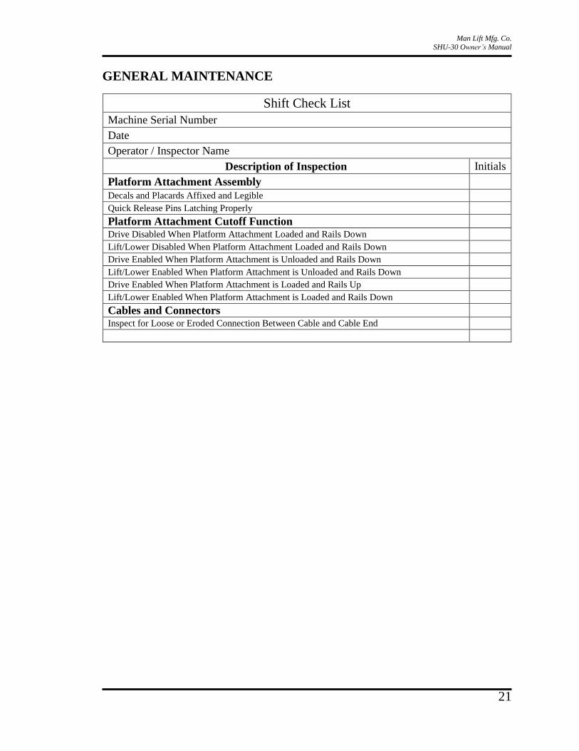
GENERAL MAINTENANCE
Shift Check List
Machine Serial Number
Date
Operator / Inspector Name
Description of Inspection Initials
Platform Attachment Assembly
Decals and Placards Affixed and Legible
Quick Release Pins Latching Properly
Platform Attachment Cutoff Function
Drive Disabled When Platform Attachment Loaded and Rails Down
Lift/Lower Disabled When Platform Attachment Loaded and Rails Down
Drive Enabled When Platform Attachment is Unloaded and Rails Down
Lift/Lower Enabled When Platform Attachment is Unloaded and Rails Down
Drive Enabled When Platform Attachment is Loaded and Rails Up
Lift/Lower Enabled When Platform Attachment is Loaded and Rails Down
Cables and Connectors
Inspect for Loose or Eroded Connection Between Cable and Cable End

Man Lift Mfg. Co.
SHU-30 Owner’s Manual
22
Weekly Check List
Machine Serial Number
Date
Operator / Inspector Name
Description of Inspection Initials
Platform Attachment Assembly
Check Handrails for Secure Installation
All Plastic Buttons/Slider Pads In Place
Clean Out Area Underneath Hinged Floor Plate
Serial Plates Affixed and Legible
Folding Bar Latching Properly
Cables and Connectors
Verify that the Connections are Tight
General
Operators Manual Inside Storage Box

Man Lift Mfg. Co.
SHU-30 Owner’s Manual
23
Annual Check List
Machine Serial Number
Date
Operator / Inspector Name
Description of Inspection Initials
Platform Attachment Assembly
Check Handrails for Secure Installation
Decals and Placards Affixed and Legible
All Plastic Buttons/Slider Pads In Place
Clean Out Area Underneath Hinged Floor Plate
Serial Plates Affixed and Legible
Folding Bar Latching Properly
Inspect Rubber Seals and Replace if Not Compressing Properly
Platform Attachment Cutoff Function
Drive Disabled When Platform Attachment Loaded and Rails Down
Lift/Lower Disabled When Platform Attachment Loaded and Rails Down
Drive Enabled When Platform Attachment is Unloaded and Rails Down
Lift/Lower Enabled When Platform Attachment is Unloaded and Rails Down
Drive Enabled When Platform Attachment is Loaded and Rails Up
Lift/Lower Enabled When Platform Attachment is Loaded and Rails Down
Cables and Connectors
Inspect for Cracks, Tears, or Other Damage
Verify that the Connections are Tight
Inspect for Loose or Eroded Connection Between Cable and Cable End
Verify That Cables Stay Connected When Lift is at Maximum Height
General
Operators Manual Inside Storage Box

Man Lift Mfg. Co.
SHU-30 Owner’s Manual
24
SHU-30 ELECTRICAL SCHEMATIC

Man Lift Mfg. Co.
SHU-30 Owner’s Manual
25
5. PARTS
HOW TO ORDER PARTS
1. When ordering parts for your SHU-30 vertical access platform attachment, ensure that
you are able to give the model and serial number(s) of all units for which parts are
needed. The serial numbers will assist the Man Lift Parts Department in providing the
correct parts.
2. If known, please specify the Man Lift part number(s) for the part(s) you require, and
always provide a complete description of all parts.
3. Fax orders are preferable, though parts may be ordered by mail, e-mail and telephone.
4. Parts needed for warranty repair must be purchased through Man Lift Parts Department.
5. Man Lift classifies its orders in the following ways:
Emergency: Top priority. All efforts are made to ship the order the day the order is
received; when possible, parts must be pulled off the assembly line.
Standard: Order to be shipped within a 48-hour period.
Stock: Order to be shipped within 2 weeks.
6. Man Lift has a $25.00 Net Minimum billing charge per order.
7. All price quotations are valid for 90 days.
8. Parts shown as shipped on the Man Lift packing list and subsequent invoice but not
received by the dealer/customer MUST be reported within 10 days after the date
shipment. If the parts are still required, a NEW parts order must be submitted. Shortages
and discrepancies will be reviewed on an individual basis by the Parts staff and
adjustments will be made accordingly.
Invoice discrepancies regarding incorrect prices or discounts should be reported
immediately to the Parts Department. Report the Sales Order Number and invoice
number. Your request will be reviewed and adjustments will be made accordingly.
Man Lift Mfg. Co.
SHU-30 Owner’s Manual
26
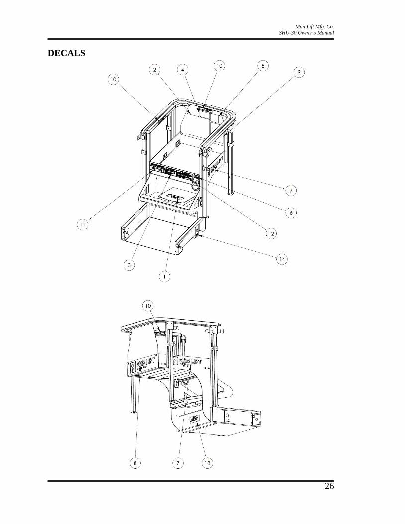
DECALS
Man Lift Mfg. Co.
SHU-30 Owner’s Manual
27
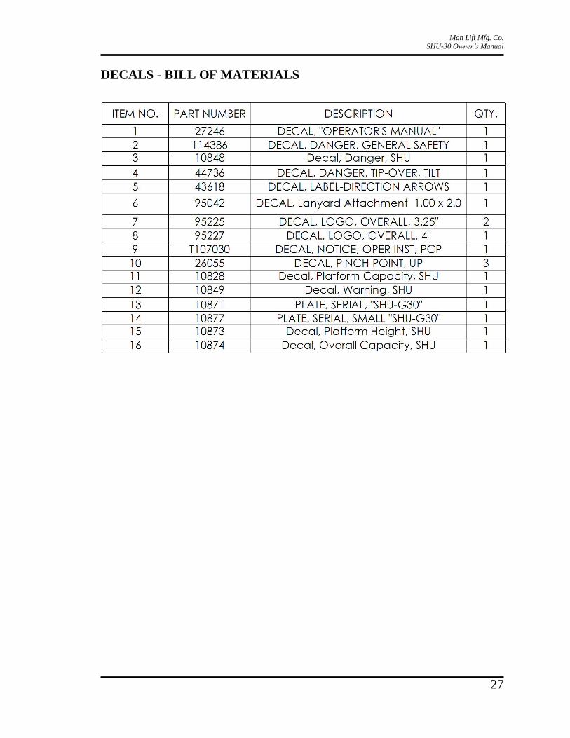
DECALS - BILL OF MATERIALS
Man Lift Mfg. Co.
SHU-30 Owner’s Manual
28
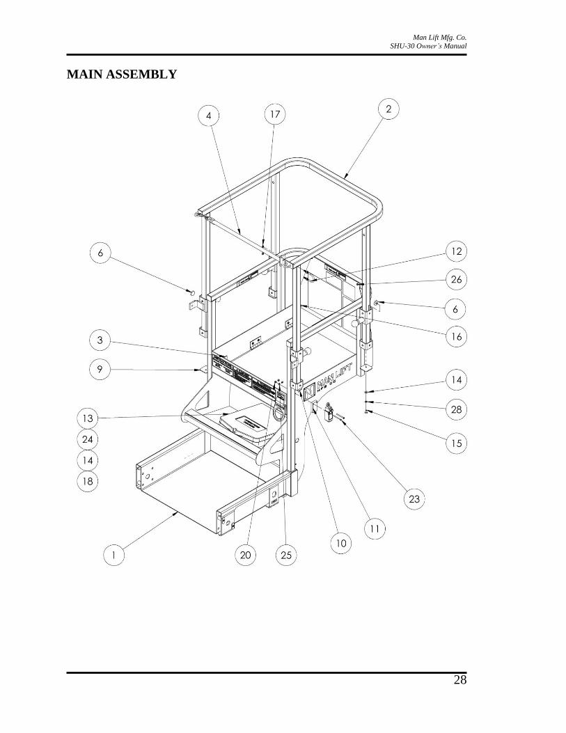
MAIN ASSEMBLY
Man Lift Mfg. Co.
SHU-30 Owner’s Manual
29
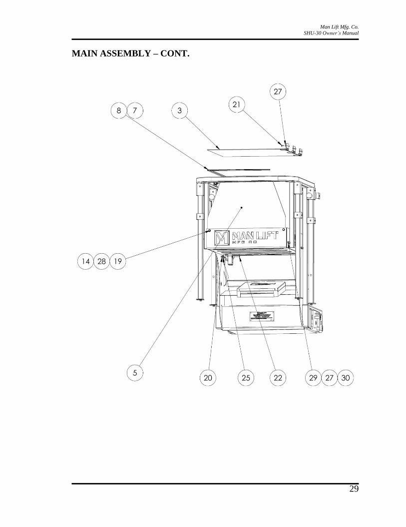
MAIN ASSEMBLY – CONT.

Man Lift Mfg. Co.
SHU-30 Owner’s Manual
30
MAIN ASSEMBLY – BILL OF MATERIALS

Man Lift Mfg. Co.
SHU-30 Owner’s Manual
31
INSTALLATION PARTS

Man Lift Mfg. Co.
SHU-30 Owner’s Manual
32
ELECTRICAL
6
7 8, 9 10 8, 9
3
4
3
5
1
2
8, 11

Man Lift Mfg. Co.
SHU-30 Owner’s Manual
33
ELECTRICAL – BILL OF MATERIALS
Man Lift Mfg. Co.
SHU-30 Owner’s Manual
34
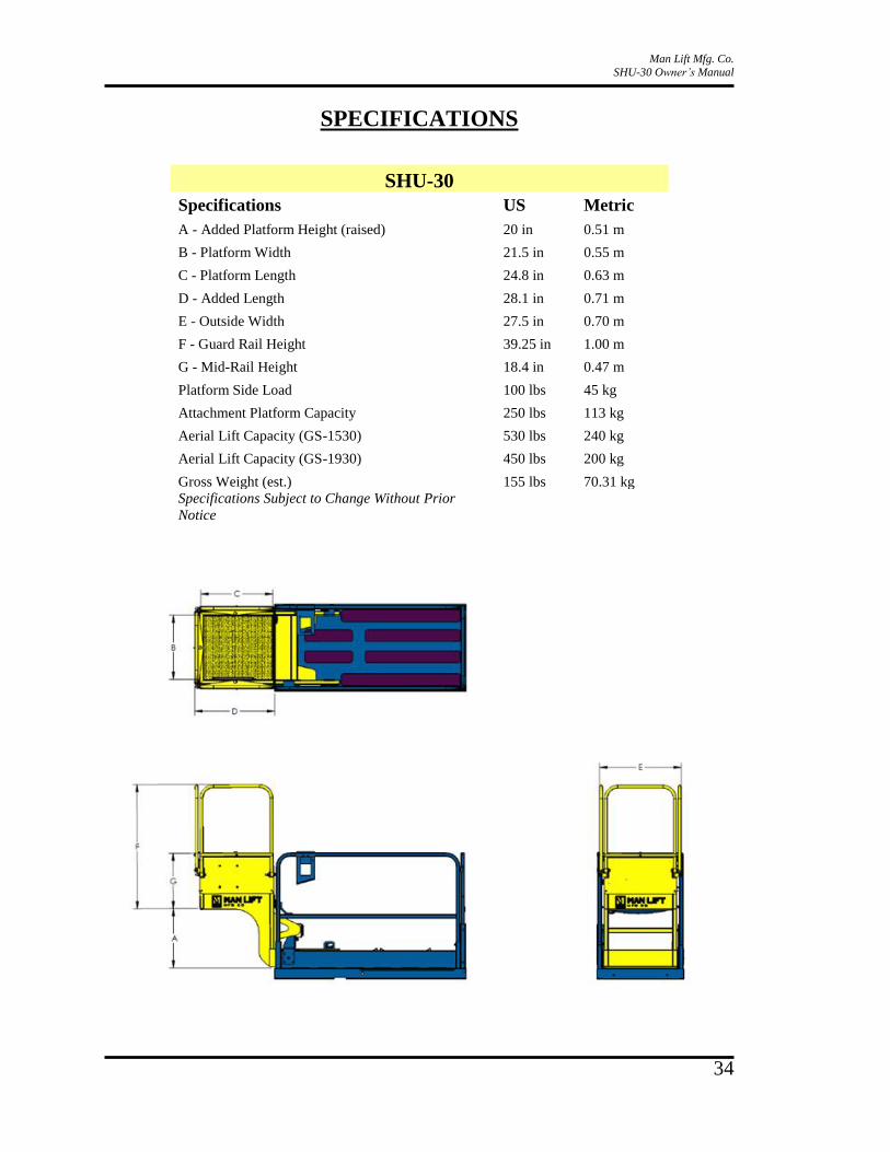
SPECIFICATIONS
SHU-30
Specifications US Metric
A - Added Platform Height (raised) 20 in 0.51 m
B - Platform Width 21.5 in 0.55 m
C - Platform Length 24.8 in 0.63 m
D - Added Length 28.1 in 0.71 m
E - Outside Width 27.5 in 0.70 m
F - Guard Rail Height 39.25 in 1.00 m
G - Mid-Rail Height 18.4 in 0.47 m
Platform Side Load 100 lbs 45 kg
Attachment Platform Capacity 250 lbs 113 kg
Aerial Lift Capacity (GS-1530) 530 lbs 240 kg
Aerial Lift Capacity (GS-1930) 450 lbs 200 kg
Gross Weight (est.) 155 lbs 70.31 kg
Specifications Subject to Change Without Prior
Notice

18340 NE 76th Street • Redmond, WA 98052 • USA • Phone: 800-536 1800 • 425-556-1800
1 of 2
August 16, 2013
Subject: Attachment of the Man Lift Manufacturing SHU Platform. Subject to the terms and conditions of this letter, Genie Industries Inc. approves the use of Genie Scissors when modified in accordance with Man Lift Manufacturing (MLM) requirements for installation and use of the SHU platform. The machine with the SHU attachment must be used in accordance with the instructions in the Genie Scissor Operator’s Manual and MLM SHU Manual.
Warning: Failure to comply with all restrictions, instructions and warnings contained in this letter, the Genie Scissor Lift Operators Manual, the Man Lift SHU Operator’s manual(s) and decals and the applicable installation, safety or owner’s manual could result in death or serious injury. Application Description: This applies only to SHU – vertical access platform attachment, a device manufactured by Man Lift Manufacturing and is only applicable to the Genie models listed on the installation instructions provided by Man Lift Manufacturing. Owner/Employer/User/Operator Requirements: 1) No modification to the Genie equipment, or use of it outside the proposed application, is
permitted outside the approval criteria contained hereinafter. 2) A copy of this letter must accompany the operators manual at all times in the weather resistant
storage compartment located on the equipment at the job-site where this modification/application is approved and authorized by the user/employer.
3) Operators must be trained and qualified how to safely operate the modified equipment, or use it in the proposed application, and be familiar with the specific model of Genie equipment as follows: a) Be familiar, and comply, with the equipment operating and safety manuals. b) Understand all control functions, decals and warnings. c) Be aware of and understand all safety devices specific to the equipment being used. d) Be instructed regarding the specific hazards associated with using the Genie equipment, in
its modified state, or in the proposed application, and utilize all means, including those provided by the user/employer, to avoid them.
4) The user/employer and the operator shall comply with all applicable jobsite, local, state, provincial, or federal rules, regulations, and standards related to the use of the equipment and its modification.
5) The Genie equipment must be in proper working condition and configuration. Additional Requirements: Installation and use of the SHU must comply with requirements provided by Man Lift Manufacturing.
18340 NE 76th Street • Redmond, WA 98052 • USA • Phone: 800-536 1800 • 425-556-1800
2 of 2
In consideration for Genie’s authorization herein, the equipment owner hereby agrees to indemnify and hold harmless Genie Industries Inc. and its parent and affiliated companies against any and all liability, claims, suits, losses, costs and legal fees caused by, arising out of, or resulting from the approved modification/application of the Genie equipment; any negligent act in the operation of the equipment by the owner, user and/or operator; the failure to comply with the criteria set forth in this letter related to the modification/application; the design, manufacture and installation of any modification; the safety rules and operating instructions in the Operator's Manual; the design and placement of any safety decals; the operation of the equipment by the owner, user and/or operator; and any negligent act or omission related to the equipment, its use or its modification. BY PROCEEDING WITH THE MODIFICATION/APPLICATION AUTHORIZED HEREIN, YOU AGREE TO THE CONTENTS OF THIS LETTER AND ITS CONDITIONS. IF YOU DO NOT AGREE, DO NOT PROCEED WITH THE PROPOSED MODIFICATION/APPLICATION.