Owners manual for 2007 JEEP Wrangler - Courtesy of TheJeepStore
467
TABLE OF CONTENTS SECTION PAGE 1 INTRODUCTION ............................................................. 3 2 THINGS TO KNOW BEFORE STARTING YOUR VEHICLE ............................. 11 3 UNDERSTANDING THE FEATURES OF YOUR VEHICLE .............................. 81 4 UNDERSTANDING YOUR INSTRUMENT PANEL ................................... 197 5 STARTING AND OPERATING ................................................. 261 6 WHAT TO DO IN EMERGENCIES .............................................. 349 7 MAINTAINING YOUR VEHICLE ............................................... 361 8 MAINTENANCE SCHEDULES .................................................. 415 9 IF YOU NEED CONSUMER ASSISTANCE ......................................... 439 10 INDEX .................................................................... 449 1 2 3 4 5 6 7 8 9 10
-
Upload
seaviewjeep1 -
Category
Automotive
-
view
340 -
download
2
description
Owners manual for 2007 JEEP Wrangler www.thejeepstore.com-JEEP Dealer in NJ SECTION TABLE OF CONTENTS PAGE 1 INTRODUCTION 2 THINGS TO KNOW BEFORE STARTING YOUR VEHICLE 3 UNDERSTANDING THE FEATURES OF YOUR VEHICLE 4 UNDERSTANDING YOUR INSTRUMENT PANEL . . . . . . 5 STARTING AND OPERATING . . . . . . . . . . . . . . . . . . . 6 WHAT TO DO IN EMERGENCIES . . . . . . . . . . . . . . . . 7 MAINTAINING YOUR VEHICLE . . . . . . . . . . . . . . . . . . 8 MAINTENANCE SCHEDULES . . . . . . . . . . . . . . . . . . . 9 IF YOU NEED CONSUMER ASSISTANCE . . . . . . . . . .
Transcript of Owners manual for 2007 JEEP Wrangler - Courtesy of TheJeepStore
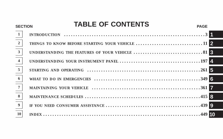
TABLE OF CONTENTSSECTION PAGE
1 INTRODUCTION . . . . . . . . . . . . . . . . . . . . . . . . . . . . . . . . . . . . . . . . . . . . . . . . . . . . . . . . . . . . . 3
2 THINGS TO KNOW BEFORE STARTING YOUR VEHICLE . . . . . . . . . . . . . . . . . . . . . . . . . . . . . 11
3 UNDERSTANDING THE FEATURES OF YOUR VEHICLE . . . . . . . . . . . . . . . . . . . . . . . . . . . . . . 81
4 UNDERSTANDING YOUR INSTRUMENT PANEL . . . . . . . . . . . . . . . . . . . . . . . . . . . . . . . . . . . 197
5 STARTING AND OPERATING . . . . . . . . . . . . . . . . . . . . . . . . . . . . . . . . . . . . . . . . . . . . . . . . . 261
6 WHAT TO DO IN EMERGENCIES . . . . . . . . . . . . . . . . . . . . . . . . . . . . . . . . . . . . . . . . . . . . . . 349
7 MAINTAINING YOUR VEHICLE . . . . . . . . . . . . . . . . . . . . . . . . . . . . . . . . . . . . . . . . . . . . . . . 361
8 MAINTENANCE SCHEDULES . . . . . . . . . . . . . . . . . . . . . . . . . . . . . . . . . . . . . . . . . . . . . . . . . . 415
9 IF YOU NEED CONSUMER ASSISTANCE . . . . . . . . . . . . . . . . . . . . . . . . . . . . . . . . . . . . . . . . . 439
10 INDEX . . . . . . . . . . . . . . . . . . . . . . . . . . . . . . . . . . . . . . . . . . . . . . . . . . . . . . . . . . . . . . . . . . . . 449
1
2
3
4
5
6
7
8
9
10

INTRODUCTION
CONTENTS
� Introduction . . . . . . . . . . . . . . . . . . . . . . . . . . . 4
▫ Roll Over Warning . . . . . . . . . . . . . . . . . . . . . 5
� How To Use This Manual . . . . . . . . . . . . . . . . . . 7
� Warnings And Cautions . . . . . . . . . . . . . . . . . . . 9
� Vehicle Identification Number . . . . . . . . . . . . . . . 9
� Vehicle Modifications/Alterations . . . . . . . . . . . . 9
1
INTRODUCTIONThis is a specialized utility vehicle designed for bothon-road and off-road use. It can go places and performtasks for which conventional two-wheel drive enclosedvehicles were not intended. It handles and maneuversdifferently from many passenger cars both on-road andoff-road, so take time to become familiar with yourvehicle.
Before you start to drive this vehicle, read the Owner’sManual. Be sure you are familiar with all vehicle controls,particularly those used for braking, steering, transmis-sion, and transfer case shifting. Learn how your vehiclehandles on different road surfaces. Your driving skillswill improve with experience. When driving off-road orworking the vehicle, don’t overload the vehicle or expectthe vehicle to overcome the natural laws of physics.Always observe federal, state, provincial and local lawswherever you drive.
As with other vehicles of this type, failure to operate thisvehicle correctly may result in loss of control or anaccident. Be sure to read “On-Road/Off-Road DrivingTips” in this manual.
WARNING!
Never leave children alone in a vehicle. Leavingchildren in a vehicle unattended is dangerous for anumber of reasons. A child or others could be seri-ously or fatally injured. Do not leave the keys in theignition. A child could operate power windows,other controls, or move the vehicle.
4 INTRODUCTION
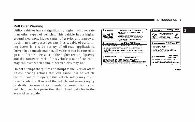
Roll Over WarningUtility vehicles have a significantly higher roll over ratethan other types of vehicles. This vehicle has a higherground clearance, higher center of gravity, and narrowertrack than many passenger cars. It is capable of perform-ing better in a wide variety of off-road applications.Driven in an unsafe manner, all vehicles can be caused togo out of control. Because of the higher center of gravityand the narrower track, if this vehicle is out of control itmay roll over when some other vehicles may not.
Do not attempt sharp turns or abrupt maneuvers or otherunsafe driving actions that can cause loss of vehiclecontrol. Failure to operate this vehicle safely may resultin an accident, roll over of the vehicle and serious injuryor death. Because of its open-body construction, yourvehicle offers less protection than closed vehicles in theevent of an accident.
INTRODUCTION 5
1
Failure to use driver and passenger seat belts providedis a major cause of severe or fatal injury. In fact, the U.S.government notes that the universal use of existing seatbelts could cut the highway death toll by 10,000 or moreeach year, and could reduce disabling injuries by 2million annually. In a roll over crash, an unbelted personis significantly more likely to die than a person wearinga seal belt. Always buckle up.
Although your vehicle may be equipped with a soft topor optional hard top to give the occupants protectionfrom the weather, these tops do not offer structuralprotection in the event of an accident and do not changethe open-body characteristic of the vehicle. Even thoughyour vehicle has a sport bar and side bars for some extraprotection, it is a truly open vehicle-there is no structuralintegrated top and it has low sides and a folding wind-shield. Many of these vehicles do not have fully enclosedhard doors.
Operating this vehicle at excessive speeds or whileintoxicated may result in loss of control, collision withother vehicles or objects, going off the road, or overturn-ing, any of which may lead to serious injury or death.Also, failure to use standard seat belts subjects thedriver and passengers to a greater risk of being thrownout of an open-body vehicle than out of a closed vehiclein an accident which can result in injury or death.
This manual has been prepared with the assistance ofservice and engineering specialists to acquaint you withthe operation and maintenance of your new vehicle. It issupplemented by a Warranty Information Booklet andvarious customer oriented documents. You are urged toread these publications carefully. Following the instruc-tions and recommendations in this manual will helpassure safe and enjoyable operation of your vehicle.
6 INTRODUCTION
NOTE: After you read the manual, it should be storedin the vehicle for convenient reference and remain withthe vehicle when sold so that the new owner will beaware of all safety warnings.
When it comes to service, remember that your authorizeddealer knows your vehicle best, has the factory-trainedtechnicians and genuine Mopar� parts, and is interestedin your satisfaction.
HOW TO USE THIS MANUALConsult the table of contents to determine which sectioncontains the information you desire.
The detailed index, at the rear of this manual, contains acomplete listing of all subjects.
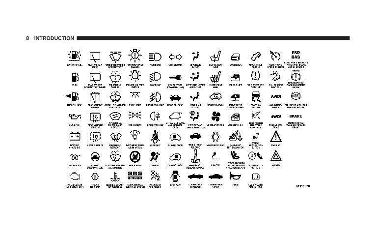
Consult the following table for a description of thesymbols that may be used on your vehicle or throughoutthis owner manual:
INTRODUCTION 7
1
8 INTRODUCTION
WARNINGS AND CAUTIONSThis manual contains WARNINGS against operatingprocedures, which could result in an accident or bodilyinjury. It also contains CAUTIONS against procedures,which could result in damage to your vehicle. If you donot read this entire manual, you may miss importantinformation. Observe all Warnings and Cautions.
VEHICLE IDENTIFICATION NUMBERThe vehicle identification number (VIN) is found on astamped plate located on the left front corner of theinstrument panel pad, visible from outside of vehiclethrough windshield. This number also appears on theAutomobile Information Disclosure Label affixed to awindow on your vehicle. Save this label for a convenientrecord of your vehicle identification number and optionalequipment.
NOTE: It is illegal to remove the VIN plate.
VEHICLE MODIFICATIONS/ALTERATIONS
WARNING!
Any modifications or alterations to this vehicle couldseriously affect its roadworthiness and safety andmay lead to an accident resulting in serious injury ordeath.
INTRODUCTION 9
1

THINGS TO KNOW BEFORE STARTING YOUR VEHICLE
CONTENTS
� A Word About Your Keys . . . . . . . . . . . . . . . . . .14
▫ Ignition Key Removal . . . . . . . . . . . . . . . . . . .14
▫ Key-In-Ignition Reminder . . . . . . . . . . . . . . . .15
� Steering Wheel Lock — If Equipped . . . . . . . . . .15
▫ To Manually Lock The Steering Wheel . . . . . . .15
▫ To Release The Steering Wheel Lock . . . . . . . . .16
� Sentry Key Immobilizer System . . . . . . . . . . . . . .16
▫ Important Note About Service . . . . . . . . . . . . .17
▫ Replacement Keys . . . . . . . . . . . . . . . . . . . . . .17
▫ Customer Key Programming . . . . . . . . . . . . . .18
▫ General Information . . . . . . . . . . . . . . . . . . . .18
� Security Alarm System — If Equipped . . . . . . . . .19
▫ To Set The Alarm . . . . . . . . . . . . . . . . . . . . . .19
▫ To Disarm The System . . . . . . . . . . . . . . . . . . .19
� Illuminated Entry . . . . . . . . . . . . . . . . . . . . . . . .20
� Remote Keyless Entry — If Equipped . . . . . . . . .20
▫ To Unlock The Doors And Swing Gate . . . . . . .21
▫ To Lock The Doors And Swing Gate . . . . . . . . .21
2
▫ Using The Panic Alarm . . . . . . . . . . . . . . . . . .22
▫ To Turn Off “Flash Lights With Lock” . . . . . . . .22
▫ Programming Additional Transmitters . . . . . . . .23
▫ General Information . . . . . . . . . . . . . . . . . . . .24
▫ Battery Replacement . . . . . . . . . . . . . . . . . . . .25
� Doors . . . . . . . . . . . . . . . . . . . . . . . . . . . . . . . .26
▫ Front Door Removal . . . . . . . . . . . . . . . . . . . .26
▫ Rear Door Removal (4 Door Models) . . . . . . . .27
� Door Locks . . . . . . . . . . . . . . . . . . . . . . . . . . . .29
▫ Manual Door Locks . . . . . . . . . . . . . . . . . . . . .30
▫ Power Door Locks — If Equipped . . . . . . . . . .31
� Windows . . . . . . . . . . . . . . . . . . . . . . . . . . . . .32
▫ Power Windows — If Equipped . . . . . . . . . . . .32
▫ Wind Buffeting . . . . . . . . . . . . . . . . . . . . . . . .34
� Rear Swing Gate . . . . . . . . . . . . . . . . . . . . . . . .34
� Occupant Restraints . . . . . . . . . . . . . . . . . . . . . .36
▫ Lap/Shoulder Belts . . . . . . . . . . . . . . . . . . . . .37
▫ Rear Center Lap/Shoulder Belt RetractorLock-Out . . . . . . . . . . . . . . . . . . . . . . . . . . . .42
▫ Adjustable Upper Shoulder Belt Anchorage . . . .43
▫ Seat Belt Pretensioners . . . . . . . . . . . . . . . . . . .44
▫ Enhanced Seat Belt Use Reminder System(BeltAlert) . . . . . . . . . . . . . . . . . . . . . . . . . . .45
▫ Seat Belts And Pregnant Women . . . . . . . . . . . .46
▫ Seat Belt Extender . . . . . . . . . . . . . . . . . . . . . .46
▫ Driver And Front Passenger SupplementalRestraint Systems (SRS) . . . . . . . . . . . . . . . . . .47
12 THINGS TO KNOW BEFORE STARTING YOUR VEHICLE
▫ Child Restraint . . . . . . . . . . . . . . . . . . . . . . . .64
� Engine Break-In Recommendations . . . . . . . . . . .77
� Safety Tips . . . . . . . . . . . . . . . . . . . . . . . . . . . .78
▫ Exhaust Gas . . . . . . . . . . . . . . . . . . . . . . . . . .78
▫ Safety Checks You Should Make Inside TheVehicle . . . . . . . . . . . . . . . . . . . . . . . . . . . . . .79
▫ Safety Checks You Should Make Outside TheVehicle . . . . . . . . . . . . . . . . . . . . . . . . . . . . . .80
THINGS TO KNOW BEFORE STARTING YOUR VEHICLE 13
2
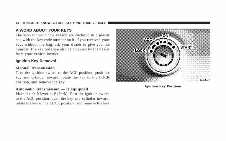
A WORD ABOUT YOUR KEYSThe keys for your new vehicle are enclosed in a plasticbag with the key code number on it. If you received yourkeys without the bag, ask your dealer to give you thenumber. The key code can also be obtained by the dealerfrom your vehicle invoice.
Ignition Key Removal
Manual TransmissionTurn the ignition switch to the ACC position, push thekey and cylinder inward, rotate the key to the LOCKposition, and remove the key.
Automatic Transmission — If EquippedPlace the shift lever in P (Park). Turn the ignition switchto the ACC position, push the key and cylinder inward,rotate the key to the LOCK position, and remove the key.
Ignition Key Positions
14 THINGS TO KNOW BEFORE STARTING YOUR VEHICLE
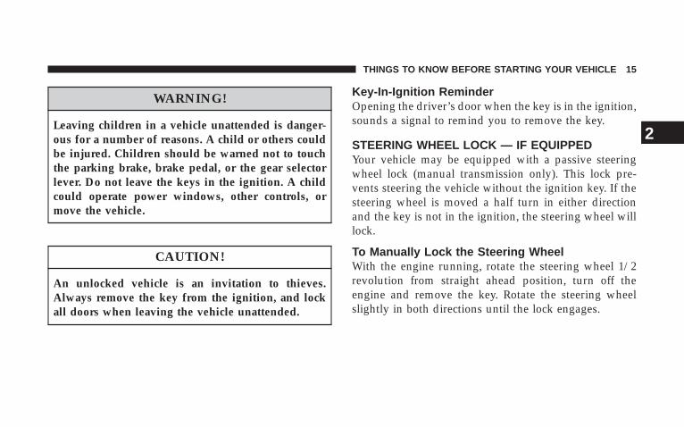
WARNING!
Leaving children in a vehicle unattended is danger-ous for a number of reasons. A child or others couldbe injured. Children should be warned not to touchthe parking brake, brake pedal, or the gear selectorlever. Do not leave the keys in the ignition. A childcould operate power windows, other controls, ormove the vehicle.
CAUTION!
An unlocked vehicle is an invitation to thieves.Always remove the key from the ignition, and lockall doors when leaving the vehicle unattended.
Key-In-Ignition ReminderOpening the driver’s door when the key is in the ignition,sounds a signal to remind you to remove the key.
STEERING WHEEL LOCK — IF EQUIPPEDYour vehicle may be equipped with a passive steeringwheel lock (manual transmission only). This lock pre-vents steering the vehicle without the ignition key. If thesteering wheel is moved a half turn in either directionand the key is not in the ignition, the steering wheel willlock.
To Manually Lock the Steering WheelWith the engine running, rotate the steering wheel 1/2revolution from straight ahead position, turn off theengine and remove the key. Rotate the steering wheelslightly in both directions until the lock engages.
THINGS TO KNOW BEFORE STARTING YOUR VEHICLE 15
2
To Release the Steering Wheel LockInsert the key in the ignition and turn the wheel slightlyto the right or left to disengage the lock.
NOTE: If you turned the wheel to the right to engagethe lock, you must turn the wheel slightly to the right todisengage it. If you turned the wheel to the left to engagethe lock, turn the wheel slightly to the left to disengage it.
SENTRY KEY IMMOBILIZER SYSTEMThe Sentry Key Immobilizer System (SKIM) preventsunauthorized operation of the vehicle by disabling theengine. The system will shut the engine down after 2seconds of running if an invalid key is used to start thevehicle. This system utilizes ignition keys which have anelectronic chip (transponder) embedded into them. Onlykeys that have been programmed to the vehicle can beused to start and operate the vehicle for longer than the2 second validation time period.
The Sentry Key Immobilizer System does not need to bearmed or activated. Operation of the system is automaticregardless of whether or not the vehicle is locked orunlocked. During normal operation, the “Security AlarmSystem Indicator Light” will come on for 3 secondsimmediately after the ignition switch is turned on for abulb check. Afterwards, if the bulb remains on, thisindicates a malfunction in the electronics. If the bulbbegins to flash immediately after the ignition switch isturned on, this indicates that an invalid key is being usedto start the vehicle. Both of these conditions will result inthe engine being shut down after 2 seconds of running.Keep in mind that a key which has not been programmedis also considered an invalid key even if it is cut to fit theignition for that vehicle.
If the “Security Alarm System Indicator Light” comes onduring normal vehicle operation (it has been running for
16 THINGS TO KNOW BEFORE STARTING YOUR VEHICLE
longer than 10 seconds) a fault has been detected in theelectronics and the vehicle should be serviced as soon aspossible.
NOTE:• The Sentry Key Immobilizer System is not compatible
with remote starting systems. Use of these systemsmay result in vehicle starting problems and loss ofsecurity protection.
• Mobil Speedpass™, additional Sentry Keys, or anyother transponder equipped components on the samekeychain will not cause a key-related (Transponder)fault unless the additional part is physically heldagainst the ignition key being used when starting thevehicle. Also, cell phones, pagers, or other RF electron-ics will not cause interference with this system.
All of the keys provided with your new vehicle havebeen programmed to the vehicle electronics.
Important Note About ServiceA four digit PIN number is needed to service the SentryKey Immobilizer System. This number can be obtainedfrom your authorized dealer. However, this number canalso be found on your customer invoice that you weregiven upon receipt of your vehicle.
Replacement Keys
NOTE: Only keys that have been programmed to thevehicle electronics can be used to start the vehicle. Oncea Sentry Key has been programmed to a vehicle, it cannotbe programmed to any other vehicle.
At the time of purchase, the original owner is providedwith a four digit PIN number. This number is requiredfor dealer replacement of keys. Duplication of keys maybe performed at an authorized dealer or by using theCustomer Key Programming procedure. This procedure
THINGS TO KNOW BEFORE STARTING YOUR VEHICLE 17
2
consists of programming a blank key to the vehicleelectronics. A blank key is one which has never beenprogrammed.
NOTE: When having the Sentry Key System serviced,bring all vehicle keys to the dealer.
Customer Key Programming
You can program new keys to the system if you have twovalid keys by doing the following:
1. Cut the additional Sentry Key Transponder blank(s) tomatch the ignition switch lock cylinder key code.
2. Insert the first valid key into the ignition switch andturn the ignition switch ON for at least 3 seconds but nolonger than 15 seconds. Turn the ignition switch OFF andremove the first key.
3. Insert the second valid key and turn the ignitionswitch ON within 15 seconds. After ten seconds, a chime
will sound and the “Security Alarm System IndicatorLight” will begin to flash. Turn the ignition switch OFFand remove the second key.
4. Insert a blank Sentry Key into the ignition switch andturn the ignition switch ON within 60 seconds. After 10seconds, a single chime will sound. The “Security AlarmSystem Indicator Light” will stop flashing, turn on for 3seconds; then turn off.
The new Sentry Key has been programmed. Repeat thisprocess to program up to a total of 8 keys.
General InformationThe Sentry Key Immobilizer System complies with FCCrules part 15 and with RSS-210 of Industry Canada.Operation is subject to the following two conditions:
1. This device may not cause harmful interference.
18 THINGS TO KNOW BEFORE STARTING YOUR VEHICLE
2. This device must accept any interference that may bereceived, including interference that may cause undes-ired operation.
SECURITY ALARM SYSTEM — IF EQUIPPEDThis system monitors the vehicle doors, swing gate, andignition for unauthorized operation. When the alarm isactivated, the system provides both audible and visualsignals. The horn, headlights, and tail lights will sound/flash repeatedly for three minutes. If disturbance is stillpresent (driver’s door, passenger door, other doors, igni-tion) after three minutes, the headlights and tail lightswill flash for an additional 15 minutes.
NOTE: The “Panic” and “Security” alarms are quitedifferent. Please take a moment to activate the “Panic”and the “Security” modes to hear the differences in thehorn. In case one should go off in the future, you willneed to know which mode has been activated in order todeactivate it.
To Set the AlarmThe alarm will set when you use the remote keyless entrytransmitter to lock the doors and swing gate or when youuse the power door lock switch while the door is open.After all the doors are locked and closed, the “SentryKey/Security Alarm Indicator Light” (located in theinstrument cluster) will flash rapidly for about 16 sec-onds to signal that the system is arming. During this 16second arming period, opening any door or the swinggate will cancel the arming. If the system successfullyarms, the “Sentry Key/Security Alarm Indicator Light”will flash at a slower rate to indicate the alarm is set.
To Disarm the SystemTo disarm the system, you will need to press the “Un-lock” button on the remote keyless entry transmitter orturn the ignition key to the RUN position. If somethinghas triggered the system in your absence, the horn willsound three times when you unlock the doors. Check thevehicle for tampering.
THINGS TO KNOW BEFORE STARTING YOUR VEHICLE 19
2
The Security Alarm System is designed to protect yourvehicle; however, you can create conditions where thesystem will arm unexpectedly. If you remain in thevehicle and lock the doors with the transmitter, once thesystem is armed (after 16 seconds), when you pull thedoor handle to exit the alarm will sound. If this occurs,press the “Unlock” button on the remote keyless entrytransmitter to disarm the system. You may also acciden-tally disarm the system by unlocking the driver’s doorwith the key and then locking it. The door will be lockedbut the Security Alarm will not arm.
ILLUMINATED ENTRYThe interior lights will come on when you open any door.
The lights will remain on after all of the doors are closed,and then fade to off or they will immediately fade to offonce the ignition switch is turned on.
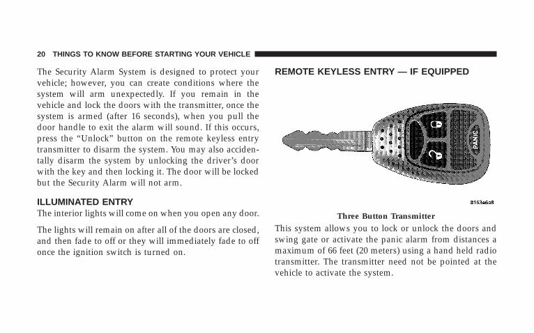
REMOTE KEYLESS ENTRY — IF EQUIPPED
This system allows you to lock or unlock the doors andswing gate or activate the panic alarm from distances amaximum of 66 feet (20 meters) using a hand held radiotransmitter. The transmitter need not be pointed at thevehicle to activate the system.
Three Button Transmitter
20 THINGS TO KNOW BEFORE STARTING YOUR VEHICLE
NOTE: The line of transmission must not be blockedwith metal objects.
To Unlock the Doors and Swing GatePress and release the “Unlock” button on the key fobonce to unlock only the driver’s door or twice to unlockall the doors and swing gate. When the “Unlock” buttonis pressed, the illuminated entry will initiate, and theparking lights will flash on twice.
The system can be programmed to unlock all the doorsupon the first “Unlock” button press by using the follow-ing procedure:
1. Press and hold the “Lock” button on a programmedkey fob.
2. Continue to hold the “Lock” button at least 4 seconds,but not longer than 10 seconds, then press and hold the“Unlock” button.
3. Release both buttons at the same time.
4. Test the feature while outside of the vehicle, bypressing the “Lock/Unlock” button on the keyfob.
NOTE: Pressing the “Lock” button on the keyfob whileyou are inside the vehicle will activate the SecurityAlarm. Opening a door with the Security Alarm activatedwill cause the alarm to sound. Press the “Unlock” buttonto deactivate the Security Alarm.
5. If the desired programming was not achieved or toreactivate this feature, repeat the above steps.
To Lock the Doors and Swing GatePress and release the “Lock” button on the transmitter tolock all doors. The turn signal lights will flash and thehorn will chirp once to acknowledge the lock signal. Ifdesired, the “Sound Horn On Lock” feature can beturned on or off by performing the following steps:
1. Press the “Lock” button for 4 to 10 seconds.
THINGS TO KNOW BEFORE STARTING YOUR VEHICLE 21
2
2. While the “Lock” button is pressed (after 4 seconds),press the PANIC button. Release both buttons.
The “Sound Horn On Lock” feature can be reactivated byrepeating this procedure.
Using The Panic AlarmTo turn the panic alarm feature ON or OFF, press andhold the PANIC button on the transmitter for at least onesecond and release. When the panic alarm is on, theheadlights and park lights will flash, the horn will pulseon and off and the interior lights will turn on.
The panic alarm will stay on for 3 minutes unless youturn it off by pressing the PANIC button a second time orif the vehicle speed is 5 mph (8 km/h) or greater.
NOTE: When you turn off the panic alarm by pressingthe PANIC button a second time, you may have to becloser to the vehicle due to the radio frequency noises ofthe system.
To Turn Off “Flash Lights With Lock”
NOTE: The Flash Lights With Lock feature can beturned on or off by performing the following steps:
1. Press the “Unlock” button for 4 to 10 seconds.
2. While the “Unlock” button is pressed, (after 4 seconds)press the “Lock” button. Release both buttons.
3. Test the flash lamps with LOCK feature while outsideof the vehicle, by pressing the “Lock” button on the keyfob with the ignition in the LOCK position, and the keyremoved.
NOTE: Pressing the “Lock” button on the key fob, whileyou are in the vehicle, will activate the Security Alarm.Opening a door with the Security Alarm activated willcause the alarm to sound. Press the “Unlock” button todeactivate the Security Alarm.
22 THINGS TO KNOW BEFORE STARTING YOUR VEHICLE
The “Flash Lights On Lock/Unlock” feature can bereactivated by repeating this procedure.
Programming Additional TransmittersVehicles will be shipped from the assembly plants withtwo key fob transmitters programmed only for thatvehicle. A total of eight fobs can be programmed for yourvehicle. Additional fobs can be programmed to yourvehicle through the use of a currently programmed fob.
NOTE: When entering program mode using that fob, allother programmed fobs will be erased and you will haveto reprogram them for your vehicle.
Use the Following procedure to program additional keyfobs if the vehicle is not equipped with Sentry Key:
1. Enter your vehicle and close all doors.
2. Fasten your seat belt (Fastening the seatbelt will cancelany chiming that may confuse you during this program-ming procedure).
3. Place the key into the ignition.
4. Turn the ignition to the ON position ( Do not start theengine ).
5. Press and hold the “Unlock” button on the key fob.
6. After holding the “Unlock” button for four seconds,also press the PANIC button within 6 seconds.
7. When a single chime is heard release both buttons. Thechime is an indication that you have successfully enteredprogram mode. All fobs that are to be programmed mustbe done so within 60 seconds of when the chime washeard.
8. Using the fob to be programmed, press and releaseboth the “Lock” and “Unlock” buttons, simultaneously.
9. A single chime will be heard.
10. Within four seconds of hearing the chime, press andrelease the “Unlock” button on the fob.
THINGS TO KNOW BEFORE STARTING YOUR VEHICLE 23
2
11. A single chime will be heard.
12. Repeat steps 8 through 10 to program up to sixadditional fobs.
13. Turn the ignition to the OFF position.
14. Your vehicle will remain in program mode up to 60seconds from when the original chime was heard. After60 seconds, all programmed fobs function normally.
NOTE: If you do not have a programmed transmitter,contact your dealer for details.
General InformationThis device complies with part 15 of FCC rules and withRS-210 of Industry Canada. Operation is subject to thefollowing conditions:
1. This device may not cause harmful interference.
2. This device must accept any interference that may bereceived including interference that may cause undesiredoperation.
NOTE: Changes or modifications not expressly ap-proved by the party responsible for compliance couldvoid the user’s authority to operate the equipment.
If your Remote Lock Control fails to operate from anormal distance, check for these two conditions.
1. Weak batteries in transmitter. The expected life ofbatteries is five years.
2. Closeness to a radio transmitter such as a radio stationtower, airport transmitter, military base, and some mobileor CB radios.
24 THINGS TO KNOW BEFORE STARTING YOUR VEHICLE
Battery ReplacementThe recommended replacement battery is CR2032.
NOTE: Perchlorate Material – special handling may apply,See www.dtsc.ca.gov/hazardouswaste/perchlorate
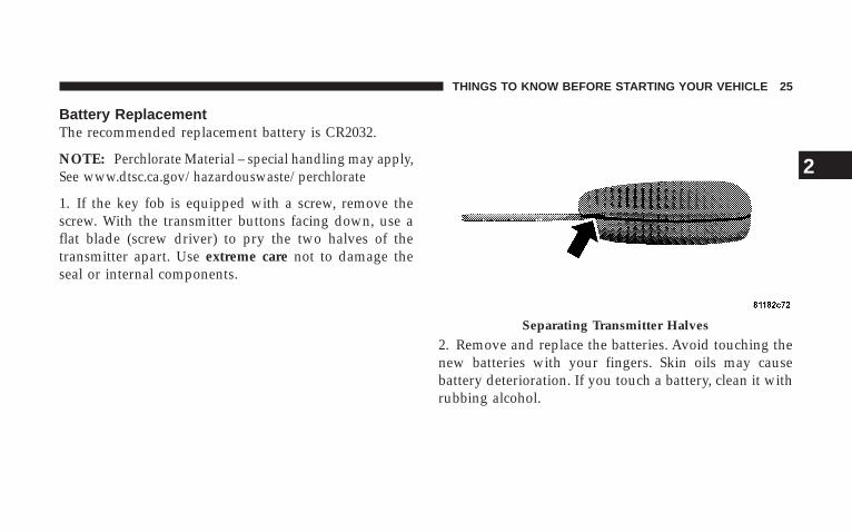
1. If the key fob is equipped with a screw, remove thescrew. With the transmitter buttons facing down, use aflat blade (screw driver) to pry the two halves of thetransmitter apart. Use extreme care not to damage theseal or internal components.
2. Remove and replace the batteries. Avoid touching thenew batteries with your fingers. Skin oils may causebattery deterioration. If you touch a battery, clean it withrubbing alcohol.
Separating Transmitter Halves
THINGS TO KNOW BEFORE STARTING YOUR VEHICLE 25
2
3. To assemble the transmitter case, snap the two halvestogether.
NOTE: If the key fob is equipped with a screw, reinstalland tighten the screw until snug.
DOORSThe vacuum fluorescent (VF) display located in theodometer area displays the word “door” as an indicationof a door ajar or door not completely closed. When thevehicle is not moving and the door is ajar or notcompletely closed, the VF display will show the word“door.”
If any other active warnings including “GATE”, “GAS-CAP”, “NOFUSE”, or “ESPOFF” are present, they will beshown in the VF display and will also continue to cycle.If the vehicle is moving, three single chimes will occur(One chime for each complete display cycle (three cyclestotal). After this, the display will continue to cycle only(no chimes).
If the trip/reset button is pressed while the VF warningsare being displayed, the VF display will revert back toonly displaying the odometer/trip odometer mileage.
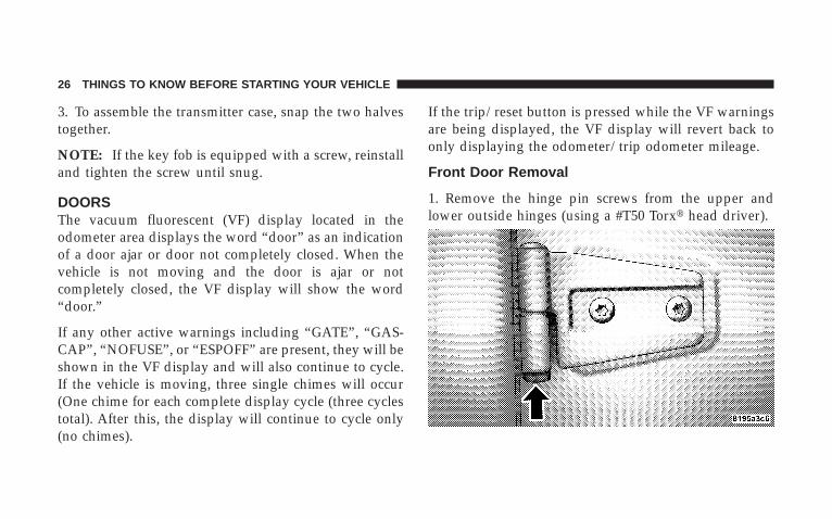
Front Door Removal
1. Remove the hinge pin screws from the upper andlower outside hinges (using a #T50 Torx� head driver).
26 THINGS TO KNOW BEFORE STARTING YOUR VEHICLE
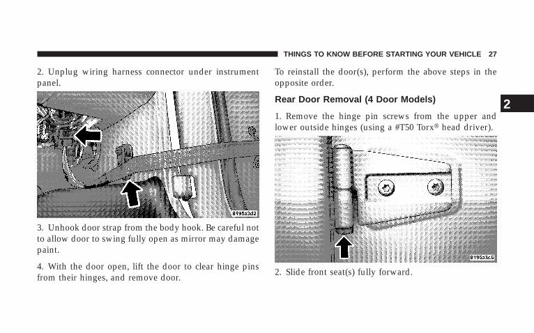
2. Unplug wiring harness connector under instrumentpanel.
3. Unhook door strap from the body hook. Be careful notto allow door to swing fully open as mirror may damagepaint.
4. With the door open, lift the door to clear hinge pinsfrom their hinges, and remove door.
To reinstall the door(s), perform the above steps in theopposite order.
Rear Door Removal (4 Door Models)
1. Remove the hinge pin screws from the upper andlower outside hinges (using a #T50 Torx� head driver).
2. Slide front seat(s) fully forward.
THINGS TO KNOW BEFORE STARTING YOUR VEHICLE 27
2
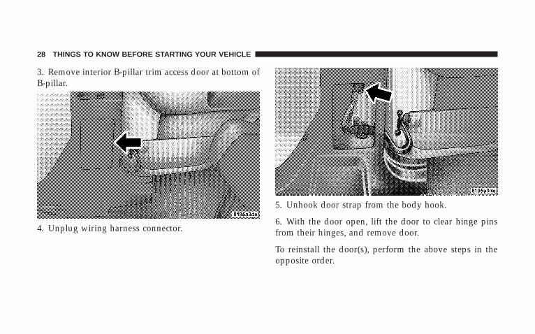
3. Remove interior B-pillar trim access door at bottom ofB-pillar.
4. Unplug wiring harness connector.
5. Unhook door strap from the body hook.
6. With the door open, lift the door to clear hinge pinsfrom their hinges, and remove door.
To reinstall the door(s), perform the above steps in theopposite order.
28 THINGS TO KNOW BEFORE STARTING YOUR VEHICLE
DOOR LOCKSThe vacuum fluorescent (VF) display located in theodometer area displays the word “door” as an indicationof a door ajar or door not completely closed. When thevehicle is not moving and the door is ajar or notcompletely closed, the VF display will show the word“door.”
If any other active warnings including “GATE”, “GAS-CAP”, “NOFUSE”, or “ESPOFF” are present, they will beshown in the VF display and will also continue to cycle.If the vehicle is moving, three single chimes will occur
(One chime for each complete display cycle (three cyclestotal). After this, the display will continue to cycle only(no chimes).
If the trip/reset button is pressed while the VF warningsare being displayed, the VF display will revert back toonly displaying the odometer/trip odometer mileage.
NOTE: The ignition key that is used to start the vehicleis used to lock or unlock the doors, glove box, swing gate,and console storage.
THINGS TO KNOW BEFORE STARTING YOUR VEHICLE 29
2
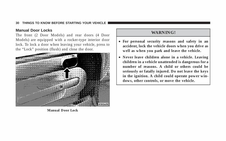
Manual Door LocksThe front (2 Door Models) and rear doors (4 DoorModels) are equipped with a rocker-type interior doorlock. To lock a door when leaving your vehicle, press tothe “Lock” position (flush) and close the door.
WARNING!
• For personal security reasons and safety in anaccident, lock the vehicle doors when you drive aswell as when you park and leave the vehicle.
• Never leave children alone in a vehicle. Leavingchildren in a vehicle unattended is dangerous for anumber of reasons. A child or others could beseriously or fatally injured. Do not leave the keysin the ignition. A child could operate power win-dows, other controls, or move the vehicle.
Manual Door Lock
30 THINGS TO KNOW BEFORE STARTING YOUR VEHICLE
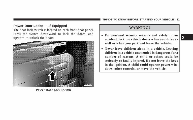
Power Door Locks — If EquippedThe door lock switch is located on each front door panel.Press the switch downward to lock the doors, andupward to unlock the doors.
WARNING!
• For personal security reasons and safety in anaccident, lock the vehicle doors when you drive aswell as when you park and leave the vehicle.
• Never leave children alone in a vehicle. Leavingchildren in a vehicle unattended is dangerous for anumber of reasons. A child or others could beseriously or fatally injured. Do not leave the keysin the ignition. A child could operate power win-dows, other controls, or move the vehicle.
Power Door Lock Switch
THINGS TO KNOW BEFORE STARTING YOUR VEHICLE 31
2
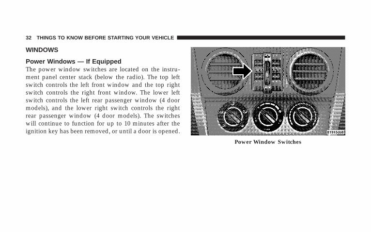
WINDOWS
Power Windows — If EquippedThe power window switches are located on the instru-ment panel center stack (below the radio). The top leftswitch controls the left front window and the top rightswitch controls the right front window. The lower leftswitch controls the left rear passenger window (4 doormodels), and the lower right switch controls the rightrear passenger window (4 door models). The switcheswill continue to function for up to 10 minutes after theignition key has been removed, or until a door is opened.
Power Window Switches
32 THINGS TO KNOW BEFORE STARTING YOUR VEHICLE
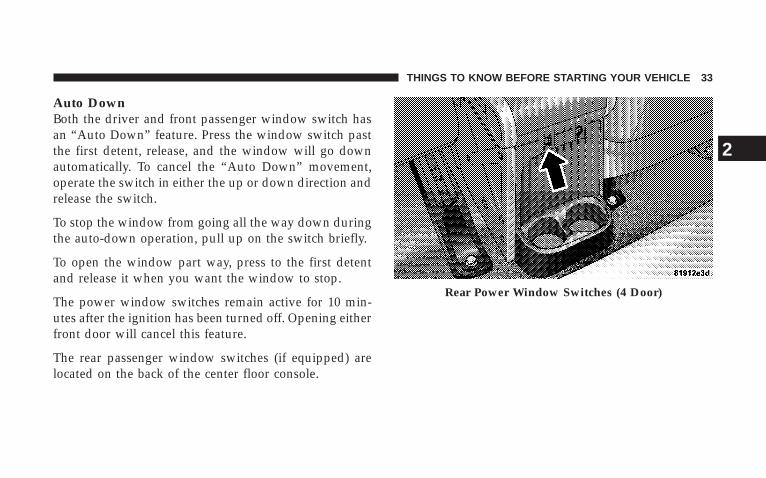
Auto DownBoth the driver and front passenger window switch hasan “Auto Down” feature. Press the window switch pastthe first detent, release, and the window will go downautomatically. To cancel the “Auto Down” movement,operate the switch in either the up or down direction andrelease the switch.
To stop the window from going all the way down duringthe auto-down operation, pull up on the switch briefly.
To open the window part way, press to the first detentand release it when you want the window to stop.
The power window switches remain active for 10 min-utes after the ignition has been turned off. Opening eitherfront door will cancel this feature.
The rear passenger window switches (if equipped) arelocated on the back of the center floor console.
Rear Power Window Switches (4 Door)
THINGS TO KNOW BEFORE STARTING YOUR VEHICLE 33
2
Window Lockout Switch (4 Door Models Only)The window lockout switch (located between the win-dow switches) allows you to disable the rear windowswitches that are located on the back of the center floorconsole. To disable the window controls, press the win-dow lockout button downward. To enable the windowcontrols, press the window lockout button upward.
Wind Buffeting
Wind buffeting can be described as the perception ofpressure on the ears or a helicopter type sound in theears. Your vehicle may exhibit wind buffeting with thewindows down in certain open or partially open posi-tions. This is a normal occurrence and can be minimizedby adjusting window opening.
REAR SWING GATEThe vacuum fluorescent (VF) display located in theodometer area displays the word “gATE” as an indica-tion of when the swing gate is not completely closed.When the vehicle is not moving, and the swing gate is notcompletely closed, the VF display will show the word“gATE.”
If any other active warnings are present, they will beshown in the VF display and will also continue to cycle.If the vehicle is moving, three single chimes will occur ifthe rear swing gate is open (one chime for each completedisplay cycle). After this, the VF display will continue tosequence only (no chimes).
If the trip/reset button is pressed while the VF warningsare being displayed, the VF display will revert back toonly displaying the odometer/trip odometer mileage.
34 THINGS TO KNOW BEFORE STARTING YOUR VEHICLE
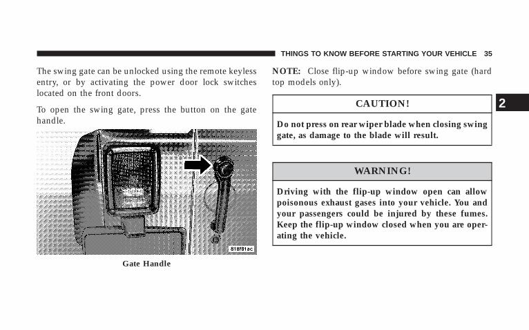
The swing gate can be unlocked using the remote keylessentry, or by activating the power door lock switcheslocated on the front doors.
To open the swing gate, press the button on the gatehandle.
NOTE: Close flip-up window before swing gate (hardtop models only).
CAUTION!
Do not press on rear wiper blade when closing swinggate, as damage to the blade will result.
WARNING!
Driving with the flip-up window open can allowpoisonous exhaust gases into your vehicle. You andyour passengers could be injured by these fumes.Keep the flip-up window closed when you are oper-ating the vehicle.
Gate Handle
THINGS TO KNOW BEFORE STARTING YOUR VEHICLE 35
2
OCCUPANT RESTRAINTSSome of the most important safety features in yourvehicle are the restraint systems. These include the frontand rear seat belts for the driver and all passengers, frontairbags for both the driver and front passenger, and sideairbags (if equipped) for both the driver and frontpassenger. If you will be carrying children too small foradult-size belts, your seat belts can also be used to holdinfant and child restraint systems.
NOTE: The front airbags have a multi stage inflatordesign. This allows the airbag to have different rates ofinflation that are based on collision severity.
Please pay close attention to the information in thissection. It tells you how to use your restraint systemproperly to keep you and your passengers as safe aspossible.
WARNING!
In a collision, you and your passengers can sufferinjuries, including fatalities, if you are not properlybuckled up. You can strike the interior of yourvehicle or other passengers, or you can be thrown outof the vehicle. Always be sure you and others in yourvehicle are buckled up properly.
Buckle up even though you are an excellent driver, evenon short trips. Someone on the road may be a poor driverand cause a collision that includes you. This can happenfar away from home or on your own street.
36 THINGS TO KNOW BEFORE STARTING YOUR VEHICLE
Research has shown that seat belts save lives, and thatthey can reduce the seriousness of injuries in a collision.Some of the worst injuries happen when people arethrown from the vehicle. Seat belts reduce the possibilityof ejection and the risk of injury caused by striking theinside of the vehicle. Everyone in a motor vehicle shouldbe belted at all times to reduce or prevent injuries.
Lap/Shoulder BeltsAll seating positions in your vehicle have combinationlap/shoulder belts. The belt webbing retractor is de-signed to lock during very sudden stops or collisions.This feature allows the shoulder part of the belt to movefreely with you under normal conditions. But in a colli-sion, the belt will lock and reduce the risk of your strikingthe inside of the vehicle or being thrown out.
WARNING!
• It is extremely dangerous to ride in a cargo area,inside or outside of a vehicle. In a collision, peopleriding in these areas are more likely to be seri-ously injured or killed.
• Do not allow people to ride in any area of yourvehicle that is not equipped with seats and seatbelts.
• Be sure everyone in your vehicle is in a seat usinga seat belt properly.
THINGS TO KNOW BEFORE STARTING YOUR VEHICLE 37
2
WARNING!
• Wearing a seat belt incorrectly is dangerous. Seatbelts are designed to go around the large bones ofyour body. These are the strongest parts of yourbody and take the forces of a collision the best.Wearing your belt in the wrong place could makeyour injuries in a collision much worse. You mightsuffer internal injuries, or you could even slide outof part of the belt. Follow these instructions towear your seat belt safely and to keep your pas-sengers safe, too.
• Two people should never be belted into a singleseat belt. People belted together can crash into oneanother in an accident, hurting one another badly.Never use a lap/shoulder belt or a lap belt for morethan one person, no matter what their size.
Lap/Shoulder Belt Operating Instructions
1. Enter the vehicle and close the door. Sit back andadjust the seat.
2. The seat belt latch plate is above the back of the frontseat, next to your arm in the rear seat. Grasp the latchplate and pull out the belt. Slide the latch plate up thewebbing as far as necessary to allow the belt to go aroundyour lap.
38 THINGS TO KNOW BEFORE STARTING YOUR VEHICLE
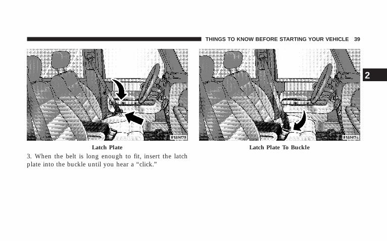
3. When the belt is long enough to fit, insert the latchplate into the buckle until you hear a “click.”
Latch Plate Latch Plate To Buckle
THINGS TO KNOW BEFORE STARTING YOUR VEHICLE 39
2
WARNING!
A belt that is buckled into the wrong buckle will notprotect you properly. The lap portion could ride too highon your body, possibly causing internal injuries. Alwaysbuckle your belt into the buckle nearest you.
A belt that is loose will not protect you as well. In asudden stop you could move too far forward, increasingthe possibility of injury. Wear your seat belt snugly.
A belt that is worn under your arm is very dangerous.Your body could strike the inside surfaces of the vehiclein a collision, increasing head and neck injury. A beltworn under the arm can cause internal injuries. Ribsaren’t as strong as shoulder bones. Wear the belt overyour shoulder so that the strongest bones will take theforce in a collision.
A shoulder belt placed behind will not protect you frominjury during a collision. You are more likely to hit yourhead in a collision if you do not wear your shoulder belt.The lap and shoulder belt are meant to be used together.
4. Position the lap belt across your thighs, below yourabdomen. To remove slack in the lap belt portion, pull upon the shoulder belt. To loosen the lap belt if it is too tight,tilt the latch plate and pull on the lap belt. A snug beltreduces the risk of sliding under the belt in a collision.
40 THINGS TO KNOW BEFORE STARTING YOUR VEHICLE
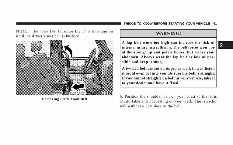
NOTE: The “Seat Belt Indicator Light” will remain onuntil the driver’s seat belt is buckled.
WARNING!
A lap belt worn too high can increase the risk ofinternal injury in a collision. The belt forces won’t beat the strong hip and pelvic bones, but across yourabdomen. Always wear the lap belt as low as pos-sible and keep it snug.
A twisted belt cannot do its job as well. In a collisionit could even cut into you. Be sure the belt is straight.If you cannot straighten a belt in your vehicle, take itto your dealer and have it fixed.
5. Position the shoulder belt on your chest so that it iscomfortable and not resting on your neck. The retractorwill withdraw any slack in the belt.
Removing Slack From Belt
THINGS TO KNOW BEFORE STARTING YOUR VEHICLE 41
2
6. To release the belt, push the red button on the buckle.The belt will automatically retract to its stowed position.If necessary, slide the latch plate down the webbing toallow the belt to retract fully.
WARNING!
A frayed or torn belt could rip apart in a collision andleave you with no protection. Inspect the belt systemperiodically, checking for cuts, frays, or loose parts.Damaged parts must be replaced immediately. Donot disassemble or modify the system. Seat beltassemblies must be replaced after a collision if theyhave been damaged (bent retractor, torn webbing,etc.).
Rear Center Lap/Shoulder Belt RetractorLock-OutThis feature is designed to lock the retractor wheneverthe 60% rear seat back is not fully latched. This preventssomeone from wearing the rear center lap/shoulder beltwhen the rear seat back is not fully latched.
NOTE:• If the rear center lap/shoulder belt cannot be pulled
out, check that the rear seat back is fully latched.
• If the rear seat back is properly latched and the rearcenter lap/shoulder belt still cannot be pulled out, theAutomatic-Locking Retractor (ALR) system may beactivated. To reset this feature you must let all of thebelt webbing return into the retractor. You will not beable to pull out more webbing until all of the webbinghas been returned back into the retractor.
42 THINGS TO KNOW BEFORE STARTING YOUR VEHICLE
WARNING!
The rear center lap/shoulder belt is equipped with alock-out feature to ensure that the rear seat back is inthe fully upright and locked position when occupied.If the rear seat back is not fully upright and lockedand the rear center lap/shoulder belt can be pulledout of the retractor, the vehicle should immediatelybe taken to your dealer for service. Failure to followthis warning could result in serious or fatal injury.
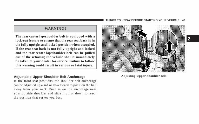
Adjustable Upper Shoulder Belt AnchorageIn the front seat positions, the shoulder belt anchoragecan be adjusted upward or downward to position the beltaway from your neck. Push in on the anchorage nearyour outside shoulder and slide it up or down to reachthe position that serves you best.
Adjusting Upper Shoulder Belt
THINGS TO KNOW BEFORE STARTING YOUR VEHICLE 43
2
WARNING!
Position the shoulder belt height adjusters so that thebelt rests across the middle of your shoulder. Failureto adjust the safety belt properly could reduce theeffectiveness of the seat belt and increase the risk ofinjury in a collision.
As a guide, if you are shorter than average, you willprefer a lower position, and if you are taller than average,you’ll prefer a higher position. When you release theanchorage, try to move it up or down to make sure thatit is locked in position.
Seat Belt PretensionersThe driver and front passenger seat belts are equippedwith a pretensioning device that is designed to removeany slack from the seat belt systems in the event of acollision. This device improves the performance of theseat belt by assuring that the belt is tight around theoccupant early in a collision. Pretensioners work for allsize occupants, including those in child restraints.
NOTE: These devices are not a substitute for proper seatbelt placement by the occupant. The seat belt must still beworn snugly and positioned properly.
The pretensioners are triggered by the Occupant Re-straint Control (ORC) Module. Like the front airbags, thepretensioners are a single use item. After a collision thatis severe enough to deploy the airbags and pretensioners,they must be replaced.
44 THINGS TO KNOW BEFORE STARTING YOUR VEHICLE
Enhanced Seat Belt Use Reminder System(BeltAlert)If the driver or front passenger seat belt has not beenbuckled within 60 seconds of starting the vehicle and ifthe vehicle speed is greater than 5 mph (8 km/h), theEnhanced Warning System (BeltAlert) will alert thedriver to buckle their seat belt. The driver should alsoinstruct all other occupants to buckle their seat belts.Once the warning is triggered, the Enhanced WarningSystem (BeltAlert) will continue to chime and flash theSeat Belt Warning Light for 96 seconds or until the driveror front passenger seat belt is buckled.
The Enhanced Warning System (BeltAlert) will be reacti-vated if the driver or front passenger seat belt is unbuck-led for more than 10 seconds and the vehicle speed isgreater than 5 mph (8 km/h).
The Enhanced Warning System (BeltAlert) can be en-abled or disabled by your authorized dealer or byfollowing these steps:
NOTE: The following steps must occur within the first60 seconds of the ignition switch being turned to the ONor START position. The manufacturer does not recom-mend deactivating the Enhanced Warning System(BeltAlert).
1. Turn the ignition switch to the OFF position, andbuckle the driver or front passenger seat belt.
2. Turn the ignition key to the ACCESSORY/RUN posi-tion (engine does not need to be running), and wait forthe Seat Belt Warning Light to turn off.
3. Within 60 seconds of starting the vehicle, unbuckleand then re-buckle the driver or front passenger seat beltat least three times within 10 seconds, ending with theseat belt buckled.
THINGS TO KNOW BEFORE STARTING YOUR VEHICLE 45
2
4. Turn the ignition key to the OFF position. A singlechime will sound to signify that you have successfullycompleted the programming.
The Enhanced Warning System (BeltAlert) can be reacti-vated by repeating this procedure.
NOTE: Although the Enhanced Warning System(BeltAlert) has been deactivated, the Seat Belt WarningLight will continue to illuminate while the driver’s seatbelt remains unfastened.
Seat Belts And Pregnant WomenWe recommend that pregnant women use seat beltsthroughout their pregnancy. Keeping the mother safe isthe best way to keep the baby safe.
Pregnant women should wear the lap part of the beltacross the thighs and as snug across the hips as possible.Keep the belt low so that it does not come across theabdomen. That way the strong bones of the hips will takethe force if there is a collision.
Seat Belt ExtenderIf a seat belt is too short, even when fully extended andwhen the adjustable upper shoulder belt anchorage (ifequipped) is in its lowest position, your dealer canprovide you with a seat belt extender. This extendershould be used only if the existing belt is not longenough. When it is not required, remove the extenderand store it.
46 THINGS TO KNOW BEFORE STARTING YOUR VEHICLE
WARNING!
Using a seat belt extender when not needed canincrease the risk of injury in a collision. Only usewhen the seat belt is not long enough when it is wornlow and snug, and in the recommended seatingpositions. Remove and stow the seat belt extenderwhen not needed.
Driver And Front Passenger SupplementalRestraint Systems (SRS)
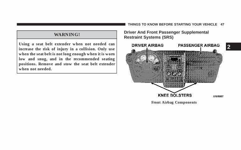
Front Airbag Components
THINGS TO KNOW BEFORE STARTING YOUR VEHICLE 47
2
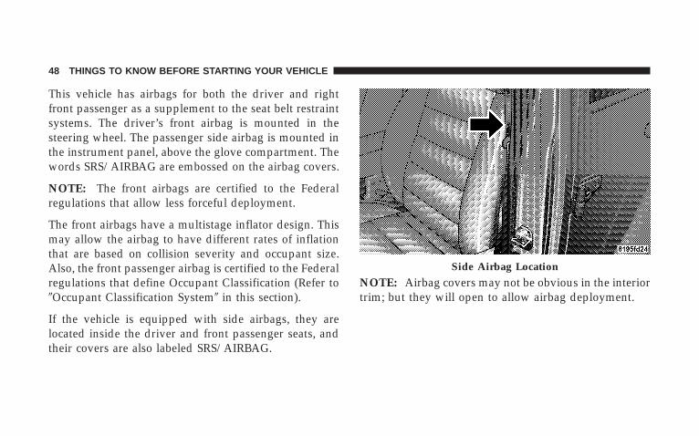
This vehicle has airbags for both the driver and rightfront passenger as a supplement to the seat belt restraintsystems. The driver’s front airbag is mounted in thesteering wheel. The passenger side airbag is mounted inthe instrument panel, above the glove compartment. Thewords SRS/AIRBAG are embossed on the airbag covers.
NOTE: The front airbags are certified to the Federalregulations that allow less forceful deployment.
The front airbags have a multistage inflator design. Thismay allow the airbag to have different rates of inflationthat are based on collision severity and occupant size.Also, the front passenger airbag is certified to the Federalregulations that define Occupant Classification (Refer to�Occupant Classification System� in this section).
If the vehicle is equipped with side airbags, they arelocated inside the driver and front passenger seats, andtheir covers are also labeled SRS/AIRBAG.
NOTE: Airbag covers may not be obvious in the interiortrim; but they will open to allow airbag deployment.
Side Airbag Location
48 THINGS TO KNOW BEFORE STARTING YOUR VEHICLE
WARNING!
• Do not put anything on or around the front airbag coversor attempt to manually open them. You may damage theairbags and you could be injured because the airbags areno longer functional. These protective covers for theairbag cushions are designed to open only when theairbags are inflating.
• If your vehicle is equipped with side airbags, do not useaccessory seat covers or place objects between you andthe side airbags; the performance could be adverselyaffected and/or objects could be pushed into you, caus-ing serious injury.
• If your vehicle is equipped with side airbags, do notattach cup holders or any other objects on or around thedoor. The inflating side airbag could drive the objectsinto occupants, causing serious injury.
• Do not cover or place items on the airbag covers. Theseitems may cause serious injury during inflation.
• Do not store or place items under the front seats. Youmay damage the airbag wiring harnesses.
The front airbags have a multi stage inflator design. Thisallows the airbag to have different rates of inflation thatare based on collision severity. Along with the seat belts,front airbags work with the instrument panel knee bol-sters to provide improved protection for the driver andfront passenger. Side airbags also work with seat belts toimprove occupant protection.
The seat belts are designed to protect you in many typesof collisions. The front airbags deploy in moderate tosevere frontal collisions.
NOTE: The passenger front airbag may not deploy evenwhen the driver front airbag has if the Occupant Classi-fication System (refer to �Occupant Classification System�in this section) has determined the passenger seat isempty or is occupied by someone that is classified in the�small child� category.
If your vehicle is so equipped, the side airbag on thecrash side of the vehicle is triggered in moderate to
THINGS TO KNOW BEFORE STARTING YOUR VEHICLE 49
2

severe side collisions. In certain types of collisions, boththe front and side airbags may be triggered. But even incollisions where the airbags work, you need the seat beltsto keep you in the right position for the airbags to protectyou properly.
Here are some simple steps you can take to minimize therisk of harm from a deploying airbag.
1. Children 12 years and under should always ridebuckled up in a rear seat.
Infants in rear facing child restraints should NEVER ridein the front seat of a vehicle with a passenger airbag. Anairbag deployment could cause severe injury or death toinfants in that position.
Children that are not big enough to properly wear thevehicle seat belt should be secured in the rear seat, in a
child restraint or belt-positioning booster seat. Olderchildren who do not use child restraints or belt-positioning booster seats should ride properly buckledup in the rear seat. Never allow children to slide theshoulder belt behind them or under their arm.
If a child from 1 to 12 years old must ride in the frontpassenger seat because the vehicle is crowded, move theseat as far back as possible, and use the proper childrestraint. See “Child Restraint” in this section.
You should read the instructions provided with yourchild restraint to make sure that you are using it properly.
2. All occupants should use their lap and shoulder beltsproperly.
50 THINGS TO KNOW BEFORE STARTING YOUR VEHICLE
3. The driver and front passenger seats should be movedback as far as practical to allow the front airbags room toinflate.
4. If your vehicle has side airbags, do not lean against thedoor, airbags will inflate forcefully into the space be-tween you and the door.
5. If the airbag system in this vehicle needs to bemodified to accommodate a disabled person, contact theCustomer Center. Phone numbers are provided under “IfYou Need Assistance” in Section 9 of this manual.
WARNING!
• Relying on the airbags alone could lead to moresevere injuries in a collision. The airbags workwith your seat belt to restrain you properly. Insome collisions the airbags won’t deploy at all.Always wear your seat belts even though you haveairbags.
• Being too close to the steering wheel or instrumentpanel during airbag deployment could cause seri-ous injury. Airbags need room to inflate. Sit back,comfortably extending your arms to reach thesteering wheel or instrument panel.
• If the vehicle has side airbags, they also need roomto inflate. Do not lean against the door. Sit uprightin the center of the seat.
THINGS TO KNOW BEFORE STARTING YOUR VEHICLE 51
2
Airbag System ComponentsThe airbag system consists of the following:
• Occupant Restraint Control Module
• Airbag Warning Light
• Driver Airbag
• Passenger Airbag
• Front Seat Mounted Side Airbags (If Equipped)
• Steering Wheel and Column
• Instrument Panel
• Interconnecting Wiring
• Knee Impact Bolsters
• Front Acceleration Sensors
• Driver and Front Passenger Seat Belt Pretensioner
• Occupant Classification System (OCS) — Front Pas-senger Seat Only
− Occupant Classification Module
− Passenger Airbag Disable (PAD) Indicator Light
− Weight Sensors
How The Airbag System Works
• The Occupant Restraint Control (ORC) Module de-termines if a frontal, or side collision is severe enoughto require the front and/or side airbags to inflate. Thefront airbag inflators are designed to provide differentrates of airbag inflation from direction provided by theORC. The ORC may also modify the rate of inflationbased on the occupant size provided by the OccupantClassification Module.
52 THINGS TO KNOW BEFORE STARTING YOUR VEHICLE
The ORC also monitors the readiness of the electronicparts of the system whenever the ignition switch is inthe START or ON positions. These include all of theitems listed above except the knee bolster, the instru-ment panel, and the steering wheel and column. If thekey is in the LOCK position, in the ACC position, ornot in the ignition, the airbags are not on and will notinflate.
Also, the ORC turns on the “Airbag WarningLight” and “PAD Indicator Light” for 6 to 8seconds for a self-check when the ignition isfirst turned on. After the self-check, the
“Airbag Warning Light” will turn off. The “PADIndicator Light” will function normally (Refer to �Pas-senger Airbag Disable (PAD) Indicator Light� in thissection). If the ORC detects a malfunction in any partof the system, it turns on the “Airbag Warning Light”
either momentarily or continuously. A single chimewill sound if the light comes on again after initial startup.
WARNING!
Ignoring the “Airbag Warning Light” in your instru-ment panel could mean you won’t have the airbags toprotect you in a collision. If the light does not comeon, stays on after you start the vehicle, or if it comeson as you drive, have the airbag system checked rightaway.
THINGS TO KNOW BEFORE STARTING YOUR VEHICLE 53
2
• The Occupant Classification System (OCS) is part ofa Federally regulated safety system required for thisvehicle. It is designed to turn off the front passengerairbag in the unlikely event that a rear-facing infantseat is in the front passenger seat.
NOTE: Children 12 years and under should always ridebuckled up in a rear seat in an appropriate child restraint.
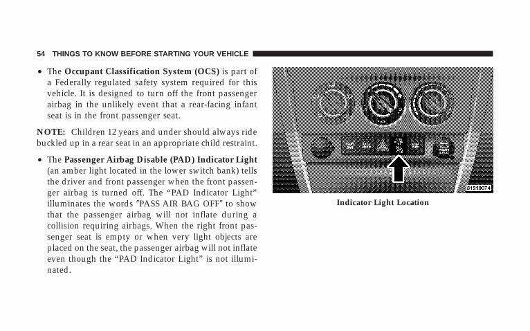
• The Passenger Airbag Disable (PAD) Indicator Light(an amber light located in the lower switch bank) tellsthe driver and front passenger when the front passen-ger airbag is turned off. The “PAD Indicator Light”illuminates the words �PASS AIR BAG OFF� to showthat the passenger airbag will not inflate during acollision requiring airbags. When the right front pas-senger seat is empty or when very light objects areplaced on the seat, the passenger airbag will not inflateeven though the “PAD Indicator Light” is not illumi-nated.
Indicator Light Location
54 THINGS TO KNOW BEFORE STARTING YOUR VEHICLE
The “PAD Indicator Light” should not be illuminatedwhen teenagers, most children in a forward-facingchild restraint or booster seats, most children that canproperly wear the vehicle’s seat belt, and when anadult passenger is properly seated in the front passen-ger seat. In this case, the airbag is ready to be inflatedif a collision requiring an airbag occurs.
For almost all properly installed rear facing child re-straints, the “PAD Indicator Light” will be illuminatedindicating that the front passenger airbag is turned offand will not inflate. If the “PAD Indicator Light” is notilluminated, DO NOT assume the airbag is turned offand move the child restraint to the rear seat. A deployingpassenger airbag can cause death or serious injury to achild in a rear facing infant seat.
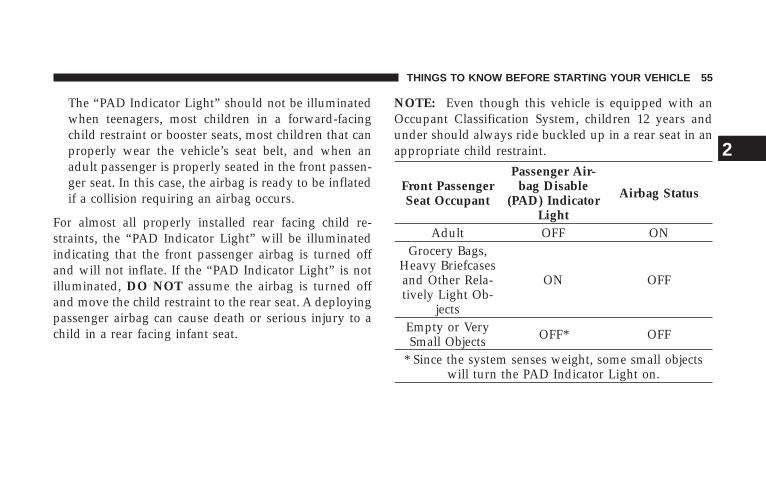
NOTE: Even though this vehicle is equipped with anOccupant Classification System, children 12 years andunder should always ride buckled up in a rear seat in anappropriate child restraint.
Front PassengerSeat Occupant
Passenger Air-bag Disable
(PAD) IndicatorLight
Airbag Status
Adult OFF ONGrocery Bags,
Heavy Briefcasesand Other Rela-tively Light Ob-
jects
ON OFF
Empty or VerySmall Objects OFF* OFF
* Since the system senses weight, some small objectswill turn the PAD Indicator Light on.
THINGS TO KNOW BEFORE STARTING YOUR VEHICLE 55
2
The OCS classifies an occupant using weight sensorsmounted in the base of the front passenger seat. Anyweight on the seat will be sensed by the system. Objectshanging on the seat or other passengers pushing downon the seat will also be sensed. The weight of an adultwill cause the system to turn the airbag on. In this case,the OCS has classified the occupant of the seat as anadult. An adult occupant needs to sit in a normal position(with their feet on or near the floor) in order to beproperly classified. Reclining the seat back too far maychange how an occupant is classified by the OCS.
Drivers and adult passengers should verify that the“PAD Indicator Light” is not illuminated when an adultis riding in the front passenger seat. If an adult occu-pant’s weight is transferred to another part of the vehicle(like the door or instrument panel), the weight sensors inthe seat may not properly classify the occupant. Objectslodged under the seat or between the seat and the centerconsole can prevent the occupant’s weight from being
measured properly and may result in the occupant beingimproperly classified. Ensure that the front passengerseat back does not touch anything placed on the back seatbecause this can also affect occupant classification. Also,if you fold down the rear seat check to be sure it doesn’ttouch the front passenger seat.
If the front passenger seat is damaged in any way, itshould only be serviced by an authorized dealer. If theseat is removed (or even if the seat attachment bolts areloosened or tightened in any way), take the vehicle to anauthorized dealer.
If there is a fault present in the OCS, the “Airbag WarningLight” (a red light located in the center of the instrumentcluster directly in front of the driver) will be turned on.This indicates that you should take the vehicle to anauthorized dealer. The “Airbag Warning Light” is turnedon whenever there is fault that can affect the operation ofthe airbag system. If there is a fault present in the OCS,
56 THINGS TO KNOW BEFORE STARTING YOUR VEHICLE
both the “PAD Indicator Light” and the “Airbag WarningLight” are illuminated to show that the passenger airbagis turned off until the fault is cleared. If an object islodged under the seat and interferes with operation ofthe weight sensors, a fault will occur which turns on boththe “PAD Indicator Light” and the “Airbag WarningLight.” Once the lodged object is removed, the fault willbe automatically cleared after a short period of time.
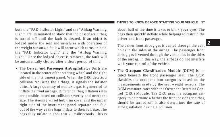
• The Driver and Passenger Airbag/Inflator Units arelocated in the center of the steering wheel and the rightside of the instrument panel. When the ORC detects acollision requiring the airbags, it signals the inflatorunits. A large quantity of nontoxic gas is generated toinflate the front airbags. Different airbag inflation ratesare possible, based on collision severity and occupantsize. The steering wheel hub trim cover and the upperright side of the instrument panel separate and foldout of the way as the bags inflate to their full size. Thebags fully inflate in about 50–70 milliseconds. This is
about half of the time it takes to blink your eyes. Thebags then quickly deflate while helping to restrain thedriver and front passenger.
The driver front airbag gas is vented through the ventholes in the sides of the airbag. The passenger frontairbag gas is vented through the vent holes in the sidesof the airbag. In this way, the airbags do not interferewith your control of the vehicle.
• The Occupant Classification Module (OCM) is lo-cated beneath the front passenger seat. The OCMclassifies the occupant into categories based on themeasurements made by the seat weight sensors. TheOCM communicates with the Occupant Restraint Con-trol (ORC) Module. The ORC uses the occupant cat-egory to determine whether the front passenger airbagshould be turned off. It also determines the rate ofairbag inflation during a collision.
THINGS TO KNOW BEFORE STARTING YOUR VEHICLE 57
2
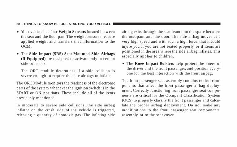
• Your vehicle has four Weight Sensors located betweenthe seat and the floor pan. The weight sensors measureapplied weight and transfers that information to theOCM.
• The Side Impact (SRS) Seat Mounted Side Airbags(If Equipped) are designed to activate only in certainside collisions.
The ORC module determines if a side collision issevere enough to require the side airbags to inflate.
The ORC Module monitors the readiness of the electronicparts of the system whenever the ignition switch is in theSTART or ON positions. These include all of the itemspreviously mentioned.
In moderate to severe side collisions, the side airbaginflator on the crash side of the vehicle is triggered,releasing a quantity of nontoxic gas. The inflating side
airbag exits through the seat seam into the space betweenthe occupant and the door. The side airbag moves at avery high speed and with such a high force, that it couldinjure you if you are not seated properly, or if items arepositioned in the area where the side airbag inflates. Thisespecially applies to children.
• The Knee Impact Bolsters help protect the knees ofthe driver and the front passenger, and position every-one for the best interaction with the front airbag.
The front passenger seat assembly contains critical com-ponents that affect the front passenger airbag deploy-ment. Correctly functioning front passenger seat compo-nents are critical for the Occupant Classification System(OCS) to properly classify the front passenger and calcu-late the proper airbag deployment. Do not make anymodifications to the front passenger seat components,assembly, or to the seat cover.
58 THINGS TO KNOW BEFORE STARTING YOUR VEHICLE
The following requirements must be strictly adhered to:
• Do not modify the front passenger seat assembly orcomponents in any way.
• Do not modify the front seat center console or centerposition seat in any way.
• Do not use prior or future model year seat covers notdesignated for the specific model being repaired. Al-ways use the correct seat cover specified for thevehicle.
• Do not replace the seat cover with an aftermarket seatcover.
• Do not add a secondary seat cover other than thoseapproved by DaimlerChrysler/Mopar.
• At no time should any supplemental restraint system(SRS) component or SRS related component or fas-tener be modified or replaced with any part exceptthose which are approved by DaimlerChrysler/Mopar.
WARNING!
Unapproved modifications or service procedures tothe front passenger seat assembly, its related compo-nents, or seat cover may inadvertently change theairbag deployment in case of a frontal crash. Thiscould result in death or serious injury to the frontseat passenger if the vehicle is involved in an acci-dent. A modified vehicle may not comply with re-quired Federal Motor Vehicle Safety Standards(FMVSS).
THINGS TO KNOW BEFORE STARTING YOUR VEHICLE 59
2
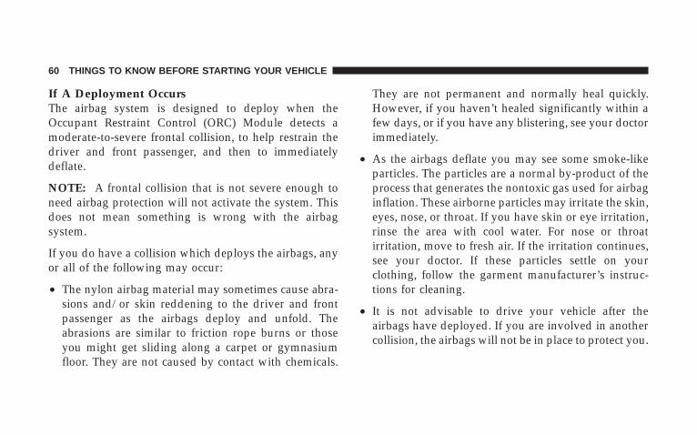
If A Deployment OccursThe airbag system is designed to deploy when theOccupant Restraint Control (ORC) Module detects amoderate-to-severe frontal collision, to help restrain thedriver and front passenger, and then to immediatelydeflate.
NOTE: A frontal collision that is not severe enough toneed airbag protection will not activate the system. Thisdoes not mean something is wrong with the airbagsystem.
If you do have a collision which deploys the airbags, anyor all of the following may occur:
• The nylon airbag material may sometimes cause abra-sions and/or skin reddening to the driver and frontpassenger as the airbags deploy and unfold. Theabrasions are similar to friction rope burns or thoseyou might get sliding along a carpet or gymnasiumfloor. They are not caused by contact with chemicals.
They are not permanent and normally heal quickly.However, if you haven’t healed significantly within afew days, or if you have any blistering, see your doctorimmediately.
• As the airbags deflate you may see some smoke-likeparticles. The particles are a normal by-product of theprocess that generates the nontoxic gas used for airbaginflation. These airborne particles may irritate the skin,eyes, nose, or throat. If you have skin or eye irritation,rinse the area with cool water. For nose or throatirritation, move to fresh air. If the irritation continues,see your doctor. If these particles settle on yourclothing, follow the garment manufacturer’s instruc-tions for cleaning.
• It is not advisable to drive your vehicle after theairbags have deployed. If you are involved in anothercollision, the airbags will not be in place to protect you.
60 THINGS TO KNOW BEFORE STARTING YOUR VEHICLE
WARNING!
Deployed airbags and seat belt pretensioners cannotprotect you in another collision. Have the airbags,seat belt pretensioner, and seat belt retractor assem-bly, replaced by an authorized dealer as soon aspossible. Also, have the Occupant Classification Sys-tem serviced as well.
Enhanced Accident Response FeatureIf the airbags deploy after an impact and the electricalsystem remains functional, vehicles equipped withpower door locks will unlock automatically. In addition,approximately 5 seconds after the vehicle has stoppedmoving, the interior lights will illuminate to aid visibility.
NOTE: The interior lights can only be deactivated if thekey is removed from the ignition switch or the vehicle isdriven.
Maintaining Your Airbag System
WARNING!
• Modifications to any part of the airbag system could cause it to fail when youneed it. You could be injured if the airbag system is not there to protect you. Donot modify the components or wiring, including adding any kind of badges orstickers to the steering wheel hub trim cover or the upper right side of theinstrument panel. Do not modify the front bumper or vehicle body structure.
• Do not attempt to modify any part of your advanced airbag system. The airbagmay inflate accidentally or may not function properly if modifications are made.Take your vehicle to an authorized dealer for any advanced airbag systemservice. If your seat including your trim cover and cushion needs to be servicedin any way (including removal or loosening/tightening of seat attachment bolts),take the vehicle to your authorized dealer. Only manufacturer approved seataccessories may be used. If it is necessary to modify an advanced airbag systemfor persons with disabilities, contact your authorized dealer.
• Do not place or hang any items such as add-on video players on the right frontpassenger seat back. The additional weight may cause the Occupant Classifi-cation System to be unable to correctly classify the right front occupant. Thiscould allow the passenger frontal airbag to inflate when it is not desired.
• You need proper knee impact protection in a collision. Do not mount or locateany aftermarket equipment on or behind the knee bolsters.
• It is dangerous to try to repair any part of the airbag system yourself. Be sureto tell anyone who works on your vehicle that it has an airbag system.
THINGS TO KNOW BEFORE STARTING YOUR VEHICLE 61
2
NOTE: Perchlorate Material – special handling may apply,See www.dtsc.ca.gov/hazardouswaste/perchlorate
Airbag Warning LightYou will want to have the airbag system ready to inflatefor your protection in an impact. The airbag system isdesigned to be maintenance free. If any of the followingoccurs, have an authorized dealer service the systempromptly:
• Does not come on during the 6 to 8 seconds after theignition switch is first turned on.
• Remains on after the 6 to 8 second interval.
• Comes on for any period of time while driving.
Event Data Recorder (EDR)In the event of an accident, your vehicle is designed torecord up to 5-seconds of specific vehicle data parameters(see the following list) in an event data recorder prior tothe moment of airbag deployment, or near deployment,
and up to a quarter second of high-speed decelerationdata during and/or after air bag deployment or near-deployment. EDR data are ONLY recorded if an airbagdeploys, or nearly deploys, and are otherwise unavail-able.
NOTE:• A near-deployment event occurs when the airbag
sensor detects severe vehicle deceleration usually in-dicative of a crash, but not severe enough to warrantairbag deployment.
• Under certain circumstances, EDR data may not berecorded (e.g., loss of battery power).
In conjunction with other data gathered during a com-plete accident investigation, the electronic data may beused by DaimlerChrysler Corporation and others to learnmore about the possible causes of crashes and associatedinjuries in order to assess and improve vehicle perfor-mance. In addition to crash investigations initiated by
62 THINGS TO KNOW BEFORE STARTING YOUR VEHICLE
DaimlerChrysler Corporation, such investigations maybe requested by customers, insurance carriers, govern-ment officials, and professional crash researchers, such asthose associated with universities, and with hospital andinsurance organizations.
In the event that an investigation is undertaken byDaimlerChrysler Corporation (regardless of initiative),the company or its designated representative will firstobtain permission of the appropriate custodial entity forthe vehicle (usually the vehicle owner or lessee) beforeaccessing the electronic data stored, unless ordered todownload data by a court with legal jurisdiction (i.e.,pursuant to a warrant). A copy of the data will beprovided to the custodial entity upon request. Generaldata that does not identify particular vehicles or crashesmay be released for incorporation in aggregate crashdatabases, such as those maintained by the US govern-ment and various states. Data of a potentially sensitive
nature, such as would identify a particular driver, ve-hicle, or crash, will be treated confidentially. Confidentialdata will not be disclosed by DaimlerChrysler Corpora-tion to any third party except when:
1. Used for research purposes, such as to match datawith a particular crash record in an aggregate database,provided confidentiality of personal data is thereafterpreserved
2. Used in defense of litigation involving aDaimlerChrysler Corporation product
3. Requested by police under a legal warrant
4. Otherwise required by law
Data Parameters that May Be Recorded:
• Diagnostic trouble code(s) and warning lamp statusfor electronically-controlled safety systems, includingthe airbag system
THINGS TO KNOW BEFORE STARTING YOUR VEHICLE 63
2
• Airbag disable lamp status (if equipped)
• �Time� of airbag deployment (in terms of ignitioncycles and vehicle mileage)
• Airbag deployment level (if applicable)
• Impact acceleration and angle
• Seat belt status
• Brake status (service and parking brakes)
• Accelerator status (including vehicle speed)
• Engine control status (including engine speed)
• Transmission gear selection
• Cruise control status
• Traction/stability control status
• Tire pressure monitoring system status
Child RestraintEveryone in your vehicle needs to be buckled up at alltimes — babies and children, too. Every state in theUnited States and all Canadian provinces require thatsmall children ride in proper restraint systems. This is thelaw, and you can be prosecuted for ignoring it.
Children 12 years and under should ride properly buck-led up in a rear seat, if available. According to crashstatistics, children are safer when properly restrained inthe rear seats, rather than in the front.
There are different sizes and types of restraints forchildren from newborn size to the child almost largeenough for an adult safety belt. Always check the childseat owner’s manual to ensure you have the correct seatfor your child. Use the restraint that is correct for yourchild.
64 THINGS TO KNOW BEFORE STARTING YOUR VEHICLE
WARNING!
In a collision, an unrestrained child, even a tiny baby,can become a missile inside the vehicle. The forcerequired to hold even an infant on your lap couldbecome so great that you could not hold the child, nomatter how strong you are. The child and otherscould be badly injured. Any child riding in yourvehicle should be in a proper restraint for the child’ssize.
Infants and Child Restraints
• Safety experts recommend that children riderearward-facing in the vehicle until they are at leastone year old and weigh at least 20 lbs (9 kg). Two typesof child restraints can be used rearward-facing: infantcarriers and “convertible” child seats.
• The infant carrier is only used rearward-facing in thevehicle. It is recommended for children who weigh upto about 20 lbs (9 kg). “Convertible” child seats oftenhave a higher weight limit in the rearward-facingdirection than infant carriers do, so they can be usedrearward-facing by children who weigh more than 20lbs (9 kg) but are less than one year old. Both types ofchild restraints are held in the vehicle by the lap/shoulder belt or the LATCH child restraint anchoragesystem (Refer to LATCH — Child Seat AnchorageSystem in this section.)
• Rearward-facing child seats must NEVER be used inthe front seat of a vehicle with the front passengerairbag unless the airbag is turned off. An airbagdeployment could cause severe injury or death toinfants in this position.
THINGS TO KNOW BEFORE STARTING YOUR VEHICLE 65
2
WARNING!
• Improper installation can lead to failure of aninfant or child restraint. It could come loose in acollision. The child could be badly injured orkilled. Follow the manufacturer’s directions ex-actly when installing an infant or child restraint.
• A rearward facing infant restraint should only beused in a rear seat. A rearward facing infantrestraint in the front seat may be struck by adeploying passenger airbag which may cause se-vere or fatal injury to the infant.
Here are some tips for getting the most out of your childrestraint:
• Before buying any restraint system, make sure that ithas a label certifying that it meets all applicable Safety
Standards. The manufacturer also recommends thatyou try a child restraint in the vehicle seats where youwill use it before you buy it.
• The restraint must be appropriate for your child’sweight and height. Check the label on the restraint forweight and height limits.
• Carefully follow the instructions that come with therestraint. If you install the restraint improperly, it maynot work when you need it.
• All seating positions (except for driver) have a auto-matic locking retractor identified by a distinctive label.The seat belts are designed to keep the lap portiontight around the child restraint so that it is notnecessary to use a locking clip. For the seat belt withthe automatic locking retractor, pull the belt from theretractor until there is enough to allow you to passthrough the child restraint and slide the latch plateinto the buckle. Then, pull the belt until it is fully
66 THINGS TO KNOW BEFORE STARTING YOUR VEHICLE
extracted from the retractor. Allow the belt to return tothe retractor, pulling on the excess webbing to tightenthe lap portion about the child restraint. For additionalinformation, refer to �Automatic Locking Mode� ear-lier in this section.
• In the rear seat, you may have trouble tightening thelap/shoulder belt on the child restraint because thebuckle or latch plate is too close to the belt pathopening on the restraint. Disconnect the latch platefrom the buckle and twist the short buckle-end beltseveral times to shorten it. Insert the latch plate intothe buckle with the release button facing out.
• If the belt still cannot be tightened, or if pulling andpushing on the restraint loosens the belt, disconnectthe latch plate from the buckle, turn the bucklearound, and insert the latch plate into the buckleagain. If you still cannot make the child restraintsecure, try a different seating position.
• Buckle the child into the restraint exactly as themanufacturer’s instructions tell you.
• When your child restraint is not in use, secure it in thevehicle with the seat belt or remove it from the vehicle.Do not leave it loose in the vehicle. In a sudden stop orcollision, it could strike the occupants or seat backsand cause serious personal injury.
NOTE: For additional information refer towww.seatcheck.org or call 1-866-SEATCHECK.
Older Children and Child RestraintsChildren who weigh more than 20 lbs (9 kg) and who areolder than one year can ride forward-facing in thevehicle. Forward-facing child seats and convertible childseats used in the forward-facing direction, are for chil-dren who weigh 20 to 40 lbs (9 to 18 kg), and who areolder than one year. These child seats are also held in the
THINGS TO KNOW BEFORE STARTING YOUR VEHICLE 67
2
vehicle by the lap/shoulder belt or the LATCH childrestraint anchorage system (Refer to LATCH — ChildSeat Anchorage System in this section.)
The belt-positioning booster seat is for children weighingmore than 40 lbs (18 kg), but who are still too small to fitthe vehicle’s seat belts properly. If the child cannot sitwith knees bent over the vehicle’s seat cushion while thechild’s back is against the seat back, they should use abelt-positioning booster seat. The child and belt-positioning booster seat are held in the vehicle by thelap/shoulder belt.
Children Too Large for Booster SeatsChildren who are large enough to wear the shoulder beltcomfortably, and whose legs are long enough to bendover the front of the seat when their back is against theseat back, should use the lap/shoulder belt in a rear seat.
• Make sure that the child is upright in the seat.
• The lap portion should be low on the hips and as snugas possible.
• Check belt fit periodically. A child’s squirming orslouching can move the belt out of position.
• If the shoulder belt contacts the face or neck, move thechild closer to the center of the vehicle. Never allow achild to put the shoulder belt under an arm or behindtheir back.
Automatic-Locking Retractor (ALR)To operate the switchable retractor, pull the belt from theretractor until there is enough to allow you to passthrough the child restraint and slide the latch plate intothe buckle. Then pull on the belt until it is all removedfrom the retractor. Allow the belt to return into theretractor, pulling on the excess webbing to tighten the lapportion about the child restraint. Follow the instructionsof the child restraint manufacture.
68 THINGS TO KNOW BEFORE STARTING YOUR VEHICLE
NOTE: To reset this feature you must let all of the beltwebbing return into the retractor. You will not be able topull out more webbing until all of the webbing has beenreturned back into the retractor.
Installing the Child Restraint SystemWe urge that you carefully follow the directions of themanufacturer when installing your child restraint. Many,but not all, restraint systems will be equipped withseparate straps on each side, with each having a hook orconnector and a means for adjusting the tension in thestrap. Forward-facing toddler restraints and somerearward-facing infant restraints will also be equippedwith a tether strap with a hook and means for adjustingthe tension in the strap.
In general, you will first loosen the adjusters on the lowerand tether straps so that you can more easily attach thehook or connector to the lower and tether anchorages.The tether strap should be routed under the center of the
head restraint and attached to the tether anchor on therear of the seat back. Then tighten all three straps as youpush the child restraint rearward and downward into theseat.
Not all child restraint systems will be installed as wehave described here. Again, carefully follow the instruc-tions that come with the child restraint system.
NOTE: If your child restraint seat is not LATCH com-patible, install the restraint using the vehicle seat belts.
WARNING!
An incorrectly anchored tether strap could lead toincreased head motion and possible injury to thechild. Use only the anchor position directly behindthe child seat to secure a child restraint top tetherstrap.
THINGS TO KNOW BEFORE STARTING YOUR VEHICLE 69
2
LATCH — Child Seat Anchorage System (LowerAnchors and Tether for CH ildren)Your vehicle’s rear seat is equipped with the childrestraint anchorage system called LATCH. The LATCHsystem provides for the installation of the child restraintwithout using the vehicle’s seat belts, instead securingthe child restraint using lower anchorages and uppertether straps from the child restraint to the vehiclestructure.
LATCH-compatible child restraint systems are now avail-able. However, because the lower anchorages are to beintroduced over a period of years, child restraint systemshaving attachments for those anchorages will continue toalso have features for installation using the vehicle’s seatbelts. Child restraints having tether straps and hooks forconnection to the top tether anchorages have been avail-able for some time. For some older child restraints, manychild restraint manufacturers offer add-on tether strap
kits or retro-fit kits. You are urged to take advantage of allthe available attachments provided with your child re-straint in any vehicle.
NOTE: When using the LATCH attaching system toinstall a child restraint, please ensure that all seat beltsnot being used for occupant restraints are stowed and outof reach of children. It is recommended that beforeinstalling the child restraint, buckle the seat belt so theseat belt is tucked behind the child restraint and out ofreach. If the buckled seat belt interferes with the childrestraint installation, instead of tucking the seat beltbehind the child restraint, route the seat belt through thechild restraint belt path and then buckle it. This shouldstow the seat belt out of the reach of an inquisitive child.Remind all children in the vehicle that the seat belts arenot toys and should not be played with, and never leaveyour child unattended in the vehicle.
70 THINGS TO KNOW BEFORE STARTING YOUR VEHICLE
The rear seating positions have lower anchorages that arecapable of accommodating LATCH-compatible childseats having flexible, webbing-mounted lower attach-ments. Child seats with fixed lower attachments must beinstalled in the outboard positions only. Regardless of thespecific type of lower attachment, NEVER installLATCH-compatible child seats such that two seats sharea common lower anchorage.
If you are installing LATCH-compatible child restraintsin adjacent rear seating positions, you can use theLATCH anchors or the vehicle’s seat belt for the outboardposition, but you must use the vehicle’s seat belt at the
center position. If your child restraints are not LATCH-compatible, you can only install the child restraints usingthe vehicle’s seat belts. Please refer to the next section fortypical installation instructions.
Installing the LATCH-Compatible Child RestraintSystemWe urge that you carefully follow the directions of themanufacturer when installing your child restraint. Not allchild restraint systems will be installed as described here.Again, carefully follow the installation instructions thatwere provided with the child restraint system.
THINGS TO KNOW BEFORE STARTING YOUR VEHICLE 71
2
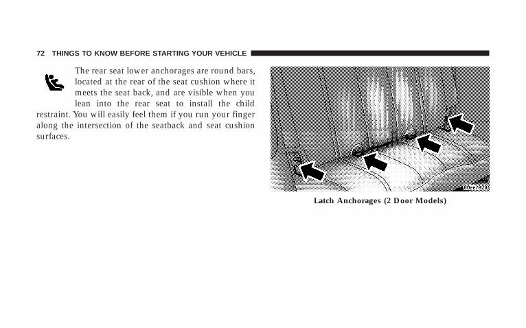
The rear seat lower anchorages are round bars,located at the rear of the seat cushion where itmeets the seat back, and are visible when youlean into the rear seat to install the child
restraint. You will easily feel them if you run your fingeralong the intersection of the seatback and seat cushionsurfaces.
Latch Anchorages (2 Door Models)
72 THINGS TO KNOW BEFORE STARTING YOUR VEHICLE
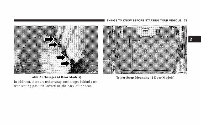
In addition, there are tether strap anchorages behind eachrear seating position located on the back of the seat.
Latch Anchorages (4 Door Models) Tether Strap Mounting (2 Door Models)
THINGS TO KNOW BEFORE STARTING YOUR VEHICLE 73
2
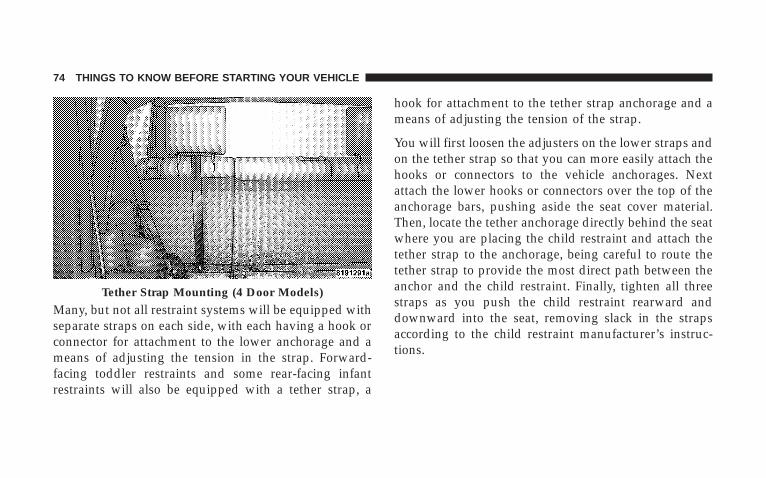
Many, but not all restraint systems will be equipped withseparate straps on each side, with each having a hook orconnector for attachment to the lower anchorage and ameans of adjusting the tension in the strap. Forward-facing toddler restraints and some rear-facing infantrestraints will also be equipped with a tether strap, a
hook for attachment to the tether strap anchorage and ameans of adjusting the tension of the strap.
You will first loosen the adjusters on the lower straps andon the tether strap so that you can more easily attach thehooks or connectors to the vehicle anchorages. Nextattach the lower hooks or connectors over the top of theanchorage bars, pushing aside the seat cover material.Then, locate the tether anchorage directly behind the seatwhere you are placing the child restraint and attach thetether strap to the anchorage, being careful to route thetether strap to provide the most direct path between theanchor and the child restraint. Finally, tighten all threestraps as you push the child restraint rearward anddownward into the seat, removing slack in the strapsaccording to the child restraint manufacturer’s instruc-tions.
Tether Strap Mounting (4 Door Models)
74 THINGS TO KNOW BEFORE STARTING YOUR VEHICLE
WARNING!
Improper installation of a child restraint to theLATCH anchorages can lead to failure of an infant orchild restraint. The child could be badly injured orkilled. Follow the manufacturer’s directions exactlywhen installing an infant or child restraint.
Installing Child Restraints Using the Vehicle SeatBeltThe passenger seat belts are equipped with automaticlocking retractors, which are designed to keep the lapportion tight around the child restraint so that it is notnecessary to use a locking clip. If the seat belt has acinching latch plate, pulling up on the shoulder portionof the lap/shoulder belt will tighten the belt. Any seatbelt system will loosen with time, so check the beltoccasionally and pull it tight if necessary.
If the seat belt has a automatic locking retractor, it willhave a distinctive label. Pull the belt from the retractoruntil there is enough to allow you to pass through thechild restraint and slide the latch plate into the buckle.Then, pull the belt until it is all extracted from theretractor. Allow the belt to return to the retractor, pullingon the excess webbing to tighten the lap portion aboutthe child restraint. Refer to “Automatic Locking Mode”earlier in this section.
In the rear seat, you may have trouble tightening thelap/shoulder belt on the child restraint because thebuckle or latch plate is too close to the belt path openingon the restraint. Disconnect the latch plate from thebuckle and twist the short buckle-end belt several timesto shorten it. Insert the latch plate into the buckle with therelease button facing out.
If the belt still can’t be tightened, or if by pulling andpushing on the restraint loosens the belt, you may need
THINGS TO KNOW BEFORE STARTING YOUR VEHICLE 75
2
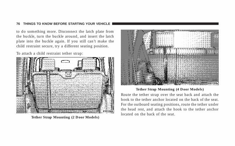
to do something more. Disconnect the latch plate fromthe buckle, turn the buckle around, and insert the latchplate into the buckle again. If you still can’t make thechild restraint secure, try a different seating position.
To attach a child restraint tether strap:
Route the tether strap over the seat back and attach thehook to the tether anchor located on the back of the seat.For the outboard seating positions, route the tether underthe head rest, and attach the hook to the tether anchorlocated on the back of the seat.
Tether Strap Mounting (2 Door Models)
Tether Strap Mounting (4 Door Models)
76 THINGS TO KNOW BEFORE STARTING YOUR VEHICLE
WARNING!
An incorrectly anchored tether strap could lead toincreased head motion and possible injury to thechild. Use only the anchor positions directly behindthe child seat to secure a child restraint top tetherstrap.
Transporting PetsAirbags deploying in the front seat could harm your pet.An unrestrained pet will be thrown about and possiblyinjured, or injure a passenger during panic braking or ina collision.
Pets should be restrained in the rear seat in pet harnessesor pet carriers that are secured by seat belts.
ENGINE BREAK-IN RECOMMENDATIONSA long break-in period is not required for the engine inyour new vehicle.
Drive moderately during the first 300 miles (500 km).After the initial 60 miles (100 km), speeds up to 50 or 55mph (80 or 90 km/h) are desirable.
While cruising, brief full-throttle acceleration, within thelimits of local traffic laws, contributes to a good break-in.Wide open throttle acceleration in low gear can bedetrimental and should be avoided.
The engine oil installed in the engine at the factory is ahigh quality energy conserving type lubricant. Oilchanges should be consistent with anticipated climateconditions under which vehicle operations will occur.The recommended viscosity and quality grades areshown in Section 7 of this manual. NON-DETERGENTOR STRAIGHT MINERAL OILS MUST NEVER BEUSED.
THINGS TO KNOW BEFORE STARTING YOUR VEHICLE 77
2
A new engine may consume some oil during its first fewthousand miles (kilometers) of operation. This should beconsidered as a normal part of the break-in and notinterpreted as an indication of difficulty.
SAFETY TIPS
Exhaust Gas
WARNING!
Exhaust gases can injure or kill. They contain carbonmonoxide (CO) which is colorless and odorless.Breathing it can make you unconscious and caneventually poison you. To avoid breathing (CO)follow the safety tips below.
• Do not inhale exhaust gases. They contain carbonmonoxide, a colorless and odorless gas which can kill.Never run the engine in a closed area, such as agarage, and never sit in a parked vehicle with theengine running for a extended period. If the vehicle isstopped in an open area with engine running for morethan a short period, adjust the ventilation system toforce fresh, outside air into the vehicle.
• Guard against carbon monoxide with proper mainte-nance. Have the exhaust system inspected every timethe vehicle is raised. Have any abnormal conditionsrepaired promptly. Until repaired, drive with all sidewindows fully open.
• Always run the climate control in panel or floor modewhen driving with any windows open, even if onlyslightly, to help keep fresh air circulating inside ve-hicle. Otherwise poisonous gases could be drawn intothe vehicle.
78 THINGS TO KNOW BEFORE STARTING YOUR VEHICLE
• On hardtop models, keep the tailgate window closedwhen driving your vehicle. On fabric top models, donot drive with the rear window curtain up unless theside curtains are also open. This will prevent carbonmonoxide and other poisonous exhaust gases fromentering the vehicle.
Safety Checks You Should Make Inside TheVehicle
Seat BeltsInspect the belt system periodically, checking for cuts,frays and loose parts. Damaged parts must be replacedimmediately. Do not disassemble or modify the system.
Seat belt assemblies must be replaced after an accident ifthey have been damaged (bent retractor, torn webbing,etc.). If there is any question regarding belt or retractorcondition, replace the belt.
Airbag Warning LightThe light should come on and remain on for 6 to 8seconds as a indicator check when the ignition switch isfirst turned on. If the indicator is not lit during starting,have it serviced. If the light stays on or comes on whiledriving, have the system checked by an authorizeddealer.
DefrostersCheck operation by selecting the defrost mode and placethe blower control on high speed. You should feel the airdirected against the windshield.
THINGS TO KNOW BEFORE STARTING YOUR VEHICLE 79
2
Safety Checks You Should Make Outside TheVehicle
TiresExamine tires for excessive tread wear or uneven wearpatterns. Check for stones, nails, glass, or other objectslodged in the tread. Inspect for tread cuts or sidewallcracks. Check wheel nuts for tightness and tires (includ-ing spare) for proper pressure.
LightsHave someone observe the operation of all exterior lightswhile you work the controls. Check turn signal and highbeam indicator lights on the instrument panel.
Fluid LeaksCheck area under vehicle after overnight parking for fuel,coolant, oil, or other fluid leaks. Also, if gasoline fumesare detected, the cause should be located and correctedimmediately.
80 THINGS TO KNOW BEFORE STARTING YOUR VEHICLE
UNDERSTANDING THE FEATURES OF YOUR VEHICLE
CONTENTS
� Mirrors . . . . . . . . . . . . . . . . . . . . . . . . . . . . . . .85
▫ Inside Day/Night Mirror . . . . . . . . . . . . . . . . .85
▫ Outside Mirrors . . . . . . . . . . . . . . . . . . . . . . .86
� Seats . . . . . . . . . . . . . . . . . . . . . . . . . . . . . . . . .87
▫ Front Seat Adjustment . . . . . . . . . . . . . . . . . . .87
▫ Manual Seat Height Adjustment — IfEquipped . . . . . . . . . . . . . . . . . . . . . . . . . . . .88
▫ Front Seat Back Recline . . . . . . . . . . . . . . . . . .88
▫ Front Passenger Easy Entry Seat(2 Door Models) . . . . . . . . . . . . . . . . . . . . . . .89
▫ Head Restraints . . . . . . . . . . . . . . . . . . . . . . .90
▫ Fold And Tumble Rear Seat (2 Door Models) . . .90
▫ Removing The Rear Seat (2 Door Models) . . . . .92
▫ Replacing The Rear Seat (2 Door Models) . . . . .93
▫ 60/40 Split Folding Rear Seat(4 Door Models) . . . . . . . . . . . . . . . . . . . . . . .93
▫ To Raise The Rear Seat . . . . . . . . . . . . . . . . . .95
� To Open And Close The Hood . . . . . . . . . . . . . .96
3
� Lights . . . . . . . . . . . . . . . . . . . . . . . . . . . . . . . .97
▫ Interior Lights . . . . . . . . . . . . . . . . . . . . . . . .97
▫ Multi-Function Control Lever . . . . . . . . . . . . . .98
▫ Parking Lights, Instrument Panel Lights, AndHeadlights . . . . . . . . . . . . . . . . . . . . . . . . . . .99
▫ Lights-On Reminder . . . . . . . . . . . . . . . . . . . 100
▫ Headlight Dimmer Switch . . . . . . . . . . . . . . . 100
▫ Passing Light . . . . . . . . . . . . . . . . . . . . . . . . 100
▫ Front Fog Lights — If Equipped . . . . . . . . . . . 100
▫ Turn Signals . . . . . . . . . . . . . . . . . . . . . . . . . 100
▫ Daytime Running Lights — If Equipped . . . . . 101
� Windshield Wipers And Washers . . . . . . . . . . . . 101
▫ Intermittent Wiper System . . . . . . . . . . . . . . . 101
▫ Windshield Wiper Operation . . . . . . . . . . . . . 102
▫ Windshield Washers . . . . . . . . . . . . . . . . . . . 102
▫ Mist Feature . . . . . . . . . . . . . . . . . . . . . . . . . 102
� Tilt Steering Column . . . . . . . . . . . . . . . . . . . . 103
� Electronic Speed Control — If Equipped . . . . . . 104
▫ To Activate . . . . . . . . . . . . . . . . . . . . . . . . . . 104
▫ To Set At A Desired Speed . . . . . . . . . . . . . . . 105
▫ To Deactivate . . . . . . . . . . . . . . . . . . . . . . . . 105
▫ To Resume Speed . . . . . . . . . . . . . . . . . . . . . 105
▫ To Vary The Speed Setting . . . . . . . . . . . . . . . 105
▫ Manual Transmission . . . . . . . . . . . . . . . . . . 106
▫ To Accelerate For Passing . . . . . . . . . . . . . . . 106
82 UNDERSTANDING THE FEATURES OF YOUR VEHICLE
� Electronic Brake Control System . . . . . . . . . . . . 107
▫ ABS (Anti-Lock Brake System) . . . . . . . . . . . . 107
▫ TCS (Traction Control System) . . . . . . . . . . . . 108
▫ BAS (Brake Assist System) . . . . . . . . . . . . . . . 108
▫ ERM (Electronic Roll Mitigation) . . . . . . . . . . 109
▫ ESP (Electronic Stability Program) . . . . . . . . . 110
▫ ESP/BAS Warning Lamp . . . . . . . . . . . . . . . . 115
� Electrical Power Outlet . . . . . . . . . . . . . . . . . . . 116
▫ Electrical Outlet Use With Engine Off . . . . . . . 117
� Cup Holders . . . . . . . . . . . . . . . . . . . . . . . . . . 117
� Storage . . . . . . . . . . . . . . . . . . . . . . . . . . . . . . 118
▫ Console Storage Compartment . . . . . . . . . . . . 118
▫ Rear Storage Compartment . . . . . . . . . . . . . . 119
� Dual Top — If Equipped . . . . . . . . . . . . . . . . . 120
▫ Removing The Soft Top . . . . . . . . . . . . . . . . . 120
▫ Installing The Soft Top . . . . . . . . . . . . . . . . . 122
� Freedom Top 3– Piece Modular Hard Top . . . . . 125
▫ Front Panel(s) Removal . . . . . . . . . . . . . . . . . 126
▫ Front Panel(s) Installation . . . . . . . . . . . . . . . 128
▫ Front Panel(s) Installation Only(With Rear Hard Top Removed) . . . . . . . . . . . 128
▫ Rear Panel Removal . . . . . . . . . . . . . . . . . . . 129
▫ Rear Panel Installation . . . . . . . . . . . . . . . . . . 131
� Door Frame . . . . . . . . . . . . . . . . . . . . . . . . . . . 132
▫ Door Frame Removal (2 Door Models) . . . . . . 132
▫ Door Frame Installation (2 Door Models) . . . . 134
UNDERSTANDING THE FEATURES OF YOUR VEHICLE 83
3
▫ Door Frame Removal (4 Door Models) . . . . . . 135
▫ Door Frame Installation (4 Door Models) . . . . 138
� Soft Top (2 Door Models) . . . . . . . . . . . . . . . . . 141
▫ Folding Down The Soft Top . . . . . . . . . . . . . . 143
▫ Putting Up The Soft Top . . . . . . . . . . . . . . . . 151
� Sunrider — 4 Door Models . . . . . . . . . . . . . . . . 160
� Soft Top (4 Door Models) . . . . . . . . . . . . . . . . . 164
▫ Folding Down The Soft Top . . . . . . . . . . . . . . 166
▫ Putting Up The Soft Top . . . . . . . . . . . . . . . . 176
� Folding Windshield . . . . . . . . . . . . . . . . . . . . . 187
▫ Lowering The Windshield And RemovingSide Bars . . . . . . . . . . . . . . . . . . . . . . . . . . . 189
▫ Raising The Windshield And Replacing SideBars . . . . . . . . . . . . . . . . . . . . . . . . . . . . . . . 192
� Rear Window Features — Hard Top Only . . . . . 193
▫ Rear Window Wiper/Washer — If Equipped . . 193
▫ Rear Window Defroster — If Equipped . . . . . . 195
84 UNDERSTANDING THE FEATURES OF YOUR VEHICLE
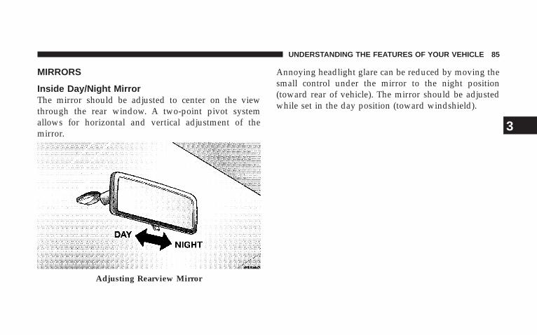
MIRRORS
Inside Day/Night MirrorThe mirror should be adjusted to center on the viewthrough the rear window. A two-point pivot systemallows for horizontal and vertical adjustment of themirror.
Annoying headlight glare can be reduced by moving thesmall control under the mirror to the night position(toward rear of vehicle). The mirror should be adjustedwhile set in the day position (toward windshield).
Adjusting Rearview Mirror
UNDERSTANDING THE FEATURES OF YOUR VEHICLE 85
3
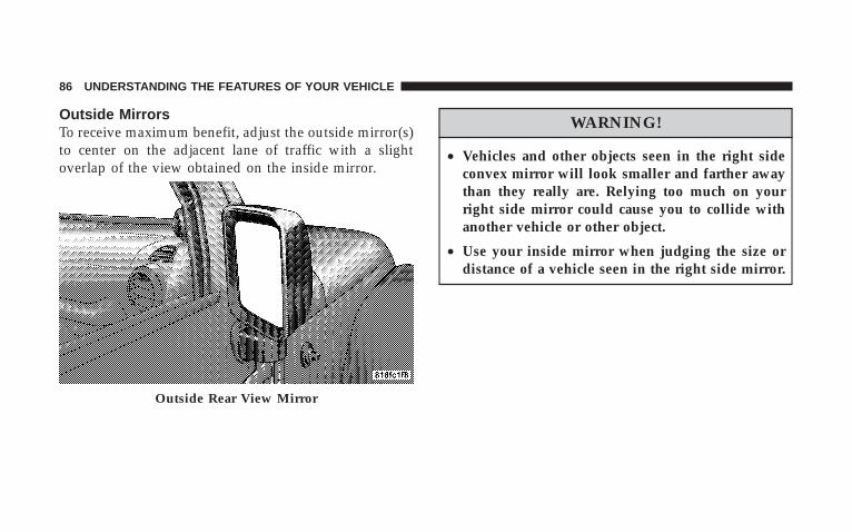
Outside MirrorsTo receive maximum benefit, adjust the outside mirror(s)to center on the adjacent lane of traffic with a slightoverlap of the view obtained on the inside mirror.
WARNING!
• Vehicles and other objects seen in the right sideconvex mirror will look smaller and farther awaythan they really are. Relying too much on yourright side mirror could cause you to collide withanother vehicle or other object.
• Use your inside mirror when judging the size ordistance of a vehicle seen in the right side mirror.
Outside Rear View Mirror
86 UNDERSTANDING THE FEATURES OF YOUR VEHICLE
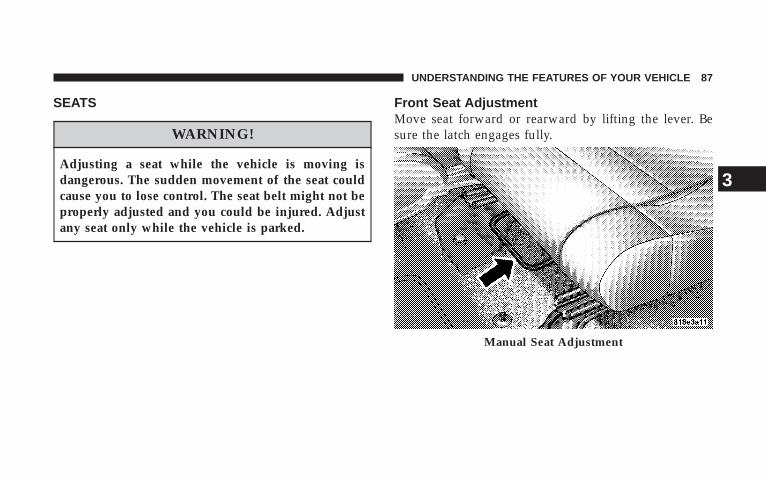
SEATS
WARNING!
Adjusting a seat while the vehicle is moving isdangerous. The sudden movement of the seat couldcause you to lose control. The seat belt might not beproperly adjusted and you could be injured. Adjustany seat only while the vehicle is parked.
Front Seat AdjustmentMove seat forward or rearward by lifting the lever. Besure the latch engages fully.
Manual Seat Adjustment
UNDERSTANDING THE FEATURES OF YOUR VEHICLE 87
3
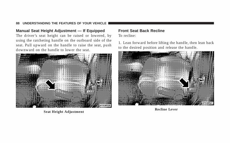
Manual Seat Height Adjustment — If EquippedThe driver’s seat height can be raised or lowered, byusing the ratcheting handle on the outboard side of theseat. Pull upward on the handle to raise the seat, pushdownward on the handle to lower the seat.
Front Seat Back ReclineTo recline:
1. Lean forward before lifting the handle, then lean backto the desired position and release the handle.
Seat Height AdjustmentRecline Lever
88 UNDERSTANDING THE FEATURES OF YOUR VEHICLE
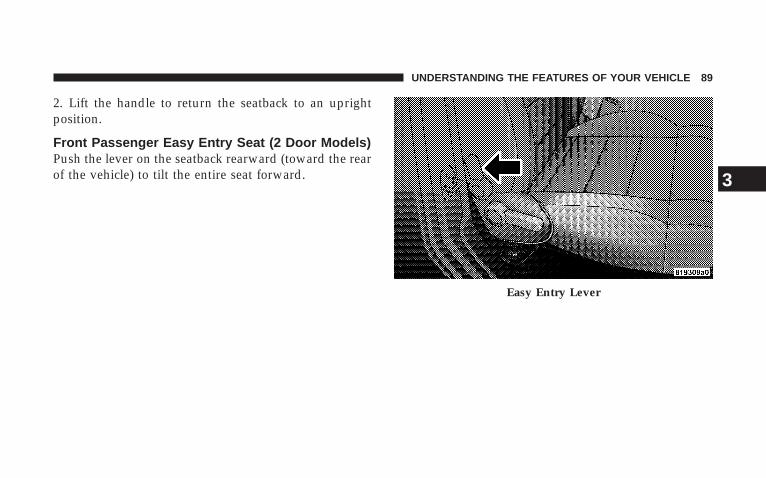
2. Lift the handle to return the seatback to an uprightposition.
Front Passenger Easy Entry Seat (2 Door Models)Push the lever on the seatback rearward (toward the rearof the vehicle) to tilt the entire seat forward.
Easy Entry Lever
UNDERSTANDING THE FEATURES OF YOUR VEHICLE 89
3

Head RestraintsHead restraints can reduce the risk of whiplash injury inthe event of impact from the rear. Adjustable headrestraints should be adjusted so that the upper edge is ashigh as practical. The front head restraints have a lockingbutton that must be pushed inward to lower the headrestraint. The restraints may be raised without pushing inthe button. The rear head restraints are not adjustable.
Fold And Tumble Rear Seat (2 Door Models)
NOTE: Prior to folding the rear seat, it may be necessaryto reposition the front seats.
Adjustable Head Restraints
90 UNDERSTANDING THE FEATURES OF YOUR VEHICLE
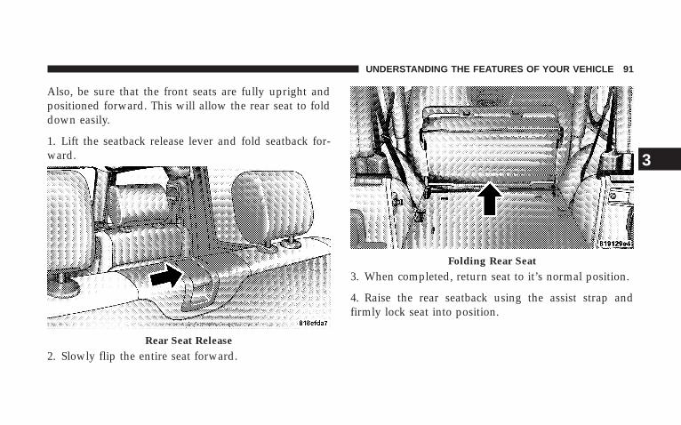
Also, be sure that the front seats are fully upright andpositioned forward. This will allow the rear seat to folddown easily.
1. Lift the seatback release lever and fold seatback for-ward.
2. Slowly flip the entire seat forward.
3. When completed, return seat to it’s normal position.
4. Raise the rear seatback using the assist strap andfirmly lock seat into position.
Rear Seat Release
Folding Rear Seat
UNDERSTANDING THE FEATURES OF YOUR VEHICLE 91
3
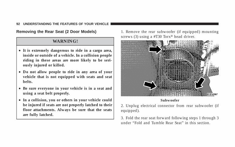
Removing the Rear Seat (2 Door Models)
WARNING!
• It is extremely dangerous to ride in a cargo area,inside or outside of a vehicle. In a collision peopleriding in these areas are more likely to be seri-ously injured or killed.
• Do not allow people to ride in any area of yourvehicle that is not equipped with seats and seatbelts.
• Be sure everyone in your vehicle is in a seat andusing a seat belt properly.
• In a collision, you or others in your vehicle couldbe injured if seats are not properly latched to theirfloor attachments. Always be sure that the seatsare fully latched.
1. Remove the rear subwoofer (if equipped) mountingscrews (3) using a #T30 Torx� head driver.
2. Unplug electrical connector from rear subwoofer (ifequipped).
3. Fold the rear seat forward following steps 1 through 3under “Fold and Tumble Rear Seat” in this section.
Subwoofer
92 UNDERSTANDING THE FEATURES OF YOUR VEHICLE
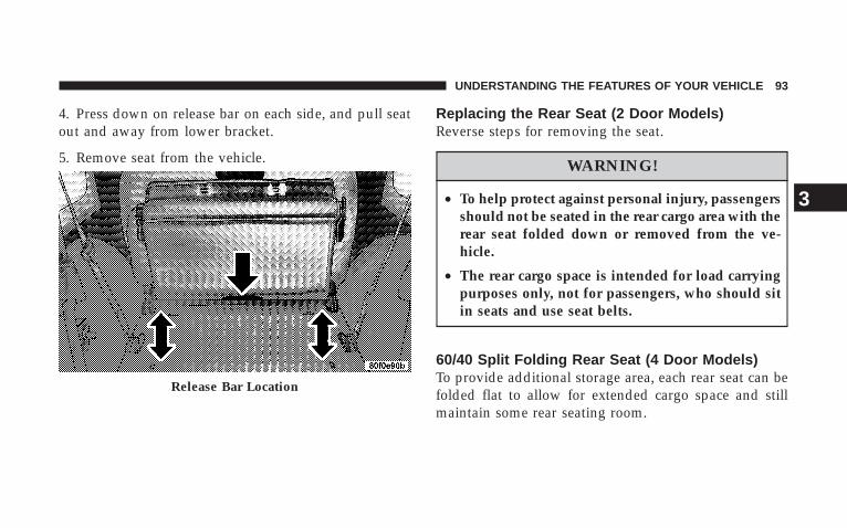
4. Press down on release bar on each side, and pull seatout and away from lower bracket.
5. Remove seat from the vehicle.
Replacing the Rear Seat (2 Door Models)Reverse steps for removing the seat.
WARNING!
• To help protect against personal injury, passengersshould not be seated in the rear cargo area with therear seat folded down or removed from the ve-hicle.
• The rear cargo space is intended for load carryingpurposes only, not for passengers, who should sitin seats and use seat belts.
60/40 Split Folding Rear Seat (4 Door Models)To provide additional storage area, each rear seat can befolded flat to allow for extended cargo space and stillmaintain some rear seating room.
Release Bar Location
UNDERSTANDING THE FEATURES OF YOUR VEHICLE 93
3
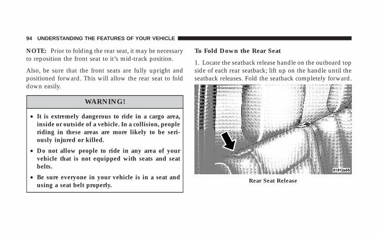
NOTE: Prior to folding the rear seat, it may be necessaryto reposition the front seat to it’s mid-track position.
Also, be sure that the front seats are fully upright andpositioned forward. This will allow the rear seat to folddown easily.
WARNING!
• It is extremely dangerous to ride in a cargo area,inside or outside of a vehicle. In a collision, peopleriding in these areas are more likely to be seri-ously injured or killed.
• Do not allow people to ride in any area of yourvehicle that is not equipped with seats and seatbelts.
• Be sure everyone in your vehicle is in a seat andusing a seat belt properly.
To Fold Down the Rear Seat
1. Locate the seatback release handle on the outboard topside of each rear seatback; lift up on the handle until theseatback releases. Fold the seatback completely forward.
Rear Seat Release
94 UNDERSTANDING THE FEATURES OF YOUR VEHICLE
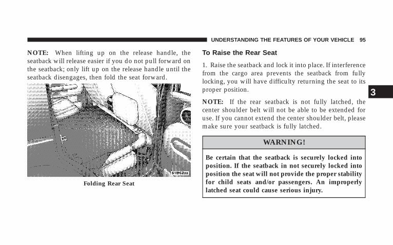
NOTE: When lifting up on the release handle, theseatback will release easier if you do not pull forward onthe seatback; only lift up on the release handle until theseatback disengages, then fold the seat forward.
To Raise the Rear Seat
1. Raise the seatback and lock it into place. If interferencefrom the cargo area prevents the seatback from fullylocking, you will have difficulty returning the seat to itsproper position.
NOTE: If the rear seatback is not fully latched, thecenter shoulder belt will not be able to be extended foruse. If you cannot extend the center shoulder belt, pleasemake sure your seatback is fully latched.
WARNING!
Be certain that the seatback is securely locked intoposition. If the seatback in not securely locked intoposition the seat will not provide the proper stabilityfor child seats and/or passengers. An improperlylatched seat could cause serious injury.
Folding Rear Seat
UNDERSTANDING THE FEATURES OF YOUR VEHICLE 95
3

TO OPEN AND CLOSE THE HOODTo open hood, first release both hood latches.
Next, locate handle in middle of the front end of thehood. Insert hand into gap between hood and top ofgrille, and push handle to the side to raise hood. You may
have to push down slightly on hood before pushing thehandle. Insert the support rod into the slot on the hoodpanel.
To close the hood, remove the support rod from the hoodpanel and place it in the retaining clip. Lower the hoodslowly. Secure both of the hood latches.
WARNING!
If the hood is not fully latched, it could fly up whenthe vehicle is moving and block your forward vision.Be sure all hood latches are latched fully beforedriving.
Hood Latch
96 UNDERSTANDING THE FEATURES OF YOUR VEHICLE
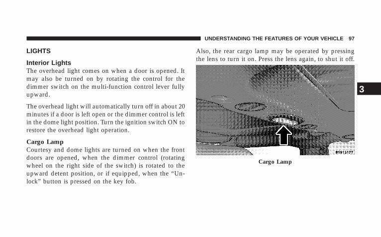
LIGHTS
Interior LightsThe overhead light comes on when a door is opened. Itmay also be turned on by rotating the control for thedimmer switch on the multi-function control lever fullyupward.
The overhead light will automatically turn off in about 20minutes if a door is left open or the dimmer control is leftin the dome light position. Turn the ignition switch ON torestore the overhead light operation.
Cargo LampCourtesy and dome lights are turned on when the frontdoors are opened, when the dimmer control (rotatingwheel on the right side of the switch) is rotated to theupward detent position, or if equipped, when the “Un-lock” button is pressed on the key fob.
Also, the rear cargo lamp may be operated by pressingthe lens to turn it on. Press the lens again, to shut it off.
Cargo Lamp
UNDERSTANDING THE FEATURES OF YOUR VEHICLE 97
3
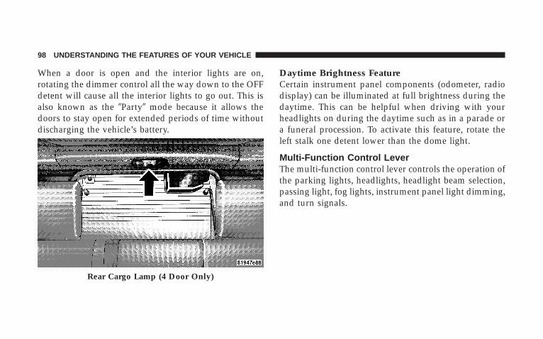
When a door is open and the interior lights are on,rotating the dimmer control all the way down to the OFFdetent will cause all the interior lights to go out. This isalso known as the �Party� mode because it allows thedoors to stay open for extended periods of time withoutdischarging the vehicle’s battery.
Daytime Brightness FeatureCertain instrument panel components (odometer, radiodisplay) can be illuminated at full brightness during thedaytime. This can be helpful when driving with yourheadlights on during the daytime such as in a parade ora funeral procession. To activate this feature, rotate theleft stalk one detent lower than the dome light.
Multi-Function Control LeverThe multi-function control lever controls the operation ofthe parking lights, headlights, headlight beam selection,passing light, fog lights, instrument panel light dimming,and turn signals.
Rear Cargo Lamp (4 Door Only)
98 UNDERSTANDING THE FEATURES OF YOUR VEHICLE
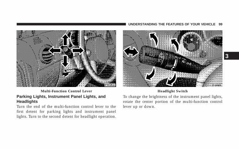
Parking Lights, Instrument Panel Lights, andHeadlightsTurn the end of the multi-function control lever to thefirst detent for parking lights and instrument panellights. Turn to the second detent for headlight operation.
To change the brightness of the instrument panel lights,rotate the center portion of the multi-function controllever up or down.
Multi-Function Control Lever Headlight Switch
UNDERSTANDING THE FEATURES OF YOUR VEHICLE 99
3
NOTE: If the driver’s door is left open, and the head-lights or parking lights are left on, the “High BeamIndicator Light” will flash and a chime will sound.
Lights-On ReminderIf the headlights or parking lights are on after the ignitionis turned off, a chime will sound when the driver’s dooris opened.
Headlight Dimmer SwitchPush the multi-function control lever away from you toswitch the headlights to high beam. Pull the lever to-wards you to switch the headlights back to low beam.
Passing LightYou can signal another vehicle with your headlights bylightly pulling the multi-function control lever towardthe steering wheel. This will cause the headlights to turnon at high beam and remain on until the lever is released.
Front Fog Lights — If EquippedThe front fog light switch is in the multi-functioncontrol lever. To activate the front fog lights, turnon the parking or low beam headlights and pull
out the end of the lever.
NOTE: The fog lights will only operate with the parkinglights or the headlights on low beam. Selecting highbeam headlights will turn off the fog lights.
Turn SignalsMove the multi-function control lever up or down andthe arrows on each side of the instrument cluster flash toshow proper operation of the front and rear turn signallights. You can signal a lane change by moving the leverpartially up or down without moving beyond the detent.
100 UNDERSTANDING THE FEATURES OF YOUR VEHICLE
If either light remains on and does not flash, or there is avery fast flash rate, check for a defective outside lightbulb. If an indicator fails to light when the lever ismoved, it would suggest that the indicator bulb isdefective.
NOTE: A tone will chime if the turn signals are left onfor more than 1 mile (2 km).
Daytime Running Lights — If EquippedThe headlights come on at a low intensity level after thevehicle has been driven approximately 3 feet (1 meter).They will turn off when the vehicle is turned off or whenthe headlights are switched on.
WINDSHIELD WIPERS AND WASHERS
CAUTION!
In cold weather, always turn off the wiper switch andallow the wipers to return to the park position beforeturning off the engine. If the wiper switch is left onand the wipers freeze to the windshield, damage tothe wiper motor may occur when the vehicle isrestarted.
Intermittent Wiper SystemUse the intermittent wiper when weather conditionsmake a single wiping cycle, with a variable pause be-tween cycles, desirable. Move the lever to the DELAYposition, then select the delay interval by turning the endof the lever. The delay can be regulated from a maximumof approximately 18 seconds between cycles, to a cycleevery second.
UNDERSTANDING THE FEATURES OF YOUR VEHICLE 101
3
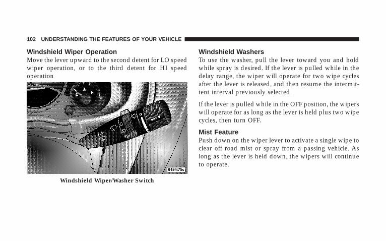
Windshield Wiper OperationMove the lever upward to the second detent for LO speedwiper operation, or to the third detent for HI speedoperation
Windshield WashersTo use the washer, pull the lever toward you and holdwhile spray is desired. If the lever is pulled while in thedelay range, the wiper will operate for two wipe cyclesafter the lever is released, and then resume the intermit-tent interval previously selected.
If the lever is pulled while in the OFF position, the wiperswill operate for as long as the lever is held plus two wipecycles, then turn OFF.
Mist FeaturePush down on the wiper lever to activate a single wipe toclear off road mist or spray from a passing vehicle. Aslong as the lever is held down, the wipers will continueto operate.
Windshield Wiper/Washer Switch
102 UNDERSTANDING THE FEATURES OF YOUR VEHICLE
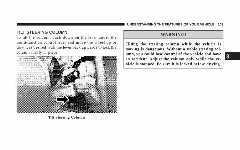
TILT STEERING COLUMNTo tilt the column, push down on the lever under themulti-function control lever and move the wheel up ordown, as desired. Pull the lever back upwards to lock thecolumn firmly in place.
WARNING!
Tilting the steering column while the vehicle ismoving is dangerous. Without a stable steering col-umn, you could lose control of the vehicle and havean accident. Adjust the column only while the ve-hicle is stopped. Be sure it is locked before driving.
Tilt Steering Column
UNDERSTANDING THE FEATURES OF YOUR VEHICLE 103
3
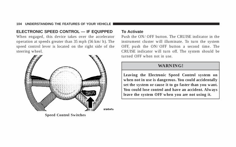
ELECTRONIC SPEED CONTROL — IF EQUIPPEDWhen engaged, this device takes over the acceleratoroperation at speeds greater than 35 mph (56 km/h). Thespeed control lever is located on the right side of thesteering wheel.
To ActivatePush the ON/OFF button. The CRUISE indicator in theinstrument cluster will illuminate. To turn the systemOFF, push the ON/OFF button a second time. TheCRUISE indicator will turn off. The system should beturned OFF when not in use.
WARNING!
Leaving the Electronic Speed Control system onwhen not in use is dangerous. You could accidentallyset the system or cause it to go faster than you want.You could lose control and have an accident. Alwaysleave the system OFF when you are not using it.
Speed Control Switches
104 UNDERSTANDING THE FEATURES OF YOUR VEHICLE

To Set At A Desired SpeedWhen the vehicle has reached the desired speed, pressdown on the lever and release. Release the acceleratorand the vehicle will operate at the selected speed.
NOTE: The vehicle should be traveling at a steadyspeed and on level ground before pressing the SET lever.
To DeactivateA soft tap on the brake pedal, pulling the speed controllever towards you “CANCEL”, or normal brake or clutchpressure while slowing the vehicle will deactivate speedcontrol without erasing the set speed memory. Pressingthe ON/OFF button or turning off the ignition switcherases the set speed memory.
To Resume SpeedTo resume a previously set speed, push the “RESUMEACCEL” lever up and release. Resume can be used at anyspeed above 20 mph (32 km/h).
To Vary The Speed SettingWhen the speed control is ON, speed can be increased bypushing up and holding “RESUME ACCEL”. Release thelever when the desired speed is reached, and the newspeed will be set.
Tapping “RESUME ACCEL” once will result in a 2 mph(3 km/h) speed increase. Each time the lever is tapped,speed increases so that tapping the lever three times willincrease speed by 6 mph (10 km/h), etc.
UNDERSTANDING THE FEATURES OF YOUR VEHICLE 105
3
To decrease speed while speed control is ON, push downand hold “SET DECEL”. Release the lever when thedesired speed is reached, and the new speed will be set.
Tapping the “SET DECEL” button once will result in a 1mph (2 km/h) speed decrease. Each time the button istapped, speed decreases.
Manual TransmissionDepressing the clutch pedal will disengage the speedcontrol. A slight increase in engine RPM before the speedcontrol disengages is normal.
Vehicles equipped with manual transmissions may needto be shifted into a lower gear to climb hills withoutspeed loss.
WARNING!
Speed Control can be dangerous where the systemcan’t maintain a constant speed. Your vehicle couldgo too fast for the conditions, and you could losecontrol. An accident could be the result. Don’t useSpeed Control in heavy traffic or on roads that arewinding, icy, snow-covered, or slippery.
To Accelerate For PassingDepress the accelerator as you would normally. When thepedal is released, the vehicle will return to the set speed.
Using Speed Control On Hills
NOTE: The speed control system maintains speed upand down hills. A slight speed change on moderate hillsis normal.
106 UNDERSTANDING THE FEATURES OF YOUR VEHICLE
On steep hills, a greater speed loss or gain and/or morefrequent downshifts (auto transmission only) may occurso it may be preferable to drive without speed control.
ELECTRONIC BRAKE CONTROL SYSTEMYour vehicle is equipped with an advanced electronicbrake control system that includes ABS (Anti-Lock BrakeSystem), TCS (Traction Control System), BAS (BrakeAssist System), ERM (Electronic Roll Mitigation), andESP (Electronic Stability Program). All five systems worktogether to enhance vehicle stability and control in vari-ous driving conditions, and are commonly referred to asESP.
ABS (Anti-Lock Brake System)
This system aids the driver in maintaining vehicle controlunder adverse braking conditions. The system controlshydraulic brake pressure to prevent wheel lock-up and
help avoid skidding on slippery surfaces during braking.Refer to “Anti-Lock Brake System” in Section 5 of thismanual for more information about ABS.
WARNING!
ABS (Anti-Lock Brake System) cannot prevent thenatural laws of physics from acting on the vehicle,nor can it increase the traction afforded by prevailingroad conditions. ABS cannot prevent accidents, in-cluding those resulting from excessive speed inturns, driving on very slippery surfaces, or hydro-planing. Only a safe, attentive, and skillful driver canprevent accidents. The capabilities of an ABS-equipped vehicle must never be exploited in a reck-less or dangerous manner which could jeopardize theuser’s safety or the safety of others.
UNDERSTANDING THE FEATURES OF YOUR VEHICLE 107
3
TCS (Traction Control System)
This system monitors the amount of wheel spin of each ofthe driven wheels. If wheel spin is detected, brakepressure is applied to the slipping wheel(s) to provideenhanced acceleration and stability. A feature of the TCSsystem functions similar to a limited slip differential andcontrols the wheel spin across a driven axle. If one wheelon a driven axle is spinning faster than the other, thesystem will apply the brake of the spinning wheel. Thiswill allow more engine torque to be applied to the wheelthat is not spinning. This feature remains active even ifTCS and ESP are in either the “Partial Off” or “Full Off”modes. Refer to “ESP (Electronic Stability Program)” inthis section.
BAS (Brake Assist System)The BAS is designed to optimize the vehicle’s brakingcapability during emergency braking maneuvers. Thesystem detects an emergency braking situation by sens-ing the rate and amount of brake application and thenapplies optimum pressure to the brakes. This can helpreduce braking distances. The BAS complements theanti-lock brake system (ABS). Applying the brakes veryquickly results in the best BAS assistance. To receive thebenefit of the system, you must apply continuous brak-ing pressure during the stopping sequence. Do notreduce brake pedal pressure unless braking is no longerdesired. Once the brake pedal is released, the BAS isdeactivated.
108 UNDERSTANDING THE FEATURES OF YOUR VEHICLE
WARNING!
BAS (Brake Assist System) cannot prevent the natu-ral laws of physics from acting on the vehicle, nor canit increase the traction afforded by prevailing roadconditions. BAS cannot prevent accidents, includingthose resulting from excessive speed in turns, drivingon very slippery surfaces, or hydroplaning. Only asafe, attentive, and skillful driver can prevent acci-dents. The capabilities of a BAS-equipped vehiclemust never be exploited in a reckless or dangerousmanner which could jeopardize the user’s safety orthe safety of others.
ERM (Electronic Roll Mitigation)This system anticipates the potential for wheel lift bymonitoring the driver’s steering wheel input and thespeed of the vehicle. When ERM determines that the rateof change of the steering wheel angle and vehicles speedare sufficient to potentially cause wheel lift, it applies theappropriate brake and may reduce engine power tolessen the chance that wheel lift will occur. ERM will onlyintervene during very severe or evasive driving maneu-vers.
ERM can only reduce the chance of wheel lift occurringduring severe or evasive driving maneuvers. It cannotprevent wheel lift due to other factors such as roadconditions, leaving the roadway or striking objects orother vehicles.
UNDERSTANDING THE FEATURES OF YOUR VEHICLE 109
3
NOTE: Anytime the ESP system is in the “Full Off”mode, ERM is disabled. Refer to ESP (Electronic StabilityProgram) for a complete explanation of the available ESPmodes.
WARNING!
Many factors, such as vehicle loading, road condi-tions and driving conditions, influence the chancethat wheel lift or rollover may occur. ERM cannotprevent all wheel lift or rollovers, especially thosethat involve leaving the roadway or striking objectsor other vehicles. Only a safe, attentive, and skillfuldriver can prevent accidents. The capabilities of anERM-equipped vehicle must never be exploited in areckless or dangerous manner which could jeopar-dize the user’s safety or the safety of others.
ESP (Electronic Stability Program)
This system enhances directional control and stability ofthe vehicle under various driving conditions. ESP cor-rects for over/under steering of the vehicle by applyingthe brake of the appropriate wheel to assist in counter-acting the over/under steer condition. Engine powermay also be reduced to help the vehicle maintain thedesired path.
ESP uses sensors in the vehicle to determine the vehiclepath intended by the driver and compares it to the actualpath of the vehicle. When the actual path does not matchthe intended path, ESP applies the brake of the appropri-ate wheel to assist in counteracting the oversteer orundersteer condition.
• Oversteer - when the vehicle is turning more thanappropriate for the steering wheel position.
110 UNDERSTANDING THE FEATURES OF YOUR VEHICLE
• Understeer - when the vehicle is turning less thanappropriate for the steering wheel position.
The �ESP/TCS Indicator Light� located in the instrumentcluster, starts to flash as soon as the tires lose traction andthe ESP system becomes active. The �ESP/TCS IndicatorLight� also flashes when TCS is active. If the �ESP/TCSIndicator Light� begins to flash during acceleration, easeup on the accelerator and apply as little throttle aspossible. Be sure to adapt your speed and driving to theprevailing road conditions.
WARNING!
ESP (Electronic Stability Program) cannot prevent thenatural laws of physics from acting on the vehicle,nor can it increase the traction afforded by prevailingroad conditions. ESP cannot prevent accidents, in-cluding those resulting from excessive speed inturns, driving on very slippery surfaces, or hydro-planing. Only a safe, attentive, and skillful driver canprevent accidents. The capabilities of an ESP-equipped vehicle must never be exploited in a reck-less or dangerous manner which could jeopardize theuser’s safety or the safety of others.
The ESP system has 3 available operating modes in 4WDHigh Range. The system has 1 operating mode in 4WDLow Range. 2WD vehicles and 4WD vehicles in 2WDmode have 2 operating modes.
UNDERSTANDING THE FEATURES OF YOUR VEHICLE 111
3
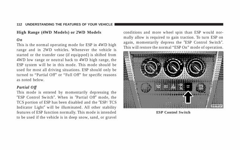
High Range (4WD Models) or 2WD Models
OnThis is the normal operating mode for ESP in 4WD highrange and in 2WD vehicles. Whenever the vehicle isstarted or the transfer case (if equipped) is shifted from4WD low range or neutral back to 4WD high range, theESP system will be in this mode. This mode should beused for most all driving situations. ESP should only beturned to “Partial Off” or “Full Off” for specific reasonsas noted below.
Partial OffThis mode is entered by momentarily depressing the�ESP Control Switch�. When in �Partial Off� mode, theTCS portion of ESP has been disabled and the �ESP/TCSIndicator Light� will be illuminated. All other stabilityfeatures of ESP function normally. This mode is intendedto be used if the vehicle is in deep snow, sand, or gravel
conditions and more wheel spin than ESP would nor-mally allow is required to gain traction. To turn ESP onagain, momentarily depress the �ESP Control Switch�.This will restore the normal “ESP On” mode of operation.
ESP Control Switch
112 UNDERSTANDING THE FEATURES OF YOUR VEHICLE
NOTE: To improve the vehicle’s traction when drivingwith snow chains, or starting off in deep snow, sand, orgravel, it may be desirable to switch to the “Partial Off”mode by pressing the ESP switch. Once the situationrequiring ESP to be switched to the “Partial Off” mode isovercome, turn ESP back on by momentarily depressingthe “ESP Control Switch”. This may be done while thevehicle is in motion.
ESP Off (4WD High Range Only)This mode is intended for off-highway or off-road usewhen ESP stability features could inhibit vehicle maneu-verability due to trail conditions. This mode is entered bydepressing and holding the “ESP Control Switch” for 5seconds when the vehicle is stopped and the engine isrunning. In this mode, all ESP and TCS stability featuresare turned off except for the “limited slip” feature de-scribed in the TCS section. After 5 seconds, a chime will
sound, the �ESP/TCS Indicator Light� will illuminate,and the �ESP OFF� message will appear in the odometer.Refer to “Compass and Mini-Trip Computer — IfEquipped” in Section 4 of this manual. To turn ESP onagain, momentarily depress the �ESP Control Switch�.This will restore the normal “ESP On” mode of operation.
NOTE: The ESP system will change to “Partial Off”mode if the vehicle speed exceeds 40 mph (64 km/h).After the vehicle speed is reduced below 35 mph (56km/h), the ESP system will return to “Full Off” mode.
NOTE: The “ESP OFF” message will display and theaudible chime will sound when the gear selector isplaced into the “P” (Park) position from any positionother than “P” (Park), and then moved out of the “P”(Park) position. This will occur even if the message waspreviously cleared.
UNDERSTANDING THE FEATURES OF YOUR VEHICLE 113
3
WARNING!
With the ESP switched off, the enhanced vehiclestability offered by ESP and ERM are unavailable. Inan emergency evasive maneuver, the ESP and ERMsystems will not engage to assist in maintainingstability. The “Full Off” ESP mode is intended foroff-highway or off-road use only.
4WD Low Range
ESP OffThis is the normal operating mode for ESP in 4WD lowrange. Whenever the vehicle is started in 4WD low range,or the transfer case (if equipped) is shifted from 4WDhigh range or neutral to 4WD low range, the ESP systemwill be in this mode. In 4WD low range, ESP and TCS,
except for the “limited slip” feature described in the TCSsection, are turned off until the vehicle reaches a speed of40 mph (48 km/h). At 40 mph (48 km/h), the normal ESPstability function returns but TCS remains off. When thevehicle speed drops below 35 mph (40 km/h), the ESPsystem shuts off. ESP is off at low vehicle speeds in 4WDlow range so that it will not interfere with off-roaddriving but ESP function returns to provide the stabilityfeature at speeds above 40 mph (48 km/h). The �ESP/TCS Indicator Light� will always be illuminated in 4WDlow range when ESP is off.
NOTE: The “ESP OFF” message will display and theaudible chime will sound when the gear selector isplaced into the “P” (Park) position from any positionother than “P” (Park), and then moved out of the “P”(Park) position. This will occur even if the message waspreviously cleared.
114 UNDERSTANDING THE FEATURES OF YOUR VEHICLE
WARNING!
With the ESP switched off, the enhanced vehiclestability offered by ESP and ERM are unavailable. Inan emergency evasive maneuver, the ESP and ERMsystems will not engage to assist in maintainingstability. The “Full Off” mode is intended for off-highway or off-road use only.
ESP/BAS Warning LampThe malfunction indicator lamp for the ESP iscombined with the BAS indicator. The yellow“ESP/BAS Warning Lamp” in the instrumentcluster comes on when the ignition switch is
turned to the “ON” position. It should go out with theengine running.
If the “ESP/BAS Warning Lamp” comes on continuouslywith the engine running, a malfunction has been detectedin either the ESP or the BAS system, or both. If this lightremains on after several ignition cycles, and the vehiclehas been driven several miles at speeds greater than 30mph (48 km/h), see your authorized dealer as soon aspossible to have the problem diagnosed and corrected.
NOTE:• �The �ESP/BAS Warning Lamp� comes on momen-
tarily each time the ignition switch is turned ON.
• Each time the ignition is turned ON, the ESP Systemwill be ON even if it was turned off previously.
• The ESP Control System will make buzzing or clickingsounds when it is active. This is normal; the soundswill stop when ESP becomes inactive following themaneuver that caused the ESP activation.
UNDERSTANDING THE FEATURES OF YOUR VEHICLE 115
3
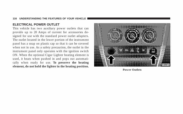
ELECTRICAL POWER OUTLETThis vehicle has two auxiliary power outlets that canprovide up to 20 Amps of current for accessories de-signed for use with the standard power outlet adapters.The outlet located in the lower portion of the instrumentpanel has a snap on plastic cap so that it can be coveredwhen not in use. As a safety precaution, the outlet in theinstrument panel only operates with the ignition switchON. When the optional Cigar Lighter heating element isused, it heats when pushed in and pops out automati-cally when ready for use. To preserve the heatingelement, do not hold the lighter in the heating position.
Power Outlets
116 UNDERSTANDING THE FEATURES OF YOUR VEHICLE
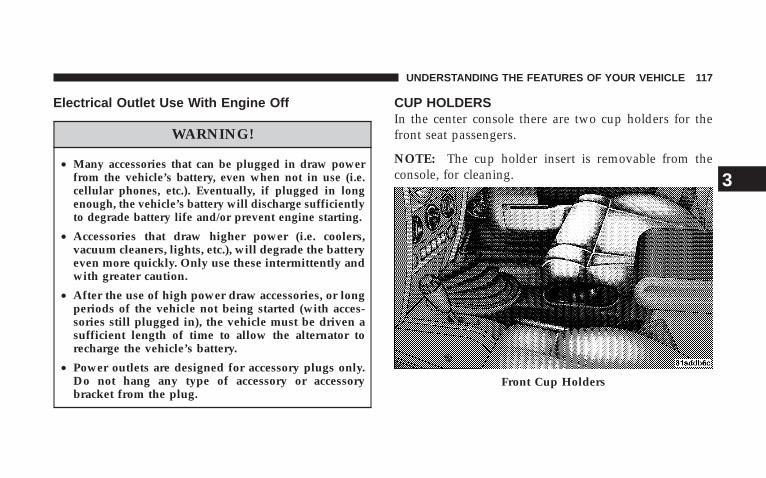
Electrical Outlet Use With Engine Off
WARNING!
• Many accessories that can be plugged in draw powerfrom the vehicle’s battery, even when not in use (i.e.cellular phones, etc.). Eventually, if plugged in longenough, the vehicle’s battery will discharge sufficientlyto degrade battery life and/or prevent engine starting.
• Accessories that draw higher power (i.e. coolers,vacuum cleaners, lights, etc.), will degrade the batteryeven more quickly. Only use these intermittently andwith greater caution.
• After the use of high power draw accessories, or longperiods of the vehicle not being started (with acces-sories still plugged in), the vehicle must be driven asufficient length of time to allow the alternator torecharge the vehicle’s battery.
• Power outlets are designed for accessory plugs only.Do not hang any type of accessory or accessorybracket from the plug.
CUP HOLDERSIn the center console there are two cup holders for thefront seat passengers.
NOTE: The cup holder insert is removable from theconsole, for cleaning.
Front Cup Holders
UNDERSTANDING THE FEATURES OF YOUR VEHICLE 117
3
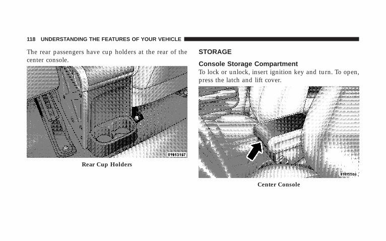
The rear passengers have cup holders at the rear of thecenter console.
STORAGE
Console Storage CompartmentTo lock or unlock, insert ignition key and turn. To open,press the latch and lift cover.
Rear Cup Holders
Center Console
118 UNDERSTANDING THE FEATURES OF YOUR VEHICLE
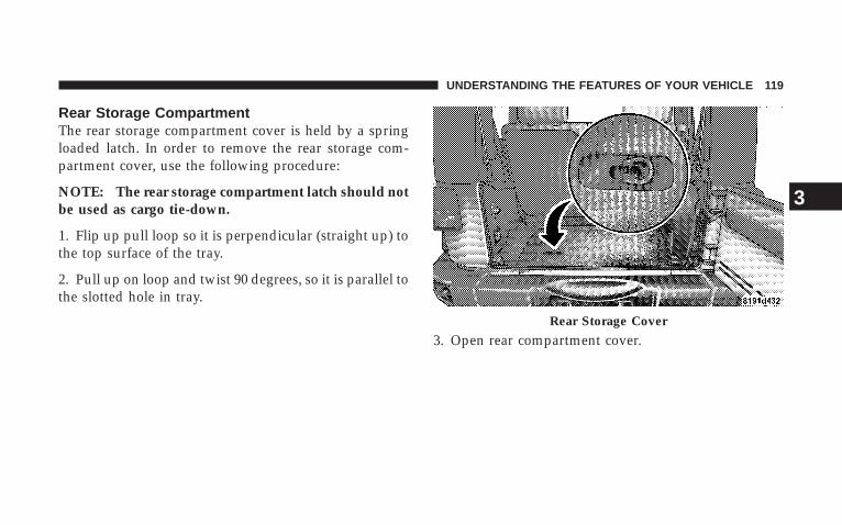
Rear Storage CompartmentThe rear storage compartment cover is held by a springloaded latch. In order to remove the rear storage com-partment cover, use the following procedure:
NOTE: The rear storage compartment latch should notbe used as cargo tie-down.
1. Flip up pull loop so it is perpendicular (straight up) tothe top surface of the tray.
2. Pull up on loop and twist 90 degrees, so it is parallel tothe slotted hole in tray.
3. Open rear compartment cover.Rear Storage Cover
UNDERSTANDING THE FEATURES OF YOUR VEHICLE 119
3
DUAL TOP — IF EQUIPPEDIf your vehicle is equipped with a Dual Top, you mustremove one of the tops from the vehicle. If the soft topis removed, the pivot brackets must also be removedfrom the sport bar. The soft top was installed at thefactory for shipping purposes only. The soft top and thehard top are to be used independently. Removal ismandatory to prevent any possible wear and tear on thesoft top. Your vehicle warranty will not cover damageresulting from both tops remaining on the vehicle at thesame time for extended periods of time.
Removing The Soft Top
1. Locate and remove the 2 boxes that contain thefollowing items:
• Right and left door frames
• Door frame attachment knobs (4 for 2 door models,6 for 4 door models)
• Right and left quarter windows
• Rear window
• Rear window roll up straps (2)
• Sunrider secure straps (2) (If Equipped)
• Rear swing gate brackets (2)
2. Remove the hard top. Refer to “Freedom Top 3 – PieceModular Hard Top — Front/Rear Panel Removal” laterin this section.
120 UNDERSTANDING THE FEATURES OF YOUR VEHICLE
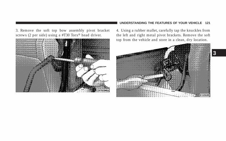
3. Remove the soft top bow assembly pivot bracketscrews (2 per side) using a #T30 Torx� head driver.
4. Using a rubber mallet, carefully tap the knuckles fromthe left and right metal pivot brackets. Remove the softtop from the vehicle and store in a clean, dry location.
UNDERSTANDING THE FEATURES OF YOUR VEHICLE 121
3
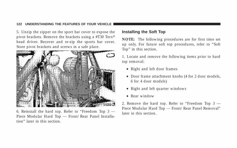
5. Unzip the zipper on the sport bar cover to expose thepivot brackets. Remove the brackets using a #T30 Torx�head driver. Recover and re-zip the sports bar cover.Store pivot brackets and screws in a safe place.
6. Reinstall the hard top. Refer to “Freedom Top 3 —Piece Modular Hard Top — Front/Rear Panel Installa-tion” later in this section.
Installing the Soft Top
NOTE: The following procedures are for first time setup only. For future soft top procedures, refer to “SoftTop” in this section.
1. Locate and remove the following items prior to hardtop removal:
• Right and left door frames
• Door frame attachment knobs (4 for 2 door models,6 for 4 door models)
• Right and left quarter windows
• Rear window
2. Remove the hard top. Refer to “Freedom Top 3 —Piece Modular Hard Top — Front/Rear Panel Removal”later in this section.
122 UNDERSTANDING THE FEATURES OF YOUR VEHICLE
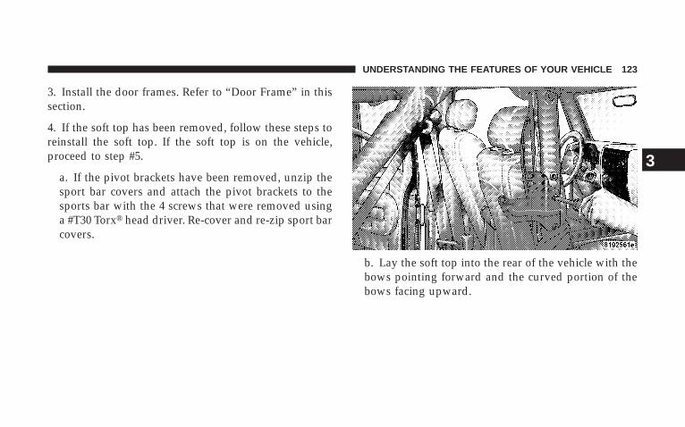
3. Install the door frames. Refer to “Door Frame” in thissection.
4. If the soft top has been removed, follow these steps toreinstall the soft top. If the soft top is on the vehicle,proceed to step #5.
a. If the pivot brackets have been removed, unzip thesport bar covers and attach the pivot brackets to thesports bar with the 4 screws that were removed usinga #T30 Torx� head driver. Re-cover and re-zip sport barcovers.
b. Lay the soft top into the rear of the vehicle with thebows pointing forward and the curved portion of thebows facing upward.
UNDERSTANDING THE FEATURES OF YOUR VEHICLE 123
3

c. Tap the knuckles on the side with a rubber mallet toreattach them to the metal pivot brackets.
d. Screw the pivot screws back into place using a #T30Torx� head driver. Secure them until they are snugbeing careful not to cross-thread the screws or overtighten.
CAUTION!
Do not overtighten the screws. You can strip thescrews if they are overtightened.
124 UNDERSTANDING THE FEATURES OF YOUR VEHICLE
5. Unsnap and remove the black boot cover. This covershould be discarded. It was intended as a protectivecover for shipping only.
NOTE: A visual instruction sheet is enclosed in the dualtop wrap.
6. Remove the swing gate bar (black metal bar forbottom of rear window) located in the soft top and setaside.
NOTE: Be sure the wire harness in the right rear corneris not tangled in the soft top bows before you lift the top.
7. Put up the soft top. Refer to “Soft Top — Putting Upthe Soft Top” in this section.
FREEDOM TOP 3– PIECE MODULAR HARD TOP
CAUTION!
• The hard top is not designed to carry any addi-tional loads such as roof racks, spare tires, build-ing, hunting, or camping supplies, and/or luggage,etc. Also, it was not designed as a structuralmember of the vehicle, and thus cannot properlycarry any additional loads other than environmen-tal (rain, snow, etc.).
CAUTION!
Do not move your vehicle until the top has beeneither fully attached to the windshield frame andbodyside, or fully removed.
UNDERSTANDING THE FEATURES OF YOUR VEHICLE 125
3
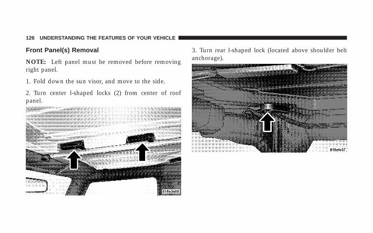
Front Panel(s) Removal
NOTE: Left panel must be removed before removingright panel.
1. Fold down the sun visor, and move to the side.
2. Turn center l-shaped locks (2) from center of roofpanel.
3. Turn rear l-shaped lock (located above shoulder beltanchorage).
126 UNDERSTANDING THE FEATURES OF YOUR VEHICLE
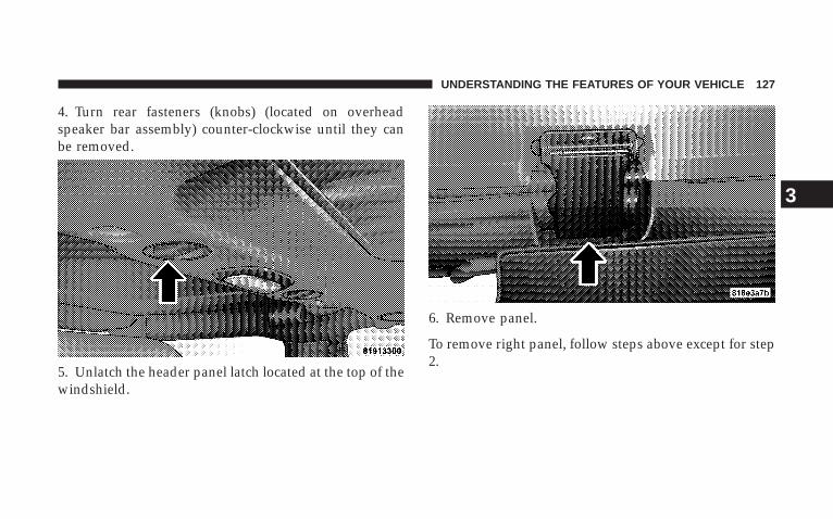
4. Turn rear fasteners (knobs) (located on overheadspeaker bar assembly) counter-clockwise until they canbe removed.
5. Unlatch the header panel latch located at the top of thewindshield.
6. Remove panel.
To remove right panel, follow steps above except for step2.
UNDERSTANDING THE FEATURES OF YOUR VEHICLE 127
3
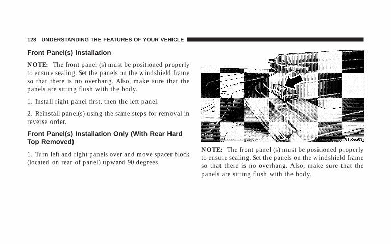
Front Panel(s) Installation
NOTE: The front panel (s) must be positioned properlyto ensure sealing. Set the panels on the windshield frameso that there is no overhang. Also, make sure that thepanels are sitting flush with the body.
1. Install right panel first, then the left panel.
2. Reinstall panel(s) using the same steps for removal inreverse order.
Front Panel(s) Installation Only (With Rear HardTop Removed)
1. Turn left and right panels over and move spacer block(located on rear of panel) upward 90 degrees.
NOTE: The front panel (s) must be positioned properlyto ensure sealing. Set the panels on the windshield frameso that there is no overhang. Also, make sure that thepanels are sitting flush with the body.
128 UNDERSTANDING THE FEATURES OF YOUR VEHICLE

2. Install right panel first, then the left panel.
3. Reinstall panel(s) using the same steps for removal inreverse order.
Rear Panel Removal
1. Remove both front panels. Refer to “Front Panel(s)Removal” in this section.
2. Open both doors.
3. Remove the two (2) Torx� head screws which securethe hard top at the B-pillar (near top of door) using a #40Torx� head driver (4 Door Only).
4. Remove the six (6) Torx� head screws which secure thehard top to the vehicle (along the interior bodyside) usinga #40 Torx� head driver.
5. Open swing gate all the way to ensure clearance of therear window glass. Lift rear window glass.
UNDERSTANDING THE FEATURES OF YOUR VEHICLE 129
3
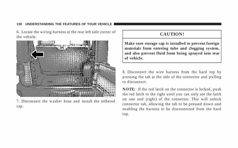
6. Locate the wiring harness at the rear left side corner ofthe vehicle.
7. Disconnect the washer hose and install the tetheredcap.
CAUTION!
Make sure storage cap is installed to prevent foreignmaterials from entering tube and clogging system,and also prevent fluid from being sprayed into rearof vehicle.
8. Disconnect the wire harness from the hard top bypressing the tab at the side of the connector and pullingto disconnect.
NOTE: If the red latch on the connector is locked, pushthe red latch to the right until you can only see the latchon one end (right) of the connector. This will unlockconnector tab, allowing the tab to be pressed down andenabling the harness to be disconnected from the hardtop.
130 UNDERSTANDING THE FEATURES OF YOUR VEHICLE
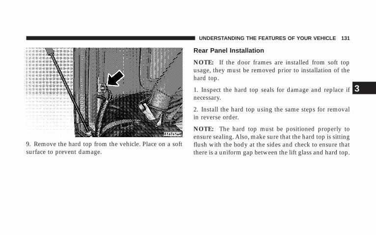
9. Remove the hard top from the vehicle. Place on a softsurface to prevent damage.
Rear Panel Installation
NOTE: If the door frames are installed from soft topusage, they must be removed prior to installation of thehard top.
1. Inspect the hard top seals for damage and replace ifnecessary.
2. Install the hard top using the same steps for removalin reverse order.
NOTE: The hard top must be positioned properly toensure sealing. Also, make sure that the hard top is sittingflush with the body at the sides and check to ensure thatthere is a uniform gap between the lift glass and hard top.
UNDERSTANDING THE FEATURES OF YOUR VEHICLE 131
3
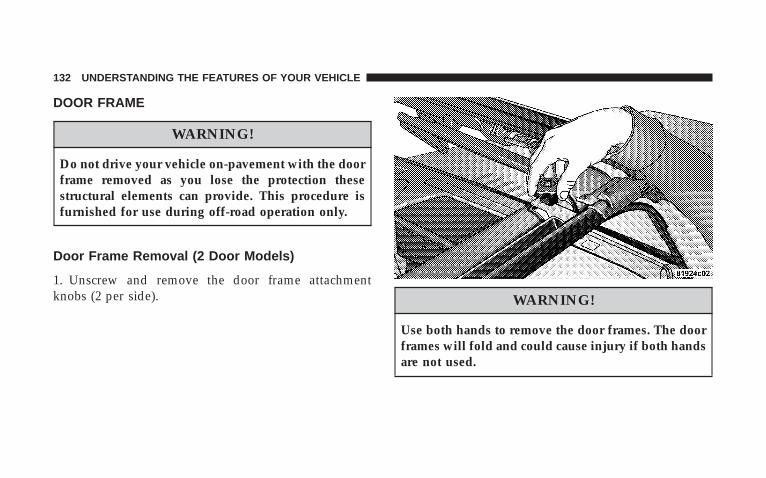
DOOR FRAME
WARNING!
Do not drive your vehicle on-pavement with the doorframe removed as you lose the protection thesestructural elements can provide. This procedure isfurnished for use during off-road operation only.
Door Frame Removal (2 Door Models)
1. Unscrew and remove the door frame attachmentknobs (2 per side). WARNING!
Use both hands to remove the door frames. The doorframes will fold and could cause injury if both handsare not used.
132 UNDERSTANDING THE FEATURES OF YOUR VEHICLE
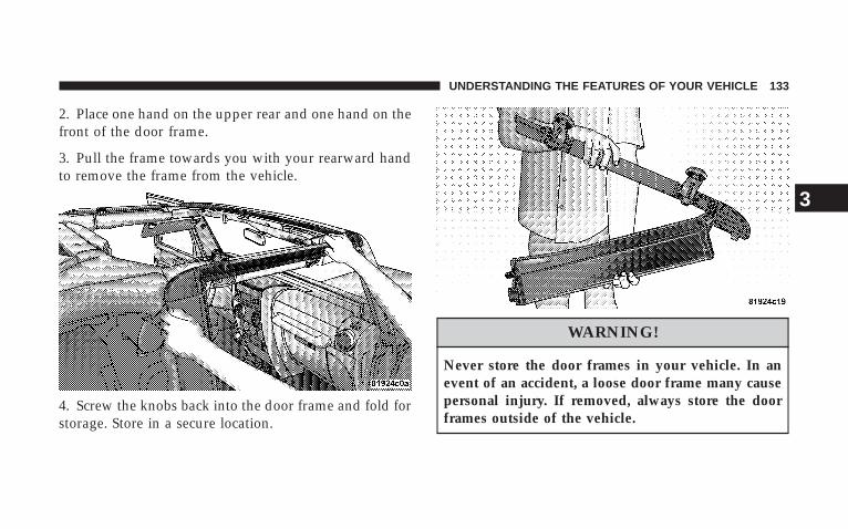
2. Place one hand on the upper rear and one hand on thefront of the door frame.
3. Pull the frame towards you with your rearward handto remove the frame from the vehicle.
4. Screw the knobs back into the door frame and fold forstorage. Store in a secure location.
WARNING!
Never store the door frames in your vehicle. In anevent of an accident, a loose door frame many causepersonal injury. If removed, always store the doorframes outside of the vehicle.
UNDERSTANDING THE FEATURES OF YOUR VEHICLE 133
3
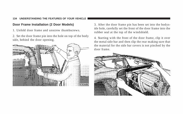
Door Frame Installation (2 Door Models)
1. Unfold door frame and unscrew thumbscrews.
2. Set the door frame pin into the hole on top of the bodyside, behind the door opening.
3. After the door frame pin has been set into the bodys-ide hole, carefully set the front of the door frame into therubber seal at the top of the windshield.
4. Starting with the front of the door frame, clip it overthe metal side bar and then clip the rear making sure thatthe material for the side bar covers is not pinched by thedoor frame.
134 UNDERSTANDING THE FEATURES OF YOUR VEHICLE
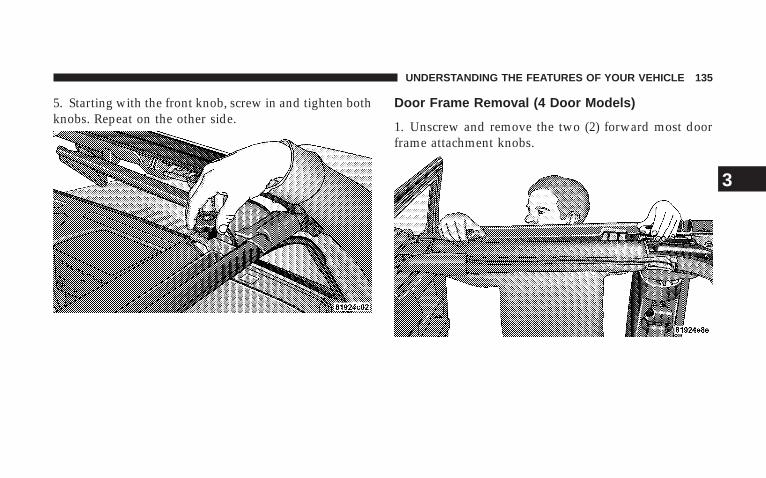
5. Starting with the front knob, screw in and tighten bothknobs. Repeat on the other side.
Door Frame Removal (4 Door Models)
1. Unscrew and remove the two (2) forward most doorframe attachment knobs.
UNDERSTANDING THE FEATURES OF YOUR VEHICLE 135
3
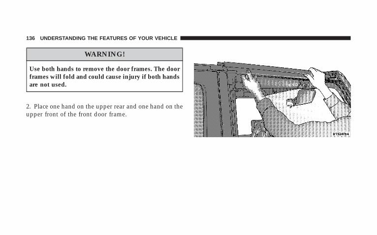
WARNING!
Use both hands to remove the door frames. The doorframes will fold and could cause injury if both handsare not used.
2. Place one hand on the upper rear and one hand on theupper front of the front door frame.
136 UNDERSTANDING THE FEATURES OF YOUR VEHICLE
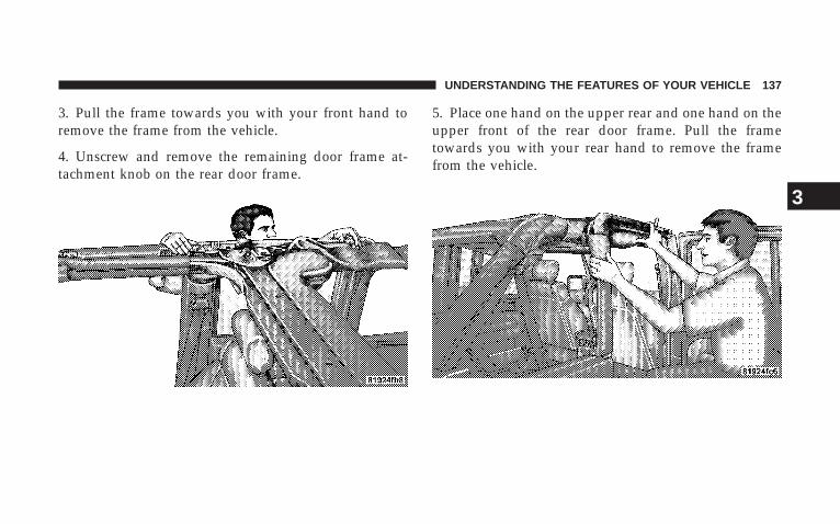
3. Pull the frame towards you with your front hand toremove the frame from the vehicle.
4. Unscrew and remove the remaining door frame at-tachment knob on the rear door frame.
5. Place one hand on the upper rear and one hand on theupper front of the rear door frame. Pull the frametowards you with your rear hand to remove the framefrom the vehicle.
UNDERSTANDING THE FEATURES OF YOUR VEHICLE 137
3
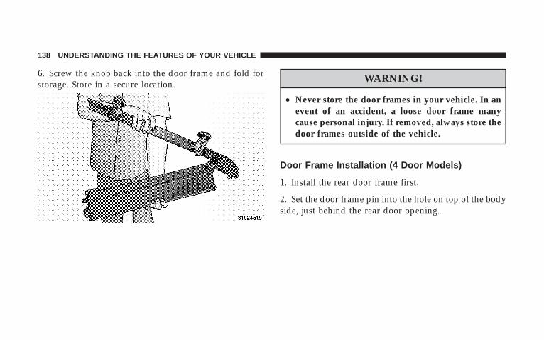
6. Screw the knob back into the door frame and fold forstorage. Store in a secure location.
WARNING!
• Never store the door frames in your vehicle. In anevent of an accident, a loose door frame manycause personal injury. If removed, always store thedoor frames outside of the vehicle.
Door Frame Installation (4 Door Models)
1. Install the rear door frame first.
2. Set the door frame pin into the hole on top of the bodyside, just behind the rear door opening.
138 UNDERSTANDING THE FEATURES OF YOUR VEHICLE
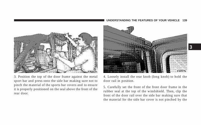
3. Position the top of the door frame against the metalsport bar and press onto the side bar making sure not topinch the material of the sports bar covers and to ensureit is properly positioned on the seal above the front of therear door.
4. Loosely install the rear knob (long knob) to hold thedoor rail in position.
5. Carefully set the front of the front door frame in therubber seal at the top of the windshield. Then, clip thefront of the door rail over the side bar making sure thatthe material for the side bar cover is not pinched by the
UNDERSTANDING THE FEATURES OF YOUR VEHICLE 139
3
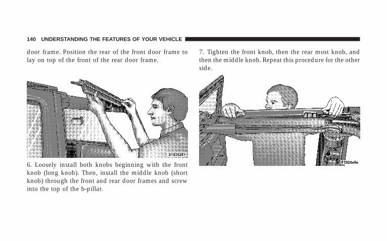
door frame. Position the rear of the front door frame tolay on top of the front of the rear door frame.
6. Loosely install both knobs beginning with the frontknob (long knob). Then, install the middle knob (shortknob) through the front and rear door frames and screwinto the top of the b-pillar.
7. Tighten the front knob, then the rear most knob, andthen the middle knob. Repeat this procedure for the otherside.
140 UNDERSTANDING THE FEATURES OF YOUR VEHICLE
SOFT TOP (2 DOOR MODELS)
CAUTION!
• The soft top is not designed to carry any additionalloads such as roof racks, spare tires, building,hunting, or camping supplies, and/or luggage, etc.Also, it was not designed as a structural member ofthe vehicle, and thus cannot properly carry anyadditional loads other than environmental (rain,snow, etc.).
If the temperature is below 72°F (24°C) and/or the tophas been folded down for a period of time, the top willappear to have shrunk when you raise it, making itdifficult to put up. This is caused by a natural contractionof the vinyl coating on the fabric top.
Place the vehicle in a warm area. Pull steadily on the topfabric. The vinyl will stretch back to its original size andthe top can then be installed. If temperature is 41°F (5°C)or below, do not attempt to put the top down or roll therear or side curtains.
UNDERSTANDING THE FEATURES OF YOUR VEHICLE 141
3
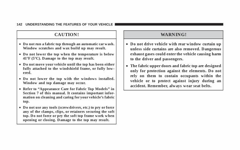
CAUTION!
• Do not run a fabric top through an automatic car wash.Window scratches and wax build up may result.
• Do not lower the top when the temperature is below41°F (5°C). Damage to the top may result.
• Do not move your vehicle until the top has been eitherfully attached to the windshield frame, or fully low-ered.
• Do not lower the top with the windows installed.Window and top damage may occur.
• Refer to “Appearance Care for Fabric Top Models” inSection 7 of this manual. It contains important infor-mation on cleaning and caring for your vehicle’s fabrictop.
• Do not use any tools (screwdrivers, etc.) to pry or forceany of the clamps, clips, or retainers securing the softtop. Do not force or pry the soft top frame work whenopening or closing. Damage to the top may result.
WARNING!
• Do not drive vehicle with rear window curtain upunless side curtains are also removed. Dangerousexhaust gases could enter the vehicle causing harmto the driver and passengers.
• The fabric upper doors and fabric top are designedonly for protection against the elements. Do notrely on them to contain occupants within thevehicle or to protect against injury during anaccident. Remember, always wear seat belts.
142 UNDERSTANDING THE FEATURES OF YOUR VEHICLE
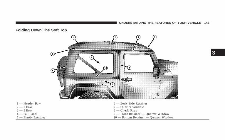
Folding Down The Soft Top
1 — Header Bow 6 — Body Side Retainer2 — 2 Bow 7 — Quarter Window3 — 3 Bow 8 — Check Strap4 — Sail Panel 9 — Front Retainer — Quarter Window5 — Plastic Retainer 10 — Bottom Retainer — Quarter Window
UNDERSTANDING THE FEATURES OF YOUR VEHICLE 143
3

1 — Zipper Start2 — Zipper Finish3 — Swing Gate Bar4 — Swing Gate Brackets5 — Sail Panels
144 UNDERSTANDING THE FEATURES OF YOUR VEHICLE
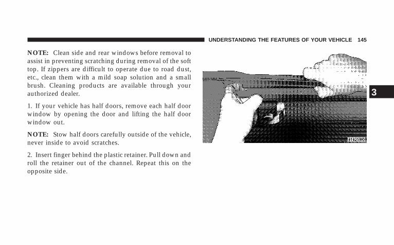
NOTE: Clean side and rear windows before removal toassist in preventing scratching during removal of the softtop. If zippers are difficult to operate due to road dust,etc., clean them with a mild soap solution and a smallbrush. Cleaning products are available through yourauthorized dealer.
1. If your vehicle has half doors, remove each half doorwindow by opening the door and lifting the half doorwindow out.
NOTE: Stow half doors carefully outside of the vehicle,never inside to avoid scratches.
2. Insert finger behind the plastic retainer. Pull down androll the retainer out of the channel. Repeat this on theopposite side.
UNDERSTANDING THE FEATURES OF YOUR VEHICLE 145
3
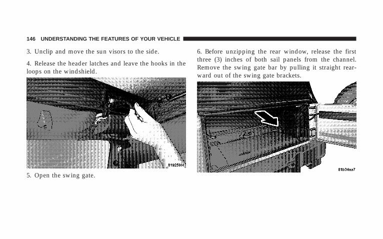
3. Unclip and move the sun visors to the side.
4. Release the header latches and leave the hooks in theloops on the windshield.
5. Open the swing gate.
6. Before unzipping the rear window, release the firstthree (3) inches of both sail panels from the channel.Remove the swing gate bar by pulling it straight rear-ward out of the swing gate brackets.
146 UNDERSTANDING THE FEATURES OF YOUR VEHICLE
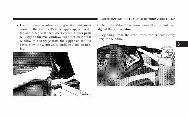
• Unzip the rear window starting at the right lowercorner of the window. Pull the zipper up, across thetop and down to the left lower corner. Zipper pullswill stay on the rear window. Pull down on the rearwindow to disengage from the zipper on the topcover. Stow the windows carefully to avoid scratch-ing.
7. Undo the Velcro� that runs along the top and rearedge of the side window.
8. Beginning from the rear lower corner, completelyunzip the window.
UNDERSTANDING THE FEATURES OF YOUR VEHICLE 147
3
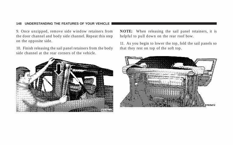
9. Once unzipped, remove side window retainers fromthe door channel and body side channel. Repeat this stepon the opposite side.
10. Finish releasing the sail panel retainers from the bodyside channel at the rear corners of the vehicle.
NOTE: When releasing the sail panel retainers, it ishelpful to pull down on the rear roof bow.
11. As you begin to lower the top, fold the sail panels sothat they rest on top of the soft top.
148 UNDERSTANDING THE FEATURES OF YOUR VEHICLE
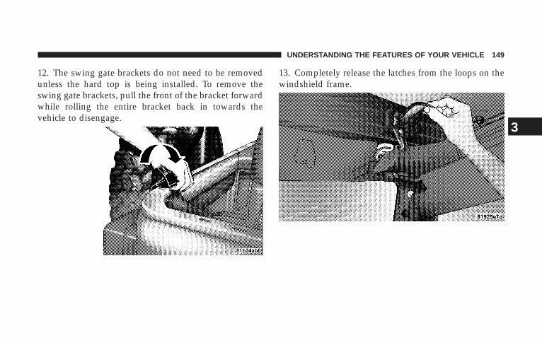
12. The swing gate brackets do not need to be removedunless the hard top is being installed. To remove theswing gate brackets, pull the front of the bracket forwardwhile rolling the entire bracket back in towards thevehicle to disengage.
13. Completely release the latches from the loops on thewindshield frame.
UNDERSTANDING THE FEATURES OF YOUR VEHICLE 149
3
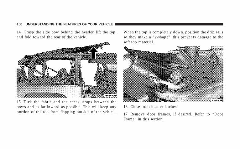
14. Grasp the side bow behind the header, lift the top,and fold toward the rear of the vehicle.
15. Tuck the fabric and the check straps between thebows and as far inward as possible. This will keep anyportion of the top from flapping outside of the vehicle.
When the top is completely down, position the drip railsso they make a “v-shape”, this prevents damage to thesoft top material.
16. Close front header latches.
17. Remove door frames, if desired. Refer to “DoorFrame” in this section.
150 UNDERSTANDING THE FEATURES OF YOUR VEHICLE
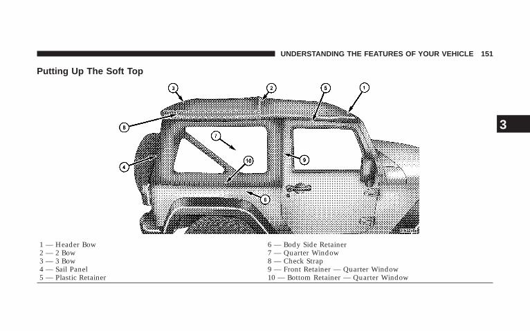
Putting Up The Soft Top
1 — Header Bow 6 — Body Side Retainer2 — 2 Bow 7 — Quarter Window3 — 3 Bow 8 — Check Strap4 — Sail Panel 9 — Front Retainer — Quarter Window5 — Plastic Retainer 10 — Bottom Retainer — Quarter Window
UNDERSTANDING THE FEATURES OF YOUR VEHICLE 151
3
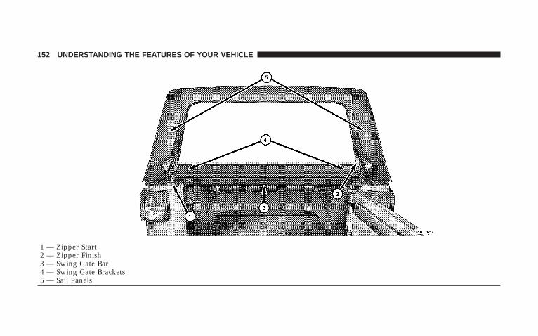
1 — Zipper Start2 — Zipper Finish3 — Swing Gate Bar4 — Swing Gate Brackets5 — Sail Panels
152 UNDERSTANDING THE FEATURES OF YOUR VEHICLE
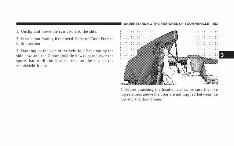
1. Unclip and move the sun visors to the side.
2. Install door frames, if removed. Refer to “Door Frame”in this section.
3. Standing on the side of the vehicle, lift the top by theside bow and the 2–bow (middle bow) up and over thesports bar until the header rests on the top of thewindshield frame.
4. Before attaching the header latches, be sure that thetop retainers above the door are not trapped between thetop and the door frame.
UNDERSTANDING THE FEATURES OF YOUR VEHICLE 153
3
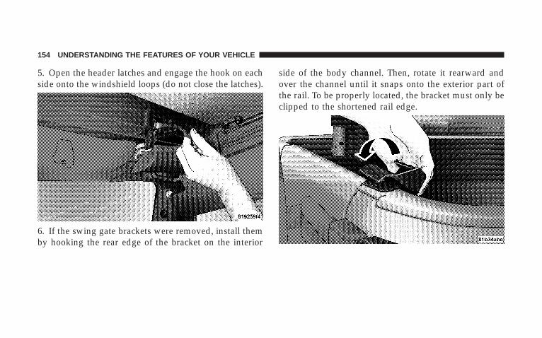
5. Open the header latches and engage the hook on eachside onto the windshield loops (do not close the latches).
6. If the swing gate brackets were removed, install themby hooking the rear edge of the bracket on the interior
side of the body channel. Then, rotate it rearward andover the channel until it snaps onto the exterior part ofthe rail. To be properly located, the bracket must only beclipped to the shortened rail edge.
154 UNDERSTANDING THE FEATURES OF YOUR VEHICLE
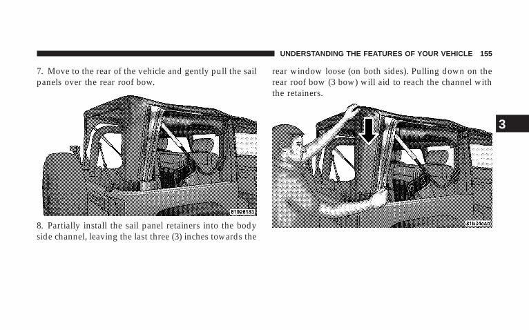
7. Move to the rear of the vehicle and gently pull the sailpanels over the rear roof bow.
8. Partially install the sail panel retainers into the bodyside channel, leaving the last three (3) inches towards the
rear window loose (on both sides). Pulling down on therear roof bow (3 bow) will aid to reach the channel withthe retainers.
UNDERSTANDING THE FEATURES OF YOUR VEHICLE 155
3
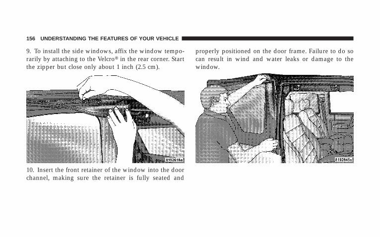
9. To install the side windows, affix the window tempo-rarily by attaching to the Velcro� in the rear corner. Startthe zipper but close only about 1 inch (2.5 cm).
10. Insert the front retainer of the window into the doorchannel, making sure the retainer is fully seated and
properly positioned on the door frame. Failure to do socan result in wind and water leaks or damage to thewindow.
156 UNDERSTANDING THE FEATURES OF YOUR VEHICLE
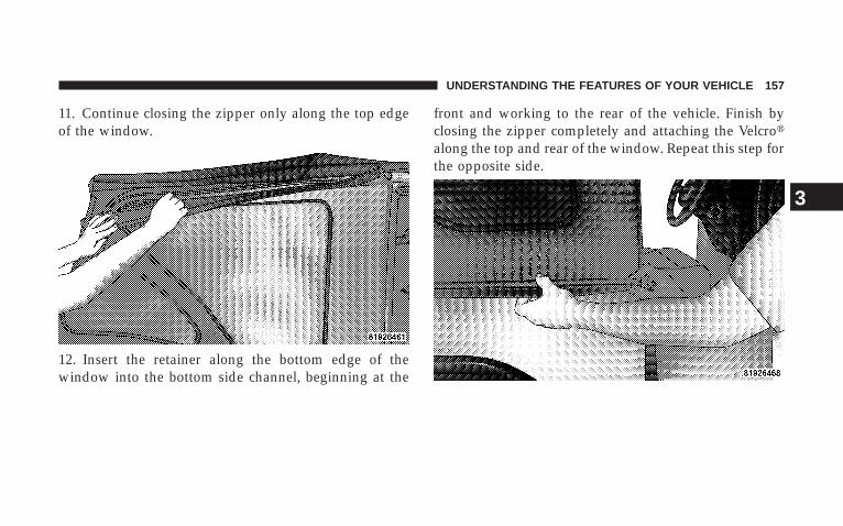
11. Continue closing the zipper only along the top edgeof the window.
12. Insert the retainer along the bottom edge of thewindow into the bottom side channel, beginning at the
front and working to the rear of the vehicle. Finish byclosing the zipper completely and attaching the Velcro�along the top and rear of the window. Repeat this step forthe opposite side.
UNDERSTANDING THE FEATURES OF YOUR VEHICLE 157
3
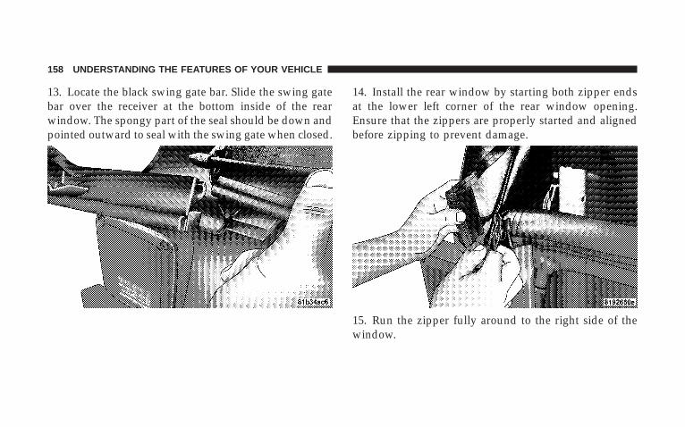
13. Locate the black swing gate bar. Slide the swing gatebar over the receiver at the bottom inside of the rearwindow. The spongy part of the seal should be down andpointed outward to seal with the swing gate when closed.
14. Install the rear window by starting both zipper endsat the lower left corner of the rear window opening.Ensure that the zippers are properly started and alignedbefore zipping to prevent damage.
15. Run the zipper fully around to the right side of thewindow.
158 UNDERSTANDING THE FEATURES OF YOUR VEHICLE
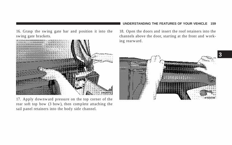
16. Grasp the swing gate bar and position it into theswing gate brackets.
17. Apply downward pressure on the top corner of therear soft top bow (3 bow), then complete attaching thesail panel retainers into the body side channel.
18. Open the doors and insert the roof retainers into thechannels above the door, starting at the front and work-ing rearward.
UNDERSTANDING THE FEATURES OF YOUR VEHICLE 159
3
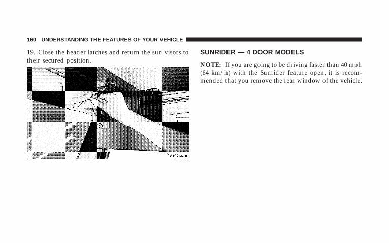
19. Close the header latches and return the sun visors totheir secured position.
SUNRIDER — 4 DOOR MODELS
NOTE: If you are going to be driving faster than 40 mph(64 km/h) with the Sunrider feature open, it is recom-mended that you remove the rear window of the vehicle.
160 UNDERSTANDING THE FEATURES OF YOUR VEHICLE
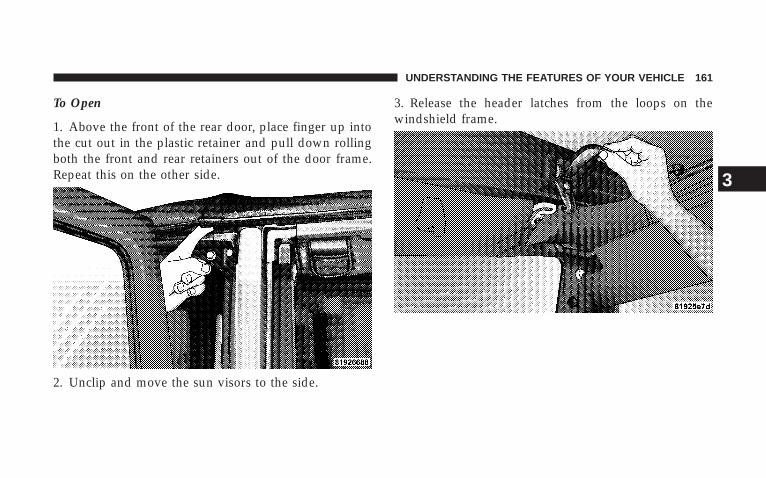
To Open
1. Above the front of the rear door, place finger up intothe cut out in the plastic retainer and pull down rollingboth the front and rear retainers out of the door frame.Repeat this on the other side.
2. Unclip and move the sun visors to the side.
3. Release the header latches from the loops on thewindshield frame.
UNDERSTANDING THE FEATURES OF YOUR VEHICLE 161
3
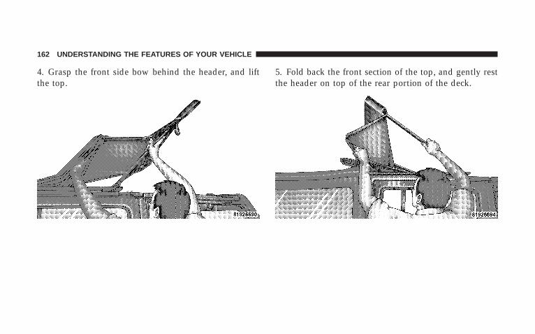
4. Grasp the front side bow behind the header, and liftthe top.
5. Fold back the front section of the top, and gently restthe header on top of the rear portion of the deck.
162 UNDERSTANDING THE FEATURES OF YOUR VEHICLE
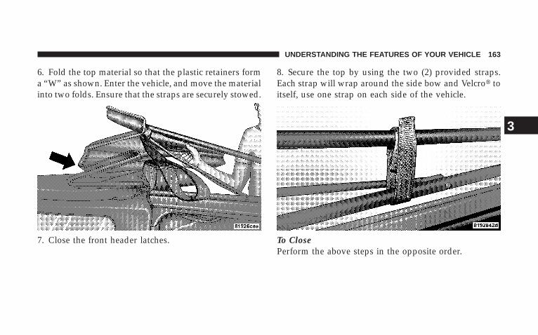
6. Fold the top material so that the plastic retainers forma “W” as shown. Enter the vehicle, and move the materialinto two folds. Ensure that the straps are securely stowed.
7. Close the front header latches.
8. Secure the top by using the two (2) provided straps.Each strap will wrap around the side bow and Velcro� toitself, use one strap on each side of the vehicle.
To ClosePerform the above steps in the opposite order.
UNDERSTANDING THE FEATURES OF YOUR VEHICLE 163
3
SOFT TOP (4 DOOR MODELS)
CAUTION!
• The soft top is not designed to carry any additionalloads such as roof racks, spare tires, building,hunting, or camping supplies, and/or luggage, etc.Also, it was not designed as a structural member ofthe vehicle, and thus cannot properly carry anyadditional loads other than environmental (rain,snow, etc.).
If the temperature is below 72°F (24°C) and/or the tophas been folded down for a period of time, the top willappear to have shrunk when you raise it, making itdifficult to put up. This is caused by a natural contractionof the vinyl coating on the fabric top.
Place the vehicle in a warm area. Pull steadily on the topfabric. The vinyl will stretch back to its original size andthe top can then be snapped into place. If temperature is41°F (5°C) or below, do not attempt to put the top downor roll the rear or side curtains.
164 UNDERSTANDING THE FEATURES OF YOUR VEHICLE
CAUTION!
• Do not run a fabric top through an automatic car wash.Window scratches and wax build up may result.
• Do not lower the top when the temperature is below 41°F(5°C). Damage to the top may result.
• Do not lower the top when the windows are dirty. Gritmay scratch the window.
• Do not move your vehicle until the top has been eitherfully attached to the windshield frame, or fully lowered.
• Do not lower the top with the windows installed. Win-dow and top damage may occur.
• Refer to “Appearance Care for Fabric Top Models” inSection 7 of this manual. It contains important informa-tion on cleaning and caring for your vehicle’s fabric top.
• Do not use any tools (screwdrivers, etc.) to pry or forceany of the clamps, clips, or retainers securing the soft top.Do not force or pry the soft top frame work whenopening or closing. Damage to the top may result.
WARNING!
• Do not drive vehicle with rear window curtain upunless side curtains are also open. Dangerousexhaust gases which can kill could enter the ve-hicle.
• The fabric upper doors and fabric top are designedonly for protection against the elements. Do notrely on them to contain occupants within thevehicle or to protect against injury during anaccident. Remember, always wear seat belts.
UNDERSTANDING THE FEATURES OF YOUR VEHICLE 165
3
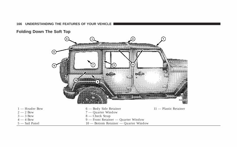
Folding Down The Soft Top
1 — Header Bow 6 — Body Side Retainer 11 — Plastic Retainer2 — 2 Bow 7 — Quarter Window3 — 3 Bow 8 — Check Strap4 — 4 Bow 9 — Front Retainer — Quarter Window5 — Sail Panel 10 — Bottom Retainer — Quarter Window
166 UNDERSTANDING THE FEATURES OF YOUR VEHICLE

1 — Zipper Start2 — Zipper Finish3 — Swing Gate Bar4 — Swing Gate Brackets5 — Sail Panels
UNDERSTANDING THE FEATURES OF YOUR VEHICLE 167
3
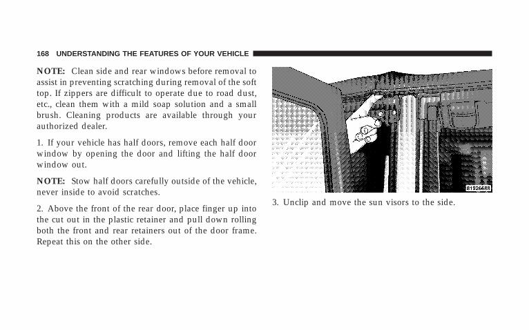
NOTE: Clean side and rear windows before removal toassist in preventing scratching during removal of the softtop. If zippers are difficult to operate due to road dust,etc., clean them with a mild soap solution and a smallbrush. Cleaning products are available through yourauthorized dealer.
1. If your vehicle has half doors, remove each half doorwindow by opening the door and lifting the half doorwindow out.
NOTE: Stow half doors carefully outside of the vehicle,never inside to avoid scratches.
2. Above the front of the rear door, place finger up intothe cut out in the plastic retainer and pull down rollingboth the front and rear retainers out of the door frame.Repeat this on the other side.
3. Unclip and move the sun visors to the side.
168 UNDERSTANDING THE FEATURES OF YOUR VEHICLE
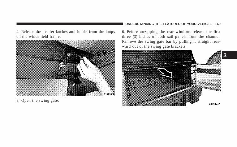
4. Release the header latches and hooks from the loopson the windshield frame.
5. Open the swing gate.
6. Before unzipping the rear window, release the firstthree (3) inches of both sail panels from the channel.Remove the swing gate bar by pulling it straight rear-ward out of the swing gate brackets.
UNDERSTANDING THE FEATURES OF YOUR VEHICLE 169
3
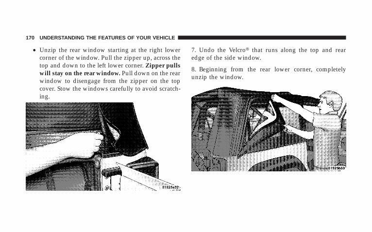
• Unzip the rear window starting at the right lowercorner of the window. Pull the zipper up, across thetop and down to the left lower corner. Zipper pullswill stay on the rear window. Pull down on the rearwindow to disengage from the zipper on the topcover. Stow the windows carefully to avoid scratch-ing.
7. Undo the Velcro� that runs along the top and rearedge of the side window.
8. Beginning from the rear lower corner, completelyunzip the window.
170 UNDERSTANDING THE FEATURES OF YOUR VEHICLE
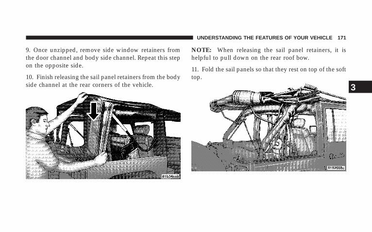
9. Once unzipped, remove side window retainers fromthe door channel and body side channel. Repeat this stepon the opposite side.
10. Finish releasing the sail panel retainers from the bodyside channel at the rear corners of the vehicle.
NOTE: When releasing the sail panel retainers, it ishelpful to pull down on the rear roof bow.
11. Fold the sail panels so that they rest on top of the softtop.
UNDERSTANDING THE FEATURES OF YOUR VEHICLE 171
3
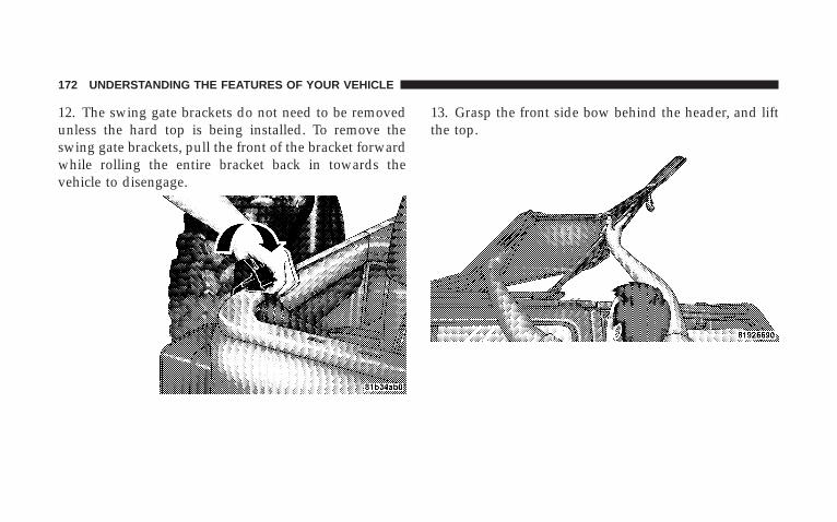
12. The swing gate brackets do not need to be removedunless the hard top is being installed. To remove theswing gate brackets, pull the front of the bracket forwardwhile rolling the entire bracket back in towards thevehicle to disengage.
13. Grasp the front side bow behind the header, and liftthe top.
172 UNDERSTANDING THE FEATURES OF YOUR VEHICLE

14. Fold back the front section of the top, and gently restthe header on top of the rear portion of the deck.
15. Fold the top material so that the plastic retainers forma “W” as shown. Enter the vehicle, and move the materialinto two folds.
UNDERSTANDING THE FEATURES OF YOUR VEHICLE 173
3

16. Release the side bows by pressing down on the latchabove the front of the rear door. Push the top rearward todisengage. Repeat this step on the other side.
17. Grasp the folded side bows and slide the top alongthe door frame track to the rear door frame.
174 UNDERSTANDING THE FEATURES OF YOUR VEHICLE
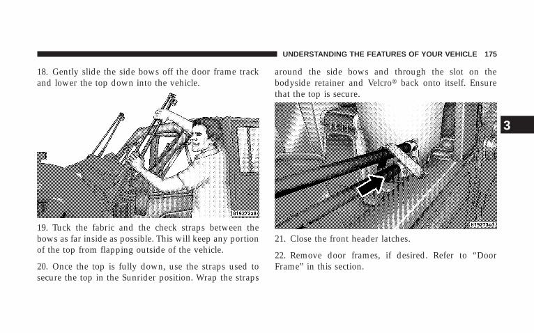
18. Gently slide the side bows off the door frame trackand lower the top down into the vehicle.
19. Tuck the fabric and the check straps between thebows as far inside as possible. This will keep any portionof the top from flapping outside of the vehicle.
20. Once the top is fully down, use the straps used tosecure the top in the Sunrider position. Wrap the straps
around the side bows and through the slot on thebodyside retainer and Velcro� back onto itself. Ensurethat the top is secure.
21. Close the front header latches.
22. Remove door frames, if desired. Refer to “DoorFrame” in this section.
UNDERSTANDING THE FEATURES OF YOUR VEHICLE 175
3

Putting Up The Soft Top
1 — Header Bow 6 — Body Side Retainer 11 — Plastic Retainer2 — 2 Bow 7 — Quarter Window3 — 3 Bow 8 — Check Strap4 — 4 Bow 9 — Front Retainer — Quarter Window5 — Sail Panel 10 — Bottom Retainer — Quarter Window
176 UNDERSTANDING THE FEATURES OF YOUR VEHICLE
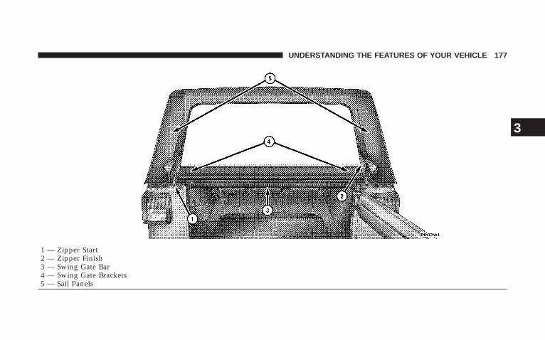
1 — Zipper Start2 — Zipper Finish3 — Swing Gate Bar4 — Swing Gate Brackets5 — Sail Panels
UNDERSTANDING THE FEATURES OF YOUR VEHICLE 177
3
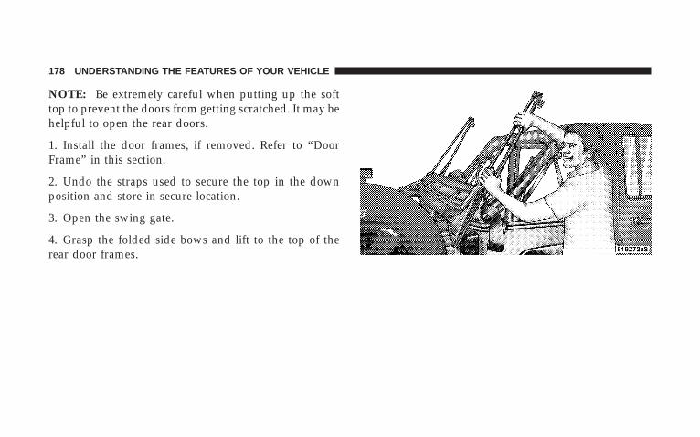
NOTE: Be extremely careful when putting up the softtop to prevent the doors from getting scratched. It may behelpful to open the rear doors.
1. Install the door frames, if removed. Refer to “DoorFrame” in this section.
2. Undo the straps used to secure the top in the downposition and store in secure location.
3. Open the swing gate.
4. Grasp the folded side bows and lift to the top of therear door frames.
178 UNDERSTANDING THE FEATURES OF YOUR VEHICLE
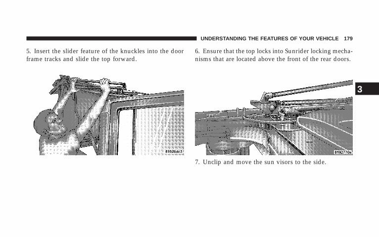
5. Insert the slider feature of the knuckles into the doorframe tracks and slide the top forward.
6. Ensure that the top locks into Sunrider locking mecha-nisms that are located above the front of the rear doors.
7. Unclip and move the sun visors to the side.
UNDERSTANDING THE FEATURES OF YOUR VEHICLE 179
3
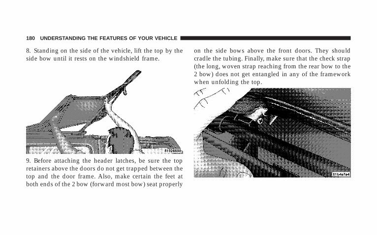
8. Standing on the side of the vehicle, lift the top by theside bow until it rests on the windshield frame.
9. Before attaching the header latches, be sure the topretainers above the doors do not get trapped between thetop and the door frame. Also, make certain the feet atboth ends of the 2 bow (forward most bow) seat properly
on the side bows above the front doors. They shouldcradle the tubing. Finally, make sure that the check strap(the long, woven strap reaching from the rear bow to the2 bow) does not get entangled in any of the frameworkwhen unfolding the top.
180 UNDERSTANDING THE FEATURES OF YOUR VEHICLE
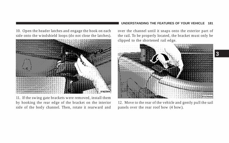
10. Open the header latches and engage the hook on eachside onto the windshield loops (do not close the latches).
11. If the swing gate brackets were removed, install themby hooking the rear edge of the bracket on the interiorside of the body channel. Then, rotate it rearward and
over the channel until it snaps onto the exterior part ofthe rail. To be properly located, the bracket must only beclipped to the shortened rail edge.
12. Move to the rear of the vehicle and gently pull the sailpanels over the rear roof bow (4 bow).
UNDERSTANDING THE FEATURES OF YOUR VEHICLE 181
3
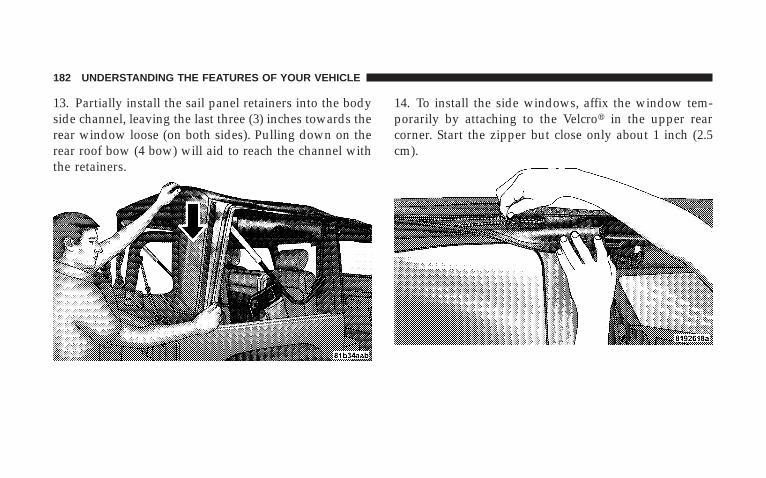
13. Partially install the sail panel retainers into the bodyside channel, leaving the last three (3) inches towards therear window loose (on both sides). Pulling down on therear roof bow (4 bow) will aid to reach the channel withthe retainers.
14. To install the side windows, affix the window tem-porarily by attaching to the Velcro� in the upper rearcorner. Start the zipper but close only about 1 inch (2.5cm).
182 UNDERSTANDING THE FEATURES OF YOUR VEHICLE
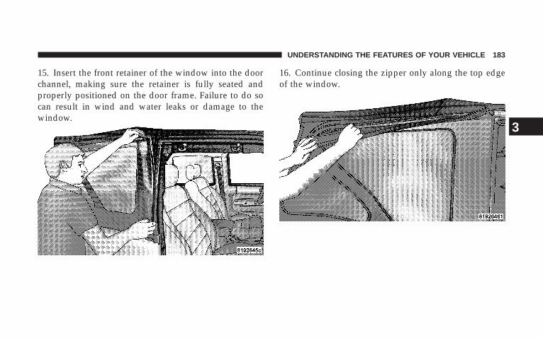
15. Insert the front retainer of the window into the doorchannel, making sure the retainer is fully seated andproperly positioned on the door frame. Failure to do socan result in wind and water leaks or damage to thewindow.
16. Continue closing the zipper only along the top edgeof the window.
UNDERSTANDING THE FEATURES OF YOUR VEHICLE 183
3
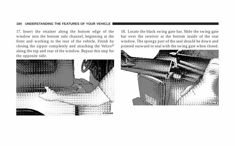
17. Insert the retainer along the bottom edge of thewindow into the bottom side channel, beginning at thefront and working to the rear of the vehicle. Finish byclosing the zipper completely and attaching the Velcro�along the top and rear of the window. Repeat this step forthe opposite side.
18. Locate the black swing gate bar. Slide the swing gatebar over the receiver at the bottom inside of the rearwindow. The spongy part of the seal should be down andpointed outward to seal with the swing gate when closed.
184 UNDERSTANDING THE FEATURES OF YOUR VEHICLE

19. Install the rear window by starting both zipper endsat the lower left corner of the rear window opening.Ensure that the zippers are properly started and alignedbefore zipping to prevent damage.
20. Run the first zipper fully around to the right side ofthe window.
21. Grasp the swing gate bar and position it into theswing gate brackets.
22. Complete the installation of the sail panel by insert-ing the rest of the retainer into the body channel.
UNDERSTANDING THE FEATURES OF YOUR VEHICLE 185
3
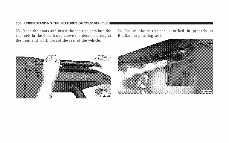
23. Open the doors and insert the top retainers into thechannels in the door frame above the doors, starting atthe front and work toward the rear of the vehicle.
24. Ensure plastic retainer is tucked in properly atB-pillar not pinching seal.
186 UNDERSTANDING THE FEATURES OF YOUR VEHICLE
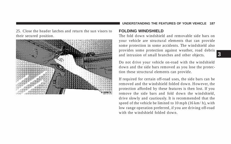
25. Close the header latches and return the sun visors totheir secured position.
FOLDING WINDSHIELDThe fold down windshield and removable side bars onyour vehicle are structural elements that can providesome protection in some accidents. The windshield alsoprovides some protection against weather, road debrisand intrusion of small branches and other objects.
Do not drive your vehicle on-road with the windshielddown and the side bars removed as you lose the protec-tion these structural elements can provide.
If required for certain off-road uses, the side bars can beremoved and the windshield folded down. However, theprotection afforded by these features is then lost. If youremove the side bars and fold down the windshield,drive slowly and cautiously. It is recommended that thespeed of the vehicle be limited to 10 mph (16 km/h), withlow range operation preferred, if you are driving off-roadwith the windshield folded down.
UNDERSTANDING THE FEATURES OF YOUR VEHICLE 187
3
Raise the windshield and reinstall the side bars as soon asthe task that required their removal is completed andbefore you return to on-road driving. Both you and yourpassenger should wear seat belts at all times, on-road andoff-road, regardless of whether the windshield is raisedor folded down.
Outside rear view mirrors are mounted on the doors. Ifyou choose to remove the doors, see your authorizeddealer for a replacement cowl-mounted outside mirror.Federal law requires outside mirrors on vehicles foron-road use.
WARNING!
Carefully follow these warnings to help protect againstpersonal injury:
• Do not drive your vehicle on-road with the windshielddown.
• Do not drive your vehicle unless the windshield issecurely fastened, either up or down.
• Eye protection, such as goggles, should be worn at alltimes when the windshield is down.
• Be sure that you carefully follow the instructions forraising the windshield. Make sure that the folding wind-shield, windshield wipers, side bars, and all associatedhardware and fasteners are correctly and tightly as-sembled before driving your vehicle. Failure to followthese instructions may prevent your vehicle from provid-ing you and your passengers protection in some accidents.
• If you remove the doors, store them outside the vehicle.In the event of an accident, a loose door may causepersonal injury.
188 UNDERSTANDING THE FEATURES OF YOUR VEHICLE
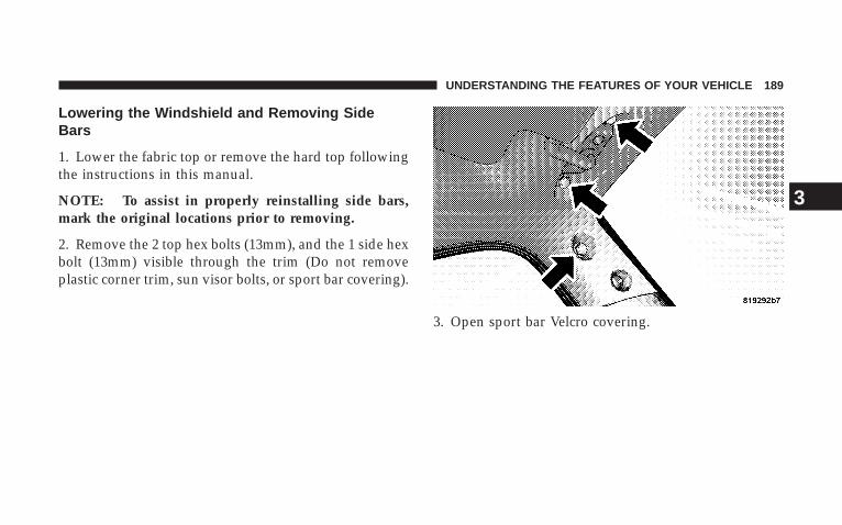
Lowering the Windshield and Removing SideBars
1. Lower the fabric top or remove the hard top followingthe instructions in this manual.
NOTE: To assist in properly reinstalling side bars,mark the original locations prior to removing.
2. Remove the 2 top hex bolts (13mm), and the 1 side hexbolt (13mm) visible through the trim (Do not removeplastic corner trim, sun visor bolts, or sport bar covering).
3. Open sport bar Velcro covering.
UNDERSTANDING THE FEATURES OF YOUR VEHICLE 189
3
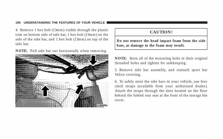
4. Remove 1 hex bolt (13mm) visible through the plastictrim on bottom side of side bar, 1 hex bolt (13mm) on theside of the side bar, and 1 hex bolt (13mm) on top of theside bar.
NOTE: Pull side bar out horizontally when removing.
CAUTION!
Do not remove the head impact foam from the sidebars, as damage to the foam may result.
NOTE: Store all of the mounting bolts in their originalthreaded holes and tighten for safekeeping.
5. Remove side bar assembly, and reattach sport barVelcro covering.
6. To safely store the side bars in your vehicle, use fourcinch straps (available from your authorized dealer).Attach the straps through the slots located on the floorbehind the folded rear seat at the front of the storage bincover.
190 UNDERSTANDING THE FEATURES OF YOUR VEHICLE
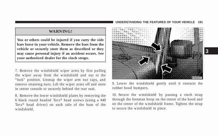
WARNING!
You or others could be injured if you carry the sidebars loose in your vehicle. Remove the bars from thevehicle or securely store them as described or theymay cause personal injury if an accident occurs. Seeyour authorized dealer for the cinch straps.
7. Remove the windshield wiper arms by first pullingthe wiper away from the windshield and out to the“lock” position. Unsnap the wiper arm nut caps, andremove retaining nuts. Lift the wiper arms off and storein center console or securely behind the rear seat.
8. Remove the lower windshield plates by removing the6 black round headed Torx� head screws (using a #40Torx� head driver) on each side of the base of thewindshield.
9. Lower the windshield gently until it contacts therubber hood bumpers.
10. Secure the windshield by passing a cinch strapthrough the footman hoop on the center of the hood andon the center of the windshield frame. Tighten the strapto secure the windshield in place.
UNDERSTANDING THE FEATURES OF YOUR VEHICLE 191
3
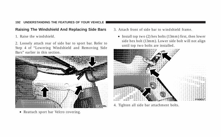
Raising The Windshield And Replacing Side Bars
1. Raise the windshield.
2. Loosely attach rear of side bar to sport bar. Refer toStep 4 of “Lowering Windshield and Removing SideBars” earlier in this section.
• Reattach sport bar Velcro covering.
3. Attach front of side bar to windshield frame.
• Install top two (2) hex bolts (13mm) first, then lowerside hex bolt (13mm). Lower side bolt will not alignuntil top two bolts are installed.
4. Tighten all side bar attachment bolts.
192 UNDERSTANDING THE FEATURES OF YOUR VEHICLE
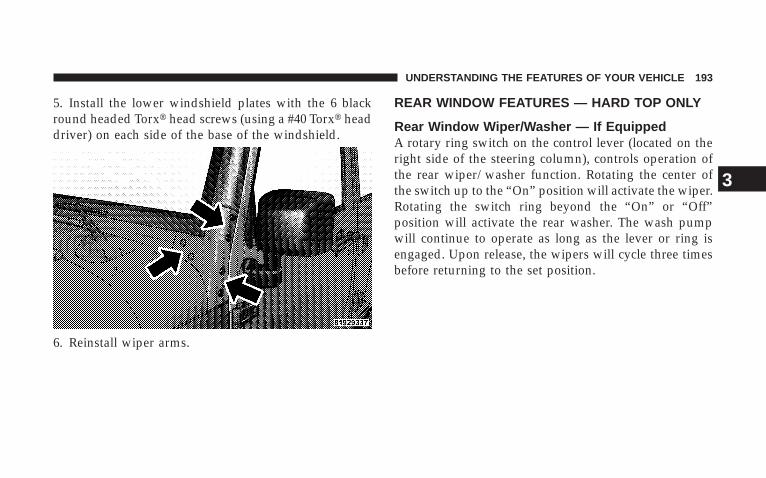
5. Install the lower windshield plates with the 6 blackround headed Torx� head screws (using a #40 Torx� headdriver) on each side of the base of the windshield.
6. Reinstall wiper arms.
REAR WINDOW FEATURES — HARD TOP ONLY
Rear Window Wiper/Washer — If EquippedA rotary ring switch on the control lever (located on theright side of the steering column), controls operation ofthe rear wiper/washer function. Rotating the center ofthe switch up to the “On” position will activate the wiper.Rotating the switch ring beyond the “On” or “Off”position will activate the rear washer. The wash pumpwill continue to operate as long as the lever or ring isengaged. Upon release, the wipers will cycle three timesbefore returning to the set position.
UNDERSTANDING THE FEATURES OF YOUR VEHICLE 193
3

If the rear wiper is operating when the ignition is turnedOFF, the wiper will automatically return to the “Park”position. When the vehicle is restarted, the wiper willresume function at whichever position the switch is setat.
If the swing gate flip-up window is open or the swinggate is open, connection to the rear window wiper isinterrupted preventing activation of the rear wiper blade.When the swing gate flip-up window or the swing gate isclosed, the rear wiper switch or the ignition switch needsto be turned OFF, and then to ON to restart the rearwiper.
NOTE: The rear swing gate will lock while the rearwiper is operating. The gate will stay locked until thewiper is turned off and the gate is unlocked (by key,lock switch, or key fob).
Adding Washer FluidThe fluid reservoir for the windshield washers and therear window washer is shared. It is located in the front ofthe engine compartment, and should be checked for fluid
Windshield Wiper/Washer Switch
194 UNDERSTANDING THE FEATURES OF YOUR VEHICLE
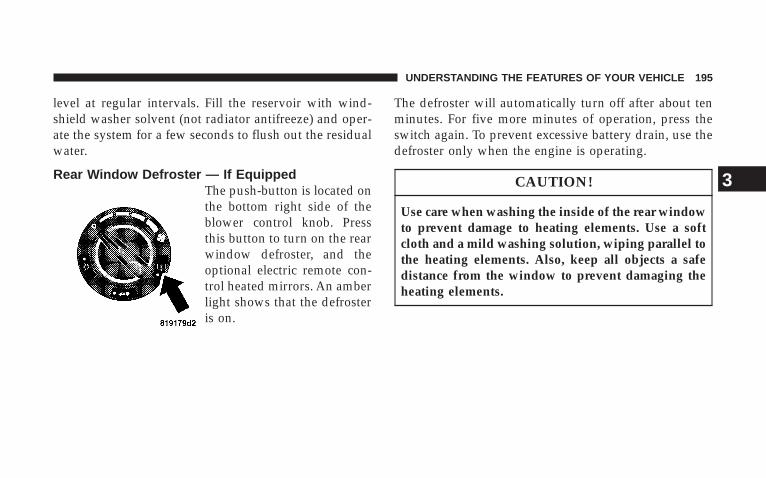
level at regular intervals. Fill the reservoir with wind-shield washer solvent (not radiator antifreeze) and oper-ate the system for a few seconds to flush out the residualwater.
Rear Window Defroster — If EquippedThe push-button is located onthe bottom right side of theblower control knob. Pressthis button to turn on the rearwindow defroster, and theoptional electric remote con-trol heated mirrors. An amberlight shows that the defrosteris on.
The defroster will automatically turn off after about tenminutes. For five more minutes of operation, press theswitch again. To prevent excessive battery drain, use thedefroster only when the engine is operating.
CAUTION!
Use care when washing the inside of the rear windowto prevent damage to heating elements. Use a softcloth and a mild washing solution, wiping parallel tothe heating elements. Also, keep all objects a safedistance from the window to prevent damaging theheating elements.
UNDERSTANDING THE FEATURES OF YOUR VEHICLE 195
3

UNDERSTANDING YOUR INSTRUMENT PANEL
CONTENTS
� Instrument Panel And Controls . . . . . . . . . . . . . 200
� Instrument Cluster . . . . . . . . . . . . . . . . . . . . . . 201
� Instrument Cluster Description . . . . . . . . . . . . . 202
� Compass And Trip Computer — If Equipped . . . 211
▫ Control Buttons . . . . . . . . . . . . . . . . . . . . . . 211
▫ Trip Conditions . . . . . . . . . . . . . . . . . . . . . . . 212
▫ Compass Temperature Display . . . . . . . . . . . . 213
� Radio General Information . . . . . . . . . . . . . . . . 216
▫ Radio Broadcast Signals . . . . . . . . . . . . . . . . . 216
▫ Two Types Of Signals . . . . . . . . . . . . . . . . . . 216
▫ Electrical Disturbances . . . . . . . . . . . . . . . . . . 216
▫ AM Reception . . . . . . . . . . . . . . . . . . . . . . . 216
▫ FM Reception . . . . . . . . . . . . . . . . . . . . . . . . 217
� Sales Code REQ — AM/FM Stereo RadioAnd 6–Disc CD/DVD Changer(MP3/WMA Aux Jack) . . . . . . . . . . . . . . . . . . . 217
▫ Operating Instructions - Radio Mode . . . . . . . 217
▫ Operation Instructions - (Disc Mode For CDAnd MP3/WMA Audio Play, DVD-Video) . . . . 226
4
▫ Notes On Playing MP3/WMA Files . . . . . . . . 228
▫ List Button (Disc Mode For MP3/WMAPlay) . . . . . . . . . . . . . . . . . . . . . . . . . . . . . . 230
▫ Info Button (Disc Mode For MP3/WMAPlay) . . . . . . . . . . . . . . . . . . . . . . . . . . . . . . 231
� Sales Code RES — AM/FM Stereo RadioWith CD Player (MP3 Aux Jack) . . . . . . . . . . . . 233
▫ Operating Instructions - Radio Mode . . . . . . . 233
▫ Operation Instructions - CD Mode For CDAnd MP3 Audio Play . . . . . . . . . . . . . . . . . . 239
▫ Notes On Playing MP3 Files . . . . . . . . . . . . . 241
▫ List Button (CD Mode For MP3 Play) . . . . . . . 244
▫ Info Button (CD Mode For MP3 Play) . . . . . . . 244
� Sales Code RER — AM/FM/CD/DVD RadioWith Navigation System — If Equipped . . . . . . . 245
▫ Operating Instructions — Satellite Radio . . . . . 246
▫ Clock Setting Procedure . . . . . . . . . . . . . . . . . 246
� Satellite Radio — If Equipped . . . . . . . . . . . . . . 247
▫ System Activation . . . . . . . . . . . . . . . . . . . . . 247
▫ Electronic Serial Number/Sirius IdentificationNumber (ENS/SID) . . . . . . . . . . . . . . . . . . . . 248
▫ Selecting Satellite Mode (RSC Radios) . . . . . . . 248
▫ Satellite Antenna . . . . . . . . . . . . . . . . . . . . . . 248
▫ Reception Quality . . . . . . . . . . . . . . . . . . . . . 248
▫ Operating Instructions - Satellite Mode . . . . . . 249
▫ Operating Instructions - Hands Free Phone(If Equipped) . . . . . . . . . . . . . . . . . . . . . . . . 251
▫ Operating Instructions - Video EntertainmentSystem (VES�) (If Equipped) . . . . . . . . . . . . . 251
198 UNDERSTANDING YOUR INSTRUMENT PANEL
� CD/DVD Disc Maintenance . . . . . . . . . . . . . . . 251
� Radio Operation And Cellular Phones . . . . . . . . 252
� Climate Controls . . . . . . . . . . . . . . . . . . . . . . . 252
▫ Manual Heater Only . . . . . . . . . . . . . . . . . . . 252
▫ Manual Air Conditioning And HeatingSystem — If Equipped . . . . . . . . . . . . . . . . . . 254
▫ Operating Tips . . . . . . . . . . . . . . . . . . . . . . . 258
UNDERSTANDING YOUR INSTRUMENT PANEL 199
4
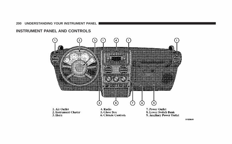
INSTRUMENT PANEL AND CONTROLS
200 UNDERSTANDING YOUR INSTRUMENT PANEL
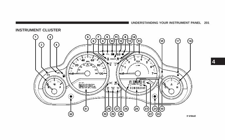
INSTRUMENT CLUSTER
UNDERSTANDING YOUR INSTRUMENT PANEL 201
4
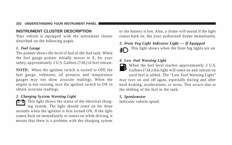
INSTRUMENT CLUSTER DESCRIPTIONYour vehicle is equipped with the instrument clusterdescribed on the following pages.
1. Fuel GaugeThe pointer shows the level of fuel in the fuel tank. Whenthe fuel gauge pointer initially moves to E, for yoursafety, approximately 2 U.S. Gallons (7.6L) of fuel remain.
NOTE: When the ignition switch is turned to OFF, thefuel gauge, voltmeter, oil pressure and temperaturegauges may not show accurate readings. When theengine is not running, turn the ignition switch to ON toobtain accurate readings.
2. Charging System Warning LightThis light shows the status of the electrical charg-ing system. The light should come on for three
seconds when the ignition is first turned ON. If the lightcomes back on immediately or comes on while driving, itmeans that there is a problem with the charging system
or the battery is low. Also, a chime will sound if the lightcomes back on. See your authorized dealer immediately.
3. Front Fog Light Indicator Light — If EquippedThis light shows when the front fog lights are on.
4. Low Fuel Warning LightWhen the fuel level reaches approximately 2 U.S.Gallons (7.6L) this light will come on and remain onuntil fuel is added. The “Low Fuel Warning Light”
may turn on and off again, especially during and afterhard braking, accelerations, or turns. This occurs due tothe shifting of the fuel in the tank.
5. SpeedometerIndicates vehicle speed.
202 UNDERSTANDING YOUR INSTRUMENT PANEL
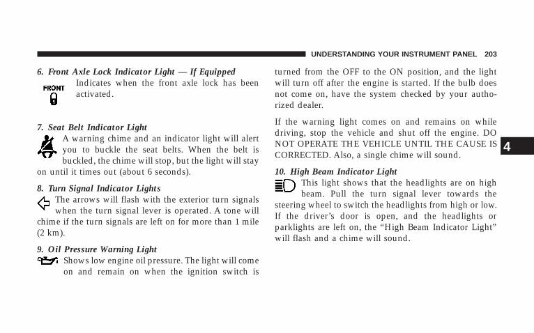
6. Front Axle Lock Indicator Light — If EquippedIndicates when the front axle lock has beenactivated.
7. Seat Belt Indicator LightA warning chime and an indicator light will alertyou to buckle the seat belts. When the belt isbuckled, the chime will stop, but the light will stay
on until it times out (about 6 seconds).
8. Turn Signal Indicator LightsThe arrows will flash with the exterior turn signalswhen the turn signal lever is operated. A tone will
chime if the turn signals are left on for more than 1 mile(2 km).
9. Oil Pressure Warning LightShows low engine oil pressure. The light will comeon and remain on when the ignition switch is
turned from the OFF to the ON position, and the lightwill turn off after the engine is started. If the bulb doesnot come on, have the system checked by your autho-rized dealer.
If the warning light comes on and remains on whiledriving, stop the vehicle and shut off the engine. DONOT OPERATE THE VEHICLE UNTIL THE CAUSE ISCORRECTED. Also, a single chime will sound.
10. High Beam Indicator LightThis light shows that the headlights are on highbeam. Pull the turn signal lever towards the
steering wheel to switch the headlights from high or low.If the driver’s door is open, and the headlights orparklights are left on, the “High Beam Indicator Light”will flash and a chime will sound.
UNDERSTANDING YOUR INSTRUMENT PANEL 203
4
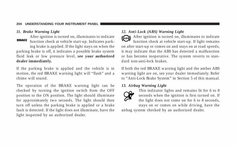
11. Brake Warning LightAfter ignition is turned on, illuminates to indicatefunction check at vehicle start-up. Indicates park-ing brake is applied. If the light stays on when the
parking brake is off, it indicates a possible brake systemfluid leak or low pressure level, see your authorizeddealer immediately.
If the parking brake is applied and the vehicle is inmotion, the red BRAKE warning light will “flash” and achime will sound.
The operation of the BRAKE warning light can bechecked by turning the ignition switch from the OFFposition to the ON position. The light should illuminatefor approximately two seconds. The light should thenturn off unless the parking brake is applied or a brakefault is detected. If the light does not illuminate, have thelight inspected by an authorized dealer.
12. Anti-Lock (ABS) Warning LightAfter ignition is turned on, illuminates to indicatefunction check at vehicle start-up. If light remains
on after start-up or comes on and stays on at road speeds,it may indicate that the ABS has detected a malfunctionor has become inoperative. The system reverts to stan-dard non-anti-lock brakes.
If both the red BRAKE warning light and the amber ABSwarning light are on, see your dealer immediately. Referto “Anti-Lock Brake System” in Section 5 of this manual.
13. Airbag Warning LightThis indicator lights and remains lit for 6 to 8seconds when the ignition is first turned on. Ifthe light does not come on for 6 to 8 seconds,stays on or comes on while driving, have the
airbag system checked by an authorized dealer.
204 UNDERSTANDING YOUR INSTRUMENT PANEL
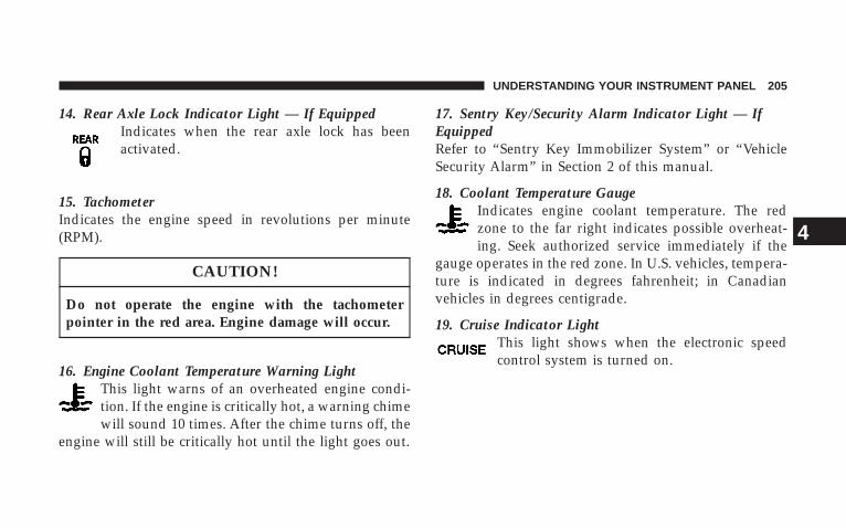
14. Rear Axle Lock Indicator Light — If EquippedIndicates when the rear axle lock has beenactivated.
15. TachometerIndicates the engine speed in revolutions per minute(RPM).
CAUTION!
Do not operate the engine with the tachometerpointer in the red area. Engine damage will occur.
16. Engine Coolant Temperature Warning LightThis light warns of an overheated engine condi-tion. If the engine is critically hot, a warning chimewill sound 10 times. After the chime turns off, the
engine will still be critically hot until the light goes out.
17. Sentry Key/Security Alarm Indicator Light — IfEquippedRefer to “Sentry Key Immobilizer System” or “VehicleSecurity Alarm” in Section 2 of this manual.
18. Coolant Temperature GaugeIndicates engine coolant temperature. The redzone to the far right indicates possible overheat-ing. Seek authorized service immediately if the
gauge operates in the red zone. In U.S. vehicles, tempera-ture is indicated in degrees fahrenheit; in Canadianvehicles in degrees centigrade.
19. Cruise Indicator LightThis light shows when the electronic speedcontrol system is turned on.
UNDERSTANDING YOUR INSTRUMENT PANEL 205
4
20. 4WD Indicator Light — If EquippedThis light alerts the driver that the vehicle is inthe four-wheel drive mode, and the front andrear driveshafts are mechanically locked to-gether forcing the front and rear wheels to
rotate at the same speed.
21. Odometer/Trip Odometer Reset ButtonPress this button to change the display from odometer toeither of the two trip odometer settings. Trip A or Trip Bwill appear when in the trip odometer mode. Push in andhold the button for two seconds to reset the trip odometerto 0 miles or kilometers. The odometer must be in tripmode to reset.
22. Transmission Range IndicatorThis display indicator shows the automatic transmissiongear selection.
23. Tire Pressure Monitoring Telltale Light — IfEquipped
Each tire, including the spare (if provided),should be checked monthly when cold andinflated to the inflation pressure recommendedby the vehicle manufacturer on the vehicle
placard or tire inflation pressure label. (If your vehiclehas tires of a different size than the size indicated on thevehicle placard or tire inflation pressure label, you shoulddetermine the proper tire inflation pressure for thosetires.)
As an added safety feature, your vehicle may beequipped with a tire pressure monitoring system (TPMS)that illuminates a low tire pressure telltale when one ormore of your tires is significantly under-inflated. Accord-ingly, when the low tire pressure telltale illuminates, youshould stop and check your tires as soon as possible, andinflate them to the proper pressure. Driving on a signifi-cantly under-inflated tire causes the tire to overheat and
206 UNDERSTANDING YOUR INSTRUMENT PANEL

can lead to tire failure. Under-inflation also reduces fuelefficiency and tire tread life, and may affect the vehicle’shandling and stopping ability.
Please note that the TPMS is not a substitute for propertire maintenance, and it is the driver’s responsibility tomaintain correct tire pressure, even if under-inflation hasnot reached the level to trigger illumination of the TPMSlow tire pressure telltale.
The “Tire Pressure Monitoring Telltale Light” will illumi-nate in the instrument cluster, and an audible chime willbe activated when one or more tire pressures is low. The“Tire Pressure Monitoring Telltale Light” will flash onand off for 60 seconds when a system fault is detected.The flash cycle will repeat every ten minutes or until thefault condition is removed and reset.
CAUTION!
The TPMS has been optimized for the originalequipment tires and wheels. TPMS pressures andwarnings have been established for the tire sizeequipped on your vehicle. Undesirable system opera-tion or sensor damage may result when using re-placement equipment that is not of the same size,type, and/or style. After-market wheels can causesensor damage. Do not use tire sealant from a can, orbalance beads if your vehicle is equipped with aTPMS, as damage to the sensors may result.
UNDERSTANDING YOUR INSTRUMENT PANEL 207
4
24. Odometer/Trip OdometerThe odometer shows the total distance the vehicle hasbeen driven.
U.S. federal regulations require that upon transfer ofvehicle ownership, the seller certify to the purchaser thecorrect mileage that the vehicle has been driven. There-fore, if the odometer reading is changed during repair orreplacement, be sure to keep a record of the readingbefore and after the service so the correct mileage can bedetermined.
25. Malfunction Indicator LightThis light is a part of an Onboard DiagnosticSystem called OBD II that monitors engine, andautomatic transmission control systems. The light
will illuminate when the ignition is in the ON positionbefore engine start. If the bulb does not come on whenturning the key from OFF to ON, have the conditionchecked promptly.
Certain conditions such as a loose or missing gas cap,poor quality fuel, etc. may illuminate the light afterengine start. The vehicle should be serviced if the lightstays on through several typical driving styles. In mostsituations, the vehicle will drive normally and will notrequire towing.
When the engine is running, the “Malfunction IndicatorLight” may flash to alert serious conditions that couldlead to immediate loss of power or severe catalyticconverter damage. The vehicle should be serviced assoon as possible if this occurs.
26. Electronic Stability Program (ESP) IndicatorLight/Traction Control System (TCS) Indicator Light
This indicator light starts to flash as soon as thetires lose traction and the ESP system becomesactive. The “ESP/TCS Indicator Light” alsoflashes when TCS is active. If the “ESP/TCS
Indicator Light” begins to flash during acceleration, ease
208 UNDERSTANDING YOUR INSTRUMENT PANEL
up on the accelerator and apply as little throttle aspossible. Be sure to adapt your speed and driving to theprevailing road conditions. The “ESP/TCS IndicatorLight” will flash any time the ESP or TCS is active andhelping to improve vehicle stability. If the “ESP/TCSIndicator Light” is on solid, the ESP system has beenturned off by the driver or a temporary condition existsthat will not allow full ESP function.
27. O/D (Overdrive) Off Indicator LightThis light will illuminate when the O/D OFFbutton has been selected. The O/D OFF button is
located on the gear shift lever.
28. Sway Bar Indicator Light — If EquippedThis light will illuminate when the front swaybar is disconnected.
29. Electronic Stability Program (ESP) WarningLight/Brake Assist System (BAS) Warning Light
The ESP/BAS warning light in the instrumentcluster comes on when the ignition switch isturned to the “ON” position. The light shouldgo out with the engine running. If the ESP/
BAS warning light comes on continuously with theengine running, a malfunction has been detected in eitherthe ESP or the BAS system. If this light stays illuminated,have the ESP and BAS checked at your authorized dealeras soon as possible. Refer to “Electronic Brake ControlSystem” in Section 5 for more information.
UNDERSTANDING YOUR INSTRUMENT PANEL 209
4
30. Electronic Throttle Control (ETC) Warning Light —If Equipped
This light informs you of a problem with theElectronic Throttle Control System. If a prob-lem is detected while the engine is running, thelight will either stay on or flash depending on
the nature of the problem. Cycle the ignition key whenthe vehicle is safely and completely stopped and the gearselector is placed in the P (Park) position. The lightshould turn off. If the light remains on with the enginerunning, your vehicle will usually be drivable, however,see your dealer for service as soon as possible.
If the light continues to flash when the engine is running,immediate service is required and you may experiencereduced performance, an elevated / rough idle, or enginestall and your vehicle may require towing. The light willcome on when the ignition is first turned on and remain
on briefly as a bulb check. If the light does not come onduring starting, have the system checked by an autho-rized dealer.
31. Compass/Mini-Trip Computer Display — IfEquippedWhen the appropriate conditions exist, this displayshows the Mini-Trip Computer messages. Refer to “Mini-Trip Computer” later in this section.
32. Compass/Mini-Trip Computer Button—If EquippedPress this button to switch between the different func-tions.
210 UNDERSTANDING YOUR INSTRUMENT PANEL
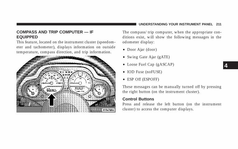
COMPASS AND TRIP COMPUTER — IFEQUIPPEDThis feature, located on the instrument cluster (speedom-eter and tachometer), displays information on outsidetemperature, compass direction, and trip information.
The compass/trip computer, when the appropriate con-ditions exist, will show the following messages in theodometer display:
• Door Ajar (door)
• Swing Gate Ajar (gATE)
• Loose Fuel Cap (gASCAP)
• IOD Fuse (noFUSE)
• ESP Off (ESPOFF)
These messages can be manually turned off by pressingthe right button (on the instrument cluster).
Control ButtonsPress and release the left button (on the instrumentcluster) to access the computer displays.
UNDERSTANDING YOUR INSTRUMENT PANEL 211
4
Press and hold the left button (on the instrument cluster)for 2 to 3 seconds to switch from English to Metricdisplays.
ResetPress and hold the right button (on the instrumentcluster) while function is being displayed to reset.
The following trip conditions can be reset:
• AVG ECO (changes to present fuel economy)
• ET
Trip Conditions
Average Fuel Economy (AVG ECO)This display shows the average fuel economy since thelast reset.
Estimated Range (DTE)This display shows the estimated distance that can betraveled with the fuel remaining in the tank. This esti-mated distance is based on the most recent trip informa-tion: (Average Fuel Economy) x (Fuel Remaining)
This display cannot be reset.
Elapsed Time (ET)This display shows the accumulated ignition ON timesince the last reset.
Trip Odometer (ODO)This display shows the distance traveled since the lastreset. Press and release the right button (on the instru-ment cluster) to switch from odometer, to trip A or trip B.Press and hold the right button while the odometer/tripodometer is displayed to reset.
212 UNDERSTANDING YOUR INSTRUMENT PANEL
Trip AShows the total distance traveled for trip A since the lastreset.
Trip BShows the total distance traveled for trip B since the lastreset.
Compass Temperature DisplayThis display provides the outside temperature and one ofeight compass readings to indicate the direction thevehicle is facing.
WARNING!
Even if the display still reads a few degrees above32°F ( 0°C), the road surface may be icy, particularlyin woods or on bridges. Drive carefully under suchconditions to prevent an accident and possible per-sonal injury or property damage.
Compass CalibrationThe Automatic Compass Calibration feature eliminatesthe need for the operator intervention under normalconditions. If the CAL indicator is lit, the compass needsto be calibrated. A good calibration requires a levelsurface and an environment free of large metal objectssuch as large buildings, bridges, underground cables,railroad tracks, etc.
Automatic Compass CalibrationThe self-calibrating feature of the compass eliminates theneed to calibrate the compass for normal conditions.During a short initial period, the compass may appearerratic and the CAL symbol will appear (blinking) on thedisplay. After the vehicle has completed at least onecomplete circle under 5 mph (8 km/h) in an area freefrom large metal objects, calibration will be completewhen the CAL symbol is extinguished.
UNDERSTANDING YOUR INSTRUMENT PANEL 213
4
After initial calibration, the compass will continue toautomatically update this calibration whenever the ve-hicle is in motion.
Manual Compass Calibration
NOTE: Before attempting a manual compass calibra-tion, the engine must be running and the transmissionin the P (Park) position (if equipped).
Compass calibration can also be requested. To manuallycalibrate the compass, you must first enter the variancemode. Press the and hold the left button (located on theinstrument cluster) for approximately 10 seconds to enterthe variance mode, and release the button when the VARsymbol appears. The current variance value will also bedisplayed. Once in the variance mode, it is necessary torelease the button, and then press and hold it again(approximately 10 seconds) until CAL is displayed (solidnot blinking). Manual compass calibration has beeninitiated. Drive the vehicle slowly in one or more circles
under 5 mph (8 km/h) in an area free from large metalobjects until the CAL symbol is extinguished.
When the CAL symbol no longer is displayed, thecompass is calibrated and should display correct head-ings. Verify proper calibration by checking North (N),South (S), East (E), and West (W). If the compass does notappear accurate, repeat the calibration procedure in an-other area.
Compass VarianceVariance is the difference between magnetic North andgeographic North. For proper compass function, thecorrect variance zone must be set.
Setting the Compass VarianceRefer to the variance map for the correct compass vari-ance zone. To check the variance zone, the ignition mustbe on. Press and hold the left button (located on theinstrument cluster) for approximately 10 seconds to enterthe variance mode and release the button when the VAR
214 UNDERSTANDING YOUR INSTRUMENT PANEL
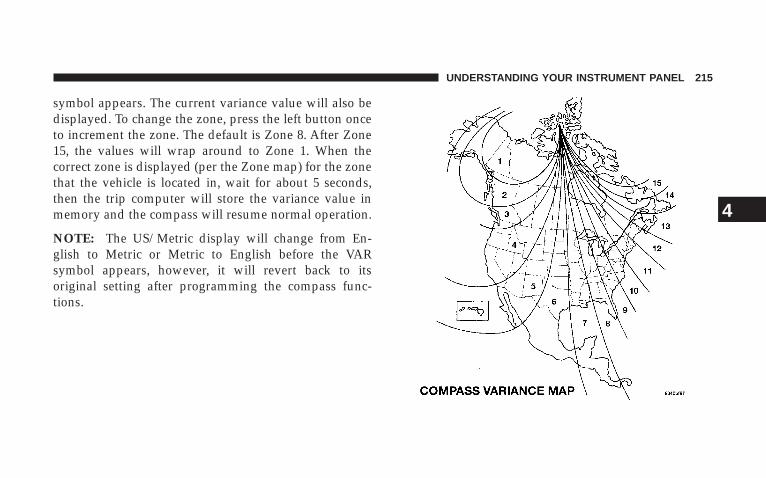
symbol appears. The current variance value will also bedisplayed. To change the zone, press the left button onceto increment the zone. The default is Zone 8. After Zone15, the values will wrap around to Zone 1. When thecorrect zone is displayed (per the Zone map) for the zonethat the vehicle is located in, wait for about 5 seconds,then the trip computer will store the variance value inmemory and the compass will resume normal operation.
NOTE: The US/Metric display will change from En-glish to Metric or Metric to English before the VARsymbol appears, however, it will revert back to itsoriginal setting after programming the compass func-tions.
UNDERSTANDING YOUR INSTRUMENT PANEL 215
4
Outside TemperatureIf the outside temperature is more than 131°F (55°C), thedisplay will show 131°F (55°C). When the outside tem-perature is less than �40°F (�40°C), the display willshow �40°F (�40°C).
RADIO GENERAL INFORMATION
Radio Broadcast SignalsYour new radio will provide excellent reception undermost operating conditions. Like any system, however, carradios have performance limitations, due to mobile op-eration and natural phenomena, which might lead you tobelieve your sound system is malfunctioning. To helpyou understand and save you concern about these “ap-parent” malfunctions, you must understand a point ortwo about the transmission and reception of radio sig-nals.
Two Types of SignalsThere are two basic types of radio signals... AM orAmplitude Modulation, in which the transmitted soundcauses the amplitude, or height, of the radio waves tovary... and FM or Frequency Modulation, in which thefrequency of the wave is varied to carry the sound.
Electrical DisturbancesRadio waves may pick up electrical disturbances duringtransmission. They mainly affect the wave amplitude,and thus remain a part of the AM reception. Theyinterfere very little with the frequency variations thatcarry the FM signal.
AM ReceptionAM sound is based on wave amplitude, so AM receptioncan be disrupted by such things as lightning, power linesand neon signs.
216 UNDERSTANDING YOUR INSTRUMENT PANEL
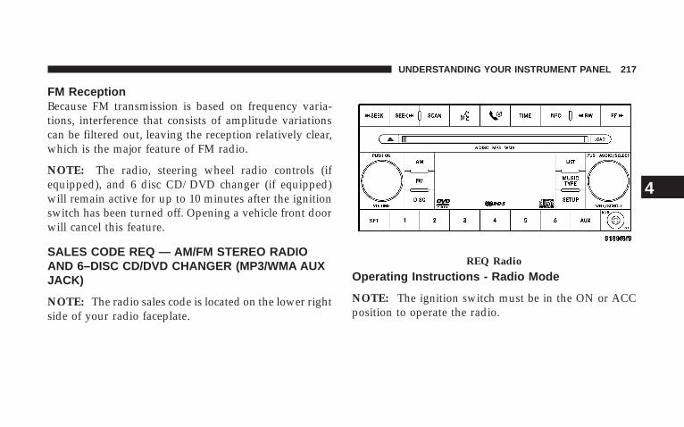
FM ReceptionBecause FM transmission is based on frequency varia-tions, interference that consists of amplitude variationscan be filtered out, leaving the reception relatively clear,which is the major feature of FM radio.
NOTE: The radio, steering wheel radio controls (ifequipped), and 6 disc CD/DVD changer (if equipped)will remain active for up to 10 minutes after the ignitionswitch has been turned off. Opening a vehicle front doorwill cancel this feature.
SALES CODE REQ — AM/FM STEREO RADIOAND 6–DISC CD/DVD CHANGER (MP3/WMA AUXJACK)
NOTE: The radio sales code is located on the lower rightside of your radio faceplate.
Operating Instructions - Radio Mode
NOTE: The ignition switch must be in the ON or ACCposition to operate the radio.
REQ Radio
UNDERSTANDING YOUR INSTRUMENT PANEL 217
4
Power Switch/Volume Control (Rotary)Press the ON/VOL control to turn the radio ON. Pressthe ON/VOL a second time to turn OFF the radio.
Electronic Volume ControlThe electronic volume control turns continuously (360degrees) in either direction without stopping. Turning thevolume control to the right increases the volume and tothe left decreases it.
When the audio system is turned on, the sound will beset at the same volume level as last played.
SEEK Buttons (Radio Mode)Press and release the SEEK buttons to search for the nextlistenable station in AM/FM mode. Press the right switchto seek up and the left switch to seek down. The radiowill remain tuned to the new station until you makeanother selection. Holding either button will bypassstations without stopping until you release it.
SCAN Button (Radio Mode)Pressing the SCAN button causes the tuner to search forthe next listenable station, in AM, FM or Satellite (ifequipped) frequencies, pausing for 5 seconds at eachlistenable station before continuing to the next. To stopthe search, press the SCAN button a second time.
Voice Recognition Button (UConnect™ Hands FreePhone) — If EquippedPress this button to operate the Hand Free Phone (UCon-nect™) feature (if equipped). Refer to Hands-Free Com-munication (UConnect™) in Section 3 for more informa-tion.
If your vehicle is not equipped with this feature, a“UConnect™ System Not Available” message will dis-play on the radio screen.
218 UNDERSTANDING YOUR INSTRUMENT PANEL

Phone Button (UConnect™ Hands Free Phone) —If EquippedPress this button to operate the Hand Free Phone (UCon-nect™) feature (if equipped). Refer to Hands-Free Com-munication (UConnect™) in Section 3 for more informa-tion.
If your vehicle is not equipped with this feature, a“UConnect™ System Not Available” message will dis-play on the radio screen.
TIME ButtonPress the TIME button and the time of day will display. InAM or FM mode, pressing the TIME button will switchbetween the time and frequency displays.
Clock Setting Procedure
1. Press and hold the TIME button, until the hours blink.
2. Adjust the hours by turning the right side TUNEcontrol knob.
3. After adjusting the hours, press the right side TUNEcontrol knob to set the minutes. The minutes will begin toblink.
4. Adjust the minutes using the right side TUNE controlknob. Press the TUNE control knob to save time change.
5. To exit, press any button/knob or wait 5 seconds.
The clock can also be set by pressing the SETUP buttonand selecting the “SET HOME CLOCK” entry. Once inthis display follow the above procedure, starting at step2.
INFO Button (Radio Mode)Press the INFO button for an RDS station (one with callletters displayed). The radio will return a Radio Textmessage broadcast from an FM station (FM mode only).
UNDERSTANDING YOUR INSTRUMENT PANEL 219
4
RW/FF (Radio Mode)Pressing the rewind or fast forward button causes thetuner to search for the next frequency in the direction ofthe arrows. This feature operates in either AM, FM orSatellite (if equipped) frequencies.
TUNE Control (Radio Mode)Turn the right side rotary control clockwise to increase orcounter-clockwise to decrease the frequency.
Setting the Tone, Balance, and FadePress the rotary TUNE control knob and BASS willdisplay. Turn the TUNE control knob to the right or left toincrease or decrease the Bass tones.
Press the rotary TUNE control knob a second time andMID will display. Turn the TUNE control knob to theright or left to increase or decrease the Mid Range tones.
Press the rotary TUNE control knob a third time andTREBLE will display. Turn the TUNE control knob to theright or left to increase or decrease the Treble tones.
Press the rotary TUNE control knob a fourth time andBALANCE will display. Turn the TUNE control knob tothe right or left to adjust the sound level from the right orleft side speakers.
Press the rotary TUNE control knob a fifth time andFADE will display. Turn the TUNE control knob to theleft or right to adjust the sound level between the frontand rear speakers.
Press the rotary TUNE control knob again to exit settingtone, balance, and fade.
MUSIC TYPE Button (Radio Mode)Pressing this button once will turn on the Music Typemode for 5 seconds. Pressing the Music Type button orturning the TUNE control knob within 5 seconds will
220 UNDERSTANDING YOUR INSTRUMENT PANEL
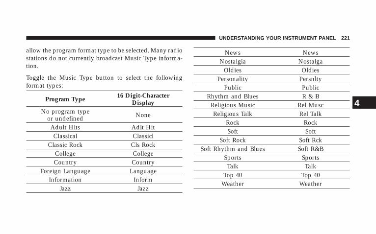
allow the program format type to be selected. Many radiostations do not currently broadcast Music Type informa-tion.
Toggle the Music Type button to select the followingformat types:
Program Type 16 Digit-CharacterDisplay
No program typeor undefined None
Adult Hits Adlt HitClassical Classicl
Classic Rock Cls RockCollege CollegeCountry Country
Foreign Language LanguageInformation Inform
Jazz Jazz
News NewsNostalgia Nostalga
Oldies OldiesPersonality Persnlty
Public PublicRhythm and Blues R & B
Religious Music Rel MuscReligious Talk Rel Talk
Rock RockSoft Soft
Soft Rock Soft RckSoft Rhythm and Blues Soft R&B
Sports SportsTalk Talk
Top 40 Top 40Weather Weather
UNDERSTANDING YOUR INSTRUMENT PANEL 221
4
By pressing the SEEK button when the Music Type iconis displayed, the radio will be tuned to the next frequencystation with the same selected Music Type name. TheMusic Type function only operates when in the FMmode.
If a preset button is activated while in the Music Type(Program Type) mode, the Music Type mode will beexited and the radio will tune to the preset station.
SETUP ButtonPressing the SETUP button allows you to select betweenthe following items:
NOTE: Use the Tune Control Knob to scroll through theentries. Push the Audio/Select button to select an entryand make changes.
• DVD Enter - When the disc is in DVD Menu mode,selecting DVD Enter will allow you to play the currenthighlighted selection. Use the remote control to scrollup and down the menu (If Equipped).
• DISC Play/Pause - You can toggle betweenplaying the DVD and pausing the DVD bypushing the SELECT button (If Equipped).
• DVD Play Options - Selecting the DVD Play Optionswill display the following:
• Subtitle – Repeatedly Pressing SELECT will switchsubtitles to different subtitle languages that areavailable on the disc (If Equipped).
• Audio Stream – Repeatedly Pressing SELECT willswitch to different audio languages (if supported onthe disc) (If Equipped).
222 UNDERSTANDING YOUR INSTRUMENT PANEL
• Angle – Repeatedly Pressing SELECT will changethe viewing angle if supported by the DVD disc (IfEquipped).
NOTE: The available selections for each of the aboveentries varies depending upon the disc.
NOTE: These selections can only be made while playinga DVD.
• VES Power - Allows you to turn VES ON and OFF (IfEquipped).
• VES Lock - Locks out rear VES remote controls (IfEquipped).
• VES CH1/CH2 - Allows the user to change mode ofeither the IR1 or IR2, wireless headphones, by pressingthe Audio/Select button (If Equipped).
• Set Home Clock - Pressing the SELECT button willallow user to set the clock. Turn the TUNE control
knob to adjust the hours and then press and turn theTUNE control knob to adjust the minutes. Press theTUNE control knob again to save changes.
• Player Defaults - Selecting this item will allow theuser to scroll through the following items, and setdefaults according to customer preference.
Menu Language — If Equipped
Selecting this item will allow the user to choose thedefault startup DVD menu language (effective only iflanguage supported by disc). If customer wishes to selecta language not listed, then scroll down and select �other.�Enter the 4-digit country code using the TUNE controlknob to scroll up and down to select the # and then pushto select.
Audio Language — If Equipped
Selecting this item will allow the user to choose a defaultaudio language (effective only if language supported by
UNDERSTANDING YOUR INSTRUMENT PANEL 223
4
disc). If customer wishes to select a language not listed,then scroll down and select �other.� Enter the countrycode using the TUNE control knob to scroll up and downto select the # and then push to select.
Subtitle Language — If Equipped
Selecting this item will allow the user to choose a defaultsubtitle language (effective only if language supportedby disc). If customer wishes to select a language notlisted, then scroll down and select �other.� Enter thecountry code using the TUNE control knob to scroll upand down to select the # and then push to select.
Subtitles — If Equipped
Selecting this item will allow the user to choose betweensubtitle OFF or ON.
Audio DRC — If Equipped
Selecting this item will allow the user to limit maximumaudio dynamic range - The default is set to �High,� andunder this setting, dialogues will play at 11 db higherthan if the setting is �Normal.�
Aspect Ratio — If Equipped
Selecting this item will allow the user to choose betweenwide screen, pan scan, and letter box.
AutoPlay — If Equipped
When this is set to ON and a DVD video is inserted, itwill bypass the DVD menu screen and automatically playthe movie. In some rare cases, the DVD player may notauto play the main title. In such cases, use the menubutton on the remote control to select desired title to play.
224 UNDERSTANDING YOUR INSTRUMENT PANEL
NOTE: The user will have to set these defaults beforeloading a disc. If changes are made to these settings aftera disc is loaded, changes will not be effective. Also, thedefaults are effective only if the disc supports thecustomer-preferred settings.
AM and FM Buttons (Radio Mode)Press the buttons to select AM or FM Modes.
SET Button (Radio Mode) — To Set thePush-Button MemoryWhen you are receiving a station that you wish tocommit to push-button memory, press the SET button.The symbol SET 1 will now show in the display window.Select the button (1-6) you wish to lock onto this stationand press and release that button. If a button is notselected within 5 seconds after pressing the SET button,the station will continue to play but will not be storedinto push-button memory.
You may add a second station to each push-button byrepeating the above procedure with this exception: Pressthe SET button twice and SET 2 will show in the displaywindow. Each button can be set for SET 1 and SET 2 inboth AM and FM. This allows a total of 12 AM, 12 FM,and 12 Satellite (if equipped) stations to be stored intopush-button memory. The stations stored in SET 2memory can be selected by pressing the push-buttontwice.
Every time a preset button is used, a correspondingbutton number will display.
Buttons 1 - 6 (Radio Mode)These buttons tune the Radio to the stations that youcommit to push-button memory {12 AM, 12 FM, and 12Satellite (if equipped) stations}.
DISC ButtonPressing the DISC button will allow you to switch fromAM/FM modes to Disc modes.
UNDERSTANDING YOUR INSTRUMENT PANEL 225
4

Operation Instructions - (DISC MODE for CD andMP3/WMA Audio Play, DVD-VIDEO)The radio DVD player and many DVD discs are coded bygeographic region. These region codes must match inorder for the disc to play. If the region code for the DVDdisc does not match the region code for the radio DVDplayer, it will not play the disc. Customers may take theirvehicle to an authorized dealer to change the region codeof the player a maximum of 5 times.
CAUTION!
The radio may shut down during extremely hotconditions. When this occurs, the radio will indicate“Disc Hot” and shut off until a safe temperature isreached. This shutdown is necessary to protect theoptics of the DVD player and other radio internalcomponents.
NOTE: The ignition switch must be in the ON or ACCposition to operate the radio.
LOAD Button — Loading Compact Disc(s)Press the LOAD button and the push-button with thecorresponding number (1-6) where the CD is beingloaded. The radio will display PLEASE WAIT andprompt when to INSERT DISC. After the radio displays�INSERT DISC,� insert the CD into the player.
Radio display will show �LOADING DISC� when the discis loading and “READING DISC” when the radio isreading the disc.
CAUTION!
• This CD player will accept 4 3/4 inch (12 cm) discsonly. The use of other sized discs may damage theCD player mechanism.
226 UNDERSTANDING YOUR INSTRUMENT PANEL
Eject Button — Ejecting Compact Disc(s)Press the eject button and the push-button withthe corresponding number (1-6) where the CDwas loaded and the disc will unload and moveto the entrance for easy removal. Radio display
will show �EJECTING DISC� when the disc is beingejected and prompt the user to remove the disc.
Press and hold the eject button for 5 seconds and all CDswill be ejected from the radio.
The disc can be ejected with the radio and ignition OFF.
SEEK Button (CD MODE)Press the right SEEK button for the next selection on theCD. Press the left SEEK button to return to the beginningof the current selection, or return to the beginning of theprevious selection if the CD is within the first second ofthe current selection. Pressing and holding the SEEKbutton will allow to scroll through tracks faster in CD,MP3/MWA modes.
SCAN Button (CD MODE)Press the Scan button to scan through each track on theCD currently playing.
TIME Button (CD MODE)Press this button to change the display from a large CDplaying time display to a small CD playing time display.
RW/FF (CD MODE)Press and hold FF (Fast Forward) and the CD player willbegin to fast forward until FF is released or RW oranother CD button is pressed. The RW (Reverse) buttonworks in a similar manner.
AM or FM Button (CD MODE)Switches the Radio to the Radio mode.
UNDERSTANDING YOUR INSTRUMENT PANEL 227
4
RND Button (Random Play Button) (CD MODE)Press this button while the CD is playing to activateRandom Play. This feature plays the selections on thecompact disc in random order to provide an interestingchange of pace.
Press the right SEEK button to move to the next ran-domly selected track.
Press the RND button a second time to stop Random Play.
Notes On Playing MP3/WMA FilesThe radio can play MP3/WMA files; however, acceptableMP3/WMA file recording media and formats are limited.When writing MP3/WMA files, pay attention to thefollowing restrictions.
Supported Media (Disc Types)The MP3/WMA file recording media supported by theradio are CDDA, CD-R, CD-RW, MP3,WMA, DVD Video,DVD-R, DVD-RW, DVD+R, DVD+RW, and CDDA+MP3.
Supported Medium Formats (File Systems)The medium formats supported by the radio are ISO 9660Level 1 and Level 2 and includes the Joliet extension.When reading discs recorded using formats other thanISO 9660 Level 1 and Level 2, the radio may fail to readfiles properly and may be unable to play the file nor-mally. UDF and Apple HFS formats are not supported.
The radio uses the following limits for file systems:
• Maximum number of directory levels: 8
• Maximum number of files: 255
• Maximum number of folders: 100
• Maximum number of characters in file/folder names:
• Level 1: 12 (including a separator �.� and a3-character extension)
• Level 2: 31 (including a separator �.� and a3-character extension)
228 UNDERSTANDING YOUR INSTRUMENT PANEL
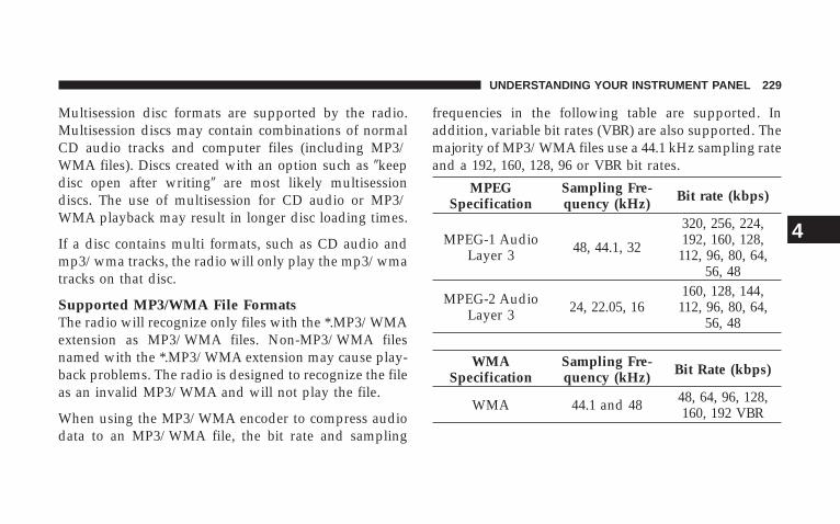
Multisession disc formats are supported by the radio.Multisession discs may contain combinations of normalCD audio tracks and computer files (including MP3/WMA files). Discs created with an option such as �keepdisc open after writing� are most likely multisessiondiscs. The use of multisession for CD audio or MP3/WMA playback may result in longer disc loading times.
If a disc contains multi formats, such as CD audio andmp3/wma tracks, the radio will only play the mp3/wmatracks on that disc.
Supported MP3/WMA File FormatsThe radio will recognize only files with the *.MP3/WMAextension as MP3/WMA files. Non-MP3/WMA filesnamed with the *.MP3/WMA extension may cause play-back problems. The radio is designed to recognize the fileas an invalid MP3/WMA and will not play the file.
When using the MP3/WMA encoder to compress audiodata to an MP3/WMA file, the bit rate and sampling
frequencies in the following table are supported. Inaddition, variable bit rates (VBR) are also supported. Themajority of MP3/WMA files use a 44.1 kHz sampling rateand a 192, 160, 128, 96 or VBR bit rates.
MPEGSpecification
Sampling Fre-quency (kHz) Bit rate (kbps)
MPEG-1 AudioLayer 3 48, 44.1, 32
320, 256, 224,192, 160, 128,
112, 96, 80, 64,56, 48
MPEG-2 AudioLayer 3 24, 22.05, 16
160, 128, 144,112, 96, 80, 64,
56, 48
WMASpecification
Sampling Fre-quency (kHz) Bit Rate (kbps)
WMA 44.1 and 48 48, 64, 96, 128,160, 192 VBR
UNDERSTANDING YOUR INSTRUMENT PANEL 229
4
ID3 Tag information for artist, song title, and album titleare supported for version 1 ID3 tags. ID3 version 2 is notsupported by the radios.
Playlist files are not supported. MP3 Pro files are notsupported.
Playback of MP3/WMA FilesWhen a medium containing MP3/WMA data is loaded,the radio checks all files on the medium. If the mediumcontains a lot of folders or files, the radio will take moretime to start playing the MP3/WMA files.
Loading times for playback of MP3/WMA files may beaffected by the following:
• Media - CD-RW media may take longer to load thanCD-R media
• Medium formats - Multisession discs may take longerto load than non-multisession discs
• Number of files and folders - Loading times willincrease with more files and folders
To increase the speed of disc loading, it is recommendedto use CD-R media and single-session discs. To create asingle-session disc, enable the Disc at Once option beforewriting to the disc.
LIST Button (DISC Mode for MP3/WMA Play)Pressing the LIST button will bring up a list of all folderson the disc. Scrolling up or down the list is done byturning the TUNE control knob. Selecting a folder bypressing the TUNE control knob will begin playing thefiles contained in that folder (or the next folder insequence if the selection does not contain playable files).
The folder list will time out after 5 seconds.
230 UNDERSTANDING YOUR INSTRUMENT PANEL
INFO Button (DISC Mode for MP3/WMA Play)Pressing the INFO button repeatedly will scroll throughthe following TAG information: Song Title, Artist, FileName, and Folder Name (if available).
Press the INFO button once more to return to �elapsedtime� priority mode.
Press and hold the INFO button for 3 seconds or moreand radio will display song titles for each file.
Press and hold the INFO button again for 3 seconds toreturn to �elapsed time� display.
Operation Instructions - Auxiliary ModeThe auxiliary (AUX) jack is an audio input jack, whichallows the user to plug in a portable device such as anMP3/WMA player, cassette player, or microphone andutilize the vehicle’s audio system to amplify the sourceand play through the vehicle speakers.
Pushing the AUX button will change the mode to auxil-iary device if the AUX jack is connected.
NOTE: The AUX device must be turned on and thedevice’s volume set to proper level. If the AUX audio isnot loud enough, turn the device’s volume up. If the AUXaudio sounds distorted, turn the device’s volume down.
SEEK Button (Auxiliary Mode)No function.
SCAN Button (Auxiliary Mode)No function.
EJECT Button (Auxiliary Mode)No function.
PSCAN Button (Auxiliary Mode)No function.
UNDERSTANDING YOUR INSTRUMENT PANEL 231
4
TIME Button (Auxiliary Mode)Press this button to change the display from elapsedplaying time to time of day. The time of day will displayfor 5 seconds.
RW/FF (Auxiliary Mode)No function.
SET Button (Auxiliary Mode)No function.
Operating Instructions - Hands Free Phone(UConnect™) (If Equipped)Refer to “Hands-Free Communication (UConnect™)” inSection 3 of this manual.
Operating Instructions - Satellite Radio Mode (IfEquipped)Refer to “Satellite Radio” in this section.
Operating Instructions - Video EntertainmentSystem (VES�) (If Equipped)Refer to separate Video Entertainment System (VES�) Guide.
DolbyManufactured under license from Dolby Laboratories.�Dolby� and the double-D symbol are trademarks ofDolby Laboratories.
MacrovisionThis product incorporates copyright protection technol-ogy that is protected by U.S. patents and other intellec-tual property rights. Use of this copyright protectiontechnology must be authorized by Macrovision, and isintended for home and other limited viewing uses onlyunless otherwise authorized by Macrovision. Reverseengineering or disassembly is prohibited
DTS�DTS� and �DTS 2.0� are trademarks of Digital TheaterSystems, Inc.
232 UNDERSTANDING YOUR INSTRUMENT PANEL
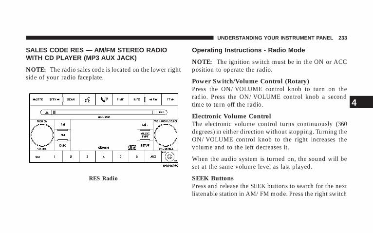
SALES CODE RES — AM/FM STEREO RADIOWITH CD PLAYER (MP3 AUX JACK)
NOTE: The radio sales code is located on the lower rightside of your radio faceplate.
Operating Instructions - Radio Mode
NOTE: The ignition switch must be in the ON or ACCposition to operate the radio.
Power Switch/Volume Control (Rotary)Press the ON/VOLUME control knob to turn on theradio. Press the ON/VOLUME control knob a secondtime to turn off the radio.
Electronic Volume ControlThe electronic volume control turns continuously (360degrees) in either direction without stopping. Turning theON/VOLUME control knob to the right increases thevolume and to the left decreases it.
When the audio system is turned on, the sound will beset at the same volume level as last played.
SEEK ButtonsPress and release the SEEK buttons to search for the nextlistenable station in AM/FM mode. Press the right switch
RES Radio
UNDERSTANDING YOUR INSTRUMENT PANEL 233
4
to seek up and the left switch to seek down. The radiowill remain tuned to the new station until you makeanother selection. Holding either button will bypassstations without stopping until you release it.
SCAN ButtonPressing the SCAN button causes the tuner to search forthe next listenable station in AM or FM frequencies,pausing for 5 seconds at each listenable station beforecontinuing to the next. To stop the search, press theSCAN button a second time.
Voice Recognition Button (UConnect™ Hands FreePhone) — If EquippedPress this button to operate the Hand Free Phone (UCon-nect™) feature (if equipped). Refer to Hands-Free Com-munication (UConnect™) in Section 3 for more informa-tion.
If your vehicle is not equipped with this feature, a“UConnect™ System Not Available” message will dis-play on the radio screen.
Phone Button (UConnect™ Hands Free Phone) —If EquippedPress this button to operate the Hand Free Phone (UCon-nect™) feature (if equipped). Refer to Hands-Free Com-munication (UConnect™) in Section 3 for more informa-tion.
If your vehicle is not equipped with this feature, a“UConnect™ System Not Available” message will dis-play on the radio screen.
TIME ButtonPress the TIME button and the time of day will display. InAM or FM mode, pressing the TIME button will switchbetween the time and frequency displays.
234 UNDERSTANDING YOUR INSTRUMENT PANEL
Clock Setting Procedure
1. Press and hold the TIME button, until the hours blink.
2. Adjust the hours by turning the right side TUNEcontrol knob.
3. After adjusting the hours, press the right side TUNEcontrol knob to set the minutes. The minutes will begin toblink.
4. Adjust the minutes using the right side TUNE controlknob. Press the TUNE control knob to save time change.
5. To exit, press any button/knob or wait 5 seconds.
The clock can also be set by pressing the SETUP button,and selecting SET CLOCK. Once in this display followthe above procedure, starting at step 2.
INFO ButtonPress the INFO button for an RDS station (one with callletters displayed). The radio will return a Radio Textmessage broadcast from an FM station (FM mode only).
RW/FFPressing the RW (Rewind) or FF (Fast Forward) buttonscauses the tuner to search for the next frequency in thedirection of the arrows. This feature operates in eitherAM or FM frequencies.
TUNE ControlTurn the right side rotary control clockwise to increase orcounter-clockwise to decrease the frequency.
Setting the Tone, Balance, and FadePress the rotary TUNE control knob and BASS willdisplay. Turn the TUNE control knob to the right or left toincrease or decrease the Bass tones.
UNDERSTANDING YOUR INSTRUMENT PANEL 235
4
Press the rotary TUNE control knob a second time andMID will display. Turn the TUNE control knob to theright or left to increase or decrease the Mid Range tones.
Press the rotary TUNE control knob a third time andTREBLE will display. Turn the TUNE control knob to theright or left to increase or decrease the Treble tones.
Press the rotary TUNE control knob a fourth time andBALANCE will display. Turn the TUNE control knob tothe right or left to adjust the sound level from the right orleft side speakers.
Press the rotary TUNE control knob a fifth time andFADE will display. Turn the TUNE control knob to theleft or right to adjust the sound level between the frontand rear speakers.
Press the rotary TUNE control knob again to exit settingtone, balance, and fade.
MUSIC TYPE ButtonPressing this button once will turn on the Music Type modefor 5 seconds. Pressing the Music Type button or turningthe TUNE control knob within 5 seconds will allow theprogram format type to be selected. Many radio stations donot currently broadcast Music Type information.
Toggle the Music Type button to select the followingformat types:
Program Type16 Digit-Character
DisplayNo program type
or undefined None
Adult Hits Adlt HitClassical Classicl
Classic Rock Cls RockCollege CollegeCountry Country
Foreign Language LanguageInformation Inform
236 UNDERSTANDING YOUR INSTRUMENT PANEL
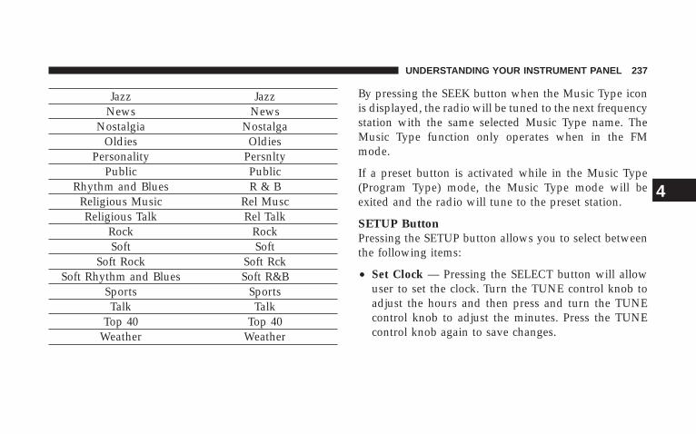
Jazz JazzNews News
Nostalgia NostalgaOldies Oldies
Personality PersnltyPublic Public
Rhythm and Blues R & BReligious Music Rel MuscReligious Talk Rel Talk
Rock RockSoft Soft
Soft Rock Soft RckSoft Rhythm and Blues Soft R&B
Sports SportsTalk Talk
Top 40 Top 40Weather Weather
By pressing the SEEK button when the Music Type iconis displayed, the radio will be tuned to the next frequencystation with the same selected Music Type name. TheMusic Type function only operates when in the FMmode.
If a preset button is activated while in the Music Type(Program Type) mode, the Music Type mode will beexited and the radio will tune to the preset station.
SETUP ButtonPressing the SETUP button allows you to select betweenthe following items:
• Set Clock — Pressing the SELECT button will allowuser to set the clock. Turn the TUNE control knob toadjust the hours and then press and turn the TUNEcontrol knob to adjust the minutes. Press the TUNEcontrol knob again to save changes.
UNDERSTANDING YOUR INSTRUMENT PANEL 237
4
AM and FM ButtonsPress the buttons to select AM or FM Modes.
SET Button — To Set the Push-Button MemoryWhen you are receiving a station that you wish tocommit to push-button memory, press the SET button.The symbol SET 1 will now show in the display window.Select the button (1-6) you wish to lock onto this stationand press and release that button. If a button is notselected within 5 seconds after pressing the SET button,the station will continue to play but will not be storedinto push-button memory.
You may add a second station to each push-button byrepeating the above procedure with this exception: Pressthe SET button twice and SET 2 will show in the displaywindow. Each button can be set for SET 1 and SET 2 inboth AM and FM. This allows a total of 12 AM and 12 FM
stations to be stored into push-button memory. Thestations stored in SET 2 memory can be selected bypressing the push-button twice.
Every time a preset button is used, a correspondingbutton number will display.
Buttons 1 - 6These buttons tune the radio to the stations that youcommit to push-button memory {12 AM and 12 FMstations}.
DISC ButtonPressing the DISC button will allow you to switch fromAM/FM modes to Disc modes.
238 UNDERSTANDING YOUR INSTRUMENT PANEL
Operation Instructions - CD MODE for CD andMP3 Audio Play
NOTE: The ignition switch must be in the ON or ACCposition to operate the radio.
NOTE: This Radio is capable of playing compact discs(CD), recordable compact discs (CD-R), rewritable com-pact discs (CD-RW) compact discs with MP3 tracks andmultisession compact discs with CD and MP3 tracks.
Inserting Compact Disc(s)Gently insert one CD into the CD player with the CDlabel facing up. The CD will automatically be pulled intothe CD player and the CD icon will illuminate on theradio display. If a CD does not go into the slot more thanan inch, a disc may already be loaded and must be ejectedbefore a new disc can be loaded.
If you insert a disc with the ignition ON and the radioON, the unit will switch from radio to CD mode and
begin to play when you insert the disc. The display willshow the disc number, the track number, and index timein minutes and seconds. Play will begin at the start oftrack 1.
CAUTION!
• This CD player will accept 4 3/4 inch (12 cm) discsonly. The use of other sized discs may damage theCD player mechanism.
• Do not use adhesive labels. These labels can peelaway and jam the player mechanism.
• RES is a single CD player. Do not attempt to inserta second CD if one is already loaded.
• Dual-media disc types (one side is a DVD, theother side is a CD) should not be used, and theycan cause damage to the player.
UNDERSTANDING YOUR INSTRUMENT PANEL 239
4
EJECT Button - Ejecting a CDPress the EJECT button to eject the CD.
If you have ejected a disc and have not removed it within10 seconds, it will be reloaded. If the CD is not removed,the radio will reinsert the CD but will not play it.
A disc can be ejected with the radio and ignition OFF.
NOTE: Ejecting with ignition OFF is not allowed onconvertible or soft-top models (if equipped).
SEEK ButtonPress the right SEEK button for the next selection on theCD. Press the left SEEK button to return to the beginningof the current selection, or return to the beginning of theprevious selection if the CD is within the first second of
the current selection. Pressing and holding the SEEKbutton will allow to scroll through tracks faster in CD,MP3 modes.
SCAN ButtonPress the Scan button to scan through each track on theCD currently playing.
TIME ButtonPress this button to change the display from a large CDplaying time display to a small CD playing time display.
RW/FFPress the RW button to stop the CD at the beginning ofthe current CD track/title.
Press and hold FF (Fast Forward) and the CD player willbegin to fast forward until FF is released or RW oranother CD button is pressed. The RW (Reverse) buttonworks in a similar manner.
240 UNDERSTANDING YOUR INSTRUMENT PANEL
AM or FM ButtonSwitches the Radio to the Radio mode.
RND Button (Random Play Button)Press this button while the CD is playing to activateRandom Play. This feature plays the selections on thecompact disc in random order to provide an interestingchange of pace.
Press the right SEEK button to move to the next ran-domly selected track.
Press the RND button a second time to stop RandomPlay.
Notes On Playing MP3 FilesThe radio can play MP3 files; however, acceptable MP3file recording media and formats are limited. Whenwriting MP3 files, pay attention to the following restric-tions.
Supported Media (Disc Types)The MP3 file recording media supported by the radio areCDDA, CD-R, CD-RW, MP3, and CDDA+MP3.
Supported Medium Formats (File Systems)The medium formats supported by the radio are ISO 9660Level 1 and Level 2 and includes the Joliet extension.When reading discs recorded using formats other thanISO 9660 Level 1 and Level 2, the radio may fail to readfiles properly and may be unable to play the file nor-mally. UDF and Apple HFS formats are not supported.
The radio uses the following limits for file systems:
• Maximum number of folder levels: 8
• Maximum number of files: 255
• Maximum number of folders (The radio display of filenames and folder names is limited. For large numbersof files and/or folders, the radio may be unable todisplay the file name and folder name and will assign
UNDERSTANDING YOUR INSTRUMENT PANEL 241
4
a number instead. With a maximum number of files,exceeding 20 folders will result in this display. With200 files, exceeding 50 folders will result in thisdisplay.
• Maximum number of characters in file/folder names:
• Level 1: 12 (including a separator �.� and a3-character extension)
• Level 2: 31 (including a separator �.� and a3-character extension)
Multisession disc formats are supported by the radio.Multisession discs may contain combinations of normalCD audio tracks and computer files (including MP3 files).Discs created with an option such as �keep disc open afterwriting� are most likely multisession discs. The use ofmultisession for CD audio or MP3 playback may result inlonger disc loading times.
Supported MP3 File FormatsThe radio will recognize only files with the *.MP3 exten-sion as MP3 files. Non-MP3 files named with the *.MP3extension may cause playback problems. The radio isdesigned to recognize the file as an invalid MP3 and willnot play the file.
When using the MP3 encoder to compress audio data toan MP3 file, the bit rate and sampling frequencies in thefollowing table are supported. In addition, variable bitrates (VBR) are also supported. The majority of MP3 filesuse a 44.1 kHz sampling rate and a 192, 160, 128, 96 orVBR bit rates.
242 UNDERSTANDING YOUR INSTRUMENT PANEL
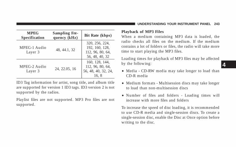
MPEGSpecification
Sampling Fre-quency (kHz) Bit Rate (kbps)
MPEG-1 AudioLayer 3 48, 44.1, 32
320, 256, 224,192, 160, 128,
112, 96, 80, 64,56, 48, 40, 32
MPEG-2 AudioLayer 3 24, 22.05, 16
160, 128, 144,112, 96, 80, 64,
56, 48, 40, 32, 24,16, 8
ID3 Tag information for artist, song title, and album titleare supported for version 1 ID3 tags. ID3 version 2 is notsupported by the radios.
Playlist files are not supported. MP3 Pro files are notsupported.
Playback of MP3 FilesWhen a medium containing MP3 data is loaded, theradio checks all files on the medium. If the mediumcontains a lot of folders or files, the radio will take moretime to start playing the MP3 files.
Loading times for playback of MP3 files may be affectedby the following:
• Media - CD-RW media may take longer to load thanCD-R media
• Medium formats - Multisession discs may take longerto load than non-multisession discs
• Number of files and folders - Loading times willincrease with more files and folders
To increase the speed of disc loading, it is recommendedto use CD-R media and single-session discs. To create asingle-session disc, enable the Disc at Once option beforewriting to the disc.
UNDERSTANDING YOUR INSTRUMENT PANEL 243
4
LIST Button (CD Mode for MP3 Play)Pressing the LIST button will bring up a list of all folderson the disc. Scrolling up or down the list is done byturning the TUNE control knob. Selecting a folder bypressing the TUNE control knob will begin playing thefiles contained in that folder (or the next folder insequence if the selection does not contain playable files).
The folder list will time out after 5 seconds.
INFO Button (CD Mode for MP3 Play)Pressing the INFO button repeatedly will scroll throughthe following TAG information: Song Title, Artist, FileName, and Folder Name (if available).
Press the INFO button once more to return to �elapsedtime� priority mode.
Press and hold the INFO button for 3 seconds or moreand radio will display song titles for each file.
Press and hold the INFO button again for 3 seconds toreturn to �elapsed time� display.
Operation Instructions - Auxiliary ModeThe auxiliary (AUX) jack is an audio input jack, whichallows the user to plug in a portable device such as anMP3 player, or cassette player, and utilize the vehicle’saudio system to amplify the source and play through thevehicle speakers.
Pushing the AUX button will change the mode to auxil-iary device if the AUX jack is connected.
NOTE: The AUX device must be turned on and thedevice’s volume set to proper level. If the AUX audio isnot loud enough, turn the device’s volume up. If the AUXaudio sounds distorted, turn the device’s volume down.
244 UNDERSTANDING YOUR INSTRUMENT PANEL
TIME Button (Auxiliary Mode)Press this button to change the display to time of day. Thetime of day will display for 5 seconds (when ignition isoff).
Operating Instructions - Hands Free Phone(UConnect™) (If Equipped)Refer to “Hands-Free Communication (UConnect™)” inSection 3 of this manual.
Operating Instructions - Satellite Radio Mode (IfEquipped)Refer to “Satellite Radio” in this section.
Operating Instructions - Video EntertainmentSystem (VES�) (If Equipped)Refer to separate Video Entertainment System (VES�)Guide.
SALES CODE RER — AM/FM/CD/DVD RADIOWITH NAVIGATION SYSTEM — IF EQUIPPED
NOTE: The radio sales code is located on the lower rightside of your radio faceplate.
Satellite Navigation Radio with CD Player with MP3Capability (RER) - combines a Global-PositioningSystem-based navigation system with an integrated colorscreen to provide maps, turn identification, selectionmenus, and instructions for selecting a variety of desti-nations and routes.
This radio has a hard drive. CD’s can be ripped to thehard drive, and the map data comes loaded on the harddrive. Refer to your “Navigation User’s Manual” fordetailed operating instructions.
UNDERSTANDING YOUR INSTRUMENT PANEL 245
4
Operating Instructions — Satellite RadioRefer to your “Navigation User’s Manual” for detailedoperating instructions.
Clock Setting ProcedureThe GPS receiver used in this system is synchronized tothe time data being transmitted by the GPS satellite. Thesatellites’ clock is Greenwich Mean Time (GMT). This isthe worldwide standard for time. This makes the sys-tem’s clock very accurate once the appropriate time zoneand daylight savings information is set.
To manually set the clock, change the time zone, orchange daylight savings information, use a ballpoint penor similar object to press the hour (H) or minute (M)buttons on the radio. The Setup screen appears.
Setting the Clock
1. Turn the ignition switch to the ON or ACC position.Using the tip of a ballpoint pen or similar object, press
either the H button on the faceplate to change the hour orthe M button on the faceplate to change the minute.
2. The time setting will increase each time you press thebutton. Holding either button in will fast forward thesetting.
3. If no changes are made within 5 seconds of accessingthe Setup screen, the screen will time out and you will betaken to the last mode.
NOTE: To reset the clock, select the appropriate timezone and press ENTER. The clock will revert to theaccurate time based on the time zone you selected.
Changing the Time Zone
1. Highlight “Clock Setup” and press ENTER.
2. At the Clock Setup screen highlight the box next to“Time Zone” and press ENTER.
246 UNDERSTANDING YOUR INSTRUMENT PANEL
3. Highlight the appropriate time zone for you locationand press ENTER to store your selection. Select “Done”when finished.
NOTE: When you are traveling and enter a new timezone, the clock must be reset manually for the new zone.
Changing Daylight Savings Time
1. Highlight the box next to “Time” and press ENTER.
2. Select Daylight Savings when Daylight Savings Timeis in effect or Select Standard if Daylight Savings Time isnot being observed. Press ENTER.
3. Select “Done” when finished.
Select “Done” to exit from the clock setting mode.
SATELLITE RADIO — IF EQUIPPEDSatellite radio uses direct satellite to receiver broadcast-ing technology to provide clear digital sound, coast tocoast. The subscription service provider is Sirius™ Satel-lite Radio. This service offers up to 100 channels of music,sports, news, entertainment, and programming for chil-dren, directly from its satellites and broadcasting studios.
System ActivationSirius Satellite Radio service is pre-activated, and youmay begin listening immediately to the one year ofSIRIUS audio service that is included with the factory-installed satellite radio system in your vehicle. Sirius willcontact you to supply a welcome kit and to confirmsubscription information, including the set up of youron-line listening account at no additional charge. Forfurther information, call the toll-free number 888-539-7474, or visit the Sirius web site at www.sirius.com.Please have the following information available whencalling:
UNDERSTANDING YOUR INSTRUMENT PANEL 247
4
1. The Electronic Serial Number/Sirius IdentificationNumber (ESN/SID).
2. Your Vehicle Identification Number.
Electronic Serial Number/Sirius IdentificationNumber (ENS/SID)The Electronic Serial Number/Sirius Identification Num-ber is needed to activate your Sirius Satellite Radiosystem. To access the ESN/SID, refer to the followingsteps:
ESN/SID Access With RSC RadiosWith the ignition switch in the ON/RUN or ACCESSORYposition and the radio ON, press the SETUP button andscroll using the TUNE control knob until Sirius ID isselected. Press the TUNE control knob and the Sirius IDnumber will display. The Sirius ID number display willtime out in 2 minutes. Press any button on the radio toexit this screen.
Selecting Satellite Mode (RSC Radios)Press the SAT button until �SAT� appears in the display. ACD may remain in the radio while in the Satellite radiomode.
Satellite AntennaTo ensure optimum reception, do not place items on theroof around the rooftop antenna location or strap items tothe trunk lid around the trunk lid antenna (if equipped).Metal objects placed within the line of sight of theantenna will cause decreased performance. Larger lug-gage items such as bikes should be placed as far rearwardas possible, within the loading design of the rack. Do notplace items directly on or above the antenna.
Reception QualitySatellite reception may be interrupted due to one of thefollowing reasons:
• The vehicle is parked in an underground parkingstructure or under a physical obstacle.
248 UNDERSTANDING YOUR INSTRUMENT PANEL
• Dense tree coverage may interrupt reception in theform of short audio mutes.
• Driving under wide bridges or along tall buildings cancause intermittent reception.
• Placing objects over or too close to the antenna cancause signal blockage.
Operating Instructions - Satellite Mode
NOTE: The ignition switch must be in the ON or ACCposition to operate the radio.
SEEK ButtonsPress and release the SEEK buttons to search for the nextchannel in Satellite mode. Press the right switch to seekup and the left switch to seek down. The radio willremain tuned to the new channel until you make anotherselection. Holding either button will bypass channelswithout stopping until you release it.
SCAN ButtonPressing the SCAN button causes the tuner to search forthe next channel, pausing for 8 seconds before continuingto the next. To stop the search, press the SCAN button asecond time.
INFO ButtonPressing the INFO button will cycle between Artist, SongTitle, and Composer (if available) information. Also,pressing and holding the INFO button for an additional3 seconds will make the radio display the Song Title all ofthe time (press and hold again to return to normaldisplay).
RW/FFPressing the RW (Rewind) or FF (Fast Forward) buttonscauses the tuner to search for the next channel in thedirection of the arrows.
UNDERSTANDING YOUR INSTRUMENT PANEL 249
4
TUNE Control (Rotary)Turn the right side rotary control clockwise to increase orcounter-clockwise to decrease the channel.
MUSIC TYPE ButtonPressing this button once will turn on the Music Typemode for 5 seconds. Pressing the MUSIC TYPE button orturning the TUNE control knob within 5 seconds willallow the program format type to be selected.
Toggle the MUSIC TYPE button again to select the musictype.
By pressing the SEEK button when the Music Typefunction is active, the radio will be tuned to the nextchannel with the same selected Music Type name.
If a preset button is activated while in the Music Type(Program Type) mode, the Music Type mode will beexited and the radio will tune to the preset channel.
SETUP ButtonPressing the SETUP button allows you to select thefollowing items:
• Display Sirius ID number — Press the SELECT buttonto display the Sirius ID number. This number is usedto activate, deactivate, or change the Sirius subscrip-tion.
SET Button — To Set the Push-Button MemoryWhen you are receiving a channel that you wish tocommit to push-button memory, press the SET button.The symbol SET 1 will now show in the display window.Select the button (1-6) you wish to lock onto this channeland press and release that button. If a button is notselected within 5 seconds after pressing the SET button,the channel will continue to play but will not be storedinto push-button memory.
You may add a second channel to each push-button byrepeating the above procedure with this exception: Press
250 UNDERSTANDING YOUR INSTRUMENT PANEL
the SET button twice and SET 2 will show in the displaywindow. Each button can be set for SET 1 and SET 2. Thisallows a total of 12 Satellite channels to be stored intopush-button memory. The channels stored in SET 2memory can be selected by pressing the push-buttontwice.
Every time a preset button is used, a correspondingbutton number will display.
Buttons 1 - 6These buttons tune the radio to the channels that youcommit to push-button memory {12 Satellite stations}.
Operating Instructions - Hands Free Phone (IfEquipped)Refer to Hands Free Phone in Section 3 of the Owner’sManual.
Operating Instructions - Video EntertainmentSystem (VES�) (If Equipped)Refer to separate Video Entertainment System (VES�) Guide.
CD/DVD DISC MAINTENANCETo keep the CD/DVD discs in good condition, take thefollowing precautions:
1. Handle the disc by its edge; avoid touching thesurface.
2. If the disc is stained, clean the surface with a soft cloth,wiping from center to edge.
3. Do not apply paper, paper CD labels, or tape to thedisc; avoid scratching the disc.
4. Do not use solvents such as benzine, thinner, cleaners,or antistatic sprays.
5. Store the disc in its case after playing.
UNDERSTANDING YOUR INSTRUMENT PANEL 251
4
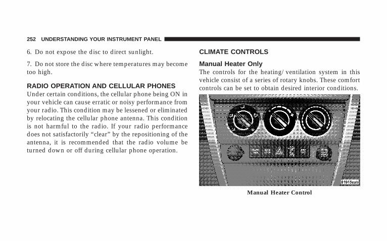
6. Do not expose the disc to direct sunlight.
7. Do not store the disc where temperatures may becometoo high.
RADIO OPERATION AND CELLULAR PHONESUnder certain conditions, the cellular phone being ON inyour vehicle can cause erratic or noisy performance fromyour radio. This condition may be lessened or eliminatedby relocating the cellular phone antenna. This conditionis not harmful to the radio. If your radio performancedoes not satisfactorily “clear” by the repositioning of theantenna, it is recommended that the radio volume beturned down or off during cellular phone operation.
CLIMATE CONTROLS
Manual Heater OnlyThe controls for the heating/ventilation system in thisvehicle consist of a series of rotary knobs. These comfortcontrols can be set to obtain desired interior conditions.
Manual Heater Control
252 UNDERSTANDING YOUR INSTRUMENT PANEL
Mode ControlThe mode control (left rotary knob) allows you to choosefrom several patterns of air distribution. You can selecteither a primary mode, as identified by the symbols, or ablend of two of these modes. The closer the control is toa particular mode, the more air distribution you receivefrom that mode.
PanelAir is directed through the outlets in the instrumentpanel. These outlets can be adjusted to direct air
flow.
Bi-LevelAir is directed through the panel and floor outlets.
NOTE: There is a difference in temperature between theupper and lower outlets for added comfort. The warmerair goes to the floor outlets. This feature gives improvedcomfort during sunny but cool conditions.
FloorAir is directed through the floor outlets and sidewindow demist outlets with a small amount
through the defrost outlet.
MixAir is directed through the floor, defrost and sidewindow demist outlets. This setting works best incold or snowy conditions that require extra heat at
the windshield. This setting is good for maintainingcomfort while reducing moisture on the windshield.
DefrostAir is directed through the windshield and sidewindow demist outlets. Use this mode with maxi-
mum fan and temperature settings for best windshieldand side window defrosting.
Blower ControlUse this control (center rotary knob) to regulate theamount of air forced through the system in any mode
UNDERSTANDING YOUR INSTRUMENT PANEL 253
4
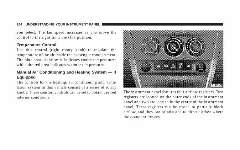
you select. The fan speed increases as you move thecontrol to the right from the OFF position.
Temperature ControlUse this control (right rotary knob) to regulate thetemperature of the air inside the passenger compartment.The blue area of the scale indicates cooler temperatureswhile the red area indicates warmer temperatures.
Manual Air Conditioning and Heating System — IfEquippedThe controls for the heating/air conditioning and venti-lation system in this vehicle consist of a series of rotaryknobs. These comfort controls can be set to obtain desiredinterior conditions.
The instrument panel features four airflow registers. Tworegisters are located on the outer ends of the instrumentpanel and two are located in the center of the instrumentpanel. These registers can be closed to partially blockairflow, and they can be adjusted to direct airflow wherethe occupant desires.
254 UNDERSTANDING YOUR INSTRUMENT PANEL
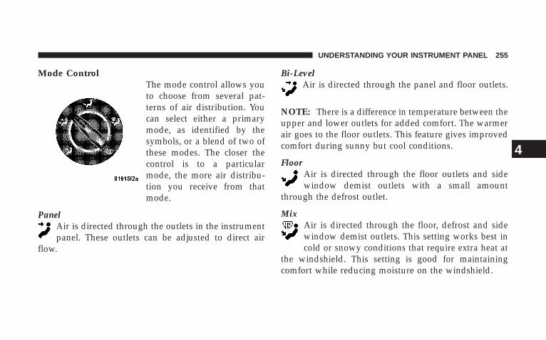
Mode ControlThe mode control allows youto choose from several pat-terns of air distribution. Youcan select either a primarymode, as identified by thesymbols, or a blend of two ofthese modes. The closer thecontrol is to a particularmode, the more air distribu-tion you receive from thatmode.
PanelAir is directed through the outlets in the instrumentpanel. These outlets can be adjusted to direct air
flow.
Bi-LevelAir is directed through the panel and floor outlets.
NOTE: There is a difference in temperature between theupper and lower outlets for added comfort. The warmerair goes to the floor outlets. This feature gives improvedcomfort during sunny but cool conditions.
FloorAir is directed through the floor outlets and sidewindow demist outlets with a small amount
through the defrost outlet.
MixAir is directed through the floor, defrost and sidewindow demist outlets. This setting works best incold or snowy conditions that require extra heat at
the windshield. This setting is good for maintainingcomfort while reducing moisture on the windshield.
UNDERSTANDING YOUR INSTRUMENT PANEL 255
4
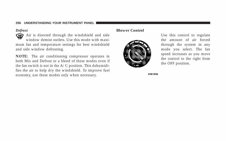
DefrostAir is directed through the windshield and sidewindow demist outlets. Use this mode with maxi-
mum fan and temperature settings for best windshieldand side window defrosting.
NOTE: The air conditioning compressor operates inboth Mix and Defrost or a blend of these modes even ifthe fan switch is not in the A/C position. This dehumidi-fies the air to help dry the windshield. To improve fueleconomy, use these modes only when necessary.
Blower ControlUse this control to regulatethe amount of air forcedthrough the system in anymode you select. The fanspeed increases as you movethe control to the right fromthe OFF position.
256 UNDERSTANDING YOUR INSTRUMENT PANEL
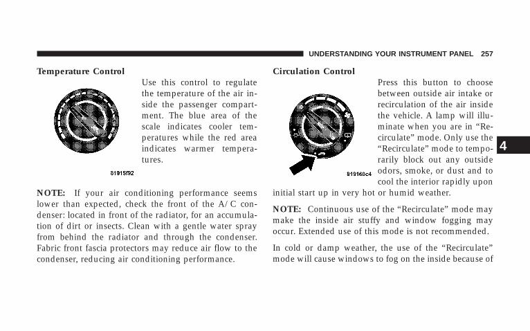
Temperature ControlUse this control to regulatethe temperature of the air in-side the passenger compart-ment. The blue area of thescale indicates cooler tem-peratures while the red areaindicates warmer tempera-tures.
NOTE: If your air conditioning performance seemslower than expected, check the front of the A/C con-denser: located in front of the radiator, for an accumula-tion of dirt or insects. Clean with a gentle water sprayfrom behind the radiator and through the condenser.Fabric front fascia protectors may reduce air flow to thecondenser, reducing air conditioning performance.
Circulation ControlPress this button to choosebetween outside air intake orrecirculation of the air insidethe vehicle. A lamp will illu-minate when you are in “Re-circulate” mode. Only use the“Recirculate” mode to tempo-rarily block out any outsideodors, smoke, or dust and tocool the interior rapidly upon
initial start up in very hot or humid weather.
NOTE: Continuous use of the “Recirculate” mode maymake the inside air stuffy and window fogging mayoccur. Extended use of this mode is not recommended.
In cold or damp weather, the use of the “Recirculate”mode will cause windows to fog on the inside because of
UNDERSTANDING YOUR INSTRUMENT PANEL 257
4
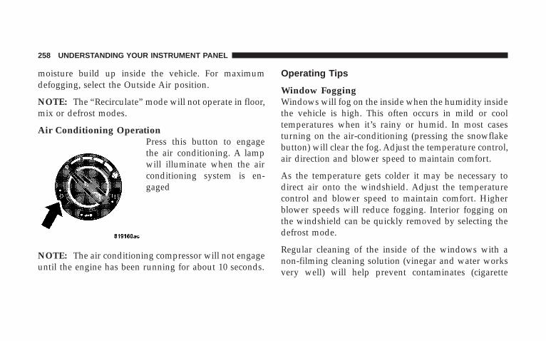
moisture build up inside the vehicle. For maximumdefogging, select the Outside Air position.
NOTE: The “Recirculate” mode will not operate in floor,mix or defrost modes.
Air Conditioning OperationPress this button to engagethe air conditioning. A lampwill illuminate when the airconditioning system is en-gaged
NOTE: The air conditioning compressor will not engageuntil the engine has been running for about 10 seconds.
Operating Tips
Window FoggingWindows will fog on the inside when the humidity insidethe vehicle is high. This often occurs in mild or cooltemperatures when it’s rainy or humid. In most casesturning on the air-conditioning (pressing the snowflakebutton) will clear the fog. Adjust the temperature control,air direction and blower speed to maintain comfort.
As the temperature gets colder it may be necessary todirect air onto the windshield. Adjust the temperaturecontrol and blower speed to maintain comfort. Higherblower speeds will reduce fogging. Interior fogging onthe windshield can be quickly removed by selecting thedefrost mode.
Regular cleaning of the inside of the windows with anon-filming cleaning solution (vinegar and water worksvery well) will help prevent contaminates (cigarette
258 UNDERSTANDING YOUR INSTRUMENT PANEL
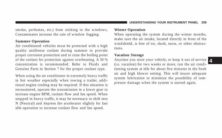
smoke, perfumes, etc.) from sticking to the windows.Contaminates increase the rate of window fogging.
Summer OperationAir conditioned vehicles must be protected with a highquality antifreeze coolant during summer to provideproper corrosion protection and to raise the boiling pointof the coolant for protection against overheating. A 50 %concentration is recommended. Refer to Fluids andGenuine Parts in Section 7 for the proper coolant type.
When using the air conditioner in extremely heavy trafficin hot weather especially when towing a trailer, addi-tional engine cooling may be required. If this situation isencountered, operate the transmission in a lower gear toincrease engine RPM, coolant flow and fan speed. Whenstopped in heavy traffic, it may be necessary to shift intoN (Neutral) and depress the accelerator slightly for fastidle operation to increase coolant flow and fan speed.
Winter OperationWhen operating the system during the winter months,make sure the air intake, located directly in front of thewindshield, is free of ice, slush, snow, or other obstruc-tions.
Vacation StorageAnytime you store your vehicle, or keep it out of service(i.e. vacation) for two weeks or more, run the air condi-tioning system at idle for about five minutes in the freshair and high blower setting. This will insure adequatesystem lubrication to minimize the possibility of com-pressor damage when the system is started again.
UNDERSTANDING YOUR INSTRUMENT PANEL 259
4

STARTING AND OPERATING
CONTENTS
� Starting Procedures . . . . . . . . . . . . . . . . . . . . . 265
▫ Manual Transmission . . . . . . . . . . . . . . . . . . 265
▫ Automatic Transmission . . . . . . . . . . . . . . . . 265
▫ Normal Starting . . . . . . . . . . . . . . . . . . . . . . 265
▫ Extreme Cold Weather(Below –20°F Or –29°C) . . . . . . . . . . . . . . . . . 266
▫ If Engine Fails To Start . . . . . . . . . . . . . . . . . 266
▫ After Starting . . . . . . . . . . . . . . . . . . . . . . . . 268
� Engine Block Heater — If Equipped . . . . . . . . . 269
� Manual Transmission . . . . . . . . . . . . . . . . . . . . 269
▫ 6-Speed Manual Transmission . . . . . . . . . . . . 269
� Automatic Transmission . . . . . . . . . . . . . . . . . . 273
▫ Shift Lock Manual Override . . . . . . . . . . . . . . 274
▫ Brake/Transmission Interlock System . . . . . . . 275
▫ Automatic Transmission With Overdrive . . . . . 275
� Four–Wheel Drive Operation (Command-Trac™Or Rock-Trac™) — If Equipped . . . . . . . . . . . . . 280
▫ Operating Instructions/Precautions . . . . . . . . . 280
5
▫ Shift Positions . . . . . . . . . . . . . . . . . . . . . . . . 282
▫ Shifting Procedure . . . . . . . . . . . . . . . . . . . . 283
� Trac-Lok™ Rear Axle — If Equipped . . . . . . . . . 284
� Axle Lock (Tru–Lok™) — Rubicon Models . . . . . 285
� Rear Axle Lock — 4WD Non-Rubicon Models(If Equipped) . . . . . . . . . . . . . . . . . . . . . . . . . . 286
� Electronic Sway Bar Disconnect — If Equipped . . 287
� On-Road Driving Tips . . . . . . . . . . . . . . . . . . . 289
� Off-Road Driving Tips . . . . . . . . . . . . . . . . . . . 290
▫ When To Use 4L (Low) Range . . . . . . . . . . . . 290
▫ Driving Through Water . . . . . . . . . . . . . . . . . 291
▫ Driving In Snow, Mud And Sand . . . . . . . . . . 292
▫ Hill Climbing . . . . . . . . . . . . . . . . . . . . . . . . 292
▫ Traction Downhill . . . . . . . . . . . . . . . . . . . . . 293
▫ After Driving Off-Road . . . . . . . . . . . . . . . . . 294
� Parking Brake . . . . . . . . . . . . . . . . . . . . . . . . . 295
� Anti-Lock Brake System . . . . . . . . . . . . . . . . . . 296
� Power Steering . . . . . . . . . . . . . . . . . . . . . . . . 298
� Tire Safety Information . . . . . . . . . . . . . . . . . . . 300
▫ Tire Markings . . . . . . . . . . . . . . . . . . . . . . . . 300
▫ Tire Identification Number (TIN) . . . . . . . . . . 303
▫ Tire Loading And Tire Pressure . . . . . . . . . . . 304
� Tires — General Information . . . . . . . . . . . . . . . 308
▫ Tire Pressure . . . . . . . . . . . . . . . . . . . . . . . . . 308
▫ Tire Inflation Pressures . . . . . . . . . . . . . . . . . 309
▫ Tire Pressures For High Speed Operation . . . . 311
262 STARTING AND OPERATING
▫ Radial-Ply Tires . . . . . . . . . . . . . . . . . . . . . . 312
▫ Tire Spinning . . . . . . . . . . . . . . . . . . . . . . . . 312
▫ Tread Wear Indicators . . . . . . . . . . . . . . . . . . 312
▫ Life Of Tire . . . . . . . . . . . . . . . . . . . . . . . . . 313
▫ Replacement Tires . . . . . . . . . . . . . . . . . . . . . 314
▫ Alignment And Balance . . . . . . . . . . . . . . . . . 315
� Tire Chains . . . . . . . . . . . . . . . . . . . . . . . . . . . 315
� Tire Rotation Recommendations . . . . . . . . . . . . 316
� Tire Pressure Monitor System (TPMS) — IfEquipped . . . . . . . . . . . . . . . . . . . . . . . . . . . . 317
▫ Base System — If Equipped . . . . . . . . . . . . . . 318
▫ General Information . . . . . . . . . . . . . . . . . . . 321
� Fuel Requirements . . . . . . . . . . . . . . . . . . . . . . 321
▫ Reformulated Gasoline . . . . . . . . . . . . . . . . . 322
▫ Gasoline/Oxygenate Blends . . . . . . . . . . . . . . 322
▫ MMT In Gasoline . . . . . . . . . . . . . . . . . . . . . 323
▫ Materials Added To Fuel . . . . . . . . . . . . . . . . 323
▫ Fuel System Cautions . . . . . . . . . . . . . . . . . . 324
▫ Carbon Monoxide Warnings . . . . . . . . . . . . . . 324
� Adding Fuel . . . . . . . . . . . . . . . . . . . . . . . . . . 325
▫ Fuel Filler Cap (Gas Cap) . . . . . . . . . . . . . . . 325
� Vehicle Loading . . . . . . . . . . . . . . . . . . . . . . . . 328
▫ Certification Label . . . . . . . . . . . . . . . . . . . . . 328
� Trailer Towing . . . . . . . . . . . . . . . . . . . . . . . . . 330
▫ Common Towing Definitions . . . . . . . . . . . . . 330
▫ Trailer Hitch Classification . . . . . . . . . . . . . . . 334
STARTING AND OPERATING 263
5
▫ Trailer Towing Weights (Maximum TrailerWeight Ratings) . . . . . . . . . . . . . . . . . . . . . . 335
▫ Trailer And Tongue Weight . . . . . . . . . . . . . . 338
▫ Towing Requirements . . . . . . . . . . . . . . . . . . 339
▫ Towing Tips . . . . . . . . . . . . . . . . . . . . . . . . . 344
� Recreational Towing (Behind Motorhome, Etc.) . . 346
▫ Towing – 2WD Models . . . . . . . . . . . . . . . . . 346
▫ Towing – 4WD Models . . . . . . . . . . . . . . . . . 346
▫ Shifting Out Of Neutral (N) . . . . . . . . . . . . . . 347
264 STARTING AND OPERATING
STARTING PROCEDURESBefore starting your vehicle, adjust your seat, adjust bothinside and outside mirrors, and fasten your seat belts.
WARNING!
Never leave children alone in a vehicle. Leavingchildren in a vehicle unattended is dangerous for anumber of reasons. A child or others could be seri-ously or fatally injured. Do not leave the keys in theignition. A child could operate power windows,other controls, or move the vehicle.
Manual TransmissionApply the parking brake, place the gearshift control leverin N (Neutral) and depress the clutch pedal beforestarting vehicle. This vehicle is equipped with a clutchinterlocking ignition system. It will not start unless theclutch pedal is pressed to the floor.
4WD Models OnlyIn 4L mode, this vehicle will start regardless of whetheror not the clutch pedal is pressed to the floor. This featureenhances off-road performance by allowing the vehicle tostart when in 4L without having to depress the clutchpedal. The “4WD Indicator Light” will illuminate whenthe transfer case has been shifted into this mode.
Automatic TransmissionStart the engine with the selector lever in the N (Neutral)or P (Park) position. Apply the brake before shifting toany driving range.
Normal StartingNormal starting of either a cold or a warm engine isobtained without pumping or depressing the acceleratorpedal. Turn the key to the START position and releasewhen the engine starts. If the engine fails to start within10 seconds, turn the key to the OFF position, wait 5seconds, then repeat the normal starting procedure.
STARTING AND OPERATING 265
5
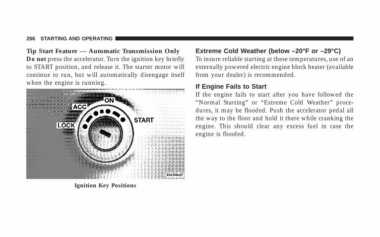
Tip Start Feature — Automatic Transmission OnlyDo not press the accelerator. Turn the ignition key brieflyto START position, and release it. The starter motor willcontinue to run, but will automatically disengage itselfwhen the engine is running.
Extreme Cold Weather (below –20°F or –29°C)To insure reliable starting at these temperatures, use of anexternally powered electric engine block heater (availablefrom your dealer) is recommended.
If Engine Fails to StartIf the engine fails to start after you have followed the“Normal Starting” or “Extreme Cold Weather” proce-dures, it may be flooded. Push the accelerator pedal allthe way to the floor and hold it there while cranking theengine. This should clear any excess fuel in case theengine is flooded.
Ignition Key Positions
266 STARTING AND OPERATING
CAUTION!
To prevent damage to the starter, do not crank theengine for more than 15 seconds at a time. Wait 10 to15 seconds before trying again.
WARNING!
Never pour fuel or other flammable liquids into thethrottle body air inlet opening in an attempt to startthe vehicle. This could result in a flash fire causingserious personal injury.
WARNING!
Do not attempt to push or tow your vehicle to get itstarted. Vehicles equipped with an automatic trans-mission cannot be started this way. Unburned fuelcould enter the catalytic converter and once theengine has started, ignite and damage the converterand vehicle. If the vehicle has a discharged battery,booster cables may be used to obtain a start from abooster battery or the battery in another vehicle. Thistype of start can be dangerous if done improperly.Refer to Section 6 of this manual for proper jumpstarting procedures and follow them carefully.
STARTING AND OPERATING 267
5
If the engine has been flooded, it may start to run, but nothave enough power to continue running when the key isreleased. If this occurs, continue cranking with the accel-erator pedal pushed all the way to the floor. Release theaccelerator pedal and the key once the engine is runningsmoothly.
If the engine shows no sign of starting after two 15second periods of cranking with the accelerator pedalheld to the floor, the “Normal Starting” or “Extreme ColdWeather” procedures should be repeated.
After StartingThe idle speed will automatically decrease as the enginewarms up.
WARNING!
Never leave children alone in a vehicle. Leavingchildren in a vehicle unattended is dangerous for anumber of reasons. A child or others could be seri-ously or fatally injured. Do not leave the keys in theignition. A child could operate power windows,other controls, or move the vehicle.
268 STARTING AND OPERATING
ENGINE BLOCK HEATER — IF EQUIPPEDThe engine block heater warms engine coolant andpermits quicker starts in cold weather. Connect the cordto a standard 110-115 volt AC electrical outlet with agrounded, three wire extension cord. The engine blockheater cord is found under the hood bundled in front ofthe battery tray.
WARNING!
Remember to disconnect the cord before driving.Damage to the 110-115 volt AC electrical cord couldcause electrocution.
Use the heater when temperatures below 0°F (-18°C) areexpected to last for several days.
MANUAL TRANSMISSION
6-Speed Manual Transmission
WARNING!
You or others could be injured if you leave thevehicle unattended without having the parkingbrake fully applied. The parking brake should al-ways be applied when the driver is not in the vehicle,especially on an incline.
STARTING AND OPERATING 269
5
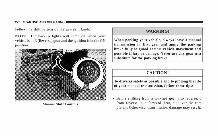
Follow the shift pattern on the gearshift knob.
NOTE: The backup lights will come on when yourvehicle is in R (Reverse) gear and the ignition is in the ONposition.
WARNING!
When parking your vehicle, always leave a manualtransmission in first gear and apply the parkingbrake fully to guard against vehicle movement andpossible injury or damage. Never use any gear as asubstitute for the parking brake.
CAUTION!
To drive as safely as possible and to prolong the lifeof your manual transmission, follow these tips:
• Before shifting from a forward gear into reverse, orfrom reverse to a forward gear, stop vehicle com-pletely. Otherwise, transmission damage may result.
Manual Shift Controls
270 STARTING AND OPERATING
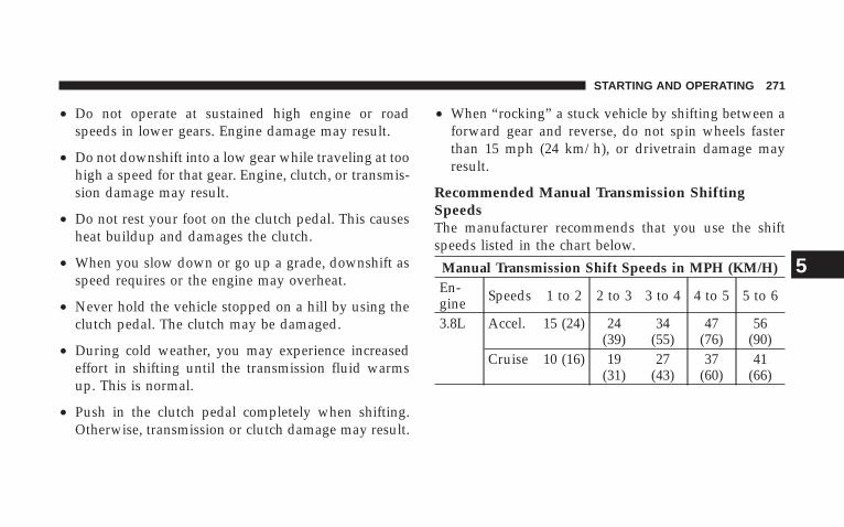
• Do not operate at sustained high engine or roadspeeds in lower gears. Engine damage may result.
• Do not downshift into a low gear while traveling at toohigh a speed for that gear. Engine, clutch, or transmis-sion damage may result.
• Do not rest your foot on the clutch pedal. This causesheat buildup and damages the clutch.
• When you slow down or go up a grade, downshift asspeed requires or the engine may overheat.
• Never hold the vehicle stopped on a hill by using theclutch pedal. The clutch may be damaged.
• During cold weather, you may experience increasedeffort in shifting until the transmission fluid warmsup. This is normal.
• Push in the clutch pedal completely when shifting.Otherwise, transmission or clutch damage may result.
• When “rocking” a stuck vehicle by shifting between aforward gear and reverse, do not spin wheels fasterthan 15 mph (24 km/h), or drivetrain damage mayresult.
Recommended Manual Transmission ShiftingSpeedsThe manufacturer recommends that you use the shiftspeeds listed in the chart below.
Manual Transmission Shift Speeds in MPH (KM/H)En-gine Speeds 1 to 2 2 to 3 3 to 4 4 to 5 5 to 6
3.8L Accel. 15 (24) 24(39)
34(55)
47(76)
56(90)
Cruise 10 (16) 19(31)
27(43)
37(60)
41(66)
STARTING AND OPERATING 271
5
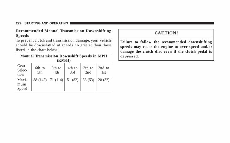
Recommended Manual Transmission DownshiftingSpeedsTo prevent clutch and transmission damage, your vehicleshould be downshifted at speeds no greater than thoselisted in the chart below:
Manual Transmission Downshift Speeds in MPH(KM/H)
GearSelec-tion
6th to5th
5th to4th
4th to3rd
3rd to2nd
2nd to1st
Maxi-mumSpeed
88 (142) 71 (114) 51 (82) 33 (53) 20 (32)
CAUTION!
Failure to follow the recommended downshiftingspeeds may cause the engine to over speed and/ordamage the clutch disc even if the clutch pedal isdepressed.
272 STARTING AND OPERATING
AUTOMATIC TRANSMISSION
CAUTION!
Damage to the transmission may occur if the follow-ing precautions are not observed:
• Shift into P (Park) only after the vehicle has cometo a complete stop.
• Shift into or out of R (Reverse) only after thevehicle has come to a complete stop and the engineis at idle speed.
• Do not shift from R (Reverse), P (Park), or N(Neutral) into any forward gear when the engine isabove idle speed.
• Before shifting into any gear, make sure your footis firmly on the brake pedal.
WARNING!
It is dangerous to shift the selector lever out of P(Park) or N (Neutral) if the engine speed is higherthan idle speed. If your foot is not firmly on thebrake pedal, the vehicle could accelerate quicklyforward or in reverse. You could lose control of thevehicle and hit someone or something. Only shiftinto gear when the engine is idling normally andwhen your foot is firmly on the brake pedal.
STARTING AND OPERATING 273
5
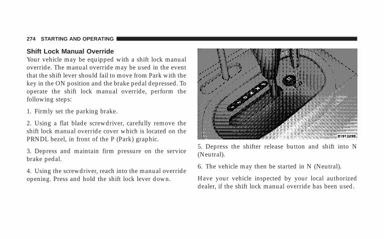
Shift Lock Manual OverrideYour vehicle may be equipped with a shift lock manualoverride. The manual override may be used in the eventthat the shift lever should fail to move from Park with thekey in the ON position and the brake pedal depressed. Tooperate the shift lock manual override, perform thefollowing steps:
1. Firmly set the parking brake.
2. Using a flat blade screwdriver, carefully remove theshift lock manual override cover which is located on thePRNDL bezel, in front of the P (Park) graphic.
3. Depress and maintain firm pressure on the servicebrake pedal.
4. Using the screwdriver, reach into the manual overrideopening. Press and hold the shift lock lever down.
5. Depress the shifter release button and shift into N(Neutral).
6. The vehicle may then be started in N (Neutral).
Have your vehicle inspected by your local authorizeddealer, if the shift lock manual override has been used.
274 STARTING AND OPERATING
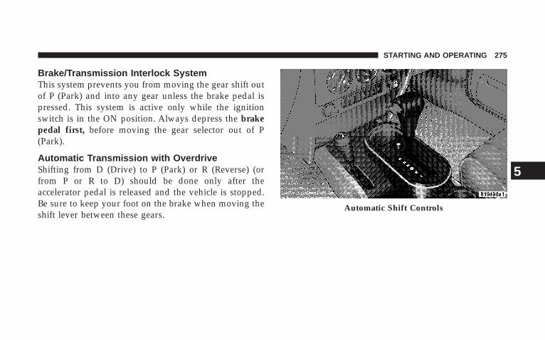
Brake/Transmission Interlock SystemThis system prevents you from moving the gear shift outof P (Park) and into any gear unless the brake pedal ispressed. This system is active only while the ignitionswitch is in the ON position. Always depress the brakepedal first, before moving the gear selector out of P(Park).
Automatic Transmission with OverdriveShifting from D (Drive) to P (Park) or R (Reverse) (orfrom P or R to D) should be done only after theaccelerator pedal is released and the vehicle is stopped.Be sure to keep your foot on the brake when moving theshift lever between these gears.
Automatic Shift Controls
STARTING AND OPERATING 275
5
Gear RangesDO NOT race the engine when shifting from P (Park) orN (Neutral) position into another gear range.
P (Park)This gear position supplements the parking brake bylocking the transmission. The engine can be started inthis range. Never use P (Park) while the vehicle is inmotion. Apply the parking brake when leaving thevehicle in this range. Always apply parking brake first,then place the selector in P (Park) position.
WARNING!
Never use P (Park) position as a substitute for theparking brake. Always apply parking brake fullywhen parked to guard against vehicle movement andpossible injury or damage.
WARNING!
It is dangerous to shift the selector lever out of P(Park) or N (Neutral) if the engine speed is higherthan idle speed. If your foot is not firmly on thebrake pedal, the vehicle could accelerate quicklyforward or in reverse. You could lose control of thevehicle and hit someone or something. Only shiftinto gear when the engine is idling normally andwhen your right foot is firmly on the brake pedal.
276 STARTING AND OPERATING
R (Reverse)Use this range only after the vehicle has come to acomplete stop.
N (Neutral)Shift into N (Neutral) when the vehicle is standing forprolonged periods with the engine running. The enginemay be started in this range. Set the parking brake if youmust leave the vehicle.
NOTE: Towing the vehicle, coasting, or driving for anyother reason with selector lever in N (Neutral) can resultin severe transmission damage. Refer to “RecreationalTowing” in Section 5 and “Towing a Disabled Vehicle” inSection 6 of this manual.
Overdrive (O/D)For most city and highway driving. The transmissioncontains an electronically controlled Overdrive, and willautomatically shift from D (Drive) to O/D (Overdrive) ifthe following conditions are present:
• The transmission selector is in D (Drive).
• The O/D OFF switch has not been activated.
• Vehicle speed is above approximately 30 mph (48km/h).
STARTING AND OPERATING 277
5
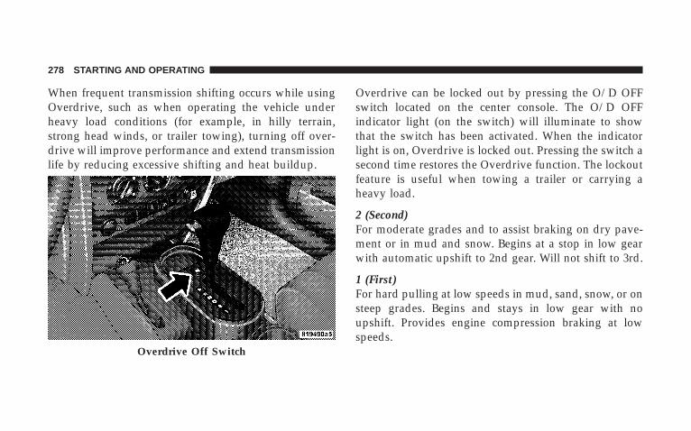
When frequent transmission shifting occurs while usingOverdrive, such as when operating the vehicle underheavy load conditions (for example, in hilly terrain,strong head winds, or trailer towing), turning off over-drive will improve performance and extend transmissionlife by reducing excessive shifting and heat buildup.
Overdrive can be locked out by pressing the O/D OFFswitch located on the center console. The O/D OFFindicator light (on the switch) will illuminate to showthat the switch has been activated. When the indicatorlight is on, Overdrive is locked out. Pressing the switch asecond time restores the Overdrive function. The lockoutfeature is useful when towing a trailer or carrying aheavy load.
2 (Second)For moderate grades and to assist braking on dry pave-ment or in mud and snow. Begins at a stop in low gearwith automatic upshift to 2nd gear. Will not shift to 3rd.
1 (First)For hard pulling at low speeds in mud, sand, snow, or onsteep grades. Begins and stays in low gear with noupshift. Provides engine compression braking at lowspeeds.
Overdrive Off Switch
278 STARTING AND OPERATING

WARNING!
Never use P (Park) position with an automatic trans-mission as a substitute for the parking brake. Alwaysapply parking brake fully when parked to guardagainst vehicle movement and possible injury ordamage.
CAUTION!
• Before moving the shift lever out of P (Park), youmust turn the ignition from LOCK so the steeringwheel and shift lever are released. Otherwise,damage to steering column or shifter could result.
• Never race the engine with the brakes on and thevehicle in gear, and never hold the vehicle on anincline without applying the brakes. These prac-tices can overheat and damage the transmission.
• When “rocking” a stuck vehicle by moving be-tween D (Drive) and R (Reverse), do not spin thewheels faster than 15 mph (24 km/h), or drivetraindamage may result.
STARTING AND OPERATING 279
5
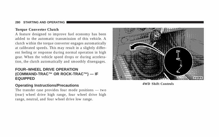
Torque Converter ClutchA feature designed to improve fuel economy has beenadded to the automatic transmission of this vehicle. Aclutch within the torque converter engages automaticallyat calibrated speeds. This may result in a slightly differ-ent feeling or response during normal operation in highgear. When the vehicle speed drops or during accelera-tion, the clutch automatically and smoothly disengages.
FOUR–WHEEL DRIVE OPERATION(COMMAND-TRAC™ OR ROCK-TRAC™) — IFEQUIPPED
Operating Instructions/PrecautionsThe transfer case provides four mode positions — two(rear) wheel drive high range, four wheel drive highrange, neutral, and four wheel drive low range.
4WD Shift Controls
280 STARTING AND OPERATING
This transfer case is intended to be driven in the twowheel drive (2H) position for normal street and highwayconditions such as hard surfaced roads.
In the events when additional traction is required, thetransfer case 4H and 4L positions can be used to lock thefront and rear driveshafts together and force the frontand rear wheels to rotate at the same speed. This isaccomplished by simply moving the shift lever to thesepositions. The 4H and 4L positions are intended for loose,slippery road surfaces only and not intended for normaldriving. Driving in the 4H and 4L positions on hardsurfaced roads will cause increased tire wear and damageto the driveline components.
The “4WD Indicator Light” (located in the instrumentcluster) alerts the driver that the vehicle is in four wheeldrive and that the front and rear driveshafts are lockedtogether. This light illuminates when the transfer case isshifted into the 4H position.
NOTE: Do not attempt to make a shift while only thefront or rear wheels are spinning. The transfer case is notequipped with a synchronizer and therefore the front andrear driveshafts speeds must be equal for the shift to takeplace. Shifting while only the front or rear wheels arespinning can cause damage to the transfer case.
When operating your vehicle in 4L, the engine speed isapproximately three times (four times for Rubicon mod-els) that of the 2H or 4H positions at a given road speed.Take care not to overspeed the engine.
Proper operation of four wheel drive vehicles depends ontires of equal size, type, and circumference on eachwheel. Any difference will adversely affect shifting andcause damage to the transfer case.
Because four wheel drive provides improved traction,there is a tendency to exceed safe turning and stoppingspeeds. Do not go faster than road conditions permit.
STARTING AND OPERATING 281
5
WARNING!
You or others could be injured if you leave thevehicle unattended with the transfer case in the N(Neutral) position without first fully engaging theparking brake. The transfer case N (Neutral) positiondisengages both the front and rear driveshafts fromthe powertrain and will allow the vehicle to moveregardless of the transmission position. The parkingbrake should always be applied when the driver isnot in the vehicle.
Shift Positions
For additional information on the appropriate use of eachtransfer case mode position, see the information below:
2H PositionRear Wheel Drive High Range — Normal street andhighway driving. Hard surfaced roads.
4H PositionFour Wheel Drive High Range — Locks the front and reardriveshafts together. Forces the front and rear wheels torotate at the same speed. This range (4H) providesadditional traction for loose, slippery road surfaces andshould not be used on wet or dry pavement.
WARNING!
Do not drive this vehicle in excess of 50 mph (80km/h) with the transfer case in the four wheel drivehigh range (4H). Failure to follow this warning canresult in loss of control and an accident causingserious and fatal injuries.
282 STARTING AND OPERATING

The “4WD Indicator Light” (located in the instrumentcluster) will illuminate when the transfer case is shiftedinto the 4H position.
N (Neutral) PositionNeutral — Disengages both the front and rear driveshaftsfrom the powertrain. To be used for flat towing behindanother vehicle. Refer to “Recreational Towing” in Sec-tion 5 of this manual.
4L PositionFour Wheel Drive Low Range — Locks the front and reardriveshafts together. Forces the front and rear wheels torotate at the same speed. Additional traction and maxi-mum pulling power for loose, slippery road surfacesonly. Do not exceed 25 mph (40 km/h).
The “4WD Indicator Light” (located in the instrumentcluster) will illuminate when the transfer case is shiftedinto the 4L position.
Shifting Procedure
2H to 4H or 4H to 2HShifting between 2H and 4H can be made with thevehicle stopped or in motion. If the vehicle is in motion,shifts can be made up to 50 mph (80 km/h). With thevehicle in motion, the transfer case will engage/disengage faster if you momentarily release the accelera-tor pedal after completing the shift. Apply a constantforce when shifting the transfer case lever.
4H to 4L or 4L to 4HWith the vehicle rolling at 2 to 3 mph (3 to 5 km/h), shiftan automatic transmission to N (Neutral) or depress theclutch pedal on a manual transmission. While the vehicleis coasting at 2 to 3 mph (3 to 5 km/h), shift the transfercase lever firmly to the desired position. Do not pause intransfer case N (Neutral).
STARTING AND OPERATING 283
5
NOTE: Pausing in transfer case N (Neutral) in vehiclesequipped with an automatic transmission may requireshutting the engine OFF to avoid gear clash whilecompleting the shift. If difficulty occurs, shift the auto-matic transmission to N (Neutral), hold foot on brake,and turn the engine OFF. Make shift to desired mode.
NOTE: Shifting into or out of 4L is possible with thevehicle completely stopped, however, difficulty may oc-cur due to the mating teeth not being properly aligned.Several attempts may be required for clutch teeth align-ment and shift completion to occur. The preferredmethod is with the vehicle rolling at 2 to 3 mph (3 to 5km/h). Avoid attempting to engage or disengage 4L withthe vehicle moving faster than 2 to 3 mph (3 to 5 km/h).
WARNING!
Failure to engage a position completely can causetransfer case damage or loss of power and vehiclecontrol. You could have an injury accident. Do notdrive the vehicle unless the transfer case is fullyengaged.
TRAC-LOK™ REAR AXLE — IF EQUIPPEDThe Trac-Lok™ rear axle provides a constant drivingforce to both rear wheels and reduces wheel spin causedby the loss of traction at one driving wheel. If tractiondiffers between the two rear wheels, the differentialautomatically proportions the usable torque by providingmore torque to the wheel that has traction.
284 STARTING AND OPERATING
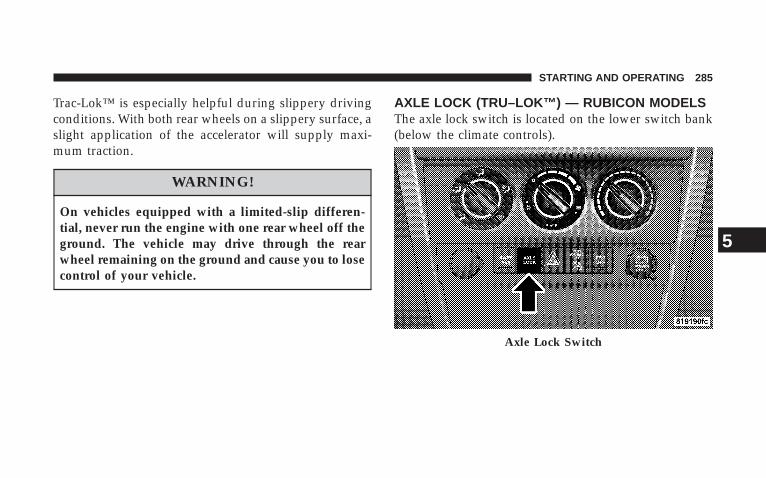
Trac-Lok™ is especially helpful during slippery drivingconditions. With both rear wheels on a slippery surface, aslight application of the accelerator will supply maxi-mum traction.
WARNING!
On vehicles equipped with a limited-slip differen-tial, never run the engine with one rear wheel off theground. The vehicle may drive through the rearwheel remaining on the ground and cause you to losecontrol of your vehicle.
AXLE LOCK (TRU–LOK™) — RUBICON MODELSThe axle lock switch is located on the lower switch bank(below the climate controls).
Axle Lock Switch
STARTING AND OPERATING 285
5
This feature will only activate when the following con-ditions are met:
• Key in ignition, vehicle in 4L (Low) range.
• Vehicle speed should be 10 mph (16 km/h) or less.
To activate the system, press the bottom of the switchonce to lock the rear axle only (the “Rear Axle LockIndicator Light” will illuminate), press the bottom of theswitch again to lock the front axle (the “Front Axle LockIndicator Light” will illuminate). Once the rear axle islocked, pressing the switch again will lock or unlock thefront axle.
NOTE: The indicator lights will flash until the axles arefully locked or unlocked.
To unlock the axles, push the top of the switch.
Axle lock will disengage if the vehicle is taken out of 4L(Low) range, or the ignition switch is turned to the OFFposition.
REAR AXLE LOCK — 4WD NON-RUBICONMODELS (IF EQUIPPED)The rear axle lock switch is located on the lower switchbank (below the climate controls).
This feature will only activate when the following con-ditions are met:
• Key in ignition, vehicle in 4L (Low) range.
• Vehicle speed should be 10 mph (16 km/h) or less.
To activate the system, press the switch down to lock therear axle (the “Rear Axle Lock Indicator Light” willilluminate), press the switch up to unlock the rear axle.
NOTE: The indicator lights will flash until the axle isfully locked or unlocked.
The rear axle lock will disengage if the vehicle is takenout of 4L (Low) range, or the ignition switch is turned tothe OFF position.
286 STARTING AND OPERATING
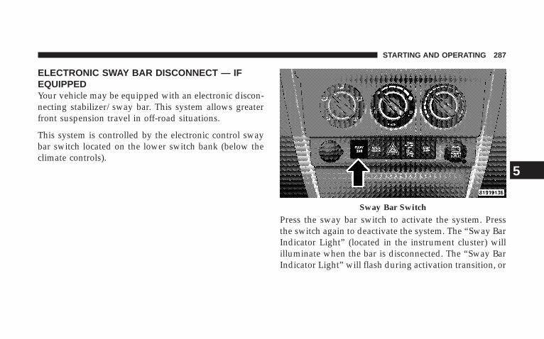
ELECTRONIC SWAY BAR DISCONNECT — IFEQUIPPEDYour vehicle may be equipped with an electronic discon-necting stabilizer/sway bar. This system allows greaterfront suspension travel in off-road situations.
This system is controlled by the electronic control swaybar switch located on the lower switch bank (below theclimate controls).
Press the sway bar switch to activate the system. Pressthe switch again to deactivate the system. The “Sway BarIndicator Light” (located in the instrument cluster) willilluminate when the bar is disconnected. The “Sway BarIndicator Light” will flash during activation transition, or
Sway Bar Switch
STARTING AND OPERATING 287
5
when activation conditions are not met. The stabilizer/sway bar should remain in on-road mode during normaldriving conditions.
WARNING!
Do not disconnect the stabilizer bar and drive onhard surfaced roads or at speeds above 18 mph (29km/h), you may lose control of the vehicle, whichcould result in serious injury. The front stabilizer barenhances vehicle stability and is necessary for main-taining control of the vehicle. The system monitorsvehicle speed and will attempt to reconnect thestabilizer bar at speeds over 18 mph (29 km/h). This isindicated by a flashing or solid “Sway Bar IndicatorLight.” Once vehicle speed is reduced below 14 mph(22 km/h), the system will once again attempt toreturn to off road mode.
To disconnect the stabilizer/sway bar, shift to either 4HIor 4LO (refer to “Four Wheel Drive Operation” in thissection) and press the stabilizer/sway bar button toobtain the off-road position. The amber indicator lightwill flash until the stabilizer/sway bar has been fullydisconnected.
NOTE: The stabilizer/sway bar may be torque lockeddue to left and right suspension height differences. Thiscondition is due to driving surface differences or vehicleloading. In order for the stabilizer/sway bar todisconnect/reconnect, the right and left halves of the barmust be aligned. This alignment may require that thevehicle be driven onto level ground or rocked from sideto side.
To return to on-road mode, press the stabilizer/sway barbutton again.
288 STARTING AND OPERATING
WARNING!
If the stabilizer/sway bar will not return to on-roadmode, vehicle stability is greatly reduced. Do notattempt to drive vehicle over 18 mph (29 km/h).Driving faster than 18 mph (29 km/h) may cause lossof control of the vehicle, which could result inserious injury. Contact your local authorized dealerfor assistance.
ON-ROAD DRIVING TIPSUtility vehicles have higher ground clearance and anarrower track to make them capable of performing in awide variety of off-road applications. Specific designcharacteristics give them a higher center of gravity thanordinary cars.
An advantage of the higher ground clearance is a betterview of the road, allowing you to anticipate problems.They are not designed for cornering at the same speeds asconventional 2-wheel drive vehicles any more than low-slung sports cars are designed to perform satisfactorily inoff-road conditions. If at all possible, avoid sharp turns orabrupt maneuvers. As with other vehicles of this type,failure to operate this vehicle correctly may result in lossof control or vehicle rollover.
STARTING AND OPERATING 289
5
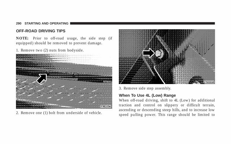
OFF-ROAD DRIVING TIPS
NOTE: Prior to off-road usage, the side step (ifequipped) should be removed to prevent damage.
1. Remove two (2) nuts from bodyside.
2. Remove one (1) bolt from underside of vehicle.
3. Remove side step assembly.
When To Use 4L (Low) RangeWhen off-road driving, shift to 4L (Low) for additionaltraction and control on slippery or difficult terrain,ascending or descending steep hills, and to increase lowspeed pulling power. This range should be limited to
290 STARTING AND OPERATING

extreme situations such as deep snow, mud, steep in-clines, or sand where additional low speed pulling poweris needed. Vehicle speeds in excess of 25 mph (40 km/h)should be avoided when in 4L (Low) range.
Driving Through WaterAlthough your vehicle is capable of driving throughwater, there are a number of precautions that must beconsidered before entering the water:
CAUTION!
When driving through water, do not exceed 5 mph (8km/h). Always check water depth before entering asa precaution, and check all fluids afterward. Drivingthrough water may cause damage that may not becovered by the new vehicle limited warranty.
Driving through water more than a few inches deep willrequire extra caution to ensure safety and prevent dam-age to your vehicle. If you must drive through water, tryto determine the depth and the bottom condition (andlocation of any obstacles) prior to entering. Proceed withcaution and maintain a steady controlled speed less than5 mph (8 km/h) in deep water to minimize wave effects.
Flowing WaterIf the water is swift flowing and rising (as in stormrun-off) avoid crossing until the water level recedesand/or the flow rate is reduced. If you must crossflowing water avoid depths in excess of 9 inches. Theflowing water can erode the streambed causing yourvehicle to sink into deeper water. Determine exit point(s)that are downstream of your entry point to allow fordrifting.
STARTING AND OPERATING 291
5
Standing WaterAvoid driving in standing water deeper than 20 inches,and reduce speed appropriately to minimize wave ef-fects. Maximum speed in 20 inches of water is less than 5mph (8 km/h).
MaintenanceAfter driving through deep water, inspect your vehiclefluids and lubricants (engine oil, transmission oil, axle,transfer case) to assure the fluids have not been contami-nated. Contaminated fluid (milky, foamy in appearance)should be flushed/changed as soon as possible to pre-vent component damage.
Driving In Snow, Mud and SandIn heavy snow, when pulling a load, or for additionalcontrol at slower speeds, shift the transmission to a lowgear and shift the transfer case to 4L (Low) if necessary.Refer to “Four-Wheel Drive Operation” in this section.
Do not shift to a lower gear than necessary to maintainheadway. Over-revving the engine can spin the wheelsand traction will be lost.
Avoid abrupt downshifts on icy or slippery roads, be-cause engine braking may cause skidding and loss ofcontrol.
Hill Climbing
NOTE: Before attempting to climb a hill, determine theconditions at the crest and/or on the other side.
Before climbing a steep hill, shift the transmission to alower gear and shift the transfer case to 4L (Low). Usefirst gear and 4L (Low) for very steep hills.
If you stall or begin to lose headway while climbing asteep hill, allow your vehicle to come to a stop andimmediately apply the brakes. Restart the engine andshift to R (Reverse). Back slowly down the hill allowingthe compression braking of the engine to help regulate
292 STARTING AND OPERATING
your speed. If the brakes are required to control vehiclespeed, apply them lightly and avoid locking or skiddingthe tires.
WARNING!
If the engine stalls or you lose headway or cannotmake it to the top of a steep hill or grade, neverattempt to turn around. To do so may result intipping and rolling the vehicle. Always back care-fully straight down a hill in R (Reverse) gear. Neverback down a hill in N (Neutral) using only the brake.
Remember, never drive diagonally across a hill-alwaysdrive straight up or down.
If the wheels start to slip as you approach the crest of ahill, ease off the accelerator and maintain headway by
turning the front wheels slowly left and right. This mayprovide a fresh “bite” into the surface and will usuallyprovide traction to complete the climb.
Traction DownhillShift the transmission into a low gear and the transfercase to 4L (Low) range. Let the vehicle go slowly downthe hill with all four wheels turning against enginecompression drag. This will permit you to control thevehicle speed and direction.
When descending mountains or hills, repeated brakingcan cause brake fade with loss of braking control. Avoidrepeated heavy braking by downshifting the transmis-sion whenever possible.
STARTING AND OPERATING 293
5
After Driving Off-RoadOff-road operation puts more stress on your vehicle thandoes most on-road driving. After going off-road it isalways a good idea to check for damage. That way youcan get any problems taken care of right away and haveyour vehicle ready when you need it.
• Completely inspect the underbody of your vehicle.Check tires, body structure, steering, suspension, andexhaust system for damage.
• Check threaded fasteners for looseness, particularly onthe chassis, drivetrain components, steering, and sus-pension. Retighten them, if required, and torque to thevalues specified in the Service Manual.
• Check for accumulations of plants or brush. Thesethings could be a fire hazard. They might hide damageto fuel lines, brake hoses, axle pinion seals, andpropeller shafts.
• After extended operation in mud, sand, water, orsimilar dirty conditions, have brake rotors, wheels,brake linings, and axle yokes inspected and cleaned assoon as possible.
WARNING!
Abrasive material in any part of the brakes may causeexcessive wear or unpredictable braking. You mightnot have full braking power when you need it toprevent an accident. If you have been operating yourvehicle in dirty conditions, get your brakes checkedand cleaned as necessary.
• If you experience unusual vibration after driving inmud, slush or similar conditions, check the wheels forimpacted material. Impacted material can cause awheel imbalance and freeing the wheels of it willcorrect the situation.
294 STARTING AND OPERATING
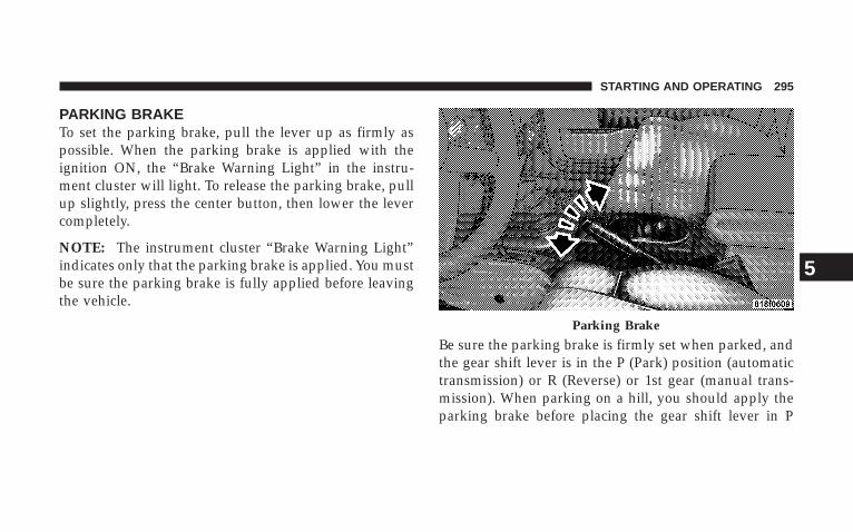
PARKING BRAKETo set the parking brake, pull the lever up as firmly aspossible. When the parking brake is applied with theignition ON, the “Brake Warning Light” in the instru-ment cluster will light. To release the parking brake, pullup slightly, press the center button, then lower the levercompletely.
NOTE: The instrument cluster “Brake Warning Light”indicates only that the parking brake is applied. You mustbe sure the parking brake is fully applied before leavingthe vehicle.
Be sure the parking brake is firmly set when parked, andthe gear shift lever is in the P (Park) position (automatictransmission) or R (Reverse) or 1st gear (manual trans-mission). When parking on a hill, you should apply theparking brake before placing the gear shift lever in P
Parking Brake
STARTING AND OPERATING 295
5
(Park), otherwise the load on the transmission lockingmechanism may make it difficult to move the selector outof P (Park).
WARNING!
• Always fully apply the parking brake when leav-ing your vehicle, or it may roll and cause damageor injury. Also, be certain to leave an automatictransmission in P (Park), a manual transmission inR (Reverse) or 1st gear. Failure to do so may allowthe vehicle to roll and cause damage or injury.
• Never leave children alone in a vehicle. Leavingchildren in a vehicle unattended is dangerous for anumber of reasons. A child or others could beseriously or fatally injured. Do not leave the keysin the ignition. A child could operate power win-dows, other controls, or move the vehicle.
When parking on a hill, turn the front wheels toward thecurb on a downhill grade and away from the curb on anuphill grade.
The parking brake should always be applied wheneverthe driver is not in the vehicle.
ANTI-LOCK BRAKE SYSTEMThe Anti-Lock Brake System is designed to aid the driverin maintaining vehicle control under adverse brakingconditions. The system operates with a separate com-puter to modulate hydraulic pressure to prevent wheellock-up and help avoid skidding on slippery surfaces.
All vehicle wheels and tires must be the same size andtype and tires must be properly inflated to produceaccurate signals for the computer.
296 STARTING AND OPERATING
WARNING!
Significant over or under-inflation of tires, or mixingsizes of tires or wheels on the vehicle can lead to lossof braking effectiveness.
The Anti-Lock Brake System conducts a low speed self-test at about 12 mph (20 km/h). If for any reason, yourfoot is on the brake when the vehicle reaches 12 mph (20km/h), this check will be delayed until 25 mph (40km/h).
The Anti-Lock Brake System pump motor runs duringthe self-test and during an ABS stop to provide theregulated hydraulic pressure. The motor pump makes alow humming noise during operation, this is normal.
During off-road use, loss of traction can temporarilydefeat the system and cause the warning light to illumi-nate. Turn the ignition OFF and ON again to restoreAnti-Lock Brake System function.
WARNING!
Pumping of the Anti-Lock Brakes will diminish theireffectiveness and may lead to an accident. Pumpingmakes the stopping distance longer. Just press firmlyon your brake pedal when you need to slow down orstop.
STARTING AND OPERATING 297
5
WARNING!
• Anti-lock system (ABS) cannot prevent the naturallaws of physics from acting on the vehicle, nor canit increase braking or steering efficiency beyondthat afforded by the condition of the vehiclebrakes and tires or the traction afforded.
• The ABS cannot prevent accidents, includingthose resulting from excessive speed in turns,following another vehicle too closely, or hydro-planing. Only a safe, attentive, and skillful drivercan prevent accidents.
• The capabilities of an ABS equipped vehicle mustnever be exploited in a reckless or dangerousmanner which could jeopardize the user’s safetyor the safety of others.
CAUTION!
The Anti-Lock Brake System is subject to possibledetrimental effects of electronic interference causedby improperly installed aftermarket radios ortelephones.
NOTE: During severe braking conditions, a pulsingsensation may occur and a clicking noise will be heard.This is normal, indicating that the Anti-Lock BrakeSystem is functioning.
POWER STEERINGThe standard power steering system will give you goodvehicle response and increased ease of maneuverabilityin tight spaces. The system will provide mechanicalsteering capability if power assist is lost.
298 STARTING AND OPERATING
If for some reason the power assist is interrupted, it willstill be possible to steer your vehicle. Under these condi-tions, you will observe a substantial increase in steeringeffort, especially at very low vehicle speeds and duringparking maneuvers.
NOTE: Increased noise levels at the end of the steeringwheel travel are considered normal and do not indicatethat there is a problem with the power steering system.
Upon initial start-up in cold weather, the power steeringpump may make noise for a short amount of time. This isdue to the cold, thick fluid in the steering system. Thisnoise should be considered normal, and it does not in anyway damage the steering system.
WARNING!
Continued operation with reduced power steeringassist could pose a safety risk to yourself and others.Service should be obtained as soon as possible.
CAUTION!
Prolonged operation of the steering system at the endof the steering wheel travel will increase the steeringfluid temperature and it should be avoided whenpossible. Damage to the power steering pump mayoccur.
STARTING AND OPERATING 299
5
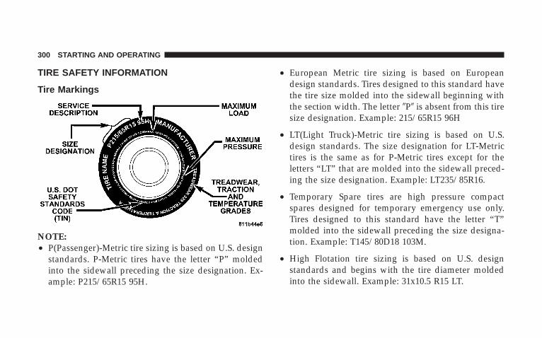
TIRE SAFETY INFORMATION
Tire Markings
NOTE:• P(Passenger)-Metric tire sizing is based on U.S. design
standards. P-Metric tires have the letter “P” moldedinto the sidewall preceding the size designation. Ex-ample: P215/65R15 95H.
• European Metric tire sizing is based on Europeandesign standards. Tires designed to this standard havethe tire size molded into the sidewall beginning withthe section width. The letter �P� is absent from this tiresize designation. Example: 215/65R15 96H
• LT(Light Truck)-Metric tire sizing is based on U.S.design standards. The size designation for LT-Metrictires is the same as for P-Metric tires except for theletters “LT” that are molded into the sidewall preced-ing the size designation. Example: LT235/85R16.
• Temporary Spare tires are high pressure compactspares designed for temporary emergency use only.Tires designed to this standard have the letter “T”molded into the sidewall preceding the size designa-tion. Example: T145/80D18 103M.
• High Flotation tire sizing is based on U.S. designstandards and begins with the tire diameter moldedinto the sidewall. Example: 31x10.5 R15 LT.
300 STARTING AND OPERATING
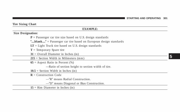
Tire Sizing Chart
EXAMPLE:Size Designation:
P = Passenger car tire size based on U.S. design standards�....blank....� = Passenger car tire based on European design standardsLT = Light Truck tire based on U.S. design standardsT = Temporary Spare tire31 = Overall Diameter in Inches (in)215 = Section Width in Milimeters (mm)65 = Aspect Ratio in Percent (%)
—Ratio of section height to section width of tire.10.5 = Section Width in Inches (in)R = Construction Code
—�R� means Radial Construction.—�D� means Diagonal or Bias Construction.
15 = Rim Diameter in Inches (in)
STARTING AND OPERATING 301
5
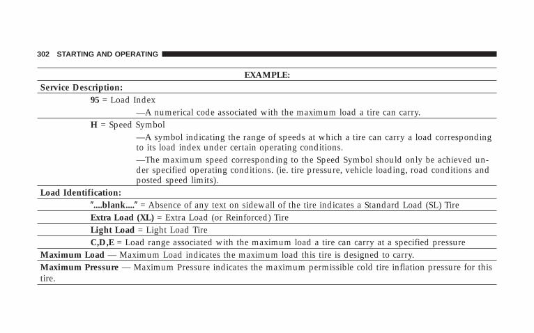
EXAMPLE:Service Description:
95 = Load Index—A numerical code associated with the maximum load a tire can carry.
H = Speed Symbol—A symbol indicating the range of speeds at which a tire can carry a load correspondingto its load index under certain operating conditions.—The maximum speed corresponding to the Speed Symbol should only be achieved un-der specified operating conditions. (ie. tire pressure, vehicle loading, road conditions andposted speed limits).
Load Identification:�....blank....� = Absence of any text on sidewall of the tire indicates a Standard Load (SL) TireExtra Load (XL) = Extra Load (or Reinforced) TireLight Load = Light Load TireC,D,E = Load range associated with the maximum load a tire can carry at a specified pressure
Maximum Load — Maximum Load indicates the maximum load this tire is designed to carry.Maximum Pressure — Maximum Pressure indicates the maximum permissible cold tire inflation pressure for thistire.
302 STARTING AND OPERATING
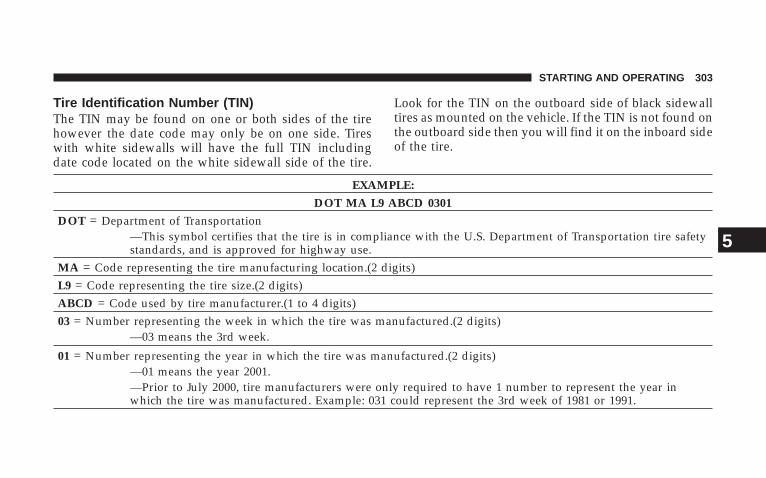
Tire Identification Number (TIN)The TIN may be found on one or both sides of the tirehowever the date code may only be on one side. Tireswith white sidewalls will have the full TIN includingdate code located on the white sidewall side of the tire.
Look for the TIN on the outboard side of black sidewalltires as mounted on the vehicle. If the TIN is not found onthe outboard side then you will find it on the inboard sideof the tire.
EXAMPLE:
DOT MA L9 ABCD 0301
DOT = Department of Transportation—This symbol certifies that the tire is in compliance with the U.S. Department of Transportation tire safetystandards, and is approved for highway use.
MA = Code representing the tire manufacturing location.(2 digits)L9 = Code representing the tire size.(2 digits)ABCD = Code used by tire manufacturer.(1 to 4 digits)03 = Number representing the week in which the tire was manufactured.(2 digits)
—03 means the 3rd week.
01 = Number representing the year in which the tire was manufactured.(2 digits)—01 means the year 2001.—Prior to July 2000, tire manufacturers were only required to have 1 number to represent the year inwhich the tire was manufactured. Example: 031 could represent the 3rd week of 1981 or 1991.
STARTING AND OPERATING 303
5
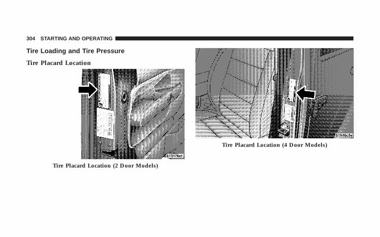
Tire Loading and Tire Pressure
Tire Placard Location
Tire Placard Location (2 Door Models)
Tire Placard Location (4 Door Models)
304 STARTING AND OPERATING
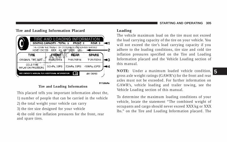
Tire and Loading Information Placard
This placard tells you important information about the,1) number of people that can be carried in the vehicle2) the total weight your vehicle can carry3) the tire size designed for your vehicle4) the cold tire inflation pressures for the front, rearand spare tires.
LoadingThe vehicle maximum load on the tire must not exceedthe load carrying capacity of the tire on your vehicle. Youwill not exceed the tire’s load carrying capacity if youadhere to the loading conditions, tire size and cold tireinflation pressures specified on the Tire and LoadingInformation placard and the Vehicle Loading section ofthis manual.
NOTE: Under a maximum loaded vehicle condition,gross axle weight ratings (GAWR’s) for the front and rearaxles must not be exceeded. For further information onGAWR’s, vehicle loading and trailer towing, see theVehicle Loading section of this manual.
To determine the maximum loading conditions of yourvehicle, locate the statement “The combined weight ofoccupants and cargo should never exceed XXX kg or XXXlbs.” on the Tire and Loading Information placard. The
Tire and Loading Information
STARTING AND OPERATING 305
5

combined weight of occupants, cargo/luggage andtrailer tongue weight (if applicable) should never exceedthe weight referenced here.
Steps for Determining Correct Load Limit
1. Locate the statement “The combined weight of occu-pants and cargo should never exceed XXX pounds” onyour vehicle’s placard.
2. Determine the combined weight of the driver andpassengers that will be riding in your vehicle.
3. Subtract the combined weight of the driver and pas-sengers from XXX kilograms or XXX pounds.
4. The resulting figure equals the available amount ofcargo and luggage load capacity. For example, if “XXX”amount equals 1400 lbs. and there will be five 150 lb.passengers in your vehicle, the amount of available cargoand luggage load capacity is 650 lb. (since 5 x 150 = 750,and 1400 – 750 = 650 lb.)
5. Determine the combined weight of luggage and cargobeing loaded on the vehicle. That weight may not safelyexceed the available cargo and luggage load capacitycalculated in step 4.
6. If your vehicle will be towing a trailer, load from yourtrailer will be transferred to your vehicle. Consult thismanual to determine how this reduces the availablecargo and luggage load capacity of your vehicle.
NOTE: The following table shows examples on how tocalculate total load, cargo/luggage and towing capacitiesof your vehicle with varying seating configurations andnumber and size of occupants. This table is for illustra-tion purposes only and may not be accurate for theseating and load carry capacity of your vehicle.
NOTE: For the following example the combined weightof occupants and cargo should never exceed 865 lbs. (392Kg).
306 STARTING AND OPERATING
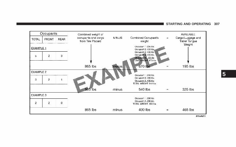
STARTING AND OPERATING 307
5
WARNING!
Overloading of your tires is dangerous. Overloadingcan cause tire failure, affect vehicle handling, andincrease your stopping distance. Use tires of therecommended load capacity for your vehicle. Neveroverload them.
TIRES — GENERAL INFORMATION
Tire PressureProper tire inflation pressure is essential to the safe andsatisfactory operation of your vehicle. Three primaryareas are affected by improper tire pressure:
1. Safety—
WARNING!
Improperly inflated tires are dangerous and can causeaccidents.
• Under inflation increases tire flexing and can result intire failure.
• Over inflation reduces a tire’s ability to cushionshock. Objects on the road and chuck holes can causedamage that results in tire failure.
• Unequal tire pressures can cause steering problems.You could lose control of your vehicle.
• Overinflated or under inflated tires can affect vehiclehandling and can fail suddenly, resulting in loss ofvehicle control.
• Unequal tire pressures from one side of the vehicle tothe other can cause the vehicle to drift to the right or left.
Always drive with each tire properly inflated.
308 STARTING AND OPERATING
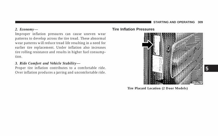
2. Economy—Improper inflation pressures can cause uneven wearpatterns to develop across the tire tread. These abnormalwear patterns will reduce tread life resulting in a need forearlier tire replacement. Under inflation also increasestire rolling resistance and results in higher fuel consump-tion.
3. Ride Comfort and Vehicle Stability—Proper tire inflation contributes to a comfortable ride.Over inflation produces a jarring and uncomfortable ride.
Tire Inflation Pressures
Tire Placard Location (2 Door Models)
STARTING AND OPERATING 309
5
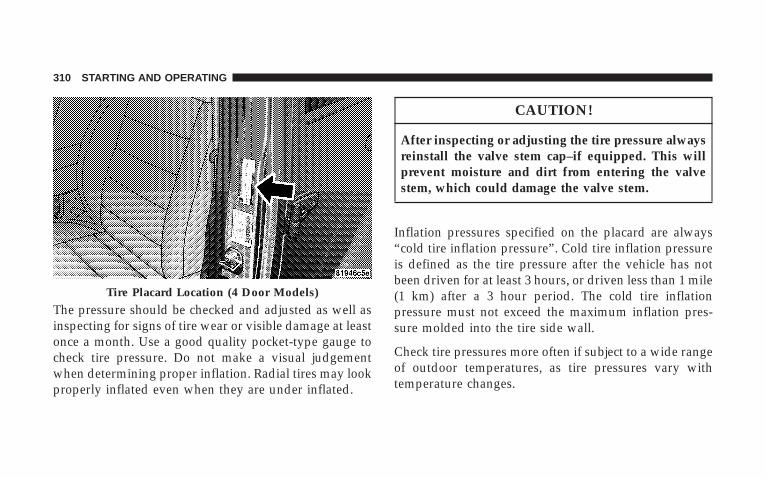
The pressure should be checked and adjusted as well asinspecting for signs of tire wear or visible damage at leastonce a month. Use a good quality pocket-type gauge tocheck tire pressure. Do not make a visual judgementwhen determining proper inflation. Radial tires may lookproperly inflated even when they are under inflated.
CAUTION!
After inspecting or adjusting the tire pressure alwaysreinstall the valve stem cap–if equipped. This willprevent moisture and dirt from entering the valvestem, which could damage the valve stem.
Inflation pressures specified on the placard are always“cold tire inflation pressure”. Cold tire inflation pressureis defined as the tire pressure after the vehicle has notbeen driven for at least 3 hours, or driven less than 1 mile(1 km) after a 3 hour period. The cold tire inflationpressure must not exceed the maximum inflation pres-sure molded into the tire side wall.
Check tire pressures more often if subject to a wide rangeof outdoor temperatures, as tire pressures vary withtemperature changes.
Tire Placard Location (4 Door Models)
310 STARTING AND OPERATING
Tire pressures change by approximately 1 psi (7 kPa) per12° F (7° C) of air temperature change. Keep this in mindwhen checking tire pressure inside a garage especially inthe winter.
Example: If garage temperature = 68° F (20° C) and theoutside temperature = 32° F (0° C) then the cold tireinflation pressure should be increased by 3 psi (21 kPa),which equals 1 psi (7 kPa) for every 12° F (7° C) for thisoutside temperature condition.
Tire pressure may increase from 2 to 6 psi (13 to 40 kPa)during operation. DO NOT reduce this normal pressurebuild up or your tire pressure will be too low.
Tire Pressures for High Speed OperationThe manufacturer advocates driving at safe speedswithin posted speed limits. Where speed limits or condi-tions are such that the vehicle can be driven at high
speeds, maintaining correct tire inflation pressure is veryimportant. Increased tire pressure and reduced vehicleloading may be required for high speed vehicle opera-tion. Refer to original equipment or an authorized tiredealer for recommended safe operating speeds, loadingand cold tire inflation pressures.
WARNING!
High speed driving with your vehicle under load isdangerous. The added strain on your tires couldcause them to fail. You could have a serious accident.Don’t drive a vehicle loaded to maximum capacity atcontinuous speeds above 75 mph (120 km/h).
STARTING AND OPERATING 311
5
Radial-Ply Tires
WARNING!
Combining radial ply tires with other types of tireson your vehicle will cause your vehicle to handlepoorly. The instability could cause an accident. Al-ways use radial tires in sets of four. Never combinethem with other types of tires.
Cuts and punctures in radial tires are repairable only inthe tread area because of sidewall flexing. Consult yourauthorized dealer for radial tire repairs.
Tire SpinningWhen stuck in mud, sand, snow, or ice conditions, do notspin your vehicle’s wheels above 35 mph (55 km/h).
WARNING!
Fast spinning tires can be dangerous. Forces gener-ated by excessive wheel speeds may cause tire dam-age or failure. A tire could explode and injure some-one. Do not spin your vehicle’s wheels faster than 35mph (55 km/h) when you are stuck, and do not letanyone near a spinning wheel no matter what thespeed.
Tread Wear IndicatorsTread wear indicators are in the original equipment tiresto help you in determining when your tires should bereplaced.
312 STARTING AND OPERATING
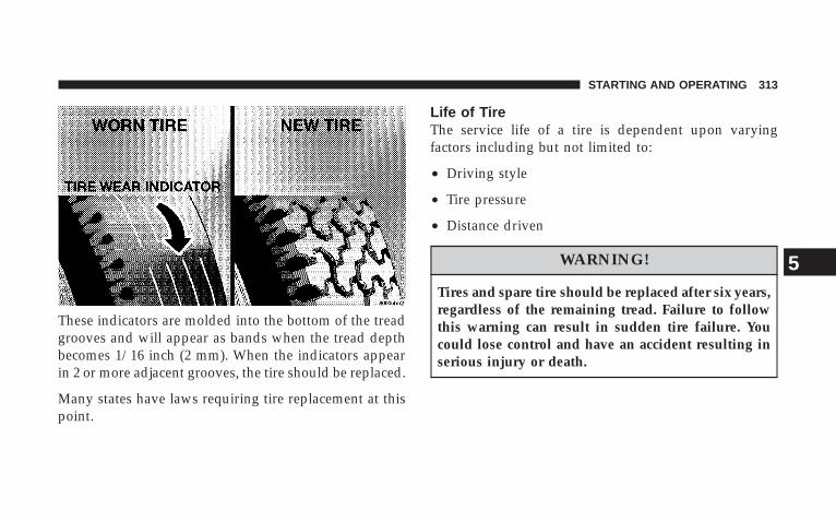
These indicators are molded into the bottom of the treadgrooves and will appear as bands when the tread depthbecomes 1/16 inch (2 mm). When the indicators appearin 2 or more adjacent grooves, the tire should be replaced.
Many states have laws requiring tire replacement at thispoint.
Life of TireThe service life of a tire is dependent upon varyingfactors including but not limited to:
• Driving style
• Tire pressure
• Distance driven
WARNING!
Tires and spare tire should be replaced after six years,regardless of the remaining tread. Failure to followthis warning can result in sudden tire failure. Youcould lose control and have an accident resulting inserious injury or death.
STARTING AND OPERATING 313
5
Keep unmounted tires in a cool, dry place with as littleexposure to light as possible. Protect tires from contactwith oil, grease and gasoline.
Replacement TiresThe tires on your new vehicle provide a balance of manycharacteristics. They should be inspected regularly forwear and correct cold tire inflation pressure. The manu-facturer strongly recommends that you use tires equiva-lent to the originals in size, quality and performancewhen replacement is needed (see the paragraph on treadwear indicators). Refer to the Tire and Loading Informa-tion placard for the size designation of your tire. Theservice description and load identification will be foundon the original equipment tire. Failure to use equivalentreplacement tires may adversely affect the safety, han-dling, and ride of your vehicle. We recommend that youcontact your original equipment or an authorized tiredealer with any questions you may have on tire specifi-cations or capability.
WARNING!
• Do not use a tire, wheel size or rating other than thatspecified for your vehicle. Some combinations ofunapproved tires and wheels may change suspensiondimensions and performance characteristics, result-ing in changes to steering, handling, and braking ofyour vehicle. This can cause unpredictable handlingand stress to steering and suspension components.You could lose control and have an accident resultingin serious injury or death. Use only the tire and wheelsizes with load ratings approved for your vehicle.
• Never use a tire with a smaller load index or capacity,other than what was originally equipped on yourvehicle. Using a tire with a smaller load index couldresult in tire overloading and failure. You could losecontrol and have an accident.
• Failure to equip your vehicle with tires having ad-equate speed capability can result in sudden tirefailure and loss of vehicle control.
314 STARTING AND OPERATING
CAUTION!
Replacing original tires with tires of a different sizemay result in false speedometer and odometerreadings.
Alignment and BalancePoor suspension alignment may result in:
• Fast tire wear.
• Uneven tire wear, such as feathering and one-sidedwear.
• Vehicle pull to right or left.
Tires may also cause the vehicle to pull left or right.Alignment will not correct this problem. See your autho-rized dealer for proper diagnosis.
Improper alignment will not cause vehicle vibration.Vibration may be a result of tire and wheel out-of-balance. Proper balancing will reduce vibration andavoid tire cupping and spotty wear.
TIRE CHAINSInstall chains on rear tires only. Tire chains may beinstalled on all models except the Sahara and Rubicon.Follow these recommendations to guard against damageand excessive tire and chain wear:
• Use chains on P225/75R16 tires only. P245/75R16,P255/75R17, P255/70R18, and LT255/75R17 tires donot provide adequate clearance.
• Use SAE class “S” tire chains or traction devices only.
• Chains must be the proper size for the vehicle, asrecommended by the chain manufacturer.
• Follow tire chain manufacturer’s instructions formounting chains.
STARTING AND OPERATING 315
5
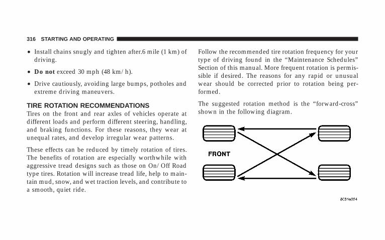
• Install chains snugly and tighten after.6 mile (1 km) ofdriving.
• Do not exceed 30 mph (48 km/h).
• Drive cautiously, avoiding large bumps, potholes andextreme driving maneuvers.
TIRE ROTATION RECOMMENDATIONSTires on the front and rear axles of vehicles operate atdifferent loads and perform different steering, handling,and braking functions. For these reasons, they wear atunequal rates, and develop irregular wear patterns.
These effects can be reduced by timely rotation of tires.The benefits of rotation are especially worthwhile withaggressive tread designs such as those on On/Off Roadtype tires. Rotation will increase tread life, help to main-tain mud, snow, and wet traction levels, and contribute toa smooth, quiet ride.
Follow the recommended tire rotation frequency for yourtype of driving found in the “Maintenance Schedules”Section of this manual. More frequent rotation is permis-sible if desired. The reasons for any rapid or unusualwear should be corrected prior to rotation being per-formed.
The suggested rotation method is the “forward-cross”shown in the following diagram.
316 STARTING AND OPERATING
TIRE PRESSURE MONITOR SYSTEM (TPMS) — IFEQUIPPEDThe Tire Pressure Monitoring System (TPMS) will warnthe driver of a low tire pressure based on the vehiclerecommended cold placard pressure.
The tire pressure will vary with temperature by about 1psi (6.9 kPa) for every 12°F (6.5°C). This means that whenthe outside temperature decreases, the tire pressure willdecrease. Tire pressure should always be set based oncold inflation tire pressure. This is defined as the tirepressure after a vehicle has not been driven for more than3 hours - and in outside ambient temperature. Refer tothe “Tires — General Information” in this section forinformation on how to properly inflate the vehicle’s tires.The tire pressure will also increase as the vehicle isdriven, this is normal and there should be no adjustmentfor this increased pressure.
The TPM System will warn the driver of a low tirepressure if the tire pressure falls below the low pressurewarning threshold for any reason, including low tem-perature effects.
The TPM System will continue to warn the driver of lowtire pressure as long as the condition exists, and will notturn off until the tire pressure is at or above recom-mended cold placard pressure. Once the low tire pressurewarning has been illuminated, the tire pressure must beincreased to the recommended cold placard pressure inorder for the “Tire Pressure Monitoring Telltale Light” tobe turned off. The system will automatically update andthe “Tire Pressure Monitoring Telltale Light” will extin-guish once the updated tire pressures have been received.The vehicle may need to be driven for up to 10 minutesabove 15 mph (25 km/h) to receive this information.
For example, your vehicle may have a recommendedcold (parked for more than 3 hours) air pressure of 35 psi
STARTING AND OPERATING 317
5
(241 kPa). If the ambient temperature is 65°F (18°C) andthe measured tire pressure is 30 psi (207 kPa), a tempera-ture drop to 20°F (-7°C) will decrease the tire pressure toapproximately 26 psi (179 kPa). This tire pressure issufficiently low enough to turn ON the “Tire PressureMonitoring Telltale Light.” Driving the vehicle may causethe tire pressure to rise to approximately 30 psi (207 kPa),but the “Tire Pressure Monitoring Telltale Light” will stillbe ON. In this situation, the “Tire Pressure MonitoringTelltale Light” will turn OFF only after the tires have beeninflated to the vehicle’s recommended cold placard pres-sure value.
Base System — If EquippedThe Tire Pressure Monitor System (TPMS) uses wirelesstechnology with wheel rim mounted electronic sensors tomonitor tire pressure levels. Sensors, mounted to eachwheel as part of the valve stem, transmit tire pressurereadings to the Receiver Module.
NOTE: It is particularly important, for you to check thetire pressure in all of your tires regularly and to maintainthe proper pressure.
The Tire Pressure Monitor System (TPMS) consists of thefollowing components:
• Receiver Module
• 4 Tire Pressure Monitoring Sensors
• Tire Pressure Monitoring Telltale Light
A tire pressure monitoring sensor is located in the sparewheel if the vehicle is equipped with a matching full sizespare wheel and tire assembly. The matching full sizespare tire can be used in place of any of the four roadtires.
318 STARTING AND OPERATING
The “Tire Pressure Monitoring Telltale Light” willilluminate in the instrument cluster, and an au-dible chime will be activated when one or more of
the four active road tire pressures are low. The audiblechime will sound once every ignition cycle for eachcondition that it detects. Should this occur, you shouldstop as soon as possible, check the inflation pressure ofeach tire on your vehicle, and inflate each tire to thepressure recommended by the vehicle manufacturer. Thesystem will automatically update and the “Tire PressureMonitoring Telltale Light” will extinguish once the up-dated tire pressures have been received. The vehicle mayneed to be driven for up to 10 minutes above 15 mph (25km/h) to receive this information. A low spare tire willnot cause the “Tire Pressure Monitoring Telltale Light” toilluminate or the chime to sound.
The “Tire Pressure Monitoring Telltale Light” will flashon and off for 60 seconds, and an audible chime willsound when a system fault is detected. The flash cyclewill repeat every ten minutes, without an audible chime,until the fault condition no longer exists. If the ignitionkey is cycled, this sequence will repeat, providing thesystem fault still exists.
NOTE: In the event that the matching full size spare tireis swapped with a low pressure road tire, the nextignition key cycle will still show the “Tire PressureMonitoring Telltale Light” to be ON, and a chime tosound. Driving the vehicle for up to 10 minutes above 15mph (25 kph) will turn OFF the “Tire Pressure Monitor-ing Telltale Light” as long as the spare tire or any otherroad tire(s) are not below the low pressure warningthreshold.
STARTING AND OPERATING 319
5
CAUTION!
The TPMS has been optimized for the originalequipment tires and wheels. TPMS pressures havebeen established for the tire size equipped on yourvehicle. Undesirable system operation or sensordamage may result when using replacement equip-ment that is not of the same size, type, and/or style.After-market wheels can cause sensor damage. Donot use tire sealant from a can, or balance beads ifyour vehicle is equipped with a TPMS, as damage tothe sensors may result.
CAUTION!
After inspecting or adjusting the tire pressure alwaysreinstall the valve stem cap. This will prevent mois-ture and dirt from entering the valve stem, whichcould damage the wheel rim sensor.
NOTE:• The TPMS is not intended to replace normal tire care
and maintenance, nor to provide warning of a tirefailure or condition.
• The TPMS should not be used as a tire pressure gaugewhile adjusting your tire pressure.
• Driving on a significantly under-inflated tire causesthe tire to overheat and can lead to tire failure.
320 STARTING AND OPERATING
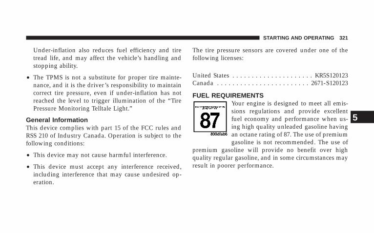
Under-inflation also reduces fuel efficiency and tiretread life, and may affect the vehicle’s handling andstopping ability.
• The TPMS is not a substitute for proper tire mainte-nance, and it is the driver’s responsibility to maintaincorrect tire pressure, even if under-inflation has notreached the level to trigger illumination of the “TirePressure Monitoring Telltale Light.”
General InformationThis device complies with part 15 of the FCC rules andRSS 210 of Industry Canada. Operation is subject to thefollowing conditions:
• This device may not cause harmful interference.
• This device must accept any interference received,including interference that may cause undesired op-eration.
The tire pressure sensors are covered under one of thefollowing licenses:
United States . . . . . . . . . . . . . . . . . . . . . KR5S120123Canada . . . . . . . . . . . . . . . . . . . . . . . . 2671-S120123
FUEL REQUIREMENTSYour engine is designed to meet all emis-sions regulations and provide excellentfuel economy and performance when us-ing high quality unleaded gasoline havingan octane rating of 87. The use of premiumgasoline is not recommended. The use of
premium gasoline will provide no benefit over highquality regular gasoline, and in some circumstances mayresult in poorer performance.
STARTING AND OPERATING 321
5
Light spark knock at low engine speeds is not harmful toyour engine. However, continued heavy spark knock athigh speeds can cause damage and immediate service isrequired.
Poor quality gasoline can cause problems such as hardstarting, stalling and hesitations. If you experience thesesymptoms, try another brand of gasoline before consid-ering service for the vehicle.
Over 40 auto manufacturer’s world wide have issued andendorsed consistent gasoline specifications (the World-wide Fuel Charter, WWFC) to define fuel propertiesnecessary to deliver enhanced emissions, performance,and durability for your vehicle. The manufacturer recom-mends the use of gasoline that meets the WWFC speci-fications if they are available.
Reformulated GasolineMany areas of the country require the use of cleanerburning gasoline referred to as “Reformulated Gasoline.”
Reformulated gasolines contains oxygenates, and arespecifically blended to reduce vehicle emissions andimprove air quality.
The manufacturer strongly supports the use of reformu-lated gasolines. Properly blended reformulated gasolineswill provide excellent performance and durability for theengine and fuel system components.
Gasoline/Oxygenate BlendsSome fuel suppliers blend unleaded gasoline with oxy-genates such as 10% ethanol, MTBE, and ETBE. Oxygen-ates are required in some areas of the country during thewinter months to reduce carbon monoxide emissions.Fuels blended with these oxygenates may be used inyour vehicle.
322 STARTING AND OPERATING

CAUTION!
DO NOT use gasolines containing Methanol or E85Ethanol. Use of these blends may result in startingand driveability problems and may damage criticalfuel system components.
Problems that result from using methanol/gasoline orE85 Ethanol blends are not the responsibility of themanufacturer. While MTBE is an oxygenate made fromMethanol, it does not have the negative effects of Metha-nol.
MMT In GasolineMMT is a manganese containing metallic additive that isblended into some gasoline to increase the octane num-ber. Gasolines blended with MMT offer no performanceadvantage beyond gasolines of the same octane numberwithout MMT. Gasolines blended with MMT have shown
to reduce spark plug life and reduce emission systemperformance in some vehicles. The manufacturer recom-mends using gasolines without MMT. Since the MMTcontent of gasoline may not be indicated on the pump,you should ask your gasoline retailer whether or nothis/her gasoline contains MMT.
It is even more important to look for gasolines withoutMMT in Canada, because MMT can be used at levelshigher than those allowed in the United States.
MMT is prohibited in Federal and California reformu-lated gasolines.
Materials Added To FuelAll gasoline sold in the United States is required tocontain effective detergent additives. Use of additionaldetergents or other additives are not needed undernormal conditions and would result in additional cost.Therefore you should not have to add anything to thefuel.
STARTING AND OPERATING 323
5
Fuel System Cautions
CAUTION!
Follow these guidelines to maintain your vehicle’sperformance:
• The use of leaded gasoline is prohibited by Federallaw. Using leaded gasoline can impair engine perfor-mance, damage the emission control system.
• An out-of-tune engine, or certain fuel or ignitionmalfunctions, can cause the catalytic converter tooverheat. If you notice a pungent burning odor orsome light smoke, your engine may be out of tune ormalfunctioning and may require immediate service.Contact your dealer for service assistance.
• The use of fuel additives which are now being sold asoctane enhancers is not recommended. Most of these
products contain high concentrations of methanol.Fuel system damage or vehicle performance problemsresulting from the use of such fuels or additives is notthe responsibility of the manufacturer.
NOTE: Intentional tampering with emissions controlsystems can result in civil penalties being assessedagainst you.
Carbon Monoxide Warnings
WARNING!
Carbon monoxide (CO) in exhaust gases is deadly.Follow the precautions below to prevent carbonmonoxide poisoning:
• Do not inhale exhaust gases. They contain carbonmonoxide, a colorless and odorless gas which can kill.Never run the engine in a closed area, such as a
324 STARTING AND OPERATING
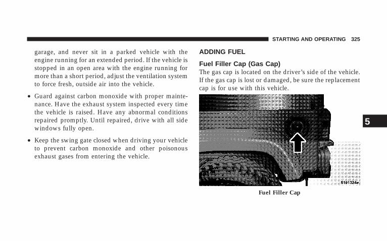
garage, and never sit in a parked vehicle with theengine running for an extended period. If the vehicle isstopped in an open area with the engine running formore than a short period, adjust the ventilation systemto force fresh, outside air into the vehicle.
• Guard against carbon monoxide with proper mainte-nance. Have the exhaust system inspected every timethe vehicle is raised. Have any abnormal conditionsrepaired promptly. Until repaired, drive with all sidewindows fully open.
• Keep the swing gate closed when driving your vehicleto prevent carbon monoxide and other poisonousexhaust gases from entering the vehicle.
ADDING FUEL
Fuel Filler Cap (Gas Cap)The gas cap is located on the driver’s side of the vehicle.If the gas cap is lost or damaged, be sure the replacementcap is for use with this vehicle.
Fuel Filler Cap
STARTING AND OPERATING 325
5
CAUTION!
Damage to the fuel system or emission control sys-tem could result from using an improper fuel cap(gas cap). A poorly fitting cap could let impuritiesinto the fuel system. Also, a poorly fitting after-market cap can cause the MIL (Malfunction IndicatorLight) to illuminate, due to fuel vapors escaping fromthe system.
CAUTION!
A poorly fitting gas cap may cause the MalfunctionIndicator Light to turn on.
CAUTION!
To avoid fuel spillage and overfilling, do not “topoff” the fuel tank after filling.
NOTE: When the fuel nozzle “clicks” or shuts off, thefuel tank is full.
WARNING!
• Never have any smoking materials lit in or nearthe vehicle when the gas cap is removed or thetank filled.
• Never add fuel when the engine is running. This isin violation of most state and federal fire regula-tions and will cause the malfunction indicatorlight to turn on.
326 STARTING AND OPERATING
NOTE: Tighten the gas cap about 1/4 turn until youhear one click. This is an indication that cap is properlytightened.
If the gas cap is not tighten properly, the MalfunctionIndicator Light will come on. Be sure the gas cap istightened every time the vehicle is refueled.
WARNING!
A fire may result if gasoline is pumped into aportable container that is inside of a vehicle. Youcould be burned. Always place gas containers on theground while filling.
CAUTION!
Damage to the fuel system or emission control sys-tem could result from using an improper fuel tankfiller cap (gas cap). A poorly fitting cap could letimpurities into the fuel system.
WARNING!
• Never add fuel when the engine is running.
• Never have any smoking materials lit in or nearthe vehicle when the fuel cap is removed or thetank filled.
STARTING AND OPERATING 327
5
VEHICLE LOADING
Certification LabelAs required by National Highway Traffic Safety Admin-istration Regulations, your vehicle has a certificationlabel affixed to the driver’s side door or pillar.
This label contains the month and year of manufacture,Gross Vehicle Weight Rating (GVWR), Gross Axle WeightRating (GAWR) front and rear, and Vehicle IdentificationNumber (VIN). A Month-Day-Hour (MDH) number isincluded on this label and indicates the Month, Day andHour of manufacture. The bar code that appears on thebottom of the label is your Vehicle Identification Number(VIN).
Gross Vehicle Weight Rating (GVWR)The GVWR is the total permissible weight of your vehicleincluding driver, passengers, vehicle, options, trailer
tongue weight, and cargo. The label also specifies maxi-mum capacities of front and rear axle systems (GAWR).Total load must be limited so GVWR and front and rearGAWR are not exceeded.
PayloadThe payload of a vehicle is defined as the allowable loadweight a truck can carry, including the weight of thedriver, all passengers, options and cargo.
Gross Axle Weight Rating (GAWR)The GAWR is the maximum permissible load on the frontand rear axles. The load must be distributed in the cargoarea so that the GAWR of each axle is not exceeded.
Each axle GAWR is determined by the components in thesystem with the lowest load carrying capacity (axle,springs, tires or wheels). Heavier axles or suspensioncomponents sometimes specified by purchasers for in-creased durability does not necessarily increase the vehi-cle’s GVWR.
328 STARTING AND OPERATING
Tire SizeThe tire size on the Label represents the actual tire size onyour vehicle. Replacement tires must be equal to the loadcapacity of this tire size.
Rim SizeThis is the rim size that is appropriate for the tire sizelisted.
Inflation PressureThis is the cold tire inflation pressure for your vehicle forall loading conditions up to full GAWR.
Curb WeightThe curb weight of a vehicle is defined as the total weightof the vehicle with all fluids, including vehicle fuel, at fullcapacity conditions, and with no occupants or cargoloaded into the vehicle. The front and rear curb weightvalues are determined by weighing your vehicle on acommercial scale before any occupants or cargo areadded.
LoadingThe actual total weight and the weight of the front andrear of your vehicle at the ground can best be determinedby weighing it when it is loaded and ready for operation.
The entire vehicle should first be weighed on a commer-cial scale to insure that the GVWR has not been exceeded.The weight on the front and rear of the vehicle shouldthen be determined separately to be sure that the load isproperly distributed over front and rear axle. Weighingthe vehicle may show that the GAWR of either the frontor rear axles has been exceeded but the total load iswithin the specified GVWR. If so, weight must be shiftedfrom front to rear or rear to front as appropriate until thespecified weight limitations are met. Store the heavieritems down low and be sure that the weight is distributedequally. Stow all loose items securely before driving.
STARTING AND OPERATING 329
5
Improper weight distributions can have an adverse effecton the way your vehicle steers and handles and the waythe brakes operate.
CAUTION!
Do not load your vehicle any heavier than the GVWRor the maximum front and rear GAWR. If you do,parts on your vehicle can break, or it can change theway your vehicle handles. This could cause you tolose control. Also overloading can shorten the life ofyour vehicle.
TRAILER TOWINGIn this section you will find safety tips and informationon limits to the type of towing you can reasonably dowith your vehicle. Before towing a trailer carefully re-view this information to tow your load as efficiently andsafely as possible.
To maintain warranty coverage, follow the requirementsand recommendations in this manual concerning ve-hicles used for trailer towing.
Common Towing DefinitionsThe following trailer towing related definitions will assistyou in understanding the following information:
Gross Vehicle Weight Rating (GVWR)The GVWR is the total allowable weight of your vehicle.This includes driver, passengers, cargo and tongueweight. The total load must be limited so that you do notexceed the GVWR.
330 STARTING AND OPERATING
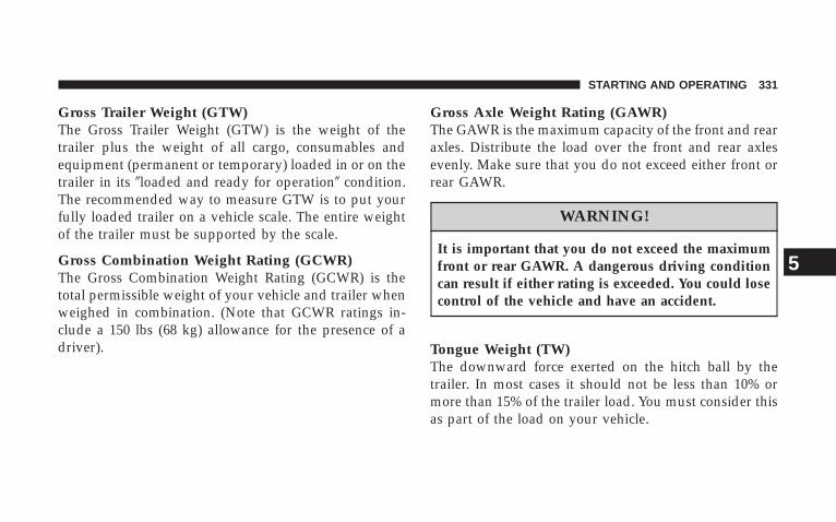
Gross Trailer Weight (GTW)The Gross Trailer Weight (GTW) is the weight of thetrailer plus the weight of all cargo, consumables andequipment (permanent or temporary) loaded in or on thetrailer in its �loaded and ready for operation� condition.The recommended way to measure GTW is to put yourfully loaded trailer on a vehicle scale. The entire weightof the trailer must be supported by the scale.
Gross Combination Weight Rating (GCWR)The Gross Combination Weight Rating (GCWR) is thetotal permissible weight of your vehicle and trailer whenweighed in combination. (Note that GCWR ratings in-clude a 150 lbs (68 kg) allowance for the presence of adriver).
Gross Axle Weight Rating (GAWR)The GAWR is the maximum capacity of the front and rearaxles. Distribute the load over the front and rear axlesevenly. Make sure that you do not exceed either front orrear GAWR.
WARNING!
It is important that you do not exceed the maximumfront or rear GAWR. A dangerous driving conditioncan result if either rating is exceeded. You could losecontrol of the vehicle and have an accident.
Tongue Weight (TW)The downward force exerted on the hitch ball by thetrailer. In most cases it should not be less than 10% ormore than 15% of the trailer load. You must consider thisas part of the load on your vehicle.
STARTING AND OPERATING 331
5
Frontal AreaThe maximum height and maximum width of the front ofa trailer.
Trailer Sway ControlThe trailer sway control is a telescoping link that can beinstalled between the hitch receiver and the trailer tonguethat typically provides adjustable friction associated withthe telescoping motion to dampen any unwanted trailerswaying motions while traveling.
Weight-Carrying HitchA weight-carrying hitch supports the trailer tongueweight, just as if it were luggage located at a hitch ball orsome other connecting point of the vehicle. These kind ofhitches are the most popular on the market today andthey’re commonly used to tow small- and medium-sizedtrailers.
Weight-Distributing HitchA weight-distributing system works by applying lever-age through spring (load) bars. They are typically usedfor heavier loads, to distribute trailer tongue weight tothe tow vehicle’s front axle and the trailer axle(s). Whenused in accordance with the manufacturers’ directions, itprovides for a more level ride, offering more consistentsteering and brake control thereby enhancing towingsafety. The addition of a friction/hydraulic sway controlalso dampens sway caused by traffic and crosswinds andcontributes positively to tow vehicle and trailer stability.Trailer sway control and a weight distributing (loadequalizing) hitch are recommended for heavier TongueWeights (TW) and may be required depending on Vehicleand Trailer configuration/loading to comply with GrossAxle Weight Rating (GAWR) requirements.
332 STARTING AND OPERATING
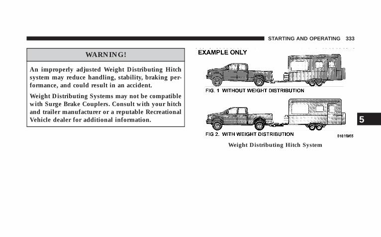
WARNING!
An improperly adjusted Weight Distributing Hitchsystem may reduce handling, stability, braking per-formance, and could result in an accident.
Weight Distributing Systems may not be compatiblewith Surge Brake Couplers. Consult with your hitchand trailer manufacturer or a reputable RecreationalVehicle dealer for additional information.
Weight Distributing Hitch System
STARTING AND OPERATING 333
5
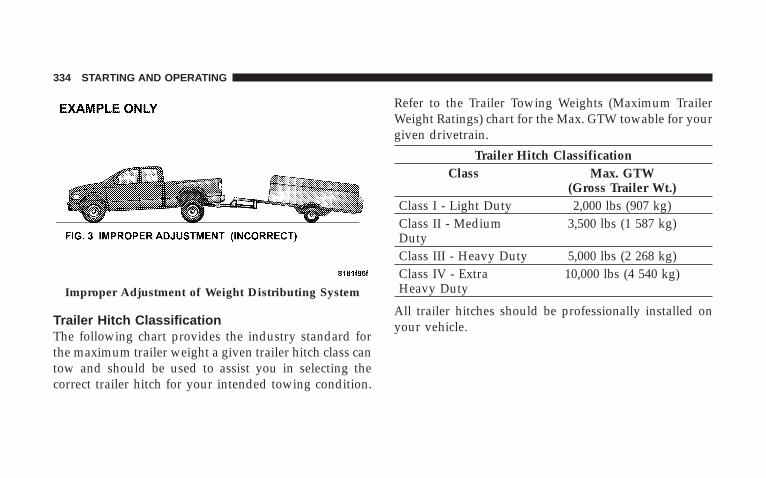
Trailer Hitch ClassificationThe following chart provides the industry standard forthe maximum trailer weight a given trailer hitch class cantow and should be used to assist you in selecting thecorrect trailer hitch for your intended towing condition.
Refer to the Trailer Towing Weights (Maximum TrailerWeight Ratings) chart for the Max. GTW towable for yourgiven drivetrain.
Trailer Hitch ClassificationClass Max. GTW
(Gross Trailer Wt.)Class I - Light Duty 2,000 lbs (907 kg)Class II - MediumDuty
3,500 lbs (1 587 kg)
Class III - Heavy Duty 5,000 lbs (2 268 kg)Class IV - ExtraHeavy Duty
10,000 lbs (4 540 kg)
All trailer hitches should be professionally installed onyour vehicle.
Improper Adjustment of Weight Distributing System
334 STARTING AND OPERATING
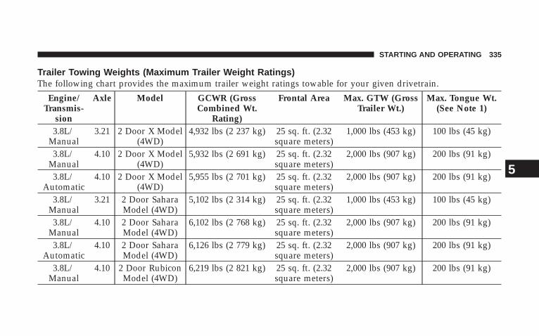
Trailer Towing Weights (Maximum Trailer Weight Ratings)The following chart provides the maximum trailer weight ratings towable for your given drivetrain.
Engine/Transmis-
sion
Axle Model GCWR (GrossCombined Wt.
Rating)
Frontal Area Max. GTW (GrossTrailer Wt.)
Max. Tongue Wt.(See Note 1)
3.8L/Manual
3.21 2 Door X Model(4WD)
4,932 lbs (2 237 kg) 25 sq. ft. (2.32square meters)
1,000 lbs (453 kg) 100 lbs (45 kg)
3.8L/Manual
4.10 2 Door X Model(4WD)
5,932 lbs (2 691 kg) 25 sq. ft. (2.32square meters)
2,000 lbs (907 kg) 200 lbs (91 kg)
3.8L/Automatic
4.10 2 Door X Model(4WD)
5,955 lbs (2 701 kg) 25 sq. ft. (2.32square meters)
2,000 lbs (907 kg) 200 lbs (91 kg)
3.8L/Manual
3.21 2 Door SaharaModel (4WD)
5,102 lbs (2 314 kg) 25 sq. ft. (2.32square meters)
1,000 lbs (453 kg) 100 lbs (45 kg)
3.8L/Manual
4.10 2 Door SaharaModel (4WD)
6,102 lbs (2 768 kg) 25 sq. ft. (2.32square meters)
2,000 lbs (907 kg) 200 lbs (91 kg)
3.8L/Automatic
4.10 2 Door SaharaModel (4WD)
6,126 lbs (2 779 kg) 25 sq. ft. (2.32square meters)
2,000 lbs (907 kg) 200 lbs (91 kg)
3.8L/Manual
4.10 2 Door RubiconModel (4WD)
6,219 lbs (2 821 kg) 25 sq. ft. (2.32square meters)
2,000 lbs (907 kg) 200 lbs (91 kg)
STARTING AND OPERATING 335
5
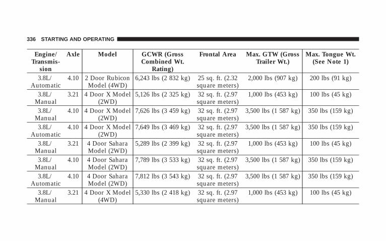
Engine/Transmis-
sion
Axle Model GCWR (GrossCombined Wt.
Rating)
Frontal Area Max. GTW (GrossTrailer Wt.)
Max. Tongue Wt.(See Note 1)
3.8L/Automatic
4.10 2 Door RubiconModel (4WD)
6,243 lbs (2 832 kg) 25 sq. ft. (2.32square meters)
2,000 lbs (907 kg) 200 lbs (91 kg)
3.8L/Manual
3.21 4 Door X Model(2WD)
5,126 lbs (2 325 kg) 32 sq. ft. (2.97square meters)
1,000 lbs (453 kg) 100 lbs (45 kg)
3.8L/Manual
4.10 4 Door X Model(2WD)
7,626 lbs (3 459 kg) 32 sq. ft. (2.97square meters)
3,500 lbs (1 587 kg) 350 lbs (159 kg)
3.8L/Automatic
4.10 4 Door X Model(2WD)
7,649 lbs (3 469 kg) 32 sq. ft. (2.97square meters)
3,500 lbs (1 587 kg) 350 lbs (159 kg)
3.8L/Manual
3.21 4 Door SaharaModel (2WD)
5,289 lbs (2 399 kg) 32 sq. ft. (2.97square meters)
1,000 lbs (453 kg) 100 lbs (45 kg)
3.8L/Manual
4.10 4 Door SaharaModel (2WD)
7,789 lbs (3 533 kg) 32 sq. ft. (2.97square meters)
3,500 lbs (1 587 kg) 350 lbs (159 kg)
3.8L/Automatic
4.10 4 Door SaharaModel (2WD)
7,812 lbs (3 543 kg) 32 sq. ft. (2.97square meters)
3,500 lbs (1 587 kg) 350 lbs (159 kg)
3.8L/Manual
3.21 4 Door X Model(4WD)
5,330 lbs (2 418 kg) 32 sq. ft. (2.97square meters)
1,000 lbs (453 kg) 100 lbs (45 kg)
336 STARTING AND OPERATING
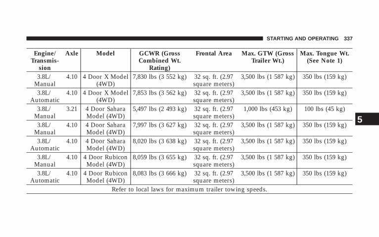
Engine/Transmis-
sion
Axle Model GCWR (GrossCombined Wt.
Rating)
Frontal Area Max. GTW (GrossTrailer Wt.)
Max. Tongue Wt.(See Note 1)
3.8L/Manual
4.10 4 Door X Model(4WD)
7,830 lbs (3 552 kg) 32 sq. ft. (2.97square meters)
3,500 lbs (1 587 kg) 350 lbs (159 kg)
3.8L/Automatic
4.10 4 Door X Model(4WD)
7,853 lbs (3 562 kg) 32 sq. ft. (2.97square meters)
3,500 lbs (1 587 kg) 350 lbs (159 kg)
3.8L/Manual
3.21 4 Door SaharaModel (4WD)
5,497 lbs (2 493 kg) 32 sq. ft. (2.97square meters)
1,000 lbs (453 kg) 100 lbs (45 kg)
3.8L/Manual
4.10 4 Door SaharaModel (4WD)
7,997 lbs (3 627 kg) 32 sq. ft. (2.97square meters)
3,500 lbs (1 587 kg) 350 lbs (159 kg)
3.8L/Automatic
4.10 4 Door SaharaModel (4WD)
8,020 lbs (3 638 kg) 32 sq. ft. (2.97square meters)
3,500 lbs (1 587 kg) 350 lbs (159 kg)
3.8L/Manual
4.10 4 Door RubiconModel (4WD)
8,059 lbs (3 655 kg) 32 sq. ft. (2.97square meters)
3,500 lbs (1 587 kg) 350 lbs (159 kg)
3.8L/Automatic
4.10 4 Door RubiconModel (4WD)
8,083 lbs (3 666 kg) 32 sq. ft. (2.97square meters)
3,500 lbs (1 587 kg) 350 lbs (159 kg)
Refer to local laws for maximum trailer towing speeds.
STARTING AND OPERATING 337
5
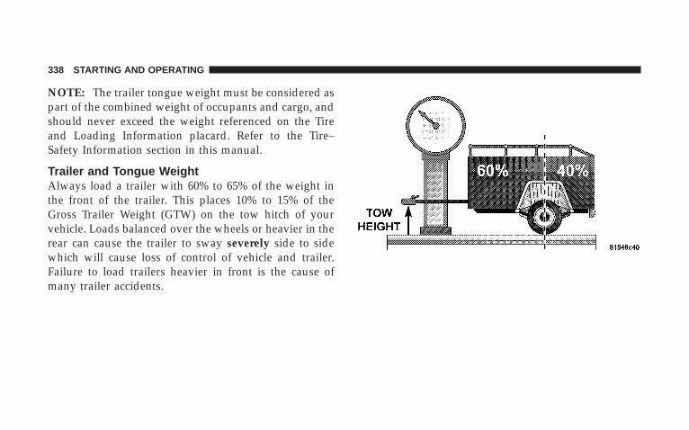
NOTE: The trailer tongue weight must be considered aspart of the combined weight of occupants and cargo, andshould never exceed the weight referenced on the Tireand Loading Information placard. Refer to the Tire–Safety Information section in this manual.
Trailer and Tongue WeightAlways load a trailer with 60% to 65% of the weight inthe front of the trailer. This places 10% to 15% of theGross Trailer Weight (GTW) on the tow hitch of yourvehicle. Loads balanced over the wheels or heavier in therear can cause the trailer to sway severely side to sidewhich will cause loss of control of vehicle and trailer.Failure to load trailers heavier in front is the cause ofmany trailer accidents.
338 STARTING AND OPERATING
Consider the following items when computing theweight on the rear axle of the vehicle:
• The tongue weight of the trailer.
• The weight of any other type of cargo or equipmentput in or on your vehicle.
• The weight of the driver and all passengers.
NOTE: Remember that everything put into or on thetrailer adds to the load on your vehicle. Also, additionalfactory-installed options, or dealer-installed options,must be considered as part of the total load on yourvehicle. Refer to the Tire and Loading Information plac-ard in the Tire Safety Information section of this manualfor the maximum combined weight of occupants andcargo for your vehicle.
Towing RequirementsTo promote proper break-in of your new vehicle driv-etrain components the following guidelines are recom-mended:
NOTE: Trailer towing requires special rear axle lubri-cant. Refer to “Fluids, Lubricants, and Genuine Parts” inSection 7 for more information.
CAUTION!
• Avoid towing a trailer for the first 500 miles (805km) of vehicle operation. Doing so may damageyour vehicle.
Perform the maintenance listed in Section 8 of thismanual. When towing a trailer, never exceed the GAWR,or GCWR, ratings.
STARTING AND OPERATING 339
5
WARNING!
Improper towing can lead to an injury accident.Follow these guidelines to make your trailer towingas safe as possible:
Make certain that the load is secured in the trailerand will not shift during travel. When traileringcargo that is not fully secured, dynamic load shiftscan occur that may be difficult for the driver tocontrol. You could lose control of your vehicle andhave an accident.
• When hauling cargo or towing a trailer, do not over-load your vehicle or trailer. Overloading can cause aloss of control, poor performance or damage to brakes,axle, engine, transmission, steering, suspension, chas-sis structure or tires.
• Safety chains must always be used between yourvehicle and trailer. Always connect the chains to theframe or hook retainers of the vehicle hitch. Cross thechains under the trailer tongue and allow enoughslack for turning corners.
• Vehicles with trailers should not be parked on a grade.When parking, apply the parking brake on the towvehicle. Put the tow vehicle automatic transmission inP (Park). With a manual transmission, shift the trans-mission into 1st gear. And with four-wheel-drive ve-hicles, make sure the transfer case is not in N (Neu-tral). Always, block or �chock� the trailer wheels.
• GCWR must not be exceeded.
• Total weight must be distributed between the towvehicle and the trailer such that the following fourratings are not exceeded:
1. GVWR
340 STARTING AND OPERATING
2. GTW
3. GAWR
4. Tongue weight rating for the trailer hitch utilized(This requirement may limit the ability to alwaysachieve the 10% to 15% range of tongue weight as apercentage of total trailer weight).
Towing Requirements — Tires
− Do not attempt to tow a trailer while using a compactspare tire.
− Proper tire inflation pressures are essential to the safeand satisfactory operation of your vehicle. Refer to theTires–General Information section of this manual onTire Pressures for proper tire inflation procedures.
− Also, check the trailer tires for proper tire inflationpressures before trailer usage.
− Check for signs of tire wear or visible tire damagebefore towing a trailer. Refer to the Tires–GeneralInformation section of this manual on Tread WearIndicators for the proper inspection procedure.
− When replacing tires, refer to the Tires–General Infor-mation section of this manual on Replacement Tires forproper tire replacement procedures. Replacing tireswith a higher load carrying capacity will not increasethe vehicle’s GVWR and GAWR limits.
Towing Requirements — Trailer Brakes
− Do not interconnect the hydraulic brake system orvacuum system of your vehicle with that of the trailer.This could cause inadequate braking and possiblepersonal injury.
− An electronically actuated trailer brake controller isrequired when towing a trailer with electronically
STARTING AND OPERATING 341
5
actuated brakes. When towing a trailer equipped witha hydraulic surge actuated brake system, an electronicbrake controller is not required.
− Trailer brakes are recommended for trailers over 1,000lbs (454 kg) and required for trailers in excess of 2,000lbs (907 kg).
CAUTION!
If the trailer weighs more than 1,000 lbs (454 kg)loaded, it should have its own brakes and theyshould be of adequate capacity. Failure to do thiscould lead to accelerated brake lining wear, higherbrake pedal effort, and longer stopping distances.
WARNING!
Do not connect trailer brakes to your vehicle’s hy-draulic brake lines. It can overload your brake sys-tem and cause it to fail. You might not have brakeswhen you need them and could have an accident.
Towing any trailer will increase your stopping dis-tance. When towing you should allow for additionalspace between your vehicle and the vehicle in frontof you. Failure to do so could result in an accident.
342 STARTING AND OPERATING
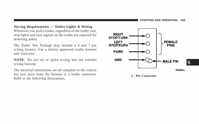
Towing Requirements — Trailer Lights & WiringWhenever you pull a trailer, regardless of the trailer size,stop lights and turn signals on the trailer are required formotoring safety.
The Trailer Tow Package may include a 4 and 7 pinwiring harness. Use a factory approved trailer harnessand connector.
NOTE: Do not cut or splice wiring into the vehicleswiring harness.
The electrical connections are all complete to the vehiclebut you must mate the harness to a trailer connector.Refer to the following illustrations.
4 - Pin Connector
STARTING AND OPERATING 343
5
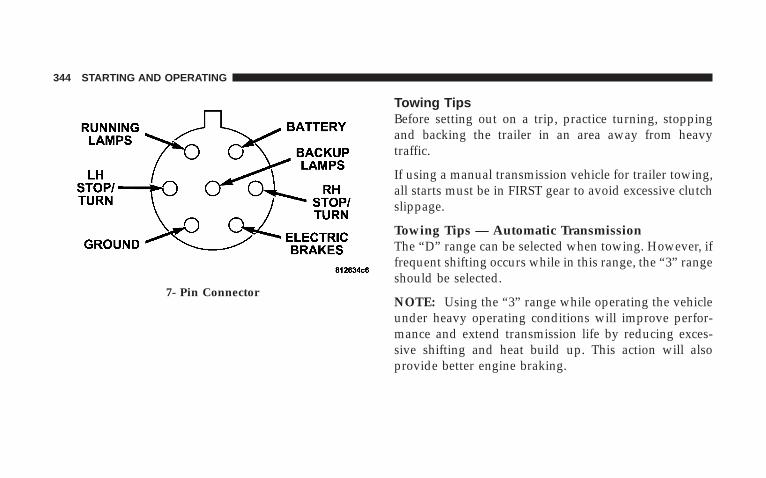
Towing TipsBefore setting out on a trip, practice turning, stoppingand backing the trailer in an area away from heavytraffic.
If using a manual transmission vehicle for trailer towing,all starts must be in FIRST gear to avoid excessive clutchslippage.
Towing Tips — Automatic TransmissionThe “D” range can be selected when towing. However, iffrequent shifting occurs while in this range, the “3” rangeshould be selected.
NOTE: Using the “3” range while operating the vehicleunder heavy operating conditions will improve perfor-mance and extend transmission life by reducing exces-sive shifting and heat build up. This action will alsoprovide better engine braking.
7- Pin Connector
344 STARTING AND OPERATING
The automatic transmission fluid and filter should bechanged if you REGULARLY tow a trailer for more than45 minutes of continuous operation. See “Schedule B” insection 8 of this manual for transmission fluid changeintervals.
NOTE: Check the automatic transmission fluid levelbefore towing.
Towing Tips — O/D Off (If Equipped)To reduce potential for automatic transmission overheat-ing, turn the “O/D OFF” feature OFF when driving inhilly areas or shift the transmission to Drive position 2 onmore severe grades. Refer to “Transmission Shifting” inthis section.
Towing Tips — Electronic Speed Control (IfEquipped)
− Don’t use in hilly terrain or with heavy loads.
− When using the speed control, if you experience speeddrops greater than 10 mph (16 km/h), disengage untilyou can get back to cruising speed.
− Use speed control in flat terrain and with light loads tomaximize fuel efficiency.
Towing Tips — Cooling SystemTo reduce potential for engine and transmission over-heating, take the following actions:
− Highway DrivingReduce speed.
− Air ConditioningTurn off temporarily.
− refer to Cooling System Operating information in theMaintenance section of this manual for more informa-tion.
STARTING AND OPERATING 345
5

RECREATIONAL TOWING (BEHINDMOTORHOME, ETC.)
CAUTION!
Front or rear wheel lifts should not be used. Internaldamage to the transmission or transfer case will occurif a front or rear wheel lift is used when recreationaltowing.
Towing – 2WD Models
Recreational towing is allowed ONLY if the rear drive-shaft is removed. See your authorized dealer or refer tothe Service Manual. Towing with the rear wheels on theground while the driveshaft is connected can result insevere transmission damage.
Towing – 4WD Models
NOTE: The transfer case must be shifted into N (Neu-tral) for recreational towing.
Shifting Into Neutral (N)Use the following procedure to prepare your vehicle forrecreational towing.
CAUTION!
It is necessary to follow these steps to be certain thatthe transfer case is fully in N (Neutral) before recre-ational towing to prevent damage to internal parts.
1. Depress brake pedal.
2. Shift automatic transmission into N (Neutral) or de-press clutch pedal on manual transmission.
3. Shift transfer case lever into N (Neutral).
346 STARTING AND OPERATING
4. Start engine.
5. Shift automatic transmission into D (Drive) or manualtransmission into gear.
6. Release brake pedal and ensure that there is no vehiclemovement.
7. Shut the engine off and place the ignition key into theACC position.
8. Shift automatic transmission into P (Park).
9. Apply parking brake.
10. Attach vehicle to the tow vehicle with tow bar.
11. Release parking brake.
12. Disconnect the negative battery cable, and secure itaway from the negative battery post.
CAUTION!
Damage to the transmission may occur if the trans-mission is shifted into P (Park) with the transfer casein N (Neutral) and the engine running. With thetransfer case in N (Neutral) ensure that the engine isoff prior to shifting the transmission into P (Park)(refer to steps 7 – 8 above).
Shifting Out Of Neutral (N)
Use the following procedure to prepare your vehicle fornormal usage.
1. Shift automatic transmission into N (Neutral) or de-press clutch pedal on manual transmission.
2. Shift transfer case lever into desired position.
STARTING AND OPERATING 347
5

3. Shift automatic transmission into D (Drive) or releaseclutch on manual transmissions.
NOTE: When shifting out of transfer case N (Neutral)on automatic transmission equipped vehicles, turningthe engine off may be required to avoid gear clash.
WARNING!
You or others could be injured if you leave thevehicle unattended with the transfer case in the N(Neutral) position without first fully engaging theparking brake. The transfer case N (Neutral) positiondisengages both the front and rear driveshafts fromthe powertrain and will allow the vehicle to movedespite the transmission position. The parking brakeshould always be applied when the driver is not inthe vehicle.
CAUTION!
• Do not use a bumper mounted clamp-on tow baron your vehicle. The bumper face bar will bedamaged.
348 STARTING AND OPERATING
WHAT TO DO IN EMERGENCIES
CONTENTS
� Hazard Warning Flashers . . . . . . . . . . . . . . . . . 350
� If Your Engine Overheats . . . . . . . . . . . . . . . . . 351
� Jacking And Tire Changing . . . . . . . . . . . . . . . . 352
▫ Jack Location . . . . . . . . . . . . . . . . . . . . . . . . 352
▫ Spare Tire Stowage . . . . . . . . . . . . . . . . . . . . 353
▫ Preparations For Jacking . . . . . . . . . . . . . . . . 353
▫ Jacking Instructions . . . . . . . . . . . . . . . . . . . . 354
� Jump Starting . . . . . . . . . . . . . . . . . . . . . . . . . 356
� Emergency Tow Hooks — If Equipped . . . . . . . . 358
� Towing A Disabled Vehicle . . . . . . . . . . . . . . . . 359
6
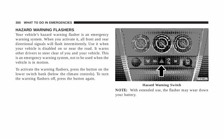
HAZARD WARNING FLASHERSYour vehicle’s hazard warning flasher is an emergencywarning system. When you activate it, all front and reardirectional signals will flash intermittently. Use it whenyour vehicle is disabled on or near the road. It warnsother drivers to steer clear of you and your vehicle. Thisis an emergency warning system, not to be used when thevehicle is in motion.
To activate the warning flashers, press the button on thelower switch bank (below the climate controls). To turnthe warning flashers off, press the button again.
NOTE: With extended use, the flasher may wear downyour battery.
Hazard Warning Switch
350 WHAT TO DO IN EMERGENCIES
IF YOUR ENGINE OVERHEATSIn any of the following situations, you can reduce thepotential for overheating by taking the appropriate ac-tion.
• On the highways — Slow down.
• In city traffic — While stopped, put transmission in N(Neutral), but do not increase engine idle speed.
NOTE: There are steps that you can take to slow downan impending overheat condition. If your air conditioneris on, turn it off. The air conditioning system adds heat tothe engine cooling system and turning off the A/Cremoves this heat. You can also turn the TemperatureControl to maximum heat, the Mode Control to floor, andthe Fan Control to High. This allows the heater core to actas a supplement to the radiator and aids in removing heatfrom the engine cooling system.
CAUTION!
Driving with a hot cooling system could damageyour vehicle. If the temperature gauge reads “H”,pull over and stop the vehicle. Idle the vehicle withthe air conditioner turned off until the pointer dropsback into the normal range. If the pointer remains onthe “H”, and you hear continuous chimes, turn theengine off immediately, and call for service.
WHAT TO DO IN EMERGENCIES 351
6
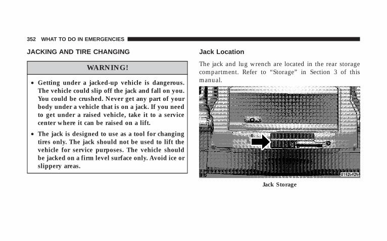
JACKING AND TIRE CHANGING
WARNING!
• Getting under a jacked-up vehicle is dangerous.The vehicle could slip off the jack and fall on you.You could be crushed. Never get any part of yourbody under a vehicle that is on a jack. If you needto get under a raised vehicle, take it to a servicecenter where it can be raised on a lift.
• The jack is designed to use as a tool for changingtires only. The jack should not be used to lift thevehicle for service purposes. The vehicle shouldbe jacked on a firm level surface only. Avoid ice orslippery areas.
Jack Location
The jack and lug wrench are located in the rear storagecompartment. Refer to “Storage” in Section 3 of thismanual.
Jack Storage
352 WHAT TO DO IN EMERGENCIES
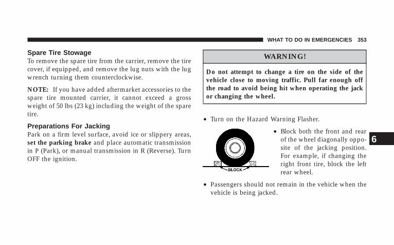
Spare Tire StowageTo remove the spare tire from the carrier, remove the tirecover, if equipped, and remove the lug nuts with the lugwrench turning them counterclockwise.
NOTE: If you have added aftermarket accessories to thespare tire mounted carrier, it cannot exceed a grossweight of 50 lbs (23 kg) including the weight of the sparetire.
Preparations For JackingPark on a firm level surface, avoid ice or slippery areas,set the parking brake and place automatic transmissionin P (Park), or manual transmission in R (Reverse). TurnOFF the ignition.
WARNING!
Do not attempt to change a tire on the side of thevehicle close to moving traffic. Pull far enough offthe road to avoid being hit when operating the jackor changing the wheel.
• Turn on the Hazard Warning Flasher.
• Block both the front and rearof the wheel diagonally oppo-site of the jacking position.For example, if changing theright front tire, block the leftrear wheel.
• Passengers should not remain in the vehicle when thevehicle is being jacked.
WHAT TO DO IN EMERGENCIES 353
6

Jacking Instructions
1. Remove spare tire, jack and tools from stored location.
2. Loosen (but do not remove) the wheel lug nuts byturning them to the left one turn while the wheel is stillon the ground.
3. Assemble the jack and jacking tools. Connect jackhandle driver to extension, then to lug wrench.
4. Operate jack from the front or the rear of the vehicle.Place the jack under the axle tube, as shown. Do not raisethe vehicle until you are sure the jack is fully engaged.
5. Raise the vehicle by turning the jack screw to the right.Raise the vehicle only until the tire just clears the surfaceand enough clearance is obtained to install the spare tire.Minimum tire lift provides maximum stability.
Jacking Locations
354 WHAT TO DO IN EMERGENCIES

WARNING!
Raising the vehicle higher than necessary can makethe vehicle less stable and cause an accident. It couldslip off the jack and hurt someone near it. Raise thevehicle only enough to remove the tire.
6. Remove the lug nuts and wheel.
7. Position spare wheel/tire on vehicle and install lugnuts with cone-shaped end toward wheel. Lightly tightennuts clockwise. To avoid the risk of forcing the vehicle offthe jack, do not tighten the nuts fully until the vehicle hasbeen lowered.
8. Lower the vehicle by turning the jack screw to the left,and remove the jack and wheel blocks.
9. Finish tightening the lug nuts. Push down on thewrench while tightening for increased leverage. Alternate
nuts until each nut has been tightened twice. Correctwheel nut tightness is 130 N·m (95 ft. lbs). If in doubtabout the correct tightness, have them checked with atorque wrench by your authorized dealer or at a servicestation.
10. Remove jack assembly and wheel blocks.
WARNING!
A loose tire or jack, thrown forward in a collision orhard stop could endanger the occupants of the ve-hicle. Always stow the jack parts and the spare tire inthe places provided.
11. Secure the tire, jack, and tools in their proper loca-tions.
WHAT TO DO IN EMERGENCIES 355
6
JUMP STARTINGIf the vehicle has a discharged battery, booster cables maybe used to obtain a start from a booster battery or thebattery in another vehicle. This type of start can be danger-ous if done improperly, so follow this procedure carefully.
WARNING!
Battery fluid is a corrosive acid solution; do not allowbattery fluid to contact eyes, skin or clothing. Don’t leanover battery when attaching clamps or allow the clampsto touch each other. If acid splashes in eyes or on skin,flush contaminated area immediately with large quan-tities of water.
A battery generates hydrogen gas which is flammableand explosive. Keep flame or spark away from the ventholes.
Do not use a booster battery or any other booster sourcethat has a greater than 12 volt system, i.e. Do not use a 24volt power source.
1. Remove all metal jewelry such as watch bands orbracelets which might make an unintended electricalcontact.
2. Park the booster vehicle within cable reach but with-out letting the vehicles touch. Set the parking brake onboth vehicles, place the automatic transmission in P(Park), or the manual transmission in N (Neutral), andturn the ignition OFF.
3. Turn off the heater, radio, and all unnecessary electri-cal loads.
4. Connect one end of a jumper cable to the positiveterminal of the booster battery. Connect the other end ofthe same cable to the positive terminal of the dischargedbattery.
356 WHAT TO DO IN EMERGENCIES
WARNING!
Do not permit vehicles to touch each other as thiscould establish a ground connection and personalinjury could result.
5. Connect the other cable, first to the negative terminalof the booster battery and then to the engine of thevehicle with the discharged battery. Make sure you havea good contact on the engine.
WARNING!
• You should not try to start your vehicle by pushingor towing.
• Do not connect the cable to the negative post of thedischarge battery. The resulting electrical sparkcould cause the battery to explode.
• During cold weather when temperatures are be-low freezing point, electrolyte in a dischargedbattery may freeze. Do not attempt jump startingbecause the battery could rupture or explode. Thebattery temperature must be brought up abovefreezing point before attempting jump start.
WHAT TO DO IN EMERGENCIES 357
6
6. Start the engine in the vehicle which has the boosterbattery, let the engine idle a few minutes, then start theengine in the vehicle with the discharged battery.
7. When removing the jumper cables, reverse the abovesequence exactly. Be careful of the moving belts and fan.
WARNING!
Any procedure other than above could result in:
1. Personal injury caused by electrolyte squirting outthe battery vent;
2. Personal injury or property damage due to batteryexplosion;
3. Damage to charging system of booster vehicle orof immobilized vehicle.
EMERGENCY TOW HOOKS — IF EQUIPPEDIf your vehicle is equipped with tow hooks, they aremounted in the front and the rear.
CAUTION!
Tow hooks are for emergency use only, to rescue avehicle stranded off road. Do not use tow hooks fortow truck hookup or highway towing. You coulddamage your vehicle. Tow straps are recommendedwhen towing the vehicle, chains may cause vehicledamage.
358 WHAT TO DO IN EMERGENCIES
WARNING!
Stand clear of vehicles when pulling with tow hooks.Tow straps and chains may break, causing seriousinjury.
TOWING A DISABLED VEHICLEThe manufacturer recommends towing with all fourwheels OFF the ground. Acceptable methods are to towthe vehicle on a flatbed or with one end of the vehicleraised and the other end on a towing dolly.
WHAT TO DO IN EMERGENCIES 359
6

MAINTAINING YOUR VEHICLE
CONTENTS
� Engine Compartment – 3.8L . . . . . . . . . . . . . . . 364
� Onboard Diagnostic System — OBD II . . . . . . . . 365
▫ Loose Fuel Filler Cap Message . . . . . . . . . . . . 366
� Emissions Inspection And MaintenancePrograms . . . . . . . . . . . . . . . . . . . . . . . . . . . . 366
� Replacement Parts . . . . . . . . . . . . . . . . . . . . . . 368
� Dealer Service . . . . . . . . . . . . . . . . . . . . . . . . . 368
� Maintenance Procedures . . . . . . . . . . . . . . . . . . 369
▫ Engine Oil . . . . . . . . . . . . . . . . . . . . . . . . . . 369
▫ Drive Belts — Check Condition And Tension . . 372
▫ Spark Plugs . . . . . . . . . . . . . . . . . . . . . . . . . 373
▫ Catalytic Converter . . . . . . . . . . . . . . . . . . . . 373
▫ Crankcase Emission Control System . . . . . . . . 375
▫ Fuel Filter . . . . . . . . . . . . . . . . . . . . . . . . . . 375
▫ Engine Air Cleaner Filter . . . . . . . . . . . . . . . . 375
▫ Maintenance-Free Battery . . . . . . . . . . . . . . . . 376
▫ Air Conditioner Maintenance . . . . . . . . . . . . . 376
▫ Power Steering Fluid Check . . . . . . . . . . . . . . 377
7
▫ Driveline And Steering ComponentLubrication . . . . . . . . . . . . . . . . . . . . . . . . . . 378
▫ Body Lubrication . . . . . . . . . . . . . . . . . . . . . 378
▫ Windshield Wiper Blades . . . . . . . . . . . . . . . . 379
▫ Windshield Washers . . . . . . . . . . . . . . . . . . . 379
▫ Exhaust System . . . . . . . . . . . . . . . . . . . . . . 380
▫ Cooling System . . . . . . . . . . . . . . . . . . . . . . . 380
▫ Hoses And Vacuum/Vapor Harnesses . . . . . . . 385
▫ Brake System . . . . . . . . . . . . . . . . . . . . . . . . 386
▫ Automatic Transmission . . . . . . . . . . . . . . . . 388
▫ Hydraulic Clutch Fluid — ManualTransmission . . . . . . . . . . . . . . . . . . . . . . . . 390
▫ Manual Transmission . . . . . . . . . . . . . . . . . . 390
▫ Transfer Case . . . . . . . . . . . . . . . . . . . . . . . . 391
▫ Front/Rear Axle Fluid . . . . . . . . . . . . . . . . . . 392
▫ Appearance Care And Protection FromCorrosion . . . . . . . . . . . . . . . . . . . . . . . . . . . 393
� Fuses (Totally Integrated Power Module) . . . . . . 400
� Vehicle Storage . . . . . . . . . . . . . . . . . . . . . . . . 407
� Replacement Bulbs — If Equipped . . . . . . . . . . . 408
� Bulb Replacement . . . . . . . . . . . . . . . . . . . . . . 409
▫ Head Light . . . . . . . . . . . . . . . . . . . . . . . . . . 409
▫ Front Park/Turn Signal . . . . . . . . . . . . . . . . . 410
▫ Front Side Marker . . . . . . . . . . . . . . . . . . . . . 410
▫ Front Fog Light . . . . . . . . . . . . . . . . . . . . . . 410
▫ Rear Tail, Stop, Turn Signal, And Back-UpLights . . . . . . . . . . . . . . . . . . . . . . . . . . . . . 411
▫ Center High Mounted Stop Light (CHMSL) . . . 411
362 MAINTAINING YOUR VEHICLE
� Fluid Capacities . . . . . . . . . . . . . . . . . . . . . . . . 412
� Fluids, Lubricants And Genuine Parts . . . . . . . . 413
▫ Engine . . . . . . . . . . . . . . . . . . . . . . . . . . . . . 413
▫ Chassis . . . . . . . . . . . . . . . . . . . . . . . . . . . . 414
MAINTAINING YOUR VEHICLE 363
7
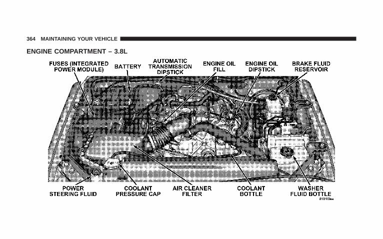
ENGINE COMPARTMENT – 3.8L
364 MAINTAINING YOUR VEHICLE
ONBOARD DIAGNOSTIC SYSTEM — OBD IIYour vehicle is equipped with a sophisticated onboarddiagnostic system called OBD II. This system monitorsthe performance of the emissions, engine, and automatictransmission control systems. When these systems areoperating properly, your vehicle will provide excellentperformance and fuel economy, as well as engine emis-sions well within current government regulations.
If any of these systems require service, the OBD II systemwill turn on the “Malfunction Indicator Light.” It willalso store diagnostic codes and other information toassist your service technician in making repairs. Al-though your vehicle will usually be drivable and notneed towing, see your dealer for service as soon aspossible.
CAUTION!
• Prolonged driving with the “Malfunction Indica-tor Light” on could cause further damage to theemission control system. It could also affect fueleconomy and driveability. The vehicle must beserviced before any emissions tests can be per-formed.
• If the “Malfunction Indicator Light” is flashingwhile the engine is running, severe catalytic con-verter damage and power loss will soon occur.Immediate service is required.
MAINTAINING YOUR VEHICLE 365
7
Loose Fuel Filler Cap MessageAfter fuel is added, the vehicle diagnostic system candetermine if the fuel filler cap is possibly loose, improp-erly installed, or damaged. A loose fuel filler cap messagewill be displayed in the instrument cluster. Tighten thegas cap until a �clicking� sound is heard. This is anindication that the gas cap is properly tightened. Pressthe odometer reset button to turn the message off. If theproblem persists, the message will appear the next timethe vehicle is started. This might indicate a damaged cap.If the problem is detected twice in a row, the system willturn on the Malfunction Indicator Light (MIL). Resolvingthe problem will turn the MIL light off.
EMISSIONS INSPECTION AND MAINTENANCEPROGRAMSIn some localities, it may be a legal requirement to passan inspection of your vehicle’s emissions control system.Failure to pass could prevent vehicle registration.
For states, which have an I/M (Inspection andMaintenance) requirement, this check verifies thefollowing: the MIL (Malfunction Indicator Light)
is functioning and is not on when the engine is running,and that the OBD (On Board Diagnostic) system is readyfor testing.
Normally, the OBD system will be ready. The OBDsystem may not be ready if your vehicle was recentlyserviced, if you recently had a dead battery, or a batteryreplacement. If the OBD system should be determinednot ready for the I/M test, your vehicle may fail the test.
366 MAINTAINING YOUR VEHICLE
Your vehicle has a simple ignition key actuated test,which you can use prior to going to the test station. Tocheck if your vehicle’s OBD system is ready, you must dothe following:
1. Insert your ignition key into the ignition switch.
2. Turn the ignition to the ON position, but do not crankor start the engine.
3. If you crank or start the engine, you will have to startthis test over.
4. As soon as you turn your key to the ON position, youwill see your MIL symbol come on as part of a normalbulb check.
5. Approximately 15 seconds later, one of two things willhappen:
a. The MIL will flash for about 10 seconds and thenreturn to being fully illuminated until you turn off the
ignition key or start the engine. This means that yourvehicle’s OBD system is not ready and you should notproceed to the I/M station.
b. The MIL will not flash at all and will remain fullyilluminated until you turn off the ignition key or startthe engine. This means that your vehicle’s OBD systemis ready and you can proceed to the I/M station.
If your OBD system is not ready, you should see yourauthorized dealer or repair facility. If your vehicle wasrecently serviced or had a battery failure or replacement,you may need to do nothing more than drive yourvehicle as you normally would in order for your OBDsystem to update. A recheck with the above test routinemay then indicate that the system is now ready.
Regardless of whether your vehicle’s OBD system isready or not ready, if the MIL symbol is illuminatedduring normal vehicle operation, you should have your
MAINTAINING YOUR VEHICLE 367
7
vehicle serviced before going to the I/M station. The I/Mstation can fail your vehicle because the MIL symbol is onwith the engine running.
REPLACEMENT PARTSUse of genuine Mopar� parts for normal/scheduledmaintenance and repairs is highly recommended to in-sure the designed performance. Damage or failurescaused by the use of non-Mopar� parts for maintenanceand repairs will not be covered by the manufacturer’swarranty.
DEALER SERVICEYour dealer has the qualified service personnel, specialtools, and equipment to perform all service operations inan expert manner. Service Manuals are available whichinclude detailed service information for your vehicle.Refer to these manuals before attempting any procedureyourself.
NOTE: Intentional tampering with emissions controlsystems can result in civil penalties being assessedagainst you.
WARNING!
You can be badly injured working on or around amotor vehicle. Only do service work for which youhave the knowledge and the proper equipment. Ifyou have any doubt about your ability to perform aservice job, take your vehicle to a competentmechanic.
368 MAINTAINING YOUR VEHICLE
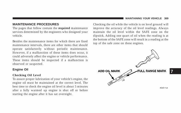
MAINTENANCE PROCEDURESThe pages that follow contain the required maintenanceservices determined by the engineers who designed yourvehicle.
Besides the maintenance items for which there are fixedmaintenance intervals, there are other items that shouldoperate satisfactorily without periodic maintenance.However, if a malfunction of these items does occur, itcould adversely affect the engine or vehicle performance.These items should be inspected if a malfunction isobserved or suspected.
Engine Oil
Checking Oil LevelTo assure proper lubrication of your vehicle’s engine, theengine oil must be maintained at the correct level. Thebest time to check the engine oil level is about 5 minutesafter a fully warmed up engine is shut off or beforestarting the engine after it has sat overnight.
Checking the oil while the vehicle is on level ground willimprove the accuracy of the oil level readings. Alwaysmaintain the oil level within the SAFE zone on thedipstick. Adding one quart of oil when the reading is atthe bottom of the SAFE zone will result in a reading at thetop of the safe zone on these engines.
MAINTAINING YOUR VEHICLE 369
7
CAUTION!
Overfilling or underfilling the crankcase will causeaeration or loss of oil pressure. This could damageyour engine.
Change Engine OilRoad conditions as well as your kind of driving affect theinterval at which your oil should be changed. Check thefollowing to determine if any apply to you:
• Day or night temperatures are below 32°F (0°C)
• Stop and go driving
• Extensive engine idling
• Driving in dusty conditions
• Short trip driving of less than 10 miles (16.2 km)
• More than 50% of your driving is at sustained highspeeds during hot weather, above 90°F (32°C)
• Taxi, Police, or delivery service (commercial service)
• Trailer towing
• Off-road or desert driving
• If equipped for and operating with E–85 (ethanol) fuel
If ANY of these apply to you, then change your engine oilat every interval shown in schedule “B” of the “Mainte-nance Schedules” section of this manual.
If none of these apply to you, then change your engine oilat every interval shown on schedule “A” of the “Main-tenance Schedules” section of this manual
NOTE: Under no circumstances should oil change in-tervals exceed 6,000 miles (10 000 km) or 6 monthswhichever comes first.
370 MAINTAINING YOUR VEHICLE
Engine Oil SelectionFor best performance and maximum protection for allengines under all types of operating conditions, themanufacturer recommends engine oils that are API Cer-tified and meet the requirements of DaimlerChryslerMaterial Standard MS-6395.
American Petroleum Institute (API) Engine OilIdentification Symbol
This symbol means that the oil hasbeen certified by the AmericanPetroleum Institute (API). Themanufacturer only recommendsAPI Certified engine oils.
Engine Oil Viscosity (3.8L Engines)SAE 5W-20 engine oil is recommended for all operatingtemperatures. This engine oil improves low tempera-ture starting and vehicle fuel economy. Your engine oilfiller cap shows the recommended engine oil viscosityfor your vehicle.
Lubricants which do not have both, the engine oil certi-fication mark and the correct SAE viscosity grade num-ber should not be used.
Materials Added To Engine OilsThe manufacturer strongly recommends against the ad-dition of any additives (other than leak detection dyes) toengine oil. Engine oil is an engineered product and it’sperformance may be impaired by supplemental addi-tives.
Disposing of Used Engine OilCare should be taken in disposing of used engine oil fromyour vehicle. Used oil, indiscriminately discarded, can
MAINTAINING YOUR VEHICLE 371
7

present a problem to the environment. Contact yourauthorized dealer, service station, or governmentalagency for advice on how and where used oil can besafely discarded in your area.
Engine Oil FilterThe engine oil filter should be replaced at every engineoil change.
Engine Oil Filter SelectionAll of the manufacturer’s engines have a full-flow typedisposable oil filter. Use a filter of this type for replace-ment. The quality of replacement filters varies consider-ably. Only high quality filters should be used to assuremost efficient service. Mopar� engine oil filters are highquality oil filters and are recommended.
Drive Belts — Check Condition and TensionBelt tension is controlled by means of an automatictensioner. No belt tension adjustments are required.However, belt and belt tensioner condition should beinspected at the specified intervals, and replaced if re-quired. See your authorized dealer for service
At the mileage indicated in the appropriate “Mainte-nance Schedule”, all belts and tensioner should bechecked for condition. Improper belt tension can causebelt slippage and failure.
Belts should be inspected for evidence of cuts, cracks,glazing, or frayed cords and replaced if there is indicationof damage which could result in belt failure. Low gen-erator belt tension can cause battery failure.
Also check belt routing to make sure there is no interfer-ence between the belts and other engine components.
372 MAINTAINING YOUR VEHICLE
Spark PlugsSpark plugs must fire properly to assure engine perfor-mance and emission control. New plugs should be in-stalled at the mileage specified in the appropriate main-tenance chart. The entire set should be replaced if there isany malfunction due to a faulty spark plug.
Refer to the “Vehicle Emission Control Information” labelin the engine compartment for spark plug information.
Catalytic ConverterThe catalytic converter requires the use of unleaded fuelonly. Leaded gasoline will destroy the effectiveness of theconverter as an emission control device.
Under normal operating conditions, the catalytic con-verter will not require maintenance. However, it is im-portant to keep the engine properly tuned to assureproper catalyst operation and prevent possible catalystdamage.
CAUTION!
Damage to the catalytic converter can result if yourvehicle is not kept in proper operating condition. Inthe event of engine malfunction, particularly involv-ing engine misfire or other apparent loss of perfor-mance, have your vehicle serviced promptly. Contin-ued operation of your vehicle with a severemalfunction could cause the converter to overheat,resulting in possible damage to the converter andvehicle.
MAINTAINING YOUR VEHICLE 373
7
WARNING!
A hot exhaust system can start a fire if you park overmaterials that can burn. Such materials might begrass or leaves coming into contact with your exhaustsystem. Do not park or operate your vehicle in areaswhere your exhaust system can contact anything thatcan burn.
In unusual situations involving grossly malfunctioningengine operation, a scorching odor may suggest severeand abnormal catalyst overheating. If this occurs, stopthe vehicle, turn off the engine and allow it to cool.Service, including a tune up to manufacturer’s specifica-tions, should be obtained immediately.
To minimize the possibility of catalytic converter dam-age:
• Do not shut off the engine or interrupt the ignitionwhen the transmission is in gear and the vehicle is inmotion.
• Do not try to start the engine by pushing or towing thevehicle.
• Do not idle the engine with any spark plug wiresdisconnected or removed, such as when diagnostictesting.
• Do not idle the engine for prolonged periods duringvery rough idle or malfunctioning operating condi-tions.
• Do not allow vehicle to run out of fuel.
NOTE: Intentional tampering with emissions controlsystems can result in civil penalties being assessedagainst you.
374 MAINTAINING YOUR VEHICLE
Crankcase Emission Control SystemProper operation of this system depends on freedomfrom sticking or plugging due to deposits. As vehiclemileage builds up, the PCV valve and passages mayaccumulate deposits. If a valve is not working properly,replace it with a new valve. DO NOT ATTEMPT TOCLEAN THE OLD PCV VALVE!
Check ventilation hose for indication of damage orplugging deposits. Replace if necessary.
Fuel FilterA plugged fuel filter can cause hard starting or limit thespeed at which a vehicle can be driven. Should anexcessive amount of dirt accumulate in the fuel tank,frequent replacement of the fuel filter which is mountedin the fuel tank may be necessary.
Engine Air Cleaner FilterUnder normal driving conditions, replace the air filter atthe intervals shown on “Maintenance Schedule A.” If,however, you drive the vehicle frequently under dusty orsevere conditions, the filter element should be inspectedperiodically and replaced if necessary at the intervalsshown on “Maintenance Schedule B.”
WARNING!
The air cleaner can provide protection in the case ofengine backfire. Do not remove the air cleaner unlessit is necessary for repair or maintenance. Make surethat no one is near the engine compartment beforestarting the vehicle with the air cleaner removed.Failure to do so can result in serious personal injury.
MAINTAINING YOUR VEHICLE 375
7
Maintenance-Free BatteryYour vehicle is equipped with a maintenance-free battery.You will never have to add water, nor is periodic main-tenance required.
WARNING!
Battery posts, terminals, and related accessories con-tain lead and lead compounds. Always wash handsafter handling the battery.
CAUTION!
It is essential when replacing the cables on thebattery that the positive cable is attached to thepositive post and the negative cable is attached to thenegative post. Battery posts are marked (+) positiveand negative (-) and identified on the battery case.Also, if a “fast charger” is used while battery is in thevehicle, disconnect both vehicle battery cables beforeconnecting the charger to battery. Do not use a “fastcharger” to provide starting voltage.
Air Conditioner MaintenanceFor best possible performance, your air conditionershould be checked and serviced by an Authorized Dealerat the start of each warm season. This service should
376 MAINTAINING YOUR VEHICLE
include cleaning of the condenser fins and a performancetest. Drive belt tension should also be checked at thistime.
WARNING!
• Use only refrigerants and compressor lubricantsapproved by the manufacturer for your air condi-tioning system. Some unapproved refrigerants areflammable and can explode, injuring you. Otherunapproved refrigerants or lubricants can causethe system to fail, requiring costly repairs. Refer toSection 3 of the Warranty Information Book foradditional warranty information.
• The air conditioning system contains refrigerantunder high pressure. To avoid risk of personalinjury or damage to the system, adding refrigerantor any repair requiring lines to be disconnectedshould be done by an experienced repairman.
Refrigerant Recovery and RecyclingR-134a Air Conditioning Refrigerant is a hydrofluorocar-bon (HFC) that is endorsed by the Environmental Pro-tection Agency and is an ozone-saving product. How-ever, the manufacturer recommends that air conditioningservice be performed by dealers or other service facilitiesusing recovery and recycling equipment.
Power Steering Fluid CheckChecking the power steering fluid level at a definedservice interval is not required. The fluid should only bechecked if a leak is suspected, abnormal noises areapparent, and/or the system is not functioning as antici-pated. Coordinate inspection efforts through a certifiedDaimlerChrysler Dealership.�
MAINTAINING YOUR VEHICLE 377
7
WARNING!
Fluid level should be checked on a level surface withthe engine off to prevent injury from moving parts,and to insure accurate fluid level reading. Do notoverfill. Use only the manufacturer’s recommendedfluid.
If necessary, add fluid to restore to the proper indicatedlevel. With a clean cloth, wipe any spilled fluid from allsurfaces. Refer to Fluids, Lubricants, and Genuine Partsfor correct fluid type.
NOTE: Upon initial start-up in cold weather, the powersteering pump may make noise for a short period of time.This is due to the cold, thick fluid in the steering system.This noise should be considered normal, and does not inany way damage the steering system.
Driveline And Steering Component LubricationAll driveline and steering components are sealed and donot require lubrication. Driveshafts are not serviceable.
Body LubricationLocks and all body pivot points, including such items asseat tracks, doors, tailgate and hood hinges, should belubricated periodically to assure quiet, easy operationand to protect against rust and wear. Prior to the appli-cation of any lubricant, the parts concerned should bewiped clean to remove dust and grit; after lubricatingexcess oil and grease should be removed. Particularattention should also be given to hood latching compo-nents to insure proper function. When performing otherunderhood services, the hood latch, release mechanismand safety catch should be cleaned and lubricated.
The external lock cylinders should be lubricated twice ayear, preferably in the fall and spring. Apply a small
378 MAINTAINING YOUR VEHICLE
amount of a high quality lubricant such as Mopar� LockCylinder Lubricant directly into the lock cylinder.
Windshield Wiper BladesClean the rubber edges of the wiper blades and thewindshield periodically with a sponge or soft cloth and amild non-abrasive cleaner. This will remove accumula-tions of salt or road film.
Operation of the wipers on dry glass for long periodsmay cause deterioration of the wiper blades. Always usewasher fluid when using the wipers to remove salt or dirtfrom a dry windshield. Avoid using the wiper blades toremove frost or ice from the windshield. Keep the bladerubber out of contact with petroleum products such asengine oil, gasoline, etc.
Windshield WashersThe fluid reservoir in the engine compartment should bechecked for fluid level at regular intervals. Fill thereservoir with windshield antifreeze (not radiator anti-freeze) rated not to freeze at -25°F (-31°C). Operate thesystem for a few seconds to flush out the residual water.
WARNING!
Commercial windshield washer solvents are flam-mable. They could ignite and burn you. Care must beexercised when filling or working around the washersolution.
MAINTAINING YOUR VEHICLE 379
7
Exhaust SystemThe best protection against carbon monoxide entry intothe vehicle body is a properly maintained engine exhaustsystem.
If you notice a change in the sound of the exhaust system;or if the exhaust fumes can be detected inside the vehicle;or when the underside or rear of the vehicle is damaged;have an authorized technician inspect the complete ex-haust system and adjacent body areas for broken, dam-aged, deteriorated, or mispositioned parts. Open seamsor loose connections could permit exhaust fumes to seepinto the passenger compartment. In addition, inspect theexhaust system each time the vehicle is raised for lubri-cation or oil change. Replace as required.
Cooling System
WARNING!
You or others can be badly burned by hot antifreeze/coolant or steam from your radiator. If you see or hearsteam coming from under the hood, don’t open thehood until the radiator has had time to cool. Nevertry to open a cooling system pressure cap when theradiator or coolant bottle is hot.
Engine Coolant ChecksCheck antifreeze/coolant protection every 12 months(before the onset of freezing weather, where applicable).If antifreeze/coolant is dirty or rusty in appearance, thesystem should be drained, flushed and refilled with freshantifreeze/coolant. Check the front of the A/C condenser(if equipped) or radiator for any accumulation of bugs,leaves, etc. If dirty, clean by gently spraying water from a
380 MAINTAINING YOUR VEHICLE
garden hose vertically down the face of the A/C con-denser (if equipped) or the back of the radiator core.
Check the engine cooling system hoses for brittle rubber,cracking, tears, cuts, and tightness of the connection atthe coolant recovery bottle and radiator. Inspect theentire system for leaks.
With the engine at normal operating temperature (butnot running), check the cooling system pressure cap forproper vacuum sealing by draining a small amount ofantifreeze/coolant from the radiator drain cock. If the capis sealing properly, the antifreeze/coolant will begin todrain from the coolant recovery bottle. DO NOT RE-MOVE THE COOLANT PRESSURE CAP WHEN THECOOLING SYSTEM IS HOT.
Cooling System — Drain, Flush, And RefillAt the intervals shown in the appropriate “MaintenanceSchedule,” the system should be drained, flushed, andrefilled.
If the solution is dirty and contains a considerableamount of sediment, clean and flush with reliable coolingsystem cleaner. Follow with a thorough rinsing to removeall deposits and chemicals. Properly dispose of oldantifreeze/coolant solution.
Discard old antifreeze/coolant solution according to rec-ommended procedure.
Selection Of Engine CoolantUse only the manufacturer’s recommended antifreeze/coolant, refer to Fluids, Lubricants, and Genuine Parts forcorrect antifreeze/coolant type.
MAINTAINING YOUR VEHICLE 381
7
CAUTION!
• Mixing of antifreeze/coolant other than the speci-fied HOAT antifreeze/coolant may result in de-creased corrosion protection and engine damage.If a non-HOAT antifreeze/coolant is introducedinto the cooling system in an emergency, it shouldbe replaced with the specified antifreeze/coolantas soon as possible.
• Do not use plain water alone or alcohol baseantifreeze/coolant products. Do not use additionalrust inhibitors or antirust products, as they maynot be compatible with the antifreeze/coolant andmay plug the radiator.
• This vehicle has not been designed for use withPropylene Glycol based antifreeze/coolant. Use ofPropylene Glycol base antifreeze/coolant is notrecommended.
Adding Engine CoolantYour vehicle has been built with an improved antifreeze/coolant that allows extended maintenance intervals. Thisantifreeze/coolant can be used up to 5 Years or 100,000miles before replacement. To prevent reducing this ex-tended maintenance period, it is important that you usethe same antifreeze/coolant throughout the life of yourvehicle. Please review these recommendations for usingHybrid Organic Additive Technology (HOAT)antifreeze/coolant.
When adding antifreeze/coolant, a minimum solution of50% recommended Mopar Antifreeze/ Coolant 5 Year/100,000 Mile Formula HOAT (Hybrid Organic AdditiveTechnology), or equivalent, in water should be used. Usehigher concentrations (not to exceed 70%) if temperaturesbelow -34°F (-37°C) are anticipated.
382 MAINTAINING YOUR VEHICLE
Use only high purity water such as distilled or deionizedwater when mixing the water/antifreeze (coolant) solu-tion. The use of lower quality water will reduce theamount of corrosion protection in the engine coolingsystem.
Please note that it is the owner’s responsibility to main-tain the proper level of protection against freezing ac-cording to the temperatures occurring in the area wherethe vehicle is operated.
NOTE: Mixing antifreeze/coolant types will decreasethe life of the antifreeze/coolant and will require morefrequent antifreeze/coolant changes.
Cooling System Pressure CapThe cap must be fully tightened to prevent loss ofantifreeze/coolant, and to insure that antifreeze/coolantwill return to the radiator from the coolant reserve tank.
The cap should be inspected and cleaned if there is anyaccumulation of foreign material on the sealing surfaces.
WARNING!
The warning words DO NOT OPEN HOT on thecooling system pressure cap are a safety precaution.Never add antifreeze/coolant when the engine isoverheated. Do not loosen or remove the cap to coolan overheated engine. Heat causes pressure to buildup in the cooling system. To prevent scalding orinjury, do not remove the pressure cap while thesystem is hot or under pressure.
Disposal of Used Engine CoolantUsed ethylene glycol based antifreeze/coolant is a regu-lated substance requiring proper disposal. Check withyour local authorities to determine the disposal rules foryour community. To prevent ingestion by animals or
MAINTAINING YOUR VEHICLE 383
7
children, do not store ethylene glycol based antifreeze/coolant in open containers or allow it to remain inpuddles on the ground. If ingested by a child, contact aphysician immediately. Clean up any ground spills im-mediately.
Engine Coolant LevelThe coolant bottle provides a quick visual method fordetermining that the coolant level is adequate. With theengine idling, and warm to normal operating tempera-ture, the level of the antifreeze/coolant in the bottleshould be between the ranges indicated on the bottle.
The radiator normally remains completely full, so there isnot need to remove the radiator cap unless checking forantifreeze/coolant freeze point or replacing antifreeze/coolant. Advise your service attendant of this. As long asthe engine operating temperature is satisfactory, thecoolant bottle need only be checked once a month.
When additional antifreeze/coolant is needed to main-tain the proper level, it should be added to the coolantbottle. Do not overfill.
Points To Remember
NOTE: When the vehicle is stopped after a few miles ofoperation, you may observe vapor coming from the frontof the engine compartment. This is normally a result ofmoisture from rain, snow, or high humidity accumulat-ing on the radiator and being vaporized when thethermostat opens, allowing hot antifreeze/coolant toenter the radiator.
If an examination of your engine compartment shows noevidence of radiator or hose leaks, the vehicle may besafely driven. The vapor will soon dissipate.
• Do not overfill the coolant bottle.
• Check antifreeze/coolant freeze point in the radiatorand in the coolant recovery bottle. If antifreeze/
384 MAINTAINING YOUR VEHICLE
coolant needs to be added, contents of coolant recov-ery bottle must also be protected against freezing.
• If frequent antifreeze/coolant additions are required,or if the level in the recovery bottle does not dropwhen the engine cools, the cooling system should bepressure tested for leaks.
• Maintain antifreeze/coolant concentration at 50%HOAT antifreeze/coolant (minimum) and distilledwater for proper corrosion protection of your enginewhich contains aluminum components.
• Make sure that the radiator and coolant recoverybottle hoses are not kinked or obstructed.
• Keep the front of the radiator clean. If your vehicle isequipped with air conditioning, keep the front of thecondenser clean, also.
• Do not change the thermostat for summer or winteroperation. If replacement is ever necessary, install
ONLY the correct type thermostat. Other designs mayresult in unsatisfactory cooling performance, poor gasmileage, and increased emissions.
Hoses and Vacuum/Vapor HarnessesInspect surfaces of hoses and nylon tubing for evidenceof heat and mechanical damage. Hard or soft spots,brittle rubber, cracking, tears, cuts, abrasions, and exces-sive swelling indicate deterioration of the rubber.
Pay particular attention to the hoses nearest to high heatsources such as the exhaust manifold. Inspect hose rout-ing to be sure hoses do not touch any heat source ormoving component that may cause heat damage ormechanical wear.
Insure nylon tubing in these areas has not melted orcollapsed. Inspect all hose connections such as clampsand couplings to make sure they are secure and no leaks
MAINTAINING YOUR VEHICLE 385
7
are present. Components should be replaced immedi-ately if there is any evidence of degradation that couldcause failure.
Brake SystemIn order to assure brake system performance, all brakesystem components should be inspected periodically.Refer to the appropriate “Maintenance Schedule” inSection 8 for suggested service intervals.
WARNING!
Riding the brakes can lead to brake failure andpossibly an accident. Driving with your foot restingor riding on the brake pedal can result in abnormallyhigh brake temperatures, excessive lining wear, andpossible brake damage. You wouldn’t have your fullbraking capacity in an emergency.
Brake and Power Steering System HosesWhen servicing the vehicle for scheduled maintenance,inspect surface of hoses for evidence of heat and me-chanical damage. Hard and brittle rubber, cracking, tears,cuts, abrasion, and excessive swelling suggest deteriora-tion of the rubber. Particular attention should be made toexamining those hose surfaces nearest to high heatsources, such as the exhaust manifold.
Inspect all hose clamps and couplings to make sure theyare secure and no leaks are present.
NOTE: Inspection of brake hoses should be done when-ever the brake system is serviced and every engine oilchange.
386 MAINTAINING YOUR VEHICLE
WARNING!
Worn brake hoses can burst and cause brake failure.You could have an accident. If you see any signs ofcracking, scuffing, or worn spots, have the brakehoses replaced immediately.
Brake Master CylinderThe fluid level in the master cylinder should be checkedwhen performing under hood services, or immediately ifthe BRAKE warning light shows system failure
Be sure to clean the top of the master cylinder area beforeremoving the cap. If necessary, add fluid to bring thefluid level up to the requirements described on the brakefluid reservoir. With disc brakes, fluid level can beexpected to fall as the brake pads wear. Brake fluid level
should be checked when pads are replaced. However,low fluid level may be caused by a leak and a checkupmay be needed.
Use only manufacturer’s recommended brake fluid, referto Fluids, Lubricants, and Genuine Parts for correct fluidtype.
WARNING!
• Use of a brake fluid that may have a lower initialboiling point or unidentified as to specification,may result in sudden brake failure during hardprolonged braking. You could have an accident.
• Overfilling the brake fluid reservoir can result inspilling brake fluid on hot engine parts and thebrake fluid catching fire.
MAINTAINING YOUR VEHICLE 387
7
Use only brake fluid that has been in a tightly closedcontainer to avoid contamination from foreign matter. Donot allow petroleum base fluid to contaminate the brakefluid as seal damage will result.
Automatic Transmission
Selection of LubricantIt is important that the proper lubricant is used in thetransmission to assure optimum transmission perfor-mance. Use only manufacturer’s recommended transmis-sion fluid, refer to Fluids, Lubricants, and Genuine Partsfor correct fluid type. It is important that the transmissionfluid be maintained at the prescribed level using therecommended fluid.
CAUTION!
Using a transmission fluid other than the manufac-turer’s recommended fluid may cause deteriorationin transmission shift quality and/or torque convertershudder. Using a transmission fluid other than themanufacturer’s recommended fluid will result inmore frequent fluid and filter changes. Refer toFluids, Lubricants, and Genuine Parts for correctfluid type.
Fluid Level Check — 42RLE
NOTE: If equipped with a dipstick, use the followingprocedure. If your vehicle has a capped dipstick tube, itis sealed and should not be tampered with. Your autho-rized dealer has the proper tools to ensure that the fluidlevel is set properly.
388 MAINTAINING YOUR VEHICLE
Check the fluid level while the transmission is at normaloperating temperature 180° F (82° C). This occurs after atleast 15 mi (25 km) of driving. At normal operatingtemperature the fluid cannot be held comfortably be-tween the fingertips.
To properly check the automatic transmission fluid level,the following procedure must be used:
1. Operate the engine at idle speed and normal operatingtemperature.
2. The vehicle must be on level ground.
3. Fully apply parking brake.
4. Place the gear selector momentarily in each gearposition ending with the lever in P (Park).
5. Remove the dipstick, wipe it clean and reinsert it untilseated.
6. Remove the dipstick again and note the fluid level onboth sides. The fluid level should be between the HOT(upper) reference holes on the dipstick at normal operat-ing temperature. Verify that a solid coating of oil is seenon both sides of the dipstick. If the fluid is low, add asrequired into the dipstick tube. Do not overfill. Afteradding any quantity of oil through the dipstick tube, waita minimum of two (2) minutes for the oil to fully draininto the transmission before rechecking the fluid level.
NOTE: If it is necessary to check the transmission belowthe operating temperature, the fluid level should bebetween the two cold (lower) holes on the dipstick withthe fluid at approximately 70° F (21° C) (room tempera-ture). If the fluid level is correctly established at roomtemperature, it should be between the HOT (upper)reference holes when the transmission reaches 180° F (21°C). Remember it is best to check the level at the normaloperating temperature.
MAINTAINING YOUR VEHICLE 389
7
CAUTION!
Be aware that if the fluid temperature is below 50° F(10° C), it may not register on the dipstick. Do not addfluid until the temperature is elevated enough toproduce an accurate reading.
7. Check for leaks. Release the parking brake.
NOTE: To prevent dirt and water from entering thetransmission after checking or replenishing fluid, makecertain that the dipstick cap is properly reseated. It isnormal for the dipstick cap to spring back slightly fromits fully seated positions, as long as its seal remainsengaged in the dipstick tube.
Special AdditivesThe manufacturer strongly recommends against the ad-dition of any additives to the transmission. The onlyexception to this policy is the use of special dyes to aid indetecting fluid leaks. The use of transmission sealersshould be avoided as they may adversely affect seals.
Hydraulic Clutch Fluid — Manual TransmissionThe clutch hydraulic system is a sealed maintenance freesystem. In the event of leakage or other malfunction, thesystem must be replaced.
Manual Transmission
Selection of LubricantUse only manufacturer’s recommended manual trans-mission fluid, refer to Fluids, Lubricants, and GenuineParts for correct fluid type.
390 MAINTAINING YOUR VEHICLE
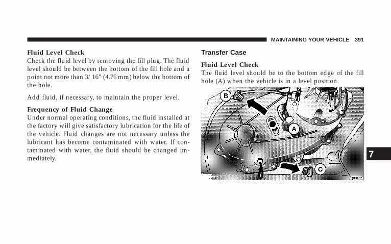
Fluid Level CheckCheck the fluid level by removing the fill plug. The fluidlevel should be between the bottom of the fill hole and apoint not more than 3/16” (4.76 mm) below the bottom ofthe hole.
Add fluid, if necessary, to maintain the proper level.
Frequency of Fluid ChangeUnder normal operating conditions, the fluid installed atthe factory will give satisfactory lubrication for the life ofthe vehicle. Fluid changes are not necessary unless thelubricant has become contaminated with water. If con-taminated with water, the fluid should be changed im-mediately.
Transfer Case
Fluid Level CheckThe fluid level should be to the bottom edge of the fillhole (A) when the vehicle is in a level position.
MAINTAINING YOUR VEHICLE 391
7

Adding FluidFluid should be added only at filler hole until fluidbegins to run out of the hole.
DrainFirst remove fill plug (B), then drain plug (C). Recom-mended tightening torque for drain and fill plugs is15–25 ft.lbs. (20–34 N·m).
CAUTION!
When replacing plugs, do not overtighten. You coulddamage them and cause them to leak.
Selection of LubricantUse only manufacturer’s recommended fluid, refer toFluids, Lubricants, and Genuine Parts for correct fluidtype.
Front/Rear Axle Fluid
Fluid Level CheckLubricant should be at bottom edge of the oil fill hole.
Adding FluidAdd lubricant only at the fill hole and only to the levelspecified above.
Selection of LubricantUse only manufacturer’s recommended fluid, refer toFluids, Lubricants, and Genuine Parts for correct fluidtype.
Maintenance After Off-Road DrivingAfter extended operation in mud, sand or water, orsimilar dirty conditions, have your brake drums, brakelinings, and axle joints inspected and cleaned as soon aspossible. This will prevent any abrasive material fromcausing excessive wear or unpredictable braking action.
392 MAINTAINING YOUR VEHICLE
Following off-road usage, completely inspect the under-body of your vehicle. Check tires, body structure, steer-ing, suspension and exhaust system for damage. Checkthreaded fasteners for looseness, particularly on thechassis, drivetrain components, steering and suspension.Retighten, if required, to torque values specified in theService Manual. Also check for accumulations of vegeta-tion or brush that could become a fire hazard, or concealdamage to fuel lines, brake hoses, axle pinion seals, andpropeller shafts. Check air conditioning drain tube on thelower dash wall in the engine compartment for mud ordebris, and clean as required. A plugged tube willadversely affect air conditioning performance.
CAUTION!
Under frequent heavy-duty driving conditions,change all lubricants, and lubricate body compo-nents more often than in normal service to preventexcessive wear.
Appearance Care And Protection From Corrosion
Protection Of Body And Paint From CorrosionVehicle body care requirements vary according to geo-graphic locations and usage. Chemicals that make roadspassable in snow and ice, and those that are sprayed ontrees and road surfaces during other seasons, are highlycorrosive to the metal in your vehicle. Outside parking,which exposes your vehicle to airborne contaminants,road surfaces on which the vehicle is operated, extreme
MAINTAINING YOUR VEHICLE 393
7
hot or cold weather and other extreme conditions willhave an adverse effect on paint, metal trim, and under-body protection.
The following maintenance recommendations will enableyou to obtain maximum benefit from the corrosionresistance built into your vehicle.
What Causes Corrosion?Corrosion is the result of deterioration or removal ofpaint and protective coatings from your vehicle.
The most common causes are:
• Road salt, dirt and moisture accumulation.
• Stone and gravel impact.
• Insects, tree sap and tar.
• Salt in the air near sea-coast localities.
• Atmospheric fallout/industrial pollutants.
• Bird droppings.
Washing
• Wash your vehicle regularly. Always wash your ve-hicle in the shade using Mopar� Car Wash or a mildcar wash soap, and rinse the panels completely withclear water.
• If insects, tar, or other similar deposits have accumu-lated on your vehicle, use Mopar� Super Kleen Bugand Tar Remover to remove.
• Use Mopar� Cleaner Wax to remove road film, stains,and to protect your paint finish. Take care never toscratch the paint.
• Avoid using abrasive compounds and power buffingthat may diminish the gloss or thin out the paintfinish.
394 MAINTAINING YOUR VEHICLE
CAUTION!
Do not use abrasive or strong cleaning materials suchas steel wool or scouring powder, which will scratchmetal and painted surfaces.
Special Care
• If you drive on salted or dusty roads or if you drivenear the ocean, hose off the undercarriage at least oncea month.
• It is important that the drain holes in the lower edgesof the doors, rocker panels and tailgate must be keptclear and open.
• If you detect any stone chips or scratches in the paint,touch them up immediately. The cost of such repairs isconsidered the responsibility of the owner.
• If your vehicle is damaged due to an accident orsimilar cause which destroys the paint and protectivecoating have your vehicle repaired as soon as possible.The cost of such repairs is considered the responsibil-ity of the owner.
• If you carry special cargo such as chemicals, fertilizers,de-icer salt, etc., assure that such materials are wellpackaged and sealed.
• If a lot of driving is done on gravel roads, considermud or stone shields behind each wheel.
• Use Mopar� Touch Up Paint on scratches or chips assoon as possible. Your authorized dealer has touch uppaint to match the color of your vehicle.
MAINTAINING YOUR VEHICLE 395
7
Wheel and Wheel Trim CareAll wheels and wheel trim, especially aluminum andchrome plated wheels should be cleaned regularly with amild soap and water to prevent corrosion. To removeheavy soil, use Mopar� Wheel Cleaner or select a non-abrasive, non-acidic cleaner. Do not use scouring pads,steel wool, a bristle brush or metal polishes. Only Mo-par� cleaners are recommended. Do not use oven cleaner.Avoid automatic car washes that use acidic solutions orharsh brushes that may damage the wheels’ protectivefinish.
YES Essentials� Fabric Cleaning Procedure – IfEquippedYES Essentials� seats may be cleaned in the followingmanner:
• Remove as much of the stain as possible by blottingwith a clean, dry towel.
• Blot any remaining stain with a clean, damp towel.
• For tough stains, apply Mopar� Total Clean or a mildsoap solution to a clean, damp cloth and remove stain.Use a fresh, damp towel to remove soap residue.
• For grease stains, apply Mopar� Multi-PurposeCleaner to a clean, damp cloth and remove stain. Usea fresh, damp towel to remove soap residue.
• Do not use any solvents or protectants on Yes Essen-tials� products.
Interior CareUse Mopar� Total Clean to clean fabric upholstery andcarpeting.
Interior Trim should be cleaned starting with a dampcloth, a damp cloth with Mopar� Total Clean, thenMopar� Spot & Stain Remover if absolutely necessary. Donot use harsh cleaners or Armorall. Use Mopar� TotalClean to clean vinyl upholstery.
396 MAINTAINING YOUR VEHICLE
WARNING!
Do not use volatile solvents for cleaning purposes.Many are potentially flammable, and if used inclosed areas they may cause respiratory harm.
Glass SurfacesAll glass surfaces should be cleaned on a regular basiswith Mopar� Glass Cleaner or any commercialhousehold-type glass cleaner. Never use an abrasive typecleaner. Use caution when cleaning inside rear windowsequipped with electric defrosters. Do not use scrapers orother sharp instruments which may scratch the elements.
When cleaning the rear view mirror, spray cleaner on thetowel or rag that you are using. Do not spray cleanerdirectly on the mirror.
Cleaning Plastic Instrument Cluster LensesThe lenses in front of the instruments in this vehicle aremolded in clear plastic. When cleaning the lenses, caremust be taken to avoid scratching the plastic.
1. Clean with a wet soft rag. A mild soap solution may beused, but do not use high alcohol content or abrasivecleaners. If soap is used, wipe clean with a clean damprag.
2. Dry with a soft tissue.
Seat Belt MaintenanceDo not bleach, dye or clean the belts with chemicalsolvents or abrasive cleaners. This will weaken the fabric.Sun damage will also weaken the fabric.
If the belts need cleaning, use Mopar� Total Clean, a mildsoap solution, or lukewarm water. Do not remove thebelts from the vehicle to wash them.
MAINTAINING YOUR VEHICLE 397
7
Replace the belts if they appear frayed or worn or if thebuckles do not work properly.
Appearance Care For Fabric Top Models
CAUTION!
To maintain the appearance of your vehicle’s interiortrim and top, follow these precautions:
• Avoid leaving your vehicle unattended with the topdown, as exposure to sun or rain may damage interiortrim.
• Do not use harsh cleaners or bleaching agents on topmaterial, as damage may result.
• Do not allow any vinyl cleaner to run down and dryon the paint, leaving a streak.
• After cleaning your vehicle’s fabric top, always makesure it is completely dry before lowering.
• Be especially careful when washing the windows byfollowing the directions for “Care of Fabric Top Win-dows.”
WASHING — Use Mopar� Car Wash or mild soap suds,lukewarm water, and a brush with soft bristles. If extracleaning is required, use Mopar� Convertible Cloth TopCleaner or a mild foaming cleaner on the entire top, butsupport top from underneath.
RINSING — Be sure to remove all trace of cleaner byrinsing the top thoroughly with clean water. Rememberto allow the top to dry before lowering it.
398 MAINTAINING YOUR VEHICLE
Care Of Fabric Top Windows
CAUTION!
Your vehicle’s fabric top has pliable plastic windowswhich can be scratched unless special care is taken byfollowing these directions:
1. Never use a dry cloth to remove dust. Instead, use amicrofiber towel or soft cotton cloth moistened withcold or warm, clean water, and wipe across the window,not up and down. Mopar� Jeep Soft Glass WindowCleaner will safely clean all plastic windows withoutscratching. Removes fine scratches to improve visibilityand provide UV protection to help prevent yellowing.
2. When washing, never use hot water or anythingstronger than a mild soap. Never use solvents such asalcohol or harsh cleaning agents.
3. Always rinse thoroughly with cold water, then wipewith a soft and slightly moist, clean cloth.
4. When removing frost, snow or ice, never use a scraperor de-icing chemicals. Use warm water only if you mustclean the window quickly.
5. Debris (sand, mud/dirt, dust, or salt) from off-roaddriving will have a major impact on zipper operation.Even normal on-road driving and vehicle washing willeventually impact window zipper operation. To maintainease of use of the window zippers, each window zippershould be cleaned and lubricated regularly. Use Mopar�Soft Top Zipper Cleaner and Lubricant to ease zipperoperation. Before applying, make sure the zipper teethare clear of sand, mud, and other materials. Clean bothsides of the zipper, not just one side. Rinse both zipperhalves with fresh water and allow to dry. Aggressivelywork the Mopar� Soft Top Zipper Cleaner and Lubricant
MAINTAINING YOUR VEHICLE 399
7
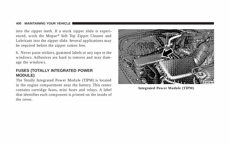
into the zipper teeth. If a stuck zipper slide is experi-enced, work the Mopar� Soft Top Zipper Cleaner andLubricant into the zipper slide. Several applications maybe required before the zipper comes free.
6. Never paste stickers, gummed labels or any tape to thewindows. Adhesives are hard to remove and may dam-age the windows.
FUSES (TOTALLY INTEGRATED POWERMODULE)The Totally Integrated Power Module (TIPM) is locatedin the engine compartment near the battery. This centercontains cartridge fuses, mini fuses and relays. A labelthat identifies each component is printed on the inside ofthe cover.
Integrated Power Module (TIPM)
400 MAINTAINING YOUR VEHICLE
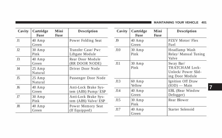
Cavity CartridgeFuse
MiniFuse
Description
J1 40 AmpGreen
Power Folding Seat
J2 30 AmpPink
Transfer Case/PwrLiftgate Module
J3 40 AmpGreen
Rear Door Module(RR DOOR NODE)
J4 25 AmpNatural
Driver Door Node
J5 25 AmpNatural
Passenger Door Node
J6 40 AmpGreen
Anti-Lock Brake Sys-tem (ABS) Pump/ESP
J7 30 AmpPink
Anti-Lock Brake Sys-tem (ABS) Valve/ESP
J8 40 AmpGreen
Power Memory Seat(If Equipped)
Cavity CartridgeFuse
MiniFuse
Description
J9 40 AmpGreen
PZEV Motor/FlexFuel
J10 30 AmpPink
Headlamp WashRelay/Manual TuningValve
J11 30 AmpPink
Sway Bar/THATCHAM Lock-Unlock/Power Slid-ing Door Module
J13 60 AmpYellow
Ignition Off Draw(IOD) — Main
J14 40 AmpGreen
EBL (Rear WindowDefogger)
J15 30 AmpPink
Rear Blower
J17 40 AmpGreen
Starter Solenoid
MAINTAINING YOUR VEHICLE 401
7
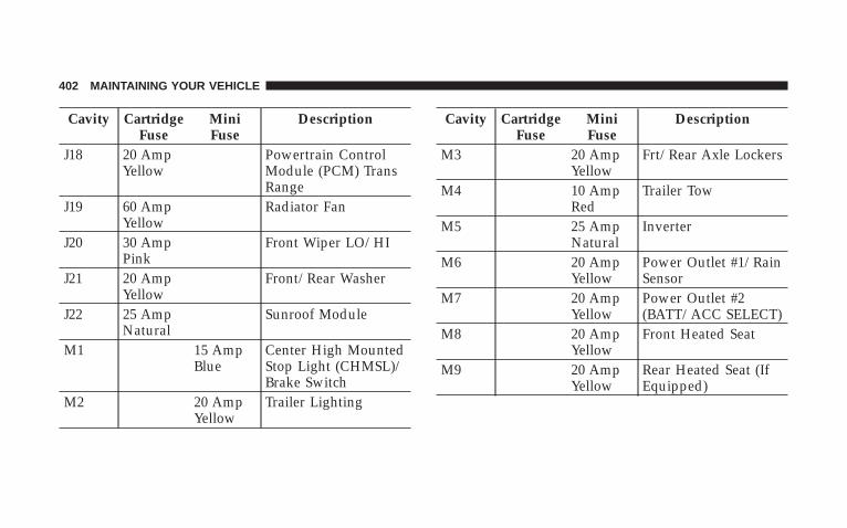
Cavity CartridgeFuse
MiniFuse
Description
J18 20 AmpYellow
Powertrain ControlModule (PCM) TransRange
J19 60 AmpYellow
Radiator Fan
J20 30 AmpPink
Front Wiper LO/HI
J21 20 AmpYellow
Front/Rear Washer
J22 25 AmpNatural
Sunroof Module
M1 15 AmpBlue
Center High MountedStop Light (CHMSL)/Brake Switch
M2 20 AmpYellow
Trailer Lighting
Cavity CartridgeFuse
MiniFuse
Description
M3 20 AmpYellow
Frt/Rear Axle Lockers
M4 10 AmpRed
Trailer Tow
M5 25 AmpNatural
Inverter
M6 20 AmpYellow
Power Outlet #1/RainSensor
M7 20 AmpYellow
Power Outlet #2(BATT/ACC SELECT)
M8 20 AmpYellow
Front Heated Seat
M9 20 AmpYellow
Rear Heated Seat (IfEquipped)
402 MAINTAINING YOUR VEHICLE
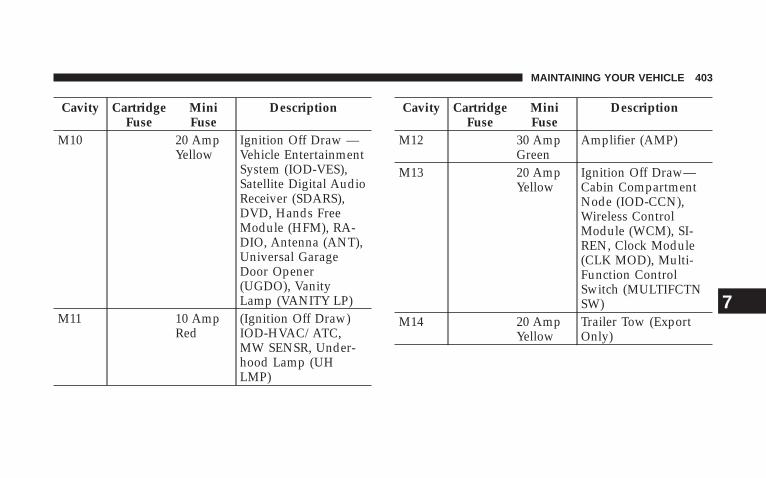
Cavity CartridgeFuse
MiniFuse
Description
M10 20 AmpYellow
Ignition Off Draw —Vehicle EntertainmentSystem (IOD-VES),Satellite Digital AudioReceiver (SDARS),DVD, Hands FreeModule (HFM), RA-DIO, Antenna (ANT),Universal GarageDoor Opener(UGDO), VanityLamp (VANITY LP)
M11 10 AmpRed
(Ignition Off Draw)IOD-HVAC/ATC,MW SENSR, Under-hood Lamp (UHLMP)
Cavity CartridgeFuse
MiniFuse
Description
M12 30 AmpGreen
Amplifier (AMP)
M13 20 AmpYellow
Ignition Off Draw—Cabin CompartmentNode (IOD-CCN),Wireless ControlModule (WCM), SI-REN, Clock Module(CLK MOD), Multi-Function ControlSwitch (MULTIFCTNSW)
M14 20 AmpYellow
Trailer Tow (ExportOnly)
MAINTAINING YOUR VEHICLE 403
7
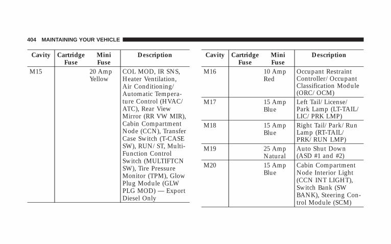
Cavity CartridgeFuse
MiniFuse
Description
M15 20 AmpYellow
COL MOD, IR SNS,Heater Ventilation,Air Conditioning/Automatic Tempera-ture Control (HVAC/ATC), Rear ViewMirror (RR VW MIR),Cabin CompartmentNode (CCN), TransferCase Switch (T-CASESW), RUN/ST, Multi-Function ControlSwitch (MULTIFTCNSW), Tire PressureMonitor (TPM), GlowPlug Module (GLWPLG MOD) — ExportDiesel Only
Cavity CartridgeFuse
MiniFuse
Description
M16 10 AmpRed
Occupant RestraintController/OccupantClassification Module(ORC/OCM)
M17 15 AmpBlue
Left Tail/License/Park Lamp (LT-TAIL/LIC/PRK LMP)
M18 15 AmpBlue
Right Tail/Park/RunLamp (RT-TAIL/PRK/RUN LMP)
M19 25 AmpNatural
Auto Shut Down(ASD #1 and #2)
M20 15 AmpBlue
Cabin CompartmentNode Interior Light(CCN INT LIGHT),Switch Bank (SWBANK), Steering Con-trol Module (SCM)
404 MAINTAINING YOUR VEHICLE
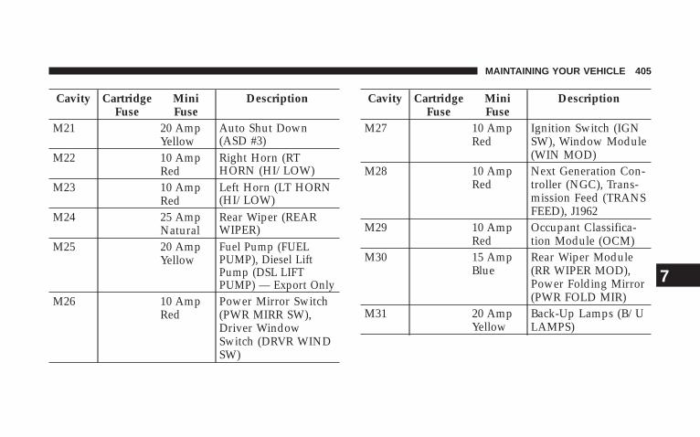
Cavity CartridgeFuse
MiniFuse
Description
M21 20 AmpYellow
Auto Shut Down(ASD #3)
M22 10 AmpRed
Right Horn (RTHORN (HI/LOW)
M23 10 AmpRed
Left Horn (LT HORN(HI/LOW)
M24 25 AmpNatural
Rear Wiper (REARWIPER)
M25 20 AmpYellow
Fuel Pump (FUELPUMP), Diesel LiftPump (DSL LIFTPUMP) — Export Only
M26 10 AmpRed
Power Mirror Switch(PWR MIRR SW),Driver WindowSwitch (DRVR WINDSW)
Cavity CartridgeFuse
MiniFuse
Description
M27 10 AmpRed
Ignition Switch (IGNSW), Window Module(WIN MOD)
M28 10 AmpRed
Next Generation Con-troller (NGC), Trans-mission Feed (TRANSFEED), J1962
M29 10 AmpRed
Occupant Classifica-tion Module (OCM)
M30 15 AmpBlue
Rear Wiper Module(RR WIPER MOD),Power Folding Mirror(PWR FOLD MIR)
M31 20 AmpYellow
Back-Up Lamps (B/ULAMPS)
MAINTAINING YOUR VEHICLE 405
7
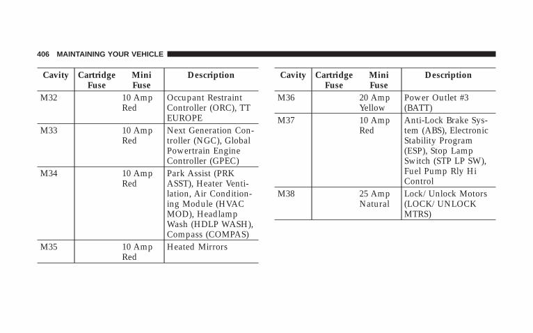
Cavity CartridgeFuse
MiniFuse
Description
M32 10 AmpRed
Occupant RestraintController (ORC), TTEUROPE
M33 10 AmpRed
Next Generation Con-troller (NGC), GlobalPowertrain EngineController (GPEC)
M34 10 AmpRed
Park Assist (PRKASST), Heater Venti-lation, Air Condition-ing Module (HVACMOD), HeadlampWash (HDLP WASH),Compass (COMPAS)
M35 10 AmpRed
Heated Mirrors
Cavity CartridgeFuse
MiniFuse
Description
M36 20 AmpYellow
Power Outlet #3(BATT)
M37 10 AmpRed
Anti-Lock Brake Sys-tem (ABS), ElectronicStability Program(ESP), Stop LampSwitch (STP LP SW),Fuel Pump Rly HiControl
M38 25 AmpNatural
Lock/Unlock Motors(LOCK/UNLOCKMTRS)
406 MAINTAINING YOUR VEHICLE
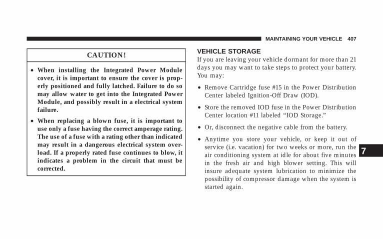
CAUTION!
• When installing the Integrated Power Modulecover, it is important to ensure the cover is prop-erly positioned and fully latched. Failure to do somay allow water to get into the Integrated PowerModule, and possibly result in a electrical systemfailure.
• When replacing a blown fuse, it is important touse only a fuse having the correct amperage rating.The use of a fuse with a rating other than indicatedmay result in a dangerous electrical system over-load. If a properly rated fuse continues to blow, itindicates a problem in the circuit that must becorrected.
VEHICLE STORAGEIf you are leaving your vehicle dormant for more than 21days you may want to take steps to protect your battery.You may:
• Remove Cartridge fuse #15 in the Power DistributionCenter labeled Ignition-Off Draw (IOD).
• Store the removed IOD fuse in the Power DistributionCenter location #11 labeled “IOD Storage.”
• Or, disconnect the negative cable from the battery.
• Anytime you store your vehicle, or keep it out ofservice (i.e. vacation) for two weeks or more, run theair conditioning system at idle for about five minutesin the fresh air and high blower setting. This willinsure adequate system lubrication to minimize thepossibility of compressor damage when the system isstarted again.
MAINTAINING YOUR VEHICLE 407
7
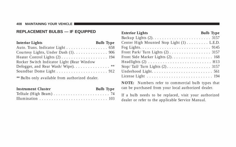
REPLACEMENT BULBS — IF EQUIPPED
Interior Lights Bulb TypeAuto. Trans. Indicator Light . . . . . . . . . . . . . . . . . 658Courtesy Lights, Under Dash (1) . . . . . . . . . . . . . . 906Heater Control Lights (2) . . . . . . . . . . . . . . . . . . . 194Rocker Switch Indicator Light (Rear WindowDefogger, and Rear Wash/Wipe). . . . . . . . . . . . . . . **Soundbar Dome Light . . . . . . . . . . . . . . . . . . . . . 912
** Bulbs only available from authorized dealer.
Instrument Cluster Bulb TypeTelltale (High Beam) . . . . . . . . . . . . . . . . . . . . . . . 74Illumination . . . . . . . . . . . . . . . . . . . . . . . . . . . . 103
Exterior Lights Bulb TypeBackup Lights (2). . . . . . . . . . . . . . . . . . . . . . . . 3157Center High Mounted Stop Light (1) . . . . . . . . . L.E.D.Fog Lights. . . . . . . . . . . . . . . . . . . . . . . . . . . . . 9145Front Park/Turn Lights (2) . . . . . . . . . . . . . . . . . 3157Front Side Marker Lights (2). . . . . . . . . . . . . . . . . 168Headlights (2) . . . . . . . . . . . . . . . . . . . . . . . . . . H13Stop/Tail/Turn Lights (2) . . . . . . . . . . . . . . . . . . 3157Underhood Light. . . . . . . . . . . . . . . . . . . . . . . . . 561License Light . . . . . . . . . . . . . . . . . . . . . . . . . . . 194
NOTE: Numbers refer to commercial bulb types thatcan be purchased from your local authorized dealer.
If a bulb needs to be replaced, visit your authorizeddealer or refer to the applicable Service Manual.
408 MAINTAINING YOUR VEHICLE
BULB REPLACEMENT
Head Light
1. Open hood and support using prop rod.
2. Remove the front grille. Turn the retainers along thetop 1/4 turn counter-clockwise and remove.
3. Pull the bottom of the grille away starting at one sideand working toward the other.
4. Turn both park and turn signal socket assemblies 1/4turn counter-clockwise and remove.
5. Remove the four screws holding the metal retainingring.
6. Remove the lamp from the collar.
7. Grasp the bulb and turn 1/4 turn counter-clockwise.
8. Pull the bulb from the housing.
9. Push connector locking tab to the unlock position.
10. Remove connector from bulb.
11. Push connector onto new bulb base, and push theconnector locking tab to the lock position.
CAUTION!
Do not touch the new bulb with your fingers. Oilcontamination will severely shorten bulb life. If thebulb comes in contact with any oily surface, clean thebulb with rubbing alcohol.
12. Reinstall bulb housing. Rotate the bulb 1/4 turnclockwise.
MAINTAINING YOUR VEHICLE 409
7
Front Park/Turn Signal
1. Remove the front grille. Turn the retainers along thetop 1/4 turn counter-clockwise and remove.
2. Pull the bottom of the grille away starting at one sideand working toward the other.
3. Turn the socket assembly 1/4 turn counter-clockwiseand remove from housing. Pull the bulb straight from thesocket to replace.
Front Side Marker
1. Reach under the front fender flare and locate the frontside marker socket.
2. Turn the socket assembly counter–clockwise 1/3 turnand remove it from the housing. Pull the bulb straightfrom the socket to replace.
Front Fog Light
1. Locate the front fog lamp in the front fascia, anddisconnect the electrical connector from underneath.
2. Turn the bulb 1/4 turn counter-clockwise.
CAUTION!
Do not touch the new bulb with your fingers. Oilcontamination will severely shorten bulb life. If thebulb comes in contact with any oily surface, clean thebulb with rubbing alcohol.
410 MAINTAINING YOUR VEHICLE
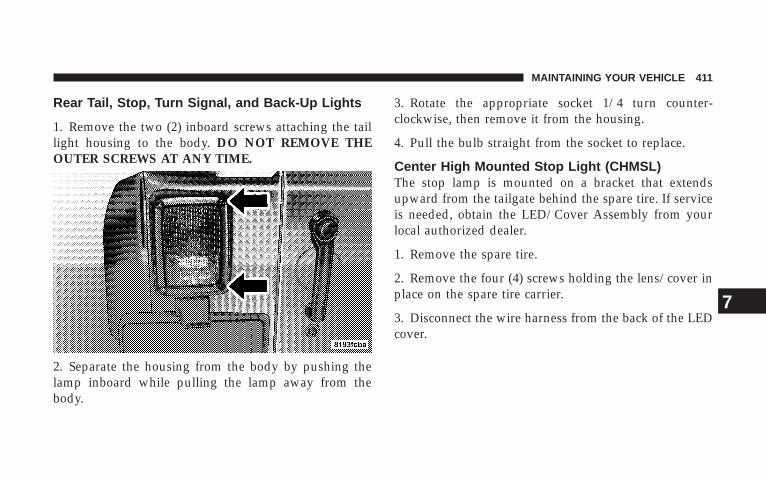
Rear Tail, Stop, Turn Signal, and Back-Up Lights
1. Remove the two (2) inboard screws attaching the taillight housing to the body. DO NOT REMOVE THEOUTER SCREWS AT ANY TIME.
2. Separate the housing from the body by pushing thelamp inboard while pulling the lamp away from thebody.
3. Rotate the appropriate socket 1/4 turn counter-clockwise, then remove it from the housing.
4. Pull the bulb straight from the socket to replace.
Center High Mounted Stop Light (CHMSL)The stop lamp is mounted on a bracket that extendsupward from the tailgate behind the spare tire. If serviceis needed, obtain the LED/Cover Assembly from yourlocal authorized dealer.
1. Remove the spare tire.
2. Remove the four (4) screws holding the lens/cover inplace on the spare tire carrier.
3. Disconnect the wire harness from the back of the LEDcover.
MAINTAINING YOUR VEHICLE 411
7
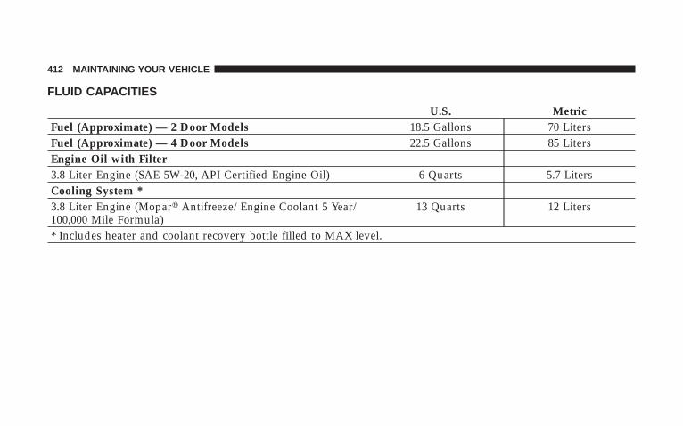
FLUID CAPACITIES
U.S. MetricFuel (Approximate) — 2 Door Models 18.5 Gallons 70 LitersFuel (Approximate) — 4 Door Models 22.5 Gallons 85 LitersEngine Oil with Filter3.8 Liter Engine (SAE 5W-20, API Certified Engine Oil) 6 Quarts 5.7 LitersCooling System *3.8 Liter Engine (Mopar� Antifreeze/Engine Coolant 5 Year/100,000 Mile Formula)
13 Quarts 12 Liters
* Includes heater and coolant recovery bottle filled to MAX level.
412 MAINTAINING YOUR VEHICLE
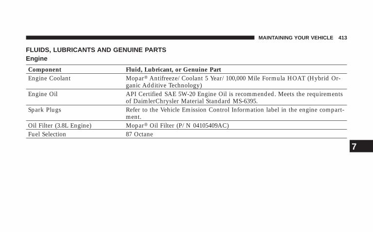
FLUIDS, LUBRICANTS AND GENUINE PARTSEngine
Component Fluid, Lubricant, or Genuine PartEngine Coolant Mopar� Antifreeze/Coolant 5 Year/100,000 Mile Formula HOAT (Hybrid Or-
ganic Additive Technology)Engine Oil API Certified SAE 5W-20 Engine Oil is recommended. Meets the requirements
of DaimlerChrysler Material Standard MS-6395.Spark Plugs Refer to the Vehicle Emission Control Information label in the engine compart-
ment.Oil Filter (3.8L Engine) Mopar� Oil Filter (P/N 04105409AC)Fuel Selection 87 Octane
MAINTAINING YOUR VEHICLE 413
7
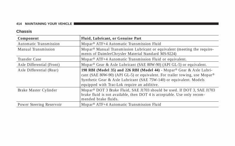
Chassis
Component Fluid, Lubricant, or Genuine PartAutomatic Transmission Mopar� ATF+4 Automatic Transmission FluidManual Transmission Mopar� Manual Transmission Lubricant or equivalent (meeting the require-
ments of DaimlerChrysler Material Standard MS-9224)Transfer Case Mopar� ATF+4 Automatic Transmission Fluid or equivalent.Axle Differential (Front) Mopar� Gear & Axle Lubricant (SAE 80W-90) (API GL-5) or equivalent.Axle Differential (Rear) 198 RBI (Model 35) and 226 RBI (Model 44) - Mopar� Gear & Axle Lubri-
cant (SAE 80W-90) (API GL-5) or equivalent. For trailer towing, use Mopar�Synthetic Gear & Axle Lubricant (SAE 75W-140) or equivalent. Modelsequipped with Trac-Lok require an additive.
Brake Master Cylinder Mopar� DOT 3 Brake Fluid, SAE J1703 should be used. If DOT 3, SAE J1703brake fluid is not available, then DOT 4 is acceptable. Use only recom-mended brake fluids.
Power Steering Reservoir Mopar� ATF+4 Automatic Transmission Fluid
414 MAINTAINING YOUR VEHICLE
MAINTENANCE SCHEDULES
CONTENTS
� Emission Control System Maintenance . . . . . . . . 416
� Maintenance Schedules . . . . . . . . . . . . . . . . . . . 416
▫ Schedule “B” . . . . . . . . . . . . . . . . . . . . . . . . 419
▫ Schedule “A” . . . . . . . . . . . . . . . . . . . . . . . . 432
8
MAINTENANCE
SCHEDULES
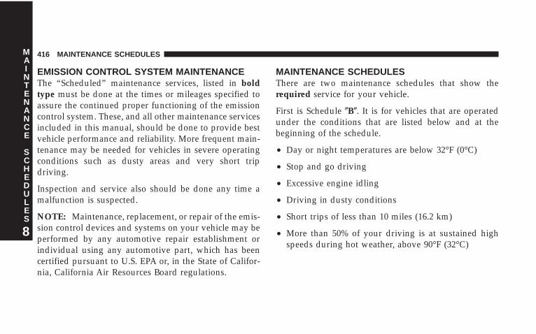
EMISSION CONTROL SYSTEM MAINTENANCEThe “Scheduled” maintenance services, listed in boldtype must be done at the times or mileages specified toassure the continued proper functioning of the emissioncontrol system. These, and all other maintenance servicesincluded in this manual, should be done to provide bestvehicle performance and reliability. More frequent main-tenance may be needed for vehicles in severe operatingconditions such as dusty areas and very short tripdriving.
Inspection and service also should be done any time amalfunction is suspected.
NOTE: Maintenance, replacement, or repair of the emis-sion control devices and systems on your vehicle may beperformed by any automotive repair establishment orindividual using any automotive part, which has beencertified pursuant to U.S. EPA or, in the State of Califor-nia, California Air Resources Board regulations.
MAINTENANCE SCHEDULESThere are two maintenance schedules that show therequired service for your vehicle.
First is Schedule �B�. It is for vehicles that are operatedunder the conditions that are listed below and at thebeginning of the schedule.
• Day or night temperatures are below 32°F (0°C)
• Stop and go driving
• Excessive engine idling
• Driving in dusty conditions
• Short trips of less than 10 miles (16.2 km)
• More than 50% of your driving is at sustained highspeeds during hot weather, above 90°F (32°C)
416 MAINTENANCE SCHEDULES
8
MAINTENANCE
SCHEDULES
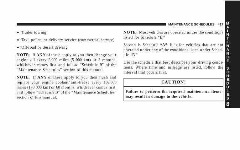
• Trailer towing
• Taxi, police, or delivery service (commercial service)
• Off-road or desert driving
NOTE: If ANY of these apply to you then change yourengine oil every 3,000 miles (5 000 km) or 3 months,whichever comes first and follow “Schedule B” of the“Maintenance Schedules” section of this manual.
NOTE: If ANY of these apply to you then flush andreplace your engine coolant/anti-freeze every 102,000miles (170 000 km) or 60 months, whichever comes first,and follow “Schedule B” of the “Maintenance Schedules”section of this manual.
NOTE: Most vehicles are operated under the conditionslisted for Schedule “B.”
Second is Schedule “A”. It is for vehicles that are notoperated under any of the conditions listed under Sched-ule “B.”
Use the schedule that best describes your driving condi-tions. Where time and mileage are listed, follow theinterval that occurs first.
CAUTION!
Failure to perform the required maintenance itemsmay result in damage to the vehicle.
MAINTENANCE SCHEDULES 417
8
MAINTENANCE
SCHEDULES
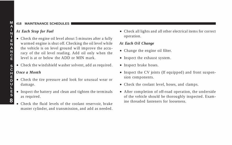
At Each Stop for Fuel
• Check the engine oil level about 5 minutes after a fullywarmed engine is shut off. Checking the oil level whilethe vehicle is on level ground will improve the accu-racy of the oil level reading. Add oil only when thelevel is at or below the ADD or MIN mark.
• Check the windshield washer solvent, add as required.
Once a Month
• Check the tire pressure and look for unusual wear ordamage.
• Inspect the battery and clean and tighten the terminalsas required.
• Check the fluid levels of the coolant reservoir, brakemaster cylinder, and transmission, and add as needed.
• Check all lights and all other electrical items for correctoperation.
At Each Oil Change
• Change the engine oil filter.
• Inspect the exhaust system.
• Inspect brake hoses.
• Inspect the CV joints (If equipped) and front suspen-sion components.
• Check the coolant level, hoses, and clamps.
• After completion of off-road operation, the undersideof the vehicle should be thoroughly inspected. Exam-ine threaded fasteners for looseness.
418 MAINTENANCE SCHEDULES
8
MAINTENANCE
SCHEDULES
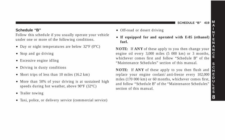
Schedule “B”Follow this schedule if you usually operate your vehicleunder one or more of the following conditions.
• Day or night temperatures are below 32°F (0°C)
• Stop and go driving
• Excessive engine idling
• Driving in dusty conditions
• Short trips of less than 10 miles (16.2 km)
• More than 50% of your driving is at sustained highspeeds during hot weather, above 90°F (32°C)
• Trailer towing
• Taxi, police, or delivery service (commercial service)
• Off-road or desert driving
• If equipped for and operated with E-85 (ethanol)fuel.
NOTE: If ANY of these apply to you then change yourengine oil every 3,000 miles (5 000 km) or 3 months,whichever comes first and follow “Schedule B” of the“Maintenance Schedules” section of this manual.
NOTE: If ANY of these apply to you then flush andreplace your engine coolant/anti-freeze every 102,000miles (170 000 km) or 60 months, whichever comes first,and follow “Schedule B” of the “Maintenance Schedules”section of this manual.
SCHEDULE “B” 419
8
MAINTENANCE
SCHEDULES
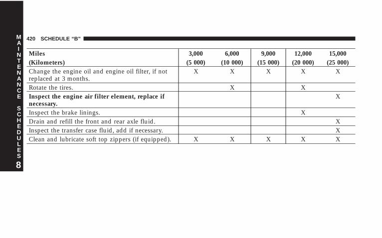
Miles 3,000 6,000 9,000 12,000 15,000(Kilometers) (5 000) (10 000) (15 000) (20 000) (25 000)Change the engine oil and engine oil filter, if notreplaced at 3 months.
X X X X X
Rotate the tires. X XInspect the engine air filter element, replace ifnecessary.
X
Inspect the brake linings. XDrain and refill the front and rear axle fluid. XInspect the transfer case fluid, add if necessary. XClean and lubricate soft top zippers (if equipped). X X X X X
420 SCHEDULE “B”
8
MAINTENANCE
SCHEDULES
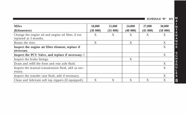
Miles 18,000 21,000 24,000 27,000 30,000(Kilometers) (30 000) (35 000) (40 000) (45 000) (50 000)Change the engine oil and engine oil filter, if notreplaced at 3 months.
X X X X X
Rotate the tires. X X XInspect the engine air filter element, replace ifnecessary.
X
Inspect the PCV Valve, and replace if necessary.� XInspect the brake linings. XDrain and refill the front and rear axle fluid. XInspect the manual transmission fluid, add as nec-essary.
X
Inspect the transfer case fluid, add if necessary. XClean and lubricate soft top zippers (if equipped). X X X X X
SCHEDULE “B” 421
8
MAINTENANCE
SCHEDULES
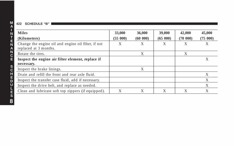
Miles 33,000 36,000 39,000 42,000 45,000(Kilometers) (55 000) (60 000) (65 000) (70 000) (75 000)Change the engine oil and engine oil filter, if notreplaced at 3 months.
X X X X X
Rotate the tires. X XInspect the engine air filter element, replace ifnecessary.
X
Inspect the brake linings. XDrain and refill the front and rear axle fluid. XInspect the transfer case fluid, add if necessary. XInspect the drive belt, and replace as needed. XClean and lubricate soft top zippers (if equipped). X X X X X
422 SCHEDULE “B”
8
MAINTENANCE
SCHEDULES
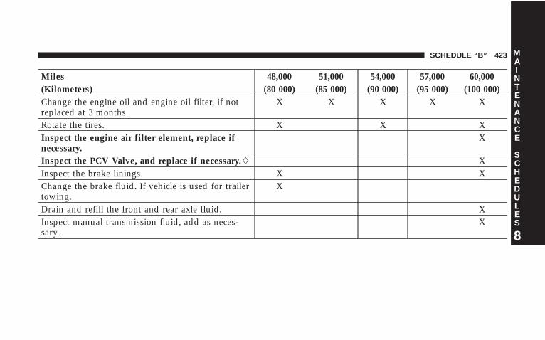
Miles 48,000 51,000 54,000 57,000 60,000(Kilometers) (80 000) (85 000) (90 000) (95 000) (100 000)Change the engine oil and engine oil filter, if notreplaced at 3 months.
X X X X X
Rotate the tires. X X XInspect the engine air filter element, replace ifnecessary.
X
Inspect the PCV Valve, and replace if necessary.� XInspect the brake linings. X XChange the brake fluid. If vehicle is used for trailertowing.
X
Drain and refill the front and rear axle fluid. XInspect manual transmission fluid, add as neces-sary.
X
SCHEDULE “B” 423
8
MAINTENANCE
SCHEDULES
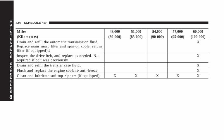
Miles 48,000 51,000 54,000 57,000 60,000(Kilometers) (80 000) (85 000) (90 000) (95 000) (100 000)Drain and refill the automatic transmission fluid.Replace main sump filter and spin-on cooler returnfilter (if equipped).‡
X
Inspect the drive belt, and replace as needed. Notrequired if belt was previously.
X
Drain and refill the transfer case fluid. XFlush and replace the engine coolant/anti-freeze. XClean and lubricate soft top zippers (if equipped). X X X X X
424 SCHEDULE “B”
8
MAINTENANCE
SCHEDULES

Miles 63,000 66,000 69,000 72,000 75,000(Kilometers) (105 000) (110 000) (115 000) (120 000) (125 000)Change the engine oil and engine oil filter, if notreplaced at 3 months.
X X X X X
Rotate the tires. X XInspect the engine air filter element, replace ifnecessary.
X
Inspect the brake linings. XInspect the transfer case fluid, add if necessary. XDrain and refill the front and rear axle fluid. XInspect the drive belt, and replace as needed. Notrequired if belt was previously replaced.
X
Clean and lubricate soft top zippers (if equipped). X X X X X
SCHEDULE “B” 425
8
MAINTENANCE
SCHEDULES
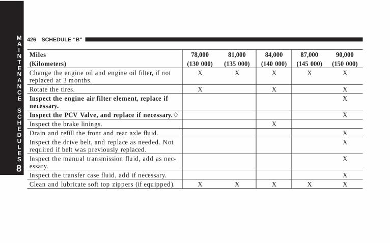
Miles 78,000 81,000 84,000 87,000 90,000(Kilometers) (130 000) (135 000) (140 000) (145 000) (150 000)Change the engine oil and engine oil filter, if notreplaced at 3 months.
X X X X X
Rotate the tires. X X XInspect the engine air filter element, replace ifnecessary.
X
Inspect the PCV Valve, and replace if necessary.� XInspect the brake linings. XDrain and refill the front and rear axle fluid. XInspect the drive belt, and replace as needed. Notrequired if belt was previously replaced.
X
Inspect the manual transmission fluid, add as nec-essary.
X
Inspect the transfer case fluid, add if necessary. XClean and lubricate soft top zippers (if equipped). X X X X X
426 SCHEDULE “B”
8
MAINTENANCE
SCHEDULES
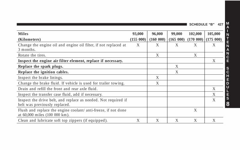
Miles 93,000 96,000 99,000 102,000 105,000(Kilometers) (155 000) (160 000) (165 000) (170 000) (175 000)Change the engine oil and engine oil filter, if not replaced at3 months.
X X X X X
Rotate the tires. X XInspect the engine air filter element, replace if necessary. XReplace the spark plugs. XReplace the ignition cables. XInspect the brake linings. XChange the brake fluid. If vehicle is used for trailer towing. XDrain and refill the front and rear axle fluid. XInspect the transfer case fluid, add if necessary. XInspect the drive belt, and replace as needed. Not required ifbelt was previously replaced.
X
Flush and replace the engine coolant/anti-freeze, if not doneat 60,000 miles (100 000 km).
X
Clean and lubricate soft top zippers (if equipped). X X X X X
SCHEDULE “B” 427
8
MAINTENANCE
SCHEDULES
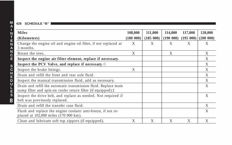
Miles 108,000 111,000 114,000 117,000 120,000(Kilometers) (180 000) (185 000) (190 000) (195 000) (200 000)Change the engine oil and engine oil filter, if not replaced at3 months.
X X X X X
Rotate the tires. X X XInspect the engine air filter element, replace if necessary. XInspect the PCV Valve, and replace if necessary.� XInspect the brake linings. X XDrain and refill the front and rear axle fluid. XInspect the manual transmission fluid, add as necessary. XDrain and refill the automatic transmission fluid. Replace mainsump filter and spin-on cooler return filter (if equipped).‡
X
Inspect the drive belt, and replace as needed. Not required ifbelt was previously replaced.
X
Drain and refill the transfer case fluid. XFlush and replace the engine coolant/anti-freeze, if not re-placed at 102,000 miles (170 000 km).
X
Clean and lubricate soft top zippers (if equipped). X X X X X
428 SCHEDULE “B”
8
MAINTENANCE
SCHEDULES

Miles 123,000 126,000 129,000 132,000 135,000(Kilometers) (205 000) (210 000) (215 000) (220 000) (225 000)Change the engine oil and engine oil filter, if notreplaced at 3 months.
X X X X X
Rotate the tires. X XInspect the engine air filter element, replace ifnecessary.
X
Inspect the brake linings. XDrain and refill the front and rear axle fluid. XInspect the transfer case fluid, add if necessary. XInspect the drive belt, and replace as needed. Notrequired if belt was previously replaced.
X
Clean and lubricate soft top zippers (if equipped). X X X X X
SCHEDULE “B” 429
8
MAINTENANCE
SCHEDULES

Miles 138,000 141,000 144,000 147,000 150,000(Kilometers) (230 000) (235 000) (240 000) (245 000) (250 000)Change the engine oil and engine oil filter, if not replaced at3 months.
X X X X X
Rotate the tires. X XInspect the engine air filter element, replace if necessary. XInspect the PCV Valve, and replace if necessary.� XInspect the brake linings. XChange the brake fluid. If vehicle is used for trailer towing. XDrain and refill the front and rear axle fluid. XInspect the manual transmission fluid, add as necessary. XInspect the transfer case fluid, add if necessary. XInspect the drive belt, and replace as needed. Not required ifbelt was previously replaced.
X
Flush and replace the engine coolant/anti-freeze, if not doneat 120,000 miles (200 000 km).
X
Clean and lubricate soft top zippers (if equipped). X X X X X
430 SCHEDULE “B”
8
MAINTENANCE
SCHEDULES
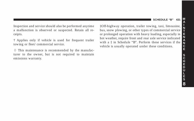
Inspection and service should also be performed anytimea malfunction is observed or suspected. Retain all re-ceipts.
† Applies only if vehicle is used for frequent trailertowing or fleet/commercial service.
� This maintenance is recommended by the manufac-turer to the owner, but is not required to maintainemissions warranty.
‡Off-highway operation, trailer towing, taxi, limousine,bus, snow plowing, or other types of commercial serviceor prolonged operation with heavy loading, especially inhot weather, require front and rear axle service indicatedwith a ‡ in Schedule “B”. Perform these services if thevehicle is usually operated under these conditions.
SCHEDULE “B” 431
8
MAINTENANCE
SCHEDULES
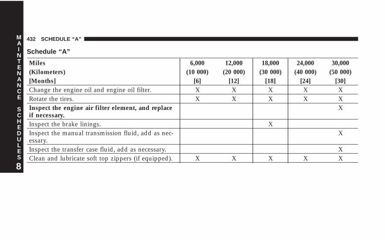
Schedule “A”
Miles 6,000 12,000 18,000 24,000 30,000(Kilometers) (10 000) (20 000) (30 000) (40 000) (50 000)[Months] [6] [12] [18] [24] [30]Change the engine oil and engine oil filter. X X X X XRotate the tires. X X X X XInspect the engine air filter element, and replaceif necessary.
X
Inspect the brake linings. XInspect the manual transmission fluid, add as nec-essary.
X
Inspect the transfer case fluid, add as necessary. XClean and lubricate soft top zippers (if equipped). X X X X X
432 SCHEDULE “A”
8
MAINTENANCE
SCHEDULES

Miles 36,000 42,000 48,000 54, 000(Kilometers) (60 000) (70 000) (80 000) (90 000)[Months] [36] [42] [48] [54]Change the engine oil and engine oil filter. X X X XRotate the tires. X X X XInspect the brake linings. X XClean and lubricate soft top zippers (if equipped). X X X X
SCHEDULE “A” 433
8
MAINTENANCE
SCHEDULES
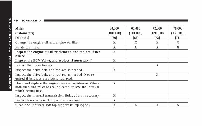
Miles 60,000 66,000 72,000 78,000(Kilometers) (100 000) (110 000) (120 000) (130 000)[Months] [60] [66] [72] [78]Change the engine oil and engine oil filter. X X X XRotate the tires. X X X XInspect the engine air filter element, and replace if nec-essary.
X
Inspect the PCV Valve, and replace if necessary.� XInspect the brake linings. XInspect the drive belt, and replace as needed. XInspect the drive belt, and replace as needed. Not re-quired if belt was previously replaced.
X
Flush and replace the engine coolant/anti-freeze. Whereboth time and mileage are indicated, follow the intervalwhich occurs first.
X
Inspect the manual transmission fluid, add as necessary. XInspect transfer case fluid, add as necessary. XClean and lubricate soft top zippers (if equipped). X X X X
434 SCHEDULE “A”
8
MAINTENANCE
SCHEDULES
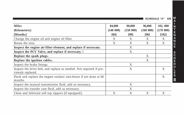
Miles 84,000 90,000 96,000 102, 000(Kilometers) (140 000) (150 000) (160 000) (170 000)[Months] [84] [90] [96] [102]Change the engine oil and engine oil filter. X X X XRotate the tires. X X X XInspect the engine air filter element, and replace if necessary. XInspect the PCV Valve, and replace if necessary.� XReplace the spark plugs. XReplace the ignition cables. XInspect the brake linings. XInspect the drive belt, and replace as needed. Not required if pre-viously replaced.
X X
Flush and replace the engine coolant/anti-freeze if not done at 60months.
X
Inspect the manual transmission fluid, add as necessary. XInspect the transfer case fluid, add as necessary. XClean and lubricate soft top zippers (if equipped). X X X X
SCHEDULE “A” 435
8
MAINTENANCE
SCHEDULES
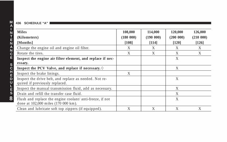
Miles 108,000 114,000 120,000 126,000(Kilometers) (180 000) (190 000) (200 000) (210 000)[Months] [108] [114] [120] [126]Change the engine oil and engine oil filter. X X X XRotate the tires. X X X XInspect the engine air filter element, and replace if nec-essary.
X
Inspect the PCV Valve, and replace if necessary.� XInspect the brake linings. XInspect the drive belt, and replace as needed. Not re-quired if previously replaced.
X
Inspect the manual transmission fluid, add as necessary. XDrain and refill the transfer case fluid. XFlush and replace the engine coolant/anti-freeze, if notdone at 102,000 miles (170 000 km).
X
Clean and lubricate soft top zippers (if equipped). X X X X
436 SCHEDULE “A”
8
MAINTENANCE
SCHEDULES
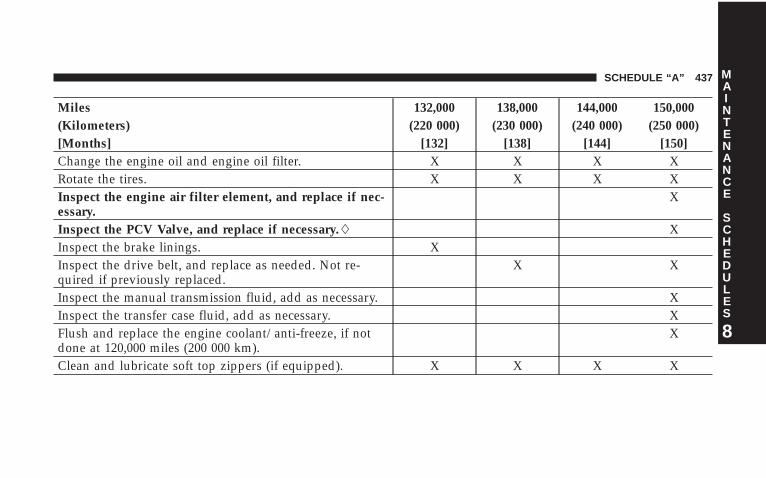
Miles 132,000 138,000 144,000 150,000(Kilometers) (220 000) (230 000) (240 000) (250 000)[Months] [132] [138] [144] [150]Change the engine oil and engine oil filter. X X X XRotate the tires. X X X XInspect the engine air filter element, and replace if nec-essary.
X
Inspect the PCV Valve, and replace if necessary.� XInspect the brake linings. XInspect the drive belt, and replace as needed. Not re-quired if previously replaced.
X X
Inspect the manual transmission fluid, add as necessary. XInspect the transfer case fluid, add as necessary. XFlush and replace the engine coolant/anti-freeze, if notdone at 120,000 miles (200 000 km).
X
Clean and lubricate soft top zippers (if equipped). X X X X
SCHEDULE “A” 437
8
MAINTENANCE
SCHEDULES
Inspection and service should also be performed anytimea malfunction is observed or suspected. Retain all re-ceipts.
� This maintenance is recommended by the manufac-turer to the owner, but is not required to maintainemissions warranty.
438 SCHEDULE “A”
8
MAINTENANCE
SCHEDULES
IF YOU NEED CONSUMER ASSISTANCE
CONTENTS
� Suggestions For Obtaining Service For YourVehicle . . . . . . . . . . . . . . . . . . . . . . . . . . . . . . 440
▫ Prepare For The Appointment . . . . . . . . . . . . 440
▫ Prepare A List . . . . . . . . . . . . . . . . . . . . . . . . 440
▫ Be Reasonable With Requests . . . . . . . . . . . . . 440
� If You Need Assistance . . . . . . . . . . . . . . . . . . . 440
� Warranty Information (U.S. Vehicles Only) . . . . . 443
� Mopar� Parts . . . . . . . . . . . . . . . . . . . . . . . . . 443
� Reporting Safety Defects . . . . . . . . . . . . . . . . . . 443
▫ In Canada . . . . . . . . . . . . . . . . . . . . . . . . . . 444
� Publication Order Forms . . . . . . . . . . . . . . . . . . 444
� Department Of Transportation Uniform TireQuality Grades . . . . . . . . . . . . . . . . . . . . . . . . 446
▫ Treadwear . . . . . . . . . . . . . . . . . . . . . . . . . . 446
▫ Traction Grades . . . . . . . . . . . . . . . . . . . . . . 446
▫ Temperature Grades . . . . . . . . . . . . . . . . . . . 447 9
SUGGESTIONS FOR OBTAINING SERVICE FORYOUR VEHICLE
Prepare For The AppointmentIf you’re having warranty work done, be sure to have theright papers with you. Take your warranty folder. Allwork to be performed may not be covered by thewarranty, discuss additional charges with the servicemanager. Keep a maintenance log of your vehicle’sservice history. This can often provide a clue to thecurrent problem.
Prepare A ListMake a written list of your vehicle’s problems or thespecific work you want done. If you’ve had an accident,or work done that is not on your maintenance log, let theservice advisor know.
Be Reasonable With RequestsIf you list a number of items, and you must have yourvehicle by the end of the day, discuss the situation withthe service advisor and list the items in order of priority.At many dealers, you may obtain a rental vehicle at aminimal daily charge. If you need a rental, it is advisableto make these arrangements when you call for an ap-pointment.
IF YOU NEED ASSISTANCEThe manufacturer and its dealers are vitally interested inyour satisfaction. We want you to be happy with ourproducts and services.
Warranty service must be done by an authorizedChrysler, Dodge, or Jeep dealer. We strongly recommendthat you take your vehicle to your selling dealer. Theyknow you and your vehicle best, and are most concernedthat you get prompt and high quality service. Themanufacturer’s dealers have the facilities, factory-trained
440 IF YOU NEED CONSUMER ASSISTANCE
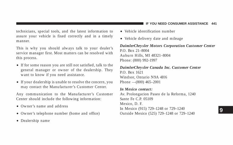
technicians, special tools, and the latest information toassure your vehicle is fixed correctly and in a timelymanner.
This is why you should always talk to your dealer’sservice manager first. Most matters can be resolved withthis process.
• If for some reason you are still not satisfied, talk to thegeneral manager or owner of the dealership. Theywant to know if you need assistance.
• If your dealership is unable to resolve the concern, youmay contact the Manufacturer’s Customer Center.
Any communication to the Manufacturer’s CustomerCenter should include the following information:
• Owner’s name and address
• Owner’s telephone number (home and office)
• Dealership name
• Vehicle identification number
• Vehicle delivery date and mileage
DaimlerChrysler Motors Corporation Customer CenterP.O. Box 21–8004Auburn Hills, MI 48321–8004Phone: (800) 992-1997
DaimlerChrysler Canada Inc. Customer CenterP.O. Box 1621Windsor, Ontario N9A 4H6Phone —(800) 465–2001
In Mexico contact:Av. Prolongacion Paseo de la Reforma, 1240Sante Fe C.P. 05109Mexico, D. F.In Mexico (915) 729–1248 or 729–1240Outside Mexico (525) 729–1248 or 729–1240
IF YOU NEED CONSUMER ASSISTANCE 441
9
Customer Assistance For The Hearing Or SpeechImpaired (TDD/TTY)To assist customers who have hearing difficulties, themanufacturer has installed special TDD (Telecommuni-cation Devices for the Deaf) equipment at its CustomerCenter. Any hearing or speech impaired customer whohas access to a TDD or a conventional teletypewriter(TTY) in the United States can communicate with themanufacturer by dialing 1–800–380–CHRY.
Service ContractYou may have purchased a service contract for yourvehicle to help protect you from the high cost of unex-pected repairs after your manufacturer’s new vehiclelimited warranty expires. The manufacturer stands be-hind only the manufacturer’s Service Contracts. If youpurchased a manufacturer’s Service Contract, you willreceive Plan Provisions and an Owner Identification Cardin the mail within three weeks of your vehicle deliverydate. If you have any questions about your service
contract, call the manufacturer’s Service Contract Na-tional Customer Hotline at 1-800-521-9922.
The manufacturer will not stand behind any servicecontract that is not the manufacturer’s Service Contract. Itis not responsible for any service contract other than themanufacturer’s Service Contract. If you purchased aservice contract that is not a manufacturer’s ServiceContract, and you require service after your manufactur-er’s new vehicle limited warranty expires, please refer toyour contract documents, and contact the person listed inthose documents.
We appreciate that you have made a major investmentwhen you purchased your new vehicle. Your dealer hasalso made a major investment in facilities, tools, andtraining to assure that you are absolutely delighted withyour ownership experience. You’ll be pleased with theirsincere efforts to resolve any warranty issues or relatedconcerns.
442 IF YOU NEED CONSUMER ASSISTANCE
WARNING!
Engine exhaust, some of its constituents, and certainvehicle components contain or emit chemicalsknown to the State of California to cause cancer andbirth defects or other reproductive harm. In addition,certain fluids contained in vehicles and certain prod-ucts of component wear contain or emit chemicalsknown to the State of California to cause cancer andbirth defects or other reproductive harm.
WARRANTY INFORMATION (U.S. Vehicles Only)See the Warranty Information Booklet for the terms andprovisions of DaimlerChrysler’s warranties applicable tothis vehicle.
MOPAR� PARTSMopar� fluids, lubricants, parts, and accessories areavailable from your dealer. They will help you keep yourvehicle operating at its best.
REPORTING SAFETY DEFECTSIn the 50 United States and Washington D.C.: If youbelieve that your vehicle has a defect, which could causea crash or cause injury or death, you should immediatelyinform the National Highway Traffic Safety Administra-tion (NHTSA) in addition to notifying the manufacturer.
If NHTSA receives similar complaints, it may open aninvestigation, and if it finds that a safety defect exists ina group of vehicles, it may order a recall and remedycampaign. However, NHTSA cannot become involved inindividual problems between you, your dealer, and themanufacturer.
IF YOU NEED CONSUMER ASSISTANCE 443
9
To contact NHTSA, you may either call the Auto SafetyHotline toll free at 1–888–327–4236 (TTY: 1–800–424–9153), or go to http://www.safercar.gov; or write to:Administrator, NHTSA, 400 Seventh Street, SW., Wash-ington, DC 20590. You can also obtain other informationabout motor vehicle safety from http://www.safercar.gov.
http://www.NHTSA.gov.
In Canada:If you believe that your vehicle has a safety defect, youshould contact the Customer Service Department imme-diately. Canadian customers who wish to report a safetydefect to the Canadian government should write toTransport Canada, Motor Vehicle Defect Investigationsand Recalls, 2780 Sheffield Road, Ottawa, Ontario K1B3V9.
PUBLICATION ORDER FORMSTo order the following manuals, you may use either thewebsite or the phone numbers listed below. Visa, Mas-tercard, American Express, and Discover orders are ac-cepted. If you prefer mailing your payment, please callfor an order form.
NOTE: A street address is required when orderingmanuals. (No P.O. Boxes).
• Service Manuals.
These comprehensive service manuals provide theinformation that students and professional techniciansneed in diagnosing/troubleshooting, problem solving,maintaining, servicing, and repairing DaimlerChryslerCorporation vehicles. A complete working knowledgeof the vehicle, system, and/or components is writtenin straightforward language with illustrations, dia-grams, and charts.
444 IF YOU NEED CONSUMER ASSISTANCE

• Diagnostic Procedure Manuals.
Filled with diagrams, charts and detailed illustrations,these practical manuals make it easy for students andtechnicians to find and fix problems on computer-controlled vehicle systems and features. They showexactly how to find and correct problems the first time,using step-by-step troubleshooting and driveabilityprocedures, proven diagnostic tests and a complete listof all tools and equipment.
• Owner’s Manuals.
These manuals have been prepared with the assistanceof service and engineering specialists to acquaint youwith specific Chrysler group vehicles. Included arestarting, operating, emergency and maintenance pro-cedures as well as specifications, capabilities andsafety tips.
Call Toll Free at:
• 1–800–890–4038 (U.S.)
• 1–800–387–1143 (Canada)
Or
Visit us on the World Wide Web at:
• www.techauthority.daimlerchrysler.com
• www.daimlerchrysler.ca/manuals
IF YOU NEED CONSUMER ASSISTANCE 445
9
DEPARTMENT OF TRANSPORTATION UNIFORMTIRE QUALITY GRADESThe following describes the tire grading categories estab-lished by the National highway Traffic Safety Adminis-tration. The specific grade rating assigned by the tire’smanufacturer in each category is shown on the sidewallof the tires on your car.
All Passenger Car Tires Must Conform to Federal SafetyRequirements in Addition to These Grades.
TreadwearThe treadwear grade is a comparative rating based on thewear rate of the tire when tested under controlled con-ditions on a specified government test course. For ex-ample, a tire graded 150 would wear one and a half (11/2) times as well on the government course as a tiregraded 100. The relative performance of tires dependsupon the actual conditions of their use, however, and
may depart significantly from the norm due to variationsin driving habits, service practices and differences in roadcharacteristics and climate.
Traction GradesThe traction grades, from highest to lowest, are AA, A, B,and C. Those grades represent the tire’s ability to stop onwet pavement as measured under controlled conditionson specified government test surfaces of asphalt andconcrete. A tire marked C may have poor traction perfor-mance.
WARNING!
The traction grade assigned to this tire is based onstraight-ahead braking traction tests, and does notinclude acceleration, cornering, hydroplaning, orpeak traction characteristics.
446 IF YOU NEED CONSUMER ASSISTANCE
Temperature GradesThe temperature grades are A (the highest), B, and C,representing the tire’s resistance to the generation of heatand its ability to dissipate heat when tested undercontrolled conditions on a specified indoor laboratorytest wheel. Sustained high temperature can cause thematerial of the tire to degenerate and reduce tire life, andexcessive temperature can lead to sudden tire failure. Thegrade C corresponds to a level of performance which allpassenger car tires must meet under the Federal MotorVehicle Safety Standard No. 109. Grades B and A repre-sent higher levels of performance on the laboratory testwheel than the minimum required by law.
WARNING!
The temperature grade for this tire is established fora tire that is properly inflated and not overloaded.Excessive speed, under inflation, or excessive load-ing, either separately or in combination, can causeheat buildup and possible tire failure.
IF YOU NEED CONSUMER ASSISTANCE 447
9


INDEX
10

ABS (Anti-Lock Brake System) . . . . . . . . . . . . 204,296Adding Fuel . . . . . . . . . . . . . . . . . . . . . . . . . . . 325Adding Washer Fluid . . . . . . . . . . . . . . . . . . . . . 194Air Cleaner, Engine (Engine Air Cleaner Filter) . . . 375Air Conditioner Maintenance . . . . . . . . . . . . . . . 376Air Conditioning . . . . . . . . . . . . . . . . . . . . . 254,258Air Conditioning Controls . . . . . . . . . . . . . . . . . 258Air Conditioning, Operating Tips . . . . . . . . . . . . 258Air Conditioning Refrigerant . . . . . . . . . . . . . . . 377Air Conditioning System . . . . . . . . . . . . . . . . . . 258Air Filter . . . . . . . . . . . . . . . . . . . . . . . . . . . . . . 375Air Pressure, Tires . . . . . . . . . . . . . . . . . . . . . . . 309Airbag . . . . . . . . . . . . . . . . . . . . . . . . . . . . . . . . 47Airbag Deployment . . . . . . . . . . . . . . . . . . . . . . . 60Airbag Light . . . . . . . . . . . . . . . . . . . . . . . . . 62,204Airbag Maintenance . . . . . . . . . . . . . . . . . . . . . . . 61Airbag, Side . . . . . . . . . . . . . . . . . . . . . . . . . . . . 58Alarm (Security Alarm) . . . . . . . . . . . . . . . . . . . . 19Alignment and Balance . . . . . . . . . . . . . . . . . . . 315
Alterations/Modifications, Vehicle . . . . . . . . . . . . . 9Antenna, Satellite Radio . . . . . . . . . . . . . . . . . . . 248Antifreeze (Engine Coolant) . . . . . . . . . . . . . . . . 412Anti-Lock Brake System (ABS) . . . . . . . . . . . . 107,296Anti-Lock Warning Light . . . . . . . . . . . . . . . . . . 204Appearance Care . . . . . . . . . . . . . . . . . . . . . . . . 393Arming Theft System (Security Alarm) . . . . . . . . . 19Auto Down Power Windows . . . . . . . . . . . . . . . . 33Automatic Transmission . . . . . . . . . . . . . . . . . . . 388
Fluid and Filter Changes . . . . . . . . . . . . . . . . . 388Fluid Level Check . . . . . . . . . . . . . . . . . . . . . . 388Fluid Type . . . . . . . . . . . . . . . . . . . . . . . . . . . 388Gear Ranges . . . . . . . . . . . . . . . . . . . . . . . . . . 276Shifting . . . . . . . . . . . . . . . . . . . . . . . . . . . . . 275Special Additives . . . . . . . . . . . . . . . . . . . . . . 390Torque Converter . . . . . . . . . . . . . . . . . . . . . . 280
Auxiliary Electrical Outlet (Power Outlet) . . . . . . . 116Auxiliary Power Outlet . . . . . . . . . . . . . . . . . . . . 116Axle Lock . . . . . . . . . . . . . . . . . . . . . . . . . . 285,286
450 INDEX
Battery . . . . . . . . . . . . . . . . . . . . . . . . . . . . . . . 376Emergency Starting . . . . . . . . . . . . . . . . . . . . . 356Keyless Transmitter Replacement (RKE) . . . . . . . 25
Belts, Drive . . . . . . . . . . . . . . . . . . . . . . . . . . . . 372Belts, Seat . . . . . . . . . . . . . . . . . . . . . . . . . . . . . . 37Body Mechanism Lubrication . . . . . . . . . . . . . . . 378Brake Assist System . . . . . . . . . . . . . . . . . . . . . . 108Brake Assist Warning Light . . . . . . . . . . . . . . . . . 209Brake Control System, Electronic . . . . . . . . . . . . . 107Brake System . . . . . . . . . . . . . . . . . . . . . . . . . . . 386
Anti-Lock (ABS) . . . . . . . . . . . . . . . . . . . . 107,296Hoses . . . . . . . . . . . . . . . . . . . . . . . . . . . . . . 386Master Cylinder . . . . . . . . . . . . . . . . . . . . . . . 387Parking . . . . . . . . . . . . . . . . . . . . . . . . . . . . . 295Warning Light . . . . . . . . . . . . . . . . . . . . . . . . 204
Brake/Transmission Interlock . . . . . . . . . . . . . . . 275Break-In Recommendations, New Vehicle . . . . . . . . 77Bulb Replacement . . . . . . . . . . . . . . . . . . . . . 408,409
Capacities, Fluid . . . . . . . . . . . . . . . . . . . . . . . . 412Caps, Filler
Fuel . . . . . . . . . . . . . . . . . . . . . . . . . . . . . . . . 325Power Steering . . . . . . . . . . . . . . . . . . . . . . . . 377
Car Washes . . . . . . . . . . . . . . . . . . . . . . . . . . . . 394Carbon Monoxide Warning . . . . . . . . . . . . . . . . . 324Cargo Light . . . . . . . . . . . . . . . . . . . . . . . . . . . . 97Catalytic Converter . . . . . . . . . . . . . . . . . . . . . . 373Caution, Exhaust Gas . . . . . . . . . . . . . . . . . . . . . . 78CD (Compact Disc) Player Maintenance . . . . . . . . 251Cellular Phone . . . . . . . . . . . . . . . . . . . . . . . . . . 252Center High Mounted Stop Light . . . . . . . . . . . . 411Certification Label . . . . . . . . . . . . . . . . . . . . . . . 328Chains, Tire . . . . . . . . . . . . . . . . . . . . . . . . . . . . 315Changing A Flat Tire . . . . . . . . . . . . . . . . . . . . . 352Charging System Light . . . . . . . . . . . . . . . . . . . . 202Chart, Tire Sizing . . . . . . . . . . . . . . . . . . . . . . . . 301
INDEX 451
10
Check Engine Light(Malfunction Indicator Light) . . . . . . . . . . . . . 208,366Child Restraint . . . . . . . . . . . . . . . . . . . . 64,65,71,75Child Restraint Tether Anchors . . . . . . . . . . . . . 70,71Child Seat . . . . . . . . . . . . . . . . . . . . . . . . . . . . . . 69Climate Control . . . . . . . . . . . . . . . . . . . . . . . . . 252Clock . . . . . . . . . . . . . . . . . . . . . . . . . . . 219,235,246Compact Disc (CD) Maintenance . . . . . . . . . . . . . 251Compass . . . . . . . . . . . . . . . . . . . . . . . . . . . . . . 211Compass Calibration . . . . . . . . . . . . . . . . . . . . . 213Console . . . . . . . . . . . . . . . . . . . . . . . . . . . . . . . 118Console, Floor . . . . . . . . . . . . . . . . . . . . . . . . . . 118Contract, Service . . . . . . . . . . . . . . . . . . . . . . . . 442Converter, Catalytic . . . . . . . . . . . . . . . . . . . . . . 373Cooling System . . . . . . . . . . . . . . . . . . . . . . . . . 380
Adding Coolant (Antifreeze) . . . . . . . . . . . . . . 382Coolant Capacity . . . . . . . . . . . . . . . . . . . . . . 412Coolant Level . . . . . . . . . . . . . . . . . . . . . . . . . 384Disposal of Used Coolant . . . . . . . . . . . . . . . . 383
Drain, Flush, and Refill . . . . . . . . . . . . . . . . . . 381Inspection . . . . . . . . . . . . . . . . . . . . . . . . . . . 380Points to Remember . . . . . . . . . . . . . . . . . . . . 384Pressure Cap . . . . . . . . . . . . . . . . . . . . . . . . . 383Selection of Coolant (Antifreeze) . . . . . . . . . 381,412Temperature Gauge . . . . . . . . . . . . . . . . . . . . . 205
Corrosion Protection . . . . . . . . . . . . . . . . . . . . . 393Crankcase Emission Control System . . . . . . . . . . 375Cruise Light . . . . . . . . . . . . . . . . . . . . . . . . . . . 205Cup Holder . . . . . . . . . . . . . . . . . . . . . . . . . . . . 117Customer Assistance . . . . . . . . . . . . . . . . . . . . . 440
Data Recorder, Event . . . . . . . . . . . . . . . . . . . . . . 62Daytime Running Lights . . . . . . . . . . . . . . . . . . . 101Dealer Service . . . . . . . . . . . . . . . . . . . . . . . . . . 368Defroster, Rear Window . . . . . . . . . . . . . . . . . . . 195Defroster, Windshield . . . . . . . . . . . . . . . 253,255,256Delay (Intermittent) Wipers . . . . . . . . . . . . . . . . . 101Diagnostic System, Onboard . . . . . . . . . . . . . . . . 365
452 INDEX
Dimmer Switch, Headlight . . . . . . . . . . . . . . . . . 100Dipsticks
Oil (Engine) . . . . . . . . . . . . . . . . . . . . . . . . . . 369Disabled Vehicle Towing . . . . . . . . . . . . . . . . . . . 359Disarming, Theft System . . . . . . . . . . . . . . . . . . . 19Disposal
Engine Oil . . . . . . . . . . . . . . . . . . . . . . . . . . . 371Used Coolant (Antifreeze) . . . . . . . . . . . . . . . . 383
Door Locks . . . . . . . . . . . . . . . . . . . . . . . . . . . 29,30Doors . . . . . . . . . . . . . . . . . . . . . . . . . . . . . . . . . 26Drive Belts . . . . . . . . . . . . . . . . . . . . . . . . . . . . 372Driver’s Seat Back Tilt . . . . . . . . . . . . . . . . . . . . . 88Driving . . . . . . . . . . . . . . . . . . . . . . . . . . . . . . . 289
Off-Pavement . . . . . . . . . . . . . . . . . . . . . . . . . 290Off-Road . . . . . . . . . . . . . . . . . . . . . . . . . . . . 290
Dual Top . . . . . . . . . . . . . . . . . . . . . . . . . . . . . . 120
Electrical Outlet, Auxiliary (Power Outlet) . . . . . . 116Electrical Power Outlets . . . . . . . . . . . . . . . . . . . 116
Electronic Brake Control System . . . . . . . . . . . . . 107Anti-Lock Brake System . . . . . . . . . . . . . . . . . 107Brake Assist System . . . . . . . . . . . . . . . . . . . . 108Electronic Roll Mitigation . . . . . . . . . . . . . . . . 109Electronic Stability Program . . . . . . . . . . . . . . . 110Traction Control System . . . . . . . . . . . . . . . . . 108
Electronic Roll Mitigation (ERM) . . . . . . . . . . . . . 109Electronic Speed Control (Cruise Control) . . . . . . 104Electronic Stability Program (ESP) . . . . . . . . . . . . 110Electronic Throttle Control Warning Light . . . . . . 210Electronic Vehicle Information Center (EVIC) . . . . 210Emergency Brake . . . . . . . . . . . . . . . . . . . . . . . . 295Emergency, In Case of
Brake Warning Light . . . . . . . . . . . . . . . . . . . . 204Coolant Temperature Gauge . . . . . . . . . . . . . . 205Hazard Warning Flasher . . . . . . . . . . . . . . . . . 350Jacking . . . . . . . . . . . . . . . . . . . . . . . . . . . . . 352Jump Starting . . . . . . . . . . . . . . . . . . . . . . . . . 356Tow Hooks . . . . . . . . . . . . . . . . . . . . . . . . . . 358
INDEX 453
10
Emission Control System Maintenance . . . . . . 366,416Engine
Air Cleaner . . . . . . . . . . . . . . . . . . . . . . . . . . 375Block Heater . . . . . . . . . . . . . . . . . . . . . . . . . 269Break-In Recommendations . . . . . . . . . . . . . . . . 77Compartment . . . . . . . . . . . . . . . . . . . . . . . . . 364Compartment Identification . . . . . . . . . . . . . . . 364Exhaust Gas Caution . . . . . . . . . . . . . . . . . . 78,324Fails to Start . . . . . . . . . . . . . . . . . . . . . . . . . . 266Flooded, Starting . . . . . . . . . . . . . . . . . . . . . . 266Fuel Requirements . . . . . . . . . . . . . . . . . . 321,412Jump Starting . . . . . . . . . . . . . . . . . . . . . . . . . 356Oil . . . . . . . . . . . . . . . . . . . . . . . . . . . . . . 369,412Oil Disposal . . . . . . . . . . . . . . . . . . . . . . . . . . 371Oil Filter . . . . . . . . . . . . . . . . . . . . . . . . . . . . 372Oil Selection . . . . . . . . . . . . . . . . . . . . . . . . . . 412Overheating . . . . . . . . . . . . . . . . . . . . . . . . . . 351Starting . . . . . . . . . . . . . . . . . . . . . . . . . . . . . 265Temperature Gauge . . . . . . . . . . . . . . . . . . . . . 205
Engine Oil Viscosity . . . . . . . . . . . . . . . . . . . . . . 371Engine Oil Viscosity Chart . . . . . . . . . . . . . . . . . 371Enhanced Accident Response Feature . . . . . . . . . . 61Entry System, Illuminated . . . . . . . . . . . . . . . . . . 20Event Data Recorder . . . . . . . . . . . . . . . . . . . . . . 62Exhaust Gas Caution . . . . . . . . . . . . . . . . . . . 78,324Exhaust System . . . . . . . . . . . . . . . . . . . . . . . . . 380Extender, Seat Belt . . . . . . . . . . . . . . . . . . . . . . . . 46Exterior Finish Care . . . . . . . . . . . . . . . . . . . . . . 394
Fabric Care . . . . . . . . . . . . . . . . . . . . . . . . . 396,398Fabric Top . . . . . . . . . . . . . . . . . . . . . . . . . . . . . 398Filters
Air Cleaner . . . . . . . . . . . . . . . . . . . . . . . . . . 375Engine Fuel . . . . . . . . . . . . . . . . . . . . . . . . . . 375Engine Oil . . . . . . . . . . . . . . . . . . . . . . . . . . . 372
Finish Care . . . . . . . . . . . . . . . . . . . . . . . . . . . . 394Flashers
Hazard Warning . . . . . . . . . . . . . . . . . . . . . . . 350
454 INDEX
Turn Signal . . . . . . . . . . . . . . . . . . . . . 203,410,411Flooded Engine Starting . . . . . . . . . . . . . . . . . . . 266Fluid Capacities . . . . . . . . . . . . . . . . . . . . . . . . . 412Fluid Level Checks . . . . . . . . . . . . . . . . . . . . . . 392
Automatic Transmission . . . . . . . . . . . . . . . . . 388Engine Oil . . . . . . . . . . . . . . . . . . . . . . . . . . . 369Manual Transmission . . . . . . . . . . . . . . . . . . . 391Power Steering . . . . . . . . . . . . . . . . . . . . . . . . 377
Fluids, Lubricants and Genuine Parts . . . . . . . . . . 413Fog Light Service . . . . . . . . . . . . . . . . . . . . . . . . 410Fog Lights . . . . . . . . . . . . . . . . . . . . . . . . . . 100,410Fold and Tumble Rear Seat . . . . . . . . . . . . . . . . . . 90Folding Rear Seat . . . . . . . . . . . . . . . . . . . . . . . . 93Folding Windshield . . . . . . . . . . . . . . . . . . . . . . 187Four Wheel Drive . . . . . . . . . . . . . . . . . . . . . . . 280
Shifting . . . . . . . . . . . . . . . . . . . . . . . . . . . . . 282Four Wheel Drive Operation . . . . . . . . . . . . . . . . 280Four-Way Hazard Flasher . . . . . . . . . . . . . . . . . . 350Front Axle (Differential) . . . . . . . . . . . . . . . . . . . 392
Fuel . . . . . . . . . . . . . . . . . . . . . . . . . . . . . . . . . 321Filler Cap (Gas Cap) . . . . . . . . . . . . . . . . . . . . 325Filter . . . . . . . . . . . . . . . . . . . . . . . . . . . . . . . 375Gasoline . . . . . . . . . . . . . . . . . . . . . . . . . . . . 321Gauge . . . . . . . . . . . . . . . . . . . . . . . . . . . . . . 202Materials Added . . . . . . . . . . . . . . . . . . . . . . . 323Octane Rating . . . . . . . . . . . . . . . . . . . . . . . . 321Requirements . . . . . . . . . . . . . . . . . . . . . . . . . 412Tank Capacity . . . . . . . . . . . . . . . . . . . . . . . . 412
Fuel System Caution . . . . . . . . . . . . . . . . 324,326,327Fuses . . . . . . . . . . . . . . . . . . . . . . . . . . . . . . . . 400
Gas Cap (Fuel Filler Cap) . . . . . . . . . . . . . . . 325,366Gasoline (Fuel) . . . . . . . . . . . . . . . . . . . . . . . . . 321Gasoline, Reformulated . . . . . . . . . . . . . . . . . . . 322Gasoline/Oxygenate Blends . . . . . . . . . . . . . . . . 322Gauges
Coolant Temperature . . . . . . . . . . . . . . . . . . . . 205Fuel . . . . . . . . . . . . . . . . . . . . . . . . . . . . . . . . 202
INDEX 455
10
Odometer . . . . . . . . . . . . . . . . . . . . . . . . . . . 208Speedometer . . . . . . . . . . . . . . . . . . . . . . . . . 202Tachometer . . . . . . . . . . . . . . . . . . . . . . . . . . 205
Gear Ranges . . . . . . . . . . . . . . . . . . . . . . . . 271,276General Information . . . . . . . . . . . . . . . . . . . . . . 321Glass Cleaning . . . . . . . . . . . . . . . . . . . . . . . . . . 397Gross Axle Weight Rating . . . . . . . . . . . . . . . . . . 331Gross Vehicle Weight Rating . . . . . . . . . . . . . . . . 330GVWR . . . . . . . . . . . . . . . . . . . . . . . . . . . . . . . 328
Hard Top . . . . . . . . . . . . . . . . . . . . . . . . . . . . . 125Hard Top, Modular . . . . . . . . . . . . . . . . . . . . . . 125Hard Top Removal . . . . . . . . . . . . . . . . . . . . . . . 129Hazard Warning Flasher . . . . . . . . . . . . . . . . . . . 350Head Restraints . . . . . . . . . . . . . . . . . . . . . . . . . . 90Head Rests . . . . . . . . . . . . . . . . . . . . . . . . . . . . . 90Headlights
Bulb Replacement . . . . . . . . . . . . . . . . . . . . . . 409Dimmer Switch . . . . . . . . . . . . . . . . . . . . . . . 100
Replacing . . . . . . . . . . . . . . . . . . . . . . . . . . . . 409Switch . . . . . . . . . . . . . . . . . . . . . . . . . . . . . . . 99
Heater . . . . . . . . . . . . . . . . . . . . . . . . . . . . . . . 252Heater, Engine Block . . . . . . . . . . . . . . . . . . . . . 269High Beam Indicator . . . . . . . . . . . . . . . . . . . . . 203Hitches
Trailer Towing . . . . . . . . . . . . . . . . . . . . . . . . 334Holder, Cup . . . . . . . . . . . . . . . . . . . . . . . . . . . 117Hood Release . . . . . . . . . . . . . . . . . . . . . . . . . . . 96Hoses . . . . . . . . . . . . . . . . . . . . . . . . . . . . . 385,386Hydraulic Clutch Fluid . . . . . . . . . . . . . . . . . . . . 390
Ignition . . . . . . . . . . . . . . . . . . . . . . . . . . . . . . . 14Key . . . . . . . . . . . . . . . . . . . . . . . . . . . . . . . . . 14
Ignition Key Removal . . . . . . . . . . . . . . . . . . . . . 14Illuminated Entry . . . . . . . . . . . . . . . . . . . . . . . . 20Infant Restraint . . . . . . . . . . . . . . . . . . . . . . . . . . 65Inflation Pressure Tires . . . . . . . . . . . . . . . . . . . . 309Inside Rearview Mirror . . . . . . . . . . . . . . . . . . . . 85
456 INDEX
Instrument Cluster . . . . . . . . . . . . . . . . . . . . . . . 201Instrument Panel and Controls . . . . . . . . . . . . . . 200Instrument Panel Lens Cleaning . . . . . . . . . . . . . 397Integrated Power Module (Fuses) . . . . . . . . . . . . 400Interior Appearance Care . . . . . . . . . . . . . . . . . . 396Interior Lights . . . . . . . . . . . . . . . . . . . . . . . . . . . 97Intermittent Wipers (Delay Wipers) . . . . . . . . . . . 101Introduction . . . . . . . . . . . . . . . . . . . . . . . . . . . . . 4
Jack Location . . . . . . . . . . . . . . . . . . . . . . . . . . . 352Jack Operation . . . . . . . . . . . . . . . . . . . . . . . 352,354Jacking Instructions . . . . . . . . . . . . . . . . . . . . . . 354Jump Starting . . . . . . . . . . . . . . . . . . . . . . . . . . 356
Key, Programming . . . . . . . . . . . . . . . . . . . . . . . . 18Key, Replacement . . . . . . . . . . . . . . . . . . . . . . . . 17Key, Sentry (Immobilizer) . . . . . . . . . . . . . . . . . . . 16Key-In Reminder . . . . . . . . . . . . . . . . . . . . . . . . . 15Keyless Entry System . . . . . . . . . . . . . . . . . . . . . . 20
Keys . . . . . . . . . . . . . . . . . . . . . . . . . . . . . . . . . 14
Lane Change and Turn Signals . . . . . . . . . . . . . . 203Lap Belts . . . . . . . . . . . . . . . . . . . . . . . . . . . . . . 37Lap/Shoulder Belts . . . . . . . . . . . . . . . . . . . . . . . 37LATCH(Lower Anchors and Tether for CHildren) . . . . . 70,71Lead Free Gasoline . . . . . . . . . . . . . . . . . . . . . . 321Lights . . . . . . . . . . . . . . . . . . . . . . . . . . . . . . . . . 97
Airbag . . . . . . . . . . . . . . . . . . . . . . . . . . . . 62,204Anti-Lock . . . . . . . . . . . . . . . . . . . . . . . . . . . 204Anti-Lock Warning . . . . . . . . . . . . . . . . . . . . . 204Back-Up . . . . . . . . . . . . . . . . . . . . . . . . . . . . . 411Brake Assist Warning . . . . . . . . . . . . . . . . . 115,209Brake Warning . . . . . . . . . . . . . . . . . . . . . . . . 204Bulb Replacement . . . . . . . . . . . . . . . . . . . . . . 409Cargo . . . . . . . . . . . . . . . . . . . . . . . . . . . . . . . 97Center Mounted Stop . . . . . . . . . . . . . . . . . . . 411Check Engine (Malfunction Indicator) . . . . . . . . 208
INDEX 457
10
Cruise . . . . . . . . . . . . . . . . . . . . . . . . . . . . . . 205Daytime Running . . . . . . . . . . . . . . . . . . . . . . 101Dimmer Switch, Headlight . . . . . . . . . . . . . . . 100Electronic Stability Program (ESP)Indicator . . . . . . . . . . . . . . . . . . . . . . . 115,208,209Electronic Throttle Control Warning . . . . . . . . . 210Engine Temperature Warning . . . . . . . . . . . . . . 205Fog . . . . . . . . . . . . . . . . . . . . . . . . . . . . . 100,410Hazard Warning Flasher . . . . . . . . . . . . . . . . . 350Headlight Switch . . . . . . . . . . . . . . . . . . . . . . . 99Headlights . . . . . . . . . . . . . . . . . . . . . . . . . . . 409High Beam . . . . . . . . . . . . . . . . . . . . . . . . . . . 203High Beam Indicator . . . . . . . . . . . . . . . . . . . . 203Instrument Cluster . . . . . . . . . . . . . . . . . . . . . . 99Interior . . . . . . . . . . . . . . . . . . . . . . . . . . . . . . 97Lights On Reminder . . . . . . . . . . . . . . . . . . . . 100Low Fuel . . . . . . . . . . . . . . . . . . . . . . . . . . . . 202Low Tire . . . . . . . . . . . . . . . . . . . . . . . . . . . . 206Oil Pressure . . . . . . . . . . . . . . . . . . . . . . . . . . 203
Passing . . . . . . . . . . . . . . . . . . . . . . . . . . . . . 100Rear Servicing . . . . . . . . . . . . . . . . . . . . . . . . 411Rear Tail . . . . . . . . . . . . . . . . . . . . . . . . . . . . 411Seat Belt Reminder . . . . . . . . . . . . . . . . . . . . . 203Sentry Key . . . . . . . . . . . . . . . . . . . . . . . . . . . 205Service . . . . . . . . . . . . . . . . . . . . . . . . . . . . . . 409Side Marker . . . . . . . . . . . . . . . . . . . . . . . . . . 411Tire Pressure Monitoring (TPMS) . . . . . . . . . . . 206Traction Control . . . . . . . . . . . . . . . . . . . . . . . 208Turn Signal . . . . . . . . . . . . . . . . . . 100,203,410,411Warning (Instrument Cluster Description) . . . . . 202
Loading Vehicle . . . . . . . . . . . . . . . . . . . . . . . . . 328Tires . . . . . . . . . . . . . . . . . . . . . . . . . . . . . . . 304
Locking Axle . . . . . . . . . . . . . . . . . . . . . . . . 285,286Locks
Door . . . . . . . . . . . . . . . . . . . . . . . . . . . . . . 29,30Power Door . . . . . . . . . . . . . . . . . . . . . . . . . . . 31Steering Wheel . . . . . . . . . . . . . . . . . . . . . . . . . 15
458 INDEX
Lower Anchors and Tether for CHildren(LATCH) . . . . . . . . . . . . . . . . . . . . . . . . . . . . 70,71Lubrication, Body . . . . . . . . . . . . . . . . . . . . . . . 378
Maintenance Free Battery . . . . . . . . . . . . . . . . . . 376Maintenance Procedures . . . . . . . . . . . . . . . . . . . 369Maintenance Schedule . . . . . . . . . . . . . . . . . . . . 416
Schedule “A” . . . . . . . . . . . . . . . . . . . . . . . . . 432Schedule “B” . . . . . . . . . . . . . . . . . . . . . . . . . 419
Maintenance Schedules . . . . . . . . . . . . . . . . . . . . 416Malfunction Indicator Light (Check Engine) . . 208,366Manual, Service . . . . . . . . . . . . . . . . . . . . . . . . . 444Manual Transmission . . . . . . . . . . . . . . . . . . 269,390
Fluid Level Check . . . . . . . . . . . . . . . . . . . . . . 391Lubricant Selection . . . . . . . . . . . . . . . . . . . . . 390Shift Speeds . . . . . . . . . . . . . . . . . . . . . . . . . . 271
Master Cylinder (Brakes) . . . . . . . . . . . . . . . . . . 387Mini-Trip Computer . . . . . . . . . . . . . . . . . . . . . . 211Mirrors . . . . . . . . . . . . . . . . . . . . . . . . . . . . . . . . 85
Outside . . . . . . . . . . . . . . . . . . . . . . . . . . . . . . 86Rearview . . . . . . . . . . . . . . . . . . . . . . . . . . . . . 85
Modifications/Alterations, Vehicle . . . . . . . . . . . . . 9Modular Hard Top . . . . . . . . . . . . . . . . . . . . . . . 125Monitor, Tire Pressure System . . . . . . . . . . . . . . . 317Mopar Parts . . . . . . . . . . . . . . . . . . . . . . . . . 368,443Multi-Function Control Lever . . . . . . . . . . . . . . . . 98
Navigation Radio . . . . . . . . . . . . . . . . . . . . . . . . 245Navigation System . . . . . . . . . . . . . . . . . . . . . . . 245New Vehicle Break-In Period . . . . . . . . . . . . . . . . 77
Occupant Restraints . . . . . . . . . . . . . . . . . . . . . . . 36Octane Rating, Gasoline (Fuel) . . . . . . . . . . . . . . 321Odometer . . . . . . . . . . . . . . . . . . . . . . . . . . 208,210
Trip . . . . . . . . . . . . . . . . . . . . . . . . . . 206,208,210Off-Pavement Driving (Off-Road) . . . . . . . . . . . . 290Off-Road Driving (Off-Pavement) . . . . . . . . . . . . 290
INDEX 459
10
Oil, Engine . . . . . . . . . . . . . . . . . . . . . . . . . . . . 369Capacity . . . . . . . . . . . . . . . . . . . . . . . . . . . . 412Dipstick . . . . . . . . . . . . . . . . . . . . . . . . . . . . . 369Filter . . . . . . . . . . . . . . . . . . . . . . . . . . . . . . . 372Identification Logo . . . . . . . . . . . . . . . . . . . . . 371Materials Added to . . . . . . . . . . . . . . . . . . . . . 371Pressure Warning Light . . . . . . . . . . . . . . . . . . 203Recommendation . . . . . . . . . . . . . . . . . . . 371,412Viscosity . . . . . . . . . . . . . . . . . . . . . . . . . . 371,412
Oil Pressure Light . . . . . . . . . . . . . . . . . . . . . . . 203Onboard Diagnostic System . . . . . . . . . . . . . . 365,366Outside Rearview Mirrors . . . . . . . . . . . . . . . . . . 86Overheating, Engine . . . . . . . . . . . . . . . . . . . . . . 351Owner’s Manual (Operator Manual) . . . . . . . . . . 444
Paint Care . . . . . . . . . . . . . . . . . . . . . . . . . . . . . 393Paint Damage . . . . . . . . . . . . . . . . . . . . . . . . . . 393Panic Alarm . . . . . . . . . . . . . . . . . . . . . . . . . . . . 22Parking Brake . . . . . . . . . . . . . . . . . . . . . . . . . . 295
Passing Light . . . . . . . . . . . . . . . . . . . . . . . . . . . 100PCV Valve . . . . . . . . . . . . . . . . . . . . . . . . . . . . 375Pets . . . . . . . . . . . . . . . . . . . . . . . . . . . . . . . . . . 77Placard, Tire and Loading Information . . . . . . . . . 305Polishing and Waxing . . . . . . . . . . . . . . . . . . . . . 394Power
Distribution Center (Fuses) . . . . . . . . . . . . . . . 400Door Locks . . . . . . . . . . . . . . . . . . . . . . . . . . . 31Steering . . . . . . . . . . . . . . . . . . . . . . . . . . 298,377Windows . . . . . . . . . . . . . . . . . . . . . . . . . . . . . 32
Pregnant Women and Seat Belts . . . . . . . . . . . . . . 46Preparation for Jacking . . . . . . . . . . . . . . . . . . . . 353Pretensioners
Seat Belts . . . . . . . . . . . . . . . . . . . . . . . . . . . . . 44Programming Transmitters(Remote Keyless Entry) . . . . . . . . . . . . . . . . . . . . 23
Radial Ply Tires . . . . . . . . . . . . . . . . . . . . . . . . . 312Radio Broadcast Signals . . . . . . . . . . . . . . . . . . . 216
460 INDEX
Radio, Navigation . . . . . . . . . . . . . . . . . . . . . . . 245Radio Operation . . . . . . . . . . . . . . . . . . . . . . . . 252Radio, Satellite . . . . . . . . . . . . . . . . . . . . . . . 246,247Rear Axle (Differential) . . . . . . . . . . . . . . . . . . . . 392Rear Swing Gate . . . . . . . . . . . . . . . . . . . . . . . . . 34Rear Window Defroster . . . . . . . . . . . . . . . . . . . 195Rear Window Features . . . . . . . . . . . . . . . . . . . . 193Rear Wiper/Washer . . . . . . . . . . . . . . . . . . . . . . 193Rearview Mirrors . . . . . . . . . . . . . . . . . . . . . . . . 85Recorder, Event Data . . . . . . . . . . . . . . . . . . . . . . 62Recreational Towing . . . . . . . . . . . . . . . . . . . . . . 346
Shifting into Transfer Case Neutral (N) . . . . . . . 346Shifting out of Transfer Case Neutral (N) . . . . . 347
Reformulated Gasoline . . . . . . . . . . . . . . . . . . . . 322Refrigerant . . . . . . . . . . . . . . . . . . . . . . . . . . . . 377Release, Hood . . . . . . . . . . . . . . . . . . . . . . . . . . . 96Reminder, Lights On . . . . . . . . . . . . . . . . . . . . . 100Reminder, Seat Belt . . . . . . . . . . . . . . . . . . . . . . . 45
Remote ControlDoor Locks . . . . . . . . . . . . . . . . . . . . . . . . . . . 20
Remote Keyless Entry (RKE) . . . . . . . . . . . . . . . . . 20Replacement Bulbs . . . . . . . . . . . . . . . . . . . . . . . 408Replacement Parts . . . . . . . . . . . . . . . . . . . . . . . 368Replacement Tires . . . . . . . . . . . . . . . . . . . . . . . 314Reporting Safety Defects . . . . . . . . . . . . . . . . . . . 443Restraint, Head . . . . . . . . . . . . . . . . . . . . . . . . . . 90Restraints, Child . . . . . . . . . . . . . . . . . . . . . . . 64,69Restraints, Occupant . . . . . . . . . . . . . . . . . . . . . . 36Rotation, Tires . . . . . . . . . . . . . . . . . . . . . . . . . . 316
Safety Checks Inside Vehicle . . . . . . . . . . . . . . . . . 79Safety Checks Outside Vehicle . . . . . . . . . . . . . . . 80Safety Defects, Reporting . . . . . . . . . . . . . . . . . . 443Safety Information, Tire . . . . . . . . . . . . . . . . . . . 300Safety Tips . . . . . . . . . . . . . . . . . . . . . . . . . . . . . 78Satellite Radio . . . . . . . . . . . . . . . . . . . . . . . 246,247
INDEX 461
10
Satellite Radio Antenna . . . . . . . . . . . . . . . . . . . 248Schedule, Maintenance . . . . . . . . . . . . . . . . . . . . 416Seat Belt Reminder . . . . . . . . . . . . . . . . . . . . . . . 45Seat Belts . . . . . . . . . . . . . . . . . . . . . . . . . . . . . . 37
Adjustable Upper Shoulder Anchorage . . . . . . . . 43And Pregnant Women . . . . . . . . . . . . . . . . . . . 46Child Restraint . . . . . . . . . . . . . . . . . . . . . . . 64,75Extender . . . . . . . . . . . . . . . . . . . . . . . . . . . . . 46Front Seat . . . . . . . . . . . . . . . . . . . . . . . . . . . . 37Maintenance . . . . . . . . . . . . . . . . . . . . . . . . . . 397Pretensioners . . . . . . . . . . . . . . . . . . . . . . . . . . 44Reminder . . . . . . . . . . . . . . . . . . . . . . . . . . . . 203
Seats . . . . . . . . . . . . . . . . . . . . . . . . . . . . . . . . . 87Adjustment . . . . . . . . . . . . . . . . . . . . . . . . . . . 87Cleaning . . . . . . . . . . . . . . . . . . . . . . . . . . . . 396Easy Entry . . . . . . . . . . . . . . . . . . . . . . . . . . . . 89Fold and Tumble Rear . . . . . . . . . . . . . . . . . . . 90Head Restraints . . . . . . . . . . . . . . . . . . . . . . . . 90Height Adjustment . . . . . . . . . . . . . . . . . . . . . . 88
Rear Folding . . . . . . . . . . . . . . . . . . . . . . . . . . 93Removal . . . . . . . . . . . . . . . . . . . . . . . . . . . 92,93Seatback Release . . . . . . . . . . . . . . . . . . . . . . . 88Tilting . . . . . . . . . . . . . . . . . . . . . . . . . . . . . . . 88
Security Against Theft . . . . . . . . . . . . . . . . . . . . . 19Security Alarm (Theft Alarm) . . . . . . . . . . . . . . . . 19Selection of Oil . . . . . . . . . . . . . . . . . . . . . . . . . 371Sentry Key (Immobilizer) . . . . . . . . . . . . . . . . . . . 16Sentry Key Programming . . . . . . . . . . . . . . . . . . . 18Sentry Key Replacement . . . . . . . . . . . . . . . . . . . 17Service Assistance . . . . . . . . . . . . . . . . . . . . . . . 440Service Contract . . . . . . . . . . . . . . . . . . . . . . . . . 442Service Manuals . . . . . . . . . . . . . . . . . . . . . . . . 444Setting the Clock . . . . . . . . . . . . . . . . . . 219,235,246Shift Lock Manual Override . . . . . . . . . . . . . . . . 274Shift Speeds, Manual Transmission . . . . . . . . . . . 271Shifting . . . . . . . . . . . . . . . . . . . . . . . . . . . . . . . 273
Automatic Transmission . . . . . . . . . . . . . . . . . 275Manual Transmission . . . . . . . . . . . . . . . . . . . 269
462 INDEX
Shoulder Belt Upper Anchorage . . . . . . . . . . . . . . 43Shoulder Belts . . . . . . . . . . . . . . . . . . . . . . . . . . . 37Side Airbag . . . . . . . . . . . . . . . . . . . . . . . . . . . . . 58Signals, Turn . . . . . . . . . . . . . . . . . . . 100,203,410,411Snow Chains (Tire Chains) . . . . . . . . . . . . . . . . . 315Soft Top . . . . . . . . . . . . . . . . . . . . . . . . . . . 141,164Spare Tire . . . . . . . . . . . . . . . . . . . . . . . . . . . . . 353Spark Plugs . . . . . . . . . . . . . . . . . . . . . . . . . . . . 373Specifications
Fuel (Gasoline) . . . . . . . . . . . . . . . . . . . . . . . . 321Oil . . . . . . . . . . . . . . . . . . . . . . . . . . . . . . . . 371
Speed Control (Cruise Control) . . . . . . . . . . . . . . 104Speedometer . . . . . . . . . . . . . . . . . . . . . . . . . . . 202Starting . . . . . . . . . . . . . . . . . . . . . . . . . . . . . . . 265
Automatic Transmission . . . . . . . . . . . . . . . . . 265Cold Weather . . . . . . . . . . . . . . . . . . . . . . . . . 266Engine Block Heater . . . . . . . . . . . . . . . . . . . . 269Engine Fails to Start . . . . . . . . . . . . . . . . . . . . 266Manual Transmission . . . . . . . . . . . . . . . . . . . 265
SteeringPower . . . . . . . . . . . . . . . . . . . . . . . . . . . 298,377Tilt Column . . . . . . . . . . . . . . . . . . . . . . . . . . 103Wheel Lock . . . . . . . . . . . . . . . . . . . . . . . . . . . 15Wheel, Tilt . . . . . . . . . . . . . . . . . . . . . . . . . . . 103
Storage . . . . . . . . . . . . . . . . . . . . . . . . . . . . 118,407Storage, Behind the Seat . . . . . . . . . . . . . . . . . . . 119Storage, Vehicle . . . . . . . . . . . . . . . . . . . . . . 259,407Storing Your Vehicle . . . . . . . . . . . . . . . . . . . . . . 407Sunrider . . . . . . . . . . . . . . . . . . . . . . . . . . . . . . 160Supplemental Restraint System - Airbag . . . . . . . . 47Sway Bar Disconnect, Electronic . . . . . . . . . . . . . 287Swing Gate, Rear . . . . . . . . . . . . . . . . . . . . . . . . . 34System, Navigation . . . . . . . . . . . . . . . . . . . . . . 245
Tachometer . . . . . . . . . . . . . . . . . . . . . . . . . . . . 205Temperature Gauge, Engine Coolant . . . . . . . . . . 205Tether Anchor, Child Restraint . . . . . . . . . . . . . . . 70Theft System Arming . . . . . . . . . . . . . . . . . . . . . . 19
INDEX 463
10
Theft System Disarming . . . . . . . . . . . . . . . . . . . . 19Tilt Steering Column . . . . . . . . . . . . . . . . . . . . . 103Tip Start . . . . . . . . . . . . . . . . . . . . . . . . . . . . . . 266Tire and Loading Information Placard . . . . . . 304,305Tire Identification Number (TIN) . . . . . . . . . . . . . 303Tire Markings . . . . . . . . . . . . . . . . . . . . . . . . . . 300Tire Safety Information . . . . . . . . . . . . . . . . . . . . 300Tires . . . . . . . . . . . . . . . . . . . . . . . . . . . . . . 308,446
Air Pressure . . . . . . . . . . . . . . . . . . . . . . . . . . 309Alignment and Balance . . . . . . . . . . . . . . . . . . 315Chains . . . . . . . . . . . . . . . . . . . . . . . . . . . . . . 315Changing . . . . . . . . . . . . . . . . . . . . . . . . . . . . 352General Information . . . . . . . . . . . . . . . . . . . . 308High Speed . . . . . . . . . . . . . . . . . . . . . . . . . . 311Inflation Pressures . . . . . . . . . . . . . . . . . . . . . 309Jacking . . . . . . . . . . . . . . . . . . . . . . . . . . . 352,354Load Capacity . . . . . . . . . . . . . . . . . . . . . 304,305Pressure Monitor System (TPMS) . . . . . . . . . . . 317Pressure Warning Light . . . . . . . . . . . . . . . . . . 206
Quality Grading . . . . . . . . . . . . . . . . . . . . . . . 446Radial . . . . . . . . . . . . . . . . . . . . . . . . . . . . . . 312Replacement . . . . . . . . . . . . . . . . . . . . . . . . . 314Rotation . . . . . . . . . . . . . . . . . . . . . . . . . . . . . 316Safety . . . . . . . . . . . . . . . . . . . . . . . . . . . . . . 300Sizes . . . . . . . . . . . . . . . . . . . . . . . . . . . . . . . 301Spare Tire . . . . . . . . . . . . . . . . . . . . . . . . . . . 353Spinning . . . . . . . . . . . . . . . . . . . . . . . . . . . . 312Tread Wear Indicators . . . . . . . . . . . . . . . . . . . 312
To Open Hood . . . . . . . . . . . . . . . . . . . . . . . . . . 96Tongue Weight/Trailer Weight . . . . . . . . . . . . . . 338Torque Converter Clutch . . . . . . . . . . . . . . . . . . 280Tow Hooks, Emergency . . . . . . . . . . . . . . . . . . . 358Towing . . . . . . . . . . . . . . . . . . . . . . . . . . . . 330,359
Disabled Vehicle . . . . . . . . . . . . . . . . . . . . . . . 359Guide . . . . . . . . . . . . . . . . . . . . . . . . . . . . . . 335Recreational . . . . . . . . . . . . . . . . . . . . . . . . . . 346Weight . . . . . . . . . . . . . . . . . . . . . . . . . . . . . . 335
Trac-Lok Rear Axle . . . . . . . . . . . . . . . . . . . . . . 284
464 INDEX
Traction Control . . . . . . . . . . . . . . . . . . . . . . . . . 108Traction Control Light . . . . . . . . . . . . . . . . . . . . 208Trailer Towing . . . . . . . . . . . . . . . . . . . . . . . . . . 330
Cooling System Tips . . . . . . . . . . . . . . . . . . . . 345Hitches . . . . . . . . . . . . . . . . . . . . . . . . . . 321,334Minimum Requirements . . . . . . . . . . . . . . . . . 339Trailer and Tongue Weight . . . . . . . . . . . . . . . . 338Wiring . . . . . . . . . . . . . . . . . . . . . . . . . . . . . . 343
Trailer Towing Guide . . . . . . . . . . . . . . . . . . . . . 335Trailer Weight . . . . . . . . . . . . . . . . . . . . . . . . . . 335Transfer Case . . . . . . . . . . . . . . . . . . . . . . . . . . . 391
Four-Wheel-Drive Operation . . . . . . . . . . . . . . 280Maintenance . . . . . . . . . . . . . . . . . . . . . . . . . . 391
TransmissionAutomatic . . . . . . . . . . . . . . . . . . . . . . . . . . . 275Maintenance . . . . . . . . . . . . . . . . . . . . . . . 388,390Manual . . . . . . . . . . . . . . . . . . . . . . . . . . . . . 269Range Indicator . . . . . . . . . . . . . . . . . . . . . . . 206Shifting . . . . . . . . . . . . . . . . . . . . . . . . . . . . . 273
Transmitter Battery Service(Remote Keyless Entry) . . . . . . . . . . . . . . . . . . . . 25Transmitter Programming(Remote Keyless Entry) . . . . . . . . . . . . . . . . . . . . 23Transporting Pets . . . . . . . . . . . . . . . . . . . . . . . . 77Tread Wear Indicators . . . . . . . . . . . . . . . . . . . . 312Trip Computer . . . . . . . . . . . . . . . . . . . . . . . . . . 211Trip Odometer . . . . . . . . . . . . . . . . . . . . . . . . . . 208Trip Odometer Reset Button . . . . . . . . . . . . . . . . 206Turn Signals . . . . . . . . . . . . . . . . . . . 100,203,410,411
Uniform Tire Quality Grades . . . . . . . . . . . . . . . . 446Upholstery Care . . . . . . . . . . . . . . . . . . . . . . . . 396
Vacuum/Vapor Harnesses . . . . . . . . . . . . . . . . . 385Vehicle Identification Number (VIN) . . . . . . . . . . . . 9Vehicle Loading . . . . . . . . . . . . . . . . . . . . . . 305,328Vehicle Modifications/Alterations . . . . . . . . . . . . . . 9Vehicle Storage . . . . . . . . . . . . . . . . . . . . . . . 259,407
INDEX 465
10

Viscosity, Engine Oil . . . . . . . . . . . . . . . . . . . . . . 371
Warning Flasher, Hazard . . . . . . . . . . . . . . . . . . 350Warning Lights(Instrument Cluster Description) . . . . . . . . . . . . . 202Warnings and Cautions . . . . . . . . . . . . . . . . . . . . . 9Warranty Information . . . . . . . . . . . . . . . . . . . . . 443Washer, Adding Fluid . . . . . . . . . . . . . . . . . . . . . 194Washers, Windshield . . . . . . . . . . . . . . . . . . . . . 379Waxing and Polishing . . . . . . . . . . . . . . . . . . . . . 394Wheel Alignment and Balance . . . . . . . . . . . . . . . 315Wheel and Wheel Trim . . . . . . . . . . . . . . . . . . . . 396Wheel and Wheel Trim Care . . . . . . . . . . . . . . . . 396
Wheel Mounting . . . . . . . . . . . . . . . . . . . . . . . . 355Wind Buffeting . . . . . . . . . . . . . . . . . . . . . . . . . . 34Window Fogging . . . . . . . . . . . . . . . . . . . . . . . . 258Windows . . . . . . . . . . . . . . . . . . . . . . . . . . . . . . 32
Power . . . . . . . . . . . . . . . . . . . . . . . . . . . . . . . 32Windshield, Folding . . . . . . . . . . . . . . . . . . . . . . 187Windshield Washers . . . . . . . . . . . . . . . . . . . 101,379
Fluid . . . . . . . . . . . . . . . . . . . . . . . . . . . . . . . 379Windshield Wiper Blades . . . . . . . . . . . . . . . . . . 379Windshield Wipers . . . . . . . . . . . . . . . . . . . . . . . 101Wiper, Rear . . . . . . . . . . . . . . . . . . . . . . . . . . . . 193
YES Essentials� Fabric Cleaning Procedure . . . . . . 396
466 INDEX

INTRODUCTION INTRODUCTION Roll Over WarningHOW TO USE THIS MANUAL WARNINGS AND CAUTIONS VEHICLE IDENTIFICATION NUMBER VEHICLE MODIFICATIONS/ALTERATIONS THINGS TO KNOW BEFORE STARTING YOUR VEHICLE A WORD
ABOUT YOUR KEYS Ignition Key RemovalKey-In-Ignition ReminderSTEERING WHEEL LOCK - IF EQUIPPED To Manually Lock the Steering WheelTo Release the Steering Wheel LockSENTRY KEY IMMOBILIZER SYSTEM Important Note About ServiceReplacement
KeysCustomer Key ProgrammingGeneral InformationSECURITY ALARM SYSTEM - IF EQUIPPED To Set the AlarmTo Disarm the SystemILLUMINATED ENTRY REMOTE KEYLESS ENTRY - IF EQUIPPED To Unlock the Doors and Swing GateTo Lock the Doors and
Swing GateUsing The Panic AlarmTo Turn Off Flash Lights With LockProgramming Additional TransmittersGeneral InformationBattery ReplacementDOORS Front Door RemovalRear Door Removal (4 Door Models)DOOR LOCKS Manual Door LocksPower Door Locks -
If EquippedWINDOWS Power Windows - If EquippedWind BuffetingREAR SWING GATE OCCUPANT RESTRAINTS Lap/Shoulder BeltsRear Center Lap/Shoulder Belt Retractor Lock-OutAdjustable Upper Shoulder Belt AnchorageSeat Belt PretensionersEnhanced Seat
Belt Use Reminder System (BeltAlert)Seat Belts And Pregnant WomenSeat Belt ExtenderDriver And Front Passenger Supplemental Restraint Systems (SRS) Child RestraintENGINE BREAK-IN RECOMMENDATIONS SAFETY TIPS Exhaust GasSafety Checks You Should
Make Inside The VehicleSafety Checks You Should Make Outside The VehicleUNDERSTANDING THE FEATURES OF YOUR VEHICLE MIRRORS Inside Day/Night MirrorOutside MirrorsSEATS Front Seat AdjustmentManual Seat Height Adjustment - If EquippedFront Seat
Back ReclineFront Passenger Easy Entry Seat (2 Door Models)Head RestraintsFold And Tumble Rear Seat (2 Door Models)Removing the Rear Seat (2 Door Models)Replacing the Rear Seat (2 Door Models)60/40 Split Folding Rear Seat (4 Door Models)To Raise the Rear
SeatTO OPEN AND CLOSE THE HOOD LIGHTS Interior LightsMulti-Function Control LeverParking Lights, Instrument Panel Lights, and HeadlightsLights-On ReminderHeadlight Dimmer SwitchPassing LightFront Fog Lights - If EquippedTurn SignalsDaytime Running Lights
- If EquippedWINDSHIELD WIPERS AND WASHERS Intermittent Wiper SystemWindshield Wiper OperationWindshield WashersMist FeatureTILT STEERING COLUMN ELECTRONIC SPEED CONTROL - IF EQUIPPED To ActivateTo Set At A Desired SpeedTo Deactivate
To Resume SpeedTo Vary The Speed SettingManual TransmissionTo Accelerate For PassingELECTRONIC BRAKE CONTROL SYSTEM ABS (Anti-Lock Brake System)TCS (Traction Control System)BAS (Brake Assist System)ERM (Electronic Roll Mitigation)ESP (Electronic
Stability Program)ESP/BAS Warning LampELECTRICAL POWER OUTLET Electrical Outlet Use With Engine OffCUP HOLDERS STORAGE Console Storage CompartmentRear Storage CompartmentDUAL TOP - IF EQUIPPED Removing The Soft TopInstalling the Soft
TopFREEDOM TOP 3- PIECE MODULAR HARD TOP Front Panel(s) RemovalFront Panel(s) InstallationFront Panel(s) Installation Only (With Rear Hard Top Removed)Rear Panel RemovalRear Panel InstallationDOOR FRAME Door Frame Removal (2 Door Models)Door
Frame Installation (2 Door Models)Door Frame Removal (4 Door Models)Door Frame Installation (4 Door Models)SOFT TOP (2 DOOR MODELS) Folding Down The Soft Top Putting Up The Soft Top SUNRIDER - 4 DOOR MODELS SOFT TOP (4 DOOR MODELS) Folding
Down The Soft Top Putting Up The Soft Top FOLDING WINDSHIELD Lowering the Windshield and Removing Side BarsRaising The Windshield And Replacing Side BarsREAR WINDOW FEATURES - HARD TOP ONLY Rear Window Wiper/Washer - If EquippedRear Window
Defroster - If EquippedUNDERSTANDING YOUR INSTRUMENT PANEL INSTRUMENT PANEL AND CONTROLS INSTRUMENT CLUSTER INSTRUMENT CLUSTER DESCRIPTION COMPASS AND TRIP COMPUTER - IF EQUIPPED Control ButtonsTrip Conditions
Compass Temperature DisplayRADIO GENERAL INFORMATION Radio Broadcast SignalsTwo Types of SignalsElectrical DisturbancesAM ReceptionFM ReceptionSALES CODE REQ - AM/FM STEREO RADIO AND 6-DISC CD/DVD CHANGER (MP3/WMA AUX JACK)
Operating Instructions - Radio ModeOperation Instructions - (DISC MODE for CD and MP3/WMA Audio Play, DVD-VIDEO)Notes On Playing MP3/WMA FilesLIST Button (DISC Mode for MP3/WMA Play)INFO Button (DISC Mode for MP3/WMA Play)SALES CODE RES
- AM/FM STEREO RADIO WITH CD PLAYER (MP3 AUX JACK) Operating Instructions - Radio ModeOperation Instructions - CD MODE for CD and MP3 Audio PlayNotes On Playing MP3 FilesLIST Button (CD Mode for MP3 Play)INFO Button (CD Mode for MP3 Play)
SALES CODE RER - AM/FM/CD/DVD RADIO WITH NAVIGATION SYSTEM - IF EQUIPPED Operating Instructions - Satellite RadioClock Setting ProcedureSATELLITE RADIO - IF EQUIPPED System ActivationElectronic Serial Number/Sirius Identification Number
(ENS/SID)Selecting Satellite Mode (RSC Radios)Satellite AntennaReception QualityOperating Instructions - Satellite ModeOperating Instructions - Hands Free Phone (If Equipped)Operating Instructions - Video Entertainment System (VES) (If Equipped)CD/DVD DISC
MAINTENANCE RADIO OPERATION AND CELLULAR PHONES CLIMATE CONTROLS Manual Heater OnlyManual Air Conditioning and Heating System - If EquippedOperating TipsSTARTING AND OPERATING STARTING PROCEDURES Manual TransmissionAutomatic
TransmissionNormal StartingExtreme Cold Weather (below -20 degrees F or -29 degrees C)If Engine Fails to StartAfter StartingENGINE BLOCK HEATER - IF EQUIPPED MANUAL TRANSMISSION 6-Speed Manual TransmissionAUTOMATIC TRANSMISSION Shift Lock
Manual OverrideBrake/Transmission Interlock SystemAutomatic Transmission with OverdriveFOUR-WHEEL DRIVE OPERATION (COMMAND-TRAC OR ROCK-TRAC) - IF EQUIPPED Operating Instructions/PrecautionsShift PositionsShifting ProcedureTRAC-LOK REAR
AXLE - IF EQUIPPED AXLE LOCK (TRU-LOK) - RUBICON MODELS REAR AXLE LOCK - 4WD NON-RUBICON MODELS (IF EQUIPPED) ELECTRONIC SWAY BAR DISCONNECT - IF EQUIPPED ON-ROAD DRIVING TIPS OFF-ROAD DRIVING TIPS When To Use
4L (Low) RangeDriving Through WaterDriving In Snow, Mud and SandHill ClimbingTraction DownhillAfter Driving Off-RoadPARKING BRAKE ANTI-LOCK BRAKE SYSTEM POWER STEERING TIRE SAFETY INFORMATION Tire Markings Tire Identification Number (TIN)
Tire Loading and Tire PressureTIRES - GENERAL INFORMATION Tire PressureTire Inflation Pressures Tire Pressures for High Speed OperationRadial-Ply TiresTire SpinningTread Wear IndicatorsLife of TireReplacement TiresAlignment and BalanceTIRE CHAINS TIRE
ROTATION RECOMMENDATIONS TIRE PRESSURE MONITOR SYSTEM (TPMS) - IF EQUIPPED Base System - If EquippedGeneral InformationFUEL REQUIREMENTS Reformulated GasolineGasoline/Oxygenate BlendsMMT In GasolineMaterials Added To FuelFuel
System CautionsCarbon Monoxide WarningsADDING FUEL Fuel Filler Cap (Gas Cap)VEHICLE LOADING Certification LabelTRAILER TOWING Common Towing DefinitionsTrailer Hitch ClassificationTrailer Towing Weights (Maximum Trailer Weight Ratings)Trailer and
Tongue WeightTowing RequirementsTowing TipsRECREATIONAL TOWING (BEHIND MOTORHOME, ETC.) Towing - 2WD ModelsTowing - 4WD ModelsShifting Out Of Neutral (N)WHAT TO DO IN EMERGENCIES HAZARD WARNING FLASHERS IF YOUR ENGINE
OVERHEATS JACKING AND TIRE CHANGING Jack LocationSpare Tire StowagePreparations For JackingJacking InstructionsJUMP STARTING EMERGENCY TOW HOOKS - IF EQUIPPED TOWING A DISABLED VEHICLE MAINTAINING YOUR VEHICLE ENGINE
COMPARTMENT - 3.8L ONBOARD DIAGNOSTIC SYSTEM - OBD II Loose Fuel Filler Cap MessageEMISSIONS INSPECTION AND MAINTENANCE PROGRAMS REPLACEMENT PARTS DEALER SERVICE MAINTENANCE PROCEDURES Engine OilDrive Belts - Check
Condition and TensionSpark PlugsCatalytic ConverterCrankcase Emission Control SystemFuel FilterEngine Air Cleaner FilterMaintenance-Free BatteryAir Conditioner MaintenancePower Steering Fluid CheckDriveline And Steering Component LubricationBody Lubrication
Windshield Wiper BladesWindshield WashersExhaust SystemCooling SystemHoses and Vacuum/Vapor HarnessesBrake SystemAutomatic TransmissionHydraulic Clutch Fluid - Manual TransmissionManual TransmissionTransfer CaseFront/Rear Axle FluidAppearance Care
And Protection From CorrosionFUSES (TOTALLY INTEGRATED POWER MODULE) VEHICLE STORAGE REPLACEMENT BULBS - IF EQUIPPED BULB REPLACEMENT Head LightFront Park/Turn SignalFront Side MarkerFront Fog LightRear Tail, Stop, Turn Signal,
and Back-Up LightsCenter High Mounted Stop Light (CHMSL)FLUID CAPACITIES FLUIDS, LUBRICANTS AND GENUINE PARTS EngineChassisMAINTENANCE SCHEDULES EMISSION CONTROL SYSTEM MAINTENANCE MAINTENANCE SCHEDULES Schedule
BSchedule AIF YOU NEED CONSUMER ASSISTANCE SUGGESTIONS FOR OBTAINING SERVICE FOR YOUR VEHICLE Prepare For The AppointmentPrepare A ListBe Reasonable With RequestsIF YOU NEED ASSISTANCE WARRANTY INFORMATION (U.S. Vehicles
Only) MOPAR PARTS REPORTING SAFETY DEFECTS In CanadaPUBLICATION ORDER FORMS DEPARTMENT OF TRANSPORTATION UNIFORM TIRE QUALITY GRADES TreadwearTraction GradesTemperature GradesINDEX