Owner's Manual - Fimco IndustriesFM835...• 2.5 H.P. Recoil Start Engine • 4 Roller Pump - 6...
6
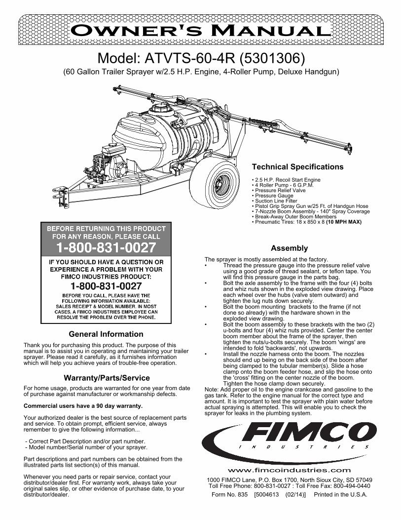
Form No. 835 [5004613 (02/14)] Printed in the U.S.A. Assembly The sprayer is mostly assembled at the factory. Thread the pressure gauge into the pressure relief valve • using a good grade of thread sealant, or teflon tape. You will find this pressure gauge in the parts bag. Bolt the axle assembly to the frame with the four (4) bolts • and whiz nuts shown in the exploded view drawing. Place each wheel over the hubs (valve stem outward) and tighten the lug nuts down securely. Bolt the boom mounting brackets to the frame (if not • done so already) with the hardware shown in the exploded view drawing. Bolt the boom assembly to these brackets with the two (2) • u-bolts and four (4) whiz nuts provided. Center the center boom member about the frame of the sprayer, then tighten the nuts/u-bolts securely. The boom 'wings' are intended to fold 'backwards', not upwards. Install the nozzle harness onto the boom. The nozzles • should end up being on the back side of the boom after being clamped to the tubular member(s). Slide a hose clamp onto the boom feeder hose, and slip the hose onto the 'cross' fitting on the center nozzle of the boom. Tighten the hose clamp down securely. Note: Add proper oil to the engine crankcase and gasoline to the gas tank. Refer to the engine manual for the correct type and amount. It is important to test the sprayer with plain water before actual spraying is attempted. This will enable you to check the sprayer for leaks in the plumbing system. Model: ATVTS-60-4R (5301306) (60 Gallon Trailer Sprayer w/2.5 H.P. Engine, 4-Roller Pump, Deluxe Handgun) Owner's Manual 1000 FIMCO Lane, P.O. Box 1700, North Sioux City, SD 57049 Toll Free Phone: 800-831-0027 : Toll Free Fax: 800-494-0440 www.fimcoindustries.com General Information Thank you for purchasing this product. The purpose of this manual is to assist you in operating and maintaining your trailer sprayer. Please read it carefully, as it furnishes information which will help you achieve years of trouble-free operation. Warranty/Parts/Service For home usage, products are warranted for one year from date of purchase against manufacturer or workmanship defects. Commercial users have a 90 day warranty. Your authorized dealer is the best source of replacement parts and service. To obtain prompt, efficient service, always remember to give the following information... - Correct Part Description and/or part number. - Model number/Serial number of your sprayer. Part descriptions and part numbers can be obtained from the illustrated parts list section(s) of this manual. Whenever you need parts or repair service, contact your distributor/dealer first. For warranty work, always take your original sales slip, or other evidence of purchase date, to your distributor/dealer. Technical Specifications • 2.5 H.P. Recoil Start Engine • 4 Roller Pump - 6 G.P.M. • Pressure Relief Valve • Pressure Gauge • Suction Line Filter • Pistol Grip Spray Gun w/25 Ft. of Handgun Hose • 7-Nozzle Boom Assembly - 140" Spray Coverage • Break-Away Outer Boom Members • Pneumatic Tires: 18 x 850 x 8 (10 MPH MAX)
Transcript of Owner's Manual - Fimco IndustriesFM835...• 2.5 H.P. Recoil Start Engine • 4 Roller Pump - 6...
Form No. 835 [5004613 (02/14)] Printed in the U.S.A.
AssemblyThe sprayer is mostly assembled at the factory.
Thread the pressure gauge into the pressure relief valve •using a good grade of thread sealant, or teflon tape. You will find this pressure gauge in the parts bag.Bolt the axle assembly to the frame with the four (4) bolts •and whiz nuts shown in the exploded view drawing. Place each wheel over the hubs (valve stem outward) and tighten the lug nuts down securely.Bolt the boom mounting brackets to the frame (if not •done so already) with the hardware shown in the exploded view drawing.Bolt the boom assembly to these brackets with the two (2) •u-bolts and four (4) whiz nuts provided. Center the center boom member about the frame of the sprayer, then tighten the nuts/u-bolts securely. The boom 'wings' are intended to fold 'backwards', not upwards.Install the nozzle harness onto the boom. The nozzles •should end up being on the back side of the boom after being clamped to the tubular member(s). Slide a hose clamp onto the boom feeder hose, and slip the hose onto the 'cross' fitting on the center nozzle of the boom. Tighten the hose clamp down securely.
Note: Add proper oil to the engine crankcase and gasoline to the gas tank. Refer to the engine manual for the correct type and amount. It is important to test the sprayer with plain water before actual spraying is attempted. This will enable you to check the sprayer for leaks in the plumbing system.
Model: ATVTS-60-4R (5301306)(60 Gallon Trailer Sprayer w/2.5 H.P. Engine, 4-Roller Pump, Deluxe Handgun)
Owner's Manual
1000 FIMCO Lane, P.O. Box 1700, North Sioux City, SD 57049Toll Free Phone: 800-831-0027 : Toll Free Fax: 800-494-0440
www.fimcoindustries.com
General InformationThank you for purchasing this product. The purpose of this manual is to assist you in operating and maintaining your trailer sprayer. Please read it carefully, as it furnishes information which will help you achieve years of trouble-free operation.
Warranty/Parts/ServiceFor home usage, products are warranted for one year from date of purchase against manufacturer or workmanship defects.
Commercial users have a 90 day warranty.
Your authorized dealer is the best source of replacement parts and service. To obtain prompt, efficient service, always remember to give the following information...
- Correct Part Description and/or part number. - Model number/Serial number of your sprayer.
Part descriptions and part numbers can be obtained from the illustrated parts list section(s) of this manual.
Whenever you need parts or repair service, contact your distributor/dealer first. For warranty work, always take your original sales slip, or other evidence of purchase date, to your distributor/dealer.
Technical Specifications• 2.5 H.P. Recoil Start Engine• 4 Roller Pump - 6 G.P.M.• Pressure Relief Valve• Pressure Gauge• Suction Line Filter• Pistol Grip Spray Gun w/25 Ft. of Handgun Hose• 7-Nozzle Boom Assembly - 140" Spray Coverage• Break-Away Outer Boom Members• Pneumatic Tires: 18 x 850 x 8 (10 MPH MAX)
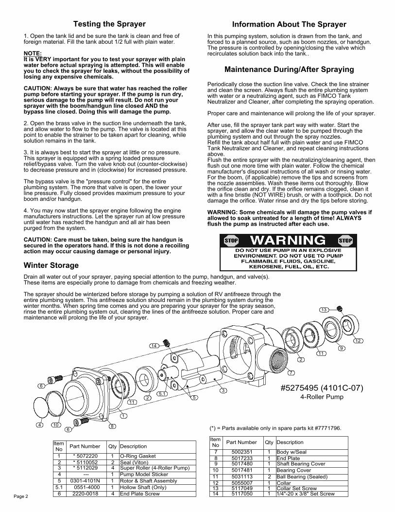
(*) = Parts available only in spare parts kit #7771796.
4-Roller Pump#5275495 (4101C-07)
1/4"-20 x 3/8" Set ScrewCollar Set ScrewCollarBall Bearing (Sealed)Bearing CoverShaft Bearing CoverEnd PlateBody w/Seal
Description
Rotor & Shaft Assembly
End Plate ScrewHollow Shaft (Only)
Pump Model StickerSuper Roller (4-Roller Pump)Seal (Viton)O-Ring Gasket
DescriptionQtyPart NumberNoItem
2220-0018 0551-40000301-4101N
* 5112029* 5110052* 5072220
5
65.1
2
43
1
---1
41
42
1
1
QtyPart NumberNoItem
51170505117049505500750311135017481501748050172335002351
11
141312
8
109
7
2
111
1
11
1
64 10
6
8
1
112
5.15
14
3
13
2
7
119
12
Page 2
1. Open the tank lid and be sure the tank is clean and free of foreign material. Fill the tank about 1/2 full with plain water.
NOTE:It is VERY important for you to test your sprayer with plain water before actual spraying is attempted. This will enable you to check the sprayer for leaks, without the possibility of losing any expensive chemicals.
CAUTION: Always be sure that water has reached the roller pump before starting your sprayer. If the pump is run dry, serious damage to the pump will result. Do not run your sprayer with the boom/handgun line closed AND the bypass line closed. Doing this will damage the pump.
2. Open the brass valve in the suction line underneath the tank, and allow water to flow to the pump. The valve is located at this point to enable the strainer to be taken apart for cleaning, while solution remains in the tank.
3. It is always best to start the sprayer at little or no pressure. This sprayer is equipped with a spring loaded pressure relief/bypass valve. Turn the valve knob out (counter-clockwise) to decrease pressure and in (clockwise) for increased pressure.
The bypass valve is the "pressure control" for the entire plumbing system. The more that valve is open, the lower your line pressure. Fully closed provides maximum pressure to your boom and/or handgun.
4. You may now start the sprayer engine following the engine manufacturers instructions. Let the sprayer run at low pressure until water has reached the handgun and all air has been purged from the system.
CAUTION: Care must be taken, being sure the handgun is secured in the operators hand. If this is not done a recoiling action may occur causing damage or personal injury.
Information About The SprayerIn this pumping system, solution is drawn from the tank, and forced to a planned source, such as boom nozzles, or handgun. The pressure is controlled by opening/closing the valve which recirculates solution back into the tank..
Testing the Sprayer
Periodically close the suction line valve. Check the line strainer and clean the screen. Always flush the entire plumbing system with water or a neutralizing agent, such as FIMCO Tank Neutralizer and Cleaner, after completing the spraying operation.
Proper care and maintenance will prolong the life of your sprayer.
After use, fill the sprayer tank part way with water. Start the sprayer, and allow the clear water to be pumped through the plumbing system and out through the spray nozzles.Refill the tank about half full with plain water and use FIMCO Tank Neutralizer and Cleaner, and repeat cleaning instructions above.Flush the entire sprayer with the neutralizing/cleaning agent, then flush out one more time with plain water. Follow the chemical manufacturer's disposal instructions of all wash or rinsing water.For the boom, (if applicable) remove the tips and screens from the nozzle assemblies. Wash these items out thoroughly. Blow the orifice clean and dry. If the orifice remains clogged, clean it with a fine bristle (NOT WIRE) brush, or with a toothpick. Do not damage the orifice. Water rinse and dry the tips before storing.
WARNING: Some chemicals will damage the pump valves if allowed to soak untreated for a length of time! ALWAYS flush the pump as instructed after each use.
Maintenance During/After Spraying
Drain all water out of your sprayer, paying special attention to the pump, handgun, and valve(s). These items are especially prone to damage from chemicals and freezing weather.
The sprayer should be winterized before storage by pumping a solution of RV antifreeze through the entire plumbing system. This antifreeze solution should remain in the plumbing system during the winter months. When spring time comes and you are preparing your sprayer for the spray season, rinse the entire plumbing system out, clearing the lines of the antifreeze solution. Proper care and maintenance will prolong the life of your sprayer.
Winter Storage
A21
30
3315
11
14
14
26
35.8
135.2
35.6
35.435.3
35.135.6
35.5
35.7
8 20 20
31
40
26
126
17
63
3
16
12
12
37
36
31
28
4
13
32
23
39
9
6
710
29
39
253
27
2
23101818
2827
3
3834.734.6
34.534.1
34.434.3
34.2
5
71919
9 20 20
6 20 20
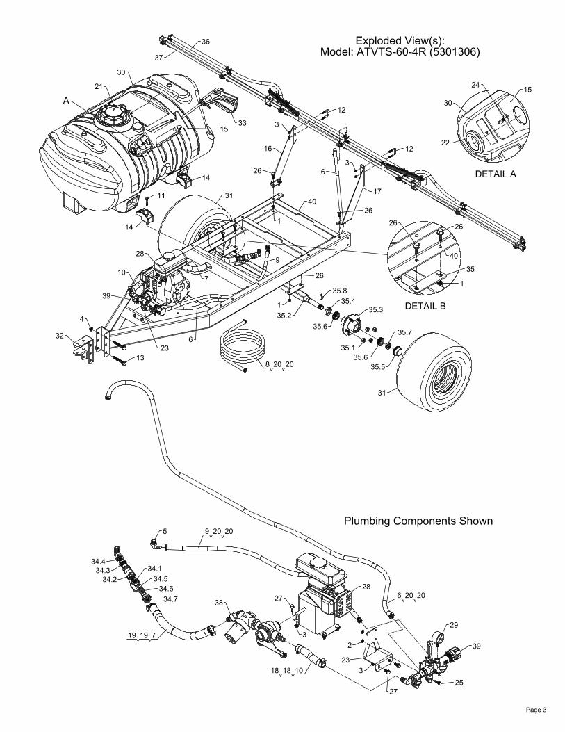
Plumbing Components Shown
DETAIL A
22
24 15
30
DETAIL B
26
1
35
40
26
Page 3
Exploded View(s):Model: ATVTS-60-4R (5301306)
Boom Clamp Assembly (7xs)
7-Nozzle Boom Assembly2.1
2.2
2.5
1.6
50161571.3.4
1.5.1
1.4.51.4.41.4.31.4.21.4.1
1.3.5
1.5
1.4
505611352776895018371501615750462195116019505611452776905018371
1.3.31.3.21.3.1
Item
1.3
1.11
1.2
NoPart
5046219511601950561155277691502051050511445277696Number
1.5.2
1.5.51.5.3
1.5.4
1.5.11.2
Single Hose Shank (3/8" Hose)"ELL" Nozzle Sub-Assembly (3/8")Air-Induction XR Flat Spray Tip (AIXR11002VP)Seat Washer (QJ Caps)Quick TeeJet Cap ONLY (Yellow)Nozzle Strainer, Red (50 Mesh)Double Hose Shank (3/8" Hose)"TEE" Nozzle Sub-Assembly (3/8")Air-Induction XR Flat Spray Tip (AIXR11002VP)Seat Washer (QJ Caps)Quick TeeJet Cap ONLY (Yellow)Nozzle Strainer, Red (50 Mesh)Triple Hose Shank (3/8" Hose)"Cross" Nozzle Sub-Assembly (3/8")Hose, 3/8"-1 Brd. x 19-3/8"
7-Nozzle Harness (3/8")
1
1
1
12
1
4
11
1
Hose Clamp, 3/8"
DescriptionQty
1
11
1
121
4
1.3.41.3.51.3.3
2.4
1.21.4.41.4.51.4.3
1.4.11.4.2
1.11.7
2.8
1.3.11.3.2
2.2
2.2
2.12.3
Outer Boom Weldment (LH) (1" Sq Tube)Outer Boom Weldment (RH) (1" Sq Tube)Center Boom Weldment 1" Sq. TubeSquare Cap, Black (1" Square Tube)
3/8"-16 Flange Locknut (Grade F)3/8"-16 Hex Whiz (Flange) Locknut
Boom Clamp Assembly (1in Sq.)Air-Induction XR Flat Spray Tip (AIXR11002VP)
Quick TeeJet Cap ONLY (Yellow)Nozzle Strainer, Red (50 Mesh)
1.7
250203471.7
527783752778365277838504610650341695019228500634550062595277780
2.82.72.62.52.42.32.22.12
1
2
11
2
64
2
1
5277923
Number
1.61.5.51.5.41.5.31.5.2No
Item
5018371501615750462195116019
Part
1
17
1
Qty1
Hose, 3/8"-1 Brd. x 21"
H.H.C.S., 3/8"-16 x 2 1/2"Extension Spring
7-Nozzle Boom Assembly
2.2
Seat Washer (QJ Caps)
Description
1.2
2.6 2.1
2.2 2.22.3 2.1
2.4
2.7
1.11.2
2.5
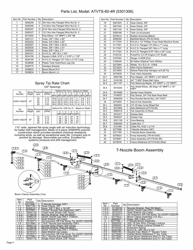
Gallons Per 1000 Sq. Ft. - Based on Water
MPH
Pressure
Pressure
AIXR11002VP
Number
AIXR11002VP
Number
Tip
Tip
18"
HeightSpray
18"
HeightSpray
.27.34.45.680.2040
Gallons Per Acre - Based on Water
(GPM)Capacity
(GPM)Capacity
0.2040
302015
(psi)
0.170.140.12
302015
(psi)
0.170.140.12
29.859.6
MPH
.58
.48
.41
2
50.441.635.6MPH
1MPH
25.220.817.8
2
.23
.19
.16MPH
5
11.910.18.37.1
MPH5
14.919.8
.29
.24
.20MPHMPH
.39
.32
.27
3 4
12.610.4
MPHMPH
16.813.811.8
3
8.9
4
7.49.98.46.95.9
MPH6
6.35.24.5
8
Spray Tip Rate Chart(20" Spacing)
110° wide, tapered flat spray angle with air induction technology for better drift management. Made of 2-piece UHMWPE polymer
construction which provides excellent chemical resistance, including acids, as well as exceptional wear life. Compact size to
prevent tip damage. Removable pre-orifice. Excellent for systemic products and drift management.
Page 4
Parts List, Model: ATVTS-60-4R (5301306)
Item No Part Number Qty Description1 5006259 12 3/8-16nc Hex Flanged Whiz Nut Gr. 52 5006306 4 1/4-20nc Hex Flanged Whiz Nut Gr. 53 5006307 10 5/16-18nc Hex Flanged Whiz Nut Gr. 54 5006337 2 1/2-13nc Hex Flanged Whiz Nut Gr. 55 5010202 1 Poly Elbow, 1/2" MNPT x 3/8" HB6 5020131 1 Hose, 3/8"-1 Brd. x 90"7 5020233 1 Hose, 3/4"-2 Brd. x 20"8 5020527 1 Hose, 3/8"-1 Brd. x 25 Ft.9 5020530 1 Hose, 3/8"-1 Brd. x 51"
10 5020540 1 Hose, 5/8"-1 Brd. x 7"11 5034101 4 H.H.C.S., 3/8"-16 x 1 3/4"12 5034159 2 Square U-Bolt, 5/16" x 1 5/16" x 1 7/8"13 5034700 2 H.H.C.S. Flanged 1/2"-13nc x 3 1/2" Long14 5038698 4 Plastic Tank Hold-Down Leg Clip15 5038775 1 Handgun Bracket16 5038833 1 Boom Mount R.H.17 5038834 1 Boom Mount L.H.
Item No Part Number Qty Description18 5051023 2 Hose Clamp, 5/8"19 5051024 2 Hose Clamp, 3/4"20 5051144 6 Hose Clamp, 3/8"21 5058188 1 Tank Lid w/Lanyard22 5075014 2 Rubber Grommet (Black)23 5095350 1 Manifold Mount (TR-40-GAS)24 5117234 2 #10-24 x 1/2" Phillips Truss Head Machine Screw25 5117301 4 H.H.C.S. Flanged 1/4"-20nc x 1" Long26 5117307 8 H.H.C.S. Flanged 3/8"-16nc x 1" Long27 5117323 6 H.H.C.S. Flanged 5/16"-18nc x 3/4" Long28 5152104 1 PowerPro 2.5 HP Engine (1/2" Shaft)29 5167004 1 Gauge, 0-200# (Dry)30 5169249 1 60 Gallon Elliptical Tank (White)31 5272464 2 Wheel, 18 x 9.5 x 8 - 4-Bolt32 5273204 1 Hitch Clevis Weldment33 5273959 1 Deluxe Pistol-Grip Handgun w/X-26 Tip34 5274939 1 Tank Valve Assembly
34.1 5005196 1 Poly Adapter, 3/4" MNPT x 3/4" MGHT34.2 5143190 1 3/4" "T-800" Brass Ball Valve34.3 5011147 1 Poly Reducing Nipple, 3/4" MNPT x 1/2" MNPT
34.4 5010243 1 Poly Street Elbow, (90 Deg) 1/2" MNPT x 1/2" FNPT
34.5 5016066 1 Garden Hose Washer34.6 5149037 1 Poly Swivel, 3/4" Flat Seat Hose Barb34.7 5006209 1 Poly Knurled Swivel Nut, 3/4" FGHT35 5274955 1 Axle & Hub Assembly
35.1 5006301 8 1/2"-20 Hex Cone Wheel Nut35.2 5274954 1 Axle Weldment (ATVTS-60)35.3 5085018 2 Hub Assembly (4-Stud)35.4 5072471 2 Grease Seal35.5 5046327 2 Grease Cap35.6 5031139 4 Cone Bearing35.7 5006300 2 Castle Nut, 1"35.8 5101081 2 Cotter Pin, 5/32" x 2-1/4"36 5277696 1 7-Nozzle Harness (3/8")37 5277780 1 7-Nozzle Boom Assembly38 5278023 1 Pump Assembly (TR-40-GAS)39 5278067 1 Valve Assembly (ATVTS-60-4R)40 5278078 1 Frame Weldment (ATVTS-60) (Red)
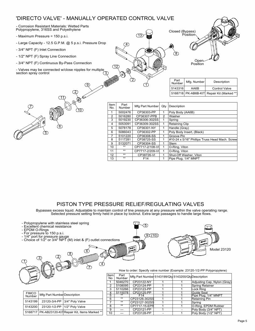
'DIRECTO VALVE' - MANUALLY OPERATED CONTROL VALVE
513207151172815101220508604350781785053091501923050162805002476Number
section spray control- Valves may be connected w/close nipples for multiple
- 3/4" NPT (F) Continuous By-Pass Connection
- 1/2" NPT (F) Spray Line Connection
- 3/4" NPT (F) Inlet Connection
- Large Capacity - 12.5 G.P.M. @ 5 p.s.i. Pressure Drop
- Maximum Pressure = 150 p.s.i.
Polypropylene, 316SS and Polyethylene- Corrosion Resistant Materials: Wetted Parts
5
7
12
9
6
112
10
2
9
1213
1110
****
****
6
87
543
3
ItemNo.1
Part
4
#10-24 x 5/16" Phillips Truss Head Mach. Screw
Repair Kit (Marked **)
Position
2CP36307-PPB
F14CP38726-VI
CP7717-2/209-VICP7717-2/108-VI
CP36304-SSCP38725-SSCP36308-SSCP36302-PPCP36301-NY
CP36309-302SSCP36306-302SS
1
11
11
111
11
1
CP36303-PP
Mfg Part Number
21
Qty
1Washer
Pipe Plug, 1/4" MNPTShut-Off Washer, Viton
Poly Body Insert, (Black)Handle (Gray)Retaining Clip
Stem
O-Ring, VitonO-Ring, Viton
Groove Pin
Spring
Poly Body (AA6B)
PK-AB6B-KIT
Mfg. Number
5168718
Description
5143316
NumberPart
AA6B
13 PositionClosed (Bypass)
8
Open
Control Valve
Description
PISTON TYPE PRESSURE RELIEF/REGULATING VALVES
How to order: Specify valve number (Example: 23120-1/2-PP Polypropylene)
Model 23120
Selected pressure setting firmly held in place by locknut. Extra large passages to handle large flows.Bypasses excess liquid. Adjustable to maintain control of line pressure at any pressure within the valve operating range.
5115078511026651080955046270
PK-AB23120-KIT
23120-1/2-PP
23120-3/4-PP
Mfg Part Number
- Choice of 1/2" or 3/4" NPT (M) inlet & (F) outlet connections- 1/4" port for pressure gauge- For pressure to 150 p.s.i.
- Excellent chemical resistance- Polypropylene with stainless steel spring
5143199
5168717
5143200
NumberFIMCO
13
- EPDM O-Rings
6
Repair Kit, Items Marked **
3/4" Poly Valve
1/2" Poly Valve
Description
28
**7
1098
------**
Item
74
PartNumber
3
56
4
12
No
****
Poly Body (1/2" NPT)Poly Body (3/4" NPT)O-Ring, EPDM Rubber
Retaining PinPipe Plug, 1/4" MNPT
Spring RetainerAdjusting Cap, Nylon (Gray)
5143199/Qty
1CP23127-302SS
CP23128-PPCP23121-PP
CP7717-15-EPR
-11
CP23126-302SS
CP23125-PPCP23123-PPCP23124-PPCP23122-NY
Mfg Part Number
F14
1
111
11
Spring1
1
1-
5143200/Qty
1
111
11
Description
Guide SeatLock Ring
9
5
(10)
Page 5

to Handgun
1
Inlet
2
4
to Boom
1
Return to Tank
3
57
6
Valve Assembly #5278067
Directo-Valve (AA6B)Pressure Relief Valve, (3/4" NPT)
Poly Reducing Nipple, 3/4" MNPT xPoly Tee, 1/2" FNPTPoly Elbow, 3/4" MNPT x 3/8" HBPoly Elbow, 1/2" MNPT x 5/8" HBPoly Elbow, 1/2" MNPT x 3/8" HB
150102304
51433165143199
5011147
76
5 1/2" MNPT11
1
501020650102045010202
Number
3
1
NoItem Part
2
DescriptionQty
11
2
Pump Assembly #5278023
8
2
5
9.1
9.310
6
4
6
9.2
9.4
3
Poly Fitting, 3/4" MNPT x 3/4" HBPoly Fitting, 3/4" MNPT x 5/8" HBRubber-Headed Machine Screw Bumper (#10-24)
5/16"-18 x 1/2" Hex Flanged Bolt (Grd. 5)Poly Close Nipple, 3/4" MNPT45 Degree Poly Street Elbow, 3/4" NPT#10-24 Hex Whiz (Flange) Locknut
7150671267
109.49.39.29.1
1
4
89
5275495504608851163235072229505812551163225067127
4-Roller PumpStrainer Cap40 Mesh ScreenEPDM GasketStrainer Bowl3/4" Black Poly Strainer
1
1
11
1
11
QtyNoItem
3
56
4
12
Part
504000450387305034604501114050102495006186Number
Torque Bracket
Description
1
12
2
21
Page 6