Owner’s manual ENGLISHscramblerducati.com/immagini/manual//Scrambler800_GBR_MY15_ED… ·...
187
Transcript of Owner’s manual ENGLISHscramblerducati.com/immagini/manual//Scrambler800_GBR_MY15_ED… ·...


Owner’s manualENGLISH
1

This manual forms an integral part of the motorcycle and must be kept with it for its whole service life.If the motorcycle is resold, the manual must always be handed over to the new owner.This manual must be preserved with care. If it is lost or becomes damaged, contact a Ducati Dealer orauthorised Service Centre without delay to obtain a new copy of the manual.
The quality standards and safety of Ducati motorcycles are steadily improved as new design solutions,equipment and accessories are developed. While the information contained in this manual is current at thetime of going to print, Ducati Motor Holding S.p.A. reserves the right to make changes at any time withoutnotice and without any obligations. For this reason, the illustrations in this manual might differ from yourmotorcycle.
Any and all reproduction or spreading of the contents herein in whole or in part is forbidden. All rights reservedto Ducati Motor Holding S.p.A. Any request for written authorisation shall be addressed to this company,specifying the reasons for request.
Enjoy your ride!
2
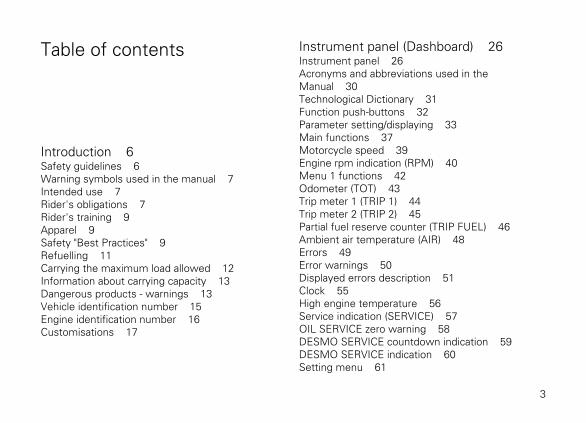
Table of contents
Introduction 6Safety guidelines 6Warning symbols used in the manual 7Intended use 7Rider's obligations 7Rider's training 9Apparel 9Safety "Best Practices" 9Refuelling 11Carrying the maximum load allowed 12Information about carrying capacity 13Dangerous products - warnings 13Vehicle identification number 15Engine identification number 16Customisations 17
Instrument panel (Dashboard) 26Instrument panel 26Acronyms and abbreviations used in theManual 30Technological Dictionary 31Function push-buttons 32Parameter setting/displaying 33Main functions 37Motorcycle speed 39Engine rpm indication (RPM) 40Menu 1 functions 42Odometer (TOT) 43Trip meter 1 (TRIP 1) 44Trip meter 2 (TRIP 2) 45Partial fuel reserve counter (TRIP FUEL) 46Ambient air temperature (AIR) 48Errors 49Error warnings 50Displayed errors description 51Clock 55High engine temperature 56Service indication (SERVICE) 57OIL SERVICE zero warning 58DESMO SERVICE countdown indication 59DESMO SERVICE indication 60Setting menu 61
3

ABS control uni enabling/disabling 64Battery voltage 67Instrument panel back-lighting setting(B.LIGHT) 69Clock setting function (CLOCK) 71Pin Code 74Changing the PIN CODE 78Setting the units of measurement 83Light control 90Immobilizer system 93Keys 94Operation 95Duplicate keys 96Entering PIN CODE function for overridingpurposes 97
Controls 101Position of motorcycle controls 101Key-operated ignition switch and steeringlock 102Left-hand switch 103Clutch lever 104Right-hand switch 107Throttle twistgrip 108Front brake lever 109
Rear brake pedal 110Gear change pedal 111Adjusting the position of the gearchange pedal andrear brake pedal 112
Main components and devices 114Position on the vehicle 114Tank filler plug 115Seat lock 116Side stand 117USB connection 118Adjusting the rear shock absorber 119
Riding the motorcycle 121Running-in recommendations 121Pre-ride checks 123ABS device 125Starting the engine 126Moving off 128Braking 129Stopping the motorcycle 131Parking 132Refuelling 133Tool kit and accessories 134
4
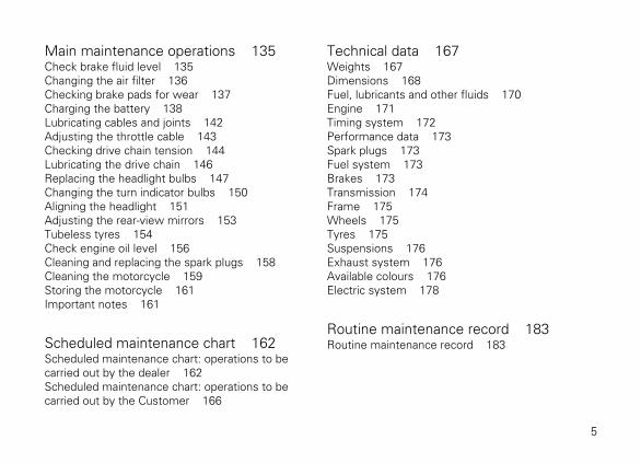
Main maintenance operations 135Check brake fluid level 135Changing the air filter 136Checking brake pads for wear 137Charging the battery 138Lubricating cables and joints 142Adjusting the throttle cable 143Checking drive chain tension 144Lubricating the drive chain 146Replacing the headlight bulbs 147Changing the turn indicator bulbs 150Aligning the headlight 151Adjusting the rear-view mirrors 153Tubeless tyres 154Check engine oil level 156Cleaning and replacing the spark plugs 158Cleaning the motorcycle 159Storing the motorcycle 161Important notes 161
Scheduled maintenance chart 162Scheduled maintenance chart: operations to becarried out by the dealer 162Scheduled maintenance chart: operations to becarried out by the Customer 166
Technical data 167Weights 167Dimensions 168Fuel, lubricants and other fluids 170Engine 171Timing system 172Performance data 173Spark plugs 173Fuel system 173Brakes 173Transmission 174Frame 175Wheels 175Tyres 175Suspensions 176Exhaust system 176Available colours 176Electric system 178
Routine maintenance record 183Routine maintenance record 183
5
Introduction
Safety guidelinesWe would like to welcome you among Ducatienthusiasts, and congratulate you on your excellentchoice of motorcycle. We think you will ride yourDucati motorcycle for long journeys as well as shortdaily trips. Ducati Motor Holding S.p.A. wishes yousmooth and enjoyable riding.
Your motorcycle is the result of Ducati Motor HoldingS.p.A.'s on-going research and development efforts.It is important that you preserve its quality standardby strictly observing the maintenance plan and usinggenuine spare parts. This manual providesinstructions on minor maintenance operations. Majormaintenance operations are described in theWorkshop Manual available to Ducati AuthorisedService Centres.In your own interest, for your safety and in order toguarantee product reliability, you are strongly advisedto refer to our authorised Dealers and Service Centres
for any operations listed in the scheduledmaintenance chart, see page 162.
Our highly skilled staff have access to specialimplements and appropriate equipment required toperform any servicing job at best, and use Ducatioriginal spare parts only as the best guarantee for fullinterchangeability, smooth running and long life.
All Ducati motorcycles come with a Warranty Card.The warranty does not apply to motorcycles used inracing competitions.Tampering with or altering any components, evenpartially, will make the warranty null and voideffective immediately. Improper or poormaintenance, using other than original spare parts orparts not expressly approved by Ducati may invalidateyour warranty rights and lead to damage or loss ofperformance.
Your safety and that of other road users are veryimportant. Ducati Motor Holding S.p.A. recommendsthat you ride responsibly.Before using your motorcycle for the first time, readthis entire manual carefully and closely follow theguidelines outlined in it. The manual provides fullinformation on proper motorcycle operation and
6

maintenance. In case of any doubts, please contact aDealer or Authorised Service Centre.
Warning symbols used in the manualSeveral kinds of warnings are used as an alert of thepossible hazards for you or other persons such as:
- Safety labels on the motorcycle;- Safety messages preceded by a warning symbol
and either WARNING or IMPORTANT.
WarningFailure to comply with these instructions may
put you at risk, and could lead to severe injury or evendeath of the rider or other persons.
ImportantPossibility of damaging the motorcycle and/or
its components.
NoteAdditional information about the current
operation.
The terms RIGHT and LEFT are referred to themotorcycle viewed from the riding position.
Intended use
WarningThis motorcycle is designed for on-road use,
may be used occasionally on dirt trail. Usage inconditions for which it was not designed (e.g. heavyoff-road use) can lead to loss of control of themotorcycle, increasing the risk of a crash.
WarningThis motorcycle may not be used to tow any
trailers or with a side-car attached; this can lead toloss of control and result in an accident.
This motorcycle carries the rider and can carry apassenger.
WarningThe total weight of the motorcycle in running
order including rider, passenger, luggage andadditional accessories should not exceed 365kg/805lb.
Rider's obligationsAll riders must hold a valid licence.
7

WarningRiding without a licence is illegal and is
prosecuted by law. Always make sure you have yourlicence with you when riding. Do not letinexperienced riders or persons without a validlicence use your motorcycle.
Do not ride under the influence of alcohol and/ordrugs.
WarningRiding under the influence of alcohol and/or
drugs is illegal and is prosecuted by law.
Do not take prescription or other drugs before ridingunless you have consulted your doctor about theirside effects.
WarningSome medications and drugs may cause
drowsiness or other effects that slow down reactiontime and the rider's ability to control the motorcycle,possibly leading to an accident.
Some states require vehicle insurance.
WarningCheck your state laws. Obtain insurance
coverage and keep your insurance document securewith the other motorcycle documents.
To protect rider and passenger safety, some statesmandate the use of a certified helmet.
WarningCheck your state laws. Riding without a helmet
may be punishable by law.
WarningRiders without helmets are more likely to suffer
severe bodily injury or die if they are in an accident.
WarningCheck that your helmet complies with safety
specifications, permits good vision, is the right sizefor your head, and carries a certification labelindicating that it conforms to the standards in force inyour state. Road traffic laws differ from state to state.Learn about traffic laws in your state before riding andalways obey them.
8

Rider's trainingAccidents are frequently due to inexperience. Riding,manoeuvres and braking must be performed in adifferent way than on the other vehicles.
WarningUntrained riders or a wrong use of the vehicle
may lead to loss of control, serous injuries or evendeath.
ApparelRiding gear is very important for safety. Unlike cars,a motorcycle offers no impact protection in anaccident.
Proper riding gear includes helmet, eye protection,gloves, boots, long sleeve jacket and long trousers.
- The helmet must meet the requirements listedat page 7; if your helmet does not have a visor,use suitable eye wear;
- Use five-finger gloves made from leather orabrasion-resistant material;
- Riding boots or shoes must have non-slip solesand offer ankle protection;
- Jacket, trousers or riding suit must be made fromleather or abrasion-resistant material and havehigh-visibility colours and inserts.
ImportantNever wear loose clothing, items or accessories
that may become tangled in motorcycle parts.
ImportantFor your safety, always wear suitable protective
gear, regardless of season and weather.
ImportantHave your passenger wear proper protective
clothing.
Safety "Best Practices"These few simple operations are critical to peoplesafety and to preserving the full performance of yourmotorcycle. Never forget to perform them before,while and after riding.
9

ImportantClosely follow the indications provided at
chapter "Riding the motorcycle" during the running-inperiod.Failure to follow these instructions releases DucatiMotor Holding S.p.A. from any liability whatsoever forany engine damage or shorter engine life.
WarningBefore riding your motorcycle, become familiar
with the controls you will need to use when riding.
Perform the checks recommended in this manualbefore each ride (see page 126).
WarningFailure to carry out these checks before riding
may lead to motorcycle damage and injury to riderand/or passenger.
WarningStart the engine outdoors or in a well ventilated
area. The engine should never be started or runindoors.Exhaust gases are poisonous and may lead to loss ofconsciousness or even death within a short time.Use proper body position while riding and ensure yourpassenger does the same.
ImportantRider must hold the handlebar with both hands
at ALL TIMES while riding.
ImportantBoth rider and passenger should keep their feet
on the footpegs when the motorcycle is in motion.
ImportantThe passenger should always hold on to the
grab handles under the seat with both hands.
10

ImportantBe very careful when tackling road junctions, or
when riding in areas near exits from private grounds,car parks or on slip roads to access motorways.
ImportantBe sure you are clearly visible and do not ride
within the blind spot of vehicles ahead.
ImportantALWAYS signal your intention to turn or pull to
the next lane in good time using the suitable turnindicators.
ImportantPark your motorcycle where no one is likely to
knock against it, and use the side stand. Never parkon uneven or soft ground, or your motorcycle may fallover.
ImportantVisually inspect the tyres at regular intervals for
detecting cracks and cuts, especially on the sidewalls, bulges or large spots that are indicative ofinternal damage. Replace them if badly damaged.Remove any stones or other foreign bodies caught inthe tread.
WarningEngine, exhaust pipes and silencers stay hot
long after the engine is switched off; pay particularattention not to touch the exhaust system with anybody part and do not park the vehicle next toflammable material (wood, leaves etc.).
WarningAlways remove the key when you leave your
motorcycle unattended and make sure it is notaccessible to persons not authorised to use themotorcycle.
RefuellingRefuel outdoors with engine off.Do not smoke or use open flames while refuelling.Be careful not to spill fuel on engine or exhaust pipe.
11
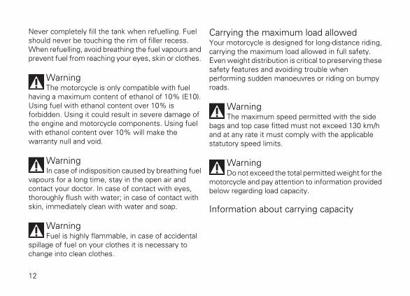
Never completely fill the tank when refuelling. Fuelshould never be touching the rim of filler recess.When refuelling, avoid breathing the fuel vapours andprevent fuel from reaching your eyes, skin or clothes.
WarningThe motorcycle is only compatible with fuel
having a maximum content of ethanol of 10% (E10).Using fuel with ethanol content over 10% isforbidden. Using it could result in severe damage ofthe engine and motorcycle components. Using fuelwith ethanol content over 10% will make thewarranty null and void.
WarningIn case of indisposition caused by breathing fuel
vapours for a long time, stay in the open air andcontact your doctor. In case of contact with eyes,thoroughly flush with water; in case of contact withskin, immediately clean with water and soap.
WarningFuel is highly flammable, in case of accidental
spillage of fuel on your clothes it is necessary tochange into clean clothes.
Carrying the maximum load allowedYour motorcycle is designed for long-distance riding,carrying the maximum load allowed in full safety.Even weight distribution is critical to preserving thesesafety features and avoiding trouble whenperforming sudden manoeuvres or riding on bumpyroads.
WarningThe maximum speed permitted with the side
bags and top case fitted must not exceed 130 km/hand at any rate it must comply with the applicablestatutory speed limits.
WarningDo not exceed the total permitted weight for the
motorcycle and pay attention to information providedbelow regarding load capacity.
Information about carrying capacity
12

ImportantArrange your luggage or heavy accessories in
the lowest possible position and close to motorcyclecentre.
ImportantNever fix bulky or heavy objects to the
handlebar or to the front mudguard as this wouldaffect stability and cause danger.
ImportantBe sure to secure the luggage to the supports
provided on the motorcycle as firmly as possible.Improperly secured luggage may affect stability.
ImportantDo not insert any objects you may need to carry
into the gaps of the frame as these may foul movingparts.
WarningMake sure the tyres are inflated to the proper
pressure and that they are in good condition.
Refer to paragraph "Tyres" on page 154.
Dangerous products - warningsUsed engine oil
WarningProlonged or repeated contact with used engine
oil may cause skin cancer. If working with engine oilon a daily basis, we recommend washing your handsthoroughly with soap immediately afterwards. Keepaway from children.
Brake dust
Never clean the brake assembly using compressedair or a dry brush.
Brake fluid
WarningSpilling brake fluid onto plastic, rubber or
painted parts of the motorcycle may cause damages.Protect these parts with a clean shop cloth beforeproceeding to service the system. Keep away fromchildren.
13

WarningThe fluid used in the brake system is corrosive.
In the event of accidental contact with eyes or skin,wash the affected area with abundant running water.
Coolant
Engine coolant contains ethylene glycol, which mayignite under particular conditions, producing invisibleflames. Although the flames from burning ethyleneglycol are not visible, they are still capable of causingsevere burns.
WarningTake care not to spill engine coolant on the
exhaust system or engine parts.
14
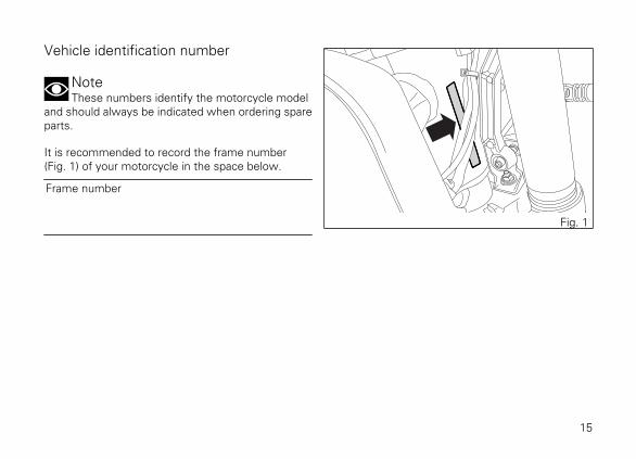
Vehicle identification number
NoteThese numbers identify the motorcycle model
and should always be indicated when ordering spareparts.
It is recommended to record the frame number(Fig. 1) of your motorcycle in the space below.
Frame number
Fig. 1
15

Engine identification number
NoteThese numbers identify the motorcycle model
and should always be indicated when ordering spareparts.
It is recommended to record the number of yourmotorcycle's engine (Fig. 2) in the space below.
Engine number
Fig. 2
16

CustomisationsEach version is a customisation of the SCRAMBLER.The SCRAMBLER is available in four differentcustomisations:
- ICON (A)- URBAN ENDURO (B)- FULL THROTTLE (C)- CLASSIC (D)
Information herein refers to Scrambler ICON.Information on any other customisation (URBANENDURO, FULL THROTTLE, CLASSIC) is indicatedonly when different from the Scrambler ICON.
A
B
C
D
Fig. 3
17
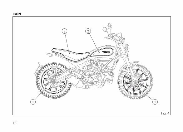
ICON
3 2
1 1
Fig. 4
18

ICON
1) Ten-spoke, light-alloy rims2) Dedicated sticker with logo3) Dedicated seat
19
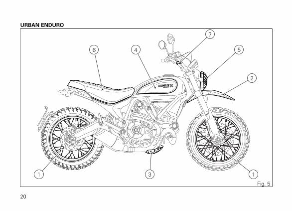
URBAN ENDURO
6 4
7
5
2
1 13
Fig. 5
20

URBAN ENDURO
1) Spoked wheels2) Raised front mudguard3) Sump guard4) Dedicated sticker with logo5) Headlight grille as standard6) Dedicated seat7) Handlebar crosspiece8) Front fork guards
21
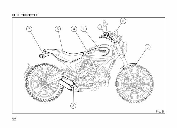
FULL THROTTLE
57 1
3
6
4
2
Fig. 6
22

FULL THROTTLE
1) Dedicated sticker with logo2) Tailpipe as standard (Termignoni)3) Lowered handlebar4) Black anodised side panels5) Dedicated racing seat6) Short front mudguard7) Rear turn indicators with no splash guard
23
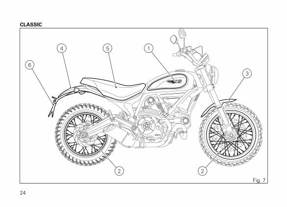
CLASSIC
54
6
1
3
2 2
Fig. 7
24
CLASSIC
1) Dedicated-thickness logo2) Aluminium spoked wheels3) Long, satin-finished aluminium front mudguard4) Long, satin-finished rear mudguard5) Dedicated seat6) Raised number plate holder
25

Instrument panel (Dashboard)
Instrument panel1) LCD.2) REV COUNTER (rpm).It indicates engine rpm value.3) NEUTRAL LIGHT N (GREEN).Comes on when in neutral position.4) HIGH BEAM LIGHT (BLUE).It turns on to indicate that the high beam lights are onand when the flasher is activated.5) ENGINE OIL PRESSURE LIGHT (RED).Comes on when engine oil pressure is too low. Itmust turn on at "KEY-ON", but must turn OFF a fewseconds after the engine has started. It may shortlycome on when the engine is hot, however, it shouldgo out as the engine revs up.
ImportantIf the ENGINE OIL light stays ON, stop the
engine or it may suffer severe damage.
6) FUEL WARNING LIGHT (AMBER YELLOW).Comes on when fuel is low and there are about 4litres of fuel left in the tank.7) TURN INDICATOR LIGHTS (GREEN).A warning light turns on and blinks when the relevantturn indicator is active; when the warning lights blinkat the same time, the HAZARD function is active.8) "ENGINE/VEHICLE DIAGNOSIS - EOBD" LIGHT (AMBER YELLOW).It turns on in the case of "engine" and/or "vehicle"errors and in some cases will lock the engine.
26
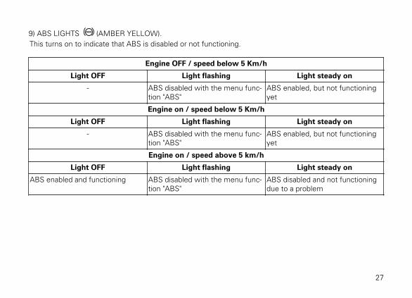
9) ABS LIGHTS (AMBER YELLOW).This turns on to indicate that ABS is disabled or not functioning.
Engine OFF / speed below 5 Km/h
Light OFF Light flashing Light steady on
- ABS disabled with the menu func-tion "ABS"
ABS enabled, but not functioningyet
Engine on / speed below 5 Km/h
Light OFF Light flashing Light steady on
- ABS disabled with the menu func-tion "ABS"
ABS enabled, but not functioningyet
Engine on / speed above 5 km/h
Light OFF Light flashing Light steady on
ABS enabled and functioning ABS disabled with the menu func-tion "ABS"
ABS disabled and not functioningdue to a problem
27
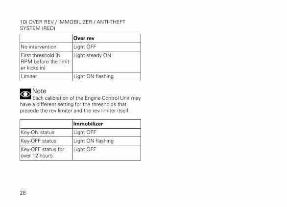
10) OVER REV / IMMOBILIZER / ANTI-THEFTSYSTEM (RED)
Over rev
No intervention Light OFF
First threshold (NRPM before the limit-er kicks in)
Light steady ON
Limiter Light ON flashing
NoteEach calibration of the Engine Control Unit may
have a different setting for the thresholds thatprecede the rev limiter and the rev limiter itself.
Immobilizer
Key-ON status Light OFF
Key-OFF status Light ON flashing
Key-OFF status forover 12 hours
Light OFF
28

7
3
10
6
4 5
8
2
9
10
1
7
Fig. 8
29
Acronyms and abbreviations used in theManualABSAntilock Braking SystemCANController Area NetworkDDADUCATI Data AcquisitionDSBDashboardECUEngine Control Unit
30

Technological DictionaryAnti-lock Braking System (ABS) 9M
ABS 9M system is a two-channel latest-generationsystem that actuates combined braking with anti lift-up function for the rear wheel so as to guarantee notonly a reduced stopping distance, but also a higherstability under braking.
31
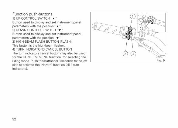
Function push-buttons1) UP CONTROL SWITCH " "Button used to display and set instrument panelparameters with the position " ".2) DOWN CONTROL SWITCH " "Button used to display and set instrument panelparameters with the position " ".3) HIGH-BEAM FLASH BUTTON (FLASH)This button is the high-beam flasher.4) TURN INDICATORS CANCEL BUTTONThe turn indicators cancel button may also be usedfor the CONFIRM MENU function, for selecting theriding mode. Push this button for 3 seconds to the leftside to activate the "Hazard" function (all 4 turnindicators).
4
3
2
1
Fig. 9
32

Parameter setting/displayingUpon key-on, the instrument panel:
- turns on the display backlighting;- activates the rev counter which increases from 0
to 12000 and decreases back to 0;- activates the vehicle speed digits and shows a
counting from 0 to 300 and then back to 0;- turns on the warning lights from right to left.
At the end of the check, the instrument panel displaysthe main screen ("standard screen") showing theavailable functions and turns on the warning lights, ifnecessary.
During this first check stage, if the motorcycle speedexceeds 20 km/h (actual speed), the instrument panelwill stop:
- the display check routine and display thestandard screen containing updated information;
- the warning light check routine and leave ON onlythe warning lights that are actually active at themoment.
Fig. 10
33

Data displayed on the main screen are as follows:
1) Engine speed.2) Motorcycle speed.3) MENU 1 (Odometer, Trip 1, Trip 2, Trip Fuel, Air
temperature, Error warning - only if active).4) Clock.5) SERVICE indication (only if active).6) Setting menu.7) Side stand status.
4 3
1
2
76
5
Fig. 11
34
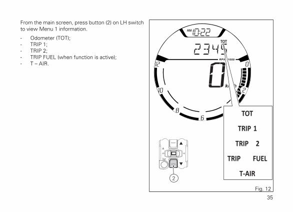
From the main screen, press button (2) on LH switchto view Menu 1 information.
- Odometer (TOT);- TRIP 1;- TRIP 2;- TRIP FUEL (when function is active);- T – AIR.
2
Fig. 12
35

The instrument panel stores Menu 1 settings in useupon KEY-OFF. On the following KEY-ON, previouslystored Menu 1 pages are displayed.In case of sudden and unexpected power OFF, theinstrument panel displays the default settings uponthe following KEY-ON:
- Menu 1 default page = Odometer (TOT).
Upon KEY-ON, for every display layout, instrumentpanel shows for 10 seconds in Menu 1 the"Odometer" page and then shows the page savedupon previous KEY-OFF.
Hold the button (2) for 3 seconds, when actualmotorcycle speed is <= (lower than or equal to) 20km/h, to enter the Setting Menu, where you can setany function.
ImportantYou can enter the SETTING MENU only if
vehicle actual speed is <= (lower than or equal to) 20km/h. Within the SETTING MENU, if vehicle actualspeed exceeds 20 km/h, the instrument panelautomatically quits the menu and shows the standardscreen.
2
Fig. 13
36

Main functionsThe functions displayed in the Standard screen arethe following:Main information
- Motorcycle speed- Engine rpm indication (RPM)- Menu 1 displays the following functions:
- Odometer (TOT)- Trip meter 1 (TRIP 1)- Trip meter 2 (TRIP 2)- Partial fuel reserve counter (TRIP FUEL)- Ambient air temperature (AIR)- Clock
Additional information
- Service indication (SERVICE)- ERROR indication
37
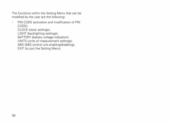
The functions within the Setting Menu that can bemodified by the user are the following:
- PIN CODE (activation and modification of PINCODE);CLOCK (clock settings);LIGHT (backlighting settings);BATTERY (battery voltage indication);UNITS (units of measurement settings);ABS (ABS control unit enabling/disabling);EXIT (to quit the Setting Menu)
38
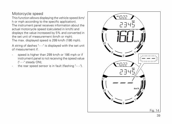
Motorcycle speedThis function allows displaying the vehicle speed (km/h or mph according to the specific application).The instrument panel receives information about theactual motorcycle speed (calculated in km/h) anddisplays the value increased by 5% and converted inthe set unit of measurement (km/h or mph).The max. displayed speed is 299 km/h (186 mph).
A string of dashes "- - -" is displayed with the set unitof measurement if:
- speed is higher than 299 km/h or 186 mph or ifinstrument panel is not receiving the speed value("- - -" steady ON);
- the rear speed sensor is in fault (flashing "- - -").
Fig. 14
39

Engine rpm indication (RPM)This function allows displaying engine rpm.Instrument panel receives rpm value and displays it.The information is displayed by the bargraph fillingfrom the right to the left according to the engine rpm.
Fig. 15
40
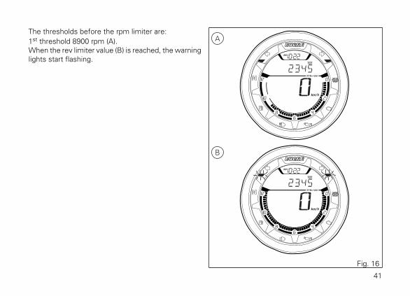
The thresholds before the rpm limiter are:1st threshold 8900 rpm (A).When the rev limiter value (B) is reached, the warninglights start flashing.
A
B
Fig. 16
41

Menu 1 functionsMENU 1 functions are:
- Odometer (TOT);- Trip meter 1 (TRIP 1);- Trip meter 2 (TRIP 2);- Partial fuel reserve counter (TRIP FUEL);- Ambient air temperature (T-AIR).
By pressing button (2) it is possible to view thefunctions of MENU 1.
2
Fig. 17
42

Odometer (TOT)The odometer counts and displays the total distancecovered by the motorcycle with the set unit ofmeasurement (km or mi).The odometer number (in km or miles) is displayedwith the message TOT and the indication of the unitof measurement. When the maximum value isreached (199999 km or 199999 mi) the instrumentpanel will permanently display said value.The odometer value is saved permanently and cannotbe reset under any circumstances.
The reading is not lost in case of a power OFF (BatteryOFF).
Fig. 18
NoteUpon Key-ON, the instrument panel always
shows the Odometer indication for 10 seconds, thenshows the user's settings page.
NoteIf a string of flashing dashes " ----- " is displayed
within odometer function, please contact a DucatiDealer or Authorised Service Centre.
43

Trip meter 1 (TRIP 1)The trip meter counts and displays the partial distancecovered by the motorcycle with the set unit ofmeasurement (km or mi).When the reading exceeds the maximum value of9999.9 km or 9999.9 mi, distance travelled is resetand the meter automatically starts counting from 0again.While the trip meter is displayed, press button (1) for3 seconds to reset TRIP 1.The TRIP 1 counter is automatically reset in case thesystem unit of measurement is changed manually orif the power supply is interrupted (faulty battery): thecounter will then start back from zero, considering thenew units of measurement.
1
Fig. 19
44
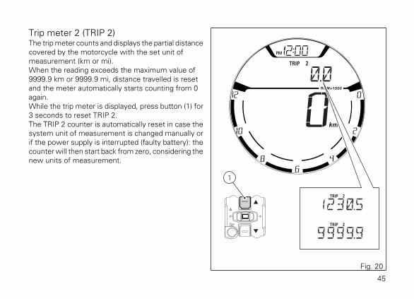
Trip meter 2 (TRIP 2)The trip meter counts and displays the partial distancecovered by the motorcycle with the set unit ofmeasurement (km or mi).When the reading exceeds the maximum value of9999.9 km or 9999.9 mi, distance travelled is resetand the meter automatically starts counting from 0again.While the trip meter is displayed, press button (1) for3 seconds to reset TRIP 2.The TRIP 2 counter is automatically reset in case thesystem unit of measurement is changed manually orif the power supply is interrupted (faulty battery): thecounter will then start back from zero, considering thenew units of measurement.
1
Fig. 20
45
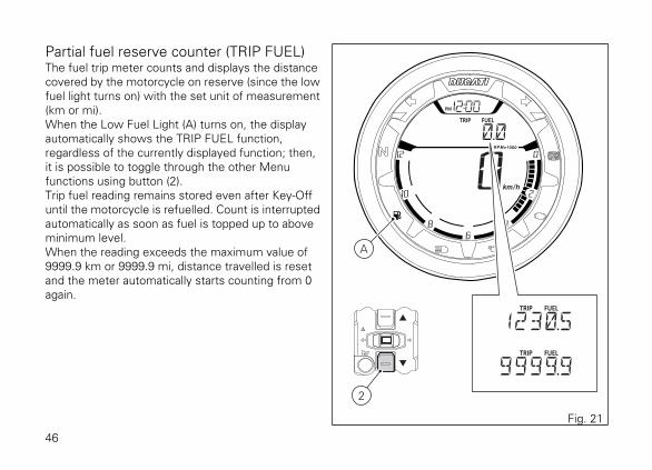
Partial fuel reserve counter (TRIP FUEL)The fuel trip meter counts and displays the distancecovered by the motorcycle on reserve (since the lowfuel light turns on) with the set unit of measurement(km or mi).When the Low Fuel Light (A) turns on, the displayautomatically shows the TRIP FUEL function,regardless of the currently displayed function; then,it is possible to toggle through the other Menufunctions using button (2).Trip fuel reading remains stored even after Key-Offuntil the motorcycle is refuelled. Count is interruptedautomatically as soon as fuel is topped up to aboveminimum level.When the reading exceeds the maximum value of9999.9 km or 9999.9 mi, distance travelled is resetand the meter automatically starts counting from 0again.
A
2
Fig. 21
46

NoteIf the system measurement units are changed
at any moment, or if there is an interruption in thepower supply (Battery Off), the distance travelled isreset and the count starts from zero (considering thenewly set unit of measurement).
47
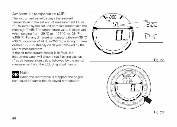
Ambient air temperature (AIR)The instrument panel displays the ambienttemperature in the set unit of measurement (°C or°F), followed by the set unit of measurement and themessage T-AIR. The temperature value is displayedwhen ranging from -39 °C to +124 °C (or -38 °F ÷+255 °F). For any different temperature (below -39 °C(-38 °F) or above +124 °C (+255 °F)) a string of threedashes " - - - " is steadily displayed, followed by theunit of measurement.If the air temperature sensor is in fault, theinstrument panel will show three flashing dashes " - -- " as air temperature value, followed by the unit ofmeasurement and the EOBD light will turn on.
NoteWhen the motorcycle is stopped, the engine
heat could influence the displayed temperature.
Fig. 22
Fig. 23
48
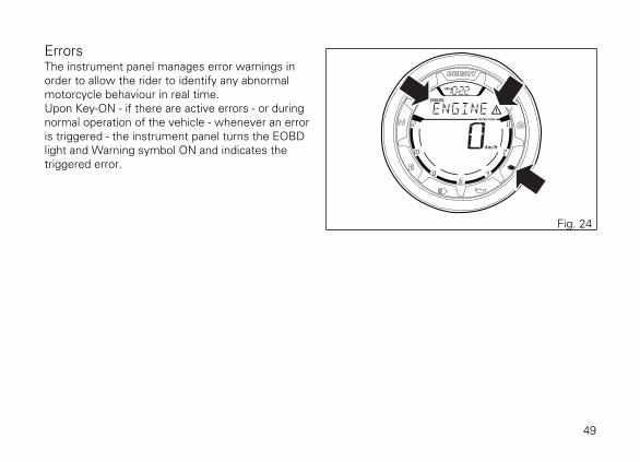
ErrorsThe instrument panel manages error warnings inorder to allow the rider to identify any abnormalmotorcycle behaviour in real time.Upon Key-ON - if there are active errors - or duringnormal operation of the vehicle - whenever an erroris triggered - the instrument panel turns the EOBDlight and Warning symbol ON and indicates thetriggered error.
Fig. 24
49
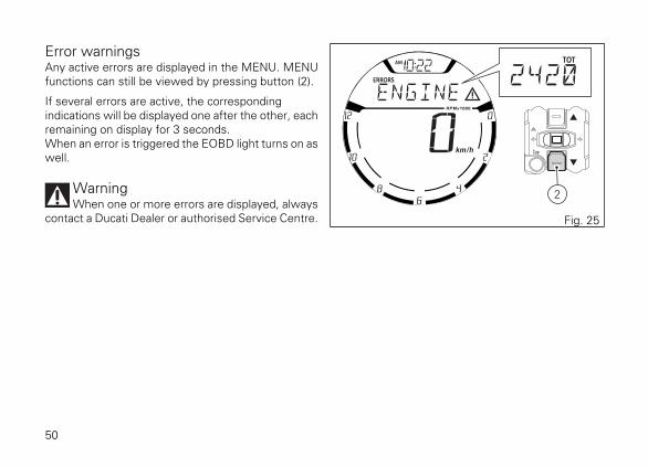
Error warningsAny active errors are displayed in the MENU. MENUfunctions can still be viewed by pressing button (2).
If several errors are active, the correspondingindications will be displayed one after the other, eachremaining on display for 3 seconds.When an error is triggered the EOBD light turns on aswell.
WarningWhen one or more errors are displayed, always
contact a Ducati Dealer or authorised Service Centre.
2
Fig. 25
50
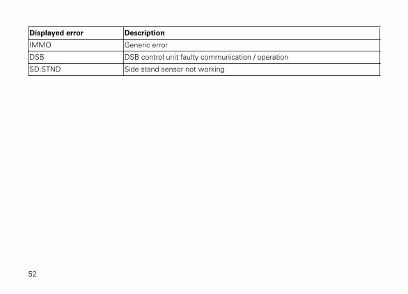
Displayed errors descriptionDisplayed error Description
ENGINE Throttle position sensor malfunction
Throttle motor or relay malfunction (stepper motor)
Pressure sensor malfunction
Engine coolant temperature sensor malfunction
Injection relay malfunction
Ignition coil malfunction
Injector malfunction
Engine rpm sensor malfunction
Lambda sensor or Lambda sensor heater malfunction
Motorcycle starting relay malfunction
Secondary air system valve malfunction
AIR – T. Ambient air temperature sensor malfunction
BATT. Battery voltage too high or too low
FUEL Reserve NTC sensor malfunction
ABS ABS control unit faulty communication / operation
Front and/or rear speed sensor malfunction
CAN CAN line error (communication line across all control units)
51
Displayed error Description
IMMO Generic error
DSB DSB control unit faulty communication / operation
SD.STND Side stand sensor not working
52

Error icons tableWARNING LIGHT / ERROR MESSAGE ERROR
ENGINE Engine control unit
AIR – T. Air temperature sensor
BATT. Battery voltage
SPEED Speed sensor
FUEL Low fuel sensor
ABS ABS control unit
CAN Can Bus OFF
IMMO Immobilizer antenna
DSB Instrument panel control unit
53
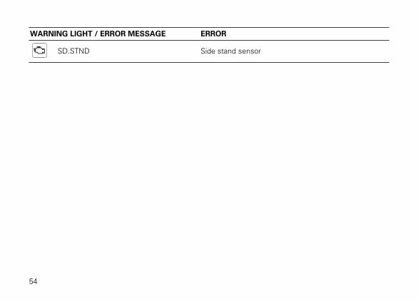
WARNING LIGHT / ERROR MESSAGE ERROR
SD.STND Side stand sensor
54

ClockThe instrument panel receives information about thetime to be displayed.The instrument panel shows the time in the followingformat:
- hh (hours) : mm (minutes);- with the message AM (for values ranging
between 0:00 and 11:59), or PM (for valuesranging between 12:00 and 12:59 and between1:00 and 11:59).
In case of power supply interruption (faulty battery),the clock is reset and starts automatically from "0:00".
Fig. 26
55
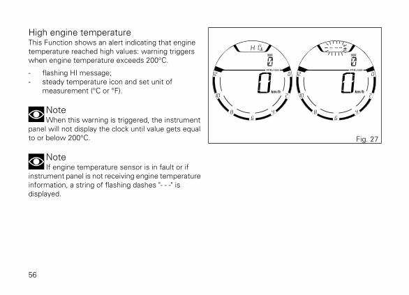
High engine temperatureThis Function shows an alert indicating that enginetemperature reached high values: warning triggerswhen engine temperature exceeds 200°C.
- flashing HI message;- steady temperature icon and set unit of
measurement (°C or °F).
NoteWhen this warning is triggered, the instrument
panel will not display the clock until value gets equalto or below 200°C.
NoteIf engine temperature sensor is in fault or if
instrument panel is not receiving engine temperatureinformation, a string of flashing dashes "- - -" isdisplayed.
Fig. 27
56
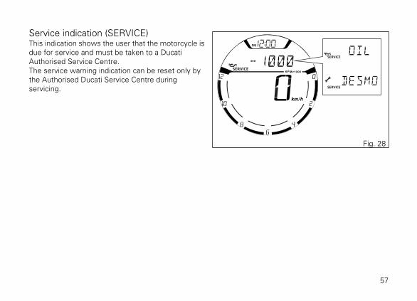
Service indication (SERVICE)This indication shows the user that the motorcycle isdue for service and must be taken to a DucatiAuthorised Service Centre.The service warning indication can be reset only bythe Authorised Ducati Service Centre duringservicing.
Fig. 28
57
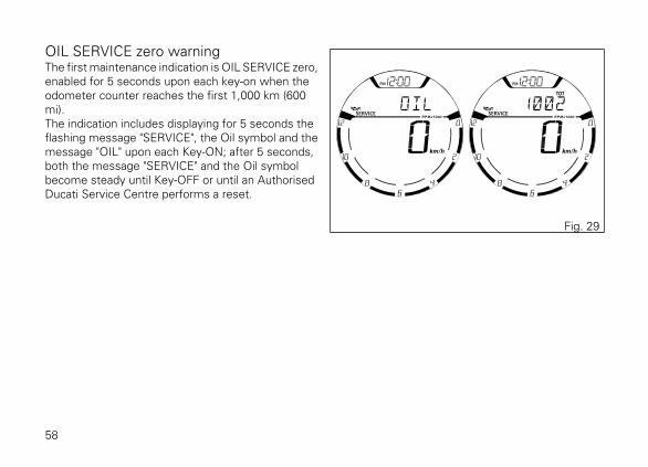
OIL SERVICE zero warningThe first maintenance indication is OIL SERVICE zero,enabled for 5 seconds upon each key-on when theodometer counter reaches the first 1,000 km (600mi).The indication includes displaying for 5 seconds theflashing message "SERVICE", the Oil symbol and themessage "OIL" upon each Key-ON; after 5 seconds,both the message "SERVICE" and the Oil symbolbecome steady until Key-OFF or until an AuthorisedDucati Service Centre performs a reset.
Fig. 29
58

DESMO SERVICE countdown indicationAfter OIL SERVICE zero indication first reset (at 1,000km - 600 mi), the instrument panel activates thecountdown of the kilometres (or miles) left before thefollowing service operation: DESMO SERVICE.The kilometre count indication is shown upon Key-ONfor 2 seconds; when there are 1,000 km (600 miles)left before the next service operation, the indicationturns on upon every Key-ON for 5 seconds.In other words, upon key-on the message "SERVICE"and the Desmo symbol are displayed together withthe indication of the kilometres left before thefollowing service operation.
Fig. 30
59
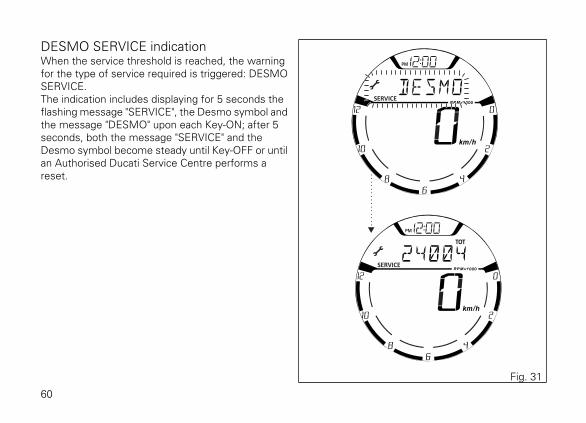
DESMO SERVICE indicationWhen the service threshold is reached, the warningfor the type of service required is triggered: DESMOSERVICE.The indication includes displaying for 5 seconds theflashing message "SERVICE", the Desmo symbol andthe message "DESMO" upon each Key-ON; after 5seconds, both the message "SERVICE" and theDesmo symbol become steady until Key-OFF or untilan Authorised Ducati Service Centre performs areset.
Fig. 31
60
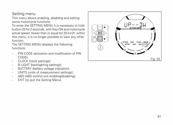
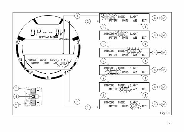
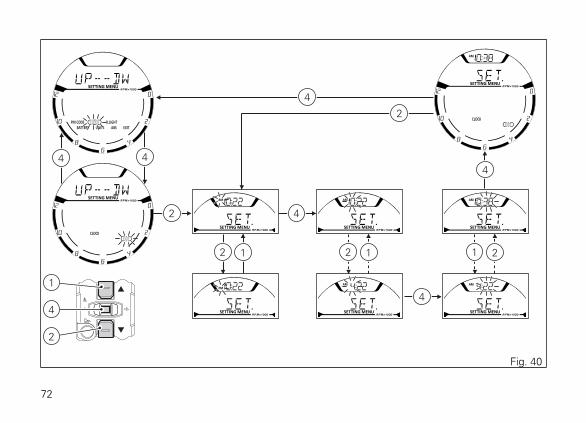
Setting menuThis menu allows enabling, disabling and settingsome motorcycle functions.To enter the SETTING MENU it is necessary to holdbutton (3) for 2 seconds, with Key-ON and motorcycleactual speed ≤ (lower than or equal to) 20 km/h: withinthis menu, it is no longer possible to view any otherfunction.The SETTING MENU displays the followingfunctions:
- PIN CODE (activation and modification of PINCODE);
- CLOCK (clock settings);- B.LIGHT (backlighting settings);- BATTERY (battery voltage indication);- UNITS (units of measurement settings);- ABS (ABS control unit enabling/disabling);- EXIT (to quit the Setting Menu).
2
Fig. 32
61

For safety reasons, the setting menu can beaccessed only when vehicle speed is below or equalto 20 Km/h; if this menu is accessed and vehiclespeed is above 20 Km/h, the instrument panel willautomatically quit it and shift back to main screen.Press buttons (1) and (2) to highlight the customisableparameters one by one: in particular, use button (2)to highlight the following item and button (1) tohighlight the previous item.After highlighting the required parameter, pressbutton (4) to open the corresponding MENU (M)page.If function is not available or temporarily disabled, theMENU page can not be opened.To quit the SETTING MENU you shall highlight "EXIT"and press CONFIRM MENU button (4).
62
4
1
2
2 1
M
2 1
2 1
2 1
2 1
2
1
1
2
4
M4
M4
M4
M4
M4
Fig. 33
63

ABS control uni enabling/disablingThis function allows enabling or disabling the ABSsystem. Enter the SETTING MENU.Select the parameter to be customised (ABS), bypressing button (1) or (2). Once the desired parameteris highlighted, press CONFIRM MENU button (4).When entering the function, the currently set ABSstatus will be displayed:On = enabled, Off = disabled.Menu indicates the available alternative option (RQ):RQ OFF when current status is "On", RQ ON whencurrent status is "Off".To quit the function without changing set status,select EXIT using button (2); when its box is flashing,press button (4).To select a different status than the one set, pressbutton (1); alternative option (RQ) starts flashing inthe Menu.Press button (4) for 3 seconds to confirm. WAIT isdisplayed in the Menu for approx. 5 seconds. Newstatus will then become steady on and "EXIT" box willbe flashing.Press button (4) to quit the function.
64

4
1
2
4
1
4
2
4
Fig. 34
65
NoteBy setting "–" (Off), the ABS will be disabled and
the relevant warning light will start flashing.
ImportantWhen setting the ABS OFF, Ducati
recommends paying particular attention to thebraking and riding style.
If the ABS is in fault, "Err" is displayed when enteringthe function and Menu will indicate "NO RQ", sinceno selection is actually possible. "EXIT" box is flashing.Press button (4) for 3 seconds to quit the function. Fig. 35
4
4
4
Fig. 36
66
Battery voltageThis function allows you to check the motorcyclebattery voltage. Enter the SETTING MENU. SelectBATTERY option, by pressing button (1) or (2). Oncefunction is highlighted, press CONFIRM MENUbutton (4). You open the BATTERY Menu.The information will be displayed as follows:
- if battery voltage is between 11.8 V and 14.9 Vthe reading will be displayed steady;
- if battery voltage is between 0.0 and 11.7 Volt thereading will be displayed with "LOW" messageflashing;
- if battery voltage is between 15.0 and 25.5 Voltthe reading will be displayed with "HIGH"message flashing.
4
4
1
2
Fig. 37
67
If the instrument panel is not receiving battery voltagevalue, a string of three dashes "- - -" is displayed.To quit the menu and go back to Setting Menu mainpage, select EXIT and press button (4).
Fig. 38
68

Instrument panel back-lighting setting(B.LIGHT)This function allows adjusting the backlightingintensity.To set the backlighting enter the SETTING MENU,use buttons (1) and (2) to select "B.LIGHT" and pressbutton (4) to confirm.When accessing the function, the active modeflashes whereas the MENU and EXIT messages willbe steady on.Use buttons (1) and (2) to select the desiredbrightness level (HIGH, MED, LOW) and press button(4) to confirm.Select HIGH to set the display backlighting maximumbrightness - recommended in conditions of strongambient light.Select MED to set the display backlighting mediumbrightness (70%) - recommended in conditions ofmedium/low ambient light.Select LOW to set the display backlighting minimumbrightness (50%) - recommended in conditions of lowambient light and/or during the night.After confirming, the "EXIT" box will start flashing.To exit the menu and go back to the previous page,select "EXIT" and press button (4).
NoteIn the event of an interruption of the power
supply from the Battery, when power is restored, atthe next Key-On, the backlighting will always be setby default to maximum brightness.
69
4
1
2
4
1
4
2
1 2 41 2 4
4 4 4
1 2
1
2
Fig. 39
70
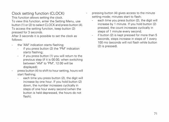
Clock setting function (CLOCK)This function allows setting the clock.To view this function, enter the Setting Menu, usebutton (1) or (2) to select CLOCK and press button (4).To access the setting function, keep button (2)pressed for 3 seconds.After 3 seconds it is possible to set the clock asfollows:
- the "AM" indication starts flashing;- if you press button (2) the "PM" indication
starts flashing;- if you press button (1) you will return to the
previous step (if it is 00:00, when switchingbetween "AM" to "PM", 12:00 will bedisplayed);
- press button (4) to shift to hour setting, hours willstart flashing;- each time you press button (2), the digit will
increase by one hour. If you hold button (2)down, the number increases cyclically insteps of one hour every second (when thebutton is held depressed, the hours do notflash);
- pressing button (4) gives access to the minutesetting mode; minutes start to flash;- each time you press button (2), the digit will
increase by 1 minute. If you hold button (2)pressed, the count increases cyclically insteps of 1 minute every second;
- if button (2) is kept pressed for more than 5seconds, steps increase in steps of 1 every100 ms (seconds will not flash while button(2) is pressed).
71
4
1
2
4
2
2
2
4
4
4
4
1 2 1 1 2
4
Fig. 40
72
To confirm (store) the new set time press button (4).The EXIT box starts flashing, press button (4) to goback to the setting menu.
NoteIn case of battery off, when the Voltage is
restored and upon next Key-On, clock will have to beset again, i.e. it will automatically start counting from00:00.
To quit, press button (4).
73
Pin CodeThis function allows enabling and then modifying a 4-digit PIN code to "temporarily" start the vehicle in caseof Immobilizer system malfunction.The PIN CODE is initially not present in themotorcycle, it must be activated by the user byentering his/her 4-digit PIN in the instrument panel,otherwise the motorcycle cannot be startedtemporarily in the case of a malfunction. To activatethis function, refer to "Entering the PIN CODE"procedure.To change the PIN refer to "Changing the PIN CODE"procedure.In order to temporarily start the motorcycle in case ofmalfunction of the Immobilizer system, please referto the "Vehicle Release" procedure.
WarningThe motorcycle owner must activate (store) the
PIN code; if there is already a stored PIN, contact anAuthorised Ducati Dealer to have the function "reset".To perform this procedure, the Authorised DucatiDealer may ask you to demonstrate that you are theowner of the motorcycle.
74

Entering the PIN CODE
To activate the PIN CODE function and enter yourown PIN CODE you must open the SETTING MENU.Select PIN CODE option, by pressing button (1) or (2).Once function is highlighted, press CONFIRM MENUbutton (4).
NoteIf upon accessing this function, the "O : " (Old)
indication is displayed together with four flashingdashes "- - - -", a PIN code is already stored and theFunction is already active.
When accessing the function, the display will show"N:" (new) followed by four flashing dashes "- - - -".To go back to the previous indication withoutactivating a PIN CODE, press button (2); as soon asthe "EXIT" box starts flashing, press button (4) again.Entering the code:
1) Press button (4), only one digit indicating "0"starts flashing;
2) Each time you press button (2) the displayednumber increases by one (+ 1) up to "9" and thenstarts back from "0";
3) Each time you press the button (1) the displayednumber decreases by one (- 1) up to "1" and thenstarts back from "0";
4) To confirm the number, press the button (4);
Repeat the procedures until you confirm all the digitsof the PIN CODE.
75

4
1
2
2
4
4
4
4
4 4
1
Fig. 41
76

Press button (4) to confirm the fourth and last figure:the 4-digit code starts flashing.To memorise the entered PIN, keep button (4)pressed for 3 seconds.If new settings have been saved, "MEM" will beshown and the "EXIT" box will be flashing.To quit, press button (4).Once the first PIN CODE is stored, this menu page isno longer available and is replaced by the page forchanging the PIN CODE. 4
4
4
2
1
4
1
2
Fig. 42
77
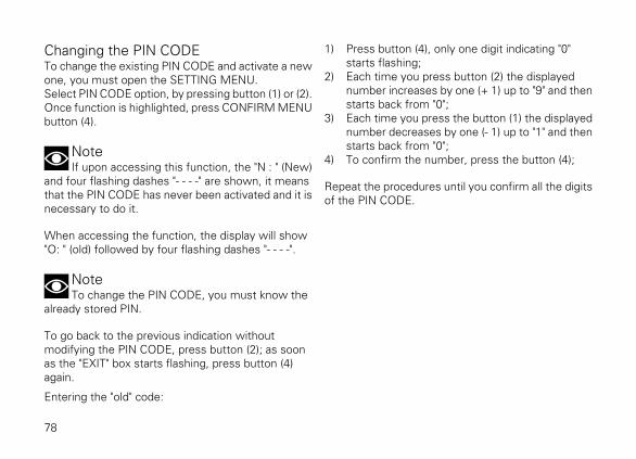
Changing the PIN CODETo change the existing PIN CODE and activate a newone, you must open the SETTING MENU.Select PIN CODE option, by pressing button (1) or (2).Once function is highlighted, press CONFIRM MENUbutton (4).
NoteIf upon accessing this function, the "N : " (New)
and four flashing dashes "- - - -" are shown, it meansthat the PIN CODE has never been activated and it isnecessary to do it.
When accessing the function, the display will show"O: " (old) followed by four flashing dashes "- - - -".
NoteTo change the PIN CODE, you must know the
already stored PIN.
To go back to the previous indication withoutmodifying the PIN CODE, press button (2); as soonas the "EXIT" box starts flashing, press button (4)again.
Entering the "old" code:
1) Press button (4), only one digit indicating "0"starts flashing;
2) Each time you press button (2) the displayednumber increases by one (+ 1) up to "9" and thenstarts back from "0";
3) Each time you press the button (1) the displayednumber decreases by one (- 1) up to "1" and thenstarts back from "0";
4) To confirm the number, press the button (4);
Repeat the procedures until you confirm all the digitsof the PIN CODE.
78

4
1
2
2
4
4
4
44
4
D
E
F
1
2
1
Fig. 43
79

After pressing button (4) to confirm the fourth and lastfigure, the 4-digit code starts flashing.Press button (4) to check the entered PIN CODE.After you press the button:
- if the PIN CODE is correct (D), the instrumentpanel shows "OK" flashing for 3 seconds,followed by "N: " (new) and four flashing dashes"- - - -" relevant to the new PIN CODE (F);
- if the PIN CODE is not correct (E), the instrumentpanel shows ERR. flashing for 3 seconds,followed by "O: " (old) and four flashing dashes "-- - -" to enter the PIN again. .
Repeat the procedures until you confirm all the digitsof the PIN CODE.
Entering the "new" code:
1) Press button (4), only one digit indicating "0"starts flashing;
2) Each time you press button (2) the displayednumber increases by one (+ 1) up to "9" and thenstarts back from "0";
3) Each time you press the button (1) the displayednumber decreases by one (- 1) up to "1" and thenstarts back from "0";
4) To confirm the number, press the button (4);
Repeat the procedures until you confirm all the digitsof the PIN CODE.
80
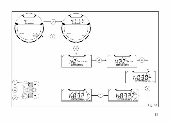
4
1
2
2
4
4 4
4
4
1
Fig. 44
81

Press button (4) to confirm the fourth and last figure:the 4-digit code starts flashing.To memorise the new setting, keep button (4)pressed for 3 seconds.If new settings have been saved (D), "MEM" will beshown, the "EXIT" option will be highlighted and itsbox will be flashing.To quit, press button (4).If settings have not been saved, the instrument panelwill highlight again the string of four dashes "- - - -" ofthe new PIN to allow the rider to try again and entera new code.
NoteYou can change your PIN CODE an unlimited
number of times.
4
4
4
2
1
4
1
2
Fig. 45
82
Setting the units of measurementThis function allows changing the units ofmeasurement of the displayed values.To manually set the units of measurement, you mustenter the SETTING MENU.Select UNITS option, by pressing button (1) or (2).Once function is highlighted, press CONFIRM MENUbutton (4).When entering this function, use buttons (1) and (2)to select the parameter for which you want to set anew unit of measurement or to restore the defaultsettings:
- SPEED;- temperature (TEMP.);- restore the default settings for units of
measurement (UNIT:DF).
To exit the menu and go back to the previous page,select "EXIT" and press button (4).
83

4
1
2
2
4
4
1
1
2
1 2
2 1
Fig. 46
84

Setting the units of measurement: Speed
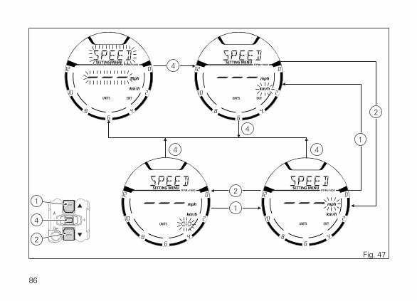
This function allows changing the unit ofmeasurement of Vehicle speed, Odometer, Trip 1,Trip 2 and Trip Fuel (when active). To gain access tothis function enter the SETTING MENU, use buttons(1) and (2) to select UNITS and press button (4). SelectSPEED option, by pressing button (1) or (2).Once SPEED function is highlighted, press CONFIRMMENU button (4). When entering the function, unitsof measurement (mph, km/h) are indicated: currentunit of measurement is flashing while the otheravailable unit is not flashing. Press buttons (1) and (2)to highlight the units of measurement one by one: inparticular, use button (1) to highlight the followingitem and button (2) to highlight the previous item.Select the required unit of measurement and thenpress the CONFIRM MENU button (4) to confirm theselected unit; then the selected unit of measurementis saved in the instrument panel and the SPEEDindication starts flashing again.
Press button (2) to make the EXIT box flash; pressbutton (4) to quit and go back to the previous window.
- Km/h: if this unit is set, the following values willhave the same units of measurement:1) TOT, TRIP 1, TRIP 2, TRIP FUEL: Km2) Motorcycle speed: Km/h
- mph: if this unit is set, the following values willhave the same units of measurement:1) TOT, TRIP 1, TRIP 2, TRIP FUEL: miles2) Motorcycle speed: mph
85
4
2
2
1
1
4
1
2
44
4
Fig. 47
86
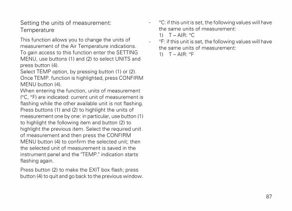
Setting the units of measurement:Temperature
This function allows you to change the units ofmeasurement of the Air Temperature indications.To gain access to this function enter the SETTINGMENU, use buttons (1) and (2) to select UNITS andpress button (4).Select TEMP option, by pressing button (1) or (2).Once TEMP. function is highlighted, press CONFIRMMENU button (4).When entering the function, units of measurement(°C, °F) are indicated: current unit of measurement isflashing while the other available unit is not flashing.Press buttons (1) and (2) to highlight the units ofmeasurement one by one: in particular, use button (1)to highlight the following item and button (2) tohighlight the previous item. Select the required unitof measurement and then press the CONFIRMMENU button (4) to confirm the selected unit; thenthe selected unit of measurement is saved in theinstrument panel and the "TEMP." indication startsflashing again.
Press button (2) to make the EXIT box flash; pressbutton (4) to quit and go back to the previous window.
- °C: if this unit is set, the following values will havethe same units of measurement:1) T – AIR: °C
- °F: if this unit is set, the following values will havethe same units of measurement:1) T – AIR: °F
87

4
2
2
1
1
4
1
2
44
4
Fig. 48
88

DEFAULT setting
This function allows setting the DEFAULT units ofmeasurement according to the vehicle version.To gain access to this function enter the SETTINGMENU, use buttons (1) and (2) to select UNITS andpress button (4). Press button (1) or (2) to make the"UNIT:DF" option start flashing and then press button(4) for 3 seconds.After 3 seconds the instrument panel shows "WAIT"for 2 seconds; then the "DF-OK" message indicatesthat the units of measurement have been restored.
4
4
Fig. 49
89
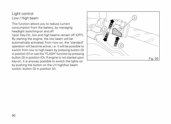
Light controlLow / High beam
This function allows you to reduce currentconsumption from the battery, by managingheadlight switching-on and off.Upon Key-On, low and high beams remain off (OFF).By starting the engine, the low beam will beautomatically activated; from now on, the "standard"operation will become active, i.e. it will be possible toswitch from low to high beam by pressing button (3)in position (V) or use the "FLASH" function by pressingbutton (3) in position (O). If engine is not started uponkey-on, it is anyway possible to switch the lights onby pushing the button on the LH high/low beamswitch: button (3) in position (V).
3
O
V
Fig. 50
90
The low beam lights are turned on the first time it ispressed; from this moment, the same button can beused to switch on (and off) the high beam light: if theengine is not started within 60 seconds, the lowbeam and high beam that were turned on will turn off.If the headlight was turned on before starting theengine with the procedure described above, theheadlight will turn off automatically when starting thevehicle and will turn ON again when the engine hasbeen completely started.
Turn indicators
Turn indicators are automatically controlled by theinstrument panel.After activating one of the two turn indicators, usercan reset them using the button (3, Fig. 50) on the leftswitch.If the turn indicator is not reset manually, theinstrument panel will automatically switch it off afterthe motorcycle has travelled 500 m (0.3 miles) fromwhen the turn indicator was activated. The counterfor the distance travelled for automatic deactivationis only activated at speeds below 80 km/h (50 mph).If the calculation of the distance for automaticdeactivation is activated and then the motorcycleexceeds a speed of 80 km/h (50 mph), the calculation
will be interrupted and will restart when the speedreturns below the indicated threshold.
91

Hazard function
The "Hazard" function turns all four turn indicators onat the same time to signal an emergency condition.The "Hazard" function is activated by taking button (3)to position (6) for 3 seconds. Activation is onlypossible when motorcycle is ON (i.e. when key isturned to "ON" while engine status does not matter).When the "Hazard" function is active, all four turnindicators blink at the same time as well as warninglights (7) on the instrument panel. The "Hazard"function can be disabled both with motorcycle on (keyset to "ON") - by taking button (3) to position (6) or bytaking button (3) to its central position - and withmotorcycle off (key set to OFF) by taking button (3)to position (6).
3
76
Fig. 51
After activating the "Hazard" function, if motorcycle isswitched OFF (key set to OFF), the function will stayactive until manually disabled by user or it will beautomatically disabled after 120 minutes (2 hours) tosave battery charge.
92

Immobilizer systemTo further improve the anti-theft protection, themotorcycle is equipped with an engine electronicblock system (IMMOBILIZER) that is automaticallyactivated every time the instrument panel is switchedoff.Inside of each key handgrip there is an electronicdevice that modulates the signal sent by a specialantenna integrated in the ignition switch uponstarting.Such modulated signal represents the "password",that changes upon every starting, that allows thecontrol unit to acknowledge the key and thus startingthe engine.
93

KeysThe motorcycle comes with 2 keys.They contain the "Immobilizer system code".Keys (B) are those for the standard use, i.e. to:
- start the engine;- open the fuel tank plug;- open the seat lock.
WarningSeparate the keys and use only one of the two
to ride the bike.
B
Fig. 52
94

OperationEvery time you turn the key from ON to OFF, theprotection system activates the engine block.If also in this case you are not able to start the engine,contact an authorised Ducati service centre.
WarningStrong impacts could damage the electronic
components inside the key. During the procedurealways use the same key. Using different keys mayprevent the system from acknowledging the code ofthe inserted key.
95

Duplicate keysWhen a customer needs spare keys, he/she shallcontact a Ducati authorised service centre and bringall keys he/she still has.The Ducati authorised service centre will program allnew and old keys.The Ducati authorised service centre may ask to thecustomer to prove to be the motorcycle owner.The codes of the keys missing during theprogramming procedure will be erased to ensure thatany lost key can not start the engine.
NoteIf the motorcycle owner changes, it is
necessary that the new owner is given all keys.
96

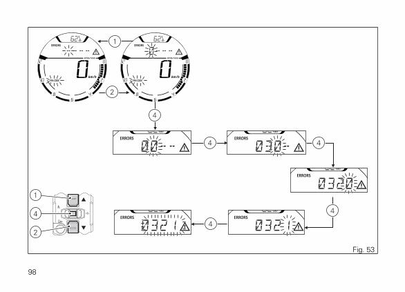
Entering PIN CODE function for overridingpurposesIn case of key acknowledgement system or keymalfunction, the instrument panel allows the user toenter his/her own PIN CODE to temporarily restoremotorcycle operation.If upon key-on an Immobilizer ERROR occurs, theinstrument panel automatically activates in MENU 1the possibility to enter the four-digit PIN CODEpreviously memorised with the relevant function inthe Setting Menu, PIN page.
Entering the code (A):
1) Press button (2) or (1), only one digit indicating "0"starts flashing;
2) Each time you press button (2) the displayednumber increases by one (+ 1) up to "9" and thenstarts back from "0";
3) Each time you press the button (1) the displayednumber decreases by one (- 1) up to "1" and thenstarts back from "0";
4) To confirm the number, press the button (4);
Repeat the procedures until you confirm all the digitsof the PIN CODE.
97
4
1
2
2
1
4
4 4
4
4
Fig. 53
98
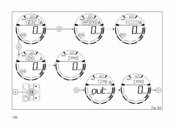
When you press button (4) to confirm the fourth andlast digit:
- if the PIN code (A) is correct, the instrumentpanel shows the message OK for 2 secondsfollowed by the "standard screen" and enablesthe vehicle to start (C);
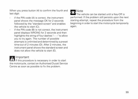
- if the PIN code (B) is not correct, the instrumentpanel displays WRONG for 2 seconds and thenhighlights the string of four dashes "- - - -" to allowyou to try again. The number of possibleattempts is unlimited and determined by a presettime-out of 2 minutes (D). After 2 minutes, theinstrument panel shows the standard screen anddoes not allow the vehicle to start (E).
ImportantIf this procedure is necessary in order to start
the motorcycle, contact an Authorised Ducati ServiceCentre as soon as possible to fix the problem.
NoteThe vehicle can be started until a Key-Off is
performed. If the problem still persists upon the nextstarting attempt, repeat the procedure from thebeginning in order to start the motorcycle temporarilyagain.
99
4
B
A
D E
Fig. 54
100
Controls
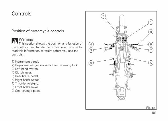
Position of motorcycle controls
WarningThis section shows the position and function of
the controls used to ride the motorcycle. Be sure toread this information carefully before you use thecontrols.
1) Instrument panel.2) Key-operated ignition switch and steering lock.3) Left-hand switch.4) Clutch lever.5) Rear brake pedal.6) Right-hand switch.7) Throttle twistgrip.8) Front brake lever.9) Gear change pedal.
2
1
8
7
5
6
3
9
4
Fig. 55
101

Key-operated ignition switch and steeringlockIt is located in front of the fuel tank and has fourpositions:
A) : enables lights and engine operation;B) : disables lights and engine operation;C) : the steering is locked;D) : parking light and steering lock.
NoteTo move the key to the last two positions, press
it down before turning it. The key can be removed inpositions (B), (C) and (D).
B A
C
D
Fig. 56
102
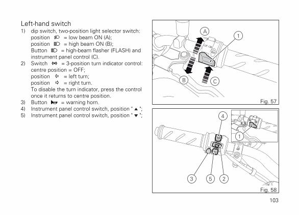
Left-hand switch1) dip switch, two-position light selector switch:
position = low beam ON (A);position = high beam ON (B);Button = high-beam flasher (FLASH) andinstrument panel control (C).
2) Switch = 3-position turn indicator control:centre position = OFF;position = left turn;position = right turn.To disable the turn indicator, press the controlonce it returns to centre position.
3) Button = warning horn.4) Instrument panel control switch, position " ";5) Instrument panel control switch, position " ";
1
B C
A
Fig. 57
253
4
1
Fig. 58
103
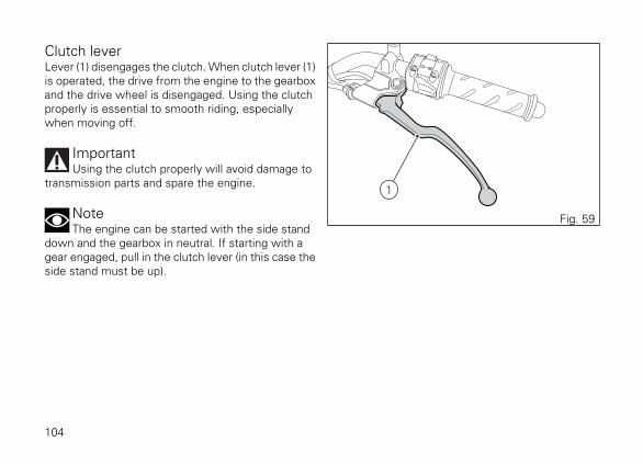
Clutch leverLever (1) disengages the clutch. When clutch lever (1)is operated, the drive from the engine to the gearboxand the drive wheel is disengaged. Using the clutchproperly is essential to smooth riding, especiallywhen moving off.
ImportantUsing the clutch properly will avoid damage to
transmission parts and spare the engine.
NoteThe engine can be started with the side stand
down and the gearbox in neutral. If starting with agear engaged, pull in the clutch lever (in this case theside stand must be up).
1
Fig. 59
104
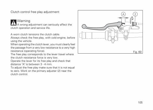
Clutch control free play adjustment
WarningA wrong adjustment can seriously affect the
clutch operation and service life.
A worn clutch tensions the clutch cable.Always check the free play, with cold engine, beforeusing the vehicle.When operating the clutch lever, you must clearly feelthe passage from a very low resistance to a very highresistance (operating force).The free play corresponds to the lever travel wherethe clutch resistance force is very low.Operate the lever for its free play and check thatdistance "A" is between 3 - 4 mm.To adjust the free play make sure that it is not equalto zero. Work on the primary adjuster (2) near theclutch control.
2A
Fig. 60
105

Adjuster (2), located on the lever, allows a maximumadjustment (Q) of 11 mm, whereas the standardadjustment (starting one) is of 5 mm. If working onsuch adjuster proves insufficient, work on thesecondary adjuster (3).
WarningIn case of a slipping clutch due to clutch wear,
adjuster (2) on the lever must NEVER be loosened,but screwed, as described above.If the clutch is still slipping, go to a Dealer or a Ducatiauthorised service centre.
2 1
Q
Fig. 61
3
Fig. 62
106
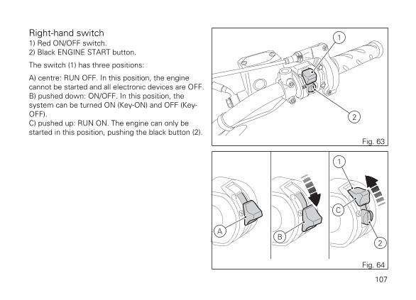
Right-hand switch1) Red ON/OFF switch.2) Black ENGINE START button.
The switch (1) has three positions:
A) centre: RUN OFF. In this position, the enginecannot be started and all electronic devices are OFF.B) pushed down: ON/OFF. In this position, thesystem can be turned ON (Key-ON) and OFF (Key-OFF).C) pushed up: RUN ON. The engine can only bestarted in this position, pushing the black button (2).
1
2
Fig. 63
AB
2
1
C
Fig. 64
107
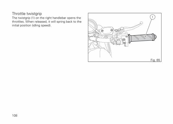
Throttle twistgripThe twistgrip (1) on the right handlebar opens thethrottles. When released, it will spring back to theinitial position (idling speed).
1
Fig. 65
108
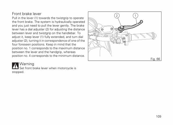
Front brake leverPull in the lever (1) towards the twistgrip to operatethe front brake. The system is hydraulically operatedand you just need to pull the lever gently. The brakelever has a dial adjuster (2) for adjusting the distancebetween lever and twistgrip on the handlebar. Toadjust it, keep lever (1) fully extended, and turn dialadjuster (2), turning it in correspondence of one of thefour foreseen positions. Keep in mind that theposition no. 1 corresponds to the maximum distancebetween the lever and the handgrip, whereasposition no. 4 corresponds to the minimum distance.
WarningSet front brake lever when motorcycle is
stopped.
12
Fig. 66
109

Rear brake pedalPress pedal down with your foot to operate the rearbrake (1).The control system is of the hydraulic type.
1
Fig. 67
110

Gear change pedalWhen released, the gear change pedal automaticallyreturns to rest position N in the centre. This isindicated by the instrument panel N light coming on.The pedal can be moved:
- down = press down the pedal to engage the 1st
gear and to shift down. The N light on theinstrument panel will go out;
- upwards= lift the pedal to engage 2nd gear andthen 3rd, 4th, 5th and 6th gears.
Each time you move the pedal you will engage thenext gear.
Fig. 68
6
5
4
3
2
1
Fig. 69
111
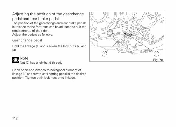
Adjusting the position of the gearchangepedal and rear brake pedalThe position of the gearchange and rear brake pedalsin relation to the footrests can be adjusted to suit therequirements of the rider.Adjust the pedals as follows:
Gear change pedal
Hold the linkage (1) and slacken the lock nuts (2) and(3).
NoteNut (2) has a left-hand thread.
Fit an open-end wrench to hexagonal element oflinkage (1) and rotate until setting pedal in the desiredposition. Tighten both lock nuts onto linkage.
2 3
1
Fig. 70
112
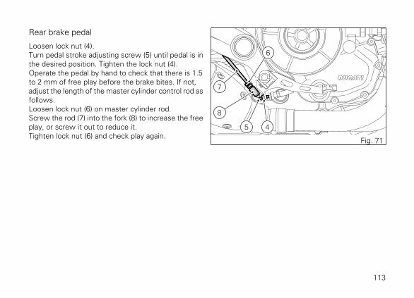
Rear brake pedal
Loosen lock nut (4).Turn pedal stroke adjusting screw (5) until pedal is inthe desired position. Tighten the lock nut (4).Operate the pedal by hand to check that there is 1.5to 2 mm of free play before the brake bites. If not,adjust the length of the master cylinder control rod asfollows.Loosen lock nut (6) on master cylinder rod.Screw the rod (7) into the fork (8) to increase the freeplay, or screw it out to reduce it.Tighten lock nut (6) and check play again.
5
8
7
6
4
Fig. 71
113

Main components anddevices
Position on the vehicle1) Tank filler plug.2) Seat lock.3) Side stand.4) Rear-view mirrors.5) Rear shock absorber adjusters.6) Catalytic converter.7) Exhaust silencer.
5 2
34
4 1
76
Fig. 72
114
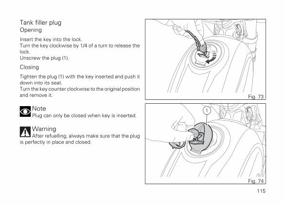
Tank filler plugOpening
Insert the key into the lock.Turn the key clockwise by 1/4 of a turn to release thelock.Unscrew the plug (1).
Closing
Tighten the plug (1) with the key inserted and push itdown into its seat.Turn the key counter clockwise to the original positionand remove it.
NotePlug can only be closed when key is inserted.
WarningAfter refuelling, always make sure that the plug
is perfectly in place and closed.
Fig. 73
1
Fig. 74
115
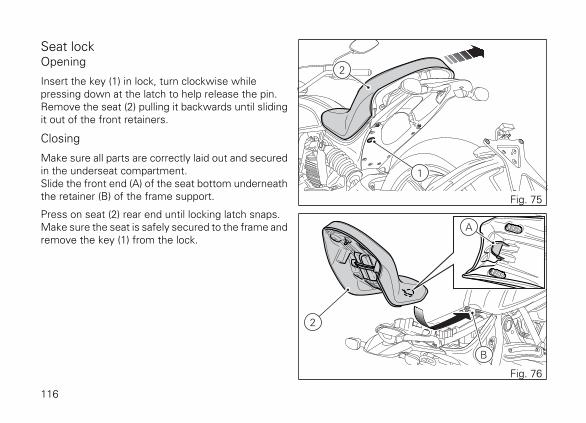
Seat lockOpening
Insert the key (1) in lock, turn clockwise whilepressing down at the latch to help release the pin.Remove the seat (2) pulling it backwards until slidingit out of the front retainers.
Closing
Make sure all parts are correctly laid out and securedin the underseat compartment.Slide the front end (A) of the seat bottom underneaththe retainer (B) of the frame support.
Press on seat (2) rear end until locking latch snaps.Make sure the seat is safely secured to the frame andremove the key (1) from the lock.
2
1
Fig. 75
2
B
A
Fig. 76
116

Side stand
ImportantPlace the motorcycle on the side stand only
when you are not going to use it for short periods oftime. Before lowering the side stand, make sure thatthe bearing surface is hard and flat.
Do not park on soft or pebbled ground or on asphaltmelt by the sun heat and similar or the motorcyclemay fall over. When parking in downhill road tracts,always park the motorcycle with its rear wheel facingdownhill.To pull down the side stand, hold the motorcyclehandlebar with both hands and push down on theside stand (1) with your foot until it is fully extended.Tilt the motorcycle until the side stand is resting onthe ground.To move the side stand to its rest position (horizontalposition), lean the motorcycle to the right while liftingthe thrust arm (1) with your foot.
1
2
Fig. 77
WarningDo not sit on the motorcycle when it is
supported on the side stand.
NoteCheck for proper operation of the stand
mechanism (two springs, one into the other) and thesafety sensor (2) at regular intervals.
117

USB connectionThe motorcycle is equipped with a USB 5Vconnection. Loads up to 1A can be connected to theUSB connection.USB connection (1) is located under the seat and isprotected by a flap: lift flap to use connection.
ImportantWhen the engine is off and key set to ON, do
not leave accessories connected to the USB socketfor a long period of time as the motorcycle batterycould run flat.
WarningThe USB connection, with no protection cap,
was not designed as a waterproof unit, you are thusrecommended not to connect any device to the USBsocket in case of rain.
1
Fig. 78
118

Adjusting the rear shock absorberThe rear shock absorber has adjusters that enable youto suit the setting to the load on the motorcycle. Thering nut (A), located in the shock absorber upper side,adjusts the external spring preload.To change spring preload, turn the ring nut (A) usingthe supplied pin wrench, and align ring nut cam withthe reference notch (B). Ring nut has five cams (1, 2,3, 4 and 5) which correspond to the available preloadsettings: turn counter clockwise (C) to INCREASEpreload, or turn clockwise (D) to DECREASE preload.Standard setting is the one for which reference notch(B) on shock absorber is aligned with ring nut thirdcam: position indicated in the figure.
A
B
D
C
Fig. 79
4
3 21
5
B
Fig. 80
119
WarningTo turn the preload adjuster ring nut use the
wrench supplied with the tool kit. Pay attention toavoid hand injuries by hitting motorcycle parts in casethe wrench tooth suddenly slips on the ring nut camwhile moving it.
WarningThe shock absorber is filled with gas under
pressure and may cause severe damage if taken apartby unskilled persons.
When carrying a passenger and luggage, set the rearshock absorber spring to proper preload to improvemotorcycle handling and keep safe clearance fromthe ground.
120
Riding the motorcycle
Running-in recommendationsMaximum rotation speed
Rotation speed for running-in period and duringstandard use (rpm):1) up to 1,000 km;2) from 1,000 km to 2,500 km.
Up to 1,000 km
During the first 1000 km, keep an eye on the revcounter. It should never exceed: 5,500÷6,000 rpm.During the first hours of riding, it is advisable to runthe engine at varying load and rpm, though still withinrecommended limit.To this end, roads with plenty of bends and evenslightly hilly areas are ideal for a most efficientrunning-in of engine, brakes and suspensions.For the first 100 km use the brakes gently. Avoidsudden or prolonged braking. This will allow thefriction material on the brake pads to bed in againstthe brake discs.
For all mechanical parts of the motorcycle to adapt toone another and above all not to adversely affect thelife of basic engine parts, it is advisable to avoid harshaccelerations and not to run the engine at high rpmfor too long, especially uphill.Furthermore, the drive chain should be inspectedfrequently. Lubricate as required.
121
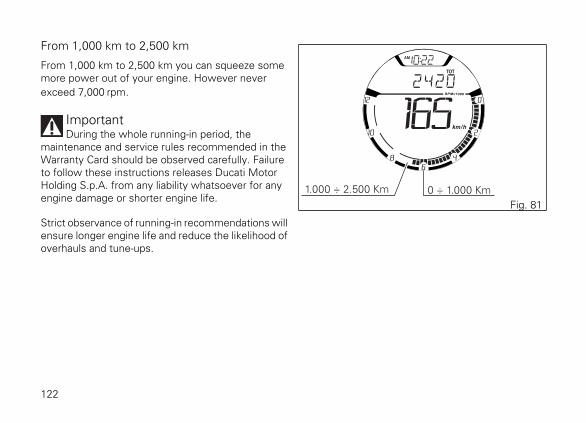
From 1,000 km to 2,500 km
From 1,000 km to 2,500 km you can squeeze somemore power out of your engine. However neverexceed 7,000 rpm.
ImportantDuring the whole running-in period, the
maintenance and service rules recommended in theWarranty Card should be observed carefully. Failureto follow these instructions releases Ducati MotorHolding S.p.A. from any liability whatsoever for anyengine damage or shorter engine life.
Strict observance of running-in recommendations willensure longer engine life and reduce the likelihood ofoverhauls and tune-ups.
1.000 ÷ 2.500 Km 0 ÷ 1.000 Km
Fig. 81
122
Pre-ride checks
WarningFailure to carry out these checks before riding,
may lead to motorcycle damage and injury to riderand passenger.
Before riding, perform a thorough check-up on yourmotorcycle as follows:
- FUEL LEVEL IN THE TANKCheck the fuel level in the tank. Fill tank if needed(page 133).
- ENGINE OIL LEVELCheck oil level in the sump through the sightglass. Top up if needed (page 156).
- BRAKE FLUIDCheck fluid level in the relevant reservoirs (page135).
- TYRE CONDITIONCheck tyre pressure and condition (page 154).
- CONTROLSWork the brake, clutch, throttle and gear changecontrols (levers, pedals and twistgrip) and checkfor proper operation.
- LIGHTS AND INDICATORSMake sure lights, indicators and horn workproperly. Replace any burnt-out bulbs (page 90).
- KEY LOCKSEnsure that tank filler plug (page 115) and seat(page 116) are properly locked.
- STANDMake sure side stand operates smoothly and isin the correct position (page 117).
123

ABS light
After Key-ON, the ABS light stays ON.When the motorcycle speed exceeds 5 km/h, thewarning light switches OFF to indicate the correctoperation of the ABS system.
WarningIn case of malfunction, do not ride the
motorcycle and contact a Ducati Dealer or authorisedService Centre.
Fig. 82
124
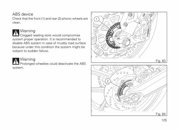
ABS deviceCheck that the front (1) and rear (2) phonic wheels areclean.
WarningClogged reading slots would compromise
system proper operation. It is recommended todisable ABS system in case of muddy road surfacebecause under this condition the system might besubject to sudden failure.
WarningProlonged wheelies could deactivate the ABS
system.
1
Fig. 83
2
Fig. 84
125
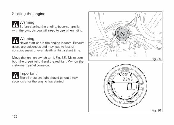
Starting the engine
WarningBefore starting the engine, become familiar
with the controls you will need to use when riding.
WarningNever start or run the engine indoors. Exhaust
gases are poisonous and may lead to loss ofconsciousness or even death within a short time.
Move the ignition switch to (1, Fig. 85). Make sureboth the green light N and the red light on theinstrument panel come on.
ImportantThe oil pressure light should go out a few
seconds after the engine has started.
1
Fig. 85
Fig. 86
126

WarningThe side stand must be fully up (in a horizontal
position) as its safety sensor prevents engine startingwhen down.
NoteIt is possible to start the engine with side stand
down and the gearbox in neutral. When starting themotorcycle with a gear engaged, pull the clutch lever(in this case the side stand must be up).
Check that the stop switch (2, Fig. 87) is positionedto (RUN), then press the starter button(3, Fig. 87).Let the motorcycle start without operating thethrottle control.
2
3
Fig. 87
NoteIf the battery is flat, system automatically
inhibits starter motor cranking operation.
ImportantDo not rev up the engine when it is cold. Allow
some time for oil to be heated and reach all pointsthat need lubricating.
127

Moving off1) Squeeze the control lever to disengage the
clutch.2) Push down on gear change lever sharply with the
tip of your foot to engage the first gear.3) Speed up the engine by turning the throttle
twistgrip while gradually releasing the clutchlever; the motorcycle will start moving off.
4) Let go of clutch lever and speed up.5) To shift up, close the throttle to slow down
engine, disengage the clutch, lift the gear changelever and let go of clutch lever.
To shift down, proceed as follows: release thetwistgrip, pull the clutch lever, shortly speed up tohelp gears synchronise, shift down (engage nextlower gear) and release the clutch.The controls should be used correctly and timely:when riding uphill do not hesitate to shift down assoon as the motorcycle tends to slow down, so youwill avoid stressing the engine and the motorcycleabnormally.
WarningAvoid harsh acceleration, as this may lead to
misfiring and transmission snatching. The clutchlever should not be held in longer than necessaryafter a gear is engaged, otherwise friction parts mayoverheat and wear out.
WarningProlonged wheelies could deactivate the ABS
system.
128

BrakingSlow down in time, shift down to use engine brakeand then brake by operating both front and rearbrakes. Pull the clutch before the motorcycle stops toavoid engine from suddenly stalling.
Anti-Lock Braking System (ABS)Using the brakes correctly under adverse conditionsis the hardest – and yet the most critical - skill tomaster for a rider. Braking is one of the most difficultand dangerous moments when riding a two wheeledmotorcycle: the possibility of falling or having anaccident during this difficult moment is statisticallyhigher than any other moment. A locked front wheelleads to loss of traction and stability, resulting in lossof control.The Anti-Lock Braking System (ABS) has beendeveloped to enable riders to use the motorcyclebraking force to the fullest possible amount inemergency braking or under poor pavement oradverse weather conditions.ABS uses hydraulics and electronics to limit pressurein the brake circuit when a special sensor mounted tothe wheel informs the electronic control unit that thewheel is about to lock up.
This avoids wheel lockup and preserves traction.Pressure is raised back up immediately and thecontrol unit keeps controlling the brake until the riskof a lockup disappears.Normally, the rider will perceive ABS operation as aharder feel or a pulsation of the brake lever and pedal.The front and rear brakes use separate controlsystems, meaning that they operate independently.Likewise, the ABS is not an integral braking systemand does not control both the front and rear brake atthe same time.If desired, the system can be deactivated from theinstrument panel, using the "ABS control unitenabling/disabling" function (seepage 64).
129

WarningWhen ABS is disabled, the motorcycle restores
the standard brake system features; using the twobrake controls separately reduces the motorcyclebraking efficiency. Never use the brake controlsharshly or suddenly as you may lock the wheels andlose control of the motorcycle. When riding in the rainor on slippery surfaces, braking will become lesseffective. Always use the brakes very gently andcarefully when riding under these conditions. Anysudden manoeuvres may lead to loss of control.When tackling long, high-gradient downhill roadtracts, shift down gears to use engine braking. Applyone brake at a time and use brakes sparingly. Keepingthe brakes applied all the time would cause thefriction material to overheat and reduce brakingpower dangerously. Underinflated tyres reducebraking efficiency, handling accuracy and stability ina bend.
130
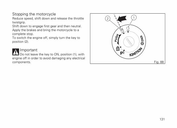
Stopping the motorcycleReduce speed, shift down and release the throttletwistgrip.Shift down to engage first gear and then neutral.Apply the brakes and bring the motorcycle to acomplete stop.To switch the engine off, simply turn the key toposition (2).
ImportantDo not leave the key to ON, position (1), with
engine off in order to avoid damaging any electricalcomponents.
2 1
Fig. 88
131
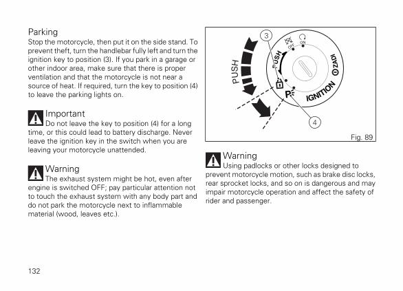
ParkingStop the motorcycle, then put it on the side stand. Toprevent theft, turn the handlebar fully left and turn theignition key to position (3). If you park in a garage orother indoor area, make sure that there is properventilation and that the motorcycle is not near asource of heat. If required, turn the key to position (4)to leave the parking lights on.
ImportantDo not leave the key to position (4) for a long
time, or this could lead to battery discharge. Neverleave the ignition key in the switch when you areleaving your motorcycle unattended.
WarningThe exhaust system might be hot, even after
engine is switched OFF; pay particular attention notto touch the exhaust system with any body part anddo not park the motorcycle next to inflammablematerial (wood, leaves etc.).
3
4
Fig. 89
WarningUsing padlocks or other locks designed to
prevent motorcycle motion, such as brake disc locks,rear sprocket locks, and so on is dangerous and mayimpair motorcycle operation and affect the safety ofrider and passenger.
132

RefuellingNever overfill the tank when refuelling. Fuel shouldnever be touching the rim of filler recess (1).
WarningUse fuel with low lead content and an original
octane number of at least 95.
WarningThe motorcycle is only compatible with fuel
having a maximum content of ethanol of 10% (E10).Using fuel with ethanol content over 10% isforbidden. Using it could result in severe damage ofthe engine and motorcycle components. Using fuelwith ethanol content over 10% will make thewarranty null and void.
1
Fig. 90
Max level
Fig. 91
133
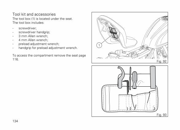
Tool kit and accessoriesThe tool box (1) is located under the seat.The tool box includes:
- screwdriver;- screwdriver handgrip;- 3 mm Allen wrench;- 4 mm Allen wrench;- preload adjustment wrench;- handgrip for preload adjustment wrench.
To access the compartment remove the seat page116.
1
Fig. 92
Fig. 93
134
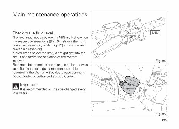
Main maintenance operations
Check brake fluid levelThe level must not go below the MIN mark shown onthe respective reservoirs ((Fig. 94) shows the frontbrake fluid reservoir, while (Fig. 95) shows the rearbrake fluid reservoir).If level drops below the limit, air might get into thecircuit and affect the operation of the systeminvolved.Fluid must be topped up and changed at the intervalsspecified in the scheduled maintenance tablereported in the Warranty Booklet; please contact aDucati Dealer or authorised Service Centre.
ImportantIt is recommended all lines be changed every
four years.
MIN
Fig. 94
MAX
Fig. 95
135

Brake system
If you find exceeding clearance on brake lever orpedal and brake pads are still in good condition,contact your Ducati Dealer or authorised ServiceCentre to have the system inspected and any airdrained out of the circuit.
WarningBrake fluid can damage paintwork and plastic
parts, so avoid contact.Hydraulic fluid is corrosive; it may cause damage andlead to severe injuries. Never mix fluids of differentqualities. Check seals for proper sealing.
Changing the air filter
ImportantHave the air filter maintenance performed at a
Ducati Dealer or Authorised Service Centre.
136
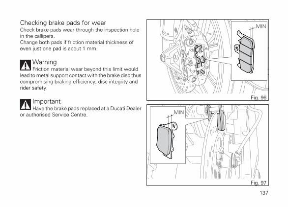
Checking brake pads for wearCheck brake pads wear through the inspection holein the callipers.Change both pads if friction material thickness ofeven just one pad is about 1 mm.
WarningFriction material wear beyond this limit would
lead to metal support contact with the brake disc thuscompromising braking efficiency, disc integrity andrider safety.
ImportantHave the brake pads replaced at a Ducati Dealer
or authorised Service Centre.
MIN
Fig. 96
MIN
Fig. 97
137

Charging the battery
WarningHave the battery removed at a Ducati Dealer or
authorised Service Centre.
To reach the battery, remove the seat page 116 andremove battery cover (A), after disengaging rubberband (C) and loosening screw (D). Loosen the screws(1), remove the positive cable (2) and (ABS) positivecable (3) from the positive terminal and the negativecable (4) from the negative terminal always startingfrom the negative one (-) and remove the battery bysliding it out of its housing.
WarningThe battery gives off explosive gases; never
cause sparks or allow naked flames and cigarettesnear the battery. When charging the battery, ensurethat the working area is properly ventilated.
A
D
C
Fig. 98
1
4
1
2
3
Fig. 99
138

Charge the battery in a ventilated room.Connect the battery charger leads to the batteryterminals: the red one to the positive terminal (+), theblack one to the negative terminal (-).
ImportantMake sure the charger is OFF when you
connect the battery to it, or you might get sparks atthe battery terminals that could ignite the gasesinside the cells. Always connect the red positive (+)terminal first.
Grease the screws (1, Fig. 99).Refit the battery, connect the positive cable(2, Fig. 99) and ABS positive cable (3, Fig. 99) to thepositive terminal, and the negative cable (4, Fig. 99)to the negative terminal of the battery, alwaysstarting from the positive one (+), and start thescrews (1, Fig. 99). Refit the battery cover(A, Fig. 98), engage rubber band (C, Fig. 98) andtighten screw (D, Fig. 98) to 5 Nm ± 10%.
WarningKeep the battery out of the reach of children.
Charge the battery at 0.9 A for 5÷10 hours.
If the motorcycle must be jump-started in anemergency with an external starting device, it ispossible to connect the starting device to the batterywithout removing it from the vehicle. Connect theexternal starting device positive pole to the batterypositive pole and the external starting device negativepole to the battery negative pole.
WarningWhen connecting the external starting device to
the poles of the vehicle battery, pay utmost attentionnot to touch any other metal parts on the vehicle.
139

Charging and maintenance of the battery duringwinter storage
Your motorcycle is equipped with a connector (1),located under the seat, to which you can connect aspecial battery charger (2) (Battery maintenance kitpart no. 69924601A - various countries; Batterymaintainer kit part no. 69924601AX - for Japan, Chinaand Australia only) available from our sales network.
NoteThe electric system of this model is designed so
as to ensure there is a very low power drain when themotorcycle is OFF. Nevertheless, the batteryfeatures a certain self-discharge rate that is normaland depends on ambient conditions as well as on"non-use" time.
1
Fig. 100
2
Fig. 101
140
ImportantIf battery is not kept at a minimum charge level
by a suitable battery charge maintainer, sulphationmay occur and this is an irreversible phenomenoncausing decreasing battery performance.
NoteWhen the motorcycle is left unused
(approximately for more than 30 days) werecommend owners to use the Ducati battery chargemaintainer (Battery maintenance kit part no.69924601A - various countries; Battery maintainer kitpart no. 69924601AX - for Japan, China and Australiaonly) since its electronics monitors the batteryvoltage and features a maximum charge current of1.5 Ah. Connect the maintainer to the diagnosticssocket located in the rear side of the motorcycle.
NoteUsing charge maintainers not approved by
Ducati could damage the electric system; motorcyclewarranty does not cover the battery if damaged dueto failure to comply with the above indications, sinceit is considered as wrong maintenance.
141

Lubricating cables and jointsIt is necessary to periodically check the throttlecontrol cable and cold start cable external sheath forwear. Their external plastic sheath should be free ofcracking or flattening. Work the controls to make surethe cable slides smoothly inside the sheath: if youfeel any friction or catching, have the cable replacedby a Ducati Dealer or Authorised Service Centre.For trouble-free operation, periodically lubricate theends of all Bowden cables with SHELL AdvanceGrease or Retinax LX2.As far as the throttle cable is concerned, it isrecommended to undo the two screws (1) and openthe control, then grease the cable end and the pulley.
WarningCarefully close the control after engaging the
cable in the pulley.
1
1
Fig. 102
Refit the cover and tighten the screws (1) to a torqueof 1.8 Nm.To ensure trouble-free operation of the side standjoint, thoroughly clean it and then use SHELL AlvaniaR3 grease to lubricate all friction points.
142
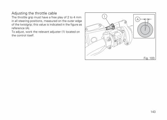
Adjusting the throttle cableThe throttle grip must have a free play of 2 to 4 mmin all steering positions, measured on the outer edgeof the twistgrip; this value is indicated in the figure asreference (A).To adjust, work the relevant adjuster (1) located onthe control itself.
1A
Fig. 103
143

Checking drive chain tension
ImportantHave chain tension adjusted by a Ducati Dealer
or authorised Service Centre.
Make the rear wheel turn until you find the positionwhere chain is tightest. Set the motorcycle on theside stand. With just a finger, push down the chain atthe point of measurement and release. Measure thedistance (A) between the centre of the chain pins andthe aluminium section of the swinging arm. It mustbe: A = 27 ÷ 29 mm.
ImportantIf drive chain is too tight or slack, adjust tension
so as to bring values back to the specified range.
= =
A
Fig. 104
144

WarningCorrect tightening of swinging arm screws (1) is
critical to rider and passenger safety.
ImportantImproper chain tension will lead to early wear of
transmission parts.
Check the correspondence of the positioning markson both sides of the swinging arm to ensure a perfectwheel alignment. Grease the wheel shaft nut thread(2) with SHELL Retinax HDX2 and tighten it to atorque of 145 Nm. Grease the adjuster screws (1)thread with SHELL Alvania R3 and tighten them to atorque of 10 Nm.
1 2
Fig. 105
145
Lubricating the drive chainThe chain fitted on your motorcycle has O-rings thatkeep dirt out of and lubricant inside the sliding parts.The seals might be irreparably damaged if the chainis cleaned using any solvent other than those specificfor O-ring chains or washed using steam or watercleaners.After cleaning, blow the chain dry with compressedair or wipe it with an absorbent material, thenlubricate each link with SHELL Advance Chain orAdvance Teflon Chain.
ImportantUsing non-specific lubricants may cause severe
damage to the chain and the front and rear sprockets.
146
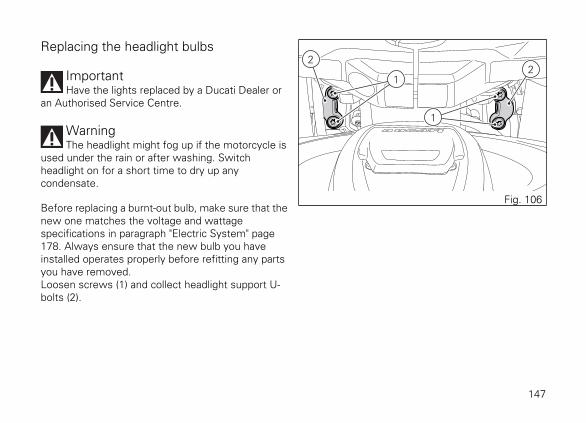
Replacing the headlight bulbs
ImportantHave the lights replaced by a Ducati Dealer or
an Authorised Service Centre.
WarningThe headlight might fog up if the motorcycle is
used under the rain or after washing. Switchheadlight on for a short time to dry up anycondensate.
Before replacing a burnt-out bulb, make sure that thenew one matches the voltage and wattagespecifications in paragraph "Electric System" page178. Always ensure that the new bulb you haveinstalled operates properly before refitting any partsyou have removed.Loosen screws (1) and collect headlight support U-bolts (2).
1
1
22
Fig. 106
147
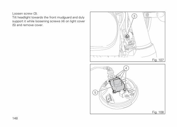
Loosen screw (3).Tilt headlight towards the front mudguard and dulysupport it while loosening screws (4) on light cover(5) and remove cover.
3
Fig. 107
4
5
Fig. 108
148

Disconnect the connector (6).Release the clip (7).The bulb (8) has a bayonet joint: press and twistcounter clockwise to remove it. Remove the bulb,then fit the new one by pressing and turningclockwise until it clicks into its seat.
NoteBe careful to hold the new bulb at the base only.
Never touch the transparent body with your fingersor it will blacken resulting in reduced bulb brilliancy.
To reassemble, refit any previously removed partsfollowing the removal procedure in reverse order andtighten screws (1, Fig. 106) to 5 Nm.
6
Fig. 109
8
8 7
Fig. 110
149

Changing the turn indicator bulbsTo change the front/rear turn indicator bulbs, loosenthe screw (1) and remove the lens (2).
2 1
Fig. 111
2
1
Fig. 112
150

Aligning the headlight
NoteHeadlight features two adjusters, one for the
RH beam and one for the LH beam.
Check correct headlight aiming. Position themotorcycle 10 metres from a wall or a screen, themotorcycle must be perfectly upright with the tiresinflated to the correct pressure and with a riderseated, perfectly perpendicular to the longitudinalaxis. On the wall or surface, draw a horizontal line atthe same height from the ground as the centre of theheadlight and a vertical line aligned with thelongitudinal axis of the motorcycle. If possible,perform this check in dim light. Switch on the lowbeam and adjust right and left beams. The height ofthe upper limit between the dark area and the lit areamust not be more than 9/10 of the height from theground of the headlight centre.
10 m
9
10x
x
Fig. 113
NoteThis is the procedure specified by Italian
regulations for checking the maximum height of thelight beam. Please adapt said procedure to theprovisions in force in your own country.
151
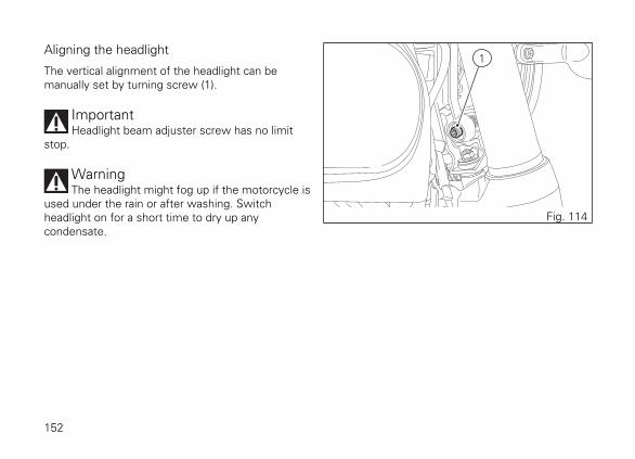
Aligning the headlight
The vertical alignment of the headlight can bemanually set by turning screw (1).
ImportantHeadlight beam adjuster screw has no limit
stop.
WarningThe headlight might fog up if the motorcycle is
used under the rain or after washing. Switchheadlight on for a short time to dry up anycondensate.
1
Fig. 114
152
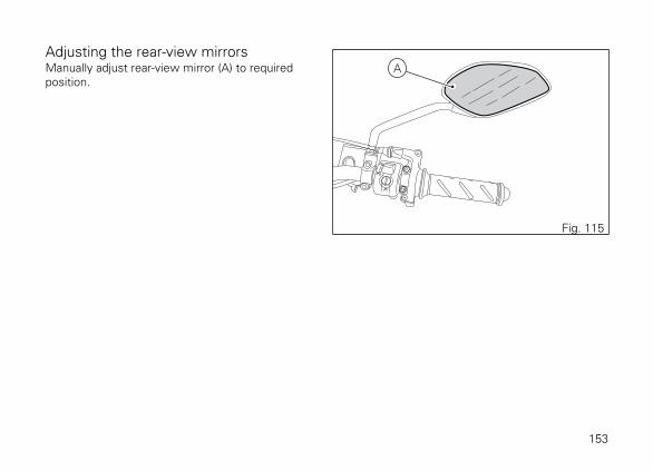
Adjusting the rear-view mirrorsManually adjust rear-view mirror (A) to requiredposition.
A
Fig. 115
153
Tubeless tyresFront tyre pressure:2.50 bar (rider only) - 2.50 bar (full load).Rear tyre pressure:2.50 bar (rider only) - 2.90 bar (full load).As tyre pressure is affected by ambient temperatureand altitude variations, you are advised to check andadjust it whenever you are riding in areas whereample variations in temperature or altitude occur.
ImportantCheck and set tyre pressure when tyres are
cold. To avoid front wheel rim distortion, when ridingon bumpy roads, increase tyre pressure by 0.2 ÷ 0.3bar.
Tyre repair or change (Tubeless tyres)
In the event of a tiny puncture, tubeless tyres will takea long time to deflate, as they tend to keep air inside.If you find low pressure on one tyre, check the tyrefor punctures.
WarningPunctured tyres must be replaced. Replace
tyres with recommended standard tyres only. Besure to tighten the valve caps securely to avoid leakswhen riding. Never use tube type tyres. Failure toheed this warning may lead to sudden tyre burstingand to serious danger to rider and passenger.
After replacing a tyre, the wheel must be balanced.
WarningDo not remove or shift the wheel balancing
weights.
NoteHave the tyres replaced at a Ducati Dealer or
authorised Service Centre. Correct removal andinstallation of the wheels is essential. Some parts ofthe ABS (such as sensors and phonic wheels) aremounted to the wheels and require specificadjustment.
Minimum tread depth
154
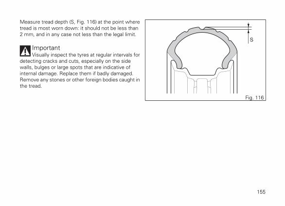
Measure tread depth (S, Fig. 116) at the point wheretread is most worn down: it should not be less than2 mm, and in any case not less than the legal limit.
ImportantVisually inspect the tyres at regular intervals for
detecting cracks and cuts, especially on the sidewalls, bulges or large spots that are indicative ofinternal damage. Replace them if badly damaged.Remove any stones or other foreign bodies caught inthe tread.
S
Fig. 116
155

Check engine oil levelEngine oil level can be checked through the sightglass (1) located onto clutch cover. Oil level must bechecked with the motorcycle perfectly upright andthe engine cold. Oil level should be between themarks on the sight glass. If the level is low, top upwith SHELL Advance 4T Ultra engine oil. Remove theoil filler cap (2) and top up until the oil reaches therequired level. Refit the plug.
ImportantEngine oil and oil filters must be changed by a
Ducati Dealer or authorised Service Centre at theintervals specified in the scheduled maintenancechart reported in the Warranty Card.
1
2
Fig. 117
156

Viscosity
SAE 15W-50The other viscosity degrees indicated in the table canbe used if the local average temperature is within thelimits specified for that oil viscosity.
–10
Unig
rade
Multig
rade
0 10 20 30 40 C
40
20W–40 20W–50
15W–40 15W–50
10W–40
10W–30
10W
20W
20
30
Fig. 118
157

Cleaning and replacing the spark plugsSpark plugs are essential to smooth engine runningand should be checked at regular intervals.Have the spark plug replaced by a Ducati Dealer or anauthorised Service Centre.
Fig. 119
158

Cleaning the motorcycleTo preserve the finish of metal parts and paintwork,wash and clean your motorcycle at regular intervals,anyway according to road conditions. Use specificproducts only. Prefer biodegradable products. Avoidaggressive detergents or solvents.Use only water and neutral soap to clean the Plexiglasand the seat.Periodically clean by hand all aluminium components.Use special detergents, suitable for aluminium parts.Do NOT use abrasive detergents or caustic soda.
NoteDo not use sponges with abrasive parts or steel
wool: only use soft cloths.
However, the warranty does not apply to motorcycleswhenever poor maintenance status is ascertained.
ImportantDo not wash your motorcycle right after use.
When the motorcycle is still hot, water drops willevaporate faster and spot hot surfaces.Never clean the motorcycle using hot or high-pressure water jets.Cleaning the motorcycle with a high pressure waterjet may lead to seizure or serious faults in forks,wheel hubs, electric system, headlight (fogging), forkseals, air inlets or exhaust silencers, with consequentloss of compliance with the safety requirements.Clean off stubborn dirt or exceeding grease fromengine parts using a degreasing agent. Be sure toavoid contact with drive parts (chain, sprockets, etc.).
Rinse with warm water and dry all surfaces withchamois leather.
WarningBraking performance may be impaired
immediately after washing the motorcycle. Nevergrease or lubricate the brake discs to avoid losingbraking power. Clean the discs with an oil-freesolvent.
159
WarningThe headlight might fog up due to washing, rain
or moisture. Switch headlight on for a short time tohelp and dry up any condensate.
Carefully clean the phonic wheels of the ABS in orderto ensure system efficiency. Do not use aggressiveproducts in order to avoid damaging the phonicwheels and the sensors.
160
Storing the motorcycleIf the motorcycle is to be left unridden over longperiods, it is advisable to carry out the followingoperations before storing it away:
- clean the motorcycle;- empty the fuel tank;- pour a few drops of engine oil into the cylinders
through the spark plug seats, then crank theengine by hand a few times so a protective filmof oil will spread on cylinder inner walls;
- place the motorcycle on a service stand;- disconnect and remove the battery.
Battery should be checked and charged (or replaced,as required) whenever the motorcycle has been leftunridden for over a month.Protect the motorcycle with a suitable canvas. Thiswill protect paintwork and let condensate breatheout.The canvas is available from Ducati Performance.
Important notesSome countries, such as France, Germany, GreatBritain, Switzerland, etc. have compulsory emissionand noise standards that include mandatoryinspections at regular intervals.
Periodically carry out the required checks and renewparts as necessary, using Ducati original spare parts,in compliance with the regulations in the countryconcerned.
161
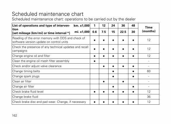
Scheduled maintenance chartScheduled maintenance chart: operations to be carried out by the dealer
List of operations and type of interven-tion[set mileage (km/mi) or time interval *]
km. x1,000 1 12 24 36 48Time
(months)mi. x1,000 0.6 7.5 15 22.5 30
Reading of the error memory with DDS and check ofsoftware version update on control units 12
Check the presence of any technical updates and recallcampaigns 12
Change engine oil and filter 12
Clean the engine oil mesh filter assembly -
Check and/or adjust valve clearance -
Change timing belts 60
Change spark plugs -
Clean air filter -
Change air filter -
Check brake fluid level 12
Change brake fluid 36
Check brake disc and pad wear. Change, if necessary 12
162
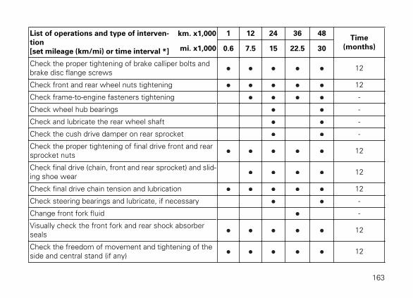
List of operations and type of interven-tion[set mileage (km/mi) or time interval *]
km. x1,000 1 12 24 36 48Time
(months)mi. x1,000 0.6 7.5 15 22.5 30
Check the proper tightening of brake calliper bolts andbrake disc flange screws 12
Check front and rear wheel nuts tightening 12
Check frame-to-engine fasteners tightening -
Check wheel hub bearings -
Check and lubricate the rear wheel shaft -
Check the cush drive damper on rear sprocket -
Check the proper tightening of final drive front and rearsprocket nuts 12
Check final drive (chain, front and rear sprocket) and slid-ing shoe wear 12
Check final drive chain tension and lubrication 12
Check steering bearings and lubricate, if necessary -
Change front fork fluid -
Visually check the front fork and rear shock absorberseals 12
Check the freedom of movement and tightening of theside and central stand (if any) 12
163
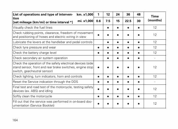
List of operations and type of interven-tion[set mileage (km/mi) or time interval *]
km. x1,000 1 12 24 36 48Time
(months)mi. x1,000 0.6 7.5 15 22.5 30
Visually check the fuel lines 12
Check rubbing points, clearance, freedom of movementand positioning of hoses and electric wiring in view 12
Lubricate the levers at the handlebar and pedal controls 12
Check tyre pressure and wear 12
Check the battery charge level 12
Check secondary air system operation -
Check the operation of the safety electrical devices (sidestand sensor, front and rear brake switches, engine stopswitch, gear/neutral sensor)
12
Check lighting, turn indicators, horn and controls 12
Reset the Service indication through the DDS -
Final test and road test of the motorcycle, testing safetydevices (ex. ABS) and idling 12
Softly clean the motorcycle 12
Fill out that the service was performed in on-board doc-umentation (Service Booklet) 12
164
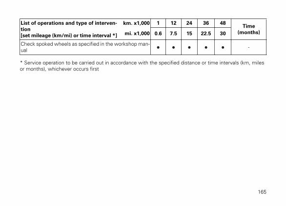
List of operations and type of interven-tion[set mileage (km/mi) or time interval *]
km. x1,000 1 12 24 36 48Time
(months)mi. x1,000 0.6 7.5 15 22.5 30
Check spoked wheels as specified in the workshop man-ual -
* Service operation to be carried out in accordance with the specified distance or time intervals (km, milesor months), whichever occurs first
165

Scheduled maintenance chart: operations to be carried out by the Customer
List of operations and type of intervention [set mileage (km/mi) or timeinterval *]
km. x1,000 1
mi x1,000 0.6
Months 6
Check engine oil level
Check brake fluid level
Check tyre pressure and wear
Check final drive chain tension and lubrication
Check brake pads. If necessary, contact your dealer to replace pads
* Service operation to be carried out in accordance with the specified distance or time intervals (km, milesor months), whichever occurs first
166

Technical data
WeightsOverall weight (in running order with 90% of fuel -93/93/EC):186 kg (ICON);192 kg (URBAN ENDURO);186 kg (FULL THROTTLE);186,5 kg (CLASSIC);Overall weight (without fluids and battery):170 kg (ICON);176 kg (URBAN ENDURO);170 kg (FULL THROTTLE);176,5 kg (CLASSIC);Maximum allowed weight (carrying full load):365 kg
WarningFailure to observe weight limits could result in
poor handling and impair the performance of yourmotorcycle, and you may lose control of themotorcycle.
167

Dimensions
855±20 mm
11
50
±2
0 m
m
11
04
±2
0 m
m
1450±20 mm
170±20 mm300±20 mm
2100±20 mm / 2140±20mm
46
0±
20
mm
79
0±
20
mm
C D
DBD
C
D
BA
A
B
D
C
Fig. 120
168
Whenever values are indicated with a letter, please refer to the following list:A) Scrambler ICONB) Scrambler URBAN ENDUROC) Scrambler FULL THROTTLED) Scrambler CLASSIC
169
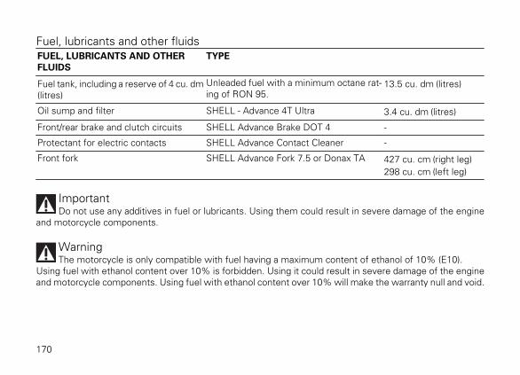
Fuel, lubricants and other fluidsFUEL, LUBRICANTS AND OTHERFLUIDS
TYPE
Fuel tank, including a reserve of 4 cu. dm(litres)
Unleaded fuel with a minimum octane rat-ing of RON 95.
13.5 cu. dm (litres)
Oil sump and filter SHELL - Advance 4T Ultra 3.4 cu. dm (litres)
Front/rear brake and clutch circuits SHELL Advance Brake DOT 4 -
Protectant for electric contacts SHELL Advance Contact Cleaner -
Front fork SHELL Advance Fork 7.5 or Donax TA 427 cu. cm (right leg)298 cu. cm (left leg)
ImportantDo not use any additives in fuel or lubricants. Using them could result in severe damage of the engine
and motorcycle components.
WarningThe motorcycle is only compatible with fuel having a maximum content of ethanol of 10% (E10).
Using fuel with ethanol content over 10% is forbidden. Using it could result in severe damage of the engineand motorcycle components. Using fuel with ethanol content over 10% will make the warranty null and void.
170

EngineLongitudinal 90º "L" twin cylinder, four-stroke.Bore, mm: 88Stroke, mm: 66Total displacement, cu. cm: 803Compression ratio: 11±0.5:1Max. power at crankshaft (95/1/EC):55 kW - 74 HP at 8,250 rpmMax. torque at crankshaft (95/1/EC):68 Nm - 6.9 Kgm at 5,750 rpm.Maximum rpm:9,200.
ImportantDo not exceed the specified rpm limits in any
running conditions.
171

Timing systemDESMODROMIC system with two valves percylinder controlled by four rocker arms (two openingand two closing ones) and one overhead camshaft.This system is driven by the crankshaft through spurgears, belt rollers and toothed belts.Desmodromic timing system
1) Opening (or upper) rocker arm;2) Upper rocker arm shim;3) Split rings;4) Closing (or lower) rocker arm shim;5) Return spring for lower rocker arm;6) Closing (or lower) rocker arm;7) Camshaft;8) Valve.
1
2
3
4
6
5
78
Fig. 121
172

Performance dataMaximum speed in any gear should be reached onlyafter a correct running-in period with the motorcycleproperly serviced at the recommended intervals.
ImportantFailure to follow these instructions releases
Ducati Motor Holding S.p.A. from any liabilitywhatsoever for any engine damage or shorter enginelife.
Spark plugsMake: NGKType: DCPR8E
Fuel systemSIEMENS indirect electronic injection.Injectors per cylinder: 1Firing points per injector: 8Fuel supply: 95-98 RON.
WarningThe motorcycle is only compatible with fuel
having a maximum content of ethanol of 10% (E10).Using fuel with ethanol content over 10% isforbidden. Using it could result in severe damage ofthe engine and motorcycle components. Using fuelwith ethanol content over 10% will make thewarranty null and void.
BrakesSeparate-action anti-lock braking system operated byhall-type sensors mounted to each wheel with phonicwheel detection: ABS can be disabled.
FRONTSemi-floating drilled disc.Braking material: steel.Carrier material: steel.Disc diameter: 330 mm.
173

Hydraulically operated by a control lever on handlebarright-hand side.Brake calliper make: BREMBO.Type: M4.3 pistons.Friction material: TT 2182 FF.Master cylinder type: PS 13/22.
REARWith fixed drilled steel disc.Disc diameter: 245 mm.Hydraulically operated by a pedal on RH side.Make: BREMBOType: PF32.Friction material: FERIT I/D 450 FF.Master cylinder type: PS 11.
WarningThe brake fluid used in the brake system is
corrosive.In the event of accidental contact with eyes or skin,wash the affected area with abundant running water.
TransmissionWet clutch controlled by the lever on left-hand sideof the handlebar.Drive is transmitted from engine to gearbox primaryshaft via spur gears.Front chain sprocket/clutch gearwheel ratio: 33/616-speed gearbox with constant mesh gears and gearchange pedal on left side of motorcycle.
Gearbox output sprocket/rear chain sprocket ratio:15/39Total gear ratios:1st gear 13/322nd gear 18/303rd gear 21/284th gear 23/265th gear 22/226th gear 26/24
Drive chain from gearbox to rear wheel.Make: DIDType: 520 VFSize: 5/8" x 1/4"Links: 104
174

ImportantThe above gear ratios are the homologated ones
and under no circumstances must they be modified.
WarningIf the rear sprocket needs replacing, contact a
Ducati Dealer or authorised Service Centre.If improperly replaced, this component couldseriously endanger your safety, as well as thepassenger one, and cause irreparable damage to yourmotorcycle.
FrameHigh-strength tubular steel trellis frame.Steering angle (per side): 35°Steering head angle: 24°Trail in mm: 112
WheelsTen-spoke light alloy wheel rims (ICON, FULLTHROTTLE).Spoked wheel rims (URBAN ENDURO, CLASSIC)
FrontSize: MT 3.00 x 18"
RearSize: MT 5.50 x 17"
Both wheel shafts can be removed.
TyresFront"Tubeless", radial tyre.Size: 110/80-R18 MC 58H
Rear"Tubeless", radial tyre.Size: 180/55-R17 MC73H
Suspensions
175
Front
Non-adjustable hydraulic upside-down fork.Stanchion diameter:51 mm.Wheel travel: 150 mm.
Rear
Progressive. The shock absorber is adjustable forspring preload. At the bottom pivot point it isconnected to a die-cast aluminium single-sidedswinging arm. The whole system gives themotorcycle excellent stability.Suspension travel: 61 mm.Rear wheel travel: 150 mm.
Exhaust systemSingle silencer with stainless steel expansion andinsulation chambers.Catalytic converter built into the silencer and twolambda sensors on the exhaust pipes at the headoutput.
Available coloursScrambler ICON‘62 YellowPrimer code DS20052 (LECHLER);
Varnish code MC060035 (LECHLER);Charcoal black frame AKZO NOBEL code MY/2/9611AVMatt Black wheel rims PEHADUR EINBRENN-LACKVPCH03352 (Peter Lacke)
Ducati RedPrimer code 2920007 (LECHLER);Varnish code LMC06017 (LECHLER);Charcoal black frame AKZO NOBEL code MY/2/9611AVMatt Black wheel rims PEHADUR EINBRENN-LACKVPCH03352 (Peter Lacke)
Scrambler URBAN ENDUROWild GreenPrimer code DS20054 (LECHLER);Varnish code MC060013 (LECHLER);Charcoal black frame AKZO NOBEL code MY/2/9611AVMatt Black wheel rims PEHADUR EINBRENN-LACKVPCH03352 (Peter Lacke)
Scrambler FULL THROTTLEDeep BlackPrimer code 881I0748 (PALINAL);Base coat code 929.R223 (PALINAL);Clear coat code 923I.2176 (PALINAL);
176
Charcoal black frame AKZO NOBEL code MY/2/9611AVMatt Black wheel rims PEHADUR EINBRENN-LACKVPCH03352 (Peter Lacke)
Scrambler CLASSICOrange SunshinePrimer code DS20052 (LECHLER);Base coat code 2909041 (LECHLER);Clear coat code 96230 (LECHLER);Charcoal black frame AKZO NOBEL code MY/2/9611AVMatt Black wheel rims PEHADUR EINBRENN-LACKVPCH03352 (Peter Lacke)
177
Electric systemBasic electric items are:Headlight:low/high beam: H4 bulb (12V – 60/55W);parking light: no. 1 LED (3.1W — 13.5V)Electrical controls on handlebars.Turn indicators:front: 12V RY10W bulb;rear: 12 VRY10W bulb.Horn.Stop light switches.Battery, 12V-10 Ah, dry.GENERATOR 14V-490W.ELECTRONIC RECTIFIER, protected by a 30A fuselocated next to fuse box (C, Fig. 123).Starter motor: 12V-0.7 kW.Tail light:parking light: 2 LEDs (3.24W-12V);stop light: 6 LEDs (7.9W-12V).Number plate light:lamp: 3 LEDs (0.67W-13.5V).
NoteFor bulb replacement instructions, please see
the paragraph "Replacing the high and low beambulbs".
Fuses
There are seven fuses that protect the electriccomponents, located inside the fuse box, and one onthe solenoid starter. The fuse box includes two sparefuses.Refer to the table below to identify the circuitsprotected by the various fuses and their ratings.
178
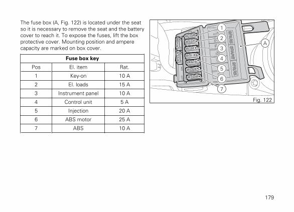
The fuse box (A, Fig. 122) is located under the seatso it is necessary to remove the seat and the batterycover to reach it. To expose the fuses, lift the boxprotective cover. Mounting position and amperecapacity are marked on box cover.
Fuse box key
Pos El. item Rat.
1 Key-on 10 A
2 El. loads 15 A
3 Instrument panel 10 A
4 Control unit 5 A
5 Injection 20 A
6 ABS motor 25 A
7 ABS 10 A
1
A2
3
4
5
6
7
Fig. 122
179

The main fuse (C) is positioned on the solenoid starter(D). Remove the fuse cap (E) to reach it. A blown fusecan be identified by breakage of the inner filament (F).
ImportantSwitch the ignition key to OFF before replacing
the fuse to avoid possible short-circuits.
WarningNever use a fuse with a rating other than
specified. Failure to observe this rule may damagethe electric system or even cause fire.
D
EC
Fig. 123
F F
Fig. 124
180
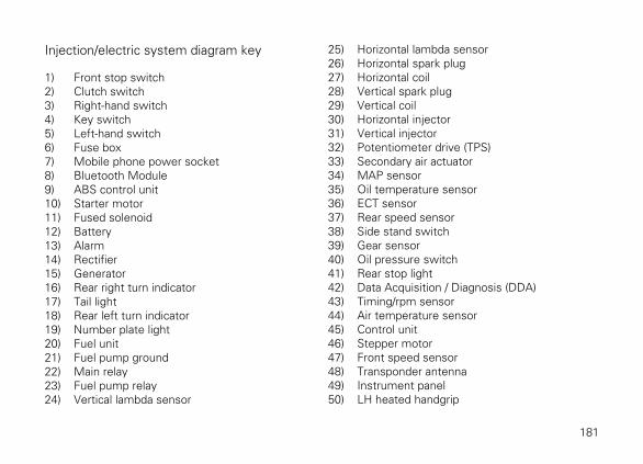
Injection/electric system diagram key
1) Front stop switch2) Clutch switch3) Right-hand switch4) Key switch5) Left-hand switch6) Fuse box7) Mobile phone power socket8) Bluetooth Module9) ABS control unit10) Starter motor11) Fused solenoid12) Battery13) Alarm14) Rectifier15) Generator16) Rear right turn indicator17) Tail light18) Rear left turn indicator19) Number plate light20) Fuel unit21) Fuel pump ground22) Main relay23) Fuel pump relay24) Vertical lambda sensor
25) Horizontal lambda sensor26) Horizontal spark plug27) Horizontal coil28) Vertical spark plug29) Vertical coil30) Horizontal injector31) Vertical injector32) Potentiometer drive (TPS)33) Secondary air actuator34) MAP sensor35) Oil temperature sensor36) ECT sensor37) Rear speed sensor38) Side stand switch39) Gear sensor40) Oil pressure switch41) Rear stop light42) Data Acquisition / Diagnosis (DDA)43) Timing/rpm sensor44) Air temperature sensor45) Control unit46) Stepper motor47) Front speed sensor48) Transponder antenna49) Instrument panel50) LH heated handgrip
181
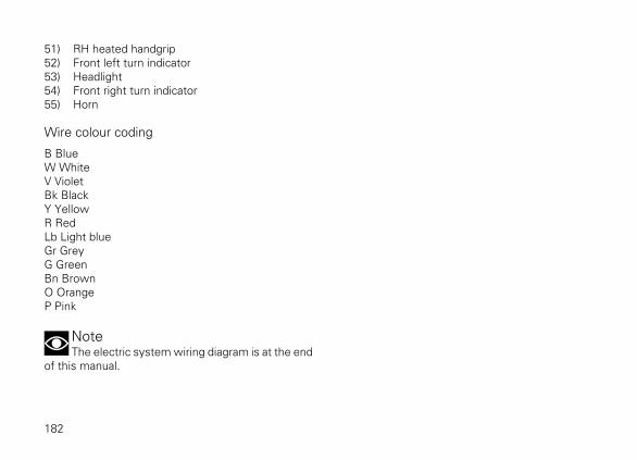
51) RH heated handgrip52) Front left turn indicator53) Headlight54) Front right turn indicator55) Horn
Wire colour coding
B BlueW WhiteV VioletBk BlackY YellowR RedLb Light blueGr GreyG GreenBn BrownO OrangeP Pink
NoteThe electric system wiring diagram is at the end
of this manual.
182

Routine maintenance recordRoutine maintenance record
KM NAMEDUCATI SERVICE
MILEAGE (KM) DATE
1000
12000
24000
36000
48000
60000
183

Cod. 913.7.286.1A
Cod. 913.7.208.1G
Cod. 913.7.208.1F
Cod. 913.7.208.1E
Cod. 913.7.208.1D
Cod. 913.7.208.1C
Cod. 913.7.208.1B
Cod. 913.7.208.1A
Stam
pato 0/2015
3

12
12
34
12
12
12
1 4 5 6 7 8 9 10 13 14 15 16 17 18 19 20 21 22 23 25 26 27 28 29 32 3530 31
21
2 1
DCBA
A 1
A 2
A 3
A 4
B 1
B 2
B 3
B 4
C
1C
2C
3C
4D
1D
2D
3D
4E
1E
2E
3
E 4 F 1
F 2
F 3
F 4
G 1
G 2
G 3
G 4
H 1
H 2
H 3
H 4
J 1
J 2
J 3
J 4
K 1
K 2
K 3
K 4
L 1
L 2
L 3
L 4
M 1
M 2
M 3
M 4
1 2 3 4
2 1
3 2 1
V O
O
4321 4321
V
2 3 4 5
-+
1
12
12
123
12
1 2 3 45 6789101112131415161718
1 2 3 4 5 6 7 8
+ -
30 A
1 2 3 41 2
12
34
56
7
L OOFF
PUSH
Bk Gr
N
RB
L
HILO
R
OFF
PUSH
1 2 3 4 5 6 7 8
RBk BkY
N
RU
D
Y BWRBk RBk
1 2
PUSHBr
Bk
LOCK
PARK
OFF
ON
R G/Bk G/R Y
-- - -
BWBk
FREE
PUSH
RW
OFF
RUN
RBk
4 3 2 1
YY Y
W/Y
CBA
Y
n.c.
W/V
W/V
W/V
W/V
Bk
R
W/Bk
Gr/R
Y/R
Lb/Y
P/Y
Gr/YO/W
Gr/R
WY/B
W/G
Y
W/B
R
W/B
S.C.
P/Y
Bk/B
Bk/B
O/B
kO
/W
Gr/R
W/G
Y
Gr/R
W/B G/YP/Y
O
Y/RY/B
R/Y
Y/B
W/Bk
B
W/BLb
W/R
O W/R
Gr/
G
V
Gr/
B
Bn/Bk
Y
WP/Bk
Y/Gr
Bk
Gr/G Gr/B
Bn/B
kn.
c.
n.c.
n.c.
n.c. n.c.
Lb/W
P/Bk
Gr
Bn/W Bn/W
Bn/W
G/YOshie
ld
S.C.
Y/G
r
Bk B
P/Bk
W/Y
n.c.
Gr
Gr
W
Gr/R LbLbGrV
W
N.C.
BkBN
.C.
R
Bk/BW
N.C.
Gr/R
N.C.
N.C.RW/B
B
W/R Lb Bk/B Lb Bk/B
O
W/R
Lb W GrV
Lb/Y
P/YNC
O/B
k
V
Gr W W/G
W/B
kW
/GW
/Bk
Y/B
Gr
W Gr
Y
Gr/Y
Lb/W
n.c.
n.c.
Bn/W
Y/G
Y/G
Bn/W
Bn/WBn/W
Bn/W
Bn/W
Bn/WBn/W
Bn/W
Bn/W
Bn/W
Bn/W
Bn/W
B/Bk
B/Bk
B/Bk
R
R
RR
RBk/GBk
Bk
BkBk
Bk/G
Bk
Bk/
G
Bk/
G Bk/G
Bk/G
Bk/G
BkBk
Bk/G
Bk/G
Bk
Bk/G
Bk/G
Bk/G
Bk/G
Bk/G
R/Y
R/Y
R/Y
R/Y
R
G/B
k
G/B
k
G/Bk
G/B
k
R/Bk
R/Bk
R/Bk
R/Bk
R/Bk
R/Bk
R/Bk
R/B
R/B
R/BR/W
Gr/G
Gr/G
Gr/G
Gr/G
Bk/V
Bk/V Bk/VBk/VBk
/W
Bk/W
Bk/W
Bk/W
Bk/W Bn/G
Bn/G
Bn/G
R/Bk R/Bk
Bk/GBk/G
Bk
Bk
Gr/G
G/Bk
1 2
3 45 6 7 8 10 11
1213
14 15
16
18
19
2021
22 23
24252629
30313233343536
37
38
394041
42
4344
4546
47
48
49
2728
179
50
51
52
53
54
55
Scrambler

cod. 913.7.286.1A