OWNER’S MANUAL - Aztec...
20
OWNER’S MANUAL ULTRAGRIND Propane Concrete Grinder and Polisher Powered by the EPA/Carb certified Kawasaki 603cc Engine Meets U.S. Green Building Council LEED IEQ Credit 3.4 Requirements CE, LEED, CARB, EPA, & GS-42 Compliant 201 COMMERCE DRIVE • MONTGOMERYVILLE, PA 18936 215-393-4700 • 800-331-1423 • FAX 215-393-4800 www.aztecproducts.com • facebook.com/aztecproducts www.youtube.com/user/AztecProductsInc1
-
Upload
hoangxuyen -
Category
Documents
-
view
215 -
download
0
Transcript of OWNER’S MANUAL - Aztec...

OWNER’S MANUALULTRAGRIND
Propane Concrete Grinderand Polisher
Powered by the EPA/Carb certified
Kawasaki 603cc Engine
Meets U.S. Green Building Council LEED IEQ Credit 3.4 RequirementsCE, LEED, CARB, EPA, & GS-42 Compliant
201 COMMERCE DRIVE • MONTGOMERYVILLE, PA 18936215-393-4700 • 800-331-1423 • FAX 215-393-4800
www.aztecproducts.com • facebook.com/aztecproductswww.youtube.com/user/AztecProductsInc1

PG. 2 ULTRAGRIND
RespiRatoRy HazaRd infoRmation:Grinding/cutting/drilling of masonry, concrete, metal and other materials can generate dust, mists and fumes containing chemicals known to cause serious or fatal injury or illness, such as respiratory disease, cancer, birth defects or other reproductive harm. if you are unfamiliar with the risks associated with the particular process and/or material being cut or the composition of the tool being used, review the material safety data sheet and/or consult your employer, the material manufacturer/supplier, governmental agencies such as osHa, eU-osHa and niosH and other sources on hazardous materials. California and some other authorities, for instance, have published lists of substances known to cause cancer, reproductive toxicity, or other harmful effects.
Control dust, mist and fumes at the source where possible. in this regard use good work practices and follow the recommendations of the manufacturers or suppliers, osHa, niosH, and occupational and trade associations. Water should be used for dust suppression when wet cutting is feasible. When the hazards from inhalation of dust, mists and fumes cannot be eliminated, the operator and any bystanders should always wear a respirator that is approved for the materials being used.
siliCosis WaRninG infoRmation:Grinding/cutting/drilling of masonry, concrete, metal and other materials with silica in their composition may give off dust or mists containing crystalline silica. silica is a basic component of sand, quartz, brick clay, granite and numerous other minerals and rocks. Repeated and/or substantial inhalation of airborne crystalline silica can cause serious or fatal respiratory diseases, including silicosis. When using the equipment with such materials, always follow all dust control and respiratory precautions.
Wear approved respiratory protectionwhen the machine is operating.

impoRtant safety instRUCtionsRead and observe all danGeR, WaRninG, and CaUtion statements included in the owner’s manual and affixed to the machine. these statements indicate that there is a possibility of death, bodily injury, and damage to the machine or property if these instructions are ignored.
operate only in well ventilated areas. Buildings must be provided with:A. A continuous mechanical ventilation that removes the products of combustion to the outdoors of not less than 300 CFM for each 10,000 BTUH or fraction thereof; orB. Natural ventilation of not less than 300 CFM for each 10,000 BTUH input or a fraction thereof; based on a maximum of one-quarter air exchange per hour for the net building volume.if you smell lpG gas, stop the unit and check for leaks. also open windows, don’t touch electrical switches, extinguish any open flames. Call your gas supplier if no leaks are found.do not adjust the fuel system without the proper analysis equipment.
this machine emits Co (carbon monoxide), which is a colorless, odorless, non-irritating gas. symptoms of Co exposure include headache, drowsiness, dizziness and nausea. if you experience any of these symptoms during machine operation, immediately shut off the machine and go outside for fresh air. Have a qualified service technician test the machine for Co emissions before using it again.
High exposure to Co may result in vomiting, confusion, collapse, loss of consciousness and muscle weakness. if such symptoms occur, call for emergency medical attention. do not operate this machine or other propane powered equipment until cleared to do so by a physician. excessive exposure to Co can result in death.never change or alter the propane control components.this machine is factory equipped with engine components and emission controls that maintain harmful exhaust emissions below certified acceptable levels. never tamper, adjust, or remove any factory installed engine components for purposes other than maintenance, repair or replacement. never tilt the equipment on its side for pad, belt or brush replacement. it is designed to tilt back on its rear wheel and handle for maintenance and repair. a second person should aid in lifting and securing equipment for repair.never tilt & transport while engine is running.Keep hands and feet clear of all moving parts.never try to replace parts or repair equipment with machine running.turn the gas off at the tank to kill the engine.Remove the lpG tank and store it in an approved area when not in use. a “no smoKinG” sign should be permanently displayed at the storage area.always vent an over-full bottle using the tank’s bleed valve, out of doors away from all closed places and away from any fire or flame producing device. Vent until the white vapor turns clear.this machine is intended for use with vapor withdraw propane cylinders only. neVeR use a liquid withdraw propane cylinder with this equipment. do not overfill the cylinder. if the regulator or regulator connection freezes, stop the machine and take the cylinder outdoors. inspect cylinder and purge the cylinder using the bleeder valve if necessary.
do not store or use gasoline or other flammable vapors and liquids in the vicinity of this machine. always store equipment away from heater rooms, boilers, gas-fired water heaters or any other source of open flame. propane is highly flammable. always store lpG tanks (full or empty) outside in a secure, well ventilated area.no smoKinG, no spaRKs, no flames neaR Unit oR lpG tanK.
ULTRAGRIND PG. 3

Keep all objects clear of the exhaust system during and after operation.do not leave this machine unattended while the engine is running.
do not operate equipment in one location for more than a few seconds. damage to floor surface can occur.always store equipment away from possible damage by falling objects in warehouse-type areas. always store lpG tanks outside in a secure, well-ventilated area.the muffler and engine become hot enough during operation to cause severe burns. these parts remain hot for a long time after the machine has been shut off. do not touch these parts until they have cooled.safety goggles, safety shoes and safety clothing are recommended while operating the machine.Continuous exposure to high noise levels can cause hearing loss. Hearing protection must be worn while the machine is in operation. the operational weighted sound level of this machine is less than 89dB(a). all noise area precautions must be followed.prolonged exposure to machine vibration may cause tingling or numbness in the fingers and hands. Use of gloves and limits to operator vibration exposure are recommended to prevent such symptoms. the operational hand/arm vibration level of this machine is less than 2.5m/s 2.When lpG tank is attached to the machine and not running, the operator should not leave the machine unattended except for short periods of time such as rest stops, washroom or meal stops.the operator must completely understand all instructions, warning and operating procedures before using this machine.this machine must be maintained in accordance with this manual’s recommended maintenance instructions and the engine manufacturer’s recommended maintenance procedures. failure to do so may cause damage to the machine, equipment, furniture, buildings or personal injury. a maintenance record should be kept indicating date of service, hours on engine, and work done.
Before attempting any maintenance procedures, close the service valve on the fuel cylinder and stop the engine.if you smell propane odor, stop the engine, remove the cylinder and take it outside for inspection.exhaust parts are extremely Hot. do not allow them to come into contact with anything or anyone.do not attempt to change diamonds while the engine is running. do not stand on machine.
GUide to GRapHiCal symBols and pRodUCt laBels
Read all instructions before using
Hot surface – Do Not Touch
Wear hearing protection when operating
Wear safety goggles when operating
Wear respiratory protection
Switch “On” Position
Switch “Off” position
Refer to page 13 of this manual for a location and description of all safety labels and controls.
follow the instructions given in this booklet, the engine’s owners manual and the training given by your supervisor for the safe operation of this machine. failure to do so can result in personal injury and/or damage to the machine or property.
PG. 4 ULTRAGRIND

DO NOT OPERATE THIS MACHINE IN ANEXPLOSIVE ENVIRONMENT!
THIS PROPANE MACHINE IS INTENDED FORCOMMERCIAL USE.
TRANSPORTING THE MACHINENEVER TRANSPORT WHILE ENGINE IS RUNNING.
To transport the machine it is necessary to install thetransport wheel so the drive plates are not in contactwith the floor. In this “balanced” position theequipment can be readily moved from site to site.
A. Tilting the Machine
This is a heavy piece of equipment. Cautionshould be used in tilting the machine. This canbe accomplished safely and easily as follows:
1. One man method:a. Standing behind the machine, place one
foot on the brace at the base of the propane tank.
b. Place one hand on the handle and the other on the “T” frame handle support.
c. While pulling and leaning back, lift the other foot off the floor and extend it directly behind. This will shift the balance and naturally tilt the equipment to transport or full “tilt back” position without undue strain.
2.Two man method:Two people side by side perform the above procedure simultaneously. This is a safer, more comfortable technique to use until moreexperience is gained with the equipment.
Do not use excessive vertical pressure.
B. Position for Maintenance & Cleaning
To perform certain maintenance & cleaning tasks orto change diamonds, the machine should be placedin the full “tilt back” position. See page 8 for moreinformation about maintenance and cleaning.
PREPARATIONFlange bearing must be lubricated beforeevery use. See page 8 for more informationabout the flange bearing.
A. Check that the suggested maintenanceschedule has been observed. See page 8-9 formore information about suggested machine andengine maintenance instructions.
All machines are equipped with a multi-functionmaintenance meter. The functions include thefollowing: hour meter, service alert and tachometer.(See Engine Maintenance Meter instructions pg. 9).
B. Check the engine oil before every operation.
Make sure the machine is level when checking theoil. Always take 2 readings of the dipstick beforeadding oil. If the oil level is below the full mark, addjust enough oil to the engine to bring the oil levelup to the full mark. Never over fill. Follow theguidelines in your Engine Owners Manual. Checkfor foreign material on the dipstick.
C. Properly fill and check your LPG tank and allLPG fuel lines for leaks.
1. Every tank has been pressure and leak tested. However, every time a tank is filled and/or connected to the machine it should be soap tested. All LPG lines must be pressurized and every inch of line and connections must be sprayed. If you find a leak, make the proper repairs before operating the machine. NOTE: The connection and disconnection of the LPG tank must be done in a well ventilated area with NO source of ignition within 10 feet(3 meters) from the point of connection.
2. Never over fill the LPG tank! The LPG tankis designed to hold just 20 pounds of propane. Make sure to weigh the tank as it is being filled. The gross weight of a full tank should not exceed 48 pounds. If while operating the machine, you notice frost forming on the LPG lines or the regulator, your tank has been over filled. If you continue to operate the machine in this condition, damage will occur. The excess propane in the tank must be removed before normal operations resume. The bleeding of a propane tank should be done in a safe location outside the building. In some cases the regulator must defrost before restarting the engine.
D. Connecting the high pressure hose to the LPGTank:
Make sure the couplers are in line and screwedtogether hand tight. If this is not done properly, fuelwill not pass through to the regulator. Nevercomplete the connection of the tanks to the machineby using a wrench. Always do it by hand. Listen forthe rush of fuel to the lock-out device when you openthe tank valve. If you hear this, it indicates a goodconnection has been made at the tank.
ULTRAGRIND PG. 5

NEVER CHANGE OR ALTER THE PROPANECONTROL EQUIPMENT.
SAFETYProvide and use ear protection during operation.
NEVER TILT THIS MACHINE ON ITS SIDE.
Never let an untrained person operate orperform repairs on the machine. They may hurtthemselves, damage the floor or the equipment.Engine speed not to exceed 3400 RPM.
DO NOT use machine with a damaged ordisintigrated pad to avoid excess vibration.
Do not use on surfaces with a gradientexceeding 2%.
OPERATING PROCEDURESA. Adjusting the Handle HeightThe UltraGrind is equipped with a telescoping andadjustable handle.
UltraGrind Transport Handle Position
Diamond Change Handle Position
Operating Handle Position
B. Plate Assembly and Diamond Installation
Resin Bond Metal Bond with 3 Screws
Metal Bond with 1 Screw Resin Bond
1. Close service valve on fuel cylinder to prevent liquid from getting into the regulator.
2. Tilt machine back to access the drive pad
3. Align diamond shoe with slots in drive padand push firmly into slot.
4. Examine red flex plate disc for signs of wear;see daily maintenance requirements.
C. Transport Wheel
Remove transport wheel before operating machine
1. Extend handle to fully extended position.
2. Press downward on the handle bar until it
3. Release locking pin on transport wheel bracket & remove transport wheel.
rests on the ground.
1st Hole
Handle pinnedin 2nd hole
Wheel bracket
Handle fullyextended
Close up of handle in pivot bracket
Handle pinnedin 1st hole
Close up of handle in pivot bracket
Locking pin
PG. 6 ULTRAGRIND

ULTRAGRIND PG. 7
4. Transport wheel can be turned so wheel is in the up position & installed into bracket for storage; make sure the locking pin is securely engaged. The transport wheel may also be stored separate from the machine.
d. Wheel adjustment
Turn clockwise to lowerTurn counter-clockwiseto raise
Loosen 1/2-13 bolt
Wheel adjustment must be made to both wheels on level floor.
1. Loosen 1/2-13 x 1 1/4” bolt 2. Loosen 1/2-13 jam nut just above axle bracket3. Adjust machine height by turning the
1/2-13 x 5” bolt counter clockwise to raise machine or clockwise to lower machine
4. Tighten 1/2-13 jam nut5. Tighten 1/2-13 x 1 1/4” bolt
e. Rear Wheel setting
GAP
Gap factory setting is 2”. Set gap as shown in diagram.f. installing the fuel Cylinder
1. Take UltraGrind to well ventilated area2. Check cylinder for overfill3. Place cylinder on the machine in tank
holding area and secure the safety strap4. Connect fuel cylinder to the machine,
tighten hand tight. Do not use a wrench or pliers or cross thread
5. Open the service valve slowly, be alert for the odor of propane which may indicate a leak
6. To remove the cylinder, reverse the procedureG. Before operating the UltraGrind
• Check oil level • Check carburetor air filter • Check diamonds and diamond plates • Adjust handle height • Install fuel cylinder in a well ventilated area
H. Before you start the engine
do not allow machine to come into contact with loose tiles or other obstructions on the floor. the abrasives will be turning at approximately 650 Rpm. if objects are hit, they could become dangerous projectiles!
• Extend the handle and tilt machine back until handle rests on floor.
• Install diamonds and remove transport wheel.• Bring machine back to operating position.• Fill water tank if wet grinding.
i. preparing to start the engine1. First - check fuel cylinder for overfill and
install cylinder onto machine.2. Place machine on level surface and check
for correct oil level.3. Attach lanyard kill switch clip to the operator.
The lanyard kill switch is a safety switch used if the operator would fall or lose control of the machine; the lanyard will pull away from the switch and kill the engine. The lanyard must be securely fastened to the operator with the attached clip fastener. If the lanyard should become disengaged from the switch, it can simply be reattached to the switch and engine can be restarted. The lanyard kill switch, when activated, will ground the ignition coils, resulting in no spark to the spark plugs, stopping the engine. If the lanyard should become disengaged from the switch and the machine is no longer going to be used, the tank valve must be closed and the ignition key turned to the off position.
J. transporting the machine1. The tank should be securely fastened.2. The tank valve must be closed.
staRtinG tHe enGine 1. Open propane (LPG) tank valve (counter
clockwise).2. Turn the key to start position and move
throttle towards fast position.3. If engine does not start, release the key,
then try again.4. Equipment is supplied with a centrifugal
clutch. When engine RPM is lower than 1800 RPM clutch will disengage; drivers will stop.

5. Increase throttle to about 75% while walking very slowly.
a. never tilt back machine while engine is running.stoppinG tHe enGineTurn the propane tank valve clockwise to a closed position and turn the key OFF.NOTE: The exhaust system will be very hot and takes several minutes to cool, so keep yourself and all materials clear.maintenanCea. Cleaning the equipment 1. Place machine in “tilt back” position. 2. Rinse the drive unit and drivers. 3. Rinse around splash skirt and body. 4. Return machine to operating position, then start engine and run machine briefly to expel any excess water.B. storing the machine and tank 1. The engine should be stopped properly and the tank valve closed. 2. Remove the LPG tank from the machine and store the tank in a well ventilated approved area. 3. Store your machine in a safe area: away from enclosed high heat, away from sparks or flames, and away from traffic lanes of heavy equipment.C. flange Bearings The Flange Bearings must be lubricated with grease before every use or every 4 hours of run time, whichever comes first, or warranty of Flange Bearings will be voided.d. machine & engine maintenance 1. Refer to engine manufacturer’s Owners Manual and comply completely with the instructions. Change the oil and filter according to the engine Owners Manual. 2. Keep a good service log on each machine with the date, hour meter reading, type(s) of service performed and the name of the person who performed them. 3. Clean the entire unit after each use. When cleaning the unit, check for possible loose nuts and bolts. 4. The foam engine dust filter should be removed and cleaned periodically by shaking out the accumulated dust and rinsing with water and a mild detergent. Squeeze out excess water (do not wring out). Allow the filter to air
dry before replacing. Failure to the engine filter clean may result in engine overheating.Changing Gear drive lubricant After the first 100 hours of operation, drain out initial oil, flush out the gear case with an approved nonflammable, non-toxic solvent and refill. Thereafter, oil should be changed at least every 500 operating hours, or every 6 months, whichever comes first, with Mobilgear 630 oil or equivalent.e. maintenance scheduleRepairs and adjustments to the fuel system must be performed by an authorized, properly trained service technician. To keep the machine in good working condition, follow the daily, weekly and monthly maintenance procedures listed below. Keeping the machine clean and free of accumulated dust, lint and oil allows free air to flow across the engine and proper cooling. Always use clean recoil dust filters.These can be cleaned by washing them in flowing water and shaking them dry. Keep a log book of maintenance and/or repairs.daily maintenanceevery two hours of operation:Change or vacuum clean the recoil dust filter.Check and clean carburetor pre-filter.every four hours of operation:Check oil level.Lubricate Flange Bearings.Make sure all components (shroud, handle, fuel cylinder, belt, etc) are tight and secure.Check drive plates and flex material for cracks or diamond wear.Clean machine – if compressed air is available, blow dust from machine and engine, concentrating on the inside of engine shrouds, and wash undercarriage.Weekly maintenance: every 20–50 hours of operationPerform all daily maintenance services.Change oil and oil filters at 50 hours of service.Check for loose nuts and bolts on entire machine.Examine all propane fuel components for leaks or wear, replace if necessary.monthly maintenance: every 80 hours of operationPerform all daily and weekly services.Change carburetor air filter.Consult engine owner’s manual for maintenance services.
Quarterly maintenance: every 250 hours of operation
PG. 8 ULTRAGRIND

Perform all daily, weekly and monthly services.Have engine checked by an authorized service center professionals.Have engine emissions checked by an authorized service center professionals.servicing the UltraGrindProper maintenance of the UltraGrind is the responsibility of the owner and/or the operator.Be sure to go through this checklist on a regular basis:Check oil level.Check and clean air and dust filters.Keep machine clean and lubricated.Clean entire machine after each use, including under the gear drive assembly—engine must be cool before water is used to prevent warping and other damage.Clean carburetor air filters after four hours running time, and clean or replace daily before operation.Check for wear on drive plates and flex hubs daily, replace if damaged.Promptly report any damaged or worn parts to supervisor.Servicing and adjusting of the propane fuel system should only be done by a trained, authorized professional.
f. engine maintenance meterThis multi-function meter acts as a preventive maintenance tool, which benefits you with increased fuel economy, less down-time and longer engine life.The meter’s displays are:Hour meter: Displays total run hours when machine is off.tachometer: Indicates engine RPM during operation.service alert: The display flashes to alert you to lube and change the oil at 25 hour intervals. The service alert only flashes during operation and it warns you to change the oil for only two hours. After the two hours is reached, the alert will automatically reset to the next 25 hour interval. Therefore, it is recommended that a separate maintenance log be kept to track oil changes.maintenance log be kept to track oil changes.
Remember that being safe is a full-time, every day job. follow all information posted on the machine and the lpG tank.never allow anyone to operate this machine who has not read or cannot understand the given instructions.G. troubleshooting the electrical system
1. Check all wire connections for obvious problems. Remove LPG tank, then remove battery box cover. Check all connections visibly and physically. If any “loose”, damaged or unconnected wires are noticed, replace or repair as needed.
2. Check the battery posts and wires. Always wear a face shield, safety glasses and protective clothing when working around a battery. The gases can be explosive and the acid is highly corrosive to metals, cloth and ALL HUMAN TISSUE (skin, eyes, etc.) If the battery post(s) are corroded, remove the wires and clean posts and wires. Applying some axle grease on the posts of the battery after they are cleaned will slow down the battery corrosion process. If nothing obvious is noted, a more detailed investigation is warranted. Before any such troubleshooting begins, the following things should be done:a. Replace propane LPG tank with one from
a machine that runs.b. Charge the battery or provide an absolute
source of 12 volt DC power capable of 50 amperes total output. (A pair of good jumper cables from your car or truck battery will suffice.) Equip yourself with an inexpensive 12 volt test light.
c. If the trouble seems to be in the electrical control equipment, you may disconnect the starter from the system so as to check the system without spinning the engine.
d. Battery rundown. A common problem is letting the battery run down. What usually happens is that it takes the crew a few jobs to get used to the whole system, so the machine is stopped and started quite often. Key left in On position, when engine is turned off, will result in battery running down—dying.
never attempt to adjust the fuel system of a propane engine! if equipped with an emission monitoring or controlling system, never attempt to disconnect or circumvent it.promptly report problems to supervisor.
ULTRAGRIND PG. 9

PG. 10 ULTRAGRIND
H. Troubleshooting main drive belt
If the engine runs, but the drive unit will not engage,this is usually related to the main drive belt. Withoutremoving the drive unit you can check and fix thefollowing:
1. Remove the two (2) 3/8" bolts holding thebelt cover to the body. Remove the one (1)3/8" bolt holding the muffler bracket to the beltcover. Check if belt tension by pinching belttogether. Belt should depress only 1/2".
2. Check to see if belts have come off of inputpulley or centrifugal clutch. If so, install beltsback on the pulley. Note: If belts come offagain they are probably worn or stretchedand need replacement.
KAWASAKI 603cc ENGINETune-up Specifications
ITEM SPECIFICATIONSIgnition Timing UnadjustableSpark Plugs: NGK BPR4ES
Gap 0.75 mm (0.30 in)
Low Idle Speed 1550 RPMHigh Idle Speed 3400 MAX RPMValve Clearance IN: 0.10-0.15 mm
(0.004-0.006 in)EX: 0.10-0.15 mm(0.004-0.006 in)
NOTE: High and low idle speeds may vary dependingon the equipment on which the engine is used. Referto the equipment specifications.
Engine Oil
Check the engine oil daily before starting the engineotherwise shortage of the engine oil may causeserious damage to the engine such as seizure.
• Place the engine on a level surface. Clean thearea around the oil gauge before removing it.
• Remove the oil gauge and wipe it with a clean cloth.• Pour the oil slowly to “FULL” mark on the oil
gauge.• Insert the oil gauge into the tube WITHOUT
SCREWING IT IN.• Remove the oil gauge to check the oil level. The
oil level should be between “ADD” and “FULL”marks. Do not overfill.
• Install and tighten the oil gauge.
Recommended Oils
The following engine oils are recommended.API Service Classification: SF, SG, SH, or SJ.
Oil Viscosity
Choose the viscosity according to the temperatureas follows:
NOTE: Using multi grade oils (5W-20, 10W-30, and10W-40) will increase oil consumption. Check oillevel more frequently when using them.
Engine Oil Capacity
FS481V 1.7 L (1.8 US qt.) when oil filter is removed
Oil Change
Change oil after first 8 hours of operation.Thereafter change oil every 50 hours.• Run the engine to warm oil.• Be sure the engine (equipment) is level.• Stop the engine.• Open the oil drain valve and drain the oil into suitable container while engine is warm.
WARNING!Hot engine oil can cause severe burns. Allow engine temperature to drop from hot towarm level before draining and handling oil.
Oil Drain Plug• Close the oil drain valve.• Remove oil gauge and refill with fresh oil
(See “Recommended Oils” ).• Check the oil level (see “Preparation” on page
3 for oil level check).
Oil Filter Change• Change the oil filter every 100 hours of
operation.
WARNING!Hot engine oil can cause severe burns. Allowengine temperature to drop from hot to warmlevel before attempting to remove oil filter.
CAUTION! Before removing the oil filter, placea suitable pan under filter connection.• Drain engine oil into a suitable container.
• Rotate the oil filter (A) counterclockwise to remove it.
-20˚C -10˚C 0˚C 10˚C 20˚C 30˚C 40˚C
-4˚F 14˚F 32˚F 50˚F 68˚F 88˚F 104˚F
SAE5W-20
SAE30
SAE40
SAE10W-30/SAE10W-40
!
!

• Coat a film of clean engine oil on seal of new filter.• Install new filter rotating it clockwise until
seal contacts mounting surface (B). Then rotate filter 3/4 turn more by hand.
• Supply engine oil as specified.• Run the engine for about 3 minutes, stop
engine, and check oil leakage around the filter.• Add oil to compensate for oil level drop due
to oil filter capacity (See “Preparation” for oil level check on pg. 3).
Engine oil is a toxic substance. Disposeof used oil properly. Contact you localauthorities for approved disposalmethods or possible recycling.
WARNING!
KAWASAKI ENGINE MAINTENANCE SCHEDULEINTERVAL
MAINTENANCE Daily First 8 hr. Every 25 Hr. Every 50 hr. Every 100 hr. Every 200 hr. Every 300 hr.
Lubricate Pillow Block Bearings •Check and add engine oil •Check for loose or lost nuts and screws •Check for fuel and oil leakage •Check or clean air intake screen •Clean air cleaner foam element •Clean air cleaner paper element •Clean dust and dirt from cylinder and cylinder head fins •Tighten nuts and screws •Change engine oil • •Clean and gap spark plugs •Change oil filter •Replace air cleaner paper element •Clean combustion chambers •Clean and adjust valve clearance •* •Clean and lap valve seating surface •
*After the 1st 50 hours
KAWASAKI ENGINE BATTERY START WIRING DIAGRAM
ULTRAGRIND PG. 11

PG. 12 ULTRAGRIND
ENGINE TROUBLESHOOTINGCOMMON PROBLEMS & PROBABLE CAUSES SOLUTIONS
Engine cranks but will not start• Fuel cylinder is empty Refill cylinder• Shutoff valve is closed Open valve• Clogged, obstructed, kinked or cut fuel or vacuum line Remove obstruction or replace line• Spark plug lead disconnected Connect lead to spark plug• Faulty choke or throttle settings Set controls to correct positions• Faulty ignition coil Replace coil• Faulty kill switch Replace switch• Faulty regulator Replace regulator
Engine starts hard• Faulty choke or throttle settings Set controls to correct position• Clogged, obstructed, kinked or cut fuel or vacuum line Remove obstruction or replace line• Faulty regulator Replace regulator• Low compression Have engine serviced by a trained technician
Engine will not crank• Battery is discharged Charge or replace battery• Loose or faulty connections or wires Tighten, repair or replace wires• Faulty ignition key switch or starter control switch Repair or replace switch(es)
Engine overheats• Incorrect fuel settings Have engine serviced• Air intake filter screen or cooling fins clogged Clean and clear debris or replace filter • Low oil level Check and add oil
Exhaust emissions or propane odor• Carburetor or regulator setting incorrect Have engine serviced by a trained technician• Dirty or clogged air filter Replace air filter• Choke engaged Adjust to correct settings• Loose fittings, clamps or hoses cracked, Tighten or seal; check with soap and
hoses cut or leaking water solution, if bubbles appear, part is still leaking; replace
REF DESCRIPTION PART # QTY
WATER TANK PARTS
1 WATER TANK STRAP 010-MG-STRAP 22 8 GALLON WATER TANK 010-971MGT 13 WATER TANK BRACKET 288-040-2280 14 QUICK COUPLING INSERT 050-290 15 QUICK COUPLING BODY 050-270 16 HOSE CLAMP 050-320 27 TUBING 216-0609 28 HOSE BARB 050-250 19 WATER VALVE 030-20-1171 110 CLOSE NIPPLE 177-58020 1

ULTRAGRIND PG. 13
Warning label locations
Model: The UltragrindPropane Powered Grinder
Wear approved respiratory protection when the
machine is operating.

PG. 14 ULTRAGRIND
Quick start Guide
1. Read, understand and observe all Important Safety Instructions before operating the machine (See Pg. 2).
2. Make sure the machine is properly maintained prior to use (See Pg. 2).
3. Make sure the LPG tank 1 is filled, connected and checked for leaks.(See Pg. 3).
4. Open the LPG tank by turning the knob 2 anti-clockwise.
5. Set throttle lever 3 to idle [ ] position
6. Turn key 4 to start [ ] position
7. Move throttle lever 3 toward run [ ] position. If motor fails to start, return to Step 5 above.
8. Set throttle lever 3 to desired operating speed and follow the moving machine (straight ahead) at moderate walking pace (keep moving).
1
3 4
2

BODY ASSEMBLY PARTS
REF DESCRIPTION PART # QTY
1 WHEEL ASSEMBLY 156-040 22 BODY FRAME ASSEMBLY 288-040-100 13 RIGHT END PLATE 283-040-900R 14 LEFT END PLATE 283-040-900L 15 VACUUM CAPS 040-3015 26 WHEEL BASE BRACKET 288-040-10 17 TRANSPORT WHEEL BRACKET 288-040-2300 18 TRANSPORT WHEEL 156-040-1 19 BELT COVER 288-040-300 110 LEFT SHIELD 288-040-2290L 111 RIGHT SHIELD 288-040-2290R 112 SPLASH SKIRT 040-200 113 DRIVE COVER ASSEMBLY 288-040-200 114 ACCESS COVER 288-040-2270 1
ULTRAGRIND PG. 15
PG. 16 ULTRAGRIND
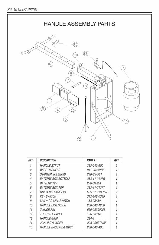
HANDLE ASSEMBLY PARTS
REF DESCRIPTION PART # QTY
1 HANDLE STRUT 283-040-600 22 WIRE HARNESS 011-762 WHK 13 STARTER SOLENOID 296-SS-581 14 BATTERY BOX BOTTOM 283-11-2127B 15 BATTERY 12V 276-GTX14 16 BATTERY BOX TOP 283-11-2127T 17 QUICK RELEASE PIN 625-97320A760 28 KEY SWITCH 312-308-0385 19 LANYARD KILL SWITCH 153-73459 110 HANDLE EXTENSION 288-040-1200 111 T-KNOB PIN 625-09300088 112 THROTTLE CABLE 196-60314 113 HANDLE GRIP 224-1 214 20# LP CYLINDER 293-20#STLMF 115 HANDLE BASE ASSEMBLY 288-040-400 1

ULTRAGRIND PG. 17
WHEEL AXLE ASSEMBLY PARTS
REF DESCRIPTION PART # QTY
1 AXLE NUT 164-36869 22 1⁄2-13 X 2 HCS 164-110120382 23 1⁄2" FLAT WASHER 164-20159 24 ADJUSTMENT SIDE BAR 283-040-1000 45 3⁄8-16 X 1 HCS 164-10115 86 5⁄16 FLAT WASHER 164-20156 167 3⁄8-16 STOVER LOCK NUT 164-22834 88 1⁄2-13 X 5 TAP BOLT 164-50C500BTA52 29 1⁄2" FLAT WASHER 164-20159 410 1⁄2-13 STOVER LOCK NUT 164-22836 211 1⁄2-13 HEX NUT 164-22008 212 T-SLOT NUT 164-731-54338 213 AXLE BRACKET ASSEMBLY 288-040-15 214 AXLE SPACER 040-3010 215 WHEEL ASSEMBLY 156-040 216 COTTER PIN 164-18R200PC02 2

PG. 18 ULTRAGRIND
DRIVE ASSEMBLY PARTS
REF DESCRIPTION PART # QTY
1 GEAR DRIVE ASSEMBLY 040-953 12 1⁄2-13 STOVER LOCK NUT 164-22836 43 1⁄2" FLAT WASHER 164-20159 84 BELT 113-L548 15 1⁄2-13 X 2 HCS 164-110120382 46 BELT TENSIONER 011-6-2795 17 1⁄2-13 X 11⁄4 FSCS 164-50C125KFC 48 7/16-20 X 1 HCS 164-10301 19 WASHER 164-20164 110 DRIVE PULLEY 172-040 111 1⁄8" KEY 199-102935 112 FLANGE BEARING 239-040 213 SUPPORT BRACKET 283-040-2000 114 1⁄2" FLAT WASHER 164-20159 1

ULTRAGRIND PG. 19
PART # DESCRIPTION PART # QTY
1 3/8-16 x 2 1/4 FSCS 164-37C225KSCST 32 3/8-16 X 2 1/2 FSCS 164-37C25KSC 33 DRIVE PLATE 283-040-2255 14 MOUNT SPACER 283-040-2220 15 3/8-16 x 1 1/4 HCS 164-10117-SS 66 HUB 283-040-2230 17 FLEX PLATE 040-2210 18 HUB RING 283-040-2215 19 3/8-16 STOVER LOCK NUT 164-22834 1210 MOUNT RING 283-040-2245 111 3/8-16 HEX NUT 164-22004 312 SAFETY STRAP 283-040-2225 113 5/16-18 x 1 HCS 164-110120325 214 SHAFT LOCK PLATE 283-040-2240 115 3/18-16 X 1 1/4 HCS 164-10117-SS 116 SHAFT END PLATE 283-040-2235 117 1/4" KEY 199-NHNT-SE UND 118 DRIVE PLATE ASSEMBLY 040-2255 319 SHAFT SEAL 040-4000 3
DIAMOND DRIVERS PARTS
PART # DESCRIPTION PART # QTY
1 Foam Hat Filter 186-271964 12 Debris Screen 309-18540 13 Foam Hat Seal 175-7.75*9.25*1 14 Oil Pressure Switch 152-N3-0082 15 Oil Filter 309-49065-7007 16 Oil Drain Valve 312-504-0185 17 1/4 x 1 1/4 Key 199-NHNT-SE UND 18 Centrifugal Clutch 311-180007 19 Exhaust Manifold Gasket 309-11060-7016 210 Exhaust Manifold 152-603-MAN 111 Catalytic Muffler 152-603-MUF 112 Debris Screen Adapter 283-040-2250 113 Air Filter Element 309-11013-7049 114 Foam Pre Filter 309-11013-7046 1
KAWASAKI 603cc ENGINE

ULTRAGRIND WARRANTYThis quality product is warranted to be free from defects in workmanship and materials. Thewarranty is limited as follows:
Component Term of WarrantyEngine 2 yrs from engine manufacturerFuel System 1 yrLP Tank 1 yr on valve, 3 yrs on cylinder from date of mfgr. Body Parts 1 yrBattery 1 yr from battery mfgr.Centrifugal Clutch 1 yrBearings 6 monthsDrive Blocks 6 months
The warranty does not apply to certain consumable or wear parts such as:BeltsEngine tune up parts
All engines are warranted by the manufacturer (Kawasaki) for a period of two years when enginemaintenance schedules are followed.Aztec Products, Inc. agrees, at its discretion, to repair or replace at its own expense any productor part(s) which examination proves to be defective in workmanship or materials provided thatthe purchaser notifies Aztec Products, Inc. directly within the warranty period and follows theReturn Goods Policy. Engine repairs may be performed at engine manufacturer’s service centers.For your closest center you may call the following number:
Kawasaki 616-949-6500The warranty does not apply to damage or failure caused by abuse, misuse, neglect, disassembly,alteration, unauthorized modification, lack of proper maintenance, theft, or damage by freightcarriers. The warranty applies to parts, labor and ground freight only. It does not cover incidentalor consequential damages.In order to obtain parts warranty, the following procedures must be followed:1. Customer must call Aztec Products, Inc. for an RGA (Return Goods Authorization) Number.2. We maintain the serial number, date of shipment or sale, and customer name on each piece ofequipment sold. If you were the purchaser, please reference that information on your request forreplacement or repair. If you purchased the equipment through a distributor, please contact themfirst. If you are not satisfied, contact Aztec and give us the distributor name, purchase date, andthe serial number of the product.3. The defective part must be returned via ground freight prepaid to Aztec Products, Inc. with anRGA number accompanied by a copy of the original purchase invoice. Aztec is not responsiblefor the cost of packaging inbound freight, nor inbound freight damage. Pack machine carefully.4. Only Aztec Products, Inc. or its authorized dealers may make warranty repairs on AztecProducts, Inc. products. Others do so at their own risk and expense.5. We also offer to do warranty related repairs free of charge at our facility. Arrangements mustbe made in advance as outlined above. We will not accept freight collect returns or returns thatdo not indicate the RGA number on the packing list.The need for proper maintenance and care for this product cannot be overstated. Poormaintenance, neglect or abuse can prove to be very expensive.You have purchased a quality product. Each of its components has been tested and approved foruse by Aztec Products, Inc. It is unlikely that you will ever have a warranty claim if you properlymaintain our machine.
This warranty is non-transferable.
AZTEC PRODUCTS, INC.201 Commerce Drive • Montgomeryville, PA 18936 • 800-331-1423 • Fax 215-393-4800
9739/02-2015