OWNER’S MANUAL - An online collection of MINI...
140
OWNER'S MANUAL MINI COOPER MINI COOPER S
Transcript of OWNER’S MANUAL - An online collection of MINI...

OWNER'S MANUAL
MINI COOPERMINI COOPER S
CONGRATULATIONS ON YOUR NEW MINI
This Owner's Manual should be considered a permanent part of this vehicle. It should stay with the vehicle when sold to provide the next owner with important operating, safety and maintenance information.
This manual is supplemented by a Service and Warranty Information Booklet for US models or a Warranty and Service Guide Booklet for Canadian models.
We recommend that you read this publication thoroughly.
Your MINI is covered by the following warranties:
– New Vehicle Limited Warranty
– Limited Rust Perforation Warranty
– Federal Emissions System Defect Warranty
– Federal Emissions Performance Warranty
– California Emission Control System Limited Warranty
Detailed information about these warranties is listed in the Service and Warranty Information Booklet for US models or in the Warranty and Service Guide Booklet for Canadian models.
We wish you an enjoyable driving experience.

CONTENTS
2
Using this Owner'
Notes on the OwneSymbols used 6Symbol for vehicle pYour individual vehEditorial notice 7For your own safetyReporting safety de
Controls and features
Opening and closing:
Keys 22Central locking system 23Opening and closing – from outside 23Opening and closing – from inside 26Tailgate 27Electric power windows 28Sliding/tilt sunroof 29Roller sun blind 30
Adjustments:
Correct sitting posture 31Seats 31Entry to the rear 33
s Manual
r's Manual 6
arts 6icle 6
8fects 9
At a glance
Cockpit 12Display elements 13Display elements with navigation
system 14Indicator and warning lamps 15Multifunction steering wheel MFL 18
Seat heating 34Head restraints 34Safety belts 35Steering wheel 35Mirrors 36Airbags 37Transporting children safely 38Vehicle Memory 41
© 2002 Bayerische Motoren Werke AktiengesellschaftMunich, GermanyReprinting, including excerpts, only with the written consent of BMW AG, Munich. Order No. 01 41 0 156 724US English II/02Printed in GermanyPrinted on environmentally friendly paper (bleached without chlorine, suitable for recycling).
OV
ERV
IEW
OPE
RA
TIO
NC
ON
TRO
LS
Care and maintenance
Special operating instructions:
Break-in procedures 76General driving notes 76Refueling 77Fuel specifications 78Antilock Brake System (ABS) 78Brake system 79
Wheels and tires:
Tire inflation pressure 80Tire condition 82Tire replacement 83Wheel and tire combinations 84Winter tires 85
Driving:Ignition lock 42Starting the engine 42Switching off the engine 43Parking brake 44Manual transmission 45Continuously Variable automatic
Transmission (CVT) 46Parking lamps/Low beams 49Indicator/Headlamp flasher 49Instrument lighting 50Fog lamps 50Interior lamps 50Light-emitting diodes 51Washer/Wiper system 51
Technology for safety and driving convenience:Automatic Stability Control plus Traction
(ASC+T) 60Dynamic Stability Control (DSC) 61Flat Tire Monitor 62Park Distance Control (PDC) 63
Controlling the climate for pleasant driving:Air conditioner system 64Automatic climate control 67
Interior conveniences:Glove compartment 70Ashtray/Beverage holder 70
REP
AIR
SD
ATA
IND
EX
Snow chains 85
Cruise control 53Everything under control:Odometer 55Tachometer 55Fuel gauge 55Coolant temperature gauge 56Service Interval Display 57Clock 57Computer 58
Cigarette lighter 70
Loading and transporting cargo:Luggage compartment cover 71Foldable rear backrest 71Loading cargo 72Roof-mounted luggage rack 73
3
CONTENTS
4
Technical data
Engine data 120Dimensions 121Weights 122Capacities 123Electrical system 124
In the engine compartment:Hood 86Engine compartment –
MINI COOPER 87Engine compartment –
MINI COOPER S 88Washer fluid 89Engine oil 89Coolant 91Brake fluid 92
Maintenance and care:MINI Maintenance System 93Caring for your vehicle 94Vehicle immobilization 96
Owner Service Procedures
Replacement procedures:Onboard tool kit 100Windshield wiper blades 100Lamps and bulbs 101Repairing a flat tire 106Changing tires – MINI
with space-saver spare tire 106Flat tire – safety tires 110Battery 111Fuses 112
Giving and receiving assistance:Warning triangle 113First-aid kit 113
Laws and regulations:OBD interface socket 96Technical modifications 96California Proposition 65 Warning 97
Jump-starting 113Tow-starting and towing 115

OV
ERV
IEW
OPE
RA
TIO
NC
ON
TRO
LS
REP
AIR
SD
ATA
IND
EX
5
Index
Everything from A to Z 128
6
Your individual vehicle
The manufacturer of your MINI is the Bayerische Motoren Werke Aktiengesell-schaft (BMW AG).
On purchasing your MINI, you have decided in favor of a model with individualized equipment and features. This Owner's Manual describes the entire array of options and equipment available with a specific manufacturer model range.
We hope you will understand that equip-ment and features are included that you might not have chosen for your vehicle. To assist you in identifying possible variations
Notes on the Owner's ManualIn compiling this Owner's Manual we have made every effort to furnish you with a convenient reference source affording quick access to all the essentials. The fastest way to find detailed information on any specific subject is to turn to the comprehensive index at the back of the manual. If you wish to gain an initial over-view of your vehicle, you will find this in the first chapter.
Should you wish to sell your MINI at some time in the future, please remember to hand over this Owner's Manual to the new owner; it is an important part of the
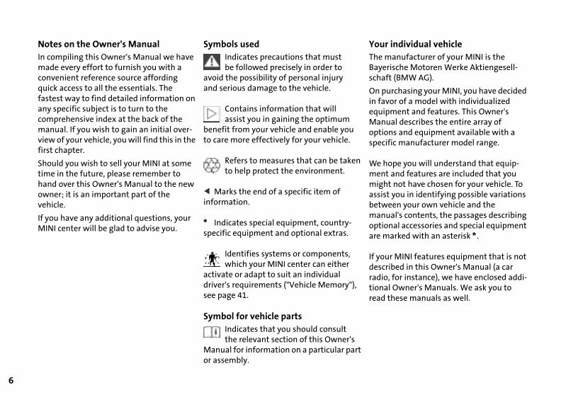
Symbols usedIndicates precautions that must be followed precisely in order to
avoid the possibility of personal injury and serious damage to the vehicle.
Contains information that will assist you in gaining the optimum
benefit from your vehicle and enable you to care more effectively for your vehicle.
Refers to measures that can be taken to help protect the environment.
< Marks the end of a specific item of information.
between your own vehicle and themanual's contents, the passages describing optional accessories and special equipment are marked with an asterisk *.
If your MINI features equipment that is not described in this Owner's Manual (a car radio, for instance), we have enclosed addi-tional Owner's Manuals. We ask you to read these manuals as well.
Notes
vehicle.
If you have any additional questions, your MINI center will be glad to advise you.
* Indicates special equipment, country-specific equipment and optional extras.
Identifies systems or components, which your MINI center can either
activate or adapt to suit an individual driver's requirements ("Vehicle Memory"), see page 41.
Symbol for vehicle partsIndicates that you should consult the relevant section of this Owner's
Manual for information on a particular part or assembly.
SymbolsYour individual vehicle

OV
ERV
IEW
OPE
RA
TIO
NC
ON
TRO
LS
Editorial noticeThe manufacturer pursues a policy of continuous, ongoing development that is conceived to ensure that the MINI continues to embody the highest quality and safety standards combined with advanced, state-of-the-art technology. For this reason, it is possible that the features described in this Owner's Manual could differ from those on your vehicle. Nor can errors and omissions be entirely ruled out.
You are therefore asked to appreciate that no legal claims can be entertained on the basis of the data, illustrations or descrip-tions in this Owner's Manual.
REP
AIR
SD
ATA
IND
EX
7

8
l advice on using these items, are ble from all MINI centers.
lation and operation of non-MINI ved accessories such as alarms,
s, amplifiers, radar detectors, wheels, nsion components, brake dust s, telephones (including operation
y portable cellular phone from within hicle without using an externally ted antenna) or transceiver equip-
(e.g. CB, walkie-talkie, ham radio or r) may cause extensive damage to hicle, compromise its safety, inter-ith the vehicle’s electrical system
ect the validity of the MINI Limited anty. See your MINI center for addi-
d r
-
-
e-
sionaavaila
Instalapproradiosuspeshieldof anthe vemounmentsimilathe vefere wor affWarr
l information.<
Maintenance, replacement, or repair of the emission control devices and
ms may be performed by any automo-epair establishment or individual any certified automotive part.<
o d -
tiona
systetive rusing
For your own safety Use unleaded gasoline only. Fuels containing up to and including
10% ethanol or other oxygenates with up to 2.8% oxygen by weight (i.e. 15% MTBE or 3% methanol plus an equivalent amount of co-solvent) will not void the applicable warranties with respect to defects in mate-rials or workmanship. Field experience has indicated significant differences in fuel quality (volatility, composition, additives, others) among gasolines offered for sale in the United States and Canada. The use of poor-quality fuels may result in driveability, starting and stalling problems especially under certain environmental conditions,
Important safety information.
For your own safety, use genuine parts anaccessories approved by the manufactureof the MINI.
When you purchase accessories tested and approved by the manufacturer of theMINI and Original MINI Parts, you simultaneously acquire the assurance that they have been thoroughly tested by the manufacturer of the MINI to ensure optimum performance when installed on your vehicle.
The manufacturer of the MINI warrants these parts to be free from defects in mat
such as high ambient temperature and high altitude. Should you encounter driveability prob-lems which you suspect could be related to the fuel you are using, we recommend that you respond by switching to a recognized high-quality brand. Failure to comply with these recommenda-tions may result in unscheduled mainte-nance. Obey pertinent safety rules when you are handling gasoline.<
rial and workmanship.
The manufacturer of the MINI will not accept any liability for damages resulting from installation of parts and accessories not approved by the manufacturer of the MINI.
The manufacturer of the MINI cannot testevery product from other manufacturers tverify if it can be used on a MINI safely anwithout risk to either the vehicle, its operation, or its occupants.
Original MINI Parts, MINI Accessories andother products approved by the manufac-turer of the MINI, together with profes-
9
OV
ERV
IEW
REP
AIR
SO
PER
ATI
ON
CO
NTR
OLS
DA
TAIN
DEX
the US.
a crash or could cause injury or death, you should immediately HTSA) in addition to notifying BMW of North America, LLC., (201) 307-4000.
tion, and if it finds that a safety defect exists in a group of , NHTSA cannot become involved in individual problems
toll-free at 1-800-424-9393 (or 366-0123 in Washington, D.C. ashington, D.C. 20590. You can also obtain other information
The following only applies to vehicles owned and operated in
REPORTING SAFETY DEFECTSIf you believe that your vehicle has a defect which could causeinform the National Highway Traffic Safety Administration (NP.O. Box 1227, Westwood, New Jersey 07675-1227, Telephone
If NHTSA receives similar complaints, it may open an investigavehicles, it may order a recall and remedy campaign. Howeverbetween you, your dealer or BMW of North America, LLC.
To contact NHTSA, you may either call the Auto Safety Hotlinearea) or write to: NHTSA, U.S. Department of Transportation, Wabout motor vehicle safety from the Hotline.
10

OVERVIEW
CONTROLS
OPERATION, CARE, MAINTENANCE
OWNER SERVICE PROCEDURES
INDEX
TECHNICAL DATA
11
OV
ERV
IEW
REP
AIR
SO
PER
ATI
ON
CO
NTR
OLS
DA
TAIN
DEX
Overview
12
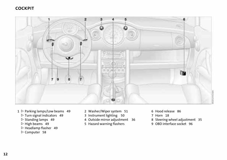
COCKPIT
beams 49
rs 49
49
2 Washer/Wiper system 513 Instrument lighting 504 Outside mirror adjustment 365 Hazard warning flashers
ood release 86orn 18teering wheel adjustment 35BD interface socket 96
6 H7 H8 S9 O
1 > Parking lamps/Low > Turn signal indicato> Standing lamps 49>High beams 49>Headlamp flasher> Computer 58
OV
ERV
IEW
OPE
RA
TIO
NC
ON
TRO
LS
DISPLAY ELEMENTS
ning lamps, see
58
cator and warning 5
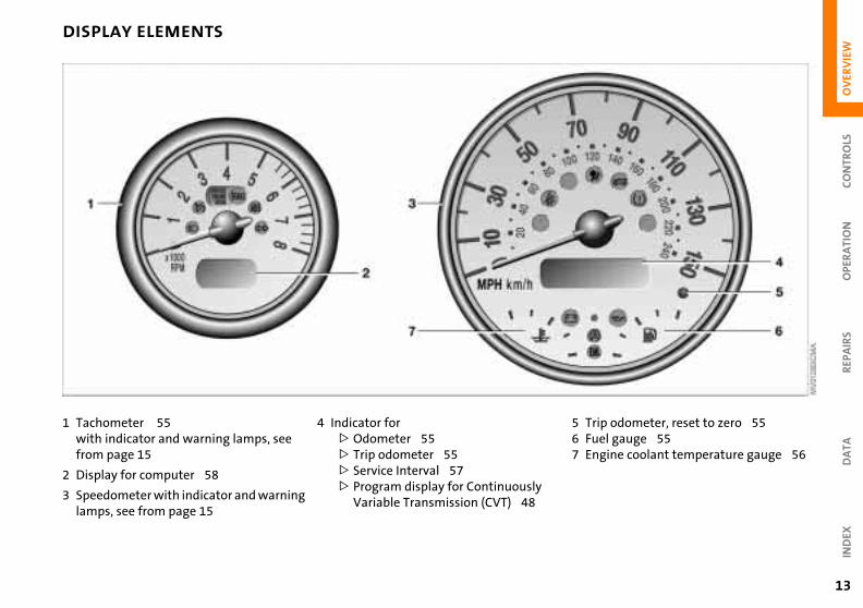
4 Indicator for
>
Odometer 55
>
Trip odometer 55
>
Service Interval 57
>
Program display for Continuously Variable Transmission (CVT) 48
REP
AIR
SD
ATA
IND
EX
ip odometer, reset to zero 55el gauge 55gine coolant temperature gauge 56
5 Tr6 Fu7 En
13
1 Tachometer 55with indicator and warfrom page 15
2 Display for computer
3 Speedometer with indilamps, see from page 1
14
DISPLAY ELEMENTS WITH NAVIGATION SYSTEM
*
ing lamps, see
8
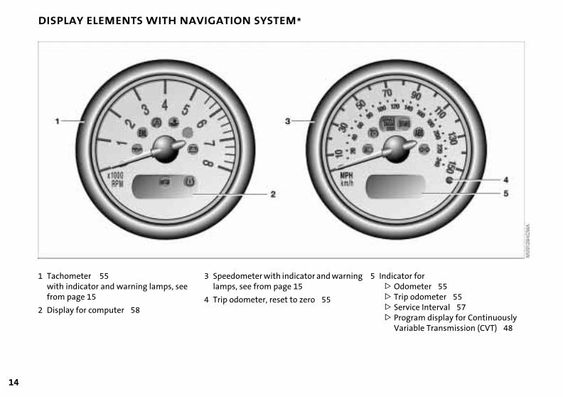
3 Speedometer with indicator and warninlamps, see from page 15
4 Trip odometer, reset to zero 55
icator for
Odometer 55
Trip odometer 55
Service Interval 57
g 5 Ind>>>
Program display for Continuously Variable Transmission (CVT) 48
>
1 Tachometer 55with indicator and warnfrom page 15
2 Display for computer 5
OV
ERV
IEW
REP
AIR
SO
PER
ATI
ON
CO
NTR
OLS
DA
TA
INDICATOR AND WARNING LAMPS
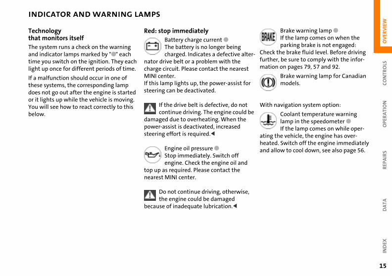
Brake warning lamp
●
If the lamp comes on when the parking brake is not engaged:
k the brake fluid level. Before driving er, be sure to comply with the infor-on on pages 79, 57 and 92.
Brake warning lamp for Canadian models.
navigation system option:
Coolant temperature warning lamp in the speedometer
●
If the lamp comes on while oper- the vehicle, the engine has over-
ed. Switch off the engine immediately allow to cool down, see also page 56.
er-
r
be
,
Checfurthmati
With
atingheatand
IND
EX
15
Technologythat monitors itself The system runs a check on the warning and indicator lamps marked by "●" each time you switch on the ignition. They each light up once for different periods of time.
If a malfunction should occur in one of these systems, the corresponding lamp does not go out after the engine is started or it lights up while the vehicle is moving. You will see how to react correctly to this below.
Red: stop immediatelyBattery charge current ●The battery is no longer being charged. Indicates a defective alt
nator drive belt or a problem with the charge circuit. Please contact the nearestMINI center.If this lamp lights up, the power-assist fosteering can be deactivated.
If the drive belt is defective, do not continue driving. The engine could
damaged due to overheating. When the power-assist is deactivated, increased steering effort is required.<
Engine oil pressure ●Stop immediately. Switch off engine. Check the engine oil and
top up as required. Please contact the nearest MINI center.
Do not continue driving, otherwisethe engine could be damaged
because of inadequate lubrication.<

16
INDICATOR AND WARNING LAMPS
an important reminder
Brake warning lampwith parking brake applied. More information on the parking
on page 44
Parking brake lamp for Canadian models.
Fasten safety belts
●
Depending on model, with acoustic signal
*
. Lights up either for several ds or until the belt is engaged, de-
ing on version. information on page 35
Depending on the level of equipment, the indicator lamp is in the vicinity of
avigation system.
<
Airbags
●
Please have the system inspected at your MINI center.
information on pages 31, 37
Depending on the level of equipment, the indicator lamp is in the vicinity of
avigation system.
<
h V
e
h s -
Red:
brake
seconpendMore
the n
More
the n
Hood/tailgateLights up when the hood and/or tailgate are open.
information on pages 27, 86
MoreYellow: stop immediatelyFlat Tire Monitor ●
Flashes: tire failure.
Reduce speed immediately and stop the vehicle.
With safety (run-flat) tires:Reduce vehicle speed carefully to under 50 mph (80 km/h).
In both cases, avoid hard brake applications and steering maneuvers. Check the tire inflation pressures.Conduct in the event of a flat tire, see pages 106, 110.
General information on the system, see
Red and yellow: continue to drive; drive cautiously
Brake warning lamp together wityellow indicator lamps for ABS, EBand ASC+T/DSC:The control system ABS, EBV and ASC+T/DSC has failed. Drive cautiously and defensively. Avoidfull brake applications. Please havthe system checked by your MINI
center as soon as possible. More information on pages 60, 61
Brake warning lamp together witthe yellow indicator warning lampABS, EBV and ASC+T/DSC for Cana
page 62 dian models.
OV
ERV
IEW
REP
AIR
SO
PER
ATI
ON
CO
NTR
OLS
DA
TA
INDICATOR AND WARNING LAMPS
n: for your information
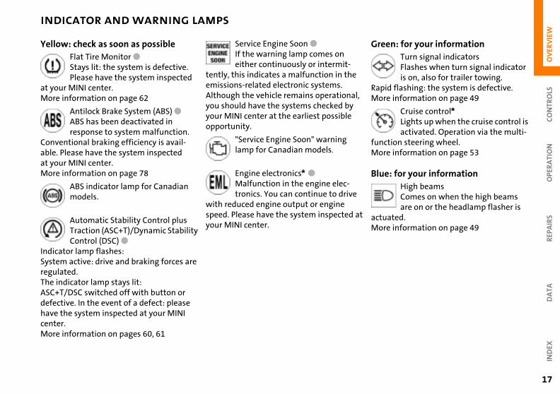
Turn signal indicatorsFlashes when turn signal indicator is on, also for trailer towing.
d flashing: the system is defective. information on page 49
Cruise control
*
Lights up when the cruise control is activated. Operation via the multi-
tion steering wheel. information on page 53
: for your information
High beamsComes on when the high beams are on or the headlamp flasher is
ated. information on page 49
l,
at
Gree
RapiMore
funcMore
Blue
actuMore
IND
EX
17
Yellow: check as soon as possibleFlat Tire Monitor ● Stays lit: the system is defective. Please have the system inspected
at your MINI center.More information on page 62
Antilock Brake System (ABS) ●ABS has been deactivated in response to system malfunction.
Conventional braking efficiency is avail-able. Please have the system inspected at your MINI center. More information on page 78
ABS indicator lamp for Canadian models.
Service Engine Soon ●If the warning lamp comes on either continuously or intermit-
tently, this indicates a malfunction in theemissions-related electronic systems. Although the vehicle remains operationayou should have the systems checked by your MINI center at the earliest possible opportunity.
"Service Engine Soon" warning lamp for Canadian models.
Engine electronics* ●Malfunction in the engine elec-tronics. You can continue to drive
with reduced engine output or engine
Automatic Stability Control plus Traction (ASC+T)/Dynamic Stability Control (DSC) ●
Indicator lamp flashes: System active: drive and braking forces are regulated. The indicator lamp stays lit: ASC+T/DSC switched off with button or defective. In the event of a defect: please have the system inspected at your MINI center.More information on pages 60, 61
speed. Please have the system inspected your MINI center.
18
MULTIFUNCTION STEERING WHEEL MFL
*
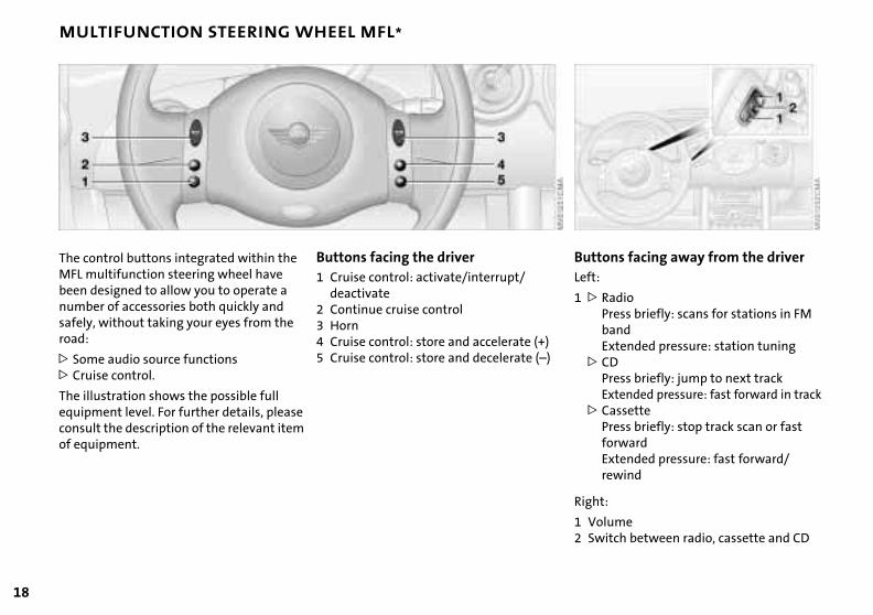
ntrol: store and accelerate (+)ntrol: store and decelerate (–)
ns facing away from the driver
adioress briefly: scans for stations in FM andxtended pressure: station tuning
Dress briefly: jump to next trackxtended pressure: fast forward in track
assetteress briefly: stop track scan or fast orwardxtended pressure: fast forward/ewind
ButtoLeft:
1 > RPbE
> CPE
> CPfEr
:
lumeitch between radio, cassette and CD
Right
1 Vo2 Sw
The control buttons integrated within the MFL multifunction steering wheel have been designed to allow you to operate a number of accessories both quickly and
Buttons facing the driver1 Cruise control: activate/interrupt/
deactivate2 Continue cruise control
safely, without taking your eyes from the road:
> Some audio source functions> Cruise control.
The illustration shows the possible full equipment level. For further details, please consult the description of the relevant item of equipment.
3 Horn4 Cruise co5 Cruise co

OV
ERV
IEW
OPE
RA
TIO
NC
ON
TRO
LS
REPA
IRS
DA
TAIN
DEX
19
20

OVERVIEW
CONTROLS
OPERATION, CARE, MAINTENANCE
OWNER SERVICE PROCEDURES
INDEX
TECHNICAL DATA
21
OV
ERV
IEW
REP
AIR
SO
PER
ATI
ON
CO
NTR
OLS
DA
TAIN
DEX
Controls

22
KEYS
lizing the master key with remote ol
you activate a master key with te control (replacement, additional r after a battery change), it must be lized.
nitialization can be performed in two :
button 1 or button 2, see page 24, imes in succession
vehicle is unlocked:itch the ignition on briefly (position 2) d then off
InitiacontrWhenremokey oinitia
This iways
Pressfour t
or
if the1. Sw
an
thin 10 seconds, press button 1 and tton 2, see page 24, in succession.In the event of a system malfunction, please contact your MINI center. You
lso obtain replacement keys and ries there.<
e
2. Wibu
can abatte
Depending on the equipment fitted, your MINI has up to three key variations:
1 Master key with remote control and battery
Changing batteryReplace if it is no longer possible to unlockthe vehicle via the remote control.
If the battery is discharged, please consult your MINI center. Battery
changing, see next column.<
2 Door and ignition keyThis key can only be used to open the doors mechanically
3 Spare key for storage in a safe place, such as in your wallet. This key is not intended for constant use
Only use a battery of the type speci-fied on the battery (CR 2032) and
make absolutely sure that it is fitted in thcorrect position.<
1. Apply a screwdriver at the recess2. Use the screwdriver to lever out the
cover.
Return used batteries to a recycling point or your MINI center.<
OV
ERV
IEW
OPE
RA
TIO
NC
ON
TRO
LS
CENTRAL LOCKING SYSTEM OPENING AND CLOSING – FROM OUTSIDE
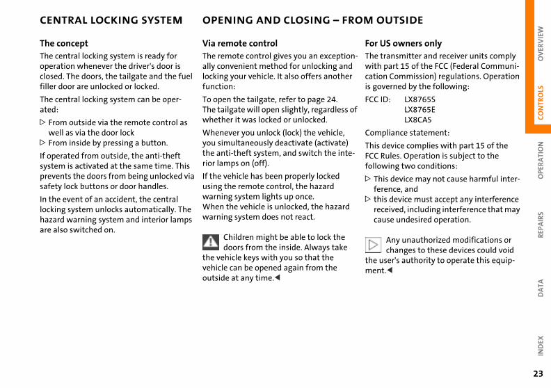
S owners only
ransmitter and receiver units comply part 15 of the FCC (Federal Communi-n Commission) regulations. Operation verned by the following:
ID: LX8765SLX8765ELX8CAS
pliance statement:
device complies with part 15 of the Rules. Operation is subject to the wing two conditions:
is device may not cause harmful inter-rence, and
is device must accept any interference
n-d r
of
-
For UThe twithcatiois go
FCC
Com
This FCC follo
> Thfe
> th
23
REP
AIR
SD
ATA
IND
EX
ceived, including interference that may use undesired operation.
Any unauthorized modifications or changes to these devices could void
ser's authority to operate this equip-t.<
reca
the umen
The conceptThe central locking system is ready for operation whenever the driver's door is closed. The doors, the tailgate and the fuel filler door are unlocked or locked.
The central locking system can be oper-ated:
> From outside via the remote control as well as via the door lock
> From inside by pressing a button.
If operated from outside, the anti-theft system is activated at the same time. This prevents the doors from being unlocked via safety lock buttons or door handles.
In the event of an accident, the central
Via remote controlThe remote control gives you an exceptioally convenient method for unlocking anlocking your vehicle. It also offers anothefunction:
To open the tailgate, refer to page 24.The tailgate will open slightly, regardlesswhether it was locked or unlocked.
Whenever you unlock (lock) the vehicle, you simultaneously deactivate (activate)the anti-theft system, and switch the interior lamps on (off).
If the vehicle has been properly locked using the remote control, the hazard warning system lights up once.
locking system unlocks automatically. The hazard warning system and interior lamps are also switched on.
When the vehicle is unlocked, the hazardwarning system does not react.
Children might be able to lock the doors from the inside. Always take
the vehicle keys with you so that the vehicle can be opened again from the outside at any time.<
24
OPENING AND CLOSING – FROM OUTSIDE
ck and secure button 2.azard warning system flashes once.
Do not lock the vehicle if there are passengers still inside, because they t unlock the doors.<
MINI systemsnal systems or devices may cause local erence in the functions of the remote ol.
s case, use the master key to unlock oor lock.
d
-
To loPressThe h
canno
Non-Exterinterfcontr
In thithe d
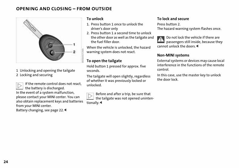
1 Unlocking and opening the tailgate2 Locking and securing
If the remote control does not react,
To unlock1. Press button 1 once to unlock the
driver's door only2. Press button 1 a second time to unlock
the other door as well as the tailgate anthe fuel filler door.
When the vehicle is unlocked, the hazard warning system does not react.
To open the tailgateHold button 1 pressed for approx. five seconds.
The tailgate will open slightly, regardless of whether it was previously locked or unlocked.
the battery is discharged.In the event of a system malfunction, please contact your MINI center. You can also obtain replacement keys and batteries from your MINI center.Battery changing, see page 22.<
Before and after a trip, be sure that the tailgate was not opened uninten
tionally.<
OV
ERV
IEW
REP
AIR
SO
PER
ATI
ON
CO
NTR
OLS
TA
OPENING AND CLOSING – FROM OUTSIDE
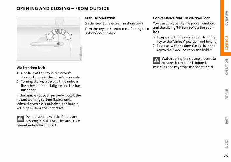
venience feature via door lockcan also operate the power windows the sliding/tilt sunroof via the door
open: with the door closed, turn the y to the "Unlock" position and hold it close: with the door closed, turn the y to the "Lock" position and hold it.
Watch during the closing process to be sure that no one is injured. sing the key stops the operation.<
o
ConYou and lock.
> Toke
> Toke
Relea
DA
IND
EX
25
Via the door lock1. One turn of the key in the driver's
door lock unlocks the driver’s door only2. Turning the key a second time unlocks
Manual operation (in the event of electrical malfunction)
Turn the key to the extreme left or right tunlock/lock the door.
the other door, the tailgate and the fuel filler door.
If the vehicle has been properly locked, the hazard warning system flashes once.When the vehicle is unlocked, the hazard warning system does not react.
Do not lock the vehicle if there are passengers still inside, because they
cannot unlock the doors.<
26
OPENING AND CLOSING – FROM INSIDE
ck the switch for the central locking
m
the individual safety lock buttons .
Children might be able to lock the doors from the inside. Always take hicle's keys with you so that you can
the vehicle again from the outside at ime.<
o
n.
To loTouchsyste
or
pressdown
the veopenany t
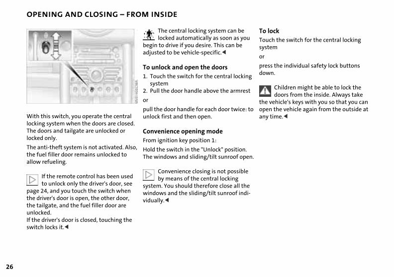
With this switch, you operate the centrallocking system when the doors are closed. The doors and tailgate are unlocked or locked only.
The central locking system can be locked automatically as soon as you
begin to drive if you desire. This can be adjusted to be vehicle-specific.<
To unlock and open the doors1. Touch the switch for the central locking
system2. Pull the door handle above the armrest
or
pull the door handle for each door twice: tunlock first and then open.
Convenience opening modeFrom ignition key position 1:
The anti-theft system is not activated. Also, the fuel filler door remains unlocked to allow refueling.
If the remote control has been used to unlock only the driver's door, see
page 24, and you touch the switch when the driver's door is open, the other door, the tailgate, and the fuel filler door are unlocked. If the driver's door is closed, touching the switch locks it.<
Hold the switch in the "Unlock" position.The windows and sliding/tilt sunroof ope
Convenience closing is not possible by means of the central locking
system. You should therefore close all thewindows and the sliding/tilt sunroof indi-vidually.<
OV
ERV
IEW
REP
AIR
SO
PER
ATI
ON
CO
NTR
OLS
TAILGATE
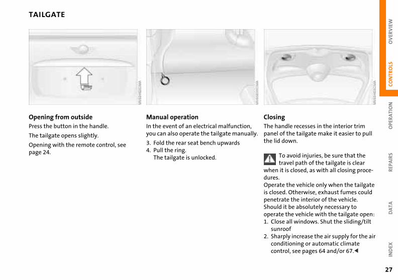
ingandle recesses in the interior trim
l of the tailgate make it easier to pull id down.
To avoid injuries, be sure that the travel path of the tailgate is clear
n it is closed, as with all closing proce-s.ate the vehicle only when the tailgate sed. Otherwise, exhaust fumes could
ly.
ClosThe hpanethe l
whedureOperis clo
DA
TAIN
DEX
trate the interior of the vehicle.ld it be absolutely necessary to
ate the vehicle with the tailgate open:ose all windows. Shut the sliding/tilt nroofarply increase the air supply for the air nditioning or automatic climate ntrol, see pages 64 and/or 67.<
peneShouoper1. Cl
su2. Sh
coco
27
Opening from outsidePress the button in the handle.
The tailgate opens slightly.
Opening with the remote control, see
Manual operationIn the event of an electrical malfunction,you can also operate the tailgate manual
3. Fold the rear seat bench upwards
page 24. 4. Pull the ring.The tailgate is unlocked.
28
ELECTRIC POWER WINDOWS
the ignition has been switched off:
an use the electric power windows as s no one opens any of the doors. or is opened during operation, the
ing/closing process stops immedi-
When leaving the vehicle, always remove the ignition key from the nd remember to close the doors to nt children from operating the power
ows and injuring themselves, etc.<
e convenience mode via the door refer to page 25.
-
After
You clong aIf a doopenately.
lock aprevewind
For thlock,
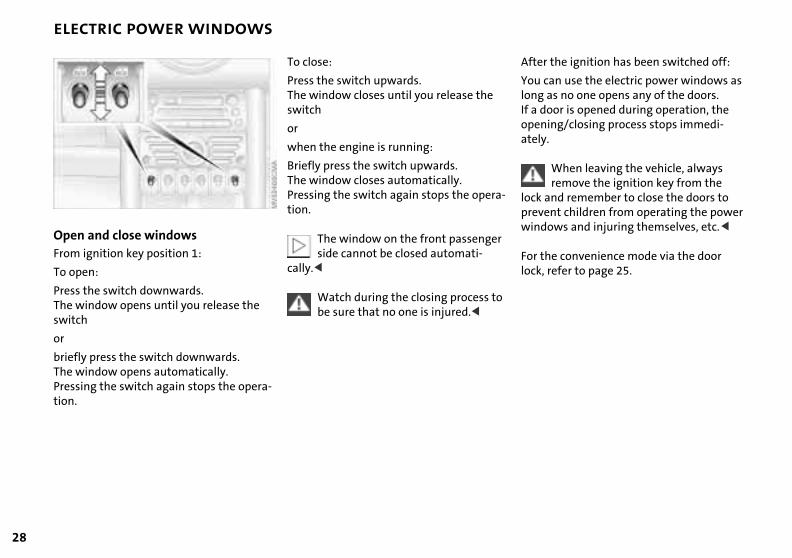
Open and close windowsFrom ignition key position 1:
To open:
To close:
Press the switch upwards.The window closes until you release the switch
or
when the engine is running:
Briefly press the switch upwards.The window closes automatically.Pressing the switch again stops the operation.
The window on the front passengerside cannot be closed automati-
cally.<
Press the switch downwards.The window opens until you release the switch
or
briefly press the switch downwards.The window opens automatically. Pressing the switch again stops the opera-tion.
Watch during the closing process tobe sure that no one is injured.<

OV
ERV
IEW
OPE
RA
TIO
NC
ON
TRO
LS
SLIDING/TILT SUNROOF*
Do not use force to close the sliding/tilt sunroof in its raised position, as
age to the mechanism could result.<
the ignition has been switched off:
an still operate the sliding/tilt sunroof p to one minute, as long as no one s any of the doors.oor is opened during operation, the ing/closing stops immediately.
matic opening and closingen:
the switch past the resistance point: unroof opens completely
dam
After
You cfor uopenIf a dopen
AutoTo op
PushThe s
REP
AIR
SD
ATA
IND
EX
ose:
sh the switch past the resistance int: e sunroof closes to the raised positionsh the switch again: e sunroof closes completely.
hing the switch briefly during opening sing stops the movement immedi-
.
n is
To cl
1. PupoTh
2. PuTh
Toucor cloately
29
To prevent injuries, exercise care when closing the sliding/tilt sunroof
and keep it in your field of vision until it is shut.When leaving the vehicle, always remove the ignition key from the lock and remember to close the doors to prevent children from operating the sunroof and injuring themselves, etc. Be sure that adequate clearance is main-tained for the opening path of the sliding/tilt sunroof, otherwise damage can occur.<
For the convenience mode via the door lock, refer to page 25.
Raising – Opening – ClosingFrom ignition key position 1:
To raise:
Press the switchor
push the switch backwards to the resis-tance point.
Opening and closing1. Push the switch in the desired directio
until you feel resistance and hold in thposition
2. Release the switch when the desired position has been reached.

30
SLIDING/TILT SUNROOF* ROLLER SUN BLIND*
eningss the button in the handle, see ow 1.e cap is unlocked
1 Op1. Pre
arrTh
ide the roller sun blind towards the ck.
singe the handle to pull the roller sun nd forwardsgage the handle in the device, see ow 2.
/
2. Guba
2 Clo1. Us
bli2. En
arr
Safety featureAs of approximately the middle of the roof opening, if the sliding/tilt sunroof encoun-ters resistance during closing, the closing operation is interrupted and the sunroof opens again slightly.
Despite this safety feature, be extremely careful that the closing
path of the sunroof is not obstructed when-ever it is closed. Otherwise, triggering the closing-force limitation may not be ensured in some situations (with very thin objects, for instance).You can override this safety feature by pressing the switch beyond the resistance
Manual opening and closingIn the event of an electrical malfunction, you can also operate the sliding/tilt sunroof manually:
point and holding it.< 1. Push the clock towards the interior andremove
2 Use an Allen wrench to turn the slidingtilt sunroof in the desired direction.
OV
ERV
IEW
OPE
RA
TIO
NC
ON
TRO
LS
CORRECT SITTING POSTURE SEAT ADJUSTMENT
ortant adjustment informationNever try to adjust your seat while operating the vehicle. The seat could nd with an unexpected movement,
the ensuing loss of vehicle control lead to an accident.r ride with the backrest reclined to an me horizontal angle (especially impor-for front passengers to remember). the backrest relatively upright to mize the risk of sliding under the y belt and sustaining injury in an acci-.<
sting the seats, see next page.
to w
t
ts
Imp
respoand couldNeveextretant Keepminisafetdent
Adju
REP
AIR
SD
ATA
IND
EX
e -
.
it -
,
31
The ideal seating position can make a vital contribution to relaxed, fatigue-free driving. The correct seating position also works together with the safety belts and airbags to provide occupants with maximum levels of passive safety in an accident. To ensure that the safety systems operate with optimal efficiency, we strongly urge you to observe the instruc-tions contained in the following section.
For supplementary information on trans-porting children, refer to page 38.
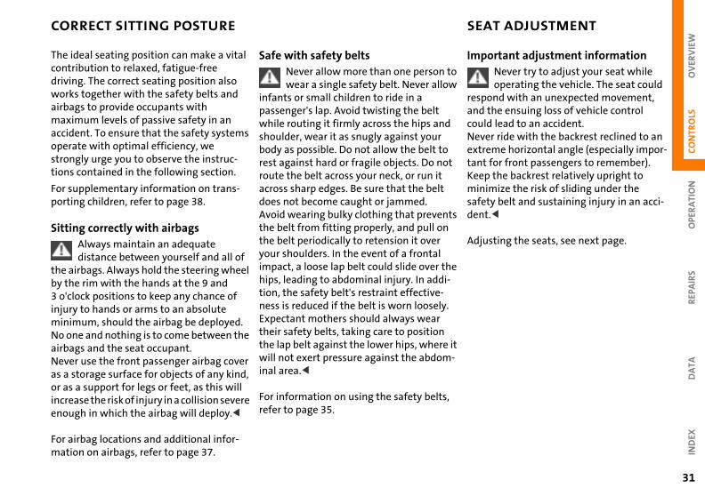
Sitting correctly with airbagsAlways maintain an adequate distance between yourself and all of
Safe with safety beltsNever allow more than one person wear a single safety belt. Never allo
infants or small children to ride in a passenger's lap. Avoid twisting the belt while routing it firmly across the hips andshoulder, wear it as snugly against your body as possible. Do not allow the belt torest against hard or fragile objects. Do noroute the belt across your neck, or run it across sharp edges. Be sure that the belt does not become caught or jammed.Avoid wearing bulky clothing that preventhe belt from fitting properly, and pull onthe belt periodically to retension it over your shoulders. In the event of a frontal
the airbags. Always hold the steering wheel by the rim with the hands at the 9 and 3 o'clock positions to keep any chance of injury to hands or arms to an absolute minimum, should the airbag be deployed. No one and nothing is to come between the airbags and the seat occupant.Never use the front passenger airbag cover as a storage surface for objects of any kind, or as a support for legs or feet, as this will increase the risk of injury in a collision severe enough in which the airbag will deploy.<
For airbag locations and additional infor-mation on airbags, refer to page 37.
impact, a loose lap belt could slide over thhips, leading to abdominal injury. In addition, the safety belt's restraint effective-ness is reduced if the belt is worn looselyExpectant mothers should always wear their safety belts, taking care to position the lap belt against the lower hips, wherewill not exert pressure against the abdominal area.<
For information on using the safety beltsrefer to page 35.
32
SEAT ADJUSTMENT
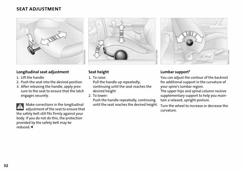
ar support* an adjust the contour of the backrest ditional support in the curvature of
spine's lumbar region.
LumbYou cfor adyour
pper hips and spinal column receive ementary support to help you main- relaxed, upright posture.
the wheel to increase or decrease the ture.
t.
The usuppltain a
Turn curva
Longitudinal seat adjustment 1. Lift the handle 2. Push the seat into the desired position3. After releasing the handle, apply pres-
Seat height 1. To raise:
Pull the handle up repeatedly, continuing until the seat reaches the
sure to the seat to ensure that the latch engages securely.
Make corrections in the longitudinal adjustment of the seat to ensure that
the safety belt still fits firmly against your body. If you do not do this, the protection provided by the safety belt may be reduced.<
desired height2. To lower:
Push the handle repeatedly, continuinguntil the seat reaches the desired heigh
OV
ERV
IEW
OPE
RA
TIO
NC
ON
TRO
LS
SEAT ADJUSTMENT ENTRY TO THE REAR
When returning the seat to the rear position, ensure that no one is
ed and that no objects are damaged. ge and lock both seats and backrests position prior to driving, otherwise pected movement could increase the f accident.<
at
injurEngainto unexrisk o
REP
AIR
SD
ATA
IND
EX
si-
33
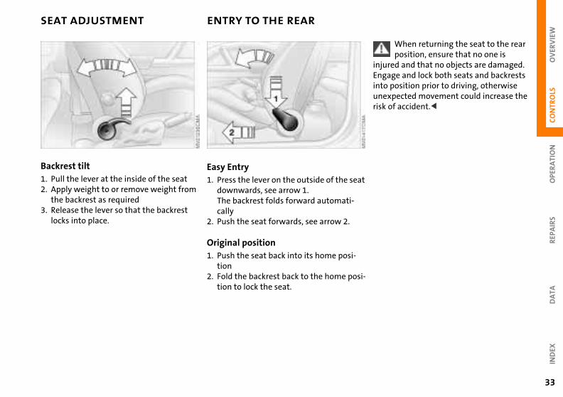
Backrest tilt 1. Pull the lever at the inside of the seat2. Apply weight to or remove weight from
the backrest as required
Easy Entry1. Press the lever on the outside of the se
downwards, see arrow 1.The backrest folds forward automati-
3. Release the lever so that the backrest locks into place.
cally2. Push the seat forwards, see arrow 2.
Original position1. Push the seat back into its home posi-
tion2. Fold the backrest back to the home po
tion to lock the seat.
34
HEATED SEATS* HEAD RESTRAINTS
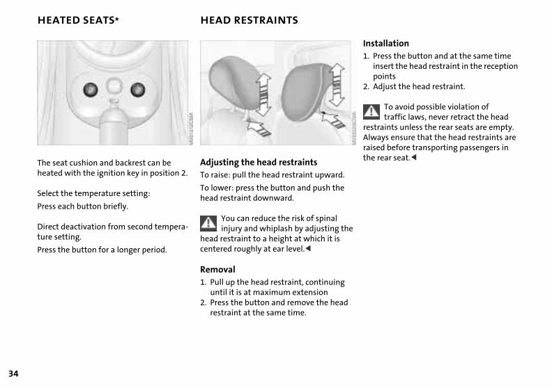
llationss the button and at the same time ert the head restraint in the reception intsjust the head restraint.
To avoid possible violation of traffic laws, never retract the head ints unless the rear seats are empty.
ys ensure that the head restraints are before transporting passengers in ar seat.<
Insta1. Pre
inspo
2. Ad
restraAlwaraisedthe re
e
The seat cushion and backrest can be heated with the ignition key in position 2.
Select the temperature setting:
Adjusting the head restraintsTo raise: pull the head restraint upward.
To lower: press the button and push the head restraint downward.
Press each button briefly.
Direct deactivation from second tempera-ture setting.
Press the button for a longer period.
You can reduce the risk of spinal injury and whiplash by adjusting th
head restraint to a height at which it is centered roughly at ear level.<
Removal1. Pull up the head restraint, continuing
until it is at maximum extension2. Press the button and remove the head
restraint at the same time.

OV
ERV
IEW
OPE
RA
TIO
NC
ON
TRO
LS
SAFETY BELTS STEERING WHEEL
djust the steering wheel heightsh the locking lever downwardjust the desired steering wheel sition
To a1. Pu2. Ad
po
REP
AIR
SD
ATA
IND
EX
ll the lever back in.
Do not adjust the steering wheel while the vehicle is moving, other-
unexpected movement could increase isk of accident.<
sh
g
er-
as g
3. Pu
wisethe r
35
Drive with your safety belt onEven though there is an airbag, wear a safety belt every time you get in the vehicle, because airbags enhance safety by
Safety belt height adjustmentUse the height adjustment mechanism toadapt the safety belt to the ideal positionfor your own body:
providing added protection.
To fastenMake sure you hear the lock engage in the belt buckle.
To release1. Press the red button in the belt buckle2. Hold the belt3. Guide the belt back into its reel.
Press the button and at the same time puthe entire unit upwards or downwards.
Also observe the instructions on adjustinthe seats on page 31.
If the safety belts are damaged or stretched in an accident: have the
safety belt system replaced by your MINIcenter and the belt anchors checked, othwise the safety function can no longer beguaranteed. If a child-restraint system win the vehicle during an accident, consultthe manufacturer's instructions regardinreplacement.<
36
MIRRORS
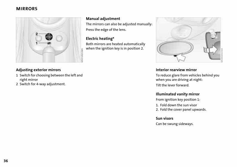
ior rearview mirror uce glare from vehicles behind you
you are driving at night:
e lever forward.
:
InterTo redwhen
Tilt th
inated vanity mirror ignition key position 1:
ld down the sun visorld the cover panel upwards.
isorse swung sideways.
IllumFrom
1. Fo2. Fo
Sun vCan b
Adjusting exterior mirrors1 Switch for choosing between the left and
right mirror2 Switch for 4-way adjustment.
Manual adjustmentThe mirrors can also be adjusted manually
Press the edge of the lens.
Electric heating*Both mirrors are heated automatically when the ignition key is in position 2.

OV
ERV
IEW
OPE
RA
TIO
NC
ON
TRO
LS
MIRRORS AIRBAGS
ned to help support the seat occu-'s upper body.
nformation on sitting posture, refer to 31.
The airbags do not deploy in response to minor collisions, rear impacts and
in kinds of vehicle rollover.<
when all safety guidelines are rved, there is a small residual risk that engers will sustain facial, hand or arm ies in isolated instances. The ignition inflation noise may induce a mild
orary hearing loss in sensitive individ-
desigpant
For ipage
certa
Evenobsepassinjurand tempuals.
REP
AIR
SD
ATA
IND
EX
Do not apply adhesive materials to the cover panels of the airbags, cover or modify them in any other way. Do
it covers, cushions or other items to ront seats that have not been specially oved for seats with side airbags. Do ang clothing, e.g. jackets, over the
rests. Do not attempt to remove the g restraint system from the vehicle. In vent of malfunctions, immobilization e (triggering) of the airbag restraint m in accordance with its intended
tion, only commission a MINI center the inspection, repair or disassembly.
n
themnot fthe fapprnot hbackairbathe eor ussystefuncwith
37
Interior rearview mirror, automatic dimming feature* The mirror dims automatically as required.
The mirror becomes clear again when you
1 Side airbags in seats on the driver and passenger sides (front)
2 Head airbags on the driver and passenger sides for both rows of seats
engage reverse gear or select selector lever position R.
Keep the photocells free and clean to ensure that the mirror functions perfectly.There is one photocell in the mirror frame; the other is on the back of the mirror.
Do not cover the area between the inside rearview mirror and the wind-
shield, and do not place stickers or toll tags on the windshield in front of the mirror.<
(front/rear)
3 Front airbags on the driver and passenger sides
Protective effectThe front airbags supplement the safety belts by helping to provide additional protection for the driver and front passenger in the event of a frontal collisioin which the protection afforded by the belts alone may no longer be sufficient. When needed, the head and side airbagshelp to furnish protection in the event ofside impact. Each of the side airbags is
38
AIRBAGS TRANSPORTING CHILDREN
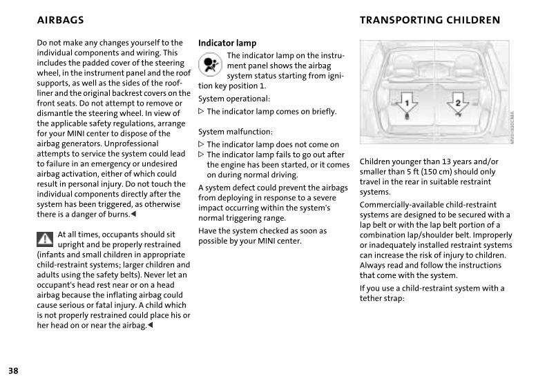
ren younger than 13 years and/or er than 5 ft (150 cm) should only l in the rear in suitable restraint ms.
s
Childsmalltravesyste
ercially-available child-restraint ms are designed to be secured with a lt or with the lap belt portion of a ination lap/shoulder belt. Improperly dequately installed restraint systems crease the risk of injury to children.
ys read and follow the instructions ome with the system.
use a child-restraint system with a r strap:
Commsystelap becombor inacan inAlwathat c
If youtethe
Do not make any changes yourself to the individual components and wiring. This includes the padded cover of the steering wheel, in the instrument panel and the roof supports, as well as the sides of the roof-liner and the original backrest covers on the front seats. Do not attempt to remove or dismantle the steering wheel. In view of the applicable safety regulations, arrange for your MINI center to dispose of the airbag generators. Unprofessional attempts to service the system could lead to failure in an emergency or undesired airbag activation, either of which could result in personal injury. Do not touch the individual components directly after the
Indicator lampThe indicator lamp on the instru-ment panel shows the airbag system status starting from igni-
tion key position 1.
System operational:
> The indicator lamp comes on briefly.
System malfunction:
> The indicator lamp does not come on> The indicator lamp fails to go out after
the engine has been started, or it comeon during normal driving.
A system defect could prevent the airbags
system has been triggered, as otherwise there is a danger of burns.<
At all times, occupants should sit upright and be properly restrained
(infants and small children in appropriate child-restraint systems; larger children and adults using the safety belts). Never let an occupant's head rest near or on a head airbag because the inflating airbag could cause serious or fatal injury. A child which is not properly restrained could place his or her head on or near the airbag.<
from deploying in response to a severe impact occurring within the system's normal triggering range.
Have the system checked as soon as possible by your MINI center.
OV
ERV
IEW
REP
AIR
SO
PER
ATI
ON
CO
NTR
OLS
TRANSPORTING CHILDREN SAFELY
Adjust the tether strap according to the child restraint manufacturer's
uctions. Before installing any child-aint device or child seat, please read ollowing: r install a rearward-facing child-aint system in the front passenger seat is vehicle. vehicle is equipped with an airbag lemental restraint system for the front enger. Because the backrest on any
ard-facing child-restraint system – e kind designed for infants under r and 20 Ibs./9 kg – would be within irbag's deployment range, you should r mount such a device in the front enger seat, since the impact of the g against the child restraint's backrest lead to serious or fatal injuries.
s necessary for a child – not an infant – e in the front seat, certain precautions
to
instrrestrthe fNeverestrof thYoursupppassrearwof th1 yeathe anevepassairbacouldIf it ito rid
DA
TAIN
DEX
ld be taken. First, move the passenger as far away from the instrument panel ssible. This important precaution is ded to maximize the distance een the airbag and the child. Older ren should be tightly secured with a y belt, after they have outgrown a ter seat that is appropriate for their height and weight. Younger children ld be secured in an appropriate
shouseat as pointenbetwchildsafetboosage, shou
39
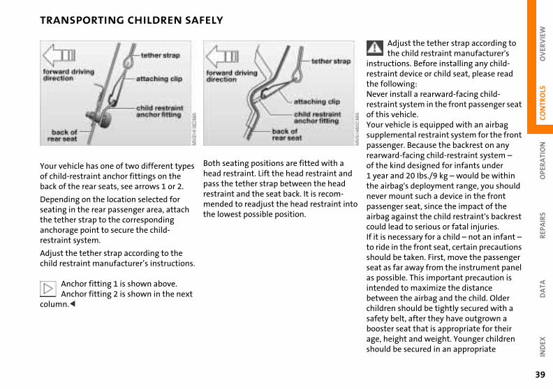
Your vehicle has one of two different types of child-restraint anchor fittings on the back of the rear seats, see arrows 1 or 2.
Depending on the location selected for
Both seating positions are fitted with a head restraint. Lift the head restraint andpass the tether strap between the head restraint and the seat back. It is recom-
seating in the rear passenger area, attach the tether strap to the corresponding anchorage point to secure the child-restraint system.
Adjust the tether strap according to the child restraint manufacturer’s instructions.
Anchor fitting 1 is shown above.Anchor fitting 2 is shown in the next
column.<
mended to readjust the head restraint inthe lowest possible position.
40
TRANSPORTING CHILDREN SAFELY
ck the belt he entire length of the belt from the etractor. Allow the reel to retract the omewhat and engage the buckle, tighten the belt against the child-int system. The retraction mecha-is now locked.
lock the belt se the buckle, remove the child-int system and allow the belt tor to reel the belt completely in.
To loPull tbelt rbelt sthen restranism
To unRelearestraretrac
forward-facing child-restraint system that has first been properly secured with a safety belt. Never install a rearward-facing child-restraint system in the front passenger seat. We strongly urge you to carefully read and comply with the instructions for installa-tion and use provided by the child restraint's manufacturer whenever you use such a device.Be sure that all occupants – of all ages – remain properly and securely restrained at all times.According to accident statistics, children are safer when properly restrained in the rear seats than in the front seating posi-
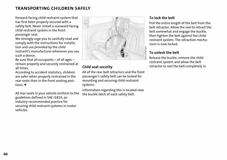
Child seat securityAll of the rear belt retractors and the frontpassenger's safety belt can be locked for mounting and securing child-restraint
tions.<
All rear seats in your vehicle conform to the guidelines defined in SAE J1819, an industry recommended practice for securing child-restraint systems in motor vehicles.
systems.
Information regarding this is located nearthe buckle latch of each safety belt.
OV
ERV
IEW
OPE
RA
TIO
NC
ON
TRO
LS
TRANSPORTING CHILDREN VEHICLE MEMORY
tomatic activation of windshield pers on cleaningollow me home" lampsw beams light up for a short time after e engine has been switched offcking when engine is running (with cond key)op function of power windows on ening/closingtivating/deactivating daytime driving
ps*itching on interior lamps via remote
ntrol.
This symbol draws your attention to other Vehicle Memory functions
w
s .
ns
> Auwi
> "FLoth
> Lose
> Stop
> Aclam
> Swco
REP
AIR
SD
ATA
IND
EX
ribed in the Owner's Manual.<
ilt
desc
41
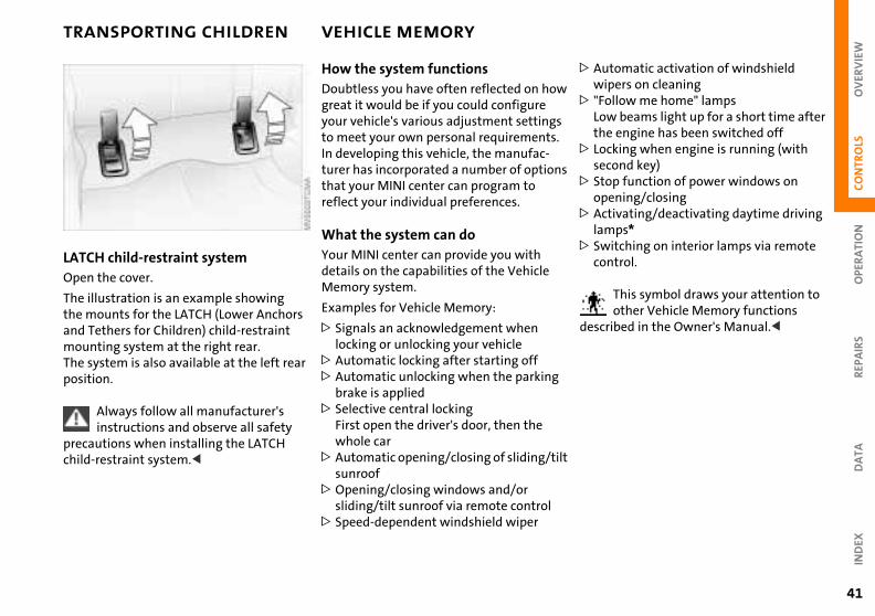
LATCH child-restraint systemOpen the cover.
The illustration is an example showing the mounts for the LATCH (Lower Anchors
How the system functionsDoubtless you have often reflected on hogreat it would be if you could configure your vehicle's various adjustment settingto meet your own personal requirementsIn developing this vehicle, the manufac-turer has incorporated a number of optiothat your MINI center can program to reflect your individual preferences.
What the system can doYour MINI center can provide you with details on the capabilities of the Vehicle Memory system.
Examples for Vehicle Memory:
and Tethers for Children) child-restraint mounting system at the right rear. The system is also available at the left rear position.
Always follow all manufacturer's instructions and observe all safety
precautions when installing the LATCH child-restraint system.<
> Signals an acknowledgement when locking or unlocking your vehicle
> Automatic locking after starting off> Automatic unlocking when the parking
brake is applied> Selective central locking
First open the driver's door, then the whole car
> Automatic opening/closing of sliding/tsunroof
>Opening/closing windows and/or sliding/tilt sunroof via remote control
> Speed-dependent windshield wiper
42
IGNITION LOCK STARTING THE ENGINE
t allow the engine to warm up with hicle at a standstill. Move off imme-
ly at a moderate engine speed.
Do not allow the engine to run in enclosed spaces. The exhaust gases in carbon monoxide, an odorless and ess, but highly toxic gas. hing the exhaust gases poses an me health risk, and can lead to uncon-sness and death.t leave the vehicle unattended with
ngine running. An unattended vehicle a running engine represents a poten-fety hazard. When driving, standing or when parking, take precautions to
.
e
Do nothe vediate
contacolorlBreatextresciouDo nothe ewith tial saat idle
contact between the hot exhaust m and easily flammable materials , hay or leaves, for example). Such ct could lead to a fire, resulting in s personal injury and property ge.<
r-
e
avoidsyste(grasscontaserioudama
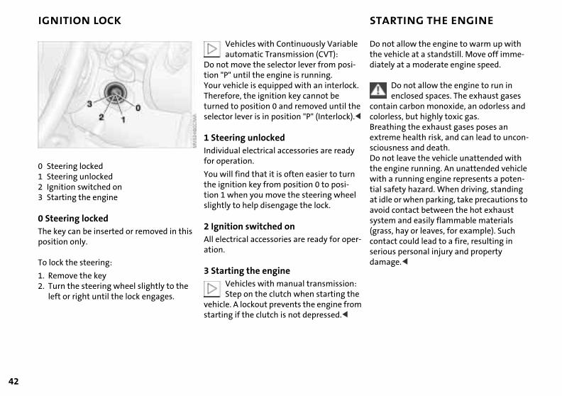
0 Steering locked 1 Steering unlocked2 Ignition switched on3 Starting the engine
Vehicles with Continuously Variableautomatic Transmission (CVT):
Do not move the selector lever from posi-tion "P" until the engine is running.Your vehicle is equipped with an interlockTherefore, the ignition key cannot be turned to position 0 and removed until thselector lever is in position "P" (Interlock).<
1 Steering unlocked Individual electrical accessories are ready for operation.
You will find that it is often easier to turnthe ignition key from position 0 to posi-tion 1 when you move the steering wheel
0 Steering locked The key can be inserted or removed in this position only.
To lock the steering:
1. Remove the key2. Turn the steering wheel slightly to the
left or right until the lock engages.
slightly to help disengage the lock.
2 Ignition switched onAll electrical accessories are ready for opeation.
3 Starting the engineVehicles with manual transmission:Step on the clutch when starting th
vehicle. A lockout prevents the engine fromstarting if the clutch is not depressed.<
OV
ERV
IEW
OPE
RA
TIO
NC
ON
TRO
LS
STARTING THE ENGINE SWITCHING OFF THE ENGINE
You should never remove the ignition key when the vehicle is in motion, as
teering lock could engage.n you leave the vehicle, always remove gnition key and engage the steering
n you park on downward slopes, ge the parking brake.<
ual transmission the ignition key to position 1 or 0.
tinuously Variable automatic smission (CVT)*ge selector lever position P, turn the ion key to position 1 or 0.
ral
N re
the sWhethe ilock.Wheenga
ManTurn
ConTranEngaignit
REP
AIR
SD
ATA
IND
EX
43
StartingWhen starting the engine, do not press the accelerator pedal.
Do not actuate the starter for too short a time. Do not turn it for more
than approx. 20 seconds. Release the igni-tion key immediately when the engine starts.Extended starting attempts, characterized by excessively frequent or long periods with the starter engaged, can lead to damage in the catalytic converter.<
If the engine does not start on the first attempt (the engine is very hot or cold, for
Manual transmission1. Engage the parking brake2. Put the manual gearshift lever in neut3. Press the clutch pedal4. Start the engine.
Continuously Variable automatic Transmission (CVT)*1. Press the footbrake2. Put the selector lever in position P or N3. Starting the engine.
Move the selector lever to position and engage the parking brake befo
leaving your vehicle with the engine running.
instance):
> Press the accelerator pedal halfway down while engaging the starter.
Cold starts at extremely low temperatures (as of approx. +5 7(–15 6)):
> Press the accelerator pedal halfway down while engaging the starter
> For the initial start attempt, allow the starter to remain engaged somewhat longer (approx. 10 seconds).
Do not leave the vehicle with the engine running. An unattended vehicle with a running engine represents a potential safety hazard.<
44
PARKING BRAKE
g r
e
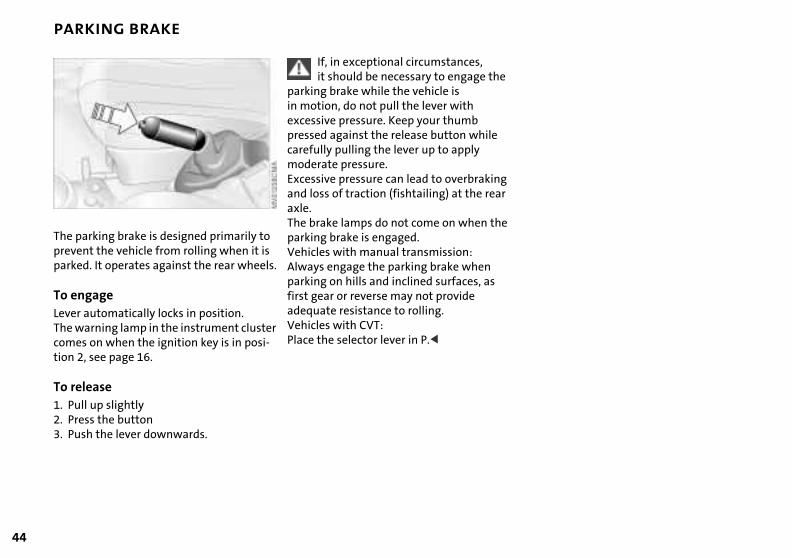
The parking brake is designed primarily to prevent the vehicle from rolling when it is parked. It operates against the rear wheels.If, in exceptional circumstances, it should be necessary to engage the
parking brake while the vehicle is in motion, do not pull the lever with excessive pressure. Keep your thumb pressed against the release button while carefully pulling the lever up to apply moderate pressure.Excessive pressure can lead to overbrakinand loss of traction (fishtailing) at the reaaxle.The brake lamps do not come on when thparking brake is engaged.Vehicles with manual transmission:Always engage the parking brake when parking on hills and inclined surfaces, as
To engageLever automatically locks in position. The warning lamp in the instrument cluster comes on when the ignition key is in posi-tion 2, see page 16.
To release1. Pull up slightly2. Press the button3. Push the lever downwards.
first gear or reverse may not provide adequate resistance to rolling.Vehicles with CVT:Place the selector lever in P.<
OV
ERV
IEW
OPE
RA
TIO
NC
ON
TRO
LS
MANUAL TRANSMISSION
to
r-
REP
AIR
SD
ATA
IND
EX
45
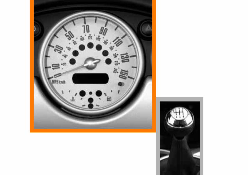
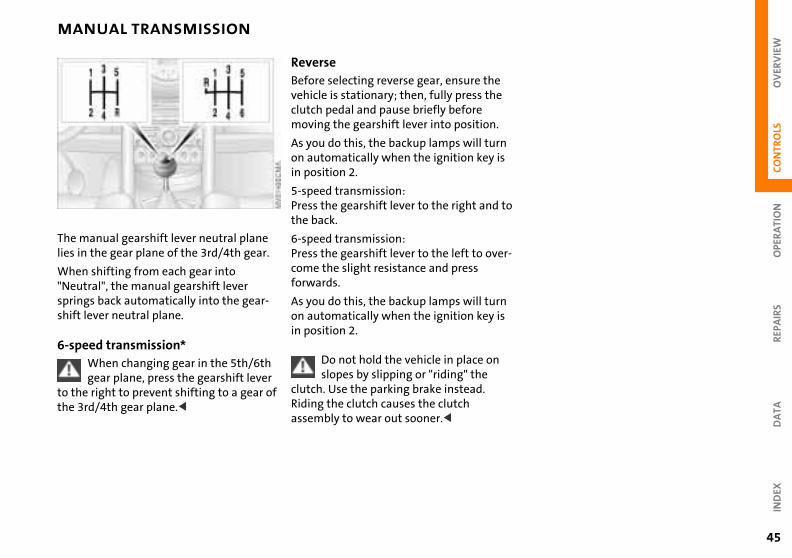
The manual gearshift lever neutral plane lies in the gear plane of the 3rd/4th gear.
When shifting from each gear into "Neutral", the manual gearshift lever
Reverse Before selecting reverse gear, ensure thevehicle is stationary; then, fully press theclutch pedal and pause briefly before moving the gearshift lever into position.
As you do this, the backup lamps will turnon automatically when the ignition key isin position 2.
5-speed transmission:Press the gearshift lever to the right and the back.
6-speed transmission:Press the gearshift lever to the left to ovecome the slight resistance and press forwards.
springs back automatically into the gear-shift lever neutral plane.
6-speed transmission*When changing gear in the 5th/6th gear plane, press the gearshift lever
to the right to prevent shifting to a gear of the 3rd/4th gear plane.<
As you do this, the backup lamps will turnon automatically when the ignition key isin position 2.
Do not hold the vehicle in place on slopes by slipping or "riding" the
clutch. Use the parking brake instead. Riding the clutch causes the clutch assembly to wear out sooner.<
46
CONTINUOUSLY VARIABLE AUTOMATIC TRANSMISSION (CVT)*
While the vehicle is stationary and before shifting out of P or N, press
rake pedal in order to disengage the tor lever lock mechanism (Shiftlock). engine speed is too high when the le is at a standstill, the selector lever o blocked to protect the transmission. the brake pedal down until starting therwise the vehicle will "creep" when
ve position is engaged.<
To prevent the vehicle from starting off on its own, always move the
tor lever to position P or N and engage arking brake before leaving your le with the engine running.
ot leave the vehicle unattended with ngine running. An unattended vehicle a running engine represents a poten-afety hazard.<
If the selector lever is not placed in position P when the vehicle is parked,
osition display of the selector lever on. This can lead to battery arge.<
the bselecIf thevehicis alsHoldoff. Oa dri
selecthe pvehicDo nthe ewithtial s
the pstaysdisch
You can drive with a steplessly shifting CVT. In addition, you can also shift manually.
When you move the selector lever from the D position to the right into the M/S + –range, the performance-oriented shift programs of the CVT are engaged. Step-tronic enters the manual selection mode and executes the desired shift whenever you tap the selector lever in the direction indicated by "+" or "–" .
Whenever you want to use automatic again, just move the selector lever toward the left to position D.
In positition D, you achieve the lowest fuel consumption for average
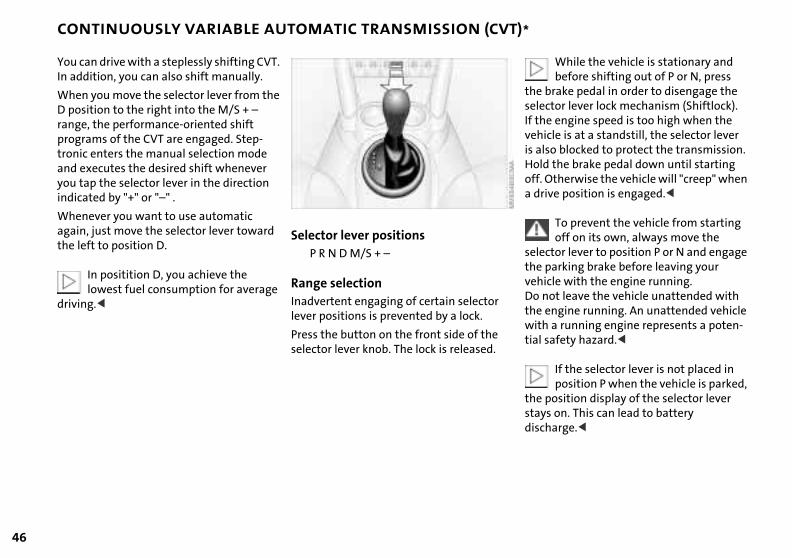
Selector lever positionsP R N D M/S + –
Range selection
driving.< Inadvertent engaging of certain selector lever positions is prevented by a lock.
Press the button on the front side of the selector lever knob. The lock is released.
OV
ERV
IEW
REP
AIR
SO
PER
ATI
ON
CO
NTR
OLS
DA
TAIN
DEX
CONTINUOUSLY VARIABLE AUTOMATIC TRANSMISSION (CVT)*
ransmission will only execute upshifts ownshifts that will result in a plau-combination of vehicle speed and e rpm, forinstance, downshifts that
d result in excessive engine speed are xecuted.
hing from M/S + – into the selector positions P, R and N and switching manual mode back into the Sport am is only possible via D.
e
The tand dsible enginwoulnot e
Switclever from progr
47
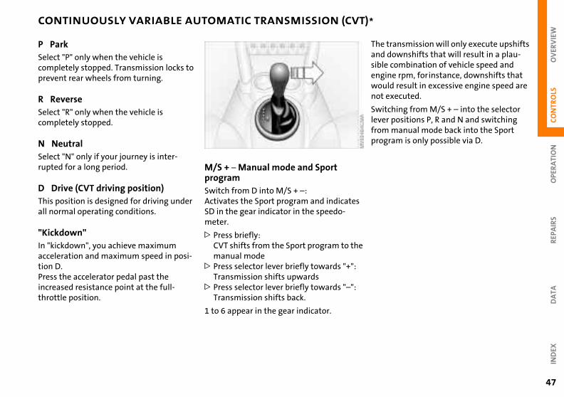
P ParkSelect "P" only when the vehicle is completely stopped. Transmission locks to prevent rear wheels from turning.
R ReverseSelect "R" only when the vehicle is completely stopped.
N NeutralSelect "N" only if your journey is inter-rupted for a long period.
D Drive (CVT driving position)This position is designed for driving under
M/S + – Manual mode and Sport programSwitch from D into M/S + –:Activates the Sport program and indicates
all normal operating conditions.
"Kickdown"In "kickdown", you achieve maximum acceleration and maximum speed in posi-tion D.Press the accelerator pedal past the increased resistance point at the full-throttle position.
SD in the gear indicator in the speedo-meter.
> Press briefly:CVT shifts from the Sport program to thmanual mode
> Press selector lever briefly towards "+":Transmission shifts upwards
> Press selector lever briefly towards "–":Transmission shifts back.
1 to 6 appear in the gear indicator.
48
CONTINUOUSLY VARIABLE AUTOMATIC TRANSMISSION (CVT)*
-r
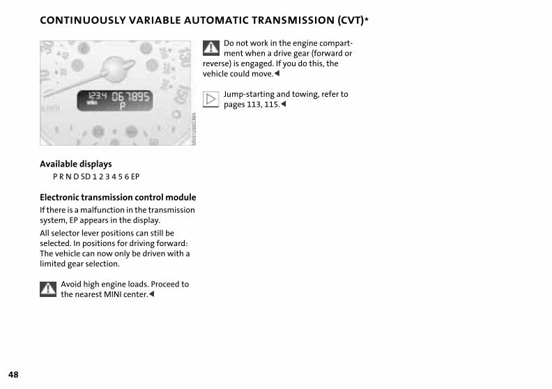
Available displays P R N D SD 1 2 3 4 5 6 EP
Electronic transmission control module
Do not work in the engine compartment when a drive gear (forward o
reverse) is engaged. If you do this, the vehicle could move.<
Jump-starting and towing, refer to pages 113, 115.<
If there is a malfunction in the transmission system, EP appears in the display.
All selector lever positions can still be selected. In positions for driving forward: The vehicle can now only be driven with a limited gear selection.
Avoid high engine loads. Proceed to the nearest MINI center.<

OV
ERV
IEW
SO
PER
ATI
ON
CO
NTR
OLS
PARKING LAMPS/LOW BEAMS SIGNAL/HEADLAMP FLASHER
rn signal indicator (green indicator companied by periodic clicking sound m the relay)
gh beams/Headlamp flasher (blue dicator lamp)
i-
e
al
d tic u
1 Tuacfro
2 Hiin
REP
AIR
DA
TAIN
DEX
ignal briefly the lever up to but not beyond the
nt.
If the indicator lamp of the indicators and the clicking from the relay are
faster than normal: one of the turn l indicators has failed.<
n To sPressdete
bothsigna
49
Switching on the parking lampsTurn to the first position.The front, rear and side vehicle lighting is switched on.
You can also have this function actvated.<
Switching on the standing lampsFor parking, you can activate lights on onside of the vehicle (observe local laws).
In ignition key position 0:
Move the lever into the relevant turn signindicator position.
"Lights on" warningIf the lights have not been switched off anthe ignition key is in position 0, an acoussignal sounds for a few seconds when yoopen the driver's door to remind you that
One-sided standing lamps, see next column.
Switching on the low beamsTurn to the second position.With the low beams on and with the igni-tion switched off, only the parking lamps will remain on.
"Follow me home" lampsIf you switch off the engine with the low beams on, and then switch off the low beams, they remain lit for approx. one minute.
the lights have not been switched off.
Daytime driving lamps*If you desire, the light switch can be left ithe second position: When the ignition is switched off, the external lighting is also switched off.
You can have this function set by your MINI center.<
50
INSTRUMENT LIGHTING FOG LAMPS INTERIOR LAMPS
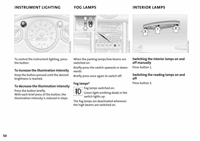
ching the interior lamps on and anually
button 1.
-Switoff mPress
ching the reading lamps on and
button 2.
SwitoffPress
To control the instrument lighting, press the button.
To increase the illumination intensity
When the parking lamps/low beams are switched on:
Briefly press the switch upwards or downwards.
Keep the button pressed until the desired brightness is reached.
To decrease the illumination intensityPress the button briefly.With each brief press of the button, the illumination intensity is reduced in steps.
Briefly press once again to switch off.
Fog lamps*Fog lamps switched on:
Green light-emitting diode in theswitch lights up.
The fog lamps are deactivated wheneverthe high beams are switched on.
OV
ERV
IEW
OPE
RA
TIO
NC
ON
TRO
LS
LIGHT-EMITTING DIODES WASHER/WIPER SYSTEM
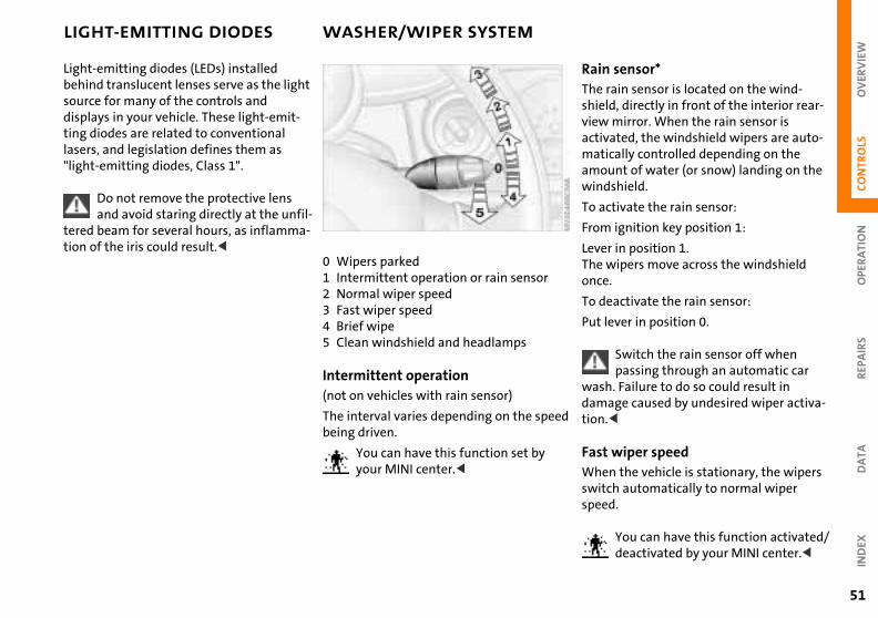
sensor*ain sensor is located on the wind-d, directly in front of the interior rear- mirror. When the rain sensor is ated, the windshield wipers are auto-cally controlled depending on the unt of water (or snow) landing on the shield.
tivate the rain sensor:
ignition key position 1:
r in position 1. ipers move across the windshield
.
activate the rain sensor:
RainThe rshielviewactivmatiamowind
To ac
From
LeveThe wonce
To de
REP
AIR
SD
ATA
IND
EX
ever in position 0.
Switch the rain sensor off when passing through an automatic car . Failure to do so could result in
age caused by undesired wiper activa-<
wiper speedn the vehicle is stationary, the wipers ch automatically to normal wiper d.
You can have this function activated/deactivated by your MINI center.<
ed
Put l
washdamtion.
FastWheswitspee
51
Light-emitting diodes (LEDs) installed behind translucent lenses serve as the light source for many of the controls and displays in your vehicle. These light-emit-ting diodes are related to conventional lasers, and legislation defines them as "light-emitting diodes, Class 1".
Do not remove the protective lens and avoid staring directly at the unfil-
tered beam for several hours, as inflamma-tion of the iris could result.<
0 Wipers parked1 Intermittent operation or rain sensor2 Normal wiper speed3 Fast wiper speed
4 Brief wipe5 Clean windshield and headlampsIntermittent operation(not on vehicles with rain sensor)
The interval varies depending on the spebeing driven.
You can have this function set by your MINI center.<
52
WASHER/WIPER SYSTEM
he
Cleaning windshield and headlamps* The system sprays washer fluid against the windshield. The wipers are automatically activated for a brief period.
When the vehicle lighting is on, the head-lamps are also cleaned at appropriate inter-vals.
Do not use the washers if there is any danger that the fluid will freeze on
the windshield. If you do so, your vision could be obscured. For this reason, use an antifreeze agent, see page 89.Do not use the washers when the reservoir is empty, since this could cause damage to the washing pump.<
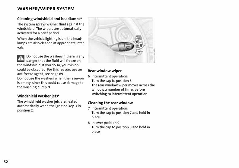
Rear window wiper6 Intermittent operation:
Turn the cap to position 6The rear window wiper moves across t
Windshield washer jets*The windshield washer jets are heated automatically when the ignition key is in position 2.
window a number of times before switching to intermittent operation
Cleaning the rear window7 Intermittent operation:
Turn the cap to position 7 and hold in place
8 In lever position 0:Turn the cap to position 8 and hold in place

OV
ERV
IEW
REP
AIR
SO
PER
ATI
ON
CO
NTR
OLS
CRUISE CONTROL*
ecelerate button 4.
u are already driving with active cruise rol, the speed is decreased by approx. h (2 km/h) every time you briefly tap utton.
and hold button 4.
the cruise control active, the system matically reduces the throttle opening w the vehicle. When you release the
on, the system maintains and stores urrent speed.
x.
on
e
To dPress
If yocont1 mpthe b
Press
Withautoto slobuttthe c
DA
TAIN
DEX
53
Starting at about 25 mph (40 km/h), the vehicle maintains and stores any vehicle speed that you specify.
To activate the system From ignition key position 1:
Press button 2.
The indicator lamp in the instrument cluster lights up.Cruise control is active.
To maintain and store speed or to acceleratePress button 3.
The system maintains and stores the current vehicle speed. Every time you tapthe button, the speed increases by appro1 mph (2 km/h).
Do not use cruise control on twisting roads, when high traffic density
prevents driving at a constant speed, when the road surface is slick (snow, rain, ice), or when the road surface is loose (rocks, sand).<
Press and hold button 3.
The vehicle accelerates without pressure the accelerator pedal. When you release the button, the system maintains and stores the current speed.
If, on a downhill gradient, the enginbraking effect is not sufficient, the
controlled speed may be exceeded. Speedcan drop on uphill grades if the engine output is insufficient.<
54
CRUISE CONTROL*
d
To cancel the cruise control When the system is activated, press button 2.
The indicator lamp stays lit. You can use the cruise control again as required.
In addition, cruise control is canceled auto-matically
> if the brakes are applied>when you apply pressure to the clutch
pedal, or when you move the CVT selector lever from D to P, N or R
> or if the cruise speed is either exceeded or not met for an extended length of time (if you press the accelerator pedal
To continue cruise controlPress button 1.
The vehicle accelerates to and maintains the last speed stored. If you turn the igni-tion key to position 0, the stored speed is deleted and the system is deactivated.
To deactivate the systemWith cancelled cruise control, press button 2 once again.
The indicator lamp goes out and the storespeed is deleted.
and exceed the stored speed, for example).
OV
ERV
IEW
OPE
RA
TIO
NC
ON
TRO
LS
ODOMETER TACHOMETER FUEL GAUGE
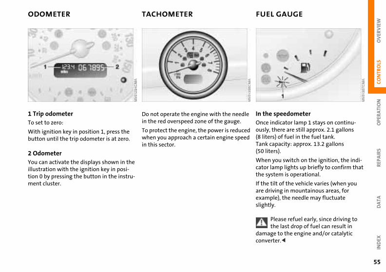
e speedometer indicator lamp 1 stays on continu-, there are still approx. 2.1 gallons
ers) of fuel in the fuel tank.
le
ed d
In thOnceously(8 lit
REP
AIR
SD
ATA
IND
EX
capacity: approx. 13.2 gallons iters).
n you switch on the ignition, the indi-r lamp lights up briefly to confirm that ystem is operational.
tilt of the vehicle varies (when you riving in mountainous areas, for ple), the needle may fluctuate
tly.
Please refuel early, since driving to the last drop of fuel can result in
age to the engine and/or catalytic erter.<
Tank(50 l
Whecatothe s
If theare dexamsligh
damconv
55
1 Trip odometerTo set to zero:
With ignition key in position 1, press the button until the trip odometer is at zero.
Do not operate the engine with the needin the red overspeed zone of the gauge.
To protect the engine, the power is reducwhen you approach a certain engine spee
2 Odometer You can activate the displays shown in the illustration with the ignition key in posi-tion 0 by pressing the button in the instru-ment cluster.
in this sector.

56
FUEL GAUGE TEMPERATURE GAUGE
indicator lamp you switch on the ignition, warning
1 comes on briefly to confirm that the m is operational.
lamp comes on while operating the le, the engine has overheated. Switch e engine immediately and allow it to own.
gation system optionCoolant temperature warning lamp in the tachometer.If the lamp comes on while oper-
the vehicle, the engine has over-d. Switch off the engine immediately
1 RedWhenlampsyste
If thevehicoff thcool d
Navi
atingheate
llow it to cool down.
,
and a
In the navigation systemPlease also comply with the instruc-tions in the previous column.<
Low temperatureThe needle is located at the bottom or on the right.
The engine is still cold. Drive at moderate
Once indicator lamp 1 switches from orange to red, there are still approx. 2.1 gallons (8 liters) of fuel in the fuel tank.engine and vehicle speeds.
Center positionNormal operating temperature of the engine.
High temperatureAs soon as there is a deviation from the center position upwards or to the left:
Drive moderately and at low engine speedif necessary, switch off the engine and allow to cool down.
Checking coolant level, see page 91.
OV
ERV
IEW
OPE
RA
TIO
NC
ON
TRO
LS
SERVICE INTERVAL DISPLAY
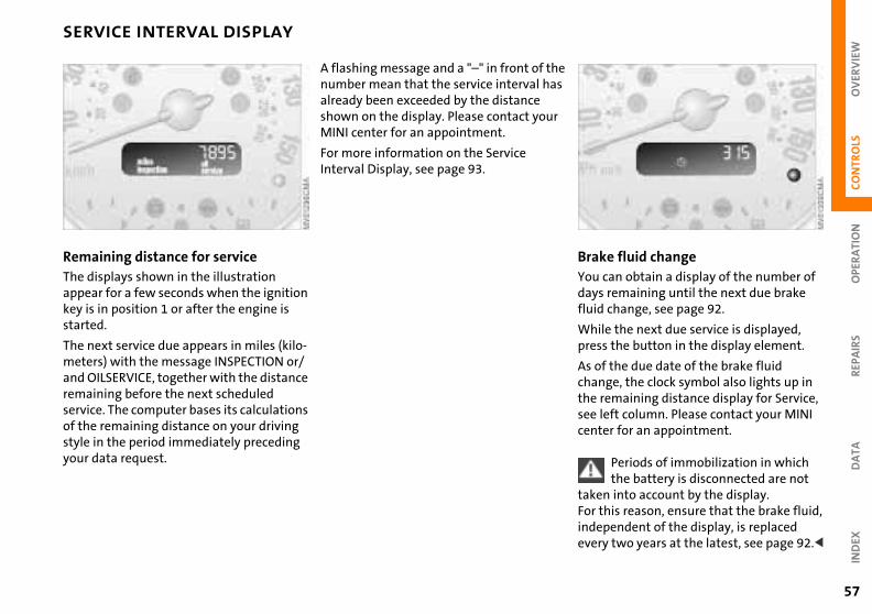
e fluid changecan obtain a display of the number of remaining until the next due brake change, see page 92.
he s
r
BrakYou daysfluid
REP
AIR
SD
ATA
IND
EX
e the next due service is displayed, the button in the display element.
the due date of the brake fluid ge, the clock symbol also lights up in emaining distance display for Service, eft column. Please contact your MINI er for an appointment.
Periods of immobilization in which the battery is disconnected are not
n into account by the display. his reason, ensure that the brake fluid, pendent of the display, is replaced y two years at the latest, see page 92.<
Whilpress
As ofchanthe rsee lcent
takeFor tindeever
57
Remaining distance for serviceThe displays shown in the illustration appear for a few seconds when the ignition key is in position 1 or after the engine is
A flashing message and a "–" in front of tnumber mean that the service interval haalready been exceeded by the distance shown on the display. Please contact youMINI center for an appointment.
For more information on the Service Interval Display, see page 93.
started.
The next service due appears in miles (kilo-meters) with the message INSPECTION or/and OILSERVICE, together with the distance remaining before the next scheduled service. The computer bases its calculations of the remaining distance on your driving style in the period immediately preceding your data request.

58
CLOCK COMPUTER*
isplays appear in the following order:de temperature, cruising range, ge fuel consumption, average vehicle .
ng with ignition key position 1, the ctive setting is displayed.
If the vehicle is equipped with a navi-gation system, see chapter covering mputer in the navigation system r's Manual.<
The dOutsiaveraspeed
Startilast a
the coOwne
y, .
SettingsFrom ignition key position 1:
Left button: hours
Mode selectionWith the ignition key in position 1 and higher, you can use the button in the turnsignal indicator lever to retrieve informa-
Right button: minutesMove forward in increments:Press the button
or
Fast forward:Press and hold the button
Changeover from 24-hour to 12-hour mode:
Press both buttons at the same time for approx. 5 seconds.
tion from the computer for display in the tachometer. By pressing the button brieflyou can call up a new function for display

OV
ERV
IEW
OPE
RA
TIO
NC
ON
TRO
LS
COMPUTER*
or
REP
AIR
SD
ATA
IND
EX
59
Outside temperature If the vehicle is equipped with a tacho-meter, but not with a computer, the temperature is always displayed.
Average speed –Average fuel consumption Press the button in the turn signal indicatlever for a longer period.
The average speed value/consumption value on display is recalculated.
Any time spent when the vehicle is stationary and the engine is switched offis ignored for the calculation.
You can display the exterior tempera-ture and distance driven in other
units of measurement.<
Cruising range The computer bases its calculations for the cruising range on the driving style and on the remaining fuel in the tank.
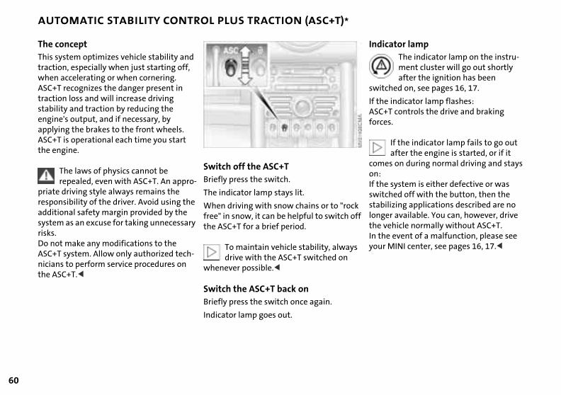
60
AUTOMATIC STABILITY CONTROL PLUS TRACTION (ASC+T)*
ator lampThe indicator lamp on the instru-ment cluster will go out shortly after the ignition has been
hed on, see pages 16, 17.
indicator lamp flashes:T controls the drive and braking s.
If the indicator lamp fails to go out after the engine is started, or if it s on during normal driving and stays
system is either defective or was hed off with the button, then the izing applications described are no r available. You can, however, drive hicle normally without ASC+T. event of a malfunction, please see
MINI center, see pages 16, 17.<
k ff
Indic
switc
If theASC+force
comeon:If theswitcstabillongethe veIn theyour
The conceptThis system optimizes vehicle stability and traction, especially when just starting off, when accelerating or when cornering.ASC+T recognizes the danger present in traction loss and will increase driving stability and traction by reducing the engine's output, and if necessary, by applying the brakes to the front wheels. ASC+T is operational each time you start the engine.
The laws of physics cannot be repealed, even with ASC+T. An appro-
priate driving style always remains the responsibility of the driver. Avoid using the
Switch off the ASC+TBriefly press the switch.
The indicator lamp stays lit.
additional safety margin provided by the system as an excuse for taking unnecessary risks.Do not make any modifications to the ASC+T system. Allow only authorized tech-nicians to perform service procedures on the ASC+T.<
When driving with snow chains or to "rocfree" in snow, it can be helpful to switch othe ASC+T for a brief period.
To maintain vehicle stability, alwaysdrive with the ASC+T switched on
whenever possible.<
Switch the ASC+T back onBriefly press the switch once again.
Indicator lamp goes out.
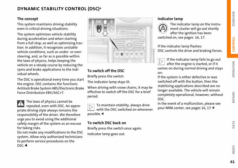
OV
ERV
IEW
REP
AIR
SO
PER
ATI
ON
CO
NTR
OLS
DA
TAD
EX
DYNAMIC STABILITY CONTROL (DSC)*
cator lampThe indicator lamp on the instru-ment cluster will go out shortly after the ignition has been
ched on, see pages 16, 17.
indicator lamp flashes:controls the drive and braking forces.
If the indicator lamp fails to go out after the engine is started, or if it
es on during normal driving and stays
system is either defective or was ched off with the button, then the ilizing applications described are no er available. The vehicle will remain pletely operational, however, without
e event of a malfunction, please see MINI center, see pages 16, 17.<
e
r
Indi
swit
If theDSC
comon:If theswitstablongcomDSC.In thyour
IN
61
The conceptThis system maintains driving stability even in critical driving situations.
The system optimizes vehicle stability during acceleration and when starting from a full stop, as well as optimizing trac-tion. In addition, it recognizes unstable vehicle conditions, such as under- or over-steering, and, as far as is possible within the laws of physics, helps keeping the vehicle on a steady course by reducing the rpms and brake applications to the indi-vidual wheels.
The DSC is operational every time you start the engine. DSC contains the functions
To switch off the DSCBriefly press the switch.
The indicator lamp stays lit.
Antilock Brake System ABS/Electronic Brake Force Distribution EBV/ASC+T.
The laws of physics cannot be repealed, even with DSC. An appro-
priate driving style always remains the responsibility of the driver. We therefore urge you to avoid using the additional safety margin of the system as an excuse for taking risks.Do not make any modifications to the DSC system. Allow only authorized technicians to perform service procedures on the DSC.<
When driving with snow chains, it may beffective to switch off the DSC for a briefperiod.
To maintain stability, always drive with the DSC switched on wheneve
possible.<
To switch DSC back onBriefly press the switch once again.
Indicator lamp goes out.
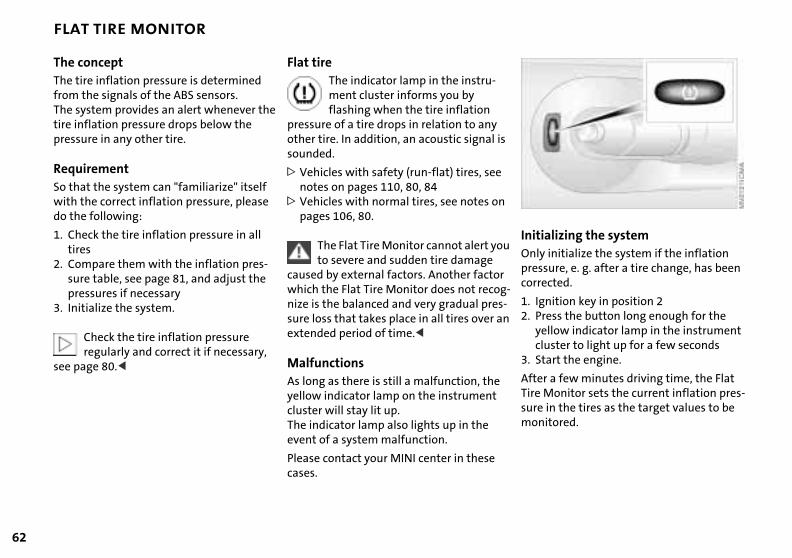
62
FLAT TIRE MONITOR
lizing the systeminitialize the system if the inflation ure, e. g. after a tire change, has been cted.
s
u
InitiaOnly presscorre
ition key in position 2 ss the button long enough for the
llow indicator lamp in the instrument ster to light up for a few secondsrt the engine.
a few minutes driving time, the Flat onitor sets the current inflation pres-
n the tires as the target values to be tored.
--n
1. Ign2. Pre
yeclu
3. Sta
AfterTire Msure imoni
The conceptThe tire inflation pressure is determined from the signals of the ABS sensors.The system provides an alert whenever the tire inflation pressure drops below the pressure in any other tire.
RequirementSo that the system can "familiarize" itself with the correct inflation pressure, please do the following:
1. Check the tire inflation pressure in all tires
2. Compare them with the inflation pres-sure table, see page 81, and adjust the
Flat tireThe indicator lamp in the instru-ment cluster informs you by flashing when the tire inflation
pressure of a tire drops in relation to any other tire. In addition, an acoustic signal isounded.
> Vehicles with safety (run-flat) tires, seenotes on pages 110, 80, 84
> Vehicles with normal tires, see notes onpages 106, 80.
The Flat Tire Monitor cannot alert yoto severe and sudden tire damage
caused by external factors. Another factor
pressures if necessary3. Initialize the system.
Check the tire inflation pressure regularly and correct it if necessary,
see page 80.<
which the Flat Tire Monitor does not recognize is the balanced and very gradual pressure loss that takes place in all tires over aextended period of time.<
MalfunctionsAs long as there is still a malfunction, the yellow indicator lamp on the instrument cluster will stay lit up.The indicator lamp also lights up in the event of a system malfunction.
Please contact your MINI center in these cases.

OV
ERV
IEW
OPE
RA
TIO
NC
ON
TRO
LS
FLAT TIRE MONITOR PARK DISTANCE CONTROL (PDC)*
m malfunctions will be indicated by tinuous high-pitched tone when the m is activated the first time. Please your MINI center resolve the problem.
Even with PDC, final responsibility for estimating the distance between the
le and any obstructions always ins with the driver. Even when sensors
nvolved, there is a blind spot in which cts cannot be detected. Moreover, the ction of obstructions can approach the ical limits of ultrasonic measurement, curs e. g. in the case of thin and
ge-shaped objects. in sources of sound, such as a loud
ct.
o
lly
Systea consystehave
vehicremaare iobjedetephysas ocwedCerta
63
REP
AIR
SD
ATA
IND
EX
, could drown out the PDC signal .<
Keep the sensors clean and free of ice or snow in order to ensure that they
ontinue to operate effectively.ot apply high pressure spray to the ors for a prolonged period of time. ys maintain a distance of more than 10 cm).<
-
he
he e
radiotone
will cDo nsensAlwa4 in (
Do not initialize the system when snow chains are fitted. When driving
with snow chains, false alarms can occur or pressure losses might not be detected.<
In the following situations false alarms can also occur under certain
circumstances or the detection of inflation pressure loss can be delayed:
>When driving on roads covered with snow or on other slippery road surfaces
> A sporty driving style (slip at the driven wheels, high lateral accelerations).<
The conceptThe PDC assists you when you back into aparking space. A signal warns you of the distance to an obstacle. To do this, four ultrasonic sensors in the rear bumper measure the distance to the nearest objeThe range for the sensors located at bothrear corners ends approx. 2 ft (60 cm) behind the bumpers. The range for the twmiddle sensors is slightly less than 5 ft (1.5 meters).
The system starts to operate automaticaabout one second after you select reversewith the ignition key in position 2. PDC isdeactivated when you shift back out of reverse.
Acoustical signalsThe distance to the nearest object is indi-cated by a tone sounding at various intervals. As the distance between vehicle andobject decreases, the intervals between ttones become shorter. A continuous toneindicates the presence of an object less than 9 in (20 cm) away.
The warning signal is canceled after approx. three seconds if the distance to tobstacle remains constant during this tim(if you are moving parallel to a wall, for instance).
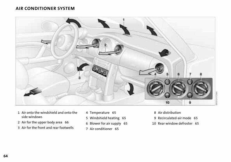
64
AIR CONDITIONER SYSTEM
d and onto the
area 66
ar footwells
4 Temperature 65
5 Windshield heating 65
6 Blower for air supply 65
7 Air conditioner 65
ir distribution
ecirculated-air mode 65
ear window defroster 65
8 A
9 R
10 R
1 Air onto the windshielside windows
2 Air for the upper body
3 Air for the front and re

OV
ERV
IEW
REP
AIR
SO
PER
ATI
ON
CO
NTR
OLS
AIR CONDITIONER SYSTEM
onditionerAir conditioner operation switched on:Indicator lamp lights up.
ir is cooled and dehumidified and – nding on the temperature setting – rmed. the engine start, the windshield can ver briefly.
Condensation forms in the air condi-tioner system during operation, and
exits under the vehicle. Traces of ensed water under the vehicle are fore normal.<
rculated-air modeSupply of outside air into the vehicle is blocked: indicator lamp lights up.
ir within the vehicle is recirculated.
d
d f
n:
d f
Air c
The adeperewaAfterfog o
thencondthere
Reci
The a
DA
TAIN
DEX
Do not run the recirculated-air mode for longer than approx. 30 minutes,
herwise the air quality in the interior eteriorate.<<<<
If the windows fog over in the recir-culated-air mode, switch the recircu-
-air mode off and increase the air ly as required.<<<<
as otwill d
latedsupp
65
Air supplyYou can select blower speeds from 1 to 4. Position 0: blower is switched off. The button for recirculated-air mode fully blocks
the supply of air from outside.
Heating and ventilation operate as of posi-tion 1.
TemperatureTurn to the right (red) to increase the temperature of the passenger compartment.
Rapid heating: turn to the extreme right. Then select a pleasant inte-
Rear window defroster Rear window defroster switcheon: Indicator lamp lights up.
As long as the indicator lamp is lit, the heating operates at high power output (rapid defrosting).
Indicator lamp goes out.The heating continues to run with reducepower output and then switches itself ofautomatically.
Windshield heating*Windshield heating switched oIndicator lamp lights up.
rior temperature.
Air distribution Air distribution in upper body region , upper body region and footwell , footwell , footwell and windows and
windows .All intermediate positions are possible, see illustration and overview on page 64.
As long as the indicator lamp islit, the heating operates at high power output (rapid defrosting).
Indicator lamp goes out.The heating continues to run with reducepower output and then switches itself ofautomatically.
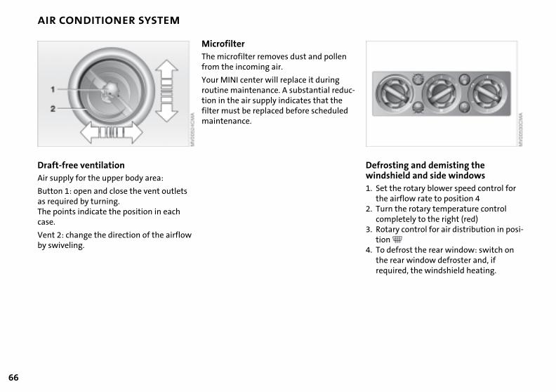
66
AIR CONDITIONER SYSTEM
sting and demisting the shield and side windows
t the rotary blower speed control for airflow rate to position 4
rn the rotary temperature control mpletely to the right (red)tary control for air distribution in posi-n defrost the rear window: switch on rear window defroster and, if uired, the windshield heating.
-
Defrowind1. Se
the2. Tu
co3. Ro
tio4. To
thereq
Draft-free ventilation Air supply for the upper body area:
Button 1: open and close the vent outlets
Microfilter The microfilter removes dust and pollen from the incoming air.
Your MINI center will replace it during routine maintenance. A substantial reduction in the air supply indicates that the filter must be replaced before scheduled maintenance.
as required by turning. The points indicate the position in each case.
Vent 2: change the direction of the airflow by swiveling.
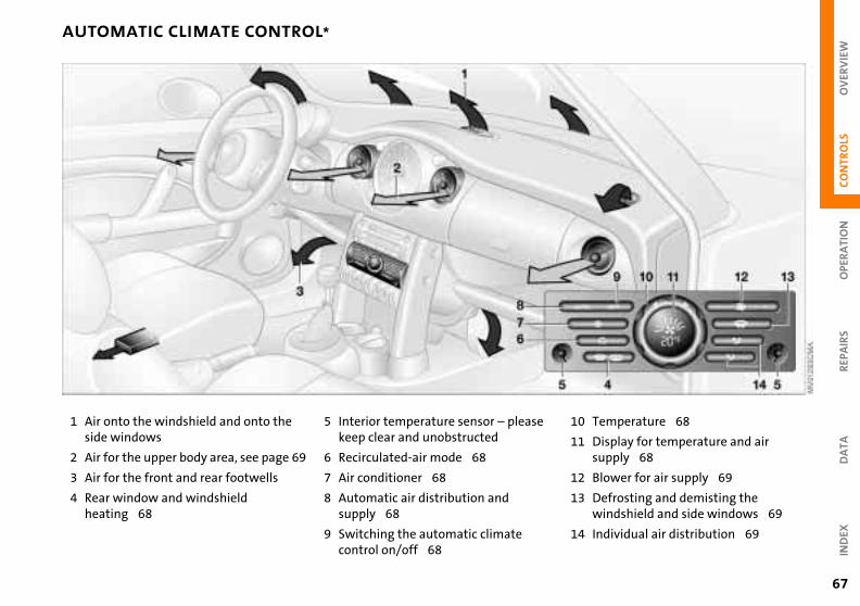
OV
ERV
IEW
PAIR
SO
PER
ATI
ON
CO
NTR
OLS
AUTOMATIC CLIMATE CONTROL*
ld and onto the
area, see page 69
ear footwells
dshield
5 Interior temperature sensor – pleasekeep clear and unobstructed
6 Recirculated-air mode 68
7 Air conditioner 68
8 Automatic air distribution and supply 68
9 Switching the automatic climate control on/off 68
RE
DA
TAIN
DEX
emperature 68
isplay for temperature and air upply 68
lower for air supply 69
efrosting and demisting the indshield and side windows 69
ndividual air distribution 69
10 T
11 Ds
12 B
13 Dw
14 I
67
1 Air onto the windshieside windows
2 Air for the upper body
3 Air for the front and r
4 Rear window and winheating 68
68
AUTOMATIC CLIMATE CONTROL*
window defroster and windshield ing*
Rear window defroster and wind-shield heating switched on:
tor lamp lights up.g as the indicator lamp is lit, the
ng operates at high power output defrosting).
tor lamp goes out.eating continues to run with reduced r output and then switches itself off
atically.
erature Setting the temperature:Move or turn the wheel in the appropriate direction to increase
i-
-
Rearheat
IndicaAs lonheati(rapid
IndicaThe hpoweautom
Temp
the temperature step by step.
igures in the display provide a general tion of interior temperature. When
tart the vehicle, the system ensures he selected temperature is achieved ickly as possible and then maintained.
Permanent heating with maximum power output at temperature selec-HI". Permanent cooling at "LO".<
e
-
The findicayou sthat tas qu
tion "
Automatic air distribution and supplyAutomatic program (AUTO): Indicator lamp lights up.
Automatic adjustment of the air distribu-tion and the air supply and adaptation of the specified temperatures to external influences (outside temperature and sunlight).
In the automatic program (AUTO), the air conditioner is activated automatically.
Switching the automatic climate control on/off
The blower, heating and air condi-tioner are switched off.
After the engine start, the windshield canfog over briefly. Switching on the air condtioner reduces condensation on the windows.
Condensation forms in the air conditioner system during operation, and
then exits under the vehicle. Traces of condensed water under the vehicle are therefore normal.<
Recirculated-air mode Supply of outside air into the vehicle is blocked:
Indicator lamp lights up.The air within the vehicle is recirculated.
To switch the automatic climate control on again:Press any button of the automatic climate control.
Air conditionerAir conditioner switched on:Indicator lamp lights up.
The air is cooled and dehumidified and – depending on the temperature setting – rewarmed.
In the automatic program (AUTO), the air conditioner is activated automatically.
In the automatic program (AUTO) in hot weather conditions, the recirculated-air mode is activated temporarily to enable faster cooling.
Do not run the recirculated-air modfor longer than approx. 30 minutes,
as otherwise the air quality in the interiorwill deteriorate.<
If the windows fog over in the recir-culated-air mode, switch the recircu
lated-air mode off and increase the air supply as required.<
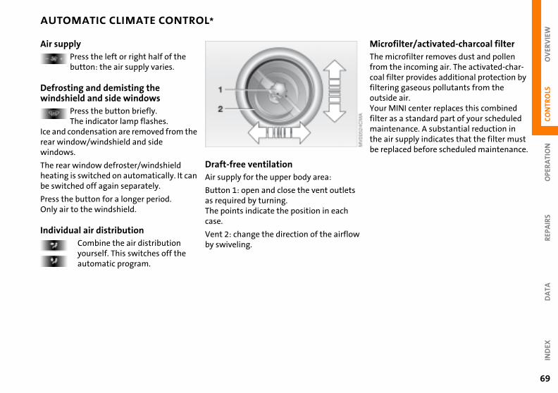
OV
ERV
IEW
REP
AIR
SO
PER
ATI
ON
CO
NTR
OLS
AUTOMATIC CLIMATE CONTROL*
ofilter/activated-charcoal filtericrofilter removes dust and pollen
the incoming air. The activated-char-filter provides additional protection by ing gaseous pollutants from the ide air. MINI center replaces this combined as a standard part of your scheduled tenance. A substantial reduction in ir supply indicates that the filter must placed before scheduled maintenance.
w
MicrThe mfromcoal filteroutsYourfiltermainthe abe re
DA
TAIN
DEX
69
Air supply
Press the left or right half of the button: the air supply varies.
Defrosting and demisting the windshield and side windows
Press the button briefly.The indicator lamp flashes.
Ice and condensation are removed from the rear window/windshield and side windows.
The rear window defroster/windshield heating is switched on automatically. It can be switched off again separately.
Press the button for a longer period.
Draft-free ventilation Air supply for the upper body area:
Button 1: open and close the vent outletsas required by turning.
Only air to the windshield.
Individual air distributionCombine the air distribution yourself. This switches off the automatic program.
The points indicate the position in each case.
Vent 2: change the direction of the airfloby swiveling.
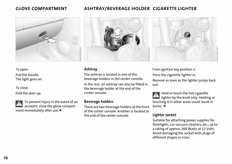
70
GLOVE COMPARTMENT ASHTRAY/BEVERAGE HOLDER CIGARETTE LIGHTER
ignition key position 1:
the cigarette lighter in.
ve as soon as the lighter jumps back
From
Press
Remo
Hold or touch the hot cigarette lighter by the knob only. Holding or ing it in other areas could result in . <
er socketble for attaching power supplies for ights, car vacuum cleaners, etc., up to ng of approx. 200 Watts at 12 Volts. damaging the socket with plugs of ent shapes or sizes.
t t
out.
touchburns
LightSuitaflashla ratiAvoiddiffer
To open:
Pull the handle. The light goes on.
AshtrayThe ashtray is located in one of the beverage holders in the center console.
To close:
Fold the door up.
To prevent injury in the event of an accident, close the glove compart-
ment immediately after use.<
In the rear, an ashtray can also be fitted inthe beverage holder at the end of the center console.
Beverage holdersThere are two beverage holders at the fronof the center console. Another is located athe end of the center console.
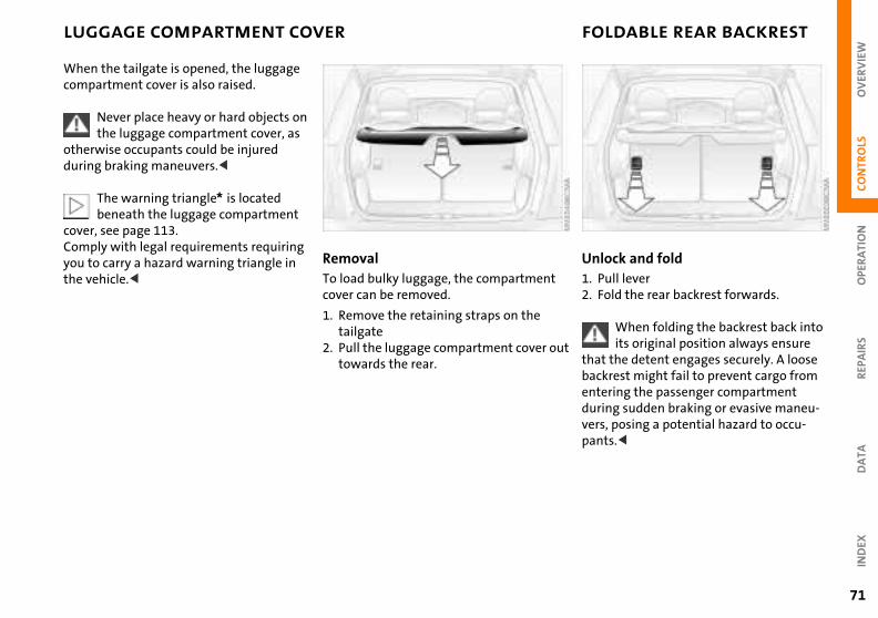
OV
ERV
IEW
PAIR
SO
PER
ATI
ON
CO
NTR
OLS
LUGGAGE COMPARTMENT COVER FOLDABLE REAR BACKREST
ck and foldll leverld the rear backrest forwards.
When folding the backrest back into its original position always ensure
the detent engages securely. A loose
ut
Unlo1. Pu2. Fo
that
RE
DA
TAIN
DEX
rest might fail to prevent cargo from ring the passenger compartment g sudden braking or evasive maneu-
posing a potential hazard to occu-s.<
backentedurinvers,pant
71
When the tailgate is opened, the luggage compartment cover is also raised.
Never place heavy or hard objects on the luggage compartment cover, as
otherwise occupants could be injured during braking maneuvers.<
The warning triangle* is located beneath the luggage compartment
cover, see page 113.Comply with legal requirements requiring you to carry a hazard warning triangle in the vehicle.<
RemovalTo load bulky luggage, the compartmentcover can be removed.
1. Remove the retaining straps on the
tailgate2. Pull the luggage compartment cover otowards the rear.
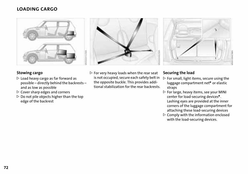
72
LOADING CARGO
ring the load small, light items, secure using the gage compartment net* or elastic
aps large, heavy items, see your MINI ter for load-securing devices*. hing eyes are provided at the inner
n
s.
Secu> For
lugstr
> ForcenLas
corners of the luggage compartment for attaching these load-securing devices> Comply with the information enclosed with the load-securing devices.
Stowing cargo > Load heavy cargo as far forward as
possible – directly behind the backrests – and as low as possible
> For very heavy loads when the rear seatis not occupied, secure each safety belt ithe opposite buckle. This provides addi-tional stabilization for the rear backrest
> Cover sharp edges and corners>Do not pile objects higher than the top
edge of the backrest
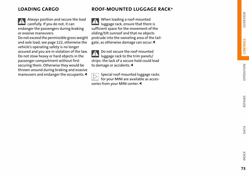
OV
ERV
IEW
OPE
RA
TIO
NC
ON
TRO
LS
LOADING CARGO ROOF-MOUNTED LUGGAGE RACK*
il-
s -
73
REP
AIR
SD
ATA
IND
EX
Always position and secure the load carefully. If you do not, it can
endanger the passengers during braking or evasive maneuvers.Do not exceed the permissible gross weight and axle load, see page 122, otherwise the vehicle's operating safety is no longer assured and you are in violation of the law.Do not stow heavy or hard objects in the passenger compartment without first securing them. Otherwise they would be thrown around during braking and evasive maneuvers and endanger the occupants.<
When loading a roof-mounted luggage rack, ensure that there is
sufficient space for the movement of thesliding/tilt sunroof and that no objects protrude into the swiveling area of the tagate, as otherwise damage can occur.<
Do not secure the roof-mounted luggage rack to the trim panels/
strips: the lack of a secure hold could leadto damage or accidents.<
Special roof-mounted luggage rackfor your MINI are available as acces
sories from your MINI center.<
74
OVERVIEW
CONTROLS
OPERATION, CARE, MAINTENANCE
OWNER SERVICE PROCEDURES
INDEX
TECHNICAL DATA
75
OV
ERV
IEW
REP
AIR
SO
PER
ATI
ON
CO
NTR
OLS
DA
TAIN
DEX
Operation
76
BREAK-IN PROCEDURES GENERAL DRIVING NOTES
ng the vehicleensation forms in the air conditioner m during operation, and then exits r the vehicle. Traces of condensed r under the vehicle are therefore al.
esDo not rest your foot on the brake pedal while driving. Even light but
stent pedal pressure can lead to high eratures, brake wear and possibly brake failure.<
oplaning
t
n
ParkiCondsysteundewatenorm
Brak
consitempeven
Hydr
When driving on wet or slushy roads, reduce road speed. If you do not, a e of water can form between tires and surface. This phenomenon is charac-d by a partial or complete loss of ct between the tires and the roadce. The ultimate results are loss of ing and braking control.<
n
wedgroad terizecontasurfasteer
To ensure that your vehicle provides maximum economy throughout a long service life, we request that you comply with the following information:
EngineUp to 1,200 miles (2,000 km):Attempt to constantly vary both vehicle and engine speed during these initial miles while remembering to avoid engine speeds in excess of 4,500 rpm and/or vehicle speeds of over 95 mph (150 km/h).
Absolutely avoid using the full-throttle or kickdown position for the accelerator.
Once you have driven 1,200 miles
TiresDue to technical factors associated with their manufacture, tires do not achieve their full traction potential until after an initial break-in period. We therefore ask you to drive with extra care during the firs200 miles (300 km).
Brake systemApprox. 300 miles (500 km) must be drivebefore the brake pads and rotors achieve the optimum pad-surface and wear patterns required for trouble-free opera-tion and an extended service life.
(2,000 km), both the engine and vehicle speed can be gradually increased.
You should also comply with these break-in procedures if the engine has to be replaced at a later point.
ClutchRoughly 300 miles (500 km) must be drivebefore the clutch starts to operate at optimum efficiency. Remember to engagethe clutch carefully during this initial period.
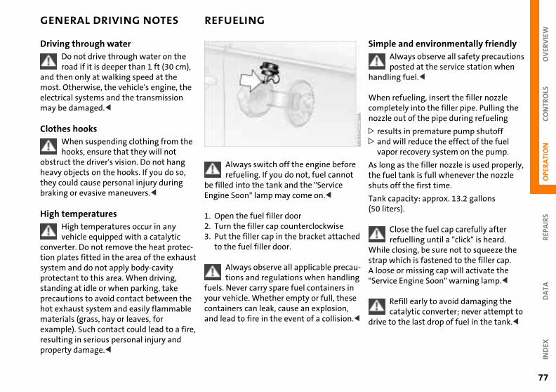
OV
ERV
IEW
OPE
RA
TIO
NC
ON
TRO
LS
GENERAL DRIVING NOTES REFUELING
le and environmentally friendlyAlways observe all safety precautions posted at the service station when
ling fuel.<
n refueling, insert the filler nozzle pletely into the filler pipe. Pulling the le out of the pipe during refueling
sults in premature pump shutoffd will reduce the effect of the fuel por recovery system on the pump.
ng as the filler nozzle is used properly, uel tank is full whenever the nozzle s off the first time.
capacity: approx. 13.2 gallons
e
Simp
hand
Whecomnozz
> re> an
va
As lothe fshut
Tank
REP
AIR
SD
ATA
IND
EX
iters).
Close the fuel cap carefully after refuelling until a "click" is heard.
e closing, be sure not to squeeze the which is fastened to the filler cap. se or missing cap will activate the ice Engine Soon" warning lamp.<
Refill early to avoid damaging the catalytic converter; never attempt to
to the last drop of fuel in the tank.<
d
u-g e
.<
(50 l
WhilstrapA loo"Serv
drive
77
Driving through waterDo not drive through water on the road if it is deeper than 1 ft (30 cm),
and then only at walking speed at the most. Otherwise, the vehicle's engine, the electrical systems and the transmission may be damaged.<
Clothes hooksWhen suspending clothing from the hooks, ensure that they will not
obstruct the driver's vision. Do not hang heavy objects on the hooks. If you do so, they could cause personal injury during braking or evasive maneuvers.<
Always switch off the engine beforrefueling. If you do not, fuel cannot
be filled into the tank and the "Service Engine Soon" lamp may come on.<
High temperaturesHigh temperatures occur in any vehicle equipped with a catalytic
converter. Do not remove the heat protec-tion plates fitted in the area of the exhaust system and do not apply body-cavity protectant to this area. When driving, standing at idle or when parking, take precautions to avoid contact between the hot exhaust system and easily flammable materials (grass, hay or leaves, for example). Such contact could lead to a fire, resulting in serious personal injury and property damage.<
1. Open the fuel filler door 2. Turn the filler cap counterclockwise3. Put the filler cap in the bracket attache
to the fuel filler door.
Always observe all applicable precations and regulations when handlin
fuels. Never carry spare fuel containers inyour vehicle. Whether empty or full, thescontainers can leak, cause an explosion, and lead to fire in the event of a collision
78
FUEL SPECIFICATIONS ANTILOCK BRAKE SYSTEM (ABS)
d
n i-
it
The engine uses lead-free gasoline only.
Required fuel:
> Premium Unleaded Gasoline,
min. 91 AKI. AKI = Anti Knock Index.
Do not use leaded fuels. The use of leaded fuels will cause permanent
damage to the emissions-control system's oxygen sensor and the catalytic converter.<
The concept The ABS keeps the wheels from locking while braking, thereby enhancing active driving safety.
ABS also includes Electronic Brake Force Distribution (EBV).
Braking with ABSTo achieve optimal performance from ABSwhen reacting to critical situations you should apply maximum pressure to the brake pedal ("panic stop").
Since the vehicle maintains steering responsiveness, you can nevertheless avoipossible obstacles with a minimum of
steering effort.Pulsation of the brake pedal in conjunctiowith the sound of hydraulic regulation indcates to you that you are driving at the limand reminds you to readapt your vehicle'sspeed to road surface conditions.
OV
ERV
IEW
OPE
RA
TIO
NC
ON
TRO
LS
BRAKE SYSTEM
e padsFor your own safety: use only brake pads that the manufacturer has
sed for your particular vehicle model. anufacturer cannot evaluate non-
oved brake pads to determine if they uited for use, and therefore cannot re the operating safety of the vehicle y are installed.<
rs
ri-
e
Brak
releaThe mapprare sensuif the
REP
AIR
SD
ATA
IND
EX
d r
is r <
79
Brake fluid level If the brake fluid level is too low and brake pedal travel has become longer, there may be a defect in one of the brake system's hydraulic circuits.
Proceed to the nearest MINI center. Higher brake application pressure
may be necessary under these conditions, there may be slight "pull" to one side, and brake pedal travel may be longer. Please remember to adapt your driving style accordingly.<
Disc brakesWhen the vehicle is driven only occasion-
It is a good idea to periodically dry the brakes with a gentle application when driving in rain and on wet roads.Monitor traffic conditions to ensure thatthis maneuver does not endanger other road users. The heat generated in this process helps dry the brake pads and rototo ensure that your brake system will respond with undiminished efficiency when you need it.
Extended or steep mountain descents should be driven in the gear or in the driving position in which only minimal peodic brake application is required. This helps avoid placing excessive loads on thbrake system. Stay within the allowable
ally, during extended periods when the vehicle is not used at all, and in operating conditions where brake applications are less frequent, there is an increased tendency for corrosion of the brake rotors and accumulation of contamination on the brake pads. This occurs because the minimal pressure that must be exerted by the pads to clean the rotors by brake appli-cations is not reached.
Corrosion on brake rotors is signaled by a running or pulsation during braking; even extended subsequent braking will not cure this phenomenon.
speed range, refer to page 55.
Do not coast with the clutch presseor with the transmission or selecto
lever in Neutral. Do not coast with the engine switched off. The engine providesno braking effect when the transmisson in neutral and there is no power-assist fobraking when the engine is switched off.
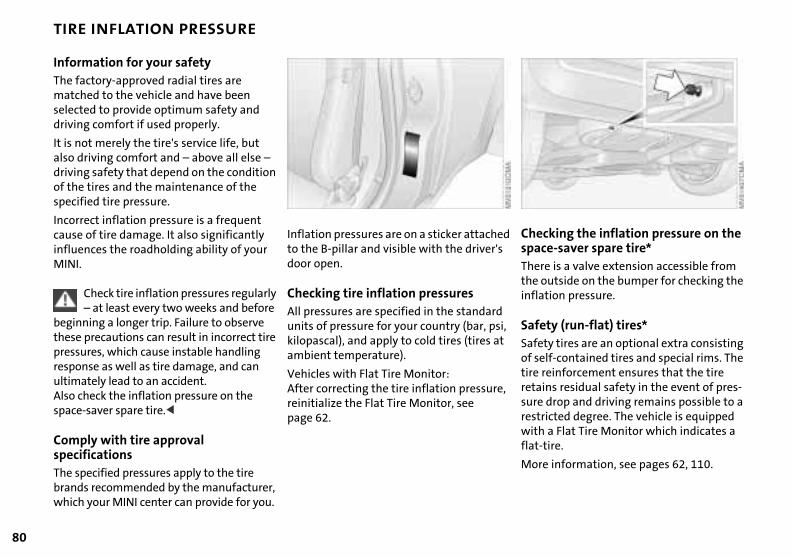
80
TIRE INFLATION PRESSURE
king the inflation pressure on the -saver spare tire*
is a valve extension accessible from utside on the bumper for checking the
d
ChecspaceTherethe o
ion pressure.
y (run-flat) tires* y tires are an optional extra consisting f-contained tires and special rims. The inforcement ensures that the tire s residual safety in the event of pres-rop and driving remains possible to a
cted degree. The vehicle is equipped a Flat Tire Monitor which indicates a ire.
information, see pages 62, 110.
i,
,
inflat
SafetSafetof seltire reretainsure drestriwith flat-t
More
Information for your safetyThe factory-approved radial tires are matched to the vehicle and have been selected to provide optimum safety and driving comfort if used properly.
It is not merely the tire's service life, but also driving comfort and – above all else – driving safety that depend on the condition of the tires and the maintenance of the specified tire pressure.
Incorrect inflation pressure is a frequent cause of tire damage. It also significantly influences the roadholding ability of your MINI.
Inflation pressures are on a sticker attacheto the B-pillar and visible with the driver'sdoor open.
Check tire inflation pressures regularly – at least every two weeks and before
beginning a longer trip. Failure to observe these precautions can result in incorrect tire pressures, which cause instable handling response as well as tire damage, and can ultimately lead to an accident. Also check the inflation pressure on the space-saver spare tire.<
Comply with tire approval specificationsThe specified pressures apply to the tire brands recommended by the manufacturer, which your MINI center can provide for you.
Checking tire inflation pressuresAll pressures are specified in the standardunits of pressure for your country (bar, pskilopascal), and apply to cold tires (tires atambient temperature).
Vehicles with Flat Tire Monitor:After correcting the tire inflation pressurereinitialize the Flat Tire Monitor, see page 62.
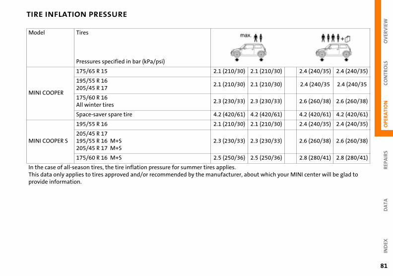
OV
ERV
IEW
OPE
RA
TIO
NC
ON
TRO
LS
TIRE INFLATION PRESSURE
30) 2.4 (240/35) 2.4 (240/35)
30) 2.4 (240/35 2.4 (240/35
33) 2.6 (260/38) 2.6 (260/38)
61) 4.2 (420/61) 4.2 (420/61)
30) 2.4 (240/35) 2.4 (240/35)
33) 2.6 (260/38) 2.6 (260/38)
2.5 (250/36)
sure for summer tires applies.mmended by the manufacturer, ab
2.1 (210/
2.1 (210/
2.3 (230/
4.2 (420/
2.1 (210/
2.3 (230/
REP
AIR
SD
ATA
IND
EX
36) 2.8 (280/41) 2.8 (280/41)
h your MINI center will be glad to
2.5 (250/
out whic
81
Model Tires
Pressures specified in bar (kPa/psi)
MINI COOPER
175/65 R 15 2.1 (210/30)
195/55 R 16205/45 R 17
2.1 (210/30)
175/60 R 16All winter tires
2.3 (230/33)
Space-saver spare tire 4.2 (420/61)
MINI COOPER S
195/55 R 16 2.1 (210/30)
205/45 R 17195/55 R 16 M+S 2.3 (230/33)
205/45 R 17 M+S175/60 R 16 M+S
In the case of all-season tires, the tire inflation presThis data only applies to tires approved and/or recoprovide information.
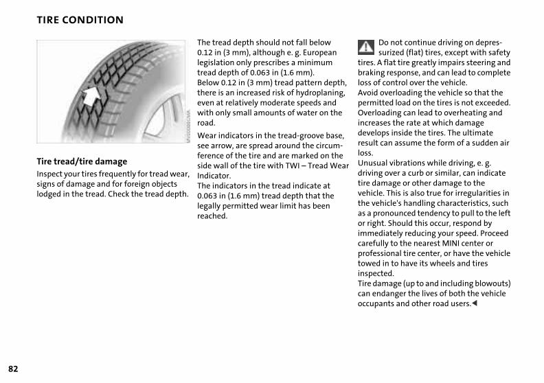
82
TIRE CONDITION
Do not continue driving on depres-surized (flat) tires, except with safety A flat tire greatly impairs steering and ng response, and can lead to complete f control over the vehicle. overloading the vehicle so that the itted load on the tires is not exceeded. oading can lead to overheating and ses the rate at which damage
ops inside the tires. The ultimate can assume the form of a sudden air
ual vibrations while driving, e. g. g over a curb or similar, can indicate
amage or other damage to the le. This is also true for irregularities in hicle's handling characteristics, such
ronounced tendency to pull to the left ht. Should this occur, respond by diately reducing your speed. Proceed
ully to the nearest MINI center or ssional tire center, or have the vehicle d in to have its wheels and tires cted.amage (up to and including blowouts) ndanger the lives of both the vehicle
,
r
tires. brakiloss oAvoidpermOverlincreadevelresultloss.Unusdrivintire dvehicthe veas a por rigimmecarefprofetoweinspeTire dcan e
ants and other road users.<
occupTire tread/tire damageInspect your tires frequently for tread wear, signs of damage and for foreign objects lodged in the tread. Check the tread depth.
The tread depth should not fall below 0.12 in (3 mm), although e. g. European legislation only prescribes a minimum tread depth of 0.063 in (1.6 mm). Below 0.12 in (3 mm) tread pattern depththere is an increased risk of hydroplaning,even at relatively moderate speeds and with only small amounts of water on the road.
Wear indicators in the tread-groove base,see arrow, are spread around the circum-ference of the tire and are marked on the side wall of the tire with TWI – Tread WeaIndicator. The indicators in the tread indicate at 0.063 in (1.6 mm) tread depth that the
legally permitted wear limit has been reached.
OV
ERV
IEW
OPE
RA
TIO
NC
ON
TRO
LS
TIRE REPLACEMENT
ained high temperature can cause the rial of the tire to degenerate and
ce tire life, and excessive temperature ead to a sudden flat tire. The grade C sponds to a level of performance h all passenger car tires must meet r the Federal Motor Car Safety Stan-
No. 109. Grades B and A represent er levels of performance on the labora-test wheel than the minimum required w.
The temperature grade for this tire is established for a tire that is properly
ted and not overloaded. Excessive d, underinflation, or excessive loading,
s
g n
st,
o r -e.
Sustmatereducan lcorrewhicundedardhightory by la
inflaspee
REP
AIR
SD
ATA
IND
EX
r separately or in combination, can e heat buildup and possible tire re.<
orm Tire Quality Grading ity grades can be found where appli- on the tire sidewall between tread lder and maximum section width. For ple:
d wear 200 ion AA
perature A
de
t), e o
or
eithecausfailu
UnifQualcableshouexam
TreaTractTem
83
To maintain good handling and vehicle response, use only tires of a single tread configuration from a single manufacturer. The manufacturer of your MINI tests and approves wheel and tire combinations.
Do not use retreaded tires, since driving safety may be impaired. This
is due to the possible variations in casing structures and, in some cases, to their extreme age, which can lead to a decrease in their durability.<
DOT Quality GradesTread wear
Traction AA A B C
The relative performance of tires dependupon the actual conditions of their use, however, and may depart significantly from the norm due to variations in drivinhabits, service practices and differences iroad characteristics and climate.
TractionThe traction grades, from highest to loweare AA, A, B, and C.
Those grades represent the tire's ability tstop on wet pavement as measured undecontrolled conditions on specified government test surfaces of asphalt and concretA tire marked C may have poor traction performance.
Temperature A B C
All passenger car tires must conform to Federal Safety Requirements in
addition to these grades.<
Tread wearThe tread wear grade is a comparative rating based on the wear rate of the tire when tested under controlled conditions on a specified government test course.
For example, a tire graded 150 would wear one and one-half (1 g) times as well on the government course as a tire graded 100.
The traction grade assigned to this tire is based on straight-ahead
braking traction tests, and does not incluacceleration, cornering, hydroplaning, or peak traction characteristics.<
TemperatureThe temperature grades are A (the highesB, and C, representing the tire's resistancto the generation of heat and its ability tdissipate heat when tested under controlled conditions on a specified indolaboratory test wheel.
84
TIRE REPLACEMENT WHEEL AND TIRE COMBINATIONS
The correct wheel and tire combina-tion affects various systems that
d otherwise be impaired, e.g. ABS, T and DSC.is reason, use only tires of the same facture and tread configuration. In
vent of a flat tire, for example, unt the approved wheel and tire ination as soon as possible.<
ge tires in a cool, dry place, protecting against light whenever possible. ct the tires against contact with oil, e and fuel.
d
c-
woulASC+For thmanuthe eremocomb
StoraStorethemProtegreas
hanges between axlesnding on individual operating condi-, different wear patterns appear on ont and rear axles. In the interests of y and optimized handling characteris- change between the axles is not mended.
Tire cDepetionsthe frsafettics, arecom
Tire age The date on which the tire was manufac-tured is indicated by the code on the side-wall:
DOT ... 1202 indicates that the tire was manufactured in Week 12 of the year 2002.
The manufacturer of your MINI recom-mends replacement of all tires – including the space-saver spare tire, after no more than 6 years.
Safety (run-flat) tires*For replacement, use only safety tires, as in the event of a flat tire there is no
space-saver spare tire.
The right choiceThe factory-approved normal tires and safety tires are matched to the vehicle anhave been selected to provide optimum driving safety and the desired driving comfort.
Never mount wheels and tires that have not been specifically approved
by the manufacturer for use on your partiular model. Although other wheels and tires may theoretically have the same dimensions, variations in factors such as manufacturing tolerances can result in contact between tire and bodywork, ulti-mately leading to serious accidents. The
You will recognize safety tires by a circular symbol containing the letters RSC on the side of the tire, see pages 110, 80.<
manufacturer cannot evaluate non-approved wheels and tires to determine ifthey are suited for use, and therefore cannot ensure the operating safety of thevehicle if they are fitted.<
The manufacturer has tested certain tire brands in each size, categorized them as safe for use on the road, and approved them. Contact your MINI center for more details.
OV
ERV
IEW
REP
AIR
SO
PER
ATI
ON
CO
NTR
OLS
DA
TA
WINTER TIRES SNOW CHAINS*
The use of narrow-link snow chains is permitted in pairs only and only on
ront wheels with the following tires:65 R 15 60 R 16 n fitting, comply with the manufac-'s instructions.<
With chains, do not exceed a speed of 30 mph (50 km/h).<
After fitting the snow chains, do not activate the Flat Tire Monitor.
n driving with snow chains, it can be ful to switch off the ASC+T or DSC for ef period, see pages 60, 61.<
-
es-
d
n p-
the f175/175/Wheturer
Whehelpa bri
IND
EX
85
Choosing the right tireThe manufacturer recommends winter tires (M+S radial tires) for driving in adverse winter road conditions. While so-called all-season tires (M+S designation) provide better winter traction than summer tires with the load ratings S, T, H, V, W, they do not achieve the performance of winter tires.
In the interest of safe tracking and steering response, install winter tires made by the same manufacturer having the same tread configuration on all four wheels.
Before purchasing winter tires, check whether your MINI is fitted with safety
Observing speedsNever exceed the maximum speedfor which the tires are rated.
Unprofessional attempts by laymen to service tires can lead to damage and accidents.Have this work performed by skilled profsionals only. Your MINI center will be gladto assist you with both their expertise anthe proper equipment for your vehicle.<
Tire condition, tire inflation pressureOnce the tire wears to below 0.16 i(4 mm), winter tires display a perce
tible decrease in their ability to cope withwinter driving conditions, and should be
tires. You will recognize safety tires by acircular symbol containing the letters RSC on the side of the tire, see page 110. In this case, use only safety tires, as in the event of a flat tire there is no space-saver spare tire.
Only winter tires recommended by the manufacturer of your MINI should be fitted. Any MINI center will be glad to advise you on the selection of the right winter tires for the relevant operating conditions.
replaced in the interest of safety.<
Comply with the specified tire inflation pressures and be sure to have the wheel and tire assemblies balanced every time you change the tires.
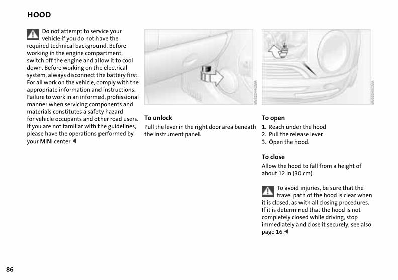
86
HOOD
enach under the hoodll the release leveren the hood.
ose the hood to fall from a height of
t 12 in (30 cm).
To avoid injuries, be sure that the travel path of the hood is clear when
losed, as with all closing procedures. determined that the hood is not letely closed while driving, stop
h
To op1. Re2. Pu3. Op
To clAllowabou
it is cIf it iscomp
diately and close it securely, see also 16.<
immepage
Do not attempt to service your vehicle if you do not have the
required technical background. Before working in the engine compartment, switch off the engine and allow it to cool down. Before working on the electrical system, always disconnect the battery first. For all work on the vehicle, comply with the appropriate information and instructions. Failure to work in an informed, professional manner when servicing components and materials constitutes a safety hazard for vehicle occupants and other road users. If you are not familiar with the guidelines, please have the operations performed by your MINI center.<
To unlock Pull the lever in the right door area beneatthe instrument panel.
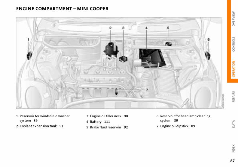
OV
ERV
IEW
REP
AIR
SO
PER
ATI
ON
CO
NTR
OLS
DA
TA
ENGINE COMPARTMENT – MINI COOPER
washer
91
3 Engine oil filler neck 90
4 Battery 111
5 Brake fluid reservoir 92
ervoir for headlamp cleaning tem 89
ine oil dipstick 89
6 Ressys
7 Eng
IND
EX
87
1 Reservoir for windshieldsystem 89
2 Coolant expansion tank
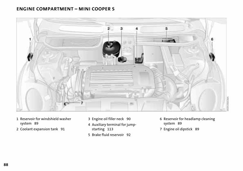
88
ENGINE COMPARTMENT – MINI COOPER S
washer
91
3 Engine oil filler neck 90
4 Auxiliary terminal for jump-starting 113
5 Brake fluid reservoir 92
6 Reservoir for headlamp cleaning system 89
ine oil dipstick 89
7 Eng1 Reservoir for windshieldsystem 89
2 Coolant expansion tank
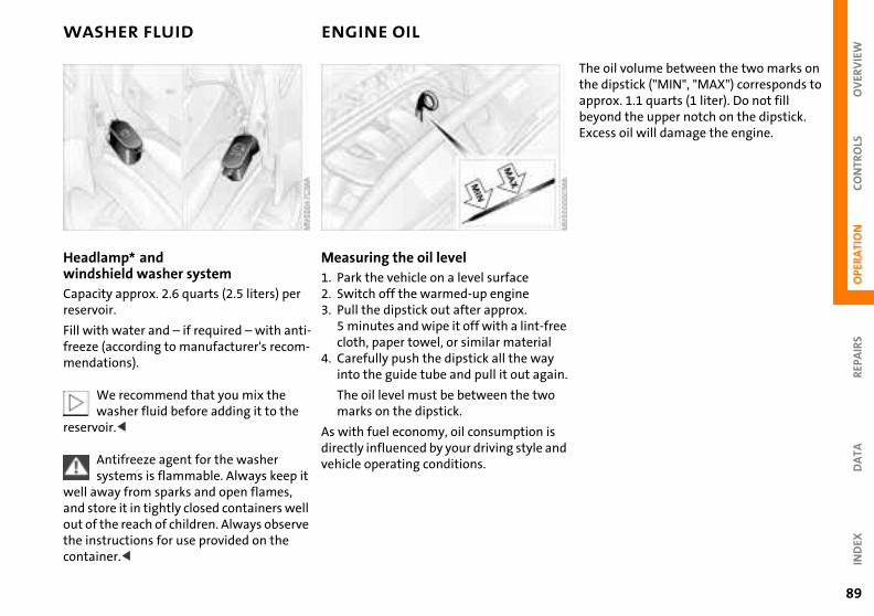
OV
ERV
IEW
OPE
RA
TIO
NC
ON
TRO
LS
WASHER FLUID ENGINE OIL
il volume between the two marks on ipstick ("MIN", "MAX") corresponds to
ox. 1.1 quarts (1 liter). Do not fill nd the upper notch on the dipstick. ss oil will damage the engine.
The othe dapprbeyoExce
REP
AIR
SD
ATA
IND
EX
ee
in.
d
89
Headlamp* and windshield washer systemCapacity approx. 2.6 quarts (2.5 liters) per reservoir.
Measuring the oil level 1. Park the vehicle on a level surface2. Switch off the warmed-up engine3. Pull the dipstick out after approx.
Fill with water and – if required – with anti-freeze (according to manufacturer's recom-mendations).
We recommend that you mix the washer fluid before adding it to the
reservoir.<
Antifreeze agent for the washer systems is flammable. Always keep it
well away from sparks and open flames, and store it in tightly closed containers well out of the reach of children. Always observe the instructions for use provided on the container.<
5 minutes and wipe it off with a lint-frcloth, paper towel, or similar material
4. Carefully push the dipstick all the wayinto the guide tube and pull it out aga
The oil level must be between the twomarks on the dipstick.
As with fuel economy, oil consumption isdirectly influenced by your driving style anvehicle operating conditions.

90
ENGINE OIL
oved engine oilsuality of the engine oil selected has l significance for the operation and e life of an engine. Based on extensive g, the manufacturer approves only
in grades of engine oil.
You can find out from your MINI center which individual oils have approved by the manufacturer.<
native oil specifications are unable to obtain one of these oils, ay use small volumes of other oils
een oil changes in exceptional cases.
f
-
ApprThe qcriticaservictestincerta
been
AlterIf youyou mbetw
f the following oil specifications must the oil package:
ferred: BMW Longlife-01ernative: BMW Longlife-98, W Longlife or ACEA A3.
One obe on
> Pre> Alt
BM
Adding engine oil Only top up oil when the oil level has dropped to just above the lower notch of the dipstick, but before it goes below this
Continuous exposure to used oil hascaused cancer in laboratory testing.
For this reason, any skin areas that come into contact with oil should be thoroughlywashed with soap and water.Always store oil, grease, etc., out of reach ochildren. Comply with all warning labels and information on lubricant containers.<
Comply with the applicable environmental laws regulating the disposal
of used oil.<
mark.
MINI engines are designed to operate without oil additives; the use of addi-
tives could lead to damage in some cases. This also applies to the CVT, the manual transmission, and the differential.<
The manufacturer recommends that you have the oil changed only at your MINI center.
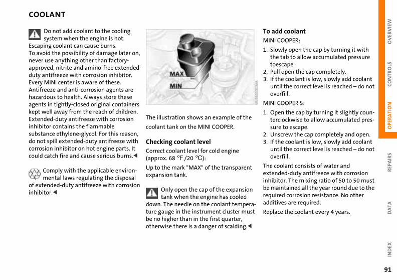
OV
ERV
IEW
OPE
RA
TIO
NC
ON
TRO
LS
COOLANT
dd coolantI COOPER:
owly open the cap by turning it with e tab to allow accumulated pressure escape.ll open the cap completely.
the coolant is low, slowly add coolant til the correct level is reached – do not erfill.
I COOPER S:
pen the cap by turning it slightly coun-rclockwise to allow accumulated pres-re to escape.
nscrew the cap completely and open.the coolant is low, slowly add coolant
To aMIN
1. Slthto
2. Pu3. If
unov
MIN
1. Otesu
2. U3. If
REP
AIR
SD
ATA
IND
EX
til the correct level is reached – do not erfill.
oolant consists of water and nded-duty antifreeze with corrosion itor. The mixing ratio of 50 to 50 must aintained all the year round due to the ired corrosion resistance. No other tives are required.
ace the coolant every 4 years.
a-t
unov
The cexteinhibbe mrequaddi
Repl
91
Do not add coolant to the cooling system when the engine is hot.
Escaping coolant can cause burns.To avoid the possibility of damage later on, never use anything other than factory-approved, nitrite and amino-free extended-duty antifreeze with corrosion inhibitor. Every MINI center is aware of these.Antifreeze and anti-corrosion agents are hazardous to health. Always store these agents in tightly-closed original containers kept well away from the reach of children.Extended-duty antifreeze with corrosion inhibitor contains the flammable substance ethylene-glycol. For this reason, do not spill extended-duty antifreeze with
The illustration shows an example of the
coolant tank on the MINI COOPER.
Checking coolant level
corrosion inhibitor on hot engine parts. It could catch fire and cause serious burns.<Comply with the applicable environ-mental laws regulating the disposal
of extended-duty antifreeze with corrosion inhibitor.<
Correct coolant level for cold engine (approx. 68 7/20 6):
Up to the mark "MAX" of the transparentexpansion tank.
Only open the cap of the expansiontank when the engine has cooled
down. The needle on the coolant temperture gauge in the instrument cluster musbe no higher than in the first quarter, otherwise there is a danger of scalding.<
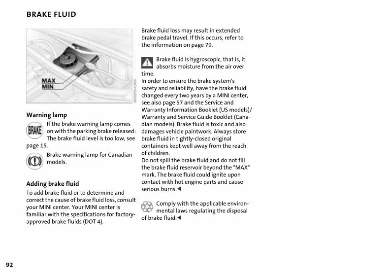
92
BRAKE FLUID
,
)/-
"
-
Warning lampIf the brake warning lamp comes on with the parking brake released: The brake fluid level is too low, see
Brake fluid loss may result in extended brake pedal travel. If this occurs, refer to the information on page 79.
Brake fluid is hygroscopic, that is, it absorbs moisture from the air over
time.In order to ensure the brake system's safety and reliability, have the brake fluid changed every two years by a MINI centersee also page 57 and the Service and Warranty Information Booklet (US modelsWarranty and Service Guide Booklet (Canadian models). Brake fluid is toxic and also damages vehicle paintwork. Always store brake fluid in tightly-closed original
page 15.
Brake warning lamp for Canadian models.
Adding brake fluidTo add brake fluid or to determine and correct the cause of brake fluid loss, consult your MINI center. Your MINI center is familiar with the specifications for factory-approved brake fluids (DOT 4).
containers kept well away from the reachof children.Do not spill the brake fluid and do not fill the brake fluid reservoir beyond the "MAXmark. The brake fluid could ignite upon contact with hot engine parts and cause serious burns.<
Comply with the applicable environmental laws regulating the disposal
of brake fluid.<
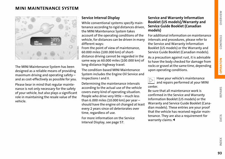
OV
ERV
IEW
REP
AIR
SO
PER
ATI
ON
CO
NTR
OLS
MINI MAINTENANCE SYSTEM
ce and Warranty Information let (US models)/Warranty and ce Guide Booklet (Canadian els) ditional information on maintenance als and procedures, please refer to
ervice and Warranty Information et (US models) or the Warranty and e Guide Booklet (Canadian models).
recaution against rust, it is advisable ve the body checked for damage from or gravel at the same time, depending operating conditions.
Have your vehicle's maintenance and repairs performed at your MINI r.re that all maintenance work is rmed in the Service and Warranty
-,
y
f
d
ServiBookServimodFor adintervthe SBooklServic
As a pto harocksupon
centeBe suconfi
DA
TAIN
DEX
ation Booklet (US models) or the anty and Service Guide Booklet (Cana-
odels). These entries are your proof he vehicle has received regular main-ce. They are also a requirement for nty claims.<
t
InformWarrdian mthat ttenanwarra
93
The MINI Maintenance System has been designed as a reliable means of providing maximum driving and operating safety – and as cost-effectively as possible for you.
Service Interval DisplayWhile conventional systems specify maintenance according to rigid distances driventhe MINI Maintenance System takes account of the operating conditions of thevehicle, for distances can be driven in mandifferent ways:From the point of view of maintenance, 60.000 miles (100.000 km) of short-distance driving cannot be regarded in thesame way as 60.000 miles (100.000 km) olong-distance highway travel.
The condition-based MINI Maintenance System includes the Engine Oil Service anInspections I and II.
Please bear in mind that regular mainte-nance is not only necessary for the safety of your vehicle, but also plays a significant role in maintaining the resale value of the vehicle.
Determining the maintenance intervals according to the actual use of the vehicle covers every kind of operating situation. People who drive very little – much less than 6.000 miles (10.000 km) per year – should have the engine oil changed at leasevery 2 years since oil deteriorates over time, regardless of use.
For more information on the Service Interval Display, see page 57.

94
CARING FOR YOUR VEHICLE
of upholstery ssions that come about on the uphol-
material of the seats in daily use can ushed out using a slightly damp brush st the grain.
act that velour lays down is not a ty defect, but rather is inevitable in
se of home textiles or clothing mate-
case of strong sunlight and longer ng periods, cover the seats or all ows to prevent discoloration.
of special parts ht-alloy wheels:
d
t ).
i-
CareDeprestery be bragain
The fqualithe carials.
In theparkiwind
Care> Lig
wheel cleaner especially during the ter months, but do not use any ressive, acidic, strong alkali or rough
ansers or steam jets above 140 7 6) (observe the manufacturer's rating instructions)
rome parts* such as cooler grille, door dles, etc.:ecially if exposed to road salt, care-
ly clean these parts with plenty of ter and possibly with a shampoo addi-. For additional treatment, use
ome polish
e
e
Usewinaggcle(60ope
> ChhanEspfulwativechr
Suitable car-care productsUse the cleaning and car-care prod-ucts available at your MINI center.<
Washing your vehicle You can wash your new MINI from the outset in automatic car washes, though you should use brushless car washes.
When using steam jets or high-pres-sure washers, ensure that you keep
the jets sufficiently far away from the vehicle. If the jet is too close or the pressure is too high, this can lead to damage or initial damage that can develop into more
Rod antennaIf necessary, before entering a car wash or garage with elevator ramp
for example, remove the rod antenna. To do so, grip the rod antenna at the base anunscrew it from the antenna foot by turning it to the left.<
HeadlampsWhen cleaning the headlamps, please observe the following: do no
clean by wiping with a dry cloth (scratchesNever use abrasives or strong solvents to clean the covers. Remove dirt and contamnation (such as insects) by soaking with
serious damage. Water that enters vehicle components can lead to damage over the long term.<
After washing the vehicle, apply the brakes briefly to dry them, otherwise
water can reduce braking efficiency over the short term and the brake rotors can corrode. <
Switch the rain sensor off when passing through an automatic car
wash, see page 51. Failure to do so could result in damage caused by undesired wiper activation.<
shampoo and then rinsing with plenty of water. Always use a deicer spray to removaccumulated ice and snow – never use a scraper.<
Vehicle paintwork Regular care contributes greatly to drivingsafety and value retention.
Environmental influences varying from onregion to the next can affect the vehicle paintwork. Please base the frequency andscope of car care on these various influ-ences.
OV
ERV
IEW
OPE
RA
TIO
NC
ON
TRO
LS
CARING FOR YOUR VEHICLE
Cleaning agents can contain hazardous or health-damaging
tances. For this reason, always observe arnings on the package.terior cleaning, always open the doors
indows of the vehicle. Do not use any ucts (e.g. solvents) that are not ded for cleaning the vehicle.<
e
a
ll
as
h he
substhe wFor inor wprodinten
REP
AIR
SD
ATA
IND
EX
d
id
95
> Rubber parts:Treat only with water or rubber care products
> Plastic parts, imitation leather surfaces, headliner, lamp glass, covering glass for the instrument cluster, as well as matt black molded parts:Clean with water and, if necessary, plastic care products. Do not dampen seats and the headliner. Never use solvents such as lacquer thinner, heavy-duty grease remover, fuel or similar
> Safety belts:Only clean using mild soap, leaving the belts fitted; do not dry clean, as the fabric can be destroyed.
Use only wiper blades which havbeen approved by the manufac-
turer.<
Leather care The leather* used by the manufacturer ishigh-quality natural product processed using state-of-the-art methods, and it wiretain its quality level for many years if cared for appropriately.
Regular cleaning and care are necessary, dust and road dirt scratches in pores andcreases and lead to heavy wear as well aspremature brittleness of the leather surface. This is why you should use a clotor vacuum cleaner to remove dust from t
Always unroll automatic safety beltswhen dry. Dirty safety belts prevent unrolling and thus negatively affect safety
> Floor carpets and floor mats*:If heavily soiled, clean using interior cleaner. Floor mats can be removed to allow the interior to be cleaned
>Wiper blades:Clean with soapy water. Replace wiper blades twice a year, before and after the cold season. This is particularly impor-tant on vehicles fitted with a rain sensor.
leather on a regular basis.
As dirt and grease can slowly affect the protective layer of the leather, the cleaneleather surfaces must be treated with leather care agent. This also helps to avoelectrostatic charges.
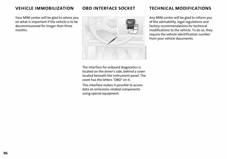
96
VEHICLE IMMOBILIZATION OBD INTERFACE SOCKET TECHNICAL MODIFICATIONS
INI center will be glad to inform you advisability, legal regulations and
ry recommendations for technical fications to the vehicle. To do so, they re the vehicle identification number your vehicle documents.
r e
Any Mof thefactomodirequifrom
Your MINI center will be glad to advise you on what is important if the vehicle is to be decommissioned for longer than three months.
The interface for onboard diagnostics is located on the driver's side, behind a covelocated beneath the instrument panel. Thcover has the letters "OBD" on it.
This interface makes it possible to access data on emissions-related components using special equipment.

OV
ERV
IEW
REP
AIR
SO
PER
ATI
ON
CO
NTR
OLS
DA
TA
CALIFORNIA PROPOSITION 65 WARNING
ND
EX
97
I
California laws require us to state the following warning:
Engine exhaust, some of its constitu-ents, and certain vehicle components
contain or emit chemicals known to the State of California to cause cancer and birth defects or other reproductive harm.<
98
OVERVIEW
CONTROLS
OPERATION, CARE, MAINTENANCE
OWNER SERVICE PROCEDURES
INDEX
TECHNICAL DATA
99
OV
ERV
IEW
REP
AIR
SO
PER
ATI
ON
CO
NTR
OLS
DA
TAIN
DEX
Repairs
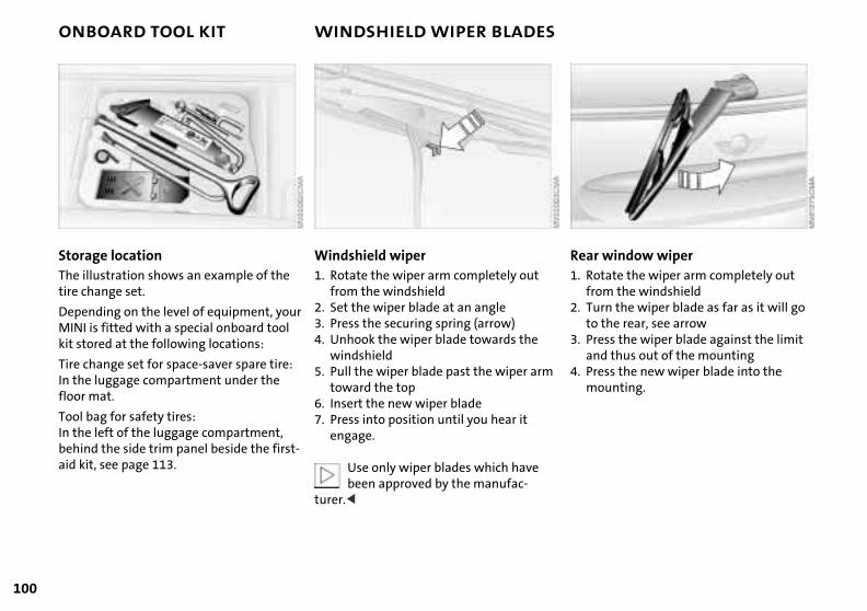
100
ONBOARD TOOL KIT WINDSHIELD WIPER BLADES
window wipertate the wiper arm completely out m the windshieldrn the wiper blade as far as it will go
Rear1. Ro
fro2. Tu
the rear, see arrowss the wiper blade against the limit
d thus out of the mountingss the new wiper blade into the unting.
to 3. Pre
an4. Pre
mo
Storage locationThe illustration shows an example of the tire change set.
Depending on the level of equipment, your
Windshield wiper1. Rotate the wiper arm completely out
from the windshield2. Set the wiper blade at an angle
MINI is fitted with a special onboard tool kit stored at the following locations:
Tire change set for space-saver spare tire:In the luggage compartment under the floor mat.
Tool bag for safety tires:In the left of the luggage compartment, behind the side trim panel beside the first-aid kit, see page 113.
3. Press the securing spring (arrow)4. Unhook the wiper blade towards the
windshield5. Pull the wiper blade past the wiper arm
toward the top 6. Insert the new wiper blade 7. Press into position until you hear it
engage.
Use only wiper blades which have been approved by the manufac-
turer.<
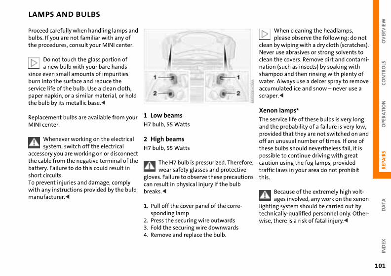
OV
ERV
IEW
OPE
RA
TIO
NC
ON
TRO
LS
LAMPS AND BULBS
When cleaning the headlamps, please observe the following: do not
by wiping with a dry cloth (scratches). r use abrasives or strong solvents to the covers. Remove dirt and contami-n (such as insects) by soaking with poo and then rinsing with plenty of r. Always use a deicer spray to remove
mulated ice and snow – never use a er.<
on lamps* ervice life of these bulbs is very long
the probability of a failure is very low, ided that they are not switched on and n unusual number of times. If one of
cleanNevecleannatioshamwateaccuscrap
XenThe sand provoff a
REP
AIR
SD
ATA
IND
EX
e bulbs should nevertheless fail, it is ible to continue driving with great ion using the fog lamps, provided ic laws in your area do not prohibit
Because of the extremely high volt-ages involved, any work on the xenon
ing system should be carried out by nically-qualified personnel only. Other-, there is a risk of fatal injury.<
re,
ns
thesposscauttraffthis.
lighttechwise
101
Proceed carefully when handling lamps and bulbs. If you are not familiar with any of the procedures, consult your MINI center.
Do not touch the glass portion of a new bulb with your bare hands
since even small amounts of impurities burn into the surface and reduce the service life of the bulb. Use a clean cloth, paper napkin, or a similar material, or hold the bulb by its metallic base.<
Replacement bulbs are available from your MINI center.
Whenever working on the electrical
1 Low beams H7 bulb, 55 Watts
2 High beams
system, switch off the electricalaccessory you are working on or disconnect the cable from the negative terminal of the battery. Failure to do this could result in short circuits.To prevent injuries and damage, comply with any instructions provided by the bulb manufacturer.<
H7 bulb, 55 Watts
The H7 bulb is pressurized. Therefowear safety glasses and protective
gloves. Failure to observe these precautiocan result in physical injury if the bulb breaks.<
1. Pull off the cover panel of the corre-sponding lamp
2. Press the securing wire outwards3. Fold the securing wire downwards4. Remove and replace the bulb.
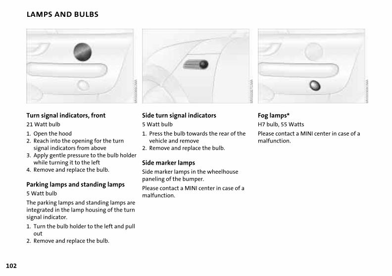
102
LAMPS AND BULBS
amps* lb, 55 Watts
e contact a MINI center in case of a nction.
Fog lH7 bu
Pleasmalfu
Turn signal indicators, front 21 Watt bulb
1. Open the hood2. Reach into the opening for the turn
Side turn signal indicators5 Watt bulb
1. Press the bulb towards the rear of the vehicle and remove
signal indicators from above3. Apply gentle pressure to the bulb holder
while turning it to the left4. Remove and replace the bulb.
Parking lamps and standing lamps 5 Watt bulb
The parking lamps and standing lamps are integrated in the lamp housing of the turn signal indicator.
1. Turn the bulb holder to the left and pull out
2. Remove and replace the bulb.
2. Remove and replace the bulb.
Side marker lampsSide marker lamps in the wheelhouse paneling of the bumper.
Please contact a MINI center in case of a malfunction.
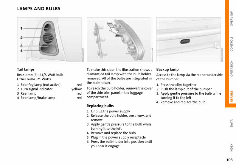
OV
ERV
IEW
OPE
RA
TIO
NC
ON
TRO
LS
LAMPS AND BULBS
up lampss to the lamp via the rear or underside e bumper.
ess the clips together
a r n
BackAcceof th
1. Pr
REP
AIR
SD
ATA
IND
EX
sh the lamp out of the bumperply gentle pressure to the bulb while
rning it to the leftmove and replace the bulb.
er
d
e
il
2. Pu3. Ap
tu4. Re
103
Tail lamps Rear lamp (3): 21/5 Watt bulbOther bulbs: 21 Watts
1 Rear fog lamp (not active) red
To make this clear, the illustration showsdismantled tail lamp with the bulb holderemoved. All of the bulbs are integrated ithe bulb holder.
2 Turn signal indicator yellow3 Rear lamp red4 Rear lamp/brake lamp red
To reach the bulb holder, remove the covof the side trim panel in the luggage compartment.
Replacing bulbs1. Unplug the power supply2. Release the bulb holder, see arrow, an
remove3. Apply gentle pressure to the bulb whil
turning it to the left4. Remove and replace the bulb5. Plug in the power supply receptacle6. Press the bulb holder into position unt
you hear it engage.

104
LAMPS AND BULBS
ior lampsor lamp (6 Watt xenon bulb)
ss out the lamp cover with a screw-ver
InterInteri
1. Predri
move and replace the bulb.
ng lamps (2 x 6 Watt xenon bulbs)
ss out the lamp cover with a screw-verscrew the entire lamp with a screw-vermove the bulb from above and lace.
2. Re
Readi
1. Predri
2. Undri
3. Rerep
Center (high-mount) brake lamp LED strip on the tailgate.
Please contact a MINI center in case of a malfunction.
License plate lamps 5 Watt bulb
1. Apply a screwdriver to the recess and lever out the lamp cover
2. Replace the bulb.
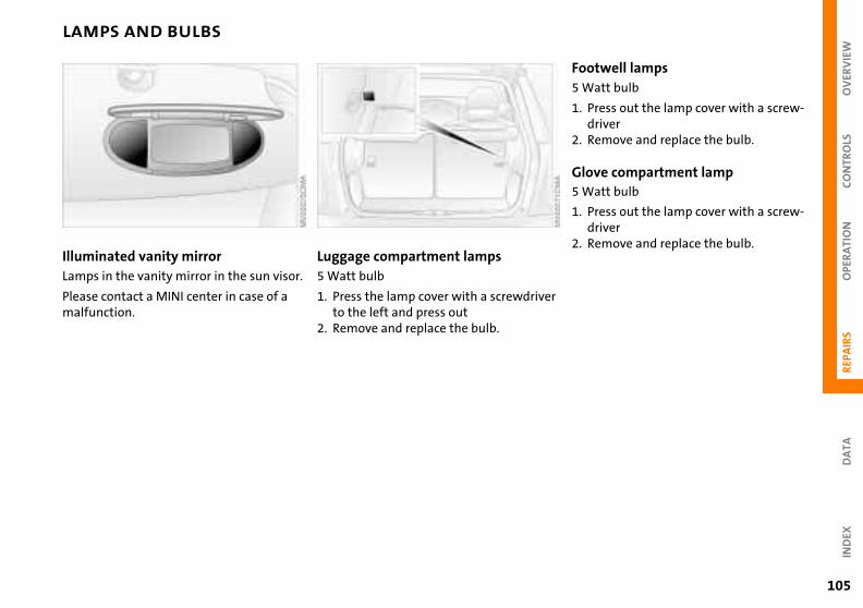
OV
ERV
IEW
OPE
RA
TIO
NC
ON
TRO
LS
LAMPS AND BULBS
well lampstt bulb
ess out the lamp cover with a screw-ivermove and replace the bulb.
e compartment lamptt bulb
ess out the lamp cover with a screw-ivermove and replace the bulb.
r
Foot5 Wa
1. Prdr
2. Re
Glov5 Wa
1. Prdr
2. Re
REP
AIR
SD
ATA
IND
EX
105
Illuminated vanity mirrorLamps in the vanity mirror in the sun visor.
Please contact a MINI center in case of a malfunction.
Luggage compartment lamps 5 Watt bulb
1. Press the lamp cover with a screwdriveto the left and press out
2. Remove and replace the bulb.
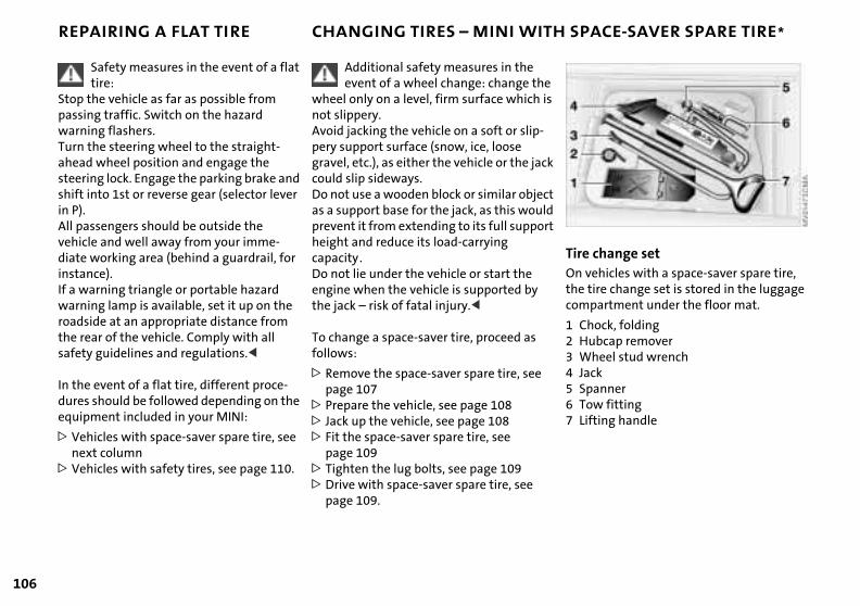
106
REPAIRING A FLAT TIRE CHANGING TIRES – MINI WITH SPACE-SAVER SPARE TIRE*
hange sethicles with a space-saver spare tire, re change set is stored in the luggage artment under the floor mat.
e s
k
t d rt
Tire cOn vethe ticomp
ock, foldingbcap removereel stud wrench
knner fitting
ing handle
1 Ch2 Hu3 Wh4 Jac5 Spa6 Tow7 Lift
Safety measures in the event of a flat tire:
Stop the vehicle as far as possible from passing traffic. Switch on the hazard warning flashers.Turn the steering wheel to the straight-ahead wheel position and engage the steering lock. Engage the parking brake and shift into 1st or reverse gear (selector lever in P).All passengers should be outside the vehicle and well away from your imme-diate working area (behind a guardrail, for instance).If a warning triangle or portable hazard warning lamp is available, set it up on the
Additional safety measures in the event of a wheel change: change th
wheel only on a level, firm surface which inot slippery.Avoid jacking the vehicle on a soft or slip-pery support surface (snow, ice, loose gravel, etc.), as either the vehicle or the jaccould slip sideways. Do not use a wooden block or similar objecas a support base for the jack, as this woulprevent it from extending to its full suppoheight and reduce its load-carrying capacity. Do not lie under the vehicle or start the engine when the vehicle is supported by the jack – risk of fatal injury.<
roadside at an appropriate distance from the rear of the vehicle. Comply with all safety guidelines and regulations.<
In the event of a flat tire, different proce-dures should be followed depending on the equipment included in your MINI:
> Vehicles with space-saver spare tire, see next column
> Vehicles with safety tires, see page 110.
To change a space-saver tire, proceed as follows:
> Remove the space-saver spare tire, see page 107
> Prepare the vehicle, see page 108> Jack up the vehicle, see page 108> Fit the space-saver spare tire, see
page 109> Tighten the lug bolts, see page 109>Drive with space-saver spare tire, see
page 109.
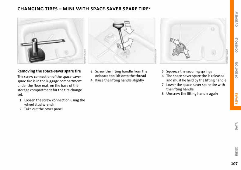
OV
ERV
IEW
REP
AIR
SO
PER
ATI
ON
CO
NTR
OLS
DA
TAN
DEX
CHANGING TIRES – MINI WITH SPACE-SAVER SPARE TIRE*
queeze the securing springshe space-saver spare tire is released nd must be held by the lifting handleower the space-saver spare tire with he lifting handlenscrew the lifting handle again
5. S6. T
a7. L
t8. U
107
I
Removing the space-saver spare tireThe screw connection of the space-saver spare tire is in the luggage compartment under the floor mat, on the base of the
3. Screw the lifting handle from the onboard tool kit onto the thread
4. Raise the lifting handle slightly
storage compartment for the tire change set.
1. Loosen the screw connection using the wheel stud wrench
2. Take out the cover panel
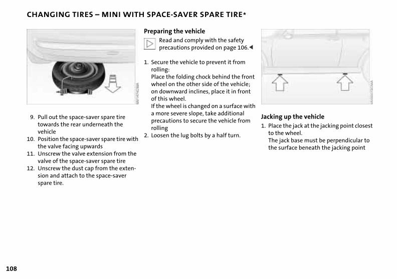
108
CHANGING TIRES – MINI WITH SPACE-SAVER SPARE TIRE*
ng up the vehiclece the jack at the jacking point closest the wheel.e jack base must be perpendicular to surface beneath the jacking point
t
h
Jacki1. Pla
to Ththe
9. Pull out the space-saver spare tire towards the rear underneath the vehicle
10. Position the space-saver spare tire with
Preparing the vehicleRead and comply with the safety precautions provided on page 106.<
1. Secure the vehicle to prevent it from rolling:Place the folding chock behind the fronwheel on the other side of the vehicle; on downward inclines, place it in front of this wheel. If the wheel is changed on a surface wita more severe slope, take additional precautions to secure the vehicle from rolling
2. Loosen the lug bolts by a half turn.
the valve facing upwards11. Unscrew the valve extension from the
valve of the space-saver spare tire12. Unscrew the dust cap from the exten-
sion and attach to the space-saver spare tire.
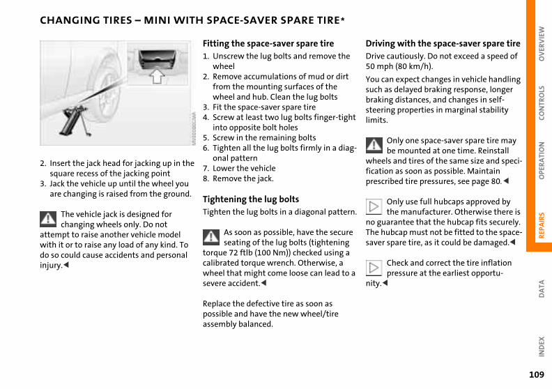
109
OV
ERV
IEW
REP
AIR
SO
PER
ATI
ON
CO
NTR
OLS
DA
TAIN
DEX
CHANGING TIRES – MINI WITH SPACE-SAVER SPARE TIRE*
ing with the space-saver spare tire cautiously. Do not exceed a speed of ph (80 km/h).
can expect changes in vehicle handling as delayed braking response, longer ing distances, and changes in self-ing properties in marginal stability s.
Only one space-saver spare tire may be mounted at one time. Reinstall
els and tires of the same size and speci-ion as soon as possible. Maintain ribed tire pressures, see page 80.<
Only use full hubcaps approved by the manufacturer. Otherwise there is
uarantee that the hubcap fits securely. ubcap must not be fitted to the space-
r spare tire, as it could be damaged.<
Check and correct the tire inflation pressure at the earliest opportu-<
t
g-
n.
e
a
DrivDrive50 m
You suchbraksteerlimit
wheficatpresc
no gThe hsave
nity.
2. Insert the jack head for jacking up in the square recess of the jacking point
3. Jack the vehicle up until the wheel you are changing is raised from the ground.
Fitting the space-saver spare tire1. Unscrew the lug bolts and remove the
wheel2. Remove accumulations of mud or dirt
from the mounting surfaces of the wheel and hub. Clean the lug bolts
3. Fit the space-saver spare tire4. Screw at least two lug bolts finger-tigh
into opposite bolt holes 5. Screw in the remaining bolts 6. Tighten all the lug bolts firmly in a dia
onal pattern7. Lower the vehicle8. Remove the jack.
Tightening the lug bolts
The vehicle jack is designed for changing wheels only. Do not
attempt to raise another vehicle model with it or to raise any load of any kind. To do so could cause accidents and personal injury.<
Tighten the lug bolts in a diagonal patter
As soon as possible, have the securseating of the lug bolts (tightening
torque 72 ftlb (100 Nm)) checked using acalibrated torque wrench. Otherwise, a wheel that might come loose can lead tosevere accident.<
Replace the defective tire as soon as possible and have the new wheel/tire assembly balanced.
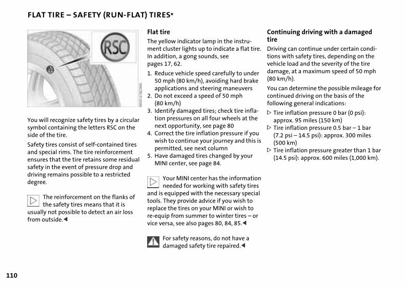
110
FLAT TIRE – SAFETY (RUN-FLAT) TIRES*
inuing driving with a damaged
g can continue under certain condi- with safety tires, depending on the le load and the severity of the tire ge, at a maximum speed of 50 mph
/h).
an determine the possible mileage for nued driving on the basis of the
ing general indications:
e inflation pressure 0 bar (0 psi): rox. 95 miles (150 km)
e inflation pressure 0.5 bar – 1 bar psi – 14.5 psi): approx. 300 miles
0 km)e inflation pressure greater than 1 bar .5 psi): approx. 600 miles (1,000 km).
e.
r
-
is
n l
ConttireDrivintionsvehicdama(80 km
You ccontifollow
> Tirapp
> Tir(7.2(50
> Tir(14
You will recognize safety tires by a circular symbol containing the letters RSC on the side of the tire.
Safety tires consist of self-contained tires
Flat tire The yellow indicator lamp in the instru-ment cluster lights up to indicate a flat tirIn addition, a gong sounds, see pages 17, 62.
1. Reduce vehicle speed carefully to unde50 mph (80 km/h), avoiding hard brakeapplications and steering maneuvers
2. Do not exceed a speed of 50 mph (80 km/h)
3. Identify damaged tires; check tire inflation pressures on all four wheels at thenext opportunity, see page 80
4. Correct the tire inflation pressure if youwish to continue your journey and this
and special rims. The tire reinforcement ensures that the tire retains some residual safety in the event of pressure drop and driving remains possible to a restricted degree.
The reinforcement on the flanks of the safety tires means that it is
usually not possible to detect an air loss from outside.<
permitted, see next column5. Have damaged tires changed by your
MINI center, see page 84.
Your MINI center has the informationeeded for working with safety tires
and is equipped with the necessary speciatools. They provide advice if you wish to replace the tires on your MINI or wish to re-equip from summer to winter tires – orvice versa, see also pages 80, 84, 85.<
For safety reasons, do not have a damaged safety tire repaired.<
OV
ERV
IEW
REP
AIR
SO
PER
ATI
ON
CO
NTR
OLS
DA
TA
BATTERY
e, lly er
t
l
ds
s-
IND
EX
111
Location in the MINI COOPERThe battery is located in the engine compartment.
Exact location, see page 87.
Location in the MINI COOPER SThe battery is located in the luggage compartment under the floor mat.
Battery careThe battery is absolutely maintenance-frethat is, the original electrolyte will normalast for the service life of the battery undmoderate climatic conditions.
For all questions regarding the battery, please consult your MINI
center. <
Charging the battery Only charge the battery in the vehicle viathe terminals in the engine compartmenwith the engine switched off, see "Jump-starting" on page 113.
Whenever working on the electricasystem, disconnect the cable from
the negative terminal of the battery. Failure to do this could result in fire hazaror injury due to short circuits.<
Return used batteries to a recyclingpoint or your MINI center. Maintain
the battery in an upright position for tranport and storage. Secure the battery to prevent it from tilting during transport.<
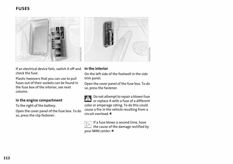
112
FUSES
o
e t
If an electrical device fails, switch it off and check the fuse.
Plastic tweezers that you can use to pull fuses out of their sockets can be found in
In the interiorOn the left side of the footwell in the sidetrim panel.
Open the cover panel of the fuse box. To d
the fuse box of the interior, see next column.In the engine compartmentTo the right of the battery.
Open the cover panel of the fuse box. To do so, press the clip fastener.
so, press the fastener.
Do not attempt to repair a blown fusor replace it with a fuse of a differen
color or amperage rating. To do this couldcause a fire in the vehicle resulting from acircuit overload.<
If a fuse blows a second time, have the cause of the damage rectified by
your MINI center.<
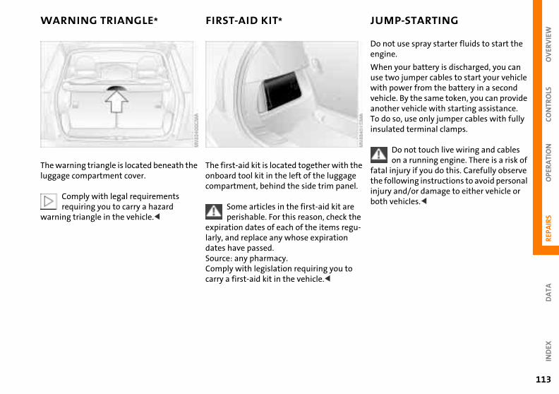
OV
ERV
IEW
OPE
RA
TIO
NC
ON
TRO
LS
WARNING TRIANGLE* FIRST-AID KIT* JUMP-STARTING
ot use spray starter fluids to start the ne.
n your battery is discharged, you can wo jumper cables to start your vehicle power from the battery in a second le. By the same token, you can provide
her vehicle with starting assistance. so, use only jumper cables with fully
ated terminal clamps.
Do not touch live wiring and cables on a running engine. There is a risk of
injury if you do this. Carefully observe ollowing instructions to avoid personal y and/or damage to either vehicle or vehicles.<
he
l.
Do nengi
Wheuse twithvehicanotTo doinsul
fatalthe finjurboth
REP
AIR
SD
ATA
IND
EX
e
u-
113
The warning triangle is located beneath the luggage compartment cover.
Comply with legal requirements
The first-aid kit is located together with tonboard tool kit in the left of the luggagecompartment, behind the side trim pane
requiring you to carry a hazard warning triangle in the vehicle.<
Some articles in the first-aid kit areperishable. For this reason, check th
expiration dates of each of the items reglarly, and replace any whose expiration dates have passed. Source: any pharmacy.Comply with legislation requiring you to carry a first-aid kit in the vehicle.<

114
JUMP-STARTING
rming the jump-startrt the engine of the vehicle providing current and allow to run at a fast idle
eed for several minutes rt the engine on the vehicle with the charged battery in the usual manner. If the first start attempt is not successful, wait a few minutes before another attempt in order to allow the discharged battery to recharge.
On the MINI:Before disconnecting the jumper
s, switch on the lighting, rear window ster and the highest blower speed as s the engine for at least approx.
,
Perfo1. Sta
thesp
2. Stadis>
cabledefrowell a
conds to prevent a voltage surge from gulator to the electrical systems and onents.<
en disconnect the jumper cables in reverse order.
Depending on the cause of the malfunction, have the battery ed and recharged at your MINI r.<
al e
e
e eo
f I,
10 sethe recomp
3. Ththe
checkcente
Preparation for jump-starting1. Check whether the battery of the support
vehicle has 12 Volts and approximately the same capacity (Ah) (printed on the battery)
2. Switch off the engine of the support vehicle
3. Switch off any electrical systems and components in both vehicles – except for the hazard warning flashers of the support vehicle.>Do not disconnect the discharged
battery from the vehicle electrical system
>Make certain that there is no contact between the bodywork of the two
1. On the MINI COOPER S, the positive terminal connection (for jump-starting)see arrow 1, functions as the positive battery terminal.
vehicles – short circuit hazard!4. With the battery of the MINI COOPER,
remove the cover panel. To do so, press both clips at the same time or with the MINI COOPER S, open the cover of the positive terminal connection (for jump-starting)*, see arrow 1.
Connect the jumper cablesAdhere to the sequence also when providing support for other vehicles;
failure to observe this procedure can lead to sparks at the terminals and pose an injury hazard.<
Use the jumper cable (+) to set up a connection between the positive terminof the discharged battery and the positivterminal of the support battery
2. Use the second jumper cable (–) to set up the connection between the negativterminals of both vehicles. To do so:> Connect one terminal clamp to the
negative terminal and/or to an enginor body ground of the support vehicl
> Connect the second terminal clamp tthe negative terminal of the battery and/or to an engine or body ground othe vehicle to be started. For the MINsee arrow 2.
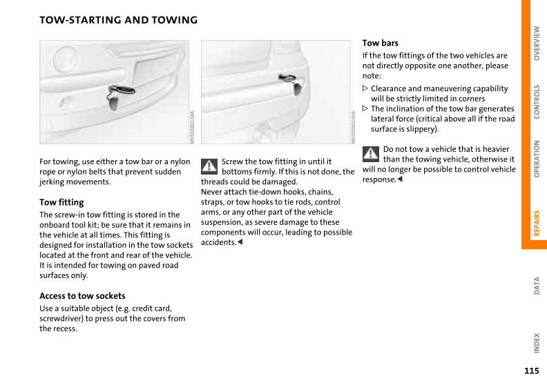
OV
ERV
IEW
REP
AIR
SO
PER
ATI
ON
CO
NTR
OLS
TOW-STARTING AND TOWING
bars tow fittings of the two vehicles are irectly opposite one another, please
:
earance and maneuvering capability ll be strictly limited in cornerse inclination of the tow bar generates eral force (critical above all if the road rface is slippery).
Do not tow a vehicle that is heavier than the towing vehicle, otherwise it o longer be possible to control vehicle nse.<
he
le
TowIf thenot dnote
> Clwi
> Thlatsu
will nrespo
DA
TAIN
DEX
115
For towing, use either a tow bar or a nylon rope or nylon belts that prevent sudden jerking movements.
Screw the tow fitting in until it bottoms firmly. If this is not done, t
threads could be damaged.Never attach tie-down hooks, chains,
Tow fittingThe screw-in tow fitting is stored in the onboard tool kit; be sure that it remains in the vehicle at all times. This fitting is designed for installation in the tow sockets located at the front and rear of the vehicle. It is intended for towing on paved road surfaces only.
Access to tow socketsUse a suitable object (e.g. credit card, screwdriver) to press out the covers from the recess.
straps, or tow hooks to tie rods, control arms, or any other part of the vehicle suspension, as severe damage to these components will occur, leading to possibaccidents.<
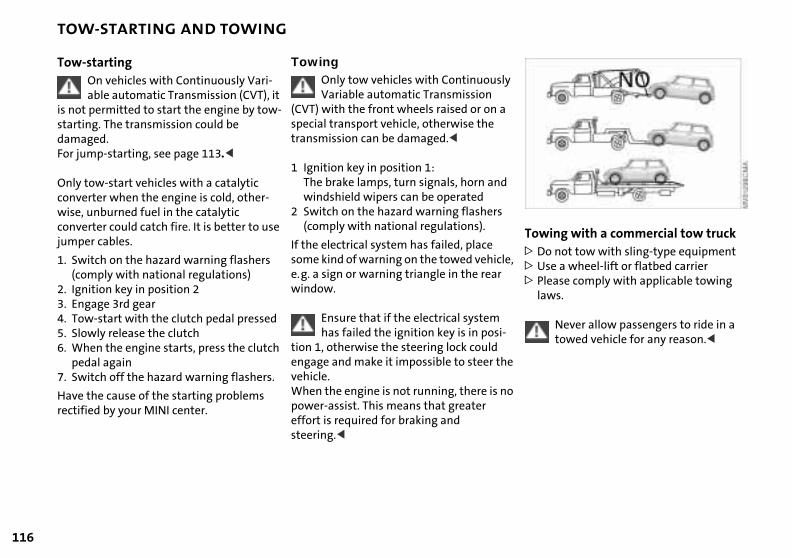
116
TOW-STARTING AND TOWING
ing with a commercial tow truck not tow with sling-type equipment e a wheel-lift or flatbed carrier ase comply with applicable towing s.
Never allow passengers to ride in a towed vehicle for any reason.<
ly
d
le,
-
he
Tow>Do>Us> Ple
law
o
Tow-startingOn vehicles with Continuously Vari-able automatic Transmission (CVT), it
is not permitted to start the engine by tow-starting. The transmission could be damaged.For jump-starting, see page 113.<
Only tow-start vehicles with a catalytic converter when the engine is cold, other-wise, unburned fuel in the catalytic converter could catch fire. It is better to use jumper cables.
1. Switch on the hazard warning flashers(comply with national regulations)
2. Ignition key in position 2
TowingOnly tow vehicles with ContinuousVariable automatic Transmission
(CVT) with the front wheels raised or on aspecial transport vehicle, otherwise the transmission can be damaged.<
1 Ignition key in position 1:The brake lamps, turn signals, horn anwindshield wipers can be operated
2 Switch on the hazard warning flashers(comply with national regulations).
If the electrical system has failed, place some kind of warning on the towed vehice.g. a sign or warning triangle in the rearwindow.
3. Engage 3rd gear4. Tow-start with the clutch pedal pressed5. Slowly release the clutch 6. When the engine starts, press the clutch
pedal again7. Switch off the hazard warning flashers.
Have the cause of the starting problems rectified by your MINI center.
Ensure that if the electrical system has failed the ignition key is in posi
tion 1, otherwise the steering lock could engage and make it impossible to steer tvehicle.When the engine is not running, there is npower-assist. This means that greater effort is required for braking and steering.<

OV
ERV
IEW
OPE
RA
TIO
NC
ON
TRO
LS
REPA
IRS
DA
TAIN
DEX
117

118
OVERVIEW
CONTROLS
OPERATION, CARE, MAINTENANCE
OWNER SERVICE PROCEDURES
OV
ERV
IEW
REP
AIR
SO
PER
ATI
ON
CO
NTR
OLS
INDEX
TECHNICAL DATA
119
DA
TAIN
DEX
Data
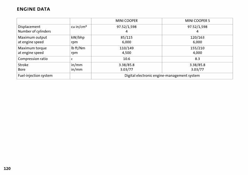
120
ENGINE DATA
MINI COOPER S
97.52/1,5984
120/1636,000
155/2104,000
8.3
3.38/85.83.03/77
agement system
gine-manMINI COOPER
DisplacementNumber of cylinders
cu in/cmm 97.52/1,5984
Maximum outputat engine speed
kW/bhp rpm
85/1156,000
Maximum torqueat engine speed
lb ft/Nm rpm
110/1494,500
Compression ratio e 10.6
StrokeBore
in/mm in/mm
3.38/85.83.03/77
Fuel-injection system Digital electronic en
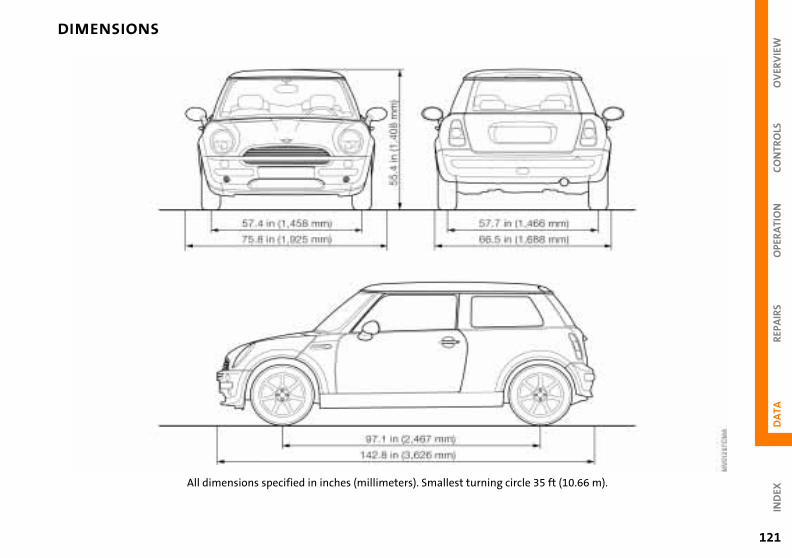
121
OV
ERV
IEW
REP
AIR
SO
PER
ATI
ON
CO
NTR
OLS
DA
TAIN
DEX
DIMENSIONS
ft (10.66 m).
circle 35 All dimensions specified in inches (millimeters). Smallest turning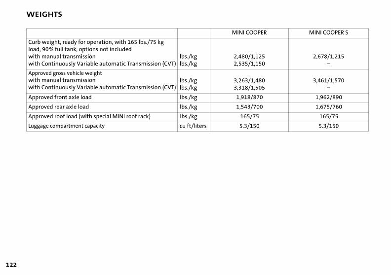
122
WEIGHTS
MINI COOPER S
2,678/1,215–
3,461/1,570–
1,962/890
1,675/760
165/75
5.3/150
OOPER
/1,125/1,150
/1,480/1,505
8/870
3/700
/75
/150
MINI C
Curb weight, ready for operation, with 165 lbs./75 kg load, 90% full tank, options not includedwith manual transmissionwith Continuously Variable automatic Transmission (CVT)
lbs./kglbs./kg
2,4802,535
Approved gross vehicle weightwith manual transmissionwith Continuously Variable automatic Transmission (CVT)
lbs./kglbs./kg
3,2633,318
Approved front axle load lbs./kg 1,91
Approved rear axle load lbs./kg 1,54
Approved roof load (with special MINI roof rack) lbs./kg 165
Luggage compartment capacity cu ft/liters 5.3
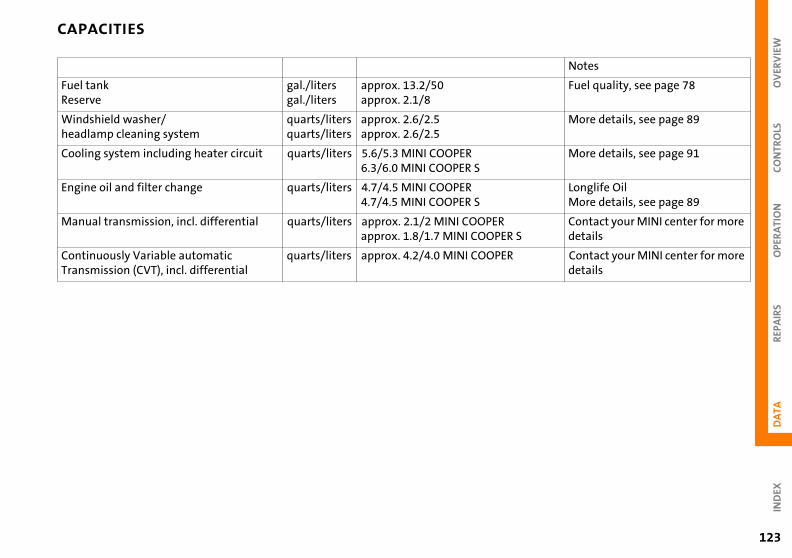
123
OV
ERV
IEW
REP
AIR
SO
PER
ATI
ON
CO
NTR
OLS
DA
TAIN
DEX
CAPACITIES
Notes
Fuel quality, see page 78
More details, see page 89
More details, see page 91
Longlife OilMore details, see page 89
Contact your MINI center for more details
Contact your MINI center for more details
ER S
ER
Fuel tankReserve
gal./litersgal./liters
approx. 13.2/50approx. 2.1/8
Windshield washer/ headlamp cleaning system
quarts/litersquarts/liters
approx. 2.6/2.5approx. 2.6/2.5
Cooling system including heater circuit quarts/liters 5.6/5.3 MINI COOPER6.3/6.0 MINI COOPER S
Engine oil and filter change quarts/liters 4.7/4.5 MINI COOPER4.7/4.5 MINI COOPER S
Manual transmission, incl. differential quarts/liters approx. 2.1/2 MINI COOPERapprox. 1.8/1.7 MINI COOP
Continuously Variable automatic Transmission (CVT), incl. differential
quarts/liters approx. 4.2/4.0 MINI COOP

124
ELECTRICAL SYSTEM
le
Battery 12V, 55 AhSpark plugs NGK BKR 6 EQUP
Original MINI parts and accessories as well as qualified advice is availab
at your MINI center.<

OV
ERV
IEW
OPE
RA
TIO
NC
ON
TRO
LS
REPA
IRS
DA
TAIN
DEX
125
126

OVERVIEW
CONTROLS
OPERATION, CARE, MAINTENANCE
OWNER SERVICE PROCEDURES
INDEX
TECHNICAL DATA
127
OV
ERV
IEW
REP
AIR
SO
PER
ATI
ON
CO
NTR
OLS
DA
TAIN
DEX
Index
EVERYTHING FROM A TO Z
128
A ABS
SyActiAdju
basestth
Air cauco
Air cAir d
aiauco
Air pAir rAir s
aiauco
Air Air,AirbAll-Ant
3
103
4, 1
Break-in procedure 76 Breaking in the vehicle 76 Bridging 113, 114 Bulb replacement 101
backup lamps 103 brake lamp, third 104 footwell lamps 105 front fog lamps 102 front turn signal indicators 102 glove compartment lamp 105
Hilfsrahmen für Querverweise
(Antilock Brake stem) 16, 17, 78
vated-charcoal filter 69 sting ckrest 33 ats 31 eering wheel 35 igh support 33 onditioner operation 65 tomatic climate
Antifreeze 91 Antilock Brake System
(ABS) 16, 17, 78 Aquaplaning 76 ASC+T (Automatic Stability
Control plus Traction) 16, 17, 60
Ashtray 70 Automatic air distribution 68 Automatic air supply 68 Automatic car wash 94 Automatic cruise control 53
B Backrest, adjusting 3Backup lamps 45
bulb replacementBar, towing 115 Battery 111, 113, 11
capacity 124 charge current 15 charging 111 maintenance 111
Battery changing
ntrol 6onditioistributr condittomatintrol 6ressureecirculaupply r condittomatintrol 6
ol 22
7 9, 92
15
103
high beams 101 interior lamps 104 license plate lamp 104 low beams 101 luggage compartment lamps 105 parking lamps 102 rear lamps 103 side turn signal indicators 102 standing lamps 102
8 ner system 64 ion ioner system 65 c climate 8, 69
80 tion 65, 68
ioner system 65 c climate 9
Automatic dimming of interior rearview mirror 37
Automatic program, see Automatic air distribution 68
Automatic Stability Control plus Traction (ASC+T) 16, 17, 60
Average fuel consumption 59 Average speed 59 Axle loads 122
remote control 22 Battery, remote contrBeverage holder 70 Blower 65, 69 BMW 6 Bore 120 Brake 16 Brake fluid change 5Brake fluid level 15, 7Brake hydraulic systemBrake lamp
bulb replacement
tail lamps 103 vanity mirror 105vents 66, 69 dry 65, 68 ags 16, 31, 37
season tires 85 enna 94
Brake pads 76, 79 Brake rotors 76 Brake system 76, 79
brake fluid 92 Brakes 79
24

EVERYTHING FROM A TO Z
OV
ERV
IEW
TIO
NC
ON
TRO
LS
C Ca
Ca
CaCaCa
Ca
Ca
re
55
e ission
Control elements 12 Convenience feature
sliding/tilt sunroof 25 windows 25
Convenience operation via central locking system 26
Coolant 91 Coolant level 91 Coolant temperature
gauge 56 Cooling 65, 68
lifornia Proposition 65 Warning 97 n holder, see Beverage holder 70 r wash 94 r-care products 94 re chrome parts 94 floor mats 95 imitation leather 95 leather 95
CD player, see separate Owner's Manual
Center (high-mount) brake lamp bulb replacement 104
Central locking system 23, 26 Changing tires
space-saver spare tire 106 Child seat 38 Child-restraint systems 38 Chrome parts 94 Cigarette lighter 70
Computer 58 average fuel consumption 59 average speed 59cruising range 59 exterior temperatu
Condensation 65, 68Consumption 59 Consumption displayContents 2 Continuously Variabl
automatic Transm
REP
AIR
SO
PER
A
lightof upplasrubbsafespecwindrgosecustowring
sion ) 48
Copyright notice 6 Correct sitting posture with
airbags 31 safety belt 31
Cruise control 17, 18, 53 Cruising range 59 Cup holder, see Beverage
holder 70 Curb weight 122 Currency of the Owner's
Manual 7 Cylinders 120
-alloy wheels 94 holstery 94
tic parts 95 er parts 95
ty belts 95 ial parts 94 shield wipers 95 72
ring 72 ing 72
for your vehicle 94 te player, see separate
socket 70 Cleaning rear window 52 Cleaning windshield 52 Clock 58 Closing
from inside 26 from outside 23
Clothes hooks 77 Clutch 76 Cockpit 12 Combination of wheels/
tires 84
(CVT) electronic transmiscontrol module (EPgear display 48 ignition 42 interlock 42 manual mode 47 parking 47 reverse gear 47 selector lever shiftlock 42, 46 shiftlock 46
129
DA
TAIN
DEX
48
CassetOwner's Manual
CD changer, see separate Owner's Manual
Compact Disc player, see separate Owner's Manual
Compression ratio 120
Sport program 47Steptronic 46 towing 116 tow-starting 116 transmission fault
59
EVERYTHING FROM A TO Z
130
n cuou
48
30
F Failure, tires 62, 106, 110 Filler cap cover 77 Filling capacities 123 Filling, tank 123 First-aid kit 113 Flat tire 62, 106 Flat Tire Monitor 16, 17, 62 Floor carpets 95 Floor coverings 95 Floor mats 95
D Dashboard 12 Data
dimensions 121 engine 120 weights 122
Data, technical 120 Daytime driving lamps 49 Decommissioning the
vehicle 96 Deep water, see Water on
Display lighting 50 Distance remaining 59 Door keys 22 Doors
locking 24 manual operation 25 remote control 23 unlocking 24
DOT Quality Grades 83 Drink holder, see Beverage
holder 70 Driving lamps 49
Electronic transmissiomodule (EP), ContinVariable automaticTransmission (CVT)
Emergency operationdriver's door 25 sliding/tilt sunrooftailgate 27
Engine 76 electronics 17 power output 17 speed 17, 55
ssion
Fog lamps 50 Foldable rear backrest 71 "Follow me home" lamps 49 Footbrake 79 Footwell lamps
bulb replacement 105 Front fog lamps 50
bulb replacement 102 Front seat adjustment 31 Fuel consumption 59 Fuel consumption display 55 Fuel gauge 55
roadways 77 Defrosting position 66 Defrosting windows 69
air conditioner system 66 automatic climate control 69
Dimensions 121 Dirt on the paintwork 94 Disc brakes 79 Displacement 120 Display elements 13, 14
coolant temperature
Driving notes, general 76 Dry air 65, 68 Dynamic Stability Control
(DSC) 16, 61
E Easy Entry 33 EBV (Electronic Brake Force
Distribution) 16 Electric power windows 28 Electrical defect
starting 42 switching off 43
Engine compartment MINI COOPER 87 MINI COOPER S 88
Engine oil 89 additives 90 prescribed oils 90 pressure 15
Entry to the rear 33 EP (electronic transmi
le sion
4
Fuel preparation 120 Fuel quality 78 Fuel reserve indicator 55 Fuel tank capacity 123 Fuses 112
gauge 56 fuel gauge 55 indicator and warning lamps 15 odometer 55 Service Interval Display 57 with navigation system 14
driver's door 25 sliding/tilt sunroof 30
Electrical system 124 Electronic Brake Force
Distribution (EBV) 16
control module), Continuously Variabautomatic Transmis(CVT) 48
Exterior finish, care 9Exterior mirrors 36 Eyelets, towing 115
ontrol sly
EVERYTHING FROM A TO Z
OV
ERV
IEW
TIO
NC
ON
TRO
LS
G GasolinGasolinGear di
Contautom(CVT)
GeneraGlove cGlove c
bulb GrGr
H HaHaHeHeHe
HeH
10rorg 3
114
interior lamps 50, 104 license plate lamp 104 low beams 49, 101 luggage compartment lamps 105 parking lamps 49, 102 reading lamps 50 rear fog lamp 103 standing lamps 49, 102 tail lamp 103 turn signal indicators 102 xenon lamps 101
e 78 e gauge 55 splay 48 inuously Variable
atic Transmission 48
l driving notes 76 ompartment 70 ompartment lamps replacement 105 66, 69
Heated outside mirrors 36 rear window 65, 68 seats 34 windshield 65, 68 windshield washer jets 52
Heavy cargo 72 Height 121 High beams 17, 49
bulb replacement 101 Hood 16, 86 Horn 12
Interior lamps 50 bulb replacement
Interior rearview mirautomatic dimmin
Interlock 42 Interval display 93
J Jack 100, 106 Jump-starting 113,
REP
AIR
SO
PER
A
ring
04
ps 49
Lashing eyes 72 LATCH child-restraint
system 41 Leather care 95 LED light-emitting diodes 51 Length 121 License plate lamp
bulb replacement 104 Light-alloy wheels 94 "Lights on" warning 49 Loading 72 Load-securing devices 72
illesoss weight 122
ndbrake 44 zard warning flashers 12 ad airbags 37 ad restraints 34 adlamp cleaning
system 52, 89 filling 89 adlamp flasher 49
Hubcap remover 100, 106
I Ignition lock 42 Illuminated vanity mirror 36 Imitation leather 95 Imprint 6 Indicator lamps 15 Individual air distribution 69 INSPECTION 57 Instrument cluster, see Display
elements 13
K Keys 22
multifunction steewheel 18
Kickdown 47
L Lamps 49, 101
backup lamps 103brake lamp 103, 1daytime driving lamfog lamps 50
131
DA
TAIN
DEX
5 2
t 105
50
Low beams 49 bulb replacement 101
Luggage compartment 72 content 122
eadlamps care 94, 101 cleaning 52
Instrument lighting 50 Instrument panel 12 Interface socket
for Onboard Diagnostics 96
footwell lamps 10front fog lamps 10glove compartmenhigh beams 101 instrument lighting
4 36 7

EVERYTHING FROM A TO Z
132
e Slet nd
et
Power supply 12 V 70 Power windows 28 Pressure, tires 80, 109
Q Quality Grading, tire 83
R Radiator 91 Radio, see separate Owner's
Manual
Luggage compartment cover 71
Luggage compartment lamp bulb replacement 105
Luggage rack see Roof-mounted luggage rack 73
Lumbar support 32
M M+S tires 85
MINI Maintenance System 93 MINI manufacturer 6 MINI Mobility System 100 Mirrors 36 Mobility System, see MINI
Mobility System 100 Modifications, technical 96 Multifunction steering wheel
(MFL) 18 Multifunction switch 49
Oil change intervals, seand Warranty Bookmodels)/Warranty aService Guide Bookl(Canadian models)
Oil service 57 Old batteries 111 Onboard tool kit 100Opening
from inside 26 from outside 23
Outside temperature
age 71
(PDC) 63
102 ams 49
Rain sensor 51 Reading lamps 50 Rear backrest
foldable 71 Rear fog lamp 50
bulb replacement 103 Rear lamps 45, 103 Rear window defroster
automatic climate control 68 heating and climate control 65
Maintenance 57, 93 Maintenance System 93 Manual operation
driver's door 25 sliding/tilt sunroof 30 tailgate 27
Manual transmission 45 Manufacturer 6 Master key 22
initialization 22 MD player, see separate
Owner's Manual
N Navigation system, see
separate Owner's Manual 14
Non-smoker's equipment package, see Cigarette lighter socket 70
Nozzles 66, 69
O OBD interface socket 96 Odometer 55
display 59
P Package tray, see Lugg
compartment coverPark Distance Control Parking brake 16, 44Parking lamps 49
bulb replacementParking lamps/Low beParking, vehicle 76
MecMFL
wMicMin
O
ntrol) 63
0
Rear window wiper 52 replacing 100
Rearview mirror 36 Recirculated-air mode
air contitioner system 65 automatic climate control 68
hanical key 22 (Multifunction steering heel) 18 rofilter 66, 69 i Disc player, see separate wner's Manual
Oil 89 additives 90 level 15 prescribed oils 90 pressure 15
PDC (Park Distance CoPlastic 95 Pollen 66 Pollen filter 69 Power output 17, 12
ervice (US
EVERYTHING FROM A TO Z
OV
ERV
IEW
TIO
NC
ON
TRO
LS
RecirculatReclining sRefuelingRemaining
serviceRemote co
batterybattery initializa
Removingwindow
Reaac
ReReReReRoRo
bRuRu
t
1
10
, 114, 115
Technical data 120 Technical modifications 96 Temperature
automatic climate control 68 heating and climate control 65 tires 83
Temperature display 59 engine coolant 56
Temperature layering 66, 69 Temperatures, high 77
ion of air 65, 68 eat 31 77 distance for 57 ntrol 23 22
changing 22 tion 22
mist, s 66, 69 window mist
S Safety belts 16, 31, 35, 95
adjusting 35 Safety lock buttons 26 Safety tires 80, 84, 110
winter tires 84, 85 Screwdriver 100 Seats 31 Securing cargo 72 Selector lever shiftlock 42, 46 Service and Warranty Booklet
(US models)/Warranty and
Spare key 22 Spark plugs 124 Speed 120 Speeds 85 Split rear backrest 7Spray jets 52 Standing lamps 49
bulb replacementStarting 42
problems 43, 113with a discharged battery 113, 114
REP
AIR
SO
PER
A
43
103
The right tires 84 Third brake lamp
bulb replacement 104 Tire change
tire change set 106 Tire changes between axles 84 Tire failure 16
safety tires 110 space-saver spare tire 106
Tire inflation pressure 80, 85 Tires 80
all-season tires 85
movingir conditioner system 66 utomatic climate ontrol 69
placement key 22 porting safety defects 9 straint system 38 verse gear 45, 47 d antenna 94 ller sun blind, rear window lind 30
bber parts 95 n-flat tire, see Safety
Service Guide Booklet (Canadian models) 93
Service Interval Display 57, 93 Shiftlock 46 Side airbags 37 Side turn signal indicators
bulb replacement 102 Sitting 31 Sliding/tilt sunroof 29
convenience feature 25 safety function 30
Smoker's equipment
Steering lock 42 Storage, tires 84 Sun visors 36 Switches 12 Switching off, engineSymbols 6
T Tachometer 55 Tail lamps
bulb replacementTailgate 16, 27
133
DA
TAIN
DEX
27 break-in 76 changing 106 condition 82, 85 damage 82
ires 80, 84, 85, 110 package 70 Snow chains 85 Space-saver spare tire
changing tires 106
manual unlockingTank capacity 77 Tank content, filling
capacities 123
2

EVERYTHING FROM A TO Z
134
inflation prM+S tiresreplacemesafety tiressnow chainstorage 84temperatuthe right chtread 82 winter tirewith emergproperties,tires 80, 8
Tools 100 Torque 120 Tow bar 115Tow fittingTow socket fo
fittings 11Towing 115
with bar 1with Contiautomatic (CV
Towin
105
96
Wheel and tire combinations 84
Wheel stud wrench 100, 106, 107
Wheelbase 121 Width 121 Windows, convenience
feature 25 Windshield heating
automatic climate control 68 heating and climate
essure 80 85
nt 83 80, 84, 85, 110
s 85
re 83 oice 84
s 85 ency running
see Safety
Tow-starting 115, 116 with Continuously Variable automatic Transmission (CVT) 116
Tow-starting and towing 115 Traction 83 Trailer nose weight 122 Transmission 45 Transmission fault,
Continuously Variable automatic Transmission (CVT) 48
V Vanity mirror 36
bulb replacementilluminated 36
Vehicle battery 124 decommissioningdimensions 121 exterior finish 94 operating 42 settings 41
4
1
r5
1
nT
51
control 65 Windshield washer
system 51, 89 filling 89
Windshield wipers 51, 100 care 95 replacing 100
Winter tires 85 all-season tires 85 safety tires 84, 85
Wiper/washer system 51
, 85, 110
15 tow
5 uously Variable ransmission
Transporting children safely 38
Tread wear 83 Trip odometer 55 Turn signal indicators 17, 49
bulb replacement 102
U Uniform Tire Quality
Grading 83
washing 94 weight 122
Vehicle Memory 41 Ventilation 66
draft-free 66, 69
W Warning lamp 15 Warning triangle 113Washer systems 89 Washer/wiper systemWaste container 70
6, 35
Work in the engine compartment 86
T) 116 g eyelets 115
Water on roadways deep water 77
Wearing safety belt 1Weights 122

EVERYTHING FROM A TO Z
OV
ERV
IEW
TIO
NC
ON
TRO
LS
X Xenon lamps 101
REP
AIR
SO
PER
A
135
DA
TAIN
DEX
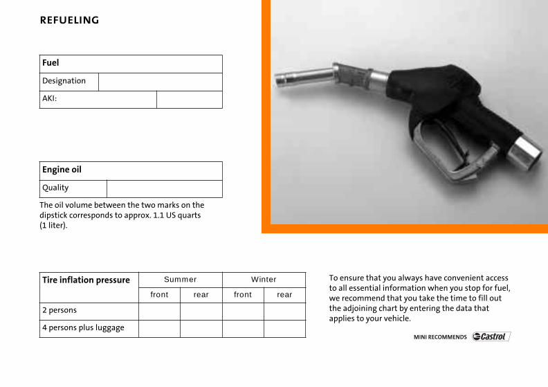
REFUELING
The oil volume between the two marks on the dipstick corresponds to approx. 1.1 US quarts (1 liter).
Fuel
Designation
AKI:
Engine oil
Quality
Tire inflation pressure Summer Winter
front rear front rear
2 persons
4 p e
To ensure that you always have convenient access to all essential information when you stop for fuel, we recommend that you take the time to fill out the adjoining chart by entering the data that applies to your vehicle.
ersons plus luggag

DRIVE ME.
0141
015
672
4u
e

MIN
I US-
En


![F RELAY LOCATIONS [Engine Compartment]](https://static.fdocuments.us/doc/165x107/625490974bba8c23495f7c32/f-relay-locations-engine-compartment.jpg)


![Position of Parts in Engine Compartment [2UZ-FE] · 2017. 3. 28. · 2003 4RUNNER (EWD514U) 32 G ELECTRICAL WIRING ROUTING Position of Parts in Engine Compartment [2UZ-FE] A 1 A/C](https://static.fdocuments.us/doc/165x107/61486fb32918e2056c22b020/position-of-parts-in-engine-compartment-2uz-fe-2017-3-28-2003-4runner-ewd514u.jpg)