Owners Manual · an c o tb erf i, s - rofi ted. ... the use of features and functions for exam-ple....
290
VOLVO C30 Owners Manual WEB EDITION
Transcript of Owners Manual · an c o tb erf i, s - rofi ted. ... the use of features and functions for exam-ple....

C30; 7; 3 2008-03-04T12:22:14+01:00; Page 1evastarck
VOLVO C30
Owners Manual
WEB EDITION

DEAR VOLVO OWNERTHANK YOU FOR CHOOSING VOLVO
We hope you will enjoy many years of driving pleasure in yourVolvo. The car has been designed for the safety and comfort ofyou and your passengers. Volvo is one of the safest cars in theworld. Your Volvo has also been designed to satisfy all currentsafety and environmental requirements.
In order to increase your enjoyment of the car, we recommendthat you familiarise yourself with the equipment, instructionsand maintenance information contained in this owner's manual.
C30; 7; 3 2008-03-04T12:19:30+01:00; Page 1evastarck

Table of contents
2 * Option/accessory, for more information, see Introduction.
0000 IntroductionImportant information................................. 8Volvo and the environment....................... 11
0101 SafetySeatbelts................................................... 16Airbag system........................................... 19Airbags (SRS)............................................ 20Activating/deactivating the airbag (SRS)*. 23Side airbags (SIPS bags).......................... 25Inflatable Curtain (IC)................................ 27WHIPS....................................................... 28When the systems deploy......................... 30Crash mode.............................................. 31Child safety............................................... 32 02
02 Instruments and controlsOverview, left-hand drive cars.................. 38Overview, right-hand drive cars................ 40Driver's door control panel....................... 42Combined instrument panel...................... 43Indicator and warning symbols................. 44Information display................................... 48Electrical socket........................................ 50Lighting panel........................................... 51Left-hand stalk switch............................... 53Right-hand stalk switch............................ 56Cruise control*.......................................... 59Keypad in the steering wheel*.................. 61Steering wheel adjustment, hazard warn-ing flashers................................................ 62Parking brake............................................ 63Power windows......................................... 64Rearview and door mirrors....................... 66Power sunroof*......................................... 70Personal preferences................................ 71
HomeLink EU*......................................... 74
C30; 7; 3 2008-03-04T12:19:30+01:00; Page 2evastarck

Table of contents
* Option/accessory, for more information, see Introduction. 3
0303 Climate controlGeneral information on climate control..... 80Manual climate control, AC....................... 82Electronic climate control, ECC*............... 85Air distribution........................................... 89Fuel-driven engine block heater and pas-senger compartment heater*.................... 90Fuel-driven auxiliary heater* (diesel)......... 93
0404 InteriorFront seats................................................ 96Interior lighting.......................................... 99Storage spaces in the passenger com-partment.................................................. 102Rear seat................................................. 106Cargo area.............................................. 107
0505 Locks and alarmRemote control with key blade............... 112Active locks............................................. 115Keyless drive*.......................................... 116Battery in remote control........................ 119Locking and unlocking............................ 120Alarm*...................................................... 123
C30; 7; 3 2008-03-04T12:19:30+01:00; Page 3evastarck

Table of contents
4 * Option/accessory, for more information, see Introduction.
0606 Starting and drivingGeneral.................................................... 128Refuelling................................................ 130Starting the engine.................................. 131Starting the engine – Flexifuel................. 133Keyless drive*.......................................... 135Manual gearbox...................................... 136Automatic gearbox.................................. 138Brake system.......................................... 142DSTC – Stability and traction control sys-tem*......................................................... 144Park Assist*............................................. 146BLIS* – Blind Spot Information System. . 148Towing and recovery.............................. 152Start assistance...................................... 154Driving with a trailer................................ 155Towing equipment*................................. 157Detachable towbar*................................ 159Loading................................................... 163Adjusting headlamp pattern.................... 164
0707 Wheels and tyresGeneral.................................................... 168Tyre pressure.......................................... 172Warning triangle* and spare wheel......... 175Changing wheels.................................... 177Emergency puncture repair*................... 179
0808 Car careCleaning.................................................. 186Touching up paintwork........................... 189Rustproofing........................................... 190
C30; 7; 3 2008-03-04T12:19:30+01:00; Page 4evastarck

Table of contents
* Option/accessory, for more information, see Introduction. 5
0909 Maintenance and serviceVolvo service........................................... 194Self-maintenance.................................... 195Bonnet and engine compartment........... 196Oils and fluids......................................... 197Wiper blades........................................... 202Battery..................................................... 204Replacing bulbs...................................... 206Fuses....................................................... 213 10
10 Infotainment systemGeneral.................................................... 222Audio functions....................................... 224Radio functions....................................... 228CD functions........................................... 233Menu structure – audio system.............. 236Phone functions*..................................... 237Menu structure – phone*......................... 244Bluetooth handsfree*.............................. 247 11
11 SpecificationsType designation..................................... 254Dimensions and weights......................... 256Engine specifications.............................. 258Engine oil................................................ 260Fluids and lubricants............................... 264Fuel......................................................... 267Catalytic converter.................................. 272Electrical system..................................... 273Type approval......................................... 275
C30; 7; 3 2008-03-04T12:19:30+01:00; Page 5evastarck

Table of contents
6
1212 Alphabetical IndexAlphabetical Index.................................. 276
C30; 7; 3 2008-03-04T12:19:30+01:00; Page 6evastarck

Table of contents
7
C30; 7; 3 2008-03-04T12:19:30+01:00; Page 7evastarck

Introduction
Important information
8
Reading the Owner's Manual
IntroductionA good way of getting to know your new car isto read the owner's manual, ideally before yourfirst journey. This will give you the opportunityto familiarise yourself with new functions, tosee how best to handle the car in different sit-uations, and to make the best use of all thecar's features. Please pay attention to thesafety instructions contained in the manual.
The equipment described in the owner's man-
standard equipment, this manual alsodescribes options (factory fitted equipment)and certain accessories (retrofitted extraequipment). If you are uncertain over what isstandard or option/accessory then contactyour Volvo dealer.
Volvo cars are adapted for the varying require-ments of different markets, as well as fornational or local legal requirements and regu-lations.
The specifications, design features and illus-trations in this owner's manual are not binding.We reserve the right to make modificationswithout prior notice.
© Volvo Car Corporation
OptionAll types of option/accessory are marked withan asterisk .
The range of options/accessories for the dif-ferent car models varies depending on the mar-ket. The majority of options are factory fittedand cannot be retrofitted, accessories are ret-rofitted.
Contact your authorised Volvo dealer for moreinformation.
Special texts
WARNING
Warning texts advise of a risk of personalinjury.
IMPORTANT
Important texts advise of a risk of materialdamage.
NOTE
NOTE texts give advice or tips that facilitatethe use of features and functions for exam-ple.
FootnoteThere is footnote information in the owner'smanual that is located at the bottom of thepage. This information is an addition to the textthat it refers to via a number. If the footnoterefers to text in a table then letters are usedinstead of numbers for referral.
Message textsThere are displays in the car that show textmessages. These text messages are high-lighted in the owner's manual by means of thetext being slightly larger and printed in grey.Examples of this are in menu texts and mes-sage texts on the information display (e.g.Audio settings).
DecalsThe car contains different types of decal whichare designed to convey important informationin a simple and clear manner. The decals in thecar have the following descending degree ofimportance for the warning/information.
C30; 7; 3 2008-03-04T12:19:30+01:00; Page 8evastarck
ual is not present in all cars. In addition to

Introduction
Important information
9
Warning for personal injury
G031590
Black ISO symbols on yellow warning field,white text/image on black message field. Dan-gerous situation which, if not avoided, mayresult in serious personal injury or fatality.
Risk of property damage
G03
1592
White ISO symbols on black symbol field, whitetext/image on black message field. If a colouris required then the decal shall be blue. Dan-gerous situation which, if not avoided, mayresult in minor or moderate damage to prop-erty.
Information
G03
1593
White ISO symbols and white text/image onblack message field.
Procedure listsProcedures where action must be taken in acertain sequence are numbered in the owner'smanual.
C30; 7; 3 2008-03-04T12:19:30+01:00; Page 9evastarck

Introduction
Important information
10
When there is a series of illustrations forstep-by-step instructions each step isnumbered in the same way as the corres-ponding illustration.
There are numbered lists with letters adja-cent to the series of illustrations where theorder of the instructions is not significant.
Arrows appear numbered and unnum-bered and are used to illustrate a move-ment.
If there is no series of illustrations for step-by-step instructions then the different steps arenumbered with normal numbers.
Position listsRed circles containing a number are usedin overview images where different com-ponents are pointed out. The numberrecurs in the position list featured in con-nection with the illustration that describesthe item.
Bulleted listsA bulleted list is used when there is a list ofpoints in the owner's manual.
Example:
• Coolant
• Engine oil
To be continuedThis symbol is located furthest down to the
right when a section continues on the nextdouble-page spread.
Recording dataOne or more of the computers in your Volvo arecapable of recording detailed information. Thisinformation is intended for use in research toenhance safety and for diagnosing faults insome of the in-car systems. The data mayinclude details regarding seatbelt use by thedriver and passengers, the functions of variousvehicle systems and modules, and status infor-mation about the engine, throttle, steering,brakes and other systems. This data can alsoinclude details of the way the car is driven. Thistype of information can include, without beinglimited to, specific details such as vehiclespeed, the use of the brake and acceleratorpedals and steering wheel position. This lattertype of data can be stored for a limited periodwhile the car is being driven and subsequentlyduring a collision or a near-collision. Volvo CarCorporation will not disclose the stored infor-mation without consent. However, Volvo CarCorporation may be forced to disclose theinformation due to national legislation. VolvoCar Corporation and its authorised workshopsmay also read and use the information.
Accessories and extra equipmentThe incorrect connection and installation ofaccessories can negatively affect the car'selectrical system. Certain accessories onlyfunction when their associated software isinstalled in the car's computer system. Alwayscontact an authorised Volvo workshop beforeinstalling accessories which are connected toor affect the electrical system.
Information on the InternetAt www.volvocars.com there is further infor-mation concerning your car.
C30; 7; 3 2008-03-04T12:19:30+01:00; Page 10evastarck

Introduction
Volvo and the environment
* Option/accessory, for more information, see Introduction. 11
Volvo Cars' environmental philosophy
G00
0000
Environmental care is one of Volvo Car Corpo-ration's core values which influence all opera-tions. We also believe that our customers shareour consideration for the environment.
Your Volvo complies with strict internationalenvironmental standards and is also manufac-tured in one of the cleanest and most resource-efficient plants in the world. Volvo Car Corpo-ration has global ISO certification, whichincludes the environmental standard ISO14001 covering all factories and several of ourother units. We also set requirements for ourpartners so that they work systematically withenvironmental issues.
EPI (Environmental Product Information) issupplied for all Volvo models. Here you can seehow the environment is affected during theentire lifecycle of the car.
Read more at www.volvocars.com/EPI.
Fuel consumptionVolvo cars have competitive fuel consumptionin each of their respective classes. Lower fuelconsumption generally results in lower emis-sion of the greenhouse gas, carbon dioxide.
It is possible for the driver to influence fuel con-sumption. For more information read under theheading, Reducing environmental impact.
Efficient emission controlYour Volvo is manufactured following the con-cept "Clean inside and out" – a concept thatencompasses a clean interior environment aswell as highly efficient emission control. Inmany cases the exhaust emissions are wellbelow the applicable standards.
Clean air in the passenger compartmentA passenger compartment filter prevents dustand pollen from entering the passenger com-partment via the air intake.
A sophisticated air quality system, IAQS* (Inte-rior Air Quality System) ensures that the incom-
C30; 7; 3 2008-03-04T12:19:30+01:00; Page 11evastarck

Introduction
Volvo and the environment
12
ing air is cleaner than the air in the trafficoutside.
The system consists of an electronic sensorand a carbon filter. The incoming air is moni-tored continuously and if there is an increasein the level of certain unhealthy gases such ascarbon monoxide then the air intake is closed.Such a situation may arise in heavy traffic,queues and tunnels for example.
The entry of nitrous oxides, ground-level ozoneand hydrocarbons is prevented by the carbonfilter.
Textile standardThe interior of a Volvo is designed to be plea-sant and comfortable, even for people withcontact allergies and for asthma sufferers.Extreme attention has been given to choosingenvironmentally-compatible materials. Thismeans that they also fulfil the requirements inthe Oeko-Tex 100 standard 1, a major advancetowards a healthier passenger compartmentenvironment.
Oeko-Tex certification covers seatbelts, car-pets and fabrics for example. The leather in theupholstery undergoes chromium-free tanningwith plant substances and fulfils the certifica-tion requirements.
Volvo workshops and the environmentRegular maintenance creates the conditionsfor a long service life and low fuel consumptionfor your car. In this way you contribute to acleaner environment. When Volvo's workshopsare entrusted with the service and mainte-nance of your car it becomes part of our sys-tem. We make clear demands regarding theway in which our workshops are designed inorder to prevent spills and discharges into theenvironment. Our workshop staff have theknowledge and the tools required to guaranteegood environmental care.
Reducing environmental impactYou can easily help reduce environmentalimpact, for example, by driving economicallyand by servicing and maintaining the caraccording to the instructions in the owner'smanual.
The following advice will help you to do your bitfor the environment: (for further advice on howyou can reduce environmental impact anddrive economically, see page 128).
• Decrease fuel consumption by choosingECO tyre pressure, see page 172.
• A roof load and ski box increase air resis-tance, leading to higher fuel consumption.Remove them directly after use.
• Remove unnecessary items from the car.The greater the load the higher the fuelconsumption.
• If the car is equipped with an engine blockheater, always use it before starting fromcold. This reduces fuel consumption andexhaust emissions.
• Drive gently and avoid braking too hard.
• Drive in the highest gear possible. Lowengine speeds result in lower fuel con-sumption.
• Use engine braking to slow down.
• Avoid letting the engine idle. Pay attentionto local regulations. Switch off the enginewhen stationary for longer periods.
• Always dispose of environmentally hazar-dous waste, such as batteries and oils, inan environmentally safe manner. If uncer-tain about disposal, consult an authorisedVolvo workshop for advice.
• Service your car regularly.
• High speed increases consumption con-siderably due to increased wind resis-tance. A doubling of speed increases windresistance 4 times.
These hints will help reduce fuel consumptionwithout increasing travel time or lessening theenjoyment of driving. Apart from being kind to
1 More information on www.oekotex.com
C30; 7; 3 2008-03-04T12:19:30+01:00; Page 12evastarck

Introduction
Volvo and the environment
13
your car, you'll be saving money - and theEarth's resources.
C30; 7; 3 2008-03-04T12:19:30+01:00; Page 13evastarck

G02
0871
14 * Option/accessory, for more information, see Introduction.
Seatbelts................................................................................................. 16Airbag system......................................................................................... 19Airbags (SRS).......................................................................................... 20Activating/deactivating the airbag (SRS)*............................................... 23Side airbags (SIPS bags)........................................................................ 25Inflatable Curtain (IC)............................................................................... 27WHIPS..................................................................................................... 28When the systems deploy....................................................................... 30Crash mode............................................................................................. 31Child safety............................................................................................. 32
C30; 7; 3 2008-03-04T12:19:30+01:00; Page 14evastarck

01SAFETY
C30; 7; 3 2008-03-04T12:19:30+01:00; Page 15evastarck

01 Safety
Seatbelts01
16
General information
G02
0104
Tensioning the hip strap. The belt must be posi-tioned low down.
Heavy braking can have serious consequencesif the seatbelts are not used. Ensure that allpassengers use their seatbelts. It is importantthat the seatbelt lies against the body so it canprovide maximum protection. Do not lean thebackrest too far back. The seatbelt is designedto protect in a normal seating position.
Putting on a seatbeltPull the seatbelt out slowly and secure it bypressing the buckle into the lock. A loud"click" indicates that the seatbelt haslocked.
Releasing the seatbeltPress the red lock button and then let theseatbelt retract. If the seatbelt does notretract fully, feed the seatbelt in by hand sothat it does not hang loose.
The seatbelt locks and cannot be withdrawn:
• if it is pulled out too quickly.
• during braking and acceleration.
• if the car leans heavily.
Keep in mind the following:• do not use clips or anything else that can
• ensure that the seatbelt is not twisted orcaught on anything
• the hip strap must be positioned low down
• tension the hip strap over the lap by pullingthe diagonal shoulder belt as illustrated.
WARNING
The seatbelts and airbags interact. If a seat-belt is not used or is used incorrectly, thismay diminish the protection provided by theairbag in the event of a collision.
WARNING
Each seatbelt is designed for only one per-son.
WARNING
Never modify or repair the seatbelt yourself.Contact an authorised Volvo workshop. Ifthe seatbelt has been subjected to a majorload, such as in a collision, the entire seat-belt must be replaced. Some of the seat-belt's protective properties may have beenlost even if the seatbelt does not appeardamaged. The seatbelt must also bereplaced if it shows signs of wear or dam-age. The new seatbelt must be type-approved and designed for installation atthe same location as the replaced seatbelt.
WARNING
The rear seat is designed for a maximum oftwo passengers.
C30; 7; 3 2008-03-04T12:19:30+01:00; Page 16evastarck
prevent the seatbelt from fitting properly
(not over the abdomen)

01 Safety
Seatbelts 01
17
Seatbelts and pregnancy
G02
0105
The seatbelt should always be worn duringpregnancy. But it is crucial that it be worn in thecorrect way. The diagonal section of the seat-belt should wrap over the shoulder then berouted between the breasts and to the side ofthe abdomen. The lap section of the seatbeltshould lay flat over the thighs and as low aspossible under the abdomen. – It must neverbe allowed to ride upward. Remove all slackfrom the seatbelt and ensure that it fits close tothe body. In addition, check that there are notwists in the seatbelt.
As a pregnancy progresses, pregnant driversshould adjust their seats and steering wheelsuch that they can easily maintain control of the
vehicle as they drive (which means that theymust be able to easily operate the foot pedalsand steering wheel). They should strive to posi-tion the seat with as large a distance as possi-ble between their abdomen and the steeringwheel.
Seatbelt reminder
G01
8084
Unbelted occupants will be reminded to fastentheir seatbelts by means of an audio and visualreminder. The audio reminder is speeddependent, and in some cases time depend-ent. The visual reminder is located in the roofconsole and the combined instrument panel.
Child seats are not covered by the seatbeltreminder system.
Rear seatThe seatbelt reminder in the rear seat has twosubfunctions:
• Provides information on which seatbeltsare being used in the rear seat. A messageis shown in the information display whenthe seatbelts are used. The message isautomatically cleared after approx. 30 sec-onds or can be acknowledged manually bypressing the READ button.
• Provides a warning if one of the rear seat-belts is unfastened during a journey. Thiswarning takes the form of a message onthe information display along with theaudio/visual signal. The warning ceaseswhen the seatbelt is re-fastened or whenacknowledged manually by pressing theREAD button.
The message on the information display show-ing which seatbelts are in use is always avail-able. Press the READ button to see storedmessages.
Certain marketsAn audio signal and indicator lamp remind thedriver if not wearing a seatbelt to use one. Atlow speed, the audio reminder will sound forthe first six seconds.
C30; 7; 3 2008-03-04T12:19:30+01:00; Page 17evastarck

01 Safety
Seatbelts01
18
Seatbelt tensionerAll the seatbelts are equipped with seatbelttensioners. A mechanism in the seatbelt ten-sioner tightens the seatbelt in the event of asufficiently violent collision. The seatbelt thenprovides more effective restraint for occu-pants.
Seatbelt guide
G02
0106
The seatbelt guide is fitted on both the driver'sseat and passenger seat.
The seatbelt guide is an aid for providing betteraccess to the seatbelt. When getting into andout of the rear seat, remove the seatbelt fromthe seatbelt guide and position it furthest back
on the seatbelt bar. Refit the seatbelt into theseatbelt guide afterwards.
C30; 7; 3 2008-03-04T12:19:30+01:00; Page 18evastarck

01 Safety
Airbag system 01
19
Warning symbol on the combinedinstrument panel
G02
9041
The airbag system 1 is continually monitored bythe system's control module. The warningsymbol in the combined instrument panel illu-minates when the ignition key is turned to posi-tion I, II or III. The symbol goes out afterapprox. 6 seconds provided the airbag sys-
As well as the warning symbol, amessage may appear on the dis-play in appropriate cases. If thewarning symbol malfunctions, thewarning triangle illuminates andthe message SRS AIRBAGSERVICE REQUIRED or SRSAIRBAG SERVICE URGENTappears in the display. Contact an
authorised Volvo workshop immediately.
WARNING
If the warning symbol for the airbag systemremains illuminated or illuminates while driv-ing, it means that the airbag system doesnot have full functionality. The symbol indi-cates a fault in the seatbelt tensioner sys-tem, SIPS, SRS system or IC system.Contact an authorised Volvo workshopurgently.
1 Includes SRS and seatbelt tensioner, SIPS and IC.
C30; 7; 3 2008-03-04T12:19:30+01:00; Page 19evastarck
1tem is working correctly.

01 Safety
Airbags (SRS)01
20
Airbag system
G02
0111
SRS system, left-hand drive
The system consists of airbags and sensors. Asufficiently violent collision trips the sensorsand the airbag(s) are inflated with hot gas. Tocushion the impact, the airbag deflates whencompressed. When this occurs, smokeescapes into the car. This is completely nor-mal. The entire process, including inflation anddeflation of the airbag, takes place withintenths of a second.
WARNING
Repairs must only be performed by anauthorised Volvo workshop. Any interfer-ence in the airbag system could cause mal-function and result in serious personalinjury.
G02
0110
SRS system, right-hand drive
NOTE
The sensors react differently depending onthe course of the collision and whether ornot the seatbelts on the driver's side andpassenger side are used.
It is therefore possible that only one (ornone) of the airbags may inflate in a colli-sion. The airbag system senses the force ofthe collision on the car and adapts accord-ingly so that one or more airbags isdeployed.
The capacities of the airbags are also adap-ted to the collision force to which they aresubjected.
C30; 7; 3 2008-03-04T12:19:30+01:00; Page 20evastarck

01 Safety
Airbags (SRS) 01
21
G02
0113
Location of the passenger airbag in left-hand driveand right-hand drive cars
WARNING
Do not put objects in front of or above theinstrument panel where the passenger air-bag is located.
Airbag (SRS) on the driver's side
G02
0108
The car has an SRS airbag (SupplementalRestraint System) in the steering wheel to sup-plement the protection afforded by the seatbelton the driver's side. This airbag is folded upinto the centre of the steering wheel. The steer-ing wheel is marked SRS AIRBAG.
WARNING
The seatbelts and airbags interact. If a seat-belt is not used or is used incorrectly, thismay diminish the protection provided by theairbag in the event of a collision.
Passenger airbag (SRS)
G02
0109
The car has an airbag 1 to supplement the pro-tection afforded by the seatbelt on the passen-ger side. This airbag is folded up into acompartment above the glovebox. Its coverpanel is marked SRS AIRBAG.
WARNING
To minimise the risk of injury if the airbagdeploys, passengers must sit as upright aspossible with their feet on the floor and backagainst the backrest. Seatbelts must besecured.
1 Not all cars have a passenger airbag (SRS). This can be unselected when the car is ordered.
C30; 7; 3 2008-03-04T12:19:30+01:00; Page 21evastarck

01 Safety
Airbags (SRS)01
22
WARNING
Never place a child in a child seat or on abooster cushion in the front seat if the airbag(SRS) is activated.2
Never allow a child to stand or sit in front ofthe front passenger seat. No one shorterthan 140 cm should ever sit in the front pas-senger seat if the airbag (SRS) is activated.
Failure to follow the advice given above canendanger the life of the child.
G03
2243
Location of decal for front passenger airbag.
2 For information on activated/deactivated airbag (SRS) see page 23.
C30; 7; 3 2008-03-04T12:19:30+01:00; Page 22evastarck

01 Safety
Activating/deactivating the airbag (SRS)* 01
* Option/accessory, for more information, see Introduction. 23
Key switch off - PACOS
General informationThe airbag (SRS) for the front passenger seatcan be deactivated if the car is equipped witha PACOS switch. For information on how toactivate/deactivate, see under the headingActivating/deactivating.
Key switch off/switchThe switch for the passenger airbag (PACOS)is located on the passenger end of the instru-ment panel and is accessible when the pas-senger door is open, (see under the heading,Switch – PACOS). Check that the switch is inthe required position. Volvo recommends thatthe key blade is used to change position.
For information on the key blade, seepage 113.
WARNING
Failure to follow the advice given above canendanger life.
WARNING
If the car is equipped with a front passengerairbag (SRS), but does not have a switch(PACOS), the airbag will always be acti-vated.
WARNING
Never place a child in a child seat or on abooster cushion in the front seat if the airbag
is activated and the symbol in theroof console is illuminated. Failure to followthis advice could endanger the life of thechild.
WARNING
Do not allow anyone to sit in the front pas-senger seat if the text message in the roofpanel indicates that the airbag (SRS) isdeactivated and if the warning symbol forthe airbag system is also displayed on thecombined instrument panel. This indicatesthat there has been a severe malfunction.Contact an authorised Volvo workshopimmediately.
Activating/deactivating
G01
9800
Switch location.
The airbag is activated. With the switch inthis position, persons taller than 140 cmcan sit in the front passenger seat, butnever children in a child seat or on abooster cushion.
The airbag is deactivated. With the switchin this position, children in a child seat oron a booster cushion can sit in the frontpassenger seat, but never persons tallerthan 140 cm.
C30; 7; 3 2008-03-04T12:19:30+01:00; Page 23evastarck

01 Safety
Activating/deactivating the airbag (SRS)*01
24 * Option/accessory, for more information, see Introduction.
WARNING
Activated airbag (passenger seat):
Never place a child in a child seat or on abooster cushion on the front passenger seatwhen the airbag is activated. This applies toeveryone shorter than 140 cm.
Deactivated airbag (passenger seat):
No one taller than 140 cm should ever sit inthe front passenger seat when the airbag isdeactivated.
Failure to follow the advice given above canendanger life.
Messages
2
G01
8082
Indicator showing that the passenger airbag (SRS)is deactivated.
A text message and a symbol in the roof panelindicate that the airbag (SRS) for the front pas-senger seat is deactivated (see preceding illus-tration).
G01
8083
Indicator showing that the passenger airbag (SRS)is activated.
A warning symbol in the roof panel indicatesthat the airbag (SRS) for the front passengerseat is activated (see preceding illustration).
NOTE
When the remote control is turned to ignitionposition II or III the warning symbol for theairbag is shown in the combined instrumentpanel for approx. 6 seconds, see page 19.
Following which, the indicator in the roofconsole is illuminated showing the correctstatus for the front passenger seat airbag.For more information on the different igni-tion positions, see page 131.
C30; 7; 3 2008-03-04T12:19:30+01:00; Page 24evastarck

01 Safety
Side airbags (SIPS bags) 01
25
Side airbags – SIPS bags
G02
0118
Side airbag locations.
In a side impact collision a large proportion ofthe collision force is transferred by the SIPS(Side Impact Protection System) to beams, pil-lars, the floor, the roof and other structuralparts of the body. The side airbags at the driv-er's and front passenger seats protect thechest area and are an important part of theSIPS. The side airbags are located in the frontseat backrests.
WARNING
Repairs must only be performed by anauthorised Volvo workshop.
Any interference in the SIPS bag systemcould cause malfunction and result in seri-ous personal injury.
WARNING
Do not put objects in the area between theoutside of the seat and the door panel, sincethis area is required by the side airbag.
WARNING
Only use car seat covers approved byVolvo. Other seat covers may impede theoperation of the side airbags.
WARNING
Side airbags are a supplement the seat-belts. Always use a seatbelt.
Child seats and side airbagsThe protection provided by the car to childrenseated in a child seat or on a booster cushionis not diminished by the side airbag.
A child seat or booster cushion can be placedon the front passenger seat provided that thecar does not have an activated 1 passengerairbag.
SIPS bags
G02
5315
Driver's seat, left-hand drive.
The SIPS bag system consists of side airbagsand sensors. A sufficiently violent collision tripsthe sensors and the side airbags are inflated.The airbag inflates between the occupant andthe door panel and thereby cushions the initialimpact. The airbag deflates when compressedby the collision. The side airbag is normally onlydeployed on the side of the collision.
1 For information on activated/deactivated airbag (SRS), see page 23.
C30; 7; 3 2008-03-04T12:19:30+01:00; Page 25evastarck

01 Safety
Side airbags (SIPS bags)01
26
G02
5316
Front passenger seat, left-hand drive.
G03
2246
Location of decal for side airbag, driver's side,front, left-hand drive car.
C30; 7; 3 2008-03-04T12:19:30+01:00; Page 26evastarck

01 Safety
Inflatable Curtain (IC) 01
27
Properties
G00
7478
The inflatable curtain IC (Inflatable Curtain) is asupplement to the SIPS and the airbags. It isfitted in the headlining along both sides of theroof and protects all of the vehicle's outerseats. A sufficiently violent collision trips thesensors and the inflatable curtain is inflated.The inflatable curtain helps to prevent thedriver and passengers from striking their headson the inside of the car during a collision.
WARNING
Never hang or attach heavy items onto thehandles in the roof. The hook is onlydesigned for light clothing (not for solidobjects such as umbrellas for example).
Do not screw or install anything onto thecar's headlining, door pillars or side panels.This could compromise the intended pro-tection. Only ever use Volvo genuine partsthat are approved for placement in theseareas.
WARNING
Do not load the car higher than 50 mm underthe top edge of the side windows. Other-wise, the intended protection of the inflat-able curtain, which is concealed in theheadlining, may be compromised.
WARNING
The inflatable curtain is a supplement to theseatbelts.
Always use a seatbelt.
C30; 7; 3 2008-03-04T12:19:30+01:00; Page 27evastarck

01 Safety
WHIPS01
28
Protection against whiplash injury – WHIPS
G02
0347
The whiplash protection system (WHIPS) con-sists of energy absorbing backrests and spe-cially designed head restraints for the frontseats. The system is actuated by a rear-endcollision, where the angle and speed of the col-lision, and the nature of the colliding vehicle allhave an influence.
WARNING
The WHIPS system is a supplement to theseatbelts. Always use a seatbelt.
Properties of the seatWhen the WHIPS system is deployed, the frontseat backrests are lowered backward to alterthe seating position of the driver and front seatpassenger. This reduces the risk of whiplashinjury.
WARNING
Never modify or repair the seat or WHIPSsystem yourself. Contact an authorisedVolvo workshop.
WHIPS system and child seats/boostercushionsThe protection provided by the car to childrenseated in a child seat or on a booster cushionis not diminished by the WHIPS system.
Correct seating positionFor the best possible protection, the driver andfront seat passenger should sit in the centre ofthe seat with as little space as possiblebetween the head and the head restraint.
C30; 7; 3 2008-03-04T12:19:30+01:00; Page 28evastarck

01 Safety
WHIPS 01
29
Do not obstruct the WHIPS system
G02
0125
WARNING
Do not squeeze rigid objects between therear seat cushion and the front seat back-rest. Make sure you do not to obstruct thefunction of the WHIPS system.
G02
0126
WARNING
If a rear seat backrest is folded down, thecorresponding front seat must be movedforward so that it does not touch the foldedbackrest.
WARNING
If a seat has been subjected to extremeforces, such as due to a rear-end collision,the WHIPS system must be checked by anauthorised Volvo workshop.
Part of the WHIPS system's protectivecapacity may have been lost even if the seatappears to be undamaged.
Contact an authorised Volvo workshop tohave the system checked after even a minorrear-end collision.
C30; 7; 3 2008-03-04T12:19:30+01:00; Page 29evastarck

01 Safety
When the systems deploy01
30
Activating the systems
System Triggered
Seatbelt tensioner, front seat
Seatbelt tensioner, outside rear seat In a frontal collision
Airbags (SRS) In a frontal collision
Side airbags (SIPS)
Inflatable Curtain IC A
Whiplash protection WHIPS In a rear-end collision
A The bodywork of the car could be greatly deformed in a collision without airbag deployment. A number of factors such as the rigidity and weight of the object hit, the speed of the car, the angle ofthe collision etc. affects how the different safety systems of the car are activated.
If the airbags have been deployed, the follow-ing is recommended:
• Have the car transported to an authorisedVolvo workshop. Do not drive withdeployed airbags.
• Let an authorised Volvo workshop replacecomponents in the car's safety system.
• Always contact a doctor.
NOTE
The SRS, SIPS, IC and belt tensioner sys-tems are deployed only once during a colli-sion.
WARNING
The airbag system's control module islocated in the centre console. If the centreconsole is drenched with water or other liq-uid, disconnect the battery cables. Do notattempt to start the car since the airbagsmay deploy. Have the car transported to anauthorised Volvo workshop.
WARNING
Never drive with deployed airbags. Theycan make steering difficult. Other safetysystems may also be damaged. The smokeand dust created when the airbags aredeployed can cause skin and eye irritation/injury after intensive exposure. In case ofirritation, wash with cold water. The rapiddeployment sequence and airbag fabricmay cause friction and skin burns.
C30; 7; 3 2008-03-04T12:19:30+01:00; Page 30evastarck
In a side-impact accident
In a side-impact accident
A
A
In a frontal collision and/or side-impact accident and/or rear-end collision
01 Safety
Crash mode 01
31
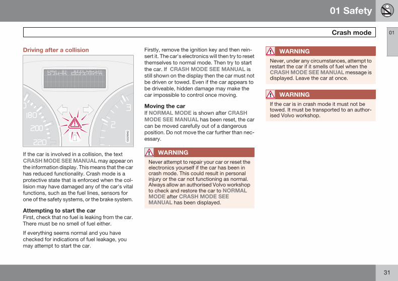
Driving after a collision
G02
9042
If the car is involved in a collision, the textCRASH MODE SEE MANUAL may appear onthe information display. This means that the carhas reduced functionality. Crash mode is aprotective state that is enforced when the col-lision may have damaged any of the car's vitalfunctions, such as the fuel lines, sensors forone of the safety systems, or the brake system.
Attempting to start the carFirst, check that no fuel is leaking from the car.There must be no smell of fuel either.
If everything seems normal and you havechecked for indications of fuel leakage, youmay attempt to start the car.
Firstly, remove the ignition key and then rein-sert it. The car's electronics will then try to resetthemselves to normal mode. Then try to startthe car. If CRASH MODE SEE MANUAL isstill shown on the display then the car must notbe driven or towed. Even if the car appears tobe driveable, hidden damage may make thecar impossible to control once moving.
Moving the carIf NORMAL MODE is shown after CRASHMODE SEE MANUAL has been reset, the carcan be moved carefully out of a dangerousposition. Do not move the car further than nec-essary.
WARNING
Never attempt to repair your car or reset theelectronics yourself if the car has been incrash mode. This could result in personalinjury or the car not functioning as normal.Always allow an authorised Volvo workshopto check and restore the car to NORMALMODE after CRASH MODE SEEMANUAL has been displayed.
WARNING
Never, under any circumstances, attempt torestart the car if it smells of fuel when theCRASH MODE SEE MANUAL message isdisplayed. Leave the car at once.
WARNING
If the car is in crash mode it must not betowed. It must be transported to an author-ised Volvo workshop.
C30; 7; 3 2008-03-04T12:19:30+01:00; Page 31evastarck

01 Safety
Child safety01
32
Children should sit comfortably andsafelyThe position of a child in the car and the choiceof equipment are dictated by the child's weightand size. For more information, seepage 33.
NOTE
Regulations regarding the placement ofchildren in cars vary from country to coun-try. Check what does apply.
Children of all ages and sizes must always sitcorrectly secured in the car. Never allow a childto sit on the knee of a passenger.
Volvo's own child safety equipment isdesigned for your car. Use Volvo genuineequipment to best ensure that the mountingpoints and attachments are correctly posi-tioned and are sufficiently strong.
NOTE
In the event of questions when fitting childsafety products, contact the manufacturerfor clearer instructions.
Child seats
G02
0128
Child seats and airbags are not compatible.
Volvo has child safety products that aredesigned for and tested by Volvo.
NOTE
When using child safety products it isimportant to read the installation instruc-tions included with the product.
Do not attach the straps for the child seat tothe horizontal adjustment bar, springs, rails or
beams under the seat. Sharp edges can dam-age the straps.
Allow the back of the child seat to rest againstthe dashboard. This applies to cars without apassenger airbag, or where the airbag is deac-tivated.
Location of child seatsYou may place:
• a child seat/booster cushion on the frontpassenger seat, provided the passengerairbag is not activated 1.
• a rear-facing child seat in the rear seat thatuses the back of the front seat as support.
Always place a child in the rear seat if the pas-senger airbag is activated. A child in the frontpassenger seat could suffer serious injury if theairbag deploys.
1 For information on activated/deactivated airbag (SRS), see page 23.
C30; 7; 3 2008-03-04T12:19:30+01:00; Page 32evastarck

01 Safety
Child safety 01
33
WARNING
Never place a child in a child seat or on abooster cushion in the front seat if the airbag(SRS) is activated.
No one shorter than 140 cm should ever sitin the front passenger seat if the airbag(SRS) is activated.
Failure to follow the advice given above canendanger the life of the child.
WARNING
Booster cushions/child seats with steelbraces or some other design that could reston the seatbelt buckle's opening buttonmust not be used, as they could cause theseatbelt buckle to open accidentally.
Do not allow the upper section of the childseat to rest against the windscreen.
Label Airbag
Label located on instrument panel end face.
Placement of children in the car 3
Weight/age Front seat A Rear seat
Group 0
max. 10 kg
(0 – 9 months)
Group 0+
max. 13 kg
Volvo Child seat – rear-facing child seat, secured withthe car's seatbelt and straps. Use a protective cushionbetween the child seat and the dashboard.
Type approval: E5 03135
Volvo Child seat – rear-facing child seat, secured with thecar's seatbelt, straps and support legs. B
Type approval: E5 03135
Britax Baby Safe Plus – rear-facing child seat, securedwith the ISOFIX fixture system.
Type approval: E1 03301146
Britax Baby Safe Plus – rear-facing child seat, secured withthe ISOFIX fixture system.
Type approval: E1 03301146
2 For information on activated/deactivated airbag (SRS) see page 23.3 With regard to other child seats the car should be included in the manufacturer's enclosed list of vehicles or be universally approved in accordance with the ECE R44 legal requirement.
C30; 7; 3 2008-03-04T12:19:30+01:00; Page 33evastarck
2

01 Safety
Child safety01
34
Weight/age Front seat A Rear seat
Group 1
9 – 18 kg
(9 – 36 months)
Volvo Child seat – rear-facing child seat, secured withthe car's seatbelt and straps. Use a protective cushionbetween the child seat and the dashboard.
Type approval: E5 03135
Volvo Child seat – rear-facing child seat, secured with thecar's seatbelt, straps and support legs.
Type approval: E5 03135
Britax Fixway – rear-facing child seat, secured with theISOFIX fixture system and straps.
Type approval: E5 03171
Britax Fixway – rear-facing child seat, secured with theISOFIX fixture system and straps.
Type approval: E5 03171
Group 2/3
15 – 36 kg
(3 – 12 years)
Volvo Booster cushion – with or without backrest.
Type approval: E5 03139
Volvo Booster cushion – with or without backrest.
Type approval: E5 03139
A For information on activated/deactivated airbag (SRS), see page 23.B To install a rear-facing child seat in the rear seat, contact an authorised Volvo dealer to have the mounting points installed.
WARNING
Never place a child in a child seat or on abooster cushion in the front seat if the airbag(SRS) is activated.
No one shorter than 140 cm should ever sitin the front passenger seat if the airbag(SRS) is activated.
Failure to follow the advice given above canendanger the life of the child.
4 For information on activated/deactivated airbag (SRS) see page 23.
C30; 7; 3 2008-03-04T12:19:30+01:00; Page 34evastarck
B
B
4

01 Safety
Child safety 01
* Option/accessory, for more information, see Introduction. 35
ISOFIX fixture system for child seats*
G00
9182
Mounting points for the ISOFIX fixture systemare concealed behind the lower section of therear seat backrest, in the outer seats.
The location of the mounting points is indicatedby symbols in the backrest upholstery (seeillustration above).
Press the seat cushion down to access themounting points.
Always follow the manufacturer's installationinstructions when connecting a child seat tothe ISOFIX mounting points.
Mounting points for child seats
G02
6316
The car is equipped with upper mountingpoints for child seats. These mounting pointsare located on the rear side of the rear seat.
The child seat's straps must be routedbetween the head restraint and the backrest.
For detailed information on how to secure thechild seat in the upper mounting points, referto the instructions from the child seat manu-facturer
C30; 7; 3 2008-03-04T12:19:30+01:00; Page 35evastarck

G02
0901
36 * Option/accessory, for more information, see Introduction.
Overview, left-hand drive cars................................................................ 38Overview, right-hand drive cars.............................................................. 40Driver's door control panel...................................................................... 42Combined instrument panel.................................................................... 43Indicator and warning symbols............................................................... 44Information display.................................................................................. 48Electrical socket...................................................................................... 50Lighting panel.......................................................................................... 51Left-hand stalk switch............................................................................. 53Right-hand stalk switch.......................................................................... 56Cruise control*........................................................................................ 59Keypad in the steering wheel*................................................................. 61Steering wheel adjustment, hazard warning flashers............................. 62Parking brake.......................................................................................... 63Power windows....................................................................................... 64Rearview and door mirrors...................................................................... 66Power sunroof*........................................................................................ 70Personal preferences.............................................................................. 71
HomeLink EU*....................................................................................... 74
C30; 7; 3 2008-03-04T12:19:30+01:00; Page 36evastarck

02INSTRUMENTS AND CONTROLS
C30; 7; 3 2008-03-04T12:19:30+01:00; Page 37evastarck

02 Instruments and controls
Overview, left-hand drive cars
02
38
G01
9492
C30; 7; 3 2008-03-04T12:19:30+01:00; Page 38evastarck

02 Instruments and controls
Overview, left-hand drive cars
02
39
Steering wheel adjustment
Bonnet release
Control panel
Direction indicators, main beam, trip com-puter
Lighting, fuel filler flap opener
Air vents in dashboard
Air vent for side window
Cruise control
Horn, airbag
Combined instrument panel
Keypad for infotainment system
Windscreen wipers and washer, headlampwashers
Ignition switch
Sunroof controls
No function
No function
Switch for interior lighting
Reading lamp, left-hand side
Reading lamp, right-hand side
Seatbelt reminder and passenger seat air-bag indicator
Interior rearview mirror
Display for climate control and infotain-ment system
Infotainment system
Controls for climate control, infotainmentsystem and personal preferences
Climate control
Gear lever
Hazard warning flashers
Door handle
Glovebox
Parking brake
Electrical socket/cigarette lighter
Blind Spot Information System, BLIS
Switch, optional equipment
C30; 7; 3 2008-03-04T12:19:30+01:00; Page 39evastarck
Door handle, lock button

02 Instruments and controls
Overview, right-hand drive cars
02
40
29 9 23 26 2827252491413121110
7
3
4
2
1
6
9
8
5
8
18
15
21
22
20
17
19
16
34
33
5
32
31
30
9
G01
9493
C30; 7; 3 2008-03-04T12:19:30+01:00; Page 40evastarck

02 Instruments and controls
Overview, right-hand drive cars
02
41
Electrical socket, cigarette lighter
Blind Spot Information System, BLIS
Switch, optional equipment
Parking brake
Control panel
Glovebox
Door handle
Air vent for side window
Air vents in dashboard
Gear lever
Climate control
Controls for climate control, infotainmentsystem and personal preferences
Infotainment system
Display for climate control and infotain-ment system
Interior rearview mirror
Seatbelt reminder and passenger seat air-bag indicator
Switch for interior lighting
Reading lamp, left-hand side
Reading lamp, right-hand side
No function
No function
Sunroof controls
Ignition switch
Windscreen wipers and washers, head-lamp washers
Cruise control
Combined instrument panel
Horn, airbag
Keypad for infotainment system
Hazard warning flashers
Door handle, lock button
Lighting, fuel filler flap opener
Direction indicators, main beam, trip com-puter
Bonnet release
Steering wheel adjustment
C30; 7; 3 2008-03-04T12:19:30+01:00; Page 41evastarck

02 Instruments and controls
Driver's door control panel
02
42
Driver's door control panel
G01
7449
Power windows
Door mirror, left-hand side
Door mirrors, setting
Door mirror, right-hand side
C30; 7; 3 2008-03-04T12:19:30+01:00; Page 42evastarck

02 Instruments and controls
Combined instrument panel
02
43
G02
9046
Speedometer.
Direction indicators, left.
Warning symbol.
Information display – The display presentsinformation or warning messages, outsidetemperature and clock. When the outsidetemperature is between +2 °C and -5 °C asnowflake symbol appears on the display.This warns of icy roads. The outside tem-perature gauge may show a slightly highreading after the car has been stationary.
Information symbol.
Direction indicator, right.
Tachometer – Indicates engine speed inthousands of revolutions per minute (rpm).
Indicator and warning symbols.
Main beam indicator.
Display – Display for automatic gear posi-tion, rain sensor, odometer, trip meter andcruise control.
Button for trip meter – Used to measureshort distances. Short presses on the but-ton switches between the two trip metersT1 and T2. A long press (more than 2 sec-onds) resets an active trip meter to zero.
Temperature gauge - Used for the enginecooling system. A message will appear onthe display if the temperature becomes toohigh and the gauge goes into the red zone.Bear in mind that extra lights placed in frontof the air intake, for example, reduce thecooling capacity at high outside tempera-tures and high engine loads.
Indicator and warning symbols.
C30; 7; 3 2008-03-04T12:19:30+01:00; Page 43evastarck
page 54.Fuel gauge, see also trip computer,

02 Instruments and controls
Indicator and warning symbols
02
44
Functionality check, symbolsAll indicator and warning symbols 1 illuminatewhen the ignition key is turned to position IIbefore starting. This is to check that the sym-bols are working. When the engine starts, allthe symbols should go out except the hand-brake symbol, which only goes out when thebrake is disengaged.
If the engine does not start withinfive seconds, all symbols extin-guish except the symbols for afault in the car's emissions systemand for low oil pressure. Certainsymbols may have no function,depending on the car's specifica-tions.
Symbols in the centre of the instrumentpanel
G03
0755
The red warning symbol illumi-nates when a fault has been indi-cated which could affect the safetyand/or driveability of the car. Anexplanatory text is shown on the
information display at the same time. The sym-bol remains visible until the fault has been rec-tified but the text message can be cleared withthe READ button, see page 48. The warningsymbol can also illuminate in conjunction withother symbols.
When the symbol illuminates:
1. Stop in a safe manner. Do not drive the carfurther.
2. Read the information on the informationdisplay. Implement the action in accord-ance with the message in the display. Clearthe message using READ.
The yellow information symbol illu-minates and a text appears on theinformation display. The messagetext is cleared using the READ but-ton, see page 48, or disappears
automatically after a period of time (timedepending on which function is indicated).
The yellow information symbol can also illumi-nate in conjunction with other symbols.
NOTE
When a service message is shown, the sym-bol and message are cleared using theREAD button, or disappear automaticallyafter a time.
1 For certain engine variants, the symbol for low oil pressure is not used. Warnings are given via display text, see page 48.
C30; 7; 3 2008-03-04T12:19:30+01:00; Page 44evastarck

02 Instruments and controls
Indicator and warning symbols
02
* Option/accessory, for more information, see Introduction. 45
Indicator symbols – left-hand side
G02
9048
Fault in car's emissions system
ABS fault
Rear fog lamp
Stability system STC or DSTC
No function
Engine preheater (diesel)
Low level in fuel tank
Emissions systemIf the symbol illuminates then itmay be due to a fault in the car'semissions system. Drive to anauthorised Volvo workshop tohave the system checked.
ABS faultIf this symbol illuminates then thesystem is not working. The car'sregular brake system continues towork, but without the ABS func-tion.
1. Stop the car in a safe place and turn off theengine.
2. Restart the engine.
3. Drive to an authorised Volvo workshop tohave the ABS checked if the symbolremains lit.
Rear fog lampThis symbol is lit when the rear foglamp is on.
Stability system STC or DSTC*For information on the system'sfunctions and symbols, seepage 144.
Engine preheater (diesel)This symbol illuminates duringengine preheating. Preheatingoccurs when the temperature isbelow –2 °C. The car can bestarted once the symbol goes out.
Low level in fuel tankWhen the symbol illuminates thelevel in the fuel tank is low, refuelas soon as possible.
C30; 7; 3 2008-03-04T12:19:30+01:00; Page 45evastarck

02 Instruments and controls
Indicator and warning symbols
02
46
Indicator symbols – right-hand side
G02
9049
Indicator symbol for trailer
Parking brake applied
Airbags – SRS
Low oil pressure
Seatbelt reminder
Alternator not charging
Fault in brake system
Indicator symbol for trailerThis symbol flashes when thedirection indicators are used andthe trailer is connected. If the sym-bol does not flash then one of thelamps on the trailer or the car is
faulty.
Parking brake appliedThe symbol illuminates when theparking brake is applied. Alwayspull the parking brake lever to theend position.
NOTE
The symbol illuminates irrespective of howhard the parking brake is applied.
Airbags – SRSIf this symbol remains illuminatedor illuminates while driving, itmeans a fault has been detected inthe seatbelt buckle, SRS, SIPS, orIC system. Drive directly to an
authorised Volvo workshop to have the systemchecked.
Low oil pressure 2
If this symbol illuminates duringdriving then the engine's oil pres-sure is too low. Stop the engineimmediately and check the engineoil level, top up if necessary. If the
symbol illuminates and the oil level is normal,contact an authorised Volvo workshop.
Seatbelt reminderThis symbol illuminates if someonein a front seat has not put on theirseatbelt or if someone in a rearseat has taken off their seatbelt.
Alternator not chargingIf this symbol illuminates whiledriving, a fault has occurred in theelectrical system. Contact anauthorised Volvo workshop.
Fault in brake systemIf this symbol illuminates, the brakefluid level may be too low.
Stop the car in a safe place and check thelevel in the brake fluid reservoir, seepage 200. If the level in the reservoir is
2 For certain engine variants, the symbol for low oil pressure is not used. Warnings are given via display text, see page 48.
C30; 7; 3 2008-03-04T12:19:30+01:00; Page 46evastarck

02 Instruments and controls
Indicator and warning symbols
02
47
below MIN the car should not be driven anyfurther. Have the car transported to anauthorised Volvo workshop to have thebrake system checked.
If the BRAKE and ABS symbolsilluminate at the same time, theremay be a fault in the brake forcedistribution system.
1. Stop the car in a safe place and turn off theengine.
2. Restart the engine.
3. If both symbols extinguish, continue driv-ing.
4. If the symbols remain illuminated, checkthe level in the brake fluid reservoir, seepage 200.
5. If the brake fluid level is normal but thesymbols are still lit, the car can be driven,with great care, to an authorised Volvoworkshop to have the brake systemchecked.
6. If the level in the reservoir is below MINthen the car should not be driven any fur-ther. Have the car transported to anauthorised Volvo workshop to have thebrake system checked.
WARNING
If the BRAKE and ABS symbols are lit at thesame time, there is a risk that the rear endwill skid during heavy braking.
Reminder – doors not closedIf one of the doors, the bonnet 3 or the tailgateis not properly closed, the driver will bereminded of this.
Low speedIf the car moves at a speed lessthan 5 km/h, the information sym-bol illuminates and DRIVERDOOR OPEN, PASSENGERDOOR OPEN or BONNET OPEN
is shown on the display. Stop the car safely assoon as possible and close the door or bonnet.
High speedIf the car is moving faster than10 km/h, the symbol illuminatesand one of the texts indicated inthe preceding paragraph appearson the display.
Tailgate reminderIf the tailgate is open, this informa-tion symbol will illuminate andTAILGATE OPEN will appear onthe display.
3 Only cars with alarm.
C30; 7; 3 2008-03-04T12:19:30+01:00; Page 47evastarck

02 Instruments and controls
Information display
02
48
Messages
G02
9050
When a warning or indicator symbol illuminatesthe information display shows a supplemen-tary message.
Press the READ button (1).
Switch between messages with the READ but-ton. Fault messages are stored in the memoryuntil the fault is rectified.
NOTE
If a warning message appears while you areusing the trip computer, the message mustbe read (press READ) before the previousactivity can be resumed.
Message Specification
STOP SAFELYA Stop the car in a safemanner and turn offthe engine. Seriousrisk of damage.
SERVICEURGENTA
Have the carchecked by anauthorised Volvoworkshop immedi-ately.
SEE MANUALA Read the Owner'sManual.
SERVICEREQUIREDA
Have the carchecked by anauthorised Volvoworkshop as soonas possible.
HIGH ENGINETEMP STOPENGINE
Stop the car in a safemanner and turn offthe engine. Seriousrisk of damage.
BOOK TIME FORSERVICE
Time to book regularservice at an author-ised Volvo work-shop.
Message Specification
TIME FOR SERV-ICE
Time for regularservice at an author-ised Volvo work-shop. The timing isdetermined by thenumber of kilome-tres driven, numberof months since thelast service, enginerunning time and oilgrade.
MAINTENANCEOVERDUE
If the service inter-vals are not followedthen the warrantydoes not cover anydamaged parts.Contact an author-ised Volvo work-shop for service.
TRANSMISSIONOIL CHANGE NEE-DED
Have the carchecked by anauthorised Volvoworkshop as soonas possible.
C30; 7; 3 2008-03-04T12:19:30+01:00; Page 48evastarck

02 Instruments and controls
Information display
02
49
Message Specification
REMINDERCHECK OIL LEVEL
Check the oil level.The message isshown every10 000 km (certainengine variants). Forinformation onchecking the oillevel, see page 198.
SOOT FILTERFULL SEE MAN-UAL
Diesel particle filterrequires regenera-tion, see page 270.
STC/DSTC SPINCONTROL OFF
The function of thestability and tractioncontrol system isreduced, seepage 145 for morevariants.
TRANSMISSIONPERFORMANCELOW
The gearbox cannothandle full capacity.Drive carefully untilthe message clears,see page 140.
If shown repeatedly:Contact an author-ised Volvo work-shop.
Message Specification
TRANSMISSIONOIL TEMP HIGH
Drive more smoothlyor stop the car in asafe manner. Disen-gage the gear andrun the engine atidling speed until themessage clears. Formore information,see page 140.
TRANSMISSIONHOT STOPSAFELY
Critical fault. Stopthe car immediatelyin a safe manner.Contact an author-ised Volvo work-shop. B
A Part of message, shown together with information on wherethe problem has arisen.
B For more messages concerning automatic transmission, seepage 140.
C30; 7; 3 2008-03-04T12:19:30+01:00; Page 49evastarck

02 Instruments and controls
Electrical socket
02
50 * Option/accessory, for more information, see Introduction.
12 V electrical socket
G01
9621
The electrical socket can be used for 12 Vaccessories, such as mobile phone chargersand coolers. The maximum current is 10 A. Forthe socket to supply current, the ignition keymust be in at least position I.
WARNING
Always leave the plug in the socket whenthe socket is not in use.
Cigarette lighter*Activate the lighter by pushing in the button.The button pops out when the lighter is hot. Pullout the lighter and light a cigarette on theheated coils.
Electrical socket in the rear seat
G02
9082
The electrical socket can be used for variousaccessories, such as mobile phone chargersand coolers.
NOTE
Cigarette lighter does not work in thissocket.
It is designed for 12 V. The maximum currentis 10 A. For the socket to supply current, theignition key must be in at least position I.
WARNING
Always leave the plug in the socket when itis not in use.
C30; 7; 3 2008-03-04T12:19:30+01:00; Page 50evastarck

02 Instruments and controls
Lighting panel
02
* Option/accessory, for more information, see Introduction. 51
General
G02
0139
Thumbwheel for headlamp levelling
Light switches
Thumbwheel for adjusting display andinstrument lighting
Front fog lamps*
Opening the fuel filler flap
Rear fog lamp
Posi-tion
Specification
Automatic/deactivated dippedbeam. Only main beam flash.
Position/parking lamps.
Automatic dipped beam. Mainbeam and main beam flashwork in this position.
Headlamp levellingThe load in the car changes the vertical align-ment of the headlamp beam, which could daz-zle oncoming motorists. Avoid this by adjustingthe height of the beam.
1. Turn the ignition key to position II.
2. Turn the headlamp control (2) to one of theend positions.
3. Roll the control (1) up or down respectivelyto raise or lower beam alignment.
Cars with Bi-Xenonmatic headlamp levelling, so there is no control(1).
Position/parking lamps can be switched onirrespective of ignition key position.
Turn the headlamp control (2) to the centreposition.
When the ignition key is in position II the posi-tion/parking lamps and number plate lightingare always on.
Headlamps
Automatic dipped beam*Dipped beam comes on automatically whenthe ignition key is turned to position II, exceptwhen the headlamp control (2) is in the centreposition. If necessary, the automatic dippedbeam can be deactivated by an authorisedVolvo workshop.
Automatic dipped beam, main beam1. Turn the ignition key to position II.
2. Dipped beam is activated by means ofturning the headlamp control (2) clockwiseto the end position.
3. Main beam is activated by means of mov-ing the left-hand stalk switch towards thesteering wheel to the end position andreleasing it, see page 53.
The lamps are switched off automatically whenthe ignition key is turned to position I or 0.
C30; 7; 3 2008-03-04T12:19:30+01:00; Page 51evastarck
Position/parking lamps
headlamps* have auto-

02 Instruments and controls
Lighting panel
02
52 * Option/accessory, for more information, see Introduction.
Instrument lightingThe instrument lighting is switched on whenthe ignition key is in position II and the head-lamp control (2) is in one of the end positions.The lighting is automatically dimmed during theday and can be controlled manually at night.
Roll the control up or down (3) for brighteror dimmer lighting.
Enhanced display lightingTo facilitate reading the odometer, trip meter,clock and outside temperature gauge, theseilluminate when the car is unlocked and whenthe key is removed from the ignition switch.The displays extinguish when the car is locked.
Fog lamps
NOTE
Regulations for use of fog lamps vary fromcountry to country.
Front fog lamps*The front fog lamps can be switched on alongwith the headlamps or the position lamps/park-ing lamps.
Press the button (4).
The light in the button (4) illuminates when thefront fog lamps are switched on.
Rear fog lampThe rear fog lamp can only be switched on withthe headlamps or the front fog lamps.
Press the button (6).
The rear fog lamp indicator symbol on the com-bined instrument panel and the light in thebutton (6) illuminate when the rear fog lamp isswitched on.
Fuel filler flapPress button (5) to open the fuel filler flap whenthe car is unlocked, see page 120.
Brake lightThe brake light automatically comes on duringbraking.
Emergency brake light and automatichazard warning flashers, EBL*Emergency Brake Lights (EBL) are activated inthe event of heavy braking or if the ABS brakesare activated. This function means that thebrake light flashes to immediately alert carstravelling behind.
The system is activated if ABS is used for morethan 0.5 seconds or in the event of heavy brak-ing, however, only when braking from speeds
above 50 km/h. When the speed of the car islower than 30 km/h the brake lights shine nor-mally again and the hazard warning flashersare switched on automatically. The hazardwarning flashers remain on until the car accel-erates again but can be deactivated with thebutton for hazard warning flashers, seepage 62.
C30; 7; 3 2008-03-04T12:19:30+01:00; Page 52evastarck

02 Instruments and controls
Left-hand stalk switch
02
53
Stalk switch positions
34
1
2
1
2
G02
6380
Short flash sequence, direction indicators
Continuous flash sequence, direction indi-cators
Main beam flash and switching from mainto dipped beam
Home safe lighting and switching fromdipped to main beam
Direction indicators
Continuous flash sequenceMove the stalk switch up or down to endposition (2).
The stalk switch remains in its end position andis moved back manually, or automatically bysteering wheel movement.
Short flash sequenceMove the stalk switch up or down to posi-tion (1) and release.
The direction indicators flash three times andthe stalk switch returns to its home position.
Main beam flashMove the stalk switch gently towards thesteering wheel to position (3).
Main beam comes on until the stalk switch isreleased. Main beam flash only works when theignition key is inserted in the ignition switch.
Switching, main and dipped beamThe ignition key must be in position II and theheadlamp control in end position, seepage 51, for main beam to be switched on.
Activating main beam:
Move the stalk switch towards the steeringwheel to the end position (4) and release.
Deactivating main beam:
Move the stalk switch towards the steeringwheel to position (3) and release.
Home safe lightingSome of the exterior lighting can be keptswitched on to work as home safe lighting afterthe car has been locked. The standard delay is30 1 seconds, but can be changed to 60 or 90seconds, see page 72.
1. Remove the key from the ignition switch.
2. Move the stalk switch towards the steeringwheel to the end position (4) and release.
3. Get out of the car and lock the door.
1 Factory settings.
C30; 7; 3 2008-03-04T12:19:30+01:00; Page 53evastarck

02 Instruments and controls
Left-hand stalk switch
02
54 * Option/accessory, for more information, see Introduction.
Trip computer*
G02
9052
READ - confirms
Thumbwheel 2 - browse between menusand options in the trip computer list
ControlsTo scroll through trip computer informationturn the thumbwheel either up or down insteps. Continue turning to return to the startingpoint.
NOTE
If a warning message interrupts while youare using the trip computer, this messagemust be acknowledged. Acknowledge bypressing the READ button and revert to thetrip computer function.
FunctionsThe trip computer displays the following infor-mation:
• AVERAGE SPEED
• ACTUAL SPEED MPH*
• INSTANTANEOUS
• AVERAGE
• KILOMETRES TO EMPTY TANK
• STC/DSTC, see page 144
AVERAGE SPEEDWhen the ignition is switched off, the averagespeed is stored and used as the basis of thenew value when you continue driving. Resetusing the RESET button.
ACTUAL SPEED MPHCurrent speed is displayed in mph.
INSTANTANEOUSCurrent fuel consumption is calculated everysecond. The information on the display is
updated every couple of seconds. When thecar is stationary, " --.-" appears on the display.During the period for regeneration 3 fuel con-sumption may increase, see page 270.
AVERAGEThe average fuel consumption is stored whenthe ignition is switched off and remains until thefunction is reset. Reset using the RESET but-ton.
NOTE
There may be a slight error in the reading ifa fuel-driven heater is used.
KILOMETRES TO EMPTY TANKThe range to empty is calculated based on theaverage fuel consumption over the last 30 km.No guaranteed range remains when the displayshows " --- km to empty tank". Refuel assoon as possible.
NOTE
There may be a slight error in the reading iffuel consumption is changed due to achange in driving style or if a fuel-drivenheater is used for example.
2 No function in cars without trip computer, fuel-driven parking heater as well as stability and traction control system.3 Only applies to diesel cars with particle filter.
C30; 7; 3 2008-03-04T12:19:30+01:00; Page 54evastarck
2RESET - resets

02 Instruments and controls
Left-hand stalk switch
02
55
Resetting1. Select AVERAGE SPEED or AVERAGE
2. Reset with one press on the RESET but-ton. Press and hold the RESET button forat least five seconds to reset the averagespeed and average consumption at thesame time.
C30; 7; 3 2008-03-04T12:19:30+01:00; Page 55evastarck

02 Instruments and controls
Right-hand stalk switch
02
56 * Option/accessory, for more information, see Introduction.
Windscreen wipers
0
0
A
C DB
G02
5411
Windscreen and headlamp washers
Rain sensor - On/Off
Thumbwheel
Rear window wiper and washer
Windscreen wipers offThe windscreen wipers are offwhen the stalk switch is in position0.
Single sweepRaise the stalk switch to make asingle sweep.
Intermittent wipingYou can adjust and set a suitablespeed for intermittent wiping. Turnthe thumbwheel (C) up for a shorterinterval between sweeps. Turn itdown to increase the delay.
Continuous wipingThe wipers sweep at normalspeed.
The wipers sweep at high speed.
IMPORTANT
Before activating the wipers during winter –ensure that the wiper blades are not frozenin and that any snow or ice on the wind-screen (and rear window) is scraped away.
IMPORTANT
Use plenty of washer fluid when the wipersare cleaning the windscreen. The wind-screen must be wet when the windscreenwipers are operating.
Windscreen/headlamp washerMove the stalk switch toward the steeringwheel to start the windscreen and headlampwashers. The wipers will make several moresweeps once the stalk switch is released.
High-pressure headlamp washing*High-pressure headlamp washing consumes alarge quantity of washer fluid. To save fluid, theheadlamps are washed as follows:
Dipped beam selected with the switch on light-ing panel:
The headlamps are washed the first time thewindscreen is washed. Within the next tenminutes, they are washed every fifth washcycle of the windscreen. In the event of a longerinterval the headlamps are washed each time.
Parking/position lamps selected with theswitch on the lighting panel:
• Bi-Xenon headlamps are only washedevery fifth wash cycle irrespective of thetime that elapses.
• Halogen headlamps are not washed.
The switch on the lighting panel is in position0:
• Bi-Xenon headlamps are only washedevery fifth wash cycle irrespective of thetime that elapses.
• Halogen headlamps are not washed.
C30; 7; 3 2008-03-04T12:19:30+01:00; Page 56evastarck
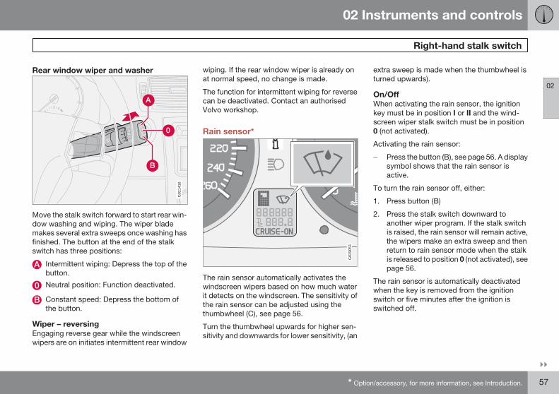
02 Instruments and controls
Right-hand stalk switch
02
* Option/accessory, for more information, see Introduction. 57
Rear window wiper and washer
0
G02
1418
Move the stalk switch forward to start rear win-dow washing and wiping. The wiper blademakes several extra sweeps once washing hasfinished. The button at the end of the stalkswitch has three positions:
Intermittent wiping: Depress the top of thebutton.
Neutral position: Function deactivated.
Constant speed: Depress the bottom ofthe button.
Wiper – reversingEngaging reverse gear while the windscreenwipers are on initiates intermittent rear window
wiping. If the rear window wiper is already onat normal speed, no change is made.
The function for intermittent wiping for reversecan be deactivated. Contact an authorisedVolvo workshop.
Rain sensor*
G02
9053
The rain sensor automatically activates thewindscreen wipers based on how much waterit detects on the windscreen. The sensitivity ofthe rain sensor can be adjusted using thethumbwheel (C), see page 56.
Turn the thumbwheel upwards for higher sen-sitivity and downwards for lower sensitivity, (an
extra sweep is made when the thumbwheel isturned upwards).
On/OffWhen activating the rain sensor, the ignitionkey must be in position I or II and the wind-screen wiper stalk switch must be in position0 (not activated).
Activating the rain sensor:
Press the button (B), see page 56. A displaysymbol shows that the rain sensor isactive.
To turn the rain sensor off, either:
1. Press button (B)
2. Press the stalk switch downward toanother wiper program. If the stalk switchis raised, the rain sensor will remain active,the wipers make an extra sweep and thenreturn to rain sensor mode when the stalkis released to position 0 (not activated), seepage 56.
The rain sensor is automatically deactivatedwhen the key is removed from the ignitionswitch or five minutes after the ignition isswitched off.
C30; 7; 3 2008-03-04T12:19:30+01:00; Page 57evastarck

02 Instruments and controls
Right-hand stalk switch
02
58
IMPORTANT
At an automatic car wash: Deactivate therain sensor by pressing the button (B) whilethe ignition key is in position I or II. Other-wise, the windscreen wipers could startswiping and become damaged.
ThumbwheelUse the thumbwheel to adjust the frequency ofwiper sweeps when intermittent wiping isselected, or the sensitivity to rain when the rainsensor is selected.
C30; 7; 3 2008-03-04T12:19:30+01:00; Page 58evastarck

02 Instruments and controls
Cruise control*
02
* Option/accessory, for more information, see Introduction. 59
Activating
G02
0141
The controls for cruise control are to the left ofthe steering wheel.
Setting the desired speed:
1. Press the CRUISE button. CRUISE isshown on the combined instrument panel.
2. Touch + or – to lock the vehicle speed.
instrument panel.
Cruise control cannot be engaged at speedsbelow 30 km/h or above 200 km/h.
Increasing or decreasing speed
G02
9054
Increase or decrease the speed by press-ing and holding + or –. The speed of the carwhen the button is released is set as thenew speed.
A brief press (less than half a second) on + or– changes the speed by 1 km/h or 1 mph 1.
NOTE
A temporary increase in speed (less thanone minute) using the accelerator, such aswhile overtaking, does not affect the cruisecontrol setting. When you release the accel-erator, the car will return to the programmedspeed.
Temporary disengagementPress 0 to disengage the cruise controltemporarily. CRUISE will be shown on thecombined instrument panel. The speed setearlier is stored in the memory.
The cruise control is also temporarily disen-gaged when:
• the brake pedal or clutch pedal isdepressed
•elling uphill
• the gear selector is moved to position N
•• a temporary increase in speed lasts longer
than one minute.
1 Depending on engine type.
C30; 7; 3 2008-03-04T12:19:30+01:00; Page 59evastarck
CRUISE ON appears in the combined
1speed falls below 25–30 km/h when trav-
wheel spin or wheel lock-up occurs

02 Instruments and controls
Cruise control*
02
60 * Option/accessory, for more information, see Introduction.
Return to the set speed– Press this button to resume thepreviously set speed. CRUISEON appears on the combinedinstrument panel.
DisengagingPress CRUISE to disengage the cruisecontrol. CRUISE ON clears on the com-bined instrument panel.
C30; 7; 3 2008-03-04T12:19:30+01:00; Page 60evastarck

02 Instruments and controls
Keypad in the steering wheel*
02
* Option/accessory, for more information, see Introduction. 61
Button functions
G02
0142
The four buttons at the bottom of the steeringwheel keypad control the radio and the phone.The function of a button depends on whichsystem is active. The steering wheel keypadcan be used to scroll between preset stations,change CD tracks and adjust the volume.
Press and hold one of the arrow keys tofast forward/reverse or search for the nextstation.
The phone must be switched on to adjust audiosystem settings. It must be activated with theENTERkey to enable control of the phone sys-tem with the arrow keys.
To return to Audio only, press EXIT.
C30; 7; 3 2008-03-04T12:19:30+01:00; Page 61evastarck

02 Instruments and controls
Steering wheel adjustment, hazard warning flashers
02
62
Steering wheel adjustment
G02
0143
The steering wheel can be adjusted for bothheight and reach.
1. Pull the lever towards you to release thesteering wheel.
2. Adjust the steering wheel to the positionthat suits you best.
3. Push back the lever to fix the steeringwheel in place. If the lever is stiff, press thesteering wheel lightly at the same time asyou push the lever back.
WARNING
Adjust the steering wheel before driving off,never while driving. Before driving, checkthat the steering wheel is fixed in position.
Hazard warning flashers
G02
0144
Use the hazard warning flashers (all directionindicators flash) when the car is stopped whereit could be a traffic hazard or obstruction. Pressthe button to activate the function.
A sufficiently violent collision or heavy brakingactivates the hazard warning flashers automat-ically, see page 52. The function can be deac-tivated with the button.
NOTE
Regulations regarding the use of hazardwarning flashers vary from country to coun-try.
C30; 7; 3 2008-03-04T12:19:30+01:00; Page 62evastarck

02 Instruments and controls
Parking brake
02
63
Parking brake (handbrake)
G01
8260
The lever is located between the front seats.
NOTE
The warning lamp symbol in the combinedinstrument panel illuminates irrespective ofhow hard the parking brake is applied.
1. Press the foot brake pedal down firmly.
2. Pull up the parking brake lever up firmly toits full extent.
3. Release the foot brake pedal and makesure that the car is at a standstill position.
4. If the vehicle rolls, the parking brake levermust be pulled more firmly.
When parking a vehicle always put the gearselector in position 1 (for manual transmission)
Parking on a hillIf the car is parked facing uphill; turn the wheelsaway from the kerb.
If the car is parked facing downhill; turn thewheels toward the kerb.
How to release the parking brake1. Press the foot brake pedal down firmly.
2. Pull the parking brake lever up slightly,press the button, release the parking brakelever and release the button.
C30; 7; 3 2008-03-04T12:19:30+01:00; Page 63evastarck
or P (for automatic transmission).
How to apply the parking brake

02 Instruments and controls
Power windows
02
64
OperationThe power windows are operated using thecontrols in the doors. The ignition key must bein position I or II for the power windows tooperate.
The windows continue to work for a limitedamount of time when the car is stopped andignition key is removed, provided none of thedoors is opened. Operate the windows withcaution.
To open a window:
Depress the front of the control.
To close a window:
Raise the front of the control.
Remote control and lock buttonsTo operate the power windows with lock but-tons and remote control, see pages 112 and120.
WARNING
Make sure that children and other passen-gers cannot be trapped in any way whenclosing the windows. Pay close attention ifthe windows are closed with the remotecontrol.
Driver's door
G01
8240
Controls, power windows front
The driver can operate both of the power win-dows from the driver's seat.
The windows can be opened and closed in twoways:
Manual operationDepress one of the controls (A) gently or raiseit gently. The power window opens or closesas long as the switch is actuated.
Automatic operationFully depress one of the controls (A) or raise it,then release. The side window will then openor close automatically. If the window is
obstructed by an object, the movement willstop.
WARNING
The function that interrupts the movementof the windows in the event of them beingblocked works with both automatic andmanual closing, although not with pinchprotection deployed.
WARNING
If there are children in the car:
Remember to switch off the supply to thepower windows by removing the ignitionkey if the driver leaves the car.
Make sure that children and other passen-gers cannot be trapped in any way whenclosing the windows.
C30; 7; 3 2008-03-04T12:19:30+01:00; Page 64evastarck

02 Instruments and controls
Power windows
02
65
Passenger seat
G01
9511
Passenger seat.
The control in the front passenger door oper-ates that window only.
C30; 7; 3 2008-03-04T12:19:30+01:00; Page 65evastarck

02 Instruments and controls
Rearview and door mirrors
02
66 * Option/accessory, for more information, see Introduction.
Interior rearview mirror
G02
0146
Bright light from behind could be reflected inthe rearview mirror and dazzle the driver. Usedimming when disturbed by light from behind.
DippingControl for dimming
Normal position
Dimmed position.
Automatic dimming*Bright light from behind is automaticallydimmed by the rearview mirror. The control (1)is not available in mirrors with automatic dim-ming.
Interior rearview mirror with compass*
G03
1043
The upper right-hand corner of the rearviewmirror has an integrated display that shows thecompass direction in which the front of the caris pointing. Eight different directions are shownwith English abbreviations: N (north), NE (northeast), E (east), SE (south east), S (south), SW(south west), W (west) and NW (north west).
Calibrating the compass
G03
1045
The earth is divided into 15 magnetic zones.The compass is set for the geographical areato which the car was delivered. The compassshould be calibrated if the car is moved acrossseveral magnetic zones.
1. Stop the car in a wide open area with theengine running at idling speed.
2. Press and hold button (1) for at least 6 sec-onds. Following which, the character C isshown (the button is concealed so use apaper clip for example to press it in).
3. Press and hold button (1) for at least 3 sec-onds. The number for the current magneticzone is displayed.
C30; 7; 3 2008-03-04T12:19:30+01:00; Page 66evastarck

02 Instruments and controls
Rearview and door mirrors
02
67
4. Press the button (1) repeatedly until thenumber for the required magnetic zone ( 1–15) is shown, refer to the map of magneticzones for the compass.
5. Wait until the display returns to showingthe character C.
6. Following which, press and hold the buttonin for 9 seconds and select L for left-handdrive cars and R for right-hand drive.
7. Drive slowly in a circle with a maximumspeed of 10 km/h until a compass directionis shown on the display, which indicatesthat the calibration is complete.
G02
0150
Magnetic zones, Europe.
G02
0151
Magnetic zones, Asia.
G02
0152
Magnetic zones, South America.
G02
0153
Magnetic zones, Australia.
G02
0154
Magnetic zones, Africa.
C30; 7; 3 2008-03-04T12:19:30+01:00; Page 67evastarck

02 Instruments and controls
Rearview and door mirrors
02
68 * Option/accessory, for more information, see Introduction.
Door mirrors
G01
8250
The controls for adjusting the two door mirrorsare at the front of the driver's door armrest. Therearview mirrors can be operated in ignitionposition I and II.
1. Press the L button for the left-hand doormirror or the R button for the right-handdoor mirror. The light on the button illumi-nates.
2. Adjust the position with the joystick in thecentre.
3. Press the L or R button again. The lightgoes out.
Retractable power door mirrors*The mirrors can be retracted for parking/drivingin narrow spaces. This can be carried out inignition position I and II.
Retracting the mirrors1. Press the L and R button at the same time.
2. Release the buttons. The mirrors automat-ically stop in the fully retracted position.
IMPORTANT
Do not use a scraper to remove ice from themirrors as this could scratch the glass andthe water and dirt-repellent coating* couldbe damaged. Use the defroster functioninstead, see page 83 or 87.
WARNING
Both door mirrors are the wide angled typeto provide optimal vision. Objects mayappear further away than they actually are.
Folding out the mirrors1. Press the L and R button at the same time.
2. Release the buttons. The mirrors automat-ically stop in the fully extended position.
Automatic retracting/extendingWhen the car is locked/unlocked with theremote control or using the Keyless-system,
see page 116, the door mirrors are automati-cally retracted/extended.
NOTE
The door mirrors will not be extended auto-matically during unlocking if they wereretracted using the controls in the door.
If the car is locked with the remote controland is then started, the door mirrors will stillbe extended.
The function can be activated/deactivatedunder Car settings Retract mirrors whenlocking, see page 72 for a description of themenu system.
Resetting to neutralMirrors that have been moved out of positionby an external force must be reset to the neutralposition for electric retracting and extending towork.
1. Use the L and R buttons to retract the mir-rors.
2. Extend the mirrors again with the L and Rbutton. The mirrors are now reset to theneutral.
C30; 7; 3 2008-03-04T12:19:30+01:00; Page 68evastarck

02 Instruments and controls
Rearview and door mirrors
02
* Option/accessory, for more information, see Introduction. 69
Home safe and approach lightingThe light* on the door mirrors illuminates whenthe approach lighting or home safe lighting isactivated.
Blind Spot Information System, BLIS*BLIS is an information system that under cer-tain conditions can help to draw the driver'sattention to vehicles moving in the same direc-tion in the so-called "blind spot", seepage 148.
Water and dirt-repellent coating*The front side windows and/or doormirrors are treated with a coating
which improves the view in poor weather con-ditions. For information on maintenance, seepage 187.
Rearview and door mirrorsIn certain weather conditions, the function ofthe dirt-repellent coating is improved if thedoor mirror defrosters are used, seepage 83 or 86.
Heat the door mirrors:
• If they are covered with ice or snow.
• In heavy rain and dirty road conditions.
• If they are misted.
IMPORTANT
Do not use a metal ice scraper to remove icefrom the windows. The water and dirt-repel-lent coating could be damaged. Use thedefroster to remove ice from the mirrors. Anice scraper could scratch the mirror glass!
C30; 7; 3 2008-03-04T12:19:30+01:00; Page 69evastarck

02 Instruments and controls
Power sunroof*
02
70 * Option/accessory, for more information, see Introduction.
Open positions
G00
7503
The sunroof controls are located in the roofpanel. The sunroof can be opened in two posi-tions:
Ventilation position, up at the rear edge
Sliding position, backwards/forwards
The ignition key must be in position I or II.
WARNING
If there are children in the car:
Switch off the supply to the power sunroofby removing the ignition key if the driverleaves the car.
G02
9222
Opening, automatic
Opening, manual
Closing, manual
Closing, automatic
Opening, ventilation position
Closing, ventilation position
Ventilation positionOpen:
Press the rear edge of the control (5)upward.
Close:
Pull the rear edge of the control (6) down-ward.
From ventilation position to fully open sunroof:
Pull the control rearward to the end posi-tion (1) and release.
Sliding position
Automatic operationPull the control past the point of resistance(2) to the rear end position (1) or past thepoint of resistance (3) to the forward endposition (4) and release. The sunroofopens/closes completely.
Manual operationOpen:
Pull the control rearward to the point ofresistance (2). The sunroof moves towardthe fully open position as long as the buttonis held in this position.
Close:
Press the control forward to the point ofresistance (3). The sunroof moves towardthe closed position as long as the button isheld in this position.
C30; 7; 3 2008-03-04T12:19:30+01:00; Page 70evastarck

02 Instruments and controls
Power sunroof*
02
* Option/accessory, for more information, see Introduction. 71
WARNING
The sunroof's pinch-protection functiononly operates during automatic closing, notmanual closing.
Closing with remote control or lockbutton
G02
0157
One long press on the lock button closesthe sunroof and all the windows. The doorsand the tailgate are locked.
If you need to interrupt closing:
Press the lock button again.
WARNING
Make sure that children or other passengersare not in danger of becoming trapped inany way when closing the sunroof with theremote control. Always operate the sunroofwith caution.
SunscreenThe sunroof features a manual, sliding interiorsunscreen. The sunscreen slides back auto-matically when the sunroof is opened. Grip thehandle and slide the screen forward to close it.
Pinch protectionThe sunroof's pinch protection function is acti-vated if the hatch is blocked by an object. Ifblocked, the sunroof will stop and automati-cally open to the previous position.
WARNING
The sunroof's pinch protection function onlyoperates during automatic closing, not dur-ing manual closing.
Make sure that nobody is in danger ofbecoming trapped in any way when closingthe sunroof.
A
D
B
C
E
G02
6307
Control panel.
C30; 7; 3 2008-03-04T12:19:30+01:00; Page 71evastarck

02 Instruments and controls
Personal preferences
02
72 * Option/accessory, for more information, see Introduction.
Possible settingsPersonal preferences can be set for some ofthe car's functions. This applies to locks, cli-mate control and audio functions. For audiofunctions, see page 224.
Control panelDisplay
MENU
EXIT
ENTER
Navigation
UseThe settings are shown on the display (A).
Open the menu to enter settings:
1. Press MENU (B).
2. Scroll, for example, to Car settings withthe navigation button (E).
3. Press ENTER (D).
4. Select an alternative with the navigationbutton (E).
5. Press ENTER to activate the selection.
Close the menu:
Press EXIT (C) for approximately one sec-ond.
Clock, adjustmentThe hour and minute are each adjusted sepa-rately.
1. Use the numbers on the keypad or "arrowup" or "arrow down" on the navigation but-ton (E).
2. Select the number for adjustment using"arrow right" or "arrow left" on the naviga-tion button.
3. Press ENTER to start the clock.
NOTE
If the car has a 12-hour clock then AM/PMis selected using "arrow up" or "arrowdown" after the final minute number hasbeen adjusted.
Climate settings
Automatic blower adjustThe fan speed can be set to AUTO mode incars equipped with ECC:
Select from Low, Normal and High.
Recirculation timerWhen the timer is active, the air recirculates for3-12 minutes, depending on the outside airtemperature.
Select On/Off depending on whether ornot you wish the recirculation timer to beactive.
Reset allResets the climate function options to the fac-tory settings.
Car settings
Retract mirrors when locking*When the car is locked/unlocked with theremote control the door mirrors can be retrac-ted/extended automatically. The On/Offoptions are available.
Reduced guard*The deadlocks function can be temporarilydeactivated and the alarm level reduced ifsomeone wishes to remain in the car and thedoors have to be locked from the outside. TheActivate once and Ask on exit options areavailable, see pages 121 and 124.
Unlock confirm. lightThe hazard warning flashers can provide feed-back when the car is unlocked with the remotecontrol. The On/Off options are available.
Lock confirm. lightThe hazard warning flashers can provide feed-back when the car is locked with the remotecontrol. The On/Off options are available.
C30; 7; 3 2008-03-04T12:19:30+01:00; Page 72evastarck

02 Instruments and controls
Personal preferences
02
73
Doors – auto lockWhen the speed of the car exceeds 7 km/h thedoors and tailgate can be locked automatically.The On/Off options are available.
Doors unlockThere are two alternatives for unlocking:
• All doors – one press of the remote controlunlocks both doors and the tailgate.
• Driver's door first, then all others – onepress of the remote control unlocks thedriver's door. A second press then unlocksthe passenger door and the tailgate.
Keyless entry• All doors - both doors and the tailgate are
unlocked simultaneously 1.
• Either front door – any door or the tailgatecan be unlocked separately.
Simultaneous closing/opening of allwindowsThis function can be selected for the lock but-ton on the remote control and the front doors'central locking button, as well as the outsidedoor handle button on cars with the keylesssystem:
• Auto. close all windows - all windowsand the sunroof are closed simultaneouslywith one long press on the lock button.
This function can be selected for the unlockbutton on the remote control and the frontdoors' central locking button:
• Auto. open all windows – all windows areopened simultaneously with one longpress on the unlock button.
Approach lightingSelect the time the car's lights should remainon when the approach lighting button ispressed. The following alternatives are availa-ble: 30/60/90 seconds.
Home safe lightingSelect the time the car's lights should remainon when the left-hand stalk switch is pulledback after the ignition key has been removed.The following alternatives are available:30/60/90 seconds.
Information• VIN number - (Vehicle Identification Num-
ber) is the car's unique identity number.
• Number of keys - The number of keysregistered for the car is shown.
1 Both doors and the tailgate can also be locked simultaneously.
C30; 7; 3 2008-03-04T12:19:30+01:00; Page 73evastarck

02 Instruments and controls
HomeLink EU*
02
74 * Option/accessory, for more information, see Introduction.
General
G03
0070
HomeLink is a programmable remote controlwhich can control up to three different devices(e.g. garage door, alarm system, outdoor light-ing and indoor lighting etc.) and in doing soreplace their remote controls. HomeLink issupplied built into the left-hand sun visor.
HomeLink's panel consists of three program-mable buttons and one indicator lamp.
NOTE
HomeLink is designed to be inoperable ifthe car is locked from the outside.
Save the original remote controls for futureprogramming (e.g. for purchasing a newcar).
Erase the programming for the buttonswhen selling the car.
Metallic sun visors should not be used incars equipped with HomeLink. This couldhave a negative effect on the HomeLinkfunction.
OperationWhen HomeLink is fully programmed it can beused in place of the separate original remotecontrols.
Press the programmed button to activate thegarage door, alarm system etc. The indicatorlamp illuminates for the time that the button iskept depressed.
NOTE
In the event that the ignition is not activated,HomeLink operates for 30 minutes after thedriver's door has been opened.
The original remote controls can of course beused in parallel with HomeLink.
WARNING
If HomeLink is used to operate a garagedoor or gate, ensure that nobody is in thevicinity of the door or gate while it is inmotion.
Do not use the HomeLink remote control forany garage door that does not have safetystop and safety reverse. The garage doormust react immediately when it detects thatsomething is preventing its movement, andstop directly and reverse. A garage doorwithout these characteristics could causepersonal injury. For further information, ringthe HomeLink Hotline: 008000 466 354 65(free of charge). They can also be contactedvia the Internet: www.homelink.com.
Programming for the first timeThe first step erases the memory in HomeLinkand must not be carried out when only oneindividual button is being reprogrammed.
1. Depress the two outer buttons and do notrelease until the indicator lamp starts toflash after approx. 20 seconds. The flash-ing indicates that HomeLink is set in "learnmode" and is ready to be programmed.
2. Position the original remote control 2-8 cmfrom HomeLink. Monitor the indicatorlamp.
C30; 7; 3 2008-03-04T12:19:30+01:00; Page 74evastarck

02 Instruments and controls
HomeLink EU*
02
* Option/accessory, for more information, see Introduction. 75
The particular distance that is requiredbetween the original remote control andHomeLink depends on the programming ofthe device in question. Perhaps severalattempts will be required at different dis-tances. Maintain each position for approx.15 seconds before trying a new one.
3. Depress the button for the original remotecontrol and the button to be programmedon HomeLink simultaneously. Do notrelease the buttons until the indicator lamphas changed over from slow to rapid flash-ing. The rapid flashing indicates successfulprogramming.
4. Test the programming by depressing theprogrammed button on HomeLink andwatching the indicator lamp:
• Constant glow: The indicator lamp illu-minates with a constant glow when thebutton is kept depressed, this indicatesthat the programming is complete. Thegarage door, gate or similar should nowbe activated when the programmedHomeLink button is depressed.
• Glow not constant: The indicator lampflashes quickly for approx. 2 secondsand then changes over to a constantglow for approx. 3 seconds. This proc-ess is repeated for approx. 20 seconds
and indicates that the device has a "roll-ing code". The garage door, gate or sim-ilar is not activated when the pro-grammed HomeLink button isdepressed. Continue the programmingin accordance with the following.
5. Locate the "programming button 1" on thereceiver for the garage door for example,normally located close to the antenna'sbracket on the receiver. If you have diffi-culty in finding the button, look in the man-ufacturer's manual or call the HomeLinkHotline: 008000 466 354 65 (free ofcharge). They can also be contacted viathe Internet: www.homelink.com
6. Depress and release the "programmingbutton". The button flashes for approx. 30seconds and the next step must be carriedout within this period.
7. Depress the programmed button onHomeLink, while the "programming but-ton" is still flashing, keep it depressed forapprox. 3 seconds and then release.Repeat the press/hold/release sequenceup to 3 times to conclude the program-ming.
Programming individual buttonsTo reprogram an individual button, proceed inaccordance with the following:
1. Depress the required button on HomeLinkand do not release until step 3 has beencompleted.
2. When the indicator lamp on HomeLinkstarts to flash, after approx. 20 seconds,position the original remote control 2-8 cmfrom HomeLink. Monitor the indicatorlamp.
The particular distance that is requiredbetween the original remote control andHomeLink depends on the programming ofthe device in question. Perhaps severalattempts will be required at different dis-tances. Maintain each position for approx.15 seconds before trying a new one.
3. Depress the button on the original remotecontrol. The indicator lamp will start toflash. When the flashing has changed overfrom a slow to a rapid flashing - releaseboth buttons. The rapid flashing indicatessuccessful programming.
4. Test the programming by depressing theprogrammed button on HomeLink andwatching the indicator lamp:
1 Button designation and colour vary depending on manufacturer.
C30; 7; 3 2008-03-04T12:19:30+01:00; Page 75evastarck

02 Instruments and controls
HomeLink EU*
02
76 * Option/accessory, for more information, see Introduction.
• Constant glow: The indicator lamp illu-minates with a constant glow when thebutton is kept depressed, this indicatesthat the programming is complete. Thegarage door, gate or similar should nowbe activated when the programmedHomeLink button is depressed.
• Glow not constant: The indicator lampflashes quickly for approx. 2 secondsand then changes over to a constantglow for approx. 3 seconds. This proc-ess is repeated for approx. 20 secondsand indicates that the device has a "roll-ing code". The garage door, gate or sim-ilar is not activated when the pro-grammed HomeLink button isdepressed. Continue the programmingin accordance with the following.
5. Locate the "programming button 2" on thereceiver for the garage door for example,normally located close to the antenna'sbracket on the receiver. If you have diffi-culty in finding the button, look in the man-ufacturer's manual or call the HomeLinkHotline: 008000 466 354 65 (free ofcharge). They can also be contacted viathe Internet: www.homelink.com
6. Depress and release the "programmingbutton". The button flashes for approx. 30
seconds and the next step must be carriedout within this period.
7. Depress the programmed button onHomeLink, while the "programming but-ton" is still flashing, keep it depressed forapprox. 3 seconds and then release.Repeat the press/hold/release sequenceup to 3 times to conclude the program-ming.
Erasing programmingIt is only possible to erase the programming forall the buttons on HomeLink, not for individualbuttons.
Depress the two outer buttons and do notrelease until the indicator lamp starts toflash after approx. 20 seconds.> HomeLink is now set in so-called "learn
mode" and is ready to be programmedonce more, see page 74.
2 Button designation and colour vary depending on manufacturer.
C30; 7; 3 2008-03-04T12:19:30+01:00; Page 76evastarck

02 Instruments and controls
02
77
C30; 7; 3 2008-03-04T12:19:30+01:00; Page 77evastarck

G02
0906
78 * Option/accessory, for more information, see Introduction.
General information on climate control................................................... 80Manual climate control, AC..................................................................... 82Electronic climate control, ECC*............................................................. 85Air distribution......................................................................................... 89Fuel-driven engine block heaterand passenger compartment heater*..................................................... 90Fuel-driven auxiliary heater* (diesel)....................................................... 93
C30; 7; 3 2008-03-04T12:19:30+01:00; Page 78evastarck

03CLIMATE CONTROL
C30; 7; 3 2008-03-04T12:19:30+01:00; Page 79evastarck

03 Climate control
General information on climate control
03
80
Air conditioningThe climate control system cools or heats aswell as dehumidifies the air in the passengercompartment. The car is equipped with eithermanual (AC) or electronic climate control (ECC,Electronic Climate Control).
NOTE
The air conditioning system can beswitched off, but to ensure the best possibleair in the passenger compartment and pre-vent the windows from misting, it shouldalways be on.
Misting windowsRemove misting on the insides of the windowsby first using the defroster function.
To reduce the risk of misting, clean the win-dows with a normal window cleaning agent.
Ice and snowRemove ice and snow from the climate controlair intake (the grille between the bonnet and thewindscreen).
Fault tracing and repairEntrust fault tracing and repair of the climatecontrol system to an authorised Volvo work-shop only.
RefrigerantThe air conditioning system contains R134arefrigerant. This refrigerant contains no chlo-rine, which means that it is harmless to theozone layer. The system must only be chargedwith R134a refrigerant. Have an authorisedVolvo workshop carry out this work.
Passenger compartment filterAll air entering the car's passenger compart-ment is only cleaned with one filter. This mustbe replaced at regular intervals. Follow theVolvo Service Programme for the recom-mended replacement intervals. If the car isused in a severely contaminated environment,it may be necessary to replace the filter moreoften.
NOTE
There are different types of passenger com-partment filter. Make sure that the correctfilter is fitted.
DisplayThere is a display above the climate controlpanel. This displays climate control settings.
Personal preferencesYou can set preferences for two climate controlfunctions:
• Fan speed in AUTO mode (applies only tocars with ECC).
• Recirculation timer for passenger com-partment air.
For information about these settings, seepage 72.
C30; 7; 3 2008-03-04T12:19:30+01:00; Page 80evastarck

03 Climate control
General information on climate control
03
* Option/accessory, for more information, see Introduction. 81
Air vents in the dashboard
G01
9942
Open
Closed
Lateral airflow
Vertical airflow
Aim the outer vents towards the side windowsto remove misting from the front side windows.
During cold weather - Close the centre ventsfor optimum comfort and best demisting.
ECC*
Actual temperatureThe temperature you select corresponds to thephysical experience with reference to factorssuch as air speed, humidity and solar radiationin and around the car.
The system includes a sun sensor whichdetects the side from which the sun is shininginto the passenger compartment. This meansthat the temperature can differ between theright and left-hand air vents despite the con-trols being set for the same temperature onboth sides.
Sensor location• The sun sensor is on the top side of the
dashboard.
• The temperature sensor for the passengercompartment is behind the climate controlpanel.
• The outside temperature sensor is locatedon the door mirror.
• The humidity sensor is located in the inte-rior rearview mirror.
NOTE
Do not cover or block the sensors withclothing or other objects.
Side windows and sunroofTo ensure that the air conditioning works sat-isfactorily, close all side windows and the sun-roof (if fitted).
AccelerationThe air conditioning system switches off tem-porarily at full throttle. You may briefly feel atemporary rise in temperature.
CondensationIn warm weather, condensation from the airconditioning may drip under the car. This isnormal.
C30; 7; 3 2008-03-04T12:19:30+01:00; Page 81evastarck

03 Climate control
Manual climate control, AC
03
82
Control panel
7
1 9
2
3
5
6
8
4
4
G02
6308
Fan
Recirculation
Defroster
Air distribution
AC ON/OFF – Air conditioning On/Off
Heated front left seat
Heated front right seat
Rear window and door mirror defrosters
Temperature
Functions
1. FanIncrease or decrease the fanspeed by turning the knob.
If the knob is turned anticlock-wise and the fan indicator inthe display goes out, the fanand the air conditioning are
switched off. The display shows the fan symboland OFF.
2. RecirculationRecirculation can be used toshut out bad air, exhaustfumes, etc. from the passen-ger compartment. The air inthe passenger compartmentis recirculated. No outside airis taken into the car. Recircu-
lation (together with the air conditioning sys-tem) cools the passenger compartment morequickly in hot weather. If the air in the car recir-culates for too long then there is a risk of thewindows misting.
C30; 7; 3 2008-03-04T12:19:30+01:00; Page 82evastarck

03 Climate control
Manual climate control, AC
03
83
TimerThe timer function reduces the risk of icing,misting and bad air (if recirculation is selected).See page 72, for activating/deactivating thefunction. When the Defroster (3) program isselected, recirculation is deactivated.
3. DefrosterUsed to quickly remove mist-ing and ice from the wind-screen and side windows. Airflows to the windows at highfan speed. The light in thedefroster button illuminateswhen the function is active.
The following also takes place when thedefroster function is activated in order to pro-vide maximum dehumidification in the passen-ger compartment:
• the air conditioning (AC) is automaticallyswitched on (can be switched off with the
• recirculation is automatically disengaged.
When the defroster is switched off the climatecontrol returns to the previous settings.
4. Air distributionThe airflow can be distributedto the windows, dashboardvents or floor by pressing theair distribution buttons.
A symbol on the displayabove the climate control
panel and an illuminated light in the relevantbutton indicate which function has beenselected.
Refer to the table on page 89.
5. AC – On/OffON: The air conditioning is on.It is controlled by the system'sAUTO function. This way,incoming air is cooled anddehumidified.
OFF: The air conditioning isoff.
When the defroster function is activated the airconditioning is automatically switched on (canbe switched off with the AC button). A symbolabove ON or the climate control panel respec-tively and an illuminated light in the relevantbutton indicate which function has beenselected.
6. and 7. Heated front seats(option in certain markets)
Higher heat:
– Press the button once – bothlights illuminate.
Lower heat:
– Press the button once – one light illuminates.
Heat off:
– Press the button three times – light not illu-minated.
8. Rear window and door mirrordefrosters
Heating is used to quicklyremove misting and ice fromthe rear window and door mir-rors. Press the button once tostart simultaneous rear win-dow and rearview mirrordefrosting. The function is
active if one lamp is illuminated in the button.
The function is switched off manually or auto-matically. Switch off manually with one presson the button. Automatic switching off discon-nects the rear window and door mirrors after12 – 20 minutes depending on outside tem-perature.
C30; 7; 3 2008-03-04T12:19:30+01:00; Page 83evastarck
AC button (5))

03 Climate control
Manual climate control, AC
03
84
During cold weather the defrosting also con-tinues after 20 minutes in order to keep the rearwindow and door mirrors free of ice and mist1. The intensity of the defrosting can be adap-ted to the outside temperature. This functionmust be switched off manually.
9. TemperatureSelect cooling or heating forboth driver and passengerside.
1 Depending on market and options selected
C30; 7; 3 2008-03-04T12:19:30+01:00; Page 84evastarck

03 Climate control
Electronic climate control, ECC*
03
* Option/accessory, for more information, see Introduction. 85
Control panel
6
7
3
4
9
5
1 10
8
5
2
G02
6309
AUTO
Fan
Recirculation/Air quality system
Defroster
Air distribution
AC ON/OFF – Air conditioning On/Off
Heated front left seat
Heated front right seat
Rear window and door mirror defrosters
Temperature selector
Functions
1. AUTOThe AUTO function automat-ically regulates climate con-trol and maintains theselected temperature. TheAUTO function controls heat-ing, air conditioning, fanspeed, recirculation, and air
distribution.
If you select one or more manual functions, theother functions continue to be controlled auto-matically. All manual settings are switched offwhen AUTO is switched on. The display showsAUTO CLIMATE.
2. FanTurn the knob to increase ordecrease fan speed. If AUTOis selected then fan speed isregulated automatically. Thepreviously set fan speed isdisengaged.
NOTE
If the knob is turned anticlockwise and thefan indicator in the display goes out, the fanand the air conditioning are switched off.The display shows the fan symbol andOFF.
C30; 7; 3 2008-03-04T12:19:30+01:00; Page 85evastarck

03 Climate control
Electronic climate control, ECC*
03
86 * Option/accessory, for more information, see Introduction.
3. RecirculationThe function is selected toshut out bad air, exhaustgases etc. from the passen-ger compartment. The air inthe passenger compartmentis recirculated, i.e. no outsideair is taken into the car when
this function is activated. If the air in the carrecirculates for too long, there is a risk of mist-ing on the insides of the windows.
TimerThe timer function reduces the risk of icing,misting and bad air (if recirculation is selected).To activate/deactivate the function seepage 72.
NOTE
When Defroster (4) is selected, recirculationis always deactivated.
3. Air quality system (option)(same button as recirculation)
G00
0000
The air quality system consists of a multi-filterand a sensor. The filter separates gases andparticles to reduce the levels of odours andpollution in the passenger compartment. Whenthe sensor detects polluted outside air, the airintakes are closed and the air in the passengercompartment is recirculated. A green light (A)illuminates in the button when the air qualitysensor is active.
Activating the air quality sensor:
Press AUTO (1) to activate the air qualitysensor (normal setting).
Or:
Switch between three functions by press-ing repeatedly the recirculation button.
• Air quality sensor engaged – the light (A)illuminates.
• No recirculation engaged, provided it is notrequired for cooling in hot weather – lightnot illuminated.
• Recirculation engaged – the light (M) illu-minates.
Keep the following in mind:
• As a rule, the air quality sensor shouldalways be engaged.
• Recirculation is limited in cold weather toavoid misting.
• The defroster functions for the front, sideand rear windows can be used to demistthe windows.
4. DefrosterUsed to quickly remove mist-ing and ice from the wind-screen and side windows. Airflows to the windows at highfan speed. The light in thedefroster button illuminateswhen the function is active.
The following also takes place when thedefroster function is activated in order to pro-vide maximum dehumidification in the passen-ger compartment:
• the air conditioning (AC) is automaticallyswitched on (can be switched off with the
• recirculation is automatically disengaged.
When the defroster is switched off the climatecontrol returns to the previous settings.
5. Air distributionThe airflow can be distributedto the windows, dashboardvents or floor by pressing theair distribution buttons.
C30; 7; 3 2008-03-04T12:19:30+01:00; Page 86evastarck
AC button (6))

03 Climate control
Electronic climate control, ECC*
03
* Option/accessory, for more information, see Introduction. 87
A symbol on the display above the climate con-trol panel and an illuminated light in the relevantbutton indicate which function has beenselected.
Refer to the table on page 89.
6. AC – On/Off (ON/OFF)ON: The air conditioning is on.It is controlled by the system'sAUTO function. This way,incoming air is cooled anddehumidified.
OFF: Off
When the defroster function is activated the airconditioning is automatically switched on (canbe switched off with the AC button).
NOTE
The climate control system's demistingfunction with humidity sensor is significantlyreduced with the air conditioning in deacti-vated mode (OFF), as well as with manuallyselected air distribution and fan speed.
7 and 8. Heated front seats*To activate front seat heating:
Higher heat:
Press the button once – both lights illumi-nate.
Lower heat:
Press the button once – one light illumi-nates.
Heat off:
Press the button three times – light not illu-minated.
9. Rear window and door mirrordefrosters
Heating is used to quicklyremove misting and ice fromthe rear window and door mir-rors. Press the button once tostart simultaneous rear win-dow and rearview mirrordefrosting. The function is
active if one lamp is illuminated in the button.
The function is switched off manually or auto-matically. Switch off manually with one presson the button. Automatic switching off discon-nects the rear window and door mirrors after12 – 20 minutes depending on outside tem-perature.
During cold weather the defrosting 1 also con-tinues after 20 minutes in order to keep the rearwindow and door mirrors free of ice and mist.The intensity of the defrosting can be adaptedto the outside temperature. This function mustbe switched off manually.
10. Temperature selectorThe temperatures on thedriver and passenger sidescan be set independently.
Press the button once to acti-vate one side only. Pressagain to activate the other
side. Press the button a third time to activateboth sides.
The active side is indicated by the button's lightand in the display above the climate controlpanel.
When the car is started, the most recent settingis resumed.
1 Depending on market
C30; 7; 3 2008-03-04T12:19:30+01:00; Page 87evastarck

03 Climate control
Electronic climate control, ECC*
03
88 * Option/accessory, for more information, see Introduction.
NOTE
Heating or cooling cannot be hastened byselecting a higher or lower temperature thanthe actual desired temperature.
C30; 7; 3 2008-03-04T12:19:30+01:00; Page 88evastarck

03 Climate control
Air distribution
03
89
Air distribution Use: Air distribution Use:
Air to windows. Some airflows from the air vents. Theair is not recirculated. Airconditioning is alwaysengaged.
To remove ice andmisting quickly.
Air to the floor and windows.Some air flows from the dash-board air vents.
To ensure comfortableconditions and gooddemisting in cold orhumid weather.
Air to windscreen and sidewindows. Some air flowsfrom the air vents.
To prevent mistingand icing in a cold andhumid climate. (Notfor low fan speed.)
Air to floor and from dash-board air vents.
In sunny weather withcool outside tempera-tures.
Airflow to windows and fromdashboard air vents.
To ensure good com-fort in warm, dryweather.
Air to floor. Some air flows tothe dashboard air vents andwindows.
To warm the feet.
Airflow to the head andchest from the dashboardair vents.
To ensure efficientcooling in warmweather.
Airflow to windows, fromdashboard air vents and tothe floor.
To provide cooler airfor the feet or warmerair to the upper body incold weather or hot,dry weather.
C30; 7; 3 2008-03-04T12:19:30+01:00; Page 89evastarck

03 Climate control
Fuel-driven engine block heater and passenger compartment heater*
03
90 * Option/accessory, for more information, see Introduction.
General information about heatersThe parking heater heats the engine and pas-senger compartment and can be starteddirectly or with the timer.
Two different times can be selected using thetimer. Here, time refers to the time when the caris heated and ready. The car's electronic sys-tem calculates when heating should be startedbased on the outside temperature.
The heater is cannot start if the outside tem-perature exceeds 25 °C. At –10 °C or lower themaximum running time of the parking heater is50 minutes.
WARNING
The car must be outdoors when the petrolor diesel heater is used.
NOTE
When the parking heater is active there maybe smoke from underneath the car, which isperfectly normal.
Refuelling
G00
7632
Warning decal on fuel filler flap.
WARNING
Fuel which spills out could be ignited.Switch off the fuel-driven heater before star-ting to refuel.
Check on the information display that theparking heater is switched off. When it isrunning, the information display showsPARK HEAT ON.
Parking on a hillIf the car is parked on a steep hill, the front ofthe car should point downhill to ensure thatthere is a supply of fuel to the parking heater.
Battery and fuelIf the battery has insufficient charge or the fuellevel is too low, the parking heater is switchedoff automatically and a message appears onthe information display.
Acknowledge the message by pressing theindicator stalk READ button once.
IMPORTANT
Repeated use of the parking heater com-bined with short journeys may discharge thebattery and impair starting.
The car should be driven for the same timeas the heater is used to ensure that the car'sbattery is recharged adequately to replacethe energy consumed by the heater when itis used on a regular basis.
C30; 7; 3 2008-03-04T12:19:30+01:00; Page 90evastarck

03 Climate control
Fuel-driven engine block heater and passenger compartment heater*
03
* Option/accessory, for more information, see Introduction. 91
Activating the heater
G02
9052
READ button
Thumbwheel 1
Symbols and display messagesWhen one of the timer's settings orDIRECT START is activated, theinformation symbol in the com-bined instrument panel illuminatesand the information display shows
an explanatory text.
Display Specification
FUEL HEATER ON The heater isswitched on andrunning.
TIMER IS SET FORFUEL HEATER
Reminder that theheater will start atthe set time after thecar has been left,when the ignitionkey is removed fromthe ignition switch.
Display Specification
HEATER STOP-PED - LOW BAT-TERY
The heater has beenstopped by the car'selectronics in orderto facilitate startingthe engine.
HEATER STOP-PED LOW FUELLEVEL
The heater has beenstopped by the car'selectronics in orderto facilitate startingthe engine as well as50 km driving.
Direct start and immediate stop1. Scroll with the thumbwheel to DIRECT
START.
2. Press the RESET button to select betweenON and OFF.
ON: Parking heater switched on manually orwith programmed timer.
OFF: Parking heater switched off.
With the direct start of the heater it will be acti-vated for 50 minutes.
1 No function in cars without trip computer, fuel-driven parking heater as well as stability and traction control system.
C30; 7; 3 2008-03-04T12:19:30+01:00; Page 91evastarck
RESET button1

03 Climate control
Fuel-driven engine block heater and passenger compartment heater*
03
92 * Option/accessory, for more information, see Introduction.
Heating of the passenger compartment willbegin as soon as the engine coolant hasreached the correct temperature.
NOTE
The car can be started and driven while theparking heater is running.
Setting the timerThe time when the car shall be used and heatedis specified with the timer.
Select between TIMER 1 and TIMER 2.
1. Scroll with the thumbwheel to PARKHEAT TIMER 1.
2. Briefly press the RESET button so that thehours setting starts to flash.
3. Select the required hour using the thumb-wheel.
4. Briefly press RESET to move to the flash-ing minutes setting.
5. Select the required minute using thethumbwheel.
6. Briefly press RESET to confirm the setting.
7. Press RESET to activate the timer.
After setting TIMER 1 a second start time canbe programmed with TIMER 2 by scrolling withthe thumbwheel.
Set the alternative time in the same way asTIMER 1.
Deactivating a timer-started heaterA timer-started heater can be switched offmanually before the set time has elapsed. Pro-ceed as follows:
1. Press the READ button.
2. Use the thumbwheel to scroll to the textPARK HEAT TIMER 1 or PARK HEATTIMER 2.
The text ON flashes on the display.
3. Press RESET.
The text OFF is shown with a constantglow and the heater is switched OFF.
A timer-started heater can be switched off inaccordance with the instructions in the section"Direct start and immediate stop".
Clock/timerThe heater's time is connected to the car'sclock.
NOTE
All timer programming will be cleared if thecar's clock is reset.
C30; 7; 3 2008-03-04T12:19:30+01:00; Page 92evastarck

03 Climate control
Fuel-driven auxiliary heater* (diesel)
03
* Option/accessory, for more information, see Introduction. 93
Auxiliary heater (diesel)In diesel-engined cars the auxiliary heater maybe required for achieving the correct tempera-ture in the passenger compartment during coldweather.
The heater starts automatically when extraheat is required when the engine is running.
The heater is switched off automatically whenthe correct temperature is reached or when theengine is switched off.
NOTE
The auxiliary heater cannot be switched onor off manually but is only controlled by thecar's electronics.
When the auxiliary heater is active there maybe smoke from underneath the car, which isperfectly normal.
C30; 7; 3 2008-03-04T12:19:30+01:00; Page 93evastarck

G02
0908
94
Front seats.............................................................................................. 96Interior lighting........................................................................................ 99Storage spaces in the passenger compartment................................... 102Rear seat............................................................................................... 106Cargo area............................................................................................ 107
C30; 7; 3 2008-03-04T12:19:30+01:00; Page 94evastarck

04INTERIOR
C30; 7; 3 2008-03-04T12:19:30+01:00; Page 95evastarck

04 Interior
Front seats
04
96
Seating position
G02
0197
The driver's and passenger seats can beadjusted to the optimum sitting and driving
Forward/backward: lift the handle to adjustthe distance to the steering wheel and ped-als. Check that the seat is locked afterchanging position.
Raise/lower front edge of seat cushion,pump up/down.
Raise/lower the seat, pump up/down.
Lumbar support 1, turn the wheel.
Backrest rake: turn the wheel.
Control panel for power seat*.
Lever (2) is not available on all seat models.
WARNING
Adjust the position of the driver's seat andadjust the seatbelt, see page 16, before set-ting off, never while driving.
Check that the seat is locked in position.
NOTE
When putting on the seatbelt it is easiest topick it up from down at the seatbelt guide,not over the shoulder.
Entry to the rear seat
G02
0198
Handle for boarding
Button for boarding
Mechanical seatMove the seat forward:
1. Release the seatbelt from the seatbeltguide, see page 18.
2. Pull up the handle (1), hold it steady whiletipping the backrest forward into lockedposition.
3. Push the seat forward.
1 Also applies to power seat.
C30; 7; 3 2008-03-04T12:19:30+01:00; Page 96evastarck
positions.

04 Interior
Front seats
04
* Option/accessory, for more information, see Introduction. 97
Move the seat backward:
1. Push the seat back until it reaches its orig-inal position.
2. Pull up the handle (1), hold it steady whiletipping the backrest back.
3. Refit the seatbelt in the seatbelt guide.
Power seat*Move the seat forward:
1. Release the seatbelt from the seatbeltguide, see page 18.
2. Pull up the handle (1), hold it steady whiletipping the backrest forward into lockedposition.
3. Hold the button (2) depressed while theseat moves forward.
Move the seat backward:
1. Hold the button (2) depressed until the seatreaches its original position.
2. Pull up the handle (1), hold it steady whiletipping the backrest back.
3. Refit the seatbelt in the seatbelt guide.
NOTE
The seat can only be moved to the very front(+6 cm) to facilitate entry and exit to andfrom the rear seat when the backrest hasbeen folded forward. If the backrest isfolded back when the seat is in the frontposition then the seat automatically movesback approx. 6 cm after a few seconds.
WARNING
Check that the backrest is properly foldedback by pushing and pulling the headrestraint.
The belt on the front passenger side must bein the belt guide during driving, even whenthere is no passenger sitting in the seat.
Floor mats*Volvo supplies floor carpets which are espe-cially produced for your car.
WARNING
The floor mat at the driver's seat must befirmly fitted and secured in the attachmentclips to prevent it from being trappedaround and under the pedals.
Power seat*
G02
0199
The seats can be adjusted for a certain timeafter unlocking the door with the remote con-trol without the key being inserted into the igni-tion switch. The seat can always be adjusted inignition position I or II.
Front edge of seat cushion up/down
Seat, forwards/backwards
Seat, up/down
Backrest rake
An overload protection is deployed if one of theseats is blocked. If this happens, turn off theignition and wait a short time before adjusting
C30; 7; 3 2008-03-04T12:19:30+01:00; Page 97evastarck

04 Interior
Front seats
04
98
the seat again. Only one of the seat's settingscan be adjusted at a time.
Memory function
G02
0200
Buttons for memory function.
Store setting1. Adjust seat.
2. Press and hold button M while pressingbutton 1, 2 or 3 simultaneously.
Using a stored settingPress one of the memory buttons 1–3 until theseat stops. If you release the button then themovement of the seat will stop.
Emergency stopIf the seat accidentally begins to move, pressany of the buttons to stop the function.
WARNING
Risk of crushing. Make sure that children donot play with the controls.
Check that there are no objects in front of,behind or under the seat during adjustment.
Ensure that none of the rear seat passen-gers is in danger of becoming trapped.
Memory in the remote controlThe settings for the driver's seat are stored inthe memory for the remote control with whichthe car is locked. When the car is unlocked withthe same remote control the driver's seatadopts the stored settings when the driver'sdoor is opened.
NOTE
Remote control memory is independent ofseat memory.
C30; 7; 3 2008-03-04T12:19:30+01:00; Page 98evastarck

04 Interior
Interior lighting
04
* Option/accessory, for more information, see Introduction. 99
Reading lamps and interior lighting
G02
0201
Controls in roof console for front reading lampsand passenger compartment lighting.
Reading lamp left-hand, On/Off
Interior lighting
Reading lamp right-hand, On/Off
All lighting in the passenger compartment canbe switched on in ignition position I and II aswell as when the engine is running. The lightingcan also be activated within 30 minutes after:
• the engine has been switched off and theignition is in position 0
• the car has been unlocked but the enginehas not been started.
Roof lightingThe reading lamps are switched on or off bypressing the relevant button in the roof con-sole.
Courtesy lightingCourtesy lighting (and passenger compart-ment lighting) is switched on and off respec-tively when a side door is opened or closed.
Vanity mirror*
G02
0210
The lamp is automatically switched on and offrespectively when the cover is opened orclosed.
Glovebox lightingGlovebox lighting is switched on and offrespectively when the lid is opened or closed.
Cargo area lighting
G00
7604
Passenger compartment lighting in rear seat andcargo area.
Apart from the passenger compartment light-ing the cargo area has a further lamp on its left-hand side.
The lighting in the passenger compartment andcargo area is switched on and off respectivelywhen the tailgate is opened or closed.
C30; 7; 3 2008-03-04T12:19:30+01:00; Page 99evastarck

04 Interior
Interior lighting
04
100
Automatic lightingUsing the switch (2), see page 99, three posi-tions can be selected for the lighting the pas-senger compartment:
• Off – right-hand side (marked with 0)depressed, automatic lighting switchedoff.
• Neutral position – automatic lighting acti-vated. The dimmer function is active.
• On – left-hand side depressed, passengercompartment lighting on.
Neutral positionWhen the switch (2) is in neutral position pas-senger compartment lighting is switched onand off automatically in accordance with thebelow.
The passenger compartment lighting isswitched on and remains on for 30 seconds if:
• the car is unlocked with the key or remote
• the engine is stopped and the ignition keyis turned to position 0.
Passenger compartment lighting is switchedoff when:
• the engine is started.
• the car is locked with the key or remotecontrol.
Passenger compartment lighting comes onand remains on for 5 minutes if one of the doorsis open.
If any lighting is switched on manually and thecar is locked then it will be switched off auto-matically after 5 minutes.
C30; 7; 3 2008-03-04T12:19:30+01:00; Page 100evastarck
control.

04 Interior
Interior lighting
04
101
C30; 7; 3 2008-03-04T12:19:30+01:00; Page 101evastarck

04 Interior
Storage spaces in the passenger compartment
04
102
Storage spaces
G03
1312
C30; 7; 3 2008-03-04T12:19:30+01:00; Page 102evastarck

04 Interior
Storage spaces in the passenger compartment
04
* Option/accessory, for more information, see Introduction. 103
Storage compartment in door panel.
Storage pocket on front edge of front seatcushions (trim dependent).
Ticket clip
Coat hanger, only for light garments.
Glovebox
Storage compartment (e.g. for CD discs)and cup holder (or storage compartment*).
Bottle holder*
Storage compartments in rear side panelswith space for up to three soda cans.
Storage compartment for first aid.
Storage pockets for maps and magazines.
WARNING
Ensure that no hard, sharp or heavy objectslie or protrude in such a way that they couldcause injury during heavy braking.
Always secure large and heavy objects witha seatbelt or cargo retaining straps.
Glovebox
G02
4208
The owner's manual and maps can be kepthere for example. There are also holders forcoins, pens and fuel cards.
The glovebox can be locked with the remotecontrol's detachable key blade. Further infor-mation is available on page 113.
Coat hanger
G01
8137
The coat hanger is located on the passengerseat head restraint. Only hang light garmentson the hanger.
C30; 7; 3 2008-03-04T12:19:30+01:00; Page 103evastarck

04 Interior
Storage spaces in the passenger compartment
04
104
Storage under the front armrest
G01
8371
There is a storage space under the armrest.There is also a smaller storage space in thedetachable armrest. Press the small buttonand lift the armrest to open the shallow com-partment. Press the large button and lift thearmrest to open the deeper compartment.
G02
6704
In the deeper compartment there is space for10 normal CD cases. The cases must be storedvertically on the top edge for all 10 to havespace.
Cup holder in centre console
G01
8372
There is space for a double cup holder underthe roller cover. The space can be used forstorage by lifting out the cup holder. Lift at therear edge of the cup holder where there is arecess.
If the cup holder is being fitted - first align itstwo guide lugs in the two recesses in the frontedge of the space and then press down therear edge of the cup holder.
Close the roller cover by gripping its front edgefrom below and pulling forward.
C30; 7; 3 2008-03-04T12:19:30+01:00; Page 104evastarck

04 Interior
Storage spaces in the passenger compartment
04
* Option/accessory, for more information, see Introduction. 105
Storage compartment behind the gearlever
G01
9623
When there are no buttons for parking assis-tance and BLIS, see page 146 and page148, the space can be used as a storage com-partment.
Bottle holder*
G01
7441
A bottle holder for larger bottles is located onthe rear of the tunnel console.
Ashtray*
G01
9622
An ashtray is located towards the rear of thetunnel console.
Open the ashtray by pulling the top edge of thecover.
Emptying the ashtray:
1. Press in the catch, see preceding illustra-tion, and tilt the cover up.
2. Then lift the ashtray out.
C30; 7; 3 2008-03-04T12:19:30+01:00; Page 105evastarck

04 Interior
Rear seat
04
106
Tipping the rear seat backrest
G00
9109
The rear seat backrests can be tipped forwardstogether, or individually, to make it easier totransport long objects.
Lowering the backrest1. Pull the lock catch up and forward to
release the backrest. A red indicator (A)shows that the backrest is no longer lockedin place.
2. Fold the backrest forward.
Raising the backrest1. Fold up the backrest.
2. Place the seatbelt over the backrest.
3. Press the backrest backwards into lockedposition.
4. Check that the backrest is locked.
G00
7608
WARNING
Place the belt straps over the backrestsbefore folding them back to their securedpositions.
NOTE
When the backrest has been raised, the redindicator (A) should no longer be showing. Ifit is still showing then the backrest is notlocked in place.
Armrest in the rear seat
G00
9152
The armrest in the rear seat can be folded downfor passenger comfort or to make space for along load. The armrest folds down when one ofthe backrests is folded down.
For securing loads, see page 163.
C30; 7; 3 2008-03-04T12:19:30+01:00; Page 106evastarck

04 Interior
Cargo area
04
* Option/accessory, for more information, see Introduction. 107
Soft cargo cover*
G00
7614
Soft cargo cover.
The cargo cover is pulled over the luggage andsecured in the rear load retaining eyelets. Undo(D) and if necessary (C) during loading.
Fitting the cargo cover1. Hook in the hooks in the front load retaining
eyelets by the floor (A).
2. Fit the front brackets in (B) by pressingtogether the spring-loaded rail and fit it intoplace on both sides.
3. Fit the rear brackets in (C) in the same way.
4. Hook in the hooks in the rear load retainingeyelets (D).
Hanging up the cargo cover when not inuse1. Unhook the hooks from the rear load
retaining eyelets (D).
2. Press the rail together and remove it fromthe rear bracket (C). Place the rail at thefront of the cargo area floor.
3. Hook in the hooks in the rail next to themounting points (B).
The cargo cover now hangs next to the rearseat backrest ready for the next time it is to beused.
Removing the cargo cover1. Unhook the hooks and remove one rail at
a time by pressing them together andremoving them from their mounting points.
2. When all mounting points are detached thecargo cover can be rolled up and placed atthe rear of the cargo area floor to makespace for bulky loads.
NOTE
The cargo cover has no load-securing func-
cover. For securing loads, see page 163.
Hard cargo cover*
G00
9475
Fitting the cargo cover1. Retract all four lock plungers by pulling the
lock buttons to their end positions beforelifting in the cargo cover into the cargoarea. The lock plungers stop in retractedposition.
2. Lift the cargo cover carefully into the cargoarea sideways, turn it back around andangle the front edge up slightly.
C30; 7; 3 2008-03-04T12:19:30+01:00; Page 107evastarck
tion. Never load anything on top of the cargo

04 Interior
Cargo area
04
108
G00
7611
Locks and support pins.
3. Locate the front section of the two supportpins behind the active locks (A) on bothsides.
4. Align one of the rear locks at (B) and extendthe lock plunger by moving the lock buttonforwards.
5. Align the other rear lock in the same wayand extend the lock plunger by moving thelock button forwards.
6. Extend the front lock plungers, one at atime so that they lock in their active locks(A).
The cargo cover hatch can be raised duringloading.
NOTE
The cargo cover has no load-securing func-
cover. For securing loads, see page 163.
Removing the cargo cover1. Retract the front lock plungers at (A) to their
end positions by pulling back the lock but-tons on both sides.
2. Retract the rear lock plungers at (B) to theirend positions by pulling back the lock but-tons on both sides.
3. Lift up and turn the cargo cover before lift-ing it from the cargo area.
Raising the floor hatch
G01
4316
Without cargo coverRaise the floor hatch and secure it in the lugson both sides.
With hard cargo coverRaise the hatch on the cargo cover. Then raisethe floor hatch and hook it into the hooklocated under the cargo cover.
C30; 7; 3 2008-03-04T12:19:30+01:00; Page 108evastarck
tion. Never load anything on top of the cargo

04 Interior
Cargo area
04
* Option/accessory, for more information, see Introduction. 109
Safety net*
G00
7603
The safety net is located behind the front seatbackrests. The safety net is only designed foruse when the rear seat backrests are lowered.For securing loads, see page 163.
Fitting the safety net1. Fold down the backrests on both sides,
see page 106.
2. Secure the safety net in the roof panelmountings.
3. Secure the hooks in the eyes at the seat-belt floor mounting on both sides.
4. Stretch the straps if necessary.
5. Check all mountings.
Removing the safety net1. Slacken the tension from the straps.
2. Undo the hooks from the eyes at the seat-belt floor mounting on both sides.
3. Detach the net from the mounting points inthe roof panels.
4. Fold up the safety net and store it in thebag.
WARNING
Loads in the cargo area must be firmlysecured even if the safety net is correctlyfitted.
Load retaining eyelets*
G00
7602
The load retaining eyelets are used to fastenstraps or nets to anchor items in the cargoarea.
There are two further eyelets on each side bythe seatbelt slide rail that can be used forsecuring loads when the safety net is not inuse.
For securing loads, see page 163.
C30; 7; 3 2008-03-04T12:19:30+01:00; Page 109evastarck

110 * Option/accessory, for more information, see Introduction.
Remote control with key blade............................................................. 112Active locks........................................................................................... 115Keyless drive*........................................................................................ 116Battery in remote control...................................................................... 119Locking and unlocking.......................................................................... 120Alarm*.................................................................................................... 123
C30; 7; 3 2008-03-04T12:19:30+01:00; Page 110evastarck

05LOCKS AND ALARM
C30; 7; 3 2008-03-04T12:19:30+01:00; Page 111evastarck

05 Locks and alarm
Remote control with key blade
05
112
Remote controlThe car is supplied with two remote controls.They also serve as ignition keys.
The remote controls contain detachable metalkey blades for mechanical locking/unlocking ofthe driver's door and glovebox.
The key blades' unique code is available atauthorised Volvo workshops, who can ordernew key blades.
A maximum of six remote controls/key bladescan be programmed and used for one singlecar.
Turn signal indication during locking/unlockingWhen the car is unlocked using the KeylessDrive system or the remote control, two shortflashes of the direction indicators serve to indi-cate that unlocking was correctly performed.
For locking, the indication takes place with onelong flash and only if all locks are locked, afterthe doors and the tailgate have been closed.
Personal preferences can be used to deacti-vate indication via the direction indicators.There will then be no visual indication as towhether the lock status is correct, seepage 72.
Loss of a remote controlIf you lose a remote control, take the car andthe other remote controls to an authorisedVolvo workshop. The code of the missingremote control must be erased from the sys-tem as a theft prevention measure.
ImmobiliserThe remote controls are fitted with codedchips. The code must be accepted by thereader (receiver) in the ignition switch. The carcan only be started if the correct remote controlwith the correct code is used.
Remote control functions
G01
9402
Locking – Locks all doors and the tailgate.Press and hold to also close the side win-dows and sunroof.
Unlocking – Unlocks the doors and thetailgate. Press and hold to open the sidewindows.
Approach lighting – Switches on the light-ing at a distance – lights up the area arounda car parked in a dark location. Press thebutton once to switch on the interior light-ing, position/parking lamps, number platelighting and door mirror lamps (option). Thelighting is switched off automatically after
C30; 7; 3 2008-03-04T12:19:30+01:00; Page 112evastarck

05 Locks and alarm
Remote control with key blade
05
113
30, 60 or 90 seconds. For information onsetting the delay time, see page 72.
Tailgate – Press the button once to unlockthe tailgate only. 1
Panic function – Used to attract attentionin an emergency. Press and hold the redbutton for at least three seconds or pressit twice within three seconds to activate thedirection indicators and the horn. The func-tion can be turned off with the same buttononce it has been active for at least 5 sec-onds. Otherwise the function switches offautomatically after 30 seconds.
IMPORTANT
The narrow section of the remote control isparticularly sensitive - this contains the chip.The car cannot be started if the chip is dam-aged.
Detachable key blade
G01
9403
Using the remote control's detachable keyblade:
• the driver's door can be opened manuallyif central locking is not activated with theremote control, see page 113, seepage 117.
• access to the glovebox can be blocked,see page 114.
Removing the key bladeTo remove the key blade from the remote con-trol:
Slide the spring-loaded catch to the side.
Pull out the key blade at the same time.
Inserting the key bladeBe careful when inserting the key blade into theremote control.
1. Hold the remote control with the narrowend pointing down and lower the key bladeinto its slot.
2. Lightly press the key blade to lock it inposition. You should hear a "click".
Unlocking doors with the key bladeIf central locking cannot be activated with theremote control, e.g. if the batteries are dis-charged, then the driver's door can beunlocked and opened as follows:
1. Insert the key blade in the driver's doorkeyhole.
2. Turn the blade 45 degrees clockwise andopen the door.
NOTE
When the driver's door is unlocked using thekey blade and is opened, the alarm is trig-gered. It is deactivated by inserting the
page 124.
1 The function unlocks the boot lid – it does not open.
C30; 7; 3 2008-03-04T12:19:30+01:00; Page 113evastarck
remote control in the ignition switch, see

05 Locks and alarm
Remote control with key blade
05
114
Locking the glovebox
G02
0034
The glovebox can only be locked/unlockedusing the remote control's detachable keyblade. (For information on removing the keyblade, see page 113.)
Insert the key blade in the glovebox lock.
Turn the key blade 90 degrees clockwise.The keyhole is horizontal in the lockedposition.
Pull out the key blade.
Unlocking takes place in reverse order.
NOTE
The remote control cannot unlock the glo-vebox without the key blade.
This function is particularly useful for whenthe car is left for service, at a hotel or similar.
C30; 7; 3 2008-03-04T12:19:30+01:00; Page 114evastarck

05 Locks and alarm
Active locks
05
115
G01
9405
Active locks for remote control with keyblade.
Active locks for remote control without keyblade.
C30; 7; 3 2008-03-04T12:19:30+01:00; Page 115evastarck

05 Locks and alarm
Keyless drive*
05
116 * Option/accessory, for more information, see Introduction.
Keyless lock and ignition system
G00
7577
The keyless drive system allows the car to beunlocked, driven and locked without the needfor a key. You simply need to have the remotecontrol with you in a pocket or a bag.
The system makes it easier and more conven-ient to open the car, for example with shoppingbags in one hand and a child in the other. Itsaves you having to take out or look for theremote control.
The two remote controls incorporate the key-less drive function. You can order additionalremote controls. The keyless drive system canhandle up to six remote controls.
Remote control max. 1.5 m from the carIn order to open a door or the tailgate, a remotecontrol must be no more than approx. 1.5 mfrom the car door handle or tailgate.
This means that the person who wishes toopen a door must have the remote control withhim or her. It is not possible to open a door ifthe remote control is on the other side of thecar.
The grey area in the illustration indicates therange covered by the system's antennas.
If someone leaves the car and takes a keylessdrive remote control with them, a warning mes-sage appears on the information display and areminder signal sounds. The warning messagedisappears when the remote control is broughtback to the car or when the ignition dial isturned to position 0. The warning is only issuedif the ignition dial is in position I or II aftersomeone has opened and closed a door.
The warning message and reminder signal dis-appear when the remote control is broughtback to the car after one of the followingactions:
• a door has been opened and closed
• the ignition dial has been turned to position0
• the READ button has been pressed.
Never leave any remote control in the carIf a remote control with keyless drive functionis left in the car, it is made passive when thecar is locked. This prevents unauthorised entry.
If someone breaks into the car and finds theremote control, it can be activated and usedagain. It is therefore important to handle allremote controls with equal care.
Interference to remote control functionElectromagnetic screening and fields can inter-fere with the keyless drive system. To avoidthis: do not place the remote control nearmobile phones, metallic objects or, for exam-ple, in a metal briefcase.
If interference is experienced nonetheless, usethe remote control and key blade in the normalway, see page 112.
C30; 7; 3 2008-03-04T12:19:30+01:00; Page 116evastarck

05 Locks and alarm
Keyless drive*
05
* Option/accessory, for more information, see Introduction. 117
Locking
G02
0033
Cars with the keyless system have a button on theoutside door handles.
When the remote control is within the rangecovered by the system's antennas, the doorsand the tailgate are locked as follows:
Push in the lock button on one of the doorhandles.
All doors must be closed before the lock buttonis pushed in. Otherwise they will not lock.
When the car is locked, the lock buttons on theinside of the doors retract.
NOTE
On cars with the keyless drive system andautomatic transmission the gear selectormust be moved to the P position and theignition dial turned to the 0 position. Other-wise the car cannot be locked or alarmed.
UnlockingWhen the remote control is within the rangecovered by the system's antennas:
1. Open the doors by pulling the relevant han-dle.
2. Open the tailgate by pressing under thetailgate opening button and lift the tailgate.
If for some reason the keyless drive function inthe remote control is not operating, the car canbe unlocked using the remote control func-tions, see page 112.
Power seat – remote control withmemory functionIf several people with keyless drive remotecontrols get into the car, then the driver's seatwill be adjusted for the person who opens thedoor first.
Unlocking doors with the key blade
G02
0225
If central locking cannot be activated with theremote control, e.g. if the batteries are dis-charged, then the driver's door can be openedas follows:
1. To access the keyhole: Carefully prize outthe plastic cover in the handle by insertingthe key blade in the hole on the bottom ofthe cover.
2. Unlock the door using the key blade.
C30; 7; 3 2008-03-04T12:19:30+01:00; Page 117evastarck

05 Locks and alarm
Keyless drive*
05
118 * Option/accessory, for more information, see Introduction.
NOTE
When the driver's door is unlocked using thekey blade and is opened, the alarm is trig-gered. It is deactivated by inserting the
page 124.
Antenna location
G02
0075
The keyless system has a number of integratedantennae located around the car:
Rear bumper, inside centre
Cargo area, central and furthest in underthe floor
Door handle, left
Centre console, under the rear section
Door handle, right-hand rear
Centre console, under the front section
WARNING
People with pacemaker operations shouldnot come closer than 22 cm to the keylesssystem's antennae with their pacemaker.This is to prevent interference between thepacemaker and the keyless system.
Personal preferencesThe Keyless Drive system can have personalpreferences applied, see page 72.
C30; 7; 3 2008-03-04T12:19:30+01:00; Page 118evastarck
remote control in the ignition switch, see

05 Locks and alarm
Battery in remote control
05
119
Weak remote control batteryWhen the battery runs down and full function-ality cannot be guaranteed, the informationsymbol and KEY BATTERY LOWVOLTAGE or CAR KEY - CHANGEBATTERY appear on the display.
Replacing the remote control battery
G01
9406
If the locks repeatedly fail to respond to signalsfrom the remote control at a normal distance,the battery should be replaced(type CR 2450, 3 V).
1. Place the remote control with the keypaddownward and prize up the cover using asmall screwdriver.
2. Remove the cover.
3. Carefully examine how the battery's (+) and(–) sides are fitted (there is a diagram underthe cover).
4. Prize out and change the battery. Avoidtouching the battery and its terminals withyour fingers.
5. Refit the cover and press it in.
Dispose of the old battery in an environmen-tally-responsible manner.
C30; 7; 3 2008-03-04T12:19:30+01:00; Page 119evastarck

05 Locks and alarm
Locking and unlocking
05
120 * Option/accessory, for more information, see Introduction.
Locking/unlocking the car fromoutsideFor cars with the Keyless system, seepage 116.
UnlockingThe remote control unlock button can unlockthe car in two different ways (select in personalpreferences, see page 72):
• one press unlocks the doors and the tail-gate
• one press unlocks the driver's door and asecond press unlocks the other doors andthe tailgate.
LockingThe remote control locks the doors and thetailgate simultaneously. Door lock buttons andinside door handles are disengaged*.
The fuel filler flap cannot be opened if the caris locked with the remote control.
NOTE
The car can be locked even if a door or thetailgate is open. When the door is closedthere is a risk that the keys will be lockedin*.
WARNING
Be aware that you can be locked in the carif it is locked from the outside with theremote control. You cannot then leave thecar using any of the controls inside the car.
Global openingOne long press on the unlock or lock buttonopens or closes all windows simultaneously(also closes the sunroof).
The function can be used to quickly air the carin hot weather for example.
Different personal settings can be made, seepage 72.
Tailgate
UnlockingUnlocking tailgate only:
Press the remote control button to unlockthe tailgate.
LockingIf the doors are locked when the tailgate isclosed then it remains unlocked. Lock with theremote control or from inside to lock bothdoors and the tailgate.
Automatic relockingIf none of the doors or the tailgate is openedwithin two minutes of unlocking, all are lockedagain automatically (does not apply to lockingfrom inside). This function prevents the carfrom being left unlocked unintentionally. Forcars with alarms, see page 124.
Locking/unlocking the car from inside
G00
7451
The doors and the tailgate can be locked orunlocked simultaneously using the lock buttonby the door handle.
C30; 7; 3 2008-03-04T12:19:30+01:00; Page 120evastarck

05 Locks and alarm
Locking and unlocking
05
121
UnlockingPress the upper section of the lock button.Press and hold to also open all side win-dows.
LockingPress the lower section of the lock button.
Press and hold to also close all windowsand the sunroof.
Opening the doorsWhen the doors are locked from the inside:
Pull the handle twice to unlock and openthe doors.
Automatic lockingWhen the speed of the car exceeds 7 km/h thedoors and tailgate can be locked automatically.
When the function is activated and the doorshave been locked they can be opened in twoways:
• pull one of the door handles twice
• press the unlock button by the door han-dle.
The function can be activated/deactivated bymeans of personal preferences, see page 72.
DeadlocksWhen deadlocked, the doors cannot beopened from the inside if they are locked withthe remote control.
The deadlocks are activated with the remotecontrol and are set after a 25 second delay afterthe doors have been locked.
The car can only be unlocked from the dead-lock mode with the remote control. The driver'sdoor can also be unlocked with the detachablekey blade.
Temporary deactivation
A
D
B
C
E
G02
6307
Active menu options are indicated with a cross.
Display
MENU
EXIT
ENTER
Navigation
C30; 7; 3 2008-03-04T12:19:30+01:00; Page 121evastarck

05 Locks and alarm
Locking and unlocking
05
122 * Option/accessory, for more information, see Introduction.
If someone is going to stay in the car but thedoors must be locked from the outside, thenthe deadlocks function can be temporarilyswitched off.
This is carried out as follows:
1. Access the menu system under Carsettings (for a detailed description of themenu system, see page 72).
2. Select Reduced guard.
3. Select Activate once: The instrumentpanel display shows the messageReduced guard - See manual and thedeadlocks function is switched off whenthe car is locked.
or
Select Ask on exit: Each time the key isturned to position 0 the audio system dis-play shows the message Press ENTER toreduce guard until engine is started.EXIT to cancel - select one of the options:
• If the deadlocks function shall be switchedoff: Press ENTER and lock the car.
If the car is equipped with an alarm with move-ment and tilt detectors* then these areswitched off at the same time, see page 124.
The next time the key is turned to position II thesystem is reset to zero and the instrument
panel display shows the message Full guardat which the deadlocks function and thealarm's movement and tilt detectors* are re-engaged.
or
• If the locking system shall not be changed:Select no options at all and lock the car. Orpress EXIT and lock the car.
NOTE
If the car is equipped with an alarm:
Remember that the car's alarm is armedwhen the car is locked.
If any of the doors are opened from theinside then the alarm will be triggered.
WARNING
Do not allow anyone to remain in the carwithout first deactivating the deadlocks toavoid the risk of anyone being locked in.
C30; 7; 3 2008-03-04T12:19:30+01:00; Page 122evastarck

05 Locks and alarm
Alarm*
05
* Option/accessory, for more information, see Introduction. 123
Alarm systemWhen the alarm is armed, it continually moni-tors all alarm inputs.
The alarm is triggered if:
•• a non-approved key is used in the ignition
or if an attempt is made to force the lock.
• a movement is detected in the passengercompartment (if fitted with a movementdetector).
• the car is raised or towed away (if fittedwith a tilt detector).
• a battery cable is disconnected.
•• the rear window is broken.
Alarm indicator
G02
0227
A red LED on the instrument panel indicatesthe alarm system's status:
• LED not lit – the alarm is not armed.
• The LED flashes once every other second
• The LED flashes rapidly after disarming thealarm and until the ignition is switched on– the alarm has been triggered.
If there is a fault in the alarm system, a messageappears on the display. Contact an authorisedVolvo workshop.
NOTE
Do not attempt to repair or modify alarmsystem components. All such attemptscould affect the terms of insurance.
Arming the alarmPress the lock button on the remote con-trol. A long flash from the car's directionindicators confirms that the alarm is armedand that the doors are locked.
IMPORTANT
The alarm is fully armed when the car'sdirection indicators have made one longflash and the LED on the instrument panelflashes once every other second.
Disarming the alarmPress the unlock button on the remotecontrol. Two short flashes from the car'sdirection indicators confirm that the alarmis disarmed and that the doors areunlocked.
C30; 7; 3 2008-03-04T12:19:30+01:00; Page 123evastarck
a door, the bonnet or tailgate opens.
anyone tries to disconnect the siren.
– alarm is armed.

05 Locks and alarm
Alarm*
05
124 * Option/accessory, for more information, see Introduction.
Automatic re-arming of the alarmThis function prevents you accidentally leavingthe car without the alarm on.
If none of the doors or the tailgate are openedwithin two minutes of disarming the alarm (andthe car has been unlocked with the remotecontrol), the alarm is automatically rearmed.The car is locked at the same time.
Deactivating a triggered alarmPress the unlock button on the remotecontrol or insert the key in the ignitionswitch.
Confirmation is given by two short flashes fromthe direction indicators.
Alarm signalsWhen the alarm is triggered, the following hap-pens:
• A siren sounds for less than 25 seconds.The siren has its own battery which is usedif the car battery has insufficient charge oris disconnected.
• The direction indicators flash for fiveminutes or until the alarm is deactivated.
Remote control not working
G01
9420
If for some reason the remote control is notworking, the alarm can still be switched off andthe car started as follows:
1. Open the driver's door with the key blade.The alarm is triggered and the sirensounds.
2. On cars with the keyless drive system: Firstremove the knob by pressing in thecatch (1) and pulling out (2).
3. Insert the remote control into the ignitionswitch (3). The alarm is deactivated. Thealarm light flashes rapidly until the ignitionkey is turned to position II.
Reduced alarm level
A
D
B
C
E
G02
6307
Active menu options are indicated with a cross.
Display
MENU
EXIT
ENTER
Navigation
C30; 7; 3 2008-03-04T12:19:30+01:00; Page 124evastarck

05 Locks and alarm
Alarm*
05
* Option/accessory, for more information, see Introduction. 125
To avoid inadvertently triggering of the alarm -for example when leaving a dog in the car orduring a ferry crossing - the movement and tiltdetectors can be temporarily switched off.
This is carried out as follows:
1. Access the menu system under CARSETTINGS (for a detailed description ofthe menu system, see page 72).
2. Select REDUCED GUARD.
3. Select Activate once: The instrumentpanel display shows the messageReduced guard - See manual and themovement and tilt detectors are switchedoff when the car is locked.
or
Select Ask on exit: Each time the key isturned to position 0 the audio system dis-play shows the message ENTER reducesprotection until the engine is startedagain. EXIT cancels - select one of theoptions:
• If the movement and tilt detectors shall bedeactivated: Press ENTER and lock thecar.
If the car is equipped with the deadlocks func-tion then it is switched off at the same time, seepage 121.
The next time the key is turned to position II thesystem is reset to zero and the instrumentpanel display shows the message FULLGUARD at which the movement and tilt detec-tors and the deadlocks function are re-engaged.
or
• If the detectors shall not be switched off:Select no options at all and lock the car. Orpress EXIT and lock the car.
Testing the alarm system
Testing the movement detector in thepassenger compartment1. Open all the windows.
2. Arm the alarm. Activation of the alarm isconfirmed by the lamp flashing slowly.
3. Please wait 30 seconds.
4. Test the movement detector in the pas-senger compartment, such as by lifting outa bag from a seat. A siren should soundand all direction indicators should flash.
5. Deactivate the alarm by unlocking the carwith the remote control.
Test of alarm for doors1. Arm the alarm.
2. Please wait 30 seconds.
3. Unlock the driver's door with the key blade.
4. Open one of the doors. A siren shouldsound and all direction indicators shouldflash.
5. Deactivate the alarm by unlocking the carwith the remote control.
Test of alarm for bonnet1. Sit in the car and deactivate the movement
detector.
2. Arm the alarm. Remain in the car and lockthe doors with the button on the remotecontrol.
3. Please wait 30 seconds.
4. Open the bonnet with the handle under thedashboard. A siren should sound and alldirection indicators should flash.
5. Deactivate the alarm by unlocking the carwith the remote control.
C30; 7; 3 2008-03-04T12:19:30+01:00; Page 125evastarck

G02
0912
126 * Option/accessory, for more information, see Introduction.
General.................................................................................................. 128Refuelling.............................................................................................. 130Starting the engine................................................................................ 131Starting the engine – Flexifuel............................................................... 133Keyless drive*........................................................................................ 135Manual gearbox.................................................................................... 136Automatic gearbox................................................................................ 138Brake system........................................................................................ 142DSTC – Stability and traction control system*...................................... 144Park Assist*........................................................................................... 146BLIS* – Blind Spot Information System................................................ 148Towing and recovery............................................................................. 152Start assistance.................................................................................... 154Driving with a trailer.............................................................................. 155Towing equipment*............................................................................... 157Detachable towbar*............................................................................... 159Loading................................................................................................. 163Adjusting headlamp pattern.................................................................. 164
C30; 7; 3 2008-03-04T12:19:30+01:00; Page 126evastarck

06STARTING AND DRIVING
C30; 7; 3 2008-03-04T12:19:30+01:00; Page 127evastarck

06 Starting and driving
General
06
128
Economical drivingDriving economically means driving smoothlywhile thinking ahead and adjusting your drivingstyle and speed to the prevailing conditions.For more advice on reducing environmental
• Get the engine warmed up as soon as pos-sible.
• Do not let the engine idle, but drive at lightloads as soon as it is possible.
• A cold engine consumes more fuel than awarm one.
• Avoid braking too hard.
• Do not drive with unnecessary loads in thecar.
• Do not use winter tyres when the roads aredry.
• Remove load carriers when they are notbeing used.
• Avoid driving with open windows.
Slippery driving conditionsPractise driving on slippery surfaces undercontrolled conditions to learn how the carreacts.
Engine and cooling systemUnder special conditions, for example whendriving in hilly terrain, extreme heat or withheavy loads, there is a risk that the engine andcooling system will overheat.
Avoid overheating the cooling system• Maintain a low speed when driving with a
trailer up long, steep ascents.
• Do not turn the engine off immediately youstop after a hard drive.
• Remove any auxiliary lamps from in frontof the grille if driving in extreme high tem-peratures.
Avoid overheating the engineDo not exceed engine speeds of 4500 rpm(diesel engines: 3500 rpm) if driving with atrailer or caravan in hilly terrain. The oil tem-perature could then become too high.
Open tailgateAvoid driving with the tailgate open. If it is nec-essary to drive with the tailgate open for a shortdistance:
1. Close all windows.
2. Set the air distribution to the windscreenand floor and run the fan at high speed.
WARNING
Do not drive with the tailgate open. Toxicexhaust fumes can be drawn into the carthrough the cargo area.
Driving in waterThe car can be driven through water at a maxi-mum depth of 25 cm at a maximum speed of10 km/h. Extra caution should be exercisedwhen passing through flowing water.
IMPORTANT
Engine damage can occur if water entersthe air filter.
In greater depths, water can enter the trans-mission. This reduces the lubricating abilityof the oils and shortens the service life of thesystems.
C30; 7; 3 2008-03-04T12:19:30+01:00; Page 128evastarck
impact, see page 12.

06 Starting and driving
General
06
129
When driving in water, maintain a low speedand do not stop the car. When the water hasbeen passed, depress the brake pedal lightlyand check that full brake function is achieved.Water and mud for example can make thebrake linings wet resulting in delayed brakefunction.
Clean the electric contacts of the electricengine block heater and trailer coupling afterdriving in water and mud.
IMPORTANT
Do not let the car stand with water over thesills for any long period of time. This couldcause electrical malfunctions.
In the event of stalling in water, do not try torestart. Tow the car from the water.
Do not overload the batteryThe electrical functions in the car load the bat-tery to varying degrees. Avoid having the igni-tion key in position II when the engine is turnedoff. Use ignition position I instead, as lesspower is consumed.
Note that the 12 volt outlet in the cargo areasupplies power even when the remote controlhas been removed from the ignition switch.
Examples of functions that use a lot of power:
• ventilation fan
• windscreen wipers
• audio equipment (high volume)
• parking lights
Also, be aware of different accessories thatload the electrical system. Do not use functionswhich use a lot of power when the engine isswitched off.
If the battery voltage is low, a message appearson the display. The energy-saving functionshuts down certain functions or reduces theload on the battery by, for example, slowing theventilation fan and switching off the audio sys-tem.
Charge the battery by starting the engine.
C30; 7; 3 2008-03-04T12:19:30+01:00; Page 129evastarck

06 Starting and driving
Refuelling
06
130
Opening the fuel filler flap
G00
7632
Don not forget to switch off the fuel-driven heaterbefore refuelling!
Open the fuel filler flap with the button on thelighting panel, see page 52. The engine mustbe switched off before the flap can be opened.The fuel flap is located on the rear right wing.
ClosingPush in the flap until you hear a click.
Fuel cap1. Turn the fuel cap until an obvious resis-
tance is felt.
2. Turn past the resistance until it comes to astop.
3. Take out the cap.
4. Hang up the cap on the inside of the fuelfiller flap.
NOTE
Put the petrol cap back on after refuelling.Turn until one or more clear clicks are heard.
Filling up with fuelDo not overfill the tank but fill until the pumpnozzle cuts out.
NOTE
Excess fuel in the tank can overflow in hotweather.
Fuel of a lower quality than that specifiedshould not be used as engine power and fuelconsumption can be negatively affected, seepage 269.
WARNING
Fuel which spills on to the ground can beignited by the exhaust fumes.
Switch off the fuel-driven heater before star-ting to refuel.
Never carry an activated mobile phonewhen refuelling. The ring signal could causespark build-up and ignite petrol fumes,leading to fire and injury.
Petrol
IMPORTANT
Do not add cleaning additives to the petrol,unless recommended by Volvo.
For more information on petrol, seepage 269.
DieselAt low temperatures (–5 °C to –40 °C), a paraffinprecipitate may form in the diesel fuel, whichcan lead to ignition problems. For more infor-mation, see page 270.
IMPORTANT
Use special winter grade fuel during coldmonths.
C30; 7; 3 2008-03-04T12:19:30+01:00; Page 130evastarck

06 Starting and driving
Starting the engine
06
131
Before starting the engineApply the parking brake.
Automatic gearboxMove the gear selector in position P or N.
Manual gearboxPut the gear lever in neutral and hold the clutchpedal fully depressed. This is particularlyimportant in very cold conditions.
WARNING
Never remove the ignition key from thesteering lock while driving or when the caris being towed. The steering lock could oth-erwise be activated, making it impossible tosteer the car.
The ignition key must be in position II whenthe car is being towed.
NOTE
The idling speed can be noticeably higherthan normal for certain engine types duringcold starting. This is in order that the emis-sions system can reach normal operatingtemperature as quickly as possible, whichminimises exhaust emissions and protectsthe environment.
Starting the engine
PetrolTurn the ignition key to position III. If theengine does not start within 5 – 10 sec-onds, release the key and try again.
Diesel1. Turn the ignition key to position II.
> An indicator symbol in the combinedinstrument panel shows that engine pre-heating is underway, see page 45.
2. Turn the ignition key to position III whenthe indicator symbol goes out.
Autostart (5-cylinder)With the autostart function, there is no need tohold the ignition key (or ignition dial on carswith Keyless Drive, see page 116) in posi-tion III until the engine has started.
Turn the ignition key to the start position andthen release. The starter motor then worksautomatically until the engine has started.
NOTE
If the diesel engine is started in extreme coldwithout waiting for engine preheating, thenthe automatic start sequence can bedelayed for a couple of seconds.
Ignition switch and steering lock
0 – Locked positionThe steering lock is activatedwhen the key is removed fromthe lock.
I – Radio positionCertain electrical compo-nents can be switched on.The engine's electrical sys-tem is not activated.
II – Driving positionThe key position when driv-ing. The car's electrical sys-tem is energised.
C30; 7; 3 2008-03-04T12:19:30+01:00; Page 131evastarck

06 Starting and driving
Starting the engine
06
132
III – Start positionThe starter motor is engaged.When the key is released itsprings back automatically tothe driving position, once theengine has started.
A ticking sound may be heardif the key is between positions. Turn the key toposition II and back to eliminate the sound.
When the steering lock is activatedIf the front wheels are positioned so that thereis tension in the steering lock, a warning mes-sage may be shown on the information displayand the car prohibited from starting.
1. Remove the key and turn the steeringwheel to release the tension.
2. Hold the steering wheel in this position.Reinsert the key and make a new attemptto start the car.
WARNING
Never remove the ignition key from the igni-tion switch while driving or when the car isbeing towed. The steering lock would beactivated, making it impossible to steer thecar.
WARNING
Always remove the ignition key from theignition when leaving the car, especially ifthere are children in the car.
Make sure the steering lock is activated whenthe car is left to reduce the risk of theft.
Ignition keys and electronicimmobiliserThe ignition key must not hang with other keysor metal objects on the same key ring. Theelectronic immobiliser could be activated acci-dentally.
C30; 7; 3 2008-03-04T12:19:30+01:00; Page 132evastarck

06 Starting and driving
Starting the engine – Flexifuel
06
* Option/accessory, for more information, see Introduction. 133
General information about startingwith FlexifuelThe engine is started in the same way as in apetrol-engined car, see page 131.
NOTE
The immobiliser is activated in the event ofrepeated start attempts. Before a new startattempt is made the key/dial must first beturned back to position I or 0.
In the event of starting difficultiesIf the engine does not start at the first startattempt, proceed as follows:
1. Depress the accelerator pedal 1/3 to 1/2.
2. Turn the ignition key/dial to position III.
3. When the engine has started, ease theaccelerator pedal gradually as the enginespeed increases.
If the engine has not started after10 seconds, second attempt
Turn the ignition key/dial to position III untilthe engine starts, but not longer than60 seconds.
If the engine still does not startPlease wait for one minute, fully depressthe accelerator pedal and repeat the pre-vious procedure.
IMPORTANT
If the engine does not start despite repeatedstart attempts, contact an authorised Volvoworkshop.
Engine block heater*
G01
9754
Electrical input to the engine block heater.
When the temperature is expected to be lowerthan –10 °C and the car has been refuelled withbioethanol E85, an engine block heater should
be used for about 2 hours to facilitate the quickstarting of the engine.
The lower the temperature, the longer the timerequired with the engine block heater. At-20 °C the heater should be used for approx. 3hours.
Cars intended for E85 have an electric engineblock heater*. Starting and driving with a pre-heated engine involves significantly loweremissions and reduced fuel consumption. Forthis reason you should aim to use the engineblock heater throughout the winter months.
WARNING
The engine block heater is powered by highvoltage. Fault tracing and repair of an elec-tric engine block heater and its electricalconnections must only be carried out by anauthorised Volvo workshop.
NOTE
Points to remember for carrying reservefuel:
In the event of stalling due to an empty fueltank, bioethanol E85 from a reserve fuel canmay make the engine difficult to start inextreme cold. This is avoided by filling thereserve fuel can with 95 octane petrol.
C30; 7; 3 2008-03-04T12:19:30+01:00; Page 133evastarck

06 Starting and driving
Starting the engine – Flexifuel
06
134
For more information on Flexifuel's bioethanolE85 fuel, see page 269.
Fuel adaptationIf the fuel tank is filled with petrol after the carhas been driven on bioethanol E85 (or viceversa) then the engine may run slightlyunevenly for a time. For this reason it is impor-tant to allow the engine to accustom itself(adapt) to the new fuel mixture.
Adaptation takes place automatically when thecar is driven for a short period at an evenspeed.
IMPORTANT
After the fuel mixture in the tank has beenchanged an adaptation should be made bydriving at an even speed for about 15minutes.
If the battery has been discharged or discon-nected then a slightly longer period of drivingis required for the adaptation as the memoryfor the electronics has been cleared.
C30; 7; 3 2008-03-04T12:19:30+01:00; Page 134evastarck

06 Starting and driving
Keyless drive*
06
* Option/accessory, for more information, see Introduction. 135
General
G01
9410
The keyless drive system allows the car to beunlocked, driven and locked without the needfor a key, see page 116.
The ignition switch ignition dial is used in thesame way as the key. One precondition forstarting the car is that the car's remote controlis located inside the passenger compartmentor the cargo area.
Starting the carDepress the clutch pedal (cars with manualgearbox) or brake pedal (cars with auto-matic gearbox).
Petrol enginePress in and turn the ignition dial to posi-tion III.
Diesel engine1. First turn the ignition dial to position II and
wait until the diesel indicator symbol in thecombined instrument panel goes out, seepage 45.
2. Following which, turn the ignition dial toposition III.
Starting with the remote control
G01
9420
If the remote control battery is discharged thenthe Keyless Drive function does not work. Inwhich case, start the car by using the remotecontrol as ignition dial.
1. Press in the catch in the ignition dial.
2. Pull the ignition dial out from the ignitionswitch.
3. Insert the remote control into the ignitionswitch and start in the same way as withthe ignition dial.
C30; 7; 3 2008-03-04T12:19:30+01:00; Page 135evastarck

06 Starting and driving
Manual gearbox
06
136
Gear positions - five-speed
G01
8256
For the best possible fuel economy, use thehighest gear possible as often as possible.
• Depress the clutch pedal fully during eachgear change.
• Take your foot off the clutch pedal betweengear changes.
• Follow the shifting pattern indicated.
Reverse gear inhibitor - five-speed
G01
8257
The reverse gear inhibitor hinders the possibil-ity of mistakenly attempting to engage reversegear during normal forward travel.
Only engage reverse gear when the car is sta-tionary.
• To engage reverse gear, the gear levermust first be put in position N. Reversegear cannot therefore be engaged directlyfrom fifth gear due to the reverse gearinhibitor.
Gear positions - six-speed (petrol)
G01
8258
For the best possible fuel economy, use thehighest gear possible as often as possible.
• Depress the clutch pedal fully during eachgear change.
• Take your foot off the clutch pedal betweengear changes.
• Follow the shifting pattern indicated.
It may be difficult to find the positions for fifthand sixth gear when the car is stationary as thereverse gear inhibitor (which blocks sidewaysmovement towards reverse) is then not acti-vated.
C30; 7; 3 2008-03-04T12:19:30+01:00; Page 136evastarck

06 Starting and driving
Manual gearbox
06
137
Reverse gear inhibitor - six-speed(petrol)
G01
8259
The reverse gear inhibitor hinders the possibil-ity of mistakenly attempting to engage reversegear during normal forward travel.
Only engage reverse gear when the car is sta-tionary.
NOTE
Reverse gear is electronically blocked if thecar is travelling faster thanapprox. 20 km/h.
Gear positions - six-speed (diesel)
G01
8261
For the best possible fuel economy, use thehighest gear possible as often as possible.
• Depress the clutch pedal fully during eachgear change.
• Take your foot off the clutch pedal betweengear changes.
• Follow the shifting pattern indicated.
Reverse gear inhibitor - six-speed(diesel)
G01
8262
The reverse gear inhibitor hinders the possibil-ity of mistakenly attempting to engage reversegear during normal forward travel.
Only engage reverse gear when the car is sta-tionary.
• Engage reverse gear by pressing down thegear lever and moving it to the left.
C30; 7; 3 2008-03-04T12:19:30+01:00; Page 137evastarck

06 Starting and driving
Automatic gearbox
06
138
Geartronic automatic gear positions
G01
8264
D – left-hand position: Automatic gearchanging.
M – right-hand position: Manual gear chang-ing.
P – Parking positionSelect position P when you wish to start theengine or park the car.
IMPORTANT
The car must be stationary when positionP is selected.
NOTE
The brake pedal must be depressed tomove the gear lever from the P position.
The gearbox is mechanically blocked whenthe P position is engaged. Always apply theparking brake when parking the car.
R – ReverseThe car must be stationary when position R isselected.
N – NeutralNo gear is engaged and the engine can bestarted. Apply the parking brake when the caris stationary with the gear selector in posi-tion N.
NOTE
The brake pedal must be depressed tomove the gear selector from the N positionif the car has been stationary for more than3 seconds.
D – DriveD is the normal driving position. The car auto-matically shifts up and down depending on thelevel of acceleration and speed. The car mustbe stationary when the gear selector is movedto position D from position R.
Geartronic manual gear positionsThe driver can also change gear manuallyusing the Geartronic automatic gearbox. Thecar engine-brakes when the accelerator pedalis released.
Manual gearshift mode is obtained by movingthe lever from position D to the right-hand endposition at M. The information display shifts theindication from D to one of the figures 1–6,depending which gear is engaged just then,see page 43.
• Move the lever forwards towards + (plus)to change up a gear and release the lever,which returns to its rest position at M.
• Pull the lever back towards – (minus) tochange down a gear and release the lever.
The manual gearshift mode M can be selectedat any time while driving.
To return to automatic driving mode: move thelever to the left-hand end position at D.
Geartronic automatically shifts down if thedriver allows the speed to decrease lower thana level suitable for the selected gear, in orderto avoid jerking and stalling.
Kick-downWhen the accelerator pedal is pressed all theway to the floor (beyond the position normallyregarded as full acceleration) a lower gear is
C30; 7; 3 2008-03-04T12:19:30+01:00; Page 138evastarck

06 Starting and driving
Automatic gearbox
06
139
immediately engaged. This is known as kick-down.
If the accelerator is released from the kick-down position, the gearbox automaticallychanges up.
Kick-down is used when maximum accelera-tion is needed, such as for overtaking.
Safety functionTo prevent overrevving the engine, the gearboxcontrol program has a protective downshiftinhibitor which prevents the kick-down func-tion.
Geartronic does not permit downshifting/kick-down which would result in an engine speedhigh enough to damage the engine. Nothinghappens if the driver still tries to shift down inthis way at high engine speed – the originalgear remains engaged.
When kick-down is activated the car canchange one or more gears at a time dependingon engine speed. The car changes up when theengine reaches its maximum speed in order toprevent damage to the engine.
Mechanical gear selector inhibitor
G02
0237
The gear selector can be moved forward andback freely between N and D. Other positionsare locked with a latch that is released with theinhibitor button on the gear selector.
With the inhibitor button depressed the levercan be moved forwards or backwards betweenP, R, N and D.
Automatic gear selector inhibitorCars with an automatic gearbox have specialsafety systems:
KeylockTo remove the ignition key, the gear selectormust be in the P position. The key is locked inall other positions.
Parking position (P)Stationary car with engine running:
Hold your foot on the brake pedal whenmoving the gear selector to another posi-tion.
Electric gear inhibitor – Shiftlock Parkingposition (P position)To be able to move the gear selector fromthe P position to other gear positions, the igni-tion key must be in position II and the brakepedal must be depressed.
Shiftlock – Neutral (N position)If the gear selector is in the N position and thecar has been stationary for at least three sec-onds (irrespective of whether the engine is run-ning) then the gear selector is locked in the Nposition.
To be able to move the gear selector from theN position to another gear position, the brakepedal must be depressed and the ignition keymust be in position II.
C30; 7; 3 2008-03-04T12:19:30+01:00; Page 139evastarck

06 Starting and driving
Automatic gearbox
06
140
Disengaging the gear selector inhibitor
G01
8263
In certain cases, it may be necessary to movethe car when it is not driveable, for example if
the battery is flat. Proceed as follows to movethe car:
1. There is a small cover behind P-R-N-D onthe gear selector panel. Open it at the rearedge.
2. Fully insert the key blade from the remotecontrol.
3. Hold the key blade down and at the sametime move the gear lever out of the P posi-tion.
Cold startWhen starting in low temperatures, the gearchanges can sometimes feel hard. This is due
to the gearbox oil's viscosity at low tempera-tures. To reduce engine emissions, the gear-box shifts up later than normal when the engineis started at low temperatures.
NOTE
Depending on the engine temperature whenthe engine is started, the idle speed after acold start may be higher than normal forcertain engine types.
Text message and actionIn some situations the display can show a mes-sage at the same time as a symbol is illumi-nated.
C30; 7; 3 2008-03-04T12:19:30+01:00; Page 140evastarck

06 Starting and driving
Automatic gearbox
06
141
Symbol Display Driving characteristics Action
TRANSM. OVERHEAT BRAKE TOHOLD
Difficulty in maintaining even speed at con-stant engine speed.
Gearbox overheated. Keep the car station-ary using the foot brake A.
TRANSM. OVERHEAT PARK SAFELY Significant pulling in the car's traction. Gearbox overheated. Park the car immedi-
A For fastest cooling: run the engine at idling speed with the gear lever in the N or P position, until the message clears.
The table shows two steps with an increaseddegree of seriousness should the gearboxbecome too hot. In parallel with the display textthe driver is also advised that the car's elec-tronics are temporarily changing the drivingcharacteristics. Follow the instructions on theinformation display where appropriate.
NOTE
The table's examples are no indication thatthe car is defective but instead show that asafety function has been activated inten-tionally to prevent damage to one of thecar's components.
For more possible display messages with theirrespective proposals for solutions concerningautomatic transmission, see page 48.
A display text clears automatically after theaction has been carried out or after one presson the indicator stalk READ button.
C30; 7; 3 2008-03-04T12:19:30+01:00; Page 141evastarck
ately in a safe manner .A

06 Starting and driving
Brake system
06
142
Brake servoIf the car is rolling or is being towed with theengine turned off, the brake pedal must bepressed about five times harder than when theengine is running. If the brake pedal isdepressed when the engine is started, you willfeel the pedal drop. This is normal and due tothe brake servo becoming active. This may bemore noticeable if the car has EmergencyBrake Assistance (EBA).
WARNING
The brake servo only works when the engineis running.
NOTE
If braking with the engine switched off,press the brake pedal sharply once, notrepeatedly.
Brake circuitsThis symbol illuminates if a brakecircuit is not working.
If a fault should occur in one of thecircuits, it is still possible to brake
the car. The brake pedal will travel further andmay feel softer than normal. Harder pressureon the pedal is needed to produce the normalbraking effect.
Dampness can affect brakingcharacteristicsBrake components become wet when the caris driven in heavy rain, through pools of wateror when the car is washed. This may alter brakepad friction characteristics so that there is adelay before braking effect is noticed.
Press the brake pedal lightly from time to timeif driving for long stretches in rain or slushysnow, as well as after setting off in very dampor cold weather. This warms up the brake padsand dries off any water. This precaution is alsorecommended before parking the car for a longperiod in such weather conditions.
If the brakes are used heavilyWhen driving in the Alps or other roads withsimilar characteristics, the car's brakes areheavily loaded even if the brake pedal is notbeing depressed especially hard.
Because speed is often low, the brakes are notcooled as effectively as when driving on flatroads at higher speed.
So as not to overload the brakes, shift downwhen driving downhill instead of using the footbrake. Use the same gear driving downhill asyou would use driving uphill. This uses enginebraking more efficiently so the foot brake isonly required for brief periods.
Bear in mind that driving with a trailer puts anadditional load on the car's brakes.
Anti-lock braking system (ABS)The anti-lock braking system(ABS) prevents the wheels fromlocking up during braking.
This means the ability to steer ismaintained and it is easier to swerve to avoid ahazard for example.
After the engine has been started, the ABS willperform a brief self-test at a speed ofabout 20 km/h. This can be felt and heard aspulses in the brake pedal.
To get the most out of the ABS:
1. Depress the brake pedal with full force.Pulses will be felt.
2. Steer the car in the direction of travel. Donot release the pressure on the pedal.
Practice braking with the ABS system in a traf-fic-free area and in different weather condi-tions.
The ABS symbol illuminates for two seconds ifthere was a fault in the ABS system when theengine was last running.
C30; 7; 3 2008-03-04T12:19:30+01:00; Page 142evastarck

06 Starting and driving
Brake system
06
143
Emergency Brake Assistance – EBA(Emergency Brake Assistance) For suddenbraking, full-strength braking is providedinstantaneously. The EBA function senseswhen heavy braking is underway by registeringhow quickly the brake pedal is depressed.Continue braking without easing off on thebrake pedal. The function is suspended whenthe pressure on the brake pedal eases. Thisfunction is always active. It cannot be disen-gaged.
WARNING
If the BRAKE and ABS warning symbols illu-minate at the same time, there may be afault in the brake system. If the level in thebrake fluid reservoir is normal at this stage,drive carefully to the nearest authorisedVolvo workshop and have the brake systemchecked.
If the brake fluid is below the MIN level inthe brake fluid reservoir, do not drive furtherbefore topping up the brake fluid.
The reason for the loss of brake fluid mustbe investigated.
NOTE
When EBA is activated the brake pedal low-ers slightly more than usual, depress (hold)the brake pedal as long as necessary. If thebrake pedal is released then all brakingceases.
C30; 7; 3 2008-03-04T12:19:30+01:00; Page 143evastarck

06 Starting and driving
DSTC – Stability and traction control system*
06
144 * Option/accessory, for more information, see Introduction.
GeneralThe Dynamic Stability and Traction Controlsystem (STC/DSTC) improves the car's trac-tion and helps the driver to avoid skidding.
A pulsing sound may be noticed during brakingor acceleration when the system is in action.The car may accelerate slower than expectedwhen the accelerator pedal is depressed.
The car is equipped with either STC or DSTCdepending on market. The table shows theintegral functions of the respective systems.
Function/system STC DSTC
Active Yaw Control X
Spin Control X X
Traction control sys-tem
X X
Active Yaw ControlThe function limits the driving and brake forceof the wheels individually in order to stabilisethe car.
Spin ControlThe function prevents the driving wheels fromspinning against the road surface during accel-eration.
Traction control systemThe function is active at low speed and trans-fers power from the driving wheel that is spin-ning to the one that is not.
Reduced operation
G02
9057
Thumbwheel 1
RESET button
The stability system is activated automaticallyeach time the car is started.
System operation during skidding and accel-eration can be partially deactivated. Operationduring skidding is then delayed and so allows
more skidding which provides greater freedomfor dynamic driving. Traction in deep snow orsand is improved at the same time as acceler-ation is no longer limited.
OperationTurn thumbwheel until the STC/DSTCmenu is shown.
DSTC ON means that the system functionis unchanged.
DSTC SPIN CONTROL OFF means thatsystem operation is reduced.
Press and hold the RESET button until theSTC/DSTC menu is changed.
At the same time the symbol illumi-nates as a reminder that the system hasbeen reduced.
The system remains reduced until theengine is next started.
WARNING
Suppressing system function may alter thedriving characteristics of the car.
1 No function in cars without trip computer, fuel-driven parking heater as well as stability and traction control system.
C30; 7; 3 2008-03-04T12:19:30+01:00; Page 144evastarck
1

06 Starting and driving
DSTC – Stability and traction control system*
06
* Option/accessory, for more information, see Introduction. 145
NOTE
DSTC ON is shown for several seconds onthe display and the symbol illuminateseach time the engine is started.
Messages on the information displayANTI-SPIN TEMPORARILY OFF means thatthe system has been temporarily reduced dueto excessive brake temperature. The functionis reactivated automatically when the brakeshave cooled.
ANTI-SKID SERVICE REQUIRED systemdisabled due to a fault.
Stop the car in a safe place and turn off theengine.
If the message remains when the engine isrestarted, drive to an authorised Volvo work-shop.
Symbols in the combined instrumentpanel
DSTC system
Information
If the symbols and are displayed at thesame time, read the message on the informa-tion display.
If the symbol appears alone then it mayappear as follows:
• Flashing light means that the STC/DSTCsystem is now being activated.
• Constant glow for two seconds meanssystem check when the engine is started.
• Constant glow after starting the engine orwhile driving means that there is a fault inthe STC/DSTC system.
• Constant glow after deactivation remindsthat the STC/DSTC system has beenreduced.
C30; 7; 3 2008-03-04T12:19:30+01:00; Page 145evastarck

06 Starting and driving
Park Assist*
06
146 * Option/accessory, for more information, see Introduction.
General information on parkingassistance
G02
0294
Parking assistance front and rear
Parking assistance is used as an aid to parking.A signal indicates the distance to a detectedobstacle.
WARNING
Parking assistance does not relinquish thedriver's own responsibility during parking.The sensors have blind spots where obsta-cles cannot be detected. Be aware of chil-dren or animals near the car.
VariantsParking assistance is available in two variants:
• Rear only.
• Both front and rear.
FunctionThe frequency of the signal increases theshorter the distance to an obstacle, in front ofor behind the car. If the volume of anotheraudio source from the audio system is high,then this is automatically lowered.
The tone becomes constant at a distance ofabout 30 cm. If there are obstacles within thisdistance both behind and in front of the car, thesignal alternates between left and right-handspeakers.
Rear parking assistance onlyThe system is automatically engaged when thecar is started.
Rear parking assistance is activated whenreverse gear is engaged and the message ParkAssist active, Exit to deactivate is shown onthe audio system display.
If the system is switched off, the display showsPark Assist deactivated Enter to activateas soon as reverse gear is engaged. To changethe settings, see page 72.
The distance covered behind the car isabout 1.5 metres. The signal comes from therear loudspeakers.
LimitationsThe system must be deactivated when revers-ing with a trailer, or bike carrier on the towbaror similar. Otherwise the trailer or bike carrierwould trigger the sensors.
NOTE
Rear parking assistance is deactivatedautomatically when towing a trailer if a Volvogenuine trailer cable is used.
Parking assistance both front and rear
G01
8270
Button for Off/On (here right-hand button).
The system is automatically engaged when thecar is started and the switch's On/Off lamp is
C30; 7; 3 2008-03-04T12:19:30+01:00; Page 146evastarck

06 Starting and driving
Park Assist*
06
* Option/accessory, for more information, see Introduction. 147
illuminated. If parking assistance is switchedoff with the button, the lamp goes out.
FrontFront parking assistance is active at speedsbelow 15 km/h. The system is deactivated athigher speeds. When the speed is below10 km/h the system is reactivated.
The distance covered to the front of the car isabout 0.8 metres. The signal for obstacles infront comes from the front loudspeakers.
LimitationsFront parking assistance cannot be combinedwith extra lights because the sensors are affec-ted by the extra lights.
RearRear parking assistance is activated whenreverse gear is engaged.
The distance covered to the rear of the car isabout 1.5 metres. The signal for obstaclesbehind comes from the rear loudspeakers.
LimitationsSee the previous section Rear parking assis-tance only.
Fault indicatorIf the information symbol illumi-nates with constant glow and thedisplay shows PARK ASSISTSERVICE REQUIRED then park-ing assistance is disengaged. For
attention, contact an authorised Volvo work-shop.
IMPORTANT
In certain conditions the parking assistancesystem may produce incorrect warning sig-nals that are caused by external soundsources that emit the same ultrasonic fre-quencies that the system works with.
Examples of such sources include horns,wet tyres on asphalt, pneumatic brakes andexhaust noises from motorcycles etc.
Cleaning the sensors
G00
7601
Parking assistance sensors
The sensors must be cleaned regularly toensure that they work properly. Clean themwith water and car shampoo.
NOTE
Dirt, ice and snow covering the sensors maycause incorrect warning signals.
C30; 7; 3 2008-03-04T12:19:30+01:00; Page 147evastarck

06 Starting and driving
BLIS* – Blind Spot Information System
06
148 * Option/accessory, for more information, see Introduction.
General
G02
0295
Rearview mirror with BLIS system.
BLIS camera
Indicator lamp
BLIS symbol
WARNING
The system is a supplement to, not areplacement for, a safe driving style and useof the rearview mirrors. It can never replacethe driver's attention and responsibility. Theresponsibility for changing lanes safelyalways rests with the driver.
BLIS is an information system that under cer-tain conditions can help to draw the driver'sattention to vehicles moving in the same direc-tion in the so-called "blind spot".
The system is designed to work most effec-tively when driving in dense traffic on multi-lanehighways.
BLIS is based on camera technology. The cam-eras (1) are located under the door mirrors.
When a camera has detected a vehicle insidethe blind spot zone the indicator lamp (2) illu-minates with a constant glow.
NOTE
The lamp illuminates on the side of the carwhere the system has detected the vehicle.If the car is overtaken on both sides at thesame time then both lamps illuminate.
BLIS advises the driver with a message if a faultarises in the system. If for example the sys-tem's cameras are obscured then the BLISindicator lamp flashes and a message is shownin the information display. In such cases, checkand clean the lenses. If necessary, the systemcan be switched off temporarily by pressing theBLIS button, see page 149.
Blind spots
A
B
G02
0296
A = approx. 3.0 m, B = approx. 9.5 m.
When BLIS operatesThe system operates when the car is driven ata speed above 10 km/h.
OvertakingThe system is designed to react if you overtakeanother vehicle at a speed of up to 10 km/hfaster than the other vehicle.
The system is designed to react if you are over-taken by a vehicle travelling up to 70 km/hfaster than your vehicle.
C30; 7; 3 2008-03-04T12:19:30+01:00; Page 148evastarck

06 Starting and driving
BLIS* – Blind Spot Information System
06
* Option/accessory, for more information, see Introduction. 149
WARNING
BLIS does not work in sharp bends.
BLIS does not work when the car is revers-ing.
A wide trailer coupled to the car can concealother vehicles in adjacent lanes. It can pre-vent the vehicle in the screened area frombeing detected by BLIS.
Daylight and darknessIn daylight the system reacts to the shape ofthe surrounding vehicles. The system isdesigned to detect motor vehicles such ascars, trucks, buses and motorcycles.
In darkness the system reacts to the head-lamps of surrounding vehicles. Vehicles withheadlamps that are switched off are notdetected by the system. This means for exam-ple that the system does not react to a trailerwithout headlamps which is towed behind acar or truck.
WARNING
The system does not react to bicycles ormopeds.
The BLIS cameras can be disrupted byintensive light or when driving in the darkwhen there are no light sources (e.g. streetlighting or other vehicles). The system maythen interpret the lack of light as if the cam-eras have been blocked.
In both cases a message is shown on theinformation display.
When driving in such conditions systemperformance may be temporarily reducedand a text message is shown, seepage 150.
If the message disappears automaticallythen BLIS has returned to normal function-ality.
The BLIS cameras have limitations similar tothe human eye, i.e. they "see" worse inheavy snowfall or thick fog for example.
Activating/deactivating
G01
8270
Button for activating/deactivating (here left-handbutton).
BLIS is activated when the engine is started.The indicator lamps in the door panels flashthree times when BLIS is activated.
The system can be deactivated/activated bypressing the BLIS button.
When BLIS is deactivated the light in the buttongoes out and a text message is shown on thedashboard display.
When BLIS is activated the light in the buttonilluminates, a new text message is shown onthe display and the indicator lamps in the doorpanels flash three times. Press the READ but-
C30; 7; 3 2008-03-04T12:19:30+01:00; Page 149evastarck

06 Starting and driving
BLIS* – Blind Spot Information System
06
150 * Option/accessory, for more information, see Introduction.
ton to clear the text message. For more infor-mation on messages, see page 48.
BLIS system message
Text on the dis-play
Specification
BLIS ON BLIS system on.
BLIS REDUCEDFUNCTION
The BLIS camera isdisrupted by fog orstrong sunlight, forexample, shiningdirectly into thecamera.
The camera resetsitself when the envi-ronment hasreturned to normal.
BLIS CAMERABLOCKED
One or both cam-eras blocked.
Clean the lenses.
BLIS SERVICEREQUIRED
Blind spot systemdisengaged.
Contact an author-ised Volvo work-shop.
BLIS OFF BLIS system off.
IMPORTANT
Repair of the BLIS system componentsmust only be performed by an authorisedVolvo workshop.
CleaningIn order to work most effectively the BLIS cam-era lenses must be clean. The lenses can becleaned with a soft cloth or damp sponge.Clean the lenses carefully so that they are notscratched.
IMPORTANT
The lenses are electrically heated to melt iceor snow. If necessary, brush snow awayfrom the lenses.
LimitationsIn some situations the BLIS indicator lamp mayilluminate despite there being no other vehiclewithin the blind spot.
NOTE
If the BLIS indicator lamp illuminates on iso-lated occasions despite there being noother vehicle within the blind spot then thisdoes not mean that a fault has arisen in thesystem.
In the event of a fault in the BLIS system thedisplay shows the text BLIS SERVICEREQUIRED.
Here are several examples of situations wherethe BLIS indicator lamp may illuminate even ifthere is no other vehicle within the blind spot.
G01
8176
Reflection from shiny wet road surface.
C30; 7; 3 2008-03-04T12:19:30+01:00; Page 150evastarck

06 Starting and driving
BLIS* – Blind Spot Information System
06
* Option/accessory, for more information, see Introduction. 151
G01
8177
Own shadow on large, light, smooth surface, e.g.noise barrier or concrete road surface.
G01
8178
Low sun in the camera.
C30; 7; 3 2008-03-04T12:19:30+01:00; Page 151evastarck

06 Starting and driving
Towing and recovery
06
152
Start assistanceUse a donor battery if the battery is dischargedand the engine does not start. Do not tow thecar to bump start it, see page 154.
IMPORTANT
Bump starting the car can damage the cat-alytic converter.
TowingFind out the highest legal speed for towingbefore towing the car.
1. Turn the ignition key to position II andunlock the steering lock so that the car canbe steered, see page 132.
2. The ignition key must remain in position IIwhile the car is being towed.
3. Ensure the towrope is always taut by gentlydepressing the brake pedal to avoid violentjerks.
WARNING
The steering lock stays in the position it wasin when the power was cut off. The steeringlock must be unlocked before towing.
The ignition key must be in position II. Neverremove the ignition key from the ignitionswitch while driving or when the car is beingtowed.
NOTE
If the car is de-energised then the steeringlock must be unlocked using a donor bat-tery before towing can be started.
WARNING
The brake servo and power steering do notwork when the engine is switched off. Thebrake pedal must be pressed about fivetimes harder than normal, and the steeringwill be considerably heavier than normal.
Manual gearboxMove gear lever into neutral and releasethe parking brake.
Automatic gearboxMove the gear selector to position N andrelease the parking brake.
IMPORTANT
Note that the car must always be towed withthe wheels rolling forward.
• Cars with automatic gearbox must notbe towed at speeds above 80 km/h orfurther than 80 km.
2.0D2.0D with automatic gearbox should not betowed. As the transmission fluid cannot bemaintained at the correct operating tempera-ture by the engine-driven circulation pump therisk of damage to the gearbox is great.
However, the car can be towed for a short dis-tance at low speed to move it from a dangerousposition - not further than 30 km and not fasterthan 30 km/h.
IMPORTANT
Towing at temperatures below freezingpoint is strongly advised against.
C30; 7; 3 2008-03-04T12:19:30+01:00; Page 152evastarck

06 Starting and driving
Towing and recovery
06
153
Towing eye
3
G00
7607
Use the towing eye if the car needs to be towedon the road. The towing eye is attached in therecess on the right-hand side of the front orrear bumper.
Fitting the towing eye1. Take out the towing eye that is located
under the floor hatch in the cargo area.
2. Release the cover (1) on the bumper bypressing on the marking on the lower edgeof the cover.
3. Screw in the towing eye (3) firmly, right inup to the flange. Use the wheel wrench totighten the towing eye.
After use, unscrew the towing eye and return itto its place.
Refit the cover on the bumper.
IMPORTANT
The towing eye is only designed for towingon roads, not for pulling the car unstuck orout of a ditch. Call a recovery service for
NOTE
On certain cars with fitted towbar the towingeye cannot be secured in the rear mounting.In which case, secure the tow rope in thetowbar.
For this reason it is advisable to store thetowbar's towball in the car, see page 157.
RecoveryCall a recovery service for recovery assistance.
The car must always be towed with the wheelsrolling forward.
IMPORTANT
Cars with automatic gearbox must only betowed with drive wheels raised from theroad.
C30; 7; 3 2008-03-04T12:19:30+01:00; Page 153evastarck
recovery assistance.

06 Starting and driving
Start assistance
06
154
Starting with a donor battery
G02
0298
If the battery in the car has become flat, youcan "borrow" electric current from either a sep-arate battery or the battery in another car.Always make sure the crocodile clips on thejump leads are attached securely to eliminatesparks during the start attempt.
When jump starting the car, the following stepsare recommended to avoid risk of explosion:
1. Turn the ignition key to position 0.
2. Ensure that the other battery is 12 volt.
3. If the donor battery is in another car, switchoff the engine in the other car and ensurethat the cars do not touch one another.
4. Connect the red jump lead between thepositive terminal on the donor battery (1+)and the positive terminal in your car (2+).
5. Connect one end of the black jump lead tothe donor battery's negative terminal (3-).
6. Connect the other end of the black jumplead to the earthing point (4–) by the left-hand strut tower.
7. Start the engine of the "donor car". Let theengine run a few minutes at a speed slightlyhigher than idle 1500 rpm.
8. Start the engine of the car with the flat bat-tery.
9. Remove the jump leads, first the black andthen the red. Make sure that none of theclamps on the black jump lead comes intocontact with the battery's positive terminalor the clamp connected to the red jumplead.
IMPORTANT
Do not touch the crocodile clips during thestart procedure. There is a risk of sparksforming.
WARNING
The battery can generate oxyhydrogen gas,which is highly explosive. One spark, whichcan be generated if you connect the jumpleads incorrectly, is sufficient to make thebattery explode.
The battery contains sulphuric acid, whichcan cause serious burns. If the acid comesinto contact with eyes, skin or clothing, flushwith large quantities of water.
If acid splashes into the eyes, seek medicalattention immediately.
C30; 7; 3 2008-03-04T12:19:30+01:00; Page 154evastarck

06 Starting and driving
Driving with a trailer
06
155
GeneralThe load capacity is affected by extra acces-sories mounted on the car, such as a towbar,load carriers, space box, the passengers' com-bined weight etc. as well as the load on thetowball. The load capacity of the car is reducedby the number of passengers and their weight.
If the towing bracket is fitted by an authorisedVolvo workshop, then the car is delivered withthe necessary equipment for driving with atrailer.
• The car's towing bracket must be of anapproved type.
• If the towbar is retrofitted, check with yourVolvo dealer that the car is fully equippedfor driving with a trailer.
• Distribute the load on the trailer so that theweight on the towing bracket follows thespecified maximum towball load.
• Increase the tyre pressure to the recom-mended pressure for a full load. For tyrepressure decal location, see page 172.
• Clean the towing bracket regularly andgrease the towball 1.
• Do not tow a heavy trailer when the car isbrand new. Please wait until it has beendriven at least 1000 km.
• The brakes are loaded much more thanusual on long and steep downhill slopes.Downshift to a lower gear and adjust yourspeed.
• The engine is loaded more heavily thanusual when driving with a trailer.
• The engine and gearbox can overheat if thecar is driven with a heavy load in hotweather. If the temperature gauge for theengine's cooling system goes into the redzone, stop and let the engine idle for a fewminutes. The automatic gearbox respondsthrough a built-in protection system. Seethe message on the information display. Ifthe car overheats, the air conditioning maybe switched off temporarily.
• In the interests of safety, speed should berestricted to 80 km/h, even if the laws ofcertain countries allow for higher speeds.
• Move the gear selector to park position Pwhen parking an automatic car with ahitched trailer. Always use the parkingbrake. Block the wheels with chocks whenparking a car with hitched trailer on a hill.
Trailer weightsInformation on permitted trailer weights, seepage 256.
WARNING
Follow the stated recommendations fortrailer weights. Otherwise, the car and trailermay be difficult to control in the event ofsudden movement and braking.
NOTE
The stated maximum permitted trailerweights are those permitted by Volvo.National vehicle regulations can further limittrailer weights and speeds. Towbars can becertified for higher towing weights than thecar can actually tow.
Automatic gearbox, driving with atrailer
Parking on a hill1. Apply the parking brake (handbrake).
2. Move the gear selector to parking positionP.
1 Does not apply to the towball if using a stabiliser hitch.
C30; 7; 3 2008-03-04T12:19:30+01:00; Page 155evastarck

06 Starting and driving
Driving with a trailer
06
156
Starting on a hill1. Move the gear selector to driving posi-
tion D.
2. Release the parking brake (handbrake).
Steep inclines• Select an appropriate manual gear position
when climbing steep inclines or at lowspeeds. This prevents the gearbox fromchanging up and keeps the gearbox oilcooler.
• Do not use a higher manual gear than theengine can "handle". It is not always eco-nomical to drive in high gears.
• Avoid driving with a trailer on inclines ofmore than 15%.
Diesel 1.6D engine with manualgearbox, driving with a trailerIf the car is driven with a major load in a hotclimate, the engine cooling fan can be replacedwith one of a greater capacity than the stand-ard model. Check with your nearest Volvodealer regarding the options for your car.
C30; 7; 3 2008-03-04T12:19:30+01:00; Page 156evastarck

06 Starting and driving
Towing equipment*
06
* Option/accessory, for more information, see Introduction. 157
TowbarIf the car is equipped with a detachable towbar,the towball mounting instructions must be fol-lowed carefully, see page 159.
WARNING
If the car is fitted with a Volvo detachabletowbar:
• Follow the assembly instructions for thetowball section carefully.
• The towball section must be locked withthe key before setting off.
• Check that the indicator window showsgreen.
Important checks• The towball section's towball must be
cleaned and greased regularly.
NOTE
If a towball hitch with vibration damper isused, it is not necessary to grease the tow-ball.
Storing the towball section
G03
1115
Towball section storage location
IMPORTANT
Always remove the towball section after useand store it in the appointed location in thecar, firmly fastened with its strap.
Trailer cable
G01
4589
An adapter is required if the car's towingbracket has 13 pin electrics and the trailer has7 pin electrics. Use an adapter cable approvedby Volvo. Make sure the cable does not dragon the ground.
C30; 7; 3 2008-03-04T12:19:30+01:00; Page 157evastarck

06 Starting and driving
Towing equipment*
06
158 * Option/accessory, for more information, see Introduction.
Specifications
G00
9519 G
0095
18
G00
9522
Dimensions for mounting points (mm)
A B C D E F G
854 98 100 140 130 113 150
C30; 7; 3 2008-03-04T12:19:30+01:00; Page 158evastarck

06 Starting and driving
Detachable towbar*
06
* Option/accessory, for more information, see Introduction. 159
Fitting the towball
G01
7317
1. Remove the protective cover by first press-ing in the catch and then pulling thecover straight back .
G02
0301
2. Ensure that the mechanism is in theunlocked position by turning the key clock-wise.
G02
0302
3. Check that the indicator window (3) showsred. If the window does not show red,press in (1) and turn the locking wheel anti-clockwise (2) until you hear a click.
C30; 7; 3 2008-03-04T12:19:30+01:00; Page 159evastarck

06 Starting and driving
Detachable towbar*
06
160 * Option/accessory, for more information, see Introduction.
G02
0304
4. Insert the towball section until your hear aclick.
G02
0306
5. Check that the indicator window showsgreen.
G02
0307
6. Turn the key anticlockwise to locked posi-tion. Remove the key from the lock.
C30; 7; 3 2008-03-04T12:19:30+01:00; Page 160evastarck

06 Starting and driving
Detachable towbar*
06
* Option/accessory, for more information, see Introduction. 161
G02
0309
7. Check that the towball section is secure bypulling it up, down and back.
WARNING
If the towball section is not fitted correctlythen it must be removed and refitted inaccordance with the previous instructions.
IMPORTANT
Only grease in the ball for the towing hitch,the remainder of the towball section shouldbe clean and dry.
G02
0310
8. Safety cable.
WARNING
Be sure to attach the trailer's safety cable tothe correct place.
Removing the towball
G02
0301
1. Insert the key and turn it clockwise to theunlocked position.
C30; 7; 3 2008-03-04T12:19:30+01:00; Page 161evastarck

06 Starting and driving
Detachable towbar*
06
162 * Option/accessory, for more information, see Introduction.
G02
0312
2. Push in the locking wheel (1) and turn itanticlockwise (2) until you hear a click.
G02
0314
3. Turn the locking wheel down fully, until itcomes to a stop. Hold it in this positionwhile pulling the towball rearward andupward.
WARNING
Secure the towbar's loose towball safely ifit is stored in the car, see page 157.
G01
7318
4. Push on the protective cover.
C30; 7; 3 2008-03-04T12:19:30+01:00; Page 162evastarck

06 Starting and driving
Loading
06
* Option/accessory, for more information, see Introduction. 163
GeneralThe load capacity is affected by extra acces-sories mounted on the car, such as load carri-ers, space box and towbar, as well as the loadon the towball.
The load capacity of the car is reduced by thenumber of passengers and their weight. Forinformation on permitted weights, seepage 256.
WARNING
The car's driving characteristics changedepending on how heavily it is loaded andhow the load is distributed.
Loading the cargo areaStop the engine and apply the parking brakewhen loading or unloading long objects. Thegear lever or gear selector can be knocked outof position by long loads, which could set thecar in motion.
To increase the size of the cargo area, the headrestraints can be removed and the seats foldeddown, see page 106.
Place the load firmly against the backrest infront.
• The head rests can be removed so thatthey are not damaged.
• Put wide loads in the centre.
• Heavy objects should be placed as low aspossible. Avoid placing heavy loads on alowered backrest.
• Cover sharp edges with something soft toavoid damaging the upholstery or the glasssurface of the tailgate.
• Secure all loads to the load retaining eye-lets with straps or web lashings.
WARNING
A loose object weighing 20 kg can, in afrontal collision at a speed of 50 km/h, carrythe impact of an item weighing 1000 kg.
WARNING
Never load cargo above the backrest.
The protection provided by the inflatablecurtain in the headlining may be compro-mised or eliminated by high loads.
Always secure the load. During heavy brak-ing the load may otherwise shift, causinginjury to the car's occupants.
Load carriers*To avoid damaging the car and for maximumpossible safety while driving, it is recom-mended to use load carriers specially designedfor your car by Volvo.
Carefully follow the mounting instructions sup-plied with the carriers.
• Check periodically that the load carriersand load are properly secured. Lash theload securely with retaining straps.
• Distribute the load evenly over the loadcarriers. Put the heaviest objects at thebottom.
• The size of the area exposed to the wind,and therefore fuel consumption, increasewith the load's size.
• Drive gently. Avoid quick acceleration,heavy braking and hard cornering.
WARNING
The car's centre of gravity and driving cha-racteristics are altered by roof loads.
C30; 7; 3 2008-03-04T12:19:30+01:00; Page 163evastarck

06 Starting and driving
Adjusting headlamp pattern
06
164
Correct light pattern for left or right-hand traffic
G02
0317
Headlamp pattern for left-hand traffic.
Headlamp pattern for right-hand traffic.
The headlamp pattern can be adjusted using acontrol in each headlamp housing to avoiddazzling oncoming motorists.
The correct pattern will also better illuminatethe verge.
Halogen headlamps
G02
1421
Left-hand traffic.
Right-hand traffic.
Headlamps with Bi-Xenon lights
G02
1422
Left-hand traffic.
Right-hand traffic.
WARNING
On cars with Bi-Xenon headlamps, theirreplacement must be carried out by anauthorised Volvo workshop. The headlampsmust be handled with extreme care due tothe Bi-Xenon lamp's high-voltage unit.
C30; 7; 3 2008-03-04T12:19:30+01:00; Page 164evastarck

06 Starting and driving
06
165
C30; 7; 3 2008-03-04T12:19:30+01:00; Page 165evastarck

G02
0918
166 * Option/accessory, for more information, see Introduction.
General.................................................................................................. 168Tyre pressure........................................................................................ 172Warning triangle* and spare wheel....................................................... 175Changing wheels................................................................................... 177Emergency puncture repair*................................................................. 179
C30; 7; 3 2008-03-04T12:19:30+01:00; Page 166evastarck

07WHEELS AND TYRES
C30; 7; 3 2008-03-04T12:19:30+01:00; Page 167evastarck

07 Wheels and tyres
General
07
168
Driving characteristics and tyresThe tyres greatly affect the car's driving cha-racteristics. The type of tyre, dimensions, tyrepressure and speed rating are important forhow the car performs.
When changing tyres, ensure that tyres of thesame type and dimensions, and preferably alsothe same make, are fitted to all four wheels.Follow the recommended tyre pressuresspecified on the tyre pressure label, seepage 172.
Designation of dimensionsThe dimensions are stated on all car tyres.Example: 205/55R16 91 W.
205 Section width (mm)
55 Ratio between section height andwidth (%)
R Radial ply
16 Rim diameter in inches (")
91 Tyre load index (in this case 615 kg)
W Speed rating for maximum permittedspeed (in this case 270 km/h).
Speed ratingsThe car is approved as a whole, which meansthat dimensions and speed ratings must notdiffer from those specified on the vehicle reg-istration document. The only exception tothese conditions is winter tyres (both thosewith metal studs and those without). If such atyre is chosen, the car must not be driven fasterthan the speed rating of the tyre (for example,class Q can be driven at a maximum of160 km/h).
Remember that traffic regulations determinehow fast a car can be driven, not the speedclass of the tyres.
Note! Maximum permitted speeds indicated.
Q 160 km/h (used only on winter tyres)
T 190 km/h
H 210 km/h
V 240 km/h
W 270 km/h
Y 300 km/h
New tyresTyres are perishable. After afew years they begin toharden at the same time asthe friction capacity/charac-teristics gradually deteriorate.For this reason, aim to get asfresh tyres as possible when
you replace them. This is especially importantwith regard to winter tyres. The week and yearof manufacture, the tyre's DOT marking(Department of Transportation), are stated withfour digits, for example 1502. The tyre in theillustration was manufactured in week 15of 2002.
Tyre ageAll tyres older than six years should be checkedby an expert even if they seem undamaged.The reason for this is that tyres age and decom-pose, even if they are hardly ever or never used.The function can therefore be affected due tothe tyre's constituent materials being brokendown. In such a case the tyre should then notbe used. This also applies to spare tyres, wintertyres and tyres saved for future use. Examplesof external signs which indicate that the tyre isunsuitable for use are cracks or discoloration.
The age of the tyre can be determined by theDOT marking, see previous illustration.
C30; 7; 3 2008-03-04T12:19:30+01:00; Page 168evastarck

07 Wheels and tyres
General
07
169
More even wear and maintenance
G02
0323
Tread wear indicators.
The correct tyre pressure results in more evenwear, see page 172. Driving style, tyre pres-sure, climate and road condition affect howquickly your tyres age and wear. To avoid dif-ferences in tread depth and to prevent wearpatterns arising, the front and rear wheels canbe switched with each other. A suitable dis-tance for the first change is approx. 5000 kmand then at 10000 km intervals. Contact anauthorised Volvo workshop if you are uncertainabout tread depth.
Wheels should be stored lying down or hangingup, and not standing up.
Tyres with tread wear indicatorsTread wear indicators are narrow treadlessbands across the width of the tread. On theside of the tyre are the letters TWI (Tread WearIndicator). When the tyre's tread depth is downto 1.6 mm, the tread depth will be level in heightwith the tread wear indicators. Change to newtyres as soon as possible. Remember thattyres with little tread depth provide very poorgrip in rain and snow.
Winter tyresVolvo recommends winter tyres with specificwinter tyre dimensions. Tyre dimensions aredependent on engine variant. When driving onwinter tyres, they must be fitted to all fourwheels.
NOTE
Ask a Volvo dealer which rim and tyre typesare most suitable.
Studded tyresStudded winter tyres should be run in gently for500 – 1000 km so the studs settle properly intothe tyre. This gives the tyre, and especially thestuds, a longer service life.
NOTE
The legal provisions for the use of studdedtyres vary from country to country.
Tread depthRoad conditions with ice, slush and low tem-peratures place considerably higher demandson tyres than summer conditions. It is thereforerecommended not to drive on winter tyres thathave a tread depth of less than 4 mm.
Snow chainsSnow chains may only be used on the frontwheels. This also applies to all-wheel-drivecars.
Never drive faster than 50 km/h with snowchains. Avoid driving on bare ground as thiswears out both the snow chains and tyres.Never use quick-fit snow chains as the spacebetween the brake discs and the wheels is toosmall.
IMPORTANT
Use Volvo genuine snow chains or equiva-lent chains designed for the car model, andtyre and rim dimensions. Consult an author-ised Volvo workshop.
C30; 7; 3 2008-03-04T12:19:30+01:00; Page 169evastarck

07 Wheels and tyres
General
07
170 * Option/accessory, for more information, see Introduction.
Rims and wheel nuts
G02
0324
Standard wheel nuts.
Bulge acorn wheel nuts.
Only use rims that are tested and approved byVolvo and which are Volvo genuine accesso-ries. There are two types of wheel nut, depend-ing on whether the rims are made of steel oraluminium. Tighten the wheel nuts to 110 Nm.Check the torque with a torque wrench.
IMPORTANT
The wheel nuts should be tightened to110 Nm. Overtightening can damage thenuts and the bolts.
Steel rims – standard wheel nuts (1)Steel rims are normally mounted with thestandard wheel nuts, but the bulge acorn vari-ety may also be used.
WARNING
Never use standard nuts for aluminium rims.The wheel could come loose.
Aluminium rims – bulge acorn wheel nuts(2)Only use the bulge acorn variety of nuts withaluminium rims. These differ markedly fromother nut types as they have a rotating conicalwasher.
NOTE
These nuts may also be used with steel rims.
Locking wheel nutsLocking wheel nuts can be used on both alu-minium and steel rims. If steel rims with lockingwheel nuts are used in combination with wheelcovers, the locking wheel nut should be moun-ted on the bolt nearest the air valve. Otherwisethe wheel cover cannot be fitted to the rim.
Spare wheel Temporary Spare*The spare wheel is only intended to be used forthe short time it takes to get the normal wheelreplaced or repaired. Replace the spare wheelwith a normal wheel as soon as possible. Thecar's handling may be altered by the use of thespare wheel.
Never drive faster than 80 km/h with a sparewheel on the car.
IMPORTANT
The car must never be driven fitted withmore than one "Temporary Spare" wheel.
C30; 7; 3 2008-03-04T12:19:30+01:00; Page 170evastarck

07 Wheels and tyres
General
07
171
Summer and winter wheels
G02
0325
The arrow shows the tyre's direction of rotation.
When summer and winter wheels are changedthe wheels should be marked with which sideof the car they were mounted on, for example
tern which are designed to only turn in onedirection have the direction of rotation markedwith an arrow.
The tyre must always rotate in the same direc-tion throughout its lifespan. Tyres should onlybe switched between front and rear positions,never between left and right-hand sides, orvice versa.
If the tyre is mounted incorrectly, the car'sbraking characteristics and capacity to force
rain, snow and slush out of the way areadversely affected.
Tyres with the greatest tread depth shouldalways be fitted to the rear of the car (todecrease the risk of skidding).
Contact an authorised Volvo workshop if youare uncertain about tread depth.
C30; 7; 3 2008-03-04T12:19:30+01:00; Page 171evastarck
L for left and R for right. Tyres with a tread pat-

07 Wheels and tyres
Tyre pressure
07
172
Recommended tyre pressure
G00
7505
The tyre pressure label on the driver's side doorpillar shows which pressures the tyres shouldhave at different load and speed conditions.
NOTE
Full load in the car equates to the number ofseats with seatbelts.
Stated on the label:
• Tyre pressure for the car's recommendedwheel size
• ECO pressure
• Spare wheel pressure (Temporary Spare).
Checking the tyre pressureCheck the tyre pressure regularly.
NOTE
Tyre pressure decreases over time, this is anatural phenomenon. Tyre pressure alsovaries depending on ambient temperature.
Even after several kilometres of driving, thetyres warm up and the pressure increases. Soair must not be released if the pressure ischecked when the tyres are warm. While thepressure must be increased if it is too low.
Inadequately inflated tyres increase fuel con-sumption, shorten tyre lifespan and impair thecar's roadholding. Driving on tyres with tyre
pressure that is too low can also result in thetyres overheating and disintegrating.
For information on the correct tyre pressure,refer to the tyre pressure table. The specifiedtyre pressures refer to "cold tyres". ("Coldtyres" means the tyres are the same tempera-ture as the ambient temperature.)
Fuel economy, ECO pressureAt speeds under 160 km/h, the general tyrepressure for full load is recommended in orderto obtain optimum fuel economy.
Tyre pressure affects travelling comfort, roadnoise and steering characteristics.
C30; 7; 3 2008-03-04T12:19:30+01:00; Page 172evastarck

07 Wheels and tyres
Tyre pressure
07
173
Tyre pressure table
Variant Tyre size Speed(km/h)
Load, 1 - 3 persons Max. load
Front (kPa) A Rear (kPa) Front (kPa) Rear (kPa)
1.6
1.8
1.8F
2.0
1.6D
195/65 R15 91V
195/65 R15 91Q/T/H/V M+S
205/55 R16 91V/W
205/55 R16 91Q/T/H/V M+S
0-160 230 210 250 250
160+ 250 210 280 260
205/50 R17 93W Extra Load
205/50 R17 93Q/T/H/V M+SExtra Load
215/45 R18 93W Extra Load
0-160 240 220 250 250
160+ 260 220 280 260
2.4
2.4i
2.0D
205/55 R16 91 V/W
205/55 R16 91Q/T/H/V M+S
0-160 230 210 250 250
160+ 250 210 280 260
205/50 R17 93W Extra Load
205/50 R17 93Q/T/H/V M+SExtra Load
215/45 R18 93W Extra Load
0-160 240 220 250 250
160+ 260 220 280 260
C30; 7; 3 2008-03-04T12:19:30+01:00; Page 173evastarck

07 Wheels and tyres
Tyre pressure
07
174
Variant Tyre size Speed(km/h)
Load, 1 - 3 persons Max. load
Front (kPa) A Rear (kPa) Front (kPa) Rear (kPa)
T5
D5
205/55 R16 91 V/W
205/55 R16 91Q/T/H/V M+S
0-160 230 210 250 250
160+ 260 210 280 260
205/50 R17 93W Extra Load
205/50 R17 93Q/T/H/V M+SExtra Load
215/45 R18 93W Extra Load
0-160 240 220 250 250
160+ 270 220 290 270
All All 0-160 250 B 250 250 250
Sparewheel C
T125/85R16 99M 0-80 420 420 420 420
A In certain countries there is the "bar" unit beside the SI unit "Pascal": 1 bar = 100 kPa.B ECO pressure see page 172.C Temporary Spare.
C30; 7; 3 2008-03-04T12:19:30+01:00; Page 174evastarck
B B B

07 Wheels and tyres
Warning triangle* and spare wheel
07
* Option/accessory, for more information, see Introduction. 175
Warning triangle
G02
0328
Follow the regulations in force for the use of awarning triangle*. Place the warning triangle ina suitable place with regard to the traffic.
1. Undo the case containing the warning tri-angle, it is secured with Velcro straps. Takethe warning triangle from the case.
2. Lower the warning triangle's support legs.
Ensure the warning triangle and its case arefirmly secured in the cargo area after use.
Spare wheel and jack
The car's original jackThe original jack* must only be used for chang-ing wheels. The jack's thread should always bewell greased. The spare wheel, jack and wheelwrench are found under the floor in the cargoarea.
Taking out the spare wheelA bolt runs through to secure the spare wheel.
1. Fold up the cargo area floor.
2. Unscrew the retaining bolt and lift out thewheel.
Putting the spare wheel and jack into thecargo area1. Wheel wrench.
2. Jack and handle, secured with a tensioningstrap.
3. The spare wheel is bolted down with therim side down using the through-bolt.
C30; 7; 3 2008-03-04T12:19:30+01:00; Page 175evastarck

07 Wheels and tyres
Warning triangle* and spare wheel
07
176 * Option/accessory, for more information, see Introduction.
Tools - returning into place
G02
9335
Jack return location for cars with spare wheel.
Tools and jack* must be returned into place inthe correct manner after use.
• For cars equipped with spare wheel, thejack must be cranked to the correct posi-tion, see the preceding illustration.
• For cars equipped with emergency punc-ture repair kit, the jack must be fullycranked together and returned into thefoam block.
IMPORTANT
Tools and jack must be stored in theintended location in the car's cargo areawhen not in use.
First aid*A case with first aid equipment is located in thecargo area.
C30; 7; 3 2008-03-04T12:19:30+01:00; Page 176evastarck

07 Wheels and tyres
Changing wheels
07
* Option/accessory, for more information, see Introduction. 177
Removing wheels
G02
0331
Set up the warning triangle if a wheel must bechanged at a busy location. Make sure that thecar and jack are on a firm horizontal surface.
WARNING
Check that the jack is not damaged, that thethreads are thoroughly lubricated and that itis free from dirt.
1. Take out the spare wheel*, jack* and wheelwrench* that are located under the carpetin the cargo area.
G02
0332
2. Apply the parking brake and engage firstgear, or position P if the car has an auto-matic gearbox.
3. Place chocks in front of and behind thewheels which will remain on the ground.Use heavy wooden blocks or large stones.
4. Cars with steel rims have removable wheelcovers. Prize off the wheel cover with theend of the wheel wrench, or pull it off byhand.
5. Loosen the wheel nuts ½-1 turn anticlock-wise with the wheel wrench.
G02
4527
WARNING
Never position anything between theground and the jack, nor between the jack-ing point and the jack.
6. There are two jacking points on each sideof the car. There is a recess in the plasticcover at each point. Crank the foot of thejack down so it is pressed squarely on theground. Check that the jack is seated cor-rectly in the intended jacking point, as illus-trated, and that the base is located directlyunder it.
C30; 7; 3 2008-03-04T12:19:30+01:00; Page 177evastarck

07 Wheels and tyres
Changing wheels
07
178
7. Lift the car so that the wheel is free.Remove the wheel nuts and lift off thewheel.
Fitting the wheel1. Clean the contract surfaces on the wheel
and hub.
2. Put on the wheel. Tighten the wheel nuts.
3. Lower the car so that the wheel cannotrotate.
4. Tighten the wheel nuts crosswise. It isimportant that the wheel nuts are tightenedproperly. Tighten to 110 Nm. Check thetorque with a torque wrench.
5. Put on the wheel cover (steel rim).
WARNING
Never crawl under the car when it is raisedon the jack.
Passengers must leave the car when it israised on the jack.
Ensure that passengers wait with the car -or preferably a crash barrier - between themand the road.
C30; 7; 3 2008-03-04T12:19:30+01:00; Page 178evastarck

07 Wheels and tyres
Emergency puncture repair*
07
* Option/accessory, for more information, see Introduction. 179
Emergency puncture repair, generalinformation
G02
0112
The emergency puncture repair kit is used toseal a puncture as well as to check and adjustthe tyre pressure. It consists of a compressorand a bottle with sealing fluid. The kit works asa temporary repair. The sealing fluid bottlemust be replaced before its expiration date andafter use.
The sealing fluid effectively seals tyres punc-tured in the tread.
NOTE
The emergency puncture repair kit is onlyintended for sealing tyres with a puncture inthe tread.
NOTE
The jack is an option on cars equipped withemergency puncture repair kit.
The emergency puncture repair kit has limitedcapacity to seal tyres which have punctures inthe wall. Do not seal tyres with the emergencypuncture repair kit if they have larger slits,cracks or similar damage.
12 V sockets for the compressor are located bythe centre console in the front and by the rearseat. Choose the electrical socket that is near-est the punctured tyre.
WARNING
You should not drive faster than 80 km/hafter the emergency tyre repair kit has beenused. Contact an authorised Volvo work-shop for inspection of the sealed tyre (maxi-mum driving distance is 200 km). The staffthere can determine whether or not the tyrecan be repaired or if it needs to be replaced.
Taking out the emergency puncturerepair kitThe emergency puncture repair kit with com-pressor and tools are stored under the floor inthe cargo area.
1. Fold away the rear edge of the floor mat,forward from the back.
2. Unscrew the bolt and remove the holder.
3. Lift up the emergency puncture repair kit.
Fitting the emergency puncture repair kit
G02
0546
1. Insert the emergency puncture repair kit.2. Align the holder in the inner and lower
3. Screw in the bolt.
C30; 7; 3 2008-03-04T12:19:30+01:00; Page 179evastarck
grooves of the spare wheel well.

07 Wheels and tyres
Emergency puncture repair*
07
180 * Option/accessory, for more information, see Introduction.
Overview
G02
0400
Decal, maximum permitted speed
Switch
Cable
Bottle holder (orange cap)
Protective cap
Pressure reducing valve
Air hose
Sealing fluid bottle
Pressure gauge
Sealing punctured tyres
G01
9723
For information on the function of the parts, seepreceding illustration.
1. Open the lid of the emergency puncturerepair kit.
2. Detach the decal for maximum permittedspeed and affix it to the steering wheel.
WARNING
The sealing fluid can irritate the skin. In thecase of contact with skin, wash away thefluid with soap and water.
3. Check that the switch is in position 0 andlocate the cable and the air hose.
NOTE
Do not break the bottle seal. The seal is bro-ken when the bottle is screwed in.
4. Unscrew the orange cap and unscrew thebottle's stopper.
WARNING
Do not unscrew the bottle, it is equippedwith a reverse catch to prevent leakage.
5. Screw the bottle into its holder.
6. Unscrew the wheel's dust cap and screwin the air hose valve connection to the bot-tom of the thread on the tyre's air valve.
WARNING
Do not leave children in the car withoutsupervision when the engine is running.
7. Plug the cable into the 12 V socket andstart the car.
C30; 7; 3 2008-03-04T12:19:30+01:00; Page 180evastarck

07 Wheels and tyres
Emergency puncture repair*
07
* Option/accessory, for more information, see Introduction. 181
WARNING
Never stand next to the tyre when the com-pressor is running. If cracks or unevennessarise then the compressor must beswitched off immediately. The journeyshould not be continued. Contact anauthorised tyre centre.
NOTE
When the compressor starts, the pressurecan increase up to 6 bar but the pressuredrops after approximately 30 seconds.
8. Flick the switch to position I.
IMPORTANT
Risk of overheating. The compressor mustnot run for more than 10 minutes.
9. Inflate the tyre for 7 minutes.
WARNING
If the pressure is below 1.8 bar then the holein the tyre is too big. The journey should notbe continued. Contact an authorised tyrecentre.
10. Switch off the compressor to check thepressure on the pressure gauge. Minimum
pressure is 1.8 bar and maximum is3.5 bar.
11. Switch off the compressor and unplug thecable from the 12 V socket.
12. Detach the hose from the tyre valve and fitthe valve cap.
13. As soon as possible, drive approximately 3km at a maximum speed of 80 km/h so thatthe sealing fluid can seal the tyre.
Rechecking the repair and pressure1. Reconnect the equipment.
2. Read the tyre pressure on the pressuregauge.
3. If it is below 1.3 bar then the tyre is insuf-ficiently sealed. The journey should not becontinued. Contact a tyre centre.
4. If the tyre pressure is higher than 1.3 bar,the tyre must be inflated to the pressurespecified on the tyre pressure decal.Release air using the pressure reducingvalve if the tyre pressure is too high.
WARNING
Do not unscrew the bottle, it is equippedwith a reverse catch to prevent leakage.
5. Switch off the compressor. Detach the airhose and cable. Refit the dust cap.
NOTE
The sealing fluid bottle and the hose mustbe replaced after use. Replacement must beperformed by an authorised Volvo work-shop.
WARNING
Check the tyre pressure regularly.
6. Return the emergency puncture repair kitto the cargo area.
7. Drive to the nearest authorised Volvo work-shop for the replacement/repair of thedamaged tyre. Advise the workshop thatthe tyre contains sealing fluid.
WARNING
You should not drive faster than 80 km/hafter the emergency tyre repair kit has beenused. Contact an authorised Volvo work-shop for inspection of the sealed tyre (maxi-mum driving distance is 200 km). The staffthere can determine whether or not the tyrecan be repaired or if it needs to be replaced.
C30; 7; 3 2008-03-04T12:19:30+01:00; Page 181evastarck

07 Wheels and tyres
Emergency puncture repair*
07
182 * Option/accessory, for more information, see Introduction.
Inflating the tyresThe car's original tyres can be inflated by thecompressor.
1. The compressor must be switched off.Make sure that the switch is in position 0and locate the cable and air hose.
2. Unscrew the wheel's dust cap and screwin the air hose valve connection to the bot-tom of the thread on the tyre's air valve.
WARNING
Inhaling car exhaust fumes could result indanger to life. Never leave the engine run-ning in sealed areas or areas that lack suf-ficient ventilation.
WARNING
Do not leave children in the car withoutsupervision when the engine is running.
3. Connect the cable to one of the car's 12 Vsockets and start the car.
4. Start the compressor by flicking the switchto position I.
IMPORTANT
Risk of overheating. The compressor mustnot run for more than 10 minutes.
5. Inflate the tyre to the pressure specified onthe tyre pressure decal. (Release air usingthe pressure reducing valve if the tyre pres-sure is too high.)
6. Switch off the compressor. Detach the airhose and cable.
7. Refit the dust cap.
Changing the sealing fluid canisterReplace the bottle before the expiration datehas passed. Treat the old bottle as environ-mentally hazardous waste.
WARNING
The bottle contains 1.2-Ethanol and naturalrubber-latex.
Harmful if ingested. Could result in allergicreaction in the event of skin contact.
Avoid contact with the skin and eyes.
Store out of the reach of children.
NOTE
Leave the container at a collection point forstoring dangerous waste.
C30; 7; 3 2008-03-04T12:19:30+01:00; Page 182evastarck

07 Wheels and tyres
07
183
C30; 7; 3 2008-03-04T12:19:30+01:00; Page 183evastarck

G02
0920
184
Cleaning................................................................................................ 186Touching up paintwork......................................................................... 189Rustproofing......................................................................................... 190
C30; 7; 3 2008-03-04T12:19:30+01:00; Page 184evastarck

08CAR CARE
C30; 7; 3 2008-03-04T12:19:30+01:00; Page 185evastarck

08 Car care
Cleaning
08
186
Washing the carWash the car as soon as it becomes dirty. Usecar shampoo. Dirt and road salt can lead tocorrosion.
• Do not park the car in direct sunlight.Washing a car with hot paintwork cancause permanent paintwork damage.Wash the car in a car wash with wastewater separator.
• Thoroughly rinse dirt off the underbody ofthe car.
IMPORTANT
Rinse the entire car to remove loose dirt.When using a pressure washer: Make surethat the nozzle of the pressure washer is notcloser than 30 cm to the bodywork. Do notspray directly onto the locks.
• Wash using a sponge, car shampoo andplenty of lukewarm water.
• If the dirt is difficult to dislodge, wash thecar using a cold degreasing agent.
• Dry the car using a clean, soft chamois ora water scraper.
WARNING
Always have the engine cleaned by a work-shop. There is a risk of fire if the engine ishot.
IMPORTANT
Dirty headlamps have impaired functional-ity. Clean them regularly, when refuelling forexample.
NOTE
Outside lighting such as headlamps, foglamps and rear lamps may temporarily havecondensation on the inside of the lens. Thisis a natural phenomenon, all outside lightingis designed to withstand this. Condensationis normally vented out of the lamp when ithas been switched on for a time.
Cleaning the wiper bladesAsphalt, dust and salt residue on wiper blades,as well as insects, ice etc. on the windscreen,impair the service life of wiper blades.
NOTE
Wash the wiper blades and windscreen reg-ularly with lukewarm soap solution or carshampoo.
Do not use any strong solvents.
Removing bird droppingsWash away bird droppings from the paintworkas soon as possible. Bird droppings containchemicals that affect and discolour paintworkvery quickly. This discoloration can only beremoved by a specialist.
Chromed wheels
IMPORTANT
Rim cleaning agents can cause stains onchrome-plated wheels. Wash using asponge, car shampoo and plenty of luke-warm water.
Automatic car washesAn automatic car wash is a simple and quickway of washing the car, but it can never replacea proper handwashing. The brushes of an auto-matic car wash cannot reach everywhere.
IMPORTANT
Washing by hand is gentler to the paintworkthan an automatic car wash. Paintwork isalso more sensitive when it is new. For thisreason, handwashing is recommended dur-ing the first few months with a new car.
C30; 7; 3 2008-03-04T12:19:30+01:00; Page 186evastarck

08 Car care
Cleaning
08
* Option/accessory, for more information, see Introduction. 187
Testing the brakes
WARNING
Always test the brakes after washing thecar, including the parking brake, to ensurethat moisture and corrosion do not attackthe brake linings and reduce braking per-formance.
Lightly depress the brake pedal now and thenwhen driving long distances in rain or slush.This heats and dries the brake pads. Do thesame thing after starting in very damp or coldweather.
Exterior plastic, rubber and trimcomponentsA special cleaning agent available from Volvodealers is recommended for cleaning colouredplastic parts, rubber and trim components(such as glossy trim mouldings). When usingsuch a cleaning agent the instructions must befollowed carefully.
IMPORTANT
Avoid waxing and polishing on plastic andrubber.
Polishing glossy trim mouldings could wearaway or damage the glossy surface.
Polishing agent that contains abrasive mustnot be used.
Polishing and waxingPolish and wax the car if the paintwork is dullor to give the paintwork extra protection.
The car does not need to be polished until it isat least one year old. However, the car can bewaxed before this time. Do not polish or waxthe car in direct sunlight.
Wash and dry the car thoroughly before youbegin polishing or waxing. Clean off asphaltand tar stains using Volvo tar remover or whitespirit. More stubborn stains can be removedusing fine rubbing paste designed for car paint-work.
Polish first with a polish and then wax with liq-uid or solid wax. Follow the instructions on thepackaging carefully. Many preparations con-tain both polish and wax.
IMPORTANT
Paint treatment such as preserving, sealing,protection, lustre sealing or similar coulddamage the paintwork. Paintwork damagecaused by such treatment is not covered byVolvo warranty.
Cleaning door mirrors and front doorwindows with water-repellent coating*Never use products such as car wax,degreaser or similar on mirror/glass surfacesas this could ruin their water-repellent proper-ties.
Take care when cleaning so as not to damagethe glass surface.
To avoid damaging glass surfaces whenremoving ice – only use plastic ice scrapers.
There is natural wear of the water-repellentcoating.
NOTE
Treatment with a special finishing agentavailable from Volvo dealers is recom-mended in order to maintain the water-repellent properties. This should be usedfirst after three years and then each year.
C30; 7; 3 2008-03-04T12:19:30+01:00; Page 187evastarck

08 Car care
Cleaning
08
188
Cleaning the interior
Treating stains on fabric upholsteryA special cleaning agent, available from Volvodealers, is recommended for cleaning the fab-ric upholstery. Other chemicals can impair thefire retardant qualities of the upholstery.
IMPORTANT
Sharp objects and Velcro may damage thefabric upholstery.
Treating stains on leather upholsteryVolvo leather upholstery is chromium-free andapproved in accordance with the Oeko-Tex 100 standard.
The leather is refined and processed so that itretains its natural characteristics. It is given aprotective coating, but regular cleaning isrequired in order to maintain both characteris-tics and appearance. Volvo offers a compre-hensive product for the cleaning and treatmentof leather upholstery which, when used inaccordance with the instructions, preservesthe leather's protective coating.
After a period of use the natural appearance ofthe leather will nevertheless emerge, depend-ing more or less on the surface texture of theleather. This is a natural maturing of the leatherand shows that it is a natural product.
To achieve best results Volvo recommendscleaning and application of the protectivecream once to four times per year (or more ifrequired). Ask a Volvo dealer about Volvo'sLeather care product.
IMPORTANT
Never use strong solvents. Such productsmay damage fabric, vinyl and leatherupholstery.
IMPORTANT
Note that materials with colour that runswhen dry (new jeans, suede garments etc.)may discolour the upholstery material.
Washing instructions for leatherupholstery1. Pour the leather cleaner on the dampened
sponge and squeeze out a strong foam.
2. Work the dirt away with gentle circularmovements.
3. Dab accurately with the sponge on thestains. Allow the sponge to absorb thestain. Do not rub.
4. Wipe off with soft paper or a cloth andallow the leather to dry completely.
Protective treatment of leatherupholstery1. Pour a small amount of the protective
cream on the felted cloth and massage ina thin layer of cream with gentle circularmovements on the leather.
2. Allow the leather to dry for 20 minutesbefore use.
The leather has now been given improved pro-tection against stains and improved UV pro-tection.
Treating stains on interior plastic, metaland wood partsA special cleaning agent, available from Volvodealers, is recommended for cleaning interiorparts and surfaces. Do not scrape or rub stains.Never use strong stain removers.
Cleaning seatbeltsUse water and a synthetic detergent. A specialtextile cleaning agent is available from yourVolvo dealer. Make sure the seatbelt is drybefore allowing it to retract.
C30; 7; 3 2008-03-04T12:19:30+01:00; Page 188evastarck

08 Car care
Touching up paintwork
08
189
PaintworkPaint is an important part of the car's rust-proofing and should therefore be checked reg-ularly. To avoid the onset of rust, damagedpaintwork should be rectified immediately. Themost common types of paintwork damage arestone chips, scratches, and stains on theedges of wings and doors.
Colour code
G02
0346
Data plate.
It is important that the correct colour is used.The colour code number (1) is shown on thedata plate, see page 254.
Stone chips and scratches
G02
0345
Before touching up paintwork, the car must beclean and dry and at a temperature above15 °C.
Materials• Primer in a can
• Paint in a can or touch-up pen
• Brush
• Masking tape.
Minor stone chips and scratchesIf the stone chip has not penetrated to the baremetal and there is an undamaged colour coat,you can paint straight after cleaning the dam-aged area.
If the stone chip has penetrated to thebare metal1. Apply a piece of masking tape over the
damaged surface. Then remove the tape toremove any loose paint.
2. Stir the primer well and apply using a finebrush or a matchstick. Apply paint using abrush once the primer is dry.
3. For scratches, proceed as above, butmask around the damaged area to protectthe undamaged paintwork.
4. After a few days, polish the touched-upareas. Use a soft rag and a small amountof lapping paste.
C30; 7; 3 2008-03-04T12:19:30+01:00; Page 189evastarck

08 Car care
Rustproofing
08
190
Inspection and maintenanceYour car has already received a thorough andcomplete rustproofing at the factory. Parts ofthe body are made of galvanised sheet metal.The underbody is protected by a wear-resis-tant anti-corrosion compound. A thin, pene-trating rustproofing fluid was sprayed into themembers, cavities and closed sections.
Maintain the car's rustproofing.
• Keep the car clean. Hose down the under-body. If using a pressure washer, keep thenozzle at least 30 cm from the painted sur-faces.
• Regularly check and touch-up the rust-proofing treatment as necessary.
The car's rustproofing does not normallyrequire treatment for approximately 12 years.After this period, it should be treated at three-year intervals. If the car needs further treat-ment, please contact an authorised Volvoworkshop.
C30; 7; 3 2008-03-04T12:19:30+01:00; Page 190evastarck

08 Car care
08
191
C30; 7; 3 2008-03-04T12:19:30+01:00; Page 191evastarck

G02
0922
192
Volvo service......................................................................................... 194Self-maintenance.................................................................................. 195Bonnet and engine compartment......................................................... 196Oils and fluids....................................................................................... 197Wiper blades......................................................................................... 202Battery................................................................................................... 204Replacing bulbs.................................................................................... 206Fuses..................................................................................................... 213
C30; 7; 3 2008-03-04T12:19:30+01:00; Page 192evastarck

09MAINTENANCE AND SERVICE
C30; 7; 3 2008-03-04T12:19:30+01:00; Page 193evastarck

09 Maintenance and service
Volvo service09
194
Volvo service programmeBefore the car left the factory, it was thoroughlytest driven. It was checked again in accord-ance with Volvo Car Corporation regulationsbefore it was handed over to you.
To keep your Volvo as safe and reliable as pos-sible, follow the Volvo service programmespecified in the Service and Warranty Booklet.Have an authorised Volvo workshop carry outservice and maintenance work. Volvo work-shops have the personnel, special tools andservice literature to guarantee the highest qual-ity of service.
IMPORTANT
For the Volvo warranty to apply, check andfollow the instructions in the Service andWarranty Booklet.
Special service measuresCertain service measures which affect the car'selectrical system can only be performed usingelectronic equipment specially developed foryour car. For this reason, always contact anauthorised Volvo workshop before beginningor performing service work that affects theelectrical system.
C30; 7; 3 2008-03-04T12:19:30+01:00; Page 194evastarck

09 Maintenance and service
Self-maintenance 09
195
Before starting work on the car
BatteryCheck that the battery cables are correctlyconnected and tightened.
Never disconnect the battery when the engineis running (e.g. if replacing the battery).
Never use a quick charger to charge the bat-tery. The battery cables must be disconnectedwhen charging the battery.
The battery contains acid that is both corrosiveand toxic. It is therefore important to handle thebattery in an environmentally correct manner.Let your Volvo dealer assist you.
WARNING
High output from the ignition system. Thevoltage in the ignition system is highly dan-gerous. The ignition must therefore alwaysbe switched off for work in the engine com-partment.
Do not touch the spark plugs or ignition coilswhen the ignition is on or the engine is hot.
Check regularlyCheck the following at regular intervals, forexample, when refuelling:
• Coolant – The level must be between theMIN and MAX marks on the expansiontank.
• Engine oil – The level must be between theMIN and MAX marks.
• Power steering fluid – The level must bebetween the MIN and MAX marks.
• Washer fluid – The reservoir should be wellfilled. Use washer antifreeze at tempera-tures around freezing.
• Brake and clutch fluid – The level must bebetween the MIN and MAX marks.
WARNING
Bear in mind that the radiator fan may startautomatically some time after the enginehas been switched off.
Always have the engine cleaned by a work-shop. There is a risk of fire if the engine ishot.
C30; 7; 3 2008-03-04T12:19:30+01:00; Page 195evastarck

09 Maintenance and service
Bonnet and engine compartment09
196
Opening the bonnet
G01
0599
1. Pull the handle on the far left under thedashboard. You will hear when the catchreleases.
2. Insert your hand under the centre of thefront edge of the bonnet and press thesafety catch to the right.
3. Open the bonnet.
WARNING
Check that the bonnet locks properly whenclosed.
Engine compartmentWasher fluid reservoir (4-cyl.)
Coolant expansion tank
Reservoir for the power steering fluid (con-cealed behind the headlamp)
Engine oil dipstick*
Radiator
Radiator fan
Washer fluid reservoir (5-cyl.)
Brake and clutch fluid reservoir (right-handdrive)
Filler opening for engine oil*
Brake and clutch fluid reservoir (left-handdrive)
Battery
Relay and fuse box
Air filter*
C30; 7; 3 2008-03-04T12:19:30+01:00; Page 196evastarck

09 Maintenance and service
Oils and fluids 09
197
Engine compartment decal for oilgrade
G02
0341
IMPORTANT
Always use oil of the prescribed grade, seethe engine compartment decal. Check theoil level frequently and change the oil regu-larly. The engine will be damaged if lowergrade oil is used or if the car is driven withthe oil level too low.
Using oil of a higher than specified grade ispermitted. If the car is driven in adverse con-ditions, Volvo recommends using an oil of ahigher grade than that specified on the decal,see page 261.
Checking the engine oil and oil filter
G02
0338
Dipstick, petrol engines.
G02
0340
Dipstick, diesel engines.
Volvo recommends Castrol oil products.Change the oil and oil filter in accordance withthe intervals specified in the Service and War-ranty Booklet.
C30; 7; 3 2008-03-04T12:19:30+01:00; Page 197evastarck

09 Maintenance and service
Oils and fluids09
198
IMPORTANT
In order to fulfil the requirements for theengine's service intervals all engines arefilled with a specially adapted syntheticengine oil at the factory. The choice of oilhas been made very carefully with regard toservice life, starting characteristics, fuelconsumption and environmental impact.
An approved engine oil must be used inorder that the recommended service inter-vals can be applied. Only use a prescribedgrade of oil (see the engine compartmentdecal) for both filling and oil change, other-wise you will risk affecting service life, star-ting characteristics, fuel consumption andenvironmental impact.
Volvo Car Corporation disclaims all war-ranty liability if engine oil of the prescribedgrade and viscosity is not used.
Volvo uses different systems for warning of lowoil level or low oil pressure. Certain variantshave an oil pressure sensor, and then the lampfor oil pressure is used. Other variants have anoil level sensor, and then the driver is informedvia the warning symbol in the centre of theinstrument unit as well as by display texts. Cer-tain models have both of the variants. Contactan authorised Volvo dealer for more informa-tion.
Checking the oil level in a new car is especiallyimportant before the first scheduled oil change.The Service and Warranty Booklet specifies theodometer readings for oil changes.
Volvo recommends checking the oil level every2 500 km. The most accurate measurementsare made on a cold engine before starting. Themeasurement will be inaccurate if taken imme-diately after the engine is switched off. Thedipstick will indicate that the level is too lowbecause the oil has not had time to flow downinto the oil sump.
Checking the oil
G02
0336
The oil level must be within the area marked on thedipstick.
Checking the oil in a cold engine1. Wipe the dipstick clean before checking
the level.
2. Check the oil level using the dipstick. Thelevel must be between the MIN and MAXmarks.
3. If the level is close to the MIN mark, startby topping up with 0.5 litres. Top up untilthe oil level is nearer the MAX than theMIN mark on the dipstick, see page 261for capacities.
Checking the oil in a warm engine1. Park the car on a level surface, switch off
the engine and wait 10 – 15 minutes toallow the oil time to run back to the sump.
2. Wipe the dipstick clean before checkingthe level.
3. Check the oil level using the dipstick. Thelevel must be between the MIN and MAXmarks.
If the level is close to the MIN mark, start bytopping up with 0.5 litres. Top up until the oillevel is nearer the MAX than the MIN mark onthe dipstick, see page 261 for capacities.
C30; 7; 3 2008-03-04T12:19:30+01:00; Page 198evastarck

09 Maintenance and service
Oils and fluids 09
199
WARNING
Do not spill oil onto the hot exhaust manifolddue to the risk of fire.
IMPORTANT
Never fill above the MAX mark. Oil con-sumption may increase if too much oil ispoured into the engine.
Washer fluid, topping upG
0203
35
Location of washer fluid reservoir 1.
The windscreen and headlamp washers sharea common reservoir.
For capacities, see the table Fluids on page265.
Filler cap on 4-cylinder engines and diesel.
Filler cap on 5-cylinder engines.
Add washer antifreeze during the winter so thatthe fluid does not freeze in the pump, reservoirand hoses.
NOTE
Mix the washer antifreeze and water beforefilling the reservoir.
TIP! Clean the wiper blades when topping upwasher fluid.
Checking and topping up the coolant
G02
0334
When topping up the coolant, follow theinstructions on the packaging. It is importantthat the mixture of coolant concentrate andwater is correct for the prevailing weather con-ditions. Never top up with water only. The riskof freezing increases with both too little and toomuch coolant concentrate.
1 Depending on engine alternative.
C30; 7; 3 2008-03-04T12:19:30+01:00; Page 199evastarck

09 Maintenance and service
Oils and fluids09
200
IMPORTANT
• A high content of chlorine, chloridesand other salts may cause corrosion inthe cooling system.
• Always use coolant with anti-corrosionagent as recommended by Volvo.
• Ensure that the coolant mixture is 50%water and 50% coolant.
• Mix the coolant with approved qualitytap water. In the event of any doubtabout water quality, used ready-mixedcoolant in accordance with Volvo rec-ommendations.
• When changing coolant/replacing cool-ing system components, flush the cool-ing system clean with approved qualitytap water or flush with ready-mixedcoolant.
• The engine must only be run with a well-filled cooling system. High tempera-tures can occur, causing a risk ofdamage (cracks) to the cylinder head.
For capacities and for standards regardingwater quality, see page 265.
Check the coolant regularlyThe level must lie between the MIN and MAXmarks on the expansion tank. If the system isnot filled sufficiently, high local temperaturescould occur, causing a risk of damage (cracks)to the cylinder head. Top up the coolant whenthe level falls to the MIN mark.
WARNING
Coolant can be very hot. If the coolantrequires topping up when the engine is atoperating temperature, unscrew the expan-sion tank cap slowly to gently release theoverpressure.
NOTE
The engine must only be run with a well-filled cooling system. High temperaturescan occur, causing a risk of damage(cracks) to the cylinder head.
Checking and topping up the brake andclutch fluid
G02
0333
Brake and clutch fluid have a common reser-voir 2. The fluid level must be between theMIN and MAX marks. Check the level regularly.Change the brake fluid every other year or atevery other regular service.
For capacities and recommended fluid grade,see the table Fluids on page 265.
The fluid should be changed annually on carsdriven in conditions requiring hard, frequentbraking, such as driving in mountains or tropi-cal climates with high humidity.
2 Location dependent on whether car is left or right-hand drive.
C30; 7; 3 2008-03-04T12:19:30+01:00; Page 200evastarck

09 Maintenance and service
Oils and fluids 09
201
WARNING
If the brake fluid is under the MIN level in thebrake fluid reservoir, do not drive furtherbefore topping up the brake fluid.
The reason for the loss of brake fluid mustbe investigated.
Checking and topping up the powersteering fluid
NOTE
Check the level frequently.
The fluid does not require changing. Forcapacities and recommended fluid grade, seepage 261.
If a fault should arise in the power steering sys-tem or if the car is without power and must betowed, it can still be steered. However, thesteering will be much heavier than normal andit will require more effort to turn the steeringwheel.
C30; 7; 3 2008-03-04T12:19:30+01:00; Page 201evastarck

09 Maintenance and service
Wiper blades09
202
Wiper blades
G02
0330
NOTE
The wiper blades are different lengths. Theblade on the driver's side is longer than onthe other side.
CleaningFor cleaning wiper blades and windscreen, seepage 186.
IMPORTANT
Check the wiper blades regularly.Neglected maintenance shortens the serv-ice life of the wiper blades.
Replacing the wiper blades, windscreen
G02
0329
1. Turn up the wiper arm.
2. Press the button located on the wiperblade mounting and pull straight out (1),parallel with the wiper arm.
3. Slide in (2) the new wiper blade until a"click" is heard.
4. Check (3) that the blade is firmly installed.
5. Fold down the wiper arm.
Changing the rear window wiper blade
G00
7444
1. Fold out the wiper arm.
2. Detach the wiper blade by pulling ittowards the rear window.
C30; 7; 3 2008-03-04T12:19:30+01:00; Page 202evastarck

09 Maintenance and service
Wiper blades 09
203
3. Press the new wiper blade into position.Check that it is firmly installed.
4. Lower the wiper arm.
C30; 7; 3 2008-03-04T12:19:30+01:00; Page 203evastarck

09 Maintenance and service
Battery09
204
Battery careThe service life and function of the battery isinfluenced by factors such as the number ofstarts, discharging, driving style, driving con-ditions and climatic conditions.
NOTE
An expended battery must be recycled in anenvironmentally correct manner as it con-tains lead.
WARNING
Batteries can generate oxyhydrogen gas,which is highly explosive. One spark, whichcan be generated if you connect the jumpleads incorrectly, is sufficient to make thebattery explode. The battery contains sul-phuric acid, which can cause serious burns.If the acid comes into contact with eyes,skin or clothing, flush with large quantitiesof water. If acid splashes into the eyes, seekmedical attention immediately.
NOTE
The life of the battery is shortened if itbecomes discharged repeatedly.
Symbols on the battery
Use protective goggles.
Further information in theOwner's Manual.
Store the battery out ofthe reach of children.
The battery contains cor-rosive acid.
Avoid sparks and nakedflames.
Risk of explosion.
Changing the battery
Removing the battery1. Switch off the ignition and remove the key.
2. Wait at least 5 minutes before touching anyelectrical terminals. The car's electricalsystem has to store information in the con-trol modules.
3. Remove the cover.
4. Disconnect the negative battery lead.
5. Disconnect the positive battery lead.
6. Undo the front wall of the battery box usinga screwdriver.
7. Release the clamp securing the battery.
8. Remove the battery.
C30; 7; 3 2008-03-04T12:19:30+01:00; Page 204evastarck

09 Maintenance and service
Battery 09
205
Fitting the battery1. Fit the battery into position.
2. Fit the clamp securing the battery.
3. Reinstall the front wall of the battery box.
4. Connect the positive lead.
5. Connect the negative lead.
6. Refit the cover over the battery.
C30; 7; 3 2008-03-04T12:19:30+01:00; Page 205evastarck

09 Maintenance and service
Replacing bulbs09
206
GeneralAll bulb specifications are given on page 273.
The following list contains bulbs and point-source lamps that are specialised or unsuitablefor changing except at a workshop:
• General interior lighting in the roof
• Reading lamps and glovebox lighting
• Direction indicators, door mirror andapproach lighting
• High-level brake light
• Bi-Xenon headlamp
WARNING
On cars with Bi-Xenon headlamps, thereplacement of the Bi-Xenon lamp must becarried out by an authorised Volvo work-shop. The headlamps must be handled withextreme care due to the Bi-Xenon lamp'shigh-voltage unit.
IMPORTANT
Never touch the glass part of the bulbs withyour fingers. Grease and oil from your fin-gers are vaporised by the heat, coating thereflector and then causing damage.
Changing front bulbs
G00
7334
All front bulbs (except for fog lamps) arechanged by first removing the lamp housingfrom the engine compartment.
Removing the lamp housing1. Remove the ignition key and turn the light
switch to position 0.
2. Withdraw the lamp housing's locking pin.
IMPORTANT
Do not pull the electrical cable, only the con-nector.
3. Pull the lamp housing to the side and thenforward.
4. Unplug the connector by pressing downthe clip with a thumb while moving out theconnector with the other hand.
4
G00
7612
5. Lift out the lamp housing and place it on asoft surface to avoid scratching the lens.
Fitting the lamp housing1. Plug in the connector and refit the lamp
housing and locking pin. Check that the pinis correctly inserted.
2. Check the lighting.
The lamp housing must be plugged in andsecured in place before the lighting is turned
C30; 7; 3 2008-03-04T12:19:30+01:00; Page 206evastarck

09 Maintenance and service
Replacing bulbs 09
207
on or the ignition key inserted into the ignitionswitch.
Dipped beam
G02
0255
1. Remove the entire lamp housing.
2. Bend aside the catches and remove thecover.
3. Release the spring clip securing the bulb.First, press it to the left to release it, thenout and down.
4. Pull out the bulb.
5. Refit the lamp housing.G
0073
39
Fitting a new bulb1. Fit the new bulb. It can only fit in one posi-
tion.
2. Press the spring clip in/up and then slightlyto the right in order to snap it into position.
3. Press the connector back on.
4. Refit the plastic cover.
5. Refit the lamp housing.
Main beam
G00
7338
1. Remove the entire lamp housing.
2. Left-hand headlamp:
turn the bulb holder anticlockwise.
Right-hand headlamp:
turn the bulb holder clockwise.
3. Withdraw the bulb holder and change thebulb.
4. Refit the bulb holder. It can only be refittedin one position.
5. Refit the lamp housing.
C30; 7; 3 2008-03-04T12:19:30+01:00; Page 207evastarck
Removing the cover and bulb

09 Maintenance and service
Replacing bulbs09
208
Position/parking lamps
G00
7392
1. Withdraw the bulb holder using pliers. Donot pull out the bulb holder by pulling theelectrical cable.
2. Replace the bulb.
3. Press the bulb holder back on. It can onlybe refitted in one position.
Direction indicators
G00
7393
1. Twist the bulb holder anticlockwise andremove it.
2. To remove the bulb from the bulb holder,press the bulb in and turn it anticlockwise.
3. Fit a new bulb and refit the bulb holder intothe lamp housing.
Side marker lamps
G00
7394
1. Twist the bulb holder anticlockwise andwithdraw it. Replace the bulb.
2. Refit the bulb holder. It can only fit in oneposition.
C30; 7; 3 2008-03-04T12:19:30+01:00; Page 208evastarck

09 Maintenance and service
Replacing bulbs 09
209
Fog lamps
G02
0348
1. Switch off all lights and turn the ignition keyto position 0.
2. Remove the panel from around the lamphousing.
3. Remove the two Torx screws securing thelamp housing and take out the lamp hous-ing.
4. Unplug the connector from the bulb.
5. Turn the bulb anticlockwise and pull it out.
6. Fit the new bulb and turn it clockwise.
7. Plug in the connector to the bulb.
8. Secure the lamp housing with the screwsand press the panel back into place.
Removing the bulb holder
G00
7402
All bulbs in the rear lamp cluster are replacedfrom inside the cargo area.
1. Switch off all lights and turn the ignition keyto position 0.
2. Remove the cover (A or B) in the left/right-hand panel to access the bulbs.
3. These bulbs are located in separate bulbholders.
4. Unplug the connector from the bulb holder.
5. Squeeze together the catches and removethe bulb holder.
6. Replace the bulb.
7. Plug in the connector.
8. Press the bulb holder into place and refitthe cover (A or B).
NOTE
If the error message BULB FAILURE/CHECK STOP LAMP remains after a faultybulb has been replaced then consult anauthorised Volvo workshop.
Location of the bulbs in the rear lightcluster
G00
7395
Bulb holder.
C30; 7; 3 2008-03-04T12:19:30+01:00; Page 209evastarck

09 Maintenance and service
Replacing bulbs09
210
Brake light
Position/parking and fog lamps
Position/parking lamps
Direction indicators
Reversing lamp
Position/parking lamps
Number plate lightingG
0076
34
1. Switch off all lights and turn the ignition keyto position 0.
2. Remove the screws with a screwdriver.
3. Detach the lens carefully.
4. Replace the bulb.
5. Refit and screw in the lens.
Reflector
G00
7447
The reflector is secured with clips and ispressed in. It can only fit in one position.
Courtesy lighting
G02
0795
There is courtesy lighting under the dashboardon the driver and passenger sides.
1. Insert a screwdriver and gently turn so thatthe lens detaches.
2. Remove the blown bulb.
3. Fit a new bulb.
4. Refit the lens.
C30; 7; 3 2008-03-04T12:19:30+01:00; Page 210evastarck

09 Maintenance and service
Replacing bulbs 09
* Option/accessory, for more information, see Introduction. 211
Cargo area
G00
7613
1. Insert a screwdriver and gently turn so thatthe lamp housing comes loose.
2. Remove the blown bulb.
3. Fit a new bulb.
Passenger compartment lighting incargo area
G01
0326
Cargo area lighting also includes a further lampon the left-hand side of the cargo area.
1. Insert a screwdriver and gently turn so thatthe lens detaches.
2. Unplug the connector from the bulb holder.
Vanity mirror lighting*
G02
0253
Removing the mirror glass1. Insert a screwdriver underneath the lower
edge, in the centre. Carefully prize up thelug on the edge.
2. Insert the screwdriver under the edge onboth the left and right side (at the blackrubber points) and carefully prize so thatthe lens releases at the lower edge.
3. Carefully detach and lift aside the entiremirror glass and cover.
4. Remove the blown bulb and replace it witha new one.
C30; 7; 3 2008-03-04T12:19:30+01:00; Page 211evastarck

09 Maintenance and service
Replacing bulbs09
212
Fitting the mirror glass1. First, press the three lugs at top edge of
mirror glass back into position.
2. Then press the three lower lugs back intoposition.
C30; 7; 3 2008-03-04T12:19:30+01:00; Page 212evastarck

09 Maintenance and service
Fuses 09
213
GeneralAll electrical functions and components arefused to protect the car's electrical systemfrom damage by short circuiting and overload-ing.
The fuses are in two different locations in thecar:
• Relay/Fuse box in the engine compartment
• Relay/Fuse box in the passenger compart-ment.
ChangingIf an electrical component or function does notwork, it may be because the component's fusewas temporarily overloaded and blew.
1. Look in the fuse diagram to locate the fuse.
2. Pull out the fuse and check from the sideto see whether the curved wire has blown.
3. If this is the case, replace it with a new fuseof the same colour and amperage.
Each fuse box has space for several sparefuses. If the same fuse fails repeatedly thenthere is a fault in the component. In which case,contact an authorised Volvo workshop to havethe system checked.
WARNING
Never use a foreign object, or a fuse with anamperage higher than that specified whenreplacing a fuse. This could cause signifi-cant damage to the electrical system andpossibly lead to fire.
C30; 7; 3 2008-03-04T12:19:30+01:00; Page 213evastarck

09 Maintenance and service
Fuses09
214
Relay/fuse box in the engine compartment
G00
7446
The fuse box has 36 fuse positions. Be sure toreplace a blown fuse with a new fuse of thesame colour and amperage.
• 19 – 36 are of the "Mini Fuse" type.
• Fuses 7 – 18 are of the "JCASE" type andshould be replaced by an authorised Volvoworkshop.
• 1 – 6 are of the "Midi Fuse" type and mayonly be replaced by an authorised Volvoworkshop.
On the inside of the cover are tweezers toassist removing and fitting fuses.
C30; 7; 3 2008-03-04T12:19:30+01:00; Page 214evastarck

09 Maintenance and service
Fuses 09
* Option/accessory, for more information, see Introduction. 215
G02
0250
1. Radiator fan 50 A
2. Power steering (excl. 1.6 litreengine) 80 A
3. Supply to passenger com-partment fuse box 60 A
4. Supply to passenger com-partment fuse box 60 A
5. Climate control element,additional heater PTC* 80 A
6. Glow plugs (4-cyl. diesel) 60 A
Glow plugs (5-cyl. diesel) 70 A
7. ABS pump 30 A
8. ABS valves 20 A
9. Engine functions 30 A
10. Ventilation fan 40 A
11. Headlamp washers 20 A
12. Supply to heated rear window 30 A
13. Starter motor relay 30 A
14. Trailer wiring* 40 A
15. Reserve -
16. Supply to infotainment sys-tem 30 A
17. Windscreen wipers 30 A
18. Supply to passenger com-partment fuse box 40 A
19. Reserve -
20. Horn 15 A
21. Fuel-driven additional heater,passenger compartmentheater 20 A
22. Reserve -
C30; 7; 3 2008-03-04T12:19:30+01:00; Page 215evastarck

09 Maintenance and service
Fuses09
216
23. Engine control module ECM(5-cyl. petrol) transmission(TCM) 10 A
Transmission (TCM)(4-cyl.diesel aut.) 15 A
24. Heated fuel filter, PTC ele-ment oil trap (5-cyl. diesel) 20 A
25. Reserve -
26. Ignition switch 15 A
27. A/C compressor 10 A
28. Reserve -
29. Fog lamp, front 15 A
30. Engine control module ECM(1.6 l petrol, 2.0 l diesel) 3 A
31. Voltage regulator, alternator4-cyl. 10 A
32. Injectors (5-cyl. petrol),lambda-sond (4-cyl. petrol),charge air cooler (4-cyl. die-sel), mass air flow sensor andturbo control (5-cyl. diesel) 10 A
33. Lambda-sond and vacuumpump (5-cyl. petrol), enginecontrol module (5-cyl. diesel),diesel filter heater (4-cyl. die-sel) 20 A
34. Ignition coils (petrol), injectors(1.6 l petrol), fuel pump (4-cyl.diesel), pressure switch, cli-mate control (5-cyl.), glowplugs and EGR emission con-trol (5-cyl. diesel) 10 A
35. Engine sensors for valves,relay coil, air conditioningPTC element, oil trap (5-cyl.petrol), engine control moduleECM (5-cyl. diesel), canister(petrol), injectors (1.8/2.0 lpetrol), MAF mass air flowsensor (5-cyl. petrol, 4-cyl.diesel), turbo control (4-cyl.diesel), pressure switchpower steering (1.6 l petrol),EGR emission control (4-cyl.diesel) 15 A
36. Engine control module ECM(not 5-cyl. diesel), acceleratorpedal position sensor,lambda-sond (5-cyl. diesel) 10 A
C30; 7; 3 2008-03-04T12:19:30+01:00; Page 216evastarck

09 Maintenance and service
Fuses 09
217
Relay/Fuse box in the passenger compartment
G02
0601
The fuse box has 50 fuse positions. The fusesare located under the glovebox. The box alsoprovides space for several spare fuses. Toolsfor fuse replacement are located in the relay/fuse box in the engine compartment, seepage 214.
Replacing fuses:1. Remove the trim concealing the fuse box
by pressing in the pin in the centre of theclips (1) about one cm and then withdraw-ing the clips.
2. Turn the two wing screws (that secure thefuse box) (2) anticlockwise and removethem.
3. Lower the fuse box (3) half way. Pull ittowards the seat until it stops. Lower it
completely. The fuse box can be fullyunhooked.
4. Close the fuse box in the reverse order.
5. Remove the pins from the centre of theclips. Fit the trim and the clips. Reinsert thepins into the clips. This expands the clipsand secures the trim.
C30; 7; 3 2008-03-04T12:19:30+01:00; Page 217evastarck

09 Maintenance and service
Fuses09
218 * Option/accessory, for more information, see Introduction.
G02
0246
43. Phone, audio system, RTI(option) 15 A
44. SRS system, engine con-trol module ECM (5-cyl.) 10 A
45. Electrical socket 15 A
46. Passenger compart-ment, glovebox andcourtesy lighting 5 A
47. Interior lighting 5 A
48. Washer, rear window 15 A
49. SRS system 10 A
50. Reserve -
51. Additional heater for thepassenger compartment,fuel filter relay, heating 10 A
52. Transmission controlmodule (TCM), ABS sys-tem, immobiliser relay (4-cyl. diesel aut.) 5 A
53. Power steering 10 A
54. Parking assistance, Bi-Xenon * 10 A
55. Keyless control module 20 A
56. Remote control module,siren control module 10 A
57. Data link connector(DLC), brake light switch 15 A
58. Main beam (right), auxili-ary lamps relay coil 7,5 A
59. Main beam, left 7,5 A
60. Seat heating (driver'sside) 15 A
61. Seat heating (passengerside) 15 A
62. Sunroof 20 A
C30; 7; 3 2008-03-04T12:19:30+01:00; Page 218evastarck

09 Maintenance and service
Fuses 09
* Option/accessory, for more information, see Introduction. 219
63. Reserve -
64. RTI * 5 A
65. Infotainment system 5 A
66. Infotainment controlmodule (ICM), climatecontrol 10 A
67. Reserve -
68. Cruise control 5 A
69. Climate control, rain sen-sor, BLIS button 5 A
70. Reserve -
71. Reserve -
72. Reserve -
73. Sunroof, overhead con-sole for interior lighting(OHC), rear seatbeltreminder, autodim mirror 5 A
74. Fuel pump relay 15 A
75. Reserve -
76. Reserve -
77. Reserve -
78. Reserve -
79. Reversing lamp 5 A
80. Reserve -
81. Reserve -
82. Supply to front right door 25 A
83. Supply to front left door 25 A
84. Power passenger seat 25 A
85. Power driver's seat 25 A
86. Interior lighting, cargoarea lighting, powerseats, fuel level display(1.8F) 5 A
C30; 7; 3 2008-03-04T12:19:30+01:00; Page 219evastarck

G02
0924
220 * Option/accessory, for more information, see Introduction.
General.................................................................................................. 222Audio functions..................................................................................... 224Radio functions..................................................................................... 228CD functions......................................................................................... 233Menu structure – audio system............................................................. 236Phone functions*................................................................................... 237Menu structure – phone*....................................................................... 244Bluetooth handsfree*............................................................................ 247
C30; 7; 3 2008-03-04T12:19:30+01:00; Page 220evastarck

10INFOTAINMENT SYSTEM
C30; 7; 3 2008-03-04T12:19:30+01:00; Page 221evastarck

10 Infotainment system
General
10
222 * Option/accessory, for more information, see Introduction.
Infotainment system
G02
0245
Display
Keypad
MENU - Menu system
Navigation buttons
EXIT - Exits the menu system
ENTER - Selects/activates/deactivates
Infotainment is a system that integrates theaudio system and phone*. The infotainmentsystem can be easily operated using the con-
trol panel or the steering wheel keypad*, seepage 61. The display (2) shows messages andinformation on the current function.
Audio system
On/OffPOWER (1) starts/switches off the audio sys-tem. If the audio system is active when theignition key is turned to position 0 then it con-tinues to be active until the key is removed fromthe ignition switch. The audio system is startedautomatically the next time the key is turned toposition I.
MenusSome infotainment system functions are con-trolled via a menu system. The current menulevel is shown at the top right of the display.Menu options are shown in the middle of thedisplay.
• MENU (4) leads to the menu system.
• Up/down with the navigation button (5)moves between menu options.
• ENTER (7) selects/activates/deactivatesone of the menu options.
• EXIT (6) leads back one step in the menustructure. A long press on EXIT will exit themenu system.
ShortcutsMenu options are numbered and can also beselected directly with the keypad (3).
EquipmentThe audio system can be equipped with differ-ent options and different versions. There arethree audio system versions:
• Performance
• High Performance
• Premuim Sound
FM and AM radio with RDS and CD player ishowever included in each version.
Dolby Surround Pro Logic II 1
Dolby Surround Pro Logic II distributes the twostereo audio channels to left, centre, right andrear speakers. This provides a more realisticsound quality than that provided by standardtwo-channel stereo.
Dolby Surround Pro Logic II and theDolby icon are trademarks of DolbyLaboratories Licensing Corporation.
1 Premium Sound
C30; 7; 3 2008-03-04T12:19:30+01:00; Page 222evastarck
POWER - Button

10 Infotainment system
General
10
223
Dolby Surround Pro Logic II System is manu-factured under license from Dolby LaboratoriesLicensing Corporation.
C30; 7; 3 2008-03-04T12:19:30+01:00; Page 223evastarck

10 Infotainment system
Audio functions
10
224
Audio controls
G01
9805
VOLUME - Knob
AM/FM – Audio source selection
MODE - Audio source selection, CD/AUX
TUNING - Knob
SOUND - Button
Navigation button - Tuning and menus
VolumeUse VOLUME (1) or the steering wheel keypadto regulate the volume, see page 61. Audio vol-
ume adjusts automatically depending on vehi-cle speed, see page 227.
Audio source selectionRepeatedly pressing AM/FM switchesbetween FM1, FM2 and AM.
Repeatedly pressing MODE switches between
AUX 1
The AUX input in the tunnel console can beused for connecting an MP3 player for exam-ple. A standard cable to an iPod or other MP3player has space between the cover and edgeof the storage compartment.
G02
1296
Input for external audio source (AUX) 3.5 mm.
NOTE
The sound quality may be impaired if theplayer is charged while the audio system isin AUX mode, so avoid charging the player.
Sometimes the AUX external audio source canbe heard at a different volume to the internalaudio sources, e.g. the CD player. If the audiovolume of the external audio source is too highthen the sound quality can be impaired. Pre-vent this by adjusting the input volume of theAUX input.
1 Not available for the Performance audio system if Bluetooth is installed.
C30; 7; 3 2008-03-04T12:19:30+01:00; Page 224evastarck
CD and AUX.

10 Infotainment system
Audio functions
10
225
1. Set the audio system in AUX mode usingMODE.
2. Press MENU and then ENTER.
3. Scroll to AUX input Volume and pressENTER.
4. Turn TUNING or press right/left on the nav-igation button.
USB/iPod connection 2
G01
9823
An iPod or MP3 player can be connected to thecar's infotainment system via the USB contact inthe centre console.
It is possible to connect an iPod, other MP3player or a USB memory for example to the
car's infotainment system via the contact in thecentre console.
The audio source needs to be selecteddepending on what is connected:
1. Select iPod or USB with MODE. The textConnect Device appears on the display.
2. Plug the storage media into the connectorin the centre console's storage compart-ment (see preceding illustration).
The text Loading appears on the display whenthe system loads the files on the storagemedia. This takes a while.
When the loading is finished the track informa-tion is shown on the display and it is possibleto select the track required.
Track selection can take place in two ways:
1. Select TUNING (4) clockwise or anticlock-wise
2. or use the navigation control's (6) right orleft-hand button to scroll to the requiredtrack.
If the car is equipped with a steering wheelkeypad then it is also possible to change tracksusing these controls.
NOTE
The system supports the playback of musicfiles in the most common variants of theMP3, WMA and WAV file formats. There arealso variants of these audio formats that arenot supported by the system.
USB memoryTo facilitate the use of USB memory, avoidstoring any files other than music files in thememory. It takes considerably longer for thesystem to load storage media that containsitems other than compatible music files.
MP3 playerMany MP3 players have their own file systemsthat are not supported by the audio system. Foruse in the system, an MP3 player must be setin USB Removable device/Mass StorageDevice mode.
iPod playerThe iPod player is charged and powered by thesystem via the connecting cable. However, ifthe iPod's battery is completely dischargedthen it must be charged before the iPod playeris connected.
2 Certain audio systems.
C30; 7; 3 2008-03-04T12:19:30+01:00; Page 225evastarck

10 Infotainment system
Audio functions
10
226
NOTE
When an iPod is used as an audio source,the car's infotainment system has a menustructure similar to the menu structure of theiPod player. See the iPod manual fordetailed information.
For further information, see the accessorymanual for USB/iPod Music Interface.
Audio settings
Adjusting audio settingsPress SOUND repeatedly to browse amongthe following options. Adjust by turningTUNING.
• BASS - Bass level.
• TREBLE - Treble level.
• FADER – Balance between the front andrear speakers.
• BALANCE – Balance between the left andright-hand speakers.
• CENTRE 3 - Level for centre speaker.Three channel stereo or Pro Logic II mustbe activated before adjustment is possible,
see under the heading Activating/deacti-vating surround sound below.
•Logic II must be activated before adjust-ment is possible, see under the headingAudio settings below.
SurroundSurround settings govern the spatialperception of the sound. Settingsand activating/deactivating are sep-arate for each audio source.
G02
1216
The Dolby icon in the display indicates thatDolby Pro Logic II is active. There are three dif-ferent settings for surround sound:
• Pro Logic II
• 3 channel
• Off - 2 channel stereo.
Activating/deactivating surround sound1. Press MENU and then ENTER.
2. Scroll to AUDIO SETTINGS and pressENTER.
3. Scroll to Surround FM/AM/CD/AUX andpress ENTER.
4. Scroll to Pro Logic II 4, 3 channel or Offand press ENTER.
Equalizer front/rear 5
The equalizer can be used to adjust differentfrequency bands separately.
Adjusting equalizer1. Press MENU and then ENTER.
2. Scroll to AUDIO SETTINGS and pressENTER.
3. Scroll to Equalizer Front or EqualizerRear and press ENTER.
4. The graphic on the display indicates theaudio level of the frequency in question.
5. Adjust the level with TUNING (4) or up/down with the navigation button. Addi-tional frequencies can be selected usingthe left/right navigation button.
6. Use ENTER to save or EXIT to close.
3 Premium Sound.4 Not available in AM and FM mode.5 Certain audio systems.
C30; 7; 3 2008-03-04T12:19:30+01:00; Page 226evastarck
3SURROUND - Level for surround. Pro
3

10 Infotainment system
Audio functions
10
227
Automatic volume control 6
The auto volume control function allows theaudio volume to increase as the speed of thecar increases. There are three levels to choosefrom: Low, Medium and High.
Adjusting automatic volume control1. Press MENU and then ENTER.
2. Scroll to AUDIO SETTINGS and pressENTER.
3. Scroll to Automatic volume control andpress ENTER.
4. Scroll to Low, Medium or High and pressENTER.
Optimum sound reproductionThe audio system is calibrated for optimumsound reproduction by means of digital signalprocessing.
This calibration takes into account loudspeak-ers, amplifiers, passenger compartmentacoustics, listener position etc. for each com-bination of car model and audio system.
There is a also a dynamic calibration that takesinto account the position of the volume control,radio reception and vehicle speed.
The controls explained in these operatinginstructions, e.g. Bass, Treble and
Equalizer, are only intended for the user to beable to adapt the sound reproduction accord-ing to personal taste.
6 Not Performance Sound.
C30; 7; 3 2008-03-04T12:19:30+01:00; Page 227evastarck

10 Infotainment system
Radio functions
10
228
Radio controls
G01
9806
FM/AM – Wavelength selection
Station presets
TUNING – Knob for station searches
SCAN – Scanning
Navigation button - Tuning and menus
EXIT - Cancel current function
AUTO – Automatic storage of stations
Tuning
Automatic tuning1. Select wavelength using AM/FM (1).
2. Give a brief press on or .
Manual tuning1. Select wavelength using AM/FM (1).
2. Adjust the frequency by turning TUNING(3).
Tune into a station with a long press on or. Or by using the steering wheel keypad:
Hold in or on the navigation buttondepressed until the desired frequencyappears on the display.
As long as the frequency graphic appears onthe display, searching can be resumed bybriefly pressing or .
Storing stationsTen station presets can be stored per wave-length. FM has two memories for presets:FM1 and FM2. Preset stations are selectedusing the preset buttons (2) or the steeringwheel keypad.
Storing stations manually1. Tune into a station.
2. Hold a station preset button depresseduntil the message Station stored appearson the display.
Automatic storage of stationsAUTO (7) seeks out the ten strongest radio sta-tions and stores them automatically in a sepa-rate memory. The function is especially usefulin areas where the radio stations and their fre-quencies are unfamiliar.
Starting automatic storage of stations1. Select wavelength using AM/FM (1).
2. Hold AUTO (7) depressed untilAutostoring… appears on the display.
Once Autostoring… disappears from the dis-play, the stations are stored. The radio contin-ues in Auto mode and Auto appears on thedisplay. The automatically stored presets cannow be selected using the preset buttons (2).
Cancelling automatic storage of stationsPress EXIT (6).
Selecting an auto-stored presetAllowing the radio to remain in Auto mode pro-vides access to the autostored presets.
1. Briefly press AUTO (7).> Auto appears on the display.
2. Press a preset button (2).
C30; 7; 3 2008-03-04T12:19:30+01:00; Page 228evastarck

10 Infotainment system
Radio functions
10
229
> The radio remains in Auto mode until itis exited by a brief press on AUTO (7),EXIT (6) or AM/FM (1).
Storing autostored presets in anothermemoryAn autostored preset can be transferred to theFM or AM memory.
1. Briefly press AUTO (7).> Auto appears on the display.
2. Press a preset button.
3. Press the button under which the stationwill be stored and hold it depressed untilthe message Station stored appears onthe display.> The radio exits Auto mode and the
stored station can be selected as a pre-set.
ScanningSCAN (4) automatically searches through awavelength for strong stations. When a stationis found, it is played for approx. 8 secondsbefore scanning is resumed.
Activating/deactivating Scan1. Select wavelength using AM/FM.
2. Press SCAN to activate.> SCAN appears on the display. Close
using SCAN or EXIT.
Storing a stationA selected station can be stored as a presetwhile SCAN is active.
Press a station preset button and hold itdepressed until the message Stationstored appears on the display.> Scanning is interrupted and the stored
station can be selected as a preset.
RDS functionsRadio Data System - RDS links FM transmittersinto a network. An FM transmitter in such anetwork sends information that gives an RDSradio the following functions:
• Automatically switches to a stronger trans-mitter if reception in the area is poor.
• Searches for programme form, such astraffic information or news.
• Receives text information on current radioprogramme.
Some radio stations do not use RDS or onlysome if its functionality.
Programme functionsIn FM mode, the radio can search for stationswith certain programme types. If a requiredprogramme type is located the radio canswitch stations interrupting the audio sourcecurrently in use. For example, if the CD playeris in use, it is paused. The interrupting trans-mission is played at a preset audio volume, seepage 232. The radio returns to the previousaudio source and audio volume when the setprogramme type is no longer broadcast.
The programme functions alarm ( ALARM),traffic information ( TP), news ( NEWS), andprogramme types ( PTY) interrupt one anotherin order of priority, where alarm has the highestpriority and programme types has the lowest.
For further programme interruption settings,see EON and REG see page 231. The pro-gramme functions are modified via the menusystem, see page 222.
Returning to the interrupted audiosourcePress EXIT to return to the interrupted audiosource.
AlarmThis function is used to warn of serious acci-dents and catastrophes. The alarm cannot betemporarily interrupted or deactivated. The
C30; 7; 3 2008-03-04T12:19:30+01:00; Page 229evastarck

10 Infotainment system
Radio functions
10
230
message ALARM! appears on the displaywhen an alarm message is transmitted.
Traffic information – TPThis function allows traffic informa-tion broadcast within a set station'sRDS network to break through. TPshows that the function has been
activated. If the set station can send trafficinformation then appears on the display.
G02
1220
Activating/deactivating TP1. Press MENU and then ENTER.
2. Scroll to TP and press ENTER.
TP from current station/all stationsThe radio can interrupt with traffic informationfrom only the set (current) station or from allstations.
1. Select an FM station.
2. Press MENU and then ENTER.
3. Scroll to Advanced radio settings andpress ENTER.
4. Scroll to TP and press ENTER.
5. Scroll to TP STATION and press ENTER.> Either TP from current station or TP
from all stations is shown on the dis-play.
6. Press ENTER.
Activating/deactivating TP searchTP search is useful during long journeys whilean audio source other than the radio is beingplayed. The function automatically searchesfor traffic information within different RDS net-works.
1. Press MENU and then ENTER.
2. Scroll to ADVANCED RADIO SETTINGSand press ENTER.
3. Scroll to TP and press ENTER.
4. Scroll to TP search and press ENTER.
NewsThis function allows news broad-casts within a set station's RDS net-work to break through. The messageNEWS shows that the function is
activate.
G02
1221
Activating/deactivating News1. Press MENU and then ENTER.
2. Scroll to News and press ENTER.
News from current station/all stationsThe radio can interrupt with news from only theset (current) station or from all stations.
1. Select an FM station.
2. Press MENU and then ENTER.
3. Scroll to ADVANCED RADIO SETTINGSand press ENTER.
4. Scroll to News station and pressENTER.> Either News from current station. or
News from all stations is shown on thedisplay.
5. Press ENTER.
Programme types – PTYThe PTY function can be used toselect different programme types,such as Pop and Serious classic.The PTY symbol indicates that the
function is active. This function allows pro-gramme types broadcast within a set station'sRDS network to break through.
G02
1222
Activating/deactivating PTY1. Select FM1 or FM2 with FM/AM.
2. Press MENU and then ENTER.
3. Scroll to PTY and press ENTER.
4. Scroll to Select PTY and press ENTER.> A list of programme types appears:
Current affairs, Information etc. ThePTY function is activated by selectingprogramme types and deactivated byclearing all PTYs.
C30; 7; 3 2008-03-04T12:19:30+01:00; Page 230evastarck

10 Infotainment system
Radio functions
10
231
5. Select the desired programme types orClear all PTY.
Search PTYThis function searches the entire wavelengthfor the selected programme type.
1. Activate PTY.
2. Press MENU and then ENTER.
3. Scroll to PTY and press ENTER.
4. Scroll to Search PTY and press ENTER.
If the radio finds any of the selected pro-gramme types, >| To seek appears on thedisplay. Press the navigation button to con-tinue searching for another broadcast of theselected programme types.
Display of programme typeThe programme type of the current station canbe shown on the display.
NOTE
Not all radio stations support this function.
Activating/deactivating display1. Press MENU and then ENTER.
2. Scroll to PTY and press ENTER.
3. Scroll to Show PTY and press ENTER.
Radio textSome RDS stations transmit information onprogramme content, artists, etc. This informa-tion can be shown on the display.
Activating/deactivating radio text1. Press MENU and then ENTER.
2. Scroll to Radio text and press ENTER.
Automatic frequency update – AFThe AF function selects one of the strongesttransmitters for a set station. The radio maysometimes need to search through the entireFM wavelength to find a strong transmitter. Ifthis occurs, the radio mutes and PI SeekPress Exit to cancel appears in the display.
Activating/deactivating AF1. Press MENU and then ENTER.
2. Scroll to ADVANCED RADIO SETTINGSand press ENTER.
3. Scroll to AF and press ENTER.
Regional radio programmes – REGThis function causes the radio to con-tinue with a regional transmitter evenif its signal strength is low. REG indi-cates that the function is active. The
regional function is normally deactivated.
G02
1223
Activating/deactivating REG1. Press MENU and then ENTER.
2. Scroll to ADVANCED RADIO SETTINGSand press ENTER.
3. Scroll to Regional and press ENTER.
Enhanced Other Networks – EONThe EON function is especially useful in urbanareas with many regional radio stations. Itallows the distance between the car and theradio station transmitter to determine whenprogramme functions should interrupt the cur-rent audio source.
• Local – interrupts only if the radio stationtransmitter is close.
• Distant 1 – interrupts if the station trans-mitter is far away, even if there is a lot ofstatic.
• Off – no interruption for programmes fromother transmitters.
1 Factory sett.
C30; 7; 3 2008-03-04T12:19:30+01:00; Page 231evastarck

10 Infotainment system
Radio functions
10
232
Activating/deactivating EON1. Press MENU and then ENTER.
2. Scroll to ADVANCED RADIO SETTINGSand press ENTER.
3. Scroll to EON and press ENTER.
4. Scroll to Local, Distant or Off and pressENTER.
Resetting RDS functionsResets all radio settings to the original factorysettings.
1. Press MENU and then ENTER.
2. Scroll to ADVANCED RADIO SETTINGSand press ENTER.
3. Scroll to Reset all and press ENTER.
Volume control, programme typesThe interrupting programme types are heard atthe volume selected for each programme type.If the volume level is adjusted during the pro-gramme interruption, the new level is saveduntil the next programme interruption.
C30; 7; 3 2008-03-04T12:19:30+01:00; Page 232evastarck

10 Infotainment system
CD functions
10
* Option/accessory, for more information, see Introduction. 233
CD function controls
G01
9807
Navigation button – Fast forward/rewind,track selection and menus
CD changer position selection*
CD insertion/eject
CD insertion/eject slot
MODE - Audio source selection CD orAUX*
TUNING - Knob for track selection
Starting playback (CD player)If a music CD is in the player when the audiosystem is in CD mode then playback is started
automatically. Otherwise, load a disc andchange to CD mode by pressing MODE.
Starting playback (CD changer*)If a CD position with a music CD is alreadyselected when the audio system is activatedthen playback starts automatically. Otherwisechange to CD changer mode using MODE andselect a disc with the number buttons 1–6 orUp/Down on the navigation button.
Insert a CD1. Select an empty position with buttons 1–
6 or Up/Down on the navigation button.> An empty position is marked on the dis-
play. The text Insert disc shows that anew disc can be inserted. The CDchanger can hold up to 6 CD discs.
2. Inserting a CD in the CD changer.
CD ejectA CD will stay in the ejected position forapprox. 12 seconds. Following which it is re-inserted in the player and playback continues.
Eject individual discs by pressing the eject but-ton .
Eject all discs with a long press on the ejectbutton. The entire magazine is emptied disc bydisc. The message Eject all is shown in thedisplay.
PauseIf the volume is turned down completely, theCD player is stopped. The player is restartedwhen volume is increased.
Audio files*The CD player also supports MP3 and WMAformat audio files.
NOTE
Certain types of copy-protected audio filescannot be read by the player.
When a CD containing audio files is insertedinto the player the disc's directory structure isread in. It may take a while before playbackstarts due to the quality of the disc.
Navigation and playbackIf a disc containing audio files is inside the CDplayer then ENTER displays the disc's direc-tory structure. The directory structure is navi-gated in the same way as the audio system'smenu structure. Audio files have the symbol
and directories have the symbol . Startaudio file playback with ENTER.
When the playback of a file is finished the play-back of the other files in the same directorycontinues. Directory change takes place auto-
C30; 7; 3 2008-03-04T12:19:30+01:00; Page 233evastarck

10 Infotainment system
CD functions
10
234
matically when all files in the current directoryhave been played back.
Press left/right on the navigation button if thedisplay is not wide enough to show the wholeaudio file name.
Fast-wind/change CD tracks and audiofilesShort presses right/left on the navigation but-ton are used to scroll between CD tracks/audiofiles. Long presses are used to fast-wind CDtracks/audio files. TUNING (or the steeringwheel keypad) can also be used for this pur-pose.
Scan CDThis function plays the first ten seconds ofeach CD track/audio file. Press SCAN to acti-vate. Interrupt with EXIT or SCAN to continueplayback of the current CD track/audio file.
RandomThis function plays the tracks in random order.The random CD tracks/audio files can be scrol-led through in the normal way.
NOTE
It is only possible to scroll between randomCD tracks on the current disc.
Different messages appear on the displaydepending on which random function has beenselected.
• RANDOM means that the tracks from only
• RND ALL means that all tracks on allmusic CDs in the CD changer are played.
• RANDOM FOLDER means that the audiofiles in a directory on the current CD areplayed.
Activating/deactivating (CD player)If a normal music CD is being played:
1. Press MENU and then ENTER.
2. Scroll to Random and press ENTER.
If a disc with audio files is being played:
1. Press MENU and then ENTER.
2. Scroll to Random and press ENTER.
3. Scroll to Folder or Disc and pressENTER.
Activating/deactivating (CD changer)If a normal music CD is being played:
1. Press MENU and then ENTER.
2. Scroll to Random and press ENTER.
3. Scroll to Single disc or All discs and pressENTER.
The option All discs only applies to the musicCDs in the changer.
If a CD with audio files is being played:
1. Press MENU and then ENTER.
2. Scroll to Random and press ENTER.
3. Scroll to Single Disc or Folder and pressENTER.
The function is deactivated when another CDis selected.
Disc textIf title information is stored on a music CD thenit can be shown on the display 1.
Activating/deactivating1. Start CD playback.
2. Press MENU and then ENTER.
3. Scroll to Disc text and press ENTER.
CDsUsing low quality CD discs could result in pooror non-existent sound.
1 Applies to CD changer
C30; 7; 3 2008-03-04T12:19:30+01:00; Page 234evastarck
one music CD are played.

10 Infotainment system
CD functions
10
235
IMPORTANT
Only use standard discs (12 cm in diameter).Do not use CDs with adhesive disc labels.The heat in the CD player may cause thelabel to come off, damaging the CD player.
C30; 7; 3 2008-03-04T12:19:30+01:00; Page 235evastarck

10 Infotainment system
Menu structure – audio system
10
236 * Option/accessory, for more information, see Introduction.
OverviewFM menu
1. News
2. TP
3. PTY
4. Radio text
5. Advanced radio settings
6. Audio settings*
AM menu
1. Audio settings*
CD menu
1. Random
2. News
3. TP
4. Disc text
5. Audio settings*
CD changer menu
1. Random
2. News
3. TP
4. Disc text
5. Audio settings*
AUX menu
1. AUX volume
2. News
3. TP
4. Audio settings*
C30; 7; 3 2008-03-04T12:19:30+01:00; Page 236evastarck

10 Infotainment system
Phone functions*
10
* Option/accessory, for more information, see Introduction. 237
G00
7500
Overview - Phone system components.
C30; 7; 3 2008-03-04T12:19:30+01:00; Page 237evastarck

10 Infotainment system
Phone functions*
10
238 * Option/accessory, for more information, see Introduction.
Phone system components
1. Antenna
2. Steering wheel keypadMost phone system functions can be accessed
3. MicrophoneThe hands free microphone is integrated in theroof console beside the rearview mirror.
4. Centre console control panelAll phone functions (except call volume) can beregulated via the control panel.
5. Privacy handset
6. SIM card reader
General• Always put traffic safety first.
• If the driver needs to use the privacy hand-set, park the car in a safe place first.
• Switch off the phone system when refuel-ling the car.
• Switch off the system near blasting work.
• Only entrust phone system servicing to anauthorised Volvo workshop.
Emergency callsEmergency calls to alarm centres can be madewithout a SIM card as long as there is coverageby a GSM operator.
Making an emergency call1. Activate the phone.
2. Ring the emergency number that applies toyour region (within EU: 112).
3. Press ENTER.
IDISThe IDIS system (Intelligent Driver InformationSystem) allows incoming phone calls and SMSmessages to be delayed so that the driver canconcentrate on driving. Incoming calls andSMS messages can be delayed 5 secondsbefore they are connected. Missed calls areshown on the display. IDIS can be deactivatedusing menu function 5.5, see page 244.
SIM card
G02
0244
The phone can only be used with a valid SIMcard (Subscriber Identity Module). The card isavailable from various network operators. Con-tact your network operator if you experiencedifficulties with the SIM card.
NOTE
The built-in phone cannot read 3G type SIMcards (3G only). Combined 3G/GSM cardswork. Contact your network operator if youneed to change your SIM card.
C30; 7; 3 2008-03-04T12:19:30+01:00; Page 238evastarck
via the keypad, see page 239.

10 Infotainment system
Phone functions*
10
* Option/accessory, for more information, see Introduction. 239
Double SIM cardsMany network operators offer two SIM cardsfor the same phone number. The extra SIMcard can be used in the car.
Inserting the SIM card1. Switch off the phone and open the glove-
box.
2. Pull out the SIM card holder from the SIMcard reader, see illustration on page 238.
3. Position the SIM card in the holder with themetal surface visible. The bevelled edge ofthe SIM card should align with the bevel ofthe SIM card holder.
4. Carefully press in the SIM card holder.
MenusPage 244 describes how to control phonefunctions with the menu system.
Traffic safetyFor safety reasons, parts of the phone menusystem cannot be accessed at speeds inexcess of 8 km/h.
Phone controls
G01
9809
Centre console control panel.
VOLUME - Control the background vol-ume from the radio, for example, during acall.
Number and letter buttons
MENU - Opens the main menu
EXIT - End/refuse calls, clear entered char-acters
Navigation button – Scroll in menus andcharacter rows
ENTER – Accept calls. A press of the but-ton reveals latest dialled numbers
PHONE - On/off and standby mode
Steering wheel keypad
G02
0243
When the phone is active, the steering wheelkeypad is locked to phone functions. To con-trol the audio system, the phone must be instandby mode (standby).
ENTER – Works the same as on the controlpanel.
EXIT – Works the same as on the controlpanel.
Call volume – Increase/decrease
Navigation buttons – Scroll in menus
C30; 7; 3 2008-03-04T12:19:30+01:00; Page 239evastarck

10 Infotainment system
Phone functions*
10
240 * Option/accessory, for more information, see Introduction.
On/OffA handset appears in the display when thephone system is active or in standby mode(standby). If the ignition key is turned to posi-tion 0 when the phone is in one of these modes,the phone automatically resumes this modethe next time the ignition key is turned to posi-tion I or II.
Activating the phone systemPhone system functions can only be usedwhen the phone is in active mode.
1. Press PHONE.
2. Enter the PIN code (if necessary) and pressENTER.
Deactivating the phone systemNo calls can be received when the phone isdeactivated.
Hold PHONE depressed until the phone isdeactivated.
Standby mode (standby)In standby mode, the audio system can be inuse while calls are received. However, it is notpossible to make calls when in standby mode.
Putting the phone in standby modeThe phone must first be in active mode beforeit can be put in standby mode.
Press PHONE.
Activating from standby modePress PHONE.
Making and receiving callsIf the privacy handset is raised when a phonecall is started, the sound will come from thehandsfree system. For information on switch-ing between privacy handset and handsfreeduring a call, see page 242.
To call1. Activate the phone system (if necessary).
2. Dial the number or use the phone book,see page 242.
3. Press ENTER or lift the handset. Releasethe handset by pressing it down.
Receiving a callFor Auto answer, see menu option 4.3, seepage 244.
Press ENTER or lift the handset. Releasethe handset by pressing it down.
Ending a callPress EXIT or hang up the handset.
Refusing a callPress EXIT.
Call waitingA two-tone signal during a phone call indicatesthat there is another incoming call. Answer?appears on the display. The call can be refusedor taken in the normal manner. If the incomingcall is taken, the previous call is put on hold.
Putting a call on hold/resuming a call1. Press MENU or ENTER.
2. Scroll to Hold or Hold off and pressENTER.
Dialling a third party1. Put the call on hold.
2. Dial the number of the third party.
Switching between calls1. Press MENU or ENTER.
2. Scroll to Swap and press ENTER.
Starting a conference callA conference call consists of at least three par-ties that can talk to one another. Once a con-ference call has been initiated, no more partiescan be connected. All calls are ended when aconference call is ended.
1.
2. Press MENU or ENTER.
3. Scroll to Join and press ENTER.
C30; 7; 3 2008-03-04T12:19:30+01:00; Page 240evastarck
Start two phone calls.

10 Infotainment system
Phone functions*
10
* Option/accessory, for more information, see Introduction. 241
VolumeThe phone uses the driver's door speaker.
Call volumeCall volume is regulated withthe steering wheel keypad.
If the privacy handset is used,volume is regulated with awheel on the side of the hand-set.
Audio system volumeAudio system volume is temporarily loweredduring a phone call. Once the call is ended theprevious volume is resumed. If the volume isregulated during the call, the new level isretained once the call is ended. Sound can alsobe automatically muted during a phone call,see menu 5.4.3, on page 246. This functiononly applies to the Volvo integrated phone sys-tem.
Entering textText is entered using the phone keypad.
1. Press the key with the desired character -once for the first character on the button,twice for the second, etc. See table.
2. Press 1 for a space. If two characters in arow are to be entered using the same but-ton, press * or wait a few seconds.
A short press on EXIT deletes an input char-acter. A long press on EXIT will clear all enteredcharacters.
Key Function
space 1 - ? ! , . : " ' ( )
a b c 2 ä å à æ ç
d e f 3 è é
g h i 4 ì
j k l 5
m n o 6 ñ ö ò Ø
p q r s 7 ß
t u v 8 ü ù
w x y z 9
Pressed briefly if two charactersshall be entered after each otherwith the same key.
Key Function
+ 0 @ * # & $ £ / %
Switch between upper and lowercase.
Handling numbers
Calling the last number dialledThe phone automatically stores the last phonenumbers dialled.
1. Press ENTER.
2. Scroll to a number and press ENTER.
Phone bookIf the phone book contains a live caller's con-tact information then this is shown in the dis-play. Contact information can be stored on theSIM card and in the phone.
Storing contacts in the phone book1. Press MENU.
2. Scroll to Phone book and press ENTER.
3. Scroll to New number and press ENTER.
4. Enter a name and press ENTER.
5. Enter a number and press ENTER.
6. Scroll to SIM card or Phone and pressENTER.
C30; 7; 3 2008-03-04T12:19:30+01:00; Page 241evastarck

10 Infotainment system
Phone functions*
10
242 * Option/accessory, for more information, see Introduction.
Searching for contacts in the phone bookUse the down arrow of the navigation buttoninstead of MENU for direct access to theSearch menu.
1. Press MENU.
2. Scroll to Phone book and press ENTER.
3. Scroll to Search and press ENTER.
4. Enter the first few letters of the item andpress ENTER, or simply press ENTER.
5. Scroll to an item and press ENTER.
Copying entries between the SIM cardand Phone book1. Press MENU.
2. Scroll to Phone book and press ENTER.
3. Scroll to Copy all and press ENTER.
4. Scroll to SIM to phone or Phone to SIMand press ENTER.
Deleting contacts from the phone book1. Press MENU.
2. Scroll to Phone book and press ENTER.
3. Scroll to Search and press ENTER.
4. Enter the first few letters of the item andpress ENTER, or simply press ENTER.
5. Scroll to the item to be erased and pressENTER.
6. Scroll to Erase and press ENTER.
Erase all contacts1. Press MENU.
2. Scroll to Phone book and press ENTER.
3. Scroll to Erase SIM or Erase phone andpress ENTER.
If required, enter phone code. The factory-setdefault code is 1234.
Speed dialA keypad button (1–9) can be used as a speeddial number for a contact in the phone book.
1. Press MENU.
2. Scroll to Phone book and press ENTER.
3. Scroll to Speed dial and press ENTER.
4. Scroll to Select numbers and pressENTER.
5. Scroll to the digit of the keypad button forthe speed dial number and press ENTER.
6. Enter the first few letters of the item andpress ENTER, or simply press ENTER.
7. Scroll to an item and press ENTER.
8. Hold EXIT depressed to leave the menusystem.
Calling using speed dialBriefly press the required keypad button,followed by ENTER.
NOTE
When the phone is switched on, it takes awhile before speed dialling is available.
To use the speed dial function Speed dialmust be activated in the Phone book menu,see page 245.
Calling from the phone book1. Press MENU.
2. Scroll to Phone book and press ENTER.> All contacts in the phone book memory
are displayed. The number of contactsdisplayed can be reduced by enteringpart of the contact's name.
3. Scroll to a contact and press ENTER.
NOTE
Press ENTER to dial.
C30; 7; 3 2008-03-04T12:19:30+01:00; Page 242evastarck

10 Infotainment system
Phone functions*
10
* Option/accessory, for more information, see Introduction. 243
NOTE
Hold in the required letter/button in the key-pad for about 2 seconds to reach the cor-responding letter in the phone book.
Functions during a callSeveral functions are available during a call.Some functions can only be used when a callis on hold.
Press MENU or ENTER during a call to accessthe In-call menu and scroll to one of the fol-lowing alternatives:
1. Mute/Mute off – Mute mode.
2. Hold/Hold off - Put a call on hold orresume a call.
3. Handsfree/Handset - Use handsfree orthe privacy handset.
4. Phone book – Show phone book.
5. Join – Conference calling (available if morethan three parties are connected).
6. Swap – Switch between two calls (availa-ble if up to three parties are connected).
SMS - Short Message Service
Reading SMS1. Press MENU.
2. Scroll to Messages and press ENTER.
3. Scroll to Read and press ENTER.
4. Scroll to a message and press ENTER.> The message text is shown in the dis-
play. Additional selections can be madeby pressing ENTER. Hold EXITdepressed to leave the menu system.
Writing and sending1. Press MENU.
2. Scroll to Messages and press ENTER.
3. Scroll to Write new and press ENTER.
4. Enter text and press ENTER.
5. Scroll to Send and press ENTER.
6. Enter a phone number and press ENTER.
IMEI numberTo block the phone, you must provide yournetwork operator with the phone's IMEI num-ber. This is a 15 digit serial number that isprogrammed into the phone. Dial *#06# toshow this number in the display. Write it downand keep it in a safe place.
Specifications
Output 2 W
SIM card Small
Memory entries 250 A
SMS (Short Message Serv-ice)
Yes
Data/Fax No
Dualband (900/1800 MHz) Yes
A The capacity of the SIM card's memory varies depending onSIM card type.
C30; 7; 3 2008-03-04T12:19:30+01:00; Page 243evastarck

10 Infotainment system
Menu structure – phone*
10
244 * Option/accessory, for more information, see Introduction.
Phone menu1. Call register
1.1. Missed calls
1.2. Received calls
1.3. Dialled no.
1.4. Erase list
1.4.1. All calls
1.4.2. Missed calls
1.4.3. Received calls
1.4.4. Dialled no.
1.5. Call duration
1.5.1. Last call
1.5.2. Call count
1.5.3. Total time
1.5.4. Reset timers
2. Phone book
2.1. New number
2.2. Search
2.3. Copy all
2.3.1. SIM to phone
2.3.2. Phone to SIM
2.4. Speed dial
2.4.1. Active
2.4.2. Select numbers
2.5. Erase SIM
2.6. Erase phone
2.7. Memory status
3. Messages
3.1. Read
3.2. Write
3.3. Message settings.
3.3.1. SMSC number
3.3.2. Validity time
3.3.3. Message type
4. Call options
4.1. Send my no.
4.2. Call waiting
4.3. Auto answer
4.4. Automatic redial
4.5. Voice mail number
4.6. Call divert
4.6.1. All calls
4.6.2. When engag.
4.6.3. Not answered
4.6.4. Not reachable
4.6.5. Fax calls
4.6.6. Data calls
4.6.7. Cancel all
5. Tel. settings
5.1. Network
5.1.1. Automatic
5.1.2. Manual select
5.2. SIM security
5.2.1. On
5.2.2. Off
5.2.3. Automatic
5.3. Change PIN code
5.4. Sounds
5.4.1. Ring volume
5.4.2. Ring signal
5.4.3. Mute radio
5.4.4. Msg. beep
5.5. IDIS
5.6 Factory settings
C30; 7; 3 2008-03-04T12:19:30+01:00; Page 244evastarck

10 Infotainment system
Menu structure – phone*
10
* Option/accessory, for more information, see Introduction. 245
Description of menu options
1. Call register
1.1. Missed callsList of missed calls. You can choose to call,erase or store the number in the phone book.
1.2. Received callsList of received calls. You can choose to call,erase or store the number in the phone book.
1.3. Dialled no.List of dialled numbers. You can choose to call,erase or store the number in the phone book.
1.4. Erase listErase the lists found in the menus 1.1, 1.2 and1.3 as below.
1.4.1. All
1.4.2. Missed
1.4.3. Received
1.4.4. Outgoing
1.5. Call durationDuration of all calls or of the most recent call.To reset the call timer, see menu 1.5.4.
1.5.1. Last call
1.5.2. Call count
1.5.3. Total time
1.5.4. Reset timers
2. Phone book
2.1. New numberStore names and phone numbers in the phonebook, see page 241.
2.2. SearchSearch for a name in the phone book.
2.3. Copy allCopy phone numbers and names from the SIMcard to the phone memory.
2.3.1. From SIM to phone memory
2.3.2. From phone to SIM memory.
2.4. Speed dialA number stored in the phone book can bestored as a speed dial number.
2.5. Erase SIMErase the entire SIM card memory.
2.6. Erase phoneErase the entire phone memory.
2.7. Memory statusShows how many positions are occupied in theSIM card and phone memory. The table showshow many of the total number of positions areoccupied, e.g. 100 (250).
3. Messages
3.1. ReadReceived text messages. Select whether toerase, forward, change or save the entire mes-sage or parts of it.
3.2. WriteWrite a message using the keypad. Choosewhether to save or send it.
3.3. Message settEnter the number (SMSC number) of the mes-sage centre to which messages are to be trans-ferred as well as how long they are to be savedat the message centre. Contact your networkoperator for information on message settings.Normally, these settings should not be altered.
3.3.1. SMSC number
3.3.2. Validity time
3.3.3. Message type
4. Call options
4.1. Send my no.Displays or hides your phone number to/fromthe person you call. Contact your networkoperator regarding ex-directory numbers.
4.2. Call waitingBe alerted during a phone call that there isanother incoming call.
C30; 7; 3 2008-03-04T12:19:30+01:00; Page 245evastarck

10 Infotainment system
Menu structure – phone*
10
246 * Option/accessory, for more information, see Introduction.
4.3. Auto answerAutomatically answers incoming calls.
4.4. Call backAutomatically calls a previously engaged num-ber.
4.5. Voice mail numberStores voice mail number.
4.6. DiversionChoose when and what type of calls are to bediverted to a specified phone number.
4.6.1. All calls (this setting only applies duringthe call in progress).
4.6.2. When engag.
4.6.3. Not answered
4.6.4. Not reachable
4.6.5. Fax calls
4.6.6. Data calls
4.6.7. Cancel all
5. Phone settings
5.1. NetworkChoose a network automatically or manually.The selected network is shown in the display inthe phone's basic mode.
5.1.1. Auto
5.1.2. Manual select
5.2. SIM securitySelect if the PIN code should be on, off or if thephone should automatically give the PIN code.
5.2.1. On
5.2.2. Off
5.2.3. Automatic
5.3. Edit codesChange PIN or phone code. Write the codesdown and keep them in a safe place.
5.3.1. PIN code
5.3.2. Phone code. The factory-set phonecode 1234 is used until you change toyour own code.
5.4. Sounds5.4.1.
5.4.2. Ring signal. There are seven differentring signals.
5.4.3. Mute radio. On/off
5.4.4. Msg. beep
5.5. IDISIf the IDIS function is deactivated, incomingcalls are not delayed, regardless of the drivingsituation.
5.5. Factory sett.Reset the system's factory settings.
C30; 7; 3 2008-03-04T12:19:30+01:00; Page 246evastarck
Volume. Adjust the ring signal volume.

10 Infotainment system
Bluetooth handsfree*
10
* Option/accessory, for more information, see Introduction. 247
General
G02
9503
System overview.
Mobile phone
Microphone
Centre console
BluetoothTM
A mobile phone equipped with BluetoothTM
can be connected wirelessly to the audio sys-tem. The audio system then works handsfree,with the option to control a range of the mobilephone's functions remotely. The microphone isfitted in the roof console (2). The mobile phonecan always be operated by its own keys irre-spective of whether or not it is connected.
NOTE
Only a selection of mobile phones is fullycompatible with the handsfree function.Information on compatible phones is avail-able at Volvo dealers and atwww.volvocars.com.
Menus and controlsThe menus are navigated using the controlpanel in the centre console (3), see page 239.
RememberThe menus are controlled from the centre con-sole and the steering wheel keypad. For gen-eral information on menus, see page 244.
Activating/deactivatingA short press on PHONE activates the hands-free function. The text PHONE at the top of thedisplay shows that it is in phone mode. Thesymbol shows that the handsfree func-tion is active.
One long press on PHONE deactivates thehandsfree function and disconnects a con-nected phone.
Connect mobile phoneA mobile phone is connected in different waysdepending on whether or not it has been con-
nected previously. To connect a mobile phonefor the first time, follow the instructions below:
Alternative 1 - via the car's menu system
1. Make the mobile phone detectable/visiblevia BluetoothTM, see mobile phone manualor www.volvocars.com.
2. Activate the handsfree function withPHONE.> Menu option Add phone appears on
the display. If one or more mobilephones have already been registeredthen these are also shown.
3. Select Add phone.> The audio system searches for mobile
phones in the vicinity. The search takesapproximately 30 seconds. The mobilephones detected are specified with theirrespective BluetoothTM name in the dis-play. The handsfree function'sBluetoothTM name is shown in themobile phone such as My Car.
4. Choose one of the mobile phones in theaudio system display.
5. Enter the number series shown in the audiosystem display via the mobile phone key-pad.
C30; 7; 3 2008-03-04T12:19:30+01:00; Page 247evastarck

10 Infotainment system
Bluetooth handsfree*
10
248 * Option/accessory, for more information, see Introduction.
Alternative 2 - via the phone's menu system
1. Activate the handsfree function withPHONE. If there is a phone connected,disconnect the connected phone.
2. Search with the phone's BluetoothTM, seethe mobile phone manual.
3. Select My Car in the list of units detectedin your mobile phone.
4. Enter the PIN code '1234' into the mobilephone when prompted for the PIN code.
5. Select to connect to My Car from themobile phone.
The mobile phone is registered and connectedautomatically to the audio system while the textSynchronising is shown in the display. Formore information on how mobile phones areregistered, see page 249.
When the connection is established the symbolis shown and the mobile phone Blue-
toothTM name is shown in the display. Now themobile phone can be controlled from the audiosystem.
To call1. Make sure that the text PHONE is shown
at the top of the display and that thesymbol is visible.
2. Dial the number or use the phone book,see page 250.
3. Press ENTER.
The call is interrupted with EXIT.
Disconnecting the mobile phoneAutomatic disconnection takes place if themobile phone moves out of the audio system'srange. For more information on connection,see page 249.
Manual disconnection takes place by deacti-vating the handsfree function with one longpress on PHONE. The handsfree function isalso deactivated when the engine is switchedoff or when a door is opened 1.
When the mobile phone has been discon-nected an ongoing call can be continued withthe mobile phone's built-in microphone andspeaker.
NOTE
Some mobile phones require that thechangeover from handsfree is confirmedfrom the phone's keypad.
Making and receiving calls
Incoming callCalls are accepted with ENTER even if theaudio system is in CD or FM mode for example.Refuse or end with EXIT.
Auto answerThe automatic answer function means thatcalls are accepted automatically. Activate/deactivate under Phone menu Phonesettings Call options Auto answer.
In-call menuPress MENU or ENTER during an ongoing callto access the following functions:
• Microphone muted - audio systemmicrophone is muted.
• Transfer call to mobile - the call is trans-ferred to the mobile phone.
1 Applies to Keyless Drive.
C30; 7; 3 2008-03-04T12:19:30+01:00; Page 248evastarck

10 Infotainment system
Bluetooth handsfree*
10
* Option/accessory, for more information, see Introduction. 249
NOTE
With certain mobile phones the connectionis terminated when the privacy function isused. This is normal. The handsfree functionasks if you want to reconnect.
• Phone book – searching in the phonebook.
NOTE
A new call cannot be started during anongoing call.
Audio settings
Call volumeThe call volume can be regulated when thehandsfree function is in phone mode. Use thesteering wheel keypad or VOLUME.
Audio system volumeProviding there is no ongoing call taking place,the audio system volume is controlled as usualwith VOLUME. In order to control audio systemvolume during an ongoing call you have toswitch to one of the audio sources.
The audio source can be automatically mutedfor incoming calls under Phone menu
Phone settings Sounds and volumeMute radio.
Ring volumeGo to Phone menu Phone settingsSounds and volume Ring volume andadjust with / on the navigation button.
Ring signalsThe handsfree function has integrated ring sig-nals that can be selected under Phone menu
Phone settings Sounds and volumeRing signals Ring signal 1, 2, 3 etc.
NOTE
The connected mobile phone's ring signal isnot deactivated when one of the handsfreesystem's integrated signals is used.
In order to select the connected phone's ringsignal 2, go to Phone menuPhone settings Sounds and volumeRing signals Use mobile phone signal.
More on registering and connectingA maximum of five mobile phones can be reg-istered. Registration is performed once perphone. After registration the phone no longerneeds to be visible/detectable. A maximum ofone mobile phone can be connected at a time.Phones can be deregistered under Bluetoothmenu Bluetooth Remove phone.
Automatic connectionWhen the handsfree function is active and thelast mobile phone connected is in range it isconnected automatically. When the audio sys-tem searches for the last phone connected itsname is shown in the display. To change overto manual connection of another phone, pressEXIT.
Manual connectionIf you want to connect a mobile phone otherthan the last connected or change the con-nected mobile phone, proceed as follows:
1. Set the audio system in phone mode.
2. Press PHONE and select one of thephones in the list.
The connection can also be made via the menusystem under Bluetooth menu Bluetooth
Connect phone or Change phone.
2 Not supported by all mobile phones.
C30; 7; 3 2008-03-04T12:19:30+01:00; Page 249evastarck

10 Infotainment system
Bluetooth handsfree*
10
250 * Option/accessory, for more information, see Introduction.
Phone bookAll use of the phone book presupposes that thetext PHONE is shown at the top of the displayand that the symbol is visible.
The audio system stores a copy of the phonebook from each registered mobile phone. Thephone book is copied automatically to theaudio system during each connection. Deacti-vate the function under Phone settingsSynchronise phone book. Searching for con-tacts is only performed in the connectedmobile phone's phone book.
NOTE
If the mobile phone does not support copy-ing of the phone book then List is empty isshown when copying is finished.
If the phone book contains a ringing caller'scontact information then this is shown in thedisplay.
Searching for contactsThe easiest way to search in the phone book iswith long presses on the keys 2–9. This startsa search in the phone book based on the key'sfirst letter.
The phone book can also be reached with /on the navigation button or with / on
the steering wheel keypad. The search can alsobe performed from the phone book's Searchmenu under Phone book Search:
1. Enter the first few letters of the contact andpress ENTER. Or simply press ENTER.
2. Scroll to a contact and press ENTER tocall.
Voice recognitionThe mobile phone's voice recognition functionfor dialling can be used by holding in ENTER.
Voice mail numberVoice mail number can be changed underPhone settings Call options Voice mailnumber. If there is no number stored then thismenu can be reached with one long press on1. Press 1 for a long time to use the storednumber.
Call listsThe call lists are copied to the handsfree func-tion at each new connection and are thenupdated during the connection. Press ENTERto show the last dialled. Other call lists areavailable under Call register.
NOTE
Certain mobile phones show a list of the lastdialled calls in reverse order.
Inputting textInput text using the keypad in the centre con-sole. Press once for the key's first character,twice for the second etc. Continue pressing formore characters, see the table on page 241.
A short press on EXIT deletes an input char-acter. One long press on EXIT clears all inputcharacters. / on the navigation buttonscrolls between the characters.
Menu structure - Bluetooth1. Missed calls
2. Received calls
3 Dialled calls
4. Phone book
4.1. Search
4.2. Copy from phone
5. Bluetooth...
5.1. Change phone
5.2. Connect phone
5.3. Disconnect phone
5.4. Connect from mobile phone
C30; 7; 3 2008-03-04T12:19:30+01:00; Page 250evastarck

10 Infotainment system
Bluetooth handsfree*
10
* Option/accessory, for more information, see Introduction. 251
6. Phone settings
6.1. Call options
Auto reply
Voice mail number
6.2. Sounds and volume
6.3. IDIS
6.4. Synchronise phone book
C30; 7; 3 2008-03-04T12:19:30+01:00; Page 251evastarck
6.1.1.
6.1.2.

G00
0000
252
Type designation................................................................................... 254Dimensions and weights....................................................................... 256Engine specifications............................................................................ 258Engine oil............................................................................................... 260Fluids and lubricants............................................................................. 264Fuel....................................................................................................... 267Catalytic converter................................................................................ 272Electrical system................................................................................... 273Type approval....................................................................................... 275
C30; 7; 3 2008-03-04T12:19:30+01:00; Page 252evastarck

11SPECIF ICATIONS
C30; 7; 3 2008-03-04T12:19:30+01:00; Page 253evastarck

11 Specifications
Type designation
11
254
G03
2085
C30; 7; 3 2008-03-04T12:19:30+01:00; Page 254evastarck

11 Specifications
Type designation
11
255
Knowing the car's type designation, vehicleidentification and engine numbers can facili-tate all contact with a Volvo dealer regardingthe car and when ordering spare parts andaccessories.
Type designation, vehicle identificationnumber, maximum permissible weights,codes for colour and upholstery and typeapproval number.
Label for parking heater.
Engine type designation, component andserial number.
Label for engine oil.
Gearbox type designation and serial num-ber:
manual gearbox
, automatic gearbox
VIN number (type and model year desig-nation plus chassis number).
Further information on the car is presented inthe registration document.
C30; 7; 3 2008-03-04T12:19:30+01:00; Page 255evastarck

11 Specifications
Dimensions and weights
11
256
Dimensions
G01
5593
Posi-tion inillus-tra-tion
Dimensions (mm)
A Wheelbase 2640
B Length 4252
C Load length, floor,folded seat
1486
D Load length, floor 663
E Height 1447
Posi-tion inillus-tra-tion
Dimensions (mm)
F Front track 1535
G Rear track 1531
H Width 1782
I Width including doormirrors
2039
WeightsKerb weight includes the driver, the fuel tank90% full and all fluids. The weight of passen-gers and accessories, such as a towbar, loadcarriers, space box etc. towball load (when atrailer is hitched, see table), load carriers, andspace box etc. influences the payload andmust not be included in the kerb weight. Per-mitted weight (in addition to driver) = Grossvehicle weight - Kerb weight.
C30; 7; 3 2008-03-04T12:19:30+01:00; Page 256evastarck

11 Specifications
Dimensions and weights
11
257
WARNING
The car's driving characteristics changedepending on how heavily it is loaded andhow the load is distributed.
G01
6008
For decal location, see page 254.
Max. total weight
Max. train weight (car+trailer)
Max. front axle load
Max. rear axle load
Equipment level
Max. load: See registration document.
Max. roof load: 75 kg.
Trailer with brakes:
Engine Maximumtrailer weight
(kg)
Maxi-mum
towballload (kg)
1.6 1200 75
1.6D 1300
1.8 1300
1.8F 1300
2.0 1350
others 1500
Trailer without brakes
Maximum trailerweight (kg)
Maximum tow-ball load (kg)
700 50
C30; 7; 3 2008-03-04T12:19:30+01:00; Page 257evastarck

11 Specifications
Engine specifications
11
258
Overview
1.6 1.8 1.8F 2.0 2.4i T5
Engine designa-tion
B4164S3 B4184S11 B4184S8 B4204S3 B5244S4 B5254T7
Output (kW/rpm) 74/6000 92/6000 92/6000 107/6000 125/6000 169/5000
Output (hp/rpm) 100/6000 125/6000 125/6000 145/6000 170/6000 230/5000
Torque (Nm/rpm) 150/4000 165/4000 165/4000 185/4500 230/4400 320/1500 – 5000
No. of cylinders 4 4 4 4 5 5
Bore (mm) 79 83 83 87 83 83
Stroke (mm) 81.4 83.1 83.1 83.0 90.0 93.2
Swept volume(litres)
1.60 1.80 1.80 1.99 2.44 2.52
Compression ratio 11.0:1 10.8:1 10.8:1 10.8:1 10.3:1 9.0:1
1.6D 2.0D D5 D5 D5
Engine designation D4164T D4204T D5244T9 A D5244T8 D5244T13
Output (kW/rpm) 80/4000 100/4000 120/4000 132/4000 132/4000
Output (hp/rpm) 109/4000 136/4000 163/4000 180/4000 180/4000
Torque (Nm/rpm) 240/1750 320/2000 340/1750 – 3000 350/1750 – 3250 400/2000 – 2750
No. of cylinders 4 4 5 5 5
C30; 7; 3 2008-03-04T12:19:30+01:00; Page 258evastarck

11 Specifications
Engine specifications
11
259
1.6D 2.0D D5 D5 D5
Bore (mm) 75 85 81 81 81
Stroke (mm) 88.3 88.0 93.2 93.2 93.2
Swept volume (litres) 1.56 2.00 2.40 2.40 2.40
Compression ratio 18.3:1 18.5:1 17.3:1 17.3:1 17.3:1
A Belgium
Engine type designation, component and serialnumber can be read on the engine, seepage 254.
C30; 7; 3 2008-03-04T12:19:30+01:00; Page 259evastarck

11 Specifications
Engine oil
11
260
Adverse driving conditionsCheck the oil level more frequently for longjourneys:
• towing a caravan or trailer.
• in mountainous regions.
• at high speeds.
• in temperatures colder than -30 °C or hot-ter than +40 °C.
This can produce abnormally high oil tempera-ture or oil consumption.
Also check the oil level more often if the car isoften driven short distances (less than 10 km)when temperatures are low (below +5 °C).
Choose a fully synthetic engine oil for adversedriving conditions. It provides extra protectionfor the engine.
Volvo recommends Castrol oil products.
IMPORTANT
In order to fulfil the requirements for theengine's service intervals all engines arefilled with a specially adapted syntheticengine oil at the factory. The choice of oilhas been made very carefully with regard toservice life, starting characteristics, fuelconsumption and environmental impact.
An approved engine oil must be used inorder that the recommended service inter-vals can be applied. Only use a prescribedgrade of oil (see the engine compartmentdecal) for both filling and oil change, other-wise you will risk affecting service life, star-ting characteristics, fuel consumption andenvironmental impact.
Volvo Car Corporation disclaims all war-ranty liability if engine oil of the prescribedgrade and viscosity is not used.
Viscosity chart
G02
0236
C30; 7; 3 2008-03-04T12:19:30+01:00; Page 260evastarck

11 Specifications
Engine oil
11
261
Oil decal
Engine oil grade
Engine variant Volume between
MIN-MAX (litres)
Volume A
(litres)
G03
2080
Oil decal location in engine compartment, seepage 197.
Oil grade: ACEA A3/B3/B4
Viscosity: SAE 0W–30
When driving under adverse conditions, useACEA A5/B5 SAE 0W-30.
2.4i B B5244S4 1,3 5.8
T5 B5254T7 1,3 5.8
A Including filter changeB Does not apply to Europe, for Europe see oil ACEA A5/B5
C30; 7; 3 2008-03-04T12:19:30+01:00; Page 261evastarck
B

11 Specifications
Engine oil
11
262
Engine oil grade
Engine variant Volume between
MIN-MAX (litres)
Volume A
(litres)
G03
2079
Oil decal location in engine compartment, seepage 197.
Oil grade: WSS-M2C913-B
Viscosity: SAE 5W–30
When driving under adverse conditions, useACEA A5/B5 SAE 0W-30.
1.6 B4164S3 0.75 4.0
1.8 B4184S11 0.75 4.3
1.8F B4184S8 0.75 4.3
2.0 B4204S3 0.75 4.3
1.6D D4164T 1.0 3.7
2.0D D4204T 2.0 5.5
A Including filter change
C30; 7; 3 2008-03-04T12:19:30+01:00; Page 262evastarck

11 Specifications
Engine oil
11
263
Engine oil grade
Engine variant Volume between
MIN-MAX (litres)
Volume A
(litres)
G03
2078
Oil decal location in engine compartment, seepage 197.
Oil grade: ACEA A5/B5
Viscosity: SAE 0W–30
2.4i B5244S4 B 1,3 5.5
T5 B5254T7 B 1,3 5.5
D5 D5244T8 1.5 6
D5244T9
(Only Belgium)
D5244T13
A Including filter changeB Europe only, for other markets see oil ACEA A3/B3/B4
C30; 7; 3 2008-03-04T12:19:30+01:00; Page 263evastarck

11 Specifications
Fluids and lubricants
11
264
Overview
IMPORTANT
The recommended transmission fluid mustbe used to prevent damage to the gearbox.Do not mix with any other transmission fluid.If the transmission is topped up with a dif-ferent fluid, contact an authorised Volvoworkshop for servicing.
Gearbox oil
System Volume (litres) Recommended oil grade:
1.6 Manual 5 speed 2.1 Transmission fluid: BOT 130
1.8 Manual 5 speed 1.9 Transmission fluid: BOT 130
1.8F Manual 5-speed 1.9 Transmission fluid: BOT 130
2.0 Manual 5-speed 1.9 Transmission fluid: BOT 130
2.4i Manual 5 speed 2.1 Transmission fluid: MTF 97309
2.4i Automatic gearbox 7.75 Transmission fluid: JWS 3309
T5 Manual 6 speed 2.0 Transmission fluid: MTF 97309
T5 Automatic gearbox 7.75 Transmission fluid: JWS 3309
1.6D Manual 5 speed 1.9 Transmission fluid: BOT 130
2.0D Manual 6 speed 1.7 Transmission fluid: BOT 130
C30; 7; 3 2008-03-04T12:19:30+01:00; Page 264evastarck

11 Specifications
Fluids and lubricants
11
265
System Volume (litres) Recommended oil grade:
2.0D Automatic gearbox 5.6 Transmission fluid: BOT 341
D5 Automatic gearbox 7.75 Transmission fluid: JWS 3309
Fluids
Fluid System Volume (litres) Recommended oil grade:
Coolant 4-cyl. Petrol (1.6) 6.2 Coolant with corrosion inhibitor mixed withwater A, see packaging. The thermostat startsopening at:
petrol engine (1.6) 82 °C
90 °C in petrol engines and at 82 °C in dieselengines
diesel engine (1.6D) 83 °C
4-cyl. Petrol (1.8, 1.8F and 2.0) 7.5
5-cyl. manual gearbox 9.5
5-cyl. automatic gearbox 10.0
4-cyl. Diesel (1.6D) 7.2
4-cyl. Diesel (2.0D) 9.5
Air conditioning B - 180 – 200 grams Compressor oil PAG
500 – 600 grams Refrigerant R134a (HFC134a)
Brake fluid - 0.6 DOT 4+
Power steering - 0.8 – 0.9 Power steering fluid: WSS M2C204-A2 orequivalent product with same specifications.
C30; 7; 3 2008-03-04T12:19:30+01:00; Page 265evastarck

11 Specifications
Fluids and lubricants
11
266
Fluid System Volume (litres) Recommended oil grade:
Washer fluid 4-cyl. Petrol/Diesel 4.0 Use a washer antifreeze recommended byVolvo, mixed with water for temperaturesbelow freezing.5-cyl. Petrol/Diesel 6.5
Fuel tank See the table below under Consump-tion, emissions and volume.
A Water quality must fulfil the standard STD 1285.1.B Weights may vary depending on the engine variant. Contact an authorised Volvo workshop for the exact information.
C30; 7; 3 2008-03-04T12:19:30+01:00; Page 266evastarck

11 Specifications
Fuel
11
267
Consumption, emissions and volume
Engine
Petrol
Gearbox Consumption(litre/100 km)
Emissions of carbondioxide CO2 (g/km)
Tank volume(litres)
1.6 B4164S3 Manual 5 speed (IB5) 7.0 167 approx. 53
1.8 B4184S11 Manual 5 speed(MTX75)
7.3 174 approx. 53
1.8F A B4184S8 Manual 5 speed(MTX75)
7.3 174 approx. 53
2.0 B4204S3 Manual 5 speed(MTX75)
7.4 approx. 53
2.4i B5244S4 Manual 5 speed(M56H)
8.4 200 approx. 62
2.4i B4204S4 Automatic gearbox(AW55-50/51)
9.0 214 approx. 62
T5 B5254T7 Manual 6 speed (M66) 8.7 208 approx. 62
T5 B5254T7 Automatic gearbox(AW55-50/51)
9.4 224 approx. 62
A Flexifuel can be driven on any 95 octane unleaded petrol, or bioethanol E85, as well as all possible mixtures of these two fuels. The car consumes approx. 40% more E85 which has a lower energycontent.
C30; 7; 3 2008-03-04T12:19:30+01:00; Page 267evastarck
177

11 Specifications
Fuel
11
268
Engine
Diesel
Gearbox Consumption(litre/100 km)
Emissions of carbondioxide CO2 (g/km)
Tank volume(litres)
1.6D D4164T(EURO3)
(EURO4)
Manual 5 speed (MTX75) 4.9 129 approx. 52
2.0D D4204T(EURO3
EURO4)
Manual 6 speed (MMT6) 5.7 151 approx. 52
2.0D D4204T Powershift (MPS6) 5.9 156 approx. 52
D5 D5244T8 Automatic gearbox(AW55-51)
6.9 182 approx. 60
D5 D5244T9
(Only Belgium)
Automatic gearbox(AW55-51)
6.9 182 approx. 60
D5 D5244T13 Manual 6 speed (M66) 6.2 164 approx. 60
Fuel consumption and emissions ofcarbon dioxideOfficial fuel consumption figures are based ona standard driving cycle in accordance with EUDirective 80/1268 comb.
Fuel consumption figures may change if the caris equipped with extra equipment that affectsthe car's weight. The manner in which the car
is driven, and other non-technical factors canalso affect fuel consumption.
Consumption is higher and power output lowerfor fuel with an octane rating of 91 RON.
NOTE
Extreme weather conditions, towing a traileror driving at high altitudes in combinationwith fuel grade are factors that could affectthe car's performance.
C30; 7; 3 2008-03-04T12:19:30+01:00; Page 268evastarck

11 Specifications
Fuel
11
269
General information on fuel
WARNING
Always avoid inhaling fuel fumes and fuelsplashing in the eyes.
If fuel gets into your eyes, take out contactlenses if worn and rinse your eyes withplenty of water for at least 15 minutes andseek medical attention.
Never swallow fuel. Fuels such as petrol,bioethanol and mixtures of the two, as wellas diesel, are highly toxic and could causepermanent injury or be fatal if swallowed.Seek medical attention immediately if fuelhas been swallowed.
IMPORTANT
The use of other fuels for each respectiveengine type, other than recommended hereby Volvo, could cause engine damage andimpaired performance.
The use of other fuels also invalidates Vol-vo's warranties as well as any supplemen-tary service agreement.
PetrolPetrol must meet the EN 228 standard. Mostengines can be run with octane ratings of 91,95 and 98 RON.
• 91 RON must not be used for 4-cylinderengines and should only be used in excep-tional cases with other engines.
• 95 RON can be used for normal driving.
• 98 RON is recommended for optimum per-formance and minimum fuel consumption.
When driving in temperatures above +38 °C,fuel with the highest possible octane rating isrecommended for optimum performance andfuel economy.
IMPORTANT
• Use only unleaded petrol to avoid dam-aging the catalytic converter.
• In order for the Volvo warranty to apply,never mix alcohol with petrol, the fuelsystem could be damaged.
• Do not use additives not recommendedby Volvo.
Bioethanol E85Do not modify the fuel system or its compo-nents, and do not replace components withparts that are not specially designed for usewith bioethanol.
WARNING
Methanol must not be used. A decal on theinside of the fuel filler flap shows the correctalternative fuel.
The use of components not designed forbioethanol engines could cause fire, injuryor engine damage.
Reserve fuel canThe reserve fuel can should be filled with petrol,see page 133.
WARNING
Ethanol is sensitive to sparks, and explosivegases could form in the reserve fuel can if itis refuelled with ethanol.
C30; 7; 3 2008-03-04T12:19:30+01:00; Page 269evastarck

11 Specifications
Fuel
11
270
DieselDiesel must fulfil the EN 590 or JIS K2204standards.
Diesel engines are sensitive to contaminants,such as excessively high volumes of sulphurparticles for example. Only use diesel fuel fromwell-known producers. Never use diesel ofdubious quality.
At low temperatures (-40 °C to -6 °C), a paraffinprecipitate may form in the diesel fuel, whichcan lead to ignition problems. Special dieselfuel designed for low temperatures aroundfreezing point is available from the major oilcompanies. This fuel is less viscous at low tem-peratures and reduces the risk of paraffin pre-cipitate.
The risk of condensation in the fuel tank isreduced if the tank is kept well filled. Whenrefuelling, check that the area around the fuelfiller pipe is clean. Avoid spilling fuel onto thepaintwork. Wash off any spillage with deter-gent and water.
IMPORTANT
Only ever use fuel that fulfils the Europeandiesel standard.
IMPORTANT
Diesel type fuels which must not be used:special additives, Marine Diesel Fuel, fueloil, RME1 (Rape Methyl Ester) and vegetableoil. These fuels do not fulfil the requirementsin accordance with Volvo recommendationsand generate increased wear and enginedamage that is not covered by the Volvowarranty.
IMPORTANT
For model year 2006 or later the sulphurcontent must be a maximum of 50 ppm.
Empty tankNo special procedures are required if the tankruns dry. The fuel system is bled automaticallyif the ignition switch is kept in position II forapprox. 60 seconds before the start attempt.
Draining condensation from the fuel filterThe fuel filter separates condensation from thefuel. Condensation can disrupt engine opera-tion.
The fuel filter must be drained at the intervalsspecified in the Service and Warranty Bookletor if you suspect that the car has been filledwith contaminated fuel.
IMPORTANT
Certain special additives remove the waterseparation in the fuel filter.
Diesel particle filter (DPF)Diesel cars may be equipped with a particle fil-ter, which results in more efficient emissioncontrol. The particles in the exhaust gases arecollected in the filter during normal driving. So-called "regeneration" is started in order to burnaway the particles and empty the filter. Thisrequires the engine to have reached normaloperating temperature.
Regeneration of the filter takes place automat-ically at an interval of approximately 300–900km depending on driving conditions. Regener-ation normally takes between 10 and 20minutes. It may take a little longer at a lowaverage speed. Fuel consumption mayincrease slightly during regeneration.
The rear window heating may be activatedautomatically to increase the load on theengine during regeneration without warning.
Regeneration in cold weatherIf the car is frequently driven short distances incold weather then the engine does not reachnormal operating temperature. This means that
1 Diesel fuel may contain a certain amount of RME, but further amounts must not be added.
C30; 7; 3 2008-03-04T12:19:30+01:00; Page 270evastarck

11 Specifications
Fuel
11
* Option/accessory, for more information, see Introduction. 271
regeneration of the diesel particle filter doesnot take place and the filter is not emptied.
When the filter has become approximately80% full of particles, the yellow informationsymbol on the instrument panel illuminates,and the message SOOT FILTER FULL SEEOWNER MANUAL is shown on the instrumentpanel display.
Start regeneration of the filter by driving the caruntil the engine reaches normal operating tem-perature, preferably on a main road or motor-way. The car should then be driven forapproximately 20 minutes more.
When regeneration is complete the message iscleared automatically.
IMPORTANT
If the filter fills up it may be incapable offunctioning. Then it can be difficult to startthe engine and there is a risk that the filterwill have to be replaced.
Use the parking heater* in cold weather so thatthe engine reaches normal operating tempera-ture more quickly.
C30; 7; 3 2008-03-04T12:19:30+01:00; Page 271evastarck

11 Specifications
Catalytic converter
11
272
GeneralThe purpose of the catalytic converter is topurify exhaust gases. It is located in the flow ofexhaust gases close to the engine so that itquickly reaches operating temperature. Thecatalytic converter consists of a monolith(ceramic or metal) with channels. The channelwalls are lined with a thin layer of platinum,rhodium and palladium. These metals act ascatalysts, i.e. they participate in and acceleratea chemical reaction without being used upthemselves.
Lambda-sondTM oxygen sensorThe Lambda-sond is part of a control systemintended to reduce emissions and improve fueleconomy.
An oxygen sensor monitors the oxygen contentof the exhaust gases leaving the engine. Thisvalue is fed into an electronic system that con-tinuously controls the injectors. The ratio of fuelto air directed to the engine is continuouslyadjusted. Together with the three-way catalyticconverter, these adjustments create optimalconditions for efficient combustion of theharmful emissions (hydrocarbons, carbonmonoxide and nitrous oxides).
C30; 7; 3 2008-03-04T12:19:30+01:00; Page 272evastarck

11 Specifications
Electrical system
11
273
General12 V system with a voltage-regulated alterna-tor. Single pole system in which the chassisand engine block are used as conductors.
If the battery is changed, replace it with a bat-tery of the same cold start capacity and reservecapacity as the original (see the decal on thebattery).
Battery
Voltage 4 and 5 cyl. petrol 4 and 5 cyl. petrol 4 and 5 cyl. diesel
Cold start capacity (CCA) 590 A 600 A A 700 A B
Reserve capacity (RC) 100 min 120 min 135 min
Capacity (Ah) 60 70 80
A Cars equipped with High Performance audio system.B Cars equipped with diesel, keyless drive, Premium Sound audio system, fuel-driven heater or RTI.
Bulbs
Lighting Output (W) Type
Dipped beam 55 H7
Main beam 55 H9
Brake lights, reversing lamps, rear fog lamp 21 P21W
Direction indicators, rear/front 21 PY21W
Rear position/parking lamps, rear side markerlamps
4 P21/5W
Courtesy lighting, cargo area lighting, numberplate lighting
5 C5W
C30; 7; 3 2008-03-04T12:19:30+01:00; Page 273evastarck

11 Specifications
Electrical system
11
274 * Option/accessory, for more information, see Introduction.
Lighting Output (W) Type
Vanity mirror* 1.2 Tubular lamp
Front position/parking lamps, front side markerlamps
5 W5W
Fog lamps 55 H8
Glovebox lighting 3 Tubular lamp
C30; 7; 3 2008-03-04T12:19:30+01:00; Page 274evastarck

11 Specifications
Type approval
11
275
Remote control system
Country andregion
A, B, CY, CZ, D, DK,E, EST, F, FIN, GB,GR, H, I, IRL, L, LT,LV, M, NL, P, PL, S,SK, SLO
Delphi herebycertifies that thisremote control sys-tem conforms to theessential character-istic requirementsand other relevantregulations of direc-tive 1999/5/EC.
IS, LI, N, CH
HR
ROK Delphi 2003-07-15,Germany R-LPD1-03-0151
BR
TW
ETC093LPD0155
Certification of the Keyless DrivesystemSiemens VDO Automotive A.G. hereby certifiesthat this equipment type 5WK4 8952,5WK48956, 5WK48812 conforms to theessential characteristic requirements and otherrelevant regulations of Directive 1999/5/EC.
C30; 7; 3 2008-03-04T12:19:30+01:00; Page 275evastarck

12 Alphabetical Index
12
276
A
A/Celectronic climate control..................... 87manual climate control................... 82, 83
ABS fault............................................ 45, 142
Adaptation............................................... 134
Adjusting headlamp pattern.................... 164Bi-Xenon headlamp......................... 164Halogen headlamp............................. 164
AF – automatic frequency update........... 231
Airbag........................................................ 20activating/deactivating, PACOS........... 23deactivating/activating......................... 23driver's and front passenger side......... 21
Air conditioning.......................................... 82ECC...................................................... 85general.................................................. 80
Air distribution............................................ 89ECC...................................................... 86
Air distribution, A/C................................... 83
Air quality system, ECC............................. 86
Air vents..................................................... 81
Alarm........................................................ 123alarm indicator.................................... 123
arming................................................. 123automatic alarm activation................. 124deactivating a triggered alarm............ 124disarming............................................ 123RDS traffic warning............................. 229reduced alarm level............................ 124testing the alarm system.................... 125
Antenna location, Keyless drive............... 118
Approach light, duration............................ 69setting................................................... 73
Audio, see also Sound............................. 224
Audio volumephone.......................................... 241, 249phone/media player............................ 249ring signal, phone............................... 249
AUTOclimate control settings........................ 85storing stations................................... 228
AUTO CLIMATE......................................... 85
Automatic car washes............................. 186
Automatic gearboxmanual gear positions (Geartronic)..... 138towing and recovery........................... 152trailer................................................... 155
Automatic locking.................................... 121
Automatic relocking................................. 120
Autostart.................................................. 131
auto volume control................................. 227
Auxiliary heater.......................................... 93
Average fuel consumption......................... 54
B
Backrest rear seat, lowering.................... 106
Bass speaker........................................... 226
Battery..................................................... 204maintenance............................... 195, 204overload.............................................. 129replacing the battery in the remote con-trol....................................................... 119specifications...................................... 273start assistance................................... 154symbols on the battery....................... 204
Blind spot (BLIS)...................................... 148
Blind Spot Information System, BLIS 69, 148
Bluetoothhandsfree............................................ 247mute microphone............................... 248transfer call to mobile......................... 248
Boardingrear seat................................................ 96
C30; 7; 3 2008-03-04T12:19:30+01:00; Page 276evastarck

12 Alphabetical Index
12
277
Bonnet, opening...................................... 196
Brake and clutch fluid.............................. 200
Brake light.................................................. 52
BrakesAnti-lock braking system, ABS........... 142brake light............................................. 52Emergency brake assistance, EBA..... 143emergency brake light, EBL................. 52handbrake............................................. 63
Brake system........................................... 142
Bulb holderremoval............................................... 209
Bulbschanging............................................. 206
Bulbs, see Lighting.......................... 206, 273
C
Callsfunctions during a call................ 240, 243incoming............................................. 248operation..................................... 240, 248volume in phone................................. 241
Car care................................................... 186
Car care, leather upholstery.................... 188
Cargo area............................................... 107cargo cover......................................... 107Lighting................................................. 99loading................................................ 163safety net............................................ 109
Cargo cover............................................. 107
Car settings................................................ 72
Car upholstery......................................... 188
Car wash.................................................. 186
Catalytic converter................................... 272recovery.............................................. 152
CD discsstorage compartment......................... 104
CD functions............................................ 233
Checking and topping up the coolant..... 199
Checksfluids and oils...................................... 198
Children..................................................... 32child seats and side airbags................. 25location in the car................................. 32location in the car, table....................... 33safety.................................................... 32
Child seat................................................... 32
Child seats................................................. 32ISOFIX fixture system for child seats. . . 35upper mounting points for child seats.. 35
Cigarette lighter socketfront seat............................................... 50
Cleaningautomatic car washes......................... 186car wash............................................. 186rims..................................................... 186seatbelts............................................. 188upholstery........................................... 188
Climate controlgeneral.................................................. 80personal preferences............................ 72
Climate control settingsAUTO.................................................... 85
Clock, adjustment...................................... 72
Clutch fluid, checking & topping up........ 200
Coat hanger............................................. 103
Cold start................................................. 140automatic gearbox.............................. 140
Collisioncrash mode........................................... 31Inflatable Curtain, IC............................. 27
Colour code, paint................................... 189
C30; 7; 3 2008-03-04T12:19:30+01:00; Page 277evastarck

12 Alphabetical Index
12
278
Combined instrument panel...................... 43
Compass.................................................... 66calibration............................................. 66setting the zone.................................... 66
Condensation in headlamps.................... 186
Coolant.................................................... 199
Cooling system........................................ 128
Crash, see Collision................................... 31
Cruise control............................................ 59
D
Deadlocks................................................ 121deactivation........................................ 121temporary deactivation....................... 121
Defroster.................................................... 83
Diesel....................................................... 270
Diesel: engine preheater............................ 45
Diesel particle filter.................................. 270
Direction indicators.................................... 53
Disc text................................................... 234
Disengaging the gear selector inhibitor... 140
Display, messages..................................... 48
Display lighting.......................................... 52
Dolby Surround Pro Logic II............ 222, 226
Door mirrors............................................... 68
Driver's door control panel.................. 42, 64
Drivingcooling system.................................... 128economical......................................... 128in water............................................... 128slippery driving conditions.................. 128with trailer........................................... 155
Driving in water........................................ 128
Driving with a trailertowball load........................................ 256towing capacity.................................. 256
DSTC, see also Stability control system.. 144
DSTC, see also Stability systemsymbol.................................................. 45
During a call, functions............................ 243
E
ECC, electronic climate control................. 81
Economical driving.................................. 128
ECO pressure.......................................... 172table.................................................... 172
Electrical socketcentre console...................................... 50rear seat................................................ 50
Electrical system...................................... 273
Emergency calls....................................... 238
Emergency equipmentwarning triangle.................................. 175
Emergency puncture repair..................... 179
Emission controlfault indicator........................................ 45
Engine block heater................................. 133
Engine compartment............................... 196coolant................................................ 199power steering fluid............................ 201
Engine oil......................................... 198, 260adverse driving conditions.................. 260capacities........................................... 260filter..................................................... 197oil grade.............................................. 260oil pressure........................................... 46
Engine specifications............................... 258
Entry, keyless............................................. 73
EON - Enhanced Other Networks............ 231
C30; 7; 3 2008-03-04T12:19:30+01:00; Page 278evastarck

12 Alphabetical Index
12
279
Equalizer.................................................. 226
Error messages in BLIS........................... 150
Expectant mothers, seatbelt...................... 17
External dimensions................................ 256
F
FanA/C........................................................ 82ECC...................................................... 85
Fast-wind................................................. 234
First aid equipment.................................. 176
Flexifuel.................................................... 133adaptation........................................... 134
Floor hatch............................................... 108
Floor mats.................................................. 97
Fluids, capacities..................................... 264
Fluids and oils.................................. 197, 264
Fluids and oils, checks, engine compart-ment......................................................... 197
Fluids and oils general............................. 197
Fog lampsrear........................................................ 52
Fog lamps, on/off....................................... 52
Frequency update, automatic.................. 231
Front seats, heated.................................... 83
Fuelfuel consumption, display..................... 54fuel economy...................................... 172level indicator........................................ 45parking heater....................................... 90refuelling............................................. 130
Fuses....................................................... 213box in the engine compartment.......... 214changing............................................. 213general................................................ 213relay/fuse box in the passenger com-partment............................................. 217
G
Gearboxmanual................................................ 136
Gear selector inhibitor............................. 139
Geartronic................................................ 138
Glovebox.................................................. 103Locking............................................... 114
Gross vehicle weight............................... 256
H
Handbrake................................................. 63
Hazard warning flashers............................ 62
Headlamps................................................. 51
Heatingfront seats....................................... 83, 87rearview and door mirrors........ 69, 83, 87rear window.................................... 83, 87
High-pressure headlamp washing............. 56
HomeLink EU.......................................... 74
Home safe lighting............................... 53, 69setting................................................... 73
I
IDIS – Intelligent Driver Information Sys-tem........................................................... 238
Ignition keys............................................. 132
IMEI number............................................ 243
Immobiliser...................................... 112, 132
Inflatable Curtain........................................ 27
Information display.................................... 48
C30; 7; 3 2008-03-04T12:19:30+01:00; Page 279evastarck

12 Alphabetical Index
12
280
Infotainment systemmenus................................................. 222
Instrument lighting..................................... 52
Instrument overviewleft-hand drive....................................... 38right-hand drive.................................... 40
Interior lighting, see Lighting..................... 99
Interior rearview mirror............................... 66automatic dimming............................... 66
Intermittent wiping..................................... 56
iPod, connection...................................... 225
ISOFIX fixture system for child seats......... 35
J
Jack......................................................... 175
K
Kerb weight.............................................. 256
Keykeyless lock and ignition system........ 116remote control key.............................. 112
Key blade......................................... 113, 117active locks......................................... 115
Keyless drive............................ 116, 135, 275starting the car.................................... 135
Keyless entry............................................. 73
Keyless start (keyless drive)..................... 116
Keypad in the steering wheel...... 59, 61, 239
Kick-downautomatic gearbox.............................. 138
L
Lambda-sond.......................................... 272
Leather upholstery, washing instructions 188
Lightingapproach light, duration....................... 69automatic lighting............................... 100automatic lighting, dipped beam.......... 51bulbs, specifications........................... 273cargo area............................................. 99dipped beam........................................ 51display lighting...................................... 52front fog lamps..................................... 52headlamp levelling................................ 51home safe lighting.......................... 53, 69
in passenger compartment................... 99Lighting panel, passenger compart-ment...................................................... 51main/dipped beam......................... 51, 53position/parking lamps......................... 51reading lamps....................................... 99rear fog lamp........................................ 52
Lighting, bulb replacement...................... 206cargo area........................................... 211courtesy lighting................................. 210dipped beam...................................... 207direction indicators............................. 208fog lamp.............................................. 209front.................................................... 206main beam.......................................... 207number plate lighting.......................... 210parking lamps..................................... 208passenger compartment lighting incargo area........................................... 211position lamps.................................... 208rear lamp............................................. 209reflector............................................... 210side marker lamps.............................. 208vanity mirror........................................ 211
Loadinggeneral................................................ 163load capacity...................................... 163load retaining eyelets.......................... 109
C30; 7; 3 2008-03-04T12:19:30+01:00; Page 280evastarck

12 Alphabetical Index
12
281
Load retaining eyelets.............................. 109
Locking.................................................... 117unlocking............................................ 120
Locking/unlocking................................... 120inside.................................................. 120outside................................................ 120
LocksLocking............................................... 120
Lubricants................................................ 264
Lubricants, capacities.............................. 264
M
Main/dipped beam, see Lightning............. 51
Main beamflashing................................................. 53
Main beam "flash"..................................... 53
Maintenance............................................ 195rustproofing........................................ 190self-maintenance................................ 195
Making calls..................................... 240, 248
Manual gearbox....................................... 136towing and recovery........................... 152
Manual gear positions (Geartronic).......... 138
Memory function in seats.......................... 98
Menusaudio system...................................... 222
Menu structure........................................... 72media player....................................... 236phone, menu options.......................... 245phone, overview................................. 244
Messages in BLIS.................................... 150
Messages in the information display......... 48
Meters in the combined instrument panelfuel gauge............................................. 43outside temperature gauge.................. 43speedometer......................................... 43tachometer........................................... 43trip meter.............................................. 43
Mistingattending to the windows..................... 80condensation in headlamps............... 186rear window.......................................... 83removing with defroster function.... 83, 86timer function.................................. 83, 86
Mobile phoneconnect............................................... 249handsfree............................................ 247register phone..................................... 247
N
NEWS...................................................... 230
O
Oil, see also Engine oil..................... 198, 260
One-key dial............................................. 242
Oxyhydrogen gas..................................... 154
P
PACOS....................................................... 23
PACOS, switch.......................................... 23
Paintworkcolour code......................................... 189damage and touch-up........................ 189
Parking assistance................................... 146parking assistance sensors................ 147
Parking brake....................................... 46, 63
Parking heaterbattery and fuel..................................... 90general.................................................. 90parking on a hill.................................... 90
C30; 7; 3 2008-03-04T12:19:30+01:00; Page 281evastarck

12 Alphabetical Index
12
282
symbols and display messages............ 91time setting........................................... 92
Particle filter............................................. 270
Passenger compartment filter................... 80
Personal preferences................................. 72approach light, duration....................... 73auto blower adjust................................ 72automatic locking................................. 73doors unlock......................................... 73home safe lighting................................ 73keyless entry......................................... 73lock confirm. light................................. 72recirculation timer................................. 72unlock confirm. light............................. 72
Petrol grade............................................. 269
Phonecalling from the phone book............... 242connect............................................... 249controls............................................... 239entering text........................................ 241handsfree............................................ 247incoming calls..................................... 248making calls........................................ 248on/off.................................................. 240one-key dial........................................ 242phone book......................................... 250phone book, shortcut......................... 250
receiving a call.................................... 248register phone..................................... 247standby, standby mode...................... 240traffic safety........................................ 239
Phone bookhandling numbers............................... 241
Phone system.......................................... 238
Pinch protection, sunroof.......................... 71
Polishing.................................................. 187
Power seat................................................. 97
Power steering fluid, checking and toppingup............................................................. 201
Power sunroof........................................... 70
Power windows......................................... 64passenger seat..................................... 65
Programme type...................................... 231
PTY – Programme type............................ 230
Puncture, see Tyres......................... 175, 177
Putting calls on hold................................ 240
R
RadioEON.................................................... 231frequency update................................ 231NEWS................................................. 230programme types............................... 229radio settings...................................... 228radio stations...................................... 228REG.................................................... 231
Radio text................................................ 231
Rain sensor................................................ 57
Random, CD and audio files.................... 234
RDS functions.......................................... 229resetting.............................................. 232
Reading lamps, see Lighting..................... 99
Rear seatboarding............................................... 96
Rearview and door mirrorsautomatic retracting/extending...... 68, 72compass............................................... 66door...................................................... 68electrically retractable........................... 68heating.................................................. 69interior................................................... 66
C30; 7; 3 2008-03-04T12:19:30+01:00; Page 282evastarck

12 Alphabetical Index
12
283
RecirculationA/C........................................................ 82ECC...................................................... 86
Reduced guardsettings................................................. 72
Refrigerant................................................. 80
Refuellingfuel cap............................................... 130fuel filler flap, electrical opening......... 130refuelling............................................. 130
Refusing a call......................................... 240
REG - Regional radio programmes......... 231
Relay/fuse box: see Fuses....................... 213
Remote control........................................ 112functions............................................. 112programmable...................................... 74replacing the battery........................... 119
Remote control keybattery replacement............................ 119detachable key blade......................... 113
Remote control system, type approval.... 275
Resetting the door mirrors......................... 68
Reverse gear inhibitorfive-speed........................................... 136six-speed, petrol................................. 136
Rimscleaning.............................................. 186
Rustproofing............................................ 190
S
Safetysafety systems, table............................ 30
Safety net................................................. 109
SCANCD and audio files.............................. 234radio stations...................................... 229
Seatbeltpregnancy............................................. 17seatbelt guide....................................... 18seatbelt tensioner................................. 18
Seatbelt reminder...................................... 17
Seatbelts.................................................... 16
Seatslowering the rear backrest.................. 106manual setting...................................... 96power seat............................................ 97
Service programme................................. 194
Side airbags............................................... 25
SIM card.................................................. 238
SIPS bags.................................................. 25
SMS......................................................... 243read..................................................... 243write.................................................... 243
Soot filter........................................... 48, 270
SOOT FILTER FULL................................. 270
Soundaudio settings............................. 224, 226audio source....................................... 224volume................................................ 224
Spare wheel............................................. 175Temporary spare........................ 170, 175
Spin control............................................. 144
SRS AIRBAG.............................................. 20
SRS system............................................... 20general.................................................. 20
Stability and traction control system....... 144
Stains....................................................... 188
Standby, phone....................................... 240
Start assistance....................................... 154
Starting the engine................................... 131keyless drive............................... 116, 135
Steering lock............................................ 131
C30; 7; 3 2008-03-04T12:19:30+01:00; Page 283evastarck

12 Alphabetical Index
12
284
Steering wheelcruise control........................................ 59keypad.................................... 59, 61, 239steering wheel adjustment.................... 62
Stone chips and scratches...................... 189
Storage compartment.............................. 102CD discs............................................. 104
Storage spaces in the passenger compart-ment......................................................... 102
Storing stations, manual and automatic.. 228
Subwoofer............................................... 226
Sunroof...................................................... 70opening and closing....................... 70, 71pinch protection.................................... 71sunscreen............................................. 71ventilation position................................ 70
Sunscreen, sunroof.................................... 71
Surround.......................................... 222, 226
Symbols................................................... 145indicator symbols........................... 45, 46warning symbols................................... 44
Symbols and display messagesparking heater....................................... 91
T
Tailgatedriving with open tailgate................... 128locking/unlocking........................ 112, 120
Temperatureactual temperature............................... 81passenger compartment, electronic cli-mate control.......................................... 87passenger compartment, manual cli-mate control.......................................... 84
Testing the alarm system......................... 125
TimerA/C........................................................ 83ECC...................................................... 86
Tools........................................................ 175
Total airing function................................. 120
Towbar, see Towing equipment.............. 157
Towing..................................................... 152towing eye.......................................... 153
Towing capacity....................................... 256
Towing equipment................................... 157installation........................................... 159removing............................................. 161specifications...................................... 158
Towing eye............................................... 153
TP – Traffic information............................ 230
Traffic information.................................... 230
Trailer....................................................... 155cable................................................... 157
Trip computer............................................ 54
Tuning Radio............................................ 228
Type approved, remote control system... 275
Type designation..................................... 254
Tyresdirection of rotation............................ 171driving characteristics......................... 168general................................................ 168maintenance....................................... 168pressure...................................... 172, 173puncture repair................................... 179specifications...................................... 168speed ratings...................................... 168tread wear indicators.......................... 169winter tyres......................................... 171
U
Unlocking......................................... 117, 120settings................................................. 72
USB, connection...................................... 225
C30; 7; 3 2008-03-04T12:19:30+01:00; Page 284evastarck

12 Alphabetical Index
12
285
V
Ventilation.................................................. 81
Vibration damper..................................... 157
Volumeaudio system...................................... 224auto volume control............................ 227media player....................................... 224programme types............................... 232
W
Warning lampstability and traction control system. . 144
Warning symbol, AIRBAG system............. 19
Warning triangle....................................... 175
Washer fluid, filling................................... 199
Washersheadlamps............................................ 56rear window.......................................... 57washer fluid, filling.............................. 199windscreen........................................... 56
Water and dirt-repellent coating................ 69
Water-repellent surface, cleaning............ 187
Waxing..................................................... 187
Weightskerb weight......................................... 256
Wheelschanging............................................. 177installation........................................... 178removal............................................... 177rims..................................................... 170snow chains........................................ 169spare wheel........................................ 175
Whiplash injury........................................... 28
Whiplash injury, WHIPS............................. 28
WHIPSchild seat/booster cushion................... 28whiplash injury...................................... 28
Windscreen wipers.................................... 56rain sensor............................................ 57
Winter tyres.............................................. 171
Wiperrear window.......................................... 57
Wiper blades............................................ 202cleaning.............................................. 202replacing, rear window....................... 202replacing, windscreen......................... 202
C30; 7; 3 2008-03-04T12:19:30+01:00; Page 285evastarck

12 Alphabetical Index
12
286
C30; 7; 3 2008-03-04T12:19:30+01:00; Page 286evastarck

Notes
287
C30; 7; 3 2008-03-04T12:19:30+01:00; Page 287evastarck

Notes
288
C30; 7; 3 2008-03-04T12:19:30+01:00; Page 288evastarck

C30; 7; 3 2008-03-04T12:22:14+01:00; Page 1evastarck
VOLVO C30
Owners Manual