Owner’s Manual 6500 WATT AIR-COOLED DIESEL GENERATOR · PDF file6500 WATT AIR-COOLED...
30
6500 WATT AIR-COOLED DIESEL GENERATOR TM APG3201 Owner’s Manual READ AND SAVE THESE INSTRUCTIONS! www.allpoweramerica.com
Transcript of Owner’s Manual 6500 WATT AIR-COOLED DIESEL GENERATOR · PDF file6500 WATT AIR-COOLED...

6500 WATT AIR-COOLEDDIESEL GENERATOR
TM
APG3201
Owner’s Manual
READ AND SAVE THESE INSTRUCTIONS!
www.allpoweramerica.com

TABLE OF CONTENTS
Page number
Chapter 1 Technical Specifications and Data 3
1-1 Technical specifications and data 3
1-2 Basic operating instructions 5
51-3 General dimensions and overview of generator
Chapter 2 Operating the Diesel Generator 7
2-1 Main points of safety during operation of the generator
2-2 Preparation before operation 9
2-3 Checking the operation of the diesel engine 12
2-4 Starting the generator 12
2-5 Procedures for starting the generator 15
2-6 Proper operation of the generator 17
2-7 Loading 17
2-8 Stopping the generator 19
Chapter 3 Maintenance 20
3-1 Maintenance schedules 20
3-2 Storing for a long period of time 22
Chapter 4 Troubleshooting 23
234-1 troubleshooting procedures
4-2 Questions and concerns 24
24Chapter 5 Generator Parts Diagrams and Listings
Limited Warranty……………………………………………………………. 31
2
7
AIR-COOLED DIESEL GENERATOR
CHAPTER 1. TECHNICAL SPECIFICATIONS AND DATA
1-1 Technical specifications and data
CHANGFA Single-cylinder diesel generatorCFA6500CL E /CFA6500CX E
CFA6500CL E S/CFA6500CX E S
Rated frequency (Hz) 60 60
Rated voltage (V)220 230 240 110/220 115/230 120/2
40380/220 400/230 420/240
Rated output power(kVA) 4.5 4.5
Max output power(kVA) 5 5
Rated rotation speed(rpm) 3600 3600
Power factor cos_1 1
Phase number Single ThreePole number 2 2ExcitationTransistorized
self-excitation ,Brushless
self-excitation constant voltage(AVR)
ATS type without ATS without ATSStructure type Open-frame Open-frameFuelconsumption(g/kw.h)
340 340
Fuel tank capacity(L) 12.5 12.5Continuour runningt ime(hr ) (a t ra tedpower)
7.5 7.5
N o i s e l e v e l[dBA/7m](zeroload full load)
75-79 75-79
Net weight (kg) L X:95; E:100 L X:95 E3:100Overall dimension(L_W_H) 29”_19”_26.25” 29”_19”_26.25”
3
AIR-COOLED DIESEL GENERATOR

4
OWNER’S MANUAL
Fuel type0# (summer), 1 0 #(winter), 35#(ch i l lcold) diesel
0# (summer), 10# (winter),35#(chill cold) diesel
Lube oil SAE 15W 40 SAE 15W 40
Engine model L X:CFA186FE:CFA186FE
L X3:CFA186FE3:CFA186FE
Engine type
Single-cylinder,4-stroke,air-cooled,vertical,dieselengine
Single-cylinder,4-stroke,air-cooled,vertical,diesel engine
Bore _ stroke(mm) 86_72 86_72Displacement(cm3) 0.418 0.418Compression ratio 19 1 19 1Rated power [kW/rpm] 6.3/3600 6.3/3600Rotation direction(fromthe flywheel) clockwise clockwise
Starter systemC: recoil starter
E: recoil starter/electricC: recoil starter
E: recoil starter/electric starter

5
OWNER’S MANUAL
1-2 Basic operating instructions
1-2.1 Under the given conditions, the generator will output the specified power in the tablelisted below.
Table 1.
Height above sea level (ft) Ambient temperature (oF) RH
0 +60 (+20 oC) 60%
1-2.1 Under the given conditions, the generator will output the approximatepower in the table listed below.
Table 2
Height above sea level (ft) Ambient temperature (oF) RH
<3280.8 (<1000 m) 41~104 (5-40 oC) 90%
1-3 General dimensions and overview of the generators
1-3.1 G CFA6500CL(X)E/CFA6500CL(X)ESdimensions of the series generators

6
OWNER’S MANUAL
for a long period of time.
2-1.4 Electric shock and short circuitsNever touch the generator if the generator is wet. Also never touch the generator ifyour hand is wet. Never operate your generator if the weather conditions call for anytype of precipitation such as rain, snow, or fog. To prevent electrical shocks, thegenerator should be grounded. Use a lead to connect the grounding end of thegenerator to the grounding surface of choice. Please refer to Fig. 2-1 beforebeginning to use the electric generator.
CHAPTER 2 OPERATING THE DIESEL GENERATOR
2-1 General main points of safety during operation of the generator set.
In order to operate the generator set safely, please follow all the instructions providedin this manual carefully. Doing so otherwise may lead to accidents and or equipmentdamage.
2-1.1 Fire preventionThe proper fuel for the diesel generator set is light diesel fuel. Do not use gasoline,kerosene and or other fuels other than light diesel fuel. Keep all flammable fuelsaway from the generator as the generator may spark and ignite these gases. In orderto prevent fires from occurring and to provide enough ventilation for people and themachine, keep the diesel generator at least 1.5 meters away from buildings and orother equipment. Always operate your diesel generator on a level site. If thegenerator is operated on an incline, the lubricating system within the engine will notperform well and may lead to failure of the engine.
2-1.2 Prevention from inhaling exhaust gasesNever inhale exhaust gases emitted by the engine. The exhaust gases contain toxic
carbon monoxide. Never operate your generator in places with poor ventilation. Inorder to operate this machinery indoors, a suitable ventilation system for the buildingis required to draw the poisonous exhaust gases out.
2-1.3 Prevention from accidental burnsNever touch the muffler and its cover when the diesel engine is running. Never touch
the muffler and cover after the diesel engine has been used, as the muffler remains hot

7
OWNER’S MANUAL
Note: When connecting devices to the generator, make sure all other devices arerated lower than the generators output. Any generator socket should not beoverloaded over its regulated limit
2-1.5 Other safety points
Before operating this generator, all operators should have a good knowledge of howto break the circuit if any accidents occur. Also, all operators should be familiar withall the switches and functions of the generator before using this machine. Whileoperating the generator, wear safe shoes and suitable clothes during operation.Always keep children and animals away from the generator.
2-1.6 Battery
The electrolytic liquid of the battery also known as battery acid contains sulfuric acid.In order to protect your eyes, skin, and clothing, wear protective gear when workingwith the battery. If you come in contact with the electrolytic liquid, wash itimmediately with clean water. Also, if the electrolytic liquid comes in contact withyour eyes, see a doctor immediately.

8
OWNER’S MANUAL
2-2 Preparation before operation
2-2.1 Fuel choices and fuel treatmentFuel tankUse only light diesel fuel. The fuel should be filtered clean. Never let dust andwater mix with fuel in the fuel tank. Otherwise it will clog the fuel lines and oilnozzles. It may also damage your pressure pump.Note: It is dangerous to overfill the fuel tank. Never exceed the red piston in thefilter.
Type APG3201CFA6500
CXESThe effective volume of fueltank:(L)(US gal)
12.5 12.53.3 3.3
a. After purchasing fuel, put it into adrum and let it sit for 3-4 days.
b. 3-4 days later, insert half of the fuelsiphon into the drum, (water andimpurities stay in the lower portionof the drum)
Air filter elementDo not wash the air filter. The element is made of dry material, which does notpermit washing. When the output of the diesel engine is bad or the color of theexhaust gas is abnormal, replace the air filter element. Never start the diesel enginewithout the air filter.
Note:Never smoke near the opening of the fuel tank.Do not let sparks get near the fuel or fuel tankand do not overfill tank. After filling, tighten thefuel cap.

9
OWNER’S MANUAL
2-2.2 Filling engine oil
Remove the dipstick from the engineMake sure the generator is on level ground, and fill the engine with 15W40 engine oil.Put the dipstick back into the hole to check the engine oil level.
Engine oil is the most important factor in determining the life of your generatorengine. If you use poor engine oil or if you don’t change the oil regularly, the pistonand cylinder will wear easily or seize up. Also, the life of the other parts in yourengine such as bearings, and other rotating parts will shorten considerably.
Although there is an oil sensor that checks for low oil pressure, it is always a goodidea to check the amount of oil inside the engine. If the oil level is low, fill it beforestarting the engine. A good time to drain the oil from the engine is when the dieselengine is warm. If the engine is fully cooled, it is more difficult to drain all the oil outor some impurities will remain in the engine.
FIRST USE
10
OWNER’S MANUAL
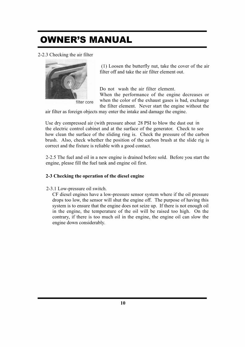
2-2.3 Checking the air filter
(1) Loosen the butterfly nut, take the cover of the airfilter off and take the air filter element out.
Do not wash the air filter element.When the performance of the engine decreases orwhen the color of the exhaust gases is bad, exchangethe filter element. Never start the engine without the
air filter as foreign objects may enter the intake and damage the engine.
Use dry compressed air (with pressure about 28 PSI to blow the dust out inthe electric control cabinet and at the surface of the generator. Check to seehow clean the surface of the sliding ring is. Check the pressure of the carbonbrush. Also, check whether the position of the carbon brush at the slide rig iscorrect and the fixture is reliable with a good contact.
2-2.5 The fuel and oil in a new engine is drained before sold. Before you start theengine, please fill the fuel tank and engine oil first.
2-3 Checking the operation of the diesel engine
2-3.1 Low-pressure oil switch.CF diesel engines have a low-pressure sensor system where if the oil pressuredrops too low, the sensor will shut the engine off. The purpose of having thissystem is to ensure that the engine does not seize up. If there is not enough oilin the engine, the temperature of the oil will be raised too high. On thecontrary, if there is too much oil in the engine, the engine oil can slow theengine down considerably.

11
OWNER’S MANUAL
2-3.3 Engine break in
When you purchase a brand new engine, the engine must be properly brokenin. The break in period is about 20 hours.
(1) Avoid overloading the engine when brand new(2) Change the engine oil according to specifications. An oil change for a
brand new engine is about 20 hours or every month, an older engine, theoil change is about 100 hours or three months.
2-4 Starting the generator set
2-4.1 Manual starting.Start the engine in accordance with procedures below:
(1) Put the fuel switch in the “On” position.(2) Turn the handle of the engine to the “RUN” position.(3) Pull the recoil starter handle out untilyou feel resistance. It will reset to its original positionautomatically. The handleshould be reset into its recoil device slowly toprolong the life of the engine starter.(4) In cold climate, it is difficult to start the engine.To remedy this, pull the rubber plug out from therocker of the diesel engine and fill 1/2 a cap fulloil. Before starting, put the rubber plug back inplace. If you don’t put the rubber plug back in place,rain, dust and other dirt can enter into the diesel engine. It will cause the parts inside the diesel engine to wear quickly and lead to engine failure.
Rubber plug
of engine
2-4.2 Electric starting
The procedures for preparing to start the engine are the same as the manual startingengine.
2-4.3 Battery
1. Insert key into ignition and put it in the “off” position.2. Put the speed handle in the “Run” position.3. Turn the start switch clockwise to the “START” position; to set the silent
type, first turn it clockwise to the “RUN” (ON) position for 1-2 seconds.
12
OWNER’S MANUAL
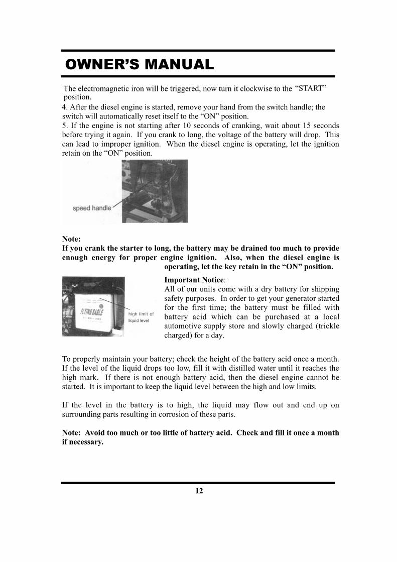
The electromagnetic iron will be triggered, now turn it clockwise to the “START”
4. After the diesel engine is started, remove your hand from the switch handle; the switch will automatically reset itself to the “ON” position.5. If the engine is not starting after 10 seconds of cranking, wait about 15 secondsbefore trying it again. If you crank to long, the voltage of the battery will drop. Thiscan lead to improper ignition. When the diesel engine is operating, let the ignitionretain on the “ON” position.
Note:If you crank the starter to long, the battery may be drained too much to provideenough energy for proper engine ignition. Also, when the diesel engine is
operating, let the key retain in the “ON” position.
Important Notice:All of our units come with a dry battery for shippingsafety purposes. In order to get your generator startedfor the first time; the battery must be filled withbattery acid which can be purchased at a localautomotive supply store and slowly charged (tricklecharged) for a day.
To properly maintain your battery; check the height of the battery acid once a month.If the level of the liquid drops too low, fill it with distilled water until it reaches thehigh mark. If there is not enough battery acid, then the diesel engine cannot bestarted. It is important to keep the liquid level between the high and low limits.
If the level in the battery is to high, the liquid may flow out and end up onsurrounding parts resulting in corrosion of these parts.
Note: Avoid too much or too little of battery acid. Check and fill it once a monthif necessary.
position.

13
OWNER’S MANUAL
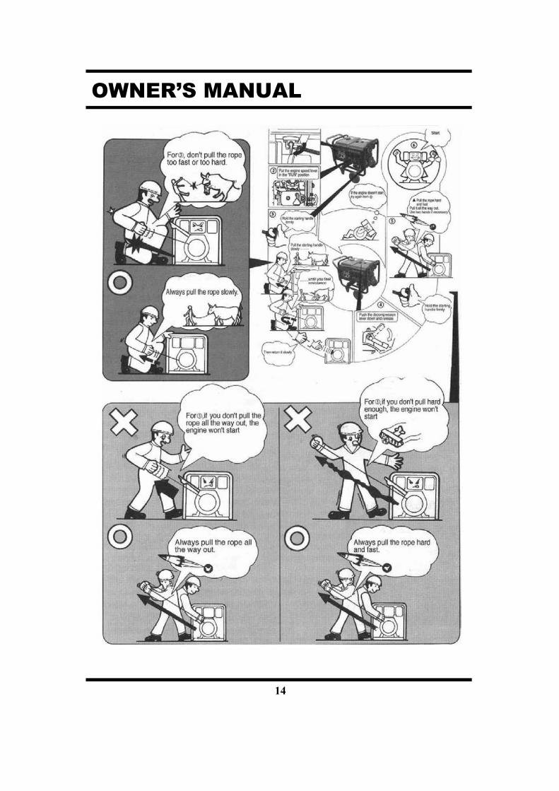
2-5 Procedures for starting the generatorThis procedure applies to the CF series recoil starting style models.
Open the fuel valve
14
OWNER’S MANUAL

15
OWNER’S MANUAL
2-6 Proper operation of the generator
2-6.1 Operating the diesel engine
1. Pre-heat the diesel engine for 3minutes under no load conditions.
2. First check the height of thelubricating oil level, if it islow, refill it. Our dieselengines are equipped withan oil switch that willnotify you if the oil pressureis too low. The system will
pressures too low.
3. Do not adjust the speed limitregulation bolt or the fuel adjustment bolt.These bolts have been set by thefactory already, changing them will affect the properties of the engineperformance.
2-6.2 Checks during engine operation
1. Check to see if there are abnormal noises.2. Check to see if the performance is good or bad3. Check the color of the exhaust gases (whether it is too black or too white).
If any of these conditions exist, stop the engine and find the cause of theproblem. If no problems are found, please contact your local dealer or ournearest company branch.
2-7 Loading
2-7.1 Load conditionsExert loads in accordance with the specified parameters.
shut down the engine if the oil
2-7.2 Output of electricity1. Raise the revolutions per minute (turn the speed handle to the max setting) of thegenerator to get the maximum power out of the generator. If not, theautomatic voltage regulator device will excite and doing this for long periods of timewill cause the AVR to burn. For the rated speed of the generator, please refer toChapter 1, item 1-1 technical specification and data.2. Observe the pointer of the voltmeter, it should point to 240 (60Hz). Meanwhileput the switch in the GEN (generator) position. The AC voltage from the socket ofthe power supply can be output.3. When connecting devices to the generator, make sure to connect these devices in order.

16
OWNER’S MANUAL
Connect the large loads onto the generator first. If everything is functional, smaller loads can thenbe added. If the generator shuts off, it may be because the load being drawn by all the variousdevices are too high. In this event, decrease the number of small devices until everything isfunctional. The total drawn power should not exceed the maximum output power of the generator.Please see Table 1-1 for technical specifications of what the generator can output. In order to resetthe generator after overdrawn power, let it sit for several minutes. If the indication of thevoltmeter is too high or too low, adjust the speed accordingly. If there are problems, stop thegenerator immediately and fix the issue.4. During operation, the generator should be in a place that has very good ventilation.Never cover the engine to solve a ventilation problem, as this will damage yourequipment.
Note: Do not start more than two devices simultaneously. Each device should bestarted one by one to prevent overloading the generator.The generator should be running at 3600 revolutions per minute in order toachieve the (60 Hz) frequency. The speed of the engine can be adjusted from thespeed governor.
2-7.3 Charging the battery1. For the electric starter on the generator sets, the 12V battery is automaticallycharged through the regulator on the side of the engine when it is running.2. If the generator is not used for long periods of time, the battery should bedisconnected to avoid energy loss from the battery.3. Do not connect the negative and positive terminals of the battery together at anytime. Doing so will cause the battery to explode and cause serious injuries.4. Do not reverse the polarities when attaching the battery cables to the battery.Doing so will damage both the battery and the electric starter.5. When charging the battery, the battery produces flammable gases. Do only on well
Do not smoke, let flames, and sparks get near the battery while it is charging as this may cause a fire.To avoid sparking while connecting the cables to the battery, first, connect the cablesto the battery then to the motor. To disconnect battery cables, first disconnect themotor end of the cable.
ventilated area.

17
OWNER’S MANUAL
1. If the speed handle is in the “Stop position and the engine is still running , turn thefuel switch to the “OFF” position or loosen the high pressure oil pipe nut. The enginecould be stopped more than one-wayother than the speed handle way.
2. If you cannot stop the engine with a load on it, then remove the load first than stopthe engine.
3. Press down on the brake handle4. If equipped with an electric starter , turn the key to the “Of f” position5. Put the fuel handle to the “S” position6. Finally, pull slowly on the recoil handle until you feel resistance (this is when the
piston is on the compression stroke, where the intake and exhaust valves are closed).What this does is prevent the engine from rusting when not in use.
2-8 Stopping the generator
1. Take the electrical load of f thegenerator.
2. Put the speed handle in the “RUN”position and let the engine run for 3minutes after unloading. Do not stop theengine immediately let it warm down.Stopping the diesel engine suddenly maythe temperature of the engine abnormallylock the nozzle and damage the dieselengine.

18
OWNER’S MANUAL
CHAPTER 3 MAINTENANCE3-1 Maintenance schedules
Keeping your generator well maintained will prolong the life of your generator. Everything needs to bechecked including the diesel engine, generator, control cabinet, and frame.
Before starting the maintenance, make sure the diesel engine is off.Please refer to the Table 3-1 for the proper maintenance schedule.
timeitem
EverydayAfter 1 monthor 50hours
Every 3 month or200 hours
Every 6 month or 400hours
Every 1year or1000 hours
Check the fuel level andrefill
_Beforestarting
Drain the fuel tank _Check and fill enoughengine oil
_
Clean the fuel filter _
Check fuel oil leakage_after everyoperating
Check and screw eachfastered part
__screw the bolt ofcylinder head firmly
Check injector _Check injection pump _
Cheak fuel pipe_If necessary exchangeit
Check the lube. oil level inthe oil pan and refill
_beforestarting
Replace the lube. oil _the first time_the second time andafterward
Clean lube. Oil filter _the first time_the second time andafterward
Check the air cleanerelement
_the first time_the second time andafterward
Change the core of air filter If damaged or smeary , change it in timeCheck the battery liquidlevel and refill
_
Adjusting the intake andexhaust valve clearance
_the first time_the second time andafterward
Grind air intake and airexhausted gate
_
Exchange piston ring _Check electric brush andslide ring
_
Check insulation resistance The time of stop is over 10 days _

19
OWNER’S MANUAL
3-1.1 Changing the engine oil (every 200 hours)
Take the oil cover off. Remove the oildrain plug when the diesel engine is stillhot. Be careful of hot oil and hot engineas you may get burned. The bolt islocated at the bottom of the cylinder.After draining the oil, put the bolt backand tighten it. Then fill with the properengine oil to the proper level.
3-1.2 Air filter maintenance schedule
1. Clean air-filter every 6 months or 400 hours of operation.2. If necessary, exchange it.
3. Do not use detergent to clean air filter element.Note:
Never start the engine without the air filter.This can cause serious damage to the engine ifforeign objects enter the intake system.Always change the air filter on time.3-1.3 Fuel filter maintenance
1. The fuel filter should be cleaned often to keep the engine running at maximumperformance.
2. The recommended time period for cleaning the fuel filter is 6 months or 400hours of operation.
a. To do this, first drain the fuel from the fuel tank.
b. Loosen the small screws on the fuel switch and remove the fuel filterform the port. Use diesel fuel to clean the fuel filter. Also, remove thefuel injector and clean the carbon deposit around it. The recommendedtime period for this is 3 months or 200 hours.
3-1.4 Cylinder head bolt tensions
The cylinder head bolts should be tightened to specifications please refer to thediesel engine manual for specifications and the special tools required to dothis.

20
OWNER’S MANUAL
3-1.5 Battery check
Make sure the battery acid is full. The engine uses a 12V battery. Due tonumerous starting cycles, the battery acid may be used up. Also, beforefilling, verify that the battery is not damaged in any way. Add distilled waterto the battery when filling. Perform checks on the battery once a month.
3-2 Storing for long periods of time
If your generator needs to be stored for long periods of time, the followingpreparations should be made.
1. Start the diesel engine for 3 minutes then stop it.
2. When the engine is still warm, change the engine oil with new engine oil of theproper grade.
3. Pull the rubber plug out of the cylinder head cover and put 2CC of lubricatingoil in it, then cover the plughole up again.
4. For manual starting generator welders, press the decompression handle downand pull the recoil handle 2 or 3 times. This pushes the intake out. (Do notstart the engine)
5. For electric started generator welders, press the decompression handle downand crank the engine for 2-3 seconds. To do this, put the starter switch in the“Start” position. (Do not start the diesel engine)
6. Finally, pull the recoil starter until you feel resistance; this is when the piston ison the compression stroke where the intake and exhaust valves are closed.Having the intake and exhaust valves closed will prevent rust, as moisturecannot get inside the combustion chamber.
7. Clean the engine and store it in a dry place.

21
OWNER’S MANUAL
4-1 Questions and doubts
If you do not understand anything or have any questions, please feel free tocontact your local dealer or with our company directly. Below is a list of someinformation you should have ready before contacting your local dealer or us.
1. Model of diesel engine generator and engine model number.2. State of residency3. Number of hours of operating equipment along with the problem that occurred.4. A detailed condition and time when the problem occurred, in other words,
climate and atmosphere5. Original receipt6. Serial #

22
OWNER’S MANUAL
CHAPTER 5 GENERATOR PARTS DIAGRAMS AND LISTINGSFigure 5-1.
Table 5-1.Number Part Description Quantity Part Number
(CFA6500CXE)1 CFeries diesel engine 1 CFA6500CXE1
2 Starter Motor 1 CFA6500CXE23 Flywheel generator 1 CFA6500CXE34 Bolt 2 CFA6500CXE45 Voltage Regulator 1 CFA6500CXE56 Battery Cable (red) 1 CFA6500CXE6
7 Battery Cable (black) 1 CFA6500CXE7
8 Battery 1 CFA6500CXE8
9 Oil level sensor 1 CFA6500CXE9
10 Output panel assembly 1 CFA6500CXE1011 Throttle cable 2 CFA6500CXE1112 Connector assembly 1 CFA6500CXE1213 Capacitor 1 CFA6500CXE1314 Bolt 2 CFA6500CXE14
15Voltage Regulator
Bracket 1 CFA6500CXE15
16 Bolt 2 CFA5500CXE16

23
OWNER’S MANUAL
Table 5-2.
Number Part Description Quantity Part Number (CFA6500CXE)1 M6 x 25 Bolt 4 CFA6500CXE172 M6 Flat washer 4 CFA6500CXE183 Shock absorber 4 CFA6500CXE194 Washer 4 CFA6500CXE205 M6 Nut 4 CFA6500CXE216 Engine cover 1 CFA6500CXE227 Rubber cover 1 CFA6500CXE238 Handrail 1 CFA6500CXE249 M8 x 65 Bolt 4 CFA6500CXE2510 Plastic gasket 4 CFA6500CXE2611 Flat washer M8 4 CFA6500CXE2712 Spring washer 4 CFA6500CXE2813 M8 Nut 4 CFA6500CXE2914 Battery tie down 1 CFA6500CXE3015 M6 Nut 2 CFA6500CXE3116 Tie down hooks 2 CFA6500CXE32
24
OWNER’S MANUAL
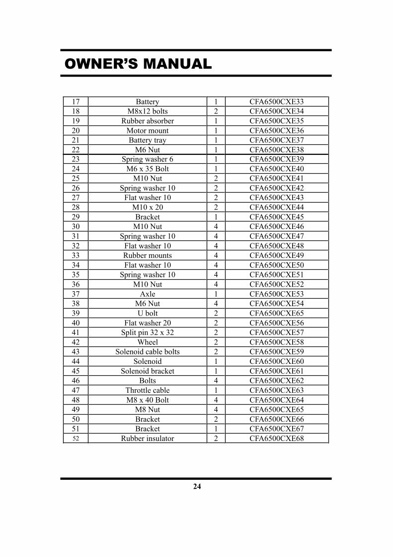
17 Battery 1 CFA6500CXE3318 M8x12 bolts 2 CFA6500CXE3419 Rubber absorber 1 CFA6500CXE3520 Motor mount 1 CFA6500CXE3621 Battery tray 1 CFA6500CXE3722 M6 Nut 1 CFA6500CXE3823 Spring washer 6 1 CFA6500CXE3924 M6 x 35 Bolt 1 CFA6500CXE4025 M10 Nut 2 CFA6500CXE4126 Spring washer 10 2 CFA6500CXE4227 Flat washer 10 2 CFA6500CXE4328 M10 x 20 2 CFA6500CXE4429 Bracket 1 CFA6500CXE4530 M10 Nut 4 CFA6500CXE4631 Spring washer 10 4 CFA6500CXE4732 Flat washer 10 4 CFA6500CXE4833 Rubber mounts 4 CFA6500CXE4934 Flat washer 10 4 CFA6500CXE5035 Spring washer 10 4 CFA6500CXE5136 M10 Nut 4 CFA6500CXE5237 Axle 1 CFA6500CXE5338 M6 Nut 4 CFA6500CXE5439 U bolt 2 CFA6500CXE6540 Flat washer 20 2 CFA6500CXE5641 Split pin 32 x 32 2 CFA6500CXE5742 Wheel 2 CFA6500CXE5843 Solenoid cable bolts 2 CFA6500CXE5944 Solenoid 1 CFA6500CXE6045 Solenoid bracket 1 CFA6500CXE6146 Bolts 4 CFA6500CXE6247 Throttle cable 1 CFA6500CXE6348 M8 x 40 Bolt 4 CFA6500CXE6449 M8 Nut 4 CFA6500CXE6550 Bracket 2 CFA6500CXE6651 Bracket 1 CFA6500CXE6752 Rubber insulator 2 CFA6500CXE68

25
OWNER’S MANUAL
Figure 5-3.
Table 5-3.
Number Part Description QuantityPart Number
(CFA6500CXE)1 Positive DC port 1 CFA6500CXE692 Negative DC port 1 CFA6500CXE703 Grounded bolt 1 CFA6500CXE714 Bolt 2 CFA6500CXE725 Large Nut 1 CFA6500CXE736 Bolt 2 CFA6500CXE747 Bolt 2 CFA6500CXE758 Large Nut 1 CFA6500CXE76
9Current Adjusting
Switch 1 CFA6500CXE77
10 3 prong Socket 2 CFA6500CXE7811 Bolt 6 CFA6500CXE7912 Electric panel bolt 6 CFA6500CXE8013 Electric Panel 1 CFA6500CXE8114 Starter switch 1 CFA6500CXE8215 Large nut 6 CFA6500CXE8316 Oil alert lamp 1 CFA6500CXE84
26
OWNER’S MANUAL
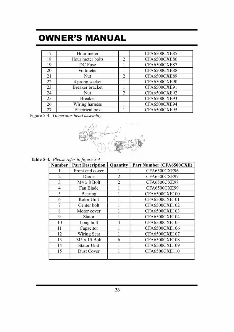
17 Hour meter 1 CFA6500CXE8518 Hour meter bolts 2 CFA6500CXE8619 DC Fuse 1 CFA6500CXE8720 Voltmeter 1 CFA6500CXE8821 Nut 2 CFA6500CXE8922 4 prong socket 1 CFA6500CXE9023 Breaker bracket 1 CFA6500CXE9124 Nut 2 CFA6500CXE9225 Breaker 1 CFA6500CXE9326 Wiring harness 1 CFA6500CXE9427 Electrical box 1 CFA6500CXE95
Figure 5-4.
Table 5-4.Number Part Description Quantity Part Number (CFA6500CXE)
1 Front end cover 1 CFA6500CXE962 Diode 2 CFA6500CXE973 M4 x 8 Bolt 2 CFA6500CXE984 Fan Blade 1 CFA6500CXE995 Bearing 1 CFA6500CXE1006 Rotor Unit 1 CFA6500CXE1017 Center bolt 1 CFA6500CXE1028 Motor cover 1 CFA6500CXE1039 Stator 1 CFA6500CXE10410 Long bolt 4 CFA6500CXE10511 Capacitor 1 CFA6500CXE10612 Wiring Seat 1 CFA6500CXE10713 M5 x 15 Bolt 6 CFA6500CXE10814 Stator Unit 1 CFA6500CXE10915 Dust Cover 1 CFA6500CXE110

27
OWNER’S MANUAL
Figure 5-5. Fuel system components
Table 5-5.Number Part Description Quantity Part Number (CFA6500CXE)
1 Fuel Cap 1 CFA6500CXE1112 Seal 1 CFA6500CXE1123 Filtering cup 1 CFA6500CXE1134 M5 x 10 screw 2 CFA6500CXE1145 Fuel lever indicator 1 CFA6500CXE1156 M6 x 25 Bolt 4 CFA6500CXE1167 Large flat washer 6 4 CFA6500CXE1178 Fuel tank lining 4 CFA6500CXE1189 Shock absorbing gasket 4 CFA6500CXE11910 Fuel tank 1 CFA6500CXE12011 M6 Nut 4 CFA6500CXE12112 O ring seal 1 CFA6500CXE12213 Fuel tank filter 1 CFA6500CXE12314 O ring gasket 1 CFA6500CXE12415 Fuel filter cover 1 CFA6500CXE125
16 Cover 1 CFA6500CXE126

28
OWNER’S MANUAL
17 Wing nut 1 CFA6500CXE12718 Fuel line 2 CFA6500CXE12819 Fuel inlet pipe 1 CFA6500CXE12920 High pressure fuel pump 1 CFA6500CXE13021 High pressure fuel pipe 1 CFA6500CXE13122 Fuel injector 1 CFA6500CXE13223 Overfill tube 2 CFA6500CXE13324 Fuel overfill pipe 1 CFA6500CXE134
29
OWNER’S MANUAL
Limited Warranty
All-Power America warrants to the original purchaser who uses the product in aconsumer application (personal, residential or household usage) that all productscovered under this Warranty are free from defects in material and workmanship forone year from the date of purchase. All products covered by this limited Warrantywhich are used in commercial applications (i.e. income producing) are warranted tobe free of defects in material and workmanship for 90 days from the date of originalpurchase. Products covered under this Warranty include air compressors, air tools,service parts, pressure washers and generators.
All-Power America will repair or replace at All-Power America's sole option,products or components which have failed within the warranty period. Service will bescheduled according to the normal work flow and business hours at the service centerlocation, and the availability of replacement parts. All decisions of All- PowerAmerica with regard to this limited warranty shall be final.
This warranty gives you specific legal rights, and you may also have other rightswhich vary from state to state.RESPONSIBILITY OF ORIGINAL PURCHASER (Initial User):
To process a warranty claim on this product, DO NOT return item to the retailer.The product must be evaluated by an Authorized Warranty Service Center. For thelocation of the nearest Authorized Warranty Service Center contact the retailer orplace of purchase.
Retain original cash register sales receipt as proof of purchase for warranty work.
Use reasonable care in the operation and maintenance of the product as describedin the Owner’s Manual(s).
Deliver or ship the product to the nearest Authorized Warranty Service Center.Freight costs, if any, must be paid by the purchaser.Air compressors with 60 and 80 gallon tanks will be inspected at the site ofinstallation. Contact the nearest Authorized Warranty Service Center that provideson-site service calls for service call arrangements.
If the purchaser does not receive satisfactory results from the Authorized WarrantyService Center, the purchaser should contact All-Power America.

30
OWNER’S MANUAL
Limited Warranty (cont’d)
THIS WARRANTY DOES NOT COVER:Merchandise sold as reconditioned, used as rental equipment, or floor ordisplay models.Merchandise that has become damaged or inoperative because of ordinarywear, misuse, cold, heat, rain, excessive humidity, freeze damage, use ofimproper chemicals, negligence, accident, failure to operate the productin accordance with the instructions provided in the Owner’s Manual(s)supplied with the product, improper maintenance, the use of accessoriesor attachments not recommended by All-Power America, orunauthorized repair or alterations.
Repair and transportation costs of merchandise determined not to be defective.Costs associated with assembly, required oil, adjustments or otherinstallation and start-up costs.
Expendable parts or accessories supplied with the product which areexpected to become inoperative or unusable after a reasonable period ofuse.
Merchandise sold by All-Power America which has been manufactured byand identified as the product of another company, such as gasolineengines. The product manufacturer's Warranty, if any, will apply.
ANY INCIDENTAL, INDIRECT OR CONSEQUENTIAL LOSS,DAMAGE, OR EXPENSE THAT MAY RESULT FROM ANYDEFECTS, FAILURE OR MALFUNCTION OF THE PRODUCT IS NOTCOVERED BY THIS WARRANTY. Some states do not allow theexclusion, so it may not apply to you.
IMPLIED WARRANTIES, INCLUDING THOSE OFMERCHANTABILITY OR FITNESS FOR A PARTICULAR PURPOSE,ARE LIMITED TO ONE YEAR FROM THE DATE OF ORIGINALPURCHASE. Some states do not allow limitations on how long an impliedwarranty lasts, so the above limitations may not apply.