OWNER’S MANUAL 193111-049
39
OWNER’S MANUAL 193111-049 Revised December 10, 2008 IMPORTANT: Read these instructions before installing, operating, or servicing this system. POWER PRO FERRO 100 SERIES CHARGERS Silicon Diode Ferroresonant Transformer Type Battery Charger DO NOT DESTROY
Transcript of OWNER’S MANUAL 193111-049

OWNER’S MANUAL 193111-049
Revised December 10, 2008
IMPORTANT: Read these instructions before installing, operating, or servicing this system.
POWER PRO FERRO 100 SERIES CHARGERS
Silicon Diode Ferroresonant Transformer Type Battery Charger
DO NOT DESTROY

NOTE: Information regarding obtaining additional copies of this manual is located in the Introduction chapter of this manual. A battery charger is identified by model number. Incorporated into the model number is the 8-hour ampere-hour capacity, case size, input power phase, and number of cells in battery for which charger is intended. The following example explains the basic model numbering arrangement. Model 12 - 750 FR 100 T 3 Phase Input Power 100% Rated Suffix Ferroresonant Ampere-Hour Capacity in 8 Hours Number of Cells NOTE: This information is required for ordering certain replacement/service parts.
193111-049 TABLE OF CONTENTS
INTRODUCTION ........................................................................................................................................1 How to use this Manual ......................................................................................................................1-1 Equipment Identification .....................................................................................................................1-1 Receipt of Equipment .........................................................................................................................1-1
SAFETY INSTRUCTIONS AND WARNINGS............................................................................................2 INITIAL SET-UP & DESCRIPTION............................................................................................................3 INSTALLATION .........................................................................................................................................4
Location ..............................................................................................................................................4-1 Environmental Characteristics............................................................................................................4-1 Grounding...........................................................................................................................................4-1 Line Voltage Changeover Instructions ...............................................................................................4-2 Line Connections to Battery Charger .................................................................................................4-2 Charging Cable Connectors ...............................................................................................................4-3 Pre-operation Checks.........................................................................................................................4-3
OPERATION ..............................................................................................................................................5
Preliminary..........................................................................................................................................5-1 Normal or Daily Charge .....................................................................................................................5-1 Equalize or Weekend Charge ............................................................................................................5-2 Manual Stop .......................................................................................................................................5-2 Refresh Charge ..................................................................................................................................5-2 Backup Timer Shutdown ....................................................................................................................5-2 Battery Disconnect Shutdown ............................................................................................................5-2 AC Power Fail.....................................................................................................................................5-2
MAINTENANCE .........................................................................................................................................6 Inspection and Cleaning.....................................................................................................................6-1 Lubrication ..........................................................................................................................................6-1 Fuse Replacement .............................................................................................................................6-1 Silicon Diode Testing..........................................................................................................................6-1 Capacitor Testing ...............................................................................................................................6-2 Troubleshooting..................................................................................................................................6-3
3 PHASE PARTS LIST ..............................................................................................................................7 1 PHASE PARTS LIST ..............................................................................................................................8 WARRANTY
August 9, 2002 Page 1

193111-049 INTRODUCTION
August 9, 2002 1-1
INTRODUCTION How To Use This Manual IMPORTANT: It is especially important that all charger internal components be kept clean and dry, and all electrical connections as tightened as instructed in the Maintenance chapter of this manual. Replace any precautionary or instruction label that cannot be easily read. Throughout this manual, the words WARNING, CAUTION, and NOTE may appear. Pay particular attention to the information provided under these headings. These special annotations are easily recognized as follows: WARNING gives information regarding possible personal injury. Warnings will be enclosed in a box such as this. CAUTION refers to possible equipment damage. Cautions will be shown in bold type.
NOTE offers helpful information concerning certain operating procedures. Notes will be shown in italics. Equipment Identification The unit's identification number (specification, model, serial number) usually appears on a nameplate attached to the front panel. Receipt Of Equipment When you receive the equipment, check it against the invoice to make sure it is complete and inspect the equipment for possible damage due to shipping. If there is any damage, notify the carrier immediately to file a claim. Furnish complete information concerning damage claims or shipping errors to the company shown on the cover of this manual. Include all equipment identification numbers and group part numbers (if any) as described above along with a full description of the parts in error. Move the equipment to the site of installation before uncrating. Use care to avoid damaging the equipment when using bars, hammers, etc., to uncrate the unit. Additional copies of this manual may be purchased by contacting Ametek/Prestolite Power Troy OH 45373, include the Owner's Manual number and equipment identification numbers.
August 9, 2002 2-1
193111-049 SAFETY INSTRUCTIONS AND WARNINGS
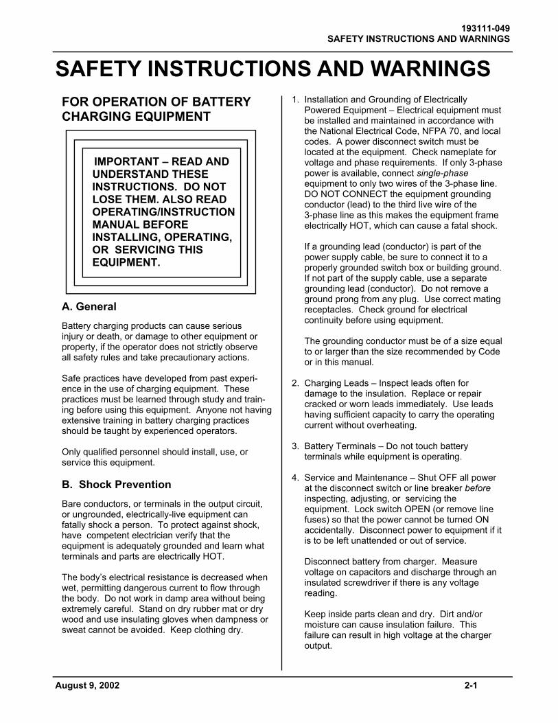
SAFETY INSTRUCTIONS AND WARNINGS FOR OPERATION OF BATTERY CHARGING EQUIPMENT IMPORTANT – READ AND UNDERSTAND THESE INSTRUCTIONS. DO NOT LOSE THEM. ALSO READ OPERATING/INSTRUCTION MANUAL BEFORE INSTALLING, OPERATING, OR SERVICING THIS EQUIPMENT. A. General Battery charging products can cause serious injury or death, or damage to other equipment or property, if the operator does not strictly observe all safety rules and take precautionary actions. Safe practices have developed from past experi-ence in the use of charging equipment. These practices must be learned through study and train-ing before using this equipment. Anyone not having extensive training in battery charging practices should be taught by experienced operators. Only qualified personnel should install, use, or service this equipment. B. Shock Prevention Bare conductors, or terminals in the output circuit, or ungrounded, electrically-live equipment can fatally shock a person. To protect against shock, have competent electrician verify that the equipment is adequately grounded and learn what terminals and parts are electrically HOT. The body’s electrical resistance is decreased when wet, permitting dangerous current to flow through the body. Do not work in damp area without being extremely careful. Stand on dry rubber mat or dry wood and use insulating gloves when dampness or sweat cannot be avoided. Keep clothing dry.
1. Installation and Grounding of Electrically Powered Equipment – Electrical equipment must be installed and maintained in accordance with the National Electrical Code, NFPA 70, and local codes. A power disconnect switch must be located at the equipment. Check nameplate for voltage and phase requirements. If only 3-phase power is available, connect single-phase equipment to only two wires of the 3-phase line. DO NOT CONNECT the equipment grounding conductor (lead) to the third live wire of the 3-phase line as this makes the equipment frame electrically HOT, which can cause a fatal shock. If a grounding lead (conductor) is part of the power supply cable, be sure to connect it to a properly grounded switch box or building ground. If not part of the supply cable, use a separate grounding lead (conductor). Do not remove a ground prong from any plug. Use correct mating receptacles. Check ground for electrical continuity before using equipment. The grounding conductor must be of a size equal to or larger than the size recommended by Code or in this manual. 2. Charging Leads – Inspect leads often for damage to the insulation. Replace or repair cracked or worn leads immediately. Use leads having sufficient capacity to carry the operating current without overheating. 3. Battery Terminals – Do not touch battery terminals while equipment is operating. 4. Service and Maintenance – Shut OFF all power at the disconnect switch or line breaker before inspecting, adjusting, or servicing the equipment. Lock switch OPEN (or remove line fuses) so that the power cannot be turned ON accidentally. Disconnect power to equipment if it is to be left unattended or out of service. Disconnect battery from charger. Measure voltage on capacitors and discharge through an insulated screwdriver if there is any voltage reading. Keep inside parts clean and dry. Dirt and/or moisture can cause insulation failure. This failure can result in high voltage at the charger output.
193111-049 SAFETY INSTRUCTIONS AND WARNINGS
2-2 August 9, 2002
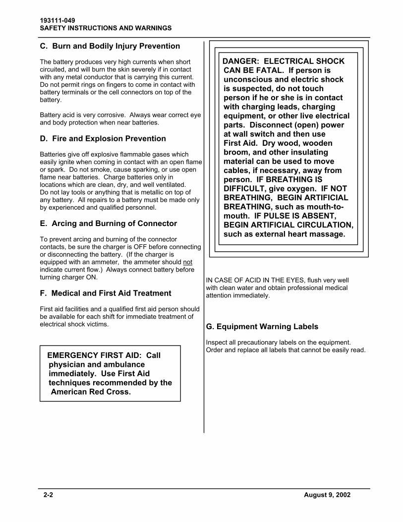
C. Burn and Bodily Injury Prevention The battery produces very high currents when short circuited, and will burn the skin severely if in contact with any metal conductor that is carrying this current. Do not permit rings on fingers to come in contact with battery terminals or the cell connectors on top of the battery. Battery acid is very corrosive. Always wear correct eye and body protection when near batteries. D. Fire and Explosion Prevention Batteries give off explosive flammable gases which easily ignite when coming in contact with an open flame or spark. Do not smoke, cause sparking, or use open flame near batteries. Charge batteries only in locations which are clean, dry, and well ventilated. Do not lay tools or anything that is metallic on top of any battery. All repairs to a battery must be made only by experienced and qualified personnel. E. Arcing and Burning of Connector To prevent arcing and burning of the connector contacts, be sure the charger is OFF before connecting or disconnecting the battery. (If the charger is equipped with an ammeter, the ammeter should not indicate current flow.) Always connect battery before turning charger ON. F. Medical and First Aid Treatment First aid facilities and a qualified first aid person should be available for each shift for immediate treatment of electrical shock victims. EMERGENCY FIRST AID: Call physician and ambulance immediately. Use First Aid techniques recommended by the American Red Cross.
DANGER: ELECTRICAL SHOCK CAN BE FATAL. If person is unconscious and electric shock is suspected, do not touch person if he or she is in contact with charging leads, charging equipment, or other live electrical parts. Disconnect (open) power at wall switch and then use First Aid. Dry wood, wooden broom, and other insulating material can be used to move cables, if necessary, away from person. IF BREATHING IS DIFFICULT, give oxygen. IF NOT BREATHING, BEGIN ARTIFICIAL BREATHING, such as mouth-to- mouth. IF PULSE IS ABSENT, BEGIN ARTIFICIAL CIRCULATION, such as external heart massage. IN CASE OF ACID IN THE EYES, flush very well with clean water and obtain professional medical attention immediately. G. Equipment Warning Labels Inspect all precautionary labels on the equipment. Order and replace all labels that cannot be easily read.

193111-049 INITIAL SET-UP & DESCRIPTION
August 9, 2002 3-1
INITIAL SET-UP & DESCRIPTION Charger
The basic charging circuit is the silicon diode, rectifier-type with ferroresonant transformer (s). This ferroresonant transformer design regulates charging current by allowing the battery to determine its own charge cycle rate in accordance with its state of discharge. It provides a constantly-tapering charge that eliminates the possibility of overcharging, even with line voltage variations of ± 10%. Single-phase input chargers have one transformer, three-phase input chargers have two. The charger is internally protected from overload and short circuits. When charging lead acid batteries, with the same number of cells and ampere-hour capacity as shown on charger nameplate, the charging time will be approximately 8 hours. Batteries of smaller or larger ampere-hour capacities can also be charged, but will require shorter or longer charging, respectively.
WARNING: Do not connect a battery to this charger if any LED is lit. Do not disconnect a battery from this charger while a charge is in progress. Otherwise, arcing and burning of connector parts or a battery explosion may result. Batteries produce explosive gases. Keep sparks, flame, and cigarettes away. Ventilate when charging in an enclosed area. Always shield eyes when working near batteries. Set-Up
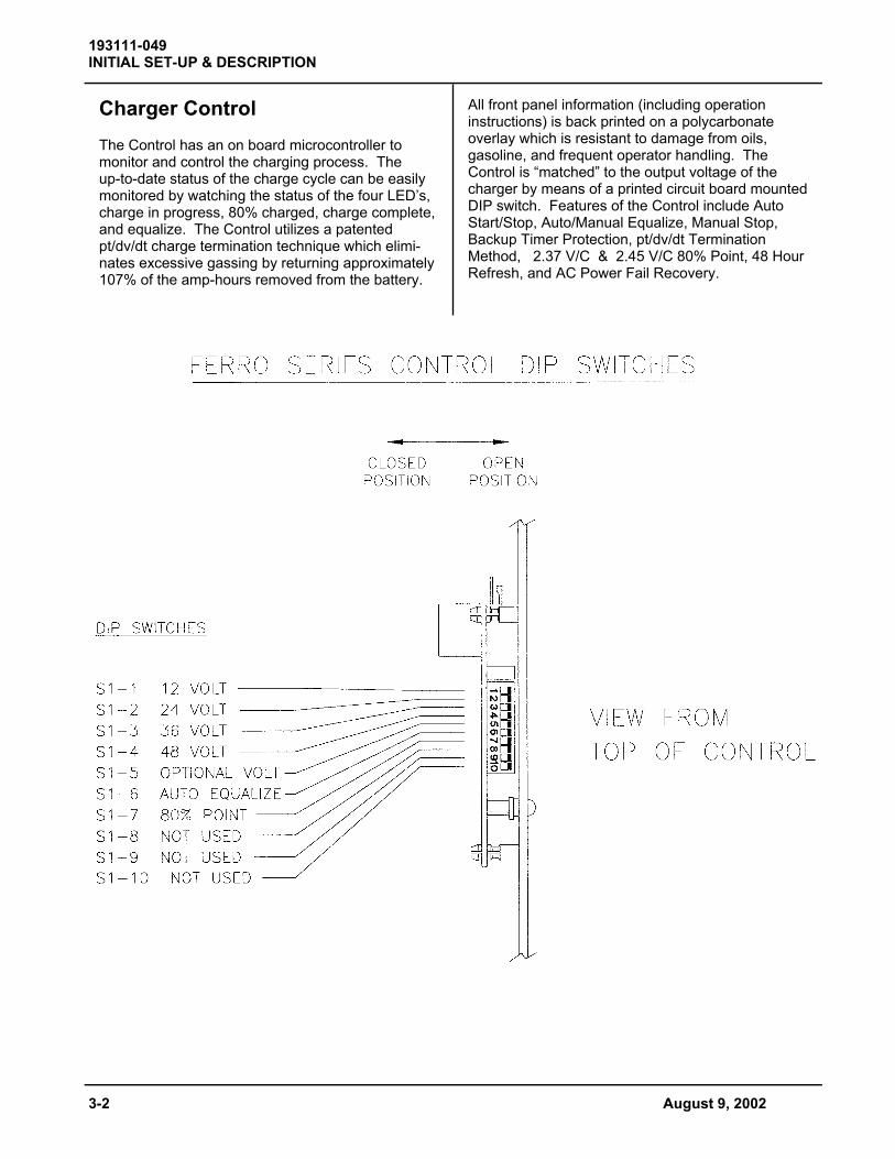
See Location Diagram of Selector Switches in-cluded in this manual. For proper operation, the Control must be set to match the charger in which it is installed.
Cell Size Selection From the data plate on the charger, note the voltage output. Place the corresponding DIP switch (S1) on the Control in the “Closed” position. S1-1 12 Volts S1-2 24 Volts S1-3 36 Volts S1-4 48 Volts S1-5 Optional Only one of the above DIP switches should be in the “Closed” position at any one time. Auto Equalize Switch S1-6 can be used to select either Auto Equalize or Manual Equalize. Termination Type Switch S1-7 can be used to select either 2.37 V/C or 2.45 V/C 80% Trip Point.
S1-6 Equalize Type
Open Auto Equalize every 5th Cycle
Closed Manual Equalize
S1-7 80% V/C
Open 2.37
Closed 2.45
193111-049 INITIAL SET-UP & DESCRIPTION
3-2 August 9, 2002
Charger Control The Control has an on board microcontroller to monitor and control the charging process. The up-to-date status of the charge cycle can be easily monitored by watching the status of the four LED’s, charge in progress, 80% charged, charge complete, and equalize. The Control utilizes a patented pt/dv/dt charge termination technique which elimi-nates excessive gassing by returning approximately 107% of the amp-hours removed from the battery.
All front panel information (including operation instructions) is back printed on a polycarbonate overlay which is resistant to damage from oils, gasoline, and frequent operator handling. The Control is “matched” to the output voltage of the charger by means of a printed circuit board mounted DIP switch. Features of the Control include Auto Start/Stop, Auto/Manual Equalize, Manual Stop, Backup Timer Protection, pt/dv/dt Termination Method, 2.37 V/C & 2.45 V/C 80% Point, 48 Hour Refresh, and AC Power Fail Recovery.

August 9, 2002 4-1
193111-049 INSTALLATION
INSTALLATION Location For best operating characteristics and longest unit life, take care in selecting an installation site. Avoid locations exposed to high humidity, dust, high ambient temperature, or corrosive fumes. Moisture can condense on electrical components, causing corrosion or shorting of circuits (especially when dirt is also present). Adequate air circulation is needed at all times in order to assure proper operation. Provide a minimum of 6 inches of free air space at rear and sides of the unit. Make sure that ventilation openings are not obstructed. Always remove the charger shipping skid from the unit before installation. The charger must be installed over a noncombustible surface such as concrete or metal. Keep the charging area clear of all combustible material such as wood, paper, and cloth. WARNING: SPARKS OR MOLTEN METAL falling through open bottom can cause fire or explosion. • Install over noncombustible material such as
concrete or metal. • Keep charging area clear of combustible
material. Environmental Characteristics Operating Characteristics 0°C to 40°C (32°F to 104°F) Operating Altitude To 2000 Meters (6562 Feet) Operating Humidity 80% up to 31°C, decreasing to 50% at 40°C, non-condensing 80% up to 88°F decreasing to 50% at 104°F, non-condensing Grounding The frame of the power source must be grounded for personnel safety. Where grounding is mandatory under state or local codes, it is the responsibility of the user to comply with all applicable rules and regulations. Where no state or local codes exist, it is recommended that the National Electrical Code be followed.
In addition to the usual function of protecting personnel against the hazard of electrical shock due to fault in the equipment, grounding serves to discharge the static electrical charges which tend to build up on the surfaces of equipment. These static charges can cause painful shock to personnel, and can lead to the erroneous conclusion that an electrical fault exists in the equipment. If a charger is to be connected to the AC power supply with a flexible jacketed cable, one having a separate grounding conductor should be used. When included in cable assembly, grounding conductor will be green, green with a yellow stripe, or bare. When connecting input power to charger (as instructed in Line Connection to Battery Charger section of this manual), connect grounding conductor to equipment grounding terminal (stud with a green nut and a cup washer and identified by symbol ), taking care to make a good electrical connection. Connect other end of grounding conductor to the system ground. If, for any reason, an input cable which does not in-clude a grounding conductor is used, the equipment must be grounded with separate conductor. Minimum size and color coding requirements must be in accor-dance with any applicable state or local code, or the National Electrical Code. If metallic armored cable or conduit is used, the metal sheathing or conduit must be effectively grounded as required by state or local code, or the National Electrical Code. If a system ground is not available, the charger frame must be connected to a driven ground rod (at least 8 ft [2438 mm] long), or to a water pipe that enters the ground not more than 10 ft (3048 mm) from the charger. A grounding conductor must be connected to the rod or pipe in a manner that will assure a permanent and effective ground. The conductor must be sized in accordance with any applicable state or local code, or by the National Electrical Code. If in doubt, use the same size conductor as is used for the conductors supplying power to the charger. WARNING: ELECTRIC SHOCK Hazard - Under no circumstance should you use a grounding conductor with a current carrying capacity less than the ampere rating shown in Table 4-1.
193111-049 INSTALLATION
4-2 August 9, 2002
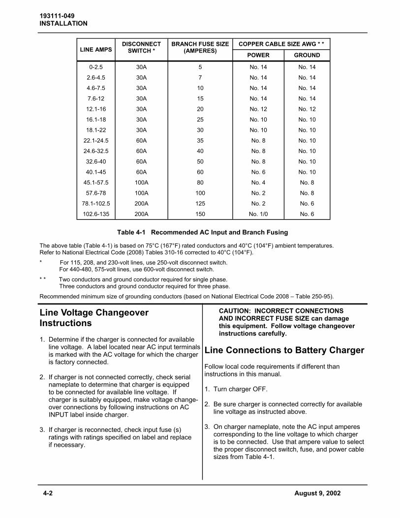
Table 4-1 Recommended AC Input and Branch Fusing
LINE AMPS DISCONNECT
SWITCH * COPPER CABLE SIZE AWG * *
POWER GROUND
0-2.5 30A 5 No. 14 No. 14
2.6-4.5 30A 7 No. 14 No. 14
4.6-7.5 30A 10 No. 14 No. 14
7.6-12 30A 15 No. 14 No. 14
12.1-16 30A 20 No. 12 No. 12
16.1-18 30A 25 No. 10 No. 10
18.1-22 30A 30 No. 10 No. 10
22.1-24.5 60A 35 No. 8 No. 10
24.6-32.5 60A 40 No. 8 No. 10
32.6-40 60A 50 No. 8 No. 10
40.1-45 60A 60 No. 6 No. 10
45.1-57.5 100A 80 No. 4 No. 8
57.6-78 100A 100 No. 2 No. 8
78.1-102.5 200A 125 No. 2 No. 6
102.6-135 200A 150 No. 1/0 No. 6
BRANCH FUSE SIZE (AMPERES)
The above table (Table 4-1) is based on 75°C (167°F) rated conductors and 40°C (104°F) ambient temperatures. Refer to National Electrical Code (2008) Tables 310-16 corrected to 40°C (104°F). * For 115, 208, and 230-volt lines, use 250-volt disconnect switch. For 440-480, 575-volt lines, use 600-volt disconnect switch. * * Two conductors and ground conductor required for single phase. Three conductors and ground conductor required for three phase. Recommended minimum size of grounding conductors (based on National Electrical Code 2008 – Table 250-95).
Line Voltage Changeover Instructions 1. Determine if the charger is connected for available line voltage. A label located near AC input terminals is marked with the AC voltage for which the charger is factory connected. 2. If charger is not connected correctly, check serial nameplate to determine that charger is equipped to be connected for available line voltage. If charger is suitably equipped, make voltage change- over connections by following instructions on AC INPUT label inside charger. 3. If charger is reconnected, check input fuse (s) ratings with ratings specified on label and replace if necessary.
CAUTION: INCORRECT CONNECTIONS AND INCORRECT FUSE SIZE can damage this equipment. Follow voltage changeover instructions carefully. Line Connections to Battery Charger Follow local code requirements if different than instructions in this manual. 1. Turn charger OFF. 2. Be sure charger is connected correctly for available line voltage as instructed above. 3. On charger nameplate, note the AC input amperes corresponding to the line voltage to which charger is to be connected. Use that ampere value to select the proper disconnect switch, fuse, and power cable sizes from Table 4-1.
193111-049 INSTALLATION
August 9, 2002 4-3
4. Route AC power input cable in through knock-out provided in side panel of charger cabinet. Securely fasten cable wires to a power input terminal inside charger. Refer to Grounding section of this manual for proper connection of grounding conductor. (Charger cabinet top or side panel, or both, may have to be removed to provide access to terminal block.) 5. With disconnect switch (on AC input power line) in “OPEN” or “OFF” position, connect power cable coming from charger, to the switch. Install fuses in switch. Charging Cable Connectors If connectors are already attached to charging cables, make sure that they’re attached so that positive charger polarity will connect to positive battery terminal. If connectors must be attached to charging cables, follow instructions supplied with connectors. CAUTION: Make sure connectors are securely attached to cables (good solder joint or well tightened set screws, whichever is applicable). Be certain that positive charger cable will connect to positive battery terminal. If necessary, trace cables into charger and use supplied connection diagram to determine polarity. The use of a DC voltmeter may show polarity. Improper connections will “blow” output fuse and may cause other damage.
Pre-operation Checks 1. Inspect charger thoroughly for damage; loose screws, nuts, or electrical connections. WARNING: ELECTRICAL SHOCK HAZARD – Before inspecting or cleaning inside cabinet, turn OFF and remove fuses of disconnect switch (supplying AC power to charger), disconnect battery, and check for voltage on capacitors. Discharge through insulated screwdriver if there is any reading. 2. Remove all special tags that are tied to charger. Keep tags with this manual for future reference. Leave all precautionary and instruction labels in place on charger. Carefully read and follow instructions on all tags and labels. Make sure all labels remain visible to anyone operating charger. 3. Make sure all charger cabinet panels are fastened in place, to assure proper flow of ventilating air through cabinet.

August 9, 2002 5-1
193111-049 OPERATION
OPERATION A. Preliminary Make sure the charger is installed and grounded as instructed in the INSTALLATION chapter of this manual. Maintain electrolyte level in the batteries to be charged, as instructed by the battery manufacturer. Because the volume of electrolyte expands during the charging process, only add water when the battery is at least 80% charged. An amber light will be illuminated on the charger control panel when the battery is at or above 80% charge. Insure the battery size matches the charger. Battery number of cells must equal the number of cells stated on the charger data plate. Battery ampere-hour capacity must be within the ampere-hour range stated on the charger data plate. WARNING: EXPLOSION HAZARD – Do not connect a battery to this charger if the “Charge in Progress” LED is illuminated on the charger. Do not disconnect a battery from this charger if the “Charge in Progress” LED is illuminated or ammeter is indicating charging current; otherwise, arcing and burning of connector parts can occur or a battery explosion may result. Batteries produce explosive gases. Keep sparks, flames, and cigarettes away. Ventilate when charging in an enclosed area. Always shield eyes using face shield and goggles when working near batteries. CAUTION: The charging of a battery with the incorrect number of cells or an ampere- hour capacity outside the range stated on the charger data plate will result in severe over or under charging of the battery, resulting in reduced battery performance and life.
B. Normal or Daily Charge WARNING: DO NOT connect a battery to this charger if the “Charge in Progress” LED is lit. Do not disconnect a battery from this charger while a charge is in progress; otherwise, arcing and burning of connector parts or a battery explosion may result. Batteries produce explosive gases. Keep sparks, flame, and cigarettes away. Ventilate when charging in an enclosed area. Always shield eyes when working near batteries. 1. Insure the battery size matches the charger (Battery voltage and ampere hour capacity are within nameplate information). 2. Securely engage the battery and charger connectors. 3. After a five second delay (all LED‘s will be lit), the charger will turn on. The “Charge in Progress” LED will indicate charging current. 4. The “80% CHARGED” LED will light when the battery on charge reaches the 80% charged voltage. 5. The charger will automatically turn off and the “Charge Complete” LED will light when the charge has finished. reaching 80% charge. The light will remain on until the battery is disconnected from the charger. NOTE: To disconnect battery from charger before charge is complete, first press the “Manual Stop” key, then disconnect the battery from the charger.

5-2 August 9, 2002
193111-049 OPERATION
C. Equalize Or Weekend Charge The Control features Auto Equalize on every 5th charge cycle. Closing S1-6 can disable the feature. When the Auto Equalize feature is disabled, an Equalize charge can be selected or de-selected for any charge cycle using the sequence below. 1. Insure the battery size matches the charger. (Number of cells and ampere-hour capacity are within charger nameplate rating.) 2. Securely engage the battery and charger connectors. 3. After a 5 second delay (all LED’s will be lit), the charger will turn on. The “Charge in Progress” LED will indicate charging current. 4. Press the “EQUALIZE” key. The “Equalize” LED will light solid. Press the key again to cancel the equalize charge. NOTE: The equalize charge cannot be cancelled once the battery reaches the equalize charging period. Press the STOP key to terminate the charge. 5. The “80% CHARGED” LED will light when the battery on charge reaches the 80% charged voltage. 6. The battery reaches the normal termination point. However, the battery is charged another 3 hours. The “Equalize” LED will flash during this equalize period. 7. The charger will automatically turn off, and the “Charge Complete” and the “Equalize” LED will light when the equalized charge has finished. The LEDs will remain on until the battery is disconnected from the charger. WARNING: DO NOT connect a battery to this charger if the “Charge in Progress” LED is lit. Do not disconnect a battery from this charger while a charge is in progress; otherwise, arcing and burning of connector parts or a battery explosion may result. Batteries produce explosive gases. Keep sparks, flame, and cigarettes away. Ventilate when charging in an enclosed area. Always shield eyes when working near batteries.
D. Manual Stop 1. To turn the charger OFF during any part of a charge cycle, press the STOP key. All four LEDs will flash. 2. To restart the charger, disconnect and reconnect the battery. A new charge cycle will begin. E. Refresh Charge In order to guarantee that a fully charged battery is always ready for use, a “Refresh” feature has been incorporated into the Control. If a battery is left connected to the charger for 72 hours after a “Charge Complete” has been reached, the Control will start a charge sequence. The running time of this “Refresh” charge will depend on the depth of self-discharge of the battery. F. Back-up Timer Shutdown A back-up timer will shut down the charger and all 4 LEDs will flash then the “Charge Complete” LED will flash if the battery on charge does not reach the 80% voltage during the first 10 hours of charging. Likewise, if the charger does not reach the termination point within 5 hours after reaching the 80% charged voltage, all 4 LEDs will flash then the “Charge Complete” LED will flash. G. Battery Disconnect Shutdown If the battery is disconnected from the charger during a charge cycle, the charger will be shut down. All LEDs will be off. H. AC Power Failure During an AC power failure, the Control stores key information about the charge cycle. The information is retained by powering some of the control’s key components with a battery derived power supply. This causes the control to resume the charge where it left off when the AC power is returned, unaffecting timers and equalize requests.

193111-049 MAINTENANCE
August 9, 2002 6-1
WARNING: ELECTRICAL SHOCK HAZARD — Before inspecting or cleaning inside cabinet, turn OFF and remove fuses of disconnect switch (supplying AC power to charger), disconnect battery, and check for voltage on capacitors. Discharge through insulated screwdriver if there is any reading. Inspection And Cleaning For uninterrupted, satisfactory service from this charger, it's necessary to keep unit clean, dry, and well ventilated. At least every three months, or more often as necessary, wipe and blow out all dirt from unit's interior components, with clean, dry air of not over 25 psi (172 kPa) pressure. Use a hand bellows if compressed air isn't available. Check and tighten all electrical connections as necessary to eliminate unnecessary losses and to avoid subsequent trouble from overheating or open circuits. Check for broken wiring or damaged insulation on wiring. WARNING: ELECTRICAL SHOCK HAZARD — Failure to keep internal parts clean and dry may allow transformer (s) to short out, causing secondary circuits to carry dangerously high voltage. Be sure to replace all charger cabinet panels after any servicing, to assure proper flow of cooling air through unit and to protect internal components. WARNING: ELECTRICAL SHOCK HAZARD — All cabinet panels must be replaced to protect personnel from contact with hazardous voltages.
Lubrication None required.
Fuse Replacement The silicon diodes in this charger are protected by a “fast-clearing” type fuse. CAUTION: The use of any other type fuse besides the “fast-clearing” type may cause damage to silicon diodes. Silicon Diode Testing WARNING: ELECTRICAL SHOCK HAZARD — Before checking electrical components, turn OFF and remove fuses of disconnect switch (supplying AC power to charger), disconnect battery, and check for voltage on capacitors. Discharge through insulated screwdriver if there is any reading. 1. Disconnect one diode lead to isolate diode from electrical circuitry. 2. Use a good quality ohmmeter (preferably one having a mid-scale value of approximately 50 ohms) to measure resistance values. 3. Zero ohmmeter on R x 1 scale. 4. Record indicated resistance while placing either ohmmeter lead on threaded end of diode and other ohmmeter lead on diode lead. 5. Reverse ohmmeter leads on diode and record indicated resistance. 6. Consider diode good if one resistance reading is infinitely (or very) high and the other is extremely low. NOTE: An acceptable low resistance value or range of values can't be given because of different readings from different ohmmeters, and differences in diodes of the same rating.
MAINTENANCE

193111-049 MAINTENANCE
6-2 August 9, 2002
Capacitor Testing 1. Heed WARNING in Silicon Diode Testing section. 2. Disconnect capacitor and connect leads of ohmmeter (set to highest scale) to capacitor terminals. 3. If capacitor is good, pointer will deflect, indicating capacitor is being charged, followed by a deflection in the opposite direction indicating partial discharge. If there is no deflection, capacitor is “open” and must be replaced. Also, if meter needle moves and stops at one value, replace capacitor. Replacement capacitors must be ordered from factory. When ordering, supply serial number of charger and microfarad (MFD) or (µF) value printed on capacitor.

193111-049 MAINTENANCE
Troubleshooting DANGER: ELECTRICAL SHOCK HAZARD — Before checking electrical components, turn OFF and remove fuses of disconnect switch (supplying AC power to charger), disconnect battery, and check for voltage on capacitors. Discharge through insulated screwdriver if there is any reading. CAUTION: HIGH VOLTAGE FROM TEST EQUIPMENT can damage silicon diodes and other parts. Short silicon diodes with extremely short leads, or disconnect, before applying voltage from a "megger" or other high voltage test equipment. The following chart contains information which can be used to diagnose and correct unsatisfactory operation or failure of various components of the unit. Each malfunction is followed by a suggested checking or inspection procedure. Refer to Connection/Schematic Diagram in the Diagrams chapter included in this manual.
Troubleshooting Guide
No charging current (Ammeter reads zero) Check line voltage. Close fused disconnect switch or repair open circuit. Check for proper line voltage. Refer to Line Voltage Changeover instructions in Installation chapter. Check for blown fuses. Replace blown fuses. See Table 4-1 for proper fuse sizes. Check for internal short circuit (diode, winding, wiring). Repair short circuit, or replace faulty component. Check for "open" battery circuit. Clean and tighten connections, especially battery cable connections. Check Charge Control. Connect a jumper from the red-white lead of Control Transformer T1 to the red lead of Contactor K1 coil. If charger starts and ammeter shows charging current when a battery is connected, check further for faulty printed circuit card on control and replace as necessary. Check output circuit fuses. If fuse has blown, check for problem causing fuse to blow. a. Reverse battery connections, if polarity is wrong. b. Determine whether a diode is shorted. Refer to Silicon Diode Testing in Maintenance chapter.
August 9, 2002 6-3

193111-049 MAINTENANCE
Low charging current at beginning of cycle (battery fully discharged) Check for failed capacitor (s) (one or more). Replace capacitor if can is ruptured or fails test. Refer to Capacitor Testing in Maintenance chapter. Check line voltage for connection to proper input voltage. Refer to Line Voltage Changeover instructions in Installation chapter. Check battery for one or more defective cells. Less than rated output on fully discharged battery (approximately 1/2 rated output) (3-phase chargers only) Check for either a shorted transformer, or wiring short circuit. Replace as necessary. Charger does not shut OFF automatically or start automatically Check Charge Control. 1. If charger does not start automatically, check for 24 volts AC between the red-white lead and the red-black wire of control transformer T1. If 24V AC is present, connect a jumper from the red-white lead of control transformer T1 to the red lead of contactor K1 coil. If charger starts, check further for faulty printed circuit card on control and replace as necessary. 2. If charger does not stop automatically when equipped with pt/dv/dt control, check to be sure charging voltage rises above 2.37 volts/cell during the cycle. If not, see low charging current or less than rated output above. If battery on-charge voltage rises above 2.37 volts/cell during the cycle, check for defective control printed circuit card.
6-4 August 9, 2002

193111-049 MAINTENANCE
DANGER: ELECTRICAL SHOCK HAZARD — Before checking electrical components, turn OFF and remove fuses of disconnect switch (supply AC power to charger), disconnect battery, and check for voltage on capacitors. Discharge through insulated screwdriver if there is any reading.
August 9, 2002 6-5

193111-049 MAINTENANCE
DANGER: ELECTRICAL SHOCK HAZARD — Before checking electrical components, turn OFF and remove fuses of disconnect switch (supply AC power to charger), disconnect battery, and check for voltage on capacitors. Discharge through insulated screwdriver if there is any reading.
6-6 August 9, 2002

193111-049 MAINTENANCE
DANGER: ELECTRICAL SHOCK HAZARD — Before checking electrical components, turn OFF and remove fuses of disconnect switch (supply AC power to charger), disconnect battery, and check for voltage on capacitors. Discharge through insulated screwdriver if there is any reading.
August 9, 2002 6-7

7-1 August 9, 2002
193111-049 PARTS LIST (3 PHASE)
Figure 7-1 (3 PHASE)

193111-049 PARTS LIST (3 PHASE)
August 9, 2002 7-2
ITEM NO. PART NO. DESCRIPTION 1 195534 Base, Charger 2 195535 Panel, Rear 3 195537 Panel, Side, Left 4 195536 Panel, Side, Right 5 195540-002 Meter, DC Amps 6 195538 Panel, Top 7 195539 Panel, Front 8 195251 Overlay, Charger 9 195531 Label, DC Output 10 194002 Heat Sink, Flat 11 194122 Heat Sink, Formed, 45 12 404033 Insulator, Standoff 13 See Table Diode, Silicon 14 195529-001 Control, Charger 15 See Table Transformer, Power, Teaser 16 See Table Transformer, Power, Main 17 See Table Transformer, Control 18 357205-060 Jumper, Orange 19 357205-061 Jumper, White 20 See Table Capacitor, Trans. 21 See Table Contactor, AC Input, Line 22 See Table Fuse, Output 23 392458 Bus Bar 24 W10080-005 Connector, Output Cable 25 See Table Cable, Output 26 378234-013 Covering, Flex Cable
193111-049 PARTS LIST (3 PHASE)
7-3 August 9, 2002
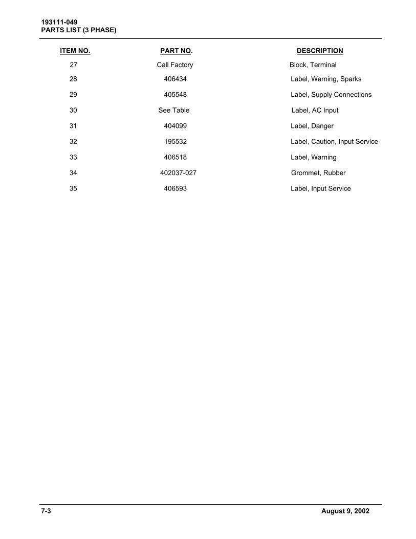
ITEM NO. PART NO. DESCRIPTION 27 Call Factory Block, Terminal 28 406434 Label, Warning, Sparks 29 405548 Label, Supply Connections 30 See Table Label, AC Input 31 404099 Label, Danger 32 195532 Label, Caution, Input Service 33 406518 Label, Warning 34 402037-027 Grommet, Rubber 35 406593 Label, Input Service

August 9, 2002 7-4
193111-049 PARTS LIST (3 PHASE)
3 PH
ASE
208/
240/
480
VOLT
U
NIT
S
AC
M
OD
EL
O
UTP
UT
T2
T3
D
IOD
E
CA
PS
IN
PU
T C
ON
TRO
L O
UTP
UT
NU
MB
ER
SP
EC
FU
SE
TR
AN
S
TRA
NS
C
ON
TAC
TOR
(4
Req
uire
d)
/TR
AN
S
LAB
EL
TRA
NS
C
AB
LE
12-5
10FR
100T
50
0522
-1
4090
23-4
19
5082
19
5083
40
6243
-1
1931
43-1
TR
Y-15
4-4
1914
57
4062
47-2
39
6143
-2
12-6
00FR
100T
50
0523
-1
4090
23-4
19
5091
19
5092
40
6243
-1
1931
43-1
TR
Y-15
4-4
1914
57
4062
47-2
39
6143
-2
12-7
50FR
100T
50
0524
-1
4090
23-5
19
5100
19
5101
40
6243
-1
4028
32-3
TR
Y-15
4-6
1914
57
4062
47-2
39
6143
-4
12-8
80FR
100T
50
0525
-1
4090
23-6
19
5109
19
5110
40
6243
-1
4028
32-3
TR
Y-15
4-4
1914
57
4062
47-2
39
6143
-4
TR
Y-15
4-1
12
-105
0FR
100T
50
0526
-1
4090
23-7
19
5118
19
5119
40
6243
-1
4028
32-3
TR
Y-15
4-4
1914
57
4062
47-2
39
6143
-5
TR
Y-15
4-1
18
-510
FR10
0T
5005
27-1
40
9023
-4
1951
27
1951
28
4062
43-1
19
3143
-1
TRY-
154-
4 19
1457
40
6247
-2
3961
43-2
18
-600
FR10
0T
5005
28-1
40
9023
-4
1951
36
1951
37
4062
43-1
19
3143
-1
TRY-
154-
4 19
1457
40
6247
-2
3961
43-2
TRY-
154-
2
18-7
50FR
100T
50
0529
-1
4090
23-5
19
5145
19
5146
40
6243
-1
4028
32-3
TR
Y-15
4-4
1914
57
4062
47-2
39
6143
-4
TR
Y-15
4-2
18
-880
FR10
0T
5005
30-1
40
9023
-6
1951
54
1951
55
4062
43-1
40
2832
-3
TRY-
154-
6 19
1457
40
6247
-2
3961
43-4
18
-965
FR10
0T
5005
31-1
40
9023
-7
1951
63
1951
64
4062
44-1
40
2832
-3
TRY-
154-
4 19
1457
40
6247
-2
3961
43-5
TRY
154-
2
18-1
050F
R10
0T
5005
32-1
40
9023
-7
1951
72
1951
73
4062
44-1
40
2832
-3
TRY-
154-
4 19
1457
40
6247
-2
3961
43-5
TRY-
154-
2
18-1
100F
R10
0T
5005
33-1
40
9023
-8
1951
81
1951
82
4062
44-1
40
2832
-3
TRY-
154-
4 19
1457
40
6247
-2
3961
43-5
TRY-
154-
2
18-1
200F
R10
0T
5005
34-1
40
9023
-8
1951
90
1951
91
4062
44-1
40
2832
-3
TRY-
154-
4 19
1457
40
6247
-2
3961
43-5
TRY-
154-
3
24-4
50FR
100T
50
0535
-1
4090
23-4
19
5199
19
5200
40
6243
-1
1931
43-1
TR
Y-15
4-6
1914
57
4062
47-2
39
6143
-2
24-6
00FR
100T
50
0536
-1
4090
23-4
19
5208
19
5209
40
6243
-1
1931
43-1
TR
Y-15
4-6
1914
57
4062
47-2
39
6143
-2
24-7
50FR
100T
50
0537
-1
4090
23-5
19
5217
19
5218
40
6244
-1
4028
32-3
TR
Y-15
4-4
1914
57
4062
47-2
39
6143
-4
TR
Y-15
4-2
24
-880
FR10
0T
5005
38-1
40
9023
-6
1952
26
1952
27
4062
44-1
40
2832
-3
TRY-
154-
6 19
1457
40
6247
-2
3961
43-4
24
-965
FR10
0T
5005
39-1
40
9023
-7
1952
35
1952
36
4062
44-1
40
2832
-3
TRY-
154-
6 19
1457
40
6247
-2
3961
43-5

193111-049 PARTS LIST (3 PHASE)
3 PH
ASE
480/
575
VOLT
U
NIT
S
AC
M
OD
EL
O
UTP
UT
T2
T3
D
IOD
E
CA
PS
IN
PU
T C
ON
TRO
L O
UTP
UT
NU
MB
ER
SP
EC
FU
SE
TR
AN
S
TRA
NS
C
ON
TAC
TOR
(4
Req
uire
d)
/TR
AN
S
LAB
EL
TRA
NS
C
AB
LE
12-5
10FR
100T
50
0522
-2
4090
23-4
19
5086
19
5087
40
6243
-1
1931
43-1
TR
Y-15
4-4
1912
52
4062
47-4
39
6143
-2
12-6
00FR
100T
50
0523
-2
4090
23-4
19
5095
19
5096
40
6243
-1
1931
43-1
TR
Y-15
4-4
1912
52
4062
47-4
39
6143
-2
12-7
50FR
100T
50
0524
-2
4090
23-5
19
5104
19
5105
40
6243
-1
4028
32-3
TR
Y-15
4-6
1912
52
4062
47-4
39
6143
-4
12-8
80FR
100T
50
0525
-2
4090
23-6
19
5113
19
5114
40
6243
-1
4028
32-3
TR
Y-15
4-4
1912
52
4062
47-4
39
6143
-4
TR
Y-15
4-1
12
-105
0FR
100T
50
0526
-2
4090
23-7
19
5122
19
5123
40
6243
-1
4028
32-3
TR
Y-15
4-4
1912
52
4062
47-4
39
6143
-5
TR
Y-15
4-1
18
-510
FR10
0T
5005
27-2
40
9023
-4
1951
31
1951
32
4062
43-1
19
3143
-1
TRY-
154-
4 19
1252
40
6247
-4
3961
43-2
18
-600
FR10
0T
5005
28-2
40
9023
-4
1951
40
1951
41
4062
43-1
19
3143
-1
TRY-
154-
4 19
1252
40
6247
-4
3961
43-2
TRY-
154-
2
18-7
50FR
100T
50
0529
-2
4090
23-5
19
5149
19
5150
40
6243
-1
4028
32-3
TR
Y-15
4-4
1912
52
4062
47-4
39
6143
-4
TR
Y-15
4-2
18
-880
FR10
0T
5005
30-2
40
9023
-6
1951
58
1951
59
4062
43-1
40
2832
-3
TRY-
154-
6 19
1252
40
6247
-4
3961
43-4
18
-965
FR10
0T
5005
31-2
40
9023
-7
1951
67
1951
68
4062
43-1
40
2832
-3
TRY-
154-
4 19
1252
40
6247
-4
3961
43-5
TRY
154-
2
18-1
050F
R10
0T
5005
32-2
40
9023
-7
1951
76
1951
77
4062
43-1
40
2832
-3
TRY-
154-
4 19
1252
40
6247
-4
3961
43-5
TRY-
154-
2
18-1
100F
R10
0T
5005
33-2
40
9023
-8
1951
85
1951
86
4062
43-1
40
2832
-3
TRY-
154-
4 19
1252
40
6247
-4
3961
43-5
TRY-
154-
2
18-1
200F
R10
0T
5005
34-2
40
9023
-8
1951
94
1951
95
4062
43-1
40
2832
-3
TRY-
154-
4 19
1252
40
6247
-4
3961
43-5
TRY-
154-
3
24-4
50FR
100T
50
0535
-2
4090
23-4
19
5203
19
5204
40
6243
-1
1931
43-1
TR
Y-15
4-6
1912
52
4062
47-4
39
6143
-2
24-6
00FR
100T
50
0536
-1
4090
23-4
19
5212
19
5213
40
6243
-1
1931
43-1
TR
Y-15
4-6
1912
52
4062
47-4
39
6143
-2
24-7
50FR
100T
50
0537
-1
4090
23-5
19
5221
19
5222
40
6243
-1
4028
32-3
TR
Y-15
4-4
1912
52
4062
47-4
39
6143
-4
TR
Y-15
4-2
24
-880
FR10
0T
5005
38-1
40
9023
-6
1952
30
1952
31
4062
43-1
40
2832
-3
TRY-
154-
6 19
1252
40
6247
-4
3961
43-4
24
-965
FR10
0T
5005
39-1
40
9023
-7
1952
39
1952
40
4062
43-1
40
2832
-3
TRY-
154-
6 19
1252
40
6247
-4
3961
43-5
7-5 August 9, 2002

DIAGRAMS - 3 PHASE
August 9, 2002
193111-049 DIAGRAMS (3 PHASE)
MODEL NO.
INFORMATION
DIAGRAM OUTPUT SCHEMATIC 208/240/480 VOLTS
DIAGRAM OUTPUT SCHEMATIC
480/575V
DIMENSIONAL
OUTLINE
3 PHASE (2 TRANSFORMERS) 195432 195542
See model number description inside front cover.
195541

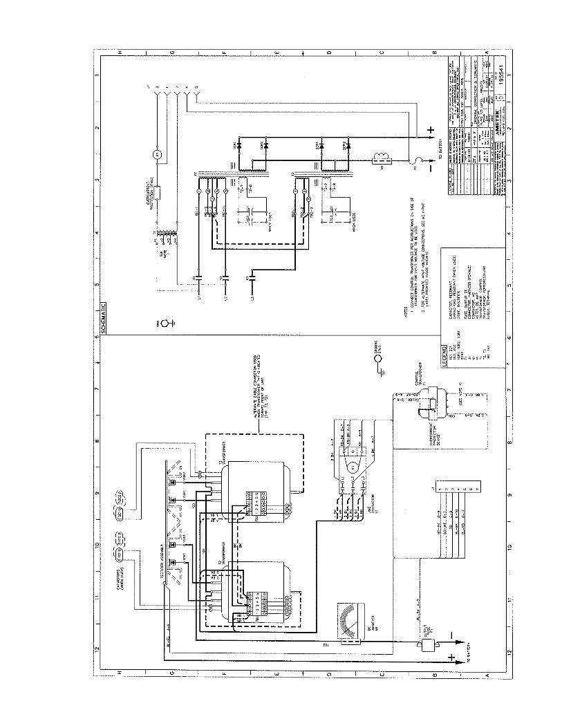


Figure 8-1 SINGLE PHASE
193111-049 PARTS LIST (1 PHASE)
8-1 December 10, 2008

ITEM NO. PART NO. DESCRIPTION 1 191578 Panel, Rear 2 191580 Panel, Side, Right 3 191580 Panel, Side, Left 4 191581 Top 5 192983 Panel, Front 6 See Table Meter DC Amps 7 191574 Base 8 195251 Overlay, Charger 9 195532 Label, Caution AC Input 10 195529-001 Board, PC, Ay 11 357205-060 Jumper, Orange (2 Required) 12 357205-061 Jumper, White (2 Required) 13 See Table Capacitor, AC Oil 14 TRY174-003 Bracket, Capacitor 15 See Table Transformer, Control 16 406434 Label, Warning, Input 17 See Table Transformer, T2 18 Contact Factory Terminal Block 19 392458 Bus Bar (2 Required) 20 See Table Fuse, Output. 21 See Table Contactor, Line 22 See Table Rectifier Ay 23 378234-013 Cover, Outer Neoprene 24 W10080-005 Connector, Strain Relief 25 See Table Cable, Output 26 See Table Label, AC Input
193111-049 PARTS LIST (1 PHASE)
December 10, 2008 8-2

ITEM NO. PART NO. DESCRIPTION 27 404099 Label, Danger 28 406518 Label, Warning 29 195531 Label, DC Fuse 30 406593 Label, AC Input 31 405548 Label, Frame Ground 32 406748 Label, AC Line Connections, 120V 33 195856 Harness, Wire (Not Shown)
8-3 December 10, 2008
193111-049 PARTS LIST (1 PHASE)
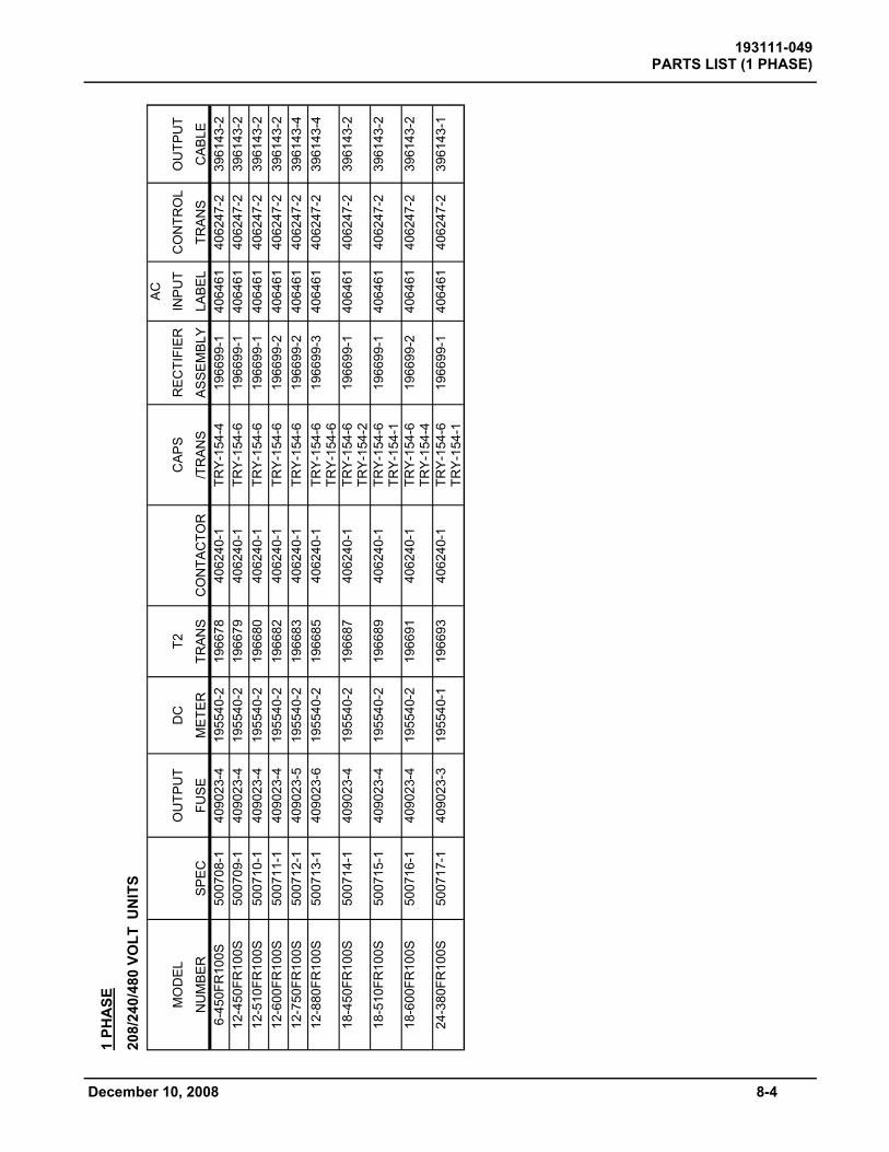
1 PH
ASE
208/
240/
480
VOLT
UN
ITS
A
C
MO
DE
L
OU
TPU
T D
C
T2
C
AP
S
RE
CTI
FIE
R
INP
UT
CO
NTR
OL
OU
TPU
T
NU
MB
ER
S
PE
C
FUS
E
ME
TER
TR
AN
S
CO
NTA
CTO
R
/TR
ANS
AS
SE
MB
LY
LAB
EL
TRA
NS
C
AB
LE
6-45
0FR
100S
50
0708
-1
4090
23-4
19
5540
-2
1966
78
4062
40-1
TR
Y-15
4-4
1966
99-1
40
6461
40
6247
-2
3961
43-2
12
-450
FR10
0S
5007
09-1
40
9023
-4
1955
40-2
19
6679
40
6240
-1
TRY-
154-
6 19
6699
-1
4064
61
4062
47-2
39
6143
-2
12-5
10FR
100S
50
0710
-1
4090
23-4
19
5540
-2
1966
80
4062
40-1
TR
Y-15
4-6
1966
99-1
40
6461
40
6247
-2
3961
43-2
12
-600
FR10
0S
5007
11-1
40
9023
-4
1955
40-2
19
6682
40
6240
-1
TRY-
154-
6 19
6699
-2
4064
61
4062
47-2
39
6143
-2
12-7
50FR
100S
50
0712
-1
4090
23-5
19
5540
-2
1966
83
4062
40-1
TR
Y-15
4-6
1966
99-2
40
6461
40
6247
-2
3961
43-4
12
-880
FR10
0S
5007
13-1
40
9023
-6
1955
40-2
19
6685
40
6240
-1
TRY-
154-
6 TR
Y-15
4-6
1966
99-3
4064
61
4062
47-2
39
6143
-4
18-4
50FR
100S
50
0714
-1
4090
23-4
19
5540
-2
1966
87
4062
40-1
TR
Y-15
4-6
TRY-
154-
2 19
6699
-1
4064
61
4062
47-2
39
6143
-2
18-5
10FR
100S
50
0715
-1
4090
23-4
19
5540
-2
1966
89
4062
40-1
TR
Y-15
4-6
TRY-
154-
1 19
6699
-1
40
6461
40
6247
-2
3961
43-2
18-6
00FR
100S
50
0716
-1
4090
23-4
19
5540
-2
1966
91
4062
40-1
TR
Y-15
4-6
TRY-
154-
4 19
6699
-2
4064
61
4062
47-2
39
6143
-2
24-3
80FR
100S
50
0717
-1
4090
23-3
19
5540
-1
1966
93
4062
40-1
TR
Y-15
4-6
TRY-
154-
1 19
6699
-1
40
6461
40
6247
-2
3961
43-1
December 10, 2008 8-4
193111-049 PARTS LIST (1 PHASE)
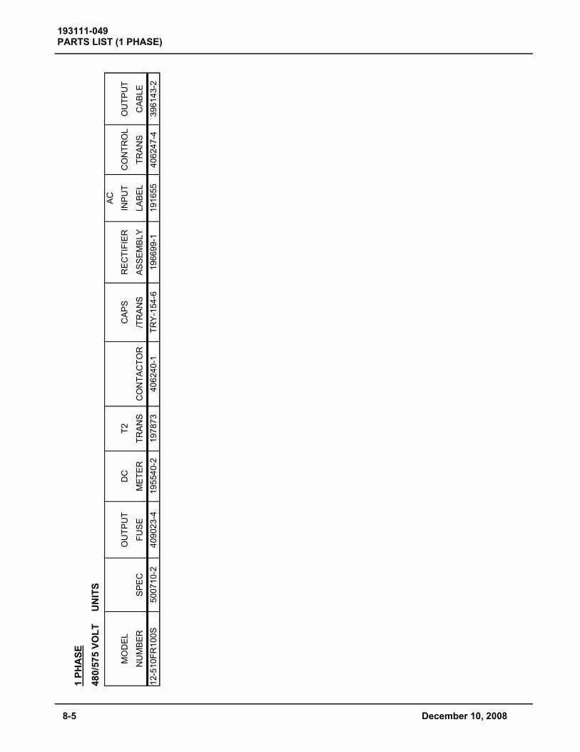
1 PH
ASE
480/
575
VOLT
U
NIT
S
AC
MO
DE
L
OU
TPU
T D
C
T2
C
AP
S
RE
CTI
FIE
R
INP
UT
CO
NTR
OL
OU
TPU
T
NU
MB
ER
S
PE
C
FUS
E
ME
TER
TR
AN
S
CO
NTA
CTO
R
/TR
ANS
AS
SE
MB
LY
LAB
EL
TRA
NS
C
AB
LE
12-5
10FR
100S
50
0710
-2
4090
23-4
19
5540
-2
1978
73
4062
40-1
TR
Y-15
4-6
1966
99-1
19
1655
40
6247
-4
3961
43-2
193111-049 PARTS LIST (1 PHASE)
8-5 December 10, 2008

MODEL NO.
INFORMATION
DIAGRAM OUTPUT SCHEMATIC 208/240/480 VOLTS
DIAGRAM OUTPUT SCHEMATIC
480/575V
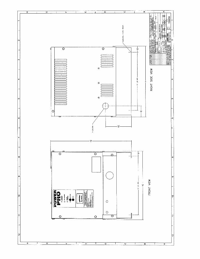
DIMENSIONAL
OUTLINE
1 PHASE (1 TRANSFORMER) 195433 195859
See model number description inside front cover.
197871
DIAGRAMS - 1 PHASE
193111-049 DIAGRAMS (1 PHASE)
December 10, 2008


WARRANTY
AMETEK/PRESTOLITE POWER “POWER PRO” BATTERY CHARGERS AMETEK/Prestolite Power (hereinafter called “Prestolite”) warrants that each new and unused Power Pro Battery Charger manufactured and supplied by it is of good workmanship and is free from any inherent mechanical defects, provided that (1) the product is installed and operated in accordance with generally accepted industrial standards and in accordance with the printed instructions of Prestolite, (2) the product is used under normal conditions for which designed, (3) the product is not subjected to misuse, negligence or accident, and (4) the product receives proper care, protection and maintenance under supervision of competent personnel. This warranty is subject to the following provisions: 1.PRODUCTS AND PARTS WARRANTED. Subject to the exceptions listed below each Power Pro Battery Charger is warranted for a period of one (1) year from the date of its shipment by Prestolite, provided the charger is used in accordance with Prestolite’s published performance rating for the unit involved. The exceptions to this warranty are as follows:
a) Power transformers and diodes on unit(s) are warranted for ten (10) years after Prestolite’s shipment of the unit(s) of which they are a part, provided, however, that during the last nine (9) years of this ten (10) year period the warranty covers parts
replacement only-no labor or other services are provided by Prestolite, nor shall Prestolite be obligated to reimburse the owner or any other person for any work performed. b) Primary switch contacts, fuses, bulbs, and filters are not warranted unless found to be defective prior to use.
2.COMMENCEMENT OF WARRANTY TIME PERIODS. The warranty periods indicated in the Warranty Schedule shall commence on the date of shipment by Prestolite. 3.PERSONS COVERED BY WARRANTY. This warranty is extended by Prestolite only to the purchaser of new equipment from Prestolite or one of its authorized distributors. The products purchased under this agreement shall be used exclusively by the buyer and its employees and by no other persons, and therefore there shall be no third party beneficiary to this warranty. 4.LIMITATION OF REMEDY. The existence of claimed defects in any product covered by this warranty is subject to Prestolite’s factory inspection and judgment. Prestolite’s liability is limited to repair of any defects found by Prestolite to exist or, at Prestolite’s option, the replacement of the defective product. F.O.B. factory after the defective product has been returned by the purchaser at its expense to Prestolite’s shipping place. Replacement parts will be warranted for the remainder of the original Power Pro Battery Charger Warranty or for a period of ninety (90) days, whichever is greater. PRESTOLITE and its authorized distributors or dealers shall not be liable for direct or indirect, special or consequential damages in excess of such repair or replacement. In no event shall the purchaser be entitled to recover for contingent expenses resulting from, but not limited to, telephone calls, telegrams, travel expenses, lodging, duties and taxes, labor, rental or replacement equipment, loss of business or profits or other commercial losses. 5.USE OF DEFECTIVE PRODUCT. Continued use of a Power Pro Battery Charger after discovery of a defect VOIDS ALL WARRANTIES. 6.ALTERED EQUIPMENT. Except as authorized in writing, the warranty specified does not cover any equipment that has been altered by any party other that Prestolite. EXCEPT AS STATED ABOVE, ALL OTHER WARRANTIES AND CONDITIONS, EITHER EXPRESSED OR IMPLIED, INCLUDING IMPLIED WARRANTIES OF MERCHANTABILITY AND FITNESS FOR A PARTICULAR PURPOSE, ARE EXCLUDED AND BUYER ASSUMES ALL RISK AND LIABILITY RESULTING FROM USE OF THE GOODS. AMETEK/PRESTOLITE POWER NEITHER ASSUMES NOR AUTHORIZES ANY PERSONS TO ASSUME FOR AMETEK/PRESTOLITE POWER ANY OTHER LIABILITY IN CONNECTION WITH THE SALE OR USE OF THE GOODS SOLD, AND THERE ARE NO ORAL AGREEMENTS OR WARRANTIES COLLATERAL TO OR AFFECTING THIS WRITTEN WARRANTY.
WARNING At all times, safety must be considered an important factor in the installation, servicing, and operation of the product, and skilled, qualified technical assistance should be utilized. AMETEK/PRESTOLITE POWER TROY, OHIO, U.S.A. Data Sheet: 1150 Index: 080102 Replaces: Original