Owner's Manual… · 1 Owner's Manual Overview Introduction Thank you for choosing the Vocalist ®...
83
Owner's Manual
Transcript of Owner's Manual… · 1 Owner's Manual Overview Introduction Thank you for choosing the Vocalist ®...
Owner'sManual
IMPORTANT SAFETY INSTRUCTIONS
WARNING FOR YOUR PROTECTIONREAD THE FOLLOWING:
KEEP THESE INSTRUCTIONS
HEED ALL WARNINGS
FOLLOW ALL INSTRUCTIONS
THE APPARATUS SHALL NOT BE EXPOSED TO DRIPPING OR SPLASHING LIQUID AND NO OBJECT FILLED WITH LIQUID, SUCH AS VASES, SHALL BE PLACED ON THE APPARATUS
CLEAN ONLY WITH A DRY CLOTH.
FOR INDOOR USE ONLY.
DO NOT BLOCK ANY OF THE VENTILATION OPENINGS. INSTALL IN ACCORDANCE WITH THE MANUFACTURER’S INSTRUCTIONS.
DO NOT INSTALL NEAR ANY HEAT SOURCES SUCH AS RADIATORS, HEAT REGISTERS, STOVES, OR OTHER APPARATUS (INCLUDING AMPLIFIERS) THAT PRODUCE HEAT.
ONLY USE ATTACHMENTS/ACCESSORIES SPECIFIED BY THE MANUFACTURER.
UNPLUG THIS APPARATUS DURING LIGHTNING STORMS OR WHEN UNUSED FOR LONG PERIODS OF TIME.
Do not defeat the safety purpose of the polarized or grounding-type plug. A polarized plug has two blades with one wider than the other. A grounding type plug has two blades and a third grounding prong. The wide blade or third prong are provided for your safety. If the provided plug does not fit your outlet, consult an electrician for replacement of the obsolete outlet.
Protect the power cord from being walked on or pinched particularly at plugs, convenience receptacles, and the point where they exit from the apparatus.
Refer all servicing to to qualified service personnel. Servicing is required when the apparatus has been damaged in any way, such as power-supply cord or plug is damaged, liquid has been spilled or objects have fallen into the apparatus, the apparatus has been exposed to rain or moisture, does not operate normally, or has been dropped.
MAINS DISCONNECT: The plug shall remain readily operable. For rack-mount or installation where plug is not accessible, an all-pole mains switch with a contact separation of at least 3 mm in each pole shall be incorporated into the electrical installation of the rack or building.
If connected to 240V supply, a suitable CSA/UL certified power cord shall be used for this supply.
ELECTROMAGNETICCOMPATIBILITY
This device complies with part 15 of the FCC Rules and
the Product Specifications noted on the Declaration of
Conformity. Operation is subject to the following two
conditions:
• this device may not cause harmful interference, and
• this device must accept any interference received,
including interference that may cause undesired
operation.
Operation of this unit within significant electromagnetic
fields should be avoided.
• use only shielded interconnecting cables.
The symbols shown above are internationally accepted symbols that warn of potential hazards with electrical products. The lightning flash with arrowpoint in an equilateral triangle means that there are dangerous voltages present within the unit. The exclamation point in an equilateral triangle indicates that it is necessary for the user to refer to the owner’s manual.
These symbols warn that there are no user serviceable parts inside the unit. Do not open the unit. Do not attempt to service the unit yourself. Refer all servicing to qualified personnel. Opening the chassis for any reason will void the manufacturer’s warranty. Do not get the unit wet. If liquid is spilled on the unit, shut it off immediately and take it to a dealer for service. Disconnect the unit during storms to prevent damage.
The following is indicative of low altitude use; do not use this product above 2000m.
Pour la version française de ce manuel aller à digitech.com

IMPORTANT SAFETY INSTRUCTIONS
If you want to dispose this product, do not mix it with general household waste. There is a separate collection system for used electronic products in accordance with legislation that requires proper treatment, recovery and recycling.
Private household in the 25 member states of the EU, in Switzerland and Norway may return their used electronic products free of charge to designated collection facilities or to a retailer (if you purchase a similar new one).
For Countries not mentioned above, please contact your local authorities for a correct method of disposal.
By doing so you will ensure that your disposed product undergoes the necessary treatment, recovery and recycling and thus prevent potential negative effects on the environment and human health.
DECLARATION OF CONFORMITY
Manufacturer’s Name: DigiTech Manufacturer’s Address: 10653 South River Front Parkway Suite 300 South Jordan, Utah 84095, USA
declares that the product:
Product name: Vocalist Live Harmony Product option: all (requires Class II power adapter that conforms to the requirements of EN60065, EN60742, or equivalent.)
conforms to the following Product Specifications:
Safety: IEC 60065 -01+Amd 1 EMC: EN 55022:2006 EN 55024:1998 FCC Part 15
Supplementary Information:
The product herewith complies with the requirements of the:Low Voltage Directive 2006/95/ECEMC Directive 2004/108/EC.RoHS Directive 2002/95/ECWEEE Directive 2002/96/EC EC Regulation 278/2009
With regard to Directive 2005/32/EC and EC Regulation 1275/2008 of 17 December 2008, this product is designed, produced, and classified as Professional Audio Equipment and thus is exempt from this Directive.
Rex C. Reed Director, Engineering Signal Processing10653 South River Front ParkwaySuite 300South Jordan, Utah 84095, USA Date: March 7, 2013
European Contact: Your local DigiTech Sales and Service Office or
Harman Signal Processing10653 South River Front ParkwaySuite 300South Jordan, Utah 84095, USAPh: (801) 566-8800Fax: (801) 568-7583
Pour la version française de ce manuel aller à digitech.com

Owner's Manual
Warranty & Registration We at DigiTech® are very proud of our products and back-up each one we sell with the following warranty:
1. Please register online at www.digitech.com within ten days of purchase to validate this warranty. This warranty is valid only in the United States.
2. DigiTech warrants this product, when purchased new from an authorized U.S. DigiTech dealer and used solely within the U.S., to be free from defects in materials and workmanship under normal use and service. This warranty is valid to the original purchaser only and is non-transferable.
3. DigiTech liability under this warranty is limited to repairing or replacing defective materials that show evidence of defect, provided the product is returned to DigiTech WITH RETURN AUTHORIZATION, where all parts and labor will be covered up to a period of one year. A Return Authorization number may be obtained from DigiTech by telephone. The company shall not be liable for any consequential damage as a result of the product’s use in any circuit or assembly.
4. Proof-of-purchase is considered to be the responsibility of the consumer. A copy of the original purchase receipt must be provided for any warranty service.
5. DigiTech reserves the right to make changes in design, or make additions to, or improvements upon this product without incurring any obligation to install the same on products previously manufactured.
6. The consumer forfeits the benefits of this warranty if the product’s main assembly is opened and tampered with by anyone other than a certified DigiTech technician or, if the product is used with AC voltages outside of the range suggested by the manufacturer.
7. The foregoing is in lieu of all other warranties, expressed or implied, and DigiTech neither assumes nor authorizes any person to assume any obligation or liability in connection with the sale of this product. In no event shall DigiTech or its dealers be liable for special or consequential damages or from any delay in the performance of this warranty due to causes beyond their control.
NOTE: The information contained in this manual is subject to change at any time without notification. Some information contained in this manual may also be inaccurate due to undocumented changes in the product since this version of the manual was completed. The information contained in this version of the owner’s manual supersedes all previous versions.
Service/Contact Information If you require technical support, contact DigiTech Technical Support. Be prepared to accurately describe the problem. Know the serial number of your device – this is printed on a sticker attached to the chassis.
Before you return a product to the factory for service, we recommend you refer to this manual. Make sure you have correctly followed installation steps and operation procedures. For further technical assistance or service, please visit our support page at digitech.com. If you need to return a product to the factory for service, you MUST first contact Technical Support to obtain a Return Authorization Number.
No returned products will be accepted at the factory without a Return Authorization Number.
Please refer to the warranty information, which extends to the first end-user. After expiration of the warranty, a reasonable charge will be made for parts, labor, and packing if you choose to use the factory service facility. In all cases, you are responsible for transportation charges to the factory. DigiTech will pay return shipping if the unit is still under warranty.
Use the original packing material if it is available. Mark the package with the name of the shipper and with these words in red: DELICATE INSTRUMENT, FRAGILE! Insure the package properly. Ship prepaid, not collect. Do not ship parcel post.
Owner's Manual
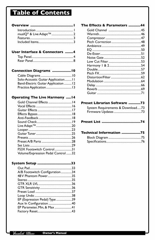
Table of Contents
Overview ...........................................1Introduction ................................................1musIQ® & Live Adapt™ ............................2Features ........................................................3Included Items.............................................3
User Interface & Connectors ........4Top Panel ......................................................4Rear Panel ....................................................8
Connection Diagrams ...................10Cable Diagrams ........................................10Solo-Acoustic Guitar Application .........11Band-Electric Guitar Application ..........12Practice Application .................................13
Operating The Live Harmony .....14Gold Channel Effects ..............................14Vocal Effects ..............................................16Guitar Effects ............................................17Effects Bypass ............................................18Anti-Feedback ...........................................18Sound Check .............................................19Live Adapt™ ..............................................20Looper ........................................................23Guitar Tuner ..............................................25Presets ........................................................26Preset A/B Parts .......................................28Set Lists ......................................................29FS3X Footswitch Control ......................31Volume/Expression Pedal Control .......32
System Setup ..................................33Out Pad ......................................................33A/B Footswitch Configuration ..............3448 V Phantom Power ...............................35Stereo .........................................................35GTR XLR LVL ...........................................36GTR Sensitivity .........................................36Preset Load ...............................................37Loop Undo ................................................38EP (Expression Pedal) Type ....................39Aux In Configuration ..............................40EP Parameter, Min, & Max ......................41Factory Reset ............................................43
The Effects & Parameters ............44Gold Channel ..........................................45Warmth ......................................................46Compressor ..............................................47Pitch Correction ......................................48Ambience ...................................................49EQ ...............................................................50De-Esser .....................................................51Noise Gate ................................................52Low Cut Filter ..........................................53Harmony 1 & 2 .........................................54Double ........................................................57Pitch FX ......................................................59Distortion/Filter .......................................62Modulation ................................................64Delay ...........................................................66Reverb ........................................................69Guitar .........................................................71
Preset Librarian Software ............73System Requirements & Download .....73Firmware Updates ...................................73
Preset List .......................................74
Technical Information ...................75Block Diagram ..........................................75Specifications .............................................76

Owner's Manual1
Overview IntroductionThank you for choosing the Vocalist® Live Harmony by DigiTech®. The Live Harmony is a feature-packed vocal harmony and effects processor. It incorporates a high-quality mic preamp, two-part harmony generation, studio-grade vocal effects, pitch correction, dbx® Advanced Feedback Suppression, the latest musIQ® technology with Live Adapt™, a built-in phrase looper, and much, much more. This combination of features and sound quality provide professional, studio quality effects and intelligent harmony generation for vocalists performing live.
The Live Harmony begins with a global channel strip processing chain, referred to as the “Gold Channel” effects. This global set of 8 effects is used across all presets, providing the sonic foundation for your vocal sound. The Gold Channel effects comprise: Warmth, Compression, Pitch Correction, Lexicon® Ambience, 3-Band EQ, De-Essing, Noise Gating, and Low Cut.
The harmony section offers full control over two voices of next-generation harmony, making it possible to fine-tune the level, gender, pan, and harmony type of each voice. In addition, the Vocalist Live Harmony includes the most important effects for enhancing a vocal performance, including: Lexicon Reverbs, Delays, Doubling, as well as various Pitch, Filter/Distortion, and Modulation effects. All effects are easily enabled and edited thanks to dedicated buttons, a full graphics LCD display, and four soft knobs.
One of the most significant features of the Live Harmony is Live Adapt™. Live Adapt uses the internal analysis microphone or Aux In jack to provide automatic, real-time effect tempo adjustment, smart gating of non-vocal signals (internal mic only), and intelligent pitch and harmony generation using the detected key of the music.
For the guitarist who wants to travel light, the Vocalist Live Harmony includes a guitar input for mixing your guitar signal to the Live Harmony's outputs and/or for generating the harmony and pitch key. You can even apply built-in guitar effects, including: flanger, vibrato, chorus, reverb and more. Or just use the guitar input for vocal harmony and pitch key generation and use the Guitar Thru jack to send your guitar signal out to your own personal guitar rig.
Three rugged footswitches provide preset A/B part selection, preset navigation, global effects bypass, and hands-free control of the built-in phrase looper.
The rear panel boasts all the necessary connections for the performing singer, including a USB port for firmware updates and preset management using the free Vocalist Live Librarian software for Mac® and PC.
With a quick-access user interface, two-part harmony generation, a plethora of studio-quality effects, dbx Advanced Feedback Suppression, and state-of-the-art processing technologies, the Live Harmony gives you the tools you need to take center stage with confidence.
Owner's Manual 2
musIQ® & Live Adapt™musIQ is a revolutionary chord detection technology that analyzes the audio in real time and determines what notes are being played, while the musIQ harmony engine is capable of interpreting this note data along with the pitch of the singer to determine the most musically correct harmony notes to generate.
The Live Harmony’s Live Adapt feature uses musIQ to provide even further functionality by adapting the noise gate threshold, the pitch correction and pitch effect key, and the modulation and delay effect tempo settings. With musIQ & Live Adapt, the Live Harmony can adapt to changes in your music, creating a truly dynamic performance.
Owner's Manual3
Features
• Microphone Preamp w/+48V Phantom Power
• Channel Strip Style Processing w/Pitch Correction, Compression, Lexicon® Ambience, & More
• High-Quality, Customizable Two-Part Vocal Harmony Generation
• Studio-Grade Vocal Effects, Including: Lexicon® Reverbs, Delays, Doubling, Pitch Shifting, Modulation, & Distortion/Filter Effects
• dbx® Advanced Feedback Suppression
• Latest musIQ® Technology & Internal Analysis Mic
• Live Adapt™ for Real-Time Adaptive Control of Noise Gating, Pitch/Harmony Key, & Effect Tempo
• Sound Check for Easy Auditioning & Setup of Effects
• Guitar Input for Classic MusIQ Harmony & Pitch Generation & Optionally Mixing the Guitar Signal to the Live Harmony's Outputs
• Built-In Guitar Tuner
• Selectable Guitar Effect + Reverb
• Guitar Thru Jack for Sending the Unprocessed Guitar Signal to Your Own Guitar Rig
• 70 Second Mono Phrase Looper (35 Seconds w/Undo)
• 99 User & 99 Factory Presets
• 24-bit/44.1kHz Audio Quality
• Easy-To-Read Backlit LCD Display
• USB Port for Firmware Updates & Preset Management
• Vocalist Live Librarian Preset Management Software for Mac & PC
Included Items
• Vocalist Live Harmony Processor
• Power Supply
• Quick Start
The utmost care was taken while manufacturing your Live Harmony. Everything should be included and in perfect working order. If anything is missing or damaged, please contact your dealer at once.

Owner's Manual 4
User Interface & Connectors Top Panel
Harmony 2
Harmony LevelVoice 1 Voice 2
Key/Scale
18
619
7
8
1214
910
17
1615
11
13
1 32 54
1. Gold Channel Button Pressing this button turns the Gold Channel effects on and off; the effects are on when the button is lit. The Gold Channel effects provide the sonic foundation for your vocal sound and are used as the front end for all presets. Press and hold this button to edit Gold Channel settings using the DATA encoder [7] and Edit knobs [11]. Select one of the Gold Channel "types" (several pre-configured Gold Channel setups) to get started then modify the settings to taste (see "Gold Channel Effects" on page 14).
2. Harmony 1 & 2 Buttons These buttons turn each Harmony voice on or off when pressed. When each button is lit, the corresponding voice is enabled. Press and hold each of these buttons to edit the corresponding voice’s settings.

Owner's Manual5
3. Vocal Effect Buttons These buttons turn each corresponding Vocal effect on and off. Pressing and holding each button will enter the menu for editing the selected effect's settings (see "Vocal Effects" on page 16).
4. Live Adapt Mic This internal analysis microphone listens to the music being played in the room and adjusts settings in the Live Harmony automatically. It is used to adjust tempo for delay and modulation effects, adjust the key for generated harmonies and pitch correction/pitch effects, and adjust the noise gate threshold.
NOTE: Whenever the Aux In jack is connected to an audio source, it will be used for Live Adapt features instead of the internal microphone. When a connection is made to the Guitar In jack, the guitar signal will be used to determine the key/scale to follow for harmony generation and pitch effects based on the chord progression played. See "Live Adapt™" on page 20 for further information.
5. Guitar Effect Button This button turns the Guitar effects on and off. The Guitar effects give you two simultaneous effects to apply to your guitar signal: one allows you to select one of the available modulation effects and the other is a fixed reverb with a mix level control. Use these effects when connecting your guitar straight to the PA system through the Live Harmony's XLR or Line/Headphone outputs. The Guitar effects only process the signal present at the Guitar In jack. Pressing and holding this button will display the Guitar effect's settings in the LCD display, where they can be modified using the DATA encoder [7] and Edit knobs [11].
NOTE: The Guitar effect is passed to the XLR and 1/4" Line/Heaphone outputs only. It is not passed to the Guitar Thru jack, as this jack is intended to be used when connecting to your own personal outboard guitar effects and/or guitar amplifier (see "Guitar Effects" on page 17).
6. Vocal Signal LED This LED lights when the mic input signal is detected. This LED will light green when a signal is present, orange when approaching the A/D limiting point, and red when limiting occurs. Good practice is to set the microphone Input Gain knob so the Signal LED lights green regularly, lights orange occasionally, but never lights red.
NOTE: The Signal LED may also light red if the outputs clip due to the added gain from multiple enabled effects. If such a condition is encountered, simply lower the Input Gain knob until the Signal LED no longer indicates clipping.

Owner's Manual 6
7. DATA Encoder This encoder is used to navigate menus and edit certain parameters. Pressing this encoder selects different pages within the Gold Channel and System menus.
8. Store Button When pressed, this button initiates the preset store and copy functions. When a preset is edited, this button will light, indicating a change has been made to the preset’s stored settings.
9. System Button Pressing this button enters the System menu, where you can edit Live Harmony global system settings for configuring the Live Harmony for your application. Pressing the DATA Encoder [7] will navigate through the system menus.
10. Sound Check Button This button enables and disables the Sound Check feature. Sound Check lets you record a vocal loop which can then be used for auditioning and editing effect parameters (see "Sound Check" on page 19).
11. Edit Knobs These four knobs are used to edit the various effect and system parameters. They correspond to the available on-screen parameters as shown in the illustration to the right.
Harmony 2
Harmony LevelVoice 1 Voice 2
Key/Scale
WARMTH COMP CORRECT AMBNCE
20 15 50 35
Gold Channel TYPE
1/3 (Push)Standard
Edit 1Knob
Edit 2Knob
Edit 3Knob
Edit 4Knob
From the Preset screen, these knobs provide quick access to overall harmony level, voice 1 and voice 2 harmony intervals, and the key/scale setting.
Harmony 2
Harmony LevelVoice 1 Voice 2
Key/Scale
AMOUNT VOICING VOICING KEY
79 3D 5D Adapt
Harmony
musIQ Adapt
Edit 1Knob
Edit 2Knob
Edit 3Knob
Edit 4Knob
12. A/B Footswitch The Live Harmony lets you store two parts per preset: “A” and “B”. Vocal effects can be independently enabled or disabled in each part and the A/B footswitch toggles between these two parts. This feature can be helpful for applying effects within a song without having to switch between presets, such as enabling delays or distortion effects on certain words or vocal phrases. This A/B footswitch can be programmed in the System menu for toggle, momentary, or automatic operation (see "A/B Footswitch Configuration" on page 34 for more information).
13. UP Footswitch This footswitch selects the next preset up. Pressing and holding this footswitch for 1 second will bypass all Vocal effects (Gold Channel effects

Owner's Manual7
will not be affected). This "Vocal Effects Bypass" feature allows you to bypass all Vocal effects quickly, such as when talking to the audience between songs. Pressing and holding this footswitch for 2 seconds will access the built-in Guitar Tuner and mute the Live Harmony outputs while the tuner is active (see "Guitar Tuner" on page 25).
14. DOWN Footswitch This footswitch selects the next preset down. Pressing and holding this footswitch for 2 seconds enters Loop mode, where you can record loops using the built-in Phrase Looper (see "Looper" on page 23).
15. Anti-Feedback Button Pressing this button enables and disables dbx Advanced Feedback Suppression (AFS). When the button is lit, AFS is enabled (see "Anti-Feedback" on page 18).
16. Live Adapt Button Pressing this button globally enables and disables the Live Adapt feature. When the button is lit, Live Adapt is enabled. Pressing and holding this button enters the Live Adapt menu, where each of the separate Live Adapt functions can be enabled or disabled (see "Live Adapt™" on page 20).
17. Set List Button Pressing this button enters Set List mode. Set Lists create a sequenced list of up to twenty presets, making it easy to step through only the presets you want to use during a performance. Up to five Set Lists can be created. Pressing this button multiple times cycles through the available Set Lists. When the last Set List is selected, pressing this button again will exit Set List mode and return to Preset mode (see "Set Lists" on page 29).
18. LCD Display This easy-to-read backlit LCD display provides the visual feedback necessary for operating the Live Harmony.
19. Guitar Signal LED This LED lights when the guitar input signal is detected. This LED will light green when a signal is present, orange when approaching the A/D limiting point, and red when limiting occurs. Good practice is to set the GTR SENSITIVITY setting in the System menu so the Guitar LED lights green regularly, lights orange occasionally, but never lights red.

Owner's Manual 8
Rear Panel
12
4 5 63 7 8 9
11
10
1. Aux In Jack Connect a portable music player or the outputs of a mixer to this stereo 1/8" jack. Audio from an external device plugged into this jack can be used either for Live Adapt and musIQ analysis or the audio can be mixed in with the vocal signal at the line and XLR outputs.
NOTE: Whenever a device is connected to the Aux In jack, it will be used for Live Adapt features instead of the internal microphone. For harmony and pitch adaptive functions, priority is first given to the Guitar In jack if a connection is present. Second priority is given to the Aux In jack if a connection is present. If no connection is made to either the Guitar In or Aux In jacks, the internal mic will be used to gather the data for pitch and harmony generation. See "Live Adapt™" on page 20 for further information.
2. Input Gain Knob This knob controls the input gain of the Mic/Line In jack.
3. Mic/Line In Jack This combination jack accepts a microphone or line-level signal. Connect a microphone using an XLR connection to use the Live Harmony's internal mic preamp. +48 Volt phantom power can be enabled in the System menu for condenser microphones which require it. Connect using a 1/4" balanced TRS connection when connecting the line output of an external mic preamp to the Live Harmony.
4. Guitar In Jack Connect your guitar to this 1/4", unbalanced TS jack. The guitar signal will be used by musIQ for harmony generation instead of the internal analysis mic or Aux In jack. Use the GTR SENSITIVITY and GTR XLR LVL parameters found in the System menu to adjust your guitar input and output levels. See "GTR Sensitivity" on page 36 and "GTR XLR LVL" on page 36 for further information on these parameters.
Owner's Manual9
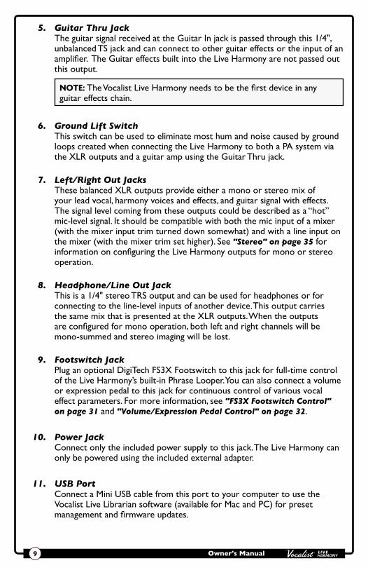
5. Guitar Thru Jack The guitar signal received at the Guitar In jack is passed through this 1/4", unbalanced TS jack and can connect to other guitar effects or the input of an amplifier. The Guitar effects built into the Live Harmony are not passed out this output.
NOTE: The Vocalist Live Harmony needs to be the first device in any guitar effects chain.
6. Ground Lift Switch This switch can be used to eliminate most hum and noise caused by ground loops created when connecting the Live Harmony to both a PA system via the XLR outputs and a guitar amp using the Guitar Thru jack.
7. Left/Right Out Jacks These balanced XLR outputs provide either a mono or stereo mix of your lead vocal, harmony voices and effects, and guitar signal with effects. The signal level coming from these outputs could be described as a “hot” mic-level signal. It should be compatible with both the mic input of a mixer (with the mixer input trim turned down somewhat) and with a line input on the mixer (with the mixer trim set higher). See "Stereo" on page 35 for information on configuring the Live Harmony outputs for mono or stereo operation.
8. Headphone/Line Out Jack This is a 1/4" stereo TRS output and can be used for headphones or for connecting to the line-level inputs of another device. This output carries the same mix that is presented at the XLR outputs. When the outputs are configured for mono operation, both left and right channels will be mono-summed and stereo imaging will be lost.
9. Footswitch Jack Plug an optional DigiTech FS3X Footswitch to this jack for full-time control of the Live Harmony’s built-in Phrase Looper. You can also connect a volume or expression pedal to this jack for continuous control of various vocal effect parameters. For more information, see "FS3X Footswitch Control" on page 31 and "Volume/Expression Pedal Control" on page 32.
10. Power Jack Connect only the included power supply to this jack. The Live Harmony can only be powered using the included external adapter.
11. USB Port Connect a Mini USB cable from this port to your computer to use the Vocalist Live Librarian software (available for Mac and PC) for preset management and firmware updates.

Owner's Manual 10
Connection Diagrams Cable Diagrams
Stereo Connection to Live Harmony Aux InUse a cable like the one shown below when connecting a stereo 1/4" feed to the Live Harmony's Aux In jack.
1/8" Stereo TRS to Dual 1/4" TS Cable
Left Channel (+)
Right Channel (+)
Ground
Left Channel
Right Channel
Ground
Ground
Left +
Left +
Right +
Right +
Ground
NOTE: You can also use the above cable when connecting a mono signal to the Aux In jack – such as when connecting an aux send or direct output from the mixing console. Simply connect only one of the 1/4" TS plugs to the desired output then leave the other disconnected.
Stereo Connection from Live Harmony Line OutUse a cable like the one shown below to connect the Live Harmony's 1/4" Headphone/Line Output to the 1/4" line inputs of another device.
1/4" Stereo TRS to Dual 1/4" TS Cable
Left Channel (+)
Right Channel (+)
Ground
Ground
Left +
Right +
Left Channel
Right Channel
Ground Left +
Right +Ground
NOTE: Connecting a mono TS cable to the 1/4" stereo Headphone/Line Output jack is not recommended. If you require a single mono feed from the 1/4" stereo Headphone/Line Output, it is recommended that you use a stereo cable as shown above and use only one of the TS plugs, leaving the other disconnected. You will then need to turn STEREO mode off in the System menu. See "Stereo" on page 35 for more information on changing the STEREO parameter.

Owner's Manual11
Solo-Acoustic Guitar ApplicationOften with an acoustic guitar it is convenient to provide a single output to the PA. The Vocalist Live Harmony allows you to mix the guitar with the vocals and send the guitar/vocal mix to the PA via the XLR Outputs. This allows you total control of your sound from on-stage. The Vocalist Live Harmony also provides the ability to add chorus and reverb to your guitar signal to fill out the sound. For a solo act it is no longer necessary to carry a mixer to the gig. To balance the guitar level with the vocals, adjust the GTR XLR LVL on page 2/6 in the System menu, see "GTR XLR LVL" on page 36 for further information.
Microphone Guitar
Mic or Line Input
Mic or Line Input
DigiTech FS3X Footswitch or Volume/Expression Pedal
HarmanPower Supply
Omit For Mono Optional
LEGEND
or
NOTE: By default the Live Harmony is configured for stereo operation. To configure the Live Harmony for mono operation you must turn off the STEREO option in the System menu, see "Stereo" on page 35 for further information.
Owner's Manual 12
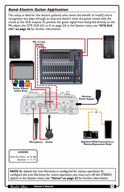
Band-Electric Guitar ApplicationThis setup is ideal for the electric guitarist who wants the benefit of musIQ chord recognition but plays through an amp and doesn't want the guitar mixed with the vocals at the XLR outputs. To prevent the guitar signal from being fed directly to the PA, adjust the GTR XLR LVL to 0 on page 2/6 in the System menu, see "GTR XLR LVL" on page 36 for further information.
Microphone Guitar
Mic or Line Input(s)
DigiTech FS3X Footswitch or Volume/Expression Pedal
Guitar Effects and/or Amp
HarmanPower Supply
Omit For Mono Optional
LEGEND
or
NOTE: By default the Live Harmony is configured for stereo operation. To configure the Live Harmony for mono operation you must turn off the STEREO option in the System menu, see "Stereo" on page 35 for further information.

Owner's Manual13
Practice ApplicationThis setup is ideal for practicing your skills, working on new material, or preparing for the gig. Connecting a portable music player lets you practice along with pre-recorded music. Connect a computer to backup your presets and set lists or graphically configure set lists for your next gig.
Microphone Guitar Headphones DigiTech FS3X Footswitch or Volume/Expression Pedal
Computer w/Vocalist Live Librarian Software
HarmanPower Supply
Portable Music Player
Optional
LEGEND
or
NOTE: In order to monitor the portable music player out of the Headphone/Line Out jack in this application, you must configure the Aux In jack for "Mix" operation, see "Aux In Configuration" on page 40 for further information.
NOTE: The headphone output level can be adjusted using the OUT PAD parameter in the System menu, see "Out Pad" on page 33 for more information.
Owner's Manual 14
Operating The Live Harmony This section of the manual describes how to navigate and use the various features of the Live Harmony.
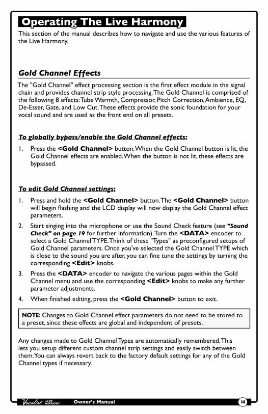
Gold Channel EffectsThe "Gold Channel" effect processing section is the first effect module in the signal chain and provides channel strip style processing. The Gold Channel is comprised of the following 8 effects: Tube Warmth, Compressor, Pitch Correction, Ambience, EQ, De-Esser, Gate, and Low Cut. These effects provide the sonic foundation for your vocal sound and are used as the front end on all presets.
To globally bypass/enable the Gold Channel effects:
1. Press the <Gold Channel> button. When the Gold Channel button is lit, the Gold Channel effects are enabled. When the button is not lit, these effects are bypassed.
To edit Gold Channel settings:
1. Press and hold the <Gold Channel> button. The <Gold Channel> button will begin flashing and the LCD display will now display the Gold Channel effect parameters.
2. Start singing into the microphone or use the Sound Check feature (see "Sound Check" on page 19 for further information). Turn the <DATA> encoder to select a Gold Channel TYPE. Think of these "Types" as preconfigured setups of Gold Channel parameters. Once you've selected the Gold Channel TYPE which is close to the sound you are after, you can fine tune the settings by turning the corresponding <Edit> knobs.
3. Press the <DATA> encoder to navigate the various pages within the Gold Channel menu and use the corresponding <Edit> knobs to make any further parameter adjustments.
4. When finished editing, press the <Gold Channel> button to exit.
NOTE: Changes to Gold Channel effect parameters do not need to be stored to a preset, since these effects are global and independent of presets.
Any changes made to Gold Channel Types are automatically remembered. This lets you setup different custom channel strip settings and easily switch between them. You can always revert back to the factory default settings for any of the Gold Channel types if necessary.

Owner's Manual15
To reset a Gold Channel Type back to its factory default settings:
1. Press and hold the <Gold Channel> button. The <Gold Channel> button will begin flashing and the LCD display will now display the Gold Channel effect parameters.
2. Turn the <DATA> encoder until you have selected the TYPE you wish to reset. If the selected TYPE has been modified from the default settings, the display will read "TYPE-MODIFIED".
3. Press the <DATA> encoder as many times as it takes to get to page 3 of 3 (3/3) in the Gold Channel menu. Once you are on page 3, you will see the RESET parameter in the bottom right-hand corner of the LCD display.
4. Turn the <Edit 4> knob to initiate the reset procedure.
5. A prompt will be displayed, allowing you to confirm or cancel the operation. Turn the <Edit 3> knob to select "Yes" and confirm the type reset procedure. Turn the <Edit 2> knob to select "No" and cancel the operation.

Owner's Manual 16
Vocal EffectsThe Vocal effects processing section comes after the Gold Channel effects and is comprised of the following 6 effect modules: Harmony 1, Harmony 2, Doubler, FX (pitch, modulation, and distortion/filter effects), Delay, and Reverb. Unlike the Gold Channel effects, Vocal effect settings are independently stored to each preset.
To bypass/enable a Vocal effect module:
1. Press the corresponding effect button (e.g., <Harmony 1>, <Double>, <FX>, etc.). When the effect button is lit, the corresponding effect is enabled. When the effect button is not lit, the corresponding effect is bypassed.
2. If you wish to store the Vocal effect’s enabled or bypassed state, press the <Store> button and perform the preset storing procedure. See "Presets" on page 26 for further information on storing user presets.
To edit Vocal effect settings:
1. Press and hold the effect button for the effect which you would like to edit (e.g., <Harmony 1>, <Double>, <FX>, etc.). The effect button will begin flashing and the LCD display will now display the selected effect’s parameters.
2. Start singing into the microphone or use the Sound Check feature (see "Sound Check" on page 19 for further information).
3. Turn the <DATA> encoder to audition and select the desired effect TYPE (or the desired VOICING if adjusting one of the two harmonies).
4. Turn the corresponding <Edit> knobs to refine the various parameters until the desired effect is achieved.
5. When finished, press the flashing effect button to exit the effect's edit menu.
6. To store the changes, press the <Store> button and perform the preset storing procedure. See "Presets" on page 26 for further information on storing user presets.

Owner's Manual17
Guitar EffectsThe Live Harmony features separate effects that can be used for a guitar plugged into the Guitar In jack. Guitar effects are only available when you mix your guitar signal directly to the XLR and Line/Headphone outputs along with your vocals. The effects do not come out the Guitar Thru jack. Like the Vocal effects, the Guitar effects settings are independently stored to each preset.
To bypass/enable the Guitar effect module:
1. Press the <Guitar> button. When the button is lit, the Guitar effects are enabled. When the button is not lit, the Guitar effects are bypassed.
2. If you wish to store the newly enabled or bypassed state, press the <Store> button and perform the preset storing procedure. See "Presets" on page 26 for further information on storing user presets.
To edit Guitar effect settings:
1. Press and hold the <Guitar> button for approximately 2 seconds. The button will begin flashing and the LCD display will now display the Guitar effect’s parameters.
2. Start strumming your guitar or use the Sound Check feature (see "Sound Check" on page 19 for further information).
3. Turn the <DATA> encoder to audition and select the desired MOD TYPE.
4. Turn the <Edit 1>, <Edit 2>, and <Edit 3> knobs to refine the various parameters until the desired effect is achieved.
5. Turn the <Edit 4> knob to adjust how much of the guitar reverb effect will be applied to your guitar signal.
6. When finished, press the <Guitar> button to exit the Guitar menu.
7. To store the changes, press the <Store> button and perform the preset storing procedure. See "Presets" on page 26 for further information on storing user presets.

Owner's Manual 18
Effects BypassDuring performance there will be times when you want to bypass all effects when speaking to the audience between songs. The Live Harmony has a global Effects Bypass which will bypass all Vocal and Guitar effects within the currently loaded preset. Effects Bypass only bypasses specific Gold Channel effects (i.e., Pitch Correct, Ambience, and Noise Gate).
To bypass/enable all Vocal effects:
1. Press and hold the <Up> footswitch until the LED above the footswitch lights and the display reads, “EFFECTS BYPASSED”.
2. Press any footswitch or effect button to exit the Effects Bypass function and re-enable the Vocal effects.
Anti-FeedbackThe Live Harmony uses dbx AFS® (Advanced Feedback Suppression) to actively monitor and kill feedback before it becomes a problem. In live situations where feedback is possible, enable AFS by simply pressing the <Anti-Feedback> button – the button will turn green, indicating the Anti-Feedback feature is active. The Anti-Feedback button has three color coded states to let you know it’s working, they are:
• Green LED Indicates the AFS feature is enabled.
• Amber LED Indicates AFS is actively notching feedback frequencies.
• Red LED Indicates all AFS filters have been set. When all filters have been set and a new feedback frequency occurs, AFS will release the first set AFS filter in order to place it at the new feedback frequency location. AFS filters can be cleared by simply pressing the <ANTI-FEEDBACK> button twice (once to disable Anti-Feedback and again to re-enable it). AFS filters are also cleared when the Live Harmony is power cycled.

Owner's Manual19
Sound CheckIf you've ever tried adjusting vocal effects while singing then you know that it can be difficult to properly judge the changes due to the fact that you can hear your own voice inside your head. The Sound Check feature resolves this issue by allowing you to record a vocal loop (pre-effects) that you can then playback through the Gold Channel and Vocal effects. This provides an easy way to audition and fine-tune all effect settings without having to sing into the microphone while making adjustments. If you have your guitar connected to the Guitar In jack and wish to use the built-in Guitar effects, you can also select to record your guitar using the Sound Check feature, so you can dial in your guitar effects using the same easy method.
To use the Sound Check feature:
1. Press the <Sound Check> button. The display will read “RECORD PHRASE (LEFT FOOTSWITCH)” and the <Down> footswitch LED will begin flashing.
2. Turn the Record Guitar feature on or off by turning the <Edit 2> knob.
3. Press the flashing <Down> footswitch to begin recording. The display will read “RECORDING”.
4. When you are finished recording, press the <Down> footswitch again to stop recording and begin playback of the Sound Check loop.
5. Proceed with editing effects as outlined in the section, "Vocal Effects" on page 16.
6. When you have finished making edits, press the <Sound Check> button to exit and disable the Sound Check feature.
7. Store the preset to retain the changes. See "Presets" on page 26 for further information on storing user presets.
NOTE: A loop recorded using Sound Check will be erased when the Sound Check feature is exited or when the power is disconnected.

Owner's Manual 20
Live Adapt™Live Adapt analyzes your music using the internal microphone or Aux In jack then dynamically adjusts the noise gate threshold (internal mic only), pitch and harmony key, and delay/modulation effect tempo. When a guitar is connected to the Guitar In jack, the guitar signal is analyzed for setting the proper key for harmonies and pitch effects based on the chord progression played. The below table shows where each Live Adapt option will analyze the signal from depending on the connections made to the Vocalist Live Harmony.
No connection made to Aux In or
Guitar In jack
Connection made to Aux In jack
Connection made to Guitar In jack
Connections made to Aux In &
Guitar In jacks
Adaptive Gate
Internal Mic Feature Disabled Internal Mic Feature Disabled
Adaptive Pitch
Internal Mic Aux In Guitar In Guitar In
Adaptive Harmony
Internal Mic Aux In Guitar In Guitar In
Adaptive Tempo
Internal Mic Aux In Internal Mic Aux In
The Live Adapt options can be enabled and disabled independently in the Live Adapt menu and then turned on and off globally with the Live Adapt button. When the Live Adapt button is lit, any enabled Live Adapt options will be active. Following is a description of each of the options available in the Live Adapt menu.
GATE This parameter affects the noise gate located in the Gold Channel. This option has two settings:
• Preset With this option selected, the gate threshold will not adapt and will be set according to the "GATE" parameter setting in the Gold Channel menu.
• Adapt With this option selected, the audio analyzed by the internal microphone is used in combination with the vocal microphone signal to modify the gate threshold from its baseline “GATE” parameter setting in the Gold Channel menu. When adaptive gate is enabled, the Live Harmony detects when the dominant sound source is not close to the microphone, and more aggressively gates the signal to reduce the amount of background noise leaking through the vocal mic. As soon as the Live Harmony detects that someone is singing into the vocal microphone, the gate is moved back to its baseline level to prevent cutting out lower level vocal sounds. One common problem with vocal processors occurs when a singer is playing an acoustic guitar while using vocal effects, such as harmony or modulation. When the singer stops singing but continues playing, the sound of the guitar can leak through the vocal mic resulting in an unintended processed guitar sound. Setting the gate high enough to prevent this can unfortunately result in

Owner's Manual21
lower vocals being cut out. To help minimize this problem, try setting the gate to the highest setting that still passes your vocal at low levels, and then enable the adaptive gate. When you stop singing, the gate threshold will increase, but it will return to your nominal setting as soon as you resume singing.
NOTE: The adaptive gate sensing algorithm relies on comparing the vocal microphone signal with the internal microphone inside the Live Harmony case. When a connection is plugged into the Aux In jack, the internal microphone is disconnected. As a result, the adaptive gate feature is disabled when using the Aux In jack.
PITCH This parameter affects any active Pitch effects in the FX menu as well as the Pitch Correction located in the Gold Channel. It has two settings:
• Preset With this option selected, the Pitch FX key will not adapt and will be set according to the "KEY" parameter setting in the FX menu. The Pitch Correction in the Gold Channel menu will use the chromatic scale to determine notes to favor when correcting pitch.
• Adapt With this option selected, the audio analyzed by Live Adapt is used to favor notes that are present in the background music. The Pitch FX KEY setting will still provide the baseline information for the effect, but will be modified to better match the notes being detected by Live Adapt. If you don’t know the key of the song, you can choose “Chromatic” for the Pitch FX KEY, and let the Live Adapt feature choose the most likely notes to output. This setting will also help Pitch Correction in the Gold Channel effects to favor notes detected in the analyzed background music.
HARMONY This parameter affects any active Harmony effects. It has two settings:
• Preset With this option selected, the Harmony key will not adapt and will be set according to the "KEY" parameter setting accessed when turning the KEY/SCALE knob from the Preset screen.
• Adapt With this option selected, the audio analyzed by Live Adapt is used to create harmonies that match the overall key of the song. This option differs from the Preset option in that the harmonies can change during the course of a song as the adaptation senses changes in the song structure. It is best suited for situations where the internal mic or Aux In signal consists of a mix of instruments, for example when the Live Harmony is used on stage with a band, or when connecting your guitar to the Guitar In jack.
TEMPO This parameter affects any active delay or modulation Vocal effects. It has three settings:
Owner's Manual 22
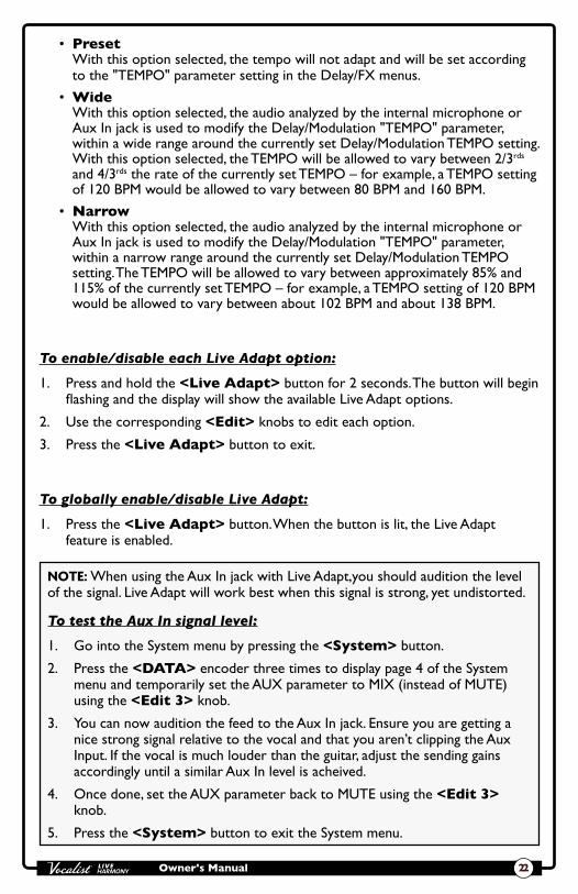
• Preset With this option selected, the tempo will not adapt and will be set according to the "TEMPO" parameter setting in the Delay/FX menus.
• Wide With this option selected, the audio analyzed by the internal microphone or Aux In jack is used to modify the Delay/Modulation "TEMPO" parameter, within a wide range around the currently set Delay/Modulation TEMPO setting. With this option selected, the TEMPO will be allowed to vary between 2/3rds and 4/3rds the rate of the currently set TEMPO – for example, a TEMPO setting of 120 BPM would be allowed to vary between 80 BPM and 160 BPM.
• Narrow With this option selected, the audio analyzed by the internal microphone or Aux In jack is used to modify the Delay/Modulation "TEMPO" parameter, within a narrow range around the currently set Delay/Modulation TEMPO setting. The TEMPO will be allowed to vary between approximately 85% and 115% of the currently set TEMPO – for example, a TEMPO setting of 120 BPM would be allowed to vary between about 102 BPM and about 138 BPM.
To enable/disable each Live Adapt option:
1. Press and hold the <Live Adapt> button for 2 seconds. The button will begin flashing and the display will show the available Live Adapt options.
2. Use the corresponding <Edit> knobs to edit each option.
3. Press the <Live Adapt> button to exit.
To globally enable/disable Live Adapt:
1. Press the <Live Adapt> button. When the button is lit, the Live Adapt feature is enabled.
NOTE: When using the Aux In jack with Live Adapt,you should audition the level of the signal. Live Adapt will work best when this signal is strong, yet undistorted.
To test the Aux In signal level:
1. Go into the System menu by pressing the <System> button.
2. Press the <DATA> encoder three times to display page 4 of the System menu and temporarily set the AUX parameter to MIX (instead of MUTE) using the <Edit 3> knob.
3. You can now audition the feed to the Aux In jack. Ensure you are getting a nice strong signal relative to the vocal and that you aren’t clipping the Aux Input. If the vocal is much louder than the guitar, adjust the sending gains accordingly until a similar Aux In level is acheived.
4. Once done, set the AUX parameter back to MUTE using the <Edit 3> knob.
5. Press the <System> button to exit the System menu.

Owner's Manual23
LooperThe Live Harmony's built-in Phrase Looper allows you to record a vocal loop, record infinite overdubs on the loop, and undo/redo overdubs during live performance. The Looper is placed last in the signal chain. This allows all enabled effects to be recorded with the loop and allows overdubs to be recorded with different effects applied. The maximum allowable loop recording length is dependent upon whether the Loop Undo function is enabled or disabled. See "Loop Undo" on page 38 for further information on the Loop Undo feature.
Looper FunctionsTo enable the Looper, press and hold the <Down> footswitch. Once enabled, the table at the bottom of the display will show which Looper functions can be accessed by pressing the corresponding footswitches, as shown in the image to the right.
Harmony 2
Harmony LevelVoice 1 Voice 2
Key/Scale
LOOPER READY
DOWN UP A/B
PRESET 1
RECORD EXIT
U01
To use the Looper:
1. Press and hold the <Down> footswitch for 2 seconds. “LOOPER READY” will appear in the display and the <Down> footswitch LED will flash red, indicating the Looper is ready to begin recording.
2. Press the <Down> footswitch to start recording. The <Down> footswitch LED will light solid red and recording will begin, indicated by a recording progress bar in the display.
3. When you are finished recording you can perform one of three functions, they are:
A. Stop Recording & Immediately Start Loop Playback Press the <Down> footswitch to set the loop end point and immediately begin loop playback. Playback is indicated by a play progress bar in the display.
B. Stop Recording & Start Playback Manually Press the <Up> footswitch to set the loop end point – playback will not be initiated. When you're ready to play the loop, press the <Down> footswitch.
C. Clear the Loop & Record it Again If you feel the loop needs to be re-recorded, press the <Up> footswitch two times consecutively – holding it down for about 2 seconds on the second press (the first press will stop recording and the second press will clear the loop). Now repeat steps 2 and 3.
Owner's Manual 24
4. You can now record overdubs. To add an overdub, ensure the loop is playing. If it is not, press the <Down> footswitch to initiate loop playback. Now press the <Down> footswitch to start overdub recording. “OVERDUB” will appear in the display.
5. To stop overdub recording, press the <Down> footswitch again. The loop will continue playing, along with the newly recorded overdub. You now have the option to undo the overdub or add another overdub, as described below.
A. Undo/Redo Overdub Press and hold the <Down> footswitch for 2 seconds to undo the overdub. If you perform the Undo function by accident, press and hold the <Down> footswitch again to perform the Redo function and retrieve the overdub.
NOTE: The Undo feature must be enabled in the System menu to perform this action. See "Loop Undo" on page 38 for more information.
B. Add Another Overdub Repeat steps 4 and 5 to add further overdubs.
NOTE: Each time an overdub is added, the last overdub is merged with the original loop and can no longer be undone using the Undo feature.
6. Press the <Up> footswitch to stop loop playback.
7. Press and hold the <Up> footswitch to clear the loop.
8. Press the <A/B> footswitch to exit Loop mode.
HINT: When recording overdubs, it is possible to change presets then record loop overdubs with different effects applied. When in Loop mode, the <Up>/<Down> footswitches are used for Looper control and therefore will not change the preset. You can change the preset while looping by any one of the following methods:
• Turn the <DATA> encoder,
• Exit Loop mode by pressing the <A/B> footswitch – any loop in memory will remain there, and if the loop is currently playing, it will continue to play.
• For even more convenient preset switching while looping, add an optional FS3X Footswitch for dedicated Looper control. For more information see "FS3X Footswitch Control" on page 31.

Owner's Manual25
Guitar TunerUse the Live Harmony's built-in Tuner to quickly and easily tune your guitar.
To tune your guitar with the built-in Tuner:
1. Press and hold the <Up> footswitch for approximately 2 seconds or until the Guitar Tuner appears in the LCD display and the LED above the footswitch begins flashing.
2. Play an open string on your guitar. The detected note will be shown in the middle of the LCD display and indicators will point you in the direction the string needs to be tuned. Adjust the string’s pitch until the proper note is displayed and the upward-facing arrow is pointed as close as possible to the center line. Tune the remaining strings in the same manner.
3. Press any footswitch to exit the Guitar Tuner.
Harmony 2
Harmony LevelVoice 1 Voice 2
Key/Scale
E

Owner's Manual 26
PresetsThe Live Harmony has 99 user presets and 99 factory presets. The type of preset loaded can be identified by the letter preceding the preset number in the LCD display. For example, "U01" would signify "User" preset 1 and "F04" would signify "Factory" preset 4. From the factory, the user and factory presets are identical. The difference is that factory presets cannot be overwritten and user presets are meant to be overwritten. You can load and edit either a user or factory preset as a starting point and then store it to a user preset location.
Any changes made to effect parameters – with the exception of the Gold Channel effects – must be stored to a user preset to be retained. Changing these parameters will cause the Store button to light, indicating that changes have been made to the preset and must be stored. If the preset is changed or the unit is powered down before the changes have been stored, the changes will be lost.
Presets can be selected using either the DATA encoder or the Up/Down footswitches. Using the DATA encoder allows for quick navigation through presets, while using the Up/Down footswitches navigate one preset at a time and provide hands-free control.
Navigating between the user and factory presets is straightforward. When user preset 99 is reached, advancing to the next preset up will select the first preset of the factory preset bank. And when factory preset 99 is reached, advancing up will select the first preset of the user preset bank. The same type of preset bank navigation occurs when navigating downward through presets.
To select a preset with the DATA encoder:
1. From Preset mode (this is the normal operating mode), rotate the <DATA> encoder clockwise to move up through presets.
2. Rotate the <DATA> encoder counter-clockwise to move down through presets.
NOTE: Presets can load automatically or manually using the DATA encoder. See "Preset Load" on page 37 for more information on this feature.
To select a preset with the UP/DOWN footswitches:
1. Press the <Up> footswitch to select the next preset up.
2. Press the <Down> footswitch to select the next preset down.
NOTE: Pressing and holding the <Up> or <Down> footswitches will perform secondary functions assigned to these footswitches, as indicated by the screening on the chassis.

Owner's Manual27
To store a preset:
1. Press the <Store> button. The Store button will begin flashing and the first character of the preset’s name will now have a cursor under it.
2. If you do not wish to rename the preset, go to step 4. If you do wish to rename the preset, turn the <Edit 4> (CHARACTER) knob to change the selected character. Turn the <Edit 3> (CAPS) knob to change between upper and lower case letters. Turn the <Edit 2> (MOVE) knob to insert and remove spaces to the left of the selected character. The preset name can contain up to 16 characters.
3. Turn the <Edit 1> (POSITION) knob to move the cursor and select the next character for editing. Using the four <Edit> knobs, continue making the desired changes until the preset name is complete.
4. Press the <Store> button again. The display will read “STORE TO:”. If you do not want to change the preset location, go to step 5. If you do want to change the preset location, turn the <DATA> encoder to select the desired user preset location. This process will overwrite the preset currently residing in the selected location.
5. Press the <Store> button again to store the preset.
To copy a preset to another preset location:
1. Select the preset you would like to copy using the <DATA> encoder or <Up>/<Down> footswitches.
2. Press the <Store> button. The Store button will begin flashing and the first character of the preset’s name will now have a cursor under it.
3. Press the <Store> button again. The display will read “STORE TO:”. Turn the <DATA> encoder to select the user preset location to copy the preset to. This process will overwrite the preset currently residing in the selected location.
4. Press the <Store> button again to store the preset.
HINT: Press any button or footswitch other than <Store> at any time during the store procedure to cancel the operation.

Owner's Manual 28
Preset A/B PartsEach preset has two parts, referred to as “A” and “B”. Vocal effects can be independently enabled or disabled in each part. This feature can be helpful for applying different effects within a song without having to change presets, such as enabling delays, distortion, or harmony effects on certain words or vocal phrases. These parts are toggled using the A/B footswitch. The A/B footswitch can be configured for Toggle, Momentary, or Auto operation. For information on configuring the A/B footswitch, see "A/B Footswitch Configuration" on page 34.
To store A/B parts:
1. Select the desired preset using the <Up> and <Down> footswitches or the <DATA> encoder.
2. Ensure part A is selected (indicated by the "A" LED above the A/B footswitch). If it is not, press the <A/B> footswitch to select it.
3. Enable the Vocal effects you wish to use for part A by pressing their corresponding buttons (e.g., <FX>, <Reverb>, etc.).
4. Press the <A/B> footswitch to switch to part B (indicated by the "B" LED above the A/B footswitch). Enable the Vocal effects you wish to use for part B by pressing their corresponding buttons (e.g., <Harmony 1>, <Delay>, etc.).
5. Now that both parts have been configured, store the preset by pressing the <Store> button and following the store procedure. See "Presets" on page 26 for further information on storing presets.

Owner's Manual29
Set ListsThe Live Harmony lets you organize presets into groups called “Set Lists". A Set List contains a group of up to twenty presets placed in any order, so you can easily step through the presets you need to during a performance. There are five available Set Lists: Favorites, Set List A, Set List B, Set List C, and Set List D. Pressing the <Set List> button repeatedly will cycle through these Set Lists.
To create or edit a Set List:
1. Press the <Set List> button repeatedly until the desired Set List has been selected.
2. Press and hold the <Set List> button to enter the selected Set List's edit menu. The LCD display will display the Set List, with the first preset in the Set List selected.
3. Turn the <Edit 4> knob to select the preset you would like to reside in slot 1.
4. Turn the <Edit 1> knob or press the <Up>/<Down> footswitches to select the different preset slots in the Set List. Repeat steps 3 and 4 until all desired presets have been assigned in the Set List.
5. To reorder presets in the Set List, turn the <Edit 1> knob to select the preset you wish to move then turn the <Edit 2> knob to move the selected preset up or down the list.
6. When finished editing the Set List, press the flashing <Set List> button to exit. The Set List is now operational and will be identified in the LCD display with a character placed before the preset number. Turn the <DATA> encoder or press the <Up> and <Down> footswitches to navigate the presets in the Set List.
7. To exit the selected Set List and return to Preset mode, press the <Set List> button repeatedly until you just pass "Set List: D", and the leftmost character in the LCD display reads "U" (user preset) or "F" (factory preset).
NOTE: Changes to Set Lists are automatically stored in the Live Harmony. Presets can be edited and stored while using the Set List feature. However, it is important to note that any changes made to a preset that is used in more than one Set List will change the preset in all Set Lists.
To select a configured Set List for use:
1. Press the <Set List> button repeatedly until the desired Set List has been selected. Set Lists can be identified by the character preceding the preset number in the LCD display, these identifiers are: "*" = Favorites, "A" = Set List A, "B" = Set List B, "C" = Set List C, and "D" = Set List D.
2. Once the Set List has been selected, use the <UP>/<Down> footswitches or <DATA> encoder to navigate presets within the Set List.
3. To exit the selected Set List and return to Preset mode, press the <Set List> button repeatedly until you just pass "Set List D", and the character preceding

Owner's Manual 30
the preset number in the LCD display reads "U" (user preset) or "F" (factory preset).
HINT: The Live Harmony provides an alternative way of quickly adding presets to the Favorites Set List.
To quickly add a preset to the Favorites Set List:
1. From Preset mode, select the preset which you want to add to the Favorites Set List.
2. Hold down the <Set List> button until the Favorites Set List is displayed in the LCD display. You will notice that the selected preset was automatically added to the next available empty slot in the list. Turn the <EDIT 2> (MOVE) knob if you wish to change the location of the preset in the list.
3. Press the <Set List> button to exit the Favorites Set List edit menu.
4. The Favorites Set List is now operational and contains the added preset.To exit the Favorites Set List and return to Preset mode, press the <Set List> button repeatedly until you just pass "Set List: D", and the character preceding the preset number in the LCD display reads "U" (user preset) or "F" (factory preset).

Owner's Manual31
FS3X Footswitch ControlThe footswitch functions in the Live Harmony are reassigned when the Looper is enabled. This prevents changing presets and A/B status when controlling the Looper functions. An optional DigiTech FS3X Footswitch can be used for full-time Looper control, freeing up the Live Harmony footswitches to be used for full-time preset navigation. This provides streamlined control and quick access to the Looper functions.
FS3X Footswitch Looper Functions:
Mode SwitchPress this footswitch to enable recording, playblack, or overdub recording functions. Press and hold to perform overdub Undo/Redo functions.
Down SwitchPress this footswitch to stop playback or recording. Press and hold to clear the loop and exit Looper mode.
Up SwitchNot used.
NOTE: When using an FS3X Footswitch with the Live Harmony, the EP (Expression Pedal) TYPE parameter in the System menu must be configured for FS3X control (this is the default setting from the factory). See "EP (Expression Pedal) Type" on page 39 for more information on EP TYPE parameter.

Owner's Manual 32
Volume/Expression Pedal ControlThe Live Harmony can accommodate a variety of expression pedals or a volume pedal plugged into the Footswitch input jack for continuous control of various Vocal effect parameters. The Live Harmony must be configured for volume/expression pedal operation before an external controller can be used. For information on configuring the Live Harmony for volume/expression pedal control and to see a full list of controllable Vocal effect parameters, see "EP (Expression Pedal) Type" on page 39 and "EP Parameter, Min, & Max" on page 41.
Volume Pedal:To use a volume pedal for Live Harmony control, the pedal must meet the following requirements:
• Must be a passive guitar volume pedal.
• Must offer a 1/4” TS cable connection and be connected using a TS cable.
• Must use a 250 kOhms or higher pot.
Expression Pedal:To use an expression pedal for Live Harmony control, the pedal must meet the following requirements:
• Must be a resistance-based expression pedal.
• Must offer a 1/4” TRS cable connection and be connected using a TRS cable.
• Must offer a minimum resistance of 10 kOhms.
NOTE: When powering on the Live Harmony with a volume or expression pedal connected, it is advised to rock the pedal through its full range of motion after power-up to ensure the state of the pedal position corresponds to the actual effect setting in the Live Harmony.

Owner's Manual33
System Setup The System menu is used to configure the Live Harmony for your application and is accessed by pressing the <System> button. Pressing the <DATA> encoder navigates the various pages within the System menu and turning the corresponding <EDIT> knobs will edit the on-screen system parameters. This section of the manual describes the available options in this menu and how to access and edit them. Most of these parameters are global and do not require that you store them to a preset. However, there are a couple of exceptions.
Out PadThis system parameter adjusts the amount of output attenuation. By default, the Out Pad is turned off and this will be the correct setting for most applications. When enabled, the Out Pad can attenuate the output signal by up to 15dB in 1dB increments. Use the Out Pad when connecting headphones to the Live Harmony or whenever the outputs need to be attenuated to prevent input clipping of any device the Live Harmony is connected to. Changing this parameter will affect the 1/4" and XLR outputs.
To edit the OUT PAD setting:
1. Press the <System> button.
2. Turn the <Edit 1> knob to select the desired setting.
3. Press the flashing <System> button to exit the System menu.
Owner's Manual 34
A/B Footswitch ConfigurationEach preset has two parts, referred to as “A” and “B”. Vocal effects can be independently enabled or disabled in each part. This feature can be helpful for applying dynamic effects within a song without having to navigate presets, such as enabling delays, distortion, or harmony effects on certain words or vocal phrases. These parts are toggled using the A/B footswitch. The A/B menu item allows you to configure how the A/B footswitch will operate. The selectable options are:
• Toggle With this option selected, A/B parts will toggle with each press of the A/B footswitch.
• Momentary With this option selected, part B will be selected for as long as the A/B footswitch is held down. As soon as you lift your foot, part A will once again be selected.
• Auto With this option selected, the A/B footswitch can switch between "Toggle" and "Momentary" operation on-the-fly. Quickly pressing the A/B footswitch will toggle between A and B parts. If the A/B footswitch is pressed and held, the switch will act as a momentary switch, switching back to the previous state once released.
To change the A/B footswitch configuration setting:
1. Press the <System> button.
2. Turn the <Edit 2> knob to select the desired setting.
3. Press the flashing <System> button to exit the System menu.
Owner's Manual35
48 V Phantom PowerThis system parameter enables 48 Volt phantom power on the XLR portion of the Live Harmony Mic/Line In jack and should be enabled when connecting a condenser microphone. Phantom power should be off when connecting a dynamic microphone, ribbon microphone, or a condenser microphone which is powered using another power source (such as an internal battery or external power supply). Failing to turn off phantom power for certain microphones (such as ribbon mics or dynamic mics connected using an unbalanced cable) can damage the microphone. If you are unsure whether or not your microphone requires phantom power, consult the microphone’s documentation or manufacturer.
To edit the 48 V setting:
1. Press the <System> button.
2. Turn the <Edit 3> knob to enable or disable phantom power.
3. Press the flashing <System> button to exit the System menu.
StereoWhen the STEREO parameter is turned on, the Live Harmony’s outputs will be configured for stereo operation (this is the default setting). When the Stereo parameter is turned off, the Live Harmony is configured for mono operation. When configured for mono operation, all outputs will carry the same mono-summed signal. The XLR outputs and 1/4” stereo output will be affected when changing this setting.
To edit the STEREO setting:
1. Press the <System> button.
2. Turn the <Edit 4> knob to turn Stereo on or off.
3. Press the flashing <System> button to exit the System menu.

Owner's Manual 36
GTR XLR LVLWhen connecting your guitar to the Guitar In jack, this system parameter adjusts the guitar signal level fed to the Left, Right and Line outputs – the guitar signal fed to the Guitar Thru jack is not affected by this parameter. Turn this parameter up to use the built-in Guitar effects and pass your guitar signal to the Live Harmony's outputs to be played through a PA system or headphones. Turn this parameter all the way down if you plan to use your guitar signal for triggering harmony and pitch generation only and use your own guitar rig for the performance.
NOTE: This parameter should be fully lowered when connecting the Guitar Thru jack to your own guitar rig. This will prevent your guitar signal from being fed to your guitar rig and the PA system simultaneaously, which could cause phase issues.
To edit the GTR XLR LVL setting:
1. Press the <System> button.
2. Press the <DATA> encoder once to navigate to page 2/6 within the System menu.
3. Turn the <Edit 1> knob to adjust the setting.
4. Press the flashing <System> button to exit the System menu.
GTR SensitivityWhen connecting your guitar to the Guitar In jack, this system parameter adjusts the guitar's incoming signal level. The selectable options are Low, Medium, and High.
To edit the GTR SENSITIVITY setting:
1. Press the <System> button.
2. Press the <DATA> encoder once to navigate to page 2/6 within the System menu.
3. Turn the <Edit 3> knob to adjust the setting. Strum your guitar to test the different settings and determine which setting works best with your guitar. Good practice is to set the setting so the Guitar LED lights green regularly, lights orange occasionally, but never lights red.
4. Press the flashing <System> button to exit the System menu.

Owner's Manual37
Preset LoadWhen selecting presets with the DATA encoder, this system parameter determines whether Live Harmony presets are loaded using a one step or two step process. The selectable options are:
• Auto With this option selected, presets will automatically load as they are selected with the <DATA> encoder.
• Manual With this option selected, presets will require you to select the preset using the <DATA> encoder then press the <DATA> encoder to manually load the preset. This option is useful for eliminating accidental preset changes with the DATA encoder. If you stop on a preset when using the Manual option and don’t press the <DATA> encoder, the preset will revert back to the currently active preset after approximately four seconds.
NOTE: The Preset Load parameter does not affect preset changes using the Up and Down footswitches.
To edit the PRESET LOAD setting:
1. Press the <System> button.
2. Press the <DATA> encoder twice to navigate to page 3/6 within the System menu.
3. Turn the <Edit 1> knob to select the desired setting.
4. Press the flashing <System> button to exit the System menu.
Owner's Manual 38
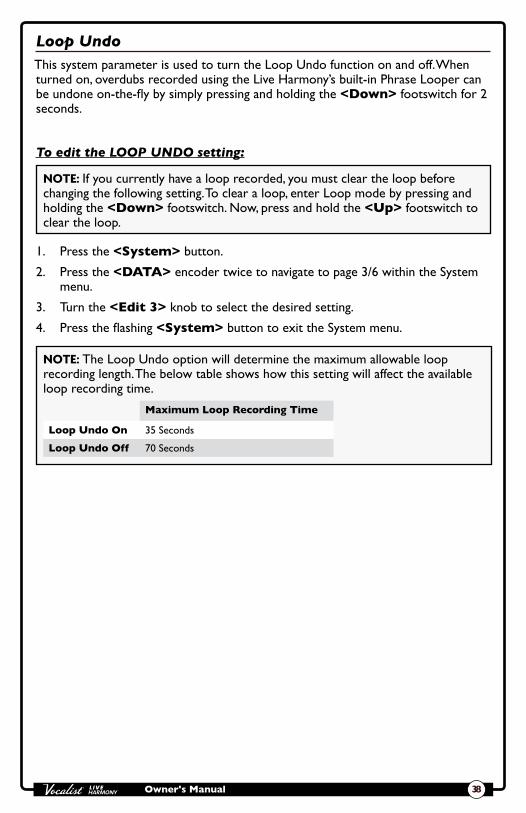
Loop UndoThis system parameter is used to turn the Loop Undo function on and off. When turned on, overdubs recorded using the Live Harmony’s built-in Phrase Looper can be undone on-the-fly by simply pressing and holding the <Down> footswitch for 2 seconds.
To edit the LOOP UNDO setting:
NOTE: If you currently have a loop recorded, you must clear the loop before changing the following setting. To clear a loop, enter Loop mode by pressing and holding the <Down> footswitch. Now, press and hold the <Up> footswitch to clear the loop.
1. Press the <System> button.
2. Press the <DATA> encoder twice to navigate to page 3/6 within the System menu.
3. Turn the <Edit 3> knob to select the desired setting.
4. Press the flashing <System> button to exit the System menu.
NOTE: The Loop Undo option will determine the maximum allowable loop recording length. The below table shows how this setting will affect the available loop recording time.
Maximum Loop Recording Time
Loop Undo On 35 Seconds
Loop Undo Off 70 Seconds
Owner's Manual39
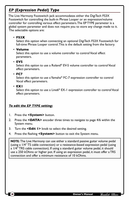
EP (Expression Pedal) TypeThe Live Harmony Footswitch jack accommodates either the DigiTech FS3X Footswitch for controlling the built-in Phrase Looper or an expression/volume controller for controlling various effect parameters. The EP TYPE parameter is a global system parameter and does not require you to store any change made to it. The selectable options are:
• FS3X Select this option when connecting an optional DigiTech FS3X Footswitch for full-time Phrase Looper control. This is the default setting from the factory.
• Volume Select this option to use a volume controller to control Vocal effect parameters.
• EV5 Select this option to use a Roland® EV-5 volume controller to control Vocal effect parameters.
• FC7 Select this option to use a Yamaha® FC-7 expression controller to control Vocal effect parameters.
• EX1 Select this option to use a Line6® EX-1 expression controller to control Vocal effect parameters.
To edit the EP TYPE setting:
1. Press the <System> button.
2. Press the <DATA> encoder three times to navigate to page 4/6 within the System menu.
3. Turn the <Edit 1> knob to select the desired setting.
4. Press the flashing <System> button to exit the System menu.
NOTE: The Live Harmony can use either a standard passive guitar volume pedal (using a 1/4” TS cable connection) or a resistance-based expression pedal (using a 1/4” TRS cable connection). If using a standard guitar volume pedal, it should use a 250 kOhms or higher pot. If using an expression pedal, it must offer a TRS connection and offer a minimum resistance of 10 kOhms.

Owner's Manual 40
Aux In ConfigurationThe AUX system parameter determines whether or not the audio signal from the Aux In jack will be sent to the outputs. The selectable options are:
• Mute Selecting this option will mute the Aux In signal so that you will not hear it in the Live Harmony's outputs. Select this option to use the Aux In jack with Live Adapt.
• Mix Selecting this option will mix the Aux In signal with the processed vocal signal at the Live Harmony’s output stage. Select this option when you wish to monitor the signal plugged into the Aux In jack, such as when connecting a portable music player.
To edit the AUX setting:
1. Press the <System> button.
2. Press the <DATA> encoder three times to navigate to page 4/6 within the System menu.
3. Turn the <Edit 3> knob to select the desired setting.
4. Press the flashing <System> button to exit the System menu.
NOTE: Whenever the Aux In jack is connected to an audio source, it will be used for Live Adapt features instead of the internal microphone.

Owner's Manual41
EP Parameter, Min, & MaxThese system parameters select which vocal effect parameter you would like to control using an optional volume or expression pedal and set the min and max settings for the pedal's toe up and toe down positions. These parameters are not global parameters and do require you to store them to a preset in order to be retained.
• EP Param This option selects which vocal effect parameter will be controlled via a connected volume or expression pedal. A list of available parameters can be found in the table at the end of this section.
• Min This parameter sets the minimum allowable value for the volume or expression pedal’s toe up position.
• Max This parameter sets the maximum allowable value for the volume or expression pedal’s toe down position.
To edit the EP PARAM, MIN, and MAX settings:
1. Press the <System> button.
2. Press the <DATA> encoder four times to navigate to page 5/6 within the System menu.
3. Turn the <Edit 1> knob to select the effect parameter you wish to control.
4. Turn the <Edit 3> knob to select the desired MIN setting and the <Edit 4> knob to select the desired MAX setting
5. Press the flashing <System> button to exit the System menu.
6. To store the changes, press the <Store> button and perform the preset storing procedure. See "Presets" on page 26 for further information on storing user presets.
NOTE: For maximum flexibility when performing, the EP Parameter controls in the System menu are stored as part of the current preset. This allows you to control different effect parameters or change the min/max limits depending on the preset. Remember to store any changes made to the EP parameters to the corresponding preset using the <Store> button.
Vocal Effect Parameters Available for Expression Pedal Control
EP Parameter Minimum Selectable Value Maximum Selectable Value
Harmony Amount 0 99
Harmony Voicing 1 8D 8U
Harmony Voicing 2 8D 8U
Harmony Gain 1 -12 12

Owner's Manual 42
Vocal Effect Parameters Available for Expression Pedal Control
EP Parameter Minimum Selectable Value Maximum Selectable Value
Harmony Gain 2 -12 12
Harmony Gender 1 M50 F50
Harmony Gender 2 M50 F50
Harmony Pan 1 -99 99
Harmony Pan 2 -99 99
Harmony Humanize 1 0 99
Harmony Humanize 2 0 99
Double Amount 0 99
Double Detune -50 50
Double Humanize 0 99
Double Correct 0 99
Pitch FX Level 0 99
Pitch Gender M50 F50
Pitch Shift -12 12
DistFilt Amount 0 99
DistFilt Filter 0 99
DistFilt Distortion 0 99
Mod Amount 0 99
Mod Shape 0 99
Mod Speed Slow 8x
Delay Amount 0 99
Delay Repeats 0 99
Delay Speed 1x Slap 3
Tempo (BPM) 60 300
Reverb Amount 0 99
Reverb Tone -50 50
Reverb PreDelay 0 99
Reverb Tail 0 99
Guitar Mod Amount 0 99
Guitar Mod Shape 0 99
Guitar Mod Speed Slow 8x
Guitar Rvb Amount 0 99

Owner's Manual43
Factory ResetThis system parameter resets all system settings and user presets to their factory default state.
WARNING! Performing the Factory Reset procedure will delete stored presets. It is recommended that you backup presets using the Vocalist Live Librarian preset management software before performing this procedure.
To initiate the Factory Reset procedure:
1. Press the <System> button.
2. Press the <DATA> encoder five times to navigate to page 6/6 within the System menu.
3. Turn the <Edit 1> knob to initiate the Factory Reset procedure.
4. You will receive a confirmation prompt. Turn the corresponding <Edit> knob to make your selection; "Yes" to proceed with Factory Reset, "No" to cancel the procedure. If confirmed, the Factory Reset procedure will be performed then the LCD display will return to displaying the currently loaded preset.
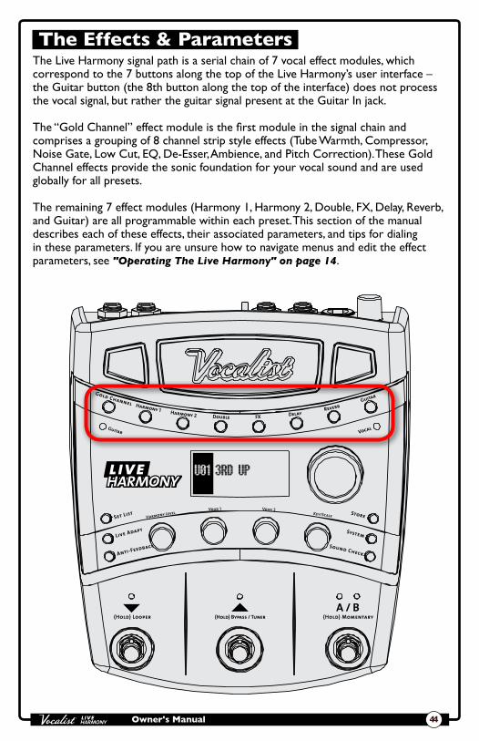
Owner's Manual 44
The Effects & Parameters The Live Harmony signal path is a serial chain of 7 vocal effect modules, which correspond to the 7 buttons along the top of the Live Harmony’s user interface – the Guitar button (the 8th button along the top of the interface) does not process the vocal signal, but rather the guitar signal present at the Guitar In jack.
The “Gold Channel” effect module is the first module in the signal chain and comprises a grouping of 8 channel strip style effects (Tube Warmth, Compressor, Noise Gate, Low Cut, EQ, De-Esser, Ambience, and Pitch Correction). These Gold Channel effects provide the sonic foundation for your vocal sound and are used globally for all presets.
The remaining 7 effect modules (Harmony 1, Harmony 2, Double, FX, Delay, Reverb, and Guitar) are all programmable within each preset. This section of the manual describes each of these effects, their associated parameters, and tips for dialing in these parameters. If you are unsure how to navigate menus and edit the effect parameters, see "Operating The Live Harmony" on page 14.
Harmony 2
Harmony LevelVoice 1 Voice 2
Key/Scale

Owner's Manual45
Gold Channel
Press & Hold To EditHarmony 2
Harmony LevelVoice 1 Voice 2
Key/Scale
To enter the Gold Channel menu, press and hold the <Gold Channel> button for 2 seconds.
Available parameters:
• TYPE This parameter can be seen in the LCD display after entering the Gold Channel menu and is controlled using the <DATA> encoder. These "Types" are preconfigured Gold Channel presets which can initially get you closer to the sound you're after. Once a Type has been selected, you can then edit the Gold Channel parameters to fine-tune the effects to taste. These Types can be reset to the factory default settings after being modified. See "Gold Channel Effects" on page 14 for further information on resetting Types. The following table provides a description of each Type option.
Gold Channel Type Option Description
Bypass All Gold Channel effects are bypassed.
Standard Standard settings that should sound good for most voices.
Std No Gate Standard with no gate.
Std More Comp Standard with more compression.
Std No Corr Standard with no pitch correction.
Less Boom Standard with low band EQ attenuation.
Power Vocal Standard, EQ modified to give a boost around 1.5 kHz.
Clarity Standard with more gain on high band.
Smile Standard with classic smile EQ curve (i.e., low and high frequencies boosted).
Breathy Helps to enhance a breathy singer by enhancing the frequencies near 8 kHz.
Presence Gives a boost near 5 kHz to increase presence of vocal.
Metal Boost at 500 Hz and high band gain.

Owner's Manual 46
Warmth
Press & Hold To EditHarmony 2
Harmony LevelVoice 1 Voice 2
Key/Scale
Warmth adds varying amounts of tube saturation to your vocals. Use Warmth when your vocals require some additional grit, warmth, and character.
Available parameter:
• WARMTH (0-99) This parameter adjusts the amount of tube saturation applied, with 0 being the minimum (no effect) and 99 being the maximum.
To dial in the Warmth effect:
1. Sing into the microphone (or use the Sound Check feature, see "Sound Check" on page 19) and raise the WARMTH parameter until the desired effect level is achieved.
NOTE: The Warmth effect becomes more noticeable as your vocal level increases. To properly set the desired Warmth amount, make sure your microphone gain is set correctly and that your auditioning vocal passage contains sections that are loud enough to enable you to hear the effect at its most prominent.

Owner's Manual47
Compressor
Press & Hold To EditHarmony 2
Harmony LevelVoice 1 Voice 2
Key/Scale
The Compressor helps tame loud vocal passages while raising lower ones, so your vocal’s dynamic range will “sit” better in the mix. Use it to even out your vocals for that up-front, professional vocal sound.
Available parameter:
• COMP (0-99) This parameter adjusts how much compression will be applied, with 0 being the minimum (no effect) and 99 being the maximum.
To dial in the Compressor:
1. Sing into the microphone (or use the Sound Check feature, see "Sound Check" on page 19) and raise the COMP parameter until the desired effect level is achieved. It may help to adjust this parameter while the band is playing to determine how much of the effect is required.
NOTE: The compressor automatically adjusts make-up gain. This eliminates the need for a make-up gain control and makes the compressor easier to set.

Owner's Manual 48
Pitch Correction
Press & Hold To EditHarmony 2
Harmony LevelVoice 1 Voice 2
Key/Scale
Pitch Correction is used to correct notes which are sung slightly out of pitch. For example, if you’re singing a C, and it’s a little flat (but not quite B), pitch correction alters the note so that a more precise C is heard through the sound system.
Pitch Correction can also adapt to changes using the Live Adapt feature. When the PITCH parameter in the Live Adapt menu is set to "Adapt", Pitch Correction will automatically adapt so that it prefers notes that are present in the background music. Otherwise, it will use the chromatic scale for determining which notes to favor when correcting pitch.
Available parameter:
• CORRECT (0-99) This parameter adjusts how much pitch correction will occur, with 0 being the minimum (no effect) and 99 being the maximum.
To dial in Pitch Correction:
1. Sing into the microphone (or use the Sound Check feature, see "Sound Check" on page 19) and raise the CORRECT parameter until the effect becomes just a little too noticeable.
2. Now back it off slightly until a more natural sound is achieved.
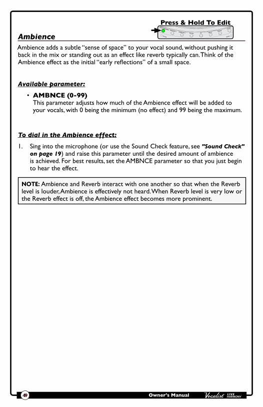
Owner's Manual49
Ambience
Press & Hold To EditHarmony 2
Harmony LevelVoice 1 Voice 2
Key/Scale
Ambience adds a subtle “sense of space” to your vocal sound, without pushing it back in the mix or standing out as an effect like reverb typically can. Think of the Ambience effect as the initial “early reflections” of a small space.
Available parameter:
• AMBNCE (0-99) This parameter adjusts how much of the Ambience effect will be added to your vocals, with 0 being the minimum (no effect) and 99 being the maximum.
To dial in the Ambience effect:
1. Sing into the microphone (or use the Sound Check feature, see "Sound Check" on page 19) and raise this parameter until the desired amount of ambience is achieved. For best results, set the AMBNCE parameter so that you just begin to hear the effect.
NOTE: Ambience and Reverb interact with one another so that when the Reverb level is louder, Ambience is effectively not heard. When Reverb level is very low or the Reverb effect is off, the Ambience effect becomes more prominent.

Owner's Manual 50
EQ
Press & Hold To EditHarmony 2
Harmony LevelVoice 1 Voice 2
Key/Scale
The 3-band EQ shapes the tone of your vocals. It provides low, midrange, and high band filters with sweepable midrange frequency control.
Available parameters:
• LOW (-12 dB-+12 dB) This parameter adjusts the gain of the low frequency shelving filter and can be used to fix a “muddy” vocal sound (using EQ cut) or make thin sounding vocals sound more full (using EQ boost). This is a low shelf filter with a fixed corner frequency at 400Hz.
• MID (-12 dB-+12 dB) This parameter adjusts the gain of the midrange frequency peaking filter and is used for altering the midrange frequencies of your vocal sound. The center frequency of this filter is sweepable using the MIDFREQ parameter.
• MIDFREQ (300 Hz-2 kHz) This parameter works hand-in-hand with the MID parameter. It is used to select the desired center frequency of the mid EQ filter, which determines the range of frequencies altered when adjusting the MID parameter.
• HIGH (-12 dB-+12 dB) This parameter adjusts the gain of the high frequency shelving filter and is used for making your voice sound duller (EQ cut) or brighter (EQ boost). This is a high shelf filter with a fixed corner frequency at 3kHz.
To dial in the EQ:
1. Sing into the microphone (or use the Sound Check feature, see "Sound Check" on page 19) and determine which frequency range needs to be adjusted. Is the vocal dull sounding? Then raise the HIGH parameter. Is it muddy sounding? Then lower the LOW parameter. Does the vocal sound indistinct? Try raising the MID parameter. Does the vocal sound honky or harsh? Try lowering the MID parameter and use the MIDFREQ parameter to zero in on the offending range of frequencies.
2. When adjusting the MID parameter, it helps to first apply an audible amount of boost then sweep the MIDFREQ parameter until you hear the frequency range which requires adjustment. Once the frequency range has been determined, adjust the MID parameter until the desired frequency response is achieved.

Owner's Manual51
De-Esser
Press & Hold To EditHarmony 2
Harmony LevelVoice 1 Voice 2
Key/Scale
The De-Esser tames excessively harsh consonant sounds, referred to as “sibilance”. A de-esser is a frequency selective compressor which is triggered only by the offending sibilant frequencies (between about 5-10 kHz). If you’re experiencing sibilance issues and your vocals sound too dull when lowering the sibilant frequencies with EQ, try using the De-Esser instead.
Available parameter:
• DE-ESS (0-99) This parameter adjusts the amount of de-essing which will occur, with 0 being the minimum (no effect) and 99 being the maximum.
To dial in the De-Esser:
1. Sing into the microphone (or use the Sound Check feature, see "Sound Check" on page 19) and raise the DE-ESS parameter until the sibilant sounds become less prominent (make some “ssssss” sounds in the mic to better hear the affect of the de-esser processing).
2. Fine-tune by ear, ensuring you do not over de-ess, identified by the introduction of a lisp or an overly dull sounding vocal.

Owner's Manual 52
Noise Gate
Press & Hold To EditHarmony 2
Harmony LevelVoice 1 Voice 2
Key/Scale
The Noise Gate removes non-vocal signals from passing through the Live Harmony when you are not singing. This can help clean up the mix and help prevent feedback.
Available parameter:
• GATE (0-99) This parameter allows you to set the Noise Gate’s threshold, with 0 being the highest threshold and 99 being the lowest threshold. In other words, a lower setting will allow the Noise Gate to open for lower level signals and a higher setting will require a louder signal to open the Noise Gate. When the adaptive "GATE" option is enabled in the Live Adapt menu, the Adapt icon A will appear next to this parameter and the parameter will adapt as the surrounding conditions change.
To dial in the Noise Gate:
1. Sing into the microphone (or use the Sound Check feature, see "Sound Check" on page 19) and raise the GATE parameter until the Noise Gate begins cutting off the beginning and/or end of your vocal phrases.
2. Now back it off slightly until the beginning and end of your vocal phrases return and the Noise Gate opens and closes correctly.
3. You can take noise gate control a step further by enabling the adaptive "GATE" feature in the Live Adapt menu. This will allow the gate threshold to adapt to the surrounding conditions and further prevent leakage into the vocal mic. For information on using Live Adapt, see "Live Adapt™" on page 20.

Owner's Manual53
Low Cut Filter
Press & Hold To EditHarmony 2
Harmony LevelVoice 1 Voice 2
Key/Scale
The Low Cut Filter (also known as a high pass filter) prohibits excessively low frequencies (below the usual range of a vocal signal) from passing through the vocal microphone. These excessively low frequencies generally don’t add anything to the vocal’s sound and, when removed, can help with preventing the low end of the mix from becoming "muddy". The cutoff frequency of the Low Cut Filter is fixed at 75Hz.
Available parameter:
• LO CUT (Off, On) This parameter turns the Low Cut Filter on and off.
To dial in the Low Cut Filter:
1. In some applications it may be difficult to hear this filter, but in most cases it will be beneficial to go ahead and enable it. If you do want to audition the effect, sing into the microphone (or use the Sound Check feature, see "Sound Check" on page 19) and turn the Low Cut Filter on.
2. Determine if your voice sounds audibly thinner. You can toggle the Low Cut Filter on and off to further audition the filter. Unless the Low Cut Filter has an adverse effect on your vocal sound, leave it enabled.

Owner's Manual 54
Harmony 1 & 2
Press & Hold To EditHarmony 2
Harmony LevelVoice 1 Voice 2
Key/Scale
Press & Hold To EditHarmony 2
Harmony LevelVoice 1 Voice 2
Key/Scale
Harmony 1 and 2 are used to create the effect of having backup singers singing harmonies. The Live Harmony adds up to two harmony voices to your lead vocal. Each Harmony effect is independently adjustable. Common Harmony parameters can then be edited by turning the knobs from the Preset screen, providing quick access to overall Harmony level, voicings, and key/scale. Changes made to the Harmony effects need to be stored to a preset for later recall.
Available parameters:
• VOICING This parameter allows you to set the desired harmony voice interval. The below table provides a description of each option. Note that the Voicing parameters for both Harmony effects can be accessed from each effect module's edit menu or, for quicker access, they can be adjusted from the Preset screen using the VOICE 1 and VOICE 2 knobs, see the next page for further details.
Harmony Voicing Option Description
8D, 5D, 3D, 3U, 5U, 8U
Each option indicates the voice interval and whether the harmony is above (U) or below (D) the source note. For example, 8D represents a harmony voice an 8th
interval (or one octave) below the source. The 3U option represents a harmony voice a 3rd interval above the source.
• GAIN (-12 dB-+12 dB) This parameter adjusts the Harmony effect mix level, with 0 being the minimum (no effect applied) and 99 being the maximum amount of effect applied.
• GENDER (M50, Off, F50) This parameter is used to amplify the natural gender that is applied to the harmony voices. As GENDER is turned towards F50, voices become more female sounding. As GENDER is turned towards M50, voices become more male sounding. Selecting the "Off" option in the middle bypasses the Gender portion of the effect.
• PAN (-99-+99) This parameter places the harmonies in the stereo field, with -99 representing the full left stereo position, 0 representing center, and 99 being the full right stereo position.
• HUMANIZE (0-99) This parameter adjusts the timing of the harmony voices to make them sound more realistic and more distinct from the source signal, with 0 being the

Owner's Manual55
minimum (harmonies are perfectly timed with the lead voice) and 99 being the maximum (harmonies are very loosely timed with the lead voice).
• AMOUNT (0-99) This parameter adjusts the level of both Harmony effects simultaneously and is accessed by turning the HARMONY LEVEL knob from the Preset screen (see below).
• KEY (A maj-G# min) This parameter sets the harmony key/scale when Live Adapt is not used and is accessed by turning the KEY/SCALE knob from the Preset screen (see below).
The below image shows the four Harmony parameters available by adjusting the knobs from the Preset screen.
Harmony 2
Harmony LevelVoice 1 Voice 2
Key/Scale
AMOUNT VOICING VOICING KEY
79 3D 5D Adapt
Harmony
musIQ Adapt
Edit 1Knob
Edit 2Knob
Edit 3Knob
Edit 4KnobTo dial in the Harmony effect:
1. Sing into the microphone (or use the Sound Check feature, see "Sound Check" on page 19).
2. Press the <HARMONY 1> button to enable the first harmony voice – the button will light when the voice is active.
3. From the Preset screen, turn the <HARMONY LEVEL> knob and ensure the AMOUNT parameter is set high enough to hear the Harmony effect (a setting of between 60-70 should work well).
4. By default, the Harmony Live Adapt feature is enabled. This feature automatically adapts the Harmony key/scale to musical changes in your performance using the internal mic, Aux In jack, or Guitar In jack. If you want to manually set the key/scale, you will need to diable this feature, see "Live Adapt™" on page 20 for further information. From the Preset screen, you can then turn the <KEY/SCALE> knob to select the desired key/scale for the harmony to follow.
NOTE: If Live Adapt Harmony is enabled in the Live Adapt menu you can still set a key/scale but the Live Adapt feature will override this setting as long as it is enabled.

Owner's Manual 56
5. Press and hold the <HARMONY 1> button to edit the parameters for the first harmony voice.
6. Using the <DATA> encoder, select the desired harmony VOICING.
7. Adjust the HUMANIZE parameter until the desired amount of separation and realism is achieved.
8. Adjust the GENDER parameter to determine the amount of gender effect to apply to the harmony voice or set it to "Off" for no gender effect.
9. If listening in stereo, adjust the PAN parameter to place the generated harmony in the stereo field.
10. Fine-tune the GAIN parameter until the harmony effect blends well with the lead vocal. If the desired mix cannot be achieved, try exiting the Harmony menu and adjust the harmony AMOUNT parameter by turning the <HARMONY LEVEL> knob.
11. For two-part harmony, repeat this process for the second harmony voice using the <HARMONY 2> button.
HINT: From the Preset screen, turn the four knobs below the LCD display to quickly adjust the overall harmony level, voice 1 and voice 2 intervals, and the desired key/scale.
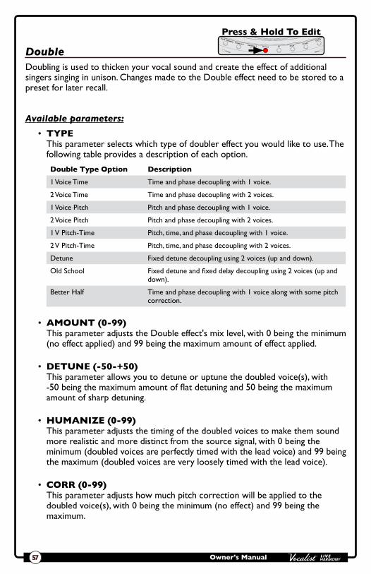
Owner's Manual57
Double
Press & Hold To EditHarmony 2
Harmony LevelVoice 1 Voice 2
Key/Scale
Doubling is used to thicken your vocal sound and create the effect of additional singers singing in unison. Changes made to the Double effect need to be stored to a preset for later recall.
Available parameters:
• TYPE This parameter selects which type of doubler effect you would like to use. The following table provides a description of each option.
Double Type Option Description
1 Voice Time Time and phase decoupling with 1 voice.
2 Voice Time Time and phase decoupling with 2 voices.
1 Voice Pitch Pitch and phase decoupling with 1 voice.
2 Voice Pitch Pitch and phase decoupling with 2 voices.
1 V Pitch-Time Pitch, time, and phase decoupling with 1 voice.
2 V Pitch-Time Pitch, time, and phase decoupling with 2 voices.
Detune Fixed detune decoupling using 2 voices (up and down).
Old School Fixed detune and fixed delay decoupling using 2 voices (up and down).
Better Half Time and phase decoupling with 1 voice along with some pitch correction.
• AMOUNT (0-99) This parameter adjusts the Double effect's mix level, with 0 being the minimum (no effect applied) and 99 being the maximum amount of effect applied.
• DETUNE (-50-+50) This parameter allows you to detune or uptune the doubled voice(s), with -50 being the maximum amount of flat detuning and 50 being the maximum amount of sharp detuning.
• HUMANIZE (0-99) This parameter adjusts the timing of the doubled voices to make them sound more realistic and more distinct from the source signal, with 0 being the minimum (doubled voices are perfectly timed with the lead voice) and 99 being the maximum (doubled voices are very loosely timed with the lead voice).
• CORR (0-99) This parameter adjusts how much pitch correction will be applied to the doubled voice(s), with 0 being the minimum (no effect) and 99 being the maximum.

Owner's Manual 58
To dial in the Double effect:
1. Press and hold the <DOUBLE> button to enter the edit menu.
2. Sing into the microphone (or use the Sound Check feature, see "Sound Check" on page 19) and ensure the AMOUNT parameter is set high enough to hear the effect.
3. Using the <DATA> encoder, select the desired doubling voice TYPE.
4. If you would like to detune or uptune the doubled voice(s), adjust the DETUNE parameter for the desired effect.
5. Adjust the HUMANIZE parameter until the desired amount of distinction and realism is achieved.
6. If you want to apply pitch correction to the doubled voice(s), adjust the CORR parameter until the desired effect is achieved.
7. Fine-tune the AMOUNT parameter until the desired effect balance is achieved.

Owner's Manual59
Pitch FX
Press & Hold To EditHarmony 2
Harmony LevelVoice 1 Voice 2
Key/Scale
The Pitch effects are located in the FX module and provide far-out pitch shifting effects, including Note Hammer, the popular over-the-top synthetic pitch correction effect heard in modern Pop and Hip-Hop recordings. The Pitch effects consist of three different parameter components: TYPE, GENDER, and SHIFT. Each of these components work independently of each other. Changes made to the Pitch effect need to be stored to a preset for later recall.
Available parameters:
• TYPE This parameter allows you to select which type of pitch effect you would like to use. The following table provides a description of each option.
Pitch Type Option Description
Note Hammer Over-the-top synthetic pitch correction effect.
Robo Hammer Note Hammer with a robot effect.
Reso Hammer Note Hammer with a resonator effect.
Resobo Hammer Note Hammer with a resonator and robot effect.
Space Hammer Note Hammer with a resonator effect and pitch sync modulation.
Alien Hammer Note Hammer with some pitch sync modulation and some formant shift.
Pixel Hammer Note Hammer with a pixel effect.
Growl Hammer Note Hammer with growl (i.e., you get some growl when you start to sing louder).
Mod Hammer 20 Note Hammer with pitch sync modulation = 2 pitch periods.
Mod Hammer 25 Note Hammer with pitch sync modulation = 2.5 pitch periods.
Mod Hammer 30 Note Hammer with pitch sync modulation = 3 pitch periods.
Mod Hammer 35 Note Hammer with pitch sync modulation = 3.5 pitch periods.
Mod Hammer 40 Note Hammer with pitch sync modulation = 4 pitch periods.
Mod Hammer 50 Note Hammer with pitch sync modulation = 5 pitch periods.
Mod Hammer 60 Note Hammer with pitch sync modulation = 6 pitch periods.
Mod Hammer 70 Note Hammer with pitch sync modulation = 7 pitch periods.
Mod Hammer 80 Note Hammer with pitch sync modulation = 8 pitch periods.

Owner's Manual 60
Pitch Type Option Description
Robo Robot type effect with no pitch correction.
Reso Resonator effect with no pitch correction.
Resobo Robot and resonator with no pitch correction.
Space Resonator and pitch sync modulation.
Alien Pitch sync modulation and formant shift.
Pixel Pixel effect.
Growl Emulates growl at loud onsets.
Mod 20 Pitch sync modulation = 2 pitch periods.
Mod 25 Pitch sync modulation = 2.5 pitch periods.
Mod 30 Pitch sync modulation = 3 pitch periods.
Mod 35 Pitch sync modulation = 3.5 pitch periods.
Mod 40 Pitch sync modulation = 4 pitch periods.
Mod 50 Pitch sync modulation = 5 pitch periods.
Mod 60 Pitch sync modulation = 6 pitch periods.
Mod 70 Pitch sync modulation = 7 pitch periods.
Mod 80 Pitch sync modulation = 8 pitch periods.
• FX LVL (0-99) This parameter adjusts how much of the selected pitch effect TYPE will be added to your vocals, with 0 being the minimum (no effect) and 99 being the maximum. Note that the SHIFT and GENDER parameters will not be affected by this control.
• KEY (Chromatic, Scalic) Determines whether the selected pitch effect follows chromatic scaling (irrespective of key or scale being sung) or if it uses diatonic shifting and follows the KEY set for the harmonies. You can set this parameter manually or enable the adaptive "PITCH" feature in the Live Adapt menu. When adaptive PITCH is enabled, the Adapt icon A will appear next to this parameter and the parameter will adapt as the detected music key changes. For information on using Live Adapt, see "Live Adapt™" on page 20. The following table provides a description of each available KEY option.
Pitch Key Option Description
Chromatic The algorithm will use the chromatic scale to determine pitch.
Scalic
The algorithm will use the key set for the harmonies to determine pitch. When this option is selected, the set harmony key will be displayed in the LCD display above the KEY parameter). For information on setting the harmony key, see "Harmony 1 & 2" on page 54.

Owner's Manual61
• GENDER (M50, Off, F50) This parameter is used to amplify the natural gender that is applied to the harmony voices. As GENDER is turned towards F50, voices become more female sounding. As GENDER is turned towards M50, voices become more male sounding. Selecting the "Off" option in the middle bypasses the Gender portion of the effect. Note that this parameter is not affected by the FX LVL parameter.
• SHIFT (-12-+12) This parameter determines the amount of transposition applied to the input signal, with negative numbers representing downward pitch transposition and positive numbers representing upward pitch transposition. Note that this parameter is not affected by the FX LVL parameter.
To dial in Pitch FX:
1. Press and hold the <FX> button to enter the edit menu.
2. Sing into the microphone (or use the Sound Check feature, see "Sound Check" on page 19) and raise the FX LVL parameter so you can hear the effect.
3. Select one of the Pitch FX effects using the <DATA> encoder.
4. Select the desired KEY option. If you want the key to follow chromatic scaling, select the "Chromatic" option. If you want the key to be set the same as the Harmony KEY, set the Pitch FX KEY to the "Scalic" setting.
5. If you want the Pitch FX KEY to adapt as the music changes, enable the adaptive "PITCH" feature in the Live Adapt menu. For information on using Live Adapt, see "Live Adapt™" on page 20.
6. Adjust the GENDER parameter to determine the amount of gender effect to apply or set it to "Off" for no gender effect.
7. Adjust the SHIFT parameter to transpose the signal's pitch up or down.
8. Fine-tune the FX LVL parameter until the desired effect level is achieved. Note that the GENDER and SHIFT portions of the effect will not be affected by the FX LVL parameter.

Owner's Manual 62
Distortion/Filter
Press & Hold To EditHarmony 2
Harmony LevelVoice 1 Voice 2
Key/Scale
The Distortion/Filter effects are located in the FX module and can be used to add distortion to your vocals, create lo-fi effects, or create special effects, such as emulating a megaphone. Changes made to the Distortion/Filter effect need to be stored to a preset for later recall.
Available parameters:
• TYPE This parameter allows you to select which type of distortion/filter effect you would like to use. The following table provides a description of each option.
Distortion/Filter Type Option Description
Megaphone 1 Classic megaphone.
Megaphone 2 Small megaphone.
Megaphone 3 Large megaphone.
Radio 1 AM Radio.
Radio 2 Old transistor radio.
Radio 3 Radio in next room.
Phone 1 Cell phone.
Phone 2 8-bit satellite phone.
Ripped Amp 1 Ripped speaker in amp.
Ripped Amp 2 Modified ripped speaker in amp.
Bit Crusher 1 Linear 8-bit quantization.
Bit Crusher 2 Linear 6-bit quantization.
Distortion 1 Feedback resistant distortion.
Half Wave Rect Half wave rectification.
Full Wave Rect Full wave rectification.
• AMOUNT (0-99) This parameter adjusts the Distortion/Filter effect's mix level, with 0 being the minimum (no effect applied) and 99 being the maximum amount of effect applied.
• ROUTING This parameter selects which part of the signal will be affected by the Distortion/Filter effect and provides the following three options:
Lead When this option is selected, the Distortion/Filter effect is applied to the lead voice only. You will hear distortion/filtering on the lead voice and the delay voices which are driven from the lead. The Distortion/Filter effect will not be applied to harmony or doubled voices.

Owner's Manual63
Delay When this option is selected, the Distortion/Filter effect is applied to the delayed vocal only (the Delay effect must be enabled to hear this option).
All When this option is selected, the Distortion/Filter effect will be applied to the lead vocal, delay, harmony, and doubled voices.
• FILTER (0-99) This parameter adjusts the characteristics of the band-pass filter. The change in filter frequencies from 0 to 99 will depend on the currently selected distortion TYPE.
• DISTORT (0-99) This parameter adjusts the amount of distortion introduced into the signal path, with 0 being the minimum (no effect) and 99 being the maximum.
To dial in the Distortion/Filter effect:
1. Press and hold the <FX> button to enter the edit menu.
2. Sing into the microphone (or use the Sound Check feature, see "Sound Check" on page 19).
3. Select one of the Dist/Filter effects using the <DATA> encoder.
4. Ensure the AMOUNT parameter is set high enough to hear the effect.
5. Adjust the ROUTING parameter to select which part of the signal will be processed by the Distortion/Filter effect.
6. Toggle through the Distortion/Filter TYPEs, using the <DATA> encoder, until you find the desired TYPE.
7. Adjust the DISTORT parameter for the desired amount of distortion.
8. If you wish to change the characteristics of the distorted sound, try adjusting the FILTER parameter to emphasize different frequencies.
9. Fine-tune the AMOUNT parameter until the desired effect balance is achieved.

Owner's Manual 64
Modulation
Press & Hold To EditHarmony 2
Harmony LevelVoice 1 Voice 2
Key/Scale
The Modulation effects are located in the FX module and are great for adding motion and depth to your vocal sound and include effects like flanging, chorusing, and vibrato. Changes made to the Modulation effects need to be stored to a preset for later recall.
Available parameters:
• TYPE This parameter selects which type of modulation effect you would like to use. The following table provides a description of each option.
Modulation Type Option Description
Flange Flange with a single tap and moderate feedback.
Feedbck Flange Flange with a single tap and high feedback.
Vibrato Standard vibrato (i.e., pitch modulation).
Chorus Chorus with 1 tap.
Deep Chorus Chorus with 1 tap, medium speed, and a higher SHAPE setting for more depth.
Chorus 4 Wide chorus with 4 taps.
Stereo Chorus Wide chorus with 2 taps panned left and right.
Auto Pan Pans signal between left and right.
Stereo Stutter Hard panning of signal between left and right.
Tremolo Standard tremolo (i.e., volume modulation).
Mono Stutter Modulates the signal on and off.
Rotary Models a Leslie rotary speaker.
Wide Rotary Models a Leslie rotary speaker with more extreme settings.
Warble An extreme variation of vibrato.
• AMOUNT (0-99) This parameter adjusts the Modulation effect's mix level, with 0 being the minimum (no effect applied) and 99 being the maximum amount of effect applied.
• SHAPE (0-99) This parameter controls the depth of the effect, with 0 being the most shallow and 99 being the deepest setting.
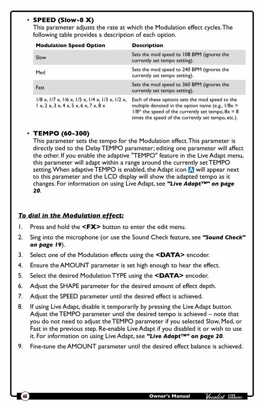
Owner's Manual65
• SPEED (Slow-8 X) This parameter adjusts the rate at which the Modulation effect cycles. The following table provides a description of each option.
Modulation Speed Option Description
Slow Sets the mod speed to 108 BPM (ignores the currently set tempo setting).
Med Sets the mod speed to 240 BPM (ignores the currently set tempo setting).
Fast Sets the mod speed to 360 BPM (ignores the currently set tempo setting).
1/8 x, 1/7 x, 1/6 x, 1/5 x, 1/4 x, 1/3 x, 1/2 x, 1 x, 2 x, 3 x, 4 x, 5 x, 6 x, 7 x, 8 x
Each of these options sets the mod speed to the multiple denoted in the option name (e.g., 1/8x = 1/8th the speed of the currently set tempo, 8x = 8 times the speed of the currently set tempo, etc.).
• TEMPO (60-300) This parameter sets the tempo for the Modulation effect. This parameter is directly tied to the Delay TEMPO parameter; editing one parameter will affect the other. If you enable the adaptive "TEMPO" feature in the Live Adapt menu, this parameter will adapt within a range around the currently set TEMPO setting. When adaptive TEMPO is enabled, the Adapt icon A will appear next to this parameter and the LCD display will show the adapted tempo as it changes. For information on using Live Adapt, see "Live Adapt™" on page 20.
To dial in the Modulation effect:
1. Press and hold the <FX> button to enter the edit menu.
2. Sing into the microphone (or use the Sound Check feature, see "Sound Check" on page 19).
3. Select one of the Modulation effects using the <DATA> encoder.
4. Ensure the AMOUNT parameter is set high enough to hear the effect.
5. Select the desired Modulation TYPE using the <DATA> encoder.
6. Adjust the SHAPE parameter for the desired amount of effect depth.
7. Adjust the SPEED parameter until the desired effect is achieved.
8. If using Live Adapt, disable it temporarily by pressing the Live Adapt button. Adjust the TEMPO parameter until the desired tempo is achieved – note that you do not need to adjust the TEMPO parameter if you selected Slow, Med, or Fast in the previous step. Re-enable Live Adapt if you disabled it or wish to use it. For information on using Live Adapt, see "Live Adapt™" on page 20.
9. Fine-tune the AMOUNT parameter until the desired effect balance is achieved.

Owner's Manual 66
Delay
Press & Hold To EditHarmony 2
Harmony LevelVoice 1 Voice 2
Key/Scale
Delay is an essential effect in vocal processing that creates an echo of your voice. Changes to the Delay module need to be stored to a preset for later recall.
Available parameters:
• TYPE This parameter selects which type of delay effect you would like to use. The following table provides a description of each option.
Delay Type Option Description
Digital Straight up digital delay at currently set tempo.
Dig Ducked 50 Digital delay at currently set tempo with 50% feedback ducking so the louder you sing, the less gets into the delay line.
Dig Ducked 75 Digital delay at currently set tempo with 75% feedback ducking so the louder you sing, the less gets into the delay line.
Dig Ducked 100 Digital delay at currently set tempo with 100% feedback ducking so the louder you sing, the less gets into the delay line.
Digital Pong Digital delays at currently set tempo ponged left to right.
Dig Multitap 1 Digital delays with a multi-tap eighth and quarter pattern.
Dig Multitap 2 Digital delays with a multi-tap triplet pong pattern.
Dig Multitap 3 Digital delays with a multi-tap dotted eighth + quarter note pattern.
Analog Delay at currently set tempo (i.e., an analog-like filtered version of the input is delayed).
Ana Ducked 50 Analog delay at currently set tempo with 50% feedback ducking so the louder you sing, the less gets into the delay line.
Ana Ducked 75 Analog delay at currently set tempo with 75% feedback ducking so the louder you sing, the less gets into the delay line.
Ana Ducked 100 Analog delay at currently set tempo with 100% feedback ducking so the louder you sing, the less gets into the delay line.
Analog Pong Analog delays at currently set tempo ponged left to right.
Ana Multitap 1 Analog delays with a multi-tap eighth and quarter pattern.
Ana Multitap 2 Analog delays with a multi-tap triplet pong pattern.
Ana Multitap 3 Analog delays with a multi-tap dotted eighth + quarter note pattern.
Tape Delay at the tempo, but each time around the delay line is filtered with a peaking filter so the repeats get more and more peaked.
Tape Ducked 50 Tape delay at currently set tempo with 50% feedback ducking so the louder you sing, the less gets into the delay line.
Tape Ducked 75 Tape delay at currently set tempo with 75% feedback ducking so the louder you sing, the less gets into the delay line.
Tape Ducked 100 Tape delay at currently set tempo with 100% feedback ducking so the louder you sing, the less gets into the delay line.
Tape Pong Tape delays at currently set tempo ponged left to right.

Owner's Manual67
Delay Type Option Description
Tape Multitap 1 Tape delays with a multi-tap eighth and quarter pattern.
Tape Multitap 2 Tape delays with a multi-tap triplet pong pattern.
Tape Multitap 3 Tape delays with a multi-tap dotted eighth + quarter note pattern.
Bandpass Delay at the currently set tempo, but each time around the delay line is filtered with a bandpass filter so the repeats get more and more lo-fi.
Band Ducked 50 Bandpassed delay at currently set tempo with 50% feedback ducking so the louder you sing, the less gets into the delay line.
Band Ducked 75 Bandpassed delay at currently set tempo with 75% feedback ducking so the louder you sing, the less gets into the delay line.
Band Ducked 100 Bandpassed delay at currently set tempo with 100% feedback ducking so the louder you sing, the less gets into the delay line.
Band Pong Bandpassed delays at currently set tempo ponged left to right.
Band Multitap 1 Bandpassed delays with a multi-tap eighth and quarter pattern.
Band Multitap 2 Bandpassed delays with a multi-tap triplet pong pattern.
Band Multitap 3 Bandpassed delays with a multi-tap dotted eighth + quarter note pattern.
• AMOUNT (0-99) This parameter adjusts the Delay effect's mix level, with 0 being the minimum (no effect applied) and 99 being the maximum amount of effect applied.
• REPEATS (0-99) This parameter adjusts how much of the delayed signal will be fed back into the delay algorithm and determines how long the delays will continue to repeat, with 0 being the minimum amount of delay repeats and 99 being the maximum amount of delay repeats.
• SPEED (1 X-Slap 3) This parameter adjusts the rate at which the delays repeat. The following table provides a description of each option.
Delay Speed Type Option Description
1 x 1 x the currently set tempo (quarter note).
2 x 2 x the currently set tempo (eighth note).
3 x 3 x the currently set tempo (triplet note).
4/3 x 4/3 x the currently set tempo (dotted eighth note).
1/2 x 1/2 x the currently set tempo (half note).
Slap 1 Slapback delay (80 ms – TEMPO parameter is ignored with this option selected).
Slap 2 Slapback delay (100 ms – TEMPO parameter is ignored with this option selected).
Slap 3 Slapback delay (120 ms – TEMPO parameter is ignored with this option selected).

Owner's Manual 68
• TEMPO (60-300) This parameter allows you to set the tempo for the Delay effect. This parameter is directly tied to the Modulation TEMPO parameter; editing one parameter will affect the other. If you enable the adaptive "TEMPO" feature in the Live Adapt menu, this parameter will adapt within a range around the currently set TEMPO setting. When adaptive TEMPO is enabled, the Adapt icon A will appear next to this parameter and the LCD display will show the adapted tempo as it changes. For information on using Live Adapt, see "Live Adapt™" on page 20.
To dial in the Delay effect:
1. Press and hold the <DELAY> button to enter the edit menu.
2. Sing into the microphone (or use the Sound Check feature, see "Sound Check" on page 19).
3. Ensure the AMOUNT parameter is set high enough to hear the effect.
4. Select the desired Delay TYPE using the <DATA> encoder.
5. Adjust the SPEED parameter until you achieve the "feel" you are after.
6. Adjust the REPEATS parameter until the desired length of delay repeats is achieved.
7. If using Live Adapt, disable it temporarily by pressing the Live Adapt button. Adjust the TEMPO parameter until the desired tempo is achieved – note that you do not need to adjust the TEMPO parameter if you selected Slap 1, Slap 2, or Slap 3 in the previous step. Re-enable Live Adapt if you disabled it or wish to use it. For information on using Live Adapt, see "Live Adapt™" on page 20.
8. Fine-tune the AMOUNT parameter until the desired effect balance is achieved.
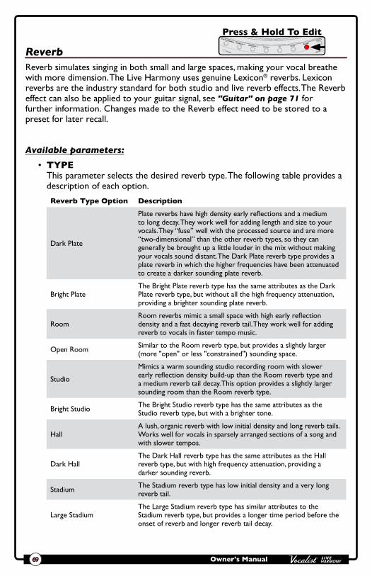
Owner's Manual69
Reverb
Press & Hold To EditHarmony 2
Harmony LevelVoice 1 Voice 2
Key/Scale
Reverb simulates singing in both small and large spaces, making your vocal breathe with more dimension. The Live Harmony uses genuine Lexicon® reverbs. Lexicon reverbs are the industry standard for both studio and live reverb effects. The Reverb effect can also be applied to your guitar signal, see "Guitar" on page 71 for further information. Changes made to the Reverb effect need to be stored to a preset for later recall.
Available parameters:
• TYPE This parameter selects the desired reverb type. The following table provides a description of each option.
Reverb Type Option Description
Dark Plate
Plate reverbs have high density early reflections and a medium to long decay. They work well for adding length and size to your vocals. They “fuse” well with the processed source and are more “two-dimensional” than the other reverb types, so they can generally be brought up a little louder in the mix without making your vocals sound distant. The Dark Plate reverb type provides a plate reverb in which the higher frequencies have been attenuated to create a darker sounding plate reverb.
Bright PlateThe Bright Plate reverb type has the same attributes as the Dark Plate reverb type, but without all the high frequency attenuation, providing a brighter sounding plate reverb.
RoomRoom reverbs mimic a small space with high early reflection density and a fast decaying reverb tail. They work well for adding reverb to vocals in faster tempo music.
Open Room Similar to the Room reverb type, but provides a slightly larger (more "open" or less "constrained") sounding space.
Studio
Mimics a warm sounding studio recording room with slower early reflection density build-up than the Room reverb type and a medium reverb tail decay. This option provides a slightly larger sounding room than the Room reverb type.
Bright Studio The Bright Studio reverb type has the same attributes as the Studio reverb type, but with a brighter tone.
HallA lush, organic reverb with low initial density and long reverb tails. Works well for vocals in sparsely arranged sections of a song and with slower tempos.
Dark HallThe Dark Hall reverb type has the same attributes as the Hall reverb type, but with high frequency attenuation, providing a darker sounding reverb.
Stadium The Stadium reverb type has low initial density and a very long reverb tail.
Large StadiumThe Large Stadium reverb type has similar attributes to the Stadium reverb type, but provides a longer time period before the onset of reverb and longer reverb tail decay.

Owner's Manual 70
• AMOUNT (0-99) This parameter adjusts the Reverb effect's mix level, with 0 being the minimum (no effect applied) and 99 being the maximum amount of effect applied.
• TONE (-50-+50) This parameter adjusts the tone of the Reverb effect, with -50 providing the darkest tone and 50 providing the brightest tone.
• PREDELAY (0-99) This parameter adjusts the predelay of the Reverb effect, with 0 being the minimum (0ms) and 99 being the maximum (50-200ms depending on the selected reverb TYPE). The PREDELAY parameter postpones the onset of reverb, preventing the reverb from "walking on the toes" of the direct vocal sound.
• TAIL (0-99) This parameter adjusts the decay time of the Reverb effect, with 0 being the minimum (shorter decay) and 99 being the maximum (longer decay).
To dial in the Reverb effect:
1. Press and hold the <REVERB> button to enter the edit menu.
2. Sing into the microphone (or use the Sound Check feature, see "Sound Check" on page 19).
3. Ensure the AMOUNT parameter is set high enough to hear the effect.
4. Select the desired Reverb TYPE using the <DATA> encoder.
5. Adjust the TONE parameter until the desired tone is achieved.
6. Adjust the TAIL parameter so that the reverb tail fully decays and "gets out of the way" of the next sung word or phrase.
7. Adjust the PREDELAY parameter until the desired "feel", or amount of distinction between the direct vocal sound and Reverb effect, is achieved (if you're not sure, a setting of 15-20 should provide good results).
8. Fine-tune the AMOUNT parameter until the desired effect balance is achieved.

Owner's Manual71
Guitar
Press & Hold To EditHarmony 2
Harmony LevelVoice 1 Voice 2
Key/Scale
When you connect your guitar to the Guitar In jack on the Live Harmony, you can select to mix your guitar signal to the outputs along with the vocal signal. This lets you hear your guitar signal directly out of the PA system or headphones. When using the Live Harmony in this manner, you have the option to select one of the available modulation effects to apply to your guitar signal. You can also simultaneously apply reverb if desired (the same Reverb effect used for vocals is shared with the guitar). These guitar effects are turned on and off by pressing the <Guitar> button and edited by pressing and holding the <Guitar> button.
The following describes the different effects and parameters available in the Guitar effect module. Note that the Guitar effects are not sent to the Guitar Thru jack, as this connection is meant to be connected to your own personal effects chain and/or amplifier.
Available parameters:
• TYPE This parameter selects the desired guitar effect type. The following table provides a description of each option.
Guitar Type Option Description
Flange Flange with a single tap and moderate feedback.
Feedback Flange Flange with a single tap and high feedback.
Vibrato Standard vibrato (i.e., pitch modulation).
Chorus Chorus with 1 tap.
Deep Chorus Chorus with 1 tap, medium speed, and a higher SHAPE setting for more depth.
Chorus 4 Chorus with 4 taps.
Stereo Chorus Chorus with 2 taps panned left and right.
Auto Pan Pans signal between left and right.
Stereo Stutter Hard panning of signal between left and right.
Tremolo Standard tremolo (i.e., volume modulation).
Mono Stutter Modulates the signal on and off.
Rotary Models a Leslie rotary speaker.
Wide Rotary Models a Leslie rotary speaker with more extreme settings.
Warble An extreme variation of vibrato.
• MOD LVL (0-99) This parameter adjusts the modulation effect's mix level, with 0 being the minimum (no effect applied) and 99 being the maximum amount of effect applied.
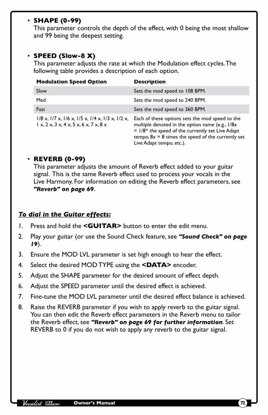
Owner's Manual 72
• SHAPE (0-99) This parameter controls the depth of the effect, with 0 being the most shallow and 99 being the deepest setting.
• SPEED (Slow-8 X) This parameter adjusts the rate at which the Modulation effect cycles. The following table provides a description of each option.
Modulation Speed Option Description
Slow Sets the mod speed to 108 BPM.
Med Sets the mod speed to 240 BPM.
Fast Sets the mod speed to 360 BPM.
1/8 x, 1/7 x, 1/6 x, 1/5 x, 1/4 x, 1/3 x, 1/2 x, 1 x, 2 x, 3 x, 4 x, 5 x, 6 x, 7 x, 8 x
Each of these options sets the mod speed to the multiple denoted in the option name (e.g., 1/8x = 1/8th the speed of the currently set Live Adapt tempo, 8x = 8 times the speed of the currently set Live Adapt tempo, etc.).
• REVERB (0-99) This parameter adjusts the amount of Reverb effect added to your guitar signal. This is the same Reverb effect used to process your vocals in the Live Harmony. For information on editing the Reverb effect parameters, see "Reverb" on page 69.
To dial in the Guitar effects:
1. Press and hold the <GUITAR> button to enter the edit menu.
2. Play your guitar (or use the Sound Check feature, see "Sound Check" on page 19).
3. Ensure the MOD LVL parameter is set high enough to hear the effect.
4. Select the desired MOD TYPE using the <DATA> encoder.
5. Adjust the SHAPE parameter for the desired amount of effect depth.
6. Adjust the SPEED parameter until the desired effect is achieved.
7. Fine-tune the MOD LVL parameter until the desired effect balance is achieved.
8. Raise the REVERB parameter if you wish to apply reverb to the guitar signal. You can then edit the Reverb effect parameters in the Reverb menu to tailor the Reverb effect, see "Reverb" on page 69 for further information. Set REVERB to 0 if you do not wish to apply any reverb to the guitar signal.

Owner's Manual73
Preset Librarian Software You can back up Live Harmony presets and set lists using the free Vocalist Live Librarian preset management software application for PC and Mac. This software will connect to the Live Harmony through the mini USB connector and lets you archive and retrieve presets and set lists to and from your computer.
System Requirements & DownloadTo download the Vocalist Live Librarian preset management software and get the latest information on system requirements, visit the downloads section at http://www.digitech.com/en-US/products/live-harmony.
Firmware UpdatesFirmware updates are performed using the Vocalist Live Librarian software application. Firmware updates can be performed using a Mac or Windows computer with a compatible USB 2.0 or higher connection.

Owner's Manual 74
Preset List
1. B:3RD ABOVE
2. B:3RD BELOW
3. CSN
4. GOLD STNDRD
5. A:DBL B:HARM
6. GUY GAL
7. OTTOTUNE
8. BEATBOX
9. OCTAVES
10. DOUBLE DOWN
11. GOSPEL
12. SOULSISTERS
13. MY TRIO
14. 3u8u UNISON
15. 3RD-5TH DN
16. 3RD-5TH UP
17. DUAL UNISON
18. UNISON
19. 5THS UP/DN
20. OCTAVE DN
21. FEMALE BACK
22. MALE BACK
23. CHOIR
24. BARBER SHOP
25. BASS ALTOS
26. BLIND BOYS
27. WIDE HARM
28. C MAJOR
29. D MAJOR
30. G MINOR
31. A MINOR
32. BAMA HOLDON
33. A MAJ PONG DLY
34. DA BA DEE
35. GTR CHORUS
36. DOUBLE PONG
37. GTR FLG/RVB
38. BRUNO HEAVN
39. DOUBLING
40. LADIES NITE
41. PENTATONIX-2
42. MOTEL CALIF
43. ELVIRA
44. WALKING MOON
45. FUZZY DELAY
46. COME 2 GETHER
47. LUV HAS COME4U
48. ROYALS
49. WITHOUT YOU
50. MERRY GO ROUND
51. HEARTBRK HOTEL
52. SEXY BACK
53. DUET GUY
54. RADIO...
55. ...ACTIVE
56. SOUTHERN +
57. GIRL ON FIRE
58. 3RDS DELAY
59. GTR REVERB
60. WHISKEY LULBY
61. DELAY
62. 1 MORE DAFT
63. WAGONWHEEL
64. MONEY
65. PAPERBACK
66. RING OF FIRE
67. HELLA GOOD
68. PONG CHORUS
69. BUGLE SISTERS
70. FUZZY SHIFT
71. ALL SHE WANTS
72. FREE FALLIN
73. FLANGEVERB
74. DELAY+REVERB
75. GTR CHO/RVB
76. OCEAN VIEW
77. BIG PLATE
78. PARTY ROCK
79. HARMSTORT
80. A MAJ DBL>HARM
81. SOUL OF MAN
82. SUPER BLK HOLE
83. ORINOCO
84. MANHATTAN
85. HRTACHE2NIT
86. HEY HO
87. DUET GAL
88. FIREFLIES
89. BLUESMAN
90. BILLY JEAN
91. WALRUS
92. LARGE HALL
93. MONKS
94. REHAB
95. HONK TONK WOMN
96. BLACK HORSE
97. PAYPHONE
98. BAD ROMANCE
99. DIANE JUNG
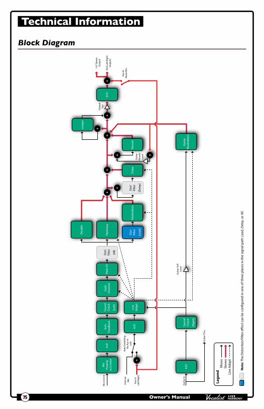
Owner's Manual75
Technical Information
Block Diagram
Lege
nd M
ono
Ster
eoLi
ve A
dapt
Note:
The
Dis
tort
ion/
Filte
r e�e
ct c
an b
e co
n�gu
red
in o
ne o
f thr
ee p
lace
s in
the
sign
al p
ath:
Lead,
Delay
, or A
ll.
XLR
Left
/Rig
htO
utpu
ts
1/4”
Ste
reo
Out
put
Aux
In
Left
/Rig
ht
Inte
rnal
M
icAu
to S
witc
hing
Via
Aux
In
Jack
Aux
In
Mut
e/M
ix
Mic
/Lin
e In
Gui
tar I
n
Gui
tar T
hru
Out
put
Pad
Gui
tar X
LR
Leve
l
Gui
tar
Reve
rbLe
vel
+
++
+
++ +
+
++
Ant
i-Fe
edba
ckSo
und
Chec
kA
/D
A/DM
icPr
eam
pw
/Lim
iter
Pitc
h FX
Dis
t/Fi
lter
(Lea
d)
Gol
dCh
anne
l
A/D
Live
Adap
t
Dis
t/Fi
lter
(All)
Dis
t/Fi
lter
(Del
ay)
Dou
ble
Har
mon
y
Mod
ulat
ion
Del
ayRe
verb
Gui
tar
Mod
ulat
ion
D/A
Loop
er
(Lef
t)
Soun
dCh
eck
(Rig
ht)

Owner's Manual 76
Specifications
Mic InputMicrophone Input: Female XLR, Pin 2 HotImpedance: 3k Ω balancedPhantom Power: +48 VoltsMaximum gain: +60 dBE.I.N. (at max gain): -125 dBu @ 60 dB gain typical (150 Ω source) -128 dBu @ 60 dB gain typical A-weighted (150 Ω source)Maximum Input Level: +18 dBu at minimum gain
Line InputImpedance: 13k Ω balancedMaximum Input Level: +18 dBu at minimum gain
Guitar InputImpedance: 1M Ω
Aux InputAux Input: 1/8” mini stereo jackMaximum Input Level: +20 dBu
Guitar Thru OutputImpedance: 1k Ω
Left/Right OutputsLine Outputs: XLR electronically balancedMaximum Output Level: +5 dBu @ 0 dBFSImpedance: 1k Ω
Headphone/Line OutputHeadphone/Line Output: 1/4” stereo jackImpedance: 50 Ω
PerformanceDynamic Range: 109 dB typical, 22 Hz - 22 kHz, A-weightedFrequency Response: +0/-2.5 dB, 20 Hz - 20 kHzTHD+N: <0.009%, 22 Hz - 22 kHz (mic input to main output) 0 dBu input level <0.006%, 1 kHz, +5 dBu input levelSample Rate: 44.1 kHz

Owner's Manual77
PowerPower Requirements: 9 VDC, 800 mA, 7.2 W, center pin GND, outer sleeve positivePower Adapter: PS0920DC
OtherUSB: USB 2.0 full-speed compliantDimensions: 7.9” (W) x 9.2” (L) x 2.5” (H)Product Weight: 2.7 lbs.
Specifications are subject to change without notice.

78
PHONE: (801) 566-8800
WEB: digitech.com
SUPPORT: digitech.com/en-US/support
Vocalist Live Harmony Owner's Manual 5038827-B
© 2016 Harman. All rights reserved.
DigiTech and Vocalist are registered trademarks of Harman.