OWNER'S MANUAL 1 For All Programmable Digital Thermostat P374-2200.pdf · · 2014-12-19Digital...
21
OWNER'S MANUAL P/N P374-2200 Commercial Systems & Services Carrier Corporation 05/02 7 Day programmable Pre-Programmed Occupied Comfort Unoccupied Energy Savings Auto Changeover Easy To Read Display Thermoglow Backlight Multi-Stage, One for All 3 Security Levels Use with most Air Conditioning & Heating Systems including: 1 or 2 Stage Electric Cooling & Gas Heating, Heat Pump, Electric or Hydronic Heat. * * TOTALINE Programmable Digital Thermostat 1 For All 68 74 HEAT COOL o o Am 6:03 68 Su TOTALINE Meets California Title 24 OCCUPIED1
Transcript of OWNER'S MANUAL 1 For All Programmable Digital Thermostat P374-2200.pdf · · 2014-12-19Digital...
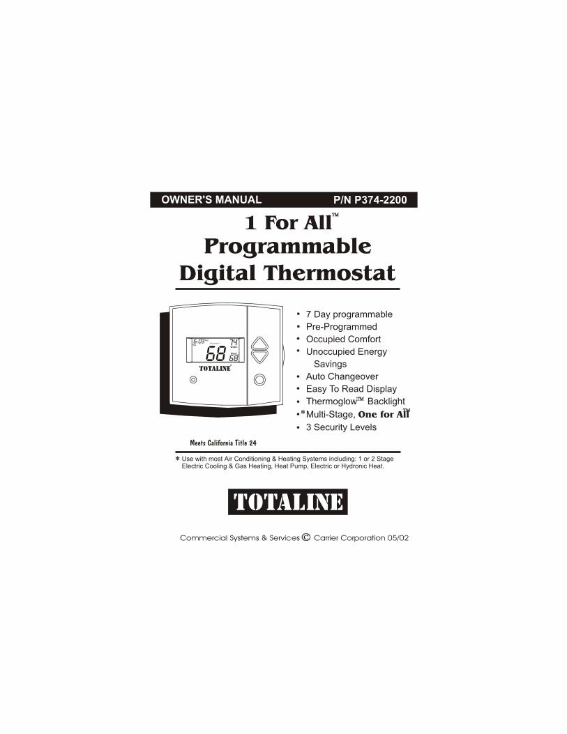
OWNER'S MANUAL P/N P374-2200
Commercial Systems & Services Carrier Corporation 05/02
7 Day programmable
Pre-Programmed
Occupied Comfort
Unoccupied Energy
Savings
Auto Changeover
Easy To Read Display
Thermoglow Backlight
Multi-Stage, One for All
3 Security Levels
Use with most Air Conditioning & Heating Systems including: 1 or 2 StageElectric Cooling & Gas Heating, Heat Pump, Electric or Hydronic Heat.
*
*
TOTALINE
ProgrammableDigital Thermostat
1 For All
68
74HEAT
COOL
o
oAm 6:03
68Su
TOTALINE
Meets California Title 24
OCCUPIED 1
Table Of Contents
FRONT PANEL
DISPLAY
QUICK START Set the clock and go
BASIC OPERATION
PROGRAMMING Occupied / Unoccupied
ADVANCED SETUP
ABOUT ADVANCED OPERATION
WARRANTY
Page 1
CAUTION
Follow Installation Instructions before proceeding.
SET THERMOSTAT TO MODE “OFF” PRIOR TOCHANGING SETTINGS IN SETUP OR RESTORING
FACTORY DEFAULTS.
2
3
5
6
8
12
16
20
Commercial Systems & Services Carrier Corporation 05/02
P/N P374-2200

68
74HEAT
COOL
o
oAm 6:03
68Su
TOTALINE
OCCUPIED 1
Front Panel
Page 2
Backlit LCD Display
Warmer or + Button
Cooler or - Button
Override Button
Heat or Cool Indicator Red = Heat, Green = Cool
67
70HEAT
COOL
AUTOo
oAm 6:03
68S
ProgrammableThermostat
PROGRAM SET CLOCKHOLIDAYFAN
ProgramHolidayFan Set Clock OverrideMode
MODE

1
2
4
3
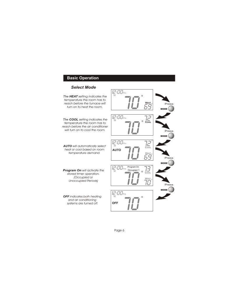
Mode Indicators Selects the operation mode of the equipment. HEAT - indicates the heat mode. COOL - indicates the air conditioning mode. AUTO - indicates the system will automatically changeover between heat and cool modes as the temperature varies. OFF - indicates the entire system is turned off. PROGRAM ON - indicates the stored program is enabled to run. Page 6.
Clock with Day of the Week Indicates the current time and day. This clock is also used to program the timer periods. Page 5.
Room Temperature Display Indicates the current room temperature.
Desired Set Temperature Indicates desired room temperature(s). Page 7.
Display
Page 3
1
1
1
3
4
4
79106
88
88HEAT
COOL
OFFAUTO
ProgramLocked
unoccupied123
SetupOnStartStop
o
oAmPmi2 00
88:
5
SuMTuWThFSa
Fan On
Service Filter
Override
2
8
1
5
6
7
9
10
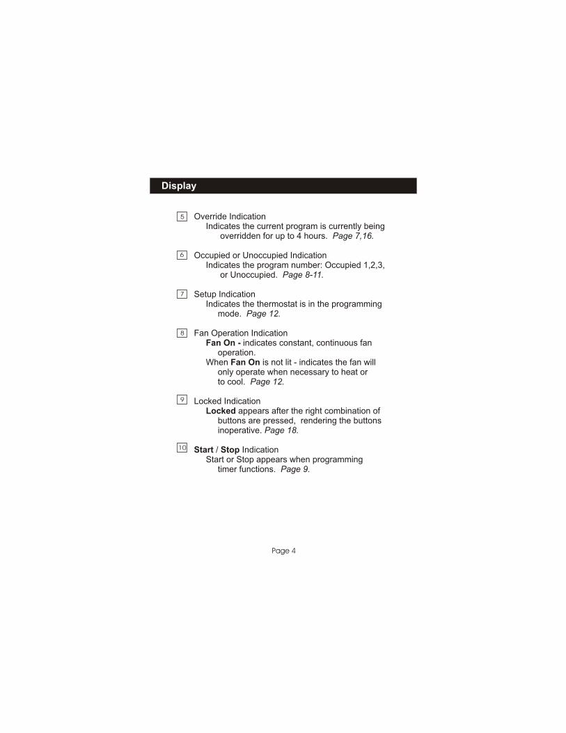
Override Indication Indicates the current program is currently being overridden for up to 4 hours. Page 7,16.
Occupied or Unoccupied Indication Indicates the program number: Occupied 1,2,3, or Unoccupied. Page 8-11.
Setup Indication Indicates the thermostat is in the programming mode. Page 12.
Locked Indication Locked appears after the right combination of buttons are pressed, rendering the buttons inoperative. Page 18.
Start / Stop Indication Start or Stop appears when programming timer functions. Page 9.
Fan Operation Indication Fan On - indicates constant, continuous fan operation. When Fan On is not lit - indicates the fan will only operate when necessary to heat or to cool. Page 12.
Display
Page 4
8
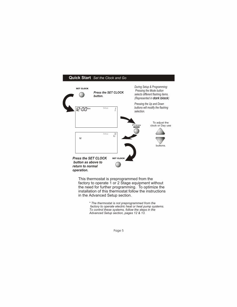
Quick Start Set the Clock and Go
Page 5
Press the SET CLOCKbutton.
Press the SET CLOCK button as above toreturn to normaloperation.
This thermostat is preprogrammed from the factory to operate 1 or 2 Stage equipment without the need for further programming. To optimize the installation of this thermostat follow the instructions in the Advanced Setup section. * The thermostat is not preprogrammed from the factory to operate electric heat or heat pump systems. To control these systems, follow the steps in the Advanced Setup section, pages 12 & 13.
2Setup
M
buttons.
To adjust theclock or Day usePress
SetupAm12:00 i:
SET CLOCK
SET CLOCK
MODE
During Setup & Programming: Pressing the Mode buttonselects different flashing items. (Represented in dark black)
Pressing the Up and Downbuttons will modify the flashingselection.
Basic Operation
Page 6
The HEAT setting indicates thetemperature the room has toreach before the furnace will
turn on to heat the room.
The COOL setting indicates thetemperature the room has to
reach before the air conditionerwill turn on to cool the room.
OFF indicates both heatingand air conditioning
systems are turned off.
AUTO will automatically selectheat or cool based on room
temperature demand.
Program On will activate thestored timer operation.
(Occupied or Unoccupied Periods)
Select Mode
69HEAT o
Pm12:00
70M
:
72COOL
o
Pm12:00
70 M
:
69
72HEAT
COOL
AUTOo
o
Pm12:00
70 M
:
OFF
Pm12:00
70 M
:
70
73HEAT
COOL
Program On
o
o
Pm12:00
70Occupied 1 M
:
Press
MODE
Press
Press
Press
MODE
MODE
MODE
Override
Page 7
Basic Operation
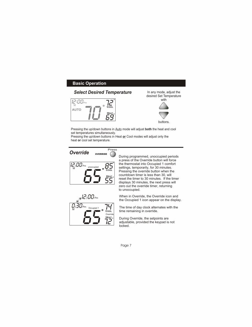
During programmed, unoccupied periodsa press of the Override button will forcethe thermostat into Occupied 1 comfortsettings, temporarily, for 30 minutes.Pressing the override button when the countdown timer is less than 30, willreset the timer to 30 minutes. If the timerdisplays 30 minutes, the next press willzero out the override timer, returning to unoccupied.
When in Override, the Override icon andthe Occupied 1 icon appear on the display.
The time of day clock alternates with thetime remaining in override.
During Override, the setpoints areadjustable, provided the keypad is notlocked.
Press
OVERRIDE
unoccupied
Occupied 1
Override
Pm
Pm
0:30
I2:00
buttons.
In any mode, adjust thedesired Set Temperature
with
Pressing the up/down buttons in Auto mode will adjust both the heat and coolset temperatures simultaneously.Pressing the up/down buttons in Heat or Cool modes will adjust only theheat or cool set temperature.
Select Desired Temperature
69
72HEAT
COOL
AUTOo
o
Pm12:00
70 M
:
55
72
85
74
HEAT
HEAT
COOL
COOL
o
o
o
o
PmI2:00
65
65
M
M

Programming Occupied & Unoccupied Periods
Page 8
Press
Press
Press
Press
Continued
Select the maximum # ofoccupied periods to beused on any one day.Typically 1.
(1,2 or 3)
Adjust the coolingsetpoint for occupied 1.
Adjust the coolingsetpoint for unoccupiedperiods.
Adjust the heatingsetpoint for occupied 1.
(35 - 99 )
(35 - 99 )
(35 - 99 )
MODE
MODE
MODE
MODE
occupied 1
74 occupied COOL1
74
72
occupiedCOOL
HEAT
1
85unoccupiedCOOL
Press the PROGRAM button to enter time period programming.
PressPROGRAM
MODE
Programming Occupied & Unoccupied Periods
Page 9
Press
Press
Press
Press
Press
Continued
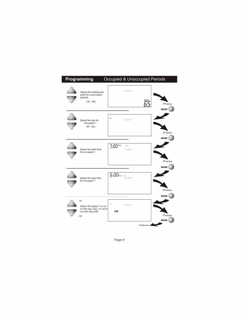
Adjust the heating set-point for unoccupiedperiods.
(35 - 99)
Select the day for Occupied 1.
Adjust the stop timefor occupied 1.
Select Occupied 1 to runon this day (On), or not torun this day (Off).
Adjust the start timefor occupied 1.
(M - Su)
Off
On
MODE
MODE
MODE
MODE
65
unoccupied
HEAT
occupied M
1
occupied
Am Start
M 1
7:00
occupiedPm Stop
M 1 6:00
occupied
ON
M1
Programming Occupied & Unoccupied Periods
Page 10
Press
Press
Press
Press
Press
Continued
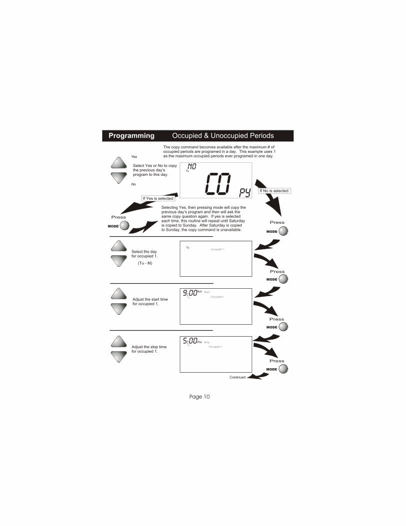
Adjust the start timefor occupied 1.
Adjust the stop timefor occupied 1.
Select the dayfor occupied 1.
Select Yes or No to copythe previous day’sprogram to this day.
Yes
No
If Yes is selected:
If No is selected:
Selecting Yes, then pressing mode will copy theprevious day’s program and then will ask thesame copy question again. If yes is selectedeach time, this routine will repeat until Saturdayis copied to Sunday. After Saturday is copiedto Sunday, the copy command is unavailable.
The copy command becomes available after the maximum # ofoccupied periods are programed in a day. This example uses 1as the maximum occupied periods ever programed in one day.
(Tu - M)
MODE
MODE
MODE
MODE
MODE
Co Py
Tu No
occupied Tu
1
Occupied
Am Start
Tu 1 9:00
Occupied
Pm Stop Tu
1
5:00
Programming Occupied & Unoccupied Periods
Page 11
Press
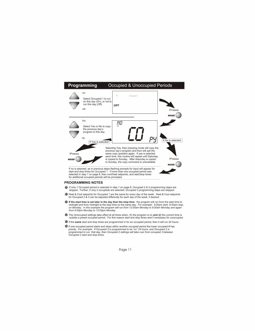
Select Occupied 1 to runon this day (On), or not torun this day (Off).
Off
On
Press
Select Yes or No to copythe previous day’sprogram to this day.
Yes
No
Press
If Yes is selected:If No is selected:
Selecting Yes, then pressing mode will copy theprevious day’s program and then will ask thesame copy question again. If yes is selectedeach time, this routine will repeat until Saturdayis copied to Sunday. After Saturday is copiedto Sunday, the copy command is unavailable.
If no is selected, as in previous steps flashing prompts for input will appear forstart and stop times for Occupied 1. If more than one occupied period wasselected in step 1 on page 8, then cool/heat setpoints, and start/stop timesfor additional occupied periods will be prompted.
PROGRAMMING NOTES
If only 1 Occupied period is selected in step 1 on page 8, Occupied 2 & 3 programming steps areskipped. Further, if only 2 occupieds are selected, Occupied 3 programming steps are skipped.
Heat & Cool setpoints for Occupied 1 are the same for every day of the week. Heat & Cool setpointsfor Occupied 2 & 3 can be adjusted differently for each day of the week, if desired.
If the start time is set later in the day than the stop time, the program will run from the start time tomidnight and from midnight to the stop time on the same day. For example: 9:00pm start, 8:00am stop,on Monday. In this example the program will run from 12:00am Monday to 8:00am Monday and againfrom 9:00pm Monday to 12:00pm Monday.
The Unoccupied settings take effect at all times when: (1) the program is on and (2) the current time is
If the same start and stop times are programmed in for an occupied period, then it will run 24 hours.
If one occupied period starts and stops within another occupied period the lower occupied # haspriority. For example: If Occupied 3 is programmed to be “on” 24 hours, and Occupied 2 isprogrammed to run that day, then Occupied 2 settings will take over from occupied 3 betweenOccupied 2 start and stop times.
outside a preset occupied period. For this reason start and stop times aren’t necessary for unoccupied.
MODE
MODE
MODE
Occupied
OFF
Tu 1
Co Py
W No
Advanced Setup
Page 12
Press
Press
Press
Press
Continued
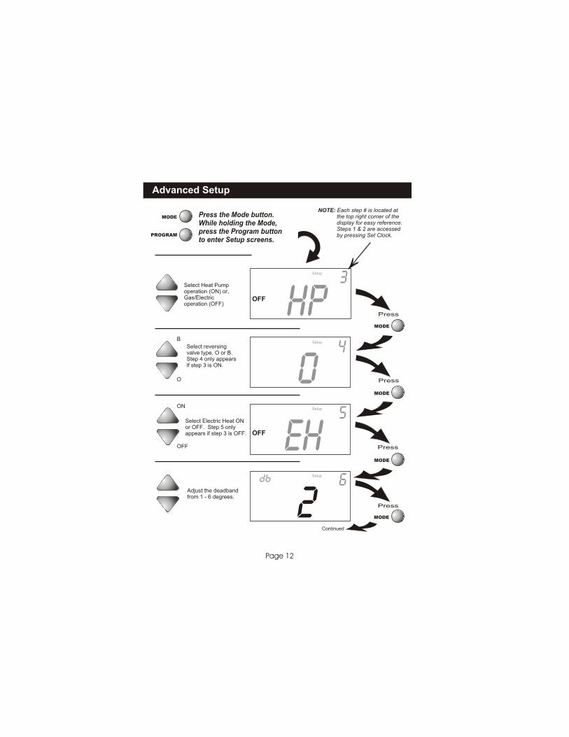
Press the Mode button.While holding the Mode,press the Program buttonto enter Setup screens.
NOTE: Each step # is located at the top right corner of the display for easy reference. Steps 1 & 2 are accessed by pressing Set Clock. PROGRAM
MODE
MODE
MODE
MODE
MODE
Select reversingvalve type, O or B.Step 4 only appears if step 3 is ON.
Select Heat Pumpoperation (ON) or,Gas/Electricoperation (OFF)
3Setup
4Setup
Adjust the deadbandfrom 1 - 6 degrees.
Select Electric Heat ONor OFF. Step 5 onlyappears if step 3 is OFF.
2
eh
o
hp
6
5
Setup
Setup
88
OFF
OFF
ON
O
B
OFF
Advanced Setup
Page 13
Press
Press
Press
Press
Press
Continued
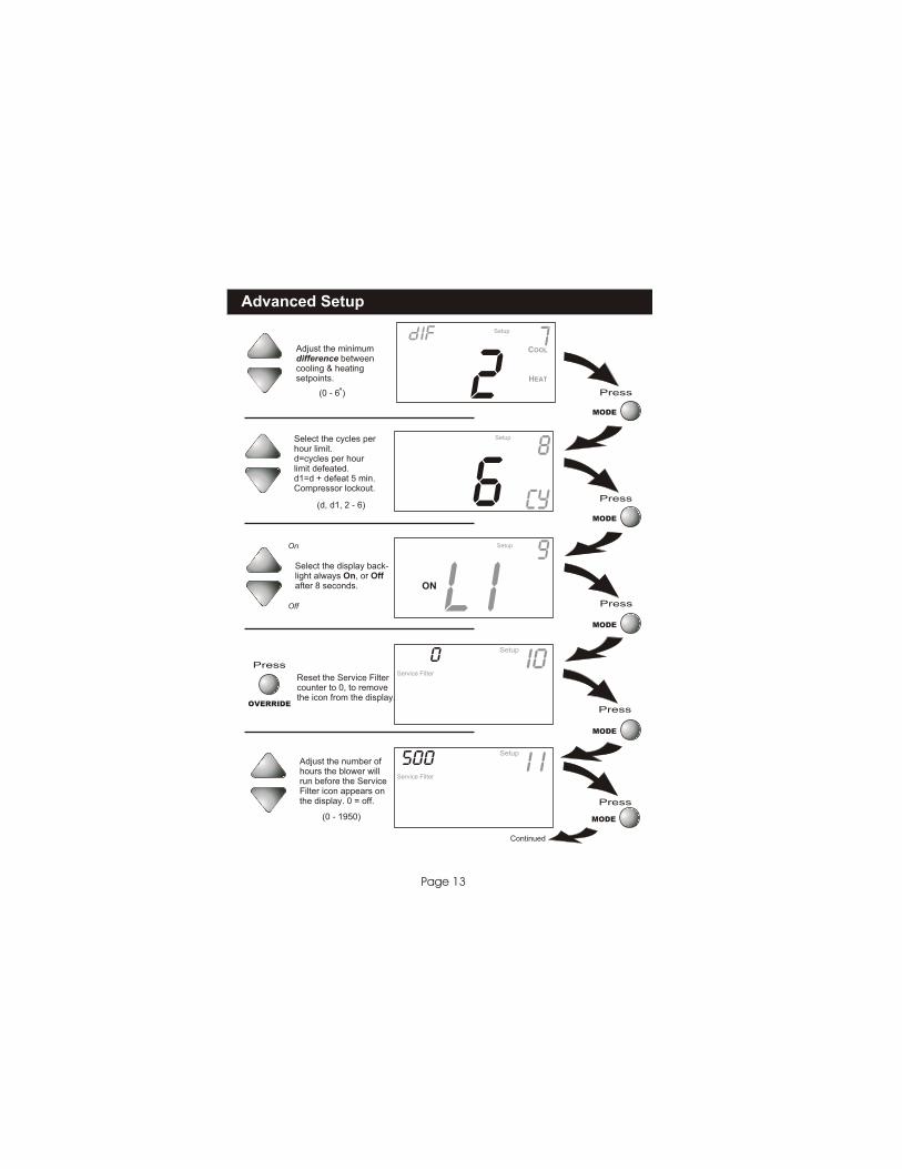
Select the cycles perhour limit.d=cycles per hourlimit defeated.d1=d + defeat 5 min.Compressor lockout.
(d, d1, 2 - 6)
MODE
MODE
MODE
MODE
MODE
6 8
Cy
Setup
Select the display back-light always On, or Offafter 8 seconds.
On
Off L I 9
ON
Setup
Adjust the minimum difference betweencooling & heatingsetpoints.
(0 - 6 )
81f
2 7COOL
HEAT
Setup
i0Setup 0
Service Filter
i iSetup 500
Service Filter
Reset the Service Filtercounter to 0, to removethe icon from the display.
Press
OVERRIDE
Adjust the number ofhours the blower willrun before the ServiceFilter icon appears onthe display. 0 = off.
(0 - 1950)

Advanced Setup
Page 14
Press
MODE
Adjust the minimumallowable cool setpointwhen security is in effect.(Step 15 only appears if step 13 is not 0).
(35 - 99) 65 I5
COOL
LockedSetup lo
MODE
PROGRAM
Press
Press the Mode button. While holding the Mode, press the Program button to enter
Setup screens. If no buttons are press-ed, the display will leave the setup
screens after 60 seconds.
Adjust the maximumallowable heat setpointwhen security is in effect.(Step 14 only appears if step 13 is not 0).
(35 - 99) 80 I4
HEAT
LockedSetup hi
Press
Press
MODE
MODE
Select thermostatoperation in degreesFahrenheit or Centigrade.
C
F F i2Setup
Select the security level:0=no security in effect1=setpoint range limited2=1+ program on all times3=2 + prohibits setpoint changes 0
I3LockedSetup Sec
Advanced Setup
Page 15
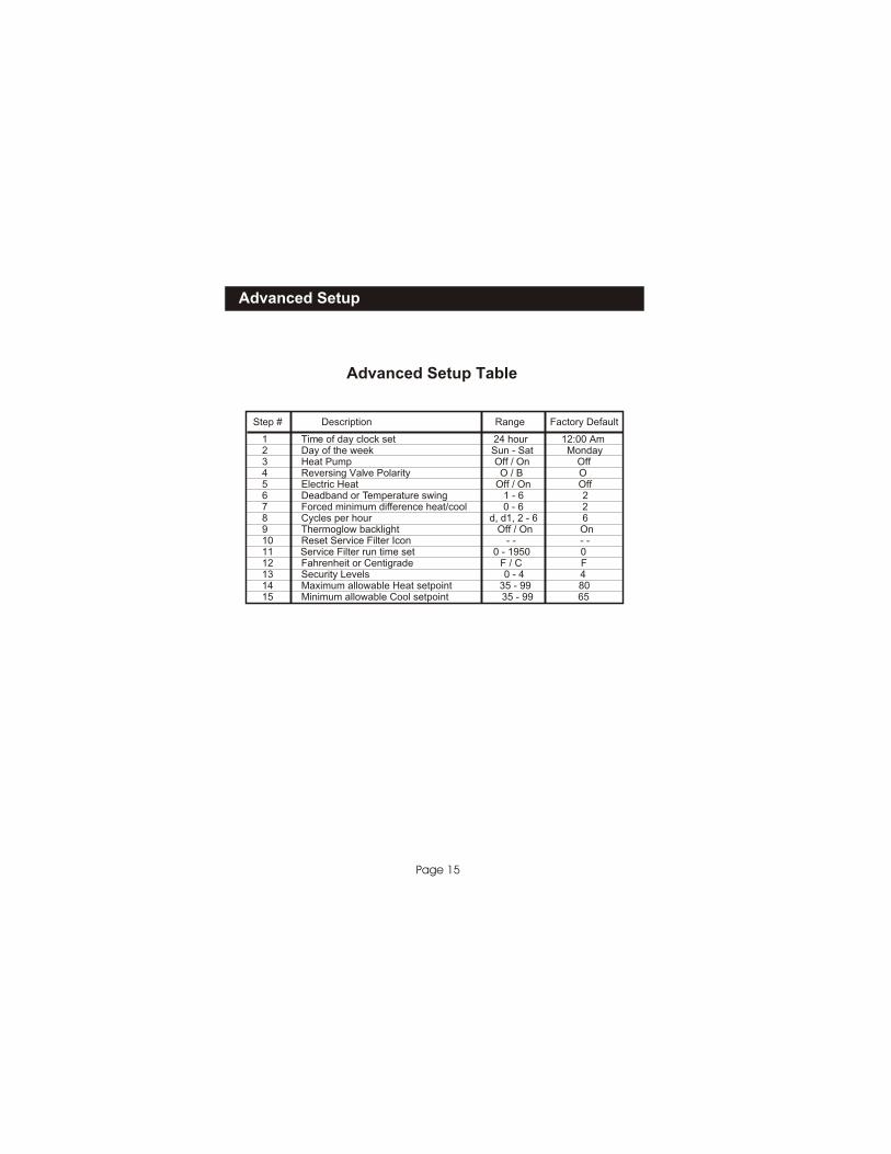
Step # Description Range Factory Default
1 Time of day clock set 24 hour 12:00 Am 2 Day of the week Sun - Sat Monday3 Heat Pump 4 Reversing Valve Polarity
6 7 8 9
11 Service Filter run time set 0 - 1950 012 13
Off / On Off O / B O
5 Electric Heat Off / On OffDeadband or Temperature swing 1 - 6 2Forced minimum difference heat/cool 0 - 6 2Cycles per hour d, d1, 2 - 6 6Thermoglow backlight Off / On On
10 Reset Service Filter Icon - - - -
Fahrenheit or Centigrade F / C FSecurity Levels 0 - 4 4
14 Maximum allowable Heat setpoint 35 - 99 8015 Minimum allowable Cool setpoint 35 - 99 65
Advanced Setup Table
About Advanced Features & Operation
Page 16
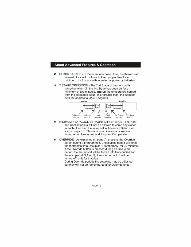
CLOCK BACKUP - In the event of a power loss, the thermostat internal clock will continue to keep proper time for a minimum of 48 hours without external power or batteries. 2 STAGE OPERATION - The 2nd Stage of heat or cool is turned on when (1) the 1st Stage has been on for a minimum of two minutes, and (2) the temperature spread from the setpoint is equal to or greater than: the setpoint plus the deadband, plus 2 degrees.
HeatSetpoint
CoolSetpoint
DeadBand
DeadBand
2 degrees 2 degrees
1st Stageturn on
2nd Stageturn on
1st Stageturn on
2nd Stageturn on
Heating Cooling
MINIMUM HEAT/COOL SETPOINT DIFFERENCE - The Heat and Cool setpoints will not be allowed to come any closer to each other than the value set in Advanced Setup step # 7, on page 13. This minimum difference is enforced during Auto changeover operation.
and Program On
OVERRIDE - As explained on page 7, pressing the Override button during a programmed, Unoccupied period will force the thermostat into Occupied 1, temporarily, for 30 minutes. If the Override button is pressed during an Occupied period, the thermostat will be forced into Unoccupied and occupied # (1,2 or 3), it was forced out of will be off, only for that day. During Override periods the setpoints may be adjusted, but they will not be remembered after Override ends.
the turned

About Advanced Features & Operation
Page 17
EMERGENCY HEAT - To turn on Emergency Heat press in the Fan button. While holding the Fan button press button. The Cool setpoint display
During Emergency Heat the thermostat will turn on the fan and the 2nd stage of heat, when there is a demand for heat, locking out the 1st stage compressor. Exiting Emergency Heat is the same as entering. During Emergency Heat only OFF and HEAT are available. Note: Emergency Heat is only available when the thermostat is controlling a heat pump.
the Up will read ‘EH’.
Press forEmergency Heat
FAN
73eh
74
Am
HEAT
MoI2:00
ENERGY SAVING SMART FAN - If Fan On is selected,the fan will run continuously at all times,except in Off, and will only run if there is a heating or cooling demand in Unoccupied periods.
About Advanced Features & Operation
Page 18
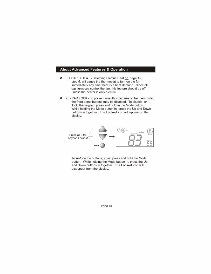
KEYPAD LOCK - To prevent unauthorized use of the thermostat, the front panel buttons may be disabled. To disable, or ‘lock’ the keypad, press and hold in the Mode button. While holding the Mode button in, press the Up and Down buttons in together. The Locked icon will appear on the display.
Press all 3 forKeypad Lockout
To unlock the buttons, again press and hold the Modebutton. While holding the Mode button in, press the Upand Down buttons in together. The Locked icon willdisappear from the display.
MODE
85
55
unoccupied
Pm
COOL
HEAT
Locked WeI2:00
83
ELECTRIC HEAT - Selecting Electric Heat on, page 13, step 6, will cause the thermostat to turn on the fan any time there is a heat demand. Since all control the fan, this feature should be off is only electric.
immediately gas furnaces unless the heater

About Advanced Features & Operation
Page 19
DUAL SETPOINT BEHAVIOR - The adjustable setpoint range is: 35 - 99 degrees in Fahrenheit and 7 - 35 degrees in Centigrade. When in the modes Heat or Cool, this adjustable range is unhampered. When adjusting any Auto mode, including programming Occupied and Unoccupied periods, the thermostat will not allow the Heat setpoint to get closer to the Cool setpoint than the value programmed as the minimum difference in step 7, page 13. When entering the Auto mode from Cool, the Heat and Cool setpoints will remain spread apart by the amount that they were adjusted, prior to entering Auto. For example: If the Cool setpoint was set to 80 while in the Cool mode and the Heat setpoint was adjusted to 70 while in the Heat mode, upon entering the Auto mode the Heat and Cool setpoints would be 80 and 70. Both setpoints would then move up and down together, (in this example spread by 10 degrees), by pressing the up or down buttons. To move the Heat and Cool setpoints closer together, enter the Cool or Heat mode by pressing the Mode button, then adjust the setpoint(s) closer together. Heat is limited to how close it can come to Cool by step 7, page 13. The above applies if the Security level does not equal 4. FACTORY DEFAULTS - If, for any reason it is desirable to return all stored settings back to the factory default settings, press the Mode button. While holding the Mode button in, press the Fan button for 5 sec. All icons will appear. Press and hold in the Fan button until Fd appears. This resets all factory settings. To return to normal operation, press the Mode button twice more.
Warranty
Page 23
One-Year Warranty - This Product is warranted to be free from defects in material and workmanship. If it appears within one year from the date of original installation, whether or notactual use begins on that date, that the product does not meet this warranty, a new orremanufactured part, at the manufacturer’s sole option, to replace any defective part will beprovided without charge for the part itself; PROVIDED the defective part is returned to the distributor through a qualified servicing dealer.
THIS WARRANTY DOES NOT INCLUDE LABOR OR OTHER COSTS incurred for diagnosing,repairing, removing, installing, shipping, servicing or handling of either defective parts orreplacement parts. Such costs may be covered by a separate warranty provided by the installer.
THIS WARRANTY APPLIES ONLY TO PRODUCTS IN THEIR ORIGINAL INSTALLATIONLOCATION AND BECOMES VOID UPON REINSTALLATION.
LIMITATIONS OF WARRANTIES – ALL IMPLIED WARRANTIES (INCLUDING IMPLIEDWARRANTIES OF FITNESS FOR A PARTICULAR PURPOSE AND MERCHANTABILITY) ARE HEREBY LIMITED IN DURATION TOT THE PERIOD FOR WHICH THE LIMITED WARRANTYIS GIVEN. SOME STATES DO NOT ALLOW LIMITATIONS ON HOW LONG AN IMPLIED WARRANTY LASTS, SO THE ABOVE MAY NOT APPLY TO YOU. THE EXPRESSEDWARRANTIES MADE IN THIS WARRANTY ARE EXCLUSIVE AND MANY NOT BE ALTERED,ENLARGED, OR CHANGED BY ANY DISTRIBUTOR, DEALER, OR OTHER PERSONWHATSOEVER.
ALL WORK UNDER THE TERMS OF THIS WARRANTY SHALL BE PERFORMED DURINGNORMAL WORKING HOURS. AL REPLACEMENT PARTS, WHETHER NEW ORREMANUFACTURED, ASSUME AS THEIR WARRANTY PERIOD ONLY THE REMAININGTIME PERIOD OF THIS WARRANTY.
THE MANUFACTURER WILL NOT BE RESPONSIBLE FOR:
1. Normal maintenance as outlined in the installation and servicing instructions or owners manual including filter cleaning and/or replacement and lubrication.2. Damage or repairs required as a consequence of faulty installation, misapplication, abuse, improper servicing, unauthorized alteration or improper operation.3. Failure to start due to voltage conditions, blown fuses, open circuit breakers or other damages due to the inadequacy or interruption of electrical service.4. Damage as a result of floods, winds, fires, lightning, accidents, corrosive environments or other conditions beyond the control of the Manufacturer.5. Parts not supplied or designated by the Manufacturer, or damages resulting from their use. 6. Manufacturer products installed outside the continental U.S.A., Alaska, Hawaii, and Canada.7. Electricity or fuel costs or increases in electricity or fuel costs from any reason whatsoever including additional or unusual use of supplemental electric heat.8. ANY SPECIAL INDIRECT OR CONSEQUENTIAL PROPERTY OR COMMERCIAL DAMAGE OF ANY NATURE WHATSOEVER. Some states do not allow the exclusion of incidental or consequential damages, so the above may not apply to you.
This warranty gives you specific legal rights, and you may also have other rights which may varyform state to state.


![THE YI JING OR “BOOK OF CHANGES”indiana.edu/~p374/Yijing.pdf · Indiana University, Early Chinese Thought [B/E/P374] – Fall 2010 (R. Eno) THE YI JING, OR “BOOK OF CHANGES”](https://static.fdocuments.us/doc/165x107/5a78e3907f8b9ae6228e812d/the-yi-jing-or-book-of-changes-p374yijingpdfindiana-university-early-chinese.jpg)