
Owners & Installation Manual
36
FPI FIREPLACE PRODUCTS INTERNATIONAL LTD. 6988 Venture St., Delta, BC Canada, V4G 1H4 920-082c MODEL: I2450M Classic™ I2450M Wood Fireplace Insert 06.30.21 Owners & Installation Manual Installer: Please complete the details on the back cover and leave this manual with the homeowner. Homeowner: Please keep these instructions for future reference. www.regency-fire.com French Manual: https://bit.ly/3bzeO4T Manuel en Français : https://bit.ly/3bzeO4T 0219WN026S Tested & listed by:
Transcript of Owners & Installation Manual

FPI FIREPLACE PRODUCTS INTERNATIONAL LTD. 6988 Venture St., Delta, BC Canada, V4G 1H4920-082c
MODEL: I2450M
Classic™I2450M Wood
FireplaceInsert
06.30.21
Owners & Installation Manual
Installer: Please complete the details on the back cover and leave this manual with the homeowner.
Homeowner: Please keep these instructions for future reference.
www.regency-fire.comFrench Manual: https://bit.ly/3bzeO4T
Manuel en Français : https://bit.ly/3bzeO4T
0219WN026S
Tested & listed by:

2 | Regency I2450M
| 2Thank you for purchasing a
REGENCY FIREPLACE PRODUCT.
The pride of workmanship that goes into each of our products will give you years of trouble-free enjoyment. Should you have any questions about your product that are not covered in this manual, please contact the REGENCY DEALER in your area.
“This wood heater has a manufacturer set minimum low burn rate that must not be altered. It is against federal regulations to alter this setting or otherwise operate this wood heater in a manner inconsistent with operating instructions in this manual.” Failure to follow the manual details can lead to smoke and CO emissions spilling into the home. It is recommended to have monitors in areas that are expected to generate CO such as heater fueling areas.
“U.S. ENVIRONMENTAL PROTECTION AGENCY Certified to comply with 2020 particulate emission standards using cord wood.” Tested & listed to ASTM E3053. Model Regency I2450M 1.4 g /hr.
“This manual describes the installation and operation of the Regency I2450M wood heater. This heater meets the 2020 U.S. Environmental Pro-tection Agency’s cord wood emission limits for wood heaters. Under specific test conditions this heater has been shown to deliver heat at rates ranging from 14,200 Btu/hr. to 34,660 Btu/hr.” Efficiency is determined using the B415 method resulting in lower and higher heat values. This heater generates the best efficiency when operated using well-seasoned wood and installed in the main living areas where the majority of the chimney is within the building envelope. "
It is against federal regulation to operate this wood heater in a manner inconsistent with operating instructions in this manual, or if elements are deactivated or removed."
CAUTION: BURN UNTREATED WOOD ONLY. OTHER MATERIALS SUCH AS WOOD PRESERVATIVES, METAL FOILS, COAL, PLASTIC,GARBAGE, SULPHUR OR OIL MAY DAMAGE THE HEATER.
"This heater is designed to burn natural wood only. Higher efficiencies and lower emissions generally result when burning air dried seasoned hard-woods, as compared to softwoods or to green or freshly cut hardwoods."
DO NOT BURN:
• Treated wood • Lawn clippings or yard waste • Manure or animal remains
• Coal • Materials containing rubber including tires • Saltwater driftwood or other previously salt water saturated materials
• Garbage • Materials containing plastic • Unseasoned wood
• Cardboard • Waste petroleum products , paints or paint thinners or asphalt products
• Paper products, cardboard, plywood or par-ticle board. The prohibition against burning these materials does not prohibit the use of fire starters made from paper, cardboard, saw dust, wax and similar substances for the purpose of starting a fire in a wood heater.
• Solvents • Materials containing asbestos
• Colored Paper • Construction or demolition debris
• Trash • Railroad ties
Burning these materials may result in release of toxic fumes or render the heater ineffective and cause smoke.
The authority having jurisdiction (such as Municipal Building Department, Fire Department, Fire Prevention Bureau, etc.) should be con-sulted before installation to determine the need to obtain a permit. This unit must be connected to either a listed factory built chimney suitable for use with solid fuels and conforming to, ULC629 in Canada or UL-103HT in the United States of America. or code approved masonry chimney with flue liner.
I2450M is tested and certified to ULC-S628-93 (R1997) and UL1482-2011 (R2015).
SAVE THESE INSTRUCTIONS

Regency I2450M | 3
3| table of contents
ALL PICTURES / DIAGRAMS SHOWN THROUGHOUT THIS MANUAL ARE FOR ILLUSTRATION PURPOSES ONLY.ACTUAL PRODUCT MAY VARY DUE TO PRODUCT ENHANCEMENTS.
CAUTION: To avoid burns or wood splinters, when opening/closing the fuel door or adding wood to the fire, You should always wear appropriate protective gloves to protect your hands from the heat being emitted from this fireplace.
safety label
Safety Label For I2450M ...............................................4
unit dimensions
Unit Dimensions ...........................................................5
installation
Masonry and Factory Built Fireplace Clearances .........6Installation into a Masonry Fireplace .............................7 Before Installing Your Insert ...........................................7Chimney Specifications .................................................7Optional Flue Connector Kit ..........................................7Installation Into a Masonry Fireplace .............................8Altering the Fireplace ....................................................8Draft ...............................................................................8Installing Your Insert ......................................................9Stainless Steel Smoke Deflector Installation ...............10Faceplate and Trim Installation ....................................11Flue Collar Removal and Installation ...........................12Fan Installation ............................................................14Floor Protection ...........................................................15Flue Baffle &Secondary Air Tube Installation ..............15Glass Replacement .....................................................15Wood Door & Handle Assembly ..................................16Brick Installation ..........................................................17Seasoned Wood ..........................................................18
operating instructions
Operating Instructions .................................................19Draft Control ................................................................19First Fire ......................................................................19Fan Operation ..............................................................20Ash Disposal ................................................................20Safety Guidelines and Warnings .................................20
maintenance
Maintenance ................................................................21Creosote .....................................................................21Door Gasket ................................................................21Glass Maintenance ......................................................21Wood Storage ..............................................................21Latch Adjustment .........................................................21Removing Wooden Handle ..........................................21Do Not Burn .................................................................22Vertical Stainless Deflector Replacement....................23Annual Maintenance ....................................................24
parts list
Main Assembly & Options - I2450M ............................25Faceplates - I2450M ....................................................26Brick Panels - I2450M.................................................27
warranty
Warranty .....................................................................28

4 | Regency I2450M
| 4 safety decal
This is a copy of the label that accompanies your Regency Insert. We have printed a copy of the contents here for your review.
NOTE: Regency units are constantly being improved. Check the label on the unit and if there is a difference, the label on the unit is the correct one.
Part
#:
92
0-08
3
Size:
3"Hx20-1/2"W
(fileat100%)
Colou
r:
Blackongrey,exceptforwhatisindicatedasbeing
prin
tedredon
grey.
Mar
11/
19: C
reat
ed d
ecal
April
01/
19: U
pdat
ed d
ecal
April
22/
19: U
pdat
ed d
ecal
Jan
Fe
b M
ar
Apr
M
ay
June
July
Aug
Se
pt
Oct
Nov
D
ec
DATE OF MANUFACTURE
INST
ALLAN
DUS
EON
LYIN
ACC
ORDA
NCEWITHTH
EMA
NUFA
CTUR
ER'SIN
STAL
LATION
AND
OPE
RATING
INST
RUCT
IONS
.INST
ALLAN
DUS
EON
LYIN
MAS
ONRY
FIREP
LACE
ORFA
CTOR
YBU
ILTFIREP
LACE
.CON
TACT
LOC
ALBUILD
INGOR
FIREOF
FICIAL
SAB
OUTRE
STRICT
IONS
AND
INST
ALLA
TION
INSP
ECTION
INYOU
RAR
EA.
INST
ALLE
RET
UTILISE
RSE
LONLE
SINST
RUCT
IONS
DUFA
BRICAN
T.INST
ALLE
RET
UTILISE
RDA
NSUNFO
YERDE
MAÇ
ONNE
RIEOU
PRÉ
FABR
IQUÉ
.AP
PELE
RUN
INSP
ECTE
URENBÂ
TIME
NTOULE
DÉP
ARTE
MENT
INCE
NDIELOC
ALPOU
RCO
NNAÎTR
ELE
SRE
STRICT
IONS
ETLE
SCON
DITION
SD'INSP
ECTION
ÀL'IN
STAL
LATION
DAN
SVO
TRE
SECT
EUR.
LIST
EDFA
CTOR
YBU
ILTFIREP
LACE
INSE
RTCE
RTIFIEDFO
RUS
EINCAN
ADAAN
DU.S.A.
MODE
L/MO
DÈLE
: I24
50M
TEST
ED&LISTE
DBY
/TES
TÉ&APP
ROUV
É:
ULC-S6
28-93(R1
997)/U
L-1482-2011(R
2015)
DONOT
REM
OVETH
ISLAB
EL/NE
PASRE
TIRE
RCE
TTEÉT
IQUE
TTE
522
MINI
MUM
CLEA
RANC
ES T
O
COMB
USTIBL
EMA
TERIAL
S(M
EASU
RED
FROM
INSE
RTBOD
Y)
ADJA
CENT
SIDE
WAL
LA)12in/3
05mm
MANT
ELB)14in/356mm
(3-1/2"
MAN
TEL)
B)17in/4
32mm(12"MAN
TEL)
TOPFA
CING
C)14in/356mm
SIDE
FACING
D)0.5in/13mm
(TOSIDE
SUR
ROUN
D)
OPTION
ALCOM
PONE
NT:FAN
(142-917),EL
ECTR
ICAL
RAT
ING:VOL
TS11
5,60HZ,0.6A
MPS
DANG
ER:R
ISKOF
ELE
CTRICSH
OCK.DISCO
NNEC
TPO
WER
BEF
ORESE
RVICINGUN
IT.DONO
TRO
UTEPO
WER
COR
DUN
DEROR
INFRO
NTOFAP
PLIANC
E.DONO
TCO
NNEC
TTH
ISUNITTO
ACHIMN
EYFLU
ESE
RVICINGAN
OTHE
RAP
PLI-
ANCE
.DONO
TRE
MOVE
BRICK
SOR
MOR
TARINMAS
ONRY
FIREP
LACE
.FOR
USE
WITHSO
LIDWOO
DFU
ELONL
Y.DO
NOTUS
EGR
ATEOR
ELE
VATE
FIRE.B
UILD
WOO
DFIRE
DIREC
TLYON
HEA
RTH.R
ISKOF
SMO
KEAND
FLA
MESPILL
-AG
E,OPE
RATE
ONL
YWITHDO
ORSFU
LLYOP
ENORFU
LLYCL
OSED
.OPE
NFE
EDDOO
RTO
FEE
DFIRE
ONL
Y.R
E-PL
ACEGL
ASSON
LYW
ITHCE
RAMICGL
ASS(5MM
).IN
SPEC
TAN
DCL
EANCH
IMNE
YFR
EQUE
NTLY.UN
DERCE
RTAIN
COND
ITIONS
OFUS
ECR
EOSO
TEBUILD
UPMAY
OCC
URRAP
IDLY.D
ONO
TOV
ERFIRE
,IFIN
SERT
GLO
WSYO
UAR
EOV
ER-FIRING.CAT
ALYT
ICCOM
BUST
ORPAR
T#021-531
PIÈC
EFA
CULTAT
IVE:V
ENTILA
TEUR
(142-917);PU
ISSA
NCEÉL
ECTR
IQUE
:115V
OLTS
,60H
Z,0,6A
DANG
ER:RISQ
UED'ÉLE
CTRO
CUTION
.DÉB
RANC
HERL’A
PPAR
EILA
VANT
TOU
TERÉP
ARAT
ION.NEPA
SFA
IREPA
SSER
LE
FILÉLE
CTRIQU
EDE
VANT
L’AP
PARE
ILNIE
NDE
SSOU
S.NEPA
SRE
LIER
CET
APP
AREILÀUN
ECH
EMINÉE
DES
TINÉ
EÀL’É
VACU
ATIOND’UN
AUT
REAPP
AREIL.NEPA
SEN
LEVE
RDE
BRIQU
ESNID
EMO
RTIERD’UN
ECH
EMINÉE
DEMA
-ÇO
NNER
IE.N
’UTILISE
RQU
EDU
COM
BUST
IBLE
DEBO
ISSOL
IDE.NEPA
SSU
RÉLE
VERLE
SBÛ
CHES
NILES
PLA
CER
SURDE
SGR
ILLE
S,MAISLE
SDÉ
POSE
RDIRE
CTEM
ENTSU
RL’Â
TRE.RISQU
EDE
DÉG
AGEM
ENTDE
FUM
ÉEOUDE
FL
AMME
S:T
OUJO
URSGA
RDER
LES
POR
TESCO
MPLÈ
TEME
NTOUV
ERTE
SOU
FER
MÉES
LOR
SQUE
L’AP
PARE
IL
FONC
TION
NE.D
ANSUN
EMA
ISON
MOB
ILE,TOU
JOUR
SGA
RDER
LES
POR
TESBIEN
FER
MÉES
LOR
SQUE
L’AP
PARE
IL
FONC
TION
NE.O
UVRIRLA
POR
TEUNIQU
EMEN
TPO
URALIME
NTER
LEFE
U.SILES
POR
TESDU
POÊ
LERES
TENT
OU
VERT
ES,TOU
JOUR
SUT
ILISER
LEPA
RE-ÉTINC
ELLE
SFO
URNIPAR
LEFA
BRICAN
T.RE
MPLA
CERLA
VITRE
UNIQU
E-ME
NTPAR
UNE
VITRE
ENVITR
OCÉR
AMIQUE
(5MM).IN
SPEC
TERET
NET
TOYE
RFR
ÉQUE
MMEN
TLA
CHE
MINÉ
E.SEL
ON
LETYP
ED’US
AGE,DELA
CRÉ
OSOT
EPE
UTS’ACC
UMUL
ERRAP
IDEM
ENT.NE
PAS
SUR
CHAU
FFER
;SIL’ENC
ASTR
ABLE
SE
MET
ÀROU
GIR,ILSUR
CHAU
FFE.CAT
ALYS
EURDE
POS
TCOM
BUST
IONPIÈC
ENO 02
1-53
1
CAUT
ION
/ ATT
ENTI
ON
HOTW
HILE
INOPE
RATION
DONO
TTOU
CH.K
EEPC
HILD
REN,
CLOT
HING
AND
FUR
NITU
REAWAY
.CON
TACT
MAY
CAU
SE
SKINBUR
NS.RE
ADABO
VEIN
STRU
CTIONS
.
SURF
ACES
CHA
UDES
LOR
SDE
FON
CTIONN
EMEN
T.NE
PAST
OUCH
ER.ÉLO
IGNE
RLES
ENFA
NTS,LE
SVÊT
EMEN
TSET
LE
SMEU
BLES
.TO
UTC
ONTA
CTA
VEC
LAP
EAU
PEUT
OC
CASION
NERDE
SBR
ÛLUR
ES.L
IRELE
SCO
NSIGNE
SDE
CE
TAPP
AREIL.
FLO
OR
TH
ERM
AL
INSU
LATI
ON
/PR
OTE
CTI
ON
WIT
H A
R V
ALU
E O
F 1.
4 IS
REQ
UIR
ED IF
TH
E U
NIT
IS R
AIS
ED 0
- 2.
5" (6
4MM
) (M
EASU
RED
FR
OM
TH
E B
OTT
OM
OF
THE
APP
LIA
NC
E).
THER
MA
L FL
OO
R P
RO
TEC
TIO
N IS
NO
T R
EQU
IRED
WH
EN U
NIT
IS R
AIS
ER G
REA
TER
TH
AN
2.5
" (6
4MM
) (M
EASU
RED
FR
OM
TH
E B
OTT
OM
OF
THE
APP
LIA
NC
E).
INST
ALL
ER O
BLI
GAT
OIR
EMEN
T U
NE
ISO
LATI
ON
/PR
OTE
CTI
ON
TH
ERM
IQU
E D
'UN
E VA
LEU
R R
DE
1,4
SI L
'APP
AR
EIL
EST
INST
ALL
É À
UN
E D
ISTA
NC
E IN
FÉR
IEU
RE
À 2
.5 P
O (6
4 M
M) D
U S
OC
LE
(MES
UR
E PR
ISE
À P
AR
TIR
DU
BA
S D
E L'
APP
AR
EIL)
.LA
PR
OTE
CTI
ON
TH
ERM
IQU
E N
'EST
PA
S R
EQU
ISE
SI L
'APP
AR
EIL
SE T
RO
UVE
À P
LUS
DE
2.5
PO (6
4MM
) DU
SO
CLE
(MES
UR
E PR
ISE
À P
AR
TIR
DU
BA
S D
E L'
APP
AR
EIL)
.
MADE IN CANADA920-083
(DuplicateSerial#)522
ManufacturedBy: FIREPLACEPRODUCTSINTERNATIONALLTD.6988VENTUREST.,DELTA,BCV4G1H4
2021
2022
2023
2024
2025
Ser
ial N
o./ N
o de
sér
ie
0219
WN
026S
Test
ed a
nd li
sted
to:
U.S
. E
NV
IRO
NM
EN
TAL
PR
OT
EC
TIO
N A
GE
NC
Y C
ER
TIF
IED
TO
CO
MP
LY W
ITH
202
0 PA
RT
ICU
LAT
E E
MIS
SIO
N S
TAN
DA
RD
S U
SIN
G C
OR
D W
OO
D.”
TE
ST
ED
& L
IST
ED
TO
AS
TM
E30
53.
MO
DE
L R
EG
EN
CY
I24
501.
4 G
/H
R. T
HIS
WO
OD
HE
ATE
R N
EE
DS
PE
RIO
DIC
IN
SP
EC
TIO
N A
ND
RE
PAIR
FO
R P
RO
PE
R O
PE
RAT
ION
. CO
NS
ULT
TH
E
OW
NE
R'S
MA
NU
AL
FO
R F
UR
TH
ER
IN
FO
RM
ATIO
N. I
T I
S A
GA
INS
T F
ED
ER
AL
RE
GU
LAT
ION
S T
O O
PE
RAT
E T
HIS
WO
OD
HE
ATE
R I
N A
MA
NN
ER
IN
CO
NS
IST
EN
T W
ITH
T
HE
OP
ER
ATIN
G IN
ST
RU
CT
ION
S IN
TH
E O
WN
ER
'S M
AN
UA
L. COMPO
NEN
TSREQ
UIRED
FORIN
STALL
ATION:5.5"(140m
m)o
r6"(152m
m)S
TAINLE
SSSTE
ELLINER
.C
ER
TIF
IÉ C
ON
FO
RM
E A
UX
NO
RM
ES
202
0 D
U U
.S. E
NV
IRO
NM
EN
TAL
PR
OT
EC
TIO
N A
GE
NC
Y E
N M
ATIÈ
RE
D'É
MIS
SIO
N D
E P
AR
TIC
ULE
S D
E B
OIS
EN
UT
ILIS
AN
T L
E
BO
IS D
E C
OR
DE
. TE
ST
É &
AP
PR
OU
VÉ
AS
TM
E30
53. M
OD
ÈLE
RE
GE
NC
Y I2
450
1.4
G /H
. CE
T A
PPA
RE
IL D
E C
HA
UF
FAG
E A
U B
OIS
DO
IT Ê
TR
E IN
SP
EC
TÉ
PÉ
RI-
OD
IQU
EM
EN
T E
T R
ÉPA
RÉ
PO
UR
FO
NC
TIO
NN
ER
CO
RR
EC
TE
ME
NT.
CO
NS
ULT
ER
LE
MA
NU
EL
D’IN
STA
LLAT
ION
PO
UR
PLU
S D
’INF
OR
MAT
ION
. LA
RÉ
GLE
ME
NTA
TIO
N
FÉ
DÉ
RA
LE IN
TE
RD
IT D
E F
AIR
E F
ON
CT
ION
NE
R U
N T
EL
AP
PAR
EIL
SI L
ES
CO
NS
IGN
ES
D'U
TIL
ISAT
ION
CO
NT
EN
UE
S D
AN
S L
E P
RÉ
SE
NT
MA
NU
EL
NE
SO
NT
PA
S
RE
SP
EC
TÉ
ES
.P
IÈC
ES
RE
QU
ISE
S P
OU
R L
'INS
TALL
ATIO
N :
DO
UB
LUR
E E
N A
CIE
R IN
OX
YD
AB
LE D
E 5
,5 P
O (
140
mm
) O
U 6
PO
(15
2 m
m)
920-
083
Safety Label for I2450M

Regency I2450M | 5
5| dimensions
* *From back of faceplate (not shown) to fuel door opening 7" (178mm)
20"
[508
mm
]

6 | Regency I2450M
| 6 installation
Clearance diagram for installations
Side and Top facing is a maximum of 1-1/2" (38mm) thick. Note: If there is only a top facing and no side facing, refer to (B) mantle (to top of unit) clearance requirements.
Masonry And Factory Built Fireplace Clearances
The minimum required clearances to combustible materials when installed into a masonry or factory built fireplace are listed below.
*Floor Protection
Floor thermal insulation/protection with a R value of 1.4 is required if the unit is raised 0 - 2.5" (0-64mm) (measured from the bottom of the appliance).
Thermal floor protection is not required when unit is raiser greater than 2.5" (64mm) (measured from the bottom of the appliance).
Please check to ensure that your floor protection and hearth will meet the standards for clear-ance to combustibles. Your hearth extension must be made from a non-combustible material. Extending 16" for US and 18" for Canada—measured from the fuel loading door.
CLEARANCES ARE CRITICAL
**Mantel can be installed anywhere in shaded area or higher using the above scale.
Note: Ensure the paint that is used on the mantel and the facing is "heat resistant" or the paint may discolour.
Unit
I2450M
Adjacent Side Wall(to Side)
A
Mantle **(to Top of
Unit)
B
TopFacing
(to Top of Unit)
C
Side Facing
D
MinimumHearth
Extension*
E
MinimumHearth SideExtension*
F
To Top of Unit
G
12" (305mm) 14"(356mm)for 3-1/2" (89mm) mantel
14" (356mm) 1/2"(13mm) to side surround
16" (406mm) USA 8" (203mm) 20" (508mm)
18"(457mm) Canada
17"(432mm)for 12" (305mm) mantel
WOOD INSERT SPECIFICATIONS
Your fireplace opening requires the following minimum sizes:Height: 21.5" (546 mm)Width: 25" (635 mm)Depth: 17" (432 mm)
Two faceplates are available to seal the fireplace opening:StandardW 40" (1 016 mm) x H 30" (762 mm)OversizeW 48" (1 219 mm) x H 33" (838 mm)

Regency I2450M | 7
7| installation
Chimney Specifications
Before installing, check and clean your chimney system thoroughly. If in doubt about its condition, seek professional advice. Your Regency Insert is designed for installation into a masonry fireplace that is constructed in accordance with the require-ments of "The Standard for Chimneys, Fireplaces, Vents, and Solid Fuel Burning Appliance", N.F.P.A. 211, the National Building Code of Canada, or the applicable local code requirements.
The appliance, when installed, must be electri-cally grounded in accordance with local codes or, in the absence of local codes, with the National Electrical Code, ANSI/NFPA 70, or the Canadian Electrical code, CSA C22.1.
Regency Inserts are designed to use either a 5.5" (140mm) or 6" (152mm) flue.
Installation into a Masonry Fireplace
Regency Inserts are constructed with the high-est quality materials and assembled under strict quality control procedures that insure years of trouble free and reliable performance.
It is important that you read this manual thor-oughly and fully understand the safe instal-lation and operating procedures. The more you understand the way your Regency Insert operates, the more enjoyment you will experi-ence from knowing that your unit is operating at peak performance.
Before Installing Your Insert
1. Please read this entire manual before you install and use your new wood insert. Failure to follow instructions may result in property damage, bodily injury or even death. Install and use only in accordance with manufac-turer’s installation and operating instructions.
2. Check your local building codes - Building Inspection Department. You may require a permit before installing your insert. Be aware that local codes and regulations may override some items in the manual.
WARNING: Careless installation is the major cause of safety hazard. Check all local building and safety codes before installation of unit.
3. Notify your home insurance company that you plan to install a fireplace insert or hearth heater.
4. Your fireplace insert is heavy and requires two or more people to move it safely. The insert can be badly damaged by mishandling.
5. If your existing fireplace damper control will become inaccessible once you have installed your Regency Insert, you should either remove or secure it in the open position.
6. Inspect your fireplace and chimney prior to installing your insert to determine that it is free from cracks, loose mortar or other signs of damage. If repairs are required, they should be completed before installing your insert. Do not remove bricks or mortar from your masonry fireplace.
7. Do not connect the insert to a chimney system servicing another appliance or an air distribution duct.
When referencing installation or connec-tion to masonry fireplaces or chimneys, the masonry construction must or shall be code complying.
In Canada this fireplace insert must be installed with a continuous chimney liner of 5.5" (140 mm) or 6" (152 mm) diameter extending from the fireplace insert to the top of the chimney. The chimney liner must conform to the Class 3 requirements of CAN/ULC-S635 or CAN/ULC-S640, Standard for Lining Systems for New Masonry Chimneys.
Draft is the force which moves air from the appliance up through the chimney. The amount of draft in your chimney depends on the length of the chimney, local geography, nearby obstructions and other factors. Too much draft may cause excessive temperatures in the appliance and may cause damage. An uncon-trollable burn or excessive temperature indicates excessive draft. Inadequate draft may cause back puffing into the room and plugging of the chimney. Inadequate draft will cause the appliance to leak smoke into the room through appliance and chim-ney connector joints. Ensure the heater is installed in areas that are not too close to neighbors or in valleys that would cause unhealthy air quality or nuisance conditions.
Optional Flue Connector Kit
The Straight Flue Adaptor (Part #846-504) shown here, may be used to produce a secure connection between your flue connector and the insert collar. Detailed installation instructions are included with the kit.
The following may also be purchased separately if required to complete the install:846-506 6" Flue Adapter 30 degree846-508 6" Flue Adapter 45 degree948-412/P 6" Flue Offset Adapter (offsets back 4")846-527 Flue Connector Kit
Straight adaptor shown with flue connector kit
In the U.S.A., a 5.5 inch (140 mm) or 6 inch (152 mm) diameter, stainless steel, full height chimney liner that meets type HT (21000 F) requirements per UL 1777 must be installed. The full liner must be attached to the insert flue collar and to the top of the existing ma-sonry chimney.
8 | Regency I2450M
| 8 installation
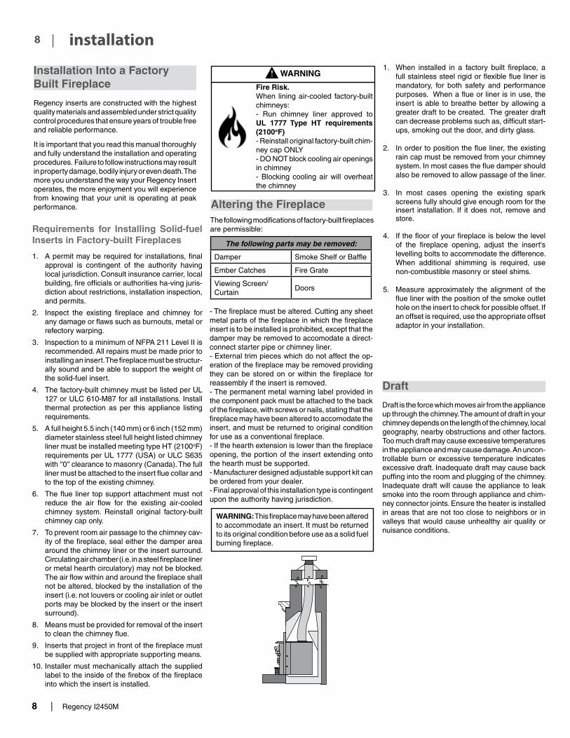
WARNING: This fireplace may have been altered to accommodate an insert. It must be returned to its original condition before use as a solid fuel burning fireplace.
1. When installed in a factory built fireplace, a full stainless steel rigid or flexible flue liner is mandatory, for both safety and performance purposes. When a flue or liner is in use, the insert is able to breathe better by allowing a greater draft to be created. The greater draft can decrease problems such as, difficult start-ups, smoking out the door, and dirty glass.
2. In order to position the flue liner, the existing rain cap must be removed from your chimney system. In most cases the flue damper should also be removed to allow passage of the liner.
3. In most cases opening the existing spark screens fully should give enough room for the insert installation. If it does not, remove and store.
4. If the floor of your fireplace is below the level of the fireplace opening, adjust the insert's levelling bolts to accommodate the difference. When additional shimming is required, use non-combustible masonry or steel shims.
5. Measure approximately the alignment of the flue liner with the position of the smoke outlet hole on the insert to check for possible offset. If an offset is required, use the appropriate offset adaptor in your installation.
Installation Into a Factory Built Fireplace
Regency inserts are constructed with the highest quality materials and assembled under strict quality control procedures that ensure years of trouble free and reliable performance.
It is important that you read this manual thoroughly and fully understand the installation and operating procedures. Failure to follow instructions may result in property damage, bodily injury or even death. The more you understand the way your Regency Insert operates, the more enjoyment you will experience from knowing that your unit is operating at peak performance.
Draft
Draft is the force which moves air from the appliance up through the chimney. The amount of draft in your chimney depends on the length of the chimney, local geography, nearby obstructions and other factors. Too much draft may cause excessive temperatures in the appliance and may cause damage. An uncon-trollable burn or excessive temperature indicates excessive draft. Inadequate draft may cause back puffing into the room and plugging of the chimney. Inadequate draft will cause the appliance to leak smoke into the room through appliance and chim-ney connector joints. Ensure the heater is installed in areas that are not too close to neighbors or in valleys that would cause unhealthy air quality or nuisance conditions.
Requirements for Installing Solid-fuel Inserts in Factory-built Fireplaces
1. A permit may be required for installations, final approval is contingent of the authority having local jurisdiction. Consult insurance carrier, local building, fire officials or authorities ha-ving juris-diction about restrictions, installation inspection, and permits.
2. Inspect the existing fireplace and chimney for any damage or flaws such as burnouts, metal or refectory warping.
3. Inspection to a minimum of NFPA 211 Level II is recommended. All repairs must be made prior to installing an insert. The fireplace must be structur-ally sound and be able to support the weight of the solid-fuel insert.
4. The factory-built chimney must be listed per UL 127 or ULC 610-M87 for all installations. Install thermal protection as per this appliance listing requirements.
5. A full height 5.5 inch (140 mm) or 6 inch (152 mm) diameter stainless steel full height listed chimney liner must be installed meeting type HT (2100oF) requirements per UL 1777 (USA) or ULC S635 with ''0'' clearance to masonry (Canada). The full liner must be attached to the insert flue collar and to the top of the existing chimney.
6. The flue liner top support attachment must not reduce the air flow for the existing air-cooled chimney system. Reinstall original factory-built chimney cap only.
7. To prevent room air passage to the chimney cav-ity of the fireplace, seal either the damper area around the chimney liner or the insert surround. Circulating air chamber (i.e. in a steel fireplace liner or metal hearth circulatory) may not be blocked. The air flow within and around the fireplace shall not be altered, blocked by the installation of the insert (i.e. not louvers or cooling air inlet or outlet ports may be blocked by the insert or the insert surround).
8. Means must be provided for removal of the insert to clean the chimney flue.
9. Inserts that project in front of the fireplace must be supplied with appropriate supporting means.
10. Installer must mechanically attach the supplied label to the inside of the firebox of the fireplace into which the insert is installed.
WARNING
Fire Risk.When lining air-cooled factory-built chimneys:- Run chimney liner approved to UL 1777 Type HT requirements (2100oF)- Reinstall original factory-built chim-ney cap ONLY- DO NOT block cooling air openings in chimney- Blocking cooling air will overheat the chimney
Altering the FireplaceThe following modifications of factory-built fireplaces are permissible:
The following parts may be removed:
Damper Smoke Shelf or Baffle
Ember Catches Fire Grate
Viewing Screen/Curtain
Doors
- The fireplace must be altered. Cutting any sheet metal parts of the fireplace in which the fireplace insert is to be installed is prohibited, except that the damper may be removed to accomodate a direct-connect starter pipe or chimney liner.- External trim pieces which do not affect the op-eration of the fireplace may be removed providing they can be stored on or within the fireplace for reassembly if the insert is removed.- The permanent metal warning label provided in the component pack must be attached to the back of the fireplace, with screws or nails, stating that the fireplace may have been altered to accomodate the insert, and must be returned to original condition for use as a conventional fireplace.- If the hearth extension is lower than the fireplace opening, the portion of the insert extending onto the hearth must be supported.- Manufacturer designed adjustable support kit can be ordered from your dealer.- Final approval of this installation type is contingent upon the authority having jurisdiction.

Regency I2450M | 9
9| installation
View from Rear of Insert
Installing Your Insert
Your insert is very heavy and will require two or three people to move it into position. The insert can be made a little lighter by removing the cast iron door by opening it and lifting it off its hinges. Be sure to protect your hearth extension with a heavy blanket or carpet scrap during the installation.
Convection Grills
The black convection grills are pre-installed on this appliance.
If the optional nickel grills are being used, remove the black grills and position the nickel grill on the inside body face side and fasten using the bolts, washers and nuts provided (2 per side) as shown in the diagrams.
Note: The grill has a front and rear, the holes on the front side have rounded edges and the rear holes have flat edges.

10 | Regency I2450M
| 10 installation
Stainless Steel Smoke Deflector Installation
The stainless smoke deflector is located in the upper front area of the firebox. The deflector is held in place with 2 boltsPrior to the first fire, ensure deflector is seated properly and secured with 2 hand tightened bolts.
To replace the deflector, loosen off both bolts and slide deflector upward and out. Install new deflector and hand tighten bolts. Ensure positive location of the deflector prior to hand tightening.
WARNING: Operation of the unit with out proper installation of smoke deflector will void warranty.
Smoke deflector installed with 2 bolts.
Note: This is a view from the back of the unit through the top.Smoke deflector is installed through the door
opening in location shown in diagramSmoke deflector
Ensure deflector is seated so bolts are situated at the top of the keyhole before tightening.

Regency I2450M | 11
11| installation
Faceplate and Trim Installation Wood Insert Faceplate & Trim Assembly
WOOD INSERTI2500M
YourFaceplatekitcontains:
1 SetFaceplatepanel(top,left&right)1 SetTrim(top,left,right)2 pcs.insulation4 springnuts4 1"screws8 washers2 screws-black2 cornertrimclips
Note:TheDigitalMonitorOperatingDoortoolBracketandtoolholderaresuppliedwiththeinsert.
Prior to sliding your insert into its final position andattachingtheconnectororlinerpipe,thefaceplatemustbeinstalledasfollows:
1) Slide thespringnuts (supplied)over theslots in theinsert’ssideconvectionpanels(thespringnuts mayneedtobesqueezedwithapairofpliersfirst, tohelpthemstayinposition).
2) Screw the side faceplate panels, (item A in the diagram)onetoeachside.Seediagram1.
3) Using the top panel (item B - see diagram 1) as a gauge, check that the side panels are within approximately 1/4" of the overall width. If the difference is greater than this, use the supplied washers to attain the required width.
4) Theunitmaynowbeslid into final positionand attachedtotheconnectionsystem.
5) Once connection is made, the insulation strips shouldbeinstalledbetweentheinsertfaceplates andthefireplaceface.
6) Thefaceplatetopmaynowbeinstalled(withinsula-tionstripbehind)byaligningitsbracketswiththe topflangeonthesideshieldsandtheangleiron barontheinserttop.
7) Thefaceplatetrimmaybeinstalledtotheedgeof thefaceplateatthistime.Topermanentlymountthe trim,drilltwo5/32"diameterholesthroughthetrim andsidepanelsandscrewthetrimtothepanels usingthegoldplatedscrewsprovided.
Note: Itmaybeeasiertoinstalltheinsulation,faceplatetopandfaceplatetrimwiththeunitpulledslightlyawayfromthefireplaceface.Ifthisisdone,beverycarefulnottodisturbtheconnectorwhenshiftingtheunittoitsfinalposition.
8) Nowthatyourinsertisinstalled,checkoncemorethatalltheclearancesfromtheunittoanycombus-tiblematerialsarecorrectaslistedearlier.

12 | Regency I2450M
| 12 installation
Flue Collar Removal and Installation
NOTE: The removable flue collar is attached to the unit. If you need to re-move the collar for ease of installation, please follow the below steps.
Note: unit in images may not be identical to the I2450—but they depict the process.SAFETY NOTE: The insert is very heavy and will require two people to move it into position. The door and bricks can be removed to help. Be sure to protect your hearth extension with a heavy blanket or cardboard during the installation.
1. Allow the stove to burn out and cool down.
2. Remove stainless steel smoke deflector - See instructions in this manual.
3. Remove the front 2 secondary air tubes with pliers as shown below.
4. Remove baffles - push the baffles together and away from the side walls.
6. Manoeuver the baffle above the air tube and slide out.
Side View
Front View
Front View5. Lift the left baffle out from underneath the right baffle - then lift out. Remove
the right baffle.
Note: F2500 shown
7. Take a ½” ratchet and remove the two bolts at back inside of the firebox. These bolts are used to secure the flue collar. Keep these and washers for re-install.
8. Slide collar off the unit.
List of Tools required:- Pull rod (supplied with unit)- 1/2" socket / ratchet- 3/8" open face wrench- 7/16" socket / ratchet
Flex LinerDiagram 1
Diagram 2Flue Adaptor
9. Install flex liner into existing chimney as per liner manufacturer’s specifica-tions. See Diagram 1.
10. Secure the adaptor to the flex liner with three screws. Ensure the adapter is level and aligned correctly. See Diagram 2.
Diagram 3
11. Install the unit by first setting the rear of the unit into the fireplace. See Diagram 3. Ensure that the unit is centered in the existing fireplace and lined up with the flue adaptor.

Regency I2450M | 13
13| installation12. Slide the unit back until the flue adaptor is slightly
engaged. At this point it is recommended to level the unit. This will keep the adaptor from binding.
Pull RodDiagram 4
13. Insert the provided pull rod through the hole in the top center of the unit. Secure the threaded end into the flue adaptor as shown in diagram 4. While sliding the unit into place pull on the rod to ensure that the flue adaptor is properly engaged. See Diagram 5. Double check the adaptor is seated properly and the pull rod in the firebox, locate the two holes lined up to the two holes on the adaptor.
14. Use the two bolts, washers and lock wash-ers removed in step 7 and install them, tight-en down using the 1/2" socket to ensure the adapter is installed.
Pull Rod in place
Diagram 5
Diagram 6
15. Reverse steps 6-3 to complete the installation.

14 | Regency I2450M
| 14 installation
GroundFan Fan
GroundGreen
Neutral
Live
White
FanSwitch
Manual/AutoSwitch
Black Black High
(Black)
Low(Red)
Black
Fan Thermodisc(normally open)
120V AC60 Hz
Wire98gr.epsupdated Jan. 27/00updated: Aug. 09/05capitalized the word Nut
Lockwasher
Ground wirefrom power cord
Ground wirefrom fan
#8 Groun Lugd
Star washer
Nut
NutStar washer
GroundingLug Detail
Blower/Fan Wiring Diagram
CAUTION: Label all wires prior to disconnection when servic-ing controls. Wiring errors can cause improper and dangerous operation.
WARNING: Electrical Grounding Instructions
This appliance is equipped with a three pronged (grounding) plug for your protection against shock hazard and should be plugged directly into a properly grounded three-prong receptacle. Do not cut or remove the grounding prong from this plug.
Installer: Please record unit serial number here before installing blower.
Serial No.______________________________
Fan Installation
Thermo Switch Sensor
3. Ensure that the power cord is not in contact with any hot stove surfaces.
NOTE: DO NOT ROUTE POWER CORD UNDER OR IN FRONT OF UNIT.
4. Push the Regency logo plate into the two
holes in the front bottom left corner of the fan.
Do not turn fan <ON> until your insert has reached operating temperature or at least 30 minutes after starting fire.
Your fan should only be installed once the unit is in place in order to prevent any damage to the fan. To attach, follow the instructions provided with the fan.
1. Align the fan support with the offset clip on the bottom of the ashlip.
2. Slide the supports into the clips. The tension holding the clips in place may be adjusted by increasing or decreasing the offset spacing of the clips.
Important:
The blower to this appliance must be turned off anytime the fuel door is opened. Prior to turning the blower back on, ensure there are no embers near the blower which may have fallen onto the hearth when the fuel door was opened. Once the fuel door is closed, the blower may be turned back on.

Regency I2450M | 15
15| installation
Floor Protection
Please check to ensure that your floor protection and hearth will meet the standards for clearance to combustibles. Your hearth extension must be made from a non-combustible material.
Flue Baffle & Secondary Air Tube Installation
The flue baffle system located in the upper area of the firebox is removable to make cleaning your chimney system easier. The baffles must be installed prior to your first fire. Smoke spillage and draft problems may occur if the baffles are improperly positioned. Check the position of the baffles on a regular basis as they can be dislodged if too much fuel is forced into the firebox.
The unit arrives with the 2 baffles and 2 air tubes on the floor of the firebox.
1. Open the door and remove stainless steel smoke deflector - See smoke deflector instruc-tions in this manual.
SmokeDeflector
2. Slide the left baffle over the 2 remaining air tubes from the front and then push it to the back.
Side View
4 . Install the 2 front secondary air tubes with pliers and hammer to lock them into place, as shown below.
3. Tilt the left baffle up on top of the side chan-nel and it will leave enough room to position the right baffle in the same manner as Step 1) above. Then reposition the left baffle flat on the air tubes.
Important: Push both baffles so they are tight against the side walls.
Front View
Front View
5. Reverse Step 1.
Glass Replacement
Your Regency stove is supplied with 5 mm Ne-oceram ceramic glass that will withstand the highest heat that your unit will produce. In the event that you break your glass by impact, purchase your re-placement from an authorized Regency dealer only.
Remove the door from the stove and remove the screws securing the glass retainer. Position the glass in the door, make sure that the glass gasketing will properly seal your unit, and replace the retainer, it should rest on the gasket not the glass. Tighten securely, but do not wrench down on the glass as this may cause the glass to break.
Shown with Classic Door

16 | Regency I2450M
| 16 installation
Wood handle
Door handleDoor
Hinge CapCover
tooltip
Door hinges
tooltip
WOOD STOVES & INSERTS
WOOD DOOR & HANDLE ASSEMBLY
919-967a 04.03.19
1. In preparation of installing the door handle, the nuts, cam, washers and spacer must be removed as shown in Diagram 1.
3. Put the hinge cover caps on top of hinges to complete the door installation.
Note: The bottom of the door may scrape the ashlip. In this case place the spacers provided on the door hinges of the unit before placing the door.
4. Close door and ensure there is a tight seal. If door is too tight, a washer can be added. If the door is not creating a tight seal, a washer can be removed. Recheck door to ensure there is still a tight seal. Repeat steps if door seal is still not tight until a tight seal has been achieved. The handle should be approximately in the 8 o'clock position when door is fully closed.(Diagram 3)
2. Place the door onto the hinges and then place the door handle through the opening on the door, as shown in Diagram 2.
Diagram 1
Diagram 2
Diagram 3
Nuts CamDoor
HandleWashers Spacer
Re-assemble and secure the door handle components in
reverse order as removed in step 1, refer to Diagram 1.
LATCH ADJUSTMENT
The door latch may require adjustment as the door gasket material compresses over time. Removal of 1 or 2 wash-ers will allow the latch to move closer to the door frame, causing a tighter seal. (Refer to Diagram 1)
Wood Door & Handle Assembly
Note: Freestanding stove shown. Door as-sembly instructions are no different for the insert models.
Regency I2450M | 17
17| installation
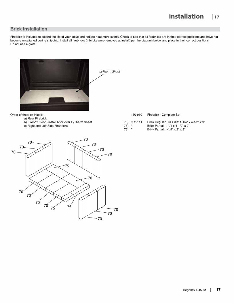
LyTherm Sheet
Order of firebrick install: a) Rear Firebrick b) Firebox Floor - install brick over LyTherm Sheet c) Right and Left Side Firebricks
Brick Installation
Firebrick is included to extend the life of your stove and radiate heat more evenly. Check to see that all firebricks are in their correct positions and have notbecome misaligned during shipping. Install all firebricks (if bricks were removed at install) per the diagram below and place in their correct positions.Do not use a grate.
180-960 Firebrick - Complete Set
70) 902-111 Brick Regular Full Size: 1-1/4" x 4-1/2" x 9"75) * Brick Partial: 1-1/4 x 4-1/2" x 2"76) * Brick Partial: 1-1/4" x 2" x 9"

18 | Regency I2450M
| 18 installation
Seasoned Wood
Whether you burn wood in a fireplace, stove or insert, good quality firewood is the key to convenience, efficiency and safety. Wet wood and pieces that are not the right size and shape for your wood burner can be frustrating, burn inefficiently and deposit creosote that can fuel a dangerous chimney fire. Good planning, seasoning and storage of the firewood supply are essential to successful wood burning.
• Stack the wood in separate rows in an open location where the summer sun can warm it and breezes can carry away the moisture. Do not stack unseasoned wood tightly in an unvented storage area.
• Do not allow firewood to lie on the ground for more than a couple of days before stacking. Mould and rot can set in quickly.• Stack the wood up off the ground on poles, lumber rails or pallets.• The top of the pile can be covered to keep off rain, but do not cover the sides.
Softer woods like pine, spruce and poplar/aspen that is cut, split and stacked properly in the early spring maybe be ready for burning in the fall. Extremely hard woods like oak and maple, and large pieces of firewood, may take a minimum of a full year to dry enough. Drying may also take longer in damp climates
There are a few ways to tell if wood is dry enough to burn efficiently. Use as many indicators as possible to judge the dryness of the firewood your are considering. Here are ways to judge firewood moisture.
• Using a moisture meter, select the species of fuel and then penetrate the pins into a split piece. Ideal moisture and seasoned firewood should be less than 20% moisture content.
• Checks or cracks in the end grain can be an indication of dryness, but may not be a reliable indicator. Some wet wood has checks and some dry wood has no checks.
• The wood tends to darken from white or cream colour to grey or yellow as it dries.• Two dry pieces banged together sound hollow; wet pieces sound solid and dull.• Dry wood weighs much less than wet wood.• Split a piece of wood. If the exposed surface feels damp, the wood is too wet to burn.

Regency I2450M | 19
19| operating instructions
WARNING: To build a fire in ignorance or to disregard the information contained in this section can cause serious per-manent damage to the unit and void your warranty!
Operating Instructions
With your unit now correctly installed and safety inspected by your local authority, you are now ready to start a fire. Before establishing your first fire, it is important that you fully understand the operation of your draft control.
Draft Control
Both the primary and air wash drafts are controlled by the control slide located on the front left side of the unit. To increase your draft - slide to the left to open, and to decrease - slide to the right to close. The I2450 unit has a secondary draft system that continually allows combustion air to the induction ports at the top of the firebox.
Draft is the force which moves air from the appli-ance up through the chimney. The amount of draft in your chimney depends on the length of the chimney, local geography, nearby obstructions and other factors. Too much draft may cause excessive temperatures in the appliance and may damage the unit. Inadequate draft may cause back puffing into the room and plugging of the chimney.
When your installation is completed and inspected you are ready for your first fire.
THIS UNIT IS DESIGNED TO BURN SEASONED CORDWOOD ONLY. COAL, BRIQUETTES AND ALL OTHERS LISTED ON PAGE 2 ARE NOT APPROVED. SEASONED CORDWOOD SHOULD BE LESS THAN 20% MOISTURE CONTENT.
START UP AND OPERATING PROCEDURES:
1. For the first few days, the stove will give off an odour from the paint. This is to be expected as the high temperature paint becomes seasoned. Windows and/or doors should be left open to provide adequate ventilation while this tem-porary condition exists. Burning the stove at a very high temperature the first few times may damage the paint. Burn fires at a moderate level the first few days.
2. Do not place anything on the stove top during the curing process. This may result in damage to your paint finish.
3. During the first few days it may be more difficult to start the fire. As you dry out your firebrick and your masonry flue, your draft will increase.
4. Open the air control to fully open position (all the way to the left) and open the front fuel door. Load firebox with 1.7lb of kindling and crumpled paper and light crumpled paper to establish fire. DO NOT USE A GRATE TO ELEVATE THE FIRE.
CAUTION: Never leave unit unattended if door is left open. This procedure is for fire start-up only, as unit may overheat if door is left open for too long.
5. Keep the door partially open for approximately 3 minutes and then close door.
WARNING: Never build a roaring fire in a cold wood insert. Always warm your wood insert up slowly!
6. Once most of the kindling has burned down, add more kindling and a few bigger pieces of startup wood split approximately 2 inches thick. Keep the door open until flames are reestablished.
7. When a good fire is established, add 8-10 more pieces of startup wood and close the door right away.
8. Once a nice coal bed is established and there are still good sized flames, the main larger logs can be loaded into the firebox. Rake the coals to create a uniform charcoal bed. Load 5 pieces of 17" long cord wood front to back,North/South orientation.
9. Once strong flames are established close the door.
10. After 20 minutes the fan can be set on high setting.
11. After 30 minutes the damper can be adjusted to
low or medium setting and the fan switched to the low setting.
12. For those units installed at higher elevations or
into sub-standard masonry fireplaces, drafting problems may occur. Consult an experienced dealer or mason on methods of increasing your draft.
13. Some cracking and popping noises may be experienced during the heating up process. These noises will be minimal when your unit reaches temperature.
14. Before opening your door to reload, open the air control fully for approximately 10 to 15 seconds until the fire has been re-established. This will minimize any smoking (spilling) back into the room. After loading wood and front door closed, close the air control to your desired setting only once the fire has been reestablished.
15. All fuel burning appliances consume oxygen during operation. It is important that you supply a source of fresh air to your unit while burning. A slightly opened window is sufficient for the purpose. If you also have a fireplace in your home, a downdraft may be created by your Regency Stove causing a draft down your chimney. If this occurs, slightly open a window near your unit.
WARNING: If the body of your unit, or any part of the chimney connector starts to glow, you are over firing. Stop loading fuel immediately and close the draft control until the glow has completely subsided.
16. If you have been burning your stove on a low draft, use caution when opening the door. After opening the damper, open the door a crack, and allow the fire to adjust before fully opening the door.
17. The controls of your unit or the air supply pas-sages should not be altered to increase firing for any reason.
18. If you burn the unit too slowly or at too low a set-ting your unit will not be operating as efficiently as it can. An easy rule of thumb says that if your glass is clean, then your flue is clean and your exhaust is clean. Burn the stove hot enough to keep your glass clean, you won't need to clean your flue as often.
First Fire
WARNINGFireplace Stoves equipped with doors should be operated only with doors fully closed. If doors are left partly open, gas and flame may be drawn out of the fireplace stove opening, creat-ing risks from both fire and smoke.
Left - Open Right - Closed
Outward - Open Inward - Closed
Side Draft Control
How to Light & Maintain a Wood Stove Fire

20 | Regency I2450M
| 20 operating instructions
Fan Operation
AutomaticTo operate the fan - turn on the rheostat.
This will allow the fan to turn on as the stove has come up to operating temperature. It will also shut the fan system off after the fire has gone out and the unit cooled to below a useful heat output range.
Operate the fan in the low speed position when burning in the LOW-MED LOW heat output ranges and operate in the high setting for MED-HIGH to HIGH heat outputs.
Route power cord to either left or right behind unit.
Ash Disposal
During constant use, ashes should be removed every few days.
Ashes should be placed in a metal container with a tight-fitting lid. The closed container of ashes should be placed on a noncombustible floor or on the ground, well away from all combustible materials, pending final disposal. If the ashes are disposed of by burial in soil or otherwise locally dispersed, they should be retained in the closed container until all cinders have thoroughly cooled.
Safety Precautions
1. Do not allow ashes to build up to the loading doors! Only remove ashes when the fire has died down. Even then, expect to find a few hot embers.
2. Please take care to prevent the build-up of ash around the start-up air housing located inside the stove box, under the loading door lip.
Safety Guidelines and Warnings
CAUTION: Do not use chemicals AS fluids to start fire.
1. CAUTION: Never use gasoline, gasoline type lantern fuels, kerosene, charcoal lighter fuel, or similar liquids to start or ‘freshen up’ a fire in your heater. Keep all such liquids well away from the heater while it is in use.
2. Keep the door closed during operation and maintain all seals in good condition.
3. Do not burn any quantities of paper, garbage, and never burn flammable fluids such as gasoline, naptha or engine oil in your stove.
4. If you have smoke detectors, prevent smoke spillage as this may set off a false alarm.
5. Do not overfire heater. If the chimney connector, flue baffle or the stove top begin to glow, you are over firing. Stop adding fuel and close the draft control. Over firing can cause extensive damage to your stove including warping and premature steel corrosion. Over firing will void your warranty.
6. Do not permit creosote or soot build-up in the chimney system. Check and clean chimney at regular intervals. Failure to do so can result in a serious chimney fire.
7. Your Regency stove can be very hot. You may be seriously burned if you touch the stove while it is operating, keep children, clothing and furniture away. Warn children of the burn hazard.
8. The stove consumes air while operating, provide adequate ventilation with an air duct or open a window while the stove is in use.
9. Do not connect this unit to a chimney flue serving another appliance.
10. Do not use grates or andirons or other methods for supporting fuel. Burn directly on the bricks.
11. Open the draft control fully for 10 to 15 seconds prior to slowly opening the door when refuelling the fire.
12. Do not connect your unit to any air distribution duct.
13. This heater is designed to burn natural wood only. Higher efficiencies and lower emissions generally result when burning air dried sea-soned hardwoods, as compared to softwoods or to green or freshly cut hardwoods.
14. In the event of component failure, replace parts with only Regency listed parts.
15. Warning: do not abuse glass door such as striking or slamming shut.
CAUTION: HOT WHILE IN OPERATION. KEEP CHILDREN, CLOTHING AND FURNITURE
AWAY. CONTACT MAY CAUSE SKIN BURNS.
16. Do not store any fuel closer than 2 feet from your unit. Do not place wood, paper, furniture, drapes or other combustibles near the appliance.
17. CAUTION: Do not operate with broken glazing.

Regency I2450M | 21
21| operating instructions
Creosote
When wood is burned slowly, it produces tar and other organic vapours combine with moisture to form creosote. The creosote vapours condense in the relatively cool chimney flue of a slow burning fire. As a result, creosote residue accumulates on the flue lining. When ignited, this creosote can result in an extremely hot fire.
The chimney connector and chimney should be inspected at least once every two months during the heating season to determine if creosote build up has occurred. If creosote has accumulated it should be removed to reduce the risk of chimney fire.
CAUTION: Things to remember in case of a chimney fire:
1. Close all draft and damper controls.
2. CALL THE FIRE DEPARTMENT.
Ways to Prevent and Keep Unit Free of Creosote
1. Burn stove with the draft control wide open for about 10-15 minutes every morning during burning season.
2. Burn stove with draft control wide open for about 10 - 15 minutes every time you apply fresh wood. This allows the wood to achieve the charcoal stage faster and burns up any unburned gas vapours which might otherwise be deposited within the system.
3. Only burn seasoned wood! Avoid burning kiln dried, wet or green wood. Seasoned wood has been dried at least one year.
4. A small hot fire is preferable to a large smoul-dering one that can deposit creosote within the system.
Wood Storage
Store wood under cover, such as in a shed, or cov-ered with a tarp, plastic, tar paper, sheets of scrap plywood, etc., as uncovered wood can absorb water from rain or snow, delaying the seasoning process.
Maintenance
It is very important to carefully maintain your fire-place stove, including burning seasoned wood and maintaining a clean stove and chimney system. Have the chimney cleaned before the burning season and as necessary during the season, as creosote deposits may build up rapidly. Moving parts of your stove require no lubrication.
5. The chimney and chimney connector should be inspected at least once every two months during the heating season to determine is a creosote buildup has occurred.
6. Have chimney system and unit cleaned by competent chimney sweeps twice a year during the first year of use and at least once a year thereafter or when a significant layer of creosote has accumulated (3 mm/1/8" or more) it should be removed to reduce the risk of a chimney fire.
Door Gasket
If the door gasket requires replacement, use a 7/8" gasket rope (Part #846-570). A proper high tem-perature gasket adhesive is required. See your Regency Dealer.The door catch may require adjustment as the door gasket compresses after a few fires. The door latch compression may require adjustment to renew seal. Removal of a shim, (see section in this manual), will allow the latch to be moved closer to the door frame, causing a tighter seal.
Glass Maintenance
Your Regency stove is supplied with 5mm Neoceram ceramic glass (Part #846-308) that will withstand the highest heat that your unit will produce. In the event that you break your glass by impact, purchase your replacement from an authorized Regency dealer only, and follow our step-by-step instructions for replacement (refer to Glass Replacement section).
Allow the stove to cool down before cleaning the glass. Cleaning the glass will prevent build up of carbon and allow full view of the fire.
WARNING: Do not clean the glass when it is hot.
WARNING: Do not use abrasive cleaners, a damp cloth and glass cleaner is effective.
Latch Adjustment
The door latch may require adjustment as the door gasket material compresses after a few fires. Re-moval of the spacer washer, shown in the diagram below, will allow the latch to be moved closer to the door frame, causing a tighter seal. Remove and replace the nuts, washer and spacer as shown.
Removing Wooden Handle
1. To remove the wooden door handle from unit, firstly locate 7/64” Allen key hole at the bottom of wooden handle.
2. Unscrew 7/64” Allen Key screw counterclock-wise. Once the screw is completely loose, re-move and drop the handle down off the door handle shaft and replace with new handle.

22 | Regency I2450M
| 22 maintenance
Cleaning & Maintaining Your Wood Stove
CAUTION: DO NOT CONNECT TO, OR USE IN CONJUNCTION WITH ANY AIR DISTRIBUTION DUCT WORK
UNLESS SPECIFICALLY APPROVED FOR SUCH INSTALLATION.
CAUTION: DO NOT BURN GARBAGE OR FLAMMABLE LIQUIDS SUCH AS
GASOLINE, NAPTHA OR ENGINE OIL. SOME FUELS COULD GENER-ATE CARBON MONOXIDE AND ARE
VERY DANGEROUS.
DO NOT BURN: • Treated wood • Coal • Garbage • Cardboard • Solvents • Colored Paper • Trash • Salt drift wood • Cut lumber, plywood, mill ends.
Burning treated wood, garbage, solvents, colored paper or trash may result in release of toxic fumes. Burning coal, cardboard, or loose paper can produce soot, or large flakes of char or fly ash, causing smoke spillage into the room.

Regency I2450M | 23
23| maintenance
Vertical Stainless Deflector Replacement
1. Remove 2 front secondary air tubes / vermiculite baffles as per page 15.
2. Loosen the two 7/16'' bolts + nuts to remove / replace vertical deflector.
3. Repeat steps to install new vertical deflector.
NOTE: ENSURE THAT VERTICAL DEFLECTOR IS PUSHED UP AS FAR AS POSSIBLE. TIGHT TO TOP OF FIREBOX.
Note that the unit is not exactly as shown.
7/16'' Nuts7/16'' Bolts
Vertical Deflector
Remove 2 front air tubes
Slide right + down to remove. Reverse to replace.

24 | Regency I2450M
| 24 maintenance
Annual Maintenance
Completely clean out entire unit Annually
Inspect air tube and bricks Replace any damaged parts.
Adjust door catch assembly If unable to obtain a tight seal on the door - replace door gasket seal.Readjust door catch after new gasket installed.
Inspect condition and seal of: Glass Gasket Door Gasket Perform paper test - replace gasket if required
Paper Test Test the seal on the loading door with a paper bill. Place a paper bill in the gasket area of the door on a cold stove.Close the door. Try to remove the paper by pulling. The paper should not pull out easily, if it does, try adjusting the door latch, if that doesn't solve the problem replace the door gasket.
Check and lubricate door hinge + latch Use only high temperature anti seize lube. (ie. never seize)
Check glass for cracks Replace if required.
Clean blower motor Disconnect power supply.Remove and clean blower.*DO NOT LUBRICATE*
Inspect and clean chimney Annual professional chimney cleaning recommended.
NOTE:Chimney CleaningWhen cleaning the chimney system the air tubes, baffles should be removed for ease of cleaning. See manual for details on removal. We highly recommend that the chimney cleaning be done by a professional as they will have the necessary tools such as a proper sized brush and special vacuum cleaner designed to deal with fine particles.

Regency I2450M | 25
25| parts list
Main Assembly & Options - I2450M
Part # Description
23) 142-917 Fan Assembly24) 910-157/P Fan Motor 120 Volts* 910-678 Power Cord 120 Volts27) 910-142 Fan Thermodisc28) 910-140 Fan Speed Hi / OFF / Low
Switch (3-way)29) 910-138 Auto / Manual On / OFF Switch30) * Grommet Strain Relief36) 033-953 Air Tube 3/4" (Qty:4) (each)37) 020-957 Baffle (2/set)
Part # Description
42) 163-931 Convection Grill - Nickel (Opt) 163-930 Convection Grill - Blk43) * Hex Nut 10-24 Zinc Coated44) * Washer #10 Flat45) * Bolt, 10-24 x 3/4" Blk CarriageN/S 181-085/P Vertical Stainless DeflectorN/S 021-022 Firebox Floor Gasket
948-223 Regency Logo - Nickel 920-082 Manual
*Not available as a replacement part.
DETAIL M24
28
29
42
7
23
20
1
18
36
37
22
21
42
2
4
9
17
16
19
6
27
Part # Description
1) 850-251 Door Assy - Large Black 850-253 Door Assy - Large Nickel Accent 2) 846-308 Glass - Replacement4) 936-241 7/8" Adhesive Tape Gasket6) 904-115* Screw 1/4-20 x 3/8"7) 181-034F Glass Retainer - Large9) 021-973 Door Handle Assembly
16) 846-570 Door Gasket Kit17) 948-079BN Hinge Caps - Nickel (each)17) 846-918 Hinge Caps Black Oxide (Set of 2)18) 021-018 Smoke Detector19) 650-084 Door Spacer20) 948-146 Wood Handle 21) 181-039 Draft Control Handle22) 181-632/P Flue Adaptor

26 | Regency I2450M
| 26 parts list
Faceplates - I2450M
Part # Description
140-911 Faceplate & Trim Set - Regular 180-570 Black Trim Regular (set of 3)285) * Trim Right Regular286) * Trim Top Regular287) * Trim Left Regular288) * Faceplate Side Regular289) * Faceplate Top Regular
140-913 Faceplate & Trim Set - Oversize 180-572 Black Trim Oversize (set of 3)295) * Trim Right Oversize296) * Trim Top Oversize297) * Trim Left Oversize298) * Faceplate Side Oversize299) * Faceplate Top Oversize
*Not available as a replacement part.
285
286
287
288
288
289
REGULAR
296
295
297
298
299
298
OVERSIZE

Regency I2450M | 27
27| parts list
Brick Panels - I2450M
Part # Description 180-960 Firebrick - Complete Set
70) 902-111 Brick Regular Full Size: 1-1/4" x 4-1/2" x 9"75) * Brick Partial: 1-1/4 x 4-1/2" x 2"76) * Brick Partial: 1-1/4" x 2" x 9"

28 | Regency I2450M
| 28 warranty
Revision Date: July 2019 Regency Wood Products Warranty
Limited Lifetime Warranty FPI Fireplace Products International Ltd. (for Canadian customers) and Fireplace Products U.S., Inc. (for U.S. customers) (collectively referred to herein as “FPI”) extends this Limited Lifetime Warranty to the original purchaser of this appliance provided the product remains in the original place of installation. The items covered by this limited warranty and the period of such coverage is set forth in the table below. Some conditions apply (see below). The policy is not transferable, amendable, or negotiable under any circumstances.
Wood Products
Component Coverage
Labor Coverage
Components Covered Limited Lifetime
5 years
2 years
1 year Warranty (Years)
Welded Firebox Steel 5 All Stainless Steel Components, Smoke Deflectors, Heat Shields etc.
3
Air Tubes 3 Airmate 3 Door handle and latch assembly, all hardware 3 Glass Thermal Breakage Only 3 Steel Faceplates, Accessory Housings 3 All Plating 3 Ash Drawer, Heatshields, Pedestal All Baffles, Steel, Ceramic, Vermiculite C-Baffles All castings, firebox, surrounds, doors, panels etc. 3 All Electrical, Blower, wiring, switches etc. 2 Glass - Crazing 1 Catalyst Combustor *10
Years Prorated
Venting/Chimney 1 Screens 1
*See specific warranty details in regards to the catalyst combustor in unit manual. Conditions: Warranty protects against defect in manufacture or FPI factory assembled components only, unless herein specified otherwise. Any part(s) found to be defective during the warranty period as outlined above will be repaired or replaced at FPI’s option through an accredited distributor, dealer or pre-approved and assigned agent provided that the defective part is returned to the distributor, dealer or agent for inspection if requested by FPI. Alternatively, FPI may at its own discretion fully discharge all of its obligations under the warranty by refunding the verified purchase price of the product to the original purchaser. The purchase price must be confirmed by the original Bill of Sale. The authorized selling dealer, or an alternative authorized FPI dealer if pre-approved by FPI, is responsible for all in-field diagnosis and service work related to all warranty claims. FPI is not responsible for results or costs of workmanship of unauthorized FPI dealers or agents in the negligence of their service work. At all times FPI reserves the right to inspect reported complaints on location in the field claimed to be defective prior to processing or authorizing of any claim. Failure to allow this upon request will void the warranty.

Regency I2450M | 29
29| warranty
Revision Date: July 2019 Regency Wood Products Warranty
All warranty claims must be submitted by the dealer servicing the claim, including a copy of the Bill of Sale (proof of purchase by you). All claims must be complete and provide full details as requested by FPI to receive consideration for evaluation. Incomplete claims may be rejected. Replacement units are limited to one per warranty term. Airtube and baffle replacements are limited to one replacement per term. Unit must be installed according to all manufacturers’ instructions as per the manual. All Local and National required codes must be met. The installer is responsible to ensure the unit is operating as designed at the time of installation. The original purchaser is responsible for annual maintenance of the unit, as outlined in the owner’s manual. As outlined below, the warranty may be voided due to problems caused by lack of maintenance. Repair/replacement parts purchased by the consumer from FPI after the original coverage has expired on the unit will carry a 90 day warranty, valid with a receipt only. Any item shown to be defective will be repaired or replaced at our discretion. No labor coverage is included with these parts. Exclusions: This Limited Lifetime Warranty does not extend to rust or corrosion of any kind due to: a lack of maintenance or improper venting, lack of combustion air provision, or exposure to corrosive chemicals (i.e. chlorine, salt, air, etc.). This Limited Lifetime Warranty also does not extend to: paint, firebricks (rear, sides, or bottom), door gasketing, glass gasketing (or any other additional factory fitted gasketing), vermiculite floor bricks, andiron assemblies, and flue damper rods. Malfunction, damage or performance based issues as a result of environmental conditions, location, chemical damages, downdrafts, installation error, installation by an unqualified installer, incorrect chimney components (including but not limited to cap size or type), operator error, abuse, misuse, use of improper fuels (such as unseasoned cordwood, mill-ends, construction lumber or debris, off-cuts, treated or painted lumber, metal or foil, plastics, garbage, solvents, cardboard, coal or coal products, oil based products, waxed cartons, compressed pre-manufactured logs, kiln dried wood), lack of regular maintenance and upkeep, acts of God, weather related problems from hurricanes, tornados, earthquakes, floods, lightning strikes/bolts or acts of terrorism or war, which result in malfunction of the appliance are not covered under the terms of this Limited Lifetime Warranty. FPI has no obligation to enhance or modify any unit once manufactured (i.e. as products evolve, field modifications or upgrades will not be performed on existing appliances). This warranty does not cover dealer travel costs for diagnostic or service work. All labor rates paid to authorized dealers are subsidized, pre-determined rates. Dealers may charge homeowner for travel and additional time beyond their subsidy. Any unit showing signs of neglect or misuse will not be covered under the terms of this warranty policy and may void this warranty. This includes units with rusted or corroded fireboxes which have not been reported as rusted or corroded within three (3) months of installation/purchase. Units which show evidence of being operated while damaged, or with problems known to the purchaser and causing further damages will void this warranty. Units where the serial no. has been altered, deleted, removed or made illegible will void this warranty. Minor movement, expansion and contraction of the steel is normal and is not covered under the terms of this warranty. FPI is not liable for the removal or replacement of facings or finishing in order to repair or replace any appliance in the field. Freight damages for products or parts are not covered under the terms of the warranty. Products made or provided by other manufacturers and used in conjunction with the FPI appliance without prior authorization from FPI may void this warranty.

30 | Regency I2450M
| 30 warranty
Revision Date: July 2019 Regency Wood Products Warranty
Limitations of Liability: The original purchaser’s exclusive remedy under this warranty, and FPI’s sole obligation under this warranty, express or implied, in contract or in tort, shall be limited to replacement, repair, or refund, as outlined above. IN NO EVENT WILL FPI BE LIABLE UNDER THIS WARRANTY FOR ANY INCIDENTAL OR CONSEQUENTIAL COMMERCIAL DAMAGES OR DAMAGES TO PROPERTY. TO THE EXTENT PERMITTED BY APPLICABLE LAW, FPI MAKES NO EXPRESS WARRANTIES OTHER THAN THE WARRANTY SPECIFIED HEREIN. THE DURATION OF ANY IMPLIED WARRANTY IS LIMITED TO DURATION OF THE EXPRESSED WARRANTY SPECIFIED ABOVE. IF IMPLIED WARRANTIES CANNOT BE DISCLAIMED, THEN SUCH WARRANTIES ARE LIMITED IN DURATION TO THE DURATION OF THIS WARRANTY. Some U.S. states do not allow limitations on how long an implied warranty lasts, or allow exclusion or limitation of incidental or consequential damages, so the above limitations or exclusions may not apply to you. Customers located outside the U.S. should consult their local, provincial or national legal codes for additional terms which may be applicable to this warranty. How to Obtain Warranty Service: Customers should contact the authorized selling dealer to obtain all warranty and service. In the event the authorized selling dealer is unable to provide warranty / service, please contact FPI by mail at the address listed on the next page. Please include a brief description of the problem and your address, email and telephone contact information. A representative will contact you to make arrangements for an inspection and/or warranty service, by an alternative dealer. Product Registration and Customer Support: Thank you for choosing a Regency Fireplace. Regency strives to be a world leader in the design, manufacture, and marketing of hearth products. To provide the best support for your product, we request that you complete a product registration form at http://www.regency-fire.com/Customer-Care/Warranty-Registration.aspx within ninety (90) days of purchase.

Regency I2450M | 31
31| warranty
Product Registration and Customer Support:
Thank you for choosing a Regency Fireplace. Regency strives to be a world leader in the design, manufacture, and marketing of hearth products. To provide the best support for your product, we request that you complete a product registration form found on our Web Site under Customer Care within ninety (90) days of purchase.
For purchases made in CANADA or the UNITED STATES: http://www.regency-fire.com/Customer-Care/Warranty-Registration.aspx
For purchases made in AUSTRALIA: http://www.regency-fire.com.au/Customer-Care/Warranty-Registration.aspx
You may also complete the warranty registration form below to register your Regency Fireplace Product and mail and/or fax it back to us, and we will register the warranty for you. It is important you provide us with all the information below in order for us to serve you better.
Warranty Registration Form (or Register online immediately at the above Web Site):
Warranty Details
Serial Number (required):
Purchase Date (required) (mm/dd/yyyy):
Product Details
Product Model (required):
Dealer Details
Dealer Name (required):
Dealer Address:
Dealer Phone #:
Installer:
Date Installed (mm/dd/yyyy):
Your Contact Details (required)
Name:
Address:
Phone:
Email:
For purchases made in CANADA:
FPI Fireplace Products International Ltd. 6988 Venture St. Delta, British Columbia Canada, V4G 1H4
Phone: 604-946-5155 Fax: 1-866-393-2806
For purchases made in the UNITED STATES:
Fireplace Products US, Inc. PO Box 2189 PMB 125 Blaine, WA United States, 98231
Phone: 604-946-5155 Fax: 1-866-393-2806
For purchases made in AUSTRALIA:
Fireplace Products Australia Pty Ltd 1- 3 Conquest WayHallam, VICAustralia, 3803
Phone: +61 3 9799 7277 Fax: +61 3 9799 7822
For fireplace care and tips and answers to most common questions please visit our Customer Care section on our Web Site. Please feel free to contact your selling dealer if you have any questions about your Regency product.

32 | Regency I2450M
| 32

Regency I2450M | 33
33| notes

34 | Regency I2450M
| 34 notes


Printed in CanadaRegency and Classic are trademarks of FPI Fireplace Products International Ltd.
© Copyright 2021, FPI Fireplace Products International Ltd. All rights reserved.
Installer: Please complete the following information
Dealer Name & Address: ______________________________________________
___________________________________________________________________
Installer: ___________________________________________________________
Phone #: ___________________________________________________________
Date Installed: ______________________________________________________
Serial #: ____________________________________________________________