Owner's Manuald3f8w3yx9w99q2.cloudfront.net/1380/Stamina-Gravity-Inversion-Table/...Read all...
18
55-1538 STAMINA PRODUCTS MADE IN CHINA Product May Vary Slightly From Pictured. CAUTION: 1. Weight on this product should not exceed 300 lbs. 2. Class H equipment: This equipment is for home use only. It is not for commercial use. ! WARNING ! Exercise can present a health risk. Consult a physician before beginning any exercise program with this equipment. If you feel faint or dizzy, immediately discontinue use of this equipment. Serious bodily injury can occur if this equipment is not assembled and used correctly. Serious bodily injury can also occur if all instructions are not followed. Keep others and pets away from equipment when in use. Always make sure all bolts and nuts are tightened prior to each use. Follow all safety instructions in this manual. When calling for parts or service, please specify the following number. 2005, 12 2040 N. Alliance, Springfield, MO 65803 Customer Service Number 1 (800) 375-7520 www.staminaproducts.com This Product is Produced Exclusively by 2005 Stamina Products, Inc. Owner's Manual
-
Upload
duongkhuong -
Category
Documents
-
view
218 -
download
2
Transcript of Owner's Manuald3f8w3yx9w99q2.cloudfront.net/1380/Stamina-Gravity-Inversion-Table/...Read all...

55-1538STAMINA PRODUCTS
MADE IN CHINA
Product May Vary SlightlyFrom Pictured.
CAUTION: 1. Weight on this product should not exceed 300 lbs. 2. Class H equipment: This equipment is for home
use only. It is not for commercial use.
! WARNING !
Exercise can present a healthrisk. Consult a physicianbefore beginning any exerciseprogram with this equipment.If you feel faint or dizzy,immediately discontinue useof this equipment. Seriousbodily injury can occur if thisequipment is not assembledand used correctly. Seriousbodily injury can also occur ifall instructions are notfollowed. Keep others andpets away from equipmentwhen in use. Always makesure all bolts and nuts aretightened prior to each use.Follow all safety instructions inthis manual.
When calling for parts orservice, please specify thefollowing number.
2005, 12
2040 N. Alliance, Springfield, MO 65803Customer Service Number
1 (800) 375-7520www.staminaproducts.com
This Product is Produced Exclusively by
2005 Stamina Products, Inc.
Owner's Manual

2
SAFETY INSTRUCTIONS
2
WARNING:
1.2.3.4.
5.
6.
7.8.
9.10.
11.12.13.14.15.16.17.
18.19.20.
21.
Read all warnings posted on the Gravity Inversion Table.The Gravity Inversion Table should only be used after a thorough review of the Owner's Manual.We recommend that two people be available for assembly of this product.Do not use the Gravity Inversion Table alone. Always have a helper available in case assistance is neededin recovering from the decline position.Verify that adequate head clearance is available between the user's head and the floor before using thisinversion table. This is especially important for tall users.Make sure that the Pivot Arms are assembled using the same hole on both Pivot Arms. Pay close attention toSteps 3 and 4 on page 7.Make sure that the Pivot Arms are always secured to the pegs on the Main Frame with the Bolts and Washers.Adjust the Nylon Straps to an angle of 15 to 20 degrees and use this setting until you have verified your heightsetting and become familiar with the Gravity Inversion Table.Use the lowest holes in the Pivot Arms until you become familiar with the Gravity Inversion Table.You must understand how to recover from the fully inverted position before using the fully inverted position.Read the RECOVERY FROM LOCKED POSITION section at the bottom of page 12 BEFORE using the fullyinverted position.Do not allow children to use or play on the Gravity Inversion Table.Keep small children and pets away from the Gravity Inversion Table at all times.The Gravity Inversion Table should not be used by persons weighing more than 300 lbs.The Gravity Inversion Table should not be used by persons over 6 feet 6 inches tall.It is recommended that you place this exercise equipment on an equipment mat.Use the Gravity Inversion Table only on a level surface.Wear appropriate clothing when exercising; do not wear loose clothing that could become caught in the GravityInversion Table.Be sure that there is enough room for the bed to rotate completely.Use the Gravity Inversion Table only as described in the manual.The safety level of the Gravity Inversion Table can be maintained only if it is examined regularly for damageand wear.This equipment is for home use only. It is not for commercial use.
Maintenance Instructions 13Product Parts Drawing 14Parts List 15Warranty 16Notes 17Fax/Mail Ordering Form 18
Safety Instructions 2Before You Begin 4Hardware Identification Chart 5Assembly Instructions 6Operational Instructions 10Storage 13
TABLE OF CONTENTS Page Page
Extreme obesityGlaucoma, retinal detachment or conjunctivitisPregnancySpinal injury, Cerebral Sclerosis, or acutely swollen jointsMiddle ear infectionHigh blood pressure, Hypertension, Recent stroke or Transient ischemic attackHeart or circulatory disorders for which you are being treatedHiatus hernia or Ventral herniaBone weaknesses including Osteoporosis, Unhealed fractures, Medullary pins, orSurgically implanted orthopedic supports.Use of anti-coagulants including Aspirin in high doses.
WARNING: Before using this equipment you should consult with your personal physician to see if inversionequipment is appropriate for you. Do not use this equipment without your physician's approval. Do not usethis equipment if you have any of the following conditions or ailments:
To reduce the risk of serious injury, read the following safety instructions beforeusing the Gravity Inversion Table.

THANK YOU FOR PURCHASING THEGravity Inversion Table
To help you get started, we have pre-assembled most of yourGravity Inversion Table at the factory with the exception
of those few parts left unassembled for shipping purposes.Simply follow the few assembly instructions set forth in this manual.
Within a few minutes you will be getting your body into shape and on yourway to achieving a happier and healthier lifestyle.
Should you have any questions,please call our Customer Service Department toll-free number,
1 (800) 375-7520Monday - Friday, 8:00 A.M. - 5:00 P.M., Central Time.
CALL US FIRST
3

Thank you for choosing the Gravity InversionTable. We take great pride in producing this qualityproduct and hope it will provide many hours of qualityexercise to make you feel better, look better and enjoylife to its fullest. Yes, it's a proven fact that a regular exerciseprogram can improve your physical and mentalhealth. Too often, our busy lifestyles limit our timeand opportunity to exercise. The Gravity InversionTable provides a convenient and simple method tobegin your assault on getting your body in shape andachieving a happier and healthier lifestyle. Before reading further, please review the drawingbelow and familiarize yourself with the parts that arelabeled. For your benefit, read this manual carefully beforeusing the Gravity Inversion Table.
BEFORE YOU BEGIN
4
Pivot Arm
Bumper
Footrest
Heel Holder
HeightAdjustment Beam
Front Frame
Main Frame
Buckle Strap
Hand Grip
Rear Frame
Although Stamina tries to manufacture its productswith the finest materials and uses the higheststandards of manufacturing, occasionally a part thatdoes not fit, is the incorrect size, or is otherwiseinappropriate is found. Even with the highestinspection and quality controls in place these thingswill happen occasionally. Please do not return theproduct. For your convenience, Stamina has aCustomer Service Department with a toll-freenumber. If a part is missing, does not fit, is theincorrect size, or is otherwise inappropriate, pleasecall 1 (800) 375-7520 (in the U.S.) between 8:00 A.M.and 5:00 P.M. Central Time, Monday through Friday.Our operators will be able to assist you with yourproblem and the parts will be mailed directly to yourhouse.
Adjustment Knob
EndcapStand
THE FOLLOWING TOOLS ARE INCLUDED FOR ASSEMBLY : Wrench
Combination Wrench
Protective Cover
Nylon Bed
Protective Cover

5
Part No. and Description Qty
HARDWARE IDENTIFICATION CHAT
Place washers, the end of bolts or screws on the circles to check for thecorrect size. Use the small scale to check the sizes of bolts and screws.
This chart is provided to help identify the hardware used in the assembly process.After unpacking the unit, open the hardware bag and make sure that you have the following items:
length
length
mm.
in.
INCHES
MILLIMETERS
11/20 21/2 31/2 41/2 51/2 61/2
0 10 20 30 40 50 60 70 80 90 100 110 120 130 140 150
6 8 10 12
3/16" 5/16" 1/2"3/8"1/4"
NOTICE: The length of all kinds of screws and bolts are not includedthemselves head, except the flat head screws and bolts.
42 Nylock Nut (M6 x 1) 2
38 Bolt, Round Head (M6 x 1 x 10mm) 2
40 Bolt, Hex Head (M6 x 1 x 47mm) 2
44 Larger Washer (M6) 245 Washer (M6) 4
1. Some of the hardware items listed may be attached to other parts.2. Bolt length is measured from the bottom of the bolt head to the end of the bolt.
NOTE:

ASSEMBLY INSTRUCTIONS
Place all parts from the box in a cleared area and position them on the floor in front of you. Remove allpacking materials from your area and place them back into the box. Do not dispose of the packing materialsuntil assembly is completed. Read each step carefully before beginning. If you are missing a part pleasecall our toll-free number for assistance 1 (800) 375-7520 or e-mail us at:
6
STEP 1Unfold the BASE ASSEMBLY to an upright position by moving the FRONT FRAME(1) away from REARFRAME(2). Then push down on the middle of the two FOLDING LINKAGES(3) until they are fullylocked down.
STEP 2Slide one PROTECTIVE COVER(23) onto each side of the BASE ASSEMBLY, and pull the coversdown until the bottom of the covers are slightly lower than the FOLDING LINKAGES(3). Secure thePROTECTIVE COVERS(23) to the FOLDING LINKAGES(3) with the SECURING STRAPS on thebottom of the covers.NOTE: When the PROTECTIVE COVERS(23) are assembled correctly, the FOLDING LINKAGES(3)
should not be visible. Refer to the illustration.
ASSEMBLY INSTRUCTIONS
7
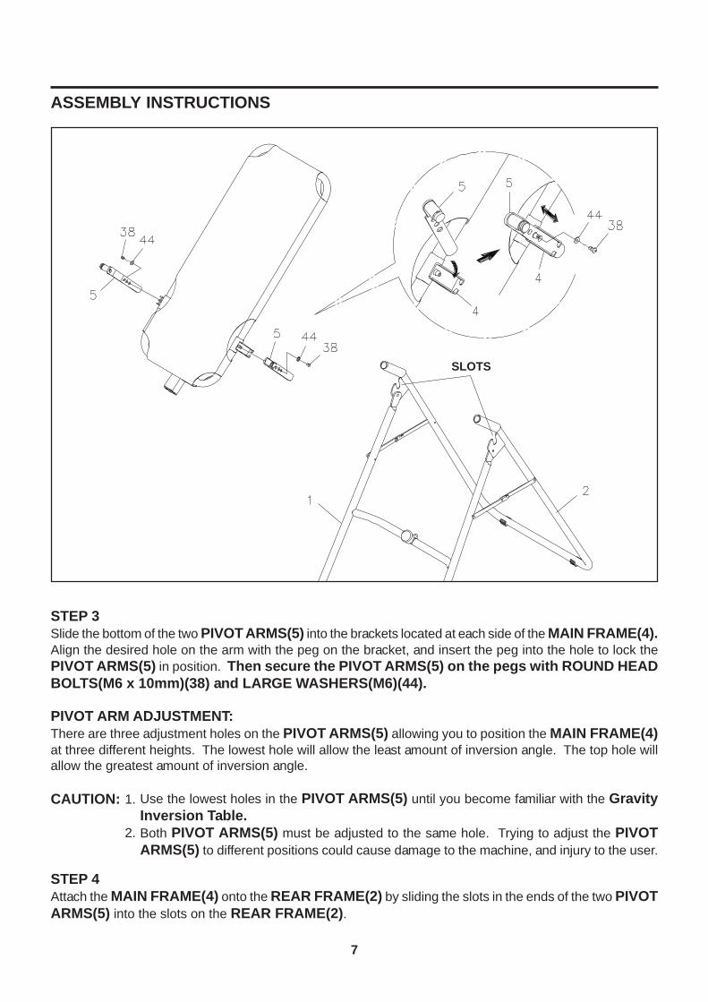
STEP 3Slide the bottom of the two PIVOT ARMS(5) into the brackets located at each side of the MAIN FRAME(4).Align the desired hole on the arm with the peg on the bracket, and insert the peg into the hole to lock thePIVOT ARMS(5) in position. Then secure the PIVOT ARMS(5) on the pegs with ROUND HEADBOLTS(M6 x 10mm)(38) and LARGE WASHERS(M6)(44).
PIVOT ARM ADJUSTMENT:There are three adjustment holes on the PIVOT ARMS(5) allowing you to position the MAIN FRAME(4)at three different heights. The lowest hole will allow the least amount of inversion angle. The top hole willallow the greatest amount of inversion angle.
CAUTION:
STEP 4Attach the MAIN FRAME(4) onto the REAR FRAME(2) by sliding the slots in the ends of the two PIVOTARMS(5) into the slots on the REAR FRAME(2).
Use the lowest holes in the PIVOT ARMS(5) until you become familiar with the GravityInversion Table.Both PIVOT ARMS(5) must be adjusted to the same hole. Trying to adjust the PIVOTARMS(5) to different positions could cause damage to the machine, and injury to the user.
1.
2.
SLOTS

ASSEMBLY INSTRUCTIONS
8
STEP 5Attach the FOOTREST(8) onto the HEIGHT ADJUSTMENT BEAM(6) with the ADJUSTMENTKNOB(9).NOTE:
STEP 6: Insert the PAD TUBE(10) through the hole on the HEIGHT ADJUSTMENT BEAM(6) andsecure with HEX BOLT(M6 x 47mm)(40), NYLOCK NUT(M6)(42), and WASHERS(M6)(45). Placea HEEL HOLDER BRACKET(11) onto a HEEL HOLDER(12), then slide them onto PAD TUBE(10)together. Slide another set of HEEL HOLDER BRACKET(11) and HEEL HOLDER(12) over the otherend of the PAD TUBE(10).
STEP 7: Attach the ADJUSTABLE INSTEP FRAME(7) to the HEIGHT ADJUSTMENT BEAM(6)by pulling the SMALL SPRING PIN(15) and sliding the ADJUSTABLE INSTEP FRAME(7) completelyinto the HEIGHT ADJUSTMENT BEAM(6). Place a WASHER(M6)(45) onto the HEX BOLT(M6 x 47mm)(40), then insert the bolt the halfway through the square tube on the HEIGHT ADJUSTMENTBEAM(6), slide the bolt through the ring at the bottom of the SPRING(13), slide the bolt through thesquare tube and secure with NYLOCK NUT(M6)(42) and WASHER(M6)(45). Press the SQUAREPLUG(35) into the HEIGHT ADJUSTMENT BEAM(6). Install a HEEL HOLDER BRACKET(11)and HEEL HOLDER(12) onto both sides of the ADJUSTABLE INSTEP FRAME(7).
The four adjustment holes in the FOOTREST(8) allow the FOOTREST(8) to be attached in fourdifferent positions. Start with one of the center positions and adjust if necessary. Use the outerposition if users are taller than average. Use the inner position if users are shorter than average.

ASSEMBLY INSTRUCTIONS
9
1.
2.
STEP 8Install the HEIGHT ADJUSTMENT BEAM(6) into MAIN FRAME(4) by pulling the LARGE SPRINGPIN(18) on the MAIN FRAME(4) and inserting the HEIGHT ADJUSTMENT BEAM(6) as shown. Foradded safety, thread the LOCKING KNOB(19) into back side of the MAIN FRAME(4).WARNING:
STEP 9Attach the NYLON STRAP(27) onto the BUCKLE on the end of the BUCKLE STRAP(28) by insertingthe end of the strap up through the bottom of the buckle, as shown in the illustration 1.
STEP 10Hook the end of the NYLON STRAP(27) onto the loop on the back of the MAIN FRAME(4). Hook theend of the BUCKLE STRAP(28) onto the loop on the FRONT FRAME(1).NOTE:
A.
C.
B.
BUCKLE
Do not use the Gravity Inversion Table until you have verified your height setting. Failureto use the proper height setting can result in difficulty recovering from the decline position.See HEIGHT ADJUSTMENT instructions on page 10.
The NYLON STRAPS are used to control the decline angle of the Gravity Inversion Table.For a steeper decline angle, lengthen the straps. For a lessor decline angle, shorten the straps.Make sure these NYLON STRAPS are tight in the buckle and check the decline angle beforeusing the Gravity Inversion Table.

OPERATIONAL INSTRUCTIONS
10
GENERAL PRECAUTIONSUse the lowest holes in the PIVOT ARMS(5) until you become familiar with the Gravity Inversion Table.Do not use the Gravity Inversion Table alone. Always have a helper available in case assistance isneeded in recovering from the decline position.Make sure that the HEEL HOLDERS(12) are holding your feet securely.Make sure that the HEIGHT ADJUSTMENT BEAM(6) is properly set for your height.Make sure that the HEIGHT ADJUSTMENT BEAM(6) is held securely by both the LARGE SPRINGPIN(18) and the LOCKING KNOB(19).Make sure that there is enough room for the bed to rotate completely.
1.2.
3.4.5.
6.
THE HANDLEBARSFor added convenience, and safety, a set of HANDLEBARS has been added to the Gravity InversionTable. These HANDLEBARS are located at the top of the REAR FRAME(2). The HANDLEBARS are tohelp you return to the upright position from any degree of inversion. If you wish to return to the uprightposition, and the bed is moving too slowly, or not moving at all, simply grab the HANDLEBARS and pull onthem until you return to the upright position.
HEIGHT ADJUSTMENTThe Gravity Inversion Table is a very sensitive balance device. It responds to very slight changes inweight distribution. It is very important to make sure that the height adjustment is adjusted properly. Usethe following procedure to set the height adjustment and balance the Gravity Inversion Table.
Adjust the NYLON STRAPS to restrictmovement to approximately 15 degreesbeyond the horizontal position. Thenylon straps should not allow the GravityInversion Table to go into the full inversionposition while you are setting the heightadjustment.Loosen the LOCKING KNOB(19) underthe MAIN FRAME(4).Pull the LARGE SPRING PIN(18) and usethe SCALE DECAL(16) to set theHEIGHT ADJUSTMENT BEAM(6).Tighten the LOCKING KNOB(19).Mount the machine.Lock your ankles into the HEELHOLDERS(12).Lie back with your hands at your sides.Slowly raise your hands to your chest.If your feet are higher than your head,dismount and try a taller setting. If you donot rotate to a position close to level,dismount and try a shorter setting.
3.
4.5.
1.
2.
6.
7.8.9.
The Gravity Inversion Table should return to the upright position when your hands are belowyour waist. If it does not, use a taller setting.Verify that adequate head clearance is available between the user's head and the floor beforeusing this inversion table. This is especially important for tall users.
NOTE: 1.
2.
Handlebars

OPERATIONAL INSTRUCTIONS
11
Start by lying fully back on the bed with your hands at your side, or resting on your thighs.Keeping your hands close to your body begin to raise your arms slowly allowing the table to rotatebackward. Stop, or lower your arms to control the downward rotation of the table.Raise your arms until they are over your head. At this point, the inversion table will be as far back as itcan go.As you get more comfortable with the use, rock the bed slowly by moving your arms up and down slowly.A gentle swinging motion will alternately put your spine in traction and compression. This rhythmic typeof traction is used by many hospitals and doctors to treat certain back problems.It is recommended that the inversion table be used for five or ten minutes each morning, and again eachevening.Return to the upright position by slowly moving your hands back down to your thighs.
USING THE INVERSION TABLE1.2.
3.
4.5.
6.
7.
3.1.
4.2.

OPERATIONAL INSTRUCTIONS
12
Begin slowly: Invert only 15-20 degrees to begin with. Stay inverted only as long as you are comfortable.Return upright slowly.Make gradual changes: Increase the angle only if it is comfortable. Increase the angle only a fewdegrees at a time. Increase the time of use 1-2 minutes up to ten over a period of weeks. Add stretchingand light exercise only after you are comfortable with inversion.Watch your body: Come up slowly, dizziness after a session means you came up to fast. Wait a whileafter eating before using table. If you get nauseous, do not fight it, come up as soon as you feel queasy.Keep moving: Movement while inverted encourages blood, lymph, and spinal fluid circulation and aidsin alignment of bones and organs. Movement may be accomplished by either rhythmic traction or lightexercise. Do not exercise strenuously while inverted. Limit partial inversion without movement to one ortwo minutes. Limit full inversion with no movement to only a few seconds.Invert regularly: We recommend two or three times a day depending upon your current condition. Try toschedule it for the same times each day.
SUGGESTIONS FOR USE1.
2.
3.
4.
5.
A. B. C.
LOCKING THE BEDWhen the inversion table rotates past the vertical inverted position the bed becomes locked, and will notreturn to the upright position in the usual way. The locked position allows you to hang straight upside-downcompletely free of the bed. This position allows you to enjoy all of the benefits of a handstand, with none ofthe discomforts, as shown in illustration A. It also allows you to do exercises such as the waistband, asshown in illustration B.To get into the locked position, use the top hole in the PIVOT ARMS(5) as described in assembly STEP 3.If necessary, adjust the HEIGHT ADJUSTMENT BEAM(6) shorter, and then mount and use normally.When your arms are completely extended above your head, the bed will rotate all the way to the lockedposition.CAUTION: You must understand how to recover from the fully inverted position before using the fully
inverted position. Read the RECOVERY FROM LOCKED POSITION section belowBEFORE using the fully inverted position.
RECOVERY FROM LOCKED POSITIONTo recover from the locked position, simply grab the HANDLEBARS and pull on them while pushing backon the HEEL HOLDERS(12) with your legs. If you can not reach the HANDLEBARS, then you can stillrecover by grabbing the back of the bed with one hand, the REAR FRAME(2) with the other, and pullingyour hands together, as shown in illustration C.

13
STORAGE
FOLDING THE INVERSION TABLE
The Gravity Inversion Table can be easily folded for storage.
To fold the Gravity Inversion Table loosen LOCKING KNOB(19) and pull out the LARGE SPRINGPIN(18). Now, slide the HEIGHT ADJUSTMENT BEAM(6) all the way up into the MAIN FRAME(4)until the ADJUSTABLE INSTEP FRAME(7) is just below the MAIN FRAME(4), release the LARGESPRING PIN(18) and slide the HEIGHT ADJUSTMENT BEAM(6) slightly up or down until the springpin locks the beam in place. Remove the MAIN FRAME ASSEMBLY from the BASE by lifting up on theMAIN FRAME(4) until the PIVOT ARMS(5) come out of the slots located at the top of the REARFRAME(2), (Make sure the NYLON STRAP is not attached to the MAIN FRAME(4) before attemptingto remove it.) Push up on the center of the FOLDING LINKAGES(3) and push the FRONT FRAME(1)and REAR FRAME(2) together until they meet.
MAINTENANCE INSTRUCTIONS
The safety level of the Gravity Inversion Table can be maintained only if it is examined regularly fordamage and wear.
Check the warning label, nylon strap, strap buckle, pivot arms, nylon bed, heel holders, small spring pinand large spring pin for damage and wear.Replace damaged and worn components immediately and/or keep the equipment out of use until repairsare completed.
1.
2.

PRODUCT PARTS DRAWING
BACK
FRONT
14

PARTS LIST
DIAGRAM# PART NAME QTY
15
1 Front Frame 1 2 Rear Frame 1 3 Folding Linkage 2 4 Main Frame 1 5 Pivot Arm 2 6 Height Adjustment Beam 1 7 Adjustable Instep Frame 1 8 Footrest 1 9 Adjustment Knob 110 Pad Tube 111 Heel Holder Bracket 412 Heel Holder 413 Spring 114 Roll Pin 115 Small Spring Pin 116 Scale Decal 117 Bushing 218 Large Spring Pin 119 Locking Knob 120 Foam Pad 121 Double sided Tape 122 Nylon Bed 123 Protective Cover 224 Hand Grip 225 Bumper 126 Hook 227 Nylon Strap 128 Buckle Strap 129 Hollow Cap 130 Stand 231 Endcap 232 Dome Plug (22.2mm) 433 Round Plug (31.8mm) 234 Square Plug (33.4mm x 33.4mm) 135 Square Plug (38mm x 38mm) 236 Oval Plug (20mm x 60mm) 237 Support Washer 138 Bolt, Round Head (M6 x 1 x 10mm) 239 Bolt, Round Head (M6 x 1 x 45mm) 440 Bolt, Hex Head (M6 x 1 x 47mm) 241 Bolt, Hex Head (M8 x 1.25 x 25mm) 242 Nylock Nut (M6 x 1) 643 Nylock Nut (M8 x 1.25) 244 Large Washer (M6) 245 Washer (M6) 1646 Washer (M8) 447 Warning Label 148 Wrench 149 Combination Wrench 150 Manual 1

LIMITED WARRANTYMODEL 55-1538
16
Stamina Products, Inc. warrants that this product will be free from defects in materials and workmanshipunder normal use, service and proper operation for a period of 90 days on the parts and 3 years on theframe from the date of the original purchase from an authorized retailer. THIS WARRANTY SHALL NOTAPPLY TO ANY PRODUCT WHICH HAS BEEN SUBJECT TO COMMERCIAL USE, ABUSE, MISUSE,ALTERATION OF ANY TYPE OR CAUSE OR TO ANY DEFECT OR DAMAGE CAUSED BY REPAIR,REPLACEMENT, SUBSTITUTION OR USE WITH PARTS OTHER THAN PARTS PROVIDED BY STAMINAPRODUCTS, INC. Commercial use includes use of the product in athletic clubs, health clubs, spas,gymnasiums, exercise facilities, and other public or semipublic facilities whether or not the product's use isin furtherance of a profit making enterprise, and all other use which is not for personal, family, or householdpurposes.
To implement this limited warranty, send a written notice stating your name, date, and place of purchase anda brief description of the defect along with your receipt to Stamina Products, Inc. P.O. Box 1071, SpringfieldMissouri, USA, 65801-1071 or call us at 1 (800) 375-7520. If the defect is covered under this limitedwarranty, you will be requested to return the product or part to us for free repair or replacement at our option.NO ACTION FOR BREACH OF THIS LIMITED WARRANTY MAY BE COMMENCED MORE THAN ONE(1) YEAR AFTER THE DATE THE ALLEGED BREACH WAS OR SHOULD HAVE BEEN DISCOVERED.NO ACTION FOR BREACH OF ANY IMPLIED WARRANTY MAY BE COMMENCED MORE THAN ONE(1) YEAR AFTER DELIVERY OF THE PRODUCT TO THE PURCHASER. This limited warranty is nottransferable. IF ANY PART OF THE PRODUCT IS NOT IN COMPLIANCE WITH THIS LIMITEDWARRANTY OR ANY IMPLIED WARRANTY, THE REMEDY OF REPAIR OR REPLACEMENT IS THEEXCLUSIVE REMEDY AVAILABLE TO YOU. In the event that the purchaser makes any claim under thislimited warranty or any implied warranty, the Warrantor reserves the right to require the product to be returnedfor inspection, at the purchaser's expense, to the Warrantor's premises in Springfield, Missouri. Return ofthe enclosed warranty registration card is not required for warranty coverage, but is merely a way ofestablishing the date and place of purchase.
Stamina Products, Inc. SHALL NOT BE LIABLE FOR THE LOSS OF USE OF ANY PRODUCT, LOSS OFTIME, INCONVENIENCE, COMMERCIAL LOSS OR ANY OTHER INDIRECT, CONSEQUENTIAL,SPECIAL OR INCIDENTAL DAMAGES DUE TO BREACH OF THE ABOVE WARRANTY OR ANY IMPLIEDWARRANTY.
This limited warranty is the only written or express warranty given by Stamina Products, Inc. This warrantygives you specific legal rights, and you may also have other legal rights which vary from state to state.ANY OTHER RIGHT WHICH YOU MAY HAVE, INCLUDING ANY IMPLIED WARRANTY ORMERCHANTABILITY OR FITNESS FOR A PARTICULAR PURPOSE, IS LIMITED IN DURATION TO THEDURATION OF THIS WARRANTY.
The laws in some jurisdictions restrict the rights of manufacturers and distributors of consumer goods todisclaim or limit implied warranties and consequential and incidental damages with respect thereto. If anysuch law is found to be applicable, the foregoing disclaimers and limitations of and on implied warranties andconsequential and incidental damages with respect thereto shall be disregarded and shall be deemed not tohave been made to the extent necessary to comply with such legal restriction.
WARRANTY

NOTES
17

IMPORTANT : Before filling out the form below make sure you have the right information.Refer to the parts list to make sure you're ordering the right parts!
Detach and Mail or Fax the Form Below
Stamina Products, Inc.P.O. Box 1071
Springfield, MO 65801-1071
IMPORTANT : We must have your phone number in order to process the order!
FAX/MAIL ORDERING FORM
Please do not return the product. For your convenience, Stamina has a Customer Service Department witha toll-free number. Should a part be missing or a defective part found, please call 1 (800) 375-7520(in the U.S.) between 8:00 A.M. and 5:00 P.M. Central Time, Monday through Friday or fill out the fax sheetordering form below and fax it to (417) 889-8064. Our Customer Service Department will be able to assistyou with your problem and the part will be mailed directly to your house.
TELEPHONECUSTOMER SERVICETel: 1 (800) 375-7520
FAXCUSTOMER SERVICE
Fax: (417) 889-8064
MAILSTAMINA PRODUCTS, INC.
ATTN: Customer ServiceP.O. Box 1071
Springfield, MO. 65801-1071
ONLINECUSTOMER SERVICE
Mr./Ms:Address: Apt. #:City: State: Zip Code:
Phone #: ( ) Work Phone #: ( )Date Purchased:Model #:Purchased From:
PART # DESCRIPTION QUANTITY
1 Rear Unit Assembly 1EXAMPLE:


![Mapping Subsurface Alteration Using Gravity and · PDF fileMapping Subsurface Alteration Using Gravity and Magnetic Inversion Models Williams, N. [1], Dipple, G. [1] _____ 1. Mineral](https://static.fdocuments.us/doc/165x107/5abe32647f8b9ad8278cdba9/mapping-subsurface-alteration-using-gravity-and-subsurface-alteration-using.jpg)