
Owner’s Manual - Pride Mobility Products Corp. · Quantum 1107 5 I. INTRODUCTION PRIDE OWNERS...
59
Owner’s Manual 1-800-800-8586 (Exeter, PA) • 1-888-570-1113 (St. Catharines, ON) • www.quantumrehab.com
Transcript of Owner’s Manual - Pride Mobility Products Corp. · Quantum 1107 5 I. INTRODUCTION PRIDE OWNERS...

Owne
r’s M
anua
l
1-800-800-8586 (Exeter, PA) • 1-888-570-1113 (St. Catharines, ON) • www.quantumrehab.com

2 www.quantumrehab.com Quantum 1107
S A F E T Y G U I D E L I N E S
Copyright © 2006Pride Mobility Products CorpINFMANU2882/Rev B/Feb06
The symbols below are used throughout this owner's manual and on the power chair to identify warnings and importantinformation. It is very important for you to read them and understand them completely.
WARNING! Failure to follow designated procedures can cause either personal injury, componentdamage, or malfunction (black symbol on yellow triangle with black border).
MANDATORY! These actions should be performed as specified. Failure to perform mandatoryactions can cause injury to personnel and/or damage to equipment (white symbol on blue dot).
PROHIBITED! These actions should be prohibited. These actions should not be performed at anytime or in any circumstances. Performing a prohibited action can cause injury to personnel and/or damage to equipment (black symbol with red circle and red slash).

Quantum 1107 www.quantumrehab.com 3
I. INTRODUCTION ..................................................................................................................................... 4
II. SAFETY ..................................................................................................................................................... 6
III. YOUR POWER CHAIR ........................................................................................................................ 16
IV. ASSEMBLY/DISASSEMBLY ............................................................................................................ 21
V. COMFORT ADJUSTMENTS ............................................................................................................ 25
VI. BATTERIES AND CHARGING ........................................................................................................ 31
VII. OPERATION ........................................................................................................................................... 35
VIII. CARE AND MAINTENANCE ............................................................................................................ 50
IX. WARRANTY ............................................................................................................................................ 55
C O N T E N T S
This owner’s manual is compiled from the latest specifications and product information available at the time of publication.We reserve the right to make changes as they become necessary. Any changes to our products may cause slight variationsbetween the illustrations and explanations in this manual and the product you have purchased.

4 www.quantumrehab.com Quantum 1107
I . I N T R O D U C T I O N
SAFETYWELCOME to Quantum Rehab, a division of Pride Mobility Products Corporation (Pride). The power chair you havepurchased combines state-of-the-art components with safety, comfort, and styling in mind. We are confident that thesedesign features will provide you with the conveniences you expect during your daily activities. Once you understand howto safely operate and care for your power chair, it should give you years of trouble free operation and service.
Read and follow all instructions, warnings, and notes in this manual before attempting to operate your power chair for thefirst time. In addition, your safety depends upon you, as well as your provider, caretaker, or healthcare professional inusing good judgement.
If there is any information in this manual which you do not understand, or if you require additional assistance for setup oroperation, please contact your Quantum Rehab Specialist. Failure to follow the instructions in this manual and thoselocated on your power chair can lead to personal injury and/or damage to the power chair, including voiding thewarranty.
PURCHASER’S AGREEMENTBy accepting delivery of this product, you promise that you will not change, alter, or modify this product or remove orrender inoperable or unsafe any guards, shields, or other safety features of this product; fail, refuse, or neglect to install anyretrofit kits from time to time provided by Pride to enhance or preserve the safe use of this product.
INFORMATION EXCHANGEWe want to hear your questions, comments, and suggestions about this manual. We would also like to hear about the safetyand reliability of your new power chair, and about the service you received from your Quantum Rehab Specialist.
Please notify us of any change of address, so we can keep you apprised of important information about safety, newproducts, and new options that can increase your ability to use and enjoy your power chair. Please feel free to contact usat the address below:
Pride Mobility Products CorporationAttn: Customer Care Department
182 Susquehanna AvenueExeter, PA 18643-2694
NOTE: If you ever lose or misplace your product registration card or your copy of this manual, contact us andwe will be glad to send you a new one immediately.

Quantum 1107 www.quantumrehab.com 5
I . I N T R O D U C T I O N
PRIDE OWNERS CLUBAs an owner of a Pride product, you are invited to register your product's warranty and enroll in the Pride Owners Club.You may do so by filling out and returning your enclosed product registration card or by visiting Pride's web site atwww.pridemobility.com. As a registered member, each time you visit our site, you will have access to the most interactiveand honest educational venue available today for people with mobility needs, their families, and friends.
From our home page, select “Owners Club” to enter a page dedicated to current and potential Pride product owners. Youwill gain access to interviews, stories, recreation ideas, daily living tips, product and funding information, and interactivemessage boards. These message boards invite you to communicate with other Pride customers as well as Pride represen-tatives who are available to assist you with any questions or concerns you may have.
My Quantum Rehab Specialist:
Name:_____________________________________________________________________________________
Address:___________________________________________________________________________________
Phone Number:______________________________________________________________________________
Purchase Date:_______________________________________________________________________________

6 www.quantumrehab.com Quantum 1107
I I . S A F E T Y
Corrosive chemicals contained in battery. Use only AGM or Gel-Cell batteries toreduce the risk of leakage or explosive conditions.
This product has been tested and passed at an immunity level of 20 V/m.
Read and follow the information in the owner’s manual.
Maximum seating weight.
Locked and in drive mode.
Place unit on level ground and stand behind or to one side when changing fromdrive mode to freewheel mode or freewheel mode to drive mode.
Unlocked and in freewheel mode.
Battery Configuration:TTTTT = Terminal PostConnect Red wire to TTTTT with +++++Connect Black wire to TTTTT with –––––
PRODUCT SAFETY SYMBOLSThe symbols below are used on the power chair to identify warnings, mandatory actions, and prohibited actions. It is veryimportant for you to read and understand them completely.

Quantum 1107 www.quantumrehab.com 7
I I . S A F E T Y
Do not remove anti-tip wheels.
Do not use a cell phone, walkie/talkie, laptop, or other radio transmitter whileoperating.
Avoid exposure to rain, snow, ice, salt, or standing water whenever possible.Maintain and store in a clean and dry condition.
Removal of grounding prong can create electrical hazard. If necessary, properlyinstall an approved 3-pronged adapter to an electrical outlet having 2-prongedplug access. Failure to heed could result in personal injury and/or propertydamage.
Prevent personal injury and equipment damage. Do not connect an extensioncord to the AC/DC converter or the battery charger.

8 www.quantumrehab.com Quantum 1107
I I . S A F E T Y
SAFETY
MANDATORY! Do not operate your new power chair for the first time without completely readingand understanding this owner’s manual.
Your power chair is a state-of-the-art life-enhancement device designed to increase mobility. Pride provides an extensivevariety of products to best fit the individual needs of the power chair user. Please be aware that the final selection andpurchasing decision regarding the type of power chair to be used is the responsibility of the power chair user, who iscapable of making such a decision, and his/her healthcare professional (i.e., medical doctor, physical therapist, etc.).
The contents of this manual are based on the expectation that a mobility device expert has properly fitted the power chairto the user and has assisted the prescribing healthcare professional and/or the Quantum Rehab Specialist in the instructionprocess for the use of the product.
There are certain situations, including some medical conditions, where the power chair user will need to practice operatingthe power chair in the presence of a trained attendant. A trained attendant can be defined as a family member or careprofessional specially trained in assisting a power chair user in various daily living activities.
As you begin using your power chair during daily activities, you will probably encounter situations in which you will needsome practice. Simply take your time and you will soon be in full and confident control as you maneuver through doorways,on and off of elevators, up and down ramps, and over moderate terrain.
Below are some precautions, tips, and other safety considerations that will help the user become accustomed to operatingthe power chair safely.
ModificationsPride has designed and engineered your power chair to provide maximum mobility and utility. A wide range of accessoriesis available from your Quantum Rehab Specialist to further customize your power chair to better suit your needs and/orpreferences. However, under no circumstances should you modify, add, remove, or disable any feature, part, or functionof your power chair.
WARNING! Do not modify your power chair in any way not authorized by Pride. Unauthorizedmodifications may result in personal injury and/or damage to your power chair.
Pre-Ride Safety CheckGet to know the feel of your power chair and its capabilities. Pride recommends that you perform a safety check beforeeach use to make sure your power chair operates smoothly and safely.
Perform the following inspections prior to using your power chair:! Check for proper tire inflation. Maintain but do not exceed 35 psi (2.4 bar) in each tire if equipped with pneumatic tires.! Check all electrical connections. Make sure they are tight and not corroded.! Check all controller connections to the power base. Make sure they are secured properly.! Check the brakes. See VIII. “Care and Maintenance.”! Check battery charge. See VI. “Batteries and Charging.”
NOTE: If you discover a problem, contact your Quantum Rehab Specialist for assistance.

Quantum 1107 www.quantumrehab.com 9
I I . S A F E T Y
Weight LimitationsYour power chair is rated for a maximum weight capacity. Please refer to the specifications table for this limit.
WARNING! Exceeding the weight capacity voids your warranty and may result in personal injuryand/or damage to your power chair. Pride will not be held responsible for injuries and/or propertydamage resulting from failure to observe weight limitations.
WARNING! Do not carry passengers on your power chair. Carrying passengers on your powerchair may result in personal injury and/or property damage.
Tire InflationIf your power chair is equipped with pneumatic tires, you should check or have the air pressure checked regularly. Properinflation pressures will prolong the life of your tires and help ensure the smooth operation of your power chair.
WARNING! It is important that 35 psi (2.4 bar) tire pressure be maintained in pneumatic tires at alltimes. Do not underinflate or overinflate your tires. Low pressure may result in loss of control, andoverinflated tires may burst. Failure to maintain 35 psi (2.4 bar) tire pressure in pneumatic tires atall times may result in tire and/or wheel failure, causing serious personal injury and/or damage toyour power chair.
WARNING! Inflate your power chair drive tires from a regulated air source with an available pressuregauge. Inflating your tires from an unregulated air source could overinflate them, resulting in aburst tire and/or personal injury.
Incline InformationMore and more buildings have ramps with specified degrees of inclination, designed for easy and safe access. Some rampsmay have turning switchbacks (180-degree turns) that require you to have good cornering skills on your power chair.! Proceed with extreme caution as you approach the downgrade of a ramp or other incline.! Take wide swings with your power chair’s front wheels around any tight corners. If you do that, the power chair’s rear
wheels will follow a wide arc, not cut the corner short, and not bump into or get hung up on any railing corners.! When driving down a ramp, keep the power chair’s speed adjustment set to the slowest speed setting to ensure a
safely controlled descent. See VII. “Operation.”! Avoid sudden stops and starts.
When climbing an incline, try to keep your power chair moving. If you must stop, start up again slowly and then acceleratecautiously. When driving down an incline, set your power chair to the slowest speed setting and drive in the forwarddirection only. If your power chair starts to move down the incline faster than you anticipated or desired, allow it to cometo a complete stop by releasing the joystick, then push the joystick forward slightly to ensure a safely controlled descent.
WARNING! When climbing an incline, do not zigzag or drive at an angle up the face of the incline.Drive your power chair straight up the incline. This greatly reduces the possibility of a tip or a fall.Always exercise extreme caution when negotiating an incline.
WARNING! You should not travel up or down a potentially hazardous incline (i.e., areas coveredwith snow, ice, cut grass, or wet leaves).
WARNING! When on any sort of an incline or decline, never place the power chair in freewheelmode while seated on it or standing next to it. Doing so may result in personal injury and/ordamage to your power chair.
WARNING! Never travel down an incline backward. This may result in personal injury.

10 www.quantumrehab.com Quantum 1107
I I . S A F E T Y
5 (8.7%)
Figure 1. Maximum Safe Slope (Ascending and Descending)
WARNING! Even though your power chair is capable of climbing slopes greater than those illustrated infigure 1, do not, under any circumstances, exceed the incline guidelines or any other specifications pre-sented in this manual. Doing so could cause instability in your power chair, resulting in personal injury and/or damage to your power chair.
In compliance with the Americans with Disabilities Act of 1990, all handicap public access ramps are required to have amaximum slope of 5° (8.7%). Therefore, Pride recommends that the maximum slope of an incline you attempt to safelyascend or descend on your power chair does not exceed 5° (8.7%). See figure 1.
WARNING! Any attempt to climb or descend a slope steeper than 5° (8.7%) may put your powerchair in an unstable position and cause it to tip, resulting in personal injury.
Braking InformationYour power chair is equipped with two powerful brake systems:! Regenerative — uses electricity to rapidly slow the vehicle when the joystick returns to the center/stop position.! Disc Park Brake — activates mechanically after regenerative braking slows the vehicle to near stop, or when power is
removed from the system for any reason.
Cornering InformationWhile your power chair is equipped with caster wheels and anti-tip wheels, excessively high cornering speeds can stillcreate the possibility of tipping. Factors which affect the possibility of tipping include, but are not limited to: corneringspeed, steering angle (how sharply you are turning), uneven road surfaces, inclined road surfaces, riding from an area oflow traction to an area of high traction (such as passing from a grassy area to a paved area – especially at high speed whileturning), and abrupt directional changes. High cornering speeds are not recommended. If you feel that you may tip over ina corner, reduce your speed and steering angle (i.e., lessen the sharpness of the turn) to prevent your power chairfrom tipping.
WARNING! When cornering sharply, reduce your speed. This greatly reduces the possibility of atip or fall. To avoid personal injury and/or property damage, always exercise common sense whencornering.
Outdoor Driving SurfacesYour power chair is designed to provide optimum stability under normal driving conditions—dry, level surfaces composedof concrete, blacktop, or asphalt. However, Pride recognizes that there will be times when you will encounter other surfacetypes. For this reason, your power chair is designed to perform admirably on packed soil, grass, and gravel. Feel free touse your power chair safely on lawns and in park areas.! Reduce your power chair’s speed when driving on uneven terrain and/or soft surfaces.! Avoid tall grass that can entangle the running gear.! Avoid loosely packed gravel and sand.! If you feel unsure about a driving surface, avoid that surface.

Quantum 1107 www.quantumrehab.com 11
I I . S A F E T Y
Figure 2. Correct Curb Approach Figure 3. Incorrect Curb Approach
Freewheel ModeYour power chair is equipped with a manual freewheel system to allow for manual maneuverability by a trained attendant. Formore information about how to place your power chair into and out of freewheel mode, see III. “Your Power Chair.”
WARNING! Do not use your power chair in freewheel mode without an attendant present. Personalinjury may result.
WARNING! Do not attempt to personally place your power chair in freewheel mode while seatedon it. Personal injury may result. Ask an attendant for assistance if necessary.
WARNING! Do not place your power chair in freewheel mode while on an incline. The chair couldroll uncontrollably on its own, causing personal injury.
Stationary Obstacles (Steps, Curbs, etc.)Proceed with extreme caution when driving near raised surfaces, unprotected ledges and/or drop-offs (curbs, porches,stairs, etc.). The correct method for approaching a curb is illustrated in figure 2.
WARNING! Do not attempt to have your power chair climb or descend an obstacle that is higherthan two inches unless you have the assistance of an attendant.
WARNING! Do not attempt to have your power chair proceed backward down any step, curb, orother obstacle. This may cause the power chair to tip and cause personal injury.
Public Streets and Roadways
WARNING! You should not operate your power chair on public streets and roadways. Be aware that itmay be difficult for traffic to see you when you are seated on your power chair. Obey all local pedestriantraffic rules. Wait until your path is clear of traffic, and then proceed with extreme caution.
Stairs and EscalatorsPower chairs are not designed to travel up or down stairs or escalators. Always use an elevator.
WARNING! Never use your power chair to negotiate steps or escalators. You may cause injury toyourself and to others and/or damage your power chair.
CURB CURB
12 www.quantumrehab.com Quantum 1107
I I . S A F E T Y
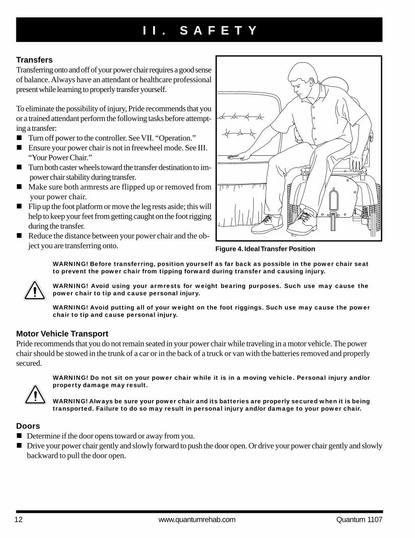
TransfersTransferring onto and off of your power chair requires a good senseof balance. Always have an attendant or healthcare professionalpresent while learning to properly transfer yourself.
To eliminate the possibility of injury, Pride recommends that youor a trained attendant perform the following tasks before attempt-ing a transfer:! Turn off power to the controller. See VII. “Operation.”! Ensure your power chair is not in freewheel mode. See III.
“Your Power Chair.”! Turn both caster wheels toward the transfer destination to im-
power chair stability during transfer.! Make sure both armrests are flipped up or removed from
your power chair.! Flip up the foot platform or move the leg rests aside; this will
help to keep your feet from getting caught on the foot riggingduring the transfer.
! Reduce the distance between your power chair and the ob-ject you are transferring onto.
WARNING! Before transferring, position yourself as far back as possible in the power chair seatto prevent the power chair from tipping forward during transfer and causing injury.
WARNING! Avoid using your armrests for weight bearing purposes. Such use may cause thepower chair to tip and cause personal injury.
Figure 4. Ideal Transfer Position
WARNING! Avoid putting all of your weight on the foot riggings. Such use may cause the powerchair to tip and cause personal injury.
Motor Vehicle TransportPride recommends that you do not remain seated in your power chair while traveling in a motor vehicle. The powerchair should be stowed in the trunk of a car or in the back of a truck or van with the batteries removed and properlysecured.
WARNING! Do not sit on your power chair while it is in a moving vehicle. Personal injury and/orproperty damage may result.
WARNING! Always be sure your power chair and its batteries are properly secured when it is beingtransported. Failure to do so may result in personal injury and/or damage to your power chair.
Doors! Determine if the door opens toward or away from you.! Drive your power chair gently and slowly forward to push the door open. Or drive your power chair gently and slowly
backward to pull the door open.

Quantum 1107 www.quantumrehab.com 13
I I . S A F E T Y
ElevatorsModern elevators have a door edge safety mechanism that, when pushed, reopens the elevator door(s).! If you are in the doorway of an elevator when the door(s) begin to close, push on the rubber door edge or allow the
rubber door edge to contact the power chair and the door will reopen.! Use care that pocketbooks, packages, or power chair accessories do not become caught in elevator doors.
Lift/Elevation ProductsIf you will be traveling with your power chair, you may find it necessary to use a lift/elevation product to aid in transporta-tion. Pride recommends that you closely review the instructions, specifications, and safety information set forth by themanufacturer of the lift/elevation product before using that product.
Positioning BeltsYour Quantum Rehab Specialist, therapist(s), and other healthcare professionals are responsible for determining yourrequirement for a positioning belt in order to operate your power chair safely.
WARNING! If you require a positioning belt to safely operate your power chair, make sure it isfastened securely. Serious personal injury may result if you fall from the power chair.
WARNING! The positioning belt is not designed for use as a seat belt in a motor vehicle. Nor isyour power chair suitable for use as a seat in any vehicle. Anyone traveling in a vehicle should beproperly belted into seats approved by the vehicle manufacturer.
Inclement Weather PrecautionsExposure of your power chair to inclement weather conditions should be avoided whenever possible. If suddenly caughtup in rain, snow, severe cold, or heat while operating your power chair proceed to shelter at the earliest opportunity.Thoroughly dry your power chair before storing, charging, or operating your power chair.
WARNING! Operating in rain, snow, salt, mist/spray conditions, and on icy/slippery surfaces cancause personal injury and/or damage to the power chair and electrical system. Maintain andstore your power chair in a dry and clean condition.
Reaching and BendingNever reach, lean, or bend while driving your power chair. If it is absolutely necessary to reach, lean, or bend while seatedon your power chair, it is important to maintain a stable center of gravity and keep the power chair from tipping. Priderecommends that the power chair user determine his/her personal limitations and practice bending and reaching in thepresence of a qualified healthcare professional.
WARNING! Do not bend, lean, or reach for objects if you have to pick them up from the floor byreaching down between your knees. Movements such as these may change your center of gravityand the weight distribution of the power chair. This may cause your power chair to tip, possiblyresulting in personal injury.
WARNING! Prevent personal injury! Keep your hands away from the tires when driving. Be awarethat loose fitting clothing can become caught in drive tires.

14 www.quantumrehab.com Quantum 1107
I I . S A F E T Y
Preventing Unintended Movement
WARNING! If you anticipate being seated in a stationary position for an extended period of time,turn off the power. This will prevent unexpected motion from inadvertent joystick contact. Thiswill also eliminate the possibility of unintended chair movement from electromagnetic (EM) sources.Failure to do so may result in personal injury.
Removable Parts
WARNING! Do not attempt to lift or move a power chair by any of its removable parts. Personalinjury and/or damage to the power chair may result.
BatteriesIn addition to following the warnings below, be sure to comply with all other battery handling information. For moreinformation about your power chair’s batteries, see VI. “Batteries and Charging.”
WARNING! Power chair batteries are heavy. See specifications table. If you are unable to lift thatmuch weight, be sure to get help. Lifting beyond your capacity can result in personal injury.
WARNING! Battery posts, terminals, and related accessories contain lead and lead compounds.Wash hands after handling.
WARNING! Always protect the batteries from freezing and never charge a frozen battery. Charginga frozen battery may result in personal injury and/or damage to the battery.
Prescription Drugs/Physical LimitationsUsers must exercise care and common sense when operating a power chair. This includes awareness of safety issues whentaking prescribed or over-the-counter drugs or when the user has specific physical limitations.
WARNING! Consult your physician if you are taking prescribed or over-the-counter medication orif you have certain physical limitations. Some medications and limitations may impair your abilityto operate your power chair in a safe manner.
AlcoholThe power chair user must exercise care and common sense when operating his/her power chair. This includes awarenessof safety issues while under the influence of alcohol.
WARNING! Do not operate your power chair while you are under the influence of alcohol, as thismay impair your ability to operate your power chair in a safe manner.

Quantum 1107 www.quantumrehab.com 15
Electromagnetic and Radio Frequency Interference (EMI/RFI)
WARNING! Laboratory tests have shown that electromagnetic and radio frequency waves canhave an adverse affect on the performance of electrically-powered mobility vehicles.
Electromagnetic and Radio Frequency Interference can come from sources such as cellular phones, mobile two-wayradios (such as walkie-talkies), radio stations, TV stations, amateur radio (HAM) transmitters, wireless computer links,microwave signals, paging transmitters, and medium-range mobile transceivers used by emergency vehicles. In somecases, these waves can cause unintended movement or damage to the control system. Every electrically-powered mobilityvehicle has an immunity (or resistance) to EMI. The higher the immunity level, the greater the protection against EMI. Thisproduct has been tested and has passed at an immunity level of 20 V/m.
WARNING! Be aware that cell phones, two-way radios, laptops, and other sources of radiotransmitters may cause unintended movement of your electrically powered mobility vehicle dueto EMI. Exercise caution when using any of these items while operating your mobility vehicle andavoid coming into close proximity of radio and TV stations.
WARNING! The addition of accessories or components to the electrically-powered mobility vehiclecan increase the susceptibility of the vehicle to EMI. Do not modify your power chair in any waynot authorized by Pride.
WARNING! The electrically-powered mobility vehicle itself can disturb the performance of otherelectrical devices located nearby, such as alarm systems.
NOTE: For further information on EMI/RFI, visit the Resource Center on www.pridemobility.com. If unintended motion orbrake release occurs, turn your power chair off as soon as it is safe to do so. Call Pride at 800-424-8205 to report the incident.
I I . S A F E T Y

16 www.quantumrehab.com Quantum 1107
I I I . Y O U R P O W E R C H A I R
THE QUANTUM 1107The Quantum 1107 has two main assemblies: the seat assembly and the power base assembly. See figure 5. Typically, theseat assembly includes the armrests, seatback, and seat base. The power base assembly includes two motor/brake assem-blies, two drive wheels, two anti-tip wheels, two caster wheels, two battery boxes, and wiring harnesses. See figure 5, 6,and 7.
Figure 5. The Quantum 1107
SEAT ASSEMBLY
POWER BASEASSEMBLY
ARMRESTS
FOOT PLATFORM
ANTI-TIP WHEELS
DRIVE WHEEL
CASTER WHEEL
SEATBACK
CONTROLLER
SEAT BASE

Quantum 1107 www.quantumrehab.com 17
I I I . Y O U R P O W E R C H A I R
QUANTUM 1107 SPECIFICATIONS
Suspension: Active-Trac
Drive Wheels: 10 in., pneumatic, (10 in., solid are optional)
Caster Wheels: 6 in., solid, rear-mounted
Anti-tip Wheels: 5 in., solid, front-mounted
Maximum Speed:¹ Up to 4.5 mph
Brakes: “Intelligent Braking” electronic regenerative, disc park brake
Ground Clearance:² 2.5 in.
Maximum Safe Slope: 5° (8.7%)
Turning Radius:² 20.5 in. (without foot riggings)
Overall Size:² Length: 36.625 in. (without foot riggings)
Width: 23 in.
Seating Options: Specialty Seat
Limited Recline High-Back Seat
Full Recline High-Back Seat
Synergy Seating Systems (Manual Tilt is optional)
Synergy TRU-Balance Power Positioning Systems
Drivetrain: Two motor, mid-wheel drive
Batteries: Two 12-volt, U-1 batteries (AGM or Gel-Cell type recommended)
Range:¹ Up to 25 miles
Battery Charger: 5-amp, off-board power cube
Electronics: 75-amp Pride FLIGHT Controller
70-amp PG Drives VSI Controller
70-amp PG Drives Remote Plus Controller
70-amp Microdrive Controller
Weight Capacity: 300 lbs.
160 lbs. with Synergy Manual Tilt
Component Weights: Base: 112 lbs. (right section 43 lbs.; left section 43 lbs.; center section 17 lbs.; battery boxes 4.5 lbs. each)
Specialty Seat: 37 lbs.
Batteries: 29 lbs. each
¹Varies with user weight, terrain type, battery amp hour rating (AH), battery charge, battery condition, and tire condition.²Due to manufacturing tolerances and continued product improvement, this specification can be subject to a varianceof (+ or – ) 3%.
NOTE: All specifications subject to change without notice.

18 www.quantumrehab.com Quantum 1107
Figure 6. The Quantum 1107 Power Base
SIDE FRAME HANDLES
BATTERY BOXES
FRONT TRAPEZE BAR
MANUALFREEWHEEL LEVER
MOTOR/BRAKE ASSEMBLY
CONTROLLER CABLECONNECTOR
I I I . Y O U R P O W E R C H A I R

Quantum 1107 www.quantumrehab.com 19
I I I . Y O U R P O W E R C H A I R
Electrical ComponentsThe electrical components consist of the controller assembly, the batteries, and the motors. The batteries, motors, andcontroller power module (if equipped) are located on the power base assembly. See figures 6 and 7. The controller islocated on the seat assembly. Connectivity between the controller and the motors, the batteries, and the battery chargeris provided by one or more wiring harnesses.
Controller Cable Connector: The controller cable connector is where the controller plugs into the power base. Eachcontroller uses a different type of harness. If the controller has a power module in the power base, the connector is a smallcommunications-type connector. If the controller is integrated, then the harness has a large 9-pin connector. Regardless ofwhich type of controller is used, the harness must be secured to the seat assembly and not allowed to drag on the floor.
Battery Harness Connector: This is where the controller connects to the battery boxes.
Figure 7. Quantum 1107 Electrical Components
BATTERY HARNESSCONNECTOR
CONTROLLER CABLE CONNECTOR
MOTORCONNECTOR
MOTOR CONNECTOR
CONTROLLER POWER MODULE

20 www.quantumrehab.com Quantum 1107
Main Circuit Breaker (located on rear battery box): The main circuit breaker is a safety feature built into your powerchair. When the batteries and the motors are heavily strained (e.g., from excessive loads), the main circuit breaker trips toprevent damage to the motors and the electronics. If the circuit trips, allow your power chair to “rest” for approximatelyone minute. Next, push in the circuit breaker button, turn on the controller, and continue normal operation. If the maincircuit breaker continues to trip repeatedly, contact your Quantum Rehab Specialist.
Controller Power Module: The controller power module enables the controller to communicate with the batteries andthe motors.
Motor Connectors: This is where the motors connect to the controller power module.
Manual Freewheel LeversYour power chair has a manual freewheel lever on each motor. See figure 6. Manual freewheel levers enable you todisengage the drive motors from the gearboxes and maneuver the chair manually.
WARNING! Do not use the power chair while the drive motors are disengaged! Do not disengagethe drive motors when the power chair is on an incline, as the unit could roll on its own, causinginjury!
To engage or disengage the drive motors:1. Locate the lever on top of each motor.2. Pull the two levers upward to engage the drive motors. See figure 8.3. Push the two levers downward to disengage the drive motors. See figure 9.
If a lever is difficult to move in either direction, slightly rock the power chair back and forth. The lever should then moveto the desired position.
WARNING! It is important to remember that when your power chair is in freewheel mode, thebraking system is disengaged.
I I I . Y O U R P O W E R C H A I R
Figure 8. Drive Mode (Drive Engaged) Figure 9. Freewheel Mode (Drive Disengaged)
MANUAL FREEWHEEL LEVERMANUAL FREEWHEEL LEVER

Quantum 1107 www.quantumrehab.com 21
Figure 10. Quantum 1107 Assembly View
INITIAL ASSEMBLYYour power chair may require some assembly either before initial use or after transportation. It may also require disassemblyto make some comfort adjustments. Figure 10 details those parts of the power chair that are designed to be disassembled andassembled by an end user or by a qualified caregiver before using the product or making comfort adjustments.
I V . A S S E M B L Y / D I S A S S E M B L Y
ARMREST ANGLE ADJUSTMENT
ANTI-TIP WHEELHEIGHT ADJUSTMENT
FOOT PLATFORM HEIGHT/DEPTH ADJUSTMENT
SEAT HEIGHT/ANGLEADJUSTMENT
CONTROLLER POSITION
SEAT INSTALLATION
NOTE: Any nylon insert lock nut removed during the disassembly or adjustment of the power chair must bereplaced with a new nut. Nylon insert lock nuts should not be reused as it may cause damage to the nyloninsert, resulting in a less secure fit. Replacement nylon insert lock nuts are available at local hardware storesor through your Quantum Rehab Specialist.

22 www.quantumrehab.com Quantum 1107
Figure 11. Rear Seat Interface Installation (Shown WithoutArmrests for Clarity)
Figure 12. Seat Installation (Shown Without Armrests forClarity)
Seat InstallationThe Quantum 1107 use a seat interface system to attachthe seat assembly to the power base assembly. This en-ables you to install and remove the seat quickly and easily.The main components are a pair of aluminum extrusionsmounted to the underside of the seat base and seat inter-face mounted on the power base. See figures 11 and 12.
WARNING! Avoid injury! Do not pick upthe seat assembly by the armrests. Theyare free to pivot, and you may losecontrol of the seat if they do so,resulting in personal injury or damageto the chair.
To install the seat (initial installation):1. Prior to initial installation, the rear seat interface needs
to be installed to the seat base.2. Slide the rear seat interface into the rear extrusion. See
figure 11.3. Squeeze the retaining pin and clip it onto the rear
seat interface.4. Slide the seat onto the side frame handles and slowly
lower the seat onto the front trapeze bar until it locksinto place. See figure 12.
5. Flip the seat latch safety down. See figure 12.
WARNING! Make sure the seat latchsafety is flipped down before using yourpower chair.
6. Install the controller into the mounting block under oneof the armrests.
7. Tighten the setscrews in the mounting block. See figure 20.8. Route the controller cable so that it cannot be pinched
in the seat hinge.9. Plug the controller into the connector on the power base.
See figure 7.10. Secure the controller cable to the armrest receiver with
one or more wire ties.
To remove the seat:1. Turn off the power to the controller.2. Disconnect the controller3. Flip up the seat latch safety.4. Squeeze the seat latch together. See figure 12.5. Pull the front of the seat up.6. Slide the seat forward and off of the power base.
I V . A S S E M B L Y / D I S A S S E M B L Y
REAR SEAT INTERFACEREAR EXTRUSION
RETAINING PIN
SEAT LATCH
SEAT LATCH SAFETY
FRONT EXTRUSION
SIDEFRAMEHANDLES
FRONT SEAT INTERFACE

Quantum 1107 www.quantumrehab.com 23
Power Base DisassemblyThe Quantum 1107 power base disassembles into six parts for easy transportation and storage. See figure 13.
To disassemble the power chair:1. Turn off the power to the controller.2. Disconnect the controller. See figure 6.3. Remove the seat.4. Press the foot platform release button and lift off the foot platform. See figure 13.5. Flip down the battery box latches on each side of the power base. See figure 14.6. Slide the battery boxes back and off of the power base.7. Flip up the center section latch. See figure 14.8. Rotate the center section forward.9. Grab a side section by the side frame handle.10. Lift the side section up and off of the center section.11. Grab the other side section by the side frame handle.12. Lift the second side section up and off of the center section.
NOTE: Perform the disassembly steps in reverse order to assemble the power chair.
NOTE: During assembly, make sure the battery box latches are in the up (locked) position and the centersection latch is in the down (locked) position.
I V . A S S E M B L Y / D I S A S S E M B L Y
Figure 13. Quantum 1107 Power Base Parts
FOOT PLATFORMRELEASE BUTTON
RIGHT FRAME SECTION
LEFT FRAME SECTION
REAR BATTERY BOX
FRONT BATTERY BOX
FOOT PLATFORM
CENTER SECTION

24 www.quantumrehab.com Quantum 1107
Figure 14. Quantum 1107 Battery Box Removal and Frame Separation
BATTERY BOX LATCH(LOCKED)
BATTERY BOX LATCH(UNLOCKED)
I V . A S S E M B L Y / D I S A S S E M B L Y
CENTER SECTION LATCH

Quantum 1107 www.quantumrehab.com 25
V . C O M F O R T A D J U S T M E N T S
COMFORT ADJUSTMENTSAfter becoming familiar with your power chair’s operation, you may find the need to make some adjustments to increase yourcomfort. These adjustments include seat height and angle, armrest angle, foot platform height and angle, and controllerposition. If your power chair is equipped with a Specialty Seat or a Synergy Seat, refer to the information provided in separatemanuals. If your power chair is equipped with a contoured seat, refer to the following information.
WARNING! If your power chair was configured by your Quantum Rehab Specialist, please consultyour healthcare professional before changing the seat position or making any other adjustment.Some adjustments may degrade your power chair’s performance and safety by changing its center ofgravity.
WARNING! Some power chair components are heavy. You may need assistance to lift or carrythem. Please refer to the specifications table for specific component weights before youdisassemble the power chair.
WARNING! Prevent injury. Remove the occupant from the power chair before making anyadjustments/repairs.
Figure 16. Side Seat Interface Height Adjustment
Figure 15. Front Trapeze Bar Height Adjustment
You may need the following to make comfort adjustments:! metric/standard socket set and ratchet! adjustable wrench! thread lock
Seat Height and Seat Angle AdjustmentYou can change the seat height to one of two positions in 1-in.increments by raising the front trapeze bar and side frame handles.See figures 15 and 16. If you raise or lower either the front tra-peze bar or the side frame handles, you can also change the seatbase angle (dump).
To change the seat height:1. Turn off the power to the controller.2. Disconnect the controller from the power base. See figure 6.3. Remove the seat from the power base.4. Loosen the screws that attach the front trapeze bar and side
frame handles to the seat posts. See figures 15 and 16.5. Remove the retaining clips that secure the seat posts to the
power base.6. Move the trapeze bar and frame handles up or down to the
desired height.
NOTE: Change the seat dump by raising or loweringonly one set of posts (front or back.)
7. Reinstall the retaining clips.8. Remove each screw from the front trapeze bar and side
frame handles and apply thread lock.9. Reinstall each screw into the front trapeze bar and side
frame handles and tighten.
RETAININGCLIPS
SEAT POST
SEAT POST
RETAININGCLIPS
SIDE FRAME HANDLES
FRONT TRAPEZE BAR

26 www.quantumrehab.com Quantum 1107
Figure 17. Seat Position (Extrusion Location onContour Seat)
V . C O M F O R T A D J U S T M E N T S
10. Reinstall the seat.11. Reconnect the controller to the power base.
Seat PositionYou can move the seat forward or rearward by changing theextrusion mounting position.
To change the position:1. Turn off the power to the controller.2. Unplug the controller from the power base.3. Remove the seat from the power base.4. Remove both extrusions from the bottom of the seat. See
figure 17.5. Reposition the extrusions on a different set of mounting holes.
You must move both extrusions the same number of holes eitherforward or backward. See figure 17.
6. Fasten the extrusions back onto the bottom of the seat.7. Reinstall the seat.8. Plug the controller into the power base.
Seatback Angle AdjustmentIf your power chair is equipped with an adjustable seatback,you can adjust it to four (4) different angles: 90°, 102°, 105°,or 107°.
To adjust the seatback angle:1. Remove the seatback angle adjusting screw from each
seat hinge. See figure 18.2. Set the seatback at the desired angle.3. Reinstall the seatback angle adjusting screw to each
seat hinge and tighten.
Manual Recline Seatback AdjustmentIf your power chair is equipped with a reclining seat, you canadjust the seatback angle with the seatback release lever. Thelever is located on the right side of the seat base.
To adjust the recline angle:1. Pull up on the seatback release lever.2. Lean forward or backward to the desired position.3. Release the lever.
Armrest Width AdjustmentYou can change each armrest’s width independently of the other.
Figure 18.Seatback Angle Adjustment
JAM NUTS
ARMRESTANGLEADJUSTINGSCREW
SEAT HINGE
SEATBACKANGLEADJUSTINGSCREW
ARMREST KNOB
NOTE: Changing the armrest width may increase theoverall width of your power chair.
Quantum 1107 www.quantumrehab.com 27
V . C O M F O R T A D J U S T M E N T S
To change the armrest width:1. Locate the armrest knob on each side of the armrest receiver
bracket. See figure 18.2. Loosen each knob.3. Slide the armrests in or out to the desired width.4. Tighten each knob.
Armrest Angle AdjustmentTo change the armrest angle:1. Lift the armrest straight up so that it is perpendicular to the floor.
See figure 18.2. Loosen the jam nuts.3. Turn the armrest angle adjusting screw clockwise to lower the
front of the armrest, or counterclockwise to raise the front ofthe armrest.
4. Tighten the jam nuts to lock the armrest angle adjusting screwinto place.
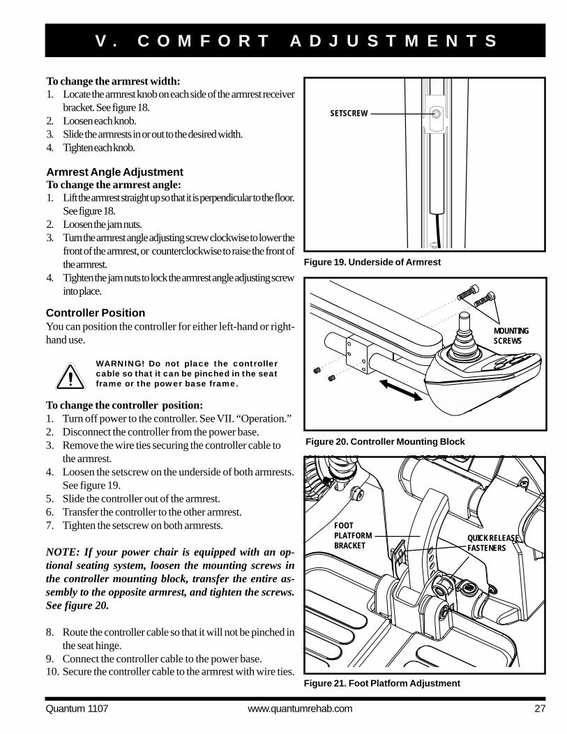
Figure 21. Foot Platform Adjustment
FOOTPLATFORMBRACKET
QUICK RELEASEFASTENERS
Figure 20. Controller Mounting Block
Controller PositionYou can position the controller for either left-hand or right-hand use.
WARNING! Do not place the controllercable so that it can be pinched in the seatframe or the power base frame.
To change the controller position:1. Turn off power to the controller. See VII. “Operation.”2. Disconnect the controller from the power base.3. Remove the wire ties securing the controller cable to
the armrest.4. Loosen the setscrew on the underside of both armrests.
See figure 19.5. Slide the controller out of the armrest.6. Transfer the controller to the other armrest.7. Tighten the setscrew on both armrests.
NOTE: If your power chair is equipped with an op-tional seating system, loosen the mounting screws inthe controller mounting block, transfer the entire as-sembly to the opposite armrest, and tighten the screws.See figure 20.
8. Route the controller cable so that it will not be pinched inthe seat hinge.
9. Connect the controller cable to the power base.10. Secure the controller cable to the armrest with wire ties.
Figure 19. Underside of Armrest
SETSCREW
MOUNTINGSCREWS

28 www.quantumrehab.com Quantum 1107
V . C O M F O R T A D J U S T M E N T S
3. Reinstall the quick release fasteners into the foot platformbracket and tighten.
Foot Platform Depth AdjustmentTo adjust the foot platform depth:1. Remove the quick release fasteners from the foot platform
bracket. See figure 21.2. Move the foot platform in or out to the desired depth.3. Reinstall the quick release fasteners into the foot platform
bracket and tighten.
Quick Release FastenersThe foot platform is attached to the power base with twoquick release fasteners. See figure 21. Each quick releasefastener consists of a bolt, a lever, and a nut. See figure 22.The lever has a cam on the end that allows it to clamp intoplace. The quick release fastener has two states: clampedand unclamped. When the lever is open, the quick releasefastener is unclamped. When the lever is closed, the quickrelease fastener is clamped.
To clamp the quick release fastener:1. Make sure the lever is in the open position.2. Turn the nut clockwise until it is snug.3. Rotate the lever until it is in the fully closed position.
NOTE: If the lever will not rotate to the fully closedposition, then turn the nut counterclockwise one-quar-ter or one-half turn.
Foot Platform Angle AdjustmentYou can adjust the angle of the foot platform with a hex key.See figure 23.
To adjust the foot platform angle:1. Flip up the foot platform and locate the setscrew.2. Turn the setscrew counterclockwise to raise the front
of the foot platform.3. Turn the setscrew clockwise to lower the front of the
foot platform. Figure 24. Swing-Away Footrests
FOOTRESTADJUSTMENTSCREWS
FOOTRESTEXTENSION
SFR RELEASE LEVER
Figure 23. Underside of Foot Platform
SETSCREW
BOLTNUT
CAM
Figure 22. Quick Release Fasteners
LEVER (OPEN)UNCLAMPED
LEVER (FULLY CLOSED)CLAMPED
Foot Platform Height AdjustmentThe foot platform height is easily adjusted to different heightsin 1/2-in. increments.
To raise or lower the foot platform:1. Remove the quick release fasteners from the foot platform
bracket. See figure 21.2. Raise or lower the foot platform to the desired height.

Quantum 1107 www.quantumrehab.com 29
V . C O M F O R T A D J U S T M E N T S
Swing-away FootrestsSwing-away Footrests (SFRs) enable you to rotate thefootrests to the side before you transfer onto or off ofyour power chair.
To rotate the SFRs:1. Push in the release lever. See figure 24.2. Rotate the SFRs.
To adjust the SFR length:1. Remove the two adjustment screws from the side of each
footrest extension. See figure 24.2. Slide the footrest up or down to the desired length.3. Reinstall the two adjustment screws.
Elevating Leg Rests (Optional)Elevating Leg Rests (ELRs) offer an infinite range of ad-justment for the leg angle and a footrest adjustment rangeof 12–19 in.
To rotate the ELRs:1. Push in release lever A. See figure 25.2. Rotate the ELRs.
To adjust the ELR length:1. Remove the two adjustment screws from the side of each leg
rest extension. See figure 25.2. Slide the leg rest up or down to the desired length.3. Reinstall the two adjustment screws.
To adjust the ELR angle:1. Push down release lever B. See figure 25.2. Move the leg rest to the desired angle.
LEG RESTADJUSTMENTSCREWS
Figure 25. Elevating Leg Rests
LEG RESTEXTENSION
RELEASE LEVER B
RELEASE LEVER A
A
C
D
B
B
C
D
A
Figure 26. Multi-Axis Foot Plate (ELR Shown)
SETSCREW
Multi-Axis Foot PlateThe multi-axis foot plate assembly can be installed on either aswing-away footrest or an elevating leg rest. The multi-axis footplate has four adjustments: leg rest length (A), position (B), tilt(C), and angle (D). See figure 26.
To change leg rest length (A):1. Remove the hardware.2. Move the leg rest to the desired position.3. Reinstall the hardware.

30 www.quantumrehab.com Quantum 1107
V . C O M F O R T A D J U S T M E N T S
To change foot plate tilt (C):1. Loosen the hardware.2. Tilt the foot plate to desired position.3. Tighten the hardware.
To change foot plate angle (D):1. Turn the setscrew clockwise to decrease the angle.2. Turn the setscrew counterclockwise to increase the angle.
NOTE: Each drive tire must be inflated to 35 psi (2.4 bar) if equipped with pneumatic tires. The user must alsobe seated in the power chair in order to properly adjust the anti-tip wheels.
To adjust the anti-tip wheels:1. Loosen nut A. See figure 27.2. Remove bolt B.3. Raise or lower the anti-tip wheel. Each hole is 1/2-in. apart.4. Reinstall bolt B.5. Tighten nut A.6. Raise or lower the other anti-tip wheel so that it is at the same height.
NUT A
BOLT B
Anti-Tip Wheels AdjustmentThe anti-tip wheels are designed to give your power chairincreased stability on rough surfaces. The anti-tip wheels arepreset at the factory for smooth surfaces or indoor use only.If you plan on using your power chair on rough surfaces, itmay be necessary to adjust the anti-tip wheels to better suityour needs. The anti-tip wheels may need adjustment if thefollowing occurs:! When coming to a stop, your power chair tips forward excessively.! The anti-tip wheels constantly rub the ground.
WARNING! Consult your Quantum Rehab Specialist before attempting to change the anti-tip wheelheight! Changing the anti-tip wheel height affects handling under acceleration!
WARNING! The higher you raise the anti-tip wheels, the more you increase your power chair’stendency to tilt forward while decelerating. You can compensate for this by having your QuantumRehab Specialist make a small adjustment to the pre-programmed deceleration setting in thecontroller or by moving the seat assembly farther to the back of your power chair.
PROHIBITED! Do not remove the anti-tip wheels.
To change foot plate position (B):1. Remove the hardware.2. Move the foot plate to the desired position.3. Reinstall the hardware.
Figure 27. Anti-Tip Wheel Assembly

Quantum 1107 www.quantumrehab.com 31
V I . B A T T E R I E S A N D C H A R G I N G
BATTERIES AND CHARGINGYour power chair uses two long-lasting, 12-volt, deep-cycle batteries. These batteries are sealed and maintenance free. Sincethey are sealed, there is no need to check the electrolyte (fluid) level. Deep-cycle batteries are designed to handle a longer anddeeper discharge. Though they are similar in appearance to automotive batteries, they are not interchangeable. Automotivebatteries are not designed to handle a long, deep discharge, and also are unsafe for use in power chairs.
WARNING! Battery posts, terminals, and related accessories contain lead and lead compounds.Wash hands after handling.
WARNING! Prevent injury and/or equipment damage! Do not use batteries that exceed therecommended type and amp-hour capacity. Do not use batteries with different amp-hour capacities.Refer to specifications table in this manual and in the manual suppled with the battery chargerfor recommended type and capacities.
Charging the BatteriesThe battery charger is essential in providing long life for your power chair batteries. It is designed to optimize your powerchair’s performance by charging the batteries safely, quickly, and easily.
PROHIBITED! Removal of grounding prong can create electrical hazard. If necessary, properlyinstall an approved 3-pronged adapter to an electrical outlet having 2-pronged plug access. Failureto heed could result in personal injury and/or property damage.
PROHIBITED! Never use an extension cord to plug in your battery charger. Plug the charger directlyinto a properly wired standard electrical outlet.
WARNING! You must recharge your power chair’s batteries with the supplied charger. Do not usean automotive-type battery charger.
WARNING! Prevent injury and/or equipment damage! Read the battery charging instructions inthis manual and in the manual supplied with the battery charger before charging the batteries.
WARNING! Prevent injury and/or equipment damage! Do not expose the off-board battery chargerto rain or other sources of moisture unless it has been tested for outdoor use. Refer to the manualsupplied with the battery charger for more information.
WARNING! Prevent injury and/or equipment damage! Explosive gases may be generated whilecharging the batteries. Keep the power chair and battery charger away from sources of ignitionsuch as flames or sparks and provide adequate ventilation when charging the batteries.
WARNING! Prevent injury and/or equipment damage! Inspect the battery charger, wiring, andconnectors for damage before each use. Contact your Quantum Rehab Specialist if damage isfound.
WARNING! Prevent injury and/or equipment damage! Do not attempt to open the battery chargercase. If the battery charger does not appear to be working correctly, contact your QuantumRehab Specialist.
WARNING! Prevent injury and/or equipment damage! If the off-board battery charger is equippedwith cooling slots, then do not attempt to insert objects through these slots.
WARNING! Prevent injury and/or equipment damage! Do not allow unsupervised children to playnear the power chair while the batteries are charging.
WARNING! Prevent injury and/or equipment damage! If your off-board battery charger has notbeen tested and approved for outdoor use, then do not expose it to adverse or extreme weatherconditions. If the battery charger is exposed to adverse or extreme weather conditions, then itmust be allowed to adjust to the difference in environmental conditions before use indoors. Referto the manual supplied with the battery charger for more information.

32 www.quantumrehab.com Quantum 1107
V I . B A T T E R I E S A N D C H A R G I N G
To charge the batteries using the off-board charger:1. Position your power chair next to a standard elec-
trical outlet.2. Be certain the controller power is turned off.3. Plug the off-board charger into the off-board
charger/programming socket on the controller. SeeVII. “Operation.”
4. Plug the off-board charger into the electrical outlet.
NOTE: If it is a Pride off-board charger, then thereare two lights in it. The red light indicates thatpower to the off-board charger is on. The greenlight indicates that the batteries are fully charged.If it is not a Pride off-board charger, then followthe instructions supplied by the manufacturer.
5. When the batteries are fully charged, unplug the off-board charger from the electrical outlet and thenfrom the controller.
NOTE: You can remove both battery boxes from the power base and charge them using the off-board charger portlocated on the front battery box. The battery boxes must be connected in order to charge them. See figure 28.
WARNING! When charging through the battery boxes, never use greater than a 5-amp chargingsystem. Failure to comply may result in damage to your power chair.
Battery Break-inTo break in new batteries for maximum efficiency:1. Fully recharge any new battery prior to its initial use. This brings the battery up to about 90% of its peak performance level.2. Operate your power chair throughout the house and yard. Move slowly at first, and don’t travel too far until you become
accustomed to the controls and break in the batteries.3. Give the batteries another full charge of 8 to 14 hours and operate your power chair again. The batteries will now perform at over
90% of their potential.4. After four or five charging cycles, the batteries will top off at 100% charge and last for an extended period.
Frequently Asked Questions (FAQs)
How does the charger work?The battery charger takes the standard electrical outlet voltage of 120 VAC (alternating current) and converts it to 24VDC (direct current). The power chair batteries use direct current to run your power chair. When the battery voltage islow, the charger works harder to charge the battery. As the battery voltage approaches full charge, the charger doesn’twork as hard to complete the charging cycle. When the battery is fully charged, the amperage from the charger is nearly atzero. This is how the charger maintains a charge but does not overcharge the battery.
Figure 28. Battery Boxes (Removed from Power Base)
OFF-BOARD CHARGER PORT

Quantum 1107 www.quantumrehab.com 33
V I . B A T T E R I E S A N D C H A R G I N G
Can I use a different battery charger?You should use the charger supplied with the power chair. It is the safest, most efficient tool to charge the batteries. We donot recommend using other types of chargers (e.g., an automotive battery charger).
NOTE: Your power chair’s charger will not operate after the batteries have been discharged to nearly zerovoltage. If this happens, call your Quantum Rehab Specialist for assistance.
How often must I charge the batteries?Many factors come into play when deciding how often to charge the batteries. You may use your power chair all day on adaily basis or you may not use it for weeks at a time.
! Daily UseIf you use your power chair on a daily basis, charge the batteries as soon as you are finished using your power chair.Your power chair will be ready each morning to give you a full day’s service. It is recommended that you charge thebatteries 8 to 14 hours after daily use.
! Infrequent UseIf you use your power chair infrequently (once a week or less), you should charge the batteries at least once per weekfor 12 to 14 hours.
NOTE: Keep your batteries fully charged and avoid deeply discharging your batteries. Do not charge thebatteries for more than 24 hours at a charging cycle.
How can I get maximum range or distance per charge?Rarely do you have an ideal driving situation such as smooth, flat, hard terrain with no wind, hills, or curves. More often youare presented with hills, sidewalk cracks, uneven and loosely packed surfaces, curves, and wind. All of these factors willaffect the distance or running time per battery charge. Below are a few suggestions for obtaining the maximum range percharge:! Always charge the batteries fully prior to your trip.! Plan your trip in advance to avoid inclines if possible.! Limit baggage weight to essential items.! Try to maintain an even speed and avoid stop-and-go driving.
What type of batteries should I use?We recommend deep-cycle batteries that are sealed and maintenance free. Both AGM and Gel-Cell are deep-cyclebatteries that are similar in performance. Refer to the specifications table for more battery information.
WARNING! Corrosive chemicals contained in batteries. Use only AGM or Gel-Cell batteries toreduce the risk of leakage or explosive conditions.
Why do my new batteries seem weak?Deep-cycle batteries employ a much different chemical technology than that used in car batteries, nickel-cadmium (nicads),or in other common battery types. Deep-cycle batteries are specifically designed to provide power, drain down theircharge, and then accept a relatively quick recharge. AGM and Gel-Cell batteries should be charged as often as possible.They do not have a “memory” like nickel-cadmium batteries.

34 www.quantumrehab.com Quantum 1107
We work closely with our battery manufacturer to provide a battery that best suits your power chair’s specific demands.Fresh batteries arrive regularly at Pride and are promptly shipped with a full charge. During shipping, the batteries encoun-ter temperature extremes that may influence initial performance. Heat robs the charge from the battery, and cold slows thepower available and extends the time needed to recharge the battery (just as with a car battery).
It might take a few days for the temperature of the battery to stabilize and adjust to its new ambient temperature. Moreimportantly, it will take a few “charging cycles” (a partial drain— then a full recharge) to establish the critical chemicalbalance that is essential to the battery’s peak performance and long life. It will be well worth it to take the time to break inyour battery properly.
NOTE: The useful life of a battery is quite often a reflection of the care it receives.
How can I ensure maximum battery life?A fully charged deep-cycle battery will provide reliable performance and extended battery life. Keep your power chair’sbatteries fully charged whenever possible. Batteries that are regularly and deeply discharged, infrequently charged, orstored without a full charge may be permanently damaged, causing unreliable power chair operation and limited battery life.
How should I store my power chair and its batteries?If you do not use your power chair regularly, we recommend maintaining battery vitality by charging the batteries at leastonce per week.
If you do not plan on using your power chair for an extended period, fully charge the batteries prior to storage. Disconnectthe battery harnesses and store the power chair in a warm, dry environment. Avoid temperature extremes, such as freezingand excessively hot conditions, and never attempt to charge a frozen battery. A cold or frozen battery should be warmedfor several days prior to recharging.
What about public transportation?AGM and Gel-Cell batteries are designed for application in power chairs and other mobility vehicles. These batteries areFederal Aviation Administration (FAA) approved, allowing safe transportation on aircraft, buses, and trains, as there is nodanger of spillage or leakage. We suggest you contact the carrier’s ticket counter in advance to determine that carrier’sspecific requirements.
What about shipping?If you wish to use a freight company to ship your power chair to your final destination, repack your power chair in theoriginal shipping container and ship the batteries in separate boxes.
V I . B A T T E R I E S A N D C H A R G I N G

Quantum 1107 www.quantumrehab.com 35
V I I . O P E R A T I O N
Figure 29. FLIGHT Controller
2
3
4
5
1
FLIGHT CONTROLLERThe electronic controller is what you use to operate your power chair. It takes the battery voltage and sends it to theappropriate system. The electronic controller enables you to move the power chair, as well as monitor battery charge,electronic controller functions, and the condition of your electrical system. The FLIGHT is part of a modular electroniccontroller system. The system consists of more than one module. Typically, the FLIGHT is mounted to one of the armrests.See figure 29. It is connected to a power module located on the power base through the controller communications cable.The FLIGHT may be used to control some optional systems, such as lights.
The controller supplied with your power chair has been pre-programmed to meet your needs. The program is set usingeither a personal computer with software provided by the controller manufacturer or with a hand-held programmer, alsoprovided by the controller manufacturer.
WARNING! The controller program can affect speed, acceleration, deceleration, and braking. If itis programmed incorrectly or outside of the safe limits as determined by your healthcareprofessional, it can create a dangerous situation. Only the power chair manufacturer, an authorizedrepresentative of the manufacturer, or a trained service technician should program the controller.
The FLIGHT consists of:1. joystick2. keypad3. off-board charger/programming socket4. controller connector5. controller power module
JoystickThe joystick controls the direction and speed of your powerchair. When you move the joystick from the neutral (cen-ter) position, the electromagnetic brakes release and allowyour power chair to move. The farther you push the joy-stick from its neutral position, the faster your power chairmoves. When you release the joystick and allow it to returnto the neutral position, you engage the electromagneticbrakes. This causes your power chair to decelerate andcome to a complete stop.
WARNING! If your power chair begins tomove in an unexpected manner,immediately release the joystick. Unless thejoystick is damaged, this action should stopyour power chair.
KeypadThe keypad is located in front of the joystick. It containskeys necessary to operate your power chair. See figure 30.

36 www.quantumrehab.com Quantum 1107
Figure 30. FLIGHT Controller Keypad
V I I . O P E R A T I O N
BATTERYCONDITION
METER
TORTOISEKEY
ON/OFFKEY
SPEEDSETTING
INDICATOR
HAREKEY
HAZARDLIGHT KEY
(OPTIONAL)
HORNKEY
HEADLIGHTKEY (OPTIONAL)
LEFT TURNSIGNAL KEY(OPTIONAL)
RIGHT TURNSIGNAL KEY(OPTIONAL)
ACTUATOR LIGHTS
INDICATOR LIGHTINDICATOR LIGHT
SEAT ACTUATORKEY (OPTIONAL)
On/Off KeyThe on/off key turns the FLIGHT on and off.
WARNING! Unless faced with an emergency situation,do not use the on/off key to stop the chair. This willcause the power chair to stop abruptly.
WARNING! Always turn the power off when you arestationary to prevent unexpected movement.
Battery Condition MeterThe battery condition meter consists of ten lights arranged in an arcover the on/off key. As the battery voltage drops, the number oflights reduces from right to left. When the battery capacity drops to10% or below, the left red LED will flash.! Left Red LED Flashing: Battery charge is low; charge the
batteries as soon as possible.! Right-to-Left Ripple of LEDs: FLIGHT is in lock mode; un-
lock the FLIGHT.! Left-to-Right Ripple of LEDs Alternating with Steady Dis-
play: FLIGHT is in programming, inhibit, or charging mode.! Right Green LED Flashing: FLIGHT is in speed limit mode.! All LEDs Flashing Slowly: The joystick was not in the neutral
position when the controller was turned on. If you get “all LEDsflashing slowly,” turn off the controller, allow the joystick to return tothe neutral position, then turn on the controller.
! All LEDs Flashing Quickly: The FLIGHT has detected a fault; Refer to the Error Code table.
Lock ModeThe FLIGHT controller is equipped with a feature that enables you to “lockout” unauthorized users.
To lock the FLIGHT controller:1. While the power is on, press and hold the on/off key for 2 seconds. The display will turn off immediately. After 2
seconds, all LEDs will flash briefly and the horn will sound a short beep.2. The FLIGHT controller is now locked.
To unlock the FLIGHT controller:1. While the FLIGHT is locked, press the on/off key to turn on the FLIGHT. All LEDs will flash briefly. The LEDs will
then slowly ripple from right to left.2. Press the horn key twice before the LED ripple has completed, approximately 10 seconds. The FLIGHT is now
unlocked.
Actuator Keys and Actuator Lights (For Optional Equipment)Actuator keys and actuator lights are used for optional equipment such as power elevating leg rests. For specific operationof the actuator keys and actuator lights, contact your Quantum Rehab Specialist.

Quantum 1107 www.quantumrehab.com 37
V I I . O P E R A T I O N
Horn KeyThe horn key activates the horn.
Speed KeysThere are two keys that control the speed. Press the hare key to increase the speed. Press the tortoise key to decrease thespeed. The speed setting is displayed on the speed setting indicator. If your power chair was programmed with a driveprofile, contact your Quantum Rehab Specialist for more information.
NOTE: We recommend that the first few times you operate your power chair, you set the speed to the slowestsetting until you become familiar with your new power chair.
Off-board Charger/Programming SocketYou may use an off-board charger to charge the power chair batteries through the 3-pin socket located on the front of theFLIGHT. If you use an off-board charger, the charger current should not exceed 8 amps. Contact your Quantum RehabSpecialist for more information.
WARNING! Only chargers with Neutrik NC3MX plugs should be connected to the off-board charger/programming socket. See your Quantum Rehab Specialist for more information.
NOTE: The socket may also be used for reprogramming the FLIGHT. Contact your Quantum Rehab Special-ist for more information.
Sleep Mode (If Enabled)The power chair controller features a sleep mode. Sleep mode is a built-in circuit that will automatically shut off the mainpower if the joystick is not moved in any direction for a period of time. This time factor is programmed into the controller.To restore power and continue, push any key on the keypad.
Error CodesThe battery condition meter will flash error codes when the FLIGHT controller detects an abnormal condition in theelectrical system. All of the battery condition meter LEDs will flash a number of times quickly, then pause, then flash again.The battery condition meter will continue to flash the error codes until the problem is fixed. The table below identifies theindividual error codes. If any of these error codes persist, contact your Quantum Rehab Specialist.
Error Code Probable Cause Possible Solution1 Possible stall timeout or user error Release the joystick
2 Battery Fault Check the batteries and cables. Try to charge the
batteries. The batteries may need to be replaced.
3 Left Motor Fault Check the left motor, connections, and cabling.
4 Right Motor Fault Check the right motor, connections, and cabling.
5 Left Park Brake Fault Check the left park brake, connections, and cabling.
6 Right Park Brake Fault Check the right park brake, connections, and cabling.
7 FLIGHT Controller Module Fault Check the communications connections and wiring.
8 FLIGHT Power Module Fault Check the communications connections and wiring.
9 FLIGHT Communications Fault Check the communications connections and wiring.
10 Unknown Fault Contact your Quantum Rehab Specialist.
11 Incompatible Controller Fault Contact your Quantum Rehab Specialist.
38 www.quantumrehab.com Quantum 1107
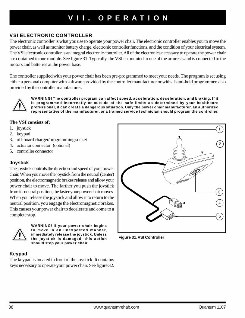
VSI ELECTRONIC CONTROLLERThe electronic controller is what you use to operate your power chair. The electronic controller enables you to move thepower chair, as well as monitor battery charge, electronic controller functions, and the condition of your electrical system.The VSI electronic controller is an integral electronic controller. All of the electronics necessary to operate the power chairare contained in one module. See figure 31. Typically, the VSI is mounted to one of the armrests and is connected to themotors and batteries at the power base.
The controller supplied with your power chair has been pre-programmed to meet your needs. The program is set usingeither a personal computer with software provided by the controller manufacturer or with a hand-held programmer, alsoprovided by the controller manufacturer.
WARNING! The controller program can affect speed, acceleration, deceleration, and braking. If itis programmed incorrectly or outside of the safe limits as determined by your healthcareprofessional, it can create a dangerous situation. Only the power chair manufacturer, an authorizedrepresentative of the manufacturer, or a trained service technician should program the controller.
The VSI consists of:1. joystick2. keypad3. off-board charger/programming socket4. actuator connector (optional)5. controller connector
JoystickThe joystick controls the direction and speed of your powerchair. When you move the joystick from the neutral (center)position, the electromagnetic brakes release and allow yourpower chair to move. The farther you push the joystickfrom its neutral position, the faster your power chair moves.When you release the joystick and allow it to return to theneutral position, you engage the electromagnetic brakes.This causes your power chair to decelerate and come to acomplete stop.
Figure 31. VSI Controller
V I I . O P E R A T I O N
WARNING! If your power chair beginsto move in an unexpected manner,immediately release the joystick. Unlessthe joystick is damaged, this actionshould stop your power chair.
KeypadThe keypad is located in front of the joystick. It containskeys necessary to operate your power chair. See figure 32.
Quantum 1107 www.quantumrehab.com 39
V I I . O P E R A T I O N
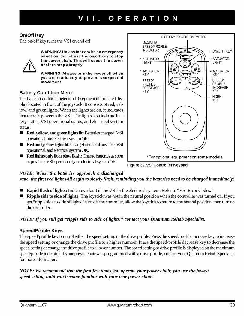
On/Off KeyThe on/off key turns the VSI on and off.
WARNING! Unless faced with an emergencysituation, do not use the on/off key to stopthe power chair. This will cause the powerchair to stop abruptly.
WARNING! Always turn the power off whenyou are stationary to prevent unexpectedmovement.
Battery Condition MeterThe battery condition meter is a 10-segment illuminated dis-play located in front of the joystick. It consists of red, yel-low, and green lights. When the lights are on, it indicatesthat there is power to the VSI. The lights also indicate bat-tery status, VSI operational status, and electrical systemstatus.! Red, yellow, and green lights lit: Batteries charged; VSI
operational, and electrical system OK.! Red and yellow lights lit: Charge batteries if possible; VSI
operational, and electrical system OK.! Red lights only lit or slow flash: Charge batteries as soon
as possible; VSI operational, and electrical system OK.
NOTE: When the batteries approach a dischargedstate, the first red light will begin to slowly flash, reminding you the batteries need to be charged immediately!
! Rapid flash of lights: Indicates a fault in the VSI or the electrical system. Refer to “VSI Error Codes.”! Ripple side to side of lights: The joystick was not in the neutral position when the controller was turned on. If you
get “ripple side to side of lights,” turn off the controller, allow the joystick to return to the neutral position, then turn onthe controller.
NOTE: If you still get “ripple side to side of lights,” contact your Quantum Rehab Specialist.
Speed/Profile KeysThe speed/profile keys control either the speed setting or the drive profile. Press the speed/profile increase key to increasethe speed setting or change the drive profile to a higher number. Press the speed/profile decrease key to decrease thespeed setting or change the drive profile to a lower number. The speed setting or drive profile is displayed on the maximumspeed/profile indicator. If your power chair was programmed with a drive profile, contact your Quantum Rehab Specialistfor more information.
NOTE: We recommend that the first few times you operate your power chair, you use the lowestspeed setting until you become familiar with your new power chair.
Figure 32. VSI Controller Keypad

40 www.quantumrehab.com Quantum 1107
Actuator Keys and Actuator Lights (For Optional Equipment)Actuator keys and actuator lights are used for optional equipment such as power elevating leg rests. For specific operationof the actuator keys and actuator lights, contact your Quantum Rehab Specialist.
Horn KeyThe horn key activates the horn.
Locking/Unlocking the VSIThe VSI has a feature that enables you to lock your power chair to prevent unauthorized use.
To lock the VSI:1. With the VSI switched on, press and hold the on/off key. After 1 second, the VSI should beep.2. Release the on/off key.3. Push the joystick to the full forward position until the VSI beeps.4. Pull the joystick to the full rearward position until the VSI beeps.5. Release the joystick. There should be a long beep.6. The VSI is now locked.
To unlock the VSI:1. Press the on/off key and power on the VSI. The maximum speed/profile indicator should ripple side to side.2. Push the joystick to the full forward position until the VSI beeps.3. Pull the joystick to the full rearward position until the VSI beeps.4. Release the joystick. There should be a long beep.5. The VSI is now unlocked.
NOTE: If the above procedure fails to either lock or unlock the VSI, contact your Quantum Rehab Specialist.
Off-board Charger/Programming SocketThe off-board charger/programming socket is located on the front of the VSI. If you use an off-board charger, the chargercurrent should not exceed 8 amps. Contact your Quantum Rehab Specialist for more information.
WARNING! Only chargers with Neutrik NC3MX plugs should be connected to the off-board charger/programming socket. See your Quantum Rehab Specialist for more information.
Actuator Connector (Optional)The actuator connector connects the VSI to optional powered systems such as elevating leg rests.
Controller ConnectorThe controller connector connects the VSI to the power chair’s batteries, motors, and motor brakes.
WARNING! Failure to properly align the connectors can result in damage to the VSI, the charger,and the connectors.
V I I . O P E R A T I O N

Quantum 1107 www.quantumrehab.com 41
Thermal RollbackThe VSI controller is equipped with a thermal rollback circuit. This circuit monitors the temperature of the controller, whichroughly translates to motor temperature. In the event that the VSI controller becomes excessively hot (above 140° F), motorcurrent (amperage) is reduced. For every degree above 140° F, the motor current limit is reduced by .55 amps until the VSIcontroller reaches 158° F, at which time the current output is reduced to zero. This reduces your power chair’s “power,”which could also reduce your power chair’s speed, and allows the electrical components and motors to cool down. When thetemperature returns to a safe level, your power chair resumes its normal operation.
VSI Error CodesThe VSI controller is designed with the user’s safety as the prime consideration. It incorporates many sophisticated self-test features which search for potential problems at a rate of 100 times per second. If the VSI detects a problem either inits own circuits or in the power chair’s electrical system, it may stop the power chair, depending on the severity of theproblem. The VSI is designed to maximize the user’s safety under all normal conditions. The table below identifies theindividual error codes. Error codes are displayed as a rapid flashing of the battery condition meter lights. If you get one ofthese error codes, contact your Quantum Rehab Specialist.
FLASHING LIGHTS DIAGNOSIS AND SOLUTION
1 The batteries need charging or there is a bad connection to the batteries. Check the
connections to the batteries. If the connections are good, try charging the batteries.
2 The left motor has a bad connection. Check the left motor connection.
3 The left motor has a short circuit to a battery connection. Contact your Quantum Rehab
Specialist.
4 The right motor has a bad connection. Check the right motor connection.
5 The right motor has a short circuit to a battery connection. Contact your Quantum Rehab
Specialist.
6 The power chair is being inhibited by the battery charger. Unplug the battery charger.
7 A joystick fault is indicated. Make sure that the joystick is in the neutral (center) position
before turning on the controller.
8 A controller system fault is indicated. Make sure that all connections are secure.
9 The parking brakes have a bad connection. Check the parking brake and motor
connections. Make sure the controller connections are secure.
10 An excessive voltage has been applied to the controller. This is usually caused by a poor
battery connection. Check the battery connections.
V I I . O P E R A T I O N
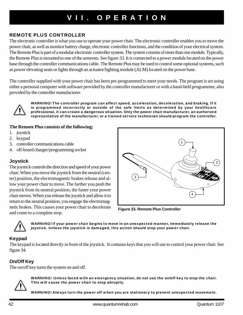
42 www.quantumrehab.com Quantum 1107
REMOTE PLUS CONTROLLERThe electronic controller is what you use to operate your power chair. The electronic controller enables you to move thepower chair, as well as monitor battery charge, electronic controller functions, and the condition of your electrical system.The Remote Plus is part of a modular electronic controller system. The system consists of more than one module. Typically,the Remote Plus is mounted to one of the armrests. See figure 33. It is connected to a power module located on the powerbase through the controller communications cable. The Remote Plus may be used to control some optional systems, suchas power elevating seats or lights through an actuator/lighting module (ALM) located on the power base.
The controller supplied with your power chair has been pre-programmed to meet your needs. The program is set usingeither a personal computer with software provided by the controller manufacturer or with a hand-held programmer, alsoprovided by the controller manufacturer.
WARNING! The controller program can affect speed, acceleration, deceleration, and braking. If itis programmed incorrectly or outside of the safe limits as determined by your healthcareprofessional, it can create a dangerous situation. Only the power chair manufacturer, an authorizedrepresentative of the manufacturer, or a trained service technician should program the controller.
The Remote Plus consists of the following:1. joystick2. keypad3. controller communications cable4. off-board charger/programming socket
JoystickThe joystick controls the direction and speed of your powerchair. When you move the joystick from the neutral (cen-ter) position, the electromagnetic brakes release and al-low your power chair to move. The farther you push thejoystick from its neutral position, the faster your powerchair moves. When you release the joystick and allow it toreturn to the neutral position, you engage the electromag-netic brakes. This causes your power chair to decelerateand come to a complete stop.
1
2
3
4
Figure 33. Remote Plus Controller
V I I . O P E R A T I O N
WARNING! If your power chair begins to move in an unexpected manner, immediately release thejoystick. Unless the joystick is damaged, this action should stop your power chair.
KeypadThe keypad is located directly in front of the joystick. It contains keys that you will use to control your power chair. Seefigure 34.
On/Off KeyThe on/off key turns the system on and off.
WARNING! Unless faced with an emergency situation, do not use the on/off key to stop the chair.This will cause the power chair to stop abruptly.
WARNING! Always turn the power off when you are stationary to prevent unexpected movement.

Quantum 1107 www.quantumrehab.com 43
Mode Key (Speed Settings)The mode key controls the speed settings. The RemotePlus speed settings range from 1 to 5. Typically, the slow-est speed setting is 1 and the fastest speed setting is 5. Thesettings are indicated by the number of lights that are lit onthe speed setting indicator.
NOTE: The speed settings are preset at the factory.If your Quantum Rehab Specialist changes the or-der of these settings, please make note of thesechanges. Contact your Quantum Rehab Specialist formore information.
To select a speed setting:1. Press the on/off key to power on the controller.2. Press the mode key once.3. To increase chair speed, push the joystick to the right. Each
time you push the joystick, you will increase the speed settingin the speed setting indicator.
4. To decrease chair speed, push the joystick to the left. Eachtime you push the joystick, you decrease the speed setting inthe speed setting indicator.
5. Once you select the desired speed setting, press the modekey once to keep the setting or push the joystick in theforward or reverse direction. The chair will resume operationat the selected speed.
NOTE: We recommend that the first few times you operate your power chair, you have your speed on theslowest setting until you become familiar with your new power chair.
Horn KeyThe horn key activates the horn.
Battery Condition MeterThe battery condition meter is a 10-segment illuminated display located in front of the joystick. When the lights are on, itindicates that there is power to the Remote Plus. The lights also indicate battery status, Remote Plus operational status, andelectrical system status.!!!!! Red, yellow, and green lights lit: Batteries charged; controller and electrical system OK.!!!!! Red and yellow lights lit: Charge batteries if possible; controller and electrical system OK.!!!!! Red lights only lit or slow flash: Charge batteries as soon as possible; controller and electrical system OK.!!!!! Rapid flash of lights: Indicates an error in the controller or the electrical system. See “Remote Plus Error Codes.”!!!!! Ripple up and down of lights: The joystick was not in the neutral position when the controller was turned on. If you
get “ripple up and down of lights,” turn off the controller and allow the joystick to return to the neutral position. Thenturn on the controller.
NOTE: If you still get “ripple up and down of lights,” contact your Quantum Rehab Specialist.
Figure 34. Remote Plus Keypad
V I I . O P E R A T I O N

44 www.quantumrehab.com Quantum 1107
NOTE: When the batteries approach a discharged state, the first red light will begin to slowly flash, remind-ing you the batteries need to be charged immediately!
Right/Left Turn Indicator Keys (Optional)The right/left turn indicator keys toggle either the left or right turn indicators. Press once to turn on and press again to turnoff. You can also turn off the selected turn indicator by pressing the opposite indicator key or the hazard key.
Light Key (Optional)The light key turns the headlights/taillights on and off independent of other indicators.
Hazard Key (Optional)The hazard key activates both turn indicators at the same time. You can only cancel this by pressing the hazard key again.
Power Accessories/Power Accessory Indicator (Optional)If your power chair is equipped with power accessories such as a power seat or power elevating leg rests, you can operatethem through the keypad. The power accessory indicator indicates the selected power accessory. Contact your QuantumRehab Specialist for more information.
Off-board Charger/Programming SocketThe off-board charger/programming socket is located on the front of the Remote Plus. If you use an off-board charger, thecharger current should not exceed 8 amps. Contact your Quantum Rehab Specialist for more information.
WARNING! Only chargers with Neutrik NC3MX plugs should be connected to the off-board charger/programming socket. See your Quantum Rehab Specialist for more information.
Controller Communications CableThe controller communications cable provides the Remote Plus with a connection to the power module.
Sleep ModeYour Remote Plus controller has a sleep mode feature. Sleep mode is a built-in circuit that automatically shuts off the mainpower if the joystick is not moved in any direction for approximately five minutes. The battery condition meter lights on thekeypad indicate sleep mode by blinking once every five seconds. To restore power and continue, push the on/off keytwice.
Thermal RollbackThe Remote Plus is equipped with a thermal rollback circuit. This circuit monitors the temperature of the motors, powermodule, and remote. In the event that any of them become excessively hot (above 122° F), motor voltage is reduced. Forevery degree above 122° F, the voltage is reduced by 5 volts. This reduces your power chair’s speed and allows theelectrical components to cool down. When the temperature returns to a safe level, your power chair resumes its normalspeed.
V I I . O P E R A T I O N

Quantum 1107 www.quantumrehab.com 45
Remote Plus Error CodesIn addition to indicating the current state of battery charge, the battery condition meter can also indicate possible problemswith your power chair’s electrical system. If any of the battery condition meter lights are flashing rapidly, the controller maybe indicating an error. Error codes are displayed as a number of flashing lights. For instance, if the first light is flashingrapidly, the battery voltage is nearly depleted. The table below identifies the individual error codes, probable causes, andpossible solutions. If you get one of these error codes, contact your Quantum Rehab Specialist.
FLASHING LIGHTS DIAGNOSIS SOLUTION10 High Battery Voltage Check batteries.9 Solenoid Brake Fault Check motor/brake wiring.8 Possible Controller Fault See Quantum Rehab Specialist.7 Possible Joystick Fault See Quantum Rehab Specialist.6 Inhibit Active Unplug charger. Check connections.5 Right Motor Wiring Fault Check right motor wiring.4 Right Motor Disconnected Check right motor wiring.3 Left Motor Wiring Fault Check left motor wiring.2 Left Motor Disconnected Check left motor wiring.1 Low Battery Voltage Check batteries/battery wiring.
V I I . O P E R A T I O N

46 www.quantumrehab.com Quantum 1107
THE MICRODRIVE CONTROLLERThe electronic controller is what you use to operate your power chair. It takes the battery voltage and sends it to theappropriate system. The electronic controller also enables you to monitor battery charge, electronic controller functions,and the condition of your electrical system. Also, it may be used to control some optional systems such as power elevatingseats and lights. The Microdrive electronic control system is a modular system. The electronics necessary to operate yourpower chair are contained in several modules located on different parts of your power chair. Typically, the MicrodriveController is mounted to one of the armrests. See figure 35. The other components are located on or inside the powerbase.
The controller supplied with your power chair has been pre-programmed to meet your needs. The program is set usingeither a personal computer with software provided by the controller manufacturer or with a hand-held programmer, alsoprovided by the controller manufacturer.
WARNING! The controller program can affect speed, acceleration, deceleration, and braking. If itis programmed incorrectly or outside of the safe limits as determined by your healthcareprofessional, it can create a dangerous situation. Only the power chair manufacturer, an authorizedrepresentative of the manufacturer, or a trained service technician should program the controller.
The Microdrive Controller consists of:1. joystick2. display pad3. mode switch4. on/off switch5. speed control knob6. joystick interface module7. off-board charger/programming socket
Figure 35. Microdrive Controller with Joystick InterfaceModule
JoystickThe joystick controls the direction and speed of your powerchair. When you move the joystick from the neutral (center)position, the electromagnetic brakes release and allow thepower chair to move. The farther you push the joystick fromits neutral position, the faster the power chair moves. Whenyou release the joystick and allow it to return to the neutralposition, the electromagnetic brakes engage and the powerchair comes to a complete stop.
WARNING! If your power chair begins tomove in an unexpected manner,immediately release the joystick. Unlessthe joystick is damaged, this actionshould stop your power chair.
V I I . O P E R A T I O N

Quantum 1107 www.quantumrehab.com 47
Profile and Speed IndicatorThe profile and speed indicator is a 5-segment illumi-nated display that indicates speed setting as well as driveprofile.
Actuator IndicatorThe actuator indicator is a 4-segment illuminated dis-play that indicates power recline, power tilt, power legrest, and power elevating seat actuator modes.
Joystick Interface ModuleThe joystick interface module provides a means to enableor disable the horn button, mode switch, on/off switch,and speed adjustment dial.
NOTE: When a toggle switch is set to “J/S,” thejoystick has control of a particular function. Whenthe toggle switch is set to “Local,” control of thisfunction is disabled at the joystick.
Display PadThe display pad is located directly in front of the joystick. It contains the horn key, battery condition meter, profile and speedindicator, and the actuator indicator. See figure 36.
Horn KeyThe horn key activates the horn.
Battery Condition MeterThe battery condition meter is a 10-segment illuminated display that indicates that the Microdrive is powered on and alsogives the status of the batteries, the controller, and the power chair electrical system.! Red, yellow, and green lights lit: Batteries charged; controller and electrical system OK.! Red and yellow lights lit: Charge batteries if possible; controller and electrical system OK.! Red lights only lit or slow flash: Charge batteries as soon as possible; controller and electrical system OK.! Rapid flash of lights: Indicates a fault in the controller or the electrical system. See “Error Codes.”! Ripple side to side of lights: The joystick was not in the neutral position when the controller was turned on. If you
get “ripple side to side of lights,” turn off the controller, allow the joystick to return to the neutral position, then turn onthe controller.
NOTE: If you still get “ripple side to side of lights,” contact your Quantum Rehab Specialist.
NOTE: When the batteries approach a discharged state, the first red light will begin to slowly flash, reminding you thebatteries need to be charged immediately!
Figure 36. Microdrive Display Pad
V I I . O P E R A T I O N

48 www.quantumrehab.com Quantum 1107
Drive Profile SelectionYour Microdrive controller may be programmed for more than one drive profile that allows the system to be customtailored to your environment.
To select a profile setting:1. Use the on/off switch to power on the chair and the controller.2. Press the mode button.3. Move the joystick left or right to select the desired drive profile. Each of the LEDs indicate a separate profile.
NOTE: The system can be programmed with 5 different profiles.
Speed AdjustmentThe Microdrive controller provides a speed control knob to control the speed of the power chair.
To change the speed:1. Use the on/off switch to power on the chair and the controller.2. To increase your speed, turn the speed control knob clockwise.3. To decrease your speed, turn the speed control knob counterclockwise.
Off-board Charger/Programming SocketUsed for off-board charger connections and joystick programming. Off-board chargers should not exceed 8 amps.Contact your Quantum Rehab Specialist for more information.
Sleep ModeThe Microdrive controller offers a sleep mode feature which will shut off the main power if the joystick remains stationaryfor a period of five minutes. The battery condition meter will indicate sleep mode by blinking once every five seconds. Torestore power and resume operation of the chair, flip the on/off switch twice.
Thermal RollbackThe Microdrive controller is equipped with a thermal rollback circuit which monitors the temperature of the chair’s motorsand controller. If either exceeds 122° F, the controller reduces the motor voltage by 5 volts for every degree over. Thisreduces the chair’s speed and allows a cool down period. Once the temperature returns to a safe level, the chair willresume normal operation.
Error CodesIn addition to indicating the current state of battery charge, the battery condition meter can also indicate possible problemswith your power chair’s electrical system. If any of the battery condition meter lights are flashing rapidly, the controller may beindicating an error. Error codes are displayed as a number of flashing lights. For instance, if the first light is flashing rapidly, thebattery voltage is nearly depleted. The table below identifies the individual error codes, probable causes, and possible solu-tions. If you get one of these error codes, contact your Quantum Rehab Specialist.
V I I . O P E R A T I O N

Quantum 1107 www.quantumrehab.com 49
FLASHING LIGHTS DIAGNOSIS SOLUTION
10 High Battery Voltage Check batteries.
9 Solenoid Brake Fault Check motor/brake wiring.
8 Possible Controller Fault See Quantum Rehab Specialist.
7 Possible Joystick Fault See Quantum Rehab Specialist.
6 Inhibit Active Unplug charger. Check connections.
5 Right Motor Wiring Fault Check right motor wiring.
4 Right Motor Disconnected Check right motor wiring.
3 Left Motor Wiring Fault Check left motor wiring.
2 Left Motor Disconnected Check left motor wiring.
1 Low Battery Voltage Check batteries/battery wiring.
V I I . O P E R A T I O N

50 www.quantumrehab.com Quantum 1107
V I I I . C A R E A N D M A I N T E N A N C E
CARE AND MAINTENANCEYour power chair is a sophisticated device. Like any motorized vehicle, it requires routine maintenance checks. You canperform some of these checks, but others require assistance from your Quantum Rehab Specialist. Preventive maintenanceis very important. If you follow the maintenance checks in this section as scheduled, you can help ensure that your powerchair gives you years of trouble-free operation. If you have any doubt as to your power chair’s care or operation, contactyour Quantum Rehab Specialist.
WARNING! Prevent injury. Do not service the power chair when the seat is occupied.
Your power chair, like most electrical equipment, is susceptible to damage from the elements. Avoid damp areas ofany kind.
WARNING! Direct exposure to water or dampness could cause the power chair to malfunctionelectronically and mechanically. Water can cause electrical components to corrode and the chair’sframe to rust.
Should your power chair come in contact with water:1. Dry your power chair as thoroughly as possible with a towel.2. Allow your power chair to sit in a warm, dry place for 12 hours to allow unseen water to evaporate.3. Check the joystick operation and the brakes before using your power chair again.4. If any inconsistencies are found, take your power chair to your Quantum Rehab Specialist.
Temperature! Some of the parts of your power chair are susceptible to extreme changes in temperature. Always keep your power
chair between the temperatures of 18° F and 122° F.! In extremely cold temperatures the batteries may freeze. The specific temperature at which they freeze depends on a
number of factors, such as battery charge, usage, and composition of the batteries (e.g., AGM or Gel-Cell).! Temperatures above 122° F may cause your power chair to operate at a reduced speed. This reduced speed is a
safety feature built into the controller that helps prevent damage to the motor and other electrical components. See VII.“Operation.”
General Guidelines! Avoid knocking or bumping the controller, especially the joystick.! Avoid prolonged exposure of your power chair to extreme conditions, such as heat, cold, or moisture.! Keep the controller clean.! Check all connectors to ensure that they are all tight and secured properly.! Make sure the drive tires are inflated to 35 psi (2.4 bar) if equipped with pneumatic tires.
WARNING! Overinflating tires can cause them to explode and can result in personal injury.
WARNING! Do not use a high pressure hose to inflate your tires.
! Use a rubber conditioner on the tire sidewalls to help preserve them.
WARNING! Never use a rubber conditioner on the tread area of the tires; doing so may make thetires slippery and cause your power chair to skid.

Quantum 1107 www.quantumrehab.com 51
V I I I . C A R E A N D M A I N T E N A N C E
! The body shroud has been sprayed with a clear sealant coating. You can apply a light coat of car wax to help it retainits high-gloss appearance.
! Check all electrical connections. Make sure they are tight and are not corroded.! All wheel bearings are prelubricated and sealed. They require no subsequent lubrication.
Daily Checks! With the controller turned off, check the joystick. Make sure it is not bent or damaged and that it returns to the neutral
position when you release it. Check the rubber boot around the base of the joystick for damage. Visually inspect theboot. Do not handle or try to repair it. See your Quantum Rehab Specialist if there is a problem.
! Visually inspect the controller cable. Make sure that it is not frayed, cut, or has any wires exposed. See your QuantumRehab Specialist if there is a problem.
! Check for flat spots on solid tires. Flat spots could adversely affect stability.
Weekly Checks! Disconnect and inspect the controller cable connector from the power base. Look for corrosion. Contact your Quantum Rehab
Specialist if necessary.! Ensure that all parts of the controller system are securely fastened to your power chair. Do not overtighten any screws.! Check for proper tire inflation. There should be 35 psi (2.4 bar) in each tire if equipped with pneumatic tires. If a tire does not hold
air, see your Quantum Rehab Specialist for replacement of the tube.! Check the brakes. This test should be carried out on a level surface with at least three feet of clearance around your power chair.
To check the brakes:1. Turn on the controller and turn down the speed level of your power chair.2. After one second, check the battery condition meter. Make sure that it remains on.3. Slowly push the joystick forward until you hear the electromagnetic brakes click. Immediately release the joystick. You
must be able to hear each electromagnetic brake operating within a few seconds of joystick movement. Repeat this testthree times, pushing the joystick backward, then left, and then right.
Monthly Checks! Check that the anti-tip wheels do not rub the ground when you operate the power chair. Adjust them as necessary. See
V. “Comfort Adjustments.”! Check for extreme wear on the anti-tip wheels. Replace them as necessary.! Check for drive tire wear. See your Quantum Rehab Specialist for repair.! Check the caster wheels for wear. Replace them as necessary.! Check the caster forks for damage or fluttering which indicates that they may need to be adjusted or have the bearings
replaced. See your Quantum Rehab Specialist for repair.! Keep your power chair clean and free of foreign material, such as mud, dirt, hair, food, drink, etc.
Yearly ChecksTake your power chair to your Quantum Rehab Specialist for yearly maintenance. This helps ensure that your power chairis functioning properly and helps prevent future complications.
StorageYour power chair should be stored in a dry place, free from temperature extremes. When storing, disconnect the batteriesfrom the power chair. See VI. “Batteries and Charging.”

52 www.quantumrehab.com Quantum 1107
V I I I . C A R E A N D M A I N T E N A N C E
WARNING! If you fail to store the unit properly, the frame can rust and the electronics can bedamaged.
Disposal of Your Power ChairYour power chair must be disposed of according to applicable local and national statutory regulations. Contact your localwaste disposal agency or Quantum Rehab Specialist for information on proper disposal of power chair packaging, metalframe components, plastic components, electronics, and batteries.
Cleaning and Disinfection! Use a damp cloth and mild, non-abrasive cleanser to clean the plastic and metal parts of your power chair. Avoid usingproducts that may scratch the surface of your power chair.! If necessary, clean your product with an approved disinfectant. Make sure the disinfectant is safe for use on yourproduct before application.
WARNING! Prevent personal injury and product damage! Follow all safety instructions for theproper use of the disinfectant before applying it to your product.
WARNING! Never hose off your power chair or place it in direct contact with water. Your powerchair has a painted, ABS plastic body shroud that allows it to be easily wiped clean with a dampcloth.
WARNING! Never use any chemicals to clean a vinyl seat, as they may cause the seat to becomeslippery or dry out and crack. Use soapy water and dry the seat thoroughly.
Wheel ReplacementIf you have pneumatic tires and you have a flat tire, you can replace the tube. If your chair is equipped with a solid tireinsert, then you must replace the whole wheel assembly. Replacement tires, tubes, and wheel assemblies are readilyavailable through your Quantum Rehab Specialist.
WARNING! To avoid possible injury, be sure that the controller’s power is turned off and thepower chair is not in freewheel mode before performing this procedure.
WARNING! Completely deflate pneumatic tires before attempting repair.
Figure 37. Quantum 1107 Drive Wheel
DRIVE WHEELNUT
Figure 38. Quantum 1107 Drive Wheel Disassembled
DRIVE WHEEL WASHER
AXLESLOT
AXLE KEY
FRONT RIM HALF
WASHERS
TUBE
TIRE WHEEL HUB
NUTS
REAR RIMHALF

Quantum 1107 www.quantumrehab.com 53
V I I I . C A R E A N D M A I N T E N A N C E
Follow these easy steps for a quick and safe repair for both pneumatic and solid tires:1. Turn off the power to the controller.2. Set the power chair up on blocks.3. If you are changing a pneumatic tire, completely deflate it before removing the wheel.4. Remove the drive wheel nut and washer from the axle. See figure 37.5. Pull the wheel off the axle.6. Remove the nuts and washers from the wheel hub and separate the rim halves. See figure 38.7. Remove the old tube from the pneumatic tire and replace it with a new tube or replace the entire assembly if it is a solid tire.8. Reassemble the rim halves and reinstall the nuts and washers to the wheel hub.9. Slide the wheel back onto the axle. Make sure that the key is in the axle slot.
Figure 39. Battery Boxes
REAR BOX
FRONT BOX
MAIN CIRCUIT BREAKER
Battery ReplacementA battery wiring diagram is printed on a decal located insidethe battery box lid. See VI. “Batteries and Charging” for cor-rect battery specifications.
WARNING! Prevent injury. Do not replacebattery when seat is occupied.
WARNING! Battery posts, terminals, andrelated accessories contain lead and leadcompounds. Wear goggles and gloveswhen handling batteries and wash handsafter handling.
WARNING! Power chair batteries areheavy. See specifications table. If you areunable to lift that much weight, be sureto get help. Lifting beyond your capacitycan result in personal injury.
WARNING! Prevent in jur y and /orequipment damage! Do not mix or matchnew and old batteries. If you encounter asituation where one battery needs to bereplaced, then replace both batteries.Refer to specification table in this manualsupplied with battery charger forrecommended type and capacities.
To replace the batteries:1. Turn off the power to the controller.2. Make sure that the power chair is in drive mode. See III.
“Your Power Chair.”3. Remove the battery boxes. See IV. “Assembly/Disassembly.”4. Disconnect the wiring harness from the batteries.5. Remove the batteries from the battery boxes.6. Place new batteries in the battery boxes. See figure 39.
10. Reinstall the drive wheel nut and washer onto the axle and tighten.11. Inflate the pneumatic tires to 35 psi (2.4 bar) if equipped with pneumatic tires.12. Remove the power chair from the blocks.

54 www.quantumrehab.com Quantum 1107
V I I I . C A R E A N D M A I N T E N A N C E
7. Reconnect the battery harnesses according to the bat-tery wiring diagram label. See figure 40.
WARNING! Prevent injury. Make sure youtighten the fasteners so that the connectionsare secure.
8. Reinstall the battery boxes onto the power base. Makesure that the battery box latches are in the up (locked)position.
9. Charge the batteries. See VI. “Batteries and Charging.”
When to See Your Quantum Rehab Specialist for ServiceThe following symptoms could indicate a serious problem with your power chair. If necessary, contact your QuantumRehab Specialist. When calling, have the model number, serial number, nature of the problem, and the error code ifavailable.! Motor noise! Frayed harnesses! Cracked or broken connectors! Uneven wear on any of the tires! Jerky motion! Pulling to one side! Bent or broken wheel assemblies! Does not power up! Powers up, but does not move
Corrective MaintenanceIf the battery condition meter does not light up when you turn on the power:! Check the harness connections. Make sure they are tight.! Check the circuit breaker. Reset it if necessary.! Check the battery connections.
If the above conditions prove normal, you can load test the batteries with a battery load tester. These testers are availableat automotive parts stores. Disconnect both batteries before load testing and follow the directions that come with the loadtester. If either one of the batteries fails the load test, replace both of them. If your power chair still does not power up,contact your Quantum Rehab Specialist.
Figure 40. Battery Wiring Diagram Label

Quantum 1107 www.quantumrehab.com 55
I X . W A R R A N T Y
LIFETIME LIMITED WARRANTYFor the lifetime of your power chair from the date of purchase, Pride will repair or replace at our option to the originalpurchaser, free of charge, any of the following parts found upon examination by an authorized representative of Pride to bedefective in material and/or workmanship:
Structural frame components, including:! Main Frame ! Fixed-position seat post
TWO-YEAR LIMITED WARRANTYFor two (2) years from the date of purchase, Pride will repair or replace at our option to the original purchaser, free ofcharge, any of the following parts found upon examination by an authorized representative of Pride to be defective inmaterial and/or workmanship:
Electronic components, including: Main frame assemblies, including:! Charger Assembly ! Anti-tip forks ! Caster forks! Controller ! Caster beam ! Metal seat framing! Joystick
Other components, including:! Foot riggings ! Electrical Harness ! Foot rigging mounting brackets
18-MONTH LIMITED WARRANTYFor eighteen (18) months from the date of purchase, Pride will repair or replace at our option to the original purchaser, freeof charge, any of the following parts found upon examination by an authorized representative of Pride to be defective inmaterial and/or workmanship:
! Motor/gearbox assembly ! Power seat actuator
ONE-YEAR LIMITED WARRANTYFor one (1) year from the date of purchase, Pride will repair or replace at our option to the original purchaser, free ofcharge, any of the following parts found upon examination by an authorized representative of Pride to be defective inmaterial and/or workmanship:
! Accessories ! Brakes (electronic function ONLY)
SIX-MONTH LIMITED WARRANTYFor six (6) months from the date of purchase, Pride will repair or replace at our option to the original purchaser, free ofcharge, any of the following parts found upon examination by an authorized representative of Pride to be defective inmaterial and/or workmanship:
! Bearings and bushings ! Plastic components, except body
The battery is covered by a separate six-month warranty, provided by the battery manufacturer. The batteries are notwarranted by Pride.

56 www.quantumrehab.com Quantum 1107
I X . W A R R A N T Y
RECONDITIONED UNITS WARRANTYAll reconditioned units are covered by a six-month warranty from Pride effective from the date of purchase.
WARRANTY EXCLUSIONSThis warranty does not extend to those items which may require replacement due to normal wear and tear.! ABS Plastic shrouds ! Motor brushes ! Upholstery and seating! Brake Pads ! Tires and tubes ! Fuses/Bulbs
! Circumstances beyond the control of Pride! Labor, service calls, shipping, and other charges incurred for repair of the product, unless specifically authorized, IN
ADVANCE, by Pride Mobility Products Corporation! Repairs and/or modifications made to any part without specific consent from Pride
Exclusions also include components with damage caused by:! Contamination! Abuse, misuse, accident, or negligence! Battery fluid spillage or leakage! Commercial use, or use other than normal! Improper operation, maintenance, or storage
NOTE: Gradual deterioration in performance because the battery has been left in a discharged state, left incold conditions for an extended period of time, or worn out through heavy use is not covered.
SERVICE CHECKS AND WARRANTY SERVICEWarranty service must be performed by a Quantum Rehab Specialist. Do not return faulty parts to Pride without priorwritten authorization. All transportation costs and shipping damage incurred while submitting parts for repair or replacementare the responsibility of the purchaser.
Failure to follow the instructions, warnings, and notes in the owner’s manual and those located on your Pride product canresult in personal injury or product damage and will void Pride’s product warranty.
There is no other express warranty.
IMPLIED WARRANTIESImplied warranties, including those of merchantability and fitness for a particular purpose, are limited to one (1) year fromthe date of purchase and to the extent permitted by law. Any and all implied warranties are excluded. This is the exclusiveremedy. Liabilities for consequential damages under any and all warranties are excluded.
Some states do not allow limitations on how long an implied warranty lasts or do not allow the exclusion of limitationincidental or consequential damages. The above limitation or exclusion may not apply to you.
This warranty gives you specific rights, and you may also have other rights which vary from state to state.
Please fill out and return the product registration card to Pride. This will aid Pride in providing the best possible technicaland customer service.

Quantum 1107 www.quantumrehab.com 57
N O T E S

58 www.quantumrehab.com Quantum 1107
N O T E S

Q u a l i t y C o n t r o l - M o d e l 1 400
Thank you formaking theQuantum 1107your choice inpower chairs.
We havethoroughlyinspected yourQuantum 1107.The followingcheck marksindicate that ithas been tested,driven, andinspected.
#1In Quality
Quality Control - Quantum 1107
Pride keeps a more detailed report on file at the factory.
Date Inspected
Inspector
*infmanu2882*
Inclusion of all Parts
Joystick Serial Number
Controller Serial Number
Left Motor Serial Number
Right Motor Serial Number
Serial #
Fit and Finish
Performance