OWNER’S MANUAL MINI PORTABLE SPLIT AIR …...MINI PORTABLE SPLIT AIR CONDITIONER F001-MP8K...
20
FA-UM-MINI-5176 - v1.0 - 01/2019 © Copyright, ForestAir, 2018 IMPORTANT : Please read this manual carefully before running this unit, and save it for future reference. OWNER’S MANUAL MINI PORTABLE SPLIT AIR CONDITIONER F001-MP8K F001-10KR/A
Transcript of OWNER’S MANUAL MINI PORTABLE SPLIT AIR …...MINI PORTABLE SPLIT AIR CONDITIONER F001-MP8K...

FA-UM-MINI-5176 - v1.0 - 01/2019 © Copyright, ForestAir, 2018
IMPORTANT : Please read this manual carefully before running this unit, and save it for future reference.
OWNER’S MANUALMINI PORTABLE SPLIT AIR CONDITIONER
F001-MP8KF001-10KR/A


3
Air conditioners, heat pumps and dehumidifiers are products of high value. ln order to ensure your lawful rights and interests, if you are not familiar with the installation of this type of appliance, please have a have a professional install the product for you. This instruction manual is the universal-purpose version for the MINI air conditioner manufactured by ForestAir. The appearance of the unit that you have purchased may differ from the ones seen in this manual, however it does not change the basic guidelines on how to operate this air conditioner.
To ensure satisfactory operation for many years to come, this manual should be read carefully before using the appliance. After reading, store in a safe place. Please refer to the manual for questions on use or in the event that any irregularities occur.
1.0. SAFETY INSTRUCTIONS ........................................................................................................................4
2.0. COMPONENTS OVERVIEW ...................................................................................................................5
3.0. INSTALLATION GUIDE3.1. Installation recommendations ................................................................................................................63.2. Wall mounting the indoor unit (optional) ................................................................................................73.3. Installing the outdoor unit .......................................................................................................................73.4. Assembling and installing the window kit ..............................................................................................8
4.0. OPERATION GUIDE4.1. Display screen, control panel and remote control overview ...............................................................104.2. Button functions ...................................................................................................................................114.3. Remote control operation ....................................................................................................................124.4. Other functions .....................................................................................................................................12
5.0. CARE & MAINTENANCE5.1. Cleaning the appliance ........................................................................................................................135.2. Water drainage .....................................................................................................................................14
6.0. TROUBLESHOOTING6.1. Common issues ...................................................................................................................................156.2. Error codes ...........................................................................................................................................16
7.0. WARRANTY .............................................................................................................................................17
TABLE OF CONTENT
FOREWORD
Electrical products should be properly disposed. Please recycle where facilities exist. Check with your local authority or retailer for recycling.

4
1.0. SAFETY INSTRUCTIONS
Read the following safety instructions before installing the unit or doing service work.
To reduce the risk of fire, electric shock, or personal injury when using this appliance, follow these basic safety precautions.
PRECAUTIONS▪ The air conditioner is suitable for residential indoor use only. ▪ Do not use the product for any purpose other than described in this user manual.▪ Follow local grid interconnection rules while installing the air conditioner and ensure that it is
properly grounded. If you have any question on electrical installation, follow the instructions of the manufacturer, and if necessary, ask a professional electrician to install it.
▪ After the air conditioner is installed, ensure that the power plug is intact and firmly inserted into the electric outlet. Arrange the power cord so that no one accidentally trips over it or pulls it out of the outlet.
▪ Keep the product upright at all times. Failure do to so could lead to malfunctions.▪ Do not put any object into the air inlet or outlet of the air conditioner. Keep the air inlet and outlet
free from obstructions. ▪ When installing the condensation hose, ensure that it is properly connected and not twisted or bent.▪ Keep the appliance away from gasoline, flammable gas, stoves and other heat sources. ▪ Do not disassemble, overhaul or modify the air conditioner arbitrarily, it could cause a malfunction
or even personal injury and material damage. To avoid danger, if a failure occurs, ask the manufacturer or professionals to repair it.
▪ Do not install and use the air conditioner in humid or dusty environments.▪ Do not direct the airflow on children, elderly or sick people, pets or house plants for extended
periods of time. This could affect their health negatively. ▪ To disconnect, grip the plug and pull from electric outlet. Never yank the cord to unplug it.• Do not operate the appliance with a damaged cord or plug or after it has malfunctioned, has been
dropped or damaged in any manner.• If the power cord is damaged, it must be replaced by a qualified technician in order to prevent
electric hazards or injuries.▪ Do not use insecticide sprays or other flammable substances near the air conditioner.▪ Do not place objects on top of the unit.▪ Always unplug the appliance from the power outlet before servicing.▪ Do not wipe or wash the air conditioner with wax or chemical solvents such as gasoline or alcohol.
When cleaning the appliance, make sure to disconnect the power supply.▪ This appliance is not intended for use by persons (including children) with reduced physical,
sensory or mental capabilities, or lack of experience and knowledge, unless they have been given supervision or instruction concerning use of the appliance by a person responsible for their safety. Children should be supervised to ensure that they do not play with the appliance.
WARNING : Can cause serious personal injury or death.
CAUTION : Can lead to injury or structural damage under some conditions.

5
2.0. COMPONENTS OVERVIEW
INDOOR UNIT – FRONT VIEW INDOOR UNIT – REAR VIEW
1 Front panel 6 Remote control 11 Drainage hose2 Air filter 7 Coolant lines 12 Back compartment cover3 Handle 8 Remote control holder 13 Handle4 Control panel 9 Mounting slots 14 Air outlet (warm air)5 Air outlet (cool air) 10 Power cord 15 Condensation port
1
2
6
5
7
3
4
11 12
10
98
OUTDOOR UNIT
13
14 7
15
Condensation hose
Wing nut, T-bolt and washer (3)
Screw and anchor (4)
Rubber connectorWindow slider kit (4 panels)
A B1 B2 C

6
3.0. INSTALLATION GUIDE
█ 3.1. INSTALLATION RECOMMENDATIONS
Note : Since cool air is denser than warm air and moves downwards, it is recommended that the indoor unit be installed in an elevated area in order to obtain maximum efficiency.
FIG. 1 – Place the indoor unit in an elevated area
INDOOR UNIT▪ Do not install the indoor unit in a sloped setting.▪ Do not install the indoor unit in direct sunlight.▪ Do not install in places with open flames or flammable gas.▪ Do not use extension cords, etc. Only plug the indoor unit into a grounded wall outlet.▪ Install in clear area without any obstructions nearby.▪ Avoid installing the indoor unit in damp areas.
OUTDOOR UNIT
▪ Never install the outdoor unit in a place where the product is likely to fall.▪ Make sure to drain the outdoor unit with the condensation hose.▪ For optimal performance, do not install the outdoor unit in direct sunlight.▪ Do not install the outdoor unit near open flames or by flammable gas.▪ Do not install the outdoor unit in areas of extreme wind conditions.▪ Install the unit where there will be no obstruction to the air inlet and outlet.▪ Ensure that the unit is not installed where it can be a source of nuisance for neighbours.▪ If needed, install on a solid and steady structure.

7
3.0. INSTALLATION GUIDE
█ 3.2. WALL MOUNTING THE INDOOR UNIT (OPTIONAL)
Notes :▪ Choose a mounting location situated next to a window or patio door as the coolant lines must be run
through a window to connect the indoor and outdoor unit.▪ Using a stud detector for installation into wall studs may be desired for more secure mounting.
1. Choose a suitable location on the wall for mounting the unit.2. Measure between the mounting slots on the back of the unit.3. Mark locations on the wall according to the slots.4. Use a drill to make 4 holes at each of the marks.5. Insert the provided anchors into the wall.6. Add the screws into their anchors making sure a length of 4 to 9 mm (~1/4 in) is left out of the wall.7. Install the indoor unit onto the wall making sure the mounting slots slide over the screws.8. Check to ensure the indoor unit is securely installed.
FIG. 2 – Taking measurements
L
H
FIG. 3 – Drilling 4 holes in the wall
Screw holes
Wall
FIG. 4 – Installing the anchors & screws
Minimum 4 - 9 mm (~1/4 in)
ScrewAnchor
Wall
█ 3.3. INSTALLING THE OUTDOOR UNIT
1. In order to let off exhaust air adequately, the outdoor unit should be placed on a level, stable surface, with at least 30 cm (12 in) of clearance between it, the walls and surrounding objects.
2. Connect the provided condensation hose to the condensation port on the side of the unit. Lead the hose to a bucket or an area where the excess water can be drained properly.
FIG. 5 – Clearance space
30 cm (12 in)
Front of the unit
FIG. 6 – Connecting the condensation hose
Condensation port
Condensation hose

8
3.0. INSTALLATION GUIDE
█ 3.4. ASSEMBLING AND INSTALLING THE WINDOW KIT
Your window kit has been designed to fit most standard vertical and horizontal window, and patio door applications, however it may be necessary for you to improvise or modify certain aspects of the installation for certain types of window. Start by measuring the window opening you have available and, using the table below, determine which slider panels you will be needing.
PanelWindow opening A B1 C B2
65 cm (25 ½ in) ●
65 – 127 cm (24 ⅜ – 50 in) ● ●
127 – 189 cm (24 ⅜ – 74 ⅜ in) ● ● ●
189 – 250 cm (74 ⅜ – 98 ⅜ in) ● ● ● ●
A B1 B2 C
59 cm
(23
1/4
in)
65 cm
(25
½ in
)
62 cm
(24
⅜ in
)
59 cm
(23
¼ in
)
Notes :▪ If the window opening is less than 65 cm (25 ½ in), the minimum length of the panel A, shorten the
panel by cutting off the exceeding length in order to fit the window opening.▪ Never cut out the hole from panel A.
Assembling the Window Panels
The following instructions covers the assembly of all 4 panels. Adjust as required.
1. Insert a T-bolt into the end of panel A opposite to the coolant lines opening.2. Slide panel B1 onto the end of panel A, making sure the T-bolt is simultaneously inserted onto the
central groove, then use the wing nut and washer to secure both panels together.3. Insert a T-bolt into one end of panel C.4. Slide panel B1 onto the end of panel C, making sure the T-bolt is simultaneously inserted onto the
central groove, then use the wing nut and washer to secure the sections together.5. Insert a T-bolt into the other end of panel C.6. Slide panel B2 onto the end of panel C, making sure the T-bolt is simultaneously inserted onto the
central groove, then use the wing nut and washer to secure the sections together.
T-boltHole
FIG. 7 – Insert T-bolt from the back
T-bolt
Central groove
FIG. 8 – Insert into central groove
Wing nut and washer
FIG. 9 – Secure with wing nut

9
3.0. INSTALLATION GUIDE
7. Make sure all panels are connected as seen in the illustration below.
Panel A
Opening for coolant lines
Panel B1 Panel C Panel B2
FIG. 10 – Four panel window kit assembly
Finishing the Installation
1. Insert the coolant lines into the side of the rubber connector then fit the connector into panel A making sure the notch is in place.
FIG. 11 – Fitting the coolant lines through the window kit
Connector Panel A
Coolant lines Final assemly
2. Install the assembled kit into the window opening and push the window nearly closed to secure it in place. Use the nuts to adjust as needed.
FIG. 12 – Installation in sliding window FIG. 13 – Installation in hung window
10
4.0. OPERATION GUIDE
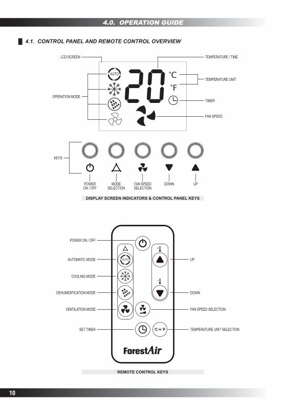
█ 4.1. CONTROL PANEL AND REMOTE CONTROL OVERVIEW
DISPLAY SCREEN INDICATORS & CONTROL PANEL KEYS
TIMER
FAN SPEED
TEMPERATURE UNIT
TEMPERATURE / TIME
OPERATION MODE
KEYS
LCD SCREEN
POWER ON / OFF
MODE SELECTION
FAN SPEED SELECTION
DOWN UP
UP
DOWN
FAN SPEED SELECTION
TEMPERATURE UNIT SELECTION
REMOTE CONTROL KEYS
AUTOMATIC MODE
POWER ON / OFF
COOLING MODE
DEHUMIDIFICATION MODE
VENTILATION MODE
SET TIMER
11
4.0. OPERATION GUIDE
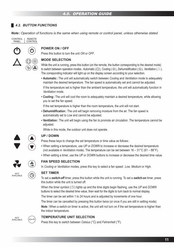
█ 4.2. BUTTON FUNCTIONS
Note : Operation of functions is the same when using remote or control panel, unless otherwise stated.
CONTROL PANEL
REMOTE CONTROL
POWER ON / OFFPress this button to turn the unit ON or OFF.
MODE SELECTIONWhile the unit is running, press this button (on the remote, the button corresponding to the desired mode) to switch between operation modes : Automatic ( ), Cooling ( ), Dehumidification ( ), Ventilation ( ). The correponding indicator will light up on the display screen according to your selection.▪ Automatic : The unit will automatically switch between Cooling and Ventilation mode to adequately
maintain the desired temperature. The fan speed is automatically set and cannot be adjusted. If the temperature set is higher than the ambient temperature, the unit will automatically function in
Ventilation mode.▪ Cooling : The unit will cool the room to adequately maintain a desired temperature, while allowing
you to set the fan speed. If the set temperature is higher than the room temperature, the unit will not start.▪ Dehumidification : The unit will begin removing moisture from the air. The fan speed is
automatically set to Low and cannot be adjusted. ▪ Ventilation : The unit will begin using the fan to promote air circulation. The temperature cannot be
adjusted. While in this mode, the outdoor unit does not operate.
UP / DOWNPress these keys to change the set temperature or time value as follows :▪ When setting a temperature, use UP or DOWN to increase or decrease the desired temperature
(not available in Ventilation mode). The temperature can be set between 16 – 31°C (61 – 88°F).▪ When setting a timer, use the UP or DOWN buttons to increase or decrease the desired time value.
FAN SPEED SELECTIONIn Cooling or Ventilation modes, press this key to select a fan speed : Low, Medium or High.
SET TIMERTo set a switch-off timer, press this button while the unit is running. To set a switch-on timer, press this button while the unit is turned off.When the timer symbol ( ) lights up and the time digits begin flashing, use the UP and DOWN buttons to select the desired time value, then wait for the digits to turn back to normal display.The timer can be set within 1 to 24 hours and is adjusted by increments of one hour.The timer can be cancelled by pressing this button twice (or once if you are still in setting mode).Note : When a switch-on timer is active, the unit will not turn on if the set temperature is higher than the indoor temperature.
TEMPERATURE UNIT SELECTIONPress this key to switch between Celsius (°C) and Fahrenheit (°F).
NOT AVAILABLE
NOT AVAILABLE

12
4.0. OPERATION GUIDE
█ 4.3. REMOTE CONTROL OPERATION
Before using the remote, remove the protective insulation film covering the battery by pulling on the tab.
FIG. 14 – Pull the tab to remove film
Tab
Changing the Batteries
1. Simultaneously press on the latch (A) and pull the battery housing (B) to slide it out of the remote.2. Remove the used battery, then place a new CR2 (CR2035 3 V) battery into the housing, making sure
the "+" polarity side is facing up.3. Insert the battery compartment back into the remote control.
FIG. 15 – Removing the battery
A
B
Battery housing
Operation Recommendations
▪ Point the remote control to the air conditioner and press the desired keys. The remote control must be no more than 7 m (23 ft) away from the appliance (without obstacles between the remote control and the appliance).
▪ Avoid pressing two buttons simultaneously as this may cause malfunctions.▪ Avoid using the remote in areas with extreme temperature fluctuations.▪ If the remote is not be used for extended periods of time, remove the battery.
Caution : The remote control must be handled with care. Do not drop or expose it to direct sources of heat, sunlight or water.
█ 4.4. OTHER FUNCTIONS
COMPRESSOR PROTECTION To increase the service life of the compressor and its components, it has a 3-minute auto restart delay after it has been turned off. This means if you turn off the appliance and then on again immediately after, or are rapidly cycling through the operation modes (some modes, like Ventilation, do not make use of the compressor and will turn it off), the compressor will delay its startup by 3 minutes.

13
5.0. CARE AND MAINTENANCE
Caution : If any type of non-routine maintenance is needed, such as any maintenance not described in Section 5.0 of this manual, please contact Customer Service or a certified HVAC professional as the unit contains refrigerant. Never attempt to disconnect the coolant lines.
█ 5.1. CLEANING THE APPLIANCE
Warning : Make sure the power is off and the power plug is removed from the electric outlet before performing any maintenance on the unit.
Cleaning the Surface
Clean the appliance's exterior with a damp non-abrasive cloth and dry with a soft towel. Avoid using harsh cleaning products or abrasives such as benzene, alcohol, gasoline and the likes. Such products can cause premature deterioration and/or yellowing of the surface finish of the air conditioner.
Caution : Be careful to keep water out of the interior.
Cleaning the Air Filter
Clean the air filter once every two weeks in order to prevent dust from clogging the appliance and reducing its effectiveness.
1. Pull off the front panel then remove the air filter.2. Clean away any debris from the filter.3. Rinse the filter in lukewarm water if desired, and allow time for it to dry before replacing it.
Note : Mild detergents or a hand vacuum may also be used to clean the filters.
FIG. 16 – Removing the front panel
Front panel
FIG. 17 – Removing the air filter
Air filter
Caution : ▪ Do not scrape the air filter as it may cause damage.▪ Do not use hot water to rinse the filter as it may distort the plastic.▪ Never operate the appliance without air filters.

14
5.0. CARE AND MAINTENANCE
█ 5.2. WATER DRAINAGE
In most cases, the indoor unit will not require draining, however in some special instances it may be necessary. If this is your case, follow the instructions below.
Warning : Make sure the power is off and the power plug is removed from the electric outlet before performing any maintenance on the unit.
1. After turning off the unit, unplug it (and remove it from the wall if it is wall-mounted).2. Place the unit on a sturdy surface and remove the back compartment cover. To do so, remove the
screw securing the cover into place. Press the Push button next to the cover, then slide the cover off to remove it.
FIG. 17 – Removing the back compartment cover
Push button
Screw
FIG. 18 – Accessing the drainage hose
Drainage hose
3. Use pliers to pinch the drainage hose’s metal clasp to release the pipe from the unit.4. Clear the water from the drainage hose. If needed, remove the hose’s stopper and drain the water
down away from the unit. Using a bucket is recommended.
Note : If the drainage hose needs an extension, materials to do so can be purchased at most hardware stores.
5. To completely dry the inside, set the operation mode to Ventilation for at least two hours.6. Connect the drainage hose back to the unit and push the clasp around the hose where it is
connected to the unit.7. Use pliers to fix the metal clasp back in place.8. Replace the cover and tighten the screw.

15
6.0. TROUBLESHOOTING
█ 6.1. COMMON PROBLEMS
Before you call for service, review the following list. It may save you time and expense. This list includes common occurrences that are not the result of a defect in workmanship or materials.
SITUATION POSSIBLE CAUSES SOLUTIONS
The air conditioner does not work.
There is no electricity. Turn it on after connecting the unit to a socket with power, or if there is a power outage, wait for electricity to be restored.
The overflow error code "E0" is displayed.
Drain the water inside the indoor unit.
The ambient temperature is too low or too high.
The recommended working temperature for this unit is 7 to 35°C (44 to 95°F).
In Cooling mode, the room temperature is lower than the set temperature.
This is normal. Leave the temperature as it is, or if a colder environment is desired, adjust the set temperature to be lower than the room temperature.
In Dehumidification mode, the ambient temperature is low.
The appliance must be placed in a room with an ambient temperature greater than 17°C (62°F).
The efficiency of the cooling is very poor.
There is direct sunlight in the room. Pull the curtain or close the blinds to prevent sunlight from heating the room.
Doors or windows are opened. Close doors and windows.
There are a lot of people in the room. Wait for people to leave to see if the room cools down.
There are other sources of heat present in the room.
Turn off or remove any heat sources that could be counteracting the cooling efficiency of the unit.
The filters are dirty. Clean or replace the air filters.
The air inlet or outlet is obstructed. Clear objects or furniture that could be blocking the inlet or outlet of the unit.
There is excessive noise coming from the unit.
The air conditioner is not placed on a flat surface.
To reduce noise and vibration, put the air conditioner on a flat and hard surface.
The compressor does not work.
The unit was recently turned off or the operation mode was changed.
The compressor of the outdoor unit is protected by a 3-minute delay. When the unit is powered on after being recently turned off, or is switched to Cooling mode from another mode, the compressor may take up to 3 minutes to turn on and start producing cool air.
The remote control does not work.
The distance between the appliance and the remote control is too great.
Get closer to the unit so the remote control signal can reach the unit's receiver.
The remote control is not properly aligned with the portable unit signal receiver.
Make sure to be facing the unit when pressing keys on the remote control.
The batteries are dead. Replace with new batteries.

16
6.0. TROUBLESHOOTING
█ 6.2. ERROR CODES
When the MINI encounters errors, the display may show certain error codes. Refer to the table below.
CODE DESCRIPTION SOLUTIONS
E0 Water has collected in the unit
Unplug the unit. Empty the drainage hose and dry the inside of the appliance. Replug and restart the unit.If the problem persist, the problem may be due to a faulty drain float or water pump, or clogged drain. Contact Customer Service for assistance.
E1 Indoor temperature sensor failure Contact Customer Service for assistance.
E2 EVA sensor failure Contact Customer Service for assistance.
E6 Overcooling The unit was turned on when the indoor temperature was too low. Adjust the temperature as needed.
E7 OverheatingIf the cooling effect is weak, make sure to clean the air filter thoroughly. It may be necessary to clean the coils of the indoor and outdoor units as well.
If none of the above information resolves your issue, please contact Customer Service for assistance.

17
█ LIMITED WARRANTY
This product is covered by a limited warranty against manufacturing defects in materials and workmanship, if used for the applications specified in this manual, for a period of ONE (1) year on parts and FIVE (5) years on compressor from the date of original purchase in Canada.
During the warranty period, if the appliance fails under normal use, ForestAir will, at its option, either repair the unit or replace it, free of charge, within a reasonable period of time after the product is returned.
As a condition to any warranty service obligation, the customer must present this warranty certificate along with the proof of purchase.
█ THIS WARRANTY DOES NOT COVER…
▪ Damage, accidental or otherwise, to the appliance that is not caused by materials or workmanship defect.
▪ Damage caused by misuse, tampering or failure to follow the operating and maintenance instructions provided in this manual.
▪ Damage to the finish of the unit enclosure or to other outer features caused by wear.
▪ The filters.
▪ Damage caused by repairs or modifications to the appliance made by any person not duly authorized by ForestAir.
▪ Insurance and freight costs for the warranty service.
ALL IMPLIED WARRANTIES, INCLUDING ANY IMPLIED WARRANTY OF MERCHANTABILITY, ARE LIMITED TO A ONE-YEAR (1) PERIOD ON PARTS AND A FIVE-YEAR (5) PERIOD ON COMPRESSOR COVERED BY THIS EXPRESS LIMITED WARRANTY. FORESTAIR DISCLAIMS ANY LIABILITY FOR CONSEQUENTIAL OR INCIDENTAL DAMAGES AND, IN NO EVENT SHALL FORESTAIR LIABILITY EXCEED THE RETAIL VALUE OF THE APPLIANCE FOR BREACH OF ANY WRITTEN OR IMPLIED WARRANTY WITH RESPECT TO THIS PRODUCT.
Keep this manual along with your proof of purchase in a safe place for future reference. You must provide proof of purchase for warranty service.
Enter the following information about your product ; it will help you upon getting assistance or service, if you ever need it. You will have to provide the model and serial numbers of the product. These informations are detailed on the rating plate of the unit.
Dealer name : ____________________________________________________________________
Address : ________________________________________________________________________
Model number : ___________________________________________________________________
Serial number : ____________________________________________________________________
Date of purchase : _________________________________________________________________
7.0. WARRANTY

18
NOTES