OWNER S MANUAL - Palfinger · OWNER’S MANUAL Minifix, 1100 lbs. Capacity Minifix, 1320 lbs....
37
OWNER’S MANUAL Minifix, 1100 lbs. Capacity Minifix, 1320 lbs. Capacity 09/15
Transcript of OWNER S MANUAL - Palfinger · OWNER’S MANUAL Minifix, 1100 lbs. Capacity Minifix, 1320 lbs....
OWNER’S MANUAL Minifix, 1100 lbs. Capacity
Minifix, 1320 lbs. Capacity
09/15

Minifix Owner’s Manual
Rev. 1.2 - 2 -
Minifix Owner’s Manual
Document Part Number: 90-0913-100
ECN-M0581, Rev. 1.2, 09-11-15
Copyright © 2015 Palfinger Liftgates LLC.
All rights reserved.
Information in this document is subject to change without notice.
Visit www.palfinger.com for up to date information and notifications.
If you received this product with damaged or missing parts,
contact Palfinger Liftgates at (888) 774-5844
Parts Order
Technical Support
PALFINGER Liftgates, LLC.
15939 Piuma Ave.
Cerritos, CA 90703
Tel: (888) 774-5844
Fax: (562) 924-8318
PALFINGER Liftgates, LLC.
572 Whitehead Road.
Trenton, NJ 08619
Tel: (609) 587-4200
Fax: (609) 587-4201

Minifix Owner’s Manual
Rev. 1.2 - 3 -
Table of Contents Safety Information .................................................................................................................... 5 1
Important Notes ........................................................................................................................ 6 2
2.1 Attention ....................................................................................................................... 6
2.2 Important Notes ............................................................................................................ 6
2.3 General Information ...................................................................................................... 7
2.4 Improper Useage .......................................................................................................... 8
Important Information .............................................................................................................. 9 3
General View of Liftgate .......................................................................................................... 11 4
Maximum Load and Placing of Load of Platform: .................................................................. 12 5
Operating Liftgate ..................................................................................................................... 13 6
6.1.1 Operation by Push Buttons .............................................................................. 13
6.1.2 Operation by Hand Held Remote Control ........................................................ 15
6.1.3 Operation by Foot Control ............................................................................... 15
6.1.4 Operation by Push Wireless Hand Held Remote ............................................. 16
Cart Stops ................................................................................................................................. 17 7
Preventive Maintenance and Quick Check ............................................................................. 18 8
8.1 Maintenance and Care .................................................................................................. 18
8.2 Lubrication .................................................................................................................... 19
8.2.1 Lubrication Plan............................................................................................... 19
8.3 Checking and Changing Oil .......................................................................................... 20
8.3.1 Recommended Hydraulic Fluids ...................................................................... 21
8.4 Quick Check List ........................................................................................................... 22
Troubleshooting ....................................................................................................................... 23 9
9.1 Basic Function Check ................................................................................................... 23
9.1.1 Liftgate is Competely Dead (No Clicking or Movement at all) .......................... 23
9.1.2 On-Off L.E.D.s are on but all functions are dead ............................................. 25
9.1.3 L.E.D.s continue to stay on, after switch is turned off ...................................... 25
9.1.4 Platform tilts down before it reaches the ground .............................................. 26
9.2 Possible Cause & Remedy of Liftgate Malfunction ........................................................ 27
9.3 Electrical and Hydraulic Schematic ............................................................................... 29
9.3.1 Battery Wiring Diagram ................................................................................... 29
9.3.2 Electrical Schematic ........................................................................................ 30
9.3.3 Connector Overview ........................................................................................ 31
9.3.4 Hydrualic Schematic ........................................................................................ 32

Minifix Owner’s Manual
Rev. 1.2 - 4 -
Decal Placement ....................................................................................................................... 33 10
Required Information for Ordering Spare Parts and Repairs ................................................ 35 11
11.1 Ordering Spare Parts .................................................................................................... 35
11.2 Repairs ......................................................................................................................... 35
Warranty .................................................................................................................................... 36 12
Contact Address ....................................................................................................................... 37 13
Company Information: Company Name: Advisor Name: Trailer Year Make & Model:
Liftgate Information: Liftgate Serial Number: Liftgate Model Number: Date of Purchase: Date of Installation:
Minifix Owner’s Manual
Rev. 1.2 - 5 -
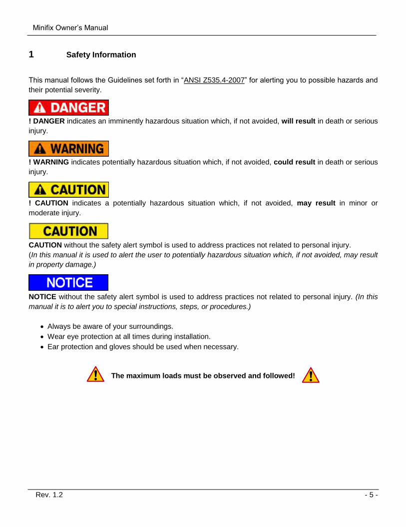
Safety Information 1
This manual follows the Guidelines set forth in “ANSI Z535.4-2007” for alerting you to possible hazards and
their potential severity.
! DANGER indicates an imminently hazardous situation which, if not avoided, will result in death or serious
injury.
! WARNING indicates potentially hazardous situation which, if not avoided, could result in death or serious
injury.
! CAUTION indicates a potentially hazardous situation which, if not avoided, may result in minor or
moderate injury.
CAUTION without the safety alert symbol is used to address practices not related to personal injury.
(In this manual it is used to alert the user to potentially hazardous situation which, if not avoided, may result
in property damage.)
NOTICE without the safety alert symbol is used to address practices not related to personal injury. (In this
manual it is to alert you to special instructions, steps, or procedures.)
Always be aware of your surroundings.
Wear eye protection at all times during installation.
Ear protection and gloves should be used when necessary.
The maximum loads must be observed and followed!
Minifix Owner’s Manual
Rev. 1.2 - 6 -
Important Notes 2
2.1 Attention
Before starting any operations of the liftgate, please read and understand this OWNER’S MANUAL. Its
intention is to act as a guide for the operation personal as well as to give help with preventive maintenance
but does not take place of unauthorized usage or repair by unqualified personnel.
Please contact your nearest PALFINGER Liftgates distributor or PALFINGER Liftgates in California or New
Jersey for assistance if you have questions regarding installation, operation or maintenance.
This owner’s manual applies to the following models: Minifix 500
This is the safety alert symbol. It is used to alert you to potential personal injury hazards. Obey all
safety messages that follow this symbol to avoid possible injury.
2.2 Important Notes
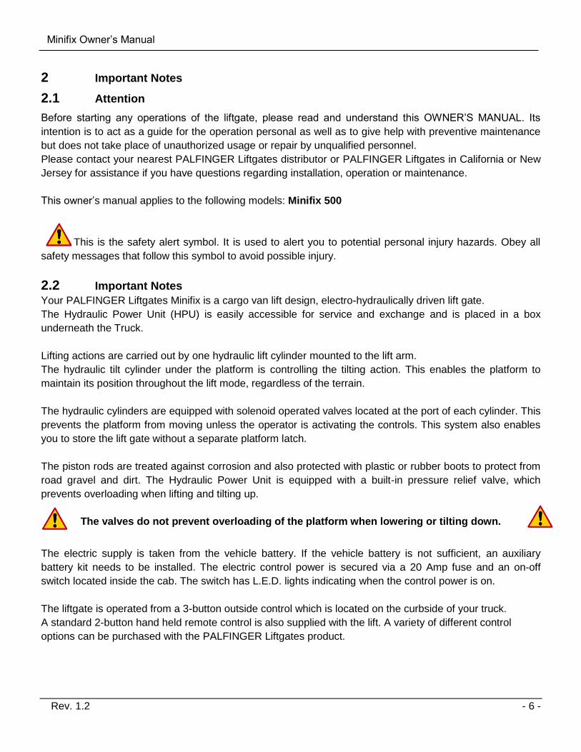
Your PALFINGER Liftgates Minifix is a cargo van lift design, electro-hydraulically driven lift gate.
The Hydraulic Power Unit (HPU) is easily accessible for service and exchange and is placed in a box
underneath the Truck.
Lifting actions are carried out by one hydraulic lift cylinder mounted to the lift arm.
The hydraulic tilt cylinder under the platform is controlling the tilting action. This enables the platform to
maintain its position throughout the lift mode, regardless of the terrain.
The hydraulic cylinders are equipped with solenoid operated valves located at the port of each cylinder. This
prevents the platform from moving unless the operator is activating the controls. This system also enables
you to store the lift gate without a separate platform latch.
The piston rods are treated against corrosion and also protected with plastic or rubber boots to protect from
road gravel and dirt. The Hydraulic Power Unit is equipped with a built-in pressure relief valve, which
prevents overloading when lifting and tilting up.
The valves do not prevent overloading of the platform when lowering or tilting down.
The electric supply is taken from the vehicle battery. If the vehicle battery is not sufficient, an auxiliary
battery kit needs to be installed. The electric control power is secured via a 20 Amp fuse and an on-off
switch located inside the cab. The switch has L.E.D. lights indicating when the control power is on.
The liftgate is operated from a 3-button outside control which is located on the curbside of your truck.
A standard 2-button hand held remote control is also supplied with the lift. A variety of different control
options can be purchased with the PALFINGER Liftgates product.
Minifix Owner’s Manual
Rev. 1.2 - 7 -
2.3 General Information
REMEMBER!
It is the fleet manager’s responsibility to educate the operator on the liftgate and its intended use. The
operator’s attention should be drawn to the permitted load limits and an understanding of the operation to
ensure the safety throughout the operation.
ONE-MAN OPERATION!
Never let an “outsider” operate the liftgate while you are handling the cargo.
A “misunderstanding” can result in serious personal injury.
In the interest of safety it is important that all operating personnel properly understand the functions
of the liftgate, possible hazards and dangers and the load limits and load positioning for that specific
unit.
IMPORTANT NOTICE!
Before the operator uses the liftgate, they should be thoroughly familiar with the lift’s functions and
usage according to the following:
1. Improper operation of this lift can result in serious personal injury. Do not operate unless you have
been properly instructed, have read and are familiar with the operation instructions. If you do not
have a copy of the instructions please obtain them from your employer, distributor or lessor, as
appropriate, before you attempt to operate the lift.
2. Be certain the vehicle is properly and securely stopped before using the lift.
3. Always inspect this lift for maintenance or damage before using it. If there are signs of improper
maintenance, damage to vital parts or slippery platform surface, do not use the lift. Do not attempt
your own repairs unless you are specifically trained.
4. Do not overload. See the Rating Label on the unit for the rated load. Remember that this limit
applies to both raising and lowering operations.
5. Each load should be placed in a stable position as near as possible to the body of the truck.
6. Never stand in, move through or allow anyone else to stand in or move through the area in which the
lift operates, including that area in which a load might fall.
7. This is not a passenger lift. Do not ride the lift with unstable loads or in such a manner that a failure
would endanger you. The lift is not equipped with a back-up system to prevent falling cargo in the
event of a failure.

Minifix Owner’s Manual
Rev. 1.2 - 8 -
2.4 Improper Useage
Some examples of improper use of the liftgate may include, but are not limited to:
Using the liftgate as an elevating work platform.
Using the liftgate to push, pull, or low load or other objects.
Using the liftgate to carry people (Only the operator may travel on the platform)
Using the liftgate to clear snow
Trying to use the liftgate as a “launching pad”
Using force of the hydraulic system to bend, shear, or break objects.
Driving a forklift over the liftgate.
Driving the vehicle with the platform open.
“Plowing” with the platform.

Minifix Owner’s Manual
Rev. 1.2 - 9 -
Important Information 3
Before Getting Started
“READ FIRST”
Before starting any operations of the liftgate, please read and understand this Owner’s Manual. The intention of this manual is to provide the user a guide for the operation as well as preventive maintenance. Do not attempt to modify or repair the liftgate unless performed by qualified personnel. Please contact your nearest PALFINGER Liftgates distributor or PALFINGER Liftgates in California or New Jersey for assistance if you have any questions regarding installation, operation or maintenance at 888-774-5844. This owner’s manual applies to the following models: Minifix 500 Important notes The electric supply is taken from the vehicle battery. If the vehicle battery is not sufficient, an auxiliary battery kit needs to be installed. The electric control power is secured via a 15-Amp fuse and an on-off switch located inside the cab. Trailer applications have an on/off switch near the rear curb side corner post. The liftgate is operated from a push buttons switch. A hand held remote control is standard with up and down functions. A variety of different control options can be purchased with the PALFINGER Liftgates product. The valves do not prevent overloading of the platform when lowering or tilting down.
Improper operation of this liftgate may result in severe personal injury or death. DO NOT operate unless you have been properly instructed, have read and are familiar with the procedures in this manual. This manual has been designed to illustrate the steps needed for the basic operation of the ILT liftgate. It also provides safety information and simple preventive maintenance tips.
This manual is not intended for use as a repair or troubleshooting guide. Repairs should be performed by a PALFINGER Liftgates Authorized Service Center.
Minifix Owner’s Manual
Rev. 1.2 - 10 -
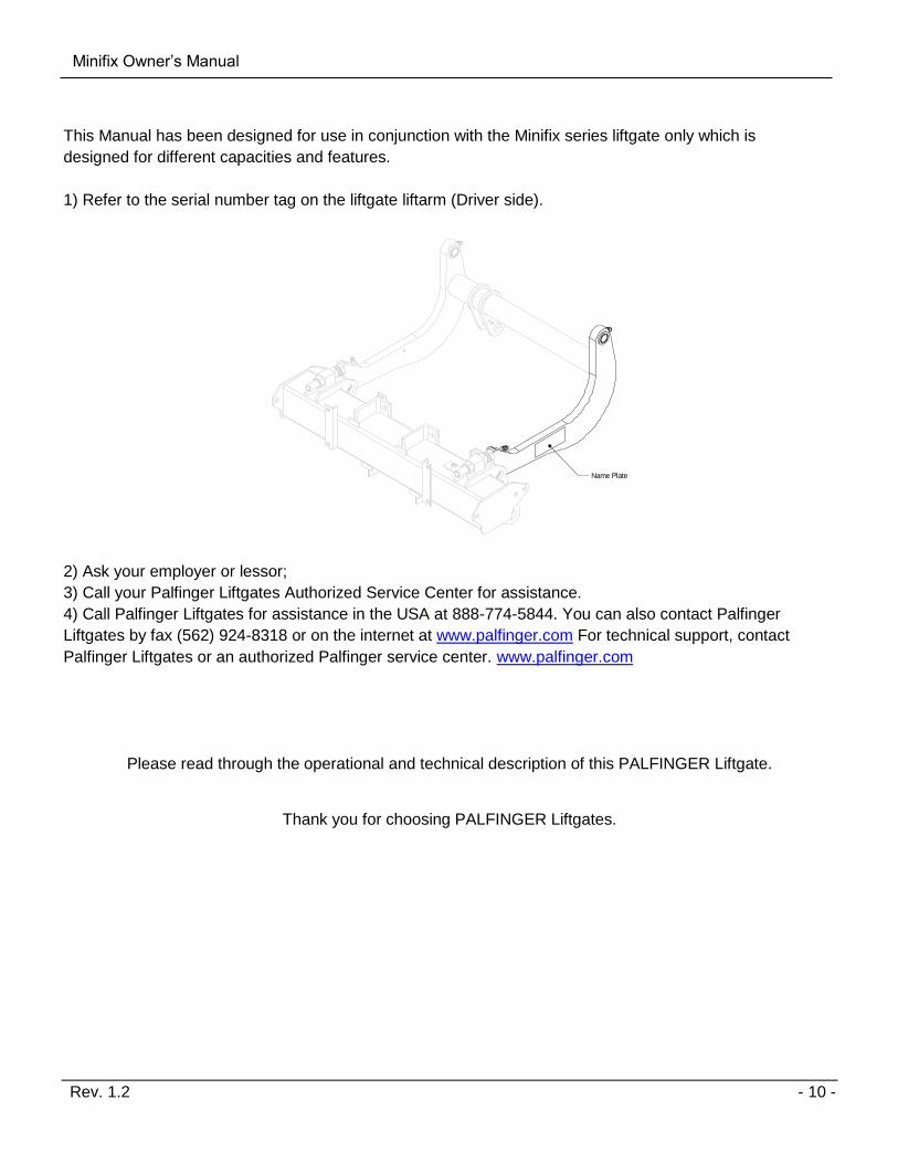
This Manual has been designed for use in conjunction with the Minifix series liftgate only which is
designed for different capacities and features.
1) Refer to the serial number tag on the liftgate liftarm (Driver side).
Name Plate
2) Ask your employer or lessor;
3) Call your Palfinger Liftgates Authorized Service Center for assistance.
4) Call Palfinger Liftgates for assistance in the USA at 888-774-5844. You can also contact Palfinger
Liftgates by fax (562) 924-8318 or on the internet at www.palfinger.com For technical support, contact
Palfinger Liftgates or an authorized Palfinger service center. www.palfinger.com
Please read through the operational and technical description of this PALFINGER Liftgate.
Thank you for choosing PALFINGER Liftgates.

Minifix Owner’s Manual
Rev. 1.2 - 11 -
General View of Liftgate 4
Platform
Liftarm
Power Pack(Pump and MotorEnclosure)
Mount Tube
Tilt Cylinder(Under Platform)
ParallelArm
Foot Control(Optional)
Warning Lights(Optional)
Pump and Motor Enclosure
LiftCylinder
ControlBoard
Pump & Motor
Oil Resevoir
CartStops

Minifix Owner’s Manual
Rev. 1.2 - 12 -
Maximum Load and Placing of Load of Platform: 5
All liftgates are rated up to a maximum load. The point of maximum load is rated at a defined distance. The center point of maximum load is at 24” from start of vehicle body, as shown below.
18 24 30 36 42 48 54 60 66 72 78 84 9010
20
30
40
50
60
70
80
90
100
Distance From Body (inches)
Capaci
ty (
%)
Load
24"
Capacity
100% at 24"80% at 30"45% at 48"25% at 60"
By increasing this distance the maximum load of the liftgate is decreasing. The maximum loads must be observed and followed.

Minifix Owner’s Manual
Rev. 1.2 - 13 -
Operating Liftgate 6
Always observe the platforms operating range when opening. Do not stand in the platforms
swiveling range as it can lead to serious injuries.
Operating instructions below are described for Horizontal mounted buttons. If buttons have been
installed vertically, follow the Vertical Mounted button operations.
6.1.1 Operation by Push Buttons
1. Turn the Control Switch “ON” from inside the cab. LED lights on the switch should be lit up when the liftgate is ready to use and off when the liftgate is unoperational.
LED Lights
2. From stored position, press and hold the TOP button until the platform is in horizontal position.
Top Button
Horizontal Buttons Vertical Buttons
Top Button

Minifix Owner’s Manual
Rev. 1.2 - 14 -
3. To lower the platform, press and hold the BOTTOM button. Keep pressing the BOTTOM button to have the platform tilt down.
Bottom Button
Horizontal Buttons Vertical Buttons
Bottom Button
4. The platform is ready to load. Center the load at 24” from the end of the vehicle body. Press and hold the RIGHT and BOTTOM buttons simultaneously to the raise platform to a horizontal position. Maintain the buttons pressed to raise the load to vehicle bed level.
Bottom Button
Right Button
Horizontal Buttons Vertical Buttons
Middle Button
Bottom Button
5. To store platform, press and hold the TOP and RIGHT buttons simultaneously to raise the platform to bed level. Maintain the buttons pressed to raise the platform vertically against the rubber stop.
Top Button Right Button
Horizontal Buttons Vertical Buttons
Middle Button
Top Button

Minifix Owner’s Manual
Rev. 1.2 - 15 -
6.1.2 Operation by Hand Held Remote Control
The Hand Held Remote Control allows you to lower the gate down and lift it up. It has no tilting function.
1. Lifting Up: Push button number 1 2. Lowering Down: Push button number 2
6.1.3 Operation by Foot Control
DOWN:
Step on the front and hold – wait between one and
three seconds before you step on the rear switch.
For auto tilt, stay on the switches till platform starts tilting.
UP:
Step on the rear switch and hold – wait between one and
three seconds before you step on the front switch
The platform will tilt up to preset position before rising.
IF BOTH SWITCHES ARE NOT ACTIVATED
WITHIN THREE SECONDS, START OVER.
Lift DOWN
Lift UP
Tilt DOWN (at ground level)
Tilt UP (at ground level)White Button
Black Button
Front Switch
Rear Switch
Stre
et S
ide
Curb
Sid
e

Minifix Owner’s Manual
Rev. 1.2 - 16 -
6.1.4 Operation by Push Wireless Hand Held Remote
1. Power the remote by using the ON/OF switch on the rear of the control. 2. Each function has a separate button. Functions are displaced as below 3. After finishing using the gate, switch the power off on the remote.
Tilt Up
Tilt platform up
Tilt Down
Tilt platform down
Down
Lower platform
Up
Raise platform

Minifix Owner’s Manual
Rev. 1.2 - 17 -
Cart Stops 7
For the transportation of rolling containers without brakes, the platform is equipped with cart stops (roll stops).
The cart stops have a lid, which opens by operating the lever by foot. This lid fits for rolling containers with
maximum roller diameter of 7” when the platform is positioned horizontally.
Press down on leverto spring up cart stop
Cart StopSprung Open
To close after usestep on lid
Lid

Minifix Owner’s Manual
Rev. 1.2 - 18 -
Preventive Maintenance and Quick Check 8
The Minifix needs preventive maintenance to perform at its fullest capacity. Lubricate and inspect regularly.
Also check that all details are damaged: Hoses, cables, controls, etc.
REPAIR OR REPLACE IMMEDIATELY FAULTY PARTS
8.1 Maintenance and Care
The following “inspection and maintenance” should be performed at the recommended intervals depending
on operation and amount of cycles or at the time when the unit shows any signs of damage or abuse.
Remember that the secret to a long life of your PALFINGER Liftgate is to maintain it through preventive
care.
* Recommended bases for
inspection and maintenance
Depending
on use Daily Monthly Quarterly
cleaning x
general lubrication of pins and
bushings x
oil level inspection x
oil change x
check hydraulic hoses and pipes for
leaks x
check controls and connections x
check pins and pin retaining bolts x
check batteries and connections x
check warning labels and other safety
equipment for effectiveness and
visibility
x
visual check for loose or missing parts
and un-usual noise during operation x
check lock bolts and pins for tightness x
check complete function of gate x
check mounting brackets of lift gate to
frame for cracks or damage visually x
All parts except the chrome-coated piston rods, the push buttons, solenoids valves, foot controls
and warning lights can be cleaned by means of a water jet.

Minifix Owner’s Manual
Rev. 1.2 - 19 -
8.2 Lubrication
Properly lubricated, the PALFINGER Liftgates Minifix liftgate will ensure longevity. Therefore, lubricate the
lift at the same time as the truck. Grease more frequently if the liftgate is heavily used. The liftgate should
be greased every 1200 cycles (depending on use – estimated every 3 month).
8.2.1 Lubrication Plan
All bearing points must be lubricated in accordance with the maintenance intervals.
1. Lower the platform to the ground.
2. Remove red protector caps from each component. Lubricate, grease, and oil as shown below.
3. Cycle platform up and down several times. Lubricate and grease all points again.
4. Wipe any excess grease and replace all red protector caps on zerks.
2 zerks:- 1 Liftarm- 1 Parallel arm
4 zerks:- 1 Liftarm- 1 Parallel arm- 2 Shackle- 1 Tilt Cylinder
IN
Cart Stops
Check and refill oil.
IN
OUT
2 zerks:- 1 Cylinder- 1 Liftarm
2 zerks:- 1 Cylinder- 1 Liftarm
Grease: Location of Grease Zerks
IN
OUT Oil: Oil Level in the power pack tank
IN Lubrication: Cart Stops (use WD-40 spray for lubrication).
Minifix Owner’s Manual
Rev. 1.2 - 20 -
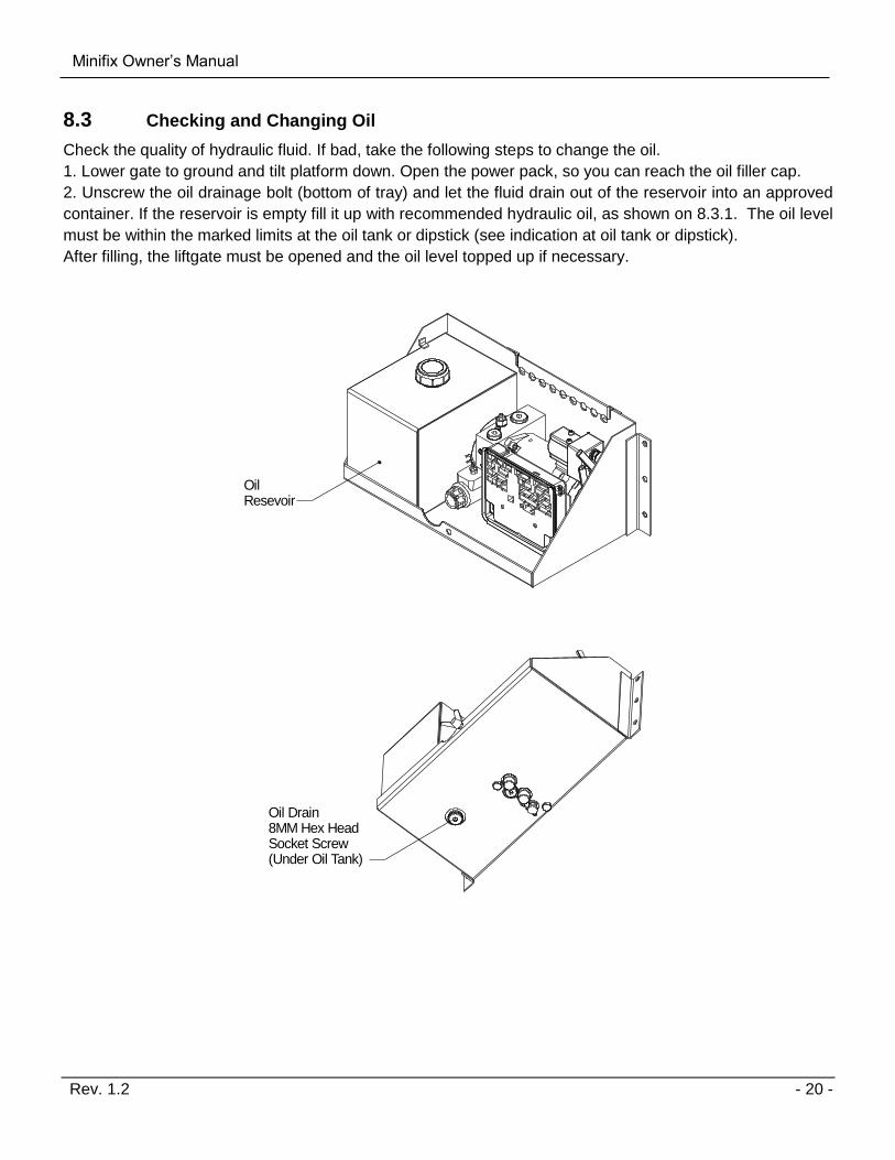
8.3 Checking and Changing Oil
Check the quality of hydraulic fluid. If bad, take the following steps to change the oil.
1. Lower gate to ground and tilt platform down. Open the power pack, so you can reach the oil filler cap.
2. Unscrew the oil drainage bolt (bottom of tray) and let the fluid drain out of the reservoir into an approved
container. If the reservoir is empty fill it up with recommended hydraulic oil, as shown on 8.3.1. The oil level
must be within the marked limits at the oil tank or dipstick (see indication at oil tank or dipstick).
After filling, the liftgate must be opened and the oil level topped up if necessary.
Oil Resevoir
Oil Drain8MM Hex Head Socket Screw(Under Oil Tank)

Minifix Owner’s Manual
Rev. 1.2 - 21 -
8.3.1 Recommended Hydraulic Fluids
TEMP. RANGE BRAND
-10 TO 150 F EXXON UNIVIS J26
MOBIL OIL DTE 13M
CHEVRON AW MV32
ROSEMEAD MV 150 (32)
-50 TO 150 F MOBIL DTE 13M
SHELL AERO FLUID 4
EXTREME COLD TEMPERATURE: USE MILITARY SPEC: MIL H5606

Minifix Owner’s Manual
Rev. 1.2 - 22 -
8.4 Quick Check List
1. Operate the lift gate throughout its entire operation and check for noise and damage such as bent parts or cracked welds.
2. Inspect all welds and fasteners that attach the mount frame to the truck. All pins and bolts that connect the lift arm to the mount frame and to the platform.
3. Visually inspect the hydraulic lines for damage, scratches, bending or leakage.
4. Inspect the cylinders for leakage and that the cylinder pins are secured with lock bolts.
5. Check the oil level when the platform is down at ground level. The level should fall between the markings on the tank. We recommend replacing oil after the first 1200 cycles, after that on a yearly basis in the fall before winter begins.
6. Check for oil leakage around the power pack and inside mount tube. Tighten or replace components if needed. If you perform work on any hydraulic components bleed the air out of the system by operating all functions several times.
7. Check all electrical connections. Clean and protect battery terminals and check for tightness.
8. Inspect all the terminals on the solenoid-operated valves at the port of the cylinder. Lubricate the terminals for better protection from oxidation if needed.
9. Grease all zerks on the lift gate and make sure they all take grease. Sometimes it helps to operate the lift gate while you do this.
10. Test all the lift gate functions, if possible with maximum loads placed according to load diagrams.
11. Check the function of the pressure relief valve.
12. When doing daily checks and you find any kind of damage that can make the use of the liftgate dangerous, it must be repaired before using. All repairs should be made by an authorized technician. Use only original spare parts. If in doubt contact your PALFINGER Liftgates distributor or call PALFINGER Liftgates directly.
Do not cover up any accidents or damage; it can be dangerous for you and your co-
workers.
Minifix Owner’s Manual
Rev. 1.2 - 23 -
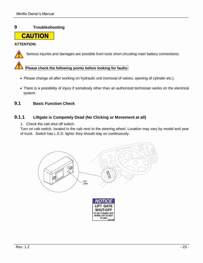
Troubleshooting 9
ATTENTION:
Serious injuries and damages are possible from tools short circuiting main battery connections.
Please check the following points before looking for faults:
Please change oil after working on hydraulic unit (removal of valves, opening of cylinder etc.).
There is a possibility of injury if somebody other than an authorized technician works on the electrical
system.
9.1 Basic Function Check
9.1.1 Liftgate is Competely Dead (No Clicking or Movement at all)
1. Check the cab shut off switch.
Turn on cab switch, located in the cab next to the steering wheel. Location may vary by model and year
of truck. Switch has L.E.D. lights: they should stay on continuously.
LED Lights

Minifix Owner’s Manual
Rev. 1.2 - 24 -
2. Check the circuit breaker at the main batteries.
Every vehicle has a circuit breaker on top of the main battery.
If circuit breaker reset arm is popped out, push it back in as shown on the decal ATG-BKR next to your
breaker or on battery box lid.
Circuit Breaker Location
Buss Bar
Battery Mount Resettable Circuit Breaker Reset Required when Tab is Exposed
3. Are the vehicle batteries charged?
Check batteries and the truck charging system. Start truck and run engine in fast idle for charging the
batteries. If liftgate starts working, recharge batteries.
4. Check the fuses in the power pack.
In the Hydraulic Power Unit next to the motor you will find 2 fuses. Check for burned fuse and
replace it with the same type.
Fuse Holderson ControlBoard Replace when
metal bridge isbroken
In-Line ATC Fuse 15 Amp at Control Board. Replace with same amperage fuse when necessary. In-Line ATC Fuse: 20 Amp at Battery. Replace with same amperage fuse when necessary. NOTICE: DO NOT attempt to jump in-line fuses with other objects other than the specified fuse(s). DO NOT increase the amperage rating of fuse. Serious harm to the liftgate will result when standard practices are not followed.
Minifix Owner’s Manual
Rev. 1.2 - 25 -
5. Is the connection to ground in power pack OK?
Is the ground connection from the liftgate to vehicle OK?
6. Check the oil level in the power pack reservoir.
7. Are there any damages on mechanical or electrical parts (such as damaged cables)?
9.1.2 On-Off L.E.D.s are on but all functions are dead
Possible malfunctions:
1. Short in hand held remote or its wire remove plug J-31.
2. Short in push button switches wire remove plug J-30.
After disconnecting plugs – reboot board by unplugging J-1 for 5 seconds and plug it back.
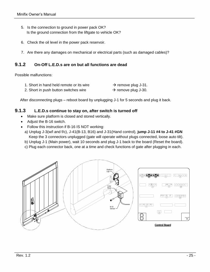
9.1.3 L.E.D.s continue to stay on, after switch is turned off
Make sure platform is closed and stored vertically.
Adjust the B-16 switch.
Follow this instruction if B-16 IS NOT working:
a) Unplug J-3(w/l and f/c), J-41(B-13, B16) and J-31(Hand control), jump J-11 #4 to J-41 #GN
Keep the 3 connectors unplugged (gate will operate without plugs connected, loose auto tilt).
b) Unplug J-1 (Main power), wait 10 seconds and plug J-1 back to the board (Reset the board).
c) Plug each connector back, one at a time and check functions of gate after plugging in each.
Power LED
PlatformClip
B-16 Sensor
ColorResin
Control Board

Minifix Owner’s Manual
Rev. 1.2 - 26 -
9.1.4 Platform tilts down before it reaches the ground
Adjust B-13 lift arm switch.
B-13 is not working unplug J-41 (gate operates without sensor but loses auto-tilt).
Power LED
Lift Arm (Curb Side)
B-13 Sensor
Lock Tab
Resin
8"-10"
Control Board

Minifix Owner’s Manual
Rev. 1.2 - 27 -
9.2 Possible Cause & Remedy of Liftgate Malfunction
FAULT POSSIBLE CAUSE REMEDY
Red warning lights do not flash when
starting up
1. Control Device is defective
2. PC-Board is defective
1. Replace
2. Replace
Warning lights do not flash when
platform opens (if equipped)
1. Tilt angle of sensor B16 is
defective
2. PC-Board is defective
3. Motor is defective
1. Replace
2. Replace
3. Replace
Power Pack does not run when
opening function activated
1. Push button does not give any
contact
2. Motor contactor is defective
3. Motor is defective
1. Replace
2. Replace
3. Replace
Motor starts up but platform does not
open
1. Solenoid valve S3 on
Tilting Cylinder does not open
2. Control Valve S5 or Shuttle
Valve jams
1. Clean or Replace
2. Clean or Replace
Platform opens too slowly or does not
open to horizontal position
1. Flow control valve R4 jam
or defective
2. Electric motor malfunctioning
3. Control valve S5 or shuttle
valve jams or defective
4. Hydraulic oil too thick
5. Bearings mechanical jamming
1. Clean or Replace
2. Check Collector and replace
carbon brushes if necessary
3. Clean or Replace
4. Change oil as recommended
5. Lubricate bearing points
Platform tilts during lowering
operation (before reaching the
ground)
1. Tilt angle of B13 Sensor is
incorrectly adjusted
1. To set the time of tilting, tilt the
angle on B13 counter-clockwise to
start the tilting procedure later.
Platform tilts on its own 1. Solenoid valve S3 on
tilting Cylinder soiled or
defective
2. Piston seal in tilting Cylinder is
defective
1. Clean or Replace
2. Replace
Platform lowers on its own 1. Solenoid valve S1 on
lifting Cylinder soiled or
defective
1. Clean or Replace

Minifix Owner’s Manual
Rev. 1.2 - 28 -
Platform does not tilt or very
unsteadily after reaching the ground
1. Flow valve R5 or shuttle valve
jam or defective
2. Tilt angle switch B13 is adjusted
incorrect or defective
3. PC-Board is defective
4. Solenoid valve S3 on
tilting Cylinder soiled or
defective
1. Adjust or Replace
2. B13 Sensor is defective or its
tilt angle is incorrectly set
3. Replace
4. Clean or Replace
Platform does not tilt or lift at lifting
mode
1. Operating buttons or switches,
foot or remote control is
defective
1. Replace defective Parts
Platform lifts but does not tilt at lifting
mode
1. Directional valve S5 jams or is
defective
2. Tilt angle Sensor B16 is
defective
1. Clean or defective
2. Replace
Platform tips further in lifting mode
that preset
1. Tilt angle sensor B16 is
defective
2. Directional valve S5 jams or
defective
1. Replace
2. Clean or Replace
Platform does not lift, even the
hydraulic unit is running
1. Directional valve S5 jams or is
defective
2. Solenoid valve S1 on
lifting Cylinder is soiled or
defective
3. Suction Filter on pump soiled
4. Platform overloaded
5. Hydraulic pump is defective
6. Electrical motor is defective
7. Shuttle valve soiled or defective
8. Pressure control valve
incorrectly set or defective
1. Clean or Replace
2. Clean or Replace
3. Clean or Replace
4. Reduce load in accordance with
the load table
5. Replace pump
6. Replace motor
7. Clean or Replace
8. Reset and lead or Replace
Platform does not close 1. Directional valve S5 jams or
defective
1. Replace defective Parts

Minifix Owner’s Manual
Rev. 1.2 - 29 -
9.3 Electrical and Hydraulic Schematic
9.3.1 Battery Wiring Diagram
2GA. LiftgatePower Cable
4-Conductor Power Cablefrom Control Board
VehicleBattery
*In-Line Fuse
Wires #1 and Gr/Ylgo to ground (-)
**Resettable CircuitBreaker
Wires #2 and #4go to postitive (+)
AuxiliaryBattery
2GA. LiftgateGround Cable
**Resettable CircuitBreaker
*In-Line ATC Fuse: 20 Amp. Replace with same amperage fuse when necessary. **Resettable Circuit Breaker: 150 Amp Min. Replace with same amperage breaker when necessary. ***Ground: For optimal grounding, ground all batteries and power units to the body side rails of the vehicle. NOTICE: DO NOT attempt to jump in-line fuses with other objects other than the specified fuse. Do not increase the amperage rating of fuse. Serious harm to the liftgate will result when standard practices are not followed.

Minifix Owner’s Manual
Rev. 1.2 - 30 -
9.3.2 Electrical Schematic
Circu
it D
iagra
m12V
Min
ifix
Tilt
Lift
Lift
Tilt
Cab C
ut O
ffB
-13B
-16
Warn
ing L
ights
Foot C
ontr
ol
Batt.
J-1 2+27, 12V
J2 G
round
Pum
p a
nd M
oto
r
Hand C
ontr
ol
20A
15A
x2
4A
45
67

Minifix Owner’s Manual
Rev. 1.2 - 31 -
9.3.3 Connector Overview
B13 LIFT ARM FOOT CONTROL
WARNING LIGHTS
CAB CUT OFF SWITCH
POWER PACK
GROUND for PC BOARD(green/yellow and black # 1)
POSITIVE for PC BOARD(black #2 to 2 and black # 4 to 27)
CYLINDERSLIFT 15 (2 ea)TILT 14 (2 ea)
BL - BlueBR - BrownSW - BlackGE - YellowGN - Green- Negative+ Positive
AUX Port
Power LED
B15 PLATFORM
Control Board Codes:
System ok / Cab switch off, (or missing bridge J11/2<->4)
System ok / Cab switch on, (or bridge J11/2<->4)
Low Voltage
Missing tilt switch B-13 at lift arm or defective.
Missing tilt angle sensor B-15 at lift platform or defective
Missing tilt angle sensor B-15 at platform or defective
Warning lights shorted
Short in cab switch/on-off switch or aux port
General short in electrical wiring
Emergency program (all sensors are bypassed).Activation by: Press Open+Lower>10 seconds
Diagnosis mode activated
Defect at motor solenoid detected during lifting
Voltage V02 (J1 pin 2) is missing, defective fuse
Defect at opening, valve (S3/S4) or motor relay detected during opening
S5 valve detected during closing or motor solenoid defective
S5 valve detected or defect at lowering valve (S1/S2)
Cab switch: off/on (or disconnect bridge J11/2<->4)
Automatically when the valves are back to normal
Automatically when the valves are back to normal
Automatically when the valves are back to normal
Cab switch: off/on (or disconnect bridge J11/2<->4) or closetail lift
Cab switch: off/on (or disconnect bridge J11/2<->4) or closetail lift
Cab switch: off/on (or disconnect bridge J11/2<->4) orvoltage interruption MBB control
Cab switch: off/on (or disconnect bridge J11/2<->4)
Automatically when the valves are back to normal
Replace the fuse
Automatically when the valves are back to normal
Automatically when the valves are back to normal
Automatically when the valves are back to normal
Removing service connector
Code Description Reset
HAND REMOTE

Minifix Owner’s Manual
Rev. 1.2 - 32 -
Functions:
Lift: MLower: S1+ S5Tilt Up: M+S5Tilt Down: S2Horiz. Open: M+S2
Pressure Relief
2850 PSI200 bar
Shift Valve S5
Restrictor Valve R5
Flow Divider
Functions:
S1 = Release Valve for lowering functionS2 = Release Valve for tilt down functionR1 = Flow Restrictor located inside hose adaptor on lift cylinderR2 = Flow Restrictor located inside hose adaptor on tilt cylinderS5 = Shift Valve is activated on tilt up and lowering functionR5 = Restrictor Valve located in power packFlow Divider is activated, when fluid is going back into the power packIf Flow Divider is loose or hanging up the fluid is circulated back in to tank
2
2
Datum
01.08.08
Hydraulic Schematic
HACKBARTH
Minifix
9.3.4 Hydrualic Schematic

Minifix Owner’s Manual
Rev. 1.2 - 33 -
Decal Placement 10
For operator’s safety, all decals appearing in “Decal Kit” must be in a conspicuous place on control side of
liftgate to be read by operator. This is typically a combination of decals on the liftgate and truck body.
Please make sure to place the maximum capacity decal (C) on driver and curb side.
IMPORTANT: Never remove or paint over any decal.
Decal Kit
Decal Qty. Part No. Description
A 1 ATG-URGWA Urgent Warning: Elevating gate instructions
B 1 85-0915-000
85-0915-001
Operating Instructions (Horizontal Buttons)
Operating Instructions (Vertical Buttons)
C 2 ATG-XXXX Capacity (Liftgate capacity can be found on serial
number plate located on the liftarm)
D 1 ATG-CAB Liftgate Shut-Off (located next to shut-off switch in cab)
E 1 ATG-BKR Max. Circuit Breaker Reset (must be located at the
circuit breaker)
F 2 ATG-WLH Warning: liftgate can crush
G 2 ATG-PLAT Warning: Always stand clear of platform area
H 1 ATG-RESET Circuit Breaker Protection
I 1 ATG-FT Notice for Foot Control (if applicable)

Minifix Owner’s Manual
Rev. 1.2 - 34 -
C
Rear of Vehicle Curb Side of VehicleDriver Side of Vehicle
C
B
A
E
F
H
G G
Decal - A
Decal - B
Decal - D Decal - F
Decal - B
Decal - C
Decal - E Decal - G
Decal - H Decal - I
Minifix Owner’s Manual
Rev. 1.2 - 35 -
Required Information for Ordering Spare Parts and Repairs 11
11.1 Ordering Spare Parts
In order to assure quick delivery of spare parts, please always state the following information when making
orders:
1. Liftgate model & serial number.
2. Designation and number of the spare part in accordance with the spare parts list.
3. Designation and number marked on the individual component (if available).
11.2 Repairs
Parts sent to Palifinger Liftgates to repair must be accompanied by a letter (in separate cover) giving details
and scope of the repairs required.

Minifix Owner’s Manual
Rev. 1.2 - 36 -
Warranty 12
PALFINGER Liftgates provides warranty as part of its conditions of delivery.
Spare part deliveries are all billed. Palifinger Liftgates then issues credit for all or part of the invoiced sum,
when Palifinger Liftgates has been able to determine that the warranty claim is justified as defined by its
warranty conditions. Palifinger Liftgates does this by inspecting the defected parts which are sent back to
Palifinger Liftgates freight-prepaid as well as the written description of the problem which must have been
filled out in full.
The parts that are sent back to Palifinger Liftgates, marked with serial number and address, become
Palifinger Liftgates’ property if the warranty claim is accepted.
All warranty claims must be received within 30 days of repair or replacement. Including the following
information:
1. Liftgate model.
2. Liftgate serial number.
3. Description of problem.
4. Itemized bill of repair with breakdown of number of hours to perform warranty work and labor changes
per repair.
5. Parts used for repair with Palifinger Liftgates part number.
6. RMA#.
7. Contact at Palifinger Liftgates, if applicable.
Model Pump and Motor Cylinders Hardware Control System Hydraulic
Minifix 2 yr 3 yr 3 yr 2 yr 2 yr
Table Warranty Coverage Schedule
Effective: Aug. 2010

Minifix Owner’s Manual
Rev. 1.2 - 37 -
Contact Address 13
15939 Piuma Ave Cerritos, CA 90703
Phone: (562)-924-8218 Fax: (562)-924-8318
E-mail (parts order):
E-mail (technical support): [email protected]
572 Whitehead Road Trenton, NJ 08619
Phone: (609)-587-4200 Fax: (609)-587-4201
E-mail (parts order):
E-mail (technical support): [email protected]