Owner s Manual - Öhlins1 Owner's Manual Öhlins motocross front forks 48 MXF 2007 Including:...
20
Owner ' s Manual Öhlins motocross front forks 48 MXF 2007 Including: Setting up your bike Fine-tuning Service the fork Technical info Spare parts General handling set-up
Transcript of Owner s Manual - Öhlins1 Owner's Manual Öhlins motocross front forks 48 MXF 2007 Including:...

1
Owner's ManualÖhlins motocross front forks 48 MXF 2007
Including:
Setting upyour bike
Fine-tuning
Servicethe fork
Technical info
Spare parts
Generalhandling set-up

2
Safety signalsImportant information concerning safety isdistinguished in this manual by thefollowing notations:
The Safety alert symbol means:Caution! Your safety is involved.
WARNING!Failure to follow warning instructionscould result in severe or fatal injuryto anyone working with, inspecting orusing the suspension, or to bystanders.
CAUTION!Caution indicates that special pre-cautions must be taken to avoid dam-age to the suspension.
NOTE!This indicates information that is ofimportance with regard to procedures.
IntroductionAll of Öhlins advanced suspension products areadapted to the brand and model. This means thatlength, travel springaction and damping charac-teristics, are tested individually just for themotorcycle that you have decided to fit withÖhlins suspension.
Before installationÖhlins Racing AB can not be held responsible forany damage whatsoever to front fork or vehicle,or injury to persons, if the instructions for fittingand maintenance are not followed exactly.
Similarly, the warranty will become null and voidif the instructions are not adhered to.
© Öhlins Racing AB.All rights reserved.
Any reprinting or unauthorized usewithout the written permission ofÖhlins Racing AB is prohibited.
Printed in Sweden.
WARNING!1. Installing a front fork, that is not approved bythe vehicle manufacturer, may affect the stabilityof your vehicle. Öhlins Racing AB cannot be heldresponsible for any personal injury or damagewhatsoever that may occur after fitting the frontfork.
2. Please study and make certain that you fullyunderstand all the mounting instructions andthe owners manuals before handling this frontfork kit. If you have any questions regardingproper installation procedures, contact anÖhlins dealer.
3. The vehicle service manual must be referredto when installing the Öhlins front fork.
NOTEÖhlins products are subject to continual improve-ment and development. Consequently, althoughthese instructions include the most up-to-dateinformation available at the time of printing, theremay be minor differences between your suspen-sion and this manual. Please consult your Öhlinsdealer if you have any questions with regard tothe contents of the manual.
ContentsSafety signals ................................................ 2Introduction ................................................... 2Before installation .......................................... 2Tuning the suspension ................................... 3Design ........................................................... 3Settings ......................................................... 4Setting the spring preload ............................. 4Fine-tuning the bike ....................................... 5Changing springs .......................................... 7Dismantling ................................................... 9Asembling ................................................... 12Technical specifications ............................... 14Spare parts .................................................. 15General handling set-up .............................. 18Maintenance ................................................ 19

3
Tuning the suspension
Motorcycle road holding qualitiesAll motorcycles are designed with a suspensiongeometry that includes height and fork angle. Thechanging of components can affect this and it istherefore essential that both the rear and the frontends match each other.
Changing to Öhlins suspension gives optimumperformance only when both the front fork andthe rear suspension interact properly. It is of thegreatest importance that the front and rear loadedheights are within the specified values.
In the Mounting Instructions, see section:Setting the spring pre-load.
DesignÖhlins upside-down (USD) front fork isdesigned to combine the advantages of comfort-able, safe conventional forks and rigid, light USDforks. The result is a unique combination of beingrigid, precise in corners and during hard braking
Spring pre-load is adjusted with a nut (key width17 mm) (Fig.3) and optional springs are availableto suit different tracks and riders.In the legs there are also “air-springs“ (the air
trapped above the oil) that work together withthe “real“ spring. You adjust the air-spring byraising or lowering the oil level in the legs.By using different combinations of springs and
air-springs you can alter the characteristic of thefork. For example, a soft spring in combinationwith a small air-spring (high oil level) makes thefork more progressive; see Fine-tuning the bike.
MarkingAll Öhlins front forks are marked. You will find thepart number on the inside of the fork bottom.
Recommended settingsThe front fork in your kit is adjusted to the Öhlinsrecommended setting for your bike (see Moun-ting Instructions). We advise you to use this asyour start setting.
yet comfortable, forgiving during “over-landing“and in big bumps.Your Öhlins USD front fork has aluminium outer
legs and 48 mm steel inner legs, with a polishedsurface for lowest possible friction.The USD front fork features the Öhlins cartridge
damping system equipped with a free pistonpositioned on the outside of the cartridge. Thiswill prevent cavitation and keeps the dampingforces effective even in extreme riding conditions.The fork is fully adjustable with external adjuster
for compression and rebound damping.The compression adjuster is located at the bot-
tom of the fork leg (Fig.1), the rebound adjusterat the top (Fig.2).
NOTE!Turning clockwise will increase the damping forces– turning counterclockwise will reduce the damp-ing forces. Similar procedures for spring pre-load.
1.The compression adjuster is located at thebottom of the fork leg. Adjustments are madeby turning the screw. Use a slot screw driver.
2.The rebound adjusteris located at the top ofthe fork leg.
3.Spring preload isadjusted with a nutand optional springsare available.

4
Settings
Basic settingsAlways ensure that the basic setting made byÖhlins is correct. It is adapted to the make andmodel (in its original state) and for a rider ofaverage weight.
WARNINGIncorrect spring action can produce a fork anglethat is too steep or too flat. This in turn will give atendency for oversteering or understeering, whichcould seriously affect the handling characteristicsof the motorcycle.
RecommendationsThe difference should not deviate from thefollowing sizes, if no other recommended settingsare given in the Mounting Instructions:
Free sag: (R1-R2), (F1-F2)Rear: MX/Enduro 30±5 mmFront: MX/Enduro 30±5 mm
Ride height: (R1-R3), (F1-F3)Rear: MX 100±5 mm
Enduro 30% of the total strokeFront: MX/Enduro 80±5 mm
Setting the spring pre-load
MeasuringPreload on the spring/springs is very important,because it affects the height of the motorcycle andthe fork angle. Consequently, handling characteristicscan be changed, even negatively. Proceed as follows(it will be much easier if done by two persons):
• Place the motorcycle on a stand, so thefront fork and the rear end are in fullyextended position.
• Measure the distance, e.g. from thelower edge of the rear mudguard orfrom a point marked by a piece of tape,immediately above the rear wheel axle,to the wheel axle (R1).
• Make a similar measurement on the front axle,e.g. from the bottom of the upper fork crownto the front wheel axle (F1).
• Allow the motorcycle (without rider) toapply load on the springs and repeat themeasuring procedure (R2, F2).
• Then take the same measurements withthe rider and equipment on themotorcycle (R3, F3). It is important that the riderhas a correct riding posture, so that theweight is balanced on the front and rearwheel in the same way as when riding.
Bike on a stand.
F1
R1
Bike on the ground.
F2
R2
Bike with rider on.
F3
R3
NOTE!See Mounting Instructions for recommendedsettings.
The original setting of the front fork, when deliveredfrom Öhlins, should always be a base when the set-tings are changed by use of the adjustment devices.

5
Setting the damping forcesLearning how to use the adjusters will take timebut you will quickly appreciate them once youknow the tricks. Even the specialists sometimesneed a specialist!With the adjusters you optimize the suspension
for your riding style and the track you are com-peting on.The same basic guidelines go for both the front
fork and the rear shock absorber.Too much compression damping will give you a
harsh ride as your bike “jumps“ along the track.With too much rebound damping your bike will
have difficulties with several bumps in a row. Thesuspension will not extend fast enough betweenbumps, your bike will ride lower and lower andeventually the suspension will bottom!
External adjustersThe front fork is equipped with a base valve anda mid-way bleed valve, controlling the flow dur-ing the compression and rebound stroke.
CAUTION!Using too much force when closing the adjust-ers will destroy important sealing surfaces.
Compression stroke Rebound stroke
Flow in thebase valve
Flow in themid-way valve Flow in the base valve Flow in the mid-way valve
All of the adjusters have a normal right-hand thread.Click position zero (0) is when the adjusters are
turned clockwise to fully closed.The adjustment range, from fully closed until
maximum open valve (counter clockwise), is 20clicks.In order not to click in the wrong direction; always
first close the adjuster, then dial-in the new setting.
Making adjustmentsTo make improvements using the adjusters, it isimportant to understand the function of the frontfork and the shock absorber and through testinglearn how they effect the handling of your bike.Make sure that you have the correct springs
and the correct spring preload before makingany adjustments. And always start with theÖhlins recommended settings.
NOTE!Higher click numbers give less damping force.
When making adjustments, keep notes, makeadjustments one at a time…and in small steps.The adjusters should normally not be adjusted
in steps of more than 2 clicks at a time and notoutside the usable click range.
Function of the PS (Pressurized system)The base valve (1) and the free piston (2) act to-gether in the compression and the rebound strokes.In the compression stroke the fluid flows through
the needle valve (3) and the piston to the outside ofthe cartridge (4), underneath the free piston.Through the pressure of the fluid the free piston ispressed upwards, thereby compressing the freepiston spring (5).In the rebound stroke fluid passes through the base
valve up into the cartridge.The pressure is reduced on the lower part of
the free piston and the piston is pressed down-wards. When the free piston (6) bottoms out, fluidpasses through apertures in the piston by press-ing an o-ring (7) outwards.This unloads (depressurizes) the system a few
millimeters before the front fork is fully extended, thuseliminating shocks in the handlebars during accel-eration, when the weight on the front wheel is low.
13
2
45
6
7

6
When you think you have made an improvement,go back to what you started with and doublecheck to be sure. Pay attention to changes inconditions like tires, temperatures etc.In general, compression damping changes
should be used to influence the bike’s stabilityand response, while rebound damping changesshould be used to influence comfort and trac-tion.When you need more damping force, you should
mainly try to increase compression damping anduse as little rebound damping as possible.This usually means that you gain comfort and
performance in handling.
Oil level adjustmentAs the air trapped between the oil and the topnut acts as an air-spring, a change in oil level willeffect the damping forces. Not in the early stageof fork travel, but a great deal in the later stage.A general description of how the oil level/air-spring
effects the damping forces are shown in Fig.4.
The air-spring gives the Öhlins USD fork a progres-sive spring rate, preventing it from bottoming outhard.By using different combinations of springs andoil levels/air-springs you can alter the character-istic of the fork and tailor it to suit different tracksand conditions.
CAUTION!The oil level must be the same in both front fork legs.
When the oil level is raisedThe air-spring in the later half of travel is strong,and thus the front fork hard.
When the oil level is loweredThe air-spring in the later half of travel is soft,and thus the front fork soft.
CAUTION!Adjust the oil level with the fork leg fully compressedand no pre-load washer or spring installed.
NOTE!See Mounting Instructions for recommended oillevel.
The oil level is measured from the top of the outerleg, with the top nut off (Fig.5).Changes in oil level should be made in small
steps. We recommend a change of 5 mm at atime and not outside the range of 80-130 mm.
Oil level5.Oil level is measuredfrom the top of theouter leg, with the topnut off, the fork fullycompressed and nopre-load washer orspring installed.
Oil
leve
lAir spring4.A change in oil levelwill effect the damp-ing forces, not in theearly stage of forktravel but a greatdeal in the laterstage.
Fo
rce
Stroke
Oil level 100 mm
Oil level 110 mmOil level 120 mmOil level 130 mm

7
Installing springs
NOTE!The following procedures can be carried out withthe front fork mounted on the motorcycle.
1Put the bike on a stand and loosen the screws inthe fork top crown that hold the fork legs.
NOTE!On most MX-bikes you have to take the handlebar off before you can unscrew the top cap.
Unscrew the top cap, using top cap tool 1761-02or 1873-01.
2Remove the top cap from the damper rod extender,use a 17 and 24 mm wrench.Remove the spring support and the spring.
For free spring length, see technical informationon page 14.
NOTE!Check the oil level every time the spring has beenremoved.
3
NOTE!Closing the compression and the rebound valveswill keep the damper rod extended, making iteasier to install the new spring.
Pull out the damper rod as far as possible.Close the compression and the rebound valve
(clockwise).
Tool1761-02or1873-01
Top cap
Fork leg
17 mmwrench
24 mmwrench
Flatscrewdriver
Guide sleeve
Top cap
Spring support
Spring

8
4Install the correct springs. Two pairs of springsare provided with different spring rates.
NOTE!Example: A spring ratio of 4.3 N/mm is obtainedwith a 4.1 N/mm in one leg and a 4.5 N/mm inthe other.
5Reinstall the spring support and the top nut.
6Install the fork top cap. Tighten (40 Nm) the topcap and the lock nut against each other, use a17 and 24 mm wrench.Adjust the compression and the rebound valves
according to specification card.
Spring
Top cap
Spring support17 mmwrench
24 mmwrench

9
7Refit the top cap and tighten. Use top cap tool1761-02 or 1873-01.The top cap should not be tightened hard, only
turned in position by hand.
8Adjust the compression and the rebound valvesaccording to specification card.Fit the fork legs on the motorcycle. Tightening
torques:Upper triple clamp: 20 NmLower triple clamp: 10 Nm
Dismantling9Loosen the screws that hold the fork legs in theupper fork crown.With the fork leg still tightened in the lower fork
crown unscrew the top cap. Use a 17 mm wrench.Loosen the screws that hold the fork legs in the
lower fork crown.Remove the fork legs from the motorcycle and
fasten them in a vice with soft jaws.
Tool1761-02or1873-01
Fork bottom
Flat screwdriver
Fork top
Front fork
Vice withsoft jaws
Reboundadjuster
Compressionadjuster

10
10Perform steps 1-2 on page 7.Loosen the cylinder tube cap, on top of the cylinder
tube, with tool 1797-06.Lift up the damper rod assembly and drain the
oil.Pull up the scraper with a screwdriver, release
and remove the circlip.
11
NOTE!The fork legs have one fixed bushing and onesliding bushing. Be very careful when disassem-bling the fork legs.
Fasten the fork leg horizontally in a vice with softjaws. Use a hot air gun to warm up the outer leg wherethe bushings are located.
12Use the special tool 1702-04 to remove the bush-ings.Install the tool in the top of the inner steel leg.
Rotate the tool to press out the bushings.
Tool 1797-06
Cylinder tube
Damperrod assy
Inner legOuter tube
Outertube
Sleeve
Seal
Bushing x2Tool1702-04
Inner leg
Heat the outer tube ina circular motion

11
13Remove the seals and bushings and check themfor wear and damage. Replace if necessary.
CAUTION!When removing the oil seal and bushings use thinplastic tape on the edges of the inner tube to avoiddamage to the seals.
14Fasten the damper rod assembly in a vice withsoft jaws. Use tool 727-02.
CAUTION !Fasten the damper rod assembly in a vice.Be careful not to tighten too hard. The pistonrod is very delicate.
Remove all parts from the piston holder.
NOTE!If the correct order is lost, use the specificationcard as a guide.
Put them in the correct order on the bench. Cleanall parts thoroughly.Inspect all parts for wear and damage, replace
if necessary.Assemble the damper rod.
15Remove the compression valve assembly fromthe fork bottom using a 17 mm socket.Fasten the valve assembly with soft jaws in a
vice.Remove all parts from the valve body and put
them in the right order on the bench. Clean allparts thoroughly.Inspect all parts for wear and damage, replace
if necessary.Assemble the compression valve.
Bushing x2
Sleeve
SealReboundvalve assembly
Compressionvalve assembly

12
Assembling16Apply a thin layer of Öhlins grease (170-01) onthe scraper ring and on the sealing surface of thefork seal.
CAUTION!When installing the oil seal and bushings use asmall plastic bag to cover the bushing attachmentgroove and edges of the inner tube, to avoiddamage to the seals.
Mount the scraper, circlip, fork seal, support ringand the bushing on the inner steel leg.
18Apply some Öhlins grease (170-01) on the seals.Again, use tool 1799-04, flip it around to install
the seal in the outer leg.Install the circlip and the scraper.
CAUTION!
Make sure the circlip is fitted correctly into thegroove in the outer leg.
17Fasten the outer leg in a vice with soft jaws.
Install the inner leg. Mount the bushing. Use tool 1799-04. Mount the lower bushing.
NOTE!Use a hot air gun to warm up the outer leg beforeinstalling the bushings.
Inner legScraper
CirclipSeal
WasherBushing x2
Sleeve
Bushing
Tool 1799-04Circlip
Scraper
Outer leg
Seal
Inner leg
Tool 1799-04
Sleeve
Bushings
13
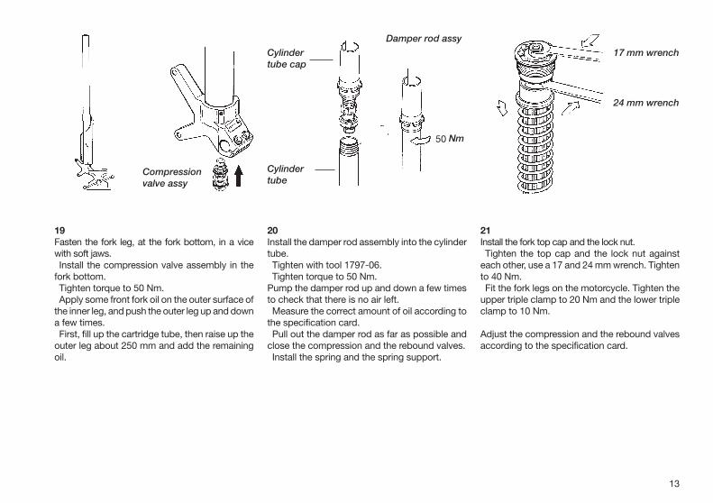
19Fasten the fork leg, at the fork bottom, in a vicewith soft jaws.Install the compression valve assembly in the
fork bottom.Tighten torque to 50 Nm.Apply some front fork oil on the outer surface of
the inner leg, and push the outer leg up and downa few times.First, fill up the cartridge tube, then raise up the
outer leg about 250 mm and add the remainingoil.
21Install the fork top cap and the lock nut.Tighten the top cap and the lock nut against
each other, use a 17 and 24 mm wrench. Tightento 40 Nm.Fit the fork legs on the motorcycle. Tighten the
upper triple clamp to 20 Nm and the lower tripleclamp to 10 Nm.
Adjust the compression and the rebound valvesaccording to the specification card.
20Install the damper rod assembly into the cylindertube.Tighten with tool 1797-06.Tighten torque to 50 Nm.
Pump the damper rod up and down a few timesto check that there is no air left.Measure the correct amount of oil according to
the specification card.Pull out the damper rod as far as possible and
close the compression and the rebound valves.Install the spring and the spring support.
Compressionvalve assy
60 Nm
Damper rod assy
Cylindertube
Cylindertube cap
17 mm wrench
24 mm wrench
50

14
ØA
ØB
L
Technical specificationsFork lengths and diameters
Length (L) ØA ØBFG YA: 938 (±0.4) mm 55.9 mm 59.2 mmFG HO: 940 (±0.4) mm 53.9 mm 59.3 mmFG KT: 933 (±0.4) mm 54.0 mm 60.0 mmFG KA: 940 (±0.4) mm 53.9 mm 59.3 mmFG SU: 938 (±0.4) mm 53.9 mm 59.3 mm
ØA, upper: Ø mm (±0.02 mm)ØB, lower: Ø mm (±0.02 mm)
Rebound and compression adjustmentRefer to mounting instruction for set-up data.Maximum open rebound: 35 clicksCompression: 22 clicks
Free Spring Length:All forks: 467 mm (service limit 460 mm).
Spring pre-load:Maximum allowed adjustment range 3-13 mm.
Optional spring rate:2428-37: 3.7 N/mm2428-39: 3.9 N/mm2428-41: 4.1 N/mm2428-43: 4.3 N/mm2428-45: 4.5 N/mm2428-47: 4.7 N/mm2428-49: 4.9 N/mm
Oil level:Oil capacity in each front fork leg is approximately540 cc.See mounting instruction for recommended oil
level.Adjustment range: 80-130 mm.
CAUTION!Use only Öhlins high performance front fork fluidNo. 5 (1311-01).
Loctite glue:270 for fork bottom thread.
Tighten torque:Triple clamp bolt: Top = 20 Nm, Bottom = 10 NmCompression valve: 50 Nm (Base valve).Cylinder tube cap (cartridge tube): 50 NmCompression valve, 8 mm nut 8 Nm.Rebound valve, 8 mm nut 8 Nm.
Grease:Öhlins Front Fork grease 170-01.
Service intervals:Every 20 hours.
60
225
320
At temperatures below 5° use Front fork fluid 01302-02

15
Spare partsPos. Part No. Pcs. Description Type/remarks
1 02385-01 1 Spring adjuster2 02437-20 1 Spring support3 02428-xx 1 Spring see spec. card4 02551-0x 1 Forkleg outer see spec. card5 02332-11 1 Sticker6 02409-01 1 Guide sleeve7 02547-01 1 Bushing8 02412-01 1 Washer9 02410-03 1 Seal
10 02015-01 1 Circlip11 02411-03 1 Scraper12 02539-01 1 Cylinder tube13 00557-05 1 Circlip14 02521-02 1 Spring seat15 02522-xx 1 Spring16 00438-97 1 O-ring17 02523-01 1 Free piston18 00438-99 1 O-ring 00438-98 1 O-ring20 02549-01 1 Bushing21 02486-11 1 Fork leg inner
02486-12 1 Fork leg inner tin-coated optional part22 00438-16 1 O-ring23 - 1 Bottom piece LH see spec. card24 - 1 Bottom piece LH see spec. card25 02314-02 2 Bolt
1
2
3
4
6
7
91011
8
12
13
25 25
24
5
23
22
21
20
1918
1716
15
14
19

16
Spare partsPos. Part No. Pcs. Description Type/remarks
1 01473-02 1 Circlip2 00338-53 1 O-ring3 02321-02 1 Adjustment screw4 01248-01 1 Spring5 00884-04 2 Ball6 02383-01 1 Needle housing7 00438-54 2 O-ring8 02432-01 1 Top cap9 01050-01 1 Screw10 00338-59 1 O-ring11 00438-61 1 O-ring12 02381-01 1 Washer13 02380-01 1 Mutter14 02366-12 1 Adjustment rod15 02384-01 1 Extender16 02434-04 1 Guide sleeve17 02303-01 1 Sleeve, hydraulic stop18 02304-01 1 Hydraulic stop19 00131-05 1 Circlip20 01499-02 1 Circlip21 02526-48 1 Cylinder tube cap22 02059-01 1 Bushing holder23 00338-19 1 O-ring24 00110-03 1 Bushing25 02528-01 1 Washer26 02388-01 1 Shaft27 02063-02 1 Spring
1
7
6
1213
14
23
8
26
27
11
15
16
17
18
1920
21
22232425
Rebound valve andcompression valve
Base valve
4
5
10
9

17
Comp. valveReb. valve Spare partsPos. Part No. Pcs. Description Type/remarks
28 00438-31 1 O-ring29 02356-03 1 Rebound needle30 02322-01 1 Spring31 02320-04 1 Piston holder32 - Clamp washer see spec. card33 - Shims stack see spec. card34 02520-01 1 Piston rebound35 01447-02 1 Piston ring36 - Shims see spec. card37 - Clamp washer see spec. card38 00153-01 1 Washer39 00430-05 1 Nut
40 00430-05 1 Nut41 00153-01 1 Washer42 02056-01 1 One-way valve seat43 00530-18 3 Shim44 01149-01 1 Wave washer45 00530-22 1 Shim46 00438-03 1 O-ring47 02406-01 1 Piston48 0018x-xx - Shims see spec. card49 00641-01 1 Clamp washer see spec. card50 00438-02 1 O-ring51 02054-04 1 End piece52 01242-08 1 Adjustment needle see spec. card53 01248-01 1 Spring54 00884-04 2 Ball55 00338-53 1 O-ring56 01473-02 1 Circlip
57 02443-02 1 Triple clamp, upper FGHO79102448-02 1 Triple clamp, upper FGKA79102445-02 1 Triple clamp, upper FGSU791
58 02449-01 1 Triple clamp, lower FGHO79102449-02 1 Triple clamp, lower FGSU79102449-03 1 Triple clamp, lower FGKA791
Fork crowns
57
58
40
41
42
43
44
45
46
47
48
49
50
51
5253545556
29
30
31
32
34
35
36
37
39
33
38
28
Triple clamp

18
General handling set-up Front suspension.
Front fork travel is not used to its fullcapacity. Harsh feeling, front wheel grip isnot satisfactory in bumpy turns.Suspension too hard.
• Decrease the front forkcompression damping.
• Change to softer springs.
Suspension bottoming, too soft duringentire travel.Spring too weak or compression damping too soft.
• Increase oil level 5 mm.• Increase compression damping.• Change to stiffer springs.
Suspension bottoming, but can handlesmaller bumps.Damping force not progressive enough.
• Increase the oil level.
Can handle smaller bumps but is too hardduring the last part of the travel.Damping force is too progressive.
• Decrease the oil level.
Front end feels low, initially feels soft, but isnot bottoming.The initial spring rate is too soft or spring pre-load is too low.
• Increase the spring pre-load.
Feels harsh over small bumps, but using fullwheel travel.Too much spring pre-load or too much compres-sion damping.
• Increase the oil level or changeto softer springs.
• Decrease the compressiondamping.
• Decrease the spring pre-load.• Clean the oil seals and scrapers.
Use Öhlins grease 170-01 forregreasing.
Can handle the first in a series of bumps butfeels hard after a few more bumps. Frontalgrip insufficient in rough and bumpy turns.Too much rebound damping.
• Decrease the rebound damping.
Front end rebound too fast after a bump.Front wheel grip insufficient in bumpycurves.Not enough rebound damping, or too muchspring preload
• Increase the rebound damping.• Decrease the spring pre-load.
Front end ”ploughs”, understeers.Shallow front fork angle. Front end too high incomparison to rear end.
• Decrease the front forkcompression damping.
• Raise the fork legs approximately5 mm in the triple clamp.
• Change to softer fork springs.
Front end unstable at high speed, unstablewhen accelerating out of curves.Front fork angle too steep. Front end too low incomparison to rear end.
• Lower the fork legs approximately5 mm in triple clamp.
• Change the front fork springs toharder ones.
Front end unstable during deceleration.Front fork angle too steep during braking. Frontend too low or rear end too high.
• Increase the oil level in the front fork.• Change to harder fork springs.• Increase the front fork
compression damping.
Front end falls into the curves (oversteering)especially in sand.Steep front fork angle. Front end too low in com-parison to rear end.
• Increase the front forkcompression damping.
• Change to harder springs.• Lower fork leg approximately
5 mm in the triple clamp.

19
MaintenanceTelescopic front forks depend on smooth, frictionfree action. Make sure your forks are regularly serv-iced.Do not use strong solvents, such as brake cleaner,
to clean the front forks. This will dry out the sealsand the steel tubes and cause friction or leakage.
After every raceClean externally and spray with an all-purpose oilafter washing with detergent.Check externally for damage.Put a little Öhlins grease (170-01) on the steel tubes
and work it in by pushing the fork up and down.
Every 20 hoursDismantle the fork and check all parts for wear anddamage, replace if necessary, see Dismantling.
Cleaning the scrapersThe purpose of the scrapers is to protect the forktube from dust and dirt. However, dirt may aftersome time end up behind the scrapers. If thisdirt is not removed there is risk that the oil seal-ing rings will start to leak.Lift the scrapers out of the outer tubes with the
help of a screwdriver and slide them downward.Clean the scrapers, the outer tubes and the fronttubes thoroughly, then oil them with Öhlins frontfork fluid No. 5 (1311-01). When done, simplyremount the scrapers by pushing them into theouter tubes.
NOTE!Discarded Öhlins products should be handledover to an authorized work shop or distributor forproper disposal.
NOTE!Use only Öhlins high performance front fork fluidNo. 5 (1311-01).
Breather plug front forkMake sure to ventilate the telescopic fork at regu-lar intervals. Put the motorcycle on a stand sothe front wheel is clear of the ground, then loosenthe vent screws to rid the inside of the fork ofexcess pressure.
CAUTION!Too high pressure inside of the fork may causeleakage. If this is the case, open the breather plugsbefore replacing the seals.
Maintenance intervalsItem After break-in Every race Every 20 hours As requiredFront forksInspect and adjust x x - xReplace oil x - xReplace oil seal - - - x
Front fork oil sealand dust sealClean and lube x x - -
Scraper
Breatherplug
At temperatures below 5° use Front fork fluid 01302-02

Öhlins Racing AB, Box 722, S-194 27 Upplands Väsby, Sweden Phone +46 8 590 025 00, Fax +46 8 590 025 80
Your Öhlins dealer:
More infowww.ohlins.com
0729
5-27
OM
Fro
nt F
ork
48 M
XF
2007
Issu
ed 2
006
11 2
2
![DS MXF 614130 [E-mail]33](https://static.fdocuments.us/doc/165x107/615bde1d49937e585c75f1d4/ds-mxf-614130-e-mail33.jpg)