Owner Instructions - LVC · PDF fileOriginal instructions Warning! Read instructions before...
28
Original instructions Warning! Read instructions before using the machine www.numatic.com TRO 650 Ride-on Scrubber Dryer Owner Instructions TRO 650
Transcript of Owner Instructions - LVC · PDF fileOriginal instructions Warning! Read instructions before...

Original instructionsWarning! Read instructions before using the machine
www.numatic.com
TRO 650Ride-on
Scrubber Dryer
Owner Instructions
TRO 650
2
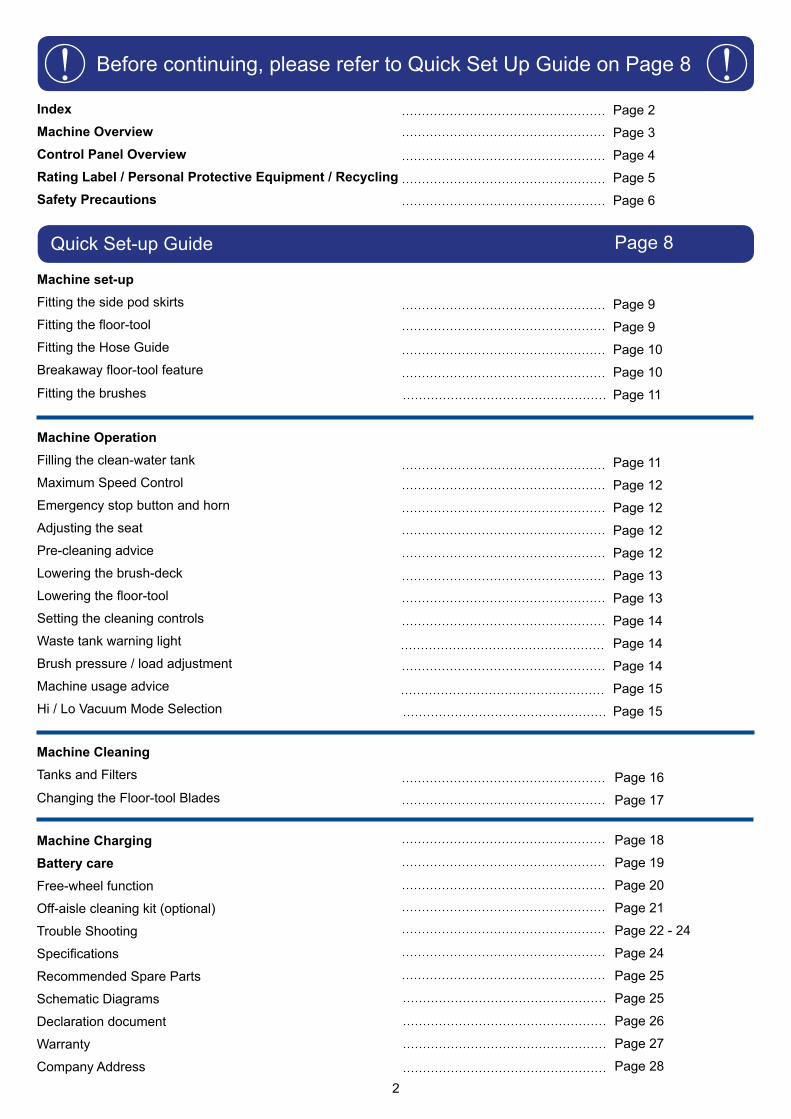
Quick Set-up Guide Page 8
Before continuing, please refer to Quick Set Up Guide on Page 8! !Page 2
Page 3
Page 4
Page 5
Page 6
Page 9
Page 9
Page 10
Page 10
Page 11
Page 11
Page 12
Page 12
Page 12
Page 12
Page 13
Page 13
Page 14
Page 14
Page 14
Page 15
Page 15
Page 16
Page 17
IndexMachine OverviewControl Panel OverviewRating Label / Personal Protective Equipment / RecyclingSafety Precautions
Machine set-upFitting the side pod skirts
Fitting the floor-tool
Fitting the Hose Guide
Breakaway floor-tool feature
Fitting the brushes
Machine Operation
Filling the clean-water tank
Maximum Speed Control
Emergency stop button and horn
Adjusting the seat
Pre-cleaning advice
Lowering the brush-deck
Lowering the floor-tool
Setting the cleaning controls
Waste tank warning light
Brush pressure / load adjustment
Machine usage advice
Hi / Lo Vacuum Mode Selection
Machine Cleaning Tanks and Filters
Changing the Floor-tool Blades
Machine ChargingBattery careFree-wheel function
Off-aisle cleaning kit (optional)
Trouble Shooting
Specifications
Recommended Spare Parts
Schematic Diagrams
Declaration document
Warranty
Company Address
Page 18
Page 19
Page 20
Page 21
Page 22 - 24
Page 24
Page 25
Page 25
Page 26
Page 27
Page 28
3
1314
6
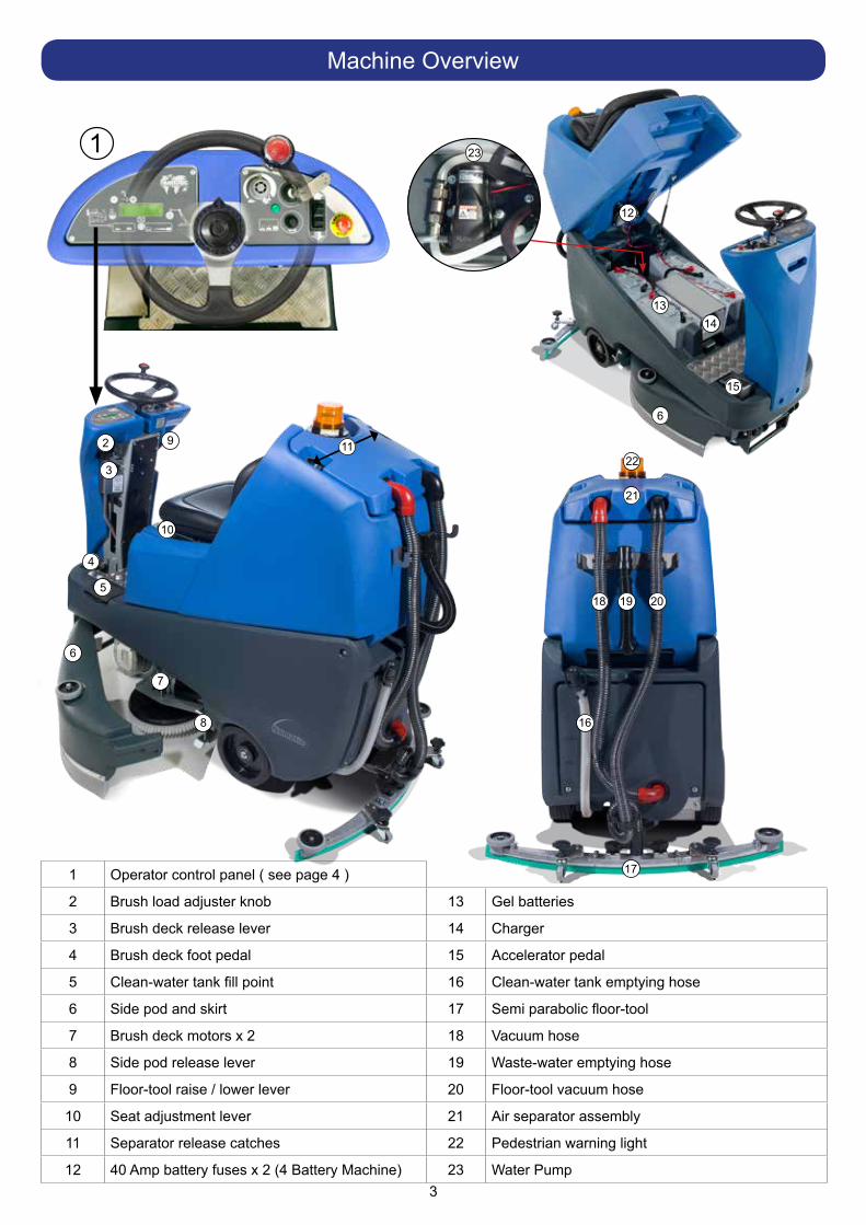
1 Operator control panel ( see page 4 )
2 Brush load adjuster knob 13 Gel batteries
3 Brush deck release lever 14 Charger
4 Brush deck foot pedal 15 Accelerator pedal
5 Clean-water tank fill point 16 Clean-water tank emptying hose
6 Side pod and skirt 17 Semi parabolic floor-tool
7 Brush deck motors x 2 18 Vacuum hose
8 Side pod release lever 19 Waste-water emptying hose
9 Floor-tool raise / lower lever 20 Floor-tool vacuum hose
10 Seat adjustment lever 21 Air separator assembly
11 Separator release catches 22 Pedestrian warning light
12 40 Amp battery fuses x 2 (4 Battery Machine) 23 Water Pump
Machine Overview
12
22
21
18 19 20
16
17
11
10
92
3
4
5
6
7
8
15
1 23
4
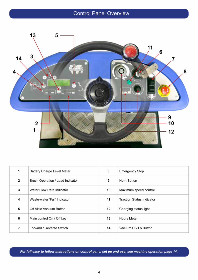
Control Panel Overview
1 Battery Charge Level Meter 8 Emergency Stop
2 Brush Operation / Load Indicator 9 Horn Button
3 Water Flow Rate Indicator 10 Maximum speed control
4 Waste-water ‘Full’ Indicator 11 Traction Status Indicator
5 Off Aisle Vacuum Button 12 Charging status light
6 Main control On / Off key 13 Hours Meter
7 Forward / Reverse Switch 14 Vacuum Hi / Lo Button
For full easy to follow instructions on control panel set up and use, see machine operation page 14.
12
4
3
5
116
8
7
91012
13
14
5
About the Machine
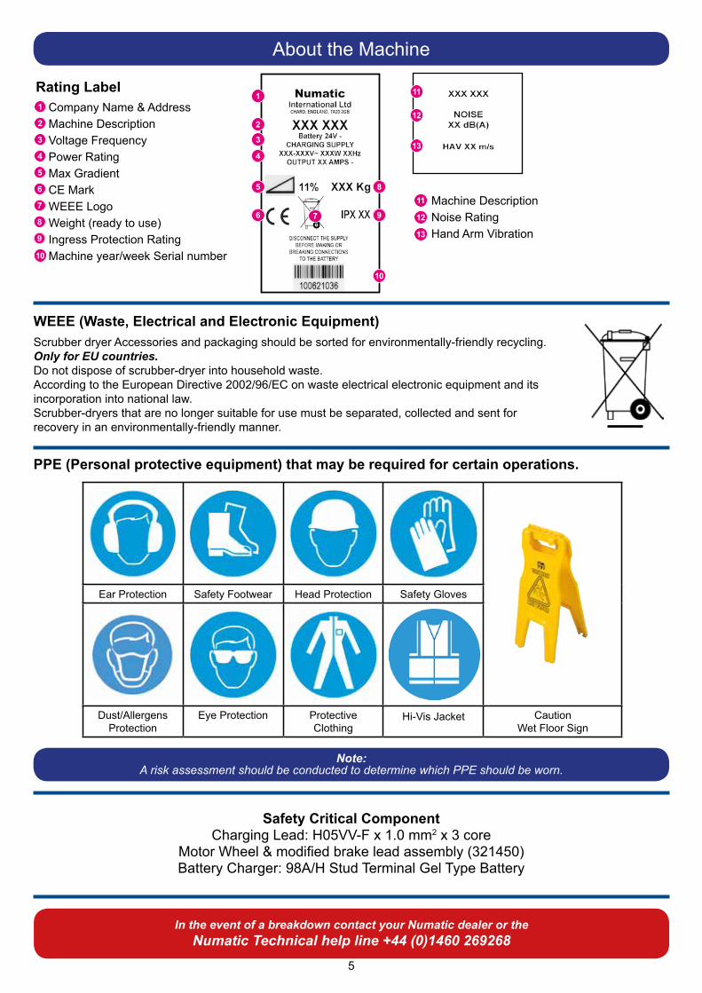
WEEE (Waste, Electrical and Electronic Equipment)Scrubber dryer Accessories and packaging should be sorted for environmentally-friendly recycling.Only for EU countries.Do not dispose of scrubber-dryer into household waste.According to the European Directive 2002/96/EC on waste electrical electronic equipment and its incorporation into national law.Scrubber-dryers that are no longer suitable for use must be separated, collected and sent for recovery in an environmentally-friendly manner.
Safety Critical ComponentCharging Lead: H05VV-F x 1.0 mm2 x 3 core
Motor Wheel & modified brake lead assembly (321450)Battery Charger: 98A/H Stud Terminal Gel Type Battery
1
2
3
4
5
6 7
8
9
In the event of a breakdown contact your Numatic dealer or theNumatic Technical help line +44 (0)1460 269268
10
Rating Label1
2
3
4
5
6
7
8
9
Company Name & AddressMachine DescriptionVoltage FrequencyPower RatingMax GradientCE MarkWEEE LogoWeight (ready to use)Ingress Protection RatingMachine year/week Serial number10
12
11
13
11
12
13
Machine DescriptionNoise RatingHand Arm Vibration
Ear Protection Safety Footwear Head Protection Safety Gloves
Dust/Allergens Protection
Eye Protection Protective Clothing
Hi-Vis Jacket Caution Wet Floor Sign
Note:A risk assessment should be conducted to determine which PPE should be worn.
PPE (Personal protective equipment) that may be required for certain operations.

6
As with all electrical equipment care and attention must be exercised at all times during its use, in addition to ensuring that routine and preventative maintenance is carried out periodically in order to ensure its safe operation. Failure to carry out maintenance as necessary, including the replacement of parts to the correct standard could render this equipment unsafe and the manufacturer can accept no responsibility or liability in this
respect. When ordering spare parts always quote the Model Number / Serial Number specified on the Rating Plate.Warning do not use on slopes exceeding 11%.
This appliance is not intended for use by persons (including children) with reduced physical, sensory or mental capabilities, or lack of experience and knowledge, unless they have been given supervision or instruction concerning use of the appliance by a person responsible for their safety.Children should be supervised to ensure that they do not play with the appliance. When detergents or other liquids are used, read the manufacturer’s instructions.
This machine is not suitable for picking-up hazardous dust.Do not use on surfaces having a gradient exceeding that marked on the appliance.The machine is not to be stored outdoors in wet conditions.This machine is for indoor use only.Read the instruction manual before using the appliance.This product meets the requirements of IEC 60335-2-72 Sub Clause 20.1.
NOTESThis machine is also suitable for commercial use, for example in hotels, schools, hospitals, factories, shops and offices for other than normal housekeeping purposes.
• Ensure only competent persons unpack/assemble the machine.• Keep your machine clean.• Keep your brushes in good condition.• Replace any worn or damaged parts immediately.• Regularly examine the charger lead for damage, such as cracking or ageing. If damage is found, replace the lead before further use.• Only replace the charger lead with the correct Numatic approved replacement parts.• Ensure that the work area is clear of obstructions and / or people.• Ensure that the working area is well illuminated.• Pre-sweep the area to be cleaned.
• Use steam cleaners or pressure washers to clean the machine or use in the rain.• Attempt machine maintenance or cleaning unless the power plug has been removed from the supply outlet, if the machine is in charge mode or remove the key if in normal use.• Allow any inexperienced repairs. Call the experts.• Strain charger lead or try to unplug by pulling on charger lead.• Leave the brush deck in the lowered position when not in use. • Allow the machine to be used by inexperienced or unauthorised operators or without appropriate training.• Expect the machine to provide trouble-free, reliable operation unless maintained correctly.• Run the machine over power cable during operation.
ORIGINAL INSTRUCTIONSREAD MANUAL BEFORE USE
Information for Scrubber Dryer
WARNING
CAUTION
DO
DON’T
Component Interval Inspect forMains Lead DAILY Scuffing, cracks, splits, conductors showing
Brushes DAILY Bristle damage, wear, drive collar wear
Squeegee Blade BEFORE EACH USE Wear, cracks, splits
Filters BEFORE EACH USE Clogging and debris retention
Tanks AFTER EACH USE Rinse dirty water tank after use
7
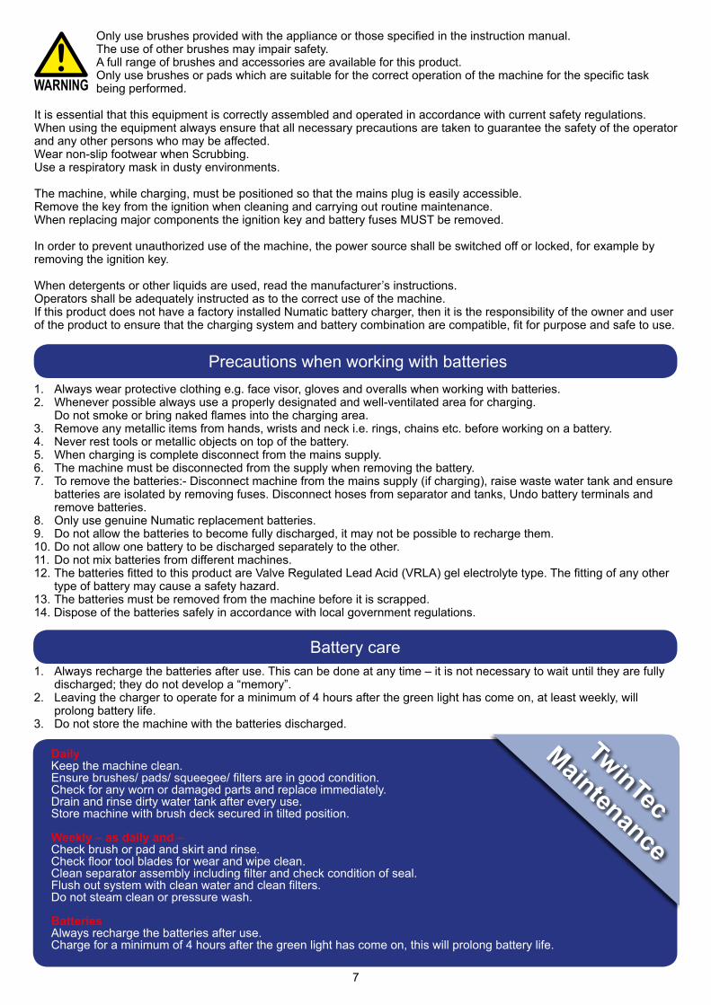
Only use brushes provided with the appliance or those specified in the instruction manual.The use of other brushes may impair safety.A full range of brushes and accessories are available for this product.Only use brushes or pads which are suitable for the correct operation of the machine for the specific task being performed.
It is essential that this equipment is correctly assembled and operated in accordance with current safety regulations.When using the equipment always ensure that all necessary precautions are taken to guarantee the safety of the operator and any other persons who may be affected.Wear non-slip footwear when Scrubbing.Use a respiratory mask in dusty environments.
The machine, while charging, must be positioned so that the mains plug is easily accessible.Remove the key from the ignition when cleaning and carrying out routine maintenance.When replacing major components the ignition key and battery fuses MUST be removed.
In order to prevent unauthorized use of the machine, the power source shall be switched off or locked, for example by removing the ignition key.
When detergents or other liquids are used, read the manufacturer’s instructions.Operators shall be adequately instructed as to the correct use of the machine.If this product does not have a factory installed Numatic battery charger, then it is the responsibility of the owner and user of the product to ensure that the charging system and battery combination are compatible, fit for purpose and safe to use.
WARNING
1. Always wear protective clothing e.g. face visor, gloves and overalls when working with batteries.2. Whenever possible always use a properly designated and well-ventilated area for charging. Do not smoke or bring naked flames into the charging area.3. Remove any metallic items from hands, wrists and neck i.e. rings, chains etc. before working on a battery.4. Never rest tools or metallic objects on top of the battery.5. When charging is complete disconnect from the mains supply.6. The machine must be disconnected from the supply when removing the battery. 7. To remove the batteries:- Disconnect machine from the mains supply (if charging), raise waste water tank and ensure batteries are isolated by removing fuses. Disconnect hoses from separator and tanks, Undo battery terminals and remove batteries. 8. Only use genuine Numatic replacement batteries. 9. Do not allow the batteries to become fully discharged, it may not be possible to recharge them. 10. Do not allow one battery to be discharged separately to the other. 11. Do not mix batteries from different machines. 12. The batteries fitted to this product are Valve Regulated Lead Acid (VRLA) gel electrolyte type. The fitting of any other type of battery may cause a safety hazard.13. The batteries must be removed from the machine before it is scrapped.14. Dispose of the batteries safely in accordance with local government regulations.
Precautions when working with batteries
1. Always recharge the batteries after use. This can be done at any time – it is not necessary to wait until they are fully discharged; they do not develop a “memory”. 2. Leaving the charger to operate for a minimum of 4 hours after the green light has come on, at least weekly, will prolong battery life.3. Do not store the machine with the batteries discharged.
Battery care
DailyKeep the machine clean.Ensure brushes/ pads/ squeegee/ filters are in good condition.Check for any worn or damaged parts and replace immediately.Drain and rinse dirty water tank after every use.Store machine with brush deck secured in tilted position.
Weekly – as daily and – Check brush or pad and skirt and rinse.Check floor tool blades for wear and wipe clean.Clean separator assembly including filter and check condition of seal.Flush out system with clean water and clean filters.Do not steam clean or pressure wash.
BatteriesAlways recharge the batteries after use.Charge for a minimum of 4 hours after the green light has come on, this will prolong battery life.
TwinTec
Maintenance
8
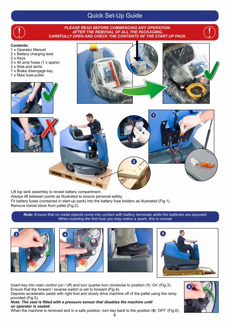
Lift top tank assembly to reveal battery compartment.Always lift between points as illustrated to ensure personal safety.Fit battery fuses (contained in start-up pack) into the battery fuse holders as illustrated (Fig.1).Remove transit block from pallet (Fig.2).
Contents:1 x Operator Manual2 x Battery charging lead2 x Keys3 x 40 amp fuses (1 x spare)2 x Side pod skirts1 x Brake disengage key1 x Maxi fuse-puller
Quick Set-Up Guide
PLEASE READ BEFORE COMMENCING ANY OPERATION.AFTER THE REMOVAL OF ALL THE PACKAGING,
CAREFULLY OPEN AND CHECK THE CONTENTS OF THE START UP PACK. !!
1
Note: Ensure that no metal objects come into contact with battery terminals while the batteries are exposed.When inserting the first fuse you may notice a spark, this is normal.
1a
2
3
6
5
Insert key into main control (on / off) and turn quarter-turn clockwise to position (1) ‘On’ (Fig.3).Ensure that the forward / reverse switch is set to forward (Fig.4).Depress accelerator pedal with right foot and slowly drive machine off of the pallet using the ramp provided (Fig.5).Note: The seat is fitted with a pressure sensor that disables the machine untilan operator is seated. When the machine is removed and in a safe position, turn key back to the position (0) ‘OFF’ (Fig.6).
4
9
Machine Set-Up
ALWAYS ENSURE THAT THE MACHINE IS SWITCHED OFF BEFORE MAKING ANY ADJUSTMENTS! !
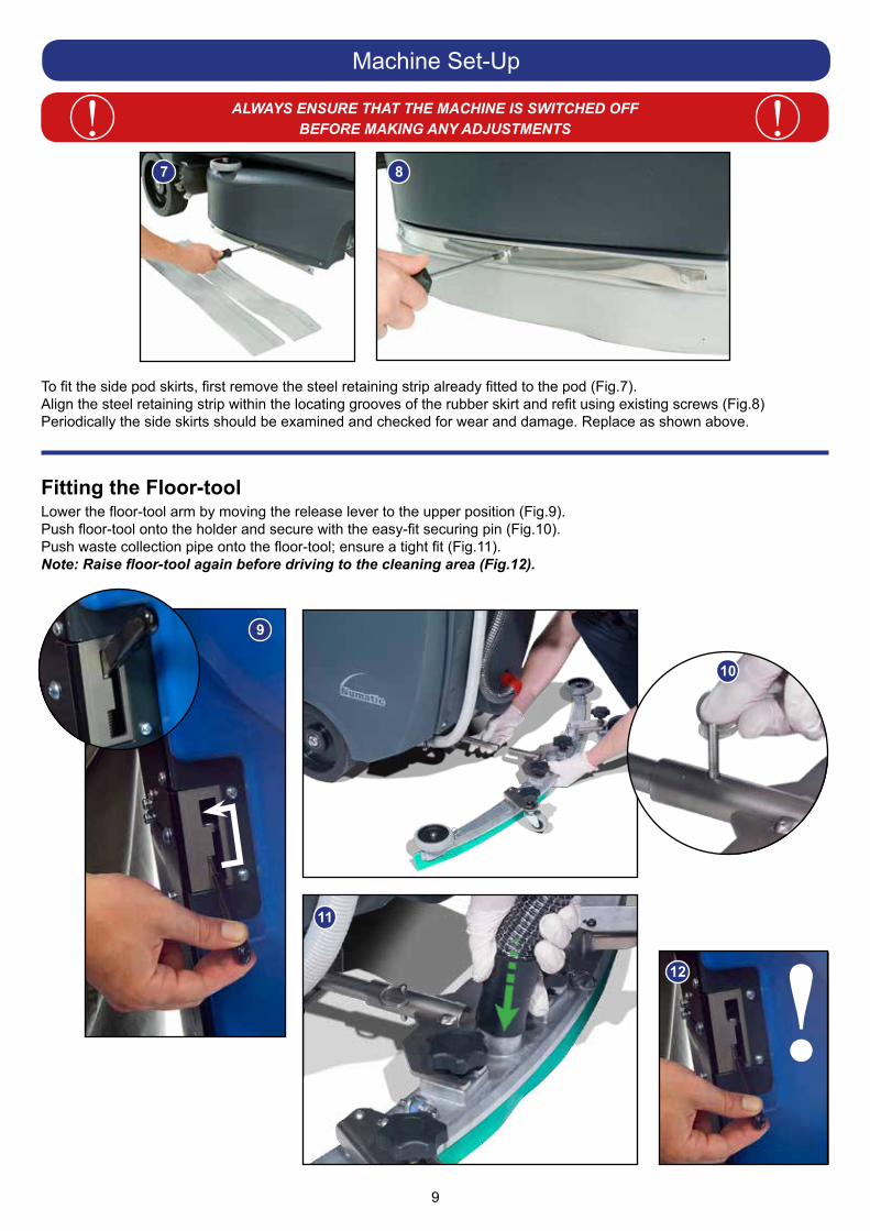
Fitting the Floor-tool
To fit the side pod skirts, first remove the steel retaining strip already fitted to the pod (Fig.7).Align the steel retaining strip within the locating grooves of the rubber skirt and refit using existing screws (Fig.8)Periodically the side skirts should be examined and checked for wear and damage. Replace as shown above.
Lower the floor-tool arm by moving the release lever to the upper position (Fig.9).Push floor-tool onto the holder and secure with the easy-fit securing pin (Fig.10).Push waste collection pipe onto the floor-tool; ensure a tight fit (Fig.11).Note: Raise floor-tool again before driving to the cleaning area (Fig.12).
!
7 8
9
10
11
12
10
Machine Operation
Breakaway Floor-tool
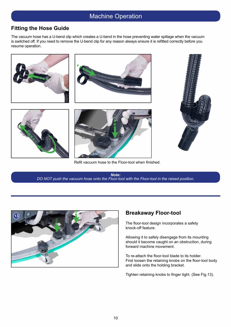
Refit vacuum hose to the Floor-tool when finished.
The vacuum hose has a U-bend clip which creates a U-bend in the hose preventing water spillage when the vacuum is switched off. If you need to remove the U-bend clip for any reason always ensure it is refitted correctly before you resume operation.
Fitting the Hose Guide
Note:DO NOT push the vacuum hose onto the Floor-tool with the Floor-tool in the raised position.
The floor-tool design incorporates a safetyknock-off feature.
Allowing it to safely disengage from its mounting should it become caught on an obstruction, during forward machine movement.
To re-attach the floor-tool blade to its holder.First loosen the retaining knobs on the floor-tool body and slide onto the holding bracket. Tighten retaining knobs to finger tight. (See Fig.13).
13
11
Machine Set-Up
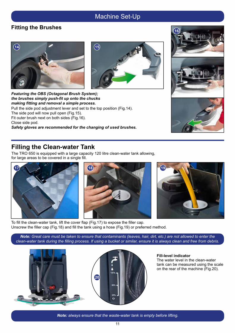
Featuring the OBS (Octagonal Brush System); the brushes simply push-fit up onto the chucks making fitting and removal a simple process.Pull the side pod adjustment lever and set to the top position (Fig.14).The side pod will now pull open (Fig.15).Fit outer brush next on both sides (Fig.16).Close side pod.Safety gloves are recommended for the changing of used brushes.
Fitting the Brushes
14 15
16
The TRO 650 is equipped with a large capacity 120 litre clean-water tank allowing,for large areas to be covered in a single fill.
To fill the clean-water tank, lift the cover flap (Fig.17) to expose the filler cap.Unscrew the filler cap (Fig.18) and fill the tank using a hose (Fig.19) or preferred method.
Filling the Clean-water Tank
17 18 19
Note: Great care must be taken to ensure that contaminants (leaves, hair, dirt, etc.) are not allowed to enter the clean-water tank during the filling process. If using a bucket or similar, ensure it is always clean and free from debris.
Fill-level indicatorThe water level in the clean-water tank can be measured using the scale on the rear of the machine (Fig.20).
20
Note: always ensure that the waste-water tank is empty before lifting.
12
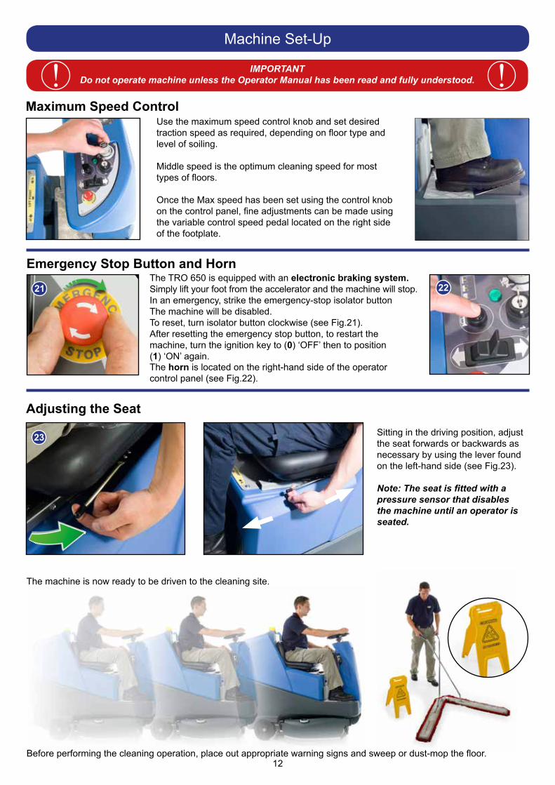
The machine is now ready to be driven to the cleaning site.
Before performing the cleaning operation, place out appropriate warning signs and sweep or dust-mop the floor.
Machine Set-Up
IMPORTANTDo not operate machine unless the Operator Manual has been read and fully understood. !!
Use the maximum speed control knob and set desired traction speed as required, depending on floor type and level of soiling.
Middle speed is the optimum cleaning speed for most types of floors.
Once the Max speed has been set using the control knob on the control panel, fine adjustments can be made using the variable control speed pedal located on the right side of the footplate.
Maximum Speed Control
Emergency Stop Button and HornThe TRO 650 is equipped with an electronic braking system.Simply lift your foot from the accelerator and the machine will stop.In an emergency, strike the emergency-stop isolator button The machine will be disabled.To reset, turn isolator button clockwise (see Fig.21).After resetting the emergency stop button, to restart the machine, turn the ignition key to (0) ‘OFF’ then to position(1) ‘ON’ again.The horn is located on the right-hand side of the operator control panel (see Fig.22).
21 22
Sitting in the driving position, adjust the seat forwards or backwards as necessary by using the lever found on the left-hand side (see Fig.23).
Note: The seat is fitted with a pressure sensor that disables the machine until an operator is seated.
Adjusting the Seat
23
13
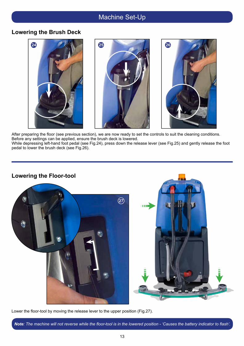
Lower the floor-tool by moving the release lever to the upper position (Fig.27).
Lowering the Floor-tool
27
Note: The machine will not reverse while the floor-tool is in the lowered position - ‘Causes the battery indicator to flash’.
Machine Set-Up
After preparing the floor (see previous section), we are now ready to set the controls to suit the cleaning conditions.Before any settings can be applied, ensure the brush deck is lowered.While depressing left-hand foot pedal (see Fig.24), press down the release lever (see Fig.25) and gently release the foot pedal to lower the brush deck (see Fig.26).
Lowering the Brush Deck
24 25 26
14
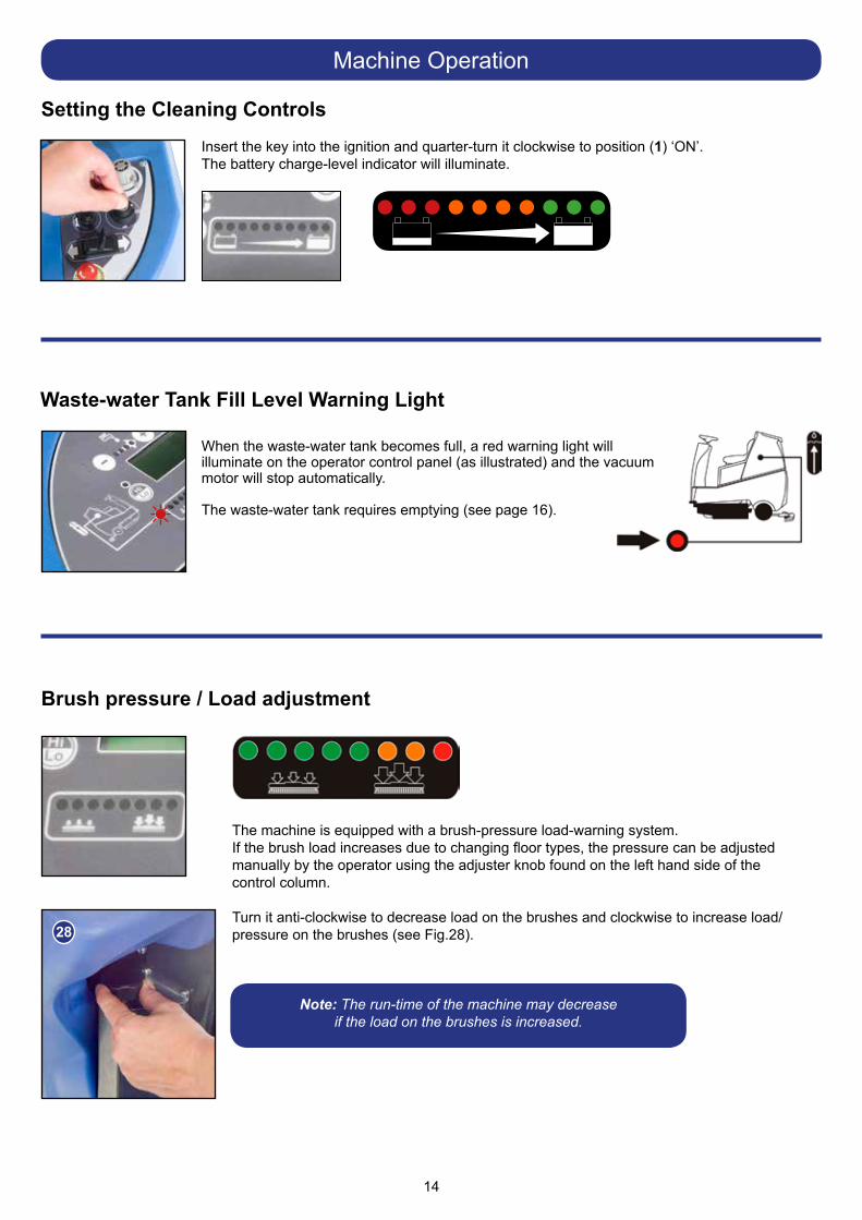
Insert the key into the ignition and quarter-turn it clockwise to position (1) ‘ON’. The battery charge-level indicator will illuminate.
Machine Operation
Setting the Cleaning Controls
Waste-water Tank Fill Level Warning Light
When the waste-water tank becomes full, a red warning light will illuminate on the operator control panel (as illustrated) and the vacuum motor will stop automatically.
The waste-water tank requires emptying (see page 16).
The machine is equipped with a brush-pressure load-warning system.If the brush load increases due to changing floor types, the pressure can be adjusted manually by the operator using the adjuster knob found on the left hand side of the control column.
Turn it anti-clockwise to decrease load on the brushes and clockwise to increase load/pressure on the brushes (see Fig.28).
Note: The run-time of the machine may decrease if the load on the brushes is increased.
Brush pressure / Load adjustment
28
15
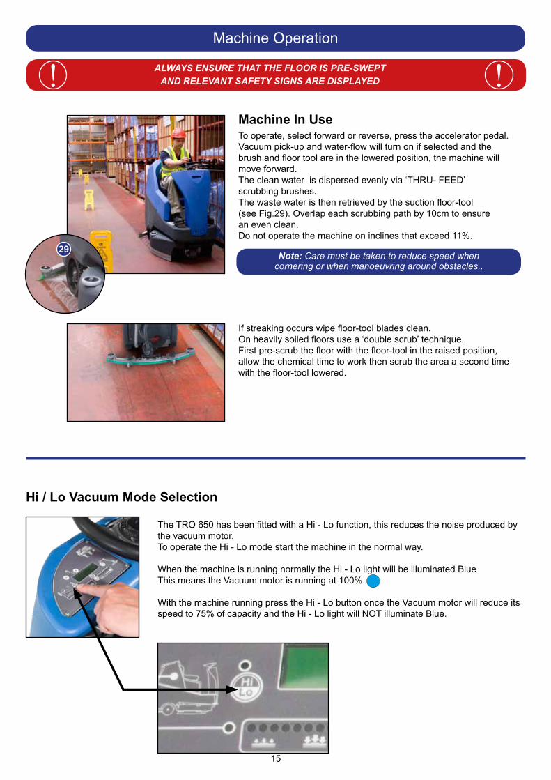
ALWAYS ENSURE THAT THE FLOOR IS PRE-SWEPT AND RELEVANT SAFETY SIGNS ARE DISPLAYED! !
Machine Operation
Note: Care must be taken to reduce speed when cornering or when manoeuvring around obstacles..
Machine In UseTo operate, select forward or reverse, press the accelerator pedal. Vacuum pick-up and water-flow will turn on if selected and the brush and floor tool are in the lowered position, the machine will move forward.The clean water is dispersed evenly via ‘THRU- FEED’ scrubbing brushes. The waste water is then retrieved by the suction floor-tool (see Fig.29). Overlap each scrubbing path by 10cm to ensure an even clean.Do not operate the machine on inclines that exceed 11%.
If streaking occurs wipe floor-tool blades clean.On heavily soiled floors use a ‘double scrub’ technique.First pre-scrub the floor with the floor-tool in the raised position,allow the chemical time to work then scrub the area a second timewith the floor-tool lowered.
The TRO 650 has been fitted with a Hi - Lo function, this reduces the noise produced bythe vacuum motor.To operate the Hi - Lo mode start the machine in the normal way.
When the machine is running normally the Hi - Lo light will be illuminated BlueThis means the Vacuum motor is running at 100%.
With the machine running press the Hi - Lo button once the Vacuum motor will reduce its speed to 75% of capacity and the Hi - Lo light will NOT illuminate Blue.
Hi / Lo Vacuum Mode Selection
29
16
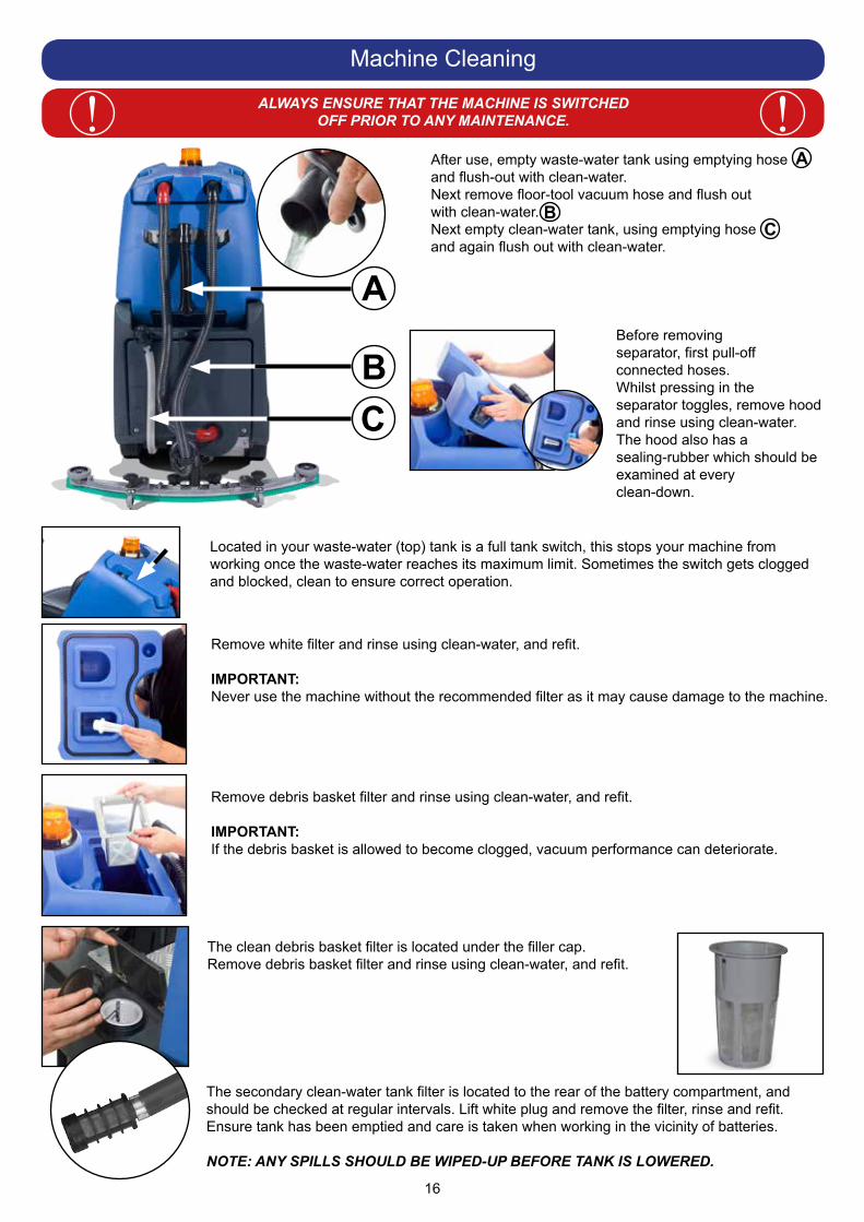
After use, empty waste-water tank using emptying hose and flush-out with clean-water.Next remove floor-tool vacuum hose and flush out with clean-water.Next empty clean-water tank, using emptying hoseand again flush out with clean-water.
A
A
BC
BC
Before removing separator, first pull-off connected hoses.Whilst pressing in the separator toggles, remove hood and rinse using clean-water.The hood also has a sealing-rubber which should be examined at every clean-down.
Remove white filter and rinse using clean-water, and refit.
IMPORTANT:Never use the machine without the recommended filter as it may cause damage to the machine.
Remove debris basket filter and rinse using clean-water, and refit.
IMPORTANT:If the debris basket is allowed to become clogged, vacuum performance can deteriorate.
Located in your waste-water (top) tank is a full tank switch, this stops your machine from working once the waste-water reaches its maximum limit. Sometimes the switch gets clogged and blocked, clean to ensure correct operation.
The secondary clean-water tank filter is located to the rear of the battery compartment, and should be checked at regular intervals. Lift white plug and remove the filter, rinse and refit.Ensure tank has been emptied and care is taken when working in the vicinity of batteries. NOTE: ANY SPILLS SHOULD BE WIPED-UP BEFORE TANK IS LOWERED.
The clean debris basket filter is located under the filler cap.Remove debris basket filter and rinse using clean-water, and refit.
Machine Cleaning
ALWAYS ENSURE THAT THE MACHINE IS SWITCHED OFF PRIOR TO ANY MAINTENANCE.! !
17
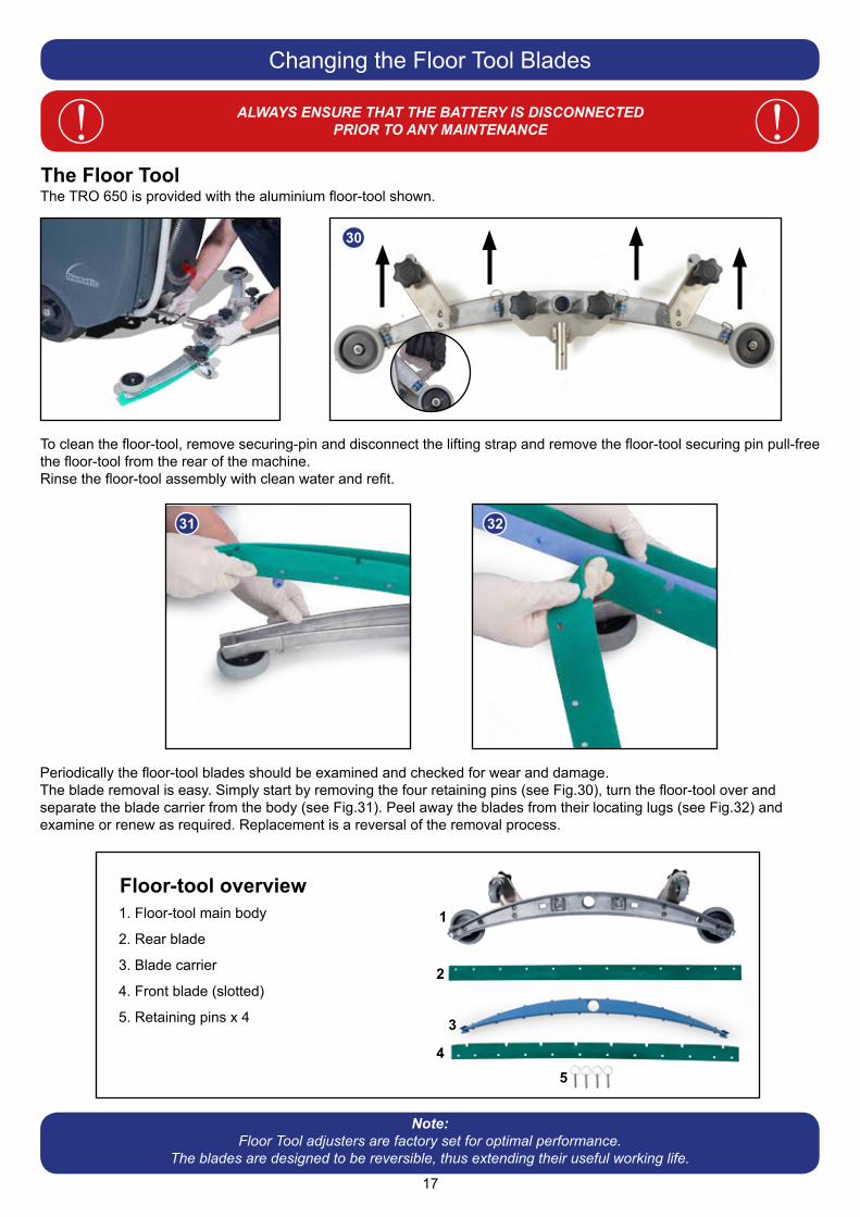
The Floor Tool
Changing the Floor Tool Blades
ALWAYS ENSURE THAT THE BATTERY IS DISCONNECTEDPRIOR TO ANY MAINTENANCE! !
30
31 32
Floor-tool overview1. Floor-tool main body
2. Rear blade
3. Blade carrier
4. Front blade (slotted)
5. Retaining pins x 4
1
2
3
45
Note:Floor Tool adjusters are factory set for optimal performance.
The blades are designed to be reversible, thus extending their useful working life.
To clean the floor-tool, remove securing-pin and disconnect the lifting strap and remove the floor-tool securing pin pull-free the floor-tool from the rear of the machine.Rinse the floor-tool assembly with clean water and refit.
Periodically the floor-tool blades should be examined and checked for wear and damage.The blade removal is easy. Simply start by removing the four retaining pins (see Fig.30), turn the floor-tool over and separate the blade carrier from the body (see Fig.31). Peel away the blades from their locating lugs (see Fig.32) and examine or renew as required. Replacement is a reversal of the removal process.
The TRO 650 is provided with the aluminium floor-tool shown.
18
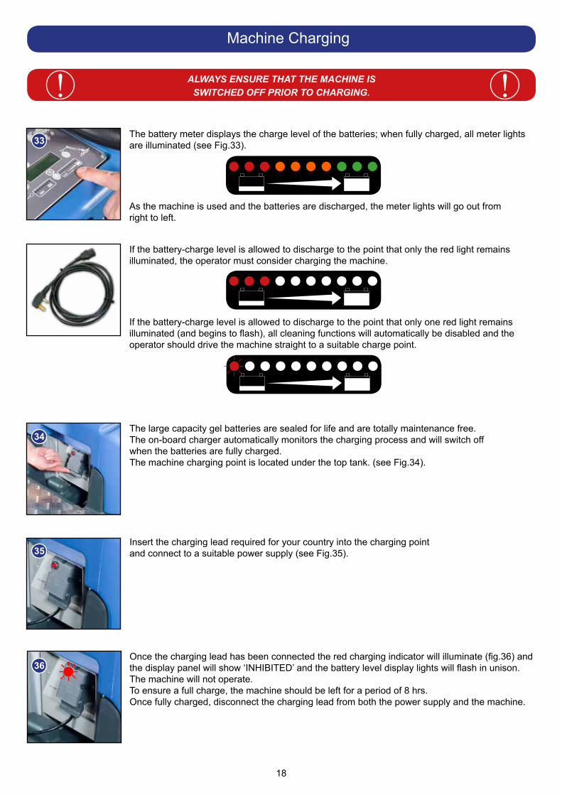
The large capacity gel batteries are sealed for life and are totally maintenance free.The on-board charger automatically monitors the charging process and will switch off when the batteries are fully charged.The machine charging point is located under the top tank. (see Fig.34).
Insert the charging lead required for your country into the charging point and connect to a suitable power supply (see Fig.35).
Once the charging lead has been connected the red charging indicator will illuminate (fig.36) and the display panel will show ‘INHIBITED’ and the battery level display lights will flash in unison.The machine will not operate.To ensure a full charge, the machine should be left for a period of 8 hrs.Once fully charged, disconnect the charging lead from both the power supply and the machine.
Machine Charging
ALWAYS ENSURE THAT THE MACHINE IS SWITCHED OFF PRIOR TO CHARGING.! !
The battery meter displays the charge level of the batteries; when fully charged, all meter lights are illuminated (see Fig.33).
As the machine is used and the batteries are discharged, the meter lights will go out from right to left.
If the battery-charge level is allowed to discharge to the point that only the red light remainsilluminated, the operator must consider charging the machine.
If the battery-charge level is allowed to discharge to the point that only one red light remainsilluminated (and begins to flash), all cleaning functions will automatically be disabled and the operator should drive the machine straight to a suitable charge point.
33
34
35
36
19
Battery Care
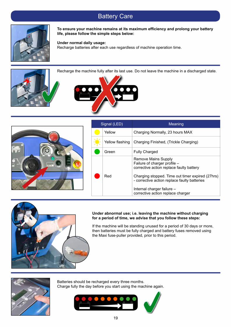
To ensure your machine remains at its maximum efficiency and prolong your battery life, please follow the simple steps below:
Under normal daily usage:Recharge batteries after each use regardless of machine operation time.
Recharge the machine fully after its last use. Do not leave the machine in a discharged state.
Under abnormal use; i.e. leaving the machine without chargingfor a period of time, we advise that you follow these steps:
If the machine will be standing unused for a period of 30 days or more, then batteries must be fully charged and battery fuses removed using the Maxi fuse-puller provided, prior to this period.
Batteries should be recharged every three months. Charge fully the day before you start using the machine again.
Signal (LED) Meaning
Yellow Charging Normally, 23 hours MAX
Yellow flashing Charging Finished, (Trickle Charging)
Green Fully Charged
Red
Remove Mains SupplyFailure of charger profile –corrective action replace faulty battery
Charging stopped. Time out timer expired (27hrs) - corrective action replace faulty batteries
Internal charger failure –corrective action replace charger
20
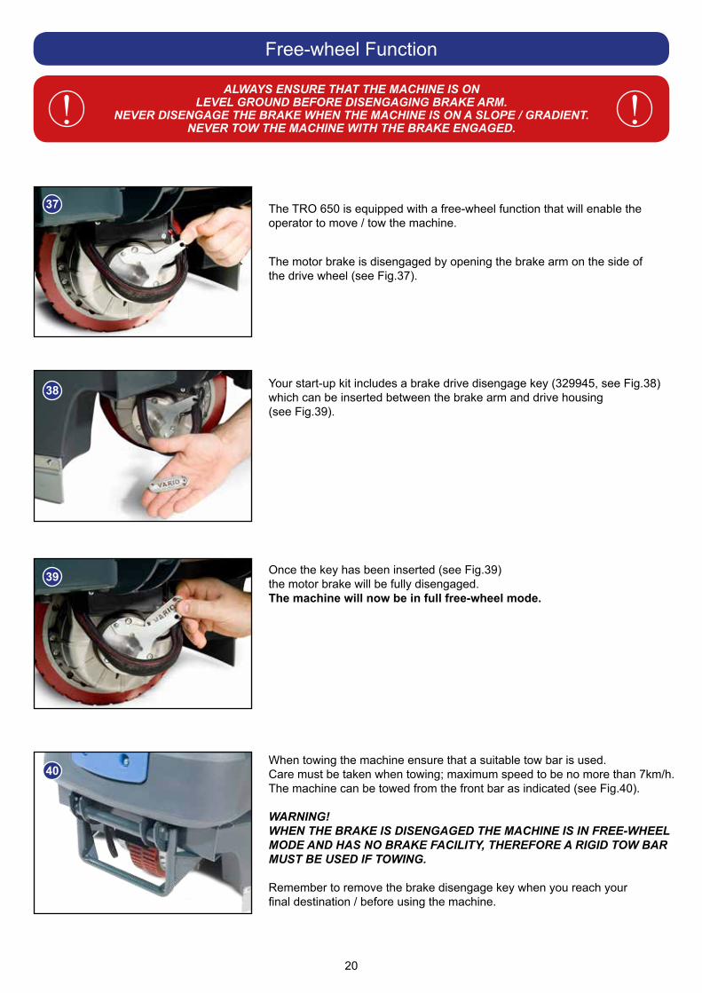
The TRO 650 is equipped with a free-wheel function that will enable the operator to move / tow the machine.
The motor brake is disengaged by opening the brake arm on the side of the drive wheel (see Fig.37).
Your start-up kit includes a brake drive disengage key (329945, see Fig.38) which can be inserted between the brake arm and drive housing (see Fig.39).
Once the key has been inserted (see Fig.39)the motor brake will be fully disengaged.The machine will now be in full free-wheel mode.
When towing the machine ensure that a suitable tow bar is used.Care must be taken when towing; maximum speed to be no more than 7km/h. The machine can be towed from the front bar as indicated (see Fig.40).
WARNING!WHEN THE BRAKE IS DISENGAGED THE MACHINE IS IN FREE-WHEEL MODE AND HAS NO BRAKE FACILITY, THEREFORE A RIGID TOW BAR MUST BE USED IF TOWING.
Remember to remove the brake disengage key when you reach your final destination / before using the machine.
Free-wheel Function
ALWAYS ENSURE THAT THE MACHINE IS ONLEVEL GROUND BEFORE DISENGAGING BRAKE ARM.
NEVER DISENGAGE THE BRAKE WHEN THE MACHINE IS ON A SLOPE / GRADIENT.NEVER TOW THE MACHINE WITH THE BRAKE ENGAGED.
! !
37
38
39
40
21
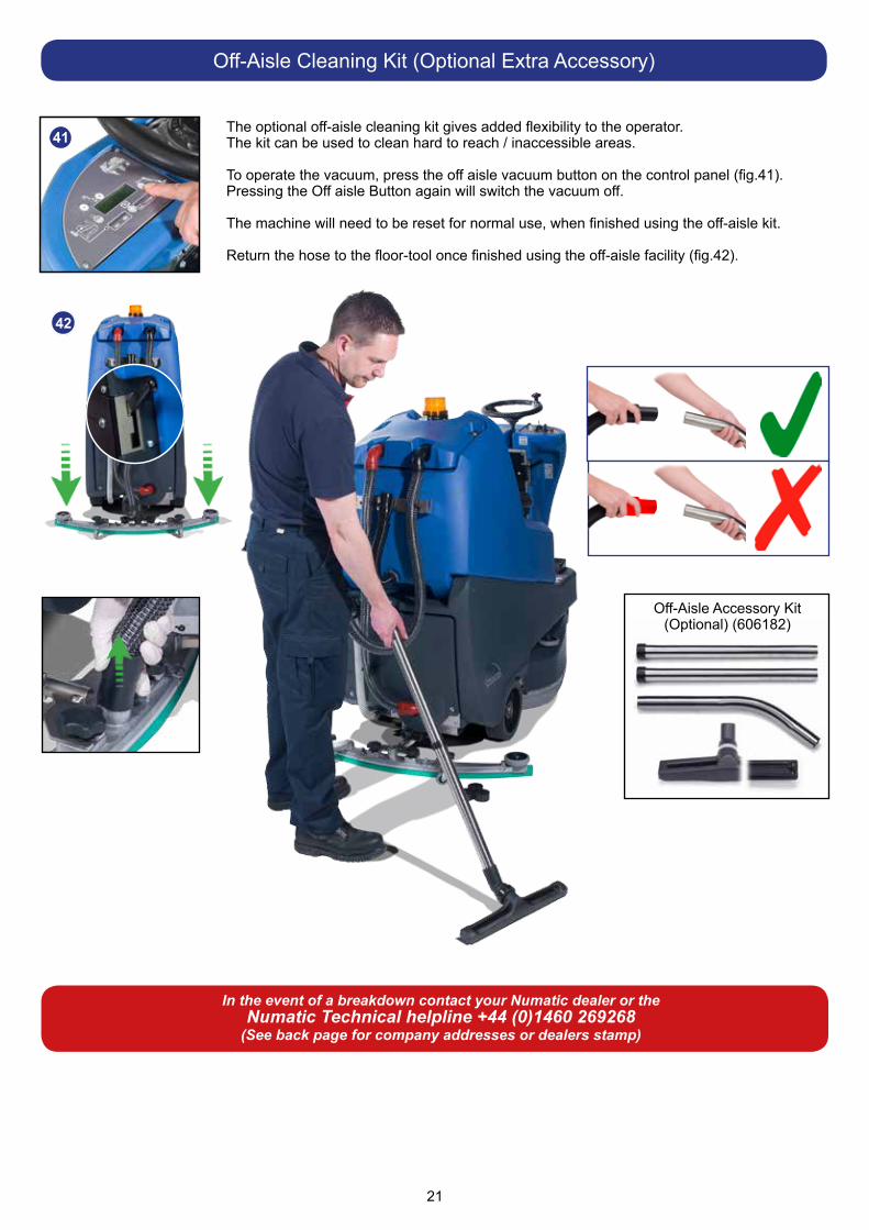
The optional off-aisle cleaning kit gives added flexibility to the operator.The kit can be used to clean hard to reach / inaccessible areas.
To operate the vacuum, press the off aisle vacuum button on the control panel (fig.41).Pressing the Off aisle Button again will switch the vacuum off.
The machine will need to be reset for normal use, when finished using the off-aisle kit.
Return the hose to the floor-tool once finished using the off-aisle facility (fig.42).
Off-Aisle Cleaning Kit (Optional Extra Accessory)
41
Off-Aisle Accessory Kit(Optional) (606182)
In the event of a breakdown contact your Numatic dealer or theNumatic Technical helpline +44 (0)1460 269268
(See back page for company addresses or dealers stamp)
42

22
Gre
en S
tatu
s In
dica
tor
Faul
tP
ossi
ble
Cau
seE
ffect
on
Pro
duct
Inve
stig
ate
the
Follo
win
gA
ctio
n R
equi
red
If fa
ult p
ersi
sts
Gre
en F
lash
ing
War
ning
ligh
t.War
ning
ligh
t flas
hes
expl
aine
d
1 F
lash
with
pau
seB
atte
ries
volta
ge lo
wB
atte
ries
not b
een
char
ged
Pos
sibl
e ba
d co
nnec
tion
betw
een
batte
ries,
con
trolle
r, ch
arge
r or f
uses
ca
used
by
loos
e co
nnec
tions
, da
mag
ed w
iring
, w
ater
ingr
ess
Not
acc
eptin
g ch
arge
due
to fa
ulty
ba
ttery
/cel
l
Cha
rger
not
func
tioni
ng
Ope
ratin
g tim
e se
vere
ly re
duce
d or
mac
hine
will
not
op
erat
e
Che
ck w
hen
mac
hine
last
cha
rged
Sw
itch
OFF
the
mac
hine
: R
emov
e Fu
ses
Che
ck c
onne
ctio
ns to
bat
terie
s, c
harg
er a
nd fu
ses
for l
oose
wire
s or
scr
ews
Che
ck e
ach
batte
ry V
olta
ge in
divi
dual
ly to
det
ect
defe
ct u
nit 1
0.5V
min
Che
ck b
atte
ry v
olta
ge a
nd c
harg
e cu
rren
ten
surin
g ch
arge
r red
faul
t lig
ht is
ex
tingu
ishe
d.
Cha
rge
batte
ries
imm
edia
tely
Tigh
ten
loos
e co
nnec
tions
and
re
plac
e da
mag
ed c
ompo
nent
s
Rep
lace
bat
terie
s as
requ
ired
Rep
lace
cha
rger
Con
tact
S
ervi
ce
Age
nt
2 Fl
ashe
s w
ith p
ause
Trac
tion
mot
or
disc
onne
cted
The
mot
or h
as a
bad
con
nect
ion
Mot
or d
isco
nnec
ted
TCO
act
ivat
ed(T
herm
al c
ut O
ut)
Mot
or fa
iled
open
circ
uit
Mot
or w
ill n
ot o
pera
teC
heck
all
conn
ectio
ns a
nd le
ads
betw
een
the
mot
or
and
cont
rolle
rTi
ghte
n lo
ose
conn
ectio
ns a
nd
repl
ace
dam
aged
co
mpo
nent
s.
3 Fl
ashe
s w
ith p
ause
Trac
tion
mot
or w
iring
Tr
ipTh
e m
otor
has
a s
hort
circ
uit t
o a
batte
ryM
otor
will
not
ope
rate
Che
ck a
ll co
nnec
tions
and
lead
s be
twee
n th
e m
otor
and
con
trolle
r
4 Fl
ashe
s w
ith p
ause
Bat
tery
Loc
kout
The
batte
ry c
harg
e le
vel h
as fa
llen
belo
w th
e ba
ttery
lock
out l
evel
and
th
e co
ntro
ller i
s in
hibi
ting
mac
hine
fu
nctio
ns
Mac
hine
func
tions
not
w
orki
ngC
heck
bat
tery
vol
tage
and
cha
rge
curr
ent
ensu
ring
char
ger r
ed fa
ult l
ight
is e
xtin
guis
hed.
Che
ck e
ach
batte
ry V
olta
ge in
divi
dual
ly to
det
ect
defe
ct u
nit 1
0.5V
min
Cha
rge
batte
ries
imm
edia
tely
6 Fl
ashe
s w
ith p
ause
Cha
rger
Con
nect
edTh
e co
ntro
ller i
s be
ing
inhi
bite
d fro
m
driv
ing,
Thi
s m
ay b
e be
caus
e th
e ba
ttery
cha
rger
is c
onne
cted
Mac
hine
func
tions
not
w
orki
ng R
emov
e C
harg
er to
ope
rate
mac
hine
8 Fl
ashe
s w
ith p
ause
Con
trolle
r Trip
A co
ntro
ller t
rip is
indi
cate
dM
achi
ne fu
nctio
ns n
ot
wor
king
Che
ck a
ll co
nnec
tions
and
lead
sTi
ghte
n lo
ose
conn
ectio
ns a
nd
repl
ace
dam
aged
com
pone
nts
9 Fl
ashe
s w
ith p
ause
Bra
ke D
eact
ivat
ed o
r Fa
iled.
Poo
r bra
ke c
onne
ctio
ns.
Bra
ke fa
ilure
or d
eact
ivat
ion.
Trac
tion
driv
e di
sabl
ed.
Che
ck b
rake
wiri
ng a
nd b
rake
leve
r.R
epla
ce b
rake
or w
iring
as
nece
ssar
y.R
eact
ivat
e br
ake
by e
ngag
ing
brak
e le
ver.
10 F
lash
es w
ith p
ause
Hig
h B
atte
ry V
olta
geP
oor c
onne
ctio
ns b
etw
een
batte
ry
cont
rolle
r and
trac
tion
mot
orM
achi
ne fu
nctio
ns n
ot
wor
king
Che
ck e
ach
batte
ry V
olta
ge in
divi
dual
ly to
ens
ure
volta
ge <
14
volts
Che
ck c
onne
ctio
ns o
n co
ntro
ller
batte
ries
and
tract
ion
mot
or
Che
ck c
ombi
ned
batte
ry p
ack
volta
ge is
<
28 v
olts

23
LCD
Dis
play
Faul
tP
ossi
ble
Cau
seE
ffect
on
Pro
duct
Inve
stig
ate
the
Follo
win
gA
ctio
n R
equi
red
If Fa
ult
Per
sist
s
Bla
nk*
No
pow
er*
Key
sw
itche
d of
f*
Em
erge
ncy
stop
pre
ssed
* M
achi
ne w
ill n
ot o
pera
te*
Key
sw
itche
d of
f*
Em
erge
ncy
stop
pre
ssed
* S
witc
h ke
y on
* R
elea
se e
mer
genc
y st
op
‘OV
ER
CU
RR
EN
T’*
Bru
sh o
ver c
urre
nt*
Bru
sh p
ress
ure
too
grea
t.*
Bru
sh c
urre
nt e
xcee
ds 3
2A*
Wro
ng ty
pe o
f bru
sh fo
r sur
face
* Va
c. B
rush
, wat
er &
D
eter
gent
mot
ors
/ pum
p w
ill n
ot o
pera
te
* B
rush
LE
D’s
all
flash
in
unis
on u
ntil
the
Ped
al is
re
leas
ed
* R
elea
se b
rush
pre
ssur
e*
Cha
nge
type
of b
rush
* R
esta
rt m
achi
ne
‘UN
DE
R V
OLT
S’
* B
atte
ry v
olta
ge d
ropp
ed b
elow
21
Vol
ts*
Left
mos
t Bat
tery
LE
D fl
ashe
s
* B
atte
ries
requ
ire re
char
ging
* Fa
ulty
cel
l on
batte
ry*
Mac
hine
will
not
ope
rate
* B
atte
ry le
ads
and
conn
ectio
ns*
Cha
rge
Bat
terie
s*
Rep
lace
bat
tery
(if c
ell d
amag
ed)
‘ TA
NK
FU
LL’
* W
aste
(Top
) Tan
k fu
ll re
quire
s em
ptyi
ng*
Was
te T
ank
Floa
t sw
itch
activ
ated
w
hils
t cle
anin
g or
off-
aisl
e m
ode
sele
cted
* Fa
ulty
Flo
at s
witc
h
* Va
c, B
rush
, wat
er &
D
eter
gent
mot
ors
/ pum
p w
ill n
ot o
pera
te
* W
aste
(Top
) Tan
k fu
ll LE
D il
lum
inat
ed* T
op w
aste
tank
full
* E
mpt
y W
aste
(Top
) Tan
k*
Rep
lace
floa
t sw
itch
‘INH
IBIT
ED
’
M
AC
HIN
E IN
HIB
ITE
D -
NO
OP
ER
ATIO
N
Contact Service Agent
To v
iew
TR
O 6
50 ru
n-tim
e in
form
atio
n tu
rn th
e ke
y to
pos
ition
(1) ‘
ON
’.
Pre
ss th
e ru
n-tim
e in
form
atio
n bu
tton
to c
ycle
bet
wee
n th
e di
ffere
nt m
odes
.
T =
To
tal r
un-ti
me.
V =
Va
cuum
tota
l run
-tim
e.
B =
B
rush
tota
l run
-tim
e.
W=
Wat
er P
ump
tota
l run
-tim
e.
LCD
Dis
play
24
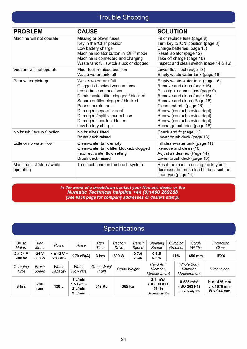
PROBLEM CAUSE SOLUTIONMachine will not operate Missing or blown fuses
Key in the ‘OFF’ positionLow battery chargeMachine isolator button in ‘OFF’ modeMachine is connected and chargingWaste tank full switch stuck or clogged
Fit or replace fuse (page 8)Turn key to ‘ON’ position (page 8)Charge batteries (page 18)Reset isolator (page 12)Take off charge (page 18)Inspect and clean switch (page 14 & 16)
Vacuum will not operate Floor tool in raised position Waste water tank full
Lower floor-tool (page 13)Empty waste water tank (page 16)
Poor water pick-up Waste-water tank fullClogged / blocked vacuum hoseLoose hose connections Debris basket filter clogged / blockedSeparator filter clogged / blockedPoor separator sealDamaged separator sealDamaged / split vacuum hoseDamaged floor-tool bladesLow battery charge
Empty waste-water tank (page 16)Remove and clean (page 16)Push tight connections (page 9)Remove and clean (page 16)Remove and clean (Page 16)Clean and refit (page 16)Renew (contact service dept)Renew (contact service dept) Renew (contact service dept)Recharge batteries (page 18)
No brush / scrub function No brushes fittedBrush deck raised
Check and fit (page 11)Lower brush deck (page 13)
Little or no water flow Clean-water tank emptyClean-water tank filter blocked/ cloggedIncorrect water flow settingBrush deck raised
Fill clean-water tank (page 11)Remove and clean (16)Adjust as desired (Page 14)Lower brush deck (page 13)
Machine just ‘stops’ while operating
Too much load on the brush system Reset the machine using the key and decrease the brush load to best suit the floor type (page 14)
Trouble Shooting
In the event of a breakdown contact your Numatic dealer or theNumatic Technical helpline +44 (0)1460 269268
(See back page for company addresses or dealers stamp)
Specifications
ChargingTime
BrushSpeed
WaterCapacity
WaterFlow rate
Gross Weigt(Full) Gross Weight
Hand ArmVibration
Measurement
Whole BodyVibration
MeasurementDimensions
8 hrs 200rpm 120 L
1 L/min1.5 L/min2 L/min3 L/min
549 Kg 365 Kg
2.1 m/s2
(BS EN ISO 5349)
Uncertainty 1%
0.525 m/s2
(ISO 2631-1)Uncertainty 1%
H x 1425 mmL x 1676 mmW x 944 mm
BrushMotors
VacMotor Power Noise Run
TimeTraction
DriveTransitSpeed
CleaningSpeed
ClimbingGradient
ScrubWidths
Protection Class
2 x 24 V400 W
24 V600 W
4 x 12 V = 200 Ahr ≤ 70 dB(A) 3 hrs 600 W 0-7.0
km/h0-3.5 km/h 11% 650 mm IPX4
25
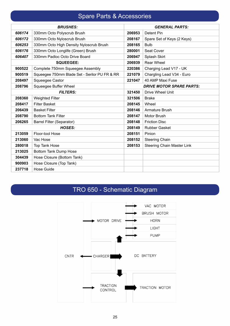
Spare Parts & AccessoriesBRUSHES: GENERAL PARTS:
606174 330mm Octo Polyscrub Brush 206953 Detent Pin606172 330mm Octo Nyloscrub Brush 208167 Spare Set of Keys (2 Keys)606253 330mm Octo High Density Nyloscrub Brush 208165 Bulb606176 330mm Octo Longlife (Green) Brush 280001 Seat Cover606407 330mm Padloc Octo Drive Board 206947 Splash Skirt
SQUEEGEE: 206939 Rear Wheel900522 Complete 750mm Squeegee Assembly 220386 Charging Lead V17 - UK900519 Squeegee 750mm Blade Set - Serilor PU FR & RR 221079 Chargling Lead V34 - Euro208497 Squeegee Castor 221047 40 AMP Maxi Fuse208796 Squeegee Buffer Wheel DRIVE MOTOR SPARE PARTS:
FILTERS: 321450 Drive Wheel Unit208360 Weighted Filter 321506 Brake208417 Filter Basket 208145 Wheel206439 Basket Filter 208146 Armature Brush208790 Bottom Tank Filter 208147 Motor Brush206265 Barrel Filter (Separator) 208148 Friction Disc
HOSES: 208149 Rubber Gasket213059 Floor-tool Hose 208151 Pinion213060 Vac Hose 208152 Steering Chain280018 Top Tank Hose 208153 Steering Chain Master Link213025 Bottom Tank Dump Hose304439 Hose Closure (Bottom Tank)900903 Hose Closure (Top Tank)237718 Hose Guide
TRO 650 - Schematic Diagram
26
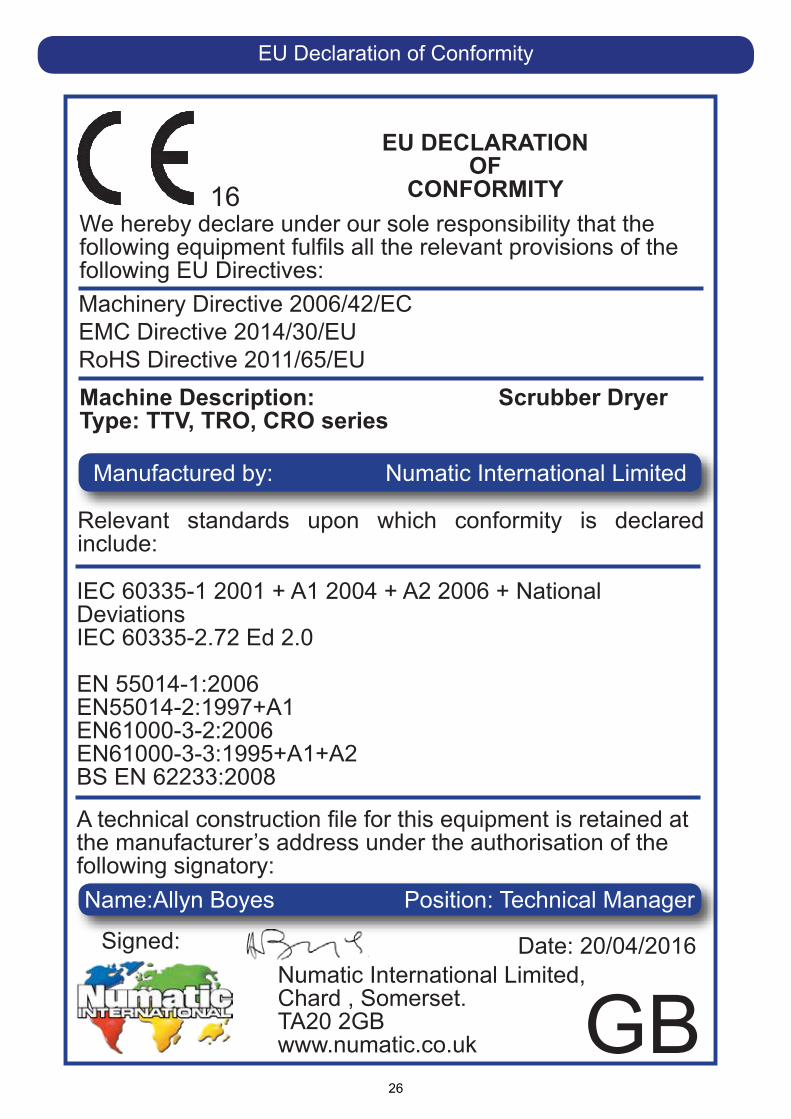
EU DECLARATION OF
CONFORMITYWe hereby declare under our sole responsibility that the following equipment fulfils all the relevant provisions of the following EU Directives:
Machine Description: Scrubber Dryer Type: TTV, TRO, CRO series
Relevant standards upon which conformity is declared include:
IEC 60335-1 2001 + A1 2004 + A2 2006 + National DeviationsIEC 60335-2.72 Ed 2.0
EN 55014-1:2006EN55014-2:1997+A1EN61000-3-2:2006EN61000-3-3:1995+A1+A2BS EN 62233:2008
A technical construction file for this equipment is retained at the manufacturer’s address under the authorisation of the following signatory:
Signed: Date: 20/04/2016Numatic International Limited, Chard , Somerset. TA20 2GB www.numatic.co.uk GB
16
Position: Technical ManagerName:Allyn Boyes
Manufactured by: Numatic International Limited
Machinery Directive 2006/42/ECEMC Directive 2014/30/EURoHS Directive 2011/65/EU
EU Declaration of Conformity

27

This machine has been packed with the following
Charging Lead
Fuses
Break Disengage Key
Hose Hook
38 / 32 mm Adaptor
Signed
TRO 650
244269 04/16 (A13)
Distributed by
Numatic International LimitedChard, Somerset
TA20 2GB ENGLAND.Telephone: 01460 68600 Fax: 01460 68458
www.numatic.co.ukSubject to change without prior notice.
www.numatic.co.uk © Numatic International Limited