OW L: FIRST STEPS TOW ARDS DESIGNING THE MECHANICAL · PDF fileSubmitted at the Workshop on...
12
Submitted at the Workshop on Extremely Large Telescopes, Bäckaskog, Sweden, June 1-2, 1999. OWL: FIRST STEPS TOWARDS DESIGNING THE MECHANICAL STRUCTURE E. Brunetto, F. Koch, M. Quattri European Southern Observatory Abstract The design, fabrication and assembly of the supporting structure of a 100-m class telescope is one of the major challenges of the OWL project. The structure must provide sufficient bandpass for the motion control system as well as the required tracking accuracy and dimensional stability under varying thermal and wind loads. The achievable limits of structural eigen-frequencies impose that image stabilisation be implemented downstream in the optical train. We elaborate on different approaches and preliminary solutions, discuss the option of a wind screen to allowing protection but without preventing flushing of local air, the use of damping systems to reduce vibration amplitudes, as well as use of advanced materials. Last but not least, particular attention is paid to costs. Guidelines are set to minimise fabrication, transport, handling, integration and maintenance efforts. 1. Introduction The mechanical structure shall be seen as a “skeleton”, which supports all the sub-systems of the telescope. The demonstration of its feasibility is therefore one of the major steps to be performed at the very beginning of the project. We include no speculations on future technological developments which could lead to unknown risks or budget increases. This approach can be summarised in the following question: Can we build a rotating support structure for a 100-m reflecting optical system today? The first step to answer this question is to detect, define and quantify the parameters (problems) which are related to the project. Some of these parameters are already well defined and they can be easily quantified. These can be for instance: • Constrains (e.g.: Optical design) • Requirements (e.g. Sky coverage) • Analogies, extrapolations and conjectures, coming from previous experiences in telescope construction. Other parameters are hidden or not clearly defined. Nevertheless they cannot be neglected because in most cases they reflect the unwritten know how of people who have gained expertise in this specific field over many years of work. Therefore, bad feeling, worries and concerns must also be quantified. Once the basic parameters have been collected, we are able to proceed to the second step, namely the classification of those parameters. Now the classification methodologies can be various (e.g. budget, criticality, chronological, disciplines, etc.) and all can work well. We have chosen to classify the parameters by domains. This means that for each parameter we have to find out where and when they appear and how they can influence the design. Finding domains for each parameter is a way to assessing and controlling their impact on the project. The third step is rather straightforward; we have to define a strategy that can cope with the problem. More clearly formulated is “What to do?”. Once “what to do” has been defined and agreed, comes the fourth step, the most awkward and less forgiving: “How to do it?”. This means defining a hardware solution to solve the problem.
Transcript of OW L: FIRST STEPS TOW ARDS DESIGNING THE MECHANICAL · PDF fileSubmitted at the Workshop on...
Submitted at the Workshop on Extremely Large Telescopes, Bäckaskog, Sweden, June 1-2, 1999.
OWL: FIRST STEPS TOWARDS DESIGNINGTHE MECHANICAL STRUCTURE
E. Brunetto, F. Koch, M. Quattri
European Southern Observatory
AbstractThe design, fabrication and assembly of the supporting structure of a 100-m class telescope is one of the majorchallenges of the OWL project. The structure must provide sufficient bandpass for the motion control system aswell as the required tracking accuracy and dimensional stabil ity under varying thermal and wind loads. Theachievable limits of structural eigen-frequencies impose that image stabil isation be implemented downstream inthe optical train. We elaborate on different approaches and preliminary solutions, discuss the option of a windscreen to allowing protection but without preventing flushing of local air, the use of damping systems to reducevibration amplitudes, as well as use of advanced materials. Last but not least, particular attention is paid to costs.Guidelines are set to minimise fabrication, transport, handling, integration and maintenance efforts.
1. Introduction
The mechanical structure shall be seen as a “skeleton” , which supports all the sub-systems of the telescope. The demonstrationof its feasibili ty is therefore one of the major steps to be performed at the very beginning of the project. We include nospeculations on future technological developments which could lead to unknown risks or budget increases.
This approach can be summarised in the following question:
Can we build a rotating support structure for a 100-m reflecting optical system today?
The first step to answer this question is to detect, define and quantify the parameters (problems) which are related to theproject. Some of these parameters are already well defined and they can be easily quantified. These can be for instance:
• Constrains (e.g.: Optical design)
• Requirements (e.g. Sky coverage)
• Analogies, extrapolations and conjectures, coming from previous experiences in telescope construction.
Other parameters are hidden or not clearly defined. Nevertheless they cannot be neglected because in most cases they reflect theunwritten know how of people who have gained expertise in this specific field over many years of work.
Therefore, bad feeling, worries and concerns must also be quantified.
Once the basic parameters have been collected, we are able to proceed to the second step, namely the classification of thoseparameters. Now the classification methodologies can be various (e.g. budget, criticali ty, chronological, disciplines, etc.) and allcan work well . We have chosen to classify the parameters by domains. This means that for each parameter we have to find outwhere and when they appear and how they can influence the design. Finding domains for each parameter is a way to assessingand controlli ng their impact on the project.
The third step is rather straightforward; we have to define a strategy that can cope with the problem. More clearly formulated is“What to do?” .
Once “what to do” has been defined and agreed, comes the fourth step, the most awkward and less forgiving: “How to do it?” .This means defining a hardware solution to solve the problem.
Submitted at the Workshop on Extremely Large Telescopes, Bäckaskog, Sweden, June 1-2, 1999.
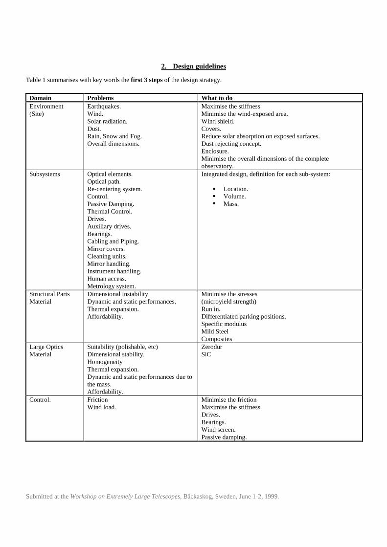
2. Design guidelines
Table 1 summarises with key words the first 3 steps of the design strategy.
Domain Problems What to doEnvironment(Site)
Earthquakes.Wind.Solar radiation.Dust.Rain, Snow and Fog.Overall dimensions.
Maximise the stiffnessMinimise the wind-exposed area.Wind shield.Covers.Reduce solar absorption on exposed surfaces.Dust rejecting concept.Enclosure.Minimise the overall dimensions of the completeobservatory.
Subsystems Optical elements.Optical path.Re-centering system.Control.Passive Damping.Thermal Control.Drives.Auxili ary drives.Bearings.Cabling and Piping.Mirror covers.Cleaning units.Mirror handling.Instrument handling.Human access.Metrology system.
Integrated design, definition for each sub-system:
� Location.� Volume.� Mass.
Structural PartsMaterial
Dimensional instabili tyDynamic and static performances.Thermal expansion.Affordabili ty.
Minimise the stresses(microyield strength)Run in.Differentiated parking positions.Specific modulusMild SteelComposites
Large OpticsMaterial
Suitabil ity (polishable, etc)Dimensional stabil ity.HomogeneityThermal expansion.Dynamic and static performances due tothe mass.Affordabili ty.
ZerodurSiC
Control. FrictionWind load.
Minimise the frictionMaximise the stiffness.Drives.Bearings.Wind screen.Passive damping.
Submitted at the Workshop on Extremely Large Telescopes, Bäckaskog, Sweden, June 1-2, 1999.
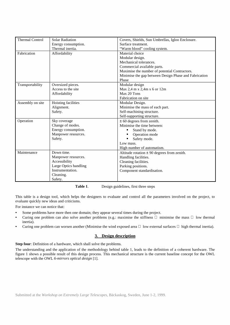
Thermal Control Solar RadiationEnergy consumption.Thermal inertia.
Covers, Shields, Sun Umbrellas, Igloo Enclosure.Surface treatment.“Warm blood” cooling system.
Fabrication Affordabili ty Material choiceModular design.Mechanical tolerances.Commercial available parts.Maximise the number of potential Contractors.Minimise the gap between Design Phase and FabricationPhase
Transportabilit y Oversized pieces.Access to the siteAffordabili ty
Modular designMax 2,4 m x 2,4m x 6 or 12mMax 20 TonsFabrication on site
Assembly on site Hoisting faciliti esAlignment.Safety.
Modular Design.Minimise the mass of each part.Self-machining structure.Self-supporting structure.
Operation Sky coverageChange of modes.Energy consumption.Manpower resources.Safety.
± 60 degrees from zenith.Minimise the time between:
� Stand by mode.� Operation mode� Safety mode.
Low mass.High number of automatism.
Maintenance Down time.Manpower resources.Accessibili tyLarge Optics handlingInstrumentation.Cleaning.Safety.
Altitude rotation ± 90 degrees from zenith.Handling facili ties.Cleaning faciliti es.Parking positions.Component standardisation.
Table 1. Design guidelines, first three steps
This table is a design tool, which helps the designers to evaluate and control all the parameters involved on the project, toevaluate quickly new ideas and criticisms.
For instance we can notice that:
• Some problems have more then one domain; they appear several times during the project.• Curing one problem can also solve another problems (e.g.: maximise the stiffness ⇒ minimise the mass ⇒ low thermal
inertia).• Curing one problem can worsen another (Minimise the wind exposed area ⇒ low external surfaces ⇒ high thermal inertia).
3. Design description
Step four: Definition of a hardware, which shall solve the problems.
The understanding and the application of the methodology behind table 1, leads to the definition of a coherent hardware. Thefigure 1 shows a possible result of this design process. This mechanical structure is the current baseline concept for the OWLtelescope with the OWL 6-mirrors optical design [1].

Submitted at the Workshop on Extremely Large Telescopes, Bäckaskog, Sweden, June 1-2, 1999.
Figure 1. Baseline concept
Besides the most conventional solution in telescope design (traditional alt-azimuth mount) which are widely accepted andrealised, this mechanical structure also introduces some innovative concepts, including:
� An azimuth ring instead of a conventional fork to minimise the distance between the tube and the ground. The azimuth ring
is embedded into the ground, thus increasing the stiffness.�
An iso-static configuration is foreseen in parking position. Thus will the structure be allowed to expand freely duringdaytime.
� A hyper-static configuration is foreseen during operation. Thus the mechanical performance will reach an optimal stiffness
during observation.�
Dust rejecting concept. Pollution of the optics is a major concern. Therefore the accumulation of dirt on the mechanicalstructure shall be minimised, rounding edges and corners and no flat surfaces. Thus the cleaning of the external surfaceswill be facilit ated.
� Dimensional instabili ty due to residual stresses can be minimised with a running in period prior to the integration of the
optical components. Alternate parking positions can minimise the asymmetrical creeping of the structure.
Submitted at the Workshop on Extremely Large Telescopes, Bäckaskog, Sweden, June 1-2, 1999.
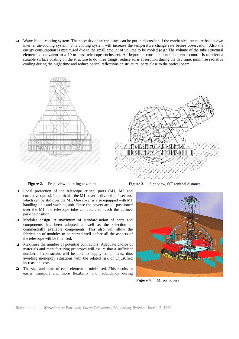
� Warm blood-cooling system. The necessity of an enclosure can be put in discussion if the mechanical structure has its own
internal air-cooling system. This cooling system will i ncrease the temperature change rate before observation. Also theenergy consumption is minimised due to the small amount of volume to be cooled (e.g.: The volume of the tube structuralelement is equivalent to a 10-m class telescope enclosure). An important consideration for thermal control is to select asuitable surface coating on the structure to do three things: reduce solar absorption during the day time, minimise radiativecooling during the night time and reduce optical reflections on structural parts close to the optical beam.
Figure 2. Front view, pointing at zenith. Figure 3. Side view, 60o zenithal distance.�
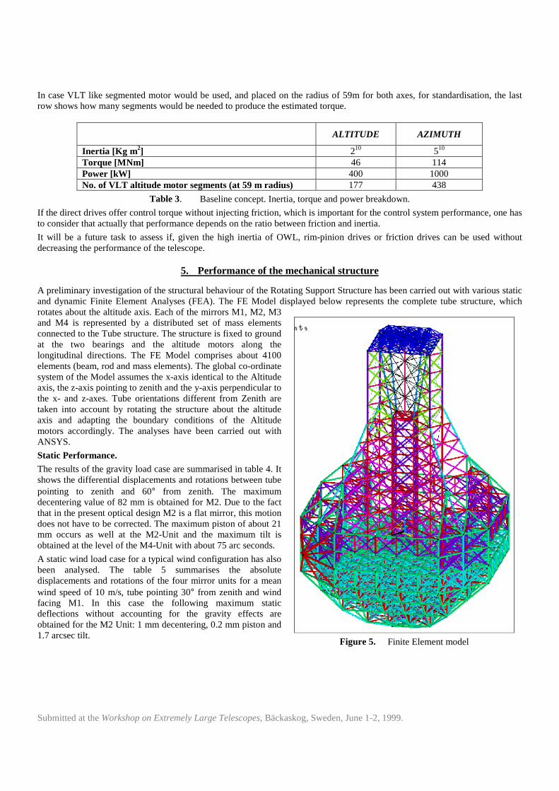
Local protection of the telescope critical parts (M1, M2 andcorrective optics). In particular the M1 cover is divided in 4 sectors,which can be slid over the M1. One cover is also equipped with M1handling unit and washing unit. Once the covers are all positionedover the M1, the telescope tube can rotate to reach the definedparking position.
� Modular design. A maximum of standardisation of parts and
components has been adopted as well as the selection ofcommercially available components. This also will allow thefabrication of modules to be started well before all the aspects ofthe telescope will be finalised.
� Maximise the number of potential contractors. Adequate choice of
materials and manufacturing processes will assure that a suff icientnumber of contractors will be able to supply components, thusavoiding monopoly situations with the related risk of unjustifiedincrease in costs
� The size and mass of each element is minimised. This results in
easier transport and more flexibili ty and redundancy during
Figure 4. Mirror covers

Submitted at the Workshop on Extremely Large Telescopes, Bäckaskog, Sweden, June 1-2, 1999.
installation (e.g.: several smallcranes instead of one largecrane, etc).
� Fabrication on site of part of the
structural elements can alsoreduce the transport costs. Sincethis is related to manufacturingprocess typical of eachmanufacturing company, itcannot be introduced in to thedesign at this early stage
� Self-machining structure. The
journal of the bearing will havethe final machining on site,using the structure itself has alarge-scale machine tool.
� Self-supporting structure. The
structure is divided in floors,each floor serve as a stand forthe next floor during assembly.This technique will minimise theamount of scaffoldings and therisk associated to the installationof large elements.
� Rotation range of ± 90o from zenith facil itates installation and maintenance of the secondary mirror optics.
Subsystem Mass [tons]Tube Structure. 6500Primary mirror + cell . (Mirror area density 160 Kg / m2). 2000Secondary Mirror + cell . (Mirror area density 100 Kg / m2). 150Corrective optics + instrumentation. 150Azimuth Ring Structure. 8000Azimuth Track. 5000
Table 2. Baseline concept, mass breakdown.
4. Drives
In choosing the max. velocity and the acceleration to move OWL as 0.5o.s-1 and 0.1o.s-2 respectively, we have considered thefollowing parameters:
• Slewing time: with such a large inertia we specified this to be about 3 minutes to cover the altitude range of 90• and about12 minutes to make a complete revolution in azimuth).
• Induced centrifugal acceleration on the structure is of the order of 0.1g.
• Low dynamic range of tracking velocity to reach a good control. This is similar to the VLT, with maximum trackingvelocity equal to the slewing velocity).
• Low blind angle at azimuth of about 1• , as with the VLT.
In the table 3 the estimated torque and power for both altitude and azimuth axes are summarised.
Figure 4. Parking configuration.
Submitted at the Workshop on Extremely Large Telescopes, Bäckaskog, Sweden, June 1-2, 1999.
In case VLT like segmented motor would be used, and placed on the radius of 59m for both axes, for standardisation, the lastrow shows how many segments would be needed to produce the estimated torque.
ALTITUDE AZIMUTH
Inertia [Kg m2] 210 510
Torque [MNm] 46 114Power [kW] 400 1000No. of VLT altitude motor segments (at 59 m radius) 177 438
Table 3. Baseline concept. Inertia, torque and power breakdown.
If the direct drives offer control torque without injecting friction, which is important for the control system performance, one hasto consider that actually that performance depends on the ratio between friction and inertia.
It will be a future task to assess if, given the high inertia of OWL, rim-pinion drives or friction drives can be used withoutdecreasing the performance of the telescope.
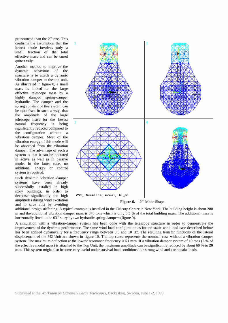
5. Performance of the mechanical structure
A preliminary investigation of the structural behaviour of the Rotating Support Structure has been carried out with various staticand dynamic Finite Element Analyses (FEA). The FE Model displayed below represents the complete tube structure, whichrotates about the alti tude axis. Each of the mirrors M1, M2, M3and M4 is represented by a distributed set of mass elementsconnected to the Tube structure. The structure is fixed to groundat the two bearings and the alti tude motors along thelongitudinal directions. The FE Model comprises about 4100elements (beam, rod and mass elements). The global co-ordinatesystem of the Model assumes the x-axis identical to the Altitudeaxis, the z-axis pointing to zenith and the y-axis perpendicular tothe x- and z-axes. Tube orientations different from Zenith aretaken into account by rotating the structure about the alti tudeaxis and adapting the boundary conditions of the Alti tudemotors accordingly. The analyses have been carried out withANSYS.
Static Performance.
The results of the gravity load case are summarised in table 4. Itshows the differential displacements and rotations between tubepointing to zenith and 60° from zenith. The maximumdecentering value of 82 mm is obtained for M2. Due to the factthat in the present optical design M2 is a flat mirror, this motiondoes not have to be corrected. The maximum piston of about 21mm occurs as well at the M2-Unit and the maximum tilt isobtained at the level of the M4-Unit with about 75 arc seconds.
A static wind load case for a typical wind configuration has alsobeen analysed. The table 5 summarises the absolutedisplacements and rotations of the four mirror units for a meanwind speed of 10 m/s, tube pointing 30° from zenith and windfacing M1. In this case the following maximum staticdeflections without accounting for the gravity effects areobtained for the M2 Unit: 1 mm decentering, 0.2 mm piston and1.7 arcsec tilt .
Figure 5. Finite Element model

Submitted at the Workshop on Extremely Large Telescopes, Bäckaskog, Sweden, June 1-2, 1999.
Dynamic Performance.
Based on the FE model mentioned before, the dynamic performance of the structure has been investigated with a ModalAnalysis and several Harmonic Response Analyses.
The results of the Modal Analysis are listed in the table 6 in terms of mode numbers, eigen frequencies, corresponding effectivemass distribution and mode shape descriptions. In this configuration the motors are assumed to be locked and the tube ispointing to zenith. Except the first mode, only those modes are indicated in the table that might have an influence to the opticalperformance of the telescope structure.
Location Displacement [mm] Rotation [arcsec] Location Displacement [mm] Rotation [arcsec]
Decentering Piston Tilt Decentering Piston Tilt
M1 17.3 11.2 23.6 M1 0.1 0.1 0.4
M2 82.0 20.6 65.5 M2 1.0 0.2 1.7
M3 16.8 14.7 19.0 M3 0.2 0.1 1.1
M4 32.3 17.8 74.8 M4 0.6 0.2 1.6
Table 4. Gravity Loading (differential deflectionbetween Zenith and 60° from Zenith)
Table 5. Static Wind Loading (absolute deflection for10 m/s at 30° from Zenith)
The 1st mode at 1.1 Hz is a pure rotational modeabout the vertical optical axis and does notinfluence the optical performance of theTelescope. The first important mode for theoptical performance occurs at 1.35 Hz. Asshown in the mode shape plot (figure 6), itrepresents the lateral shear mode of the TopTower along the global y-axis. The 3rd mode at1.4 Hz is again a lateral shear mode along theglobal x-axis. Since the first eight modes areeither rotational modes about the vertical z-axisor contain only a relatively small fraction ofeffective mass (only part of the top tower isaffected by the vibration), their naturalfrequency can easily be increased by changingthe design and/or using composite material onlyfor the Top Tower part and/or using Sili conCarbide secondary mirrors. The first globalmode of the structure occurs at 2.43 Hz. In thiscase also the intermediate structure is affectedby the vibration. The stiffness and compactnessof the structure in vertical z-direction isconfirmed by the fact, that only one mode at 3.6Hz contains almost 90 % of the total mass.
The influence of the motor torque to the lateraldisplacement of the M2 unit has also beensimulated. In this case the tube is pointing tozenith and the rotor is free about the alti tude
axis. A harmonic unit load representing the motor torque has been applied to the structure. The transfer function (figure 7)shows the dynamic response displacement of the M2 unit along the global y-axis to the motor torque. The 1st peak is much less
Mode Frequency Effective Mass [%] Mode Shape
[Hz] X Y Z
1 1.131 - - - Top Tower, rotation z
2 1.354 - 8.1 - Top Tower, lateral y
3 1.400 5.6 - - Top Tower, lateral x
5 1.748 - 6.1 - Top Tower, lateral y
6 1.808 7.4 - - Top Tower, lateral x
9 2.429 10.9 - - Intermediate, lateral x
11 2.500 - 4.7 - Intermediate, lateral y
13 2.849 11.9 - - Intermediate, lateral x
14 2.962 - 7.0 - Intermediate, lateral y
17 3.208 0.9 - - Top Tower, lateral x
18 3.212 - 0.2 - Top Tower, lateral y
20 3.289 17.5 - - Inter + Top, lateral x
22 3.396 - 33.0 - Inter + Top, lateral y
24 3.560 - - 89.3 All , vertical z
Cumulative Mass: 54.2 59.2 89.3 At mode 24 (3.56 Hz)
Cumulative Mass: 93.6 94.0 93.5 At mode 62 (6.13 Hz)
Cumulative Mass: 96.3 95.8 96.6 At mode 150 (12.7 Hz)
Table 6. Dynamic performance, Eigenfrequencies (locked rotor,Zenith, total Mass: 8744 tons)
Submitted at the Workshop on Extremely Large Telescopes, Bäckaskog, Sweden, June 1-2, 1999.
pronounced than the 2nd one. Thisconfirms the assumption that thelowest mode involves only asmall fraction of the totaleffective mass and can be curedquite easily.
Another method to improve thedynamic behaviour of thestructure is to attach a dynamicvibration damper to the top unit.As il lustrated in figure 8, a smallmass is linked to the largeeffective telescope mass by ahighly damped spring-damperhydraulic. The damper and thespring constant of this system canbe optimised in such a way, thatthe amplitude of the largetelescope mass for the lowestnatural frequency is beingsignificantly reduced compared tothe configuration without avibration damper. Most of thevibration energy of this mode willbe absorbed from the vibrationdamper. The advantage of such asystem is that it can be operatedin active as well as in passivemode. In the latter case, noadditional energy or controlsystem is required.
Such dynamic vibration dampersystems have been alreadysuccessfully installed in highstory buildings, in order todecrease significantly the highampli tudes during wind excitationand to save cost by avoidingadditional design stiffening. A typical example is installed in the Citicorp Center in New York. The building height is about 280m and the additional vibration damper mass is 370 tons which is only 0.5 % of the total building mass. The additional mass ishorizontally fixed to the 63rd story by two hydraulic spring-dampers (figure 9).
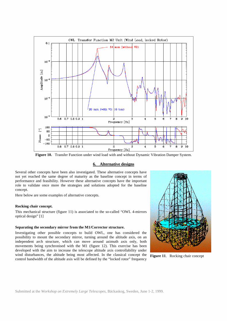
A simulation with a vibration-damper system has been done with the telescope structure in order to demonstrate theimprovement of the dynamic performance. The same wind load configuration as for the static wind load case described beforehas been applied dynamically for a frequency range between 0.5 and 10 Hz. The resulting transfer functions of the lateraldisplacement of the M2 Unit are shown in figure 10. The top curve represents the nominal case without a vibration dampersystem. The maximum deflection at the lowest resonance frequency is 51 mm. If a vibration damper system of 10 tons (2 % ofthe effective modal mass) is attached to the Top Unit, the maximum amplitude can be significantly reduced by about 60 % to 20mm. This system might also become very useful under survival load conditions like strong wind and earthquake loads.
Figure 6. 2nd Mode Shape

Submitted at the Workshop on Extremely Large Telescopes, Bäckaskog, Sweden, June 1-2, 1999.
Figure 7. Transfer function M2 unit (Motor torque, free rotor).
Figure 8. Dynamic vibration damper Figure 9 Example: Citicorp Center, New York. Height 279 m,additional Mass: 370 tons (0.5 % of building)
Submitted at the Workshop on Extremely Large Telescopes, Bäckaskog, Sweden, June 1-2, 1999.
Figure 10. Transfer Function under wind load with and without Dynamic Vibration Damper System.
6. Alternative designs
Several other concepts have been also investigated. These alternative concepts havenot yet reached the same degree of maturity as the baseline concept in terms ofperformance and feasibility. However these alternative concepts have the importantrole to validate once more the strategies and solutions adopted for the baselineconcept.
Here below are some examples of alternative concepts.
Rocking chair concept.
This mechanical structure (figure 11) is associated to the so-called “OWL 4-mirrorsoptical design” [1]
Separating the secondary mirror from the M1/Corrector structure.
Investigating other possible concepts to build OWL, one has considered thepossibili ty to mount the secondary mirror, turning around the altitude axis, on anindependent arch structure, which can move around azimuth axis only, bothmovements being synchronised with the M1 (figure 12). This exercise has beendeveloped with the aim to increase the telescope altitude axis controllabili ty underwind disturbances, the alti tude being most affected. In the classical concept thecontrol bandwidth of the alti tude axis will be defined by the “ locked rotor” frequency
Figure 11. Rocking chair concept

Submitted at the Workshop on Extremely Large Telescopes, Bäckaskog, Sweden, June 1-2, 1999.
which is represented in the baseline concept by the frequency of the M2 tower. In the case outlined here, the control bandwidthof the position of M2 will be defined by the secondary mirror structure mass and the stiffness of the motor mounting, which canbe designed for relatively high values (eigen frequency in the order of 5Hz). To synchronise the motion between the two parts,commercial transponders can be used, which deliver positioning accuracy within some tenths of a millimetre. The power of themotors to control the motion of M2 structure it is estimated in about 30 kW, to move at 3 Hz by a range of about 50mm.
Figure 12. Arch concept
7. Conclusions
We can conclude that the rotating support structure of a 100-m optical system can be build as per today using conventional, wellunderstood and largely realised technology. Moreover, the conservative approach of using optical element made of Zerodur inthe performance analyses put OWL on the safe side. That means that we do not have to speculate on future developmentconcerning lightweight optical materials. Also the choice of commercial available components is an indication that themechanical structure will not represent a technological risk in the OWL project and the foreseen budget can be respected.
8. References
[1] P. Dierickx, J. Beletic, B. Delabre, M. Ferrari, R. Gilmozzi, N. Hubin, The optics of the owl 100-m adaptive telescope, thisconference.