Overview of Concentrating Solar Power for Electricity ...501936/FULLTEXT01.pdf · Overview of...
93
EKV 23/09 Overview of Concentrating Solar Power for Electricity Production, with Emphasis on Steam Turbine Aspects ANNELI CARLQVIST STOCKHOLM 9-Nov-09 Division of Heat and Power Kungliga Tekniska högskolan 100 44 STOCKHOLM
-
Upload
hoangxuyen -
Category
Documents
-
view
214 -
download
0
Transcript of Overview of Concentrating Solar Power for Electricity ...501936/FULLTEXT01.pdf · Overview of...

EKV 23/09
Overview of Concentrating Solar Power for Electricity Production, with Emphasis on Steam Turbine
Aspects
ANNELI CARLQVIST
STOCKHOLM 9-Nov-09
Division of Heat and Power Kungliga Tekniska högskolan 100 44 STOCKHOLM

Division of Energy Technology Chair of Heat and Power Technology Professor: Torsten H. Fransson
Title Overview of Concentrating Solar Power for Electricity Production, with Emphasis on Steam Turbine Aspects Author Anneli Carlqvist Report No EKV .... Project title Turbopower (T6373) Pages Drawings ..... Supervisor KTH: Prof. T. Fransson Assoc. Prof. A. Martin
Date 09-11-09 References .....
Overall responsible at KTH: Prof. T. Fransson Approved at KTH by: Signature: Overall responsible at industry: - Markus Jöcker Industrial partners: - Siemens, Energimyndigheten, VAC Approved by industrial partners: - Signature: - Approved for Restricted, to distribution list below:
X Open: Abstract The European Union targets a reduction of greenhouse gas emissions by 20% of renewable energy sources in the EU energy mix by 2020. New generations of technologies have to be developed through breakthroughs in research if the vision is to be met. The deregulation of the electric power market has opened the market to investors seeking profits and growth via the installation of additional capacity. This literature review report is a introductory step towards a more detailed and targeted work for a system concept evaluation, analysis and optimization of solar turbines in concentrating solar thermal power production. Concentrating Solar Power (CSP) has grown in recent years to be the largest bulk producer of solar electricity in the world and every square meter of a CSP field that produces 400 - 500 kWh of electricity per year, saves 0,45 ton of CO2 and contributes to a 0,1 ton reduction of fossil fuels use annually. The CSP is divided in two concepts and three main technologies: Linear– and point focus concept; Parabolic trough -, Power Tower- and dish- Stirling engine technologies. Whereas the Power Tower technology has the best gross efficiency, the parabolic trough has the advantage to be the most mature technology, being in grid connected power plant operation for at least two decades. Dish-Stirling engine systems have the highest net efficiency but suffer from the sensibility to insolation fluctuations and lack of storage. There are various thermal storage medias and storage concepts to help achieving the best thermal characteristics for charging and discharging to the CSP technology in question. The dispatch time ranges from 0,5 hour for maintenance and service up to 16-24 hours thermal energy dispatchability. The most recently commercialized thermal storage media is phase change material, i.e. salt mixtures with good thermal characteristics. Research for other kind of media suitable for CSP-technology is performed continuously. The operation modes of a CSP plant depends on the choice of electricity production; dispatch electricity during day-time hours or prolonging the electricity production beyond sunset. The Organic Rankine Cycle (ORC) is another CSP concept using organic thermal fluid instead of steam to the turbine, at a lower temperature and pressure range. The power output is of range 1–5 MW for electricity production. The ORC ability to use simpler components and the possibility to deployment in rural areas as well as on limited space in urban areas, make it more economical feasible. The organic fluid is for example n-pentane and toluene. The net efficiency for ORC-plants has been proven to achieve 30% under optimal conditions, comparing to the Rankine cycle practical efficiency of 36-40 %. The experiences from CSP plant operation have raised a demand for improvement of the steam turbine’s work performance. The steam turbine has until recently being designed to be in continuous work. The steam turbine operating in solar thermal plants should have the capability to start up directly and go from idle to rated condition in a matter of minutes. The CSP-plant start-ups per year is higher where the cycling thermal stresses can cause material fatigue leading to shorter life time. Efficient collector, storage design and optimal turbine operation should reduce the number of start-ups and shutdowns per year and the transient loads on the steam turbine.
Distribution list
Prof. T. Fransson Assoc. Prof A.Martin Dr. P. Almqvist HPT archive Markus Jöcker
HPT HPT HPT HPT Siemens
1 1 1 1 1
Overview of Concentrating Solar Power for Electricity Production, with Emphasis on Steam Turbine Aspects
TABLE OF CONTENTS
1 Introduction ......................................................................................................... 9
2 Electric Production from csp ................................................................................ 9
2.1 Global Market Initiatives .............................................................................. 10
2.2 Key-Technology Factors .............................................................................. 11
2.3 Steam Turbine ............................................................................................. 13
3 aim and Scope .................................................................................................. 13
4 Methodology and report structure ...................................................................... 14
5 Solar Concentrating Plants ................................................................................ 15
5.1 Parabolic Trough Collectors ........................................................................ 16
5.1.1 Primary circuit -Thermal oil ................................................................... 18
5.1.2 Primary circuit thermal oil – Molten salt thermal energy storage ........... 20
5.1.3 Direct Steam Generation ...................................................................... 21
5.2 Linear Fresnel Reflector - LFR .................................................................... 24
5.2.1 Compact Linear Fresnel Reflector - CLFR ............................................ 25
5.3 Power Tower - Central Receiver Plant ........................................................ 27
5.3.1 Power Tower with direct steam generation .......................................... 30
5.3.2 Power Tower with molten salt thermal media........................................ 31
5.3.3 Power Tower – Atmospheric air ............................................................ 33
5.3.4 Heliostat field layout .............................................................................. 34
5.3.5 Pit Power Tower .................................................................................... 35
5.3.6 Multi Tower Solar Array ........................................................................ 36
5.4 Circular Parabolic Solar Concentrator – Dish-Stirling .................................. 36
5.4.1 Dish-Stirling System Characteristics, and Comparison to Other
Technologies ..................................................................................................... 37
5.4.2 Dish Concentrator ................................................................................. 38
1

Overview of Concentrating Solar Power for Electricity Production, with Emphasis on Steam Turbine Aspects
5.4.3 Dish-Stirling receivers ........................................................................... 40
5.4.4 Receiver Losses ................................................................................... 42
6 Thermal Storage for CSP .................................................................................. 43
6.1 Sensible heat and latent heat TES ............................................................. 44
6.1.1 Sensible Heat TES - Media .................................................................. 45
6.1.2 Latent heat TES – PCM’s ..................................................................... 47
6.2 Chemical Energy Storage (CES) ................................................................. 50
6.3 Mechanical Energy Storage (MES) ............................................................. 52
6.4 Thermal Energy Storage concepts (TES) .................................................... 52
7 power block features of Csp plants ................................................................... 57
7.1 Steam turbine .............................................................................................. 58
7.2 Dynamic Operation of Steam Turbine in CSP Plants .................................. 62
7.3 Organic Rankine Cycle Plant ....................................................................... 67
7.3.1 Cooling Water Requirements ................................................................ 70
8 Conluding remarks ............................................................................................ 71
9 Table of selected current and projected CSTEPP ............................................. 71
10 Bibliography .................................................................................................... 74
APPENDIX 1. Concentrating Factor – C 82
2. CSP Power Plants 85
3. TES – Media 89
2

Overview of Concentrating Solar Power for Electricity Production, with Emphasis on Steam Turbine Aspects
LIST OF FIGURES
Figure 1. Example of a CSTEPP with parabolic trough and 2-tank molten salt passive
indirect TES (SolarMillenium). .................................................................................. 15
Figure 2. a) A semi-parabolic collector. b) A compound parabolic reflector ............ 16
Figure 3. a) Parabolic trough, Solnova, Seville, Spain, (Abengoa Solar, 2008). ....... 17
Figure 4. Solnova-1 Seville, Spain, Abengoa Solar (Abengoa Solar). .................... 19
Figure 5. Construction site of AndaSol 1-3 April 2008 (SolarMillenium) ................... 21
Figure 6. Recirculation in a DSG parabolic trough field with superheating.
(Reproduced from ..................................................................................................... 21
Figure 7. Water injection in the superheating stage, DSG. (Reproduced from: Zarza,
et al., 2005) ............................................................................................................... 22
Figure 8. Saturated steam DSG parabolic trough plant (Zarza, et al., 2006). ........... 23
Figure 9. Example of a Fresnel reflector. .................................................................. 24
Figure 10. An example of a LFR 1st and 2nd reflectors and absorber design –
Solarmundo Fresnel Collector (Bockenamp, et al., 2003). ....................................... 25
Figure 11. Ausra CLFR at Lidell Power Station (EPRI, 2008). .................................. 26
Figure 12. CLFR Power plant, Ausra concept. (Ausra, 2007) ................................... 26
Figure 13. PS20 and PS10 behind, Plataforma de solar, Spain. (Abengoa Solar,
2009) ........................................................................................................................ 28
Figure 14. Heliostat. (BrightSource, 2009) ............................................................... 28
Figure 15. Example of a DSG Power Tower with a saturated steam receiver. (Solúcar
Solar S.A, 2006) ....................................................................................................... 30
Figure 16. Example of a molten salt Power Tower with a molten salt receiver. ........ 32
Figure 17. Example of Atmospheric air Power Tower – volumetric air cooler. (Pietz-
Paal et al., 2005) ...................................................................................................... 33
Figure 18. eSolar 46 MW Power tower concept. (eSolar, 2008) ............................... 34
Figure 19. An Animated picture of the Luz II – concept, a 33 MWe solar cluster.
(www.news.cnet.com) .............................................................................................. 35
Figure 20. Binham Canyon Mine, US and an animated picture of a theoretical PPT
design (DiBella, et al., 2009). .................................................................................... 36
3

Overview of Concentrating Solar Power for Electricity Production, with Emphasis on Steam Turbine Aspects
Figure 21. Examples of dish-Stirling concentrators, a) Science Application
International Corporation, b) Western Governors’ Association (owned by SES 2005)
................................................................................................................................. 37
Figure 22. Australian National University dish-Stirling concentrator. ........................ 38
Figure 23. Examples of dish-Stirling concentrators. a) Stirling Engine System, b)
Schlaich Bergermann und Partner ............................................................................ 39
Figure 24. MDAC-receiver (Andraka, et al., 1994). ................................................... 41
Figure 25. Cummin/Thermacore heat pipe absorber. Capillary Wick structure
including arteries to distribute the liquid metal (Andraka, et al., 1994). ..................... 41
Figure 26. Example of a volumetric receiver. (Diver, Richard B., et al.) ................... 42
Figure 27. Thermal Energy Storage based on storage media. ................................. 44
Figure 28. Various PCM material/molten salts, thermal conductivity – Melting point
relation. (Hoshi, et al., 2004) ..................................................................................... 48
Figure 29. Chemical TES, Ammonia as media in a dish-sterling system. (ANU, 2008)
................................................................................................................................. 51
Figure 30. Thermal energy storage based on passive and active systems. ............. 53
Figure 31. PCM-cascade TES concept for parabolic trough CSP (reproduced from
Knutsson, 2008). ...................................................................................................... 55
Figure 32. Example of a Solar thermal steam power plant for electricity production
with no TES and fuel back-up. .................................................................................. 57
Figure 33. Example of Gland Sealing steam system. ............................................... 60
Figure 34. Annual direct Insolation period 2000 – 2008. (source: Abengoa Solar) ... 62
Figure 35. Diurnal operation of a CSP plant – TES storage, prolonged electricity
production. (source: FLAGSOL) ............................................................................... 63
Figure 36. Diurnal operation of CSP - plant. TES storage as intermediate stage.
(source Solar Millenium) ........................................................................................... 63
Figure 37. Diurnal operation DSG CSP-plant for month of January (Arza, et al.,
2004). ....................................................................................................................... 64
Figure 38. Diurnal operation DSG CSP-plant for month of June (Arza, et al., 2004). 65
Figure 39. Steam turbine diurnal operation in CSP. (source: Siemens Industrial
Turbomachinery AB) ................................................................................................. 66
Figure 40. ORC Tier-Cascade/Recuperator/Reheat steam turbine cycle with high-
and low ..................................................................................................................... 69
Figure 41. Schematic Diagram of Saguaro Solar Trough Plant Operation. .............. 69
4
Overview of Concentrating Solar Power for Electricity Production, with Emphasis on Steam Turbine Aspects
Appendix Figure 1. The solar point of view, the dilution of solar irradiation flux and the aperture
factor from a solar collector point of view, where it sees the solid angle of the
Hemisphere. 82
Figure 2. Solar irradiation onto a collector’s aperture and reciever 84
Figure 3. CSP plant for Direct superheated steam generation 86
5

Overview of Concentrating Solar Power for Electricity Production, with Emphasis on Steam Turbine Aspects
LIST OF TABLES Table 1. A comparison between different CSP technologies, 50 MWe, 3 hrs storage, reference systems, annual basis. ............................................................................. 12
Table 2. A selection of thermal oil for CSP primary circuit heat transfer fluid (Moens,
2004). ....................................................................................................................... 19
Table 3. Data comparison of selected dish Stirling systems, see previous pictures.
(Mancini, et al., 2003) ............................................................................................... 40
Table 4. PCM cascade salts used in TES for parabolic trough CSP. (Knutsson,
2008)) ....................................................................................................................... 56
Table 5. Water usage of different plants based on data from US Department of
Energy, (NREL 2006). .............................................................................................. 70
Table 6 a) Selected CSTEPP projects, operational and planned plants. ................. 72
Appendix Table 1. Solnova-plant, parabolic trough CSP, Seville, Spain. 85
Table 2. Solnova-plant, parabolic trough CSP Power cycle data, Seville, Spain.
85
Table 3. AndaSol 1-3, parabolic trough CSP, plant data, Spain. 85
Table 4. AndaSol 1-3, parabolic trough CSP, Power cycle data, Spain. 85
Table 5. DISS/INDITEP Superheated steam DSG parabolic trough CSP data.
86
Table 6. DISS/INDITEP Superheated steam DSG parabolic trough CSP, power cycle
data. 86
Table 7. DISS/INDITEP Saturated steam DSG parabolic trough solar plant 87
Table 8. DISS/INDITEP Saturated steam DSG parabolic trough solar plant. 87
Table 9. PS10-plant, Power Tower CSP, Seville, Spain. 87
Table 10. PS10-plant, Power Tower, Power cycle, Seville, Spain. 87
Table 11. Solar-Tres, SENER power Tower data, Spain. 88
Table 12. Solar-Tres, SENER power Tower data, Power cycle, Spain. 88
Table 13. Saguaro Organic Rankine Cycle, parabolic trough solar plant. 88
6

Overview of Concentrating Solar Power for Electricity Production, with Emphasis on Steam Turbine Aspects
Table 15. Thermal characteristics of TES liquid media. (Pilkington Solar Int., 2000)
89
Table 16. Thermal Characteristics of liquid salt mixtures. 89
Table 17 Thermal characteristics, TES – solid media. (Pilkington Solar Int., 2000)
90
Table 18. LHTS – Thermal characteristics of PCM salt mixtures. (Tamme R., 2003)
90
7

Overview of Concentrating Solar Power for Electricity Production, with Emphasis on Steam Turbine Aspects
ACRONYMS
ANU Australian National University APS Arizona Public Service Co. CAES Compressed Air Energy Storage CCP Combined Cycle Plant CLFR Central Linear Fresnel Reflector CR Concentrating Ratio CRS Central Receiver System CSP Concentrating Solar Power DIR Direct Illumination Receiver DISS DIrect Solar Steam DLR Deutsches Zentrum fϋr Luft- und Raumfahrt DNI Direct Normal Irradiation
DOE The U.S. Department of Energy Solar Energy Technologies Program
DSG Direct Steam Generation GMI Global Market Initiative HP High pressure IAP International Action Programme
INDITEP Integration of DIrect steam generation Technology for Electricity Production
IP Intermediate Pressure LP Low Pressure MES Mechanical Energy Storage MCPAM MoleCular PhAse change Material MCPCM Microencapsulated Phase Change Material MTSA Multi Tower Solar Array ORC Organic Rankine Cycle PCM Phase Change Material PSA Plataforma Solar de Almeria R&D Research and Development ST Steam Turbine RTR Reversible Thermo-Chemical Reactions TES Thermal Energy Storage
8

Overview of Concentrating Solar Power for Electricity Production, with Emphasis on Steam Turbine Aspects
1 INTRODUCTION
This literature review report is a introductory step towards a more detailed and
targeted work for a system concept evaluation, analysis and optimization of solar
turbines in concentrating solar thermal power production. Siemens Industrial
Turbomachinery AB, Sweden in collaboration with KTH are the main stakeholders for
the project “Steam Turbine Optimization for Solar Thermal Power Plant Operation”,
financed by Siemens and the Swedish Energy Agency. It is a part of a long term
industrial research effort in the field of thermal turbomachines and processes set with
the overriding goal to contribute to the transition into a more sustainable energy
society. Other interested parties within the field of sustainable development that
could be interested in the overview are universities, environmental organizations and
the solar thermal power industry. The overall aim of the report is to examine the
system and component details of present solar concentrating thermal electricity
power production plants.
2 ELECTRIC PRODUCTION FROM CSP
The European Union targets a reduction of greenhouse gas emissions by 20% and
aims for 20% of renewable energy sources in the EU energy mix by 2020 (EC, 2007).
It is stated in the European Strategic Energy Technology Plan (SET-PLAN) that in
order to meet the targets, it is necessary to lower the cost of clean energy and put
EU industry at the forefront of the rapidly growing low carbon technology sector .
Furthermore acknowledgement is given to the fact that new generations of
technologies have to be developed through breakthroughs in research if the vision to
meet a reduction in the EU greenhouse gas emissions by 60-80% is to be met 2050.
The deregulation of the electric power market has opened the market investors
seeking profits and growth via the installation of additional capacity. The competitive
situation within this market contra the previous regulated environment has resulted in
new set of key success factors as overall production cost, a power plant showing
results competitive cost-wise and return of investments during the power plant’s
lifetime. As a result the market for turbines has grown and also the competition
9

Overview of Concentrating Solar Power for Electricity Production, with Emphasis on Steam Turbine Aspects
between established turbine suppliers and newcomers.
Electricity cannot be stored in a practical manner to meet the large scale and large
fluctuation of the customers demand. Storing can be done in small quantities, (car
batteries) or by indirect storage (f. ex. water dams and thermal energy storage) for
large quantity electricity production. Therefore the electricity has to be produced in
need-to-use basis or having the topography of large-scale storage. Also the demand
for quick response time from the electrical generation plants when large fluctuations
in demand occurs has to be considered in order to have a balance between demand
and supply. CSP uses thermal energy storages to supply heat to the steam
generation. The storage concepts avoid grid connected problems caused by other
renewable sources of power production such as wind power or photovolatic.
2.1 Global Market Initiatives
Solar energy is the largest and most widely distributed renewable energy resource on
our planet. Among the solar electric technologies, CSP is the lowest cost and the
largest bulk producer of solar electricity in the world (Goswami et al., 2008). It is the
ability to dispatch power when needed during peak demand periods that makes the
CSP stand out from other renewable energy technologies and motivated
development of solar thermal power plants. Implementing thermal energy storage
systems that store excess thermal heat collected by the solar field during daytime
enables production of electricity beyond day-time hours.
Potential technical feasibility faces the impediment of high initial deployment costs.
This is also the case for CSP. The technology has not yet achieved mass production
or optimization of its components and incentives are a key determinant of the rate at
which CSP, as any new energy technology will be introduced in the early market
phase. To face the problematic issues and reduce the barriers of the technology an
international incentive started up by the Global Market Initiative. The GMI is an
international public-private CSP partnership and a member of IAP, which during 2002
- 2003 facilitated and launched strategies for a rapid, large-scale market introduction
of CSP (GMI, 2004). The initiative is based on agreements between government
10

Overview of Concentrating Solar Power for Electricity Production, with Emphasis on Steam Turbine Aspects
organizations, CSP industries and third party organizations and aims for deploying
5,000 MW of CSP power by 2015 (Sargent & Lundy, 2003).
2.2 Key-Technology Factors
The preliminary requirements for the site of a CSP plant are sufficient direct normal
insolation, water availability and electric transmission capability. The topography,
especially in the case of parabolic trough technology, should not exceed 3 %
inclination as it would imply higher cost for structure and anchoring to level the plant .
The cooling technology will determine the amount of water usage – where dry cooling
uses far less water than wet cooling and is suitable for more rigid areas to the cost of
lower plant efficiency. Every square meter of CSP field that produces 400 - 500 kWh
of electricity per year, saves 0,45 ton of CO2 and contributes to a 0,1 ton reduction of
fossil fuels use annually (Goswami, et al., 2008). The energy payback time of
concentrating solar power systems is less than one year. In addition, most solar field
materials and structures can be recycled and used again for further plants.
Even though solar radiation is a source of high temperature and energy at origin, the
insolation available for terrestrial use is much lower due to sun–earth geometrical
constraints as well as the meteorological nature of earth climate that lead to a dilution
of solar energy flux. Worldwide annual normal incident radiation for CSP varies from
1600 to 2800 kWh/m2 depending on the available radiation at a particular site. This
rate assumes 2000–3500 annual full-load operating hours with the CSP (Goswami et
al., 2008). Fluctuation in insolation like intermittent cloudiness results in rapid
transients but can be mitigated by using an oversized mirror field and use the excess
energy to load an energy storage system.
To overcome the constraints of decreased irradiance it is essential to maximize the
collected solar thermal energy and minimize the heat losses within the CSP system
when there is enough insolation during a satisfied time interval. The main requisite
for solar thermal power plants is to have effective optical concentration devices and a
thermal fluid transport system that increase the temperatures and the system
efficiency. Therefore the solar collector field should have high-reflectivity mirrors,
concentrating the incoming solar radiation onto a solar receiver with a small aperture
11

Overview of Concentrating Solar Power for Electricity Production, with Emphasis on Steam Turbine Aspects
area. The solar receiver should have high-absorptance and transmittance and low-
reflectance properties as well as negligible convection and conduction losses. To
transfer maximum thermal energy to the thermal fluid transport system, CSP is
divided in two concepts and three main technologies: Linear – and point focus
concept; Parabolic trough/ Linear Fresnel lenses -, Power Tower with heliostats - and
Dish Stirling engine systems.
Table 1. A comparison between different CSP technologies, 50 MWe, 3 hrs storage, reference systems, annual basis (Ortega, 2008).
Technology &
Heat transfer Fluid, primary circuit
Parabolic Trough
Thermal oil
Power Tower Saturated
steam
Power Tower molten salts Superheated
steam Mean gross efficiency [%]
Solar thermal to electric production Direct radiation
15.4
14.2
18.1
Mean net efficiency [%] Solar thermal to electric production
Direct radiation
14
13.6
14
Specific power generation [kWh/m2year]
308 258 375
Capacity factor [%] 23-50 24 Up to 75
CSP plants utilize a number of high-temperature working fluids in the primary circuit,
such as thermal oils, molten salts, or steam. Table 1 shows a general comparison of
CSP technologies and the primary circuit heat transfer fluid. It is based on reference
systems, 50 MWe nominal power and 3 hours thermal storage, annual values
(Ortega, 2008). The comparison gives the Power Tower concept with molten salts
the best gross efficiency1. Even so, parabolic trough has the most mature
technology, being in grid connected power plant operation for at least two decades,
the strengths and weakness well known. Viewing the mean net efficiency2 there
not a large difference between the three concepts but the PT + molten salt system
shows the highest values of specific power generation as well as the capacity factor
which is favorable when developing futur
is
3
e CSP.
1 Gross efficiency: without auxiliary electrical consumption integrated. 2 Mean net efficiency: Average efficiency including the auxiliary electric consumption. 3 Capacity Factor: Ratio of the energy produced during an interval of time to the energy the plant should have produced at full capacity.
12

Overview of Concentrating Solar Power for Electricity Production, with Emphasis on Steam Turbine Aspects
2.3 Steam Turbine
Most CSP today uses a turn-key power block where the steam turbine manufacturer
guarantees the operation’s conformance with the solar thermal plant operation. The
CSP plant concept supports the steam turbine and the thermal storage by
transferring the solar thermal energy to a thermal fluid that is pumped through a heat
exchanger that transfers the thermal energy to water. The water is then evaporated
and the steam produced drives a steam turbine generator delivering electricity to the
grid.
The experiences from the operation of CSP plants and the production of electricity
have raised a demand for improvement of the steam turbines’ operation
performance. Until recently steam turbines have been designed to be in continuous
operation – i.e. as base load turbine; using biomass, coal, oil or natural gas as
energy resource. In the CSP-system concept, the demand on the turbine has
increased dramatically; the number of starts per year is several times higher and
causes heavy transient loads, risk of thermal stresses can cause material fatigue and
life time estimation decreases. The steam turbines operated in solar thermal plants
should have the capability to start up directly and to go from idle to rated condition in
a matter of minutes. The start-up time Efficient design of the collector system and
the thermal storage should reduce the number of startups/shutdowns per year and
reducing the transient loads on the steam turbine.
3 AIM AND SCOPE
The objective of this survey is to provide an overview of the current state-of- the art of
various CSP plant concepts and to present a brief introduction to the steam plant
process and the steam turbine operation.
Limitations:
The report does not consider specific technical details of the main components of the
CSP data provided from industry are limited to a select number of established
companies that are known to the market. Neither economical validation of CSP nor a
discussion of the specific national political rules and regulations to implement the
13

Overview of Concentrating Solar Power for Electricity Production, with Emphasis on Steam Turbine Aspects
technologies was carried out, except for occasional comments when fit into the
discussion. The CSP plants considered are of size equal or larger than 1 MWe. The
report does not imply to have a full overview of the CSP market – as it is a
commercial field in rapid development many ideas, products and research are most
certainly still to be compiled.
4 METHODOLOGY AND REPORT STRUCTURE
Information on CSP trends and developments has been obtained via research
reports, articles, and Internet emanating from universities, government agencies and
companies. Interviews with experts working in the field have given insight and vital
information.
Chapter 5 gives an introduction to the different CSP concepts in use today and
possible future deployment.
Chapter 6 contains a brief presentation on the water consumption demand of a CSP
plant and shows a comparison between different cooling-systems and their water
usage.
Chapter 7 continues with the system overview by giving examples of thermal energy
storage and media, depending on the CSP technology.
Chapter 8 discusses the steam turbine and steam power plant in brief, aiming for
providing a first overall knowledge of the complexity, and also includes the operation
modes and the steam turbine behavior during stop/start phases related to the
insolation fluctuations.
Chapter 9 gives concluding remarks the overall knowledge of the report.
Chapter 10 close the review by showing a list of selected CSP plants in operation
and future start-dates.
14

Overview of Concentrating Solar Power for Electricity Production, with Emphasis on Steam Turbine Aspects
5 SOLAR CONCENTRATING PLANTS
The solar field in a CSP plant concentrates the solar flux incident on the reflectors.
The geometrical concentrator factor, Cg, of a concentrating solar collector is based on
the fraction of solid angle of the hemisphere that the reflector sees and reflects to the
absorber/receiver. The maximum geometrical concentrating factor for a linear CSP
system is 212 and for a point focus CSP system it is about 46 300. (see Appendix 1)
A concentrating solar plant can be divided in three major parts: solar collector field;
thermal energy storage and power block with steam generator; steam turbine and
condenser. Heat exchangers are in operation between thermal fluid/thermal storage
and thermal fluid/steam generator when other thermal fluids than water is used.
Figure 1. Example of a CSP with parabolic trough and 2-tank molten salt passive indirect TES (SolarMillenium, 2009).
15

Overview of Concentrating Solar Power for Electricity Production, with Emphasis on Steam Turbine Aspects
5.1 Parabolic Trough Collectors
Parabolic trough based CSP is a relatively mature commercial technology that has
generated electricity to the grid for over 20 years. A parabolic trough construction
reflects the solar radiation onto receiver vacuum tubes at the parabola’s focal point.
Viewing Figure 2a), the parameter deciding the solar collector’s concentrating ratio
besides the material, is the geometry of the reflector: the parabola radius vector [r] is
dependent on the focal length [f], the angle [φ] between the optical axis and the
radius vector according to following equation:
Eq. 1
The chosen geometry and material of the solar collector decide its concentrating ratio
a) b)
Figure 2. a) A semi-parabolic collector. b) A compound parabolic reflector
Another geometrical trough concept is the compound parabolic reflector (CPC)
(Figure 2 b), based on two geometrical different parabolas that are tilted to each
other with an acceptance angle of Θa, reflecting the incident solar irradiation onto a
receiver at the bottom of the trough. The acceptance angle is the maximum angle
where the incident solar rays enter the trough and distributed across the receiver
surface. The interval of incident acceptance angle to the optical axis is (±Θa/2). Solar
rays having larger angels will be deflected. Enlarging the acceptance angle by
16

Overview of Concentrating Solar Power for Electricity Production, with Emphasis on Steam Turbine Aspects
reducing the height [h] will decrease the geometrical concentrating ratio [Cg] but allow
a higher fraction of incident irradiation reaching the receiver (Brogren, 2004). The
compound parabolic collector has reached the highest concentrating ratio of the two
parabolic designs and is currently used in the “reflective tower” concept as a
secondary reflector/receiver (Cordeiro, 1998). The CPC allows a reduction in receiver
surface area and thermal losses, increasing its efficiency. Hereafter the term
parabolic trough is synonymous to semi-parabolic.
The reflective surface of a parabolic trough is usually of thin film of silver or
aluminum on a rigid support and has a nominal concentration factor, Cg, of 80 (EPRI,
2008). The thickness of thin film aluminum for parabolic reflectors has been reduced
by half in later years from eight mm to four mm, without losing the optical properties.
The receiver is a stainless steel tube with a selective surface ceramic coating to
increase solar heat absorption, and to reduce irradiative heat losses. Today ceramic-
metal absorption coatings have increased the amount of heat captured by the tubes
to the point that plants using them produce 30 percent more power than the first-
generation solar thermal demonstration projects of the early 1990’s (Fairley, 2008).
The thermal fluids for parabolic trough system are synthetic oil, molten salts and
water/steam.
a) b)
Figure 3. a) Parabolic trough, Solnova, Seville, Spain, (Abengoa Solar, 2008).
b) Parabolic trough (Reflechtech Solar).
17

Overview of Concentrating Solar Power for Electricity Production, with Emphasis on Steam Turbine Aspects
Each collector tracks the sun by rotation about one axis (horizontal). Figure 3 shows
the working procedure of the sun tracking parabolic trough. The troughs are mounted
in a north/south – direction which allows the single-axis structure to rotor the troughs
in an east/west – direction along the path of the sun.
The trough plants have been typically designed with at least 30 minutes of thermal
storage, primarily as a buffer against rapid transients (cloud coverage) that would
cause sharp drops and rises in power output. This kind of TES stabilizes power
output and allows system operators to arrange for alternative generation sources
(EPRI, 2008). Trough plants with several hours of thermal storage capacity lead to
better reliability and thermal energy dispatchability over the diurnal electricity
production.
Depending of the specific regulations in the countries where CSP plant concept is of
interest, different systems has been chosen as well as the limitation of the electricity
power output. Typical capacities lie in the 20 - 150 MWe span with the overall size
limited by national regulations and capital costs. Fossil fuel (oil or natural gas)
auxiliary heat sources are often employed. The size of thermal energy storage varies,
from one-hour “safe”-storage in case of maintenance or solar irradiation fluctuation,
to several hours of dispatchable thermal energy for diurnal electricity production.
5.1.1 Primary circuit -Thermal oil
The thermal oils used today have enhanced thermal characteristics to meet the
demand of adequate temperature interval of the solar collector field. Disadvantages
are the detoriation of the oil, reducing the usable time; toxic and flammable nature
which demand safety precautions during operation and maintenance. Table 1Table 2
shows commercial thermal oils with thermal characteristics.
18

Overview of Concentrating Solar Power for Electricity Production, with Emphasis on Steam Turbine Aspects
Table 2. A selection of thermal oil for CSP primary circuit heat transfer fluid (Moens, 2004).
Fluid Application T ɳ viscosity Properties
Commercial Product Type of oil
[gr. C] [cP]
Mineral oils (‐10) ‐ 300 Flammable Caloria Parraffinic HC'sSynthetic oils 13‐395 4,98 / 0,22 Flammable Therminol VP‐1 Aromatic HC's Silicone oils (‐40)‐400 Expensive, Flammable
The Spanish company Abengoa Solar’s CSP concept Solnova-1 has 90 loops with
4 trough modules per loop. The thermal fluid chosen is a synthetic oil that indirectly
generates superheated pressurized steam to a power cycle steam turbine. As seen
in the Figure 4, the solar field supplies the Rankine cycle with heat of 400 ˚C, using
the natural gas boiler as a back-up. The steam production to the turbine is induced
by a number of heat exchangers using the thermal energy from the CSP plant and
the Rankine cycle in the most effective way. The temperature will be approximately
390 ˚C /100 bar at the HP steam turbine inlet (see Appendix 2, table 1 & 2).
Figure 4. Solnova-1 Seville, Spain, Abengoa Solar (Abengoa Solar).
It can be seen in Figure 4, that the Solnova plant uses a reheat steam turbine that
includes a high pressure- and a low pressure turbine. The exhaust steam from the
HP turbine is reheated with thermal energy from the CSP side and redirected to the
inlet of the low pressure turbine. The expanded steam from the LP turbine outlet is
transported through the condenser, where the steam is condensed to water and
19

Overview of Concentrating Solar Power for Electricity Production, with Emphasis on Steam Turbine Aspects
reused in the closed-loop. The auxiliary boiler is in parallel to the CSP plant. With a
Rankin cycle thermal efficiency of 36 %, the annual solar thermal to electric efficiency
becomes 19 % for the Solnova 1 plant. The expected CO2-savings are 31 200
ton/year.
5.1.2 Primary circuit thermal oil – Molten salt thermal energy storage
Another parabolic trough concept uses thermal oils with molten salt TES (see Figure
1). An example of such a concept is the AndaSol solar trough plants. Each plant
represents a fully dispatchable capacity of 50 MWe. Each plant is expected to
generate approximately 180 GWh per year and consists of 624 collectors 150 meters
long. The thermal fluid is synthetic oil with operating temperature close to 400°C. At
the AndaSol the steam power cycle is combined with 7,5 hours of full-load molten
salt thermal storage (28 500 ton/tank) (SolarMillenium, 2009 ). Solar energy collected
during the day will be transferred to a molten salt solution at a temperature of
approximately 385°C (EPRI, 2006). More details can be seen in Appendix 2, Table 3
and 4.
Andasol 1 has a natural gas boiler in parallel to the solar field and the thermal
storage. As can be seen in Figure 1, two storage tanks are included in the plant
layout for steam production. Thermal energy from the solar field is transferred to the
storage by a heat exchanger between the molten salt and the synthetic oil. Additional
heat losses have to be accounted for as more intermediate devices are put into the
system; other internal energy demands include temperature maintenance of the
thermal energy storage system and electricity consumption of auxiliary equipment.
20

Overview of Concentrating Solar Power for Electricity Production, with Emphasis on Steam Turbine Aspects
Figure 5. Construction site of AndaSol 1-3 April 2008 (SolarMillenium)
5.1.3 Direct Steam Generation
Knowledge and learned lessons regarding direct steam generation in parabolic
trough system was achieved in the research project DISS and its follow-up INDITEP
within the European community.
Figure 6. Recirculation in a DSG parabolic trough field with superheating. (Reproduced from
Zarza E., et al., 2006)
In a superheated DSG plant (Figure 6), each parabolic trough row is divided into
three stages; water preheating; evaporation and superheating stage. The number of
troughs in each row depends on the amount of thermal energy required to convert
the water entering the solar field. The evaporation section and the inlet of the steam
superheating section are connected by a compact water/steam separator, which in
21

Overview of Concentrating Solar Power for Electricity Production, with Emphasis on Steam Turbine Aspects
turn is connected to a larger shared vessel (see Appendix 2, figure 3), from which the
water is recirculated to the solar field inlet by the recirculation pump. To avoid
cavitation a small fraction of cooling feedwater is mixed with the recirculation water at
the suction side of the recirculation pump (see Figure 7), as the water pressure and
temperature at the outlet of the recirculation vessel are close to saturation. The DSG
concept demands operation stability of the solar field under uneven distribution of
solar irrradiation and solar irradiation transients. Recirculating water flow also helps
to overcome sudden reduction in solar irradiation transients by supporting an even
temperature to the steam turbine. The vessel separates the water before the steam
enters the steam turbine (Zarza, et al., 2005) (see Appendix 2, table 5 to 8, and
figure 3).
Figure 7. Water injection in the superheating stage, DSG. (Reproduced from: Zarza, et al., 2005)
Stratification can occur when the water volume is differentiated by temperature
zones. The feedwater flow per row for the solar field design point is a compromise
between avoiding liquid-water stratification and pressure drop in the row. The mass
flow of water in each evaporation row should be kept above a certain threshold
depending on the pressure. The seasonal effect of winter/summer solar irradiation
results in oversized parabolic trough field for summer operation. The flow has to be
reduced at winter to collect enough thermal energy, but still remain above minimum
level. To deliver the required steam conditions to the Rankine cycle the flow cannot
be too high as the pressure drop will increase in the receiver tubes. Defocusing
parabolic troughs sections during summer peak hours when the flow is too high is a
solution but a waste of valuable solar thermal energy. The power block selected must
be robust, and operable under flexible conditions in order to assure durability and
reliability. The steam turbine has a maximum permissible overload, and once this
22

Overview of Concentrating Solar Power for Electricity Production, with Emphasis on Steam Turbine Aspects
maximum is reached, some solar collectors must be defocused in order to not to
exceed this value, which would require solar energy to be dumped in a heat sink that
would require additional system components.
The saturated steam option for the DSG has a more simplified solar field layout than
for the superheated concept as seen in Figure 8.
Figure 8. Saturated steam DSG parabolic trough plant (Zarza, et al., 2006).
The saturated steam option operates also in recirculation mode, having vessels to
separate the water and the dry saturated steam before the HP steam turbine inlet at
a temperature of 260-300 ˚C (Zarza et al., 2006). Before the HP outlet steam is
allowed into the LP turbine there is another separation of water from the steam
following a reheat of the saturated steam (not seen in fig.8), to reduce the moisture
content. The saturated steam solar field option requires fewer components than the
superheated solar field; both water/steam separators between the evaporating and
superheating sections and water injectors controlling the steam temperature are
eliminated. The number of parabolic trough collectors required for the saturated
steam solar field is higher than for the superheated steam option. The larger solar
field compensates for the lower design efficiency of the saturated steam option.
The highest fluid temperature in the collector field is the saturation temperature.
When operating at DNI, the lower limit of solar collector field power input is 250 W/m2
due to the thermal losses of the collector field and the system’s parasitic losses
(DISS/INDITEP projects). The solar field efficiency for the saturated steam option is
23

Overview of Concentrating Solar Power for Electricity Production, with Emphasis on Steam Turbine Aspects
always higher than that of the superheated steam cause to the result of the lower
fluid temperature in the solar field and therefore lower thermal losses. On the other
hand the net efficiency of the power block is higher for the superheated steam
process due to higher live steam parameters. (see Appendix 2, table 7 and 8).
The saturated steam option has the advantage of employing a water/steam separator
at the interface between the solar field and steam turbine, acting as thermal energy
storage if the turbine is operated with sliding pressure. The amount of saturated
water and steam inside this vessel can feed the turbine with saturated steam for a
few minutes in the INDITEP4 design when insolation fluctuations occur.
5.2 Linear Fresnel Reflector - LFR
A linear Fresnel solar collector field has the same design lay-out as a parabolic
trough’s with aligned modules where the tubular receiver is mounted in the focal point
of the Fresnel lens. The difference is in the reflector design - a Fresnel reflector is
faceted on one side (see Figure 9), which allows a flatter plate surface design, giving
a longer focal length and reducing the mass of the reflector material compared to a
parabolic trough. The Fresnel reflector has a lower concentration factor due to the
manufacturing process that produces facets that are less precise than the parabolic
design. The nominal concentration factor, Cg, is less than 80 (EPRI, 2008).
Figure 9. Example of a Fresnel reflector.
4 INDITEP; Integration of DIrect steam generation Technology for Electricity Production.
24

Overview of Concentrating Solar Power for Electricity Production, with Emphasis on Steam Turbine Aspects
The flat mirrors are carefully tilted and turned on their axes to reflect irradiation to the
receiver, analogous to central receiver technology. The Solarmundo LFR is an
example of a Fresnel concept with a primary and a secondary reflector; the first
reflector is the mirror reflecting the insolation onto the absorber and the second
reflector behind the absorber. The second reflector both enlarges the target for the
Fresnel mirrors and insulate the absorber tube. The back of the second reflector is
covered by a opaque insulation and the front as a glass plate that minimizes the
convection losses (Bockamp, et al., 2003)
Figure 10. An example of a LFR 1st and 2nd reflectors and absorber design – Solarmundo Fresnel Collector (Bockenamp, et al., 2003).
5.2.1 Compact Linear Fresnel Reflector - CLFR
Compact linear Fresnel solar collectors have the option of directing reflected solar
radiation to at least two absorbers in linear systems. This solution prevents blockage
of adjacent reflectors and also the possibility to place the collectors close to the
ground, minimizing wind load dependence and structure material usage. CLFR
concentrates the solar radiation up to 30 times. The tower height is about 15 m and
typical absorber lines 600 m (see Figure 11).
25

Overview of Concentrating Solar Power for Electricity Production, with Emphasis on Steam Turbine Aspects
Figure 11. Ausra CLFR at Lidell Power Station (EPRI, 2008).
These reflectors have standard flat glass surfaces and the heat transfer fluid used is
water (DSG) and a tracking system is used to allow optimum operation. An example
of CLFR technology on the commercial market comes from the company AUSRA.
Their technology is designed for saturated steam production up to about 285 °C at 70
bar (Ausra, 2007) (see Figure 12). Low-temperature operation, while less efficient,
avoids many of the problems of high-temperature operation such as thermal losses
and the need for more durable materials and components.
Figure 12. CLFR Power plant, Ausra concept. (Ausra, 2007)
The turbine’s outlet steam is cooled down to water and returned to the solar collector
receivers. At Lidell Power Station, Australia a deep cavern is used to store hot water
under pressure, where the pressure is contained by the rock and the overburden
26

Overview of Concentrating Solar Power for Electricity Production, with Emphasis on Steam Turbine Aspects
weight (Mills, et al., 2004). The steam is flashed directly from the cavern into the
steam turbine without any intermediate heat exchangers. A makeup water tank on
the surface provides the system with additional water. Future use in stand-alone
solar plants could be using low temperature turbines (EPRI, 2006).
The AUSRA CLFR solar collector concept has some advantages over the parabolic
trough technology and dish-engine design such as:
* Ease of access for cleaning and maintenance demands are low.
* Choice between steam supply, either direct to the power plant steam boiler
vessel, or indirect via a heat exchanger.
* Passive direct boiling heat transfer is used to avoid parasitic pumping losses
and the use of flow controllers for the high temperature fluid collector loop.
* The single-ended evacuated tubes is made of advanced all-glass evacuated
tubes with low radiative losses.
* The heat transfer loop is separated from the reflector field and is fixed in
space, thus avoiding use of flexible high-pressure lines or high-pressure
rotating joints as in parabolic troughs.
5.3 Power Tower - Central Receiver Plant
Central receiver plants, also called power tower, employ a collector field array of
several thousand sun-tracking heliostats. Each heliostat has a solar tracker that
redirects and concentrate sunlight onto the tower mounted single receiver, which
transfers the solar energy to a thermal fluid. The most common reflective surface
today is coated glass mirrors, where the nominal solar concentration ration of a
Heliostat-field is between 800 to 1500 (EPRI, 2008). The receiver outlet temperature
can reach up to 700°C depending on the receiver type (Pietz-Paal, et al., 2005). The
reason for the height of the tower is to avoid shading or blocking of the solar radiation
from adjacent heliostats. Field layout can vary depending on the reflector size,
receiver and the geographical site. In the northern hemisphere the heliostats are
placed in a half circular form around the tower on the north side to optimize the
operation and minimize heat losses (see Figure 13).
27

Overview of Concentrating Solar Power for Electricity Production, with Emphasis on Steam Turbine Aspects
Figure 13. PS20 and PS10 behind, Plataforma de solar, Spain. (Abengoa Solar, 2009)
A plant sizes less than 10 MWe, the heliostats are normally located to the North of the
tower, whereas a plant size larger than 10 MWe, the heliostats typically surrounds the
tower (EPRI, 2008).
Figure 14. Heliostat. (BrightSource, 2009)
28

Overview of Concentrating Solar Power for Electricity Production, with Emphasis on Steam Turbine Aspects
Heliostats have limitations in operations such as (Abengoa Solar, 2009a):
* The effective reflecting area of the heliostat depends on the cosine effect,
meaning the half-angle between the incident solar ray on the mirror surface
to the reflecting ray onto the receiver. Hence the geometrical area could be
larger than the reflecting area.
* Control of the heliostats concentrating operation onto the tower could, if not
properly focused, cause structural damage via unintended hot spots.
* Clean reflective surfaces are important as the efficiency is reduced, by build-
up of dust or other contaminants if not properly cleaned.
* In case of wind speed above 10 m/s the heliostats are set in stowed position
to avoid structural damage.
The power tower concept comprises a number of central reciever technologies such
as molten salt - , pressurized atmospheric air- , and saturated steam receiver. With
each of the receiver types a thermal storage system can be incorporated, for
example two storage tank for molten salt and steel drums for saturated water.
There are different types of receivers depending on the solar flux density. At high flux
density the solar irradiation is focused directly on an arrangement of vertical tubes
welded together to form bundles. The tubes are heated and by conduction and
convection transfer the thermal energy to the thermal fluid system. Another receiver
for the high flux option is the volumetric receiver. It consist of porous material, wire
grid or foam, that absorb the solar irradiation within the material, increasing the
effective area without increasing the heat losses, permitting the same power output
to a reduced receiver area. At small flux density cavity receiver, containing non-
welded vertical tubes can be used. The larger surface area needed is protected from
convective losses by having a small cavity volume, reducing air movement. The
Heliostat field area is however limited due to the small cavity opening, allowing only a
limited acceptance area. The layout of the field is therefore depending on the height
of the tower and the orientation of the cavity
29

Overview of Concentrating Solar Power for Electricity Production, with Emphasis on Steam Turbine Aspects
5.3.1 Power Tower with direct steam generation
Examples of saturated steam Power Towers are PS10 and PS20 in Spain. PS10 is
an 11 MW DSG Power Tower plant that started operating in 2007 at Solúcar Solar
Park, at Sancùlar la Mayor in Seville (see Figure 15). See further information in
Appendix 2, table 9 & 10. The steel drum has a pressure above the system steam
pressure to ensure boiling of the water into steam when opening the valves. The
higher pressure the thicker the steel drums have to be, therefore to optimize the
drum material is important.
Figure 15. Example of a DSG Power Tower with a saturated steam receiver. (Solúcar Solar S.A, 2006)
The PS10 plant presented by Solúcar Solar S.A (2006) has 624 Heliostats, each
heliostat of 121 m2 is tracking the sun in two axis. The heliostats are curve shaped
arranged in 35 circular rows around the tower (see Figure 13). The receiver has a
slant range where the focal point is at a distance equal to the slant range. The solar
receiver is of cavity type, formed by four vertical panels of 5,4 m width x 12 m height.
Each panel has the heat exchange surface of about 260m2. These panels are
arranged into a semi-cylinder of 7 m of radius. The receiver is basically a forced
circulation radiant boiler with low ratio of steam at the oulet, in order to ensure wet
inner walls in the tubes. Feedwater around 50 ˚C vaporizes at 250 ˚C and 40 bar.
During operation at full load, absorber panels will receive about 55,0 MWT of
30
Overview of Concentrating Solar Power for Electricity Production, with Emphasis on Steam Turbine Aspects
concentrated solar radiation with peaks of 650 kW/m2. Thermal storage comprises
four pressurized steel tanks with a thermal capacity of 20 MWh, equivalent to an
effective operational capacity of 50 minutes at 50% turbine workload, and also
provides controlled temperature conditions during the steam turbine start/stop-cycles.
Natural gas back-up is used to power production of 12-15 % of PS10’s capacity.
PS20 has the same design as PS10 but has the twice the capacity. The number of
heliostats are 1 255 and the height of the tower is 165 m.
5.3.2 Power Tower with molten salt thermal media
According to the report from Pietz-Paal (2005), the molten salt strategy demands a
high heat flux receiver to provide an outlet temperature of 560ºC to the Rankine cycle
and the molten salt storage. With liquid salt as thermal fluid, for example nitrate salt,
the hot storage tank has an operating temperature at 565°C and the cold storage at
290°C. The receiver thermal efficiency is said to be about 88 % at a return
temperature of 290ºC. Steam is produced at nominal conditions of 125 bar and
540°C and reheat steam at a temperature of 540°C. The nitrate salt storage might
have today a capacity between 3 and 16 hours of full load turbine operation.
Additional heat needed to maintain a minimum salt temperature is provided by
electric immersion heaters and resistance heat tracing, which are incorporated in the
design of the storage tanks (EPRI, 2008).
31

Overview of Concentrating Solar Power for Electricity Production, with Emphasis on Steam Turbine Aspects
Figure 16. Example of a molten salt Power Tower with a molten salt receiver.
Solar –Tres project is a 17 MW central receiver molten salt plant. A total of 2493
glass heliostats with an area of 120 m2 each will occupy 1,42 km2 of land area when
the construction is finished. The molten salt thermal storage provides 16 hrs of 647
MWh of storage equal with 6250 ton high-capacity liquid nitrate-salt. The 43-MW
steam generator system has a forced-recirculation steam drum. This design places
components in the receiver tower structure at a height above the salt storage tanks,
allowing the molten-salt system to drain back into the tanks. The power plant has a
higher pressure reheat turbine, with high steam pressure and temperature conditions
for relatively low size compared to conventional power plants (Ortega, et al., 2009.)
The larger heliostat field and thermal storage is expected to enable electrical power
generation 24 hrs a day during summer and have an annual capacity of 65 %- 71 %
including the natural gas backup (EPRI, 2006). See Appendix 2, Table 11and 12 for
further information.
For molten salt technology the receiver should be able to withstand rapidly change
temperatures without being damaged, for example of transients in radiation where
the temperature can change from 290 - 570 ˚C in less than one minute (Tyner, et al.,
1996). Flow obstruction is an issue when using molten salt as a heat transfer fluid.
The receiver can be subjected to constrained melting when parts of the panels is
heated while other parts remain cooled, causing salt freezing. Another challenge can
32

Overview of Concentrating Solar Power for Electricity Production, with Emphasis on Steam Turbine Aspects
be risk of tube rupture caused by lack of cooling due to pressure failure where the
tube material is weakened by high temperature corrosion. The wind has a certain
influence on the power tower both on the structure and during the pre-heating,
increasing the convective losses. A forced recirculation evaporator that moves
molten salt through the shell side of all heat exchangers reduces risk of nitrate salt
freezing.
5.3.3 Power Tower – Atmospheric air
Figure 17. Example of Atmospheric air Power Tower – volumetric air cooler. (Pietz-Paal et al., 2005)
The atmospheric air receiver in Figure 17 works with a porous absorber for
temperatures of 700 ˚C and above. The concept is able to produce steam of 480 –
540 ˚C at 35 – 140 bar to the Rankine cycle. (Pietz-Paal, 2005) The thermal storage
(ceramic type with e.g. alumina pebble) reverses the air flow direction depending on
charging or discharging mode. This concept has the advantage of short start-up time,
proven to be within twenty minutes under stable operation conditions (Pietz-Paal,
2005). The disadvantage is the limitation of storage hours, therefore additional back-
up burner and a TES hybrid design to increase the annual capacity factor would be
needed. Another issue is the necessity to adjust the number of heliostats allocated to
different aimpoints on the receiver to achieve the best thermal efficiency possible.
Improperly adjusted aimpoints can cause beam spillage and non-optimal optical
33

Overview of Concentrating Solar Power for Electricity Production, with Emphasis on Steam Turbine Aspects
geometry between the heliostats and receiver, resulting in elevated reflection and
radiation losses as well as absorber overloading (Tyner, et al., 1996).
5.3.4 Heliostat field layout
While the heliostat field layout is typically semicircular (see Figure 13), other
arrangements are possible for example eSolar’s solution consist of several units of
heliostat field with numerous smaller dual tracking reflectors in a rectangular lay-out
heliostat has an area of 1m2 (Floyd-associates, 2009). Cause to their small size,
mounted low to the ground gives resistance to wind tensions. A 46 MWe power unit
consists of 16 tower receivers with their individual two heliostat fields, covering a
64 ha land surface (eSolar, 2008). The units can be connected to scale up to
customer needs generating from 46 MW solar electricity and above. The heat
transfer fluid chosen is water/steam with DSG technology.
Figure 18. eSolar 46 MW Power tower concept. (eSolar, 2008)
Another layout is the Brightsource Power Tower system, developed within Luz II
Tower Power concept from Luz parabolic trough solar plant (SEGS) in USA during
the 1990’s. Brightsource’s heliostat field includes a numerous two-axis rotating glass
reflectors (area of 14,4 m2) surrounding the receiver tower 360º. The solar receiver is
a drum type radiant forced circulation air cooled steam boiler, and the thermal fluid is
water/steam superheated steam at 550– 565 ºC at 160 bar (Brightsourceenergy,
2009). One “solar power cluster” is made up of a power tower with surrounding
heliostats, generating 33 MWe which can be scaled up to for example 100 MWe,
where three solar power clusters are in operation (Floyd-associates, 2009).
34

Overview of Concentrating Solar Power for Electricity Production, with Emphasis on Steam Turbine Aspects
Figure 19. An Animated picture of the Luz II – concept, a 33 MWe solar cluster. (www.news.cnet.com)
5.3.5 Pit Power Tower
DiBella et al. (2009) presented a CSP concept utilizing abandoned open-pit mines,
particularly those that are grid connected. Heliostats are placed on the terraced area
and focus on the receiver across the mine. Several towers with high flux receivers
could be included depending on the level of reflected insolation. The appropriate
working fluids are molten salt or air; for the latter it is suggested that hot air could be
used in a Brayton cycle, with possible coupling to geothermal heat storage. Figure 20
shows a schematic of this concept. Many decommissioned mining pits are filled with
water that could be used for cooling and maintenance purpose. This concept is
thought to be combined with an aero-electric facility that can benefit from the low-
grade exhaust heat from the condenser. During the day, the super heated air deliver
heat to the system, while the molten salt storages are charged in the mine below. At
night, the molten salt and geothermal air from underground mining deliver heat to the
system. The solar power tower with heliostats would fill a small portion of the main pit
and heliostats in the parabolic shaped mine would not experience blocking or
shading. Many open-pit mines in good solar locations with extended infrastructure
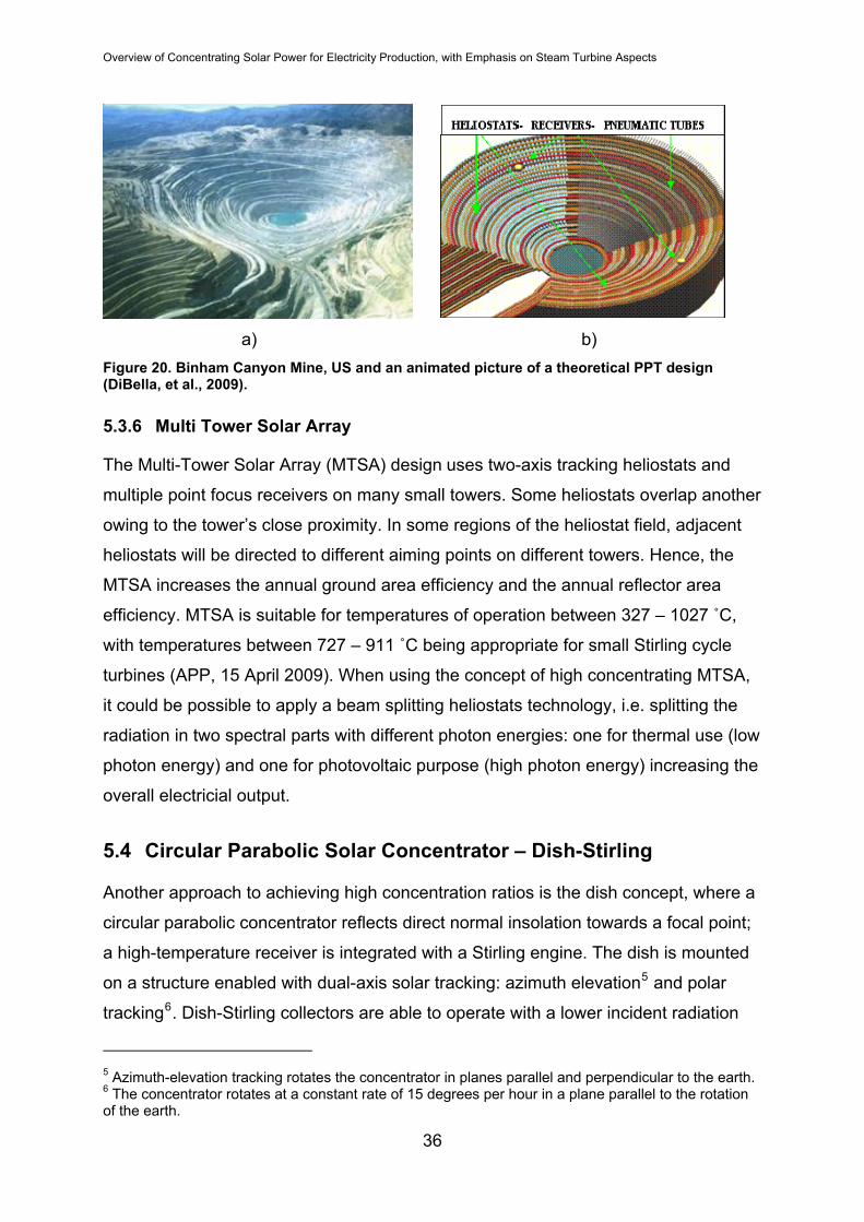
throughout the world exist (see a) b)
Figure 20).
35
Overview of Concentrating Solar Power for Electricity Production, with Emphasis on Steam Turbine Aspects
a) b)
Figure 20. Binham Canyon Mine, US and an animated picture of a theoretical PPT design (DiBella, et al., 2009).
5.3.6 Multi Tower Solar Array
The Multi-Tower Solar Array (MTSA) design uses two-axis tracking heliostats and
multiple point focus receivers on many small towers. Some heliostats overlap another
owing to the tower’s close proximity. In some regions of the heliostat field, adjacent
heliostats will be directed to different aiming points on different towers. Hence, the
MTSA increases the annual ground area efficiency and the annual reflector area
efficiency. MTSA is suitable for temperatures of operation between 327 – 1027 ˚C,
with temperatures between 727 – 911 ˚C being appropriate for small Stirling cycle
turbines (APP, 15 April 2009). When using the concept of high concentrating MTSA,
it could be possible to apply a beam splitting heliostats technology, i.e. splitting the
radiation in two spectral parts with different photon energies: one for thermal use (low
photon energy) and one for photovoltaic purpose (high photon energy) increasing the
overall electricial output.
5.4 Circular Parabolic Solar Concentrator – Dish-Stirling
Another approach to achieving high concentration ratios is the dish concept, where a
circular parabolic concentrator reflects direct normal insolation towards a focal point;
a high-temperature receiver is integrated with a Stirling engine. The dish is mounted
on a structure enabled with dual-axis solar tracking: azimuth elevation5 and polar
tracking6. Dish-Stirling collectors are able to operate with a lower incident radiation
5 Azimuth-elevation tracking rotates the concentrator in planes parallel and perpendicular to the earth. 6 The concentrator rotates at a constant rate of 15 degrees per hour in a plane parallel to the rotation of the earth.
36
Overview of Concentrating Solar Power for Electricity Production, with Emphasis on Steam Turbine Aspects
than other CSP technologies, 800–900 W/m2 (EPRI, 2008). Concentration ratios can
reach high levels >13000 and is claimed to have the highest net efficiency for current
CSP technologies, up to 27% (Fraser, 2008).
The dish-concentrator reflects the solar radiation to the receiver mounted at its focal
point that converts the heat to electricity by a thermal fluid driving a Stirling engine.
The engine’s working fluid should have high heat transfer capabilities at high
velocities and high pressures (Fraser, 2008).
5.4.1 Dish-Stirling System Characteristics, and Comparison to Other Technologies
The Stirling engine converts thermal energy from the absorber to mechanical power
by applying heat externally to a working fluid. The working fluid is contained within
cylinders of the engine component in a closed loop. A regenerator inside the closed
loop improves the efficiency by pre-cooling the working fluid as it moves from the
expansion space to the compression space, and pre-heating the working fluid as it
moves from the compression space into the expansion space. The compression
space is cooled by a secondary loop where a refrigerant circulates through a
common radiator with forced air cooling provided by a fan. Dish-Stirling Engines have
the highest specific work output for any closed regenerative cycle but have a slower
response to an increase or decrease in load. Further details concerning the
mechanics of Stirling engines are beyond the scope of this report.
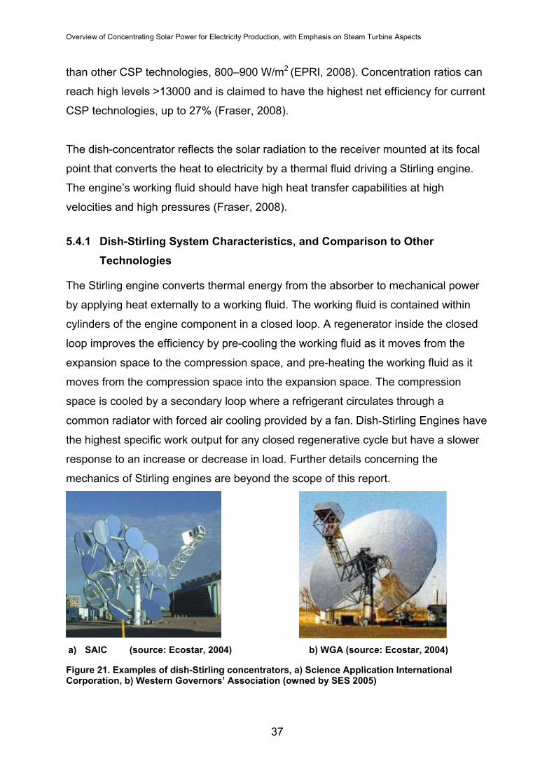
a) SAIC (source: Ecostar, 2004) b) WGA (source: Ecostar, 2004)
Figure 21. Examples of dish-Stirling concentrators, a) Science Application International Corporation, b) Western Governors’ Association (owned by SES 2005)
37

Overview of Concentrating Solar Power for Electricity Production, with Emphasis on Steam Turbine Aspects
ANU Big Dish, 400 m2 (source: Ecostar, 2004)
Figure 22. Australian National University dish-Stirling concentrator.
According to Lovegrove, et al. (2006) the ANU (Figure 26) dish concentrator, with an
area 400m2, is considerably larger than any other solar dishes produced elsewhere
in the world. Even if the overall trend by other developers have been to increase size
over the years, 200m2 is the next biggest to have been built since 1994. The
concentrator is composed of triangular mirror elements attached to the dish-frame,
and delivers a peak concentration ratio of 1500. The receiver is a monotube boiler
housed in a cross section cavity receiver that produces up to 100 g/s of steam that is
superheated to typically 500°C at 4.5 MPa. Dish receivers of this kind could possibly
provide steam at any temperature and pressure that commercially available steam
turbines can work with.
A CSP dish’s optical efficiency is considerably higher than the trough or tower
systems as the mirror continuously is controlled to receive the direct insolation,
whereas the trough and tower suffer from a reduction in projected area due to a
frequent low angle of incidence (cosine losses). Even so the dish systems share an
almost identical range of analogous system components at the same level of
development as tower systems.
5.4.2 Dish Concentrator
The parabolic concentrator must be designed large enough to transmit a significant
fraction of reflected radiation from the concentrator on to the absorber. At the same
time the size of the dish is constrained by structural limitations, including the weight
38

Overview of Concentrating Solar Power for Electricity Production, with Emphasis on Steam Turbine Aspects
of the Stirling engine, receiver, and other components; moreover the dish must be
rotatable. Commercial Stirling dish systems are commonly of the size 10 kWe and 25
kWe with an approximate diameter of the parabolic dish of 7.5 and 11 meters
respectively (Figure 21and Figure 23) (Fraser, 2008). However, at the Australian
National University a 400 m2 dish Stirling solar collector (Figure 22) has been
recomissioned for commercial development and is now a subject for improvement of
its components (Lovergrove K., 2006).
a) SES Suncatcher (Tessera Solar Inc.) b) SBP (Ecostar, 2004)
Figure 23. Examples of dish-Stirling concentrators. a) Stirling Engine System, b) Schlaich Bergermann und Partner
The most durable mirror surfaces of silver/glass have reflectance ranges according to
the presentation of Fraser (2008) between 91-95 %. A polymer reflective film that has
optical properties of 94.5 % mirror reflectivity has been developed and the most
innovative parabolic mirrors use stretched-membranes across a hoop or rim with a
second membrane placed behind the first. A partial vacuum then pulls the first
membrane into a parabolic shape.
The intercept factor of a dish Stirling engine system is the fraction of solar radiation
reflected from the dish that enters the receiver aperture. It is influenced by the size of
the aperture, the collector system, the collector rim angle7 and nonparallel sunlight.
Increasing the intercept factor increase the fraction of the energy entering the
aperture (Fraser, 2008).
7 Angle of the concentrator’s curvature.
39
Overview of Concentrating Solar Power for Electricity Production, with Emphasis on Steam Turbine Aspects
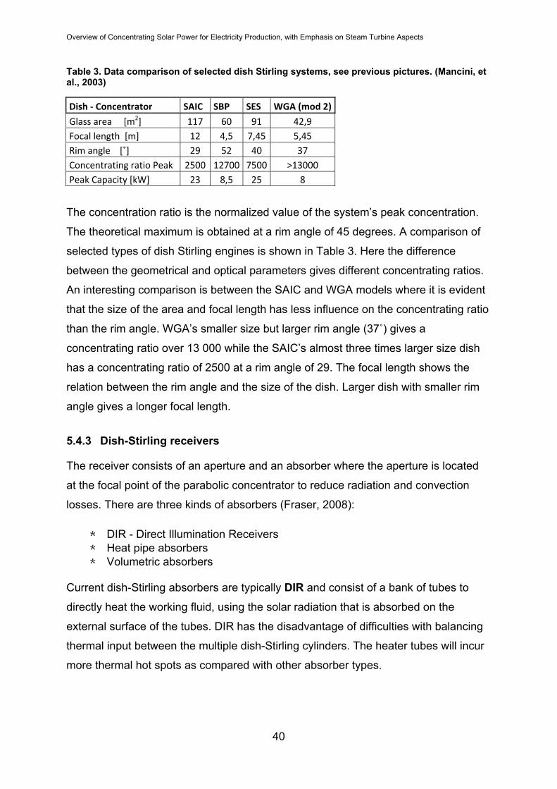
Table 3. Data comparison of selected dish Stirling systems, see previous pictures. (Mancini, et al., 2003)
Dish ‐ Concentrator SAIC SBP SES WGA (mod 2)
Glass area [m2] 117 60 91 42,9 Focal length [m] 12 4,5 7,45 5,45 Rim angle [˚] 29 52 40 37 Concentrating ratio Peak 2500 12700 7500 >13000 Peak Capacity [kW] 23 8,5 25 8
The concentration ratio is the normalized value of the system’s peak concentration.
The theoretical maximum is obtained at a rim angle of 45 degrees. A comparison of
selected types of dish Stirling engines is shown in Table 3. Here the difference
between the geometrical and optical parameters gives different concentrating ratios.
An interesting comparison is between the SAIC and WGA models where it is evident
that the size of the area and focal length has less influence on the concentrating ratio
than the rim angle. WGA’s smaller size but larger rim angle (37˚) gives a
concentrating ratio over 13 000 while the SAIC’s almost three times larger size dish
has a concentrating ratio of 2500 at a rim angle of 29. The focal length shows the
relation between the rim angle and the size of the dish. Larger dish with smaller rim
angle gives a longer focal length.
5.4.3 Dish-Stirling receivers
The receiver consists of an aperture and an absorber where the aperture is located
at the focal point of the parabolic concentrator to reduce radiation and convection
losses. There are three kinds of absorbers (Fraser, 2008):
* DIR - Direct Illumination Receivers * Heat pipe absorbers * Volumetric absorbers
Current dish-Stirling absorbers are typically DIR and consist of a bank of tubes to
directly heat the working fluid, using the solar radiation that is absorbed on the
external surface of the tubes. DIR has the disadvantage of difficulties with balancing
thermal input between the multiple dish-Stirling cylinders. The heater tubes will incur
more thermal hot spots as compared with other absorber types.
40
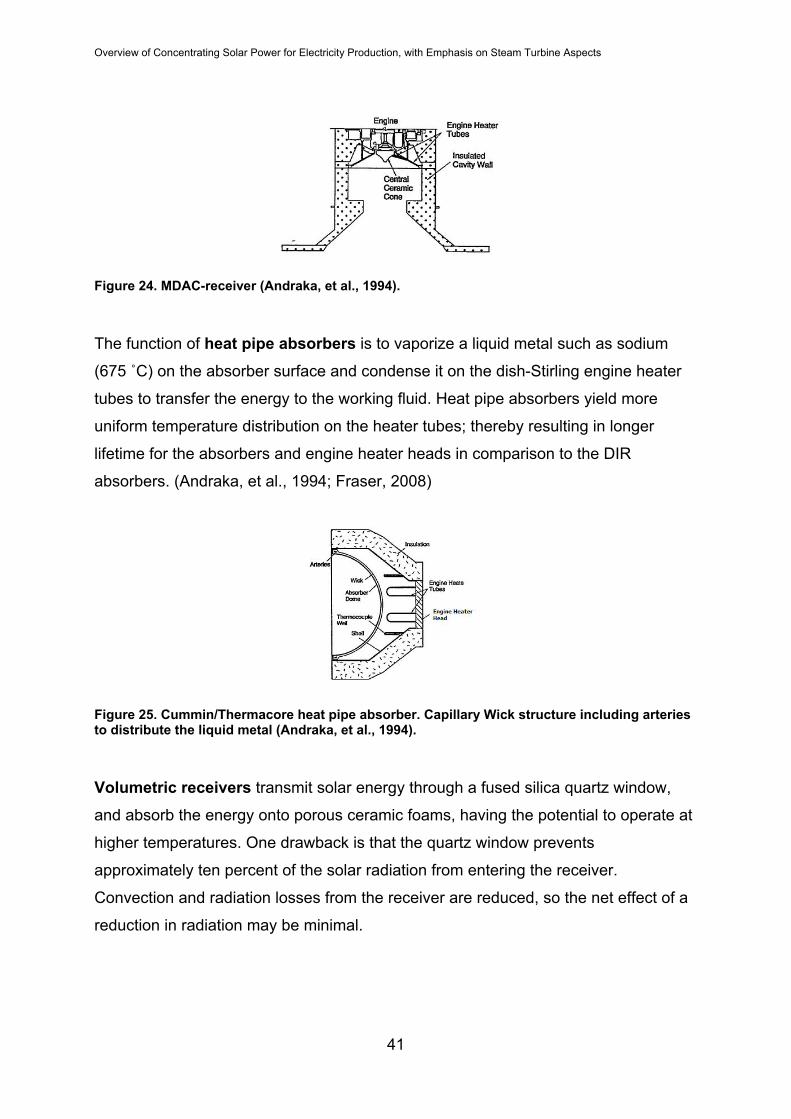
Overview of Concentrating Solar Power for Electricity Production, with Emphasis on Steam Turbine Aspects
Figure 24. MDAC-receiver (Andraka, et al., 1994).
The function of heat pipe absorbers is to vaporize a liquid metal such as sodium
(675 ˚C) on the absorber surface and condense it on the dish-Stirling engine heater
tubes to transfer the energy to the working fluid. Heat pipe absorbers yield more
uniform temperature distribution on the heater tubes; thereby resulting in longer
lifetime for the absorbers and engine heater heads in comparison to the DIR
absorbers. (Andraka, et al., 1994; Fraser, 2008)
Figure 25. Cummin/Thermacore heat pipe absorber. Capillary Wick structure including arteries to distribute the liquid metal (Andraka, et al., 1994).
Volumetric receivers transmit solar energy through a fused silica quartz window,
and absorb the energy onto porous ceramic foams, having the potential to operate at
higher temperatures. One drawback is that the quartz window prevents
approximately ten percent of the solar radiation from entering the receiver.
Convection and radiation losses from the receiver are reduced, so the net effect of a
reduction in radiation may be minimal.
41

Overview of Concentrating Solar Power for Electricity Production, with Emphasis on Steam Turbine Aspects
Figure 26. Example of a volumetric receiver. (Diver, Richard B., et al.)
5.4.4 Receiver Losses
The majority of the overall thermal losses of a concentrator dish-system is generated
from the receiver, responsible for up to 56-74%8, while the reflector losses due to the
mirror reflectivity comprise between 24-37 % of the total losses. The conduction
losses are minimal in the dish- Stirling receiver since they can be easily controlled by
adding insulation without large losses in other components. The convective losses
may represent up to 25 % of receiver losses during noon, and up to 40 % during the
morning and evening. Convective losses are a function of cavity temperature and
geometry, aperture orientation and diameter and wind velocity (forced convection).
These losses are also dependent on the time of year and location since the angle
between the sun and a horizontal surface changes with the season. The Radiation
losses in the receiver may represent up to 60 % of receiver losses during the
morning and evening, and about up to 75 % at noon (Fraser, 2008).
A 25kW dish-stirling collector needs only a landarea of about 510 m2, able to produce
55 - 60 MWeh/year. In both US and Spain plans for 25 kW dish-Stirling Engine
clusters for grid deployment are under way. (Stirling Energy, 2008)
A comparison presented by Lovegrove (2006) between CSP technologies: parabolic
trough, power tower and dish-Stirling, showed the annual overall insolation to electric
efficiency, ɳte , to be highest for the dish-Stirling (14 %) and lowest for the parabolic
trough system (11%), with the power tower concept close to the dish-Stirling’s
efficiency. To be noted is the peak capacity for the dish-Stirling (1 MWe) system that
8 SES and WGA dish-Stirling systems. (Fraser, 2008)
42

Overview of Concentrating Solar Power for Electricity Production, with Emphasis on Steam Turbine Aspects
is 30 times less than for the parabolic trough (30 MWe) and 14 times less for the
power tower (14 MWe) for the stated efficiencies. The most significant differences
between the technologies lay in the solar field optical efficiencies and receiver
thermal efficiencies between the parabolic trough/power tower- and the dish-Stirling
system, that are 30 % and 10 % higher respectively. More, the power cycle efficiency
is highest for the power tower system (40%) and lowest for the dish-Stirling (27%)
with the parabolic trough system efficiency of 35 %.
6 THERMAL STORAGE FOR CSP
Operational flexibility and economic feasibility of CSP plants depend a great deal
upon thermal energy storage (TES) approaches. The TES storage media has to
meet a number of essential constraints: high energy density; high thermal stability
(exceeding 425 C); low or non-toxicity; non-flammability; compatibility with other
materials (non-corrosiveness); and low cost. Mechanical and chemical stability of the
container are equally important as compatibility between the heat transfer fluid, heat
exchanger and storage media. The TES-system has to be able to operate within the
solar fluctuation behavior and be well integrated into the power plant, having optimal
operation parameters and strategy with minimum heat losses to the surroundings
during multiple charging/discharging cycles. Research is continuously done to
develop different storage systems as well as the heat transfer fluid that can be used
in both the solar field and the storage system. The thermal conductivity of the media
gives information about the media influence on the heat transfer design and the heat
transfer surface requirements on the storage system. Designing the thermal plant
aims for high volumetric heat capacity improving the TES by reducing the size,
external piping and structural costs. The most common thermal storages in CSP
commercial use are of pressurized steel drums for steam or water and molten salt
storages.
43

Overview of Concentrating Solar Power for Electricity Production, with Emphasis on Steam Turbine Aspects
TES systems can be classified according to the storage media system or the storage
concept as seen in Figure 27 and Figure 30.
- Sensible Heat Compressed Air
- Latent Heat Mechanical Energy
Thermal Energy
CSP TES MEDIA SYSTEMS
Figure 27. Thermal Energy Storage based on storage media.
6.1 Sensible heat and latent heat TES
Sensible heat means changing the internal energy of a media without changing its
phase. The material temperature increases and thermal energy is stored until
discharging by decreasing the temperature. The important properties of a sensible
heat storage material are the ability to conserve heat per unit mass9, and the material
average density as well as operational temperature, vapor pressure, compatibility
among materials, stability and surface area/volume ratio and heat loss coefficient.
Thermal energy can be stored by latent heat of phase change in some media. The
latent heat energy absorption is a reversible isothermal process between two phases.
When a phase change from solid to liquid state occurs, the material absorbs energy
in the melting process at an almost constant temperature and releases energy in the
reversible transition back to solid phase. The melting process is limited by thermal
conductivity and natural convection, and the solidification process is mainly limited by
thermal conductivity. Other phase change states are solid to solid crystalline phase
transformation and liquid to vapor. Due to the isothermal process the latent heat
storage has the advantage over sensible heat storage systems, where the
temperature drops as the storage is discharged. (Hoshi. et al., 2004). Also beneficial
9 Specific heat capacity.
44

Overview of Concentrating Solar Power for Electricity Production, with Emphasis on Steam Turbine Aspects
is that the vessel containing the latent energy media is not exposed to significant
thermal stresses and can be reduced in size compared to the single-phase sensible
heating systems. A solid-solid phase change, that some salts exhibit a major stress
effect on the storage container at multiple cycling (Hoshi. et al., 2004). Sodium
chloride as a solid media has a heat capacity per unit mass comparable to concrete
(kW/kg) but 50% less heat capacity per unit volume (see Appendix 3, table 17).
6.1.1 Sensible Heat TES - Media
Gas media must be stored under pressure to maintain sufficient amount of heat at a
certain volume and requires large storage volume. Multiple steel drums are used at
CSP-plants where this concept is chosen mainly where DSG in the solar field can
drive a steam turbine directly. Liquid media for sensible heat storages are thermal
oils and various salt mixtures. Thermal oils are liquids at room temperature and thus
a more convenient to handle, but some are environmentally questionable due to their
toxic nature. Salt mixtures are solid, having a higher freezing point up to 200 ˚C
(Knutsson A, 2008). A higher freezing point gives higher technical and economical
limitations when it comes to auxiliary heating during off-operating hours.
Thermal oils are essentially petroleum based mineral oils for TES-systems up to
350ºC (See Appendix 2, table 15). Thermal oils becomes unstable above 300 – 350
ºC (Knutsson, 2008), where they change properties, so they are inappropriate for
high temperature storage, i.e. Power Tower. Synthetic mineral oils with improved
properties and higher temperature range are now commonly used in the CSP system
today, for example parabolic trough systems (see Table 2).
Salt mixtures cover the temperature range from 120-1400 ºC; the thermal
characteristics increasing with increasing temperature (see Appendix 3, table 16).
Today the nitrates (-NO3), nitrites (-NO2) and carbonate (–CO3) salts are under
consideration for TES use (Knutsson, 2008). Mixtures of eutectic inorganic salts with
wide temperature range like 60 % potassium nitrate and 40 % sodium nitrate have
proven to be satisfactory as TES media with a freezing point of 221ºC.10 An eutectic
mixture called HITEC made up of nitrate salts (NaNO3, 7% / KNO3, 53%) and
10 Also called ”Solar salt”. (Knutsson A, 2008)
45

Overview of Concentrating Solar Power for Electricity Production, with Emphasis on Steam Turbine Aspects
potassium nitrite salt (NaNO2, 40%) have proven a lower freezing point of 142 ºC,
due to the nitrite salt lowering the freezing point (Pilkington Solar Int., 2000). A third
salt called HITEC XL combined of 48 % Ca(NO3)2, 7 % NaNO3 and 45 % KNO3 has
shown a freezing point interval between 87 – 130 ºC (Kearney, et al., 2001). Thus the
storage material is more resistant to unwanted freezing in the case of power plant
shutdown or long time of no insolation. In general fused salts are highly corrosive and
inhibitors are required to prevent corrosion. Other examples of salts useful as thermal
storage media are: phosphates (-PO4), oxides (-O), sodium chloride, magnesium
chloride and aluminum chloride. See Appendix 3, table 18 for more information
The carbonates have the best heat values of all salt types (see Figure 28; Appendix
3, table 15). Having the best volume specific heat capacity, the carbonates are able
to store energy at one third the space nitrites would need for storage of the same
energy amount, and about at half the space of nitrates. More, nitrate salt has higher
specific heat capacity per unit volume than the nitrite salt and is able to store 50 %
more thermal energy (Knutsson, 2008). Nitrates are highly corrosive at high
temperatures. To reduce the corrosive effect, nitrite can be added (Knutsson, 2008).
Liquid metals like sodium and sodium-potassium have properties similar to water,
good heat transfer characteristics and have high temperature ranges while
maintaining the thermal storage capacity and stability. A liquid sodium metal storage
tank would need less volume than for the thermal oil to store the same amount of
thermal energy (see Appendix 3, table 15). This is due to the floating sodium which
compared to synthetic mineral oil has adequately higher volume specific heat
capacity. Liquid metals could be considered for high temperature TES applications,
particularly where high heat transfer rates are needed. They have however high
reactivity with container material, water and air as well as low specific heat
properties11 (see Appendix 3, table 15). When properly contained and maintained the
liquid metals can minimize the corrosive impact.
11 For high temperature sensible TES-systems, liquid metals has an average heat capacity. (Knutsson A., 2008)
46

Overview of Concentrating Solar Power for Electricity Production, with Emphasis on Steam Turbine Aspects
Examples of solid media usable for thermal storage is castable ceramic, concrete,
sodium chloride, cast iron, cast steel, silica- and magnesia fire bricks (see Appendix
3, table 17). A castable ceramic has lower material strength compared to concrete
but has better durability and resistance to cracks. 12 There is also a thermal
expansion to regard when calculating the storage container. By comparison
magnesia brick has the highest heat capacity yet low heat conductivity. Cast steel
and cast iron has up to 40 times higher thermal conductivity than other tabulated
solid materials except for solid sodium chloride and magnesia bricks (see Appendix
3, table 17). Most solid metals are not relevant for TES applications, consider low
heat of fusion per unit weight or volume, unfavourable chemical properties and in
some cases toxicity (Knutsson, 2008). Solid media heat storage could be an
attractive option for parabolic trough power plants that uses synthetic oil as the heat
transfer medium. Two storage systems of castable ceramic and high-temperature
concrete have been tested at PSA in Spain (EPRI, 2006). The two concepts proved
suitable, had integrated tubular heat exchanger between the thermal oil and the
storage media. The high-temperature concrete would be the superior thermal storage
cause of its lower cost, higher material strength, and easier handling.
6.1.2 Latent heat TES – PCM’s
Utilizing the latent heat involved in a phase change of a media is the definition of the
phase change materials (PCM) technology. During liquid to gas transition, the latent
heat media in gas phase has high energy per unit mass of the storage medium, thus
less mass of storage material is necessary. The disadvantage with liquid to gas
phase change media is the average heat capacity per volume is small and requires
large volume of the storage container due to the gas-phase. In CSP plants where the
heat transfer fluid in the solar field contains a two-phase media water/steam, multiple
steel drums are used as thermal storage.
The most interesting PCM option for intermediate and high temperature storage is
the melting-freezing phase change of salt compositions such as nitrates,
hydroxides, salt ceramics, and chlorides. For a PCM to be a relevant choice for
parabolic trough solar power plant storage, the phase change temperature of the
12 Thermal expansion Coefficient 11.8, [10-6/K], Castable Ceramics, DLR
47

Overview of Concentrating Solar Power for Electricity Production, with Emphasis on Steam Turbine Aspects
material should be in the interval suitable the storage to provide the Rankine cycle
with thermal energy.
Studies of PCMs as storage element in a parabolic trough system13 shows that some
salt mixtures like NaOH/Na2CO3 have a superior heat capacity to single salts of
similar melting point such as NaNO2 (see Appendix 3, table 18). Above this
temperature and up to 427 ˚C, metals such as Sn and Zn can be used as PCM’s
(Hoshi, et al., 2004).
For Fresnel systems according to Hoshi, et al. (2004) and Tamme, et al., (2003)
using low pressure turbines at or below 327˚C and 25 bar, the salts NaNO2, NaNO3
and KNO3 are interesting PCM’s with saturated steam as heat transfer fluid. Figure
28 and table 18, Appendix 3, show PCM’s with phase change temperatures reaching
900 ºC. Mixtures of these salts as main ingredient give different suitable phase
change temperatures for TES systems.
Figure 28. Various PCM material/molten salts, thermal conductivity – Melting point relation. (Hoshi, et al., 2004)
13 Thermal oil as heat transfer fluid.
48

Overview of Concentrating Solar Power for Electricity Production, with Emphasis on Steam Turbine Aspects
Viewing Figure 28, for MTSA-technology (see section 5.3.6), high melting point
media with high thermal conductivity such as Na2CO3 should be of interest in the
latent heat TES-systems. It should be noted that in general the melting point and the
heat capacity tend to increase in the order of nitrates, chlorides, carbonates and
fluorides.
Three generic configurations for PCM thermal storage systems have been identified
in the report by Luz Int., et al., (1988):
- Shell-and-tube heat exchangers. PCM contained in the tubes while the heat
transfer fluid circulates on the shell side or vice versa
- Packed bed configuration with encapsulated PCM spheres contained in a pressure
vessel.
- Direct contact configuration between the PCM and the heat transfer fluid
The storage systems utilizing latent heat PCM’s can be reduced in size compared to
single phase sensible heating systems. This is due to the relative high latent heat of
fusion between the liquid and the solid state. There could however be a limit to the
number of freezing and melting cycles where degradation of the PCM material
reduces the performance of the TES storage (Zalba et al., 2002). In the intermediate
and high temperature ranges, there is also a risk of corrosive effect of the phase
change material on the container. More, the low heat conductivity prevents the full
use of PCM storage technology, but the heat transfer in the storage tanks can be
improved choosing the PCM in such a way that its phase change temperature
optimizes the thermal gradient with respect to the opposing heat transfer media.
The maintenance of the storages has an elevated risk of high parasitic loads due to
daily processes of filling and emptying the receiver and ducts (Solúcuar Solar S.A,
2006).
There are efforts to develop the sensible and latent TES medias to achieve a high
temperature, low vapor pressure, low melting point heat transfer fluids that would
eliminate the weaknesses of both the synthetic oils and molten salts, while
simultaneously providing both short- and long-term thermal energy storage.
Examples of other possible heat transfer fluids are: molecular alloys phase change
49

Overview of Concentrating Solar Power for Electricity Production, with Emphasis on Steam Turbine Aspects
material (MCPAM) (Zalba, et al., 2002) that are thermo-adjustable14; presented by
Moens (2004) are plasticizers, modified high temperature lubricants such as esters
and modification of commercial fluid such as Therminol VP-1TM ; nanoPCMs15
(Glatzmaier, et al., 2008) and microencapsulated phase change material (MCPCM)
(Yamagashi, et al., 1998). Introducing the MCPCM particles in the collector loop, the
heat transfer fluid could serve for a short-term buffer storage as the effective specific
heat of the heat transfer fluid increases. The particles might also be separated from
the heat transfer fluid and stored in a vessel as a long term storage, until needed for
discharging at which point they would be reintroduced into the heat transfer fluid
stream. The potential risks are erosion of pumps, valves and other collector loop
components, as well as difficulties of encapsulation and the complexities of the
separation and storage phases. Research on ‘room temperature ionic liquids’ such
as imidazolium salts has shown very high thermal stability (over 400˚C), almost no
vapour pressure, low melting point and are non flammable although these salts are
thermally unstable for typical CSP-technology temperatures (Moens, 2004). In
Appendix 3 tables 15 through18 of the discussed TES media can be viewed.
6.2 Chemical Energy Storage (CES)
Chemical storage is storing thermal energy by utilization of the energy in reversible
endothermic/exothermic chemical reactions. The solar thermal energy excites an
endothermic chemical reaction that should ideally be completely reversible
(Pilkington Solar Inc., 2000). Since it is important to control the thermal energy
exchange, catalyst induced exothermic chemical reactions are favorable. This
process is called reversible thermo-chemical reaction (RTR). The advantages are
high storage energy density, long storage duration at near ambient temperature and
heat pump capability. Unfortunately CES media show uncertainties in the
thermodynamic properties and the reaction kinetics as well as being toxic and
flammable. CES media such as electrochemical flow batteries capable of storage
times for several minutes or hours have been demonstrated at utility scale but not yet
in conjunction with solar energy systems (EPRI, 2006).
14 The material’s composition allow temperature phase change altern tion. a15 Nanoscale “encapsulated” structures (50 – 500 atoms) capable of phase transitions.
50
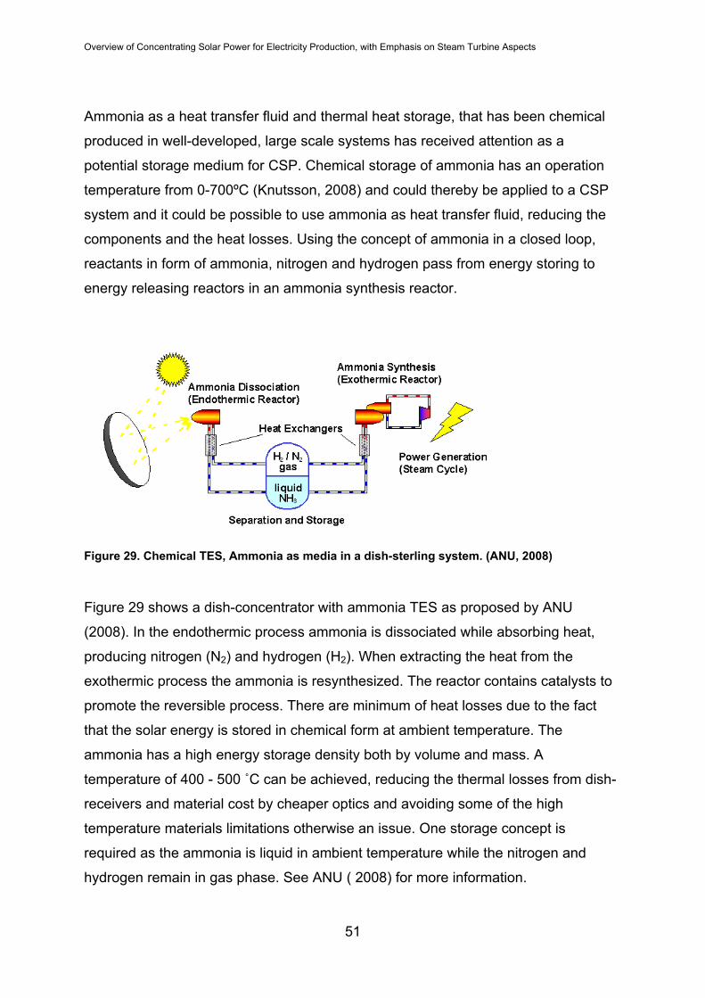
Overview of Concentrating Solar Power for Electricity Production, with Emphasis on Steam Turbine Aspects
Ammonia as a heat transfer fluid and thermal heat storage, that has been chemical
produced in well-developed, large scale systems has received attention as a
potential storage medium for CSP. Chemical storage of ammonia has an operation
temperature from 0-700ºC (Knutsson, 2008) and could thereby be applied to a CSP
system and it could be possible to use ammonia as heat transfer fluid, reducing the
components and the heat losses. Using the concept of ammonia in a closed loop,
reactants in form of ammonia, nitrogen and hydrogen pass from energy storing to
energy releasing reactors in an ammonia synthesis reactor.
Figure 29. Chemical TES, Ammonia as media in a dish-sterling system. (ANU, 2008)
Figure 29 shows a dish-concentrator with ammonia TES as proposed by ANU
(2008). In the endothermic process ammonia is dissociated while absorbing heat,
producing nitrogen (N2) and hydrogen (H2). When extracting the heat from the
exothermic process the ammonia is resynthesized. The reactor contains catalysts to
promote the reversible process. There are minimum of heat losses due to the fact
that the solar energy is stored in chemical form at ambient temperature. The
ammonia has a high energy storage density both by volume and mass. A
temperature of 400 - 500 ˚C can be achieved, reducing the thermal losses from dish-
receivers and material cost by cheaper optics and avoiding some of the high
temperature materials limitations otherwise an issue. One storage concept is
required as the ammonia is liquid in ambient temperature while the nitrogen and
hydrogen remain in gas phase. See ANU ( 2008) for more information.
51

Overview of Concentrating Solar Power for Electricity Production, with Emphasis on Steam Turbine Aspects
6.3 Mechanical Energy Storage (MES)
Compressed air energy storage (CAES) is a relatively mature large-scale energy
storage technique. CAES uses electrically driven compressors to charge an
underground reservoir during off-peak hours. When needed, air is discharged from
the reservoir into an expansion turbine connected to a generator. Alabama electric
cooperative built a 110-MW CAES facility in 1991 with EPRI participation and more
recent projects have proposed taking advantage of salt caverns in Texas and
limestone mines in Ohio. (EPRI, 2006)
6.4 Thermal Energy Storage concepts (TES)
Thermal energy storage concepts can be divided into active and passive storages
(Gil, et al., 2008) (see Figure 30). Both active and passive storages can be
subdivided in direct and indirect storages. Direct indicates the solar field heat transfer
fluid is also used as the storage medium. In an indirect storage system the solar field
heat transfer fluid is separated from the storage medium via a heat exchanger. Direct
storage systems eliminate losses associated with the heat exchanger used in indirect
systems. However, some solar field heat transfer fluids have pressurization
requirements that would make direct storage systems too expensive, where indirect
system design shows the flexibility by using different fluids in the solar field and
storage system. Thermal energy storage approaches include the single tank
thermocline (in which hot and cold heat transfer fluids are stored in the same
stratified tank), the single tank trickle-charge thermocline (in which the tank contains
a large volume fraction of low-cost sensible heat storage media and the heat transfer
fluid is trickled over the media), the two-tank molten salt systems and the dual media
systems (in which the heat transfer fluid is pumped through pipes imbedded in the
storage media.
52

Overview of Concentrating Solar Power for Electricity Production, with Emphasis on Steam Turbine Aspects
CSP TES CONCEPT
Active System Passive System
Figure 30. Thermal energy storage based on passive and active systems.
Two-tank thermal energy storage systems use two reservoirs, a hot tank and cold
tank, to store thermal energy. To charge the direct system, high temperature fluid
exiting the solar field is accumulated in the hot tank while low temperature fluid is
pumped from the cold tank to the solar field. When discharging, the fluid in the hot
tank is pumped to provide thermal energy to the power cycle and before returning to
the cold tank.
Molten salt storage is a proven technology that has been used in the process
industry. Andasol-1 molten salt 2-tank is a liquid TES (see Figure 1), classified as a
passive indirect storage concept. The storage capacity is totally 1010 MWh thermal
energy (Nava, et al., 2006), constructed for 7,5 hrs dispatchability. Two separate
tanks are connected to the CSP system through a heat exchanger. The hot tank
operates at a temperature of 385ºC and the cold tank at a temperature of 292ºC.
During the day the molten salt is pumped from the cold tank to the hot tank at a flow
rate of 948 kg/s. The molten salt passes the oil-to-salt-heat exchanger, is heated up
and continues as hot molten salt to the hot storage tank where the solar thermal
energy is stored. At the same time the thermal oil is cooled down, before it returns to
the solar field for reheating. Whenever heat is needed, the hot molten salt is pumped
back to the cold tank, transferring thermal energy to the Rankine cycle, and cooling
down the storage material while this is returning till the cold tank (Knutsson, 2008).
Direct Indirect
-Direct Steam
Indirect Direct
- Two tanks - Single tank Thermocline Dual media - Cascade - Single tank Trickle - Concrete
- Ceramics Charge Thermocline
53

Overview of Concentrating Solar Power for Electricity Production, with Emphasis on Steam Turbine Aspects
The molten salt media used in the Andasol 1 storage concept is HITEC, see section
6.1.1. The mixture provides better overall thermal characteristics than the salts
individually, though closer to the nitrate single salt values. The downside of molten
salt in CSP system is that of preventing the molten salt to freeze and solidify. There
are ways to avoid solidification by heating through electric, internal resistance or
impedance heating. Internal resistance heating is possible but cumbersome.
Impedance heating gives a uniform heating but is as for electricity heating, electricity
demanding. Care has to be taken of the choice of joints, seals and packings for
molten salt components – graphite seals are incompatible with molten salt. Boron
nitride is chemically suitable and could be an alternative (Moreno, 2003). Using
Therminol™VP-1 or a similar synthetic heat transfer oil in the solar parabolic trough
absorbers generally require an indirect system for tank storage concepts. High-
temperature heat transfer fluids such as the thermal oils have relatively high vapor
pressures at required operating temperatures. As a result storage tanks require
pressurization which dramatically increases storage tank complexity and cost. Molten
salts are commonly considered as the indirect storage medium. They offer the
advantage of having a much lower vapor pressure but they have the disadvantage of
high freezing temperatures (100ºC-220ºC), currently available used both as a storage
medium and as a solar field fluid (McMahan, 2006).
A thermocline storage tank refers to the stratification that occurs in a tank with a
large volume. A sharp fluid temperature gradient (stratification) develops between
high and low temperature fluid caused by fluid buoyancy resulting from the variation
in fluid density with temperature. The stratified thermal energy storage concept can
be improved by adding a solid storage medium to the storage tank (McMahan, 2006).
The purpose of the solid medium is to maintain thermal mass while reducing the
required fluid volume for a given storage capacity. A temperature gradient forms in
the solid as well as the liquid. The advantage is the use of inexpensive solid media
(rock, sand, concrete) together with more expensive heat transfer fluids. Parasitic
energy consumption and pressure drop could however be high is such system
(Pilkington Solar Inc., 2000).
54

Overview of Concentrating Solar Power for Electricity Production, with Emphasis on Steam Turbine Aspects
Packed bed such as concrete storage is essentially the same as the stratified
storage tank with added filler material. A solid concrete storage can also be termed
high temperature sensible heat storage. The heat transfer fluid flow from the solar
collector field is divided into smaller identical tubes, located in a square formation
embedded in the solid block storage unit. The numerous tubes improve heat
exchange between the heat transfer fluid and the storage as the area of heat transfer
is larger. This alternative eliminates the heat exchanger otherwise necessary for an
indirect molten salt rock bed storage system and leads to improved storage system
performance and reduces cost (McMahan, 2006). However, it demands a structured
rather than randomly packed bed, and the long-term structural stability of the cast
concrete structures following multiple thermal cycles has to be evaluated. A thermocline solid storage tank of quarzite rock and silica sand offer an inexpensive
filler material where quartzite has a higher thermal conductivity than most other rocks
and does not deteriorate from prolonged exposure to the molten salt environment ,
making it attractive for solid TES (Brosseau, et al., 2005).
Figure 31. PCM-cascade TES concept for parabolic trough CSP (reproduced from Knutsson, 2008).
A phase change cascade storage tank is an example of storing latent heat, using
several different salts with thermal properties and phase change temperatures in the
range of 306-380 ºC. PCM cascade storage concept is shown in Figure 31, where
55

Overview of Concentrating Solar Power for Electricity Production, with Emphasis on Steam Turbine Aspects
five tubular heat exchanger stages holding five salts made up of either single salts or
eutectic mixture of several salts (see Table 4) covering the range of 306-380˚C.
Table 4. PCM cascade salts used in TES for parabolic trough CSP. (Knutsson, 2008))
Tubular heat
exchanger PCM Average melting Average Enthalpy change
Temperature density during melting # [ºC] [Kg/m3] [Kj/kg]
1 MgCl2/KCl/NaCl 380 1800 400
2 KOH 360 2040 134
3 KNO3 335 2109 95
4 KNO3/KCL 320 2100 74
5 NaNO3 306 2261 172
The cascade configuration salts absorb most of the heat as they melt at practically
constant temperature, starting at 380ºC (1st salt), while the heat transfer oil
temperature drops from 390 ºC at storage inlet to 300 ºC at outlet of the storage,
where the last salt has the melting temperature of 306 ºC. The PCM cascade has
storage density higher than sensible storage of equivalent capacity (McMahan,
2006).
Applications with packed beds or shell-and-tube vessels should consider the heat
transfer limitation due to the pinch-point, the relatively small temperature differences
between the PCM and the charging or discharging. At these points, a large heat
transfer surface area is needed as the relatively small temperature differences drive
the heat transfer.
The pinch-point characteristic is not an issue using direct steam generation but with
cascade arrangement the pinch-point problem would be minimized by replacing it
with a hypereutectic multi component salt for which the liquids have the same
temperature as the maximum heat transfer fluid temperature, and the eutectic
temperature is the same as the turbine inlet temperature. However such operation
would require concurrent flow of the heat transfer fluid during the storage and
utilization cycles (Luz Int., et al., 1988).
56

Overview of Concentrating Solar Power for Electricity Production, with Emphasis on Steam Turbine Aspects
For the packed bed arrangement of PCM's, encapsulation and pressurized designs
are the critical issues. Encapsulation refers to a protective outer layer which isolates
the PCM from the heat transfer fluid and reduces their relative incompatibilities.
Encapsulation for the packed bed arrangement should provide a high surface area
for heat transfer and low resistance for heat conduction within the encapsulated
sphere. A separate pressure vessel is however most likely necessary for collection of
the heat transfer fluid off-gassing. One advantage of the shell-and-tube configuration
over the packed bed configuration is that if the heat transfer fluid is contained in the
tubes, the containment of the off-gases will be simpler and less expensive.
7 POWER BLOCK FEATURES OF CSP PLANTS
Figure 32. Example of a Solar thermal steam power plant for electricity production with no TES and fuel back-up.
Figure 32 shows an example of a concentrating solar steam power plant where the
solar thermal energy is delivered to the Rankine cycle to preheat and evaporate
feedwater and to superheat steam. Superheating the steam will lead to an expansion
mainly in the superheated region of the Mollier chart achieving a higher enthalpy drop
during the expansion, leading to a higher power output. Only the last LP stages will
experience expansion in the two phase region lowering the moisture losses in the
turbine. Moisture contains water droplets that have an impact on the rotor, lowering
the efficiency as well as causing erosion of the blades. Power production by
57

Overview of Concentrating Solar Power for Electricity Production, with Emphasis on Steam Turbine Aspects
expansion of steam drives the turbine rotor i.e. turning the turbine shaft connected to
an electrical generator. The turbine exhaust steam is condensed and returned to the
Rankine cycle as feedwater. A deaerator both removes incondensable gases from
the water/steam cycle and work as a water and heat storage, preventing system
fluctuations. The high content of non condensable gases, especially oxygen could
cause corrosion in the tube bank. The condensate is sometimes sprayed into the
deaerator or it is arranged to pour down from a number of trays to reduce the ratio of
non condensable gases in the feedwater. When heated steam is fed into the
deaerator, the water droplets are heated to the saturation temperature, the
incondensable gases is released and evacuated at the top of the deaerator.
7.1 Steam turbine
The steam turbine operates with a rotational shaft speed range between 1500-6000
rpm. For machines in electrical production the connection towards the electric
generator have to be synchronized with the grid. For a 50 Hz grid the synchronous
rotational speed is 1500 rpm. Both high pressure (HP) and low pressure (LP)
turbines can have higher rotational speed than 1500, but have to be geared down
before connecting to the electric generator. Also the HP turbine and the LP turbine
can be connected to the same electric generator but with different synchronous
rotational speed. For example an HP turbine rotating at 12000 rpm and a LP turbine
rotating at 5000 rpm can both be connected to a four pole generator at 1500 rpm
through gears.
For steam turbines in CSP-plant some characteristics are interesting to distinguish:
saturated vs. superheated steam; reheat and regenerative cycles; and condensing,
backpressure and extraction turbines.
The live steam to the steam turbine is preferably superheated by a steam heating
tube bank in the heat exchanger unit. In some cases the live steam is taken directly
from the evaporator stage leading saturated steam to the turbine.
The difference between superheated and saturated steam is in superheated steam
conditions the saturated steam is heated at the same pressure up to a higher
temperature which gives an increased enthalpy drop at expansion and a higher
58

Overview of Concentrating Solar Power for Electricity Production, with Emphasis on Steam Turbine Aspects
Rankine cycle efficiency. For the saturated steam case, the moisture content is
reduced before the steam is let into the turbine. In more expensive turbine plants the
HP and the LP blading is separated into two or more separate casings. The exhaust
steam from the HP is reheated before entering the LP turbine to conserve the steam
quality. For reheat turbines it is common with three separate casings dividing the
turbine into; high-, intermediate (IP) and low pressure turbines. The IP expands the
steam from the hot reheat HP outlet steam to the inlet LP element. A regenerative cycle uses extracted steam from intermediate pressure outlets to preheat the
feedwater to the steam generator. When the steam plant producing electricity and no
process heat, the best efficiency is reached when the steam turbine operates with
low back-pressure at the outlet before the exhaust steam condenses. When using
the steam for process heat, for example district heating, drying, boiler etc., the back-
pressure has to be higher which allow higher outlet steam temperature to be used for
process heating. In the electricity production condensing turbines are used where
the back-pressure is low, 0.03 - 0,06 bar (Widell, 1965; Ecostar, 2005) and the
enthalpy fall in the turbine is transferred to maximum mechanical power. In Rankine
cycles with a deficit of low temperature heat, steam is extracted from different points
in the turbine to heat feed water in pre-heaters to raise the temperature before the
feed-water is evaporated by the high temperature source. This is to reduce exergy
losses in the cycle and thereby increase the cycle efficiency (low pressure preheater
in Figure 32).
There are significant differences when using the steam turbine in a CSP plant as
compared to other applications. Fluctuation of temperatures and loads are larger and
therefore should such steam turbines for example be flexible and not too sensitive to
thermal stresses. The operation modes for CSP plants differ from a regular steam
plant that operates around the clock all year, only stopping the turbine for service,
inspection and maintenance and the start and stop events are more frequent for
CSP plants than for traditional applications. Low-load operation like gland sealing
and rotor balancing, along with consequences due to heat losses take on much more
importance when steam turbines are stopped and restarted daily.
59

Overview of Concentrating Solar Power for Electricity Production, with Emphasis on Steam Turbine Aspects
Gland Sealing
Steam gland sealing can be used for three reasons: to maintain a vacuum in the
turbine; to prevent oxidation of the turbine via air entrainment and to minimizing heat
losses during stand still (if it is economical beneficial to produce auxiliary steam).
Most steam turbines exhaust into a vacuum where a multiple number of seals
dissipate the turbine pressure and the velocity to the ambient surroundings. Gland
sealing is used where the turbine shaft passes through the casing and shaft walls.
Gland steam 1.1 – 1.3 bar
Figure 33. Example of Gland Sealing steam system.
Viewing Figure 33, the gland steam supply operates with a pressure of 0,1 – 0,3 bar.
Gland steam above atmospheric pressure is introduced and flows inward to be
condensed in the turbine and outward as a slight positive flow to prevent atmospheric
air from entering, exiting into the leakage system at pressure under atmospheric. The
gland steam flows inwards to the turbine when auxiliary heat is needed at stand still
and at start-up. Any air leaking in is forced into the leakage system by its lower
pressure. The air/steam that flows into the leakage system is condensed and reused
in the steam cycle. The amount of gland steam needed depends on several input
parameters, where pressure drop in the system is the most important parameter.
When the turbine is shut down the pressure decreases in the system and the turbine
starts to cool down. The small pressure difference between the ambient air and the
leakage system could lead to air/steam leakage into the turbine, if the turbine is
cooled down to a level where a lower pressure is induced in the turbine. Cold starts
are to be avoided as excessive condensation creates too high moisture content
Air
Atmospheric
pressure
1 bar
Leakage system
0.98 bar
TurbineSealing Sealing Sealing
60

Overview of Concentrating Solar Power for Electricity Production, with Emphasis on Steam Turbine Aspects
followed by, among other problems, vibrations of the rotor blades. Also the large
temperature difference between cold start and full operation leads to thermal
stresses and risk of material expansion and stresses in rotor and casing followed by
changes in geometry.
Turbine stresses Elliot (1998) provides details about material aspects of the steam turbine, which has
to be able to withstand material stresses due to high pressure loads, high
temperatures and temperature transients at start and stop phases. There are
numerous temperature zones inside a turbine casing leading to temperature
gradients in both axial, radial and tangential direction (cylinder) across the casing
wall. Other factors that relate to steam turbine thermodynamics are cycle variables as
for reheating, initial steam conditions, feedwater preheating, exhaust steam
conditions, blade efficiency, flow losses etc. These constraints could lead to tensile or
creep rupture-failure, repeated plastic strain leading to fatigue damage and cracking.
The choice of material has to consider all the criteria. If the heat transfer is high, the
casing material thickness is large and the thermal diffusivity is low, the thermal
gradient will be large across the casing wall. On the other hand if the heat transfer is
high, the casing material thickness is small (leaner construction) and the thermal
diffusivity is high, the faster the turbine will reach a uniform temperature, and the
thermal gradients will be lower across the casing wall, extending the life-time of the
turbine.
The material of a steam turbine casing are of ferritic steels that has higher thermal
conductivity and lower thermal expansion which is preferred in pressure-vessel
materials up to 566 C. High-temperature rotors, capable of operating at temperatures
above 482 ˚C use Cr-Mo-V composition 12 % Cr alloy. Cr-Mo-V has higher oxidation
resistance while 12 % Cr alloy has higher strength at high temperatures. LP rotors
use a Ni-Cr-Mo-V alloy that has a low transition temperature but is sensitive to
temperature embrittlement above 371 ˚C. Below 343 ˚C Hp rotors can use LP rotor
material as well as carbon steel.
61

Overview of Concentrating Solar Power for Electricity Production, with Emphasis on Steam Turbine Aspects
7.2 Dynamic Operation of Steam Turbine in CSP Plants
The variation in thermal energy supply due to fluctuation in insolation is the main
difference between solar power and fossil power, that supplies thermal energy
continuously. In Figure 34 it is evident that not only varies the insolation by month
and season but also from year to year. A trend curve shows the spring and summer
to have the highest annual insolation of 175 – 260 Wh/m2 at a particular site. Solar
power technology meets the challenge to levelize the differences and achieve a
stable electricity production.
Figure 34. Annual direct Insolation period 2000 – 2008. (source: Abengoa Solar)
Diurnal operation of the CSP plant can be executed in several different ways
depending on the CSP concept, TES-system and electrical dispatch demand. In
Figure 35 the chosen diurnal CSP operation is to deliver thermal energy both to the
TES and the turbine at the same time. When the solar insolation becomes
insufficient, the TES will prolong the electricity production several hours, resulting in a
decrease in plant efficiency, hence the dip of the turbine curve (violet curve) and a
slight dip in the electricity delivery (red curve). Interesting is the curve of dumped
thermal energy where the TES storage is not charged with the thermal energy
delivered by the solar collector field that is not used by the Rankine cycle. The
reason could be an oversized collector field.
62

Overview of Concentrating Solar Power for Electricity Production, with Emphasis on Steam Turbine Aspects
Figure 35. Diurnal operation of a CSP plant – TES storage, prolonged electricity production. (source: FLAGSOL)
Another operational concept is to meet the peak demand of electricity in the
afternoon (Figure 36) where the TES is charged before production of electricity.
Figure 36. Diurnal operation of CSP - plant. TES storage as intermediate stage. (source Solar Millenium)
When fully charged both the collector field and TES deliver thermal energy to the
Rankine system. The storage is also charged a time after electricity production stop.
With simultaneously discharging of TES and Solar field, the time of dispatchable
electricity is less compared to the electricity production in Figure 35. The TES
storage plays the role of an intermediate stage in delivering the thermal energy to the
Rankine cycle.
63

Overview of Concentrating Solar Power for Electricity Production, with Emphasis on Steam Turbine Aspects
The following graph shows the behaviors of a 5MWe DSG plant higher during winter
operation. As the DGS solar power plant is more sensible to the insolation the diurnal
operation is highly influenced by the azimuth tracking. In winter as the parabolic
troughs follow the sun’s movement over the hemisphere at noon, the collector field
risks not to be able to absorb the thermal energy, as the control of the troughs are
designed by summer azimuth. Hence the dip at noon visualized by the green curve in
Figure 37, followed by the steam flow (red curve) and electricity production (dotted
curve).
Figure 37. Diurnal operation DSG CSP-plant for month of January (Arza, et al., 2004).
The design of the solar parabolic trough field is based on winter climate conditions,
i.e. low insolation. The design oversizes the collector field for summer conditions,
(Figure 38) which increases the absorbed thermal energy to a level where it is
necessary to deflect the troughs, giving the curve of summer a “flat line” at maximum
DNI of the green curve – maximum absorbed thermal energy has been reached and
the temperature levels are too high in the solar collector field. By deflecting the solar
reflectors over temperature can be avoided.
64

Overview of Concentrating Solar Power for Electricity Production, with Emphasis on Steam Turbine Aspects
Figure 38. Diurnal operation DSG CSP-plant for month of June (Arza, et al., 2004).
Figure 39 show the temperature, pressure and power of a CSP steam turbine in a
diurnal operation mode. Starting with the stop process at the end of the CSP plant
operation, the pressure followed by the power decrease rapidly; the inlet temperature
still high, slowly reducing as high temperature steam is no longer fed to the turbine.
Next phase, the turbine slowly cools down during stand-still phase until the point
where the turbine is in start phase where the inlet pressure and temperature is
increasing until the turbine can deliver mechanical work for electrical production.
65

Overview of Concentrating Solar Power for Electricity Production, with Emphasis on Steam Turbine Aspects
Figure 39. Steam turbine diurnal operation in CSP. (source: Siemens Industrial Turbomachinery AB)
By diminishing the cool down of the steam turbine during night stand still, thermal
gradients during the following start up can be reduced. This allows for faster turbine
start up and linger life time for thermally exposed turbine components.
66

Overview of Concentrating Solar Power for Electricity Production, with Emphasis on Steam Turbine Aspects
7.3 Organic Rankine Cycle Plant
The most common uses for ORC are for geothermal, solar power generation, waste
heat recovery and remote power. The ORC solar power plant technology is more
compact, shows higher versatility and simplicity compared to traditional Rankine
cycle powerplants and are usually projected for <5 MWe. (McMahan, 2006) The
design of low or no-maintenance power cycles is desirable in remote and low-output
applications where no maintenance personnel are available.
An ORC solar power plant operates at lower temperatures, lower pressures and
condenses at above-atmospheric pressures. The solar collector operating
temperature range is between 300ºC - 400ºC on the hot side and 15 ºC - 40 ºC on
the cold side (McMahan, 2006). This means that an inexpensive heat transfer fluid
may be used. Organic working fluids require smaller condensing equipment
minimizing size and complexity of the system.
ORC –cycle fluid thermal characteristics are thermal stability, toxicity, flammability
and cost. As an example, toluene has good thermal characteristics regarding
stability, temperature range and high energy density but condenses at sub-
atmospheric pressures. The n-pentane on the other hand operates at super-
atmospheric pressures over a wide range of condensing conditions (McMahan,
2006).
Most organic fluids show, to varying degrees, drying behavior resulting in a
superheated vapor at isentropic expansion16. See Figure 40 for a schematic ORC
showing key components. As the expansion in an organic working fluid normally is
shorter compared with steam expansion mainly due to a condenser pressure around
or above atmospheric pressure the available energy in the working fluid stream
leaving the turbine exhaust is high. This energy can be converted into work by a
second expansion in an organic fluid with a lower condensing temperature.
16 The end expansion in the superheated area.
67

Overview of Concentrating Solar Power for Electricity Production, with Emphasis on Steam Turbine Aspects
ViewingFigure 40, the ORC's working principle is as follows: heat transfer fluid
circulates through a parabolic trough solar field, transferring its heat energy to the
high temperature working fluid through the evaporator [1] and returning to an
accumulator before being pumped to the solar field to recirculate. The high
temperature fluid vapor enters the high temperature turbine expander and produces
mechanical work for electricity generation. The turbine exhaust steam is condensed
in a recuperator [2], preheating the ORC fluid prior to its entry into the evaporater [1].
The high temperature fluid condenses further in a condenser/evaporator [3], where it
is ‘cascaded’ down evaporating a low temperature fluid. The high temperature fluid
returns to an accumulator [4] to recirculate. Additional power can be produced in a
bottoming cycle with low-temperature fluid (Prabhu, 2005), although not all ORC
concepts utilize this ([5] trough [7]).
The drying behavior that results in a superheated turbine exhaust simplifies cycle
design at low temperature. The turbines in ORC often involves a single stage driven
by higher fluid density at typical turbine operating conditions and smaller expansion
pressure ratios that gives high condensing pressures. The highest ORC efficiency
cycle utilized turbine reheat and recuperator. According to two studies, the ORC
efficiency could reach 23 - 24 % with best design (McMahan, 2008; Price, et al.,
2002). Another study showed that a tier-cascade design with reheat and recuperator
yielded a net efficiency of about 24 % with a heat transfer fluid temperature of 287 ˚C
and about 30 % net efficiency, when heat transfer fluid temperature from the solar
collector field was increased to 462 ˚C (Prabhu, 2005) (It should be noted that the
former design included an air cooled condenser and the latter a water cooled
condenser). The design of reheating, recuperator and tier-cascade for higher
efficiency has an additional turbine and heat exchanger, making the system more
complex. Feedwater heating, usually applied in Rankine cycle, has no important
improvement on ORC performance (McMahan, 2008).
68

Overview of Concentrating Solar Power for Electricity Production, with Emphasis on Steam Turbine Aspects
Figure 40. ORC Tier-Cascade/Recuperator/Reheat steam turbine cycle with high- and low
working fluid, giving the best net efficiency. 5MW.
Figure 41. Schematic Diagram of Saguaro Solar Trough Plant Operation.
The 1-MW APS Saguaro Solar Power Plant 8, (Figure 41), combines solar trough
technology with an ORC power block. Its size was a factor to employ ORC
technology rather than a conventional steam cycle that would be more efficient for a
larger scale plant. The Saguaro solar power plant features more than 10 km2 of
parabolic mirrors aligned in six rows, tracking the sun on a single axis and
69

Overview of Concentrating Solar Power for Electricity Production, with Emphasis on Steam Turbine Aspects
concentrating the solar energy 60 times, generating with a generation capacity of
about 6 MW in summer mode of 6843 kW. The heat transfer fluid is mineral oil,
heated to approximately 300°C. The oil passes through a heat exchanger to vaporize
an n-pentane working fluid, which drive a turbine and is then captured, compressed
back to a liquid state, and recirculated to be used again. The plant has a six hours
thermal energy storage. (Renewable energy world, 2009) More details can be found
in Appendix 3, Table 13 and 14.
7.4 Cooling Water Requirements
In a Rankine steam solar power plant water often is used in the steam cycle
condensate process, cooling for the condenser, and washing mirrors. With wet
cooling, the cooling tower represents approximately 90% of the raw water
consumption; the steam cycle represents approximately 8% of raw water
consumption, and mirror washing represents the remaining 2% (EPRI, 2006). Soiling-
resistant glass is being explored to further reduce the mirror washing requirement.
Steam power plants driven by trough and tower systems can utilize dry cooling
technology, in order to significantly reduce water consumption but it comes with a
decrease in turbine efficiency and an increase in electricity cost due to, among other
factors, higher condenser temperatures.
Table 5. Water usage of different plants based on data from US Department of Energy, (NREL 2006).
Plant type Total water usage of power plant output
[m3/MWh]
Stand‐alone steam plant 2,84 Stand‐alone steam plant with dry cooling 0,11 Parabolic Trough with wet cooling 3,78 Parabolic trough with dry cooling 0,30
Table 5 shows the large difference in water usage between wet and dry cooling. A
decrease of 92 - 94 % water usage can be achieved by choosing dry cooling.
Consideration has to be taken to the change in efficiency as wet cooling has proven
to give higher plant efficiency as air cooled systems generates a higher condenser
pressure generating a lower steam cycle efficiency
70

Overview of Concentrating Solar Power for Electricity Production, with Emphasis on Steam Turbine Aspects
71
8 CONLUDING REMARKS
The technology of CSP has been known for centuries but has not been effective
enough to be commercialized on a large scale until now. During first decade of the
21st century the concentrating solar power around the world has seen a rapid
increase of interest from governments and industry as well as from other groups than
the environmental organizations. New areas of expertise are developing and work
opportunities are increasing, promising a sustainable labor market ahead. The
commercializing of the CSP technology will give incitements to solutions and
improvements of the challenges that are faced by the market today including solar
collectors and control systems, storage solutions and its media to more flexible and
durable power block integration. Quite large diurnal fluctuations demand fast
response from electricity generation an extensive transmission grid to help stabilizing
and maintaining the balance between production and demand. Technology expertise
needed, comprises of for example mechanical engineering, material and computer
science, system implementation and chemical and environmental field of knowledge.
9 TABLE OF SELECTED CURRENT AND PROJECTED CSTEPP
A large number of CSP projects are either in operation or under way to be
operational during the next 10 years. The CSP projects include both stand-alone
concepts as well as combine cycle plants. The combine cycle plants are the most
common application, as solar thermal is used as bottoming cycle of the electricity
production, meeting the peak power demand and reducing the fossil fuel
consumption. Many such projects are in operation and under way in the countries
around the Mediterrean sea as well as elsewhere in the world. The report considers
mostly the stand-alone concept and a selected number can be seen in. The table
does not implicate a full list of all projects but rather showing the raising interest in
these kinds of power production technology and the increasing plant availability.

Overview of Concentrating Solar Power for Electricity Production, with Emphasis on Steam Turbine Aspects Table 6 a) Selected CSTEPP projects, operational and planned plants.
Power Size
[MW] Projectname Site Company CSP‐type Thermal Fluid
Thermal
Storage Turbine Type [MWe]
280 Solana (US, Az) Arizona Abengoa Solar Parabolic Trough Thermal oil Molten salt NA NA
50*4 Andasol 1‐4 Spain Abengoa Solar Parabolic trough Thermal oil Molten salt Dual casing geared Reheat Siemens 50
50*3 Extresol 1‐3 Spain
AS/Cobra
Group Parabolic Trough Biphenyl/Diphenyl
Oxide Molten Salt Dual casing geared Reheat Siemens 50
50*2 Manchasol 1‐2 Esp
AS/Cobra
Group Parabolic Trough Biphenyl/Diphenyl
Oxide Molten Salt Dual casing geared Reheat Siemens 50
50*3 Solnova 1‐3 Spain Abengoa Solar Parabolic Trough Thermal oil NA Siemens 50
50 Vallesol Spain Torresol Parabolic Trough Diphenyl Diphenyl
oxide Molten salt NA 50
64 Nevada Solar 1 Nevada Acciona Parabolic Trough Therminol VP-1 NA (o,5 hr) Dual casing geared Reheat Siemens 75
NA SOLENHA Haut Alpes Solar Euromed Parabolic trough NA Molten Salt NA
1
Saguaro Solar
Power Plant Arizona Acciona Parabolic Trough
Food‐rade mineral
oil NA n‐pentane Ormat Israel 1,16
11 PS10 Spain Abengoa Solar Power Tower DSG
Steel drum (1
hr) Saturated Steam Siemens 11
20 PS20 Spain Abengoa Solar Power Tower DSG
Steel drum (1
hr) Siemens 20
72

Overview of Concentrating Solar Power for Electricity Production, with Emphasis on Steam Turbine Aspects
73
Table 6 b).Selected CSTEPP projects, operational and planned plants.
Power Size
[MW] Projectname Site Company CSP‐type Thermal Fluid
Thermal
Storage Turbine Type [MWe]
2*100
+200
Ivanpah Solar
Power Complex
Mojave Desert
(US, Ca) Bright Source Power Tower DSG NA Dual Casing Reheat Siemens 123
5 Sierra SunTower
Lancaster
(Ca, US) eSolar Power tower DSG NA GE 5
17 Solar Tres Andalùcia Sener
Power Tower, 2600
Heliostats Molten Salt Molten Salt Two Cylinder Reheat Siemens 19
177 Carri Energy Farm California (US) Ausra CLFR Saturated steam Steam drum
Dual Casing, double‐flow
down exhaust turbines NA 177
5
Kimberlina Solar
Thermal
Bakersfield
(US, Ca) Ausra LFR DSG NA NA 5
1,4 Puerto Errado 1 Murcia (Spain)
Novatec Solar
Spain LFR DSG Thermocline NA 1,4
300‐900
Solar Two ‐ Phase
1‐3
Imperial Valley,
(US, Ca)
Stirling Energy
System Dish engine NA NA NA NA
500‐800
Solar One ‐ Phase
1‐2
Mojave Desert,
(US, Ca)
Stirling Energy
System Dish engine NA NA NA NA
1,5 Maricopa Arizona (US) SES Dish engine NA NA NA NA

Overview of Concentrating Solar Power for Electricity Production, with Emphasis on Steam Turbine Aspects
10 BIBLIOGRAPHY
Abengoa Solar NT current projects, 2008, “Current Projects Parabolic Trough
Collector”. Retrieved from:
http://www.abengoasolar.com/sites/solar/en/abengoa_solar_nt/current_projects/troug
h/index.html, accessed 20090110.
Abengoa Solar, 2008, “Concentrating Solar Power, Parabolic Trough”. Retrieved from:
http://www.abengoasolar.com/sites/solar/en/technologies/concentrated_solar_power/
parabolic_trough/index.html, accessed 20090110 f
Abengoa Solar, 2009a, ”Abengoa Solar, Solar Power for a sustainable world”, White
paper on Tower technology, Retrieved from
http://www.abengoasolar.com/sites/solar/resources/pdf/en/PS10.pdf, Accessed
20090129.
Abengoa Solar, 2009b, “Abengoa Solar, Solar Power for a sustainable world,
Solution to Global Climate Change, Parabolic Trough Plants”, Solnova_1, Retrieved
20090110 from:
http://www.abengoasolar.com/sites/solar/resources/pdf/en/Solnova_1.pdf
Andraka C.E., Diver R.B., Moreno J. B., Moss T.A., Adkins D.R., 1994, “Recent
reflux receiver developments under the US DOE program”, Solar thermal Technology
Department, Sandia Natioanl Laboratories, SAND94-1758C
ANU, 2008, “Closed loop thermochemical energy storage system using ammonia”,
Solar thermal energy, Solar thermal group research, October 2008, Australia
National University, Retrieved from http://solar-
thermal.anu.edu.au/high_temp/thermochem/index.php, accessed 20090818, Page
last updated: 26 October 2008.Thermal Energy Research
74

Overview of Concentrating Solar Power for Electricity Production, with Emphasis on Steam Turbine Aspects
APP, 12 Juni 2002, “Compact linear Fresnel reflector (CLFR) power plant
technology”, Applied Physics, University of Sydney, Australia,, Retrieved from
http://www.physics.usyd.edu.au/app/research/solar/clfr.html, Accessed 20090818
Ausra, 2007, “An Introduction to Solar Thermal Electric Power”, Ausra, Inc.2585 East
Bayshore Rd. Palo Alto, CA 94303,
Bockamp S. Dr., Griestop T., Fruth M., Dr. Ewert M., Lerchenmüller H-J., Mertins M., Morin G., Dr. Häberle A., Dr. Dersch J., 2003, ”Solar Thermal Power
Generation”, E.ON Engineering GmbH, E.ON Energie AG, Fraunhofer Institute for
Solar Energy Systems (ISE), PSE GmbH, German Aerospace Centre (DLR),
Germany.
Brightsource, 2009, retrieved from http://www.brightsourceenergy.com/faq.htm,
Accessed 20090215
Brogren M., 2004, “Optical efficiency of Low-Concentrating Solar Energy Systems
with Parabolic Reflectors”, Uppsala University, Faculty of Science and Technology,
934.
Brosseau D., 2003, “Testing Thermocline Filler Materials for Parabolic Trough
Thermal Energy Storage”, Sandia National Laboratories, Thermal Storage Workshop
for Parabolic Trough System, February 20, 2003.
Cordeiro, P., 1997, ”Start Mission to Brazil”, IEA Solar Power and chemical Energy
Systems, SolarPaces, start report 2/98.
DiBella F.A., Gwiazda J., 2009, “ Pit Power Tower, A novel application of Pneumatic
and Solar power Tower Technology ”, retrieved from
http://www.altenergymag.com/emagazine.php?issue_number=09.02.01&article=gwia
zda&id=1327, accessed 20090810
75

Overview of Concentrating Solar Power for Electricity Production, with Emphasis on Steam Turbine Aspects
De Vos A., 2008, “Thermodynamics of Solar Energy Conversion”, Universitiet Gent,
Belgium, Wiley-VCH Verlag GmbH &Co. KGaA, Weinhem. ISBN 978-3-527-40841-2
Diver, Richard B., et al. "The Advanced Dish Development System Project."
Washington D.C., April 21-25.
Duffie J., A., Beckman W., 1991, “Solar Engineering of Thermal Processes”, John
Wiley & Sons, Inc., ISBN 0-471-51056-4. Earth 2 Tech, 2008, Retrieved from: http://earth2tech.com/2008/06/26/10-questions-
for-esolars-ceo-asif-ansari/, Accessed 20090130.
Elliot C.T., Chen K., Swanenkamp R. C., 1998, “Standard handbook of Powerplant
Engineering”, 2nd edition, The McGraw-Hill Companies Inc., United America, Printed
by R.R Donnelley & Sons Company, ISBN 0-07-019435-1.
EPRI, 2006, “Solar Thermal Electric Technology: 2006”, Palo Alto, CA: 2007.
1012731, Technical Update, March 2007, EPRI Project Manager - T. Key.
EPRI , 2008, “New Mexico Central Station Solar Power Summary Report”, 2008
Electric Power Research Institute, Inc., Retrieved from:
http://www.abengoasolar.com/sites/solar/resources/pdf/en/Solnova_1.pdf, accessed 20081210
ESolar,2008, Brochure “eSolar, Utility-Scale Solar Power” Retrieved from:
http://www.esolar.com/solution.html, Accessed 20090130.
EC (European Commission), 2007, “Concentrating Solar Power, From research to
implementation”, 2007, ISBN 978-92-79-05355-9, Europoean Communities.
Fairley P., 2008, ”Technology Review Solar without the Panels”, retrieved 20090110
from http://www.technologyreview.com/business/20356/page2/
Floyd-associates, 2009, “Solar Industry Report, A Trend towards Solar Thermal”,
Retrieved from: http://www.floyd-associates.com/solar.pdf, Accessed 20090130.
76
Overview of Concentrating Solar Power for Electricity Production, with Emphasis on Steam Turbine Aspects
Fraser P. R., 2008, “Stirling Dish System Performance Prediction Model”, master of
science (mechanical engineering), University of wisconsin-madison, US, January 14,
2008
Gil, A., Medrano, M. and Cabeza, 2008, “State of the art of high temperature storage in thermosolar plants” L. F. University of Lleida, GREA Innovació Concurrent, Pere de Cabrera s/n 25001 Lleida, Spain Glatzmaier G., Blake D., Kang J., 2008, “Thermal Storage - Advanced Fluid
Development”, NREL, 2008 Solar Annual Review Meeting
GMI, 2004, Global Market Initiative, “The Concetrating Solar Power”, Uniq
Werbeagentur.
Goswami Y., Dr., Kreith F., 2008, “Energy Conversion”, p.4, Published by Taylor &
Francis, /th of Juky 2008, Boca Raton.
Luz International Ltd., Solar Energy Research lnstitute, CBY Associates Inc.,
1988, SERI monitors Luz Int., , Gupta B., 1988, “Phase-Change Thermal Energy
Storage”, Symposium October 19-20,1988, Helendale, California, U.S. Department of
Energy, Contract No. DE-AC02-83CH10093
Hoshi A., Mills D.R., Bittar A., Saitoh T. S., 2004, “Screening of high melting point
phase change materials (PCM) in solar thermal concentrating technology based on
CLFR”, Ichinoseki National College of Technology, Japan, University of Sydney,
Tohoku University, Japan, 30 December 2004
IEA, 1998, International Energy Agency, “Solar Power and Chemical Energy
Systems”, Solar Paces START Mission to Brazil Report 2/98, Final Report by Patricia
Cordeiro, May 5-9 1998
77

Overview of Concentrating Solar Power for Electricity Production, with Emphasis on Steam Turbine Aspects
Kearney D. W. & Associates, Flabeg Solar International, KJC Operating Co., Nextant (Bechtel), NREL,Sandia Natl. Lab, MWE, 2001, “Engineering Evaluation of
a Molten Salt heat transfer fluid in a Parabolic Trough Solar Field”, NREL Contract
No. NAA-1-30441-04, Presentation .ppt
Lovegrove K., Zawadski A., Coventy J., 2006, “Taking the ANU Big Dish to
commercialization 2006”, Department of Engineering, Australian National University
Mancini, T., Heller, P., Butler B., et al., 2003, "Dish-Stirling Systems: An Overview of
Development and Status." Journal of Solar Energy Engineering 125 (May 2003).
Sandia National Laboratory, DLR
McMahan A. C., 2006, “Design & Optimization of Organic Rankine Cycle Solar-
Thermal Powerplants”, University of Wisconsin-Madison, US.
Mills D., Morrison G.L., Le Lièvre P., 2004, “Design of a 240 MWe Solar Thermal
Power Plant”, Eurosun 2004 Conference, School of Physics University of Sydney
School of Mechanical and Manufacturing Engineering, University of New South
Wales, Australia,
Moens L., 2004, “Advanced Thermal Storage Fluids for Solar Parabolic Trough
Systems”, GCEP Solar Energy Workshop, SunLAb, Stanford University, Palo Alto
(US, CA)
Moreno J.,2003,” 2002 Evaluation of Interconnections with Molten Salt heat transfer
fluid in a Trough”, Sandia National Laboratories, SF2002, NREL Trough Thermal
Storage Workshop Golden, February 20-21, 2003)
Nava P., Herrmann U., 2006, “Thermal Storage Concept for a 50 MW Trough Power
Plant in Spain”, Trough Workshop in Lake Tahoe, February 13, 2006, Incline Village
NREL, 2006, “Parabolic Trough Work shop, Cooling for Parabolic Trough Power
Plants”, Incline Village, Nevada, February 14.
78

Overview of Concentrating Solar Power for Electricity Production, with Emphasis on Steam Turbine Aspects
Ortega(1) I. J., Burgaleta I. J., Téllez F. M., 2009, “central receiver system (crs)
solar power plant using molten salt as heat transfer fluid”, Retrieved from:
http://www.sener.es/eportal_docs/general/file-
cwa0fcc36424ab41b7bf04/solartres.pdf, accessed 20090131.
Pilkington Solar International Gmbh., 2000, “Survey of Thermal storage for
Parabolic Trough Power Plants”, NREL, September 13, 1999.June 12, 2000,
Cologne, Germany, September 2000 . NREL/SR-550-27925.
Pitz-Paal R., Dersch J., Milow B., 2005, “European Concentrated Solar Thermal
Road Mapping”, Ecostar, SES6-CT-2003-502578. DLR
Prabhu E., 2005, “ Solar Trough Organic Rankine Electricity System (STORES)
Stage 1: Power Plant Optimization and Economics “, Reflective Energies Mission
Viejo, California
Price H., Hassani V., 2002, “Modular Trough Power Plant
Cycle and Systems Analysis”, January 2002 • NREL/TP-550-31240
PSA, 2006, “Annual Report 2006”, Plataforma Solar de Alméira, Retrieved from:
http://www.psa.es/webeng/techrep/techent.html, Accessed 20090131
Renewable Energy World, 2006“Saguaro Solar Power Plant”, 2006, retrieved from: http://www.renewableenergyworld.com/rea/news/article/2006/04/solar-energy-
milestone-reached-in-the-arizona-desert-44696, accessed 20090514.
Saguaro Solar Power Plant, 2006, “SP017, Saguaro Solar Trough Power Plant”,
July 7 2006.
Sargent & Lundy LLC Consulting Group, 2003, “Assessment of Parabolic Trough
and Power Tower Solar Technology Cost and Performance Forecasts”, Chicago,
Illinois, NREL, October 2003, NREL/SR-550-34440.
79

Overview of Concentrating Solar Power for Electricity Production, with Emphasis on Steam Turbine Aspects
Solar Millennium, 2009 “Andasol, The World’s Largest Solar Thermal Power Plant
Project Development in Andalucia” (Spain), Retrieved 20090130.
Solar Reserve, 2009, Retrieved from: http://www.solar-reserve.com/FAQS.html &
http://www.solar-reserve.com/technology.html, Accessed 20090215
Solúcar Solar S.A, 2006, “Final Technical progress report, PS10, 10MW Solar
Thermal Power for southern Spain”, November 2006, Project NNE5-1999-356.
Stirling Energy, 2008, ”Suncatcher”, Retrieved from:
http://www.stirlingenergy.com/technology/suncatcher.asp, Accessed 20081213 Tamme R., 2003,“Workshop on Thermal Storage for Trough Power Systems”, DLR,
February 20-21 2003 , Golden CO, USA
Tyner C., Kolb G., Prairie M. (Sandia National Laboratories), Weinrebe G.,
Valverde A. (DLR, PSA) Sanchez M. (EU), 1996, “Solar Power Tower
Development: Recent Experiences”
Widell T., Professor, 1965, ”ÅNGTEKNIK, Kraftprocesser”, Institutionen Ångteknik,
KTH, Stockholm.
Zalba B., Marın J.Ma, Cabeza L. F., “Review on thermal energy storage with phase
change: materials, heat transfer analysis and applications”, Universidad de
Zaragoza, Universit_aria Polit_ecnica, Universitat de Lleida, Spain, ZAE Bayern
Germany, 2002 Elsevier.
Zarza E., Rojas Ma E. Gonza´lez L, Rueda J.Ma, C., F., 2005, “INDITEP: The first
pre-commercial DSG solar power plant”, Plataforma Solar de Almerı´a, CIEMAT,
INITEC Energı´a,, Iberdrola Ingenierı´a consultorı, 2005 Elsevier.
80

Overview of Concentrating Solar Power for Electricity Production, with Emphasis on Steam Turbine Aspects
81
Zarza E., Rojas Ma E. Gonza´lez L, Rueda J.Ma, C., F., 2006, “Saturated steam
process with direct steam generating parabolic troughs”, Plataforma Solar de
Almerı´a, CIEMAT, INITEC Energı´a, Iberdrola Ingenierı´a consultorı, 2006 Elsevier.

APPENDIX
1. Concentrating ratio – C The way of achieving the maximum concentrating ratio on earth is to create an image
of the sun, i.e. the solar dish at one focal point and its image at the other focal point
on earth’s surface taking into account the dilution of the solar flux density1. The solar
radiation leaves the surface area of the sun of 4π(Rs 2 ) and when reaching the earth
surface the same amount of solar radiation distributed over a larger surface of 4πr2
(see Figure 1). This dilution ratio becomes the solar radius to the sun-earth distance.
From a “collector” point of view the dilution ratio is the solar irradiation received by
the collector from a solid angle [ω] to the total hemisphere, i.e. the aperture factor [f].
(De Vos, 2008)
Figure 1. The solar point of view, the dilution of solar irradiation flux and the aperture factor from a solar collector point of view, where it sees the solid angle of the Hemisphere.
Eq. 1
1 Stefan-Boltzmann flux σTs
4.
82
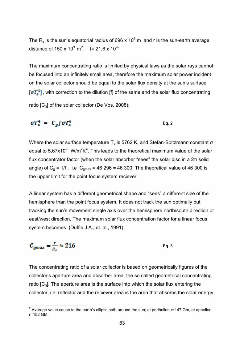
The Rs is the sun’s equatorial radius of 696 x 106 m and r is the sun-earth average
distance of 150 x 109 m2. f= 21,6 x 10⁻⁶
The maximum concentrating ratio is limited by physical laws as the solar rays cannot
be focused into an infinitely small area, therefore the maximum solar power incident
on the solar collector should be equal to the solar flux density at the sun’s surface
[ , with correction to the dilution [f] of the same and the solar flux concentrating
ratio [Cg] of the solar collector (De Vos, 2008):
Eq. 2
Where the solar surface temperature Ts is 5762 K, and Stefan-Boltzmann constant σ
equal to 5,67x10⁻⁸ W/m2K4. This leads to the theoretical maximum value of the solar
flux concentrator factor (when the solar absorber “sees” the solar disc in a 2π solid
angle) of Cg = 1/f , i.e Cgmax = 46 296 ≈ 46 300. The theoretical value of 46 300 is
the upper limit for the point focus system reciever.
A linear system has a different geometrical shape and “sees” a different size of the
hemisphere than the point focus system. It does not track the sun optimally but
tracking the sun’s movement single axis over the hemisphere north/south direction or
east/west direction. The maximum solar flux concentration factor for a linear focus
system becomes (Duffie J.A., et. al., 1991):
Eq. 3
The concentrating ratio of a solar collector is based on geometrically figures of the
collector’s aparture area and absorber area, the so called geometrical concentrating
ratio [Cg]. The aperture area is the surface into which the solar flux entering the
collector, i.e. reflector and the reciever area is the area that absorbs the solar energy.
2 Average value cause to the earth’s elliptic path around the sun; at perihelion r=147 Gm, at aphelion r=152 GM.
83
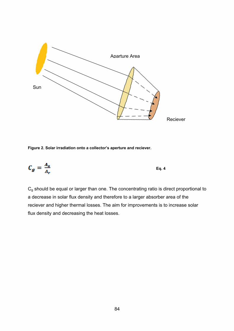
Aparture Area
Figure 2. Solar irradiation onto a collector’s aperture and reciever.
Eq. 4
Cg should be equal or larger than one. The concentrating ratio is direct proportional to
a decrease in solar flux density and therefore to a larger absorber area of the
reciever and higher thermal losses. The aim for improvements is to increase solar
flux density and decreasing the heat losses.
Reciever
Sun
84

2. CSP Power Plants ɳT - Thermal efficiency (Solar thermal cycle)
ɳsteam cycle - Rankine cycle efficiency (Steam cycle)
ɳsolar to electric – CSP plant efficiency (Solar thermal to electric production)
Table 1. Solnova-plant, parabolic trough CSP, Seville, Spain.
Parabolic Trough
# loops troughs/loop
[m2]
Design Data Plant ηT
[%]
Thermal Fluid
[ᵒC]
90 50 MWe 57 Synthetic oil 4 400
300 000
Table 2. Solnova-plant, parabolic trough CSP Power cycle data, Seville, Spain.
Power cycle ηsteam cycle
[%]
Turbine
[˚C/bar]
ηSolar to electricicty
[%]
Power Generated
[GWh/year]
CO2-savings
[ton/year] Rankine 36 Steam 19 114,6 31 200
370/100
Table 3. AndaSol 1-3, parabolic trough CSP, plant data, Spain.
Parabolic Trough
# loops troughs/loop
[m2]
Design Data
Plant
ηT
[%]
Thermal Fluid
[ᵒC]
Storage
[ᵒC]
[Hrs] 90 50 MWe NA Synthetic oil Molten salt 4 400 385
2 000 7,5 Table 4. AndaSol 1-3, parabolic trough CSP, Power cycle data, Spain.
Power cycle ηsteam cycle
[%]
Turbine ηSolar toelectricicty
[%]
Power Generated
[GWh/year]
CO2-savings
[ton/year] Rankine NA Steam NA 180 48003
3 Authors calculation: 450 kWh/12 t CO2
85

Table 5. DISS/INDITEP Superheated steam DSG parabolic trough CSP data.
Parabolic Trough
# loops troughs/loop
[m2]
Design Data
Plant
[MWe]
ηT
[%]
Thermal Fluid
[ᵒC]
[bar] 7 5 65,1 Superheated steam (x=0,85)
10 (8 evaporation
2 superheating)
410
3971 70 Table 6. DISS/INDITEP Superheated steam DSG parabolic trough CSP, power cycle data.
Power cycle ηsteam cycle
[%]
ηSolar to electricicty
[%] Rankine 25,9 16,4
Figure 3. CSP plant for Direct superheated steam generation.
86

Table 7. DISS/INDITEP Saturated steam DSG parabolic trough solar plant.
Parabolic Trough
# loops troughs/loop
[m2]
Design Data
Plant
[MWe]
ηT
[%]
Thermal Fluid
Turbine
[ᵒC]
[bar] 9 5 66,9 Saturated steam 8 280
5106 65
Table 8. DISS/INDITEP Saturated steam DSG parabolic trough solar plant.
Power cycle ηsteam cycle
[%]
ηSolar to electricicty
[%] Rankine 24,9 16,2
Table 9. PS10-plant, Power Tower CSP, Seville, Spain.
Heliostat
# / Area
Tower
Reciever
[m]
Design Data
Reciever
Peak
ηT
[%]
Thermal
Fluid
Thermal
Storage
[hr]/[MWh]
[kg/h]
CO2-saving
[ton/year]
624 / 120 m2 Cavity reciever
55 MWT 257 ᵒ C 40 bars
92 Saturated (Pressurized )
steam
Pressurized steel
accumulator
6700
100,5 650 kW/m2 Water/Steam 1 (50% rate) / 15
100 000
Table 10. PS10-plant, Power Tower, Power cycle, Seville, Spain.
Power
cycle
ηsteam
cycle
[%]
Turbine
[MWnom]
Steamcycle
ηSolar to
electricicty
[%]
Power
Generated
[GWh/year]
Additional
Thermal
Storage
Thermalfluid
Parabolic
trough Rankine 30,7 Steam 250 degC
40 bar 17 24,2 Molten Salt Synthetic oil
11,02 2 Pressures 6,3 kV 50 Hz
8 MWh
87
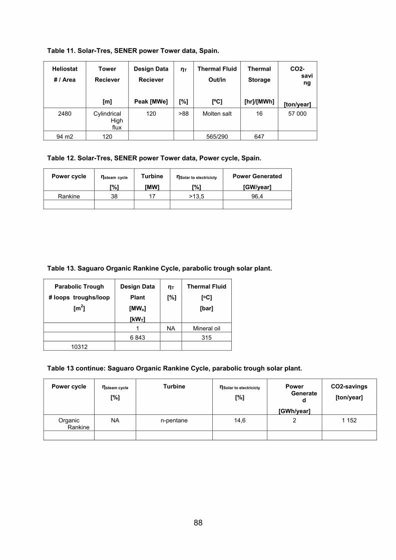
Table 11. Solar-Tres, SENER power Tower data, Spain.
Heliostat
# / Area
Tower
Reciever
[m]
Design Data
Reciever
Peak [MWe]
ηT
[%]
Thermal Fluid
Out/in
[ºC]
Thermal
Storage
[hr]/[MWh]
CO2-saving
[ton/year] 2480 Cylindrical
High flux
120 >88 Molten salt 16 57 000
94 m2 120 565/290 647 Table 12. Solar-Tres, SENER power Tower data, Power cycle, Spain.
Power cycle ηsteam cycle
[%]
Turbine
[MW]
ηSolar to electricicty
[%]
Power Generated
[GW/year] Rankine 38 17 >13,5 96,4
Table 13. Saguaro Organic Rankine Cycle, parabolic trough solar plant.
Parabolic Trough
# loops troughs/loop
[m2]
Design Data
Plant
[MWe]
[kWT]
ηT
[%]
Thermal Fluid
[ᵒC]
[bar]
1 NA Mineral oil 6 843 315
10312 Table 13 continue: Saguaro Organic Rankine Cycle, parabolic trough solar plant.
Power cycle ηsteam cycle
[%]
Turbine ηSolar to electricicty
[%]
Power Generate
d
[GWh/year]
CO2-savings
[ton/year]
Organic Rankine
NA n-pentane 14,6 2 1 152
88

3. TES –media Table 14. Thermal characteristics of TES liquid media. (Pilkington Solar Int., 2000)
Storage material Temperature Average Average Average specific Volume specific
Liquid Media Cold Hot density Heat
conductivity heat capacity heat capacity
˚C ˚C [Kg/m3] [W/mK] [Kj/kgK] [KWh/m3]
Mineral Oil 200 300 770 0,12 2,5 55
Synthetic Oil 250 350 900 0,11 2,3 57
Silicone Oil 300 400 900 0,1 2,1 52
Water 300 400 1000 NA 4,18 116
Salt
Nitrite Salt 250 450 1825 0,57 1,5 152
Nitrate Salt 265 656 1870 0,52 1,6 250
Carbonate Salt 450 850 2100 2 1,8 430
Metal
Na 270 530 850 71 1,3 80
NaK 270 530 855 25 0,9 NA
Table 15. Thermal Characteristics of liquid salt mixtures.
Storage material Transition
Enthalpy change Average
Liquid Media Temperature during melting density
Singel Salts [˚C] [KJ/Kg] [Kg/m3]
Li2CO3 723 607 2110
Na2CO3 858 265 2500
K2CO3 898 200 2300
89

Table 16 Thermal characteristics, TES – solid media. (Pilkington Solar Int., 2000)
Storage material Temp erature Average Average Average specific Volume specific
Solid Media Cold Hot density Heat conductivity Heat capacity Heat capacity
˚C ˚C [Kg/m3] [W/mK] [Kj/kgK] [KWh/m3] Sand rock mineral oil 200 300 1700 1 1,3 60
Reinforced concrete 200 400 2200 1,5 0,5 103,8
High temp. Concrete(DLR) 200 400 2750 1 0,916 140
Castable ceramic (DLR) 200 400 3500 1,4 0,866 168
NaCl (soild) 200 500 2160 7 0,85 150
Cast iron 200 400 7200 37 0,56 160
Cast steel 200 700 7800 40 0,6 450
Silica fire bricks 200 700 1820 1,5 1 150
Magnesia bricks 200 1200 3000 5 1,15 600
Table 17. LHTS – Thermal characteristics of PCM salt mixtures. (Tamme R., 2003)
PCM % of mix. Tmelting ∆Hu
[ºC] [kJ/kg]
NaOH / Na2CO3 x / 7,2 283 340
NaCl / NaOH) 26,8 / x 370 370
NaCl / KCl / LiCl x / 32,4 / 32,8 346 281 NaCl / NaNO3 /Na2SO4 5,7 / 85,5 / x 287 176
NaCl / NaNO3 x / 5,0 284 171
NaCl / NaNO3 5,0 / x 282 212
NaCl / KCl / MgCl2 42,5 / 20,5 / x 385-393 410
KNO3 / NaNO3 10 / x 290 170
KNO3 / KCl x / 4,5 320 150
KNO3 / KBr / KCl x / 4,7 / 7,3 3342 140
NaNO3 310 174
NaNo2 282 212
KNO3 337 116
90

91