OVERVIEW OF BRIDGE PERFORMANCE DURING THE … · placed on the structure due to lateral spreading,...
14
ABSTRACT : The Mw 6.3 February 22, 2011 Christchurch earthquake was centred 10 km south east of central Christchurch on the edge of the city at a depth of 5 km. Peak Ground Accelera- tions (PGA) in the area of Southeast Christchurch were much higher than the design level in the period range of New Zealand road and highway bridges, with exceptional values of vertical acceleration being registered. However, overall most of the bridges performed well, with only eight bridges out of 300 in the area of Christchurch suffering moderate- to-extensive damage. The majority of damage was a result of lateral spreading of the riv- er banks, with only three bridges damaged on non-liquefiable sites. 1 INTRODUCTION The February 22, 2011 moment magnitude (M w ) 6.2 resulted in strong ground shaking in the central and eastern regions of Christchurch, with the majority of significant bridge damage focused in this region. Most of the damage was a result of liquefaction and lateral spreading of the river banks, with very few examples of significant bridge damage on non-liquefiable sites. A number of bridges suffered non-structural damage such as slump- ing of abutment aprons and fracture of deck drainage pipes. Overall, bridges suffered lit- tle structural damage compared to other structures such as residential houses and com- mercial buildings. In spite of the expected damage threshold level being much lower than the estimated bridge response accelerations in the earthquakes, only a few bridges suffered significant visible structural damage as a result of ground shaking. Their typical monolithic con- struction and axial strength also meant older designs were able to resist the axial demands placed on the structure due to lateral spreading, even though they were not specifically designed for these loads. Following the earthquake, the bridge stock was inspected by the network consultants and researchers to establish safety conditions, repairs that were required to enable traffic to flow and document damage. A site walk-over was carried out at each of the inspected 1 University of Canterbury, Christchurch, New Zealand 2 University of Auckland, Auckland, New Zealand 3 CALTRANS, Earthquake Engineering Office, Sacramento, United States 4 University of Buffalo, Buffalo, United States 5 Politecnico di Milano, Milan, Italy OVERVIEW OF BRIDGE PERFORMANCE DURING THE 2011 CHRISTCHURCH EARTHQUAKE by A. Palermo (1) , L. Wotherspoon (2) , L. Hogan (2) , A. Kivell (1) , M. Yashinsky (3) , M. Bruneau (4) & E. Camnasio (5)
Transcript of OVERVIEW OF BRIDGE PERFORMANCE DURING THE … · placed on the structure due to lateral spreading,...

ABSTRACT:
The Mw 6.3 February 22, 2011 Christchurch earthquake was centred 10 km south east of central Christchurch on the edge of the city at a depth of 5 km. Peak Ground Accelera-tions (PGA) in the area of Southeast Christchurch were much higher than the design level in the period range of New Zealand road and highway bridges, with exceptional values of vertical acceleration being registered. However, overall most of the bridges performed well, with only eight bridges out of 300 in the area of Christchurch suffering moderate-to-extensive damage. The majority of damage was a result of lateral spreading of the riv-er banks, with only three bridges damaged on non-liquefiable sites.
1 INTRODUCTION
The February 22, 2011 moment magnitude (Mw) 6.2 resulted in strong ground shaking in the central and eastern regions of Christchurch, with the majority of significant bridge damage focused in this region. Most of the damage was a result of liquefaction and lateral spreading of the river banks, with very few examples of significant bridge damage on non-liquefiable sites. A number of bridges suffered non-structural damage such as slump-ing of abutment aprons and fracture of deck drainage pipes. Overall, bridges suffered lit-tle structural damage compared to other structures such as residential houses and com-mercial buildings.
In spite of the expected damage threshold level being much lower than the estimated
bridge response accelerations in the earthquakes, only a few bridges suffered significant visible structural damage as a result of ground shaking. Their typical monolithic con-struction and axial strength also meant older designs were able to resist the axial demands placed on the structure due to lateral spreading, even though they were not specifically designed for these loads.
Following the earthquake, the bridge stock was inspected by the network consultants
and researchers to establish safety conditions, repairs that were required to enable traffic to flow and document damage. A site walk-over was carried out at each of the inspected
1 University of Canterbury, Christchurch, New Zealand 2 University of Auckland, Auckland, New Zealand 3 CALTRANS, Earthquake Engineering Office, Sacramento, United States 4 University of Buffalo, Buffalo, United States 5 Politecnico di Milano, Milan, Italy
OVERVIEW OF BRIDGE PERFORMANCE DURING THE 2011 CHRISTCHURCH EARTHQUAKE
by A. Palermo(1), L. Wotherspoon(2), L. Hogan(2), A. Kivell(1),
M. Yashinsky(3), M. Bruneau(4) & E. Camnasio(5)

bridges with particular attention focused on checking for evidence of movements at the piers and abutments. On many bridges the most critically loaded components, such as the abutment footings and piles, and pier bases and piles, were covered by water or soil so it was not possible to clearly establish whether there had been damage to these items. How-ever, the extent of gapping between the faces of the piers and abutments and the sur-rounding ground gave some indication of the likelihood of foundation damage. This pa-per presents a summary of observations from the field on a selection of the most severely damaged bridges in the Christchurch area.
2 SEISMIC DEMAND AND SOIL CONDITIONS
The Mw 6.2 February 22, 2011 Christchurch earthquake had an epicenter less than 10km from the Christchurch CBD between Lyttelton and the south eastern edge of the city. The close proximity and shallow depth of this event resulted in higher intensity shaking in Christchurch relative to the Darfield event in September 2010. Further after-shocks occurred during the following months, with one of the strongest, the Mw 6.0 on
June 13, 2011, with an epicenter again on the south eastern edge of the city
Horizontal PGAs were 0.37-0.51g in the Christchurch CBD. Significant vertical accelerations were also registered in this earth-quake. In the Port Hills area, a horizontal PGA of 1.41g was rec-orded near the epicenter at the Heathcote Valley Primary School (HVPS) strong motion station. Strong motion records indicated that most of the bridges within 10km of the Christchurch earth-quake were subjected to horizontal PGA’s of 0.25 to 1.4g (Wood et al., 2011). Acceleration response spectra of typical sites from the Christchurch event are compared with the New Zealand Design Spectra (Transit New Zealand
2004) for site soil class D, 500 year return period. Horizontal acceleration response spec-tra for five strong motion stations (CCCC, HPSC, HVSC, PRPC, SHLC) close to bridges damaged during the Canterbury earthquakes are considered for the comparison. Within the period range of 0-0.8 seconds, a representative period range of many New Zealand road bridges, spectral acceleration values in eastern Christchurch were much higher than the 500 year return period level often used for buildings.
Figure 1 Overview of Christchurch and the surrounding region, indi-cating locations of a selection of damaged bridges and strong motionstations with the maximum recorded horizontal PGA (Google Inc.2011) [Palermo et al. 2011c].

Figure 1indicates the locations of the bridges most severely dam-aged in the Christchurch earth-quake, along with the zone of moderate to severe liquefaction damage. Much of central and eastern Christchurch area was identified as having high lique-faction susceptibility, with most of this area affected by some lev-el of liquefaction following the Christchurch earthquake. Most of the damaged bridges were located along the Avon River, coinciding with the zone of moderate-severe liquefaction. Compared to the Avon River, bridges crossing the Heathcote River suffered much less damage, with much smaller
regions of moderate-severe liquefaction damage even though these areas were closer to the fault rupture than most of the Avon River bridges. Figure 2 confirms the above men-tioned damage trend; the short period spectral accelerations were very high at several of the recorder stations (PRPC, HVSC) close to the fault rupture.
3 CBD BRIDGES
Most of bridges located in the Christchurch central business dis-trict (CBD) are historic structures that marked an important stage in the economic and social devel-opment of an effective transport network laid out in 1850 by the Canterbury Association survey of Christchurch (Figure 3).
The good performance of the
main spans of these bridges was mainly due to their monolithic structure, acting as a stiff strut be-tween river banks affected by lat-eral spreading. No collapses were registered and bridges maintained their vertical load carrying capaci-
Figure 3. Selection of damaged bridges in the CBD area. Clockwise from top left: Colombo Street Bridge; AntiguaStreet Footbridge; Bridge of Remembrance; Moorhouse Ave-nue Overpass.
0.01
0.1
1
0.04 0.4 4
Spec
tral
Res
pons
e A
ccel
arat
ion,
Sa(
g)
Period, T (sec)
CCCCHPSCHVSCPRPCSHLCNZS1170.5
Figure 2 Response spectra of the geometric mean of the horizontalaccelerations at strong motion station in central and eastern Christ-church compared to NZS1170.5 design response spectrum for Christ-church, site subsoil class D for a 500 year return per

ty after the earthquake. Nevertheless, for this same reason the majority of damage was registered at the abutments (flexural cracking) and at the approaches (settlement and spreading).
3.1 Colombo Street Bridge
The Colombo Street Bridge (-43.5271, 172.6366), is a single span steel bridge with concrete pilasters, supported by shallow foundations. Af-ter the Christchurch earthquake there was evidence of severe liquefaction in the bridge vicinity, with lateral spread-ing of both approaches. The lateral displacement of the banks behind the abutment contributed to the large cracks observed in the abutments and their back-rotation. Abutment wall ro-tation was observed on both sides of the bridge, but was more pronounced at the north abutment (Figure 4). The north abutment pilasters also rotated outwards as a result of the lateral spreading pressures on the wingwalls, with vertical cracks in the abutment wall.
Significant damage involved severe
buckling of the arched edge girders both on the upstream and downstream sides of the bridge (Figure 4). The assessed dam-age confirmed a poor detail for the wingwalls, which were not properly connected to the existing structure causing the inevitable buckling of the arches. Because of additional movements and damage resulting from the 13 June 2011 aftershock, the bridge has re-mained closed.
3.2 Antigua Street Footbridge
The Antigua Street Footbridge (-43.5340, 172.6277) comprises riveted steel arched trusses on the outsides of the bridge, connected by cross-bracings and rolled steel channel transoms, which support longitudinal timber stringers, and transverse timber decking.
Signs of liquefaction were visible in the vicinity of the bridge, with ejected sand and
lateral spreading evident approximately 100m south of the footbridge on Antigua Street. Cracks along the river bank leading up to the southern abutment were observed. The movement of the soil led to the shearing off of the abutments where the top chord of the truss connects. Significant damage was evident at the approaches where asphalt has pushed timber decking units out of place. Moreover, the bottom chord of truss has buck-
Figure 4. Colombo Street Bridge. Clockwise from top left: rotation of the abutment [Courtesy of OPUS]; buck-ling of steel arch [Photo by M. Yashinsky]; close up view of the steel arch [Courtesy of OPUS].

led, while there was no buckling in the top chord possibly due to restraint action of tim-ber deck.
Additional damage was observed
after the 13 June 2011 aftershock. The hog in the longitudinal profile of the bridge was approximately 450mm at the centre of the span. Both abutments have back-rotated between 1-1.5 de-grees (Figure 5b), and displaced to-wards the river, with the truss arch compressing. The vertical and diago-nal truss members adjacent to the north eastern abutment have disconnected due to rotation of a low level concrete retaining wall, causing the riveted connection to fail.
The abutment displacement and ro-
tation caused the vertical deflection and hogging of the steel arch truss (Figure 5a). This hogging meant some cross bracing members failed adjacent to more rigid, corroded joints. The shear failure of the concrete wingwalls has caused the supports to the timber footbridge beams to fail (Figure 6a). These supports had very little anchorage into the concrete wingwalls, and would not have required much movement to cause them to fail.
3.3 Bridge of Remembrance
The Bridge of Remembrance (-43.5332, 172.6334), is a single span, stone faced reinforced concrete arch, of variable thickness and skewed in plan. Horizontal earth thrusts are resisted by massive arch thickenings, which extend over the full width of the bridge. This bridge suffered moderate superficial damage as a result of the February 2011 earthquake. However, the Triumphal Arch over the bridge sustained more significant structural damage. In terms of the bridge, reported damage included paving damage at the approaches (Figure 7a), large vertical cracks to all wingwalls (Figure 7b) and widespread cracks near the base of arch, along the full length at base of both parapets and through the buttress of the arch above the east abutment. The width of some of these cracks increased after the 13 June 2011 aftershock.
Figure 5. Antigua Street Footbridge. (a) View under-neath showing hogging [Courtesy of OPUS]; (b) Dam-aged north-eastern abutment [Courtesy of OPUS].
Figure 6. Antigua Street Footbridge. (a) Typical failure of end support to timber footway beams [Courtesy of OPUS]; (b) Typical failure of cross bracing member ad-jacent to corroded joint [Courtesy of OPUS].

The majority of the damage has re-
sulted from settlement of the approach fill, lateral spreading soil pressures re-sulting in deflection and rotation of the wingwalls and possibly the abutments. Minor rotation of all four wingwalls caused cracking of the stone facades. The concrete sections behind the cracked stonework are also likely to have been cracked. This is not consid-ered a major concern at present, as the wingwalls are independent from the main bridge structure and are founded on concrete pads. Cracking of the par-apets may indicate some deflection and hogging of the main arch of the Bridge of Remembrance. However, collapse of this robust structure under earthquake induce soil loading/lateral spreading is highly unlikely.
3.4 Moorhouse Avenue Overpass
Moorhouse Avenue Overbridge (-43.5399, 172.6367) is an eleven span reinforced concrete structure providing grade separation be-tween Moorhouse Avenue and Colombo Street. Moorhouse Ave-nue itself is one of the four ave-nues that encase the CBD of Christchurch City, allowing traf-fic to flow around the CBD.
Significant pier damage devel-
oped during the Christchurch earthquake due to transverse ground shaking. The overall performance of the structure was unsatisfactory, with signif-icant shear cracking and buckling of the piers. This damage affected the vertical load car-rying capacity of the structure along with the lateral capacity. As a result of this damage, the bridge was closed following the February 2010 earthquake for over five weeks while strengthening works were undertaken.
Figure 7. Bridge of Remembrance. (a) Damage to steps on western approach [Courtesy of OPUS]; (b) Damage to north-eastern wingwall [Courtesy of OPUS].
Figure 8. Moorhouse Avenue Overpass. Sketch of the bridge elevation with location of the expansion joints and steel rodlinkages [Palermo et al. 2011a].
ab
EAST WEST
Expansion joint Steel rod linkages
270 m
View from the bottom

The bridge sustained damage to one column near the north-east ap-proach where a deck expansion joint was located. The insertion of steel rod linkages in the deck at the expansion joint at only one side of the bridge in-duced irregularity in the structures transverse response. In fact, with the west and central part of the bridge linked, the bridge pier at the eastern expansion joint suffered extensive displacement demand. The slender-ness of the pier affected the vertical load carrying capacity of the structure along with its lateral capacity. The columns also had widely spaced transverse reinforcement, making the structure susceptible to shear failure (Figure 9a). Observations after the Christchurch event indicated that the damaged columns had started to buckle putting the central span at risk of collapse. In this instance, damage was induced by extensive ground shaking; large transverse horizontal accelerations may have caused a flexural-bucking failure mechanism in the columns.
Due to the higher displacement
demand in the west-central part of the bridge, the deck pounded against the south-west abutment of the bridge causing extensive spalling and bar bucking (Figure 9b). This has occurred as the abutment is also taking some of the longitudinal lateral load of the centre section due to the placement of steel ties.
After initially temporary strengthening works being erected around the failed pier, a multi-span structural steel frame was designed and constructed spanning between the two failed columns. This solution did not provide any additional lateral stability and so the overbridge was not reopened to vehicle traffic until the final temporary solution was im-plemented. To improve the transverse capacity of the damaged structure Opus (consulting engineers) elected to construct dual cross-bracing units at each of the piers. These strad-dled the piers and used doubled up steel sections to act as a diagonal bracing system and is shown in Figure 9c.
Figure 9. Moorhouse Avenue Overpass. (a) Shear failure mechanism of the pier at the expansion joint [Photo by A. Palermo]; (b) Concrete spalling and bar buckling at south-west side abutment [Photo by A. Kivell] [Palermo et al.2011a]; (c) Temporary propping [Photo by G. Whitla].

4 EAST AND SOUTHERN SUBURBS BRIDGES
Damage to bridges outside of the CBD focused on structures spanning the Avon River, which flows from the CBD through the eastern suburbs of Christchurch. Soil conditions and shaking in this region resulted in large set-tlements and lateral spreading due to liquefaction. Liquefaction was not observed to the same ex-tent along the other major wa-terway passing through southern Christchurch, the Heathcote Riv-er, contributing to less damage observed to bridges along this river (Figure 10).
Being the structures very robust
and stiff, damage to road bridges was concentrated to the substructure and approaches, with the superstruc-ture, sustaining mainly pounding damage and minor cracking. Never-theless, while structural damage did not restrict vehicle use following the Christchurch earthquake, many bridges were out of service for a number of hours due to settlement and lateral spreading approach dam-age. Temporary repairs were quickly in place in most cases, but interrup-tion to emergency services at such a critical time raises concerns. Similar-ly, services carried on bridges (wa-ter, electricity) were often incapaci-tated with services not being returned for several weeks.
4.1 Ferrymead Bridge
Ferrymead Bridge (-43.5584, 172.7086) is located at the mouth of the Heathcote River, on the edge of the Avon-Heathcote Estuary, being the primary con-nection between Sumner and Christchurch. This structure was undergoing a major up-grade (deck widening) when the February 2011 earthquake occurred.
Figure 10. Selection of damaged road bridges. Clockwise from top left: Ferrymead Bridge; Bridge Street Bridge; Gayhurst Road Bridge; Avondale Road Bridge; Pages Road Bridge; Fitz-gerald Avenue Bridge.
Figure 11. Ferrymead Bridge. (a) Tilted piers [Courtesy of OPUS]; (b) Close-up view of flexural cracks at the top of the piers [Courtesy of OPUS]; (b) Securing works of Ferrymead Bridge [Courtesy of OPUS].

Ferrymead Bridge was the only bridge along the Heathcote River to suffer significant
damage. Lateral spreading caused significant damage to the new abutment components and temporary construction platforms. The existing structure also sustained damage due to lateral spreading, with permanent rotation and cracking of a number of the piers situat-ed in the estuary (Figure 11a).
Ferrymead Bridge was temporarily repaired with prestressed rods connecting the bot-
tom of the piers to the abutments (Figure 11b). This limited further movements of piers inwards towards the river/estuary which could compromise the overall stability of the bridge. Due to the earthquake damage , heavy vehicle restrictions had been placed on the bridge following the 2011 Christchurch earthquake.
4.2 Bridge Street Bridge
Bridge Street Bridge (-43.5252, 172.7241) crosses the Avon Riv-er near the river estuary. It ser-vices the suburbs of South New Brighton and South Beach providing their primary link to the centre of Christchurch. Most of the damage suffered by the bridge occurred in the 2010 Darfield Earthquake but the dam-age increased in the 2011 Christ-church Earthquake.
The primary cause of damage
was from lateral spreading of the reclaimed embankment soil on which the abutments are located. Situated in an estuary, the under-lying soils were heavily prone to liquefaction and after the onset of shaking, loss of soil stability caused failure and spreading throughout the approach to the bridge (Figure 12). Flow of soil against the wingwall, abutment and through the piles re-sulted in abutment back-rotation due to the restraint provided at the top of the abutments by the superstructure. Transverse translation of the skewed abutments relative to the bridge deck was a result of lateral spreading perpendicular to the bridge axis, and some pounding between the deck and abutments (Figure 12).
Flexural hinging, cracking and spalling was observed in the abutment piles at their
connection to the pile cap caused by both the rotation and the translation of the abutments (Figure 12). Slumping of soil around the abutments due to lateral spreading exposed the
Figure 12. Bridge Street Bridge. Clockwise from top left: Back rotated abutments [Photo by M. Bruneau]; pounding of the deck on the abutment [Photo by A. Kivell]; West approach settlementand temporary repair [Photo by S. White]; plastic hinging in abutment piles of Bridge Street Bridge [Photo by M. Bruneau].

tops of the abutment piles. Hinging at the top of the piles was accompanied by flexural cracking and spalling in the exposed sections of the piles under both abutments. The crack patterns observed on the piles indicate that the piles subjected to bi-directional bending during the earthquake due to the rotation of the abutments and the transverse translation (Figure 12). Crack widths on the west piles were greater than on the east piles suggesting larger deformations. Uncertainty remains with regards to potential plastic hinging below the ground surface.
Major cracking and settlement of the approach pavement and embankments impeded
vehicle access to the bridge (Figure 12). Non-structural components such as guard rails and handrails founded in slumping soil were heavily damaged. The amount of approach settlement at the west end of the bridge was significantly more than observed at the east end. The deck was largely undamaged with damage limited to spalling at the ends due pounding against the abutments.
4.3 Gayhurst Bridge
Gayhurst Road Bridge (-43.5216, 172.6728) is a continuous three span deck bridge supported on wall piers and concrete abutments with wingwalls. The main concern for the site was liquefaction, with previous geotechnical investigations indicat-ing significant liquefaction in a 100-150 year return period seismic event.
In fact, the most significant dam-age was caused by lateral spreading, resulting in movement and loss of re-straint at the abutments, slumping of banks and damage to adjacent roads. The combined effect of the Septem-ber 2010 Darfield and 2011 Christ-church Earthquakes, and the 13 June 2011 aftershock was over one meter of settlement of the northern ap-proach to the bridge.
Lateral spreading resulted in rota-
tion and displacement of the northern abutment backwall and wingwalls (Figure 13a). The top of the wingwalls on both sides of the northern abutment displaced 900mm towards the river rel-ative to the edge of the bridge deck, with lateral movement of 100-150mm at their base. This rotation/translation of the structural element resulted in high flexural stresses in the abutment and eventually cracking, as shown in Figure 13b. The differential settlement of the soil beneath the abutment and the ground shaking may also have contributed to the
Figure 13. Gayhurst Road Bridge. (a) Damaged pier with flexural cracking [Photo by L. Hogan]; (b) Flexural cracks at the north-western wing-wall [Photo by L. Wotherspoon]; (c) Displacement of north-western wing-wall [Photo by L. Wotherspoon].

formation of cracks. The rotation and translation of the wingwalls completely detached them and moved them in front of the backwall (Figure 13c). Conversely, there was little indication of damage to the southern abutment, with no significant displacement or rota-tion accompanying minor cracking.
Lateral spreading exerted a lateral force on the pier base, causing a large moment at
the stiff pier-deck interface, inducing cracking of the pier. A single horizontal crack along one face of a pier, approximately one meter from the deck soffit, developed during the 2010 Darfield event and increased after the February 2011 Christchurch Earthquake (Figure 13a). Liquefaction would have reduced the lateral stiffness of the pier foundation system, allowing rotation of the bottom of the pier towards the centre of the river.
4.4 Fitzgerald Avenue Bridges
The Fitzgerald Avenue Bridges (43.5262, 172.6506) are located on one of four primary arterial corridors that encase the Christchurch central business district. Recent retrofit of the bridges tied the piers and abut-ments to the deck using steel brack-ets.
Following the February, 2011
Christchurch Earthquake the Fitzger-ald Avenue Bridges were closed to traffic for several weeks. Closure was necessary because of severe spreading of the road north of the bridges which developed large fis-sures (Figure 14a). Large amounts of settlement occurred at the bridge ap-proaches primarily on the northern bank; this was accompanied by two directional lateral spreading. The combination of these factors resulted in the back-rotation of the northern bridge abut-ments (Figure 14b). Moderate pounding damage was observed at the ends of the simply supported deck beams, exposing reinforcing steel in some regions.
Rotation of abutments placed high demands on the northern abutment piles. Figure
14c shows the damage to the eastern-most pile of the eastern bridge. Failure occurred in tension with a 30mm crack opening up across the entire section. In some cases, heavy cracking and spalling due to hinging of piles at their connection with the pile cap oc-curred resulting in exposure of prestressing tendons. Below ground pile performance was unable to be determined but it would be expected that differential movements between liquefied and non-liquefied layers caused damage in addition to that at the pile to pile cap connection.
Figure 14. Fitzgerald Avenue Bridge. (a) Damage at the ap-proach of the eastern bridge [Photo by Anton Kivell]; (b) Back rotated abutments [Courtesy of OPUS]; (c) Flexural cracks on the piles [Photo by L. Hogan].

5 STATE HIGHWAY BRIDGES
Few highway bridges have been severely damaged during both Darfield and Christ-church events. The reason of this success is also due to a recent seismic retrofit program which aims to reduce the seismic risk of the National Highway bridges. Several bridges in the Canterbury region have been undergoing some form of seismic retrofitting during the past ten years in particular, after an overall seismic screening of the National High-way network.
One of the most widespread
retrofit programs was undertaken by Transfund New Zealand (now incorporated into NZTA), which saw the installation of tie-rods and steel brackets acting as the transverse shear key between pier-to-deck and deck-to-abutments. Similar devices were installed on bridges on most of the regions highways.
The post-earthquake investiga-
tions have not been in depth enough to ascertain level of de-mand that these devices experi-enced during the seismic shaking. Lateral spreading had been identi-fied as an issue on some key life-line bridges. In some instances, while the bridges remained essen-tially intact, the approach spans partially or totally failed, making access to the bridge ei-ther more difficult or impossible. For example, the twin continuous bridges at the Chaney’s Overpass (-43.4297, 73.9860) on State Highway 1 north of Christchurch (Fig-ure 15, top left) were found to be structurally sound, and tied to their abutment walls to prevent unseating there. However due to liquefaction of the site surrounding the bridge, the approach to the southbound lanes of State Highway 1 settled by a few inches. After a brief closure for inspection, this busy route was reopened with signage reducing the speed to 30 km/h (down from 100km/h) for the safety of motorists.
6 LIFELINES CARRIED BY BRIDGES
Ground shaking and liquefaction/lateral spreading were damaging not only to the bridge substructures but also to pipeline systems crossing bridges. Many services are lo-cated along the longitudinal bridge axis under or within the bridge deck. Lifeline net-works were severely damaged along the Avon River due to extensive liquefaction and lateral spreading. Quite consistently, areas where soil-bridge interaction occurred in lat-eral spreading, pipelines were also damaged. Several pipes were damaged due to a differ-
Figure 15. Overall view of some damaged highway bridges af-ter February 22, 2011. Clockwise from top left: Chaney’s Over-pass [Photo by M. Anagnostopoulou]; Port Hills Overbridge[Courtesy of OPUS]; Horotane Overbridge [Courtesy of OPUS]; Anzac Drive Bridge [Photo by E. Camnasio] [Palermo et al. 2011a].
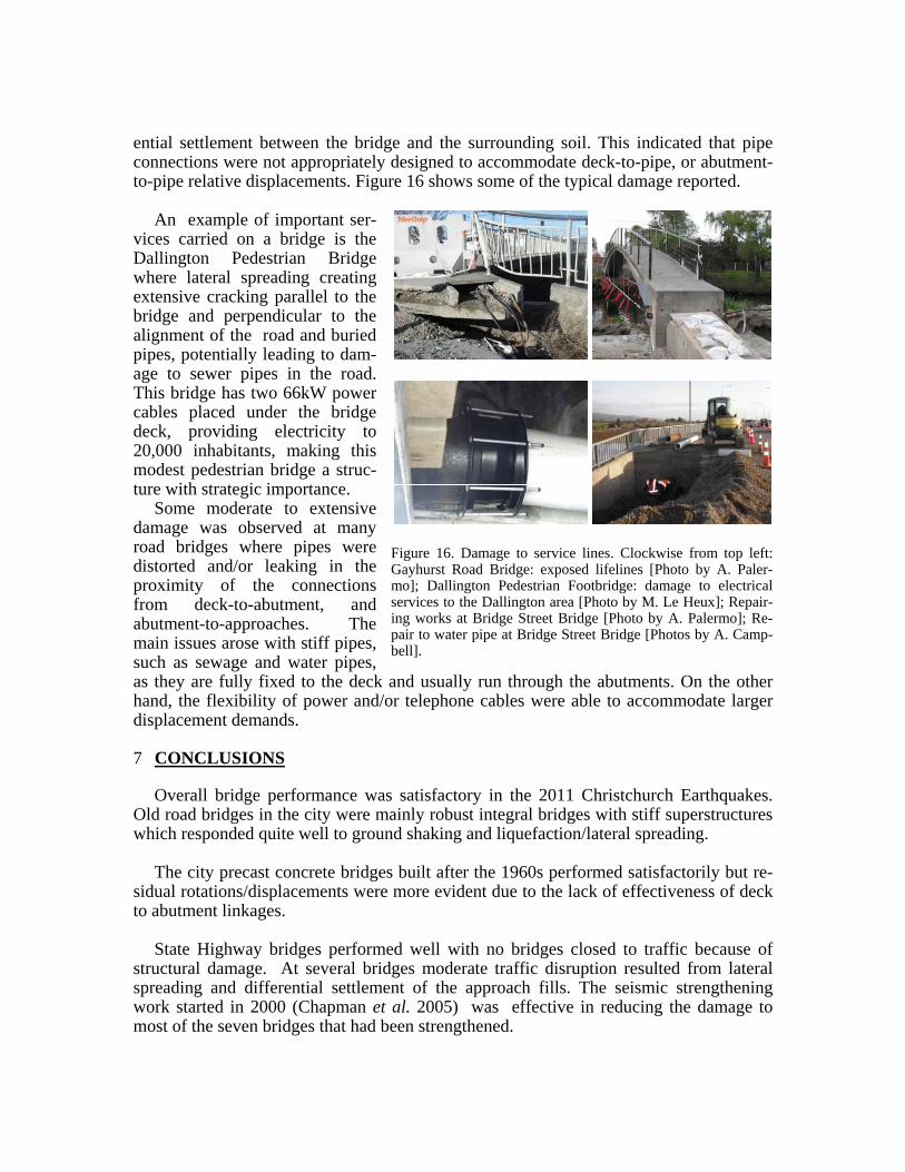
ential settlement between the bridge and the surrounding soil. This indicated that pipe connections were not appropriately designed to accommodate deck-to-pipe, or abutment-to-pipe relative displacements. Figure 16 shows some of the typical damage reported.
An example of important ser-
vices carried on a bridge is the Dallington Pedestrian Bridge where lateral spreading creating extensive cracking parallel to the bridge and perpendicular to the alignment of the road and buried pipes, potentially leading to dam-age to sewer pipes in the road. This bridge has two 66kW power cables placed under the bridge deck, providing electricity to 20,000 inhabitants, making this modest pedestrian bridge a struc-ture with strategic importance.
Some moderate to extensive damage was observed at many road bridges where pipes were distorted and/or leaking in the proximity of the connections from deck-to-abutment, and abutment-to-approaches. The main issues arose with stiff pipes, such as sewage and water pipes, as they are fully fixed to the deck and usually run through the abutments. On the other hand, the flexibility of power and/or telephone cables were able to accommodate larger displacement demands.
7 CONCLUSIONS
Overall bridge performance was satisfactory in the 2011 Christchurch Earthquakes. Old road bridges in the city were mainly robust integral bridges with stiff superstructures which responded quite well to ground shaking and liquefaction/lateral spreading.
The city precast concrete bridges built after the 1960s performed satisfactorily but re-
sidual rotations/displacements were more evident due to the lack of effectiveness of deck to abutment linkages.
State Highway bridges performed well with no bridges closed to traffic because of
structural damage. At several bridges moderate traffic disruption resulted from lateral spreading and differential settlement of the approach fills. The seismic strengthening work started in 2000 (Chapman et al. 2005) was effective in reducing the damage to most of the seven bridges that had been strengthened.
Figure 16. Damage to service lines. Clockwise from top left: Gayhurst Road Bridge: exposed lifelines [Photo by A. Paler-mo]; Dallington Pedestrian Footbridge: damage to electricalservices to the Dallington area [Photo by M. Le Heux]; Repair-ing works at Bridge Street Bridge [Photo by A. Palermo]; Re-pair to water pipe at Bridge Street Bridge [Photos by A. Camp-bell].

Ground shaking and liquefaction/lateral spreading were very damaging at connections
of services to bridges. Many pipeline connections or connecting members fractured caus-ing extensive water leakage and/or pollution of the river crossed. Design guidelines for abutment/pile liquefaction/lateral spreading should be more widely implemented in order to reduce this type damage.
ACKNOWLEDGEMENTS
Authors wish to acknowledge the following institutions and consulting engineering com-panies for the collaboration, technical assistance and data supply: NZTA (John Reyn-olds), Christchurch City Council (Stewart Smith, Lloyd Greenfield, David McNoughton), Opus International Consultants Ltd (Michael Cowan and Anthony Rooke), KiwiRail (Samuel Grave). The support and assistance during the bridge visual inspections of the following researchers is also gratefully acknowledged: Associate Professor. Gregory MacRae (University of Canterbury), Prof. Kazuhiko kawashima (Tokyo Institute of Technology), Prof. Roberto Leon (Georgia Tech). Liam Wotherspoon’s position at the University of Auckland is funded by the Earthquake Commission (EQC). Participation of Mark Yashinsky and Michel Bruneau to this earthquake reconnaissance study was re-spectively funded by the EERI's Learning from Earthquakes Program (which receives support from the U.S. National Science Foundation) and MCEER (University at Buffalo).
REFERENCES
Chapman H.E., Lauder M.K., Wood J.H. (2005). Seismic assessment and retrofitting of New Zealand state highway Bridges. Proc. of the New Zealand Society Earthquake Engineering Conference (NZEES), March, 11-13, 2005, Wairakei (New Zealand), CD-ROM.
GeoNet (2011) “Strong motion FTP site, available from ftp://ftp.geonet.org.nz/strong/processed/Proc/2011/02_Christchurch_mainshock_extended_pass_band/(Accessed August 12, 2011)
GNS Science (2011). http://www.geonet.org.nz/earthquake/ historic-earthquakes/ GeoNet – Historic Earth-quakes. (Accessed September 1, 2011).
Ministry of Works and Development (1978). Highway Bridge Design Brief, CDP 701, New Zealand Minis-try of Works and Development.First published as Rev A in 1971.
NZTA (2003). Bridge Manual, Second Edition, Including Amendments to December 2004. New Zealand Transport Agency, Wellington.
Palermo, A., Wotherspoon, L., Hogan, L., Le Heux, M., Camnasio, E. (2011a). Seismic Performance of Concrete Bridges during Canterbury Earthquakes. Structural Concrete (accepted).
Palermo, A., Wotherspoon, L., Hogan, L., Kivell, A., Yashinsky, M., Bruneau, M. (2011b). Preliminary findings on performance of bridges in the 2011 Christchurch earthquake. Reconnaissance report; web-site: http://www.nzsee.org.nz/ link to Clearing House Darfield and Christchurch.
Palermo, A., Wotherspoon, L., Wood, J., Chapman, H., Scott, A., Hogan, L., Kivell, A., Camnasio, E., Yashinsky, M., Bruneau, M., Chouw, N. (2011c). Lesson learnt from 2011 Christchurch earthquakes: analysis and assessment of bridges. NZSEE Bulletin (in review).
Standards New Zealand,NZS 1170.5:2004. Structural Design Actions. Part 5: Earthquake actions – New Zealand.
Transit New Zealand (1998). Manual for seismic screening of bridges, SM110, Wellington, New Zealand. Transit New Zealand (2004). New Zealand Bridge Design Manual, second edition. Wood, J.H., Chapman, H.E., Brabhaharan, P. (2011). Performance of Highway Structures During the
Darfield and Christchurch Earthquakes. Report to New Zealand Transport Agency. (In preparation).


![unideb.huweb.unideb.hu/uh9v32/011.pdf · the normal cellular isoform of the prion protein, Prpc, to an abnormal scrapie isoform, PrP sc [1 ,2]. Unlike the a-helical Prpc, the protease-resistant](https://static.fdocuments.us/doc/165x107/5f388b704dd641328f7d2f03/the-normal-cellular-isoform-of-the-prion-protein-prpc-to-an-abnormal-scrapie-isoform.jpg)