
Overview - doc.lagout.org Press...Overview Cisco IP Telephony (CIPT) ... Troubleshooting Cisco uOne...
567
1 Overview Cisco IP Telephony (CIPT) is an instructor-led course presented by Cisco Systems, Inc. training partners to their end-user customers. This five-day course focuses on using Cisco CallManager and other IP telephony components connected in local area networks (LANs) and wide area networks (WANs). Upon completion of this training course, you will be able to select, connect, configure, and troubleshoot the various Cisco IP telephony devices. This chapter highlights the course prerequisites and course highlights as well as some administrative issues. It includes the following topics: ■ Objectives ■ Prerequisites ■ General Administration ■ Sources of Information ■ Course Syllabus ■ Graphic Symbols
Transcript of Overview - doc.lagout.org Press...Overview Cisco IP Telephony (CIPT) ... Troubleshooting Cisco uOne...

1
Overview Cisco IP Telephony (CIPT) is an instructor-led course presented by Cisco Systems, Inc. training partners to their end-user customers. This five-day course focuses on using Cisco CallManager and other IP telephony components connected in local area networks (LANs) and wide area networks (WANs).
Upon completion of this training course, you will be able to select, connect, configure, and troubleshoot the various Cisco IP telephony devices.
This chapter highlights the course prerequisites and course highlights as well as some administrative issues. It includes the following topics:
■ Objectives
■ Prerequisites
■ General Administration
■ Sources of Information
■ Course Syllabus
■ Graphic Symbols

1-2 Cisco IP Telephony Copyright 2000, Cisco Systems, Inc.
Course Objectives This section lists the course objectives.
? 2000, Cisco Systems, Inc. www.cisco.com CIPT v2.0? -3
ObjectivesObjectives
Upon completion of this course, you willbe able to perform the following tasks:• Understand CIPT architecture, hardware,
and software• Build three CIPT deployment models• Access the online documentation• Use the tools within the Cisco CallManager
server for troubleshooting
Upon completion of this course, you will be able to perform the following high-level tasks:
■ Given the components of a Cisco IP telephony (CIPT) solution, identify and describe the CIPT architecture, hardware, and software.
■ Given hardware and software of a CIPT network solution, install one of the three recommended CIPT deployment models.
■ Given a Cisco CallManager server, access the online administration guide to configure CIPT components within Cisco CallManager administration.
■ Given an installed Cisco CallManager server, enable and use the tools in the Cisco CallManager server to troubleshoot the CIPT deployment solutions.

Copyright 2000, Cisco Systems, Inc. Cisco IP Telephony Introduction 1-3
? 2000, Cisco Systems, Inc. www.cisco.com CIPT v2.0? -4
IP WAN
PSTN
Rest ofWorld
Telecommuter
Branch Offices
Large Campus(Up to 10,000 users)
A
A
What We Are Going to BuildWhat We Are Going to BuildWith Call
Processing
Without CallProcessing
Primary Inter-Site Voice Path
Secondary Inter-Site Voice Path
XX
The figure shows a high-level overview of a CIPT network that you should be able to build at the end of this class. To accomplish this course goal, you will be taught how to install Cisco CallManager and configure other IP telephony devices in a LAN and WAN environment. This includes the following tasks:
■ Install Cisco CallManager software and supporting services.
■ Cluster Cisco CallManagers to establish redundancy.
■ Select and connect Cisco access gateways for analog, WAN, and PSTN access.
■ Connect and configure digital signal processor (DSP) resources for a CIPT solution.
■ Configure the dial plan architecture to control IP telephony traffic.
■ Build three Cisco IP telephony deployments: isolated Campus LAN, WAN with distributed call processing, and WAN with centralized call processing.
■ Configure IP telephony access through the IP WAN and then the PSTN for backup.
■ Install and configure Cisco uOne for voice messaging for the Cisco IP telephony solution.
Configuration, verification, and troubleshooting are done with Cisco CallManager, Windows 2000 NT Server, and Cisco IOS software.

1-4 Cisco IP Telephony Copyright 2000, Cisco Systems, Inc.
Prerequisites This section lists the course’s prerequisites.
© 2000, Cisco Systems, Inc. www.cisco.com CIPT v2.0—1-5
• Use Windows 2000 to run multiple applications
• Exposure to the Internet or an intranet
• Basic ability with binary and hexadecimal numbering
• Use Windows 2000 to run multiple applications
• Exposure to the Internet or an intranet
• Basic ability with binary and hexadecimal numbering
Interconnecting CiscoNetwork Devices
(ICND)
Interconnecting CiscoNetwork Devices
(ICND)
• Fundamental network device roles
• Understand thelayers of the ISO/OSI reference model
• Fundamental network device roles
• Understand thelayers of the ISO/OSI reference model
PrerequisitesPrerequisites
Cisco Voice over IP –Frame Relay and ATM
(CVOICE)
Cisco Voice over IP –Frame Relay and ATM
(CVOICE)
Cisco IP Telephony (CIPT)
Cisco IP Telephony (CIPT)
Voice Essentials –Basic Telephony and
IP Telephony Concepts
Voice Essentials –Basic Telephony and
IP Telephony Concepts
Building Cisco Remote Access Networks
(BCRAN)
Building Cisco Remote Access Networks
(BCRAN)
To fully benefit from CIPT, you should already possess certain prerequisite skills. The skills are presented in the figure. These skills can be gained from completing the Internetworking Technology Multimedia (ITM) CD-ROM or through work experience. These prerequisites are highlighted in the figure and are outlined below. You should have a working knowledge of the following:
■ Commonly used networking terms and topologies
■ The basic functions of a network protocol
■ Fundamental network device roles (for example, hub, bridge, router, and switch)
■ The Open System Interconnection (OSI) reference model
■ The ability to use Windows 2000 to run multiple applications
■ Exposure to accessing the Internet or an intranet
■ Basic knowledge of binary and hexadecimal numbering
■ Telephony and IP telephony basic concepts
■ Building VoIP networks–gained from the Cisco course, Cisco Voice Over Frame Relay, ATM, and IP v2.0 (CVOICE).

Copyright 2000, Cisco Systems, Inc. Cisco IP Telephony Introduction 1-5

1-6 Cisco IP Telephony Copyright 2000, Cisco Systems, Inc.
Participant Role This section discusses your responsibilities as a student.
? 2000, Cisco Systems, Inc. www.cisco.com CIPT v2.0? -6
Student role• Meet prerequisites
• Introduce yourself
• Ask/answer questions
Participant RoleParticipant Role
To take full advantage of the information presented in this course, you should meet the prerequisites for this class.
Introduce yourself to the instructor and other students who will be working with you during the five days of this course.
You are encouraged to ask any questions relevant to the course materials.
If you have pertinent questions concerning other Cisco features and products not covered in this course, please discuss these topics during breaks or after class, and the instructor will try to answer the questions or direct you to an appropriate information source.

Copyright 2000, Cisco Systems, Inc. Cisco IP Telephony Introduction 1-7
? 2000, Cisco Systems, Inc. www.cisco.com CIPT v2.0? -7
Welcome: PleaseIntroduce YourselfWelcome: Please
Introduce Yourself• Your name and work location
• Your job responsibilities
• Your internetworking experience
• Your objectives for this week
Introduce yourself by stating your name and describing your job function.
Briefly describe your experience with installing and configuring Cisco network devices and with internetworking in general, and also how your experience helped you meet the prerequisites for this course.
You should also state what you expect to learn from this course.

1-8 Cisco IP Telephony Copyright 2000, Cisco Systems, Inc.
General Administration This section highlights miscellaneous administrative tasks that must be addressed.
? 2000, Cisco Systems, Inc. www.cisco.com CIPT v2.0? -8
General AdministrationGeneral Administration
Class-related• Sign-in sheet• Length and times• Participant materials• Attire
Facilities-related• Rest rooms• Site emergency
procedures• Break and lunch
room locations• Communications
The instructor will discuss the administrative issues in detail so you will know exactly what to expect from both the class and facilities. The following items will be discussed:
■ Recording your name on a sign-in sheet
■ The starting and anticipated ending time of each class day
■ What materials you can expect to receive during the class
■ The appropriate attire during class attendance
■ Rest room locations
■ What to do in the event of an emergency
■ Class breaks and lunch facilities
■ How to send and receive telephone, email, and fax messages

Copyright 2000, Cisco Systems, Inc. Cisco IP Telephony Introduction 1-9
Sources of Information This section identifies additional sources of information.
? 2000, Cisco Systems, Inc. www.cisco.com CIPT v2.0? -9
Sources of InformationSources of Information
• www.cisco.com
• CD-ROM
• Cisco Press
Most of the information presented in this course can be found on the Cisco Systems web site or on CD-ROM. These supporting materials are available in HTML format, and as manuals and release notes.
To learn more about the subjects covered in this course, feel free to access the following sources of information:
■ Cisco Documentation CD-ROM or www.cisco.com
■ ITM CD-ROM or www.cisco.com
■ Cisco IOS 12.0 Configuration Guide and Command Reference Guide
■ Catalyst 1900 Series Installation and Configuration Guide
All of these documents can all be found at http://www.cisco.com.

1-10 Cisco IP Telephony Copyright 2000, Cisco Systems, Inc.
Course Syllabus This section discusses the week’s schedule.
© 2000, Cisco Systems, Inc. www.cisco.com CIPT v2.0—1-10
Course SyllabusCourse Syllabus
Cisco IP Telephony Introduction
Introduction to Cisco AVVID
Primary CIPT Components
Understanding DHCP and TFTP
Cisco CallManager
Cisco CallManager Services
Dial Plan Architecture
Cisco Access Gateways
Catalyst Digital Signaling Processor
Resources
Cisco IP Phones
Cisco CallManager Architecture
Campus Infrastructure
WAN Deployment –Distributed Call
Processing
WAN Deployment –Centralized Call
Processing
Troubleshooting
Cisco uOne
Module 1 Module 2 Module 3
The following schedule reflects the recommended structure for this course. This structure allows enough time for your instructor to present the course information to you and for you to work through the laboratory exercises. The exact timing of the subject materials and labs depends on the pace of your specific class.
Module 1, Getting Started with Cisco IP Telephony
The purpose of the module is to introduce you to the training room and the CIPT network environment. This section provides a review of networking fundamentals.
Module 1 includes the following chapters:
■ Chapter 1 Cisco IP Telephony Introduction
■ Chapter 2 Introduction to Cisco AVVID
■ Chapter 3 Primary CIPT Components
■ Chapter 4 Understanding DHCP and TFTP
■ Chapter 5 Cisco CallManager

Copyright 2000, Cisco Systems, Inc. Cisco IP Telephony Introduction 1-11
Module 2, Building a CIPT Campus Solution
The purpose of the module is to introduce you to CIPT fundamentals. You will learn to configure Cisco CallManager and other primary CIPT components in a LAN environment.
Module 2 includes the following chapters:
■ Chapter 6 Cisco CallManager Services
■ Chapter 7 Dial Plan Architecture
■ Chapter 8 Cisco Access Gateways
■ Chapter 9 Catalyst Digital Signaling Processor Provisioning
■ Chapter 10 Cisco IP Phones
■ Chapter 11 Cisco CallManager Architecture
Module 3, Cisco IP Telephony Scalable Options
The purpose of the module is to introduce the student to scalable options of Cisco IP telephony. You will also learn to install and configure Cisco uOne for voice messaging and how to use the IP WAN effectively.
Module 3 includes the following chapters:
■ Chapter 12 Campus Infrastructure
■ Chapter 13 Distributed Call Processing
■ Chapter 14 Centralized Call Processing
■ Chapter 15 Troubleshooting a CIPT Solution
■ Chapter 16 Cisco uOne 4.1E–Corporate

1-12 Cisco IP Telephony Copyright 2000, Cisco Systems, Inc.
Graphic Symbols This section illustrates symbols that are used throughout the course.
? 2000, Cisco Systems, Inc. www.cisco.com CIPT v2.0? -11
WAN loud�
Accessserver
ISDNswitch
Cisco CallManagerServer
Web Server
Graphic SymbolsGraphic Symbols
Bridge Switch Router
Ethernet Serial Line Fast Ethernet
File ServerPersonal computer
Cisco IPPhone
VLAN or Cluster(Color May Vary)
PBX
Circuit SwitchedLine
Multi-layerswitch
DigitalSignal
Processor
Voice GatewayRouter
DSP
These symbols are used in the graphical presentations of this course to represent device or connection types.
Note The addressing schemes and telephone numbers used in this course are reserved and not to be used in the public network. They are used in this course as examples to facilitate learning. When building your network, use only the addresses and telephone numbers assigned by your network designer and service provider.

Copyright 2000, Cisco Systems, Inc. Cisco IP Telephony Introduction 1-13

2
Overview This chapter will provide introductory information about the Cisco Architecture for Voice, Video, and Integrated Data (AVVID) strategy. The Cisco IP Telephony solution is within the AVVID strategy. The architecture delivers an Internet ecosystem, which thrives on open standards, encouraging the development and interoperability of multi-vendor, multi-product solutions.
The following topics are in this chapter:
■ Objectives
■ Cisco AVVID Architecture
■ Convergence
■ End-to-End Architecture
■ IP Telephony Design Goals
■ Deployment Models
■ Written Exercises
■ Summary
■ Review Questions

2-2 Cisco IP Telephony Copyright 2000, Cisco Systems, Inc.
Objectives This section lists the chapter objectives.
? 2000, Cisco Systems, Inc. www.cisco.com CIPT v2.0? -3
ObjectivesObjectives
Upon completion of this chapter, you willbe able to perform the following tasks:• List the four functional groups of the AVVID
architecture• Identify and describe the advantages of a
converged network• Name the three deployment models• Name the maximum number of users
permitted for each of the three deploymentmodels
Upon completion of this chapter you will be able to perform the following tasks:
■ List the four functional groups of the AVVID architecture.
■ Identify and describe the advantages of a converged network.
■ Name the three deployment models.
■ Name the maximum number of users permitted for each of the three deployment models.

Copyright 2000, Cisco Systems, Inc. Introduction to Cisco AVVID 2-3
Cisco AVVID Architecture This section describes the Cisco Architecture for Voice, Video, and Integrated Data (AVVID).
? 2000, Cisco Systems, Inc. www.cisco.com CIPT v2.0? -4
Cisco AVVID SystemArchitecture
Distributed M
anageableD
istributed Manageable
Adaptive O
pen A
daptive Open
CallManagerCallManager DirectoryDirectory Call Admission, Call Routing Call Admission, Call Routing
Call Processing Call Processing
IP PhoneIP PhoneSoftPhoneSoftPhone PCPCVideoVideo
Clients Clients
Applications Applications TAPI, JTAPI, SMDITAPI, JTAPI, SMDI
I
Cisco IPCCCisco IPCCCisco uOneCisco uOne
GatewayGateway RouterRouter SwitchSwitch
Infrastructure Infrastructure Cisco IOS Network Services Cisco IOS Network Services
This figure above represents the four functional groups:
■ Infrastructure
■ Clients
■ Call Processing
■ Applications
The use of open standards and the promotion of multi-vendor collaboration and interoperability are an important benefit of the Cisco AVVID architecture. The architecture creates an environment that fosters competition; this in turn lowers prices for the consumer. It also allows the integration of products from multiple vendors to create a customized solution.
No single vendor can provide a solution that fits all requirements for data, voice, and video. Often specialized applications are designed and implemented only by a single company and need to be integrated with the overall solution. The adoption of open standards creates an ecosystem that actively promotes a model of integration.
2-4 Cisco IP Telephony Copyright 2000, Cisco Systems, Inc.
Convergence This section introduces the concept of converged networks.
? 2000, Cisco Systems, Inc. www.cisco.com CIPT v2.0? -5
Converging to Single Infrastructure
PBX
IP WANCatalyst
BackboneGigabit Ethernet
End User PC100M Ethernet
Voice Network IP Data Network
SwitchesRouters
PSTN
Today eparate Infrastructures
Proprietary digital phones
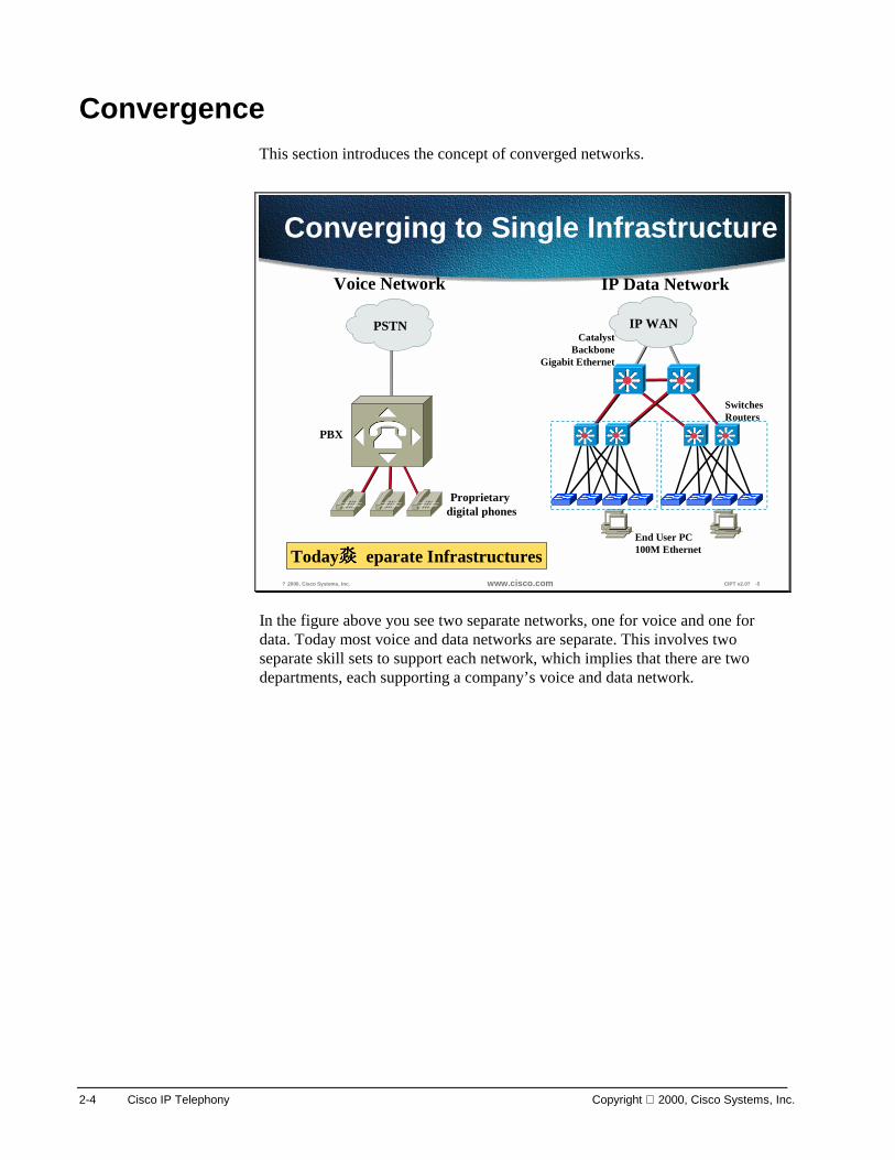
In the figure above you see two separate networks, one for voice and one for data. Today most voice and data networks are separate. This involves two separate skill sets to support each network, which implies that there are two departments, each supporting a company’s voice and data network.
Copyright 2000, Cisco Systems, Inc. Introduction to Cisco AVVID 2-5
© 2000, Cisco Systems, Inc. www.cisco.com CIPT v2.0—2-6
Classic PBX ArchitectureClassic PBX Architecture
PBX Functionality Breaks Down Into Four Categories:
Call Processing
LineConnections
TrunkConnections
Switching
PSTN
TieLinePBX Phones
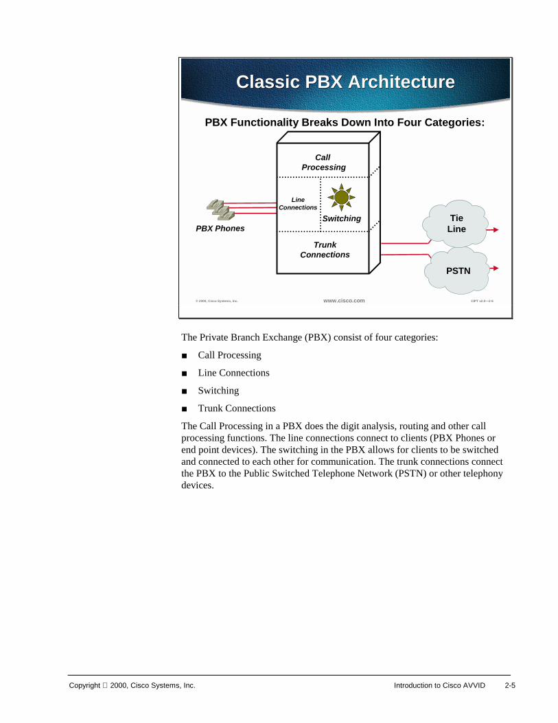
The Private Branch Exchange (PBX) consist of four categories:
■ Call Processing
■ Line Connections
■ Switching
■ Trunk Connections
The Call Processing in a PBX does the digit analysis, routing and other call processing functions. The line connections connect to clients (PBX Phones or end point devices). The switching in the PBX allows for clients to be switched and connected to each other for communication. The trunk connections connect the PBX to the Public Switched Telephone Network (PSTN) or other telephony devices.

2-6 Cisco IP Telephony Copyright 2000, Cisco Systems, Inc.
© 2000, Cisco Systems, Inc. www.cisco.com CIPT v2.0—2-7
IP Telephony ArchitectureIP Telephony Architecture
Call Processing
LineConnections
TrunkConnections
SwitchingIP Phones/Softphone
Clients
MCS 7800 Series Server
Ethernet LAN Switch
Voice Enabled Router or Gateway
IP Telephony Architecture also has four categories:
■ Call Processing
■ Line Connections
■ Switching
■ Trunk Connections
In the IP Telephony architecture, the Cisco CallManager does the call processing of digit analysis, routing and other call processing functions. IP telephony the line connections uses connects to IP Phones, Softphones and other IP telephony clients or endpoints. Ethernet LAN switching products performed the switching functions are by and the trunk connections use voice enabled router and other IP telephony gateways.

Copyright 2000, Cisco Systems, Inc. Introduction to Cisco AVVID 2-7
? 2000, Cisco Systems, Inc. www.cisco.com CIPT v2.0? -6
Choices...
PBX
IP WAN
CatalystBackbone
Gigabit Ethernet
Converged Network(Voice/Video and Data)
SwitchesRouters
IP telephony to the desktop Video desktop
PSTN IP WAN IP WAN
ORConverged Network(Data over Voice)
Now there are choices: a converged network of data over voice or the more preferred voice/video and data. The following advantages are part of the converged network:
■ One network managed by one department
■ Scalable
■ Open Architecture
■ Adaptive and Available

2-8 Cisco IP Telephony Copyright 2000, Cisco Systems, Inc.
Convergence with Cisco AVVID
? 2000, Cisco Systems, Inc. www.cisco.com CIPT v2.0? -7
Gateways
Switches
Routers
Convergence with CiscoAVVID
Convergence with CiscoAVVID
Soft Phone
IP Phones
PCs
Video
IntelligentNetworkServices
IntelligentNetworkServices
Cisco IP Fabric
Clients Infrastructure Applications
Scalable OpenAdaptive Available
MessageMessageServerServer
TelephonyTelephonyAppsApps
ServersServers
DirectoryDirectoryServerServer
Call MgrCall MgrServersServers
MessageMessageServersServers
DirectoryDirectoryServersServers
ContentContentServerServer
ContentContentServersServers
ServiceSupport
Management
Cisco AVVID is an end-to-end architecture that includes three distinct components: infrastructure, clients, and applications. In the three components, there are four functional components (Infrastructure, Clients, Call Processing, Applications). The figure above depicts the components of the architecture.
Infrastructure As with any architecture, Cisco AVVID relies upon a strong and stable foundation. This foundation is built upon the multi-protocol routers and multi-layer LAN switches that are used as building blocks for enterprise networks.
Clients Clients are the end devices that are able to take advantage of the converged IP infrastructure such as, IP phones, PCs, video and soft phones.
Applications The most exciting facet of converged networking is the emerging applications, such as desktop IP telephony, unified messaging and the Cisco IP Contact Center. The converged network offers a framework that permits rapid deployment of these new technologies and innovative applications.

Copyright 2000, Cisco Systems, Inc. Introduction to Cisco AVVID 2-9
End-to-End Architecture This section introduces the Cisco AVVID end-to-end architecture model.
? 2000, Cisco Systems, Inc. www.cisco.com CIPT v2.0? -8
Cisco AVVID from End to EndCisco AVVID from End to End
PSTN
Router/Gateway
CallManager
IP WAN
Headquarters
Branch Office
Telecommuter
Voice Messaging
Primary Inter-site Voice Path
Secondary Inter-site Voice Path
The figure depicts the components of the Cisco AVVID end-to-end architecture model. Ideally the Cisco AVVID end-to-end architecture will not have a Public Switched Telephone Network (PSTN) for backup, only redundant IP WAN networks. For initial deployment and interoperability the IP WAN is the primary Inter-site Voice Path and the PSTN is the secondary Inter-site Voice Path.
The next section describes how the IP WAN and PSTN are used in a Cisco IP telephony network design.

2-10 Cisco IP Telephony Copyright 2000, Cisco Systems, Inc.
IP Telephony Design Goals This section introduces IP telephony design.
© 2000, Cisco Systems, Inc. www.cisco.com CIPT v2.0—2-11
IP Telephony Design GoalsIP Telephony Design Goals
Router plusVoice Gateway
PSTNPSTN
Router/GW
CallManager
IP WANIP WAN
Rest of Rest of thethe
WorldWorldTelecommuterTelecommuter
Branch OfficeBranch Office
X
Regional CenterRegional Center
Router/GWCallManager
HeadquartersHeadquarters
V
V
V
V
A CallManager cluster is located at the headquarters and the Regional Center. The design goal of IP telephony is to have primary connectivity to the regional center, branch office, and telecommuter through the IP WAN and in the future to the rest of the world. The PSTN is for back up use if the IP WAN should go down or bandwidth is unavailable.
The branch office call processing is done at headquarters and phone calls between the branch office and headquarters will be placed over the IP WAN. If the IP WAN goes down, then the calls can use the PSTN to connect using the voice enabled access routers.
With the abundance of IP to the home, now the rest of the world would access the IP WAN to call headquarters.

Copyright 2000, Cisco Systems, Inc. Introduction to Cisco AVVID 2-11
Deployment Models In the AVVID designs based on a CallManager 3.0 environment, three basic deployment models are recommended. This section will give a high level overview of each model and the boundaries in which these designs should be kept. This will provide you with some guidance as to when and why to select a particular design. Subsequent chapters and sections will delve into much more detail of each deployment model. The flow of this section is structured to emulate the labs in this course where each of the deployment models build upon each of these as it progresses.
? 2000, Cisco Systems, Inc. www.cisco.com CIPT v2.0? -10
Three Deployment ModelsThree Deployment Models
• Isolated deployment• Multi-site IP WAN deployments—
(distributed call processing model)• Multi-site IP WAN deployments—
(centralized call processing)
The three deployment models are listed below and are all based on the guidelines of limiting no more than 2500 users per CallManager at any time. These models are:
■ Isolated deployment
■ Multi-site IP WAN deployments—(distributed call processing model)
■ Multi-site IP WAN deployments—(centralized call processing)

2-12 Cisco IP Telephony Copyright 2000, Cisco Systems, Inc.
Individual Campus Deployments
? 2000, Cisco Systems, Inc. www.cisco.com CIPT v2.0? -11
Individual CampusDeployments
Individual CampusDeployments
IP WAN
PSTN
Call Manager
Router/GW
V
LDAPDirectoryMsgMsg
StoreStore
uOneGateserver
Up to 10,000 users per campusCallManager + voice messaging at each siteUp to 6 distributed CallManagers in a clusterRedundancy + equipment will vary with campus size
The above figure is of an individual or isolated deployment. This deployment model must adhere to the following design characteristics:
■ CallManager/CallManager cluster at each campus to provide scalable call control
■ Maximum of 10,000 users per cluster
■ Maximum of 6 CallManagers in a cluster (with specific design requirements)
■ Maximum of 2500 users registered with a CallManager at any time (after failover)
■ Use of PSTN only for networking multiple sites and all external calls
■ DSP (Digital Signal Processor) resources for conferencing at each site
■ Voice/unified messaging components at each site
■ G.711 (uncompressed) for all IP phone calls—80kbps of IP BW per call

Copyright 2000, Cisco Systems, Inc. Introduction to Cisco AVVID 2-13
Multi-site IP WAN (Distributed Call Processing)
? 2000, Cisco Systems, Inc. www.cisco.com CIPT v2.0? -13
Multi-site WAN Deploymentsistributed Call Processing�
Router/GW
IP WAN(Primary Voice Path)
PSTN(Secondary Voice Path)V
Site A
Site B
Site C
IP WANRouter
IP WANRouter
CallManagerV
V
IOS Gatekeeper forAdmission Control
CallManager, Voice Msg + DSP resource at each site10,000 users per site10 sites maximum networked via IP WANAdmission Control .323 v.2 Gatekeeper based
Transparent alternate routing if IP WAN down or lacks resources
CallManager
The above figure is of multi-site WAN deployment that uses Distributed Call Processing and must adhere to the following design characteristics:
■ CallManager/CallManager cluster at each location (10,000 users maximum per site)
■ CallManager clusters are confined to a campus and may not span the WAN
■ Primary inter-site voice path over IP WAN, secondary path over PSTN
■ Transparent use of PSTN if IP WAN unavailable
■ Use of Cisco IOS Gatekeeper for admission control of IP WAN
■ Maximum of 10 sites networked across the IP WAN (hub and spoke topologies)
■ Compressed voice calls supported across the IP WAN
■ DSP resources for conferencing and WAN transcoding at each site
■ Voice/unified messaging components at each site
■ The minimum requirements for voice, video, and data should not exceed 75% of the link/VC’s bandwidth (56kbps is the minimum link speed supported)
■ The customer has a QoS (Quality of Service)/voice enabled network able to support voice transport

2-14 Cisco IP Telephony Copyright 2000, Cisco Systems, Inc.
Multi-site IP WAN (Centralized Call Processing)
? 2000, Cisco Systems, Inc. www.cisco.com CIPT v2.0? -12
Router/GW
IP WAN
CentralizedCallManager
PSTNV
Site A
Site B
Site C
V
IP WANRouter
V
IP WANRouter
Multi-site WAN Deploymentsentralized Call Processing�
Telecommuter
VCallManager, Voice Msg + DSP resource at central siteSupports up to 2500 users totalMax of 3 CallManagers, all IP phones registered to sameAdmission Control mpose limit on # of calls per site (location)
No service if WAN down (unless dial backup)
The above figure is of multi-site WAN deployment that uses centralized call processing that must adhere to the following design characteristics:
■ To support Admission Control only one active CallManager is supported at the central site. May have a second and tertiary CallManager in a cluster of three as long as all IP phones in the cluster are registered to the same Call Manager at any given time. This is called a centralized call processing cluster.
■ Maximum of 2500 users can be supported per centralized call processing cluster in this deployment model (no limit on number of remote sites). May have multiple centralized call processing.
■ Cisco CallManagers of 2500 at a central site that interconnects via H.323.
■ IP phones only at remote sites without a local CallManager.
■ Call admission control mechanism is “bandwidth limits by location” (hub and spoke WAN topology).
■ Compressed voice calls across the IP WAN are supported.
■ Manual use of PSTN if IP WAN is unavailable (get a busy signal and dial PSTN access code).
■ If IP WAN is down then there is no IP phone service unless dial backup exists.
■ Voice/unified messaging and DSP resource components at central site only. The minimum requirements for voice, video, and data should not exceed 75% of the link/VC’s bandwidth (56kbps is the minimum link speed supported).

Copyright 2000, Cisco Systems, Inc. Introduction to Cisco AVVID 2-15
■ Remote sites may use IOS as well as skinny based gateways.
Written Exercise 1: Identifying Functional Groups of Cisco AVVID
Complete the following written exercise to practice what you learned in this chapter.
Objective In this exercise, you will complete the following tasks:
■ Identify the four functional groups of Cisco AVVID
■ Write an example of each functional group
Task: Identify the four functional groups of Cisco AVVID
© 1999, Cisco Systems, Inc. www.cisco.com CIPT—Chapter 12-6
Cisco AVVID System Architecture
Distributed M
anageableD
istributed Manageable
Adaptive Open
Adaptive Open
2.
4.
1.
3.
Example of 1: _______________________________________________
Example of 2: _______________________________________________
Example of 3: _______________________________________________

2-16 Cisco IP Telephony Copyright 2000, Cisco Systems, Inc.
Example of 4: _______________________________________________
Completion Criteria You have completed the exercise when you have filled in the four functional groups of Cisco AVVID in the figure and listed examples of each functional group on the lines below.
Copyright 2000, Cisco Systems, Inc. Introduction to Cisco AVVID 2-17
Written Exercise 2: Identify the three recommended Cisco AVVID Deployments
Complete the following Exercise to practice what you learned in this chapter.
Objective In this Exercise you will identify the three recommended Cisco AVVID deployments.
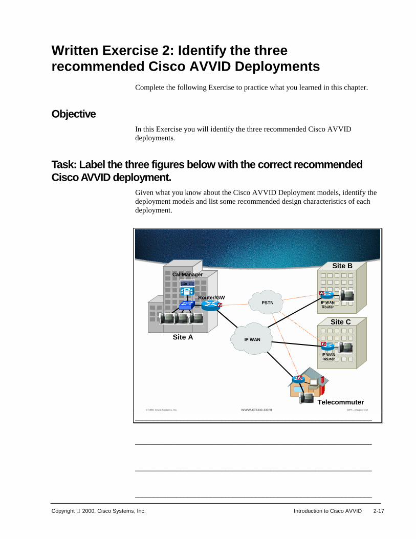
Task: Label the three figures below with the correct recommended Cisco AVVID deployment.
Given what you know about the Cisco AVVID Deployment models, identify the deployment models and list some recommended design characteristics of each deployment.
© 1999, Cisco Systems, Inc. www.cisco.com CIPT—Chapter 2-8
Router/GW
IP WAN
CallManager
PSTNV
Site A
Site B
Site C
V
IP WANRouter
V
IP WANRouter
Telecommuter
V
_______________________________________________________________
_______________________________________________________________
_______________________________________________________________
_______________________________________________________________

2-18 Cisco IP Telephony Copyright 2000, Cisco Systems, Inc.
© 1999, Cisco Systems, Inc. www.cisco.com CIPT—Chapter 2-9
IP WAN
PSTN
Call Manager
Router/GW
V
LDAPDirectoryMsgMsg
StoreStore
uOneGateserver
_______________________________________________________________
_______________________________________________________________
_______________________________________________________________
_______________________________________________________________

Copyright 2000, Cisco Systems, Inc. Introduction to Cisco AVVID 2-19
© 1999, Cisco Systems, Inc. www.cisco.com CIPT—Chapter 2-10
Router/GW
IP WAN(Primary Voice Path)
PSTN(SecondaryVoice Path)
V
Site ASite B
Site C
IP WANRouter
IP WANRouter
CallManagerV
V
IOS Gatekeeper forAdmission Control
CallManager
_______________________________________________________________
_______________________________________________________________
_______________________________________________________________
_______________________________________________________________
Completion Criteria You have completed this exercise when you have identified which Cisco AVVID deployment the figure represents and listed design recommendations for each deployment model.

2-20 Cisco IP Telephony Copyright 2000, Cisco Systems, Inc.
Summary This section summarizes the concepts you learned in this chapter.
? 2000, Cisco Systems, Inc. www.cisco.com CIPT v2.0? -14
SummarySummary
• The Cisco AVVID system architecture hasfour functional groups.
• Convergence of networks has advantages.• Cisco IP telephony is within the Cisco AVVID
system architecture.• There are three deployment models for the
Cisco IP Telephony Solution.
Cisco AVVID architecture has the following four functional groups:
■ Applications—TAPI, JTAPI SMDI; Cisco uOne and Cisco IP Call Center
■ Call processing—call admission, call routing; Cisco CallManager and directory
■ Infrastructure—Cisco IOS network services; gateways, routers, switches
■ Clients—video, softphone, Cisco IP phones, PC
The following advantages are part of a converged network:
■ One network managed by one department
■ Scalable
■ Open
■ Adaptive
■ Available
Cisco IP telephony is within the Cisco AVVID architecture. The Cisco CallManager, Cisco IP phones, and Cisco access gateways are part of the Cisco IP telephony solution. The following deployment models are recommended:
■ Isolated deployment
■ Multi-site IP WAN deployment with centralized call processing

Copyright 2000, Cisco Systems, Inc. Introduction to Cisco AVVID 2-21
■ Multi-site IP WAN deployment with distributed call processing

2-22 Cisco IP Telephony Copyright 2000, Cisco Systems, Inc.
Review Questions Answer the following questions.
? 2000, Cisco Systems, Inc. www.cisco.com CIPT v2.0? -15
Review QuestionsReview Questions
1. Which Cisco AVVID architecturefunctional group does the CiscoCallManager belong to?
2. What is the primary inter-site voicepath in the Cisco AVVID end-to-endarchitecture?
3. What is the maximum number of usersper Cisco CallManager after failover?
Q1) The Cisco AVVID architecture has four functional groups. Which functional group does the Cisco CallManager belong to?
Q2) The Cisco AVVID end-to-end architecture has a primary and secondary inter-site voice path. Which is the primary inter-site voice path?
Q3) In the three deployment models (isolated, multi-site IP WAN centralized call processing, and multi-site IP WAN distributed call processing), what is the maximum number of users a Cisco CallManager can have registered to it after failover?

3
Overview This chapter describes the primary Cisco IP Telephony (CIPT) components at a high level. Each component introduced in this chapter will be discussed later in the course in more detail.
The following topics will be discussed in this chapter:
■ Objectives
■ Visual Objective
■ Call Processing
■ IP Phones
■ DSP Resources
■ PSTN Gateway/Router
■ Voice Messaging
■ Written Exercise
■ Summary
■ Review Questions
3-2 Cisco IP Telephony v.2 Copyright 2000, Cisco Systems, Inc.
Objectives This section lists the chapter objectives.
? 2000, Cisco Systems, Inc. www.cisco.com CIPT v2.0? -3
ObjectivesObjectives
Upon completion of this chapter, you willbe able to perform the following tasks:• Identify and place the primary CIPT
components within a network topology• Define the functions of the primary CIPT
components• Establish a dial tone, given two IP phones, a
switched network, and a Cisco CallManager
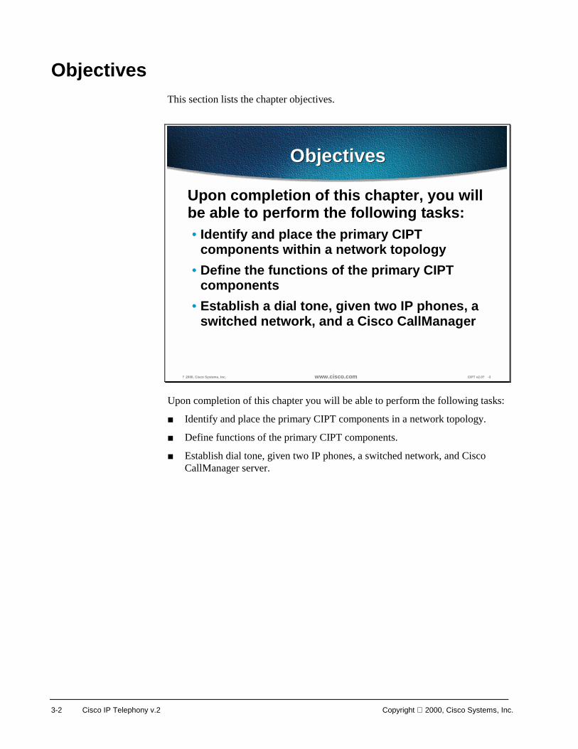
Upon completion of this chapter you will be able to perform the following tasks:
■ Identify and place the primary CIPT components in a network topology.
■ Define functions of the primary CIPT components.
■ Establish dial tone, given two IP phones, a switched network, and Cisco CallManager server.

Copyright 2000, Cisco Systems, Inc. Primary CIPT Components 3-3
Visual Objective This section shows the visual objective of a CIPT solution.
? 2000, Cisco Systems, Inc. www.cisco.com CIPT v2.0? -4
Visual ObjectiveVisual Objective
IP WANCall
Manager
Router/GW
V
LDAPDirectoryMsgMsg
StoreStore
PSTN Gateway/RouterPSTN Gateway/RouterQoS Enabled WAN InfrastructureQoS Enabled WAN Infrastructure
Call ProcessingCall Processing
IP Phones/EndpointsIP Phones/Endpoints
Voice Messaging/Voice Messaging/ApplicationsApplications
Campus Infrastructure/Campus Infrastructure/DSP ResourcesDSP Resources
uOneGateserver
DSP
PSTN
The following sections in this chapter provide a brief description of the primary components of the CIPT solution. Greater detail will be given throughout the course.
3-4 Cisco IP Telephony v.2 Copyright 2000, Cisco Systems, Inc.
? 2000, Cisco Systems, Inc. www.cisco.com CIPT v2.0? -5
IP Telephony ComponentFunctional Breakdown
IP Telephony ComponentFunctional Breakdown
Cisco Call Manager
QoS Enabled L2 Switch
IP Phones/softphones Voice/Unified Messaging
DSP Farm/switchesDSP
SwitchesQoS Enabled L3 Switch
Auto-Attendant/IVR
ClientsClients Call ProcessingCall Processing ApplicationsApplications
IPCC
Call/Contact Center
Voice Enabled InfrastructureVoice Enabled Infrastructure
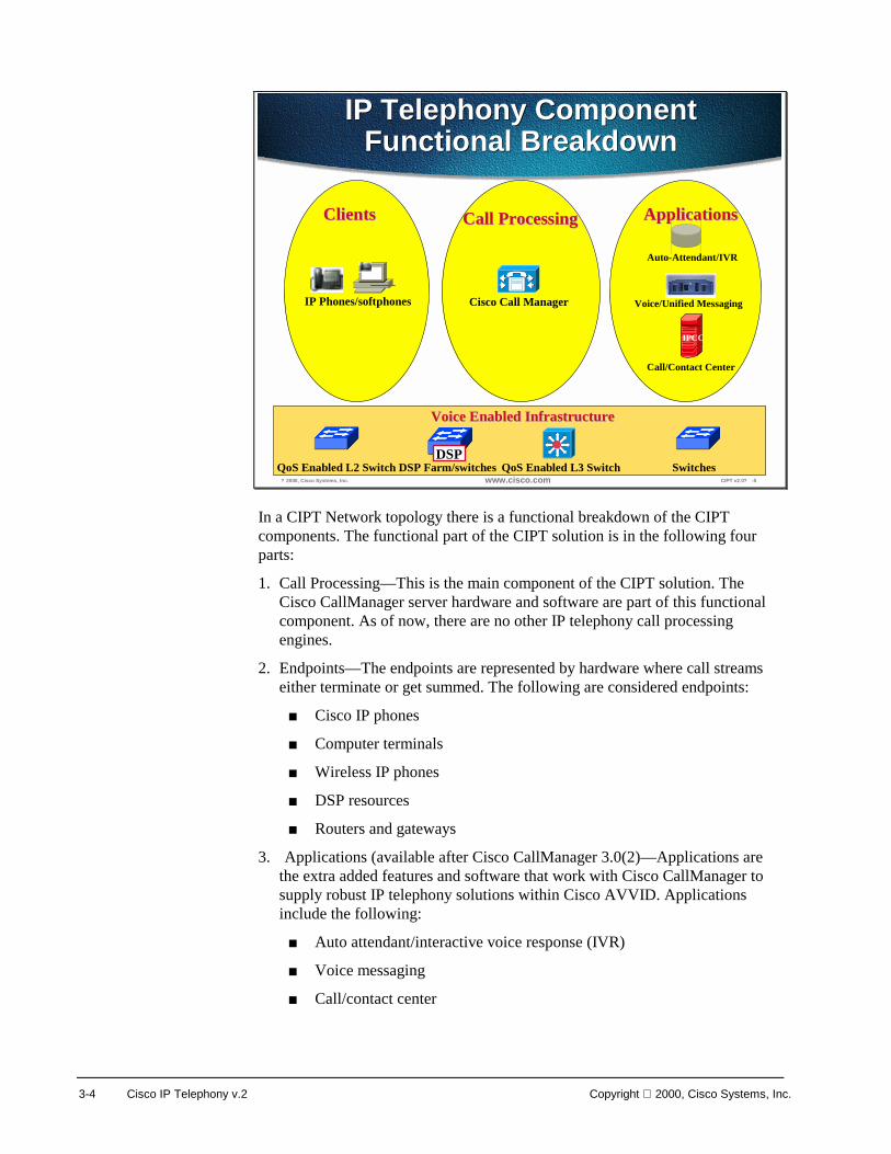
In a CIPT Network topology there is a functional breakdown of the CIPT components. The functional part of the CIPT solution is in the following four parts:
1. Call Processing—This is the main component of the CIPT solution. The Cisco CallManager server hardware and software are part of this functional component. As of now, there are no other IP telephony call processing engines.
2. Endpoints—The endpoints are represented by hardware where call streams either terminate or get summed. The following are considered endpoints:
■ Cisco IP phones
■ Computer terminals
■ Wireless IP phones
■ DSP resources
■ Routers and gateways
3. Applications (available after Cisco CallManager 3.0(2)—Applications are the extra added features and software that work with Cisco CallManager to supply robust IP telephony solutions within Cisco AVVID. Applications include the following:
■ Auto attendant/interactive voice response (IVR)
■ Voice messaging
■ Call/contact center

Copyright 2000, Cisco Systems, Inc. Primary CIPT Components 3-5
4. Voice enabled infrastructure—The voice-enabled infrastructure is the foundation for a reliable and available IP telephony solution. The voice enabled infrastructure includes the following:
■ Quality of Service (QoS) enabled Layer 2 switch
■ QoS enabled Layer 3 switch
■ Router

3-6 Cisco IP Telephony v.2 Copyright 2000, Cisco Systems, Inc.
Call Processing This section describes the components that provide the call processing function within the Cisco IP telephony solution.
? 2000, Cisco Systems, Inc. www.cisco.com CIPT v2.0? -6
Call Processing CallManagerPrimary Functions
Call Processing CallManagerPrimary Functions
• Call processing• Signaling + device control• Features, capabilities and dial plan• Operations administration
maintenance and provisioning(OAM&P)
• Programming interface to externalvoice processing applications
Cisco CallManager provides the call processing functionality in the CIPT solution. The two parts of the Cisco CallManager are the hardware and the software. The Cisco CallManager provides the following functions:
■ Call processing
■ Signaling and device control
■ Features, capabilities, and dial plan
■ Operations administration maintenance and provisioning (OAM&P)
■ Programming interface to external voice processing applications
Copyright 2000, Cisco Systems, Inc. Primary CIPT Components 3-7
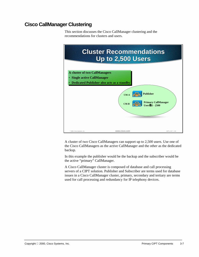
Cisco CallManager Clustering This section discusses the Cisco CallManager clustering and the recommendations for clusters and users.
? 2000, Cisco Systems, Inc. www.cisco.com CIPT v 2.0? 2-10
Cluster RecommendationsUp to 2,500 Users
Cluster RecommendationsUp to 2,500 Users
Publisher
Primary CallManagerUser 1 - 2500
CM-A
CM-B
A cluster of two CallManagers• Single active CallManager• Dedicated Publisher also acts as a standby
A cluster of two CallManagers• Single active CallManager• Dedicated Publisher also acts as a standby
A cluster of two Cisco CallManagers can support up to 2,500 users. Use one of the Cisco CallManagers as the active CallManager and the other as the dedicated backup.
In this example the publisher would be the backup and the subscriber would be the active “primary” CallManager.
A Cisco CallManager cluster is composed of database and call processing servers of a CIPT solution. Publisher and Subscriber are terms used for database issues in a Cisco CallManager cluster, primary, secondary and tertiary are terms used for call processing and redundancy for IP telephony devices.

3-8 Cisco IP Telephony v.2 Copyright 2000, Cisco Systems, Inc.
? 2000, Cisco Systems, Inc. www.cisco.com CIPT v 2.0? 2-11
Cluster RecommendationsUp to 5,000 Users
Cluster RecommendationsUp to 5,000 Users
Publisher
Primary CallManagerUser 1 - 2500
CM-A
CM-B
CM-CPrimary CallManagerUser 2501 - 5000
CM-D Backup for CM_B & CM-C
ClusterCluster
RedundancyGroup
RedundancyGroup
To support up to 5,000 users the recommendation is to use four Cisco CallManagers in one cluster. One Cisco CallManager is the publisher and tertiary Cisco CallManager for redundancy. Two Cisco CallManagers are the primary CallManagers for 2,500 users and both will use the fourth Cisco CallManager as the dedicated backup.
Should Glass House be on a machine by itself? If you have three Cisco CallManagers, the Glass House should be by itself. The name of a machine should not change if SQL Server 7.0 is on it and one database should be in every island of survivability. There is no automated method for moving the Glass House to another machine.
Copyright 2000, Cisco Systems, Inc. Primary CIPT Components 3-9
? 2000, Cisco Systems, Inc. www.cisco.com CIPT v 2.0? 2-12
Cluster RecommendationsUp to 10,000 Users
Cluster RecommendationsUp to 10,000 Users
Primary CallManagerUser 1 - 2500
Primary CallManagerUser 2501 - 5000
Primary CallManagerUser 7501 - 10,000
Primary CallManagerUser 5001 - 7500
ClusterCluster
RedundancyGroups
RedundancyGroups
Publisher
Backup
Backup
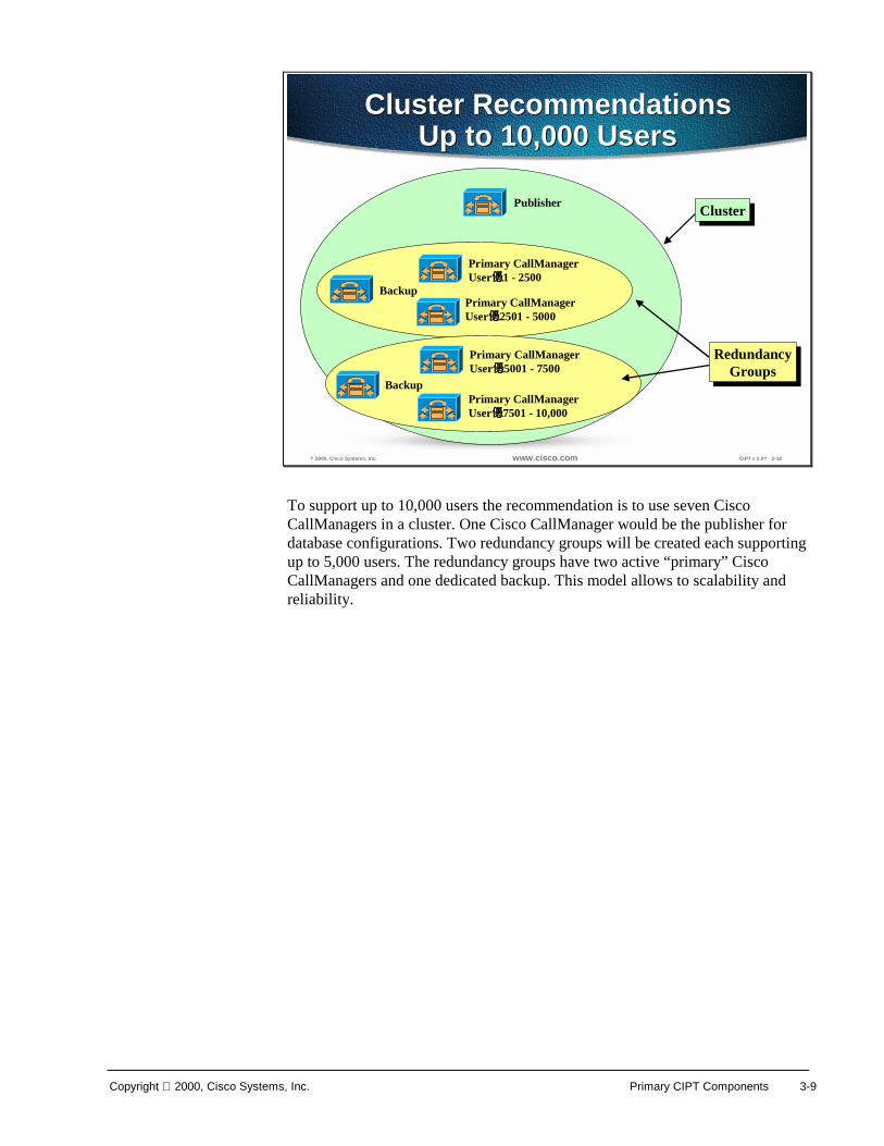
To support up to 10,000 users the recommendation is to use seven Cisco CallManagers in a cluster. One Cisco CallManager would be the publisher for database configurations. Two redundancy groups will be created each supporting up to 5,000 users. The redundancy groups have two active “primary” Cisco CallManagers and one dedicated backup. This model allows to scalability and reliability.
3-10 Cisco IP Telephony v.2 Copyright 2000, Cisco Systems, Inc.
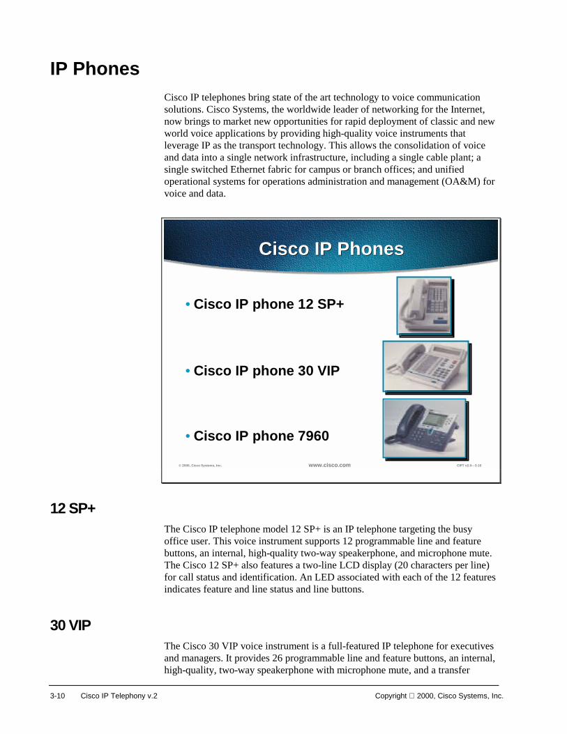
IP Phones Cisco IP telephones bring state of the art technology to voice communication solutions. Cisco Systems, the worldwide leader of networking for the Internet, now brings to market new opportunities for rapid deployment of classic and new world voice applications by providing high-quality voice instruments that leverage IP as the transport technology. This allows the consolidation of voice and data into a single network infrastructure, including a single cable plant; a single switched Ethernet fabric for campus or branch offices; and unified operational systems for operations administration and management (OA&M) for voice and data.
© 2000, Cisco Systems, Inc. www.cisco.com CIPT v2.0—3-10
Cisco IP PhonesCisco IP Phones
• Cisco IP phone 12 SP+
• Cisco IP phone 30 VIP
• Cisco IP phone 7960
12 SP+ The Cisco IP telephone model 12 SP+ is an IP telephone targeting the busy office user. This voice instrument supports 12 programmable line and feature buttons, an internal, high-quality two-way speakerphone, and microphone mute. The Cisco 12 SP+ also features a two-line LCD display (20 characters per line) for call status and identification. An LED associated with each of the 12 features indicates feature and line status and line buttons.
30 VIP The Cisco 30 VIP voice instrument is a full-featured IP telephone for executives and managers. It provides 26 programmable line and feature buttons, an internal, high-quality, two-way speakerphone with microphone mute, and a transfer

Copyright 2000, Cisco Systems, Inc. Primary CIPT Components 3-11
feature button. The 30 VIP also provides a large 40-character LCD display consisting of two lines of 20 characters each. The display provides features such as date and time, calling party name, calling party number, and digits dialed. An LED associated with each of the 30 feature and line buttons provides feature and line status.
Cisco IP Phone 7960 The Cisco IP Phone 7960 includes an information button, six programmable line or feature buttons, and four soft key buttons providing access to features such as additional call detail or access to web-based information, such as stock quotes. The Cisco IP Phone 7960 includes an LCD display, which is used to display call detail and soft key functions.
The Cisco IP Phone 7960 includes two RJ 45 connectors:
■ One connector can be used to connect the phone to a switch that provides 10/100 MBit connectivity and receive power from that switch.
■ Another connector can be used for network connectivity to a desktop device, such as a computer.
Because of the complexity of these new features, Cisco CallManager does not directly control all phone features.

3-12 Cisco IP Telephony v.2 Copyright 2000, Cisco Systems, Inc.
? 2000, Cisco Systems, Inc. www.cisco.com CIPT v2.0? -8
CallManager
IP PhoneRTP Audio Stream (UDP Port 16384+) IP Phone
TCP Signaling(Port 2000)
TCP Signaling(Port 2000)
Off-hook and digit stimulusPlay tone commandsRing command
Off-hook stimulusSetup media stream commandAudio stream established
1
32
4
65
1 3
2 4
6
5
Making a CallIP Telephone to IP Telephone
Making a CallIP Telephone to IP Telephone
IP Phone Signaling Protocols
Skinny station (IP phone)TAPI (soft phone)
IP Phone Signaling Protocols
Skinny station (IP phone)TAPI (soft phone)
When you actually make a telephone call from an IP telephone to an IP telephone, it is a client/server model. The CallManager handles the call control pieces as follows:
1. When you lift the handset on the IP telephone, it goes off-hook.
2. CallManager tells the phone to play a dial tone. The .wav file is in the phone. You enter the digits and dial the number in this case, dialing the phone across the street.
3. Once CallManager has recognized the telephone number, it dials that extension and the phone rings.
4. When the called party answers, the called phone generates an off-hook stimulus to CallManager.
5. CallManager informs the two telephones to set up the media stream between the two phones. Once the audio stream is established, using the Real-Time Transport Protocol (RTP), the CallManager is effectively out of the picture and the two telephones can communicate directly.
6. As of CallManager 2.3, the RTP audio stream uses User Datagram Protocol (UDP) ports 16,384 through 32,767.
This is an important point as these UDP port ranges are synergistic with those used on the Cisco IOS™ gateways. Consequently, IP/RTP priority can now be used to prioritize traffic for both Cisco IOS gateways and the IP telephones.
Note As of Cisco CallManager 2.4, all DTMF from the phone is “out-of-band.”

Copyright 2000, Cisco Systems, Inc. Primary CIPT Components 3-13
DSP Resources The Digital Signaling Processor (DSP) resources can perform conferencing and media termination point (MTP)/transcoding services in addition to their PSTN gateway functionality.
? 2000, Cisco Systems, Inc. www.cisco.com CIPT v2.0? -9
DSP Resources - Purpose andBenefits
V = DSP Farm
G.711 Call LegCompressed Call Leg
VRouter/GW
CallManagerCluster
uOneGateserver
Conferencing
IOS Gatekeeper
V VRouter/GW Router/GW
CallManagerCluster
CallManagerCluster
IP WAN
uOneGateserver
uOneGateserver
Transcoding
Catalyst enabled conferencing is the ability to support voice conferences in hardware. Digital Signaling Processors (DSPs) are use to convert G.711 voice sessions into time-division multiplexing (TDM) streams that can then be “mixed” into a conference call by another DSP.
The transcoding application can either act as a traditional AVVID MTP resource or as a transcoding resource.
■ A traditional AVVID MTP service is the ability to provide supplementary services like hold, transfer, and conference when using gateways that don’t support the H.323.v2 feature of open/close logical channel.
■ Transcoding application is in effect an IP-to-IP voice gateway service. A transcoding node can convert a G.711 voice stream in to a low bite-rate (LBR) compressed voice stream, such as G.729a. This is critical for enabling applications such as IVR, uOne Messaging, and Conference Calls over an IP WAN.

3-14 Cisco IP Telephony v.2 Copyright 2000, Cisco Systems, Inc.
PSTN Gateway/Router The Cisco AVVID telephony solution offers multiple methods of connecting an IP telephony network to the PSTN or legacy PBX and key systems.
? 2000, Cisco Systems, Inc. www.cisco.com CIPT v2.0? -11
Cisco Voice GatewaysCisco Voice Gateways
New
8 Port T1/E1 24 Port FXS (Telco)
Integrated digitaland analog
gateways forCatalyst 6000
family switches
Standalone DigitalGateways DT-24+,
DE-30+
2600
3600
AS5300
7200
1750
AS5800
MC3810
StandaloneAnalog Gateways
AS & ATVG200
There are 20 Cisco voice gateway candidates to choose from. Gateways range from specialized, entry-level stand-alone voice gateways to the high-end, feature rich integrated router and Catalyst gateways.

Copyright 2000, Cisco Systems, Inc. Primary CIPT Components 3-15
? 2000, Cisco Systems, Inc. www.cisco.com CIPT v2.0? -11
Gateway Selection CriteriaGateway Selection Criteria
Standalone vs integrated router/gateway�Cost vs flexibility, functionality, and manageability
Required voice port densitySupport for required PSTN signaling typesGateway protocol
�SGCP (skinny gateway) DT24+, DT 30+, Catalyst 6000 Blades�H.323 (IOS based gateways) 1700/2600/3600/3800/AS5X00/7200�MGCP based gateway VG-200 (can be used as H.323 gateway also)
Support for required WAN interface(s) & QoS
Remote sites likely to add voice ports toexisting voice enabled router
Every gateway selection is made by combining common or core requirements with site and implementation specific features. The three core requirements for an AVVID CIPT gateway are dual tone multifrequency (DTMF) relay capabilities, support for supplementary services and the ability to handle clustered CallManagers. Any gateway selected for a large campus deployment should have the ability to support these features. Additionally, every AVVID CIPT implementation will have it’s own site-specific feature requirements.
There are three types of protocols that are supported. The first are the skinny-gateways. These are a series of digital gateways that include the DT-24+, the DE-30+, and the WS-X6608x1 Catalyst Voice Module. Another type of gateway protocol is traditional H.323. Cisco IOS integrated router gateways use H.323 to communicate with CallManager. The last type of gateway protocol is the new Media Gateway Control Protocol (MGCP). Cisco CallManager uses MGCP to control the new stand-alone gateway, the VG200 analog gateway. Each of these protocols follows a slightly different methodology to provide support for the three core gateway features.
3-16 Cisco IP Telephony v.2 Copyright 2000, Cisco Systems, Inc.
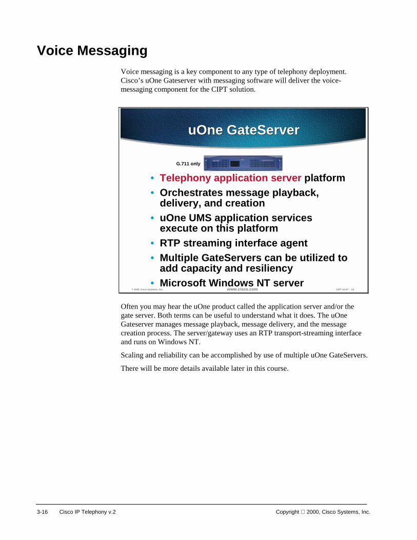
Voice Messaging Voice messaging is a key component to any type of telephony deployment. Cisco’s uOne Gateserver with messaging software will deliver the voice-messaging component for the CIPT solution.
? 2000, Cisco Systems, Inc. www.cisco.com CIPT v2.0? -12
uOne GateServeruOne GateServer
• Telephony application server platform• Orchestrates message playback,
delivery, and creation• uOne UMS application services
execute on this platform• RTP streaming interface agent• Multiple GateServers can be utilized to
add capacity and resiliency• Microsoft Windows NT server
G.711 only
Often you may hear the uOne product called the application server and/or the gate server. Both terms can be useful to understand what it does. The uOne Gateserver manages message playback, message delivery, and the message creation process. The server/gateway uses an RTP transport-streaming interface and runs on Windows NT.
Scaling and reliability can be accomplished by use of multiple uOne GateServers.
There will be more details available later in this course.
Copyright 2000, Cisco Systems, Inc. Primary CIPT Components 3-17
? 2000, Cisco Systems, Inc. www.cisco.com CIPT v2.0? -13
PSTN
Router/GW
CallManager
VDSP
IPWAN
IP Phones
Voice/Unified Messaging Call FlowIP Phone implemented in Gateserver
LDAP DirectoryMessageMessageStoreStore
uOne Gateserver
Applicationserver performsdirectory queryfor called user
2SMTP message
to message store(not in real time)
3
Application serversends MWI N�to CallManager to
illuminate MWI light
4
After 3 rings CallManagersends RTP stream uOne
(in real time)
1
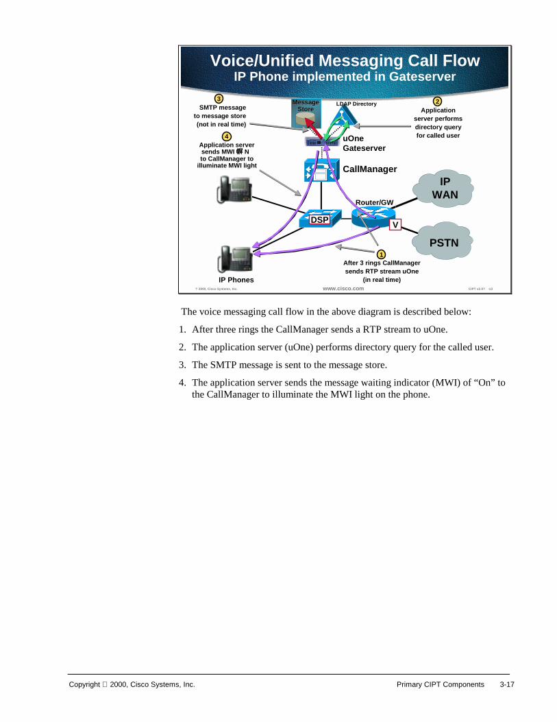
The voice messaging call flow in the above diagram is described below:
1. After three rings the CallManager sends a RTP stream to uOne.
2. The application server (uOne) performs directory query for the called user.
3. The SMTP message is sent to the message store.
4. The application server sends the message waiting indicator (MWI) of “On” to the CallManager to illuminate the MWI light on the phone.

3-18 Cisco IP Telephony v.2 Copyright 2000, Cisco Systems, Inc.
Written Exercise 1: IP Telephony Functional Components
Complete the following exercise to practice what you learned in this chapter.
Objectives In this exercise you will complete the following task: match the functional component with its definition.
Task: Match the functional component with the correct definition. Given what you know about the four functional components of IP Telephony, match the definition to the correct IP Telephony functional component.
1. Represented by hardware where call streams get terminated. The following are examples of this functional component:
– Cisco IP Phones
– Computer terminals
– Wireless IP Phones
2. The foundation for a reliable and available IP Telephony solution. The following are examples of this functional component:
– QoS enabled Layer 2 Switch
– QoS enabled Layer 3 Switch
– Router
3. Extra added features and software that work with Cisco CallManager to supply robust IP Telephony solutions within AVVID. The following are examples of this functional component:
– Web Attendant/Interactive Voice Response (IVR)
– Voice Messaging
– Call/Contact Center
4. The main component of the CIPT solution. The Cisco CallManager server hardware and software are part of this functional component.
_____ 1. Call Processing
_____ 2. Clients
_____ 3. Applications
_____ 4. Voice Enabled Infrastructure

Copyright 2000, Cisco Systems, Inc. Primary CIPT Components 3-19
Completion Criteria You have completed this exercise when you have matched the four functional component definitions to the four functional component headings of IP Telephony.

3-20 Cisco IP Telephony v.2 Copyright 2000, Cisco Systems, Inc.
Summary This section summarizes the concepts you learned in this chapter.
? 2000, Cisco Systems, Inc. www.cisco.com CIPT v2.0? -15
SummarySummary
• Call processing is done by the CiscoCallManager.
• Endpoints include Cisco IP phones, DSPresources, gateways, and routers.
• Cisco uOne is one of the applications in theCIPT solution.
Cisco CallManager is the call processing engine of a Cisco IP telephony solution. In a Cisco IP telephony solution, the endpoints include the Cisco IP phones, DSP resources, gateways and routers. The Cisco IP phones include the 12 SP+, 30 VIP, Cisco IP Phone 7910, and Cisco IP Phone 7960.
Cisco uOne is one of the applications in a Cisco IP telephony solution and the Cisco uOne application is the messaging application providing voice mail services for a Cisco IP telephony solution.

Copyright 2000, Cisco Systems, Inc. Primary CIPT Components 3-21
Review Questions Answer the following questions.
? 2000, Cisco Systems, Inc. www.cisco.com CIPT v2.0? -16
Review QuestionsReview Questions
1. Which functional group do the Cisco IPphones belong to?
2. What are the signaling and devicecontrol functions of the CiscoCallManager?
3. Which services can the DigitalSignaling Processor (DSP) resourcesperform?
Q1) There are four functional groups within the Cisco IP telephony solution. Which functional group are the Cisco IP phones a part of?
Q2) The Cisco CallManager is part of the call processing functional group of the Cisco IP telephony solution. What are the signaling and device control functions that the Cisco CallManager performs?
Q3) In addition to the PTSN gateway functionality, which services can the Digital Signaling Processor (DSP) resources perform?

4
Overview This section provides you with an understanding of how Cisco IP telephony devices can use the optional Windows 2000 server service’s Dynamic Host Configuration Protocol (DHCP) and Domain Name System (DNS) to communicate with the Cisco CallManager. You will also understand the relationship between the Cisco IP phones and Cisco Access gateways and the Trivial File Transfer Protocol (TFTP) server.
This chapter includes the following topics:
■ Objectives
■ Understanding DHCP and TFTP
■ Understanding TFTP
■ Understanding Microsoft DHCP Options
■ Summary
■ Review Questions

4-2 Cisco IP Telephony Copyright 2000, Cisco Systems, Inc.
Objectives This section lists the chapter objectives.
? 2000, Cisco Systems, Inc. www.cisco.com CIPT v2.0? -3
ObjectivesObjectives
Upon completion of this chapter, you will beable to perform the following tasks:• Identify and chart the flow of a CIPT device
with DHCP, DNS and TFTP running• Describe the DHCP and DNS options within
Windows 2000• Configure TFTP servers for use with Cisco IP
phones and Cisco access gateways
Upon completion of this chapter, you will be able to complete the following tasks:
■ Identify and chart the flow of a CIPT device with DHCP, DNS, and TFTP.
■ Describe and identify the DHCP and DNS options within Windows 2000.
■ Configure TFTP servers for use with Cisco IP phones and Cisco access gateways.
Copyright 2000, Cisco Systems, Inc. Understanding DHCP and TFTP 4-3
Understanding DHCP and TFTP This section describes how you use DHCP and TFTP.
DHCP (Dynamic Host Configuration Protocol) service is a client/server system available with the Windows NT server. DHCP automatically assigns IP addresses to devices whenever you plug them in. For example, this allows you to connect multiple phones anywhere on the IP network and DHCP automatically assigns IP addresses to them.
By default, Cisco IP phones are DHCP-enabled. If you are not using DHCP, you need to disable DHCP on the phone and manually assign it an IP address.
When the devices connect to the DHCP server, the DHCP server provides them with the default TFTP server information. The IP phones and gateways must access the Trivial File Transfer Protocol (TFTP) server to retrieve their configuration file.
? 2000, Cisco Systems, Inc. www.cisco.com CIPT v2.0? -4
DHCP and TFTP WorkingTogether
DHCP and TFTP WorkingTogether
1
3
2
4
5
DHCPDNS
CallManagerTFTP
13
245
*Use configuration in Flash after timeout
Useanyone
Get IP address, mask, DNS, and so forth.• Static or DHCP
Get TFTP server address• Static address• Option 150 (single IP address)• Option 66 (first IP address or DNS name)• Look up CiscoCM1.your.domain
Get configuration from CallManager TFTP*• List of up to three CallManagers• Region info and keyboard template• Version of code to run
Get new code (one time only)Register with CallManager
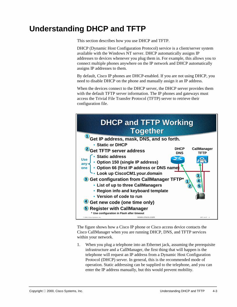
The figure shows how a Cisco IP phone or Cisco access device contacts the Cisco CallManager when you are running DHCP, DNS, and TFTP services within your network.
1. When you plug a telephone into an Ethernet jack, assuming the prerequisite infrastructure and a CallManager, the first thing that will happen is the telephone will request an IP address from a Dynamic Host Configuration Protocol (DHCP) server. In general, this is the recommended mode of operation. Static addressing can be supplied to the telephone, and you can enter the IP address manually, but this would prevent mobility.

4-4 Cisco IP Telephony Copyright 2000, Cisco Systems, Inc.
2. As part of that DHCP request, when an IP address is supplied to the telephone, it is also possible to supply the address of the TFTP server, or the CallManager from which the telephone will get its configuration. Once again, the TFTP server address could be specified manually but this would limit adds, moves, and changes and remove some of the benefits. This TFTP server address can be given in one of two forms: either Option 150, which is what you would recommend, or Option 66 or the Bootstrap Protocol (BOOTP), which you may be familiar with. BOOTP would not be recommended, although it is a viable option, since it is already in general use by other devices already.
3. Once that address has been given, the telephone itself will register with the CallManager and download its configuration, which can contain a list of up to five CallManagers that the telephone can use for call control. This creates an extremely resilient system. You will get your region information and also the features or functionality that each of your keys will produce for you.
4. You also receive any new code you are to run. If, for example, the firmware or the code that each telephone runs is changed, this can be added to the CallManager. Once restarted, each telephone will automatically reload that code, once again making maintenance very simple. The telephones can be configured to auto register.
5. An administrator rolling out the phones would plug each one in and then assign a number. New entries will appear by Media Access Control (MAC) address, which is how the CallManager ties the actual instrument to a telephone number. An alternate, not the normal operation, would occur when you plug in the telephone; CallManager would automatically give that telephone a line number, however, this would make things like directories very difficult to set up.
Copyright 2000, Cisco Systems, Inc. Understanding DHCP and TFTP 4-5
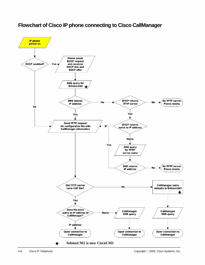
Understanding TFTP This section describes how to connect a Cisco IP phone to CallManager.
The phones and gateways have an order of preference that they use for selecting the address of the TFTP server. If it receives conflicting or confusing information from the DHCP server, the phone uses the following sequence to determine what information is valid.
1. You can configure the phone (but not a gateway) with a TFTP server address through keypad configuration.
■ This address overrides any TFTP address sent by the DHCP server.
■ The phone always tries to resolve the DNS name CiscoCM1.
2. If this name is resolved, then this information overrides all information sent by the DHCP server. It is not necessary to name the TFTP server CiscoCM1, but you must enter a DNS name record to associate CiscoCM1 with the address or name of the TFTP server.
3. The phone uses the value of Next-Server in the boot processes—This DHCP configuration parameter has traditionally been used as the address of the TFTP server. When configuring BootP servers, this field is typically referred to as the address of the TFTP server. This information is returned in the siaddr field of the DHCP header. You should always use this option, if available, because some DHCP servers will place their own IP address in this field when it is not configured.
4. The phone uses the site-specific option 150—This option resolves the issue that Microsoft 2000 or NT servers do not allow the Next-Server configuration parameter. The 2000 or NT servers allow access to the Next-Server parameter only when IP address are statically assigned.
5. The phone also accepts the Optional Server Name parameter. This DHCP configuration parameter is the DNS name of a TFTP server. Currently only a DNS name can be configured in this parameter. A dotted decimal IP address should not be used.
6. The phone also accepts the 066 option, which is the name of the boot server.
■ Option 066 is normally used to replace the name field when option overloading occurs. It can be used on Windows 2000 or NT DHCP servers and functions like the 150 option. This name field can contain a DNS name or a dotted decimal IP address.
■ The 066 option should NOT be used with the 150 option. If they are sent together, then the phone prefers the IP address to the name given by the 066 option. However, if both a dotted decimal IP address and a 150 option are sent, then order of preference is dependent on the order that they appear in the option list. The phone chooses the last item in the option list. To reiterate, option 066 and option 150 are mutually exclusive.
See the flowchart on the following page.
4-6 Cisco IP Telephony Copyright 2000, Cisco Systems, Inc.
Flowchart of Cisco IP phone connecting to Cisco CallManager
SelsiusCM1 is now CiscoCM1

Copyright 2000, Cisco Systems, Inc. Understanding DHCP and TFTP 4-7
Understanding Microsoft DHCP Options This section describes the Microsoft DHCP options.
? 2000, Cisco Systems, Inc. www.cisco.com CIPT v2.0? -6
Microsoft DHCP OptionsMicrosoft DHCP Options
Understanding Microsoft DHCP options:• TFTP server (150 boot server IP address or
066 boot server host name)• Default gateway (003 router)
Additionally, you may need:• DNS server (006 DNS servers ptional)
• Domain name (015 Domain Name ptional)
Note: Use DNS and domain name only if needed
Understanding Microsoft DHCP options:
■ TFTP Server (066 boot server host name or 150 boot server IP address)
■ Default gateway (003 router)
Additionally, you may need:
■ DNS server (006 DNS servers—optional, use only if needed)
■ Domain name (015 domain name—optional, use only if needed)

4-8 Cisco IP Telephony Copyright 2000, Cisco Systems, Inc.
© 2000, Cisco Systems, Inc. www.cisco.com CIPT v2.0—4-7
Creating and Defining DHCP Scope
Creating and Defining DHCP Scope
A DHCP scope must be defined for CIPT device registration. The path to DHCP is Start>Programs>Administrative Tools>DHCP. To create and define a new scope, select the server you are on and select “New Scope” using a right mouse click. DHCP scopes can be created, defined or deleted from this DHCP window.
Copyright 2000, Cisco Systems, Inc. Understanding DHCP and TFTP 4-9
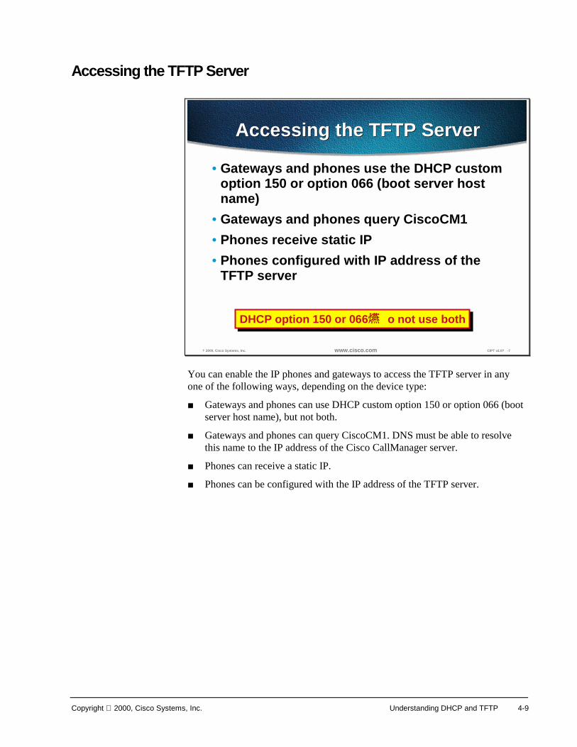
Accessing the TFTP Server
? 2000, Cisco Systems, Inc. www.cisco.com CIPT v2.0? -7
Accessing the TFTP ServerAccessing the TFTP Server
• Gateways and phones use the DHCP customoption 150 or option 066 (boot server hostname)
• Gateways and phones query CiscoCM1• Phones receive static IP• Phones configured with IP address of the
TFTP server
DHCP option 150 or 066 o not use bothDHCP option 150 or 066 o not use both
You can enable the IP phones and gateways to access the TFTP server in any one of the following ways, depending on the device type:
■ Gateways and phones can use DHCP custom option 150 or option 066 (boot server host name), but not both.
■ Gateways and phones can query CiscoCM1. DNS must be able to resolve this name to the IP address of the Cisco CallManager server.
■ Phones can receive a static IP.
■ Phones can be configured with the IP address of the TFTP server.

4-10 Cisco IP Telephony Copyright 2000, Cisco Systems, Inc.
Summary This section summarizes the concepts you learned in this chapter.
? 2000, Cisco Systems, Inc. www.cisco.com CIPT v2.0? -8
SummarySummary
• Cisco CallManager, DHCP TFTP, and DNSwork together.
• The TFTP default server name is CiscoCM1.• Phones and gateways have an order of
preference they use for selecting the addressof the TFTP.
DHCP automatically assigns IP addresses to devices whenever you plug them in and by default the Cisco IP phones are DHCP-enabled. Cisco IP telephony devices retrieve their configuration file from the TFTP server. DNS enables devices to resolve IP addresses of DHCP and TFTP using names rather than IP addresses.
The Cisco IP telephony devices attempt to TFTP to the default server name “CiscoCM1.” If an IP address or name is not received, the default name “CiscoCM1” is used.

Copyright 2000, Cisco Systems, Inc. Understanding DHCP and TFTP 4-11
Review Questions Answer the following questions.
? 2000, Cisco Systems, Inc. www.cisco.com CIPT v2.0? -9
Review QuestionsReview Questions
1. What do the Cisco IP telephony devicesquery to get their IP address?
2. What do Cisco IP telephony devicesquery to get their configuration file?
3. Which DHCP options can you use toaccess the TFTP server?
Q1) The Cisco IP telephony devices (IP phones and gateways) need an IP address. What do the devices query to get an IP address?
Q2) In order for Cisco IP telephony devices to register with the Cisco CallManager, they must have configuration files. What do the devices query to get their configuration files?
Q3) Cisco IP telephony devices need to access the TFTP server. Which DHCP options are used to notify the devices where the TFTP server is located?

5
Overview Cisco CallManager on the Cisco Media Convergence Server (MCS) is a network business communications system providing high-quality telephony over IP networks. Cisco CallManager and the MCS enable the conversion of conventional, proprietary circuit-switched telecommunication systems to multi-service open LAN systems.
The following topics are discussed in this chapter:
■ Objectives
■ Primary Functions
■ Hardware
■ Cisco CallManager Administration
■ Installable Components
■ Installation
■ Laboratory Exercises
■ Summary
■ Review Questions
5-2 Cisco IP Telephony Copyright 2000, Cisco Systems, Inc.
Objectives This section lists the chapter objectives.
? 2000, Cisco Systems, Inc. www.cisco.com CIPTv2.0? -3
ObjectivesObjectives
Upon completion of this chapter, you willbe able to perform the following tasks:• Identify the hardware components and
operating system requirements of the MCS-7830 and MCS-7835
• Describe and identify CallManager clusterrequirements and guidelines
• Configure system parameters in the CiscoCallManager software that will enable dial toneto a Cisco IP phone when connected
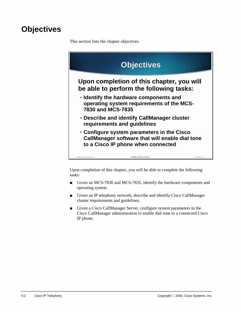
Upon completion of this chapter, you will be able to complete the following tasks:
■ Given an MCS-7830 and MCS-7835, identify the hardware components and operating system.
■ Given an IP telephony network, describe and identify Cisco CallManager cluster requirements and guidelines.
■ Given a Cisco CallManager Server, configure system parameters in the Cisco CallManager administration to enable dial tone to a connected Cisco IP phone.

Copyright 2000, Cisco Systems, Inc. Cisco CallManager 5-3
Primary Functions This section describes the primary functions of the CallManager.
? 2000, Cisco Systems, Inc. www.cisco.com CIPTv2.0? -5
Primary FunctionsPrimary Functions
• Call processing• Signaling and device Control• Features, capabilities, and dial plan• Operations administration maintenance and
provisioning (OAM&P)• Programming interface to external voice
processing applications
The primary functions of the Cisco CallManager are the following:
■ Call processing (digit analysis and resolution)
■ Signaling and device control
■ Features, capabilities, and dial plan
■ Operations administration maintenance and provisioning (OAM&P)
■ Programming interface to external voice processing applications
Note Some functions may be covered later in this course, because they work in conjunction with other CIPT components.
Cisco CallManager extends enterprise telephony features and functions to packet telephony network devices such as IP phones, software phones, and Voice over IP (VoIP) gateways.
Supplementary and enhanced services such as hold, transfer, forward, conference, multiple line appearances, automatic route selection, speed dial, last-number redial, and other features are extended by Cisco CallManager to IP phones and gateways. Because CallManager is a software application, enhancing Cisco CallManager is a matter of upgrading software, thereby avoiding expensive hardware upgrade costs. Further, Cisco CallManager configuration

5-4 Cisco IP Telephony Copyright 2000, Cisco Systems, Inc.
allows all phones, gateways, and applications to be distributed across a routable IP network, providing a single, distributed, virtual telephony network.

Copyright 2000, Cisco Systems, Inc. Cisco CallManager 5-5
? 2000, Cisco Systems, Inc. www.cisco.com CIPTv2.0? -6
PSTNRouter/GW
CallManager
VDSP
IPWAN
LDAPDirectoryMessageMessage
StoreStore
IP Phone B
Call Processing
1-CallSetup
2-E.164 lookup
3-CallSetup
4-Ring
4-Ringback
5-Offhook
6-ConnectRTP Stream
uOne Gateserver
IP Phone A
Cisco CallManager does the call processing in an IP telephony network. The following describes how the call processing works:
1. Call setup request, which includes off-hook signaling, digit collection, and digit analysis, from phone A
2. E.164 lookup for phone B
3. Call setup request sent to phone B
4. Ring played to phone B and ring back played to phone A
5. Phone B goes “off-hook”
6. Connect RTP stream between phone A and B

5-6 Cisco IP Telephony Copyright 2000, Cisco Systems, Inc.
Hardware This section describes the Media Convergence Sever 7800 series hardware platforms.
? 2000, Cisco Systems, Inc. www.cisco.com CIPTv2.0? -8
MCS-7800 Server Family
MCS-7822MCS-7822 MCS-7830MCS-7830
No Picture,yet.
No Picture,yet.
MCS-7835MCS-7835
The Media Convergence Server 7800 series (MCS-7800) are the supported hardware platforms for Cisco CallManager that provide for scalable hardware architecture:
■ The Cisco MCS-7822 is intended to be a pilot-test platform as a standalone server, or a production-level server when two MCS-7822s are deployed in a primary/backup role.
■ The Cisco MCS-7830 is an integral part of a complete, scalable architecture for a new generation of high-quality IP voice solutions that run on the enterprise data network.
■ The MCS-7835 is engineered to run a variety of Cisco AVVID applications, such as Cisco CallManager and Cisco Unified Open Network Exchange voice messaging.
Note No third-party software applications to run on a Media Convergence Server series platforms.

Copyright 2000, Cisco Systems, Inc. Cisco CallManager 5-7
MCS-7822
? 2000, Cisco Systems, Inc. www.cisco.com CIPTv2.0? -9
MCS-7822MCS-7822
Compaq Prosignia 720550MHz Pentium III Processor512 MB RamSingle 9.1 GB Hard Drive
Compaq Prosignia 720550MHz Pentium III Processor512 MB RamSingle 9.1 GB Hard Drive
Performance The Cisco MCS-7822 includes Intel's next-generation Pentium III, delivers 550-MHz performance, and ships with 512 MB of Error-Correcting Code (ECC) RAM, extending the high performance you will require to roll out IP telephony applications.
Availability In a single-server configuration, the Cisco MCS-7822 lacks the redundant components that most customers will desire to run the MCS-7822 in a production environment. Two MCS-7822s operating in a "primary" and "secondary" mode will provide a robust fail-over mechanism so customers can run in a production environment. As part of its configuration, each IP telephone will store the IP address of the primary and secondary server so that if the primary server fails the phone will get instructions from the secondary server. The availability of many servers is compromised because of software conflicts that result when many applications are installed on a single server.
Note Since there are NO customer-provided third-party software applications approved to run co-resident on the MCS-7822, a higher lever of availability is achieved.
Scalability The Cisco AVVID architecture allows for a great deal of scalability to meet the requirements of almost any enterprise. Currently, customers can have a primary

5-8 Cisco IP Telephony Copyright 2000, Cisco Systems, Inc.
and secondary server that will support small to medium-sized facilities and large branch offices. In future releases of Cisco CallManager, users will be able to add additional Cisco MCS-7800 series servers to scale their IP telephony solution significantly.

Copyright 2000, Cisco Systems, Inc. Cisco CallManager 5-9
MCS-7830
© 2000, Cisco Systems, Inc. www.cisco.com CIPTv2.0—5-10
MCS-7830MCS-7830
Compaq Proliant 1600R550MHz Pentium III Processor512 MB Ram (Optional upgrade to 1 GB Ram)Dual 9.1 GB Hard Drives (Raid 1 mirrored)
Compaq Proliant 1600R550MHz Pentium III Processor512 MB Ram (Optional upgrade to 1 GB Ram)Dual 9.1 GB Hard Drives (Raid 1 mirrored)
Performance The MCS-7830 includes Intel's next generation Pentium III, delivers 550-MHz performance, and ships with 512 MB RAM, with an option of upgrading to 1 GB RAM, of 100-MHz registered SDRAM, extending the high performance you will require to roll out current and future Cisco AVVID applications. All of this power is delivered in a space-saving rack-mountable form factor (5U). The MCS-7830 is intended to run only Cisco CallManager software.
Note Other third-party applications are not supported.
Availability Availability, or the percentage of time that a system is available to provide service, was assumed in old world networks. Availability is a key requirement in the New World networks Cisco is building today. The high-availability design of the MCS-7830 will deliver a robust platform for your mission-critical Cisco AVVID applications. The MCS-7830 comes standard with two hot-plug redundant power supplies and two redundant 9.1GB SCSI hot-plug hard drives running RAID-1 disk mirroring to ensure maximum availability. A remote management board (RMB) is also included to provide a robust fail-safe solution for server management. The RMB operation is fully independent from the host hardware (self-contained processor, memory, and battery), host operation system, and network connection. This high level of independence ensures that regardless

5-10 Cisco IP Telephony Copyright 2000, Cisco Systems, Inc.
of server state, administrators and the Cisco Technical Assistance Center (TAC) engineers have access to the MCS-7830 from virtually anywhere.
Scalability Whether you start your Cisco IP telephony network with five telephones or hundreds, the MCS-7830 server seamlessly allows customers to grow their network at their own pace. Cisco CallManager may be installed to one or more MCS-7830 servers. In multi-server environments, the Cisco CallManagers are logically coupled through an H.323 signaling interface. Individual MCS-7830s may be backed up by a duplicate, hot-standby MCS-7830, providing complete call processing redundancy. The Cisco CallManager provides redundancy through automated fail-over of gateways and phones to secondary MCS-7830s in the event of primary server failure. Currently, the Cisco CallManager scales to a single server. The base Cisco CallManager architecture allows for a natural progression to a scalable network of multiple, redundant MCS-7830s with inter-CallManager feature transparency, known better as clustering.

Copyright 2000, Cisco Systems, Inc. Cisco CallManager 5-11
MCS-7835
© 2000, Cisco Systems, Inc. www.cisco.com CIPTv2.0—5-11
MCS-7835MCS-7835
Compaq Proliant DL380733 MHz Pentium III Processor1 GB RamDual 18 GB Hard Drives (Raid 1 Mirrored)
Compaq Proliant DL380733 MHz Pentium III Processor1 GB RamDual 18 GB Hard Drives (Raid 1 Mirrored)
Performance The MCS-7835 features a 733-MHz Intel Pentium III processor, and is expandable up to 4 GB of 133-MHz registered SDRAM, extending the high performance you will require to roll out current and future Cisco AVVID applications. There is hardware RAID support for dual 18.2-GB Ultra2 small computer serial interface hot-plug hard drives to improve overall system performance. All of this power is delivered in a space-saving rack-mountable form factor (3U), smaller than the MCS-7830, designed to save precious rack space in your data center.
Note Other third-party applications are not supported.
High Availability Availability, or the percentage of time that a system is available to provide service, was assumed in old-world networks. Availability is a key requirement in the New World networks Cisco is building today. The high-availability design of the MCS-7835 will deliver a robust platform for your mission-critical Cisco AVVID applications. The MCS-7835 comes standard with a redundant hot-plug power supply and two redundant 18.2-GB SCSI hot-plug hard drives running RAID-1 disk mirroring to ensure maximum availability. If a hard drive or power supply fails, it can be replaced without powering down the server, and the failure will not affect service. In the case of the SCSI drive, as soon as the replacement

5-12 Cisco IP Telephony Copyright 2000, Cisco Systems, Inc.
drive is inserted, the integrated RAID controller will restore the image to the new drive, without any user intervention.
Scalability Whether you start your Cisco IP telephony network with five telephones or 5000, the MCS-7835 server allows the customer’s network to grow at a manageable pace. A MCS-7835 server can serve as a Cisco CallManager server or a Cisco uOne voice-messaging server. Additional applications are planned for the platform in the future. As a Cisco CallManager 3.0 server, each MCS-7835 can handle up to 2500 IP telephones (total number of IP phones dependent on N+1 redundancy configuration). Remote sites can also be interconnected through an H.323 interface, using an H.323 gatekeeper.
Flexibility The MCS-7835 is configurable to run either Cisco CallManager software or Cisco uOne voice messaging software. The MCS-7835 was also designed to run future Cisco application packages that will become part of the Cisco AVVID solution. The MCS-7835 has an optional internal 12/24-GB DAT tape drive to back up critical data, and also offers the flexibility of saving important user data to a separate server located elsewhere on the IP network.

Copyright 2000, Cisco Systems, Inc. Cisco CallManager 5-13
Cisco CallManager Administration This section describes CallManager administration.
? 2000, Cisco Systems, Inc. www.cisco.com CIPTv2.0? -13
CCM 3.0 AdministrationOverview
CCM 3.0 AdministrationOverview
• Redesigned interface• Improved configuration pages• Simplified security for webs• Scalable to support large sites
The following are the new features of CallManager 3.0 administration:
■ Redesigned interface: Started with a clean slate and designed the interface to work for the requirements of the Cisco CallManager 3.0. Navigation is simpler and individual pages are cleaner than before.
■ Improved configuration pages: Pages are designed for the task of configuring the current item (for example, a phone). Most items can be configured on a single page, while others use a set of related pages. With few exceptions, all data validation occurs before the data is submitted for the update. (This is a change from 2.x, where errors in data entry often required re-entering all data.)
■ Simplified security for webs: The Cisco CallManager 3.0 administration web is installed separately from related webs (for example, the User Web Pages for configuring speed dial buttons). This makes it much easier to secure the web from unauthorized access using standard Windows NT and IIS security.
■ Scalable to support large sites: The administration pages are designed to be efficient even for organizations with 1000s or 10,000s of users/devices. Data transfer and page load times are minimized to keep the interface responsive.
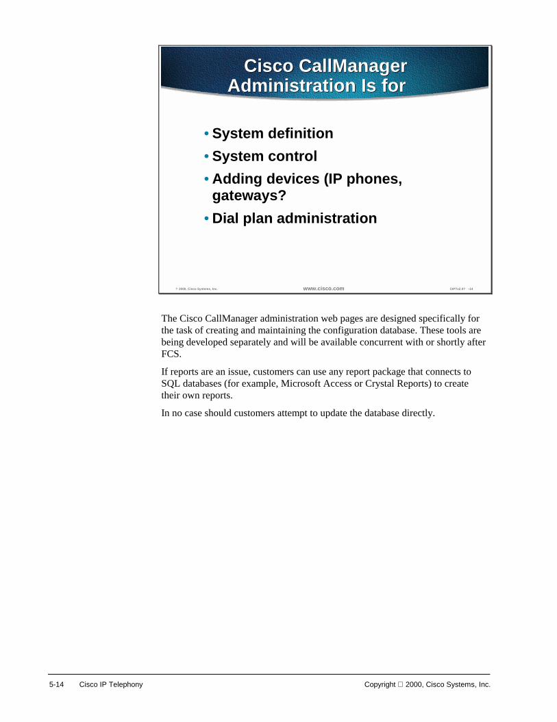
5-14 Cisco IP Telephony Copyright 2000, Cisco Systems, Inc.
? 2000, Cisco Systems, Inc. www.cisco.com CIPTv2.0? -14
Cisco CallManagerAdministration Is for�
Cisco CallManagerAdministration Is for�
• System definition• System control• Adding devices (IP phones,
gateways?• Dial plan administration
The Cisco CallManager administration web pages are designed specifically for the task of creating and maintaining the configuration database. These tools are being developed separately and will be available concurrent with or shortly after FCS.
If reports are an issue, customers can use any report package that connects to SQL databases (for example, Microsoft Access or Crystal Reports) to create their own reports.
In no case should customers attempt to update the database directly.

Copyright 2000, Cisco Systems, Inc. Cisco CallManager 5-15
? 2000, Cisco Systems, Inc. www.cisco.com CIPTv2.0? -15
InstallationInstallation
• Administration web is installed by defaultwith Cisco CallManager 3.0 software.
• Installed files for the web are now locatedoutside wwwroot in C:\Cisco\Webs\Admin.
• The files for the user web pages (forconfiguring speed dial and forward) areinstalled in C:\Cisco\Webs\User.
• Installation creates virtual directories onthe web server called CCMAdmin andCCMUser.
In version 2.x all the web page files for Cisco CallManager were installed under the default web site root folder (c:\inetpub\wwwroot). The User Web Pages were a subdirectory of the administration pages. This made setting security on the site easy for labs, but difficult for production systems.
In Cisco CallManager 3.0, the web files are installed outside the root web for better security. The user web pages have been broken out into a separate location to make security easier. Security is setup and maintained using NT’s directory and file permissions in combination with the permissions for the virtual directories on the web server. The virtual directories correspond to URLs of http://hostname/CCMAdmin and http://hostname/CCMUser, respectively (where hostname is the domain name or address of the web server).

5-16 Cisco IP Telephony Copyright 2000, Cisco Systems, Inc.
? 2000, Cisco Systems, Inc. www.cisco.com CIPTv2.0? -16
Menus and Navigation
Components of the Cisco CallManager 3.0 databaseare organized into a simple menu structure
Components of the Cisco CallManager 3.0 databaseare organized into a simple menu structure
The menus are used to organize and navigate the web pages for configuring the system. Click on a menu name to see contents (click on the name again to hide the menu). The menu content is organized as follows:
■ System—Items on this menu are used or available for the configuration of other items throughout the system. For example, the device pools used to group devices and associate devices with particular defaults.
■ Route Plan—Items used to configure routing and trunking for the system. This includes setting up partitions, partition (calling) search spaces, route groups and lists, and so forth. The External Route Plan Wizard is also available.
■ Services—Processes (applications and services) related to Cisco CallManager 3.0 run on the same or different machines (nodes) than a Cisco CallManager.
■ Features—Phone system features such as Call Park and Call Pickup Groups.
■ Devices—Hardware and software devices (phones and gateways) that carry or terminate calls. Also the keypad templates for phones.
■ Users—LDAP directory items for associating users and phones.
■ Applications—Plug-ins and other external applications that integrate with Cisco CallManager. For example, the Bulk Administration Tool, Voice Mail, CDR reporting and other applications that are installed separately from the main Cisco CallManager installation.
■ Help—The online help for Cisco CallManager and installed components.
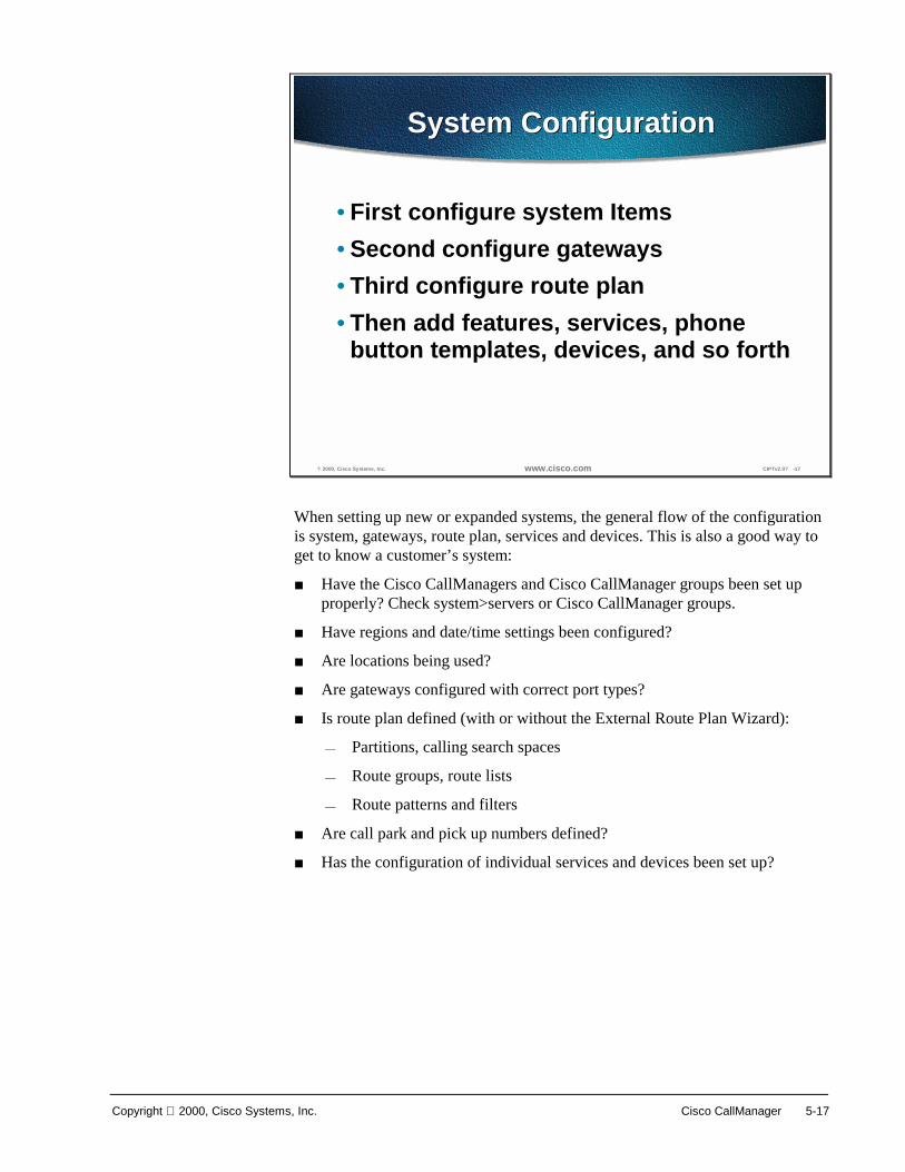
Copyright 2000, Cisco Systems, Inc. Cisco CallManager 5-17
? 2000, Cisco Systems, Inc. www.cisco.com CIPTv2.0? -17
System ConfigurationSystem Configuration
• First configure system Items• Second configure gateways• Third configure route plan• Then add features, services, phone
button templates, devices, and so forth
When setting up new or expanded systems, the general flow of the configuration is system, gateways, route plan, services and devices. This is also a good way to get to know a customer’s system:
■ Have the Cisco CallManagers and Cisco CallManager groups been set up properly? Check system>servers or Cisco CallManager groups.
■ Have regions and date/time settings been configured?
■ Are locations being used?
■ Are gateways configured with correct port types?
■ Is route plan defined (with or without the External Route Plan Wizard):
— Partitions, calling search spaces
— Route groups, route lists
— Route patterns and filters
■ Are call park and pick up numbers defined?
■ Has the configuration of individual services and devices been set up?

5-18 Cisco IP Telephony Copyright 2000, Cisco Systems, Inc.
Locating Items to Configure
? 2000, Cisco Systems, Inc. www.cisco.com CIPTv2.0? -18
Locating Low- to MediumCount Items to ConfigureLocating Low- to MediumCount Items to Configure
Low- to Medium-Count itemsLow- to Medium-Count items
Low- to medium-count items such as Cisco CallManagers, device pools, and analog stations are listed on the left column of the configuration page.
Select an item from the left column to edit, update, or delete that item.
In Cisco CallManager Administration, select system from the tool bar and device pool from the drop down menu to get to the page shown above.

Copyright 2000, Cisco Systems, Inc. Cisco CallManager 5-19
? 2000, Cisco Systems, Inc. www.cisco.com CIPTv2.0? -19
Locating High-Count Items toConfigure
Locating High-Count Items toConfigure
High-count items are located using aseparate search page to list relevant items.
High-count items are located using aseparate search page to list relevant items.
Use the search options at the top of the page to create a query for devices. Phones and users are considered high-count items. Click on the links for a listed item to edit it, or click on one of its icons to perform actions (copy, delete, reset) from the list.
In Cisco CallManager Administration, select Device from the tool bar and Phones from the drop down menu. When you select “Find” without establishing any search criteria, all registered phones will be listed.

5-20 Cisco IP Telephony Copyright 2000, Cisco Systems, Inc.
Inserting and Updating Items
? 2000, Cisco Systems, Inc. www.cisco.com CIPTv2.0? -20
Inserting and Updating ItemsInserting and Updating Items
Validating and updating data is done using emote Scripting? to
access data on the server without leaving the current page.Validating and updating data is done using emote Scripting? to
access data on the server without leaving the current page.
One of the changes in 3.0 is the consolidation of information on a single page. Settings that the user can’t or shouldn’t modify are removed so that more related items are on the same page. The change is most noticeable on the device pages.
Another change is the use of remote scripting to reduce the amount of processing done by the server. A key benefit of this technology is that the database can be accessed without leaving the current page. The ability to quickly validate against large databases (for example, detect a duplicate device name or directory number in a system with 1000s of stations) and give the user feedback.
Most updates are done using remote scripting so the server only has to process the data. The older form submission method sometimes required more processing for the HTML than the data. Another advantage is that we can now give the user error messages without requiring them to navigate between pages and re-enter data.

Copyright 2000, Cisco Systems, Inc. Cisco CallManager 5-21
? 2000, Cisco Systems, Inc. www.cisco.com CIPTv2.0? -21
Remote Scripting (Diagram)Remote Scripting (Diagram)
Initial Page Request
CiscoCallManager
Database
WebServer
ClientBrowser
DBL
Refresh Options on Input
Data Validation
Insert, Modify, Delete
Reload Page
Standard HTTPRequest/Response
Remote Scripting
Remote scripting is Microsoft’s name for accessing objects and data on a web server without reloading an entire page.
There are standards under development to make this functionality available in a non-proprietary way and across platforms.
Remote scripting lets us efficiently provide administrators with immediate feedback. For example, when an administrator enters the directory number for a line being added to a phone, we can tell them immediately if that directory number is already assigned to another device. This brings us closer to the performance expected in an application.
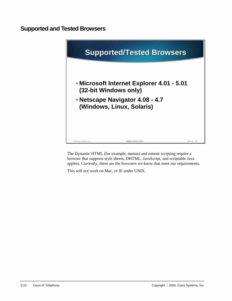
5-22 Cisco IP Telephony Copyright 2000, Cisco Systems, Inc.
Supported and Tested Browsers
? 2000, Cisco Systems, Inc. www.cisco.com CIPTv2.0? -22
Supported/Tested BrowsersSupported/Tested Browsers
• Microsoft Internet Explorer 4.01 - 5.01(32-bit Windows only)
• Netscape Navigator 4.08 - 4.7(Windows, Linux, Solaris)
The Dynamic HTML (for example, menus) and remote scripting require a browser that supports style sheets, DHTML, JavaScript, and scriptable Java applets. Currently, these are the browsers we know that meet our requirements.
This will not work on Mac, or IE under UNIX.

Copyright 2000, Cisco Systems, Inc. Cisco CallManager 5-23
External Route Plan Wizard
? 2000, Cisco Systems, Inc. www.cisco.com CIPTv2.0? -23
External Route Plan Wizard
Administrators cananswer a few
simple questions tocreate a full-
featured Route Plan
Administrators cananswer a few
simple questions tocreate a full-
featured Route Plan
The Wizard provides a way to set up specific information about the way calls are handled in the system without having to know all the details for Cisco CallManager 3.0’s implementation of call routing.
A route plan determines how a call placed from a station in the Cisco CallManager system is routed to its destination. The External Route Plan Wizard has been designed to allow a user with a limited amount of experience setting up route plans to quickly create and assign the items necessary for:
■ Controlling access to long distance calling
■ Provide emergency (911) access to all phones
■ Enabling toll bypass between multiple locations (use private network instead of PSTN)
■ Integrating the Cisco CallManager system with an existing PBX’s route plan
■ Additional information is shown on the Wizard’s first screen. Note in particular that the Wizard is for the North American Numbering Plan, and will not work for sites/customers in locations that require different numbering plans (for example, Europe, Asia, and so forth).
The Wizard creates all the necessary items, which can then be used to configure other devices (for example, phones). Items created by the wizard can be modified, and additional items can be added (for example, additional filters for blocking 900 services or directory assistance). However, once the items created by the Wizard are applied to devices or modified, you can no longer delete the dial plan without first undoing other changes.
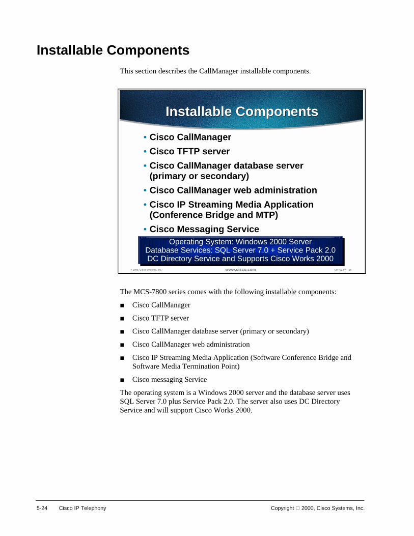
5-24 Cisco IP Telephony Copyright 2000, Cisco Systems, Inc.
Installable Components This section describes the CallManager installable components.
? 2000, Cisco Systems, Inc. www.cisco.com CIPTv2.0? -25
Installable ComponentsInstallable Components
• Cisco CallManager• Cisco TFTP server• Cisco CallManager database server
(primary or secondary)• Cisco CallManager web administration• Cisco IP Streaming Media Application
(Conference Bridge and MTP)• Cisco Messaging Service
Operating System: Windows 2000 ServerDatabase Services: SQL Server 7.0 + Service Pack 2.0DC Directory Service and Supports Cisco Works 2000
Operating System: Windows 2000 ServerDatabase Services: SQL Server 7.0 + Service Pack 2.0DC Directory Service and Supports Cisco Works 2000
The MCS-7800 series comes with the following installable components:
■ Cisco CallManager
■ Cisco TFTP server
■ Cisco CallManager database server (primary or secondary)
■ Cisco CallManager web administration
■ Cisco IP Streaming Media Application (Software Conference Bridge and Software Media Termination Point)
■ Cisco messaging Service
The operating system is a Windows 2000 server and the database server uses SQL Server 7.0 plus Service Pack 2.0. The server also uses DC Directory Service and will support Cisco Works 2000.

Copyright 2000, Cisco Systems, Inc. Cisco CallManager 5-25
Software License Keys
? 2000, Cisco Systems, Inc. www.cisco.com CIPTv2.0? -26
Software License KeysSoftware License Keys
• Files on CDs areencrypted
• Unique license key perapplication
• Installation flowcontrolled by license key
Installation FlowInstallation Flow
You cannot install partial software pieces. Forexample; Win2k, or SQL Server only.You cannot install Cisco CallManager 3.0 onrogue Win2K install.
You cannot install partial software pieces. Forexample; Win2k, or SQL Server only.You cannot install Cisco CallManager 3.0 onrogue Win2K install.
All files of the installable components CD’s are encrypted and each application has its own unique license key. Each application’s license key controls the flow of installation.
You are unable to install partial software. For example, you are unable to install only a Windows 2000 server or SQL server on a machine. The keys and encrypted files prevent partial installs of the software.
Because of the unique keys per application and the CD encryption, you are unable to install Cisco CallManager on a rogue Windows 2000 server installation.
Note In order to maintain the integrity of the system performance, no other third party applications can be installed or run on the system.

5-26 Cisco IP Telephony Copyright 2000, Cisco Systems, Inc.
Application Considerations
? 2000, Cisco Systems, Inc. www.cisco.com CIPTv2.0? -27
Application ConsiderationsApplication Considerations
• Browsers:–Must support both JavaScript and Active
Server Pages (ASP)–Microsoft Internet Explorer 4.01 or later–Netscape 4.5 or later
• Dynamic Host Configuration Protocol (DHCP)• Domain Name System (DNS) used for name
resolution when DHCP options provide names
Several utilities are necessary for using Cisco CallManager. The Browser used must support both JavaScript and Active Server Pages (ASP). The browser must also be Microsoft Internet Explorer 4.01 or later or Netscape 4.5 or later.
The Dynamic Host Configuration Protocol (DHCP) is used to provide an IP address lease and the location of the TFTP server. If DHCP is not available, a BOOTP server may be used.
The Domain Name System (DNS) is required for name resolutions. When a centralized DNS is used with a distributed clustered environment, a single point of failure to resolve Domain names could be an issue. If a link to DNS is down, phones may not be able to resolve CallManager Domain names and without registration to a CallManager, phones are out of service.
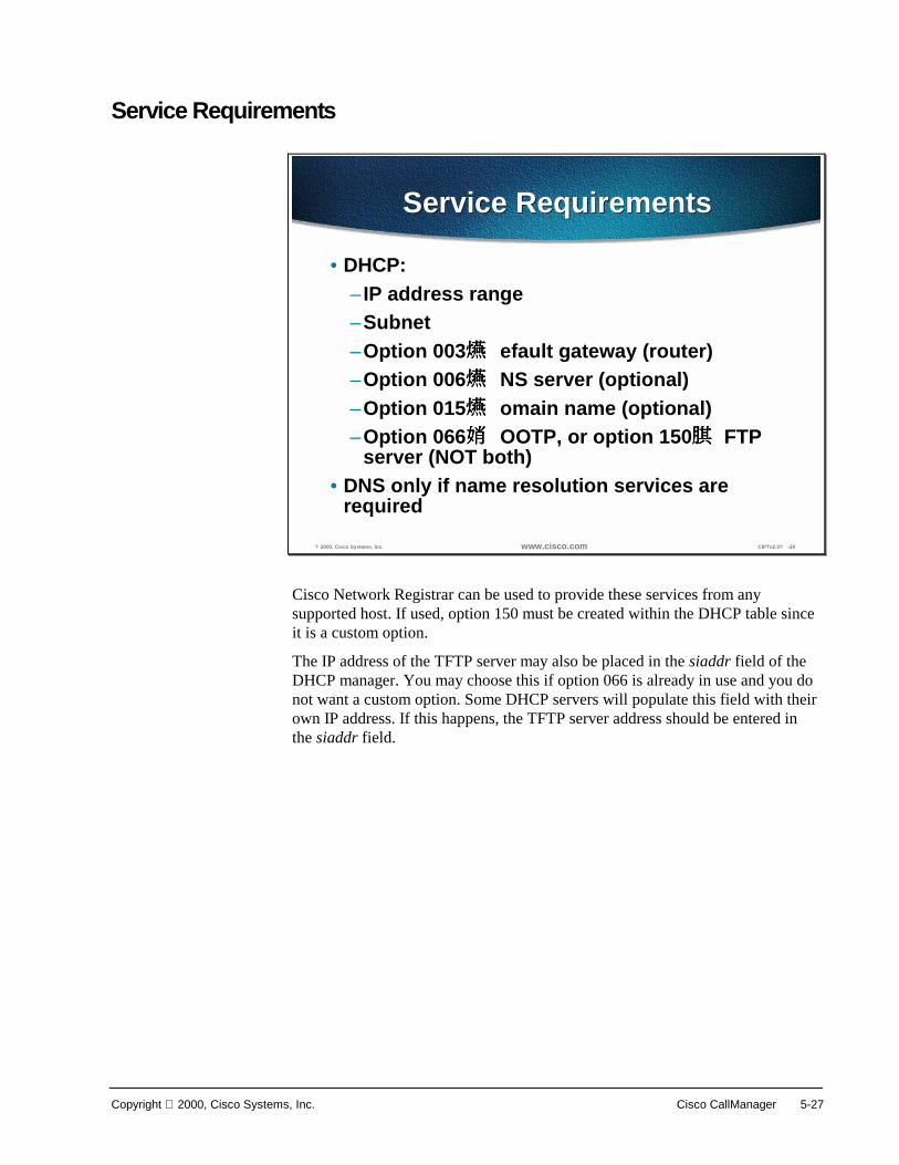
Copyright 2000, Cisco Systems, Inc. Cisco CallManager 5-27
Service Requirements
? 2000, Cisco Systems, Inc. www.cisco.com CIPTv2.0? -28
Service RequirementsService Requirements
• DHCP:– IP address range–Subnet–Option 003 efault gateway (router)
–Option 006 NS server (optional)
–Option 015 omain name (optional)
–Option 066 OOTP, or option 150 FTP server (NOT both)
• DNS only if name resolution services arerequired
Cisco Network Registrar can be used to provide these services from any supported host. If used, option 150 must be created within the DHCP table since it is a custom option.
The IP address of the TFTP server may also be placed in the siaddr field of the DHCP manager. You may choose this if option 066 is already in use and you do not want a custom option. Some DHCP servers will populate this field with their own IP address. If this happens, the TFTP server address should be entered in the siaddr field.
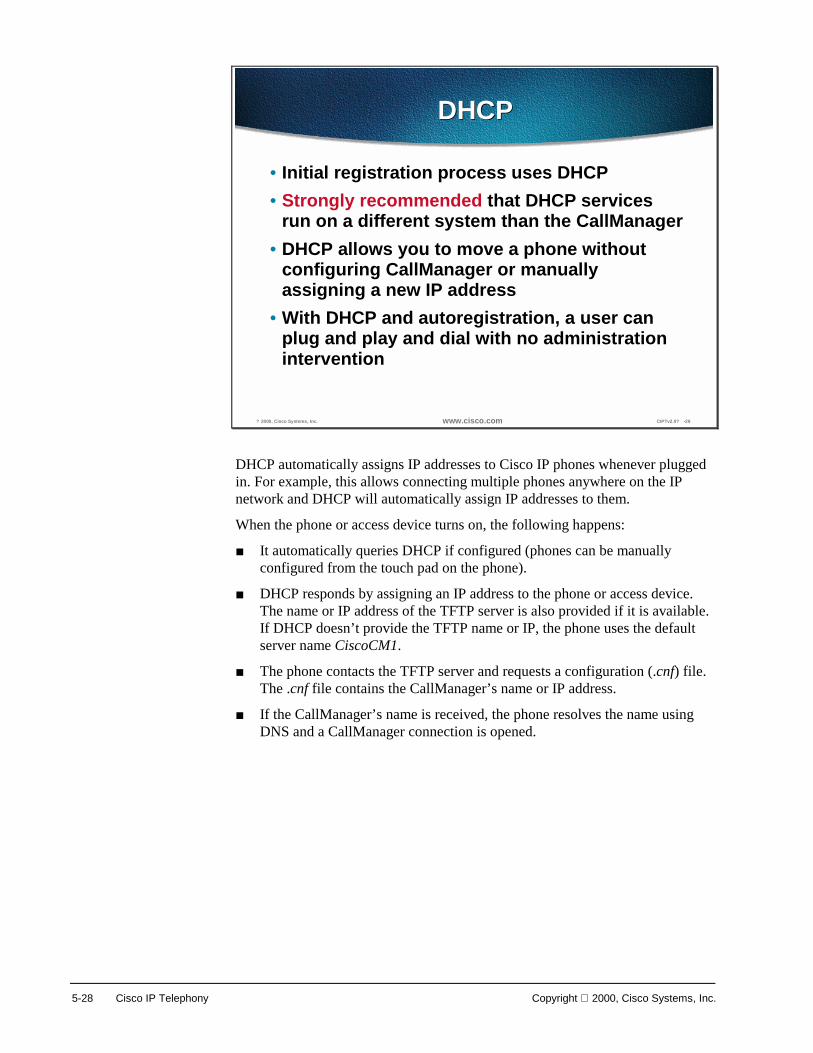
5-28 Cisco IP Telephony Copyright 2000, Cisco Systems, Inc.
? 2000, Cisco Systems, Inc. www.cisco.com CIPTv2.0? -29
DHCPDHCP
• Initial registration process uses DHCP• Strongly recommended that DHCP services
run on a different system than the CallManager• DHCP allows you to move a phone without
configuring CallManager or manuallyassigning a new IP address
• With DHCP and autoregistration, a user canplug and play and dial with no administrationintervention
DHCP automatically assigns IP addresses to Cisco IP phones whenever plugged in. For example, this allows connecting multiple phones anywhere on the IP network and DHCP will automatically assign IP addresses to them.
When the phone or access device turns on, the following happens:
■ It automatically queries DHCP if configured (phones can be manually configured from the touch pad on the phone).
■ DHCP responds by assigning an IP address to the phone or access device. The name or IP address of the TFTP server is also provided if it is available. If DHCP doesn’t provide the TFTP name or IP, the phone uses the default server name CiscoCM1.
■ The phone contacts the TFTP server and requests a configuration (.cnf) file. The .cnf file contains the CallManager’s name or IP address.
■ If the CallManager’s name is received, the phone resolves the name using DNS and a CallManager connection is opened.
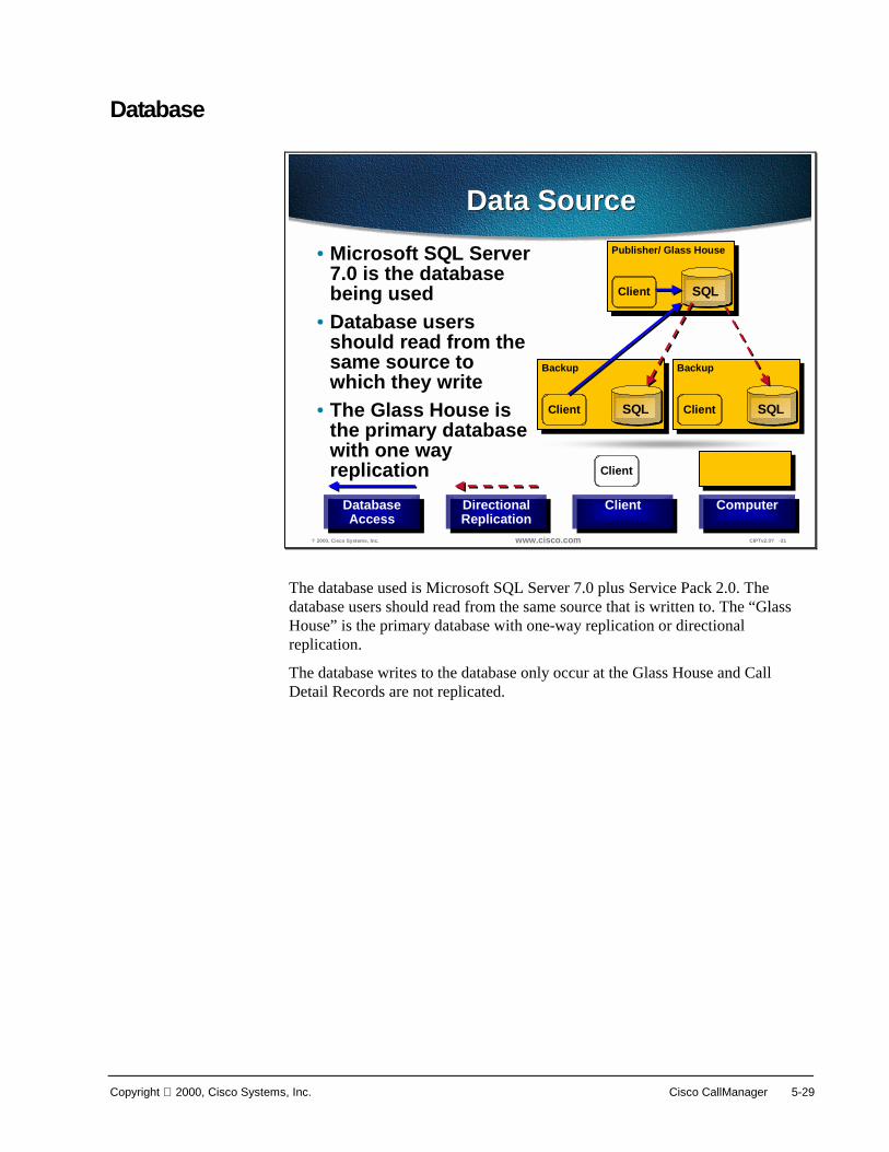
Copyright 2000, Cisco Systems, Inc. Cisco CallManager 5-29
Database
? 2000, Cisco Systems, Inc. www.cisco.com CIPTv2.0? -31
Data SourceData Source• Microsoft SQL Server
7.0 is the databasebeing used
• Database usersshould read from thesame source towhich they write
• The Glass House isthe primary databasewith one wayreplication
DirectionalReplicationDirectionalReplication
DatabaseAccess
DatabaseAccess
ComputerComputerClientClient
Client
Publisher/ Glass House
SQLClient
Backup
SQLClient
Backup
SQLClient
The database used is Microsoft SQL Server 7.0 plus Service Pack 2.0. The database users should read from the same source that is written to. The “Glass House” is the primary database with one-way replication or directional replication.
The database writes to the database only occur at the Glass House and Call Detail Records are not replicated.
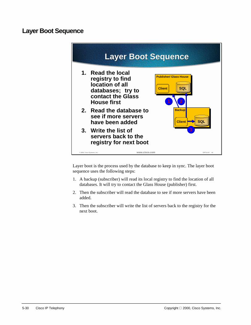
5-30 Cisco IP Telephony Copyright 2000, Cisco Systems, Inc.
Layer Boot Sequence
? 2000, Cisco Systems, Inc. www.cisco.com CIPTv2.0? -32
Layer Boot SequenceLayer Boot Sequence
1. Read the localregistry to findlocation of alldatabases; try tocontact the GlassHouse first
2. Read the database tosee if more servershave been added
3. Write the list ofservers back to theregistry for next boot
Publisher/ Glass House
SQLClient
Backup
SQLClient
1 2
3
Layer boot is the process used by the database to keep in sync. The layer boot sequence uses the following steps:
1. A backup (subscriber) will read its local registry to find the location of all databases. It will try to contact the Glass House (publisher) first.
2. Then the subscriber will read the database to see if more servers have been added.
3. Then the subscriber will write the list of servers back to the registry for the next boot.

Copyright 2000, Cisco Systems, Inc. Cisco CallManager 5-31
© 2000, Cisco Systems, Inc. www.cisco.com CIPTv2.0—5-33
Hiding the Data Source and Failover
1. The database layer first tries to use the Glass House (read and write)
2. If Glass House is not available, try a replicated database; if one exists on the local machine, try it before any other
Publisher/ Glass House
SQLClient
Backup
SQLClient
1
2
During a failover, the database layer prevents writes to the database except for Call Detail Records.
During a failover, the database layer prevents writes to the database except for Call Detail Records.
XX
The data source on the local machine is hidden so that it will try to use the Glass House (Glass House = publisher) (read and write) database. If the Glass House is not available the local machine will try a replicated database on its own machine. If it does not have a database on the local machine, the local machine will try other subscribers for a database.

5-32 Cisco IP Telephony Copyright 2000, Cisco Systems, Inc.
Installation
? 2000, Cisco Systems, Inc. www.cisco.com CIPTv2.0? -35
Cisco CallManager OperatingSystem Installation CD
Cisco CallManager OperatingSystem Installation CD
• Microsoft Windows 2000 Server• Microsoft SQL Server 7.0 Standard Edition,
Service Pack 2• DC Directory 2.4• Cisco CallManager 3.0
Software Applications Installed AutomaticallySoftware Applications Installed Automatically
The Cisco CallManager Operating System Installation CD must be inserted into the Cisco Media Convergence Server before powering up the server. After the system boots, the MCS QuickBuilder installation utility, located on the CD, loads automatically and guides you through the installation process. MCS QuickBuilder performs several pre-installation tasks, including preparing your server’s hard drive and loading server configuration information, and then automatically installs the following software applications:
■ Microsoft Windows 2000 Server
■ Microsoft SQL Server 7.0 Standard Edition, Service Pack 2
■ DC Directory 2.4—is an LDAP Compliant Directory
■ Cisco CallManager 3.0
Note During installation, the server reboots several times. Do not power off the server any time during this process, unless instructed. Any unexpected power interruption during the installation process could prevent proper completion of the configuration and might prevent the operating system from restarting.
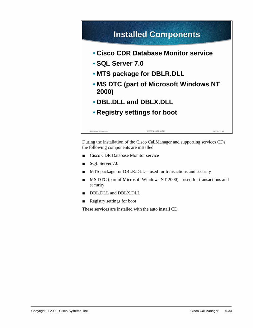
Copyright 2000, Cisco Systems, Inc. Cisco CallManager 5-33
? 2000, Cisco Systems, Inc. www.cisco.com CIPTv2.0? -36
Installed ComponentsInstalled Components
• Cisco CDR Database Monitor service• SQL Server 7.0• MTS package for DBLR.DLL• MS DTC (part of Microsoft Windows NT
2000)• DBL.DLL and DBLX.DLL• Registry settings for boot
During the installation of the Cisco CallManager and supporting services CDs, the following components are installed:
■ Cisco CDR Database Monitor service
■ SQL Server 7.0
■ MTS package for DBLR.DLL—used for transactions and security
■ MS DTC (part of Microsoft Windows NT 2000)—used for transactions and security
■ DBL.DLL and DBLX.DLL
■ Registry settings for boot
These services are installed with the auto install CD.

5-34 Cisco IP Telephony Copyright 2000, Cisco Systems, Inc.
? 2000, Cisco Systems, Inc. www.cisco.com CIPTv2.0? -37
MigrationMigration
2.4 Migration• Requires path to MDB file• Same machine upgrade requires more
memory
3.0 Migration• Changes database name• Three previous versions kept on server
Migration from Cisco CallManager 2.4 to 3.0 it requires a path to the MDB file. The Migration from 2.4 to 3.0 does require a memory upgrade if using a MCS-7820 to 512 MB RAM or MCS-7830 requires 512 MB to 1 GB RAM.
If migrating from a Cisco CallManager 3.0 to Cisco CallManager 3.0 the database name changes.

Copyright 2000, Cisco Systems, Inc. Cisco CallManager 5-35
Starting and Stopping Cisco CallManager
? 2000, Cisco Systems, Inc. www.cisco.com CIPTv2.0? -39
Three MethodsThree Methods
• Control Center in Cisco CallManagerAdministration
• Windows Control Panel for Services• Reset button in Cisco CallManager
Administration
• Control Center in Cisco CallManagerAdministration
• Windows Control Panel for Services• Reset button in Cisco CallManager
Administration
Stopping Cisco CallManager stops call processing for all devicescontrolled by that Cisco CallManager. If you have not configured abackup Cisco CallManager for those devices, any calls in progresson those devices are dropped.
Stopping Cisco CallManager stops call processing for all devicescontrolled by that Cisco CallManager. If you have not configured abackup Cisco CallManager for those devices, any calls in progresson those devices are dropped.
Stopping Cisco CallManager stops call processing for all devices controlled by that Cisco CallManager. If a backup Cisco CallManager is not configured for those devices, any call in progress on those devices is dropped. There are the following three methods for stopping a Cisco CallManager:
■ Control Center in the Cisco CallManager Administration
■ Windows control panel for services
■ Reset button in Cisco CallManager Administration
Note If a screen on the CallManager Administration page has a reset button, you only need to reset the device. If the screen does not have a reset button, you must restart the Cisco CallManager.

5-36 Cisco IP Telephony Copyright 2000, Cisco Systems, Inc.
? 2000, Cisco Systems, Inc. www.cisco.com CIPTv2.0? -40
Parameter Settings thatRequire a Restart
Parameter Settings thatRequire a Restart
• IP Address of the Cisco CallManagerserver
• Partition for auto-registration• External phone number mask for auto-
registration• TCP port settings for the Cisco
CallManager server
• IP Address of the Cisco CallManagerserver
• Partition for auto-registration• External phone number mask for auto-
registration• TCP port settings for the Cisco
CallManager server
Tip: Make as many configuration changes aspossible at one time, and restart Cisco CallManageronly once after completing the changes
Tip: Make as many configuration changes aspossible at one time, and restart Cisco CallManageronly once after completing the changes
It is better to make as many configuration changes as possible at one time, and restart Cisco CallManager only once after completing the changes. The following system parameter settings require a restart:
1. IP Address of the Cisco CallManager server
2. Partition for auto-registration
3. External phone number mask for auto-registration
4. TCP port settings for the Cisco CallManager server

Copyright 2000, Cisco Systems, Inc. Cisco CallManager 5-37
Troubleshooting
? 2000, Cisco Systems, Inc. www.cisco.com CIPTv2.0? -41
Troubleshooting(Version Information)
Details button on Aboutpage shows databaseconnection and DBLversion information
Details button on Aboutpage shows databaseconnection and DBLversion information
When supporting a customer, the first thing to check is the information listed in the Details. This includes system and Cisco CallManager administration versions, database connection information, and DBL versions. Errors in displaying this information can be a sign of errors in the general system setup or configuration.
If the database connection information is missing, refresh the page and check again. If the information is still missing, there’s a good chance that a problem exists in the connection to or configuration of the Cisco CallManager(s) and SQL server(s).
If the DBL information is missing, there is a problem with the DBL. Try re-registering the DBL DLLs and refreshing MTS components.
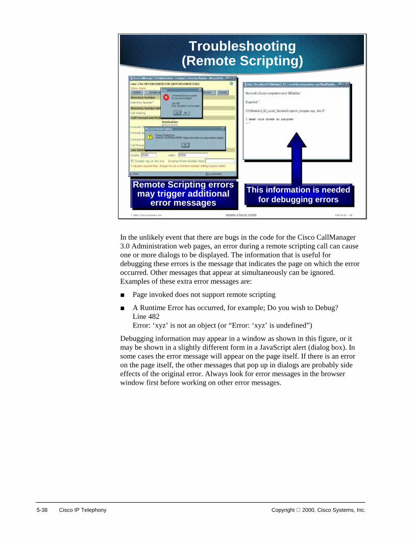
5-38 Cisco IP Telephony Copyright 2000, Cisco Systems, Inc.
? 2000, Cisco Systems, Inc. www.cisco.com CIPTv2.0? -42
Troubleshooting(Remote Scripting)
Remote Scripting errorsmay trigger additional
error messages
Remote Scripting errorsmay trigger additional
error messagesThis information is needed
for debugging errorsThis information is needed
for debugging errors
In the unlikely event that there are bugs in the code for the Cisco CallManager 3.0 Administration web pages, an error during a remote scripting call can cause one or more dialogs to be displayed. The information that is useful for debugging these errors is the message that indicates the page on which the error occurred. Other messages that appear at simultaneously can be ignored. Examples of these extra error messages are:
■ Page invoked does not support remote scripting
■ A Runtime Error has occurred, for example; Do you wish to Debug? Line 482 Error: ‘xyz’ is not an object (or “Error: ‘xyz’ is undefined”)
Debugging information may appear in a window as shown in this figure, or it may be shown in a slightly different form in a JavaScript alert (dialog box). In some cases the error message will appear on the page itself. If there is an error on the page itself, the other messages that pop up in dialogs are probably side effects of the original error. Always look for error messages in the browser window first before working on other error messages.

Copyright 2000, Cisco Systems, Inc. Cisco CallManager 5-39
Laboratory Exercises

5-40 Cisco IP Telephony Copyright 2000, Cisco Systems, Inc.
Summary This section summarizes the concepts you learned in this chapter.
? 2000, Cisco Systems, Inc. www.cisco.com CIPTv2.0? -43
SummarySummary
• The MCS-7800 platforms are the hardwareplatforms for the Cisco CallManager.
• The primary function of the Cisco CallManageris call processing.
• Cisco CallManager Administration is used toestablish parameters and configuring devices.
• Inter-cluster communication is provided viaH.323.
The MCS-7830 and the MCS-7835 are the hardware platforms for the Cisco CallManager. Each server is a high availability server that comes with the following software:
■ Cisco CallManager and all of its components and plug-ins
■ Windows 2000
■ SQL 7.0
■ SQL 7.0 Service Pack 2
■ Compaq Remote Insight Manager
■ Windows 2000 Resource Kit (components)
■ Executive Software Diskeeper Server (defrag software)
Cisco CallManager Administration is used for setting parameters, adding and configuring devices, and updating user information.
Inter-cluster communication is provided via H.323 that permits a subset of the features to be extended between clusters.
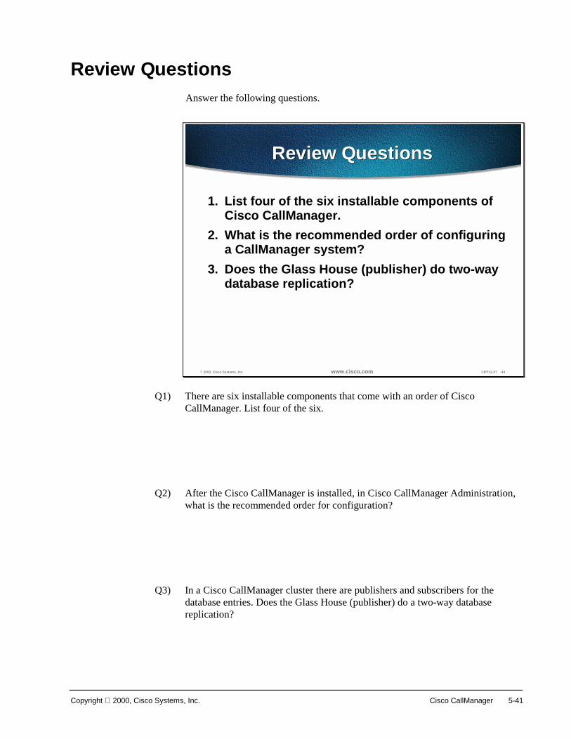
Copyright 2000, Cisco Systems, Inc. Cisco CallManager 5-41
Review Questions Answer the following questions.
? 2000, Cisco Systems, Inc. www.cisco.com CIPTv2.0? -44
Review QuestionsReview Questions
1. List four of the six installable components ofCisco CallManager.
2. What is the recommended order of configuringa CallManager system?
3. Does the Glass House (publisher) do two-waydatabase replication?
Q1) There are six installable components that come with an order of Cisco CallManager. List four of the six.
Q2) After the Cisco CallManager is installed, in Cisco CallManager Administration, what is the recommended order for configuration?
Q3) In a Cisco CallManager cluster there are publishers and subscribers for the database entries. Does the Glass House (publisher) do a two-way database replication?

6
Overview Cisco CallManager Services are the services that are optionally enabled on every Cisco CallManager in a cluster. These services provide configuration files, connecting to a third party voice mail system, and conferencing and media terminating functions.
In this chapter, the following topics will be discussed:
■ Objectives
■ Cisco TFTP
■ Cisco Messaging Interface
■ Cisco IP Voice Media Streaming Application
■ Summary
■ Review Questions
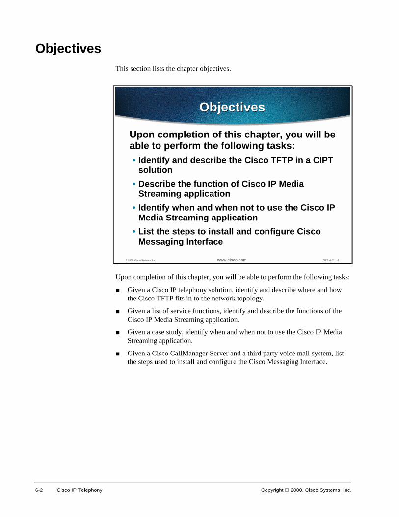
6-2 Cisco IP Telephony Copyright 2000, Cisco Systems, Inc.
Objectives This section lists the chapter objectives.
? 2000, Cisco Systems, Inc. www.cisco.com CIPT v2.0? -3
ObjectivesObjectives
Upon completion of this chapter, you will beable to perform the following tasks:• Identify and describe the Cisco TFTP in a CIPT
solution• Describe the function of Cisco IP Media
Streaming application• Identify when and when not to use the Cisco IP
Media Streaming application• List the steps to install and configure Cisco
Messaging Interface
Upon completion of this chapter, you will be able to perform the following tasks:
■ Given a Cisco IP telephony solution, identify and describe where and how the Cisco TFTP fits in to the network topology.
■ Given a list of service functions, identify and describe the functions of the Cisco IP Media Streaming application.
■ Given a case study, identify when and when not to use the Cisco IP Media Streaming application.
■ Given a Cisco CallManager Server and a third party voice mail system, list the steps used to install and configure the Cisco Messaging Interface.

Copyright 2000, Cisco Systems, Inc. Cisco CallManager Services 6-3
Cisco TFTP This section describes the Cisco Trivial File Transfer Protocol (TFTP).
? 2000, Cisco Systems, Inc. www.cisco.com CIPT v2.0? -5
What Is Cisco Trivial FileTransfer Protocol (TFTP)?What Is Cisco Trivial File
Transfer Protocol (TFTP)?
• Cisco TFTP is a Windows NT 2000service
• Cisco TFTP builds configuration filesfrom information found in the database
• Cisco TFTP Serves configuration,executable, and ringer files consistentwith ITU RFC 1350
Cisco Trivial File Transfer Protocol (Cisco TFTP) is a Windows NT 2000 service. The Cisco TFTP service builds configuration files from information found in the database. Cisco TFTP serves configuration, executable, and ringer files consistent with ITU RFC 1350.
The configuration files are device specific with the name format SEP, SAA, SDA, CFB, or MTP + MAC, for example, SEP001002003004.cnf.
■ SEP—Selsius Ethernet Phone (Cisco 12 SP+, 30 VIP and 7960)
■ SAA—Selsius Analog Access (AT-2,4,8 and AS-2,4,8)
■ SDA—Selsius Digital Access (DT-24+, DE-30+)
■ CFB—Conference Bridge
■ MTP—Media Termination Point
Configuration files also contain a list of CallManagers in priority order. Network addresses are either the fully qualified domain name “cm1.cisco.com” or dotted IP address “172.116.21.12” plus a TCP Port (see Call Manager Group Configuration). The configuration files for a 7960 include URL’s for four buttons (Messages, Directories, Services, and Information).

6-4 Cisco IP Telephony Copyright 2000, Cisco Systems, Inc.
Configuration File Request
? 2000, Cisco Systems, Inc. www.cisco.com CIPT v2.0? -6
From Device Record toConfiguration File
From Device Record toConfiguration File
Device PoolDevice PoolCisco
CallManagerGroup
CiscoCallManager
Group
Cisco CallManager ListA ? CCM1B ? CCM2C ? CCM3
Cisco CallManager ListA ? CCM1B ? CCM2C ? CCM3
CCM1TCP connection port
SEP - 2000SAA - 2001SDA - 2002
CCM1TCP connection port
SEP - 2000SAA - 2001SDA - 2002
If the device is a 7960, button URLs can be specified in DeviceConfiguration. If a 7960’s URLs are blank, the enterprise values are used.
If the device is a 7960, button URLs can be specified in DeviceConfiguration. If a 7960’s URLs are blank, the enterprise values are used.
A device has a communication request record that needs to download a configuration file. The following is the process used by a device to get to the configuration file:
■ A device specifies a device pool. ■ A device pool specifies a CallManager group.
■ A CallManager group specifies a list of CallManagers.
■ CallManagers contain the TCP connection port for the three device types (telephone, analog gateway, and digital gateway).
If the device is a 7960, button URLs can be specified in device configuration. If a 7960’s URLs are blank, the enterprise values are used.
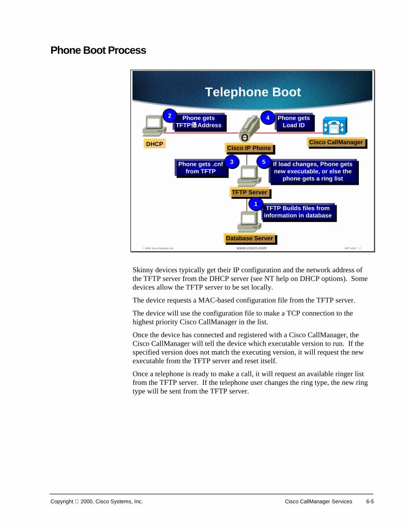
Copyright 2000, Cisco Systems, Inc. Cisco CallManager Services 6-5
Phone Boot Process
? 2000, Cisco Systems, Inc. www.cisco.com CIPT v2.0? -7
If load changes, Phone getsnew executable, or else the
phone gets a ring list
If load changes, Phone getsnew executable, or else the
phone gets a ring list
Phone getsLoad ID
Phone getsLoad ID
Phone gets .cnffrom TFTP
Phone gets .cnffrom TFTP
Phone getsTFTP Address
Phone getsTFTP Address
TFTP Builds files frominformation in databaseTFTP Builds files from
information in database
Telephone Boot
Cisco CallManagerCisco CallManager
Database ServerDatabase Server
DHCP
22 44
Cisco IP PhoneCisco IP Phone
TFTP ServerTFTP Server
33 55
11
Skinny devices typically get their IP configuration and the network address of the TFTP server from the DHCP server (see NT help on DHCP options). Some devices allow the TFTP server to be set locally.
The device requests a MAC-based configuration file from the TFTP server.
The device will use the configuration file to make a TCP connection to the highest priority Cisco CallManager in the list.
Once the device has connected and registered with a Cisco CallManager, the Cisco CallManager will tell the device which executable version to run. If the specified version does not match the executing version, it will request the new executable from the TFTP server and reset itself.
Once a telephone is ready to make a call, it will request an available ringer list from the TFTP server. If the telephone user changes the ring type, the new ring type will be sent from the TFTP server.

6-6 Cisco IP Telephony Copyright 2000, Cisco Systems, Inc.
Cisco TFTP Architecture
© 2000, Cisco Systems, Inc. www.cisco.com CIPT v2.0—6-8
Cisco TFTP Architecture
Database Layer –Monitor (Aupair)
Database Layer –Monitor (Aupair)
Database Layer - DLL
Database Layer - DLL
TFTP Change Notification
TFTP Change Notification
Performance Monitor Interface
Performance Monitor Interface
TFTP Service (Build and Serve Files)
TFTP Service (Build and Serve Files) SDISDI
Service Control Manager
Service Control ManagerWinsockWinsockCisco TFTP
Package ViewCisco TFTP
Package View
The Cisco TFTP external interfaces include the following:
■ NT’s Service Control Manager
— Cisco TFTP is an auto start NT 2000 service so it runs even before any one logs in.
— The NT Service Control Manager can start, stop, or get status (starting, running, stopping, or stopped).
■ NT’s Winsock
— NT’s Winsock provides Cisco TFTP with a C interface to the IP network.
— Winsock is used to receive TFTP requests.
— Winsock is used to send file segments and receive acknowledgments for those file segments.
■ Selsius Diagnostic Interface (SDI) trace
— This library provides Cisco TFTP with a C interface to trace and alarms.
— SDI Trace can be directed to local files, NT Event Log, and Cisco Works.
— Trace allows the developer to know that the code is functioning properly or to find the cause of an error.

Copyright 2000, Cisco Systems, Inc. Cisco CallManager Services 6-7
— Alarms are used to inform the administrator of an unexpected event (unable to access a file, unable to access the database, unable to access Winsock, or unable to allocate other operating system resources).
■ Performance monitor
— This DLL provides Cisco TFTP with a C interface to NT PerfMon.
— TotalTftpPreBuilt has changed to TotalTftpOverflow.
■ Database layer DLL
— This DLL provides Cisco TFTP with a C++ interface to the Cisco Call Manager enterprise database (for the cluster). The database could be local or remote. If the primary database fails, the Layer handles the details transparently.
— Process configuration information includes trace information, alternate path information, and whether to delete files in the primary directory.
— Building file configuration includes device and CallManager information.
■ Database layer monitor (Aupair)
— This NT service provides Cisco TFTP with change notification through two call backs. One call back for process configuration changes and one for any other change that the TFTP server is interested in.
— This service is located with the database server objects.
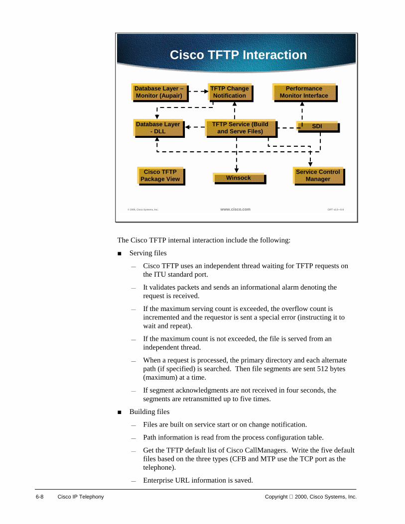
6-8 Cisco IP Telephony Copyright 2000, Cisco Systems, Inc.
© 2000, Cisco Systems, Inc. www.cisco.com CIPT v2.0—6-9
Cisco TFTP Interaction
Database Layer –Monitor (Aupair)
Database Layer –Monitor (Aupair)
Database Layer - DLL
Database Layer - DLL
TFTP Change Notification
TFTP Change Notification
Performance Monitor Interface
Performance Monitor Interface
TFTP Service (Build and Serve Files)
TFTP Service (Build and Serve Files) SDISDI
Service Control Manager
Service Control ManagerWinsockWinsockCisco TFTP
Package ViewCisco TFTP
Package View
The Cisco TFTP internal interaction include the following:
■ Serving files
— Cisco TFTP uses an independent thread waiting for TFTP requests on the ITU standard port.
— It validates packets and sends an informational alarm denoting the request is received.
— If the maximum serving count is exceeded, the overflow count is incremented and the requestor is sent a special error (instructing it to wait and repeat).
— If the maximum count is not exceeded, the file is served from an independent thread.
— When a request is processed, the primary directory and each alternate path (if specified) is searched. Then file segments are sent 512 bytes (maximum) at a time.
— If segment acknowledgments are not received in four seconds, the segments are retransmitted up to five times.
■ Building files
— Files are built on service start or on change notification.
— Path information is read from the process configuration table.
— Get the TFTP default list of Cisco CallManagers. Write the five default files based on the three types (CFB and MTP use the TCP port as the telephone).
— Enterprise URL information is saved.
Copyright 2000, Cisco Systems, Inc. Cisco CallManager Services 6-9
— For every device pool in the system, the list of CallManagers is retrieved and three prototype configuration files are built.
— For every device in the system, find the prototype configuration file, add the URL information as appropriate, and write out that file to the primary TFTP path.
■ Change notification
— For a process configuration change, all process configuration parameters are read and all the configuration files are rebuilt.
— For a Cisco CallManager change, the CallManager information is reread and if the information TFTP uses has changed, all configuration files are rebuilt.
— For group information change, all configuration files are rebuilt.
— For device change, only the affected device's configuration file is rebuilt unless the device is deleted, and then all configuration files are rebuilt.

6-10 Cisco IP Telephony Copyright 2000, Cisco Systems, Inc.
Change Notification
? 2000, Cisco Systems, Inc. www.cisco.com CIPT v2.0? -10
Inter-Cluster Communication
Cloud
DatabaseLayer DLLDatabaseLayer DLL
TFTPServiceTFTP
Service
Database LayerMonitor (Aupair)Database LayerMonitor (Aupair)
TFTP ChangeNotification DLLTFTP Change
Notification DLLTFTP
ServiceTFTP
Service
DatabaseLayer DLLDatabaseLayer DLL
DatabaseLayer DLLDatabaseLayer DLL TFTP Change
Notification DLLTFTP Change
Notification DLL
TFTPServiceTFTP
ServiceDatabaseLayer DLLDatabaseLayer DLL
TFTP ChangeNotification DLLTFTP Change
Notification DLL
TFTP ChangeNotification DLLTFTP Change
Notification DLL
The Cisco TFTP Change Notification DLL must exist on both the database server and where the Cisco TFTP server exists. The Change Notification DLL provides call-backs to the Database Monitor. Notifications are sent from the database server node to the TFTP server node using UDP. The TFTP server node receives the notification on a port specified in the database.
Device and Cisco CallManager changes are sent to all the TFTP servers immediately. Non-enterprise wide process configuration changes are debounced then sent to that particular server. Debouncing means if several changes of the same type occur in a specified amount of time the notification is delayed until changes stop occurring for that period.
Enterprise wide process configuration change, device pool changes, and call manager group changes are debounced in a similar way but notifications are sent to all TFTP servers.

Copyright 2000, Cisco Systems, Inc. Cisco CallManager Services 6-11
Installation and Configuration The standard install CD is used to install or reinstall the Cisco TFTP service. Make sure the TFTP check box is selected. This copies the files to the system (ctftp.exe, tftpperfmon.dll, and CtftpChangeNotify.dll). This installs the database servers and clients, such as, the service ctftp.exe, and PerfMon for TFTP (add registry entries and lodctr tftpperfmon.ini).
Most of the configuration is provided by the install defaults. It is recommended to use DNS names for your Cisco CallManager server names unless in a laboratory environment. Devices must be pointed at the TFTP server using option 150 in a DHCP server. The Trace options are configurable and the levels and output receptacles can be individually selected.
? 2000, Cisco Systems, Inc. www.cisco.com CIPT v2.0? -11
Multi-Cluster ConfigurationMulti-Cluster Configuration
DataData
DataData
DHCPDatabase Server
Database Server
Cluster 2Cluster 2
Cluster 1Cluster 1
Router/Gateway
AlternatePaths
AlternatePaths
TFTP Server/ CiscoCallManager
Option150
Option150
IP Network
TFTP Server/Cisco
CallManager
CiscoCallManager
CiscoCallManager
Cisco IPPhones
Router/Gateway
Cisco IPPhones
CiscoCallManager
CiscoCallManager
Every Cisco CallManager could have its own Cisco CallManager group and that Cisco CallManager will be the primary Cisco CallManager. Then assign devices to the appropriate Cisco CallManager group using device pools based on network topology.
Specify alternate paths if multiple clusters are trying to share configuration files. Disable file deletion if multiple cluster’s TFTP servers are sharing a single network drive. A single Cisco TFTP server in a cluster builds all the device configuration files, and a DHCP server can only point to one TFTP server for a scope. Within seven minutes, 10,000 telephones should transfer. Server installation and device pool configuration will be covered in detail later in this course.
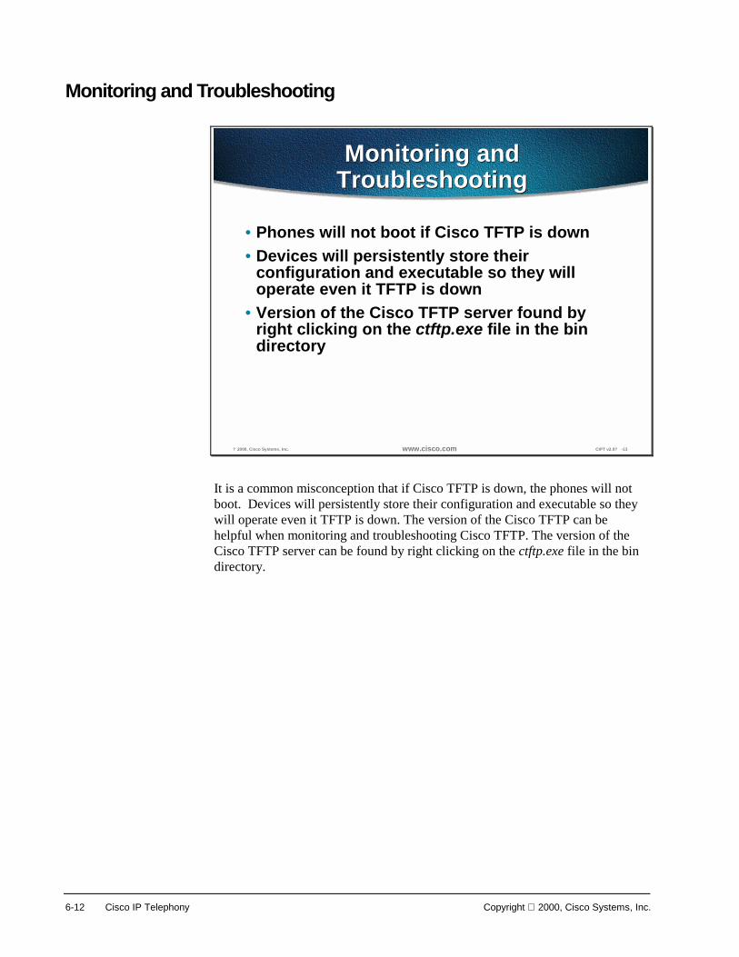
6-12 Cisco IP Telephony Copyright 2000, Cisco Systems, Inc.
Monitoring and Troubleshooting
? 2000, Cisco Systems, Inc. www.cisco.com CIPT v2.0? -13
Monitoring andTroubleshootingMonitoring and
Troubleshooting
• Phones will not boot if Cisco TFTP is down• Devices will persistently store their
configuration and executable so they willoperate even it TFTP is down
• Version of the Cisco TFTP server found byright clicking on the ctftp.exe file in the bindirectory
It is a common misconception that if Cisco TFTP is down, the phones will not boot. Devices will persistently store their configuration and executable so they will operate even it TFTP is down. The version of the Cisco TFTP can be helpful when monitoring and troubleshooting Cisco TFTP. The version of the Cisco TFTP server can be found by right clicking on the ctftp.exe file in the bin directory.

Copyright 2000, Cisco Systems, Inc. Cisco CallManager Services 6-13
© 2000, Cisco Systems, Inc. www.cisco.com CIPT v2.0—6-13
What Are Your Tools?What Are Your Tools?
• PerfMon• EventLog• CiscoWorks 2000• Local log files• Trace File
The tools for monitoring and troubleshooting Cisco TFTP are listed below in order of the priority line of defense:
■ Performance Monitoring (PerfMon)
— First line of defense and to open go to Start>Programs>Administrative Tools>Performance.
— If all counters are zero, the service is stopped.
■ EventLog
— Second line of defense and to open go to Start>Programs>Administrative Tools>Event Viewer>Application Log.
— Even if a service (including TFTP) cannot read the database (where it gets trace configuration), it will add errors to the event log. This is the only place this kind of error will appear.
■ CiscoWorks
— Great for getting an enterprise wide view.
— Receives events similar to event log with some differences.
■ Local log files
— Provide the greatest level of detail.
— Often times the files will only be understood by development engineers.
■ Trace File is enabled through Cisco CallManager Administration and user masks are turned on and the trace is written to a file at the path of; My Computer>Program Files>Cisco>Trace>CCM.

6-14 Cisco IP Telephony Copyright 2000, Cisco Systems, Inc.
© 1999, Cisco Systems, Inc. www.cisco.com CIPT—Chapter8-14
PerfMon KeysPerfMon Keys
1. HeartBeat2. TotalTftpRequests3. TotalTftpRequestsLocal4. Non-zero TotalTftpRequestsNotFound5. Non-zero TotalTftpRequestsAborted6. TotalTftpRequestsOverflow7. TotalTftpRequestsLocal8. TotalSegmentsSent and
TotalSegmentsAcknowledgeds
PerfMon is the first line of defense for monitoring and troubleshooting the PerfMon Keys are defined below:
1. HeartBeat should increase once a second.
2. TotalTftpRequests increment twice per 7960 boot (.cnf and ring list) and if the phone is requesting a custom ring the increment will be three per 7960 boot.
3. TotalTftpRequestsLocal increment twice per 7960 boot (.cnf and ring list).
4. Non-zero TotalTftpRequestsNotFound represents a problem (if not auto registering).
5. Non-zero TotalTftpRequestsAborted represents a problem.
6. TotalTftpRequestsOverflow implies the maximum simultaneous requests was exceeded. That is not necessarily a problem.
7. If only TotalTftpRequestsOverflow is going up and TotalTftpRequestsLocal is not going up for more than a minute, there is a problem.
8. Lots of TotalSegmentsSent without TotalSegmentsAcknowledgeds may imply the device has not got back to us.

Copyright 2000, Cisco Systems, Inc. Cisco CallManager Services 6-15
? 2000, Cisco Systems, Inc. www.cisco.com CIPT v2.0? -15
EventLogEventLog
• Clutter can make it more difficult to use• Source is Cisco TFTP• Configure the event level for otice�
or higher• Cisco TFTP may put entries in the
EventLog on boot until the database isup and running
The EventLog is the second line of defense for monitoring and troubleshooting Cisco TFTP. The source of the EventLog is Cisco TFTP. Because of clutter in the output from EventLog, it can be more difficult to use. If this is making testing difficult, configure the event level for “Notice” or higher. Cisco TFTP may put entries in the EventLog on boot until the database is up and running.

6-16 Cisco IP Telephony Copyright 2000, Cisco Systems, Inc.
? 2000, Cisco Systems, Inc. www.cisco.com CIPT v2.0? -16
Cisco Works 2000Cisco Works 2000
• Great for getting an enterprise wide view• Receives events similar to EventLog with
three differences– If Cisco TFTP cannot talk to the database, it
cannot send trace to Cisco Works– If your are having trouble with the network,
the log messages must travel across thenetwork
– CiscoWorks2000 is an optional component
CiscoWorks 2000 is a great way to get an enterprise wide view of a Cisco IP telephony network. The CiscoWorks 2000 receives similar EventLog events with the following three differences:
■ If the Cisco TFTP cannot talk to the database, it cannot send a trace to CiscoWorks2000.
■ If you are having trouble with the network, the log messages must travel across the network.
■ CiscoWorks2000 is an optional component.

Copyright 2000, Cisco Systems, Inc. Cisco CallManager Services 6-17
? 2000, Cisco Systems, Inc. www.cisco.com CIPT v2.0? -17
Common ManagementFramework
The CiscoWorks2000 family provides solutions targeted at the wide-area and local-area operations of enterprise networks. Cisco now offers two major solutions; the first, the CiscoWorks2000 LAN Management Solution, manages the local-area network (LAN) and features new, web-based applications for advanced management of the award-winning Catalyst® multilayer product line. The second, the Routed WAN Management Solution, provides wide-area network (WAN) monitoring, traffic management, and access control, as well as applications to administer the routed infrastructure of a wide range of multiservice networks built on a Cisco device foundation. CiscoWorks2000 solutions allow you the flexibility to deploy end-to-end network management when and where it is needed. The CiscoWorks2000 Management Connection, an integration tool, allows Cisco, third party, or user-developed Web-based tools to be integrated into a web desktop. This web-based management intranet simplifies accessibility and deployment of CiscoWorks2000 solutions. In addition, Cisco offers the User Registration Tool (URT) and CiscoWorks2000 Voice Manager as advanced applications which complement the CiscoWorks2000 solution bundles. The CiscoWorks2000 family includes the following:
■ Routed WAN Management solution that includes:
— Access Control List Manager
— Internetwork Performance Monitor
— CiscoView
— TrafficDirector
— Resource Manager Essentials

6-18 Cisco IP Telephony Copyright 2000, Cisco Systems, Inc.
■ LAN Management solution that includes:
— Resource Manager Essentials
— CiscoView
— TrafficDirector
■ User Registration Tool
■ CiscoWorks2000 Voice Manager
■ Cisco QoS Policy Manager
■ CiscoWorks for Windows
■ CiscoView
■ Campus Bundle for AIX/HP-UX

Copyright 2000, Cisco Systems, Inc. Cisco CallManager Services 6-19
? 2000, Cisco Systems, Inc. www.cisco.com CIPT v2.0? -18
Local Log FilesLocal Log Files
• IP address or device name can be usedto find the occurrence of the request orthe disposition of that request
• Device name can be tracked• Device pool and model can be tracked• C++ class and routine name are
included with most trace lines
The local log files provide the greatest level of detail and often times the files will only be understood by the development engineer.
The IP address or the device name can be used to find the occurrence of the request or the disposition of that request. That device name can be tracked back to the building of the file, which shows the device pool and model. The device pool and model can be tracked back to the building of the configuration file prototype, which will list the network address of the CallManagers and the TCP connection port.
C++ class and routine name are included with most trace lines. Most routines associated with the serving of a particular request, include the thread id in a standard format.

6-20 Cisco IP Telephony Copyright 2000, Cisco Systems, Inc.
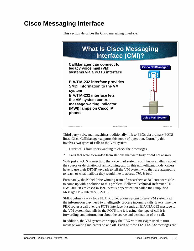
Copyright 2000, Cisco Systems, Inc. Cisco CallManager Services 6-21
Cisco Messaging Interface This section describes the Cisco messaging interface.
? 2000, Cisco Systems, Inc. www.cisco.com CIPT v2.0? -20
What Is Cisco MessagingInterface (CMI)?
CallManager can connect tolegacy voice mail (VM)systems via a POTS interface
Cisco CallManagerCisco CallManager
Voice Mail SystemVoice Mail System
EIA/TIA-232 interface providesSMDI information to the VMsystemEIA/TIA-232 interface letsthe VM system controlmessage waiting indicator(MWI) lamps on Cisco IPphones
Third party voice mail machines traditionally link to PBXs via ordinary POTS lines. Cisco CallManager supports this mode of operation. Normally this involves two types of calls to the VM system:
1. Direct calls from users wanting to check their messages.
2. Calls that were forwarded from stations that were busy or did not answer.
With just a POTS connection, the voice mail system won’t know anything about the source or destination of an incoming call. In this unintelligent mode, callers have to use their DTMF keypads to tell the VM system who they are attempting to reach or what mailbox they would like to access. This is bad.
Fortunately, the Nobel Prize winning team of researchers at Bellcore were able to come up with a solution to this problem. Bellcore Technical Reference TR-NWT-000283 released in 1991 details a specification called the Simplified Message Desk Interface (SMDI).
SMDI defines a way for a PBX or other phone system to give VM systems all the information they need to intelligently process incoming calls. Every time the PBX routes a call over the POTS interface, it sends an EIA/TIA-232 message to the VM system that tells it: the POTS line it is using, the type of call it is forwarding, and information about the source and destination of the call.
In addition, the VM system can supply the PBX with messages used to turn message waiting indicators on and off. Each of these EIA/TIA-232 messages are

6-22 Cisco IP Telephony Copyright 2000, Cisco Systems, Inc.
sent over the same interface. CallManager responds by turning the given lamp on or off.

Copyright 2000, Cisco Systems, Inc. Cisco CallManager Services 6-23
? 2000, Cisco Systems, Inc. www.cisco.com CIPT v2.0? -21
Routed to Voice Mail (VM)System
Message Waiting Indicator (MWI)Or
Messages Button (Cisco IP 7960)
Message Waiting Indicator (MWI)Or
Messages Button (Cisco IP 7960)
Pressing the MWI button on a Cisco IP phone (12 SP+ or 30 VIP), or the Messages button on a Cisco IP phone 7960 results in a call being routed to the voice mail system. While this operation is part of the big picture surrounding CMI, it actually has nothing to do with CMI. It is simply a feature of CallManager that is assigned in the keypad and with directory numbers of the voice mail system.

6-24 Cisco IP Telephony Copyright 2000, Cisco Systems, Inc.
Installing and Configuring
? 2000, Cisco Systems, Inc. www.cisco.com CIPT v2.0? -22
Installing CMI
CMI is installed from the mainCisco CallManager install
CMI is installed from the mainCisco CallManager install
The actual installation process for CMI is simply a matter of selecting the check box in the master installation program. This takes care of copying the CMI executable to the server in question, installing it as a Windows 2000 NT service and registering its performance monitor counters.

Copyright 2000, Cisco Systems, Inc. Cisco CallManager Services 6-25
? 2000, Cisco Systems, Inc. www.cisco.com CIPT v2.0? -23
Windows 2000 NT ServiceManager
After Installation of CMI, you can verify that it is up and running after the server has restarted. To do this:
■ Invoke the Windows 2000 Services Manager, and look for the service. It should be Started.
■ To open Services go to Start>Programs>Administrative Tools>Services.
■ If the Cisco Messaging Interface is not showing “Started”, right click on Cisco Messaging Interface (as shown above).
■ Select start.
■ To change Startup Type, right click on the Cisco Messaging Interface
■ Select properties and select the Startup Type of Automatic, Manual or Disable.

6-26 Cisco IP Telephony Copyright 2000, Cisco Systems, Inc.
Configuring Hardware
? 2000, Cisco Systems, Inc. www.cisco.com CIPT v2.0? -24
Configuring the Hardware
Route a group of POTS ports tothe VM system. This can be
done with an AS-X or VG-200.At this time H.323 interfaces
are NOT supported.
Route a group of POTS ports tothe VM system. This can be
done with an AS-X or VG-200.At this time H.323 interfaces
are NOT supported.
CiscoCallManager Voice Mail System
Connecting to the voice mail system can be done with any sort of POTS port(s). In order to work properly with CMI, control of the POTS ports needs to be accomplished with either the skinny protocol or MGCP. (H.323 devices don’t identify the specific line being used from a group of ports, which means CMI can’t tell the VM system which port is being used for an incoming call.)

Copyright 2000, Cisco Systems, Inc. Cisco CallManager Services 6-27
? 2000, Cisco Systems, Inc. www.cisco.com CIPT v2.0? -25
Configuring the Hardware
Configure the group of ports as a RouteGroup, NOT as individual DNs.
Configure the group of ports as a RouteGroup, NOT as individual DNs.
Due to internal characteristics of Cisco CallManager’s call handling, a group of ports being used with CMI must be configured as a route group. After defining the gateway (analog), add ports, but don’t define DNs for any of the ports.
A common assumption at this point would be to create a range of DNs for Call Forward and Busy through the group. This will NOT work!
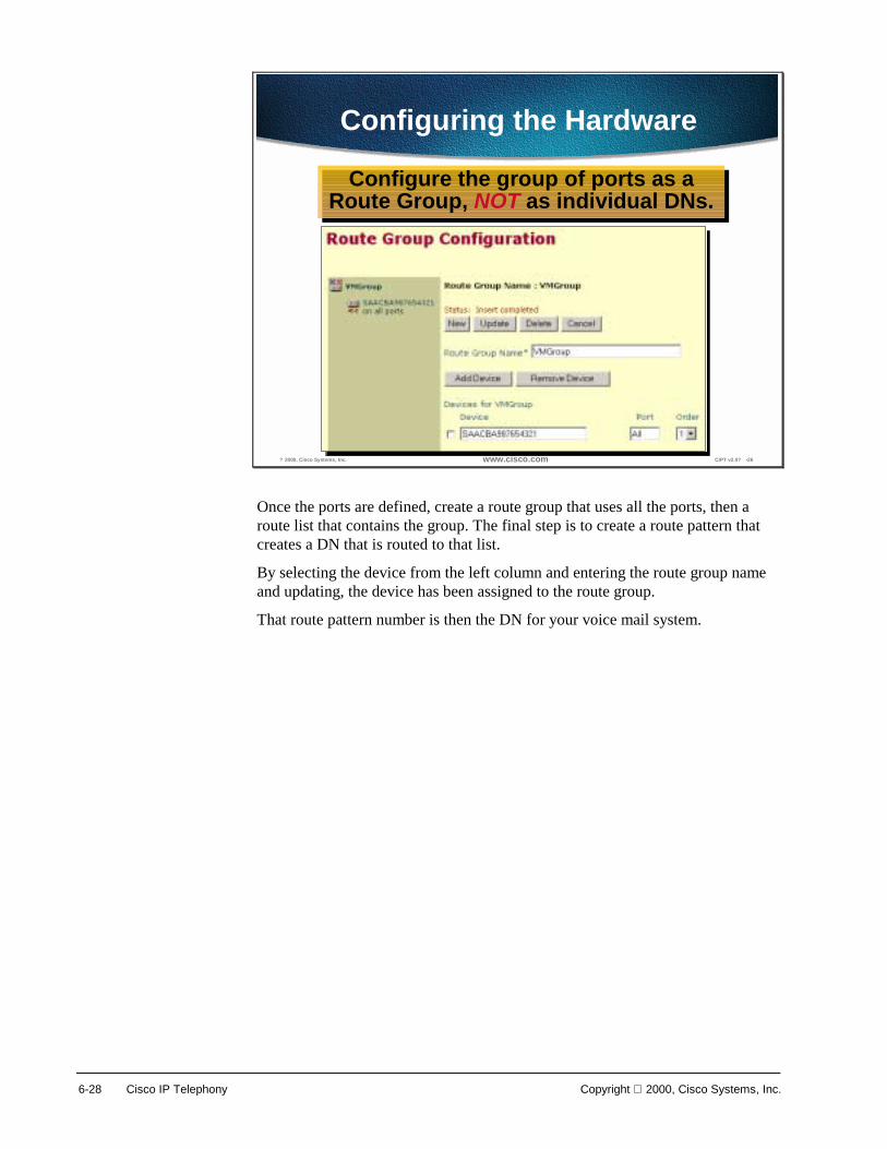
6-28 Cisco IP Telephony Copyright 2000, Cisco Systems, Inc.
? 2000, Cisco Systems, Inc. www.cisco.com CIPT v2.0? -26
Configuring the Hardware
Configure the group of ports as aRoute Group, NOT as individual DNs.
Configure the group of ports as aRoute Group, NOT as individual DNs.
Once the ports are defined, create a route group that uses all the ports, then a route list that contains the group. The final step is to create a route pattern that creates a DN that is routed to that list.
By selecting the device from the left column and entering the route group name and updating, the device has been assigned to the route group.
That route pattern number is then the DN for your voice mail system.

Copyright 2000, Cisco Systems, Inc. Cisco CallManager Services 6-29
? 2000, Cisco Systems, Inc. www.cisco.com CIPT v2.0? -27
Connect the EIA/TIA-232 Ports
Check VM Specs for choice ofnormal or null modem cable.
Check VM Specs for choice ofnormal or null modem cable.
Voice Mail SystemCiscoCallManager
When connecting serial ports between two different PCs, normally a null modem cable is needed. If the VM machine runs on a PC platform, that is what should be used. If the VM system is running on proprietary hardware, consult the manufacturer’s documentation for details on what sort of cable to use.
When using a good breakout box, verify cabling setup by ensuring that valid EIA/TIA-232 levels are present on pins 2 and 3 of either a 9-pin or 25-pin connector.

6-30 Cisco IP Telephony Copyright 2000, Cisco Systems, Inc.
Configuring Software
? 2000, Cisco Systems, Inc. www.cisco.com CIPT v2.0? -28
Configuring theSoftware MI
Use the Cisco CallManagerAdmin web page to createthe service parameters on the appropriate serverUse the Cisco CallManagerAdmin web page to createthe service parameters on the appropriate server
On the Admin web page, pull down the Services menu item and select Cisco Messaging Interface. (Create a new service if necessary at this point.) This brings up the service parameters page. These service parameters contain all the information used to actually configure the CMI service. Understanding the values used for these parameters is all that is needed to get CMI working properly.

Copyright 2000, Cisco Systems, Inc. Cisco CallManager Services 6-31
? 2000, Cisco Systems, Inc. www.cisco.com CIPT v2.0? -29
The Voice Mail NumberThe Voice Mail Number
• CallManagerName• BackupCallManagerName• VoiceMailDN• VoiceMailPartition• RouteFilter• DialingPlan
In order to work properly, CMI has to intercept all calls that are routed to the VM system. Doing this requires the assistance of a Cisco CallManager, as well as a description of the VM directory number.
CMI actually has the names of two Cisco CallManagers: a primary and a backup. If the primary goes down for any reason, CMI will use the backup to intercept calls to the VM box.
Intercepting calls to the VM requires the DN of the route pattern for the voice mail ports, as well as the partition, router filter, and dialing plan for the route filter.
All of these parameters found in the drop down menu Param need to be entered manually—none of them are done automatically. When the Service Parameter is configured it will show up in the Configured Service Parameters drop down menu.

6-32 Cisco IP Telephony Copyright 2000, Cisco Systems, Inc.
? 2000, Cisco Systems, Inc. www.cisco.com CIPT v2.0? -30
The Serial PortThe Serial Port
• SerialPort (COM1)• BaudRate (9600)• Parity (Even)• DataBits (7)• StopBits (1)
These parameters are used to configure the serial port that CMI uses to communicate with the voice mailbox. Each of them has a default value, which is shown above. The COM port being used will be determined by the server hardware. The communication parameters will probably be determined by the VM system hardware. The default values match those given in the SMDI specification, but many systems will elect to user higher baud rates.
Note These settings are the most commonly used, but be sure the check all settings.

Copyright 2000, Cisco Systems, Inc. Cisco CallManager Services 6-33
? 2000, Cisco Systems, Inc. www.cisco.com CIPT v2.0? -31
Number FormattingNumber Formatting
• OutputDnFormat (%010s)• OutputExternalFormat (%010s)• prefix%ns xample: 972%4s
These parameters are used to format the directory numbers sent to the voice mail machine. These formats are used to convert our Directory Numbers (DNs) to mailbox numbers.
The formatting string is passed to a C function called sprintf(). This function has a huge variety of things it can do with a directory number in order to convert it to a mailbox number, but we generally will only use it to do two things: determine the width of the output string; and pre-pend a prefix to the mailbox number.
Based on the North American Numbering Plan (NANP), the formatting string by default is “%10s,” which tells CMI to format the DN into a field 10 characters wide, padded with spaces. Change the “10” to any other numeric value will change the width of the field to the designated value. The width applied here doesn’t include the characters in the prefix.
If you want your VM machine to pad DNs with ‘0s’ instead of spaces, you modify the numeric value to have a leading 0, like this: “%010s.”
Finally, any characters you place ahead of the percent character will just be prepended to the string. In the example shown above, a DN of 1234 would be formatted as 9721234.
Most numbers passed to the VM are formatted using OutputDnFormat. However, calling party DNs that are seven digits or longer are formatted using OutputExternalFormat. Why? This allows you to protect a VM against foolishness caused by outside lines. Many voice mail machines keep track of who the calling party is on a given call. This allows the owner of a mailbox to return calls or send response messages. But we have found that some VMs get confused when Caller ID gives them an outside number that looks as if it might have come from the inside. In those cases, changing OutputExternFormat to something like “0” can often be enough to fix the problem.
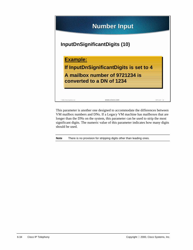
6-34 Cisco IP Telephony Copyright 2000, Cisco Systems, Inc.
? 2000, Cisco Systems, Inc. www.cisco.com CIPT v2.0? -32
Number InputNumber Input
InputDnSignificantDigits (10)
Example:If InputDnSignificantDigits is set to 4A mailbox number of 9721234 isconverted to a DN of 1234
Example:If InputDnSignificantDigits is set to 4A mailbox number of 9721234 isconverted to a DN of 1234
This parameter is another one designed to accommodate the differences between VM mailbox numbers and DNs. If a Legacy VM machine has mailboxes that are longer than the DNs on the system, this parameter can be used to strip the most significant digits. The numeric value of this parameter indicates how many digits should be used.
Note There is no provision for stripping digits other than leading ones.
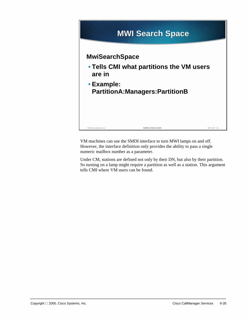
Copyright 2000, Cisco Systems, Inc. Cisco CallManager Services 6-35
? 2000, Cisco Systems, Inc. www.cisco.com CIPT v2.0? -33
MWI Search SpaceMWI Search Space
MwiSearchSpace• Tells CMI what partitions the VM users
are in• Example:
PartitionA:Managers:PartitionB
VM machines can use the SMDI interface to turn MWI lamps on and off. However, the interface definition only provides the ability to pass a single numeric mailbox number as a parameter.
Under CM, stations are defined not only by their DN, but also by their partition. So turning on a lamp might require a partition as well as a station. This argument tells CMI where VM users can be found.

6-36 Cisco IP Telephony Copyright 2000, Cisco Systems, Inc.
? 2000, Cisco Systems, Inc. www.cisco.com CIPT v2.0? -34
Cisco CallManager ParameterCisco CallManager Parameter
VoiceMailThis parameter tells CM what DN to callwhen the MWI button is pressed
VoiceMailThis parameter tells CM what DN to callwhen the MWI button is pressed
Although this CM parameter isn’t actually part of CMI, it has a direct effect on VM users. Normally, when the VM turns on the MWI lamp on a phone, the user will simply press the button to call the VM and begin listening to messages.
When the user presses the MWI button, CM looks at its service parameter called VoiceMail to determine where to route the call. This parameter needs to be set up in each CM that is supporting VM users.

Copyright 2000, Cisco Systems, Inc. Cisco CallManager Services 6-37
Monitoring and Troubleshooting
? 2000, Cisco Systems, Inc. www.cisco.com CIPT v2.0? -35
Normal OperationsNormal Operations
• Verify that CMI is running using the Windows2000 NT Service Manager
• Monitor with Performance Monitor
Regardless of whether anything is happening, it always possible to verify that CMI is at least functional by looking at the Heartbeat. This performance monitor counter should be incrementing once a second as long as CMI is running.
The inbound and outbound message counts are a way to track the number of messages that have been sent and received between the CM and VM since the service was started. Perhaps a better way to track the activity of CMI is with the 24-hour rolling count.
To get to Performance Monitor go to Start>Programs>Administrative Tools>Performance.

6-38 Cisco IP Telephony Copyright 2000, Cisco Systems, Inc.
? 2000, Cisco Systems, Inc. www.cisco.com CIPT v2.0? -36
View EventLog ApplicationView EventLog Application
Check serial portCheck VoiceMailDNTrace ormally set to
ERRORFor more info, set toDETAILEDView files:CSUMI*.TXT
Check serial portCheck VoiceMailDNTrace ormally set to
ERRORFor more info, set toDETAILEDView files:CSUMI*.TXT
Most serious errors in the operation of CMI will be reflected with an error message in the application event log. If the CMI is not working at all, this should be the first place to go.
The two most common problems that keep CMI from working are the failure to open the serial port, and problems intercepting the voice mail DN.

Copyright 2000, Cisco Systems, Inc. Cisco CallManager Services 6-39
? 2000, Cisco Systems, Inc. www.cisco.com CIPT v2.0? -37
Detailed Trace Log
The figure above is an example of a detailed trace log. The detailed trace log tends to be a bit cluttered, but with a careful read it will usually highlight the source of any difficulties.
Trace is started from the Cisco CallManager Administration and from the menu go to System>Trace. It is recommended to turn on user mask 3-13.

6-40 Cisco IP Telephony Copyright 2000, Cisco Systems, Inc.
Cisco IP Voice Media Streaming Application This section describes the Cisco IP Voice Media Streaming application.
? 2000, Cisco Systems, Inc. www.cisco.com CIPT v2.0? -39
What Is the MediaApplication?
What Is the MediaApplication?
• Combines the MTP and conferencebridge functionality into one Windows2000 NT service and device driver
• Adds conference bridge support to aCallManager
• Adds media termination point supportto a CallManager
The Cisco IP Voice Media Streaming Application runs as an NT service (ipvmsapp.exe). The service is responsible for forwarding the Cisco CallManager messages to the driver and for device recovery.
The device driver runs as a non-plug and play kernel mode driver (ipvms.sys). and does all of the RTP streaming.
The Cisco IP Voice Media Streaming application adds software conference bridge and media termination support for Cisco CallManager.
Only G.711 µ−law and a-law streams are supported.
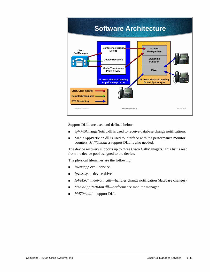
Copyright 2000, Cisco Systems, Inc. Cisco CallManager Services 6-41
© 2000, Cisco Systems, Inc. www.cisco.com CIPT v2.0—6-40
Software Architecture
Cisco CallManager
Conference Bridge Device
Device Recovery
Media Termination Point Device
IP Voice Media Streaming App (ipvmsapp.exe)
Stream Management
Switching Function
Mixer
IP Voice Media Streaming Driver (ipvms.sys)
Register/Unregister
Start, Stop, Config
RTP Streaming
Support DLLs are used and defined below:
■ IpVMSChangeNotify.dll is used to receive database change notifications.
■ MediaAppPerfMon.dll is used to interface with the performance monitor counters. Mtl70mt.dll a support DLL is also needed.
The device recovery supports up to three Cisco CallManagers. This list is read from the device pool assigned to the device.
The physical filenames are the following:
■ Ipvmsapp.exe—service
■ Ipvms.sys—device driver
■ IpVMSChangeNotify.dll—handles change notification (database changes)
■ MediaAppPerfMon.dll—performance monitor manager
■ Mtl70mt.dll—support DLL
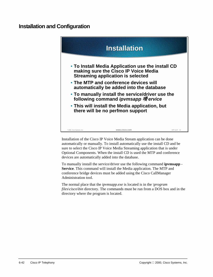
6-42 Cisco IP Telephony Copyright 2000, Cisco Systems, Inc.
Installation and Configuration
? 2000, Cisco Systems, Inc. www.cisco.com CIPT v2.0? -41
InstallationInstallation
• To Install Media Application use the install CDmaking sure the Cisco IP Voice MediaStreaming application is selected
• The MTP and conference devices willautomatically be added into the database
• To manually install the service/driver use thefollowing command ipvmsapp ervice
• This will install the Media application, butthere will be no perfmon support
Installation of the Cisco IP Voice Media Stream application can be done automatically or manually. To install automatically use the install CD and be sure to select the Cisco IP Voice Media Streaming application that is under Optional Components. When the install CD is used the MTP and conference devices are automatically added into the database.
To manually install the service/driver use the following command ipvmsapp - Service. This command will install the Media application. The MTP and conference bridge devices must be added using the Cisco CallManager Administration tool.
The normal place that the ipvmsapp.exe is located is in the \program files\cisco\bin directory. The commands must be run from a DOS box and in the directory where the program is located.
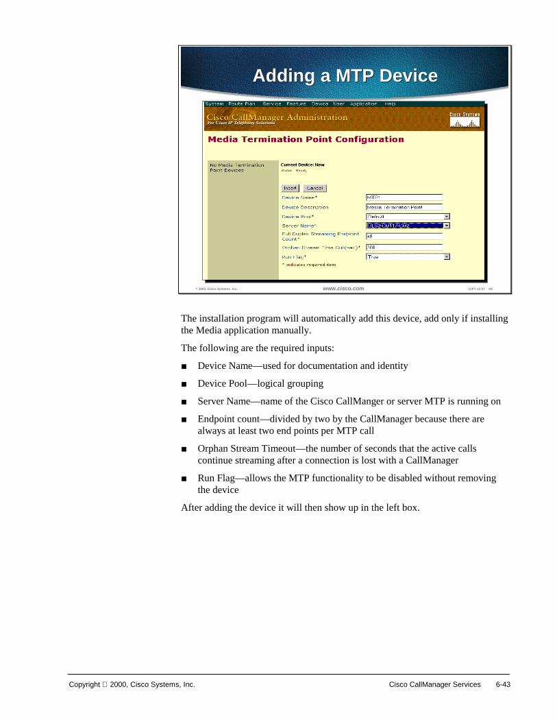
Copyright 2000, Cisco Systems, Inc. Cisco CallManager Services 6-43
? 2000, Cisco Systems, Inc. www.cisco.com CIPT v2.0? -42
Adding a MTP DeviceAdding a MTP Device
The installation program will automatically add this device, add only if installing the Media application manually.
The following are the required inputs:
■ Device Name—used for documentation and identity
■ Device Pool—logical grouping
■ Server Name—name of the Cisco CallManger or server MTP is running on
■ Endpoint count—divided by two by the CallManager because there are always at least two end points per MTP call
■ Orphan Stream Timeout—the number of seconds that the active calls continue streaming after a connection is lost with a CallManager
■ Run Flag—allows the MTP functionality to be disabled without removing the device
After adding the device it will then show up in the left box.

6-44 Cisco IP Telephony Copyright 2000, Cisco Systems, Inc.
? 2000, Cisco Systems, Inc. www.cisco.com CIPT v2.0? -43
Adding a Conference BridgeDevice
Adding a Conference BridgeDevice
The installation program will automatically add this device. Only add it by installing the Media application manually.
The Cisco CallManager divides the endpoint count by three because there are always at least three end points per conference bridge call.
Orphan Stream Timeout is the number of seconds that the active calls continue streaming after a connection is lost with a Cisco CallManager.
Run Flag allows the conference bridge functionality to be disabled without removing the device. Be aware of the conference bridge parameters selection.
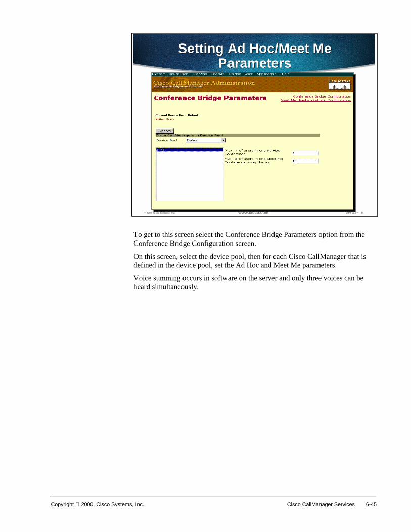
Copyright 2000, Cisco Systems, Inc. Cisco CallManager Services 6-45
? 2000, Cisco Systems, Inc. www.cisco.com CIPT v2.0? -44
Setting Ad Hoc/Meet MeParameters
Setting Ad Hoc/Meet MeParameters
To get to this screen select the Conference Bridge Parameters option from the Conference Bridge Configuration screen.
On this screen, select the device pool, then for each Cisco CallManager that is defined in the device pool, set the Ad Hoc and Meet Me parameters.
Voice summing occurs in software on the server and only three voices can be heard simultaneously.

6-46 Cisco IP Telephony Copyright 2000, Cisco Systems, Inc.
Monitoring and Troubleshooting
? 2000, Cisco Systems, Inc. www.cisco.com CIPT v2.0? -45
Monitoring andTroubleshooting Tools
Monitoring andTroubleshooting Tools
• Performance Monitor• Event log• Windows 2000 Service Manager• Cisco CallManager trace
If a hardware transcoding application or conference bridge isregistered with the same Cisco CallManager as the Media applicationthen the Media application device is disabled. If the hardwareresource un-registers or is shut down the Media applicationresources will be unavailable until the devices are reset.
If a hardware transcoding application or conference bridge isregistered with the same Cisco CallManager as the Media applicationthen the Media application device is disabled. If the hardwareresource un-registers or is shut down the Media applicationresources will be unavailable until the devices are reset.
The monitoring and trouble shooting tools for the Cisco IP Voice Media Streaming application are from the Windows 2000 server and Cisco CallManager. The following are the tools used to monitor and troubleshoot:
■ Performance monitor—used to see if the Cisco CallManager has the Cisco IP Voice Media Application resources available for use.
■ Event log—used to see any Cisco IP Voice Media Streaming application entries.
■ Windows 2000 Service Manager—used to verify that the Cisco IP Voice Media Streaming application service and device driver are running.
■ Cisco CallManager Trace—is used to see what the Cisco CallManager thinks is happening.
If hardware transcoding application or conference bridge is registered with the same Cisco CallManager as the Cisco IP Voice Media Streaming application, then the Media application is disabled. If the hardware resource un-registers or is shut down the Media application resources will be unavailable until the devices are reset.

Copyright 2000, Cisco Systems, Inc. Cisco CallManager Services 6-47
? 2000, Cisco Systems, Inc. www.cisco.com CIPT v2.0? -46
Viewing Performance MonitorCounters
Viewing Performance MonitorCounters
This screen shows all of the Cisco CallManager performance counters. To monitor and troubleshoot for the Cisco IP Voice Media Streaming application the counters that help are:
■ MediaTermPointsAvailable
■ UnicastAvailableConferences
These two counters identify whether the Cisco IP Voice Media application resources (devices) are registered with the Cisco CallManager.
The other counters on this list identify MTP and conference bridge resources being used and completed.

6-48 Cisco IP Telephony Copyright 2000, Cisco Systems, Inc.
? 2000, Cisco Systems, Inc. www.cisco.com CIPT v2.0? -47
Viewing Event Log EntriesViewing Event Log Entries
Event log is a monitoring and troubleshooting tool of the Windows 2000 server and can provide details about events related to the Cisco IP Voice Media Streaming application.
To open it go to Start>Programs>Administrative Tools>Event Viewer>Application Log. Right click on an event and select properties to get an expanded view of the event.

Copyright 2000, Cisco Systems, Inc. Cisco CallManager Services 6-49
? 2000, Cisco Systems, Inc. www.cisco.com CIPT v2.0? -48
Verify Service Is RunningVerify Service Is Running
The Windows 2000 Service Manager is used to verify that the Cisco IP Media Streaming application service and driver are running.
To open it go to Start>Programs>Administrative Tools>Computer Management>Services.

6-50 Cisco IP Telephony Copyright 2000, Cisco Systems, Inc.
? 2000, Cisco Systems, Inc. www.cisco.com CIPT v2.0? -49
Check if Device Driver IsRunning
Check if Device Driver IsRunning
To open it go to Start>Programs>Administrative Tools>Computer Management> Device Manager>Non-Plug and Play Drivers. Right-click on the Cisco IP Voice Media Streaming application for a detailed view of the properties.

Copyright 2000, Cisco Systems, Inc. Cisco CallManager Services 6-51
? 2000, Cisco Systems, Inc. www.cisco.com CIPT v2.0? -50
Cisco IP Voice MediaApplication Trace
Cisco IP Voice MediaApplication Trace
The detailed trace log tends to be a bit cluttered, but by reading it carefully it will usually highlight the source of any difficulties. In Cisco CallManager Administration go to the Service in the tool bar and select Trace from the drop down menu. Set the level to detailed with all mask bits turned on and make sure the EventLog check box is selected for entries to be placed into the event log. Select the file option and that a valid filename/path is entered. After making any changes the Update button must be selected for the changes to take affect.
The following page includes samples of trace log files.

6-52 Cisco IP Telephony Copyright 2000, Cisco Systems, Inc.
? 2000, Cisco Systems, Inc. www.cisco.com CIPT v2.0? -51
Media App Startup andDatabase ConfigurationMedia App Startup andDatabase Configuration
Sample of Media App StartupCisco Media App| CIpVMSMgr::CIpVMSMgr Cisco IP Voice Media Streaming Application [3.0(2.1)] -
StartingCisco Media App|-->CIpVMSMgr::IsDriverPresentCisco Media App| CIpVMSMgr::IsDriverPresent Driver is Present, IP Addr = 1122442412Cisco Media App|<--CIpVMSMgr::IsDriverPresent
Sample of database configuration parametersCisco Media App|-->CIpVMSMgr::ReadConfigurationCisco Media App| CIpVMSMgr::ReadConfiguration MTP DeviceName = MTP_dls2-cm118-Cisco Media App| CIpVMSMgr::ReadConfiguration MTP ServerName[0] = dls2-cm118-app1, Port = 2000Cisco Media App| CIpVMSMgr::ReadConfiguration MTP Number of Calls = 48Cisco Media App| CIpVMSMgr::ReadConfiguration MTP Orphaned Stream Timeout (sec) = 300Cisco Media App| CIpVMSMgr::ReadConfiguration MTP Run Flag = 1Cisco Media App| CIpVMSMgr::ReadConfiguration CFB DeviceName = CFB_dls2-cm118-Cisco Media App| CIpVMSMgr::ReadConfiguration CFB ServerName[0] = dls2-cm118-app1, Port = 2000Cisco Media App| CIpVMSMgr::ReadConfiguration CFB Number of Parties = 48Cisco Media App| CIpVMSMgr::ReadConfiguration CFB Orphaned Stream Timeout (sec) = 300Cisco Media App| CIpVMSMgr::ReadConfiguration CFB Run Flag = 1Cisco Media App|<--CIpVMSMgr::ReadConfiguration
Sample of database configuration parametersCisco Media App|-->CIpVMSMgr::ReadConfigurationCisco Media App| CIpVMSMgr::ReadConfiguration MTP DeviceName = MTP_dls2-cm118-Cisco Media App| CIpVMSMgr::ReadConfiguration MTP ServerName[0] = dls2-cm118-app1, Port = 2000Cisco Media App| CIpVMSMgr::ReadConfiguration MTP Number of Calls = 48Cisco Media App| CIpVMSMgr::ReadConfiguration MTP Orphaned Stream Timeout (sec) = 300Cisco Media App| CIpVMSMgr::ReadConfiguration MTP Run Flag = 1Cisco Media App| CIpVMSMgr::ReadConfiguration CFB DeviceName = CFB_dls2-cm118-Cisco Media App| CIpVMSMgr::ReadConfiguration CFB ServerName[0] = dls2-cm118-app1, Port = 2000Cisco Media App| CIpVMSMgr::ReadConfiguration CFB Number of Parties = 48Cisco Media App| CIpVMSMgr::ReadConfiguration CFB Orphaned Stream Timeout (sec) = 300Cisco Media App| CIpVMSMgr::ReadConfiguration CFB Run Flag = 1Cisco Media App|<--CIpVMSMgr::ReadConfiguration
The above samples of the trace of Media App Startup and database configuration parameters are small snapshots of the entire trace and highlight the parts of the trace we are most concerned with when troubleshooting or gathering information for troubleshooting.
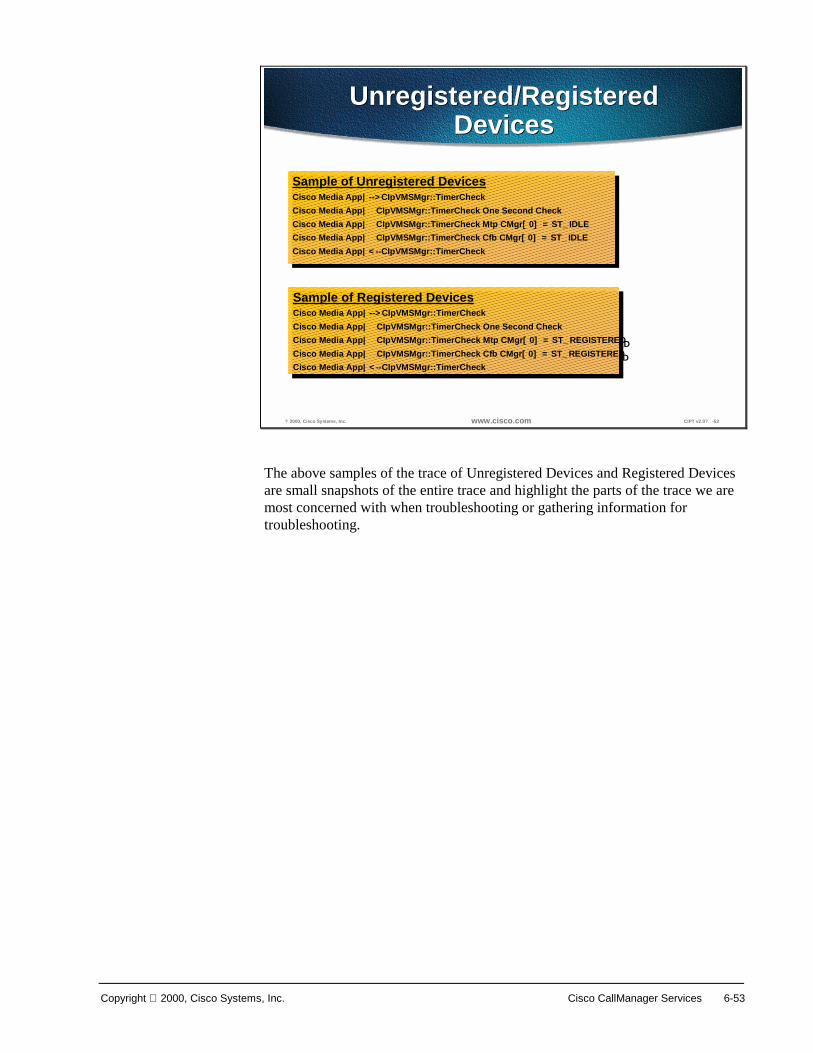
Copyright 2000, Cisco Systems, Inc. Cisco CallManager Services 6-53
? 2000, Cisco Systems, Inc. www.cisco.com CIPT v2.0? -52
Unregistered/RegisteredDevices
Unregistered/RegisteredDevices
Sample of Unregistered DevicesCisco Media App|-->CIpVMSMgr::TimerCheckCisco Media App| CIpVMSMgr::TimerCheck One Second CheckCisco Media App| CIpVMSMgr::TimerCheck Mtp CMgr[0] = ST_IDLECisco Media App| CIpVMSMgr::TimerCheck Cfb CMgr[0] = ST_IDLECisco Media App|<--CIpVMSMgr::TimerCheck
Sample of Unregistered DevicesCisco Media App|-->CIpVMSMgr::TimerCheckCisco Media App| CIpVMSMgr::TimerCheck One Second CheckCisco Media App| CIpVMSMgr::TimerCheck Mtp CMgr[0] = ST_IDLECisco Media App| CIpVMSMgr::TimerCheck Cfb CMgr[0] = ST_IDLECisco Media App|<--CIpVMSMgr::TimerCheck
Sample of Registered DevicesCisco Media App|-->CIpVMSMgr::TimerCheckCisco Media App| CIpVMSMgr::TimerCheck One Second CheckCisco Media App| CIpVMSMgr::TimerCheck Mtp CMgr[0] = ST_REGISTEREDCisco Media App| CIpVMSMgr::TimerCheck Cfb CMgr[0] = ST_REGISTEREDCisco Media App|<--CIpVMSMgr::TimerCheck
Sample of Registered DevicesCisco Media App|-->CIpVMSMgr::TimerCheckCisco Media App| CIpVMSMgr::TimerCheck One Second CheckCisco Media App| CIpVMSMgr::TimerCheck Mtp CMgr[0] = ST_REGISTEREDCisco Media App| CIpVMSMgr::TimerCheck Cfb CMgr[0] = ST_REGISTEREDCisco Media App|<--CIpVMSMgr::TimerCheck
The above samples of the trace of Unregistered Devices and Registered Devices are small snapshots of the entire trace and highlight the parts of the trace we are most concerned with when troubleshooting or gathering information for troubleshooting.

6-54 Cisco IP Telephony Copyright 2000, Cisco Systems, Inc.
Summary This section summarizes the concepts you learned in this chapter.
? 2000, Cisco Systems, Inc. www.cisco.com CIPT v2.0? -53
SummarySummary
• Cisco TFTP allows the devices to get informationfrom the database without having to access itdirectly and allows the executables to be updatedautomatically.
• Cisco Messaging Interface allows CiscoCallManager to connect to third-party voice mailsystems.
• Cisco IP Voice Media Streaming applicationsupplies MTP/conference bridge resources to aCallManager.
The Cisco Trivial File Transfer Protocol (Cisco TFTP) is a Windows NT 2000 service. The Cisco TFTP service builds configuration files from information found in the database. Cisco TFTP serves configuration, executable, and ringer files consistent with ITU RFC 1350. Cisco TFTP allows executables to be updated automatically.
The Cisco Messaging Interface allows Cisco CallManager to connect to third-party voice mail systems using the POTS interface with SMDI.
The Cisco IP Voice Media Streaming application supplies software MTP and conference bridge resources for a Cisco IP telephony solution. This can be used if there are no hardware MTP (transcoding)/conference resources in a CIPT solution.

Copyright 2000, Cisco Systems, Inc. Cisco CallManager Services 6-55
Review Questions Answer the following questions.
? 2000, Cisco Systems, Inc. www.cisco.com CIPT v2.0? -54
Review QuestionsReview Questions
1. Why would I want more than oneTFTP server in a cluster?
2. Should the group of ports used forvoice messaging be configured asdirectory numbers or a route group?
3. If software and hardwareMTP/conferencing are being used,which does Cisco CallManagerprefer?
Q1) If the DHCP can only point to one Cisco TFTP Server, why would there be a need for more than one Cisco TFTP?
Q2) When using Cisco Messaging Interface to connect to a third party voice mail and hardware is involved, should the group of ports used for voice messaging be configured as individual directory numbers or a route group?
Q3) If a Cisco CallManager has the Cisco Voice Media Streaming application running for software MTP/conferencing and hardware transcoding/conferencing resources configured, which does the Cisco CallManager use, hardware or software?

7
Overview A dial plan is essentially the “front end” that allows users to dial one another. The goal of a successful dial plan is to provide diverse call routing and provide for ease of dialing for users. Often customers require abbreviated dialing as well as supporting redundant paths that are transparent to the calling party. The dial plan in Call Manager 3.0 is enhanced to allow for greater scalability, flexibility and ease of use. Tighter integration of Call Manger and IOS Gateways will allow for larger AVVID deployments.
This chapter includes the following topics:
■ Objectives
■ Dial Plan Architecture
■ Special Dial String Considerations
■ Configuring Dial Plan Groups and Calling Restrictions
■ Campus and Dial Plan Guidelines and Considerations
■ Summary
■ Review Questions
7-2 Cisco IP Telephony Copyright 2000, Cisco Systems, Inc.
Objectives This section lists the chapter objectives.
? 2000, Cisco Systems, Inc. www.cisco.com CIPT v2.0? -3
ObjectivesObjectives
Upon completion of this chapter, you will beable to perform the following tasks:• Identify and describe the dial plan architecture• Identify and follow design guidelines for dial
plan architecture• Identify special dial string considerations• Configure dial plan groups and calling
restrictions
Upon completion of this chapter, you will be able to complete the following tasks:
■ Given a list of components of the dial plan architecture, identify and describe the functional components of the dial plan architecture.
■ Given a list of design guidelines for dial plan architecture, identify and construct a dial plan.
■ Given a list of dial string considerations identify the special dial string considerations described in this chapter.
■ Given a case study and calling characteristics, configure dial plan groups and calling restrictions.

Copyright 2000, Cisco Systems, Inc. Dial Plan Architecture 7-3
Visual Objective This section shows the visual objective of a dial plan.
? 2000, Cisco Systems, Inc. www.cisco.com CIPT v2.0? -4
PSTN
IP WAN
A
A
V
V
Gatekeeper(s)
Primary Voice PathPrimary Voice PathStrip ? 2? and deliver
61111 to remote Call Manager
Secondary Voice PathSecondary Voice PathPre-pend ? 408? and send to PSTN
(408) 526-XXXX5 Digit Internal Dialing
Users required to dial7 digits for Intersite calls
? 26-1111�
Dial Plan Visual Objective
San Jose
Philadelphia(215) 555-XXXX
5 Digit Internal Dialing
The figure above depicts the goal of a well-designed dial plan where voice calls transparently use the IP WAN as the first choice and use the PSTN transparently to the user if the IP WAN is down or unavailable.

7-4 Cisco IP Telephony Copyright 2000, Cisco Systems, Inc.
Dial Plan Architecture This section gives an explanation of the dial plan architecture and functional components.
? 2000, Cisco Systems, Inc. www.cisco.com CIPT v2.0? -5
Internal vs. External ReachabilityInternal vs. External Reachability
CallManager
1000
Router/GWV
PSTN
IPWAN
1001
1002
Reachability of Internal Phonesachieved by it DN (Directory Number)DN (Directory Number)
being specifically configured in the CallManager Database
Reachability of Remote IP WAN Sitesand the PSTN achieved by configuringRoute PatternsRoute Patterns that summarize E.164
address ranges configured in the Database
215-555-XXXX
The CallManager’s dial plan architecture is setup to handle generally two types of calls:
■ Internal calls to IP phones registered to the CallManager cluster itself
■ External calls via a PSTN gateway or to another CallManager cluster via the IP WAN
The dial plan for internal calls to IP phones registered with a CallManager cluster is fairly simple in the fact that when an IP phone is initially configured it is assigned a phone number and the IP phone maintains that number wherever it resides. Whenever the IP phone registers with the CallManager cluster it effectively updates the CallManager cluster dynamically with its new IP address while maintaining its same phone number. The internal dial length (number of digits dialed) for internal calls may be configured as desired. Note that not only IP phones may be reached in this manner. Other devices that register with CallManager and maintain a DN (Directory Number) can include soft phones, and analog phones attached to MGCP/skinny based gateways.
When configuring the CallManager to handle external calls then the use of the route pattern is required. The route pattern is in most cases used for directing calls out to a PSTN gateway or in the case of an IP WAN call to a remote CallManager. The CallManager 3.0 dial plan architecture is a three tiered decision tree that allows for multiple routes to be taken for a given dialed number as well as digit manipulation based on the customer network

Copyright 2000, Cisco Systems, Inc. Dial Plan Architecture 7-5
requirements. Such capabilities such as trunk groups can be configured for gateway redundancy and a form of least cost routing. Digit manipulation is the task of adding or subtracting digits from the original dialed number to accommodate the users dial habit or gateway needs.
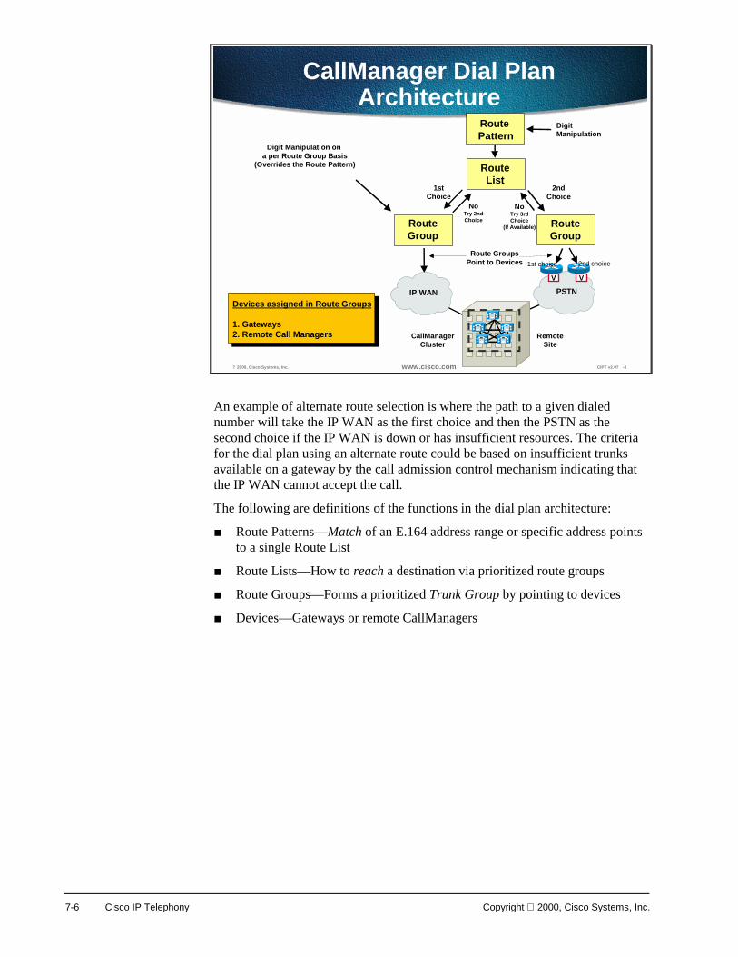
7-6 Cisco IP Telephony Copyright 2000, Cisco Systems, Inc.
? 2000, Cisco Systems, Inc. www.cisco.com CIPT v2.0? -6
Route Pattern
RouteList
RouteGroup
1stChoice
2ndChoice
PSTNIP WAN
RouteGroup
NoTry 2ndChoice
NoTry 3rdChoice
(If Available)
Digit Manipulation on a per Route Group Basis
(Overrides the Route Pattern)
Digit Manipulation
V V
CallManagerCluster
RemoteSite
A
Route GroupsPoint to Devices
Devices assigned in Route Groups
1. Gateways2. Remote Call Managers
CallManager Dial PlanArchitecture
1st choice 2nd choice
An example of alternate route selection is where the path to a given dialed number will take the IP WAN as the first choice and then the PSTN as the second choice if the IP WAN is down or has insufficient resources. The criteria for the dial plan using an alternate route could be based on insufficient trunks available on a gateway by the call admission control mechanism indicating that the IP WAN cannot accept the call.
The following are definitions of the functions in the dial plan architecture:
■ Route Patterns—Match of an E.164 address range or specific address points to a single Route List
■ Route Lists—How to reach a destination via prioritized route groups
■ Route Groups—Forms a prioritized Trunk Group by pointing to devices
■ Devices—Gateways or remote CallManagers

Copyright 2000, Cisco Systems, Inc. Dial Plan Architecture 7-7
? 2000, Cisco Systems, Inc. www.cisco.com CIPT v2.0? -8
Dial Plan ConfigurationInterface
Dial Plan ConfigurationInterface
In the Cisco CallManager interface, you will go to the Route Plan heading and select Route Group, Route List, or route pattern to configure the route pattern.

7-8 Cisco IP Telephony Copyright 2000, Cisco Systems, Inc.
? 2000, Cisco Systems, Inc. www.cisco.com CIPT v2.0? -7
Route Pattern Configuration OrderRoute Pattern Configuration Order
1. Devices2. Route group3. Route list4. Route pattern
The order you would configure your route pattern is shown in the following list:
1. Devices
2. Route group
3. Route list
4. Route pattern

Copyright 2000, Cisco Systems, Inc. Dial Plan Architecture 7-9
? 2000, Cisco Systems, Inc. www.cisco.com CIPT v2.0? -16
Device Configuration Characteristics(For a Remote Call Manager)
Device Configuration Characteristics(For a Remote Call Manager)
Enabling device asGatekeeper Controlled
Gatekeeper IPAddress
Remote H.323 Device(Call Manager)
Defining H.323 GWas an nter-Cluster Trunk�
(Remote Call Manager)
Device Pool to define CODEC used for calls to this device
Where this devicemay call
(Incoming Calls)
Where this devicemay call
(Incoming Calls)
The figure above identifies the device configuration characteristics for a remote CallManager. The remote CallManager needs to be defined as an H.323 gateway in an Inter-Cluster Trunk. The device name is the remote H.323 device that is the CallManager. The device pool is used to define the codec used for calls to this device, remote CallManager. The Gatekeeper Registration has the device and remote CallManager is enabled as Gatekeeper Controlled. In the Gatekeeper Name area, you will enter the IP address of the gatekeeper and primary CallManager. Also in this example the Calling Search Space is defined as unrestricted. The Calling Search Space is used to define where this device may call.

7-10 Cisco IP Telephony Copyright 2000, Cisco Systems, Inc.
Route Group
? 2000, Cisco Systems, Inc. www.cisco.com CIPT v2.0? -12
Route Grouprioritized Trunk Group�
Route Grouprioritized Trunk Group�
Device(s) that the Route Group points to
Device(s) that the Route Group points to
Route groups control specific devices, which are gateways. Gateways may be skinny, MGCP or H.323 based. Endpoints such as NetMeeting clients or remote Call Managers across the IP WAN are configured as H.323 gateways. The route group points to one or more devices and can select the devices for call routing based on preference. The route group can direct all calls to the primary device and then utilize the secondary devices when the primary is unavailable. This serves effectively as a trunk group. One or more route lists can point to the same route group. All devices in a given route group have the same characteristics such as path and digit manipulation. As mentioned above route groups have the ability of performing digit manipulation that will over ride what was performed in the route pattern.

Copyright 2000, Cisco Systems, Inc. Dial Plan Architecture 7-11
? 2000, Cisco Systems, Inc. www.cisco.com CIPT v2.0? -13
J IPWAN? Route GroupJ IPWAN? Route Group
Discard Access CodeDiscard Access Code
The figure above shows settings that will override the settings of the Route Pattern Page for the “SJ IPWAN” Route Group. For the example above, the Called Party Transformations will discard digits of the access code.

7-12 Cisco IP Telephony Copyright 2000, Cisco Systems, Inc.
? 2000, Cisco Systems, Inc. www.cisco.com CIPT v2.0? -14
HL PSTN? Route Group
Pre-pend ? 408�Pre-pend ? 408�
The figure above shows the digits of 1408 will be pre-pended to the number if the called party is has the prefix digits of 1601. The “PHL PSTN” Route Group is devices.

Copyright 2000, Cisco Systems, Inc. Dial Plan Architecture 7-13
? 2000, Cisco Systems, Inc. www.cisco.com CIPT v2.0? -15
RouteGroup
Skinny Based
DT-24+Cat 6K GW
AT + AS GW
V
MGCP Based
VG200
V
H.323 Based
All IOS GW
H.323 Based
Remote CallManager
Configured as:Configured as:Device Protocol=H.225Device Protocol=H.225
Configured as:Configured as:Device Protocol=Inter-cluster TrunkDevice Protocol=Inter-cluster Trunk
Typical Route Group Device Types
Devices are associated with gateways or remote CallManagers. Within the device configuration information on how the call is actually placed is defined. The figure above illustrates the types of devices that route groups can point to in order to intelligently deliver calls.
■ An H.323 gateway may be configured to be gatekeeper controlled. This means that before a call is placed to an H.323 device it must successfully query the gatekeeper first.
■ The codec used by calls to the device may be selected by placing the device in a region, which determines the codec to be used.
■ Multiple clusters for inbound and outbound calls may share H.323 gateways where as MGCP and skinny based gateways are dedicated to a single CallManager cluster.
The route pattern dial structure is typically used when IP phone calls are destined to go to gateways or remote CallManagers via H.323. In these instances alternate routes may be taken in the event the primary path to a destination is not available. This is the model used in the multi-site IP WAN with the distributed call processing model where all inter-site calls will take the IP WAN as the primary path and the PSTN as the secondary path.
Calls between IP phones that reside on the same CallManager/cluster do not utilize the route pattern dial structure and therefore cannot utilize alternate routes if connectivity is down between them. In all likely hood if IP connectivity is down between to IP phones then there are good chances that one of the phones has lost connectivity to a CallManager and cannot even place a call. A good example of this is when using multi-site WAN deployments with centralized call processing. In this case there is no alternate routing between sites.

7-14 Cisco IP Telephony Copyright 2000, Cisco Systems, Inc.
Route List
? 2000, Cisco Systems, Inc. www.cisco.com CIPT v2.0? -11
Route List ConfigurationRoute List Configuration
Route Groups used to reach Route Pattern(Each Route Group has unique Digit Manipulation)
1st Choice for San Jose - SJ IPWAN2nd Choice for San Jose - PSTN
Route Groups used to reach Route Pattern(Each Route Group has unique Digit Manipulation)
1st Choice for San Jose - SJ IPWAN2nd Choice for San Jose - PSTN
The CallManager 2.4 term route point has been replaced by the route list in CallManager 3.0 while performing much of the same role. A route list defines the way a call is routed. Route lists are configured to point to one or more route groups, which effectively serve the purpose of trunk groups. The route list sends a given call to a route group in a configured order of preference. This could be where the primary route group may offer a lower cost for calls where as the secondary route groups will only be used if the primary is unavailable due to an all trunks busy condition or insufficient IP WAN resources.

Copyright 2000, Cisco Systems, Inc. Dial Plan Architecture 7-15
Route Pattern A route pattern is an address. Some addresses, such as directory numbers match only one dialed digit string. Other addresses such as gateway route patterns, match a range of dialed digit strings.
? 2000, Cisco Systems, Inc. www.cisco.com CIPT v2.0? -9
Route Pattern ConfigurationRoute Pattern Configuration
Partition(WHO can reach ? 2.XXXX�
Route List(Defines HOW to reach ? 2.XXXX?
Route PatternDigits left of *.* are the ccess Code�
Digit manipulation
The Route Pattern identifies a dialed number (E.164 address in North America) and uses the underlying Route List and Route Group configurations to determine how to route the call.
When a Route Pattern matches a dialed number, it will hand the call to the Route List associated with the Route Pattern. The Route List will then make the decision as to which downstream route groups (trunk groups) to send the call to based on the ordered priority. Prior to handing the call to the Route List, digit manipulation will occur depending if digits need to be added or removed from the matched Route Pattern.
The digit manipulation occurs in the Route Pattern for outbound calls only before it gets sent to the Route List + Route Groups. Note that individual downstream route groups may have unique digit manipulations for the same Route Pattern. This is extremely useful where different routes to a given dialed number may require different manipulations. An example of this would be where users were required to dial seven digits to reach a remote location that has a four digit internal dial plan length. Across the IP WAN the first three digits may have to be removed in order to deliver the last four digits to the remote Call Manager in its native internal dial string length. If the IP WAN was down or could not accept additional voice calls then the dialed seven digits would have to be pre-pended with the area code in order to reach the called party via the PSTN. A route pattern is associated with only one route list.
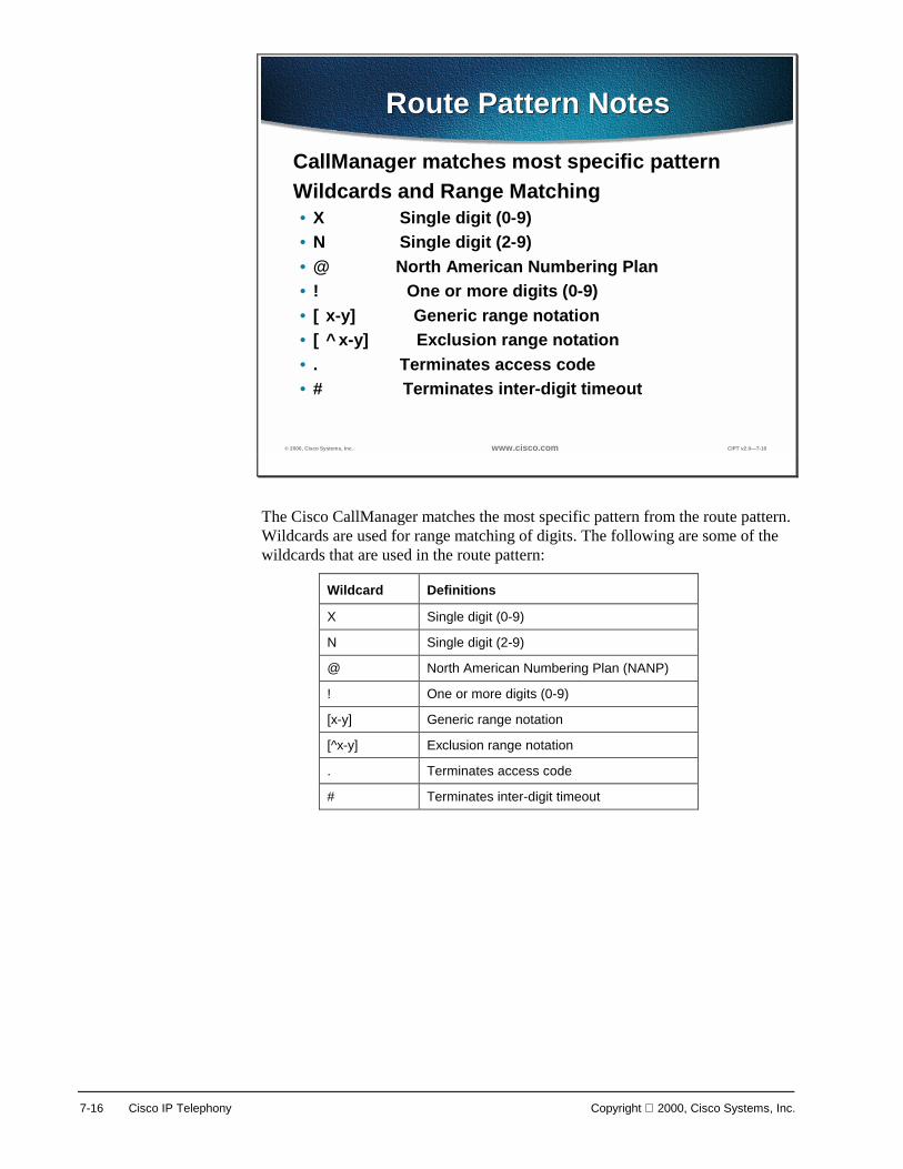
7-16 Cisco IP Telephony Copyright 2000, Cisco Systems, Inc.
© 2000, Cisco Systems, Inc. www.cisco.com CIPT v2.0—7-16
Route Pattern NotesRoute Pattern Notes
CallManager matches most specific patternWildcards and Range Matching• X Single digit (0-9)• N Single digit (2-9)• @ North American Numbering Plan• ! One or more digits (0-9)• [x-y] Generic range notation• [^x-y] Exclusion range notation• . Terminates access code• # Terminates inter-digit timeout
The Cisco CallManager matches the most specific pattern from the route pattern. Wildcards are used for range matching of digits. The following are some of the wildcards that are used in the route pattern:
Wildcard Definitions
X Single digit (0-9)
N Single digit (2-9)
@ North American Numbering Plan (NANP)
! One or more digits (0-9)
[x-y] Generic range notation
[^x-y] Exclusion range notation
. Terminates access code
# Terminates inter-digit timeout

Copyright 2000, Cisco Systems, Inc. Dial Plan Architecture 7-17
© 2000, Cisco Systems, Inc. www.cisco.com CIPT v2.0—7-17
Pattern ExamplesPattern Examples
1111
*1*1
12XX
13[25-8]6
13!#
Matches numbers between 1200 and 1299
Matches 1326, 1356, 1366, 1376, 1386
Matches any number that begins with 13, is followed by one or more digits, and ends with #;135# and 13579# are example matches
Matches 1111
Matches *1*1
13[^3-9]6 Matches 1306, 1316, 1326, 13*6, 13#6
The table above shows examples of route patterns and the possible matches to the pattern examples. The next few pages discuss the following examples that can occur when using a route pattern:
■ Digit collection
■ Closest match routing
■ Inter-digit timeout

7-18 Cisco IP Telephony Copyright 2000, Cisco Systems, Inc.
© 2000, Cisco Systems, Inc. www.cisco.com CIPT v2.0—7-23
Digit CollectionDigit Collection
1111
1211
1[23]XX
131
13!
13[0-4]X
User’s dial string: Match!
Doesn’t match
Doesn’t match
Doesn’t match
Doesn’t match
Doesn’t match
No other patterns couldmatch; extend call
CallManager actions:
1111
The figure above is the final figure in a series of six slides that show the process in Cisco CallManager of digit collection and match of a route pattern. As the user enters each digit, all the patterns above are a possible match. Then last digit entered by the user and only one route pattern is matched.

Copyright 2000, Cisco Systems, Inc. Dial Plan Architecture 7-19
© 2000, Cisco Systems, Inc. www.cisco.com CIPT v2.0—7-31
Closest Match RoutingClosest Match Routing
1111
1211
1[23]XX
131
13!
13[0-4]X
User’s dial string: Doesn’t match
Match!
Match!
Doesn’t match
Doesn’t match
Doesn’t match
1211
Matches 1 digit string
Matches 200 digit strings
Select as closest match
The figure above is the final figure in a series of eight slides that show a closest match to a route pattern while the Cisco CallManager collects digits. During digit collection, a number of route patterns matched, until the final digit is entered. Two possible route pattern matches are found, one route pattern with one digit string match and the other with 200 digit stings matched. The Cisco CallManager will select the route pattern with one digit string match as the closest route pattern match.

7-20 Cisco IP Telephony Copyright 2000, Cisco Systems, Inc.
© 2000, Cisco Systems, Inc. www.cisco.com CIPT v2.0—7-40
Inter-digit TimeoutInter-digit Timeout
1111
1211
1[23]XX
131
13!
13[0-4]X
User’s dial string: Doesn’t match
Doesn’t match
Match!
Doesn’t match
Match!
Match!
1311<timeout>
Matches 200 digit strings
Matches 500 digit strings
Matches ∞ ∞ ∞ ∞ digit strings
Select as closest match
The figure above is the final figure in a series of nine slides that show a inter-digit timeout while a user places a call while the Cisco CallManager collects digits to match a route pattern. While the Cisco CallManager collects digits, it will try to match route patterns that are in the database. Inter-digit timeout occurs when the closest matched route pattern has a number of possible digit string matches. The figure above shows that the closest match route pattern has 200 digit string matches to wait for and Cisco CallManager invokes inter-digit timeout.
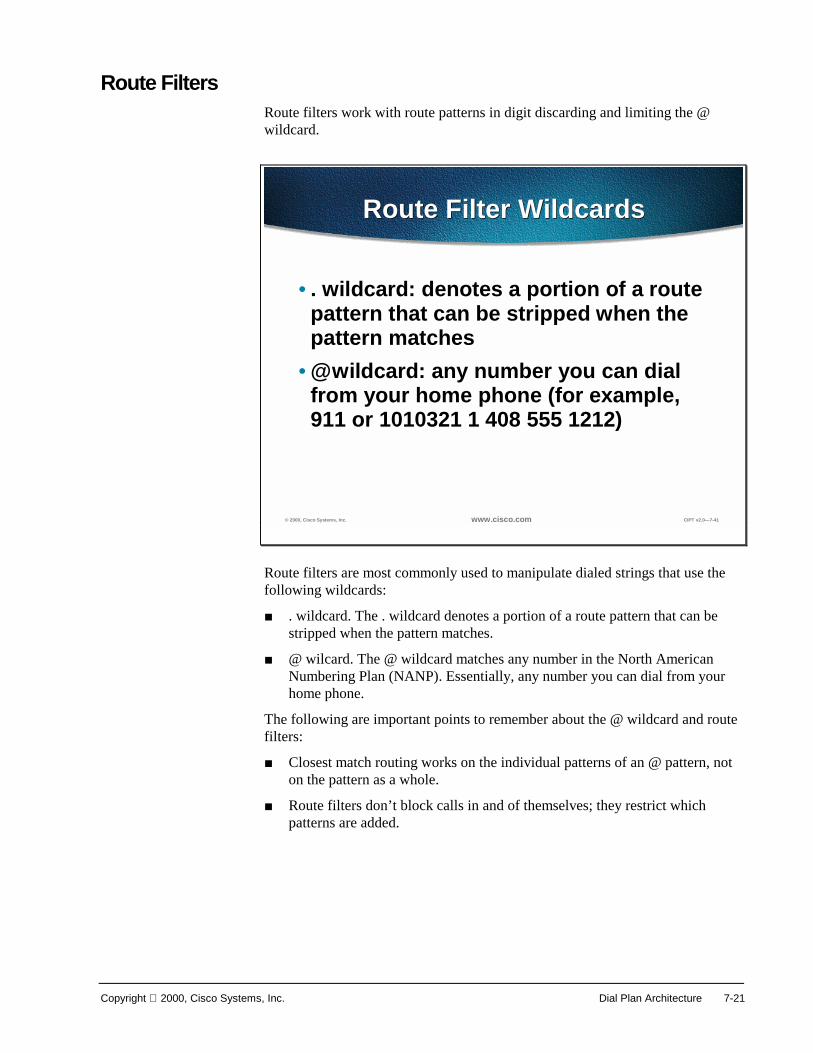
Copyright 2000, Cisco Systems, Inc. Dial Plan Architecture 7-21
Route Filters Route filters work with route patterns in digit discarding and limiting the @ wildcard.
© 2000, Cisco Systems, Inc. www.cisco.com CIPT v2.0—7-41
Route Filter WildcardsRoute Filter Wildcards
• . wildcard: denotes a portion of a route pattern that can be stripped when the pattern matches
• @ wildcard: any number you can dial from your home phone (for example, 911 or 1010321 1 408 555 1212)
Route filters are most commonly used to manipulate dialed strings that use the following wildcards:
■ . wildcard. The . wildcard denotes a portion of a route pattern that can be stripped when the pattern matches.
■ @ wilcard. The @ wildcard matches any number in the North American Numbering Plan (NANP). Essentially, any number you can dial from your home phone.
The following are important points to remember about the @ wildcard and route filters:
■ Closest match routing works on the individual patterns of an @ pattern, not on the pattern as a whole.
■ Route filters don’t block calls in and of themselves; they restrict which patterns are added.
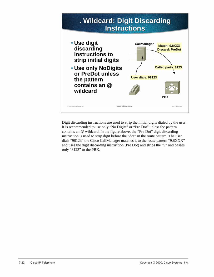
7-22 Cisco IP Telephony Copyright 2000, Cisco Systems, Inc.
© 2000, Cisco Systems, Inc. www.cisco.com CIPT v2.0—7-42
. Wildcard: Digit Discarding Instructions
. Wildcard: Digit Discarding Instructions
• Use digit discarding instructions to strip initial digits
• Use only NoDigits or PreDot unless the pattern contains an @ wildcard
PBX
CallManager Match: 9.8XXXDiscard: PreDot
User dials: 98123
Called party: 8123
Digit discarding instructions are used to strip the initial digits dialed by the user. It is recommended to use only “No Digits” or “Pre Dot” unless the pattern contains an @ wildcard. In the figure above, the “Pre Dot” digit discarding instruction is used to strip digit before the “dot” in the route pattern. The user dials “98123” the Cisco CallManager matches it to the route pattern “9.8XXX” and uses the digit discarding instruction (Pre Dot) and strips the “9” and passes only “8123” to the PBX.

Copyright 2000, Cisco Systems, Inc. Dial Plan Architecture 7-23
© 2000, Cisco Systems, Inc. www.cisco.com CIPT v2.0—7-43
@ Wildcard: Digit Discarding Instructions
@ Wildcard: Digit Discarding Instructions
• Use digit discarding instructions to discard whole sections of the dialed number
• All digit discarding instructions are available
Match: 9.@Discard:
PreDot 10-10-Dialing
User dials: 9101028812145551212
Called party: 12145551212
CallManager
PSTN
The @ wildcard is a macro that causes the CallManager to add about 300 patterns. Use digit discarding instructions to control which digits are sent as the called number and use route filters to add fewer patterns and restrict outside dialing.
The example above shows digit discarding instructions related to the @ wildcard. The user dials “9101028812145551212” and the Cisco CallManager matches the dialed digits to the 9.@ route pattern. The digit discard instructions are to discard a whole section of dialed numbers and in this example the discard instructions are “pre dot” and digits “10-10-Dialing”. The dialed digits from the user are “12145551212” get passed on to the router then to the PSTN.

7-24 Cisco IP Telephony Copyright 2000, Cisco Systems, Inc.
© 2000, Cisco Systems, Inc. www.cisco.com CIPT v2.0—7-44
Digit Discarding InstructionsDigit Discarding Instructions
Used forDiscarded DigitsInstructions
Trailing-#
10-10-Dialing
IntlTollBypass
11D→→→→10D
11D/10D→→→→7DPreAt
PreDot
PSTN compatibility98 1010321 011 33 1234 #
Suppressing carrier selection
98 1010321 1 214 555 1212
Toll bypass98 1010321 011 33 1234 #
Toll bypass98 1010321 1 214 555 1212
Toll bypass98 1010321 1 214 555 1212Access codes98 1 214 555 1212
Access codes98 1 214 555 1212
If the pattern is 9.8@…
If the route pattern is 9.8@ the table above describes the digit discarding instructions that can be applied to the pattern.

Copyright 2000, Cisco Systems, Inc. Dial Plan Architecture 7-25
© 2000, Cisco Systems, Inc. www.cisco.com CIPT v2.0—7-45
Limiting The @ WildcardLimiting The @ Wildcard
• Eliminates or constrains route patterns added by the @ pattern
• Relies on tags, named substrings of the NANP
• Uses three operators: Exists, Does not exist, == <value>
• Operators connected with AND and OR
Because the @ wildcard creates close to 300 route patterns, route filters are used to limit the @ wildcard. The route filters created to limit the @ wildcard rely on tags and named sub-strings of the NANP. Route filters use the following three operators and are connected with “and” and “or”:
■ Exists
■ Does not exist
■ ==<value>
The following four pages show examples using the three operators in a route filter to limit the @ wildcard.

7-26 Cisco IP Telephony Copyright 2000, Cisco Systems, Inc.
© 2000, Cisco Systems, Inc. www.cisco.com CIPT v2.0—7-46
9.@ Route Pattern with no Route Filters
9.@ Route Pattern with no Route Filters
9 [2-9]11
9 [2-9]XXXXXX
9 [2-9]XX[2-9]XX XXXX
9 011 3[0-469]!
The following individual patterns to get added…
9 1 [2-9]XX[2-9]XX XXXX
311, 611, 911 SERVICEs
7-digit dialing by OFFICE CODE
10-digit local dialing byLOCAL AREA CODE
11-digit long distance dialing byAREA CODE
International dialing by COUNTRY CODE
If a route pattern of 9.@ is added with no filters, over three hundred dial strings are possible matches. The following pages show how to limit this route pattern using the following operators:
■ Exist
■ Does not exist
■ == <value>

Copyright 2000, Cisco Systems, Inc. Dial Plan Architecture 7-27
© 2000, Cisco Systems, Inc. www.cisco.com CIPT v2.0—7-47
9.@ with Router Filter SERVICE EXISTS
9.@ with Router Filter SERVICE EXISTS
9 [2-9]11
9 [2-9]XX XXXX
9 [2-9]XX [2-9]XX XXXX
9 011 3[0-469] !
9 1 [2-9]XX [2-9]XX XXXX
Added: contains SERVICE
Not added: no SERVICE
Not added: no SERVICE
Not added: no SERVICE
Not added: no SERVICE
9 [2-9]XX XXXX
9 [2-9]XX [2-9]XX XXXX
9 1 [2-9]XX [2-9]XX XXXX
9 011 3[0-469] !
When the route pattern 9.@ is used with a route filter of “service exist” then only the “9[2-9]11” pattern is added.

7-28 Cisco IP Telephony Copyright 2000, Cisco Systems, Inc.
© 2000, Cisco Systems, Inc. www.cisco.com CIPT v2.0—7-48
9.@ with Route Filter COUNTRY-CODE DOES-NOT-EXIST
9.@ with Route Filter COUNTRY-CODE DOES-NOT-EXIST
9 [2-9]11
9 [2-9]XX XXXX
9 [2-9]XX [2-9]XX XXXX
9 011 3[0-469] !
9 1 [2-9]XX [2-9]XX XXXX
Added: no COUNTRY-CODE
Added: no COUNTRY-CODE
Added: no COUNTRY-CODE
Added: no COUNTRY-CODE
Not added: contains COUNTRY-CODE9 011 3[0-469] !
The 9.@ pattern with the route filter of “country-code does-not-exist” results in the route pattern that contains a country code to be eliminated from the route pattern. This example would be used to filter calls that use a country code.

Copyright 2000, Cisco Systems, Inc. Dial Plan Architecture 7-29
© 2000, Cisco Systems, Inc. www.cisco.com CIPT v2.0—7-49
9.@ with Route Filter AREA CODE == 900
9.@ with Route Filter AREA CODE == 900
9 [2-9]11
9 [2-9]XX XXXX
9 [2-9]XX [2-9]XX XXXX
9 011 3[0-469] !
9 1 [2-9]XX [2-9]XX XXXX
Not added: no AREA-CODE
Not added: no AREA-CODE
Not added: no AREA-CODE (It contains LOCAL-AREA-CODE)
Added: AREA-CODE constrained to 900
Not added: no AREA-CODE
9 [2-9]XX XXXX
9 [2-9]XX [2-9]XX XXXX
900
9 011 3[0-469] !
9 [2-9]11
The 9.@ route pattern with the route filter of “area code == 900” is used to limit the route pattern to calls that go to the area code “900”.

7-30 Cisco IP Telephony Copyright 2000, Cisco Systems, Inc.
© 2000, Cisco Systems, Inc. www.cisco.com CIPT v2.0—7-50
Tags In The NANP Dial PlanTags In The NANP Dial Plan
The escape sequence used for entering a long distance carrier code101 0321 1 214 555 1212TRANSIT-NETWORK-ESCAPE
Long distance carrier code101 0321 1 214 555 1212TRANSIT-NETWORK
A particular extension served by a given exchange1 214 555 1212SUBSCRIBER
Access to local telephony provider services1 411SERVICE
A specific value associated with calls to the satellite country code01 1 881 4 1234 #SATELLITE-SERVICE
The office or exchange code of a North American call1 214 555 1212OFFICE-CODE
The national number component of an international call01 1 33 123456 #NATIONAL-NUMBER
The initial 0 required for operator-assisted long-distance calls0 214 555 1212LONG-DISTANCE-OPERATOR
The initial 1 required for long distance direct-dial calls1 214 555 1212LONG-DISTANCE-DIRECT-DIAL
The initial 0 required for operator-assisted local calls0 555 1212LOCAL-OPERATOR
The initial 1 required by some 7-digit calls1 555 1212LOCAL-DIRECT-DIAL
The area code in a 10-digit local call214 555 1212LOCAL-AREA-CODE
The digit that denotes the operator component of an international call01 0INTERNATIONAL OPERATOR
The digit that denotes the direct-dial component of an international call01 1 33 123456 #INTERNATIONAL-DIRECT-DIAL
The initial 01 of an international call01 1 33 123456 #INTERNATIONAL-ACCESS
The #, which cancels inter-digit timeout in international calls01 1 33 123456 #END-OF-DIALING
The country code in an international call01 1 33 123456 #COUNTRY-CODE
The area code in an 11-digit long distance call1 214 555 1212AREA-CODE
DescriptionExample numberTag Name
The @ wildcard can be used to easily establish matches in route patterns to over 300 dial strings. The table above represents the tags use in the NANP Dial Plan that will help in creating route filters for a route pattern with an @ wildcard.
Digit Translation Tables The capability exists within CallManager to provide for digit translation. This is the ability of “translating” a dialed number into another number or even changing the number of digits. This can be achieved for internal as well as external calls whether inbound or outbound. Translation Table may be configured such that when a user dials a zero then the call gets delivered to an attendant who may have an extension that is 1111.

Copyright 2000, Cisco Systems, Inc. Dial Plan Architecture 7-31
? 2000, Cisco Systems, Inc. www.cisco.com CIPT v2.0? -17
Digit Translation TableDigit Translation Table
DID Range1000-1999
DID Range1000-1999
Attendant? 111�
Translation Table Translation Mask11111XXX
No Match of DNNo Match of DN
Match DNMatch DN
The following is an example of a common application of a translation table. Many customers desire that unassigned DID (Direct Inward Dial) numbers get sent to an attendant if those numbers are dialed.
Lets say a customer has a DID range from 1000-1999 and they want all calls to unassigned DID numbers to go to an attendant at extension 1111. In this case a Translation Table of 1XXX would be configured that pointed to a translation mask of 1111.
Wildcards are used in the above example. CallManager performs a longest match lookup up where if an IP phone exists in the 1000-1999 range, it will send the call to the IP phone. If no IP phone exists in the 1000-1999 range then the match will occur on the 1XXX translation table and the call will be sent to extension 1111.

7-32 Cisco IP Telephony Copyright 2000, Cisco Systems, Inc.
© 2000, Cisco Systems, Inc. www.cisco.com CIPT v2.0—7-52
Translation PatternsTranslation Patterns
• Almost exactly like route pattern: uses wildcards, transformations, etc.
• Results of transformations are the input for another trip through digit analysis
• Use to handle extension mapping
Translation patterns are almost exactly like route patterns in its use of wildcards and transformations. The digit collection in a translation pattern results in another trip through digit analysis. The primary use of translation patterns is for extension mapping.

Copyright 2000, Cisco Systems, Inc. Dial Plan Architecture 7-33
© 2000, Cisco Systems, Inc. www.cisco.com CIPT v2.0—7-53
Routing Flowchart
Pattern type?
Find best matchDigits
Apply calling and calledparty transformations
Extend call to destination
Route pattern
DigitsFind best match
Apply calling and calledparty transformations
Pattern type? Translation pattern
The above routing flow chart shows at what point the digits go back through digit analysis when using a translation pattern. In the routing flowchart, the digit analysis determines what pattern type is being used. When a translation pattern is used, the digits go back through digit analysis. When a route pattern is used, the call is extended to the destination.

7-34 Cisco IP Telephony Copyright 2000, Cisco Systems, Inc.
© 2000, Cisco Systems, Inc. www.cisco.com CIPT v2.0—7-56
Translation PatternsTranslation Patterns
• The calling search space parameter on translation patterns provides a mechanism to handle overlapped dial plans such as would be common in a multiple tenant situation
• Calling search space and partitions are covered in the next section
Translation patterns are very useful in a multi-tenant situation. The calling search space parameter (that is discussed later in this chapter) used on translation patterns provide a mechanism to handle overlapped dial plans.

Copyright 2000, Cisco Systems, Inc. Dial Plan Architecture 7-35
Special Dial String Considerations A goal of the dial plan is to be as simple as possible and to minimize the number of entries. The most efficient way to achieve this is to configure specific dial plans only for On-Net (IP WAN) locations and to use the local PSTN gateway access code (such as 9 or 0) for Off-Net calls that must take the PSTN as well as act as an alternate path for IP WAN calls if the IP WAN is down or has insufficient resources.
“On-Net” Route Pattern This assumes the multi-site IP WAN with a distributed call processing model typically where an abbreviation of the full E.164 address will be is used for ease of dialing for the user in this case. Take the case of where an On-Net location has a number range of (408) 526-1000 through 1999. In this case there may only be a single route pattern that will have an entry of “61XXX”. This simplifies user dialing and requires only one route pattern entry where the Xs serve as Wildcards.
The CallManager route pattern can also strip/pre-pend digits to the dial number in order to present the remote CallManager with the appropriate internal dial plan length. In fact for all IP WAN calls the number of digits presented to a remote CallManager across the IP WAN must also match the dialed digit length that the remote site uses for internal calls. The remote CallManager will simply look at the digits and route the call. There is no digit manipulation for incoming calls.
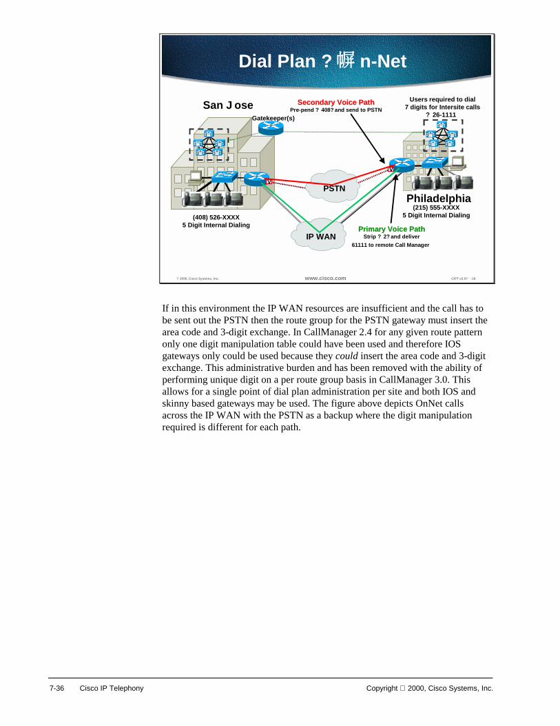
7-36 Cisco IP Telephony Copyright 2000, Cisco Systems, Inc.
? 2000, Cisco Systems, Inc. www.cisco.com CIPT v2.0? -18
PSTN
IP WAN
A
A
V
V
Gatekeeper(s)
Primary Voice PathPrimary Voice PathStrip ? 2? and deliver
61111 to remote Call Manager
Secondary Voice PathSecondary Voice PathPre-pend ? 408? and send to PSTN
(408) 526-XXXX5 Digit Internal Dialing
Users required to dial7 digits for Intersite calls
? 26-1111�
Dial Plan ? n-Net�
San Jose
Philadelphia(215) 555-XXXX
5 Digit Internal Dialing
If in this environment the IP WAN resources are insufficient and the call has to be sent out the PSTN then the route group for the PSTN gateway must insert the area code and 3-digit exchange. In CallManager 2.4 for any given route pattern only one digit manipulation table could have been used and therefore IOS gateways only could be used because they could insert the area code and 3-digit exchange. This administrative burden and has been removed with the ability of performing unique digit on a per route group basis in CallManager 3.0. This allows for a single point of dial plan administration per site and both IOS and skinny based gateways may be used. The figure above depicts OnNet calls across the IP WAN with the PSTN as a backup where the digit manipulation required is different for each path.

Copyright 2000, Cisco Systems, Inc. Dial Plan Architecture 7-37
All Calls out of the PSTN For all calls out of the PSTN this typically will only require a single route pattern that will be the PSTN trunk access code, which is usually a 9 or a 0. In North America the route pattern 9.@ can be configured such that all users making outside calls will dial a 9 (9 is most commonly used) and simply dial the telephone 7 or 1+ 10-digit phone number. In CallManager 3.0 Local Area Codes do not exist and therefore should be configured specifically and not require a 1. This way CallManager can differentiate between a local 7-digit numbers vs. a local area code in order to determine when the dialing is complete. Otherwise the CallManager will wait 10 seconds without detecting any digits before assuming the dialing is complete.
? 2000, Cisco Systems, Inc. www.cisco.com CIPT v2.0? -19
Calls out of the PSTNCalls out of the PSTN
• Skinny based and MGCP gateways have alltheir dial plan information done in CallManager
• H.323 based IOS gateway typically onlyrequires a minimal amount of dial peers
As far as local PSTN the gateway dial plan configuration it is fairly simple. The skinny based and MGCP gateways have all their dial plan information done in CallManager while an H.323 based IOS gateway typically only requires a minimal amount of dial peers. These dial peers would be used by the gateway to direct all calls from CallManager to the PSTN. In the dial plan configuration section there will be an example of the IOS H.323 gateway dial peer configuration.

7-38 Cisco IP Telephony Copyright 2000, Cisco Systems, Inc.
? 2000, Cisco Systems, Inc. www.cisco.com CIPT v2.0? -20
Outside North AmericaOutside North America
• Multiple length dial plans presents a challenge• CallManager does not know when dialing is
complete, unless you have a specificroute pattern
• CallManager by default will wait 10 secondswithout receiving any digits before assumingdialing is complete
• Two route pattern options:–Option 1 – 0.!–Option 2 – 0.!#
In areas outside North America it is common to have different countries use different length dial strings. Multiple length dial plans presents a challenge in that the CallManager does not know when dialing is complete unless you have a specific route pattern. CallManager by default will wait ten seconds without receiving any digits before assuming dialing is complete. Below are common options for configuring a route pattern for the PSTN access outside of North America. The local PSTN access code used will be “0” which is commonly used.
Option 1—Route Pattern = 0.! “0.”—Represents the local PSTN access code.
“!”—Stands for any digit and any number of digits. This also means that the CallManager will wait ten seconds by default without receiving any digits before assuming the dialing is complete and then sending the call.
A common option here is reducing the idle digit wait timer in the CallManager service parameters to three seconds. This will allow for a call to be sent sooner when the user is finished dialing instead of having the user wait the annoying ten seconds before the call gets sent. The risk, however, of reducing this is that the CallManager may determine that the dialing is finished prematurely if the user simply pauses.
Option 2—Route Pattern = 0.!# “0.”—Represents the local PSTN access code.
“!”—Stands for any digit and any number of digits. This also means that the CallManager will wait ten seconds without receiving any digits before assuming the dialing is complete.
“#”—This indicates when a user hits the # key CallManager will assume dialing is complete immediately and send the call.

Copyright 2000, Cisco Systems, Inc. Dial Plan Architecture 7-39
In this option users are instructed to dial the # (pound/hash) key to terminate the dial string and immediately place the call. This requires some user education and some changes to existing customer dialing habits, which can be met with varying degrees of resistance. However, this is similar in nature to pressing the Send button on a cell phone.

7-40 Cisco IP Telephony Copyright 2000, Cisco Systems, Inc.
Configuring Dial Plan Groups and Calling Restrictions
New in CallManager 3.0 is the ability of providing calling restrictions on a per phone basis as well as the creation of closed dial plan groups on the same CallManager. Users can be grouped into communities of interest on the same CallManager that have the same calling restrictions as well as dial plans. Different communities of interest can operate as ships in the night from one another, share the same gateways as well as have overlapping dial plans. This ability has a particular interest in the multi-site IP WAN with centralized call processing deployment model. These new capabilities are achieved in CallManager 3.0 with the use of partitions and calling search spaces.
? 2000, Cisco Systems, Inc. www.cisco.com CIPT v2.0? -21
Subnet (Partition) A
Subnet (Partition)B
Subnet (Partition)C
Inbound Access-List(Calling Search Space)
Where you may reachWhere you may reach
Partition/Calling Search Space
Analogous to:
Subnet/Access-List
Understanding Partitions +Calling Search Spaces
Where You Are Where You Are
Partitions and calling search spaces draw an analogy to routers with access lists. Think of a partition as an IP subnet where you will place users. A calling search space is likened to an inbound access list that dictates “which” subnet you can reach.

Copyright 2000, Cisco Systems, Inc. Dial Plan Architecture 7-41
© 2000, Cisco Systems, Inc. www.cisco.com CIPT v2.0—7-25
Partitions And Calling Search Spaces Analogy
Partitions And Calling Search Spaces Analogy
Rita Dave972 813 5000
SWB Dallas Yellow PagesDave 972 813 5000
SWB Dallas White PagesSWB Dallas Yellow Pages
Little Black Book
Rita’s list of directories The directory in which Dave’s number is listed is his number’s partition
The list of directories in which Rita looks up numbers is her calling search space
The analogy above shows the relationship between calling search space and partitions. A partition is a directory where a user list their number and a calling search space are the directories a users is able to look in to make calls.
In the analogy, Dave list his number is the “SWB Dallas Yellow Pages” directory. This is the partition that Dave belongs to.
Rita has a list of directories (SWB Dallas White Pages, SWB Dallas Yellow Pages and her Little Black Book) that represent her calling search space.
If Rita does not have a directory that Dave is in (SWB Dallas Yellow Pages), then she is unable to call Dave. In other words, if Rita is assigned to a Calling Search Space that does not include the partition that Dave is in, then Rita cannot call Dave.
If Rita does have a directory that Dave is in (SWB Dallas Yellow Pages), then she is able to call Dave. In other words, if Rita is assigned to a Calling search space that includes the partition that Dave is in, then Rita is able to call Dave.

7-42 Cisco IP Telephony Copyright 2000, Cisco Systems, Inc.
© 2000, Cisco Systems, Inc. www.cisco.com CIPT v2.0—7-63
Partitions And Calling Search Spaces Definition
Partitions And Calling Search Spaces Definition
• Partition: A logical grouping of patterns. All patterns in a partition are equally reachable
• Calling search space: An ordered list of partitions. Digit analysis looks through the caller’s list of partitions when searching for the closest match for the caller’s dialed number
Partitions Partitions are considered to be a group of devices with similar reachability characteristics. Devices that get placed in partitions are IP phones, DNs and route patterns. These are entities associated with DNs (directory numbers) that users will dial to reach. Partition names should be chosen to have some meaningful correlation to the group of users it represents. For example, for users located in Building D in San Jose you may want to create a partition called SJD.
Calling Search Space A calling search space is an ordered list of partitions that a user may look in before being allowed to place a call. Calling search spaces are assigned to devices that may initiate calls. These include IP phones, soft phones and gateways.
The way dialing restrictions can be invoked is simple in that when a user is assigned a calling search space, the list of partitions in the calling search space only are ones that the caller is allowed to reach. DNs dialed that fall in a partition not in a caller’s calling search space will be given a busy signal.

Copyright 2000, Cisco Systems, Inc. Dial Plan Architecture 7-43
© 2000, Cisco Systems, Inc. www.cisco.com CIPT v2.0—7-64
Partitions And Calling Search Spaces Rules
Partitions And Calling Search Spaces Rules
• Digit analysis looks through every partition in a calling search space and looks for the best match
• Order of partitions listed in the calling search space is used only to break ties when there are equally good matches in two different partitions.
• If no partition is specified for a pattern, the pattern is listed in the null partition.
Partitions and calling search spaces follow rules when doing digit analysis. Digit analysis will look through every partition inn a calling search space and looks for the best match. The order of the partitions listed in the calling search space is used only to break ties when there are equally good matches in two different partitions. If no partition is specified for a pattern, the pattern is listed in the null partition (as well as any partitions specified in their calling search space) to resolve dialed digits. The null partition is always the last partition looked through.

7-44 Cisco IP Telephony Copyright 2000, Cisco Systems, Inc.
? 2000, Cisco Systems, Inc. www.cisco.com CIPT v2.0? -22
PSTN
EmployeePhones
Partition AssignmentPartition AssignmentJ-Users? = All SJ IP PhonesJ-PSTN? = ? ? Route Pattern
Calling Search SpaceCalling Search Spacenrestricted? = SJ-Users, SJ-PSTNJ-Only? = SJ-Users
IP Phone Calling Search Space AssignmentStaff IP Phones = nrestricted?
Lobby IP Phones = J-Only?
A
V
LobbyPhones
Employees ay dial anywhere
Lobby phones nly can dial internal to SJ
San Jose
Example of Calling Search Spaceand Partition
The figure above illustrates a basic example of how partitions and calling search spaces may be used to provide dialing restrictions.
In this example staff employees have unrestricted dialing where as the lobby phones only have the ability of dialing people within the local site. As noted in the diagram all IP phones are placed in the SJ-Users partition and the route pattern 9 associated with the PSTN is placed in the SJ-PSTN partition. Two calling search spaces are created that denote two different dialing characteristics. A calling search space called unrestricted is created that has both SJ-Users and SJ-PSTN Partitions in it. A second calling search space called SJ-Only is created with only the SJ-Users in it. San Jose staff IP phones are assigned the unrestricted calling search space denoting that they may dial anywhere. The lobby phones are assigned the SJ-Only calling search space meaning they can only dial local phones in the building.
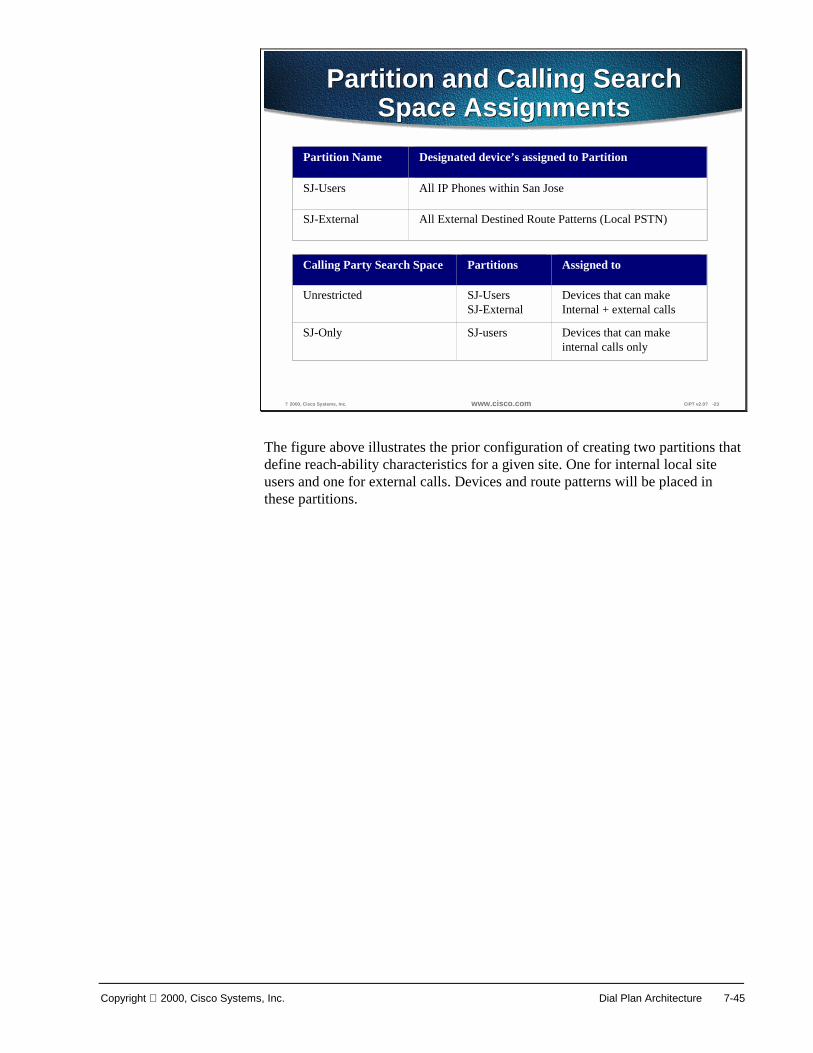
Copyright 2000, Cisco Systems, Inc. Dial Plan Architecture 7-45
? 2000, Cisco Systems, Inc. www.cisco.com CIPT v2.0? -23
Partition and Calling SearchSpace Assignments
Partition and Calling SearchSpace Assignments
Calling Party Search Space Partitions Assigned to
Unrestricted SJ-UsersSJ-External
Devices that can makeInternal + external calls
SJ-Only SJ-users Devices that can makeinternal calls only
Partition Name Designated device’s assigned to Partition
SJ-Users All IP Phones within San Jose
SJ-External All External Destined Route Patterns (Local PSTN)
The figure above illustrates the prior configuration of creating two partitions that define reach-ability characteristics for a given site. One for internal local site users and one for external calls. Devices and route patterns will be placed in these partitions.
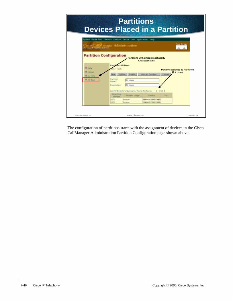
7-46 Cisco IP Telephony Copyright 2000, Cisco Systems, Inc.
? 2000, Cisco Systems, Inc. www.cisco.com CIPT v2.0? -24
PartitionsDevices Placed in a Partition
Devices assigned to PartitionsJ Users�
Partitions with unique reachabilityCharacteristics
The configuration of partitions starts with the assignment of devices in the Cisco CallManager Administration Partition Configuration page shown above.
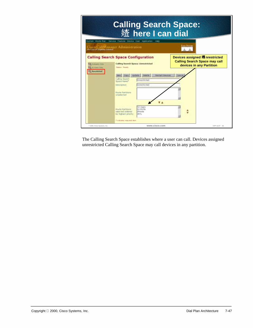
Copyright 2000, Cisco Systems, Inc. Dial Plan Architecture 7-47
? 2000, Cisco Systems, Inc. www.cisco.com CIPT v2.0? -25
Calling Search Space:here I can dial�
Devices assigned nrestricted�
Calling Search Space may calldevices in any Partition
The Calling Search Space establishes where a user can call. Devices assigned unrestricted Calling Search Space may call devices in any partition.

7-48 Cisco IP Telephony Copyright 2000, Cisco Systems, Inc.
? 2000, Cisco Systems, Inc. www.cisco.com CIPT v2.0? -26
Assigning Partitions and Calling SearchSpaces lobal Phone Configuration Level�
alling Search Space�
can be assigned to IP phone
Only alling Search Space? configured at main phone configuration
You will need to assign partitions and calling search spaces at the global Phone Configuration level. At the main Phone Configuration page, only the Calling Search Space is configured as shown in the example above.
The default setting for Calling Search Space allows a user to call anyone, but if other devices do not have a Calling Search Space of default, no one can call devices in the default group.
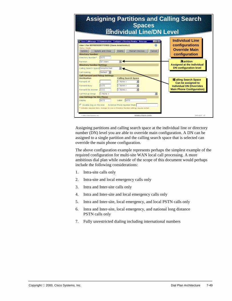
Copyright 2000, Cisco Systems, Inc. Dial Plan Architecture 7-49
? 2000, Cisco Systems, Inc. www.cisco.com CIPT v2.0? -27
alling Search Space�
Can be assigned toIndividual DN (Overrides
Main Phone Configuration)
alling Search Space�
Can be assigned toIndividual DN (Overrides
Main Phone Configuration)
Individual LineconfigurationsOverride Mainconfiguration
Individual LineconfigurationsOverride Mainconfiguration
Assigning Partitions and Calling SearchSpaces
ndividual Line/DN Level�
artition�
Assigned at the IndividualDN configuration level
artition�
Assigned at the IndividualDN configuration level
Assigning partitions and calling search space at the individual line or directory number (DN) level you are able to override main configuration. A DN can be assigned to a single partition and the calling search space that is selected can override the main phone configuration.
The above configuration example represents perhaps the simplest example of the required configuration for multi-site WAN local call processing. A more ambitious dial plan while outside of the scope of this document would perhaps include the following considerations:
1. Intra-site calls only
2. Intra-site and local emergency calls only
3. Intra and Inter-site calls only
4. Intra and Inter-site and local emergency calls only
5. Intra and Inter-site, local emergency, and local PSTN calls only
6. Intra and Inter-site, local emergency, and national long distance PSTN calls only
7. Fully unrestricted dialing including international numbers
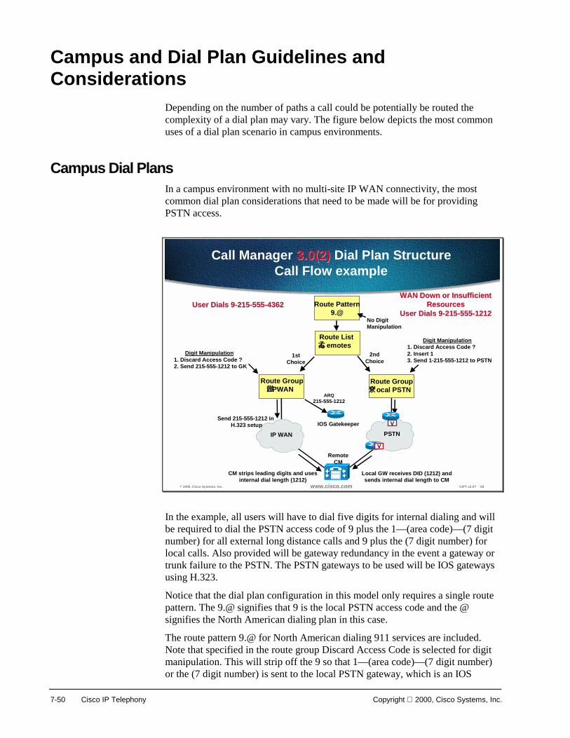
7-50 Cisco IP Telephony Copyright 2000, Cisco Systems, Inc.
Campus and Dial Plan Guidelines and Considerations
Depending on the number of paths a call could be potentially be routed the complexity of a dial plan may vary. The figure below depicts the most common uses of a dial plan scenario in campus environments.
Campus Dial Plans In a campus environment with no multi-site IP WAN connectivity, the most common dial plan considerations that need to be made will be for providing PSTN access.
? 2000, Cisco Systems, Inc. www.cisco.com CIPT v2.0? -28
Route Pattern9.@
Route Listemotes�
Route GroupPWAN�
1stChoice
2ndChoice
PSTNIP WAN
Route Groupocal PSTN�
Digit Manipulation1. Discard Access Code ? �2. Send 215-555-1212 to GK
No Digit Manipulation
V
Call Manager 3.0(2)3.0(2) Dial Plan StructureCall Flow example
IOS Gatekeeper
ARQ215-555-1212
Send 215-555-1212 in H.323 setup
CM strips leading digits and usesinternal dial length (1212)
Digit Manipulation1. Discard Access Code ? �2. Insert 13. Send 1-215-555-1212 to PSTN
V
Local GW receives DID (1212) andsends internal dial length to CM
RemoteCM
User Dials 9-215-555-4362User Dials 9-215-555-4362WAN Down or InsufficientWAN Down or Insufficient
ResourcesResourcesUser Dials 9-215-555-1212User Dials 9-215-555-1212
In the example, all users will have to dial five digits for internal dialing and will be required to dial the PSTN access code of 9 plus the 1—(area code)—(7 digit number) for all external long distance calls and 9 plus the (7 digit number) for local calls. Also provided will be gateway redundancy in the event a gateway or trunk failure to the PSTN. The PSTN gateways to be used will be IOS gateways using H.323.
Notice that the dial plan configuration in this model only requires a single route pattern. The 9.@ signifies that 9 is the local PSTN access code and the @ signifies the North American dialing plan in this case.
The route pattern 9.@ for North American dialing 911 services are included. Note that specified in the route group Discard Access Code is selected for digit manipulation. This will strip off the 9 so that 1—(area code)—(7 digit number) or the (7 digit number) is sent to the local PSTN gateway, which is an IOS

Copyright 2000, Cisco Systems, Inc. Dial Plan Architecture 7-51
gateway in this case. The CallManager denotes any digits to the left of the “.” as the access code so when Discard Access Code is selected it will strip off any digits to the left of the “.”. Note that in the route group two gateways are listed in order of preference. This is how gateway redundancy will be achieved in the event of an all trunks busy condition or a gateway failure.

7-52 Cisco IP Telephony Copyright 2000, Cisco Systems, Inc.
? 2000, Cisco Systems, Inc. www.cisco.com CIPT v2.0? -29
dial-peer voice 1 voip codec g711ulaw dtmf-relay h245-alphanumeric destination-pattern 6.... session target ipv4:10.1.10.5!dial-peer voice 2 pots destination-pattern ? . port 1/0:1!dial-peer voice 3 pots destination-pattern 1? ? prefix 1 port 1/0:1!dial-peer voice 4 pots destination-pattern 911 prefix 911 port 1/0:1
Dial-Peer for all incoming callsfrom PSTN to Call
Manager IP Address
Must be G.711
Dial Peer for all 7 digit outgoingPSTN Numbers
Dial Peer for all 10 digit outgoingPSTN Numbers
Dial Peer for 911 Services
Call Manager IP Address
For Incoming CallsAssuming DID
(Direct Inward Dial)
For Outgoing Calls
Note - For ON DID? Incoming Calls (Analog trunks)Note - For ON DID? Incoming Calls (Analog trunks)1. Dedicate each incoming trunk to user with onnection PLAR�
or2. Send all calls to an Attendant
Local PSTN GW Configuration
Global ConfigurationMode
Above is the configuration required in each IOS PSTN gateway. The goal is to be able to configure the IOS H.323 gateway with a minimum amount of entries as possible. The ideal situation is that all the dial plan configuration would occur in CallManager. This is the case with skinny + MGCP based gateways. However the more prominent gateways available are H.323 based so they are used in the following example:
The above configuration would assume that 1 + 10 digit dialing would be required for long distance calls to the PSTN and where 7 digit dialing would be required for local PSTN calling.
Note that within the scope of 9.@ that emergency 911 services are included. That means a user dialing 911 will get sent out the PSTN trunks automatically however the IOS H.323 gateway still requires a dial peer for 911 as depicted. Various dial peers can be added for 411 + 611 services, which are included in the scope of the 9.@ route pattern as well.

Copyright 2000, Cisco Systems, Inc. Dial Plan Architecture 7-53
Summary This section summarizes the concepts you learned in this chapter.
? 2000, Cisco Systems, Inc. www.cisco.com CIPT v2.0? -30
SummarySummary
• The dial plan architecture is designed tohandle internal and external calls.
• Partitions and calling search spaces areanalogous to routers with access lists.
• Cisco CallManager provides digittranslation.
The CallManager’s dial plan architecture is setup to handle generally two types of calls:
■ Internal calls to IP phones registered to the CallManager cluster itself
■ External calls via a PSTN gateway or to another CallManager cluster via the IP WAN
Partitions and calling search spaces draw an analogy to routers with access lists. Think of a partition as an IP subnet where you will place users. A calling search space is likened to an inbound access list that dictates which subnet you can reach.
The capability exists within CallManager to provide for digit translation. This is the ability of translating a dialed number into another number or even changing the number of digits. This can be achieved for internal as well as external calls whether inbound or outbound. Translation table may be configured such that when a user dials a 0 then call gets delivered to an attendant who may have an extension that is 1111.

7-54 Cisco IP Telephony Copyright 2000, Cisco Systems, Inc.
Review Questions Answer the following questions.
? 2000, Cisco Systems, Inc. www.cisco.com CIPT v2.0? -31
Review QuestionsReview Questions
1. In a CIPT solution what is an example ofalternate path routing?
2. What is the recommended order forconfiguring a route pattern?
3. How are partitions and calling search spacesrelated?
Q1) The Cisco IP telephony solution takes full advantage of an IP network. What is an example of alternate path call routing in a CIPT solution?
Q2) Route groups, devices, route pattern and route list are parts that need to be configured for a route pattern. What is the recommended order for configuring a route pattern?
Q3) Partitions and calling search spaces provide calling restrictions on a per phone basis as well as the creation of closed dial plan groups on the same CallManager. What is the relationship between partitions and calling search spaces?

8
Overview The Cisco AVVID telephony solution offers multiple methods of connecting an IP telephony network to the PSTN, legacy PBX, and key systems. Choosing a gateway form a list of twenty products can be daunting when first attempted. Cisco’s product line ranges from specialized, entry-level stand-alone voice gateways to the high-end, feature rich Integrated Router and Catalyst gateways. However, once a list of required features is combined with the long-term needs of the product, a gateway solution can be found.
This chapter discusses the Cisco access gateways that are in the CIPT environment and includes the following topics:
■ Objectives
■ Gateway Requirements
■ Single-Site Enterprise Deployments
■ Install and Configure Commands
■ Laboratory Exercise
■ Summary
■ Review Questions
8-2 Cisco IP Telephony Copyright 2000, Cisco Systems, Inc.
Objectives This section lists the chapter objectives.
? 2000, Cisco Systems, Inc. www.cisco.com CIPT v2.0? -3
ObjectivesObjectives
Upon completion of this chapter, you willbe able to perform the following tasks:• Identify the criteria needed to select a gateway• Identify and describe the hardware
components of the Cisco access gateways• Add and Configure the selected Cisco access
gateway
Upon completion of this chapter, you will be able to complete the following tasks:
■ Given a case study of existing networking and telephony components, identify the criteria needed to select a gateway.
■ Given a Cisco access gateway, identify and describe the hardware components of the Cisco access gateways.
■ Given a Cisco access gateway and network topology, add and configure the selected Cisco access gateway to the CIPT network.

Copyright 2000, Cisco Systems, Inc. Cisco Access Gateways 8-3
Gateway Requirements This section describes the gateway requirements. Different gateway protocols are supported with Cisco CallManager. The tables below show which gateways support a given protocol.
? 2000, Cisco Systems, Inc. www.cisco.com CIPT v2.0? -4
Gateway Protocol MatrixGateway Protocol Matrix
Gateway MGCP H.323 Skinny Station Protocol
VG200 Yes Phase 2 No
DT-24+/DE-30+ No No Yes
Catalyst 4000 WS-X4604-
GWY Gateway Module
Future Yes, for PSTN Interfaces
Yes, for Conferencing and
MTP/ Transconding
Services Catalyst 6000 WS-X6608-x1
Gateway Module
Future No Yes
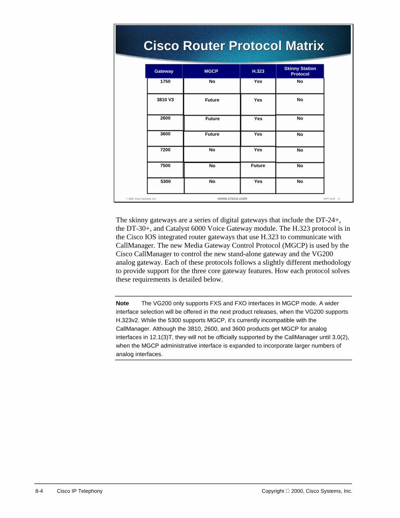
8-4 Cisco IP Telephony Copyright 2000, Cisco Systems, Inc.
? 2000, Cisco Systems, Inc. www.cisco.com CIPT v2.0? -5
Cisco Router Protocol MatrixCisco Router Protocol Matrix
5300 No Yes No
1750 No Yes No
3810 V3 Future Yes No
2600 Future Yes No
3600 Future Yes No
7200 No Yes No
7500 No Future No
Gateway MGCP H.323 Skinny StationProtocol
The skinny gateways are a series of digital gateways that include the DT-24+, the DT-30+, and Catalyst 6000 Voice Gateway module. The H.323 protocol is in the Cisco IOS integrated router gateways that use H.323 to communicate with CallManager. The new Media Gateway Control Protocol (MGCP) is used by the Cisco CallManager to control the new stand-alone gateway and the VG200 analog gateway. Each of these protocols follows a slightly different methodology to provide support for the three core gateway features. How each protocol solves these requirements is detailed below.
Note The VG200 only supports FXS and FXO interfaces in MGCP mode. A wider interface selection will be offered in the next product releases, when the VG200 supports H.323v2. While the 5300 supports MGCP, it’s currently incompatible with the CallManager. Although the 3810, 2600, and 3600 products get MGCP for analog interfaces in 12.1(3)T, they will not be officially supported by the CallManager until 3.0(2), when the MGCP administrative interface is expanded to incorporate larger numbers of analog interfaces.
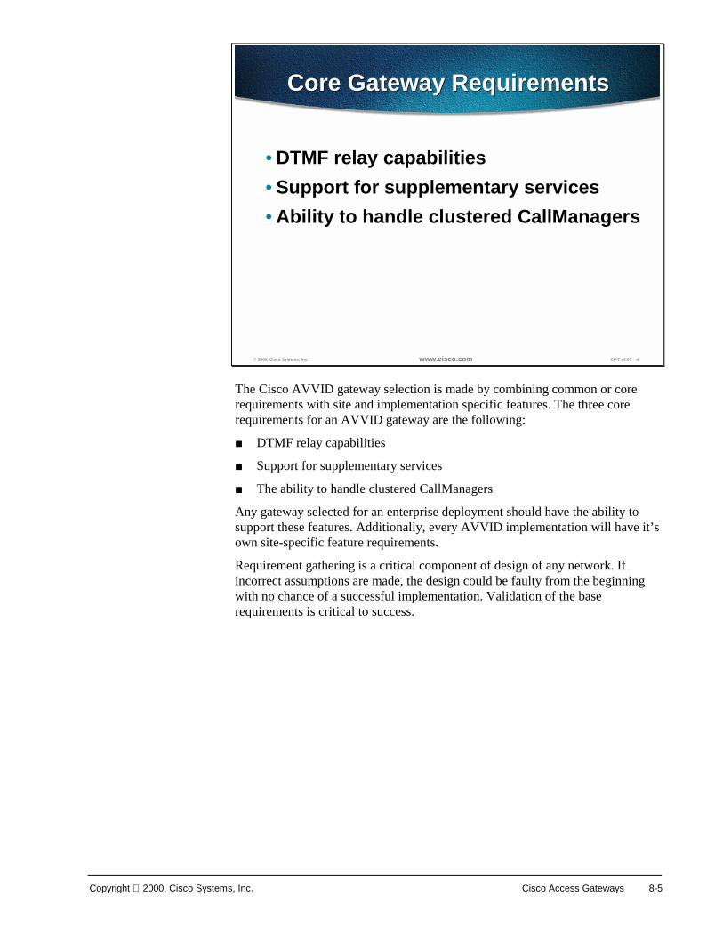
Copyright 2000, Cisco Systems, Inc. Cisco Access Gateways 8-5
? 2000, Cisco Systems, Inc. www.cisco.com CIPT v2.0? -6
Core Gateway RequirementsCore Gateway Requirements
• DTMF relay capabilities• Support for supplementary services• Ability to handle clustered CallManagers
The Cisco AVVID gateway selection is made by combining common or core requirements with site and implementation specific features. The three core requirements for an AVVID gateway are the following:
■ DTMF relay capabilities
■ Support for supplementary services
■ The ability to handle clustered CallManagers
Any gateway selected for an enterprise deployment should have the ability to support these features. Additionally, every AVVID implementation will have it’s own site-specific feature requirements.
Requirement gathering is a critical component of design of any network. If incorrect assumptions are made, the design could be faulty from the beginning with no chance of a successful implementation. Validation of the base requirements is critical to success.

8-6 Cisco IP Telephony Copyright 2000, Cisco Systems, Inc.
DTMF Relay
? 2000, Cisco Systems, Inc. www.cisco.com CIPT v2.0? -7
DTMF RelayDTMF Relay
• Signaling method that uses specific pairs offrequencies within the voiceband for signals
• Signals carried without difficulty over a 64kbpsPCM voice channel
• DTMF signal loss or distortion when using alow bite-rate codec for voice compression
• Provide an out-of-band signaling method forcarrying DTMF tones across a Voice over IPinfrastructure
Dual-Tone Multifrequency (DTMF) is a signaling method that uses specific pairs of frequencies within the voiceband for signals. The signal in this case is the digits. In voice, signal means on-hook, off-hook, and so forth. The actual representation of the two frequencies is a number or digit. Over a 64kbps PCM voice channel, these signals can be carried without difficulty. However, when using a low bite-rate codec for voice compression, the potential exist for DTMF signal loss or distortion. An elegant solution for these codec induced symptoms is providing an out-of-band signaling method for carrying DTMF tones across a Voice over IP infrastructure.
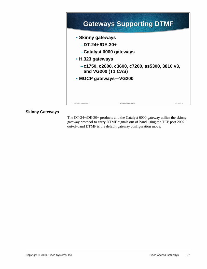
Copyright 2000, Cisco Systems, Inc. Cisco Access Gateways 8-7
? 2000, Cisco Systems, Inc. www.cisco.com CIPT v2.0? -8
Gateways Supporting DTMFGateways Supporting DTMF
• Skinny gateways–DT-24+/DE-30+–Catalyst 6000 gateways
• H.323 gateways–c1750, c2600, c3600, c7200, as5300, 3810 v3,
and VG200 (T1 CAS)• MGCP gateways—VG200
Skinny Gateways The DT-24+/DE-30+ products and the Catalyst 6000 gateway utilize the skinny gateway protocol to carry DTMF signals out-of-band using the TCP port 2002. out-of-band DTMF is the default gateway configuration mode.
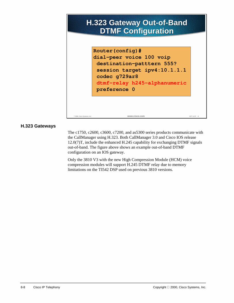
8-8 Cisco IP Telephony Copyright 2000, Cisco Systems, Inc.
? 2000, Cisco Systems, Inc. www.cisco.com CIPT v2.0? -9
H.323 Gateway Out-of-BandDTMF Configuration
H.323 Gateway Out-of-BandDTMF Configuration
Router(config)#dial-peer voice 100 voipdestination-patttern 555?session target ipv4:10.1.1.1codec g729ar8dtmf-relay h245-alphanumericpreference 0
H.323 Gateways The c1750, c2600, c3600, c7200, and as5300 series products communicate with the CallManager using H.323. Both CallManager 3.0 and Cisco IOS release 12.0(7)T, include the enhanced H.245 capability for exchanging DTMF signals out-of-band. The figure above shows an example out-of-band DTMF configuration on an IOS gateway.
Only the 3810 V3 with the new High Compression Module (HCM) voice compression modules will support H.245 DTMF relay due to memory limitations on the TI542 DSP used on previous 3810 versions.

Copyright 2000, Cisco Systems, Inc. Cisco Access Gateways 8-9
? 2000, Cisco Systems, Inc. www.cisco.com CIPT v2.0? -10
MGCP DTMF RelayConfiguration
MGCP DTMF RelayConfiguration
Router(config)#mgcp dtmf-relay codec all mode out-of-band
Router(config)#mgcp dtmf-relay codec all mode out-of-band
CallManager 3.0
VG200
PSTNV
MGCP Gateway The VG200 uses MGCP for CallManager communication. Within the MGCP protocol is the concept of packages. The VG200 loads the DTMF package upon start-up. Once the out-of-band DTMF capabilities are configured in the CallManager MGCP gateway GUI, the VG200 will send symbols over the UDP control channel to represent any DTMF tones it receives. CallManager will interpret these signals and pass on the DTMF signals, out-of-band, to the signaling endpoint. The figure above shows the global configuration command for DTMF relay VG200.
Additional configuration parameters must be entered in the Cisco CallManager Administration MGCP gateway configuration interface.

8-10 Cisco IP Telephony Copyright 2000, Cisco Systems, Inc.
Supplementary Services
? 2000, Cisco Systems, Inc. www.cisco.com CIPT v2.0? -11
Supplementary ServicesSupplementary Services
Supplementary service is defined as the ability to provide userfunctions such as hold, transfer, and conferencing
Supplementary service is defined as the ability to provide userfunctions such as hold, transfer, and conferencing
IOS GW
CallManager 3.0
PSTNV
HoldHold
TransferTransfer
ConferencingConferencing
Supplementary service is defined as the ability to provide user functions such as hold, transfer, and conferencing. These are considered fundamental requirements of any voice installation. Each gateway evaluated for use in a CIPT network should provide support for supplementary services natively.
Skinny Gateways The DT-24+/DE-30+ and Catalyst 6000 series gateways provide full supplementary service support. The skinny gateways utilize the gateway-to-CallManager signaling channel and skinny gateway protocol to exchange call control parameters.
H.323 Gateways Only H.323v1 was supported prior to the release of CallManager 3.0. The inability to modify the destination of an RTP stream after H.323v1 call setup eliminated supplementary services like hold, forward and transfer. Because H.323v1 provides no capability to move an RTP stream from one destination to another after original call setup, the software Media Termination Point (MTP) tool was used to provide supplementary service support on the IOS gateways. MTP, which runs as a software process on either the CallManager or a separate NT 4.0 server, terminated the RTP stream from the IOS gateway and the RTP stream from an IP phone. This workaround enabled an IP phone to use supplementary services when using an IOS VoIP gateway because the RTP stream from the MTP to the IOS gateway is never modified until call completion. All RTP streams changes are made on the skinny station side of the MTP connection.

Copyright 2000, Cisco Systems, Inc. Cisco Access Gateways 8-11
© 2000, Cisco Systems, Inc. www.cisco.com CIPT v2.0—8-12
CallManager
H.323v2 Open/Close LogicalChannel for Supplementary Services
PSTN
IOS GW
V
Compressed Voice Stream Skinny Station Protocol H.323v2
Minimum IOSRelease - 12.0(7)T
1. Phone 1 signals CCM to transfer call to Phone 2.2. CCM send CloseLogicalChannel request to
IOS GW; IOS GW acknowledges.3. CCM sends Skinny setup msg to Phone 2; sends
IOS GW an OpenLogicalChannel request with newDestinationID for the exsiting SessionID.
4. Bearer path setup.
Phone 2
Phone 1
X1
2
3
4
3
With the use of H.323v2 in IOS release 12.0(7)T, specifically the Open/Close LogicalChannel and the emptyCapabiliySet, by IOS Gateways and CallManager 3.0, the requirement for software MTP to provide supplementary services is eliminated. MTP is no longer needed to terminate the G.711.
RTP streams from both the IP phones and the IOS gateway and compressed voice calls, specifically G.723.1 and G.729a, are now supported between IOS gateways and CallManager endpoints. Once an H.323v2 call is set up between an IOS GW and an IP phone, using the CCM as an H.323 proxy, the IP phone can request to modify the bearer connection. Because the RTP stream is directly connected to the IP phone from the IOS GW, a supported voice codec can be negotiated. If IP phone 1 wishes to transfer the call from the IOS gateway to IP phone 2, it will issue a “transfer request” to the CallManager via the skinny station protocol. The CCM will translate this request into an H.323v2 CloseLogicalChannel request to the IOS gateway for the appropriate SessionID. The IOS Gateway will close the RTP channel to IP phone 1. The CCM will then issue a request to IP phone 2, using skinny station, to set up an RTP connection to the IOS gateway. At the same time, the CallManager will issue an OpenLogicalChannel request to the IOS gateway with the new destination parameters, but using the same SessionID. After the IOS gateway acknowledges the request, an RTP voice bearer channel is set between IP phone 2 and the IOS gateway.

8-12 Cisco IP Telephony Copyright 2000, Cisco Systems, Inc.
© 2000, Cisco Systems, Inc. www.cisco.com CIPT v2.0—8-13
VG200: MGCP and Supplementary Services
VG200
CallManager 3.0
1. Allows for VG200/CallManager Integration without MTP (greater scalability)2.2. MGCP support for Analog FXS and FXO interfaces ONLYMGCP support for Analog FXS and FXO interfaces ONLY
PSTNV
Design Characteristics
VG200
CallManager 3.0
PSTNV
MGCP initial call—Direct from GW to IP phone(No MTP required)
Call transferred (example)—MGCP allows supplementary services support
SkinnyStation
MGCP VoiceStream
MGCP Gateway The VG200 provides full support for the hold, transfer, and conference features through the MGCP protocol. Because MGCP is fundamentally a master/slave protocol with the CallManager controlling all session intelligence, it can easily manipulate VG200 voice connections. If a CIPT end-point needed to modify the session (that is, transfer the call to another CIPT end-point), the end-point would notify the CallManager via the skinny station protocol. The CallManager will then inform the VG200, using the MGCP UDP control connection, to terminate the current RTP stream associated with the SessionID and start a new media session with the new end-point information.

Copyright 2000, Cisco Systems, Inc. Cisco Access Gateways 8-13
CallManager Redundancy
? 2000, Cisco Systems, Inc. www.cisco.com CIPT v2.0? -14
CallManager Redundancy
PrimaryCallManager
SecondaryCallManager
V
PSTN
X
An integral piece of the CIPT architecture is the provision of low-cost, distributed PC-based systems to replace expensive and proprietary legacy PBX systems. This “distributed” design lends itself to the robust fault tolerant architecture of clustered CallManagers. Even in its most simplistic form (that is, only a two-system cluster), a secondary CallManager should be able to pick-up control of all gateways initially managed by the primary Cisco CallManager.
Skinny Gateways The DT-24+/DE-30+ and Catalyst 6000 digital skinny gateways are provisioned with CallManager location information upon boot-up. When these gateways initialize, a list of CallManagers is downloaded to the gateways. This list is prioritized into a primary Cisco CallManager and secondary Cisco CallManager. In the event that the primary CallManager becomes unreachable, the gateway will register with the secondary CallManager.

8-14 Cisco IP Telephony Copyright 2000, Cisco Systems, Inc.
? 2000, Cisco Systems, Inc. www.cisco.com CIPT v2.0? -15
H.323 Gateways: Dual CallManagerRedundancy
PrimaryCallManager
SecondaryCallManager
V
PSTN
PrimaryCallManager
SecondaryCallManagerX
V
PSTN
Attempt toestablish H.323connection toprimary CCM.Connection
attempt fails.
EstablishH.323v2
connectionto the
secondaryCCM
X
IOS 12.1(2)T
H.323 Gateways Using several enhancements to the dial-peer and voice class command sets in IOS release 12.1(2)T, IOS gateways can now support redundant CallManagers, as well. A new command H.225 tcp timeout <seconds> has been added. This tracks the time it takes for the IOS gateway to establish an H.225 control connection for H.323 call setup. If the IOS gateway can’t establish an H.225 connection to the primary CallManager, it will try a second CallManager defined in another dial-peer statement. The IOS gateway will shift to the dial-peer statement with next highest preference setting. The following page shows the CLI commands needed to configure H.323 gateway failover.

Copyright 2000, Cisco Systems, Inc. Cisco Access Gateways 8-15
? 2000, Cisco Systems, Inc. www.cisco.com CIPT v2.0? -16
H.323 Gateway CallManagerRedundancy
H.323 Gateway CallManagerRedundancy
Router(config)#dial-peer voice 101 voipdestination-pattern 1111session target ipv4:10.1.1.101preference 0voice class h323 1
Router(config)#dial-peer voice 102 voipdestination-pattern 1111session target ipv4:10.1.1.102preference 1voice class h323 1
Router(config)#voice class h323 1h225 tcp timeout <1-30 sec>
The figure above is an example of CLI IOS gateway CallManager redundancy. For the H.225 TCP timeout there is a value range that can be entered.

8-16 Cisco IP Telephony Copyright 2000, Cisco Systems, Inc.
? 2000, Cisco Systems, Inc. www.cisco.com CIPT v2.0? -17
MGCP CallManager Redundancy
PrimaryCallManager
SecondaryCallManager
V
PSTN
PrimaryCallManager
SecondaryCallManagerX
V
PSTN
Automatic re-homing tosecondary CallManager
TCPeep alive?
connectionTCP=2428Empty MGCP
NTFY msgperiodically
sent to primaryCallManager;ACK expected
UDP=2427
EmptyMGCPNTFYmsg
NTFY 1205 *@cgw1.cisco.comMGCP 0.1 (O:)
MGCP Gateway Adding MGCP to the VG200 and the Cisco CallManager provides this stand-alone gateway with the ability to failover to a secondary CallManager in the event communication loss with the primary CallManager. Within the VG200 configuration file, the primary Cisco CallManager will be identified using the call-agent <hostname> command and a list of secondary CallManager will be added using the ccm-manager redundant-host command. Keep alives with the actively associated Cisco CallManager will be through the MGCP application-level keep alive mechanism, whereby the GW will send an empty MGCP NTFY message to the Cisco CallManager and wait for an acknowledgement. Keep alive with the backup Cisco CallManager(s) will be through the TCP (RTP/UDP will be utilized in a later version) keep-alive mechanism.

Copyright 2000, Cisco Systems, Inc. Cisco Access Gateways 8-17
? 2000, Cisco Systems, Inc. www.cisco.com CIPT v2.0? -18
Switchback to Primary CCM
PrimaryCallManager
SecondaryCallManager
V
PSTN
PrimaryCallManager
SecondaryCallManagerX
V
PSTN
Active MGCPUDP Session
MGCP UDPConnection
Attempt TCPeep alive?
connectionEmpty MGCP NTFY msg
Router(config)#ccm-manager redundant-host <hostname1 | ipaddress1 ><hostname2 | ipaddress2>[no] call-manager redundancy switchback[immediate|graceful|delay <delay_time>]
If the primary CallManager becomes available at a later time, the VG200 can re-home back to the original CCM. This fallback can either occur immediately, after a configurable amount of time or only when all connected sessions have been released. This is enabled through the following VG200 global configuration command:
MGCP CCM failover commands are the following:
ccm-manager redundant-host <hostname1 | ipaddress1 > <hostname2 | ipaddress2>
[no] ccm-manager switchback [immediate|graceful|delay <delay_time>|schedule-time]
The settings for the Cisco CallManager redundancy switchback are defined as follows:
■ Immediate—The moment the primary Cisco CallManager is running all devices (on a call or not) will immediately switchback from the secondary.
■ Graceful—When the primary Cisco CallManager is back running, devices will wait until they are not on a call to switchback from the secondary.
■ Delay—A time (seconds) can be set when devices will switchback from the secondary after the primary is running.
■ Schedule-Time—Allows you to schedule a time for switchback.

8-18 Cisco IP Telephony Copyright 2000, Cisco Systems, Inc.
Site-Specific Gateway Requirements Each AVVID implementation will have it’s own gateway requirements. Below is a sample list of questions that should be asked prior to any AVVID gateway selection.
? 2000, Cisco Systems, Inc. www.cisco.com CIPT v2.0? -19
Requirements GatheringRequirements Gathering• Is an analog or digital gateway required?• What is the required capacity of the gateway?• What type of connection is the gateway going to use?
FXO-Ground-Start? Network-side or user-side PRI?• What types of supplementary services are wanted?• Is voice compression a part of the design? If so, which types?• Is Direct-Inward-Dial (DID) required?• Is Calling Line ID (CLID) needed?• Is FAX-relay needed?• What type of network management interface is preferred?• To which country will the hardware be shipped?• Is rack space available for all needed gateways, routers, and
switches?
The above questions should be asked prior to installation for the purpose of defining gateway functions. The purpose is to find out if the proposed design will encompass growth and future needs. Along with growth and future needs, there also needs to be questions answered about migration from one version to another.
Direct-Inward-Dial (DID) is a private branch exchange (PBX) or Centrex feature that permits outside calls to be placed directly to a station line without the use of an operator.
Calling Line Identification (CLI/CLID/ANI) is a service available on digital phone networks that tells the person being called which number is calling them. The central office equipment identifies the phone number of the caller, enabling information about the caller to be sent along the call itself. CLID is synonymous with ANI (Automatic Number Identification).
Of course, the feature list might be much longer than this example. However, this list is a good start to help narrow down the possible choices. Once the features have been defined, a gateway selection can be made for each of the pertinent configurations; single-site enterprise deployments of various sizes and complexities and multi-site enterprise deployments. Both of these categories are defined in more depth in the following sections.

Copyright 2000, Cisco Systems, Inc. Cisco Access Gateways 8-19
? 2000, Cisco Systems, Inc. www.cisco.com CIPT v2.0? -20
Cisco Gateway PSTNSignaling? Analog
Cisco Gateway PSTNSignaling? Analog
Gateway FXS FXO E&M Analog DID/CLID
VG200 Yes Yes Yes Future DT-X+ No No No N/A 1750 Yes Yes Yes Future
3810 V3 Yes Yes Yes 12.1(4)T/12.1(2)Xx2600 Yes Yes Yes 12.1(4)T/12.1(2)Xx3600 Yes Yes Yes 12.1(4)T/12.1(2)Xx7200 No No No N/A 7500 No No No N/A 5300 No No No N/A
Catalyst 4000 WS-
X4604-GWY
Yes Yes Yes 12.1(4)T/12.1(2)Xx
Catalyst 6000 WS-X6608-x1
Yes No No No/Yes
To help focus on a gateway, the site-specific feature list can be compared to tables in the figures above and below, which correlate analog and digital gateways respectively, with supported telephony features.
? 2000, Cisco Systems, Inc. www.cisco.com CIPT v2.0? -21
Cisco Gateway PSTNSignaling igital
Cisco Gateway PSTNSignaling igital
Gateway T1 CAS E1/R2 E1 CAS User Side
PRI Network Side PRI
User Side BRI
Network Side
BRI Digital
DID/CLID
VG200 Yes No No No No No No N/A DT-X+ No No No Yes Yes No No Yes 1750 No No No No No Future Future N/A
3810 V3 Yes No Yes No No Yes No Yes 2600 Yes 12.1(2)Xx 12.1(2)Xx 12.1(2)Xx 12.1(2)Xx* Yes Future Yes/Yes**3600 Yes 12.1(2)Xx 12.1(2)Xx 12.1(2)Xx 12.1(2)Xx* Yes Future Yes/Yes**7200 Yes Future Future 12.1(3)T 12.1(3)T* No No Yes/Yes**7500 Future Future Future Future Future No No Yes/Yes**5300 Yes Yes Yes Yes 12.0.7T* No No Yes/Yes
Catalyst 4000 WS-
X4604-GWY
Yes Yes Yes Yes Yes Future Future Yes/Yes**
Catalyst 6000 WS-X6608-x1
No No No Yes Yes No No Yes/Yes

8-20 Cisco IP Telephony Copyright 2000, Cisco Systems, Inc.
Stand-Alone Gateways
? 2000, Cisco Systems, Inc. www.cisco.com CIPT v2.0? -22
Stand-Alone GatewaysStand-Alone Gateways
AS-2, 4 and 8 - Skinny
AT-2, 4 and 8 - SkinnyDT-24/DE-30 - Skinny
DT-24+/DE-30+ kinny
VG200 GCP/H.323v2
AS5300 .323v2
Stand alone gateways and which protocols they use include the following:
■ AS-2, 4 and 8—skinny protocol
■ AT-2, 4, and 8—skinny protocol
■ DT-24/DE-30—skinny protocol
■ AS5300—H.323v2
■ DT-24+/DE-30+—skinny protocol
■ VG200—MGCP/H.323v2
The AS, AT, and DT-24/DE-30 are still supported and will end of sale very shortly.
The DT-24 and DE-30 are replaced by the DT-24+/DE30+ and the analog station and analog trunks are being replaced by the VG200.
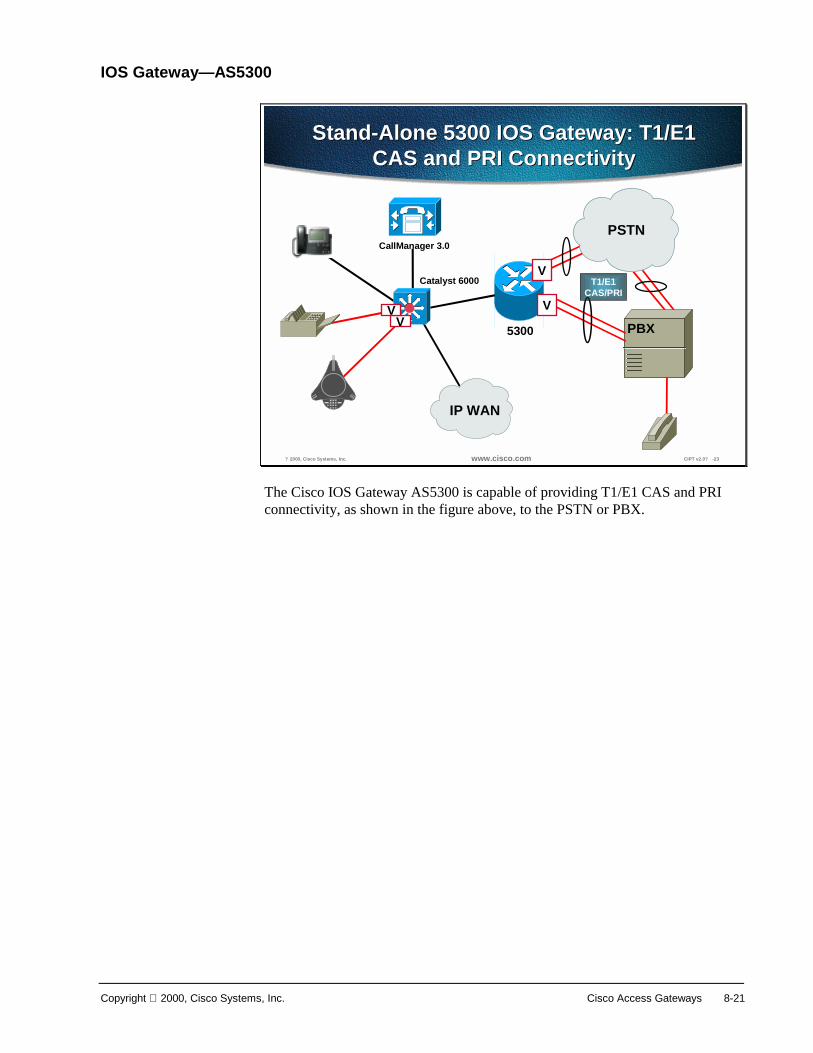
Copyright 2000, Cisco Systems, Inc. Cisco Access Gateways 8-21
IOS Gateway—AS5300
? 2000, Cisco Systems, Inc. www.cisco.com CIPT v2.0? -23
Stand-Alone 5300 IOS Gateway: T1/E1CAS and PRI Connectivity
Stand-Alone 5300 IOS Gateway: T1/E1CAS and PRI Connectivity
PBX
CallManager 3.0
T1/E1CAS/PRI
V
V
PSTN
IP WAN
V
Catalyst 6000
V5300
The Cisco IOS Gateway AS5300 is capable of providing T1/E1 CAS and PRI connectivity, as shown in the figure above, to the PSTN or PBX.

8-22 Cisco IP Telephony Copyright 2000, Cisco Systems, Inc.
DT-24+/DE-30+
? 2000, Cisco Systems, Inc. www.cisco.com CIPT v2.0? -24
DT-24+/DT-30+ Stand-AloneGateways
DT-24+/DT-30+ Stand-AloneGateways
• T1/E1 PRI• User/network side ISDN• Skinny gateway
– Supplementary services– Out-of-band DTMF– CCM failover
• G.711/G.723.1
The DT-24+/DE-30+, that replaced the DT-24 and DE 30 respectively, are capable of T1/E1 PRI, user/network side ISDN and G.711/G.732.1. The DT-24+/DE-30+ are skinny gateways the provide the following services:
■ Supplementary services (hold, transfer, and so forth)
■ Out-of-band DTMF
■ Cisco CallManager failover

Copyright 2000, Cisco Systems, Inc. Cisco Access Gateways 8-23
MGCP and VG200
? 2000, Cisco Systems, Inc. www.cisco.com CIPT v2.0? -25
VG200 Stand-Alone GatewayVG200 Stand-Alone Gateway
VG200 GCP mode
• 2xFXS/2xFXO• Analog only• NO FAX-relay .711 FAX support only
VG200 .323v2 mode
• T1/E1 AS, FXS, FXO, and E&M
The Voice Gateway 200 (VG200) replaces the analog stations and analog trunks. In the MGCP mode, the VG200 is capable of providing the following:
■ 2xFXS/2xFXO
■ Analog only
■ G.711 FAX support only—no FAX-relay
When the VG200 is using H.323v2 mode, it is capable of T1/E1 CAS, FXS, FXO, and E&M.

8-24 Cisco IP Telephony Copyright 2000, Cisco Systems, Inc.
? 2000, Cisco Systems, Inc. www.cisco.com CIPT v2.0? -26
High Level ConceptsHigh Level Concepts
• Media Gateway (MG) contains simple endpoints• Services provided by intelligent Media Gateway
Controller (MGC) or Call Agent (CA)• Endpoint provides user interactions and interfaces;
MGC provides centralized call intelligence• Master/slave relationship between MGC and MG• Simple endpoint executes small set of simple
transactions as instructed by MGC• New services introduced by MGC• Inexpensive endpoint can be mass-produced
What is MGCP? Media Gateway (MG) contains simple endpoints Services provided by an intelligent Media Gateway Controller (MGC) or Call Agent(CA). The endpoints provide users interactions and interfaces and the MGC provides centralized call intelligence. Between MGC and MG there is master/slave relationship. This simple endpoint executes a small set of simple transactions as instructed by MGC.
New services will be introduced to MGC and it is an inexpensive endpoint that can be mass produced.

Copyright 2000, Cisco Systems, Inc. Cisco Access Gateways 8-25
MGCP Basics
? 2000, Cisco Systems, Inc. www.cisco.com CIPT v2.0? -27
MGCP BasicsMGCP BasicsMGCP Basics
• Endpoints pecific trunk/port or service, such as an
announcement server• Connections� modes: send, receive, send/receive,
inactive, loopback, continuity test• Calls roupings of connections
• Call Agents entralized intelligence
The following are the basic concepts and terms used with MGCP:
■ Endpoints—specific trunk/port or service, such as an announcement server
■ Connections—modes: send, receive, send/receive, inactive, loopback, continuity test
■ Calls—groupings or connections
■ Call Agents—centralized intelligence

8-26 Cisco IP Telephony Copyright 2000, Cisco Systems, Inc.
MGCP Primitives
? 2000, Cisco Systems, Inc. www.cisco.com CIPT v2.0? -28
MGCP PrimitivesMGCP PrimitivesMGCP Primitives
• NotificationRequest (RQNT) nstructs the gateway to watch for specificevents
• Notify (NTFY) nform MGC when requested events occur
• CreateConnection (CRCX) reate a connection to an ndpoint? inside the gateway
• ModifyConnection (MDCX) hange the parameters associated with anestablished connection
• DeleteConnection elete an existing connection ck returns call statistics
• AuditEnpoint (AUEP) udit an existing endpoint
• AuditConnection (AUCX) udit an existing connection
• RestartInProgress (RSIP) ateway notification to the MGC that a MG orendpoint is restarting or stopping
The MGCP primitives are the components that allow CIPT to discontinue its dependence on software MTP. The emerging standard has been proposed by Cisco as a means to counter some limitations of the H.323 protocol suite.
The following are MGCP primitive terms and definitions:
■ NotificationRequest (RQNT)—Instructs the gateway to watch for specific events
■ Notify (NTFY)—Inform MGC when requested events occur
■ CreateConnection (MDCX)—Change the parameters associated with an established connection
■ DeleteConnection—Delete an existing connection—Ack returns call statistics
■ AuditEndpoint (AUEP)—Audit an existing endpoint
■ AuditConnection (AUCX)—Audit an existing connection
■ RestartInProgress (RSIP)—Gateway notifiction to the MGC that a MG or endpoint is restarting or stopping

Copyright 2000, Cisco Systems, Inc. Cisco Access Gateways 8-27
? 2000, Cisco Systems, Inc. www.cisco.com CIPT v2.0? -29
MGCP StartupMGCP Startup
VRSIP
200 OK
RQNT
200 OK
AUEP (parms)
200 OK (results)
CallManager VG200
The figure above shows the communication between the Cisco CallManager and VG200 using MGCP on startup. The process is as follows:
1. RestartInProgress (RSIP) is sent from the VG200 to the Cisco CallManager telling the Cisco CallManager an endpoint is restarting or starting up.
2. The Cisco CallManager acknowledges with a 200 OK.
3. The Cisco CallManager sends a NotificationRequest (RQNT) to the VG 200 instructing the gateway to watch for specific events.
4. The VG200 acknowledges with a 200 OK.
5. Cisco CallManager sends an AuditEndpoint (AUEP) in order to audit the existing endpoint (VG200).
6. The VG200 acknowledges with a 200 OK with the results of the audit.

8-28 Cisco IP Telephony Copyright 2000, Cisco Systems, Inc.
? 2000, Cisco Systems, Inc. www.cisco.com CIPT v2.0? -30
MGCP FXS CallMGCP FXS Call
V
NTFY O: L/hd
RQNT R: L/hu,D/[0-9*#] S:dl
NTFY O: 4
RQNT R: L/hu, D/[0-9*#] S:
NTFY O: 5
CRCX
CallManager VG200
MDCX
200 OK (RTP Port Info)
The figure above shows the procedure when a MGCP makes an FXS Call. The procedure is as follows:
1. The FXS phone goes offhook, GW sends notify (NTFY) for offhook event.
2. Cisco CallManager sends request notify (RQNT) with digit map and signal to turn on dial tone. CallManager requests each digit is sent individually (not accumulated).
3. User presses first digit.
4. NTFY sent to Cisco CallManager, Cisco CallManager sends RQNT to turn off dial tone.
5. User sends digit.
6. Cisco CallManager sends create connection (CRCX) to create a call leg. GW sends response with RTP SDP parameters (IP address and port for audio stream). Cisco CallManager sets up connection with remote RTP endpoint and starts ringing tone to caller.
7. Cisco CallManager sends modify connection (MDCX) to caller, setting IP address and port of other RTP endpoint. (MDCX can also set local send/receive state.)

Copyright 2000, Cisco Systems, Inc. Cisco Access Gateways 8-29
Adding an MGCP Gateway
? 2000, Cisco Systems, Inc. www.cisco.com CIPT v2.0? -31
Adding MGCPAdding MGCP
To use the Cisco VG200 with MGCP, you must use the FXO or FXS analog ports.
Before using Cisco CallManager, you must configure the Cisco VG200 gateway using the Cisco IOS command line interface (CLI). The procedures and commands required to perform this configuration are described in the Software Configuration Guide for the VG200 Gateway. More of the installation and configuration of the VG200 will be done during the lab time.
The procedure is as follows:
1. Open Cisco CallManager.
2. Select Device > Add a New Device. The Add Device screen appears.
3. Select Device Type > MGCP Gateway.
4. Click Next.
5. Enter the appropriate settings, as described in the MGCP Configuration Settings table (slot 0 is not used on the VG200.)

8-30 Cisco IP Telephony Copyright 2000, Cisco Systems, Inc.
MGCP Configuration Settings
Field Description Usage Notes
MGCP Domain Name Uniquely identifies the VG 200 gateway.
Use the Domain Name Service (DNS) host name if it is configured to resolve correctly. Otherwise use the IP address. You must use the same value here that is used to configure the VG200 at the IOS command line.
Description Clarifies purpose of device.
VIC in Slot 1/Sub-Unit 0 The type of Voice Interface Card installed in the right side of the VG200 voice network module, which resides in Slot 1.
If there is an FXS or an FXO VIC installed in Slot 1/Sub0Unit 0, then select the installed VIC Type. Slot 0 is not used on the VG200.
VIC in Slot 1 / Sub-Unit 1 The type of Voice Interface Card installed in the left side of the VG200 voice network module, which resides in Slot 1.
If there is an FXS or an FXO VIC installed in Slot 1/Sub0Unit 1, then select the installed VIC Type. Slot 0 is not used on the VG200.
6. Click Insert.

Copyright 2000, Cisco Systems, Inc. Cisco Access Gateways 8-31
? 2000, Cisco Systems, Inc. www.cisco.com CIPT v2.0? -32
CallManager3.0
uOne GateServer
Out-of-band DTMF viaMGCP ode out-off-band�
Compressed Voice Stream Skinny Station Protocol MGCP
Out-of-band DTMF viaskinny station protocol
PSTNDigital VG200
V
MGCP eliminates software MTP
FXS/FXO
mgcp dtmf-relay codec all mode out-of-bandmgcp dtmf-relay codec all mode out-of-band
VG200: DTMF SignalingInteraction
VG200: DTMF SignalingInteraction
The figure above shows the VG200 and DTMF signaling interaction. Between the Cisco CallManager and the VG200 there is an out-of-band DTMF signal via the MGCP “mode out-off-band.” The Cisco CallManager and Cisco uOne GateServer use skinny station protocol to us out-of-band DTMF. The MGCP eliminates the software MTP by compressing the voice stream between the VG200 and the Cisco uOne Gateserver.

8-32 Cisco IP Telephony Copyright 2000, Cisco Systems, Inc.
? 2000, Cisco Systems, Inc. www.cisco.com CIPT v2.0? -33
Out-of-Band DTMFOut-of-Band DTMF
This screen is the MGCP Member Configuration page from the Cisco CallManager administration pages. The MGCP member information defines the MGCP with a description, Device Pool, and Calling Search Space. Port Information is defined through the Prefix Directory Number (DN), the Number of Digits, and Expected number of digits to be received. The DTMF capabilities for this member is where you would determine the out-of-band send/receive capabilities for the VG200.

Copyright 2000, Cisco Systems, Inc. Cisco Access Gateways 8-33
© 2000, Cisco Systems, Inc. www.cisco.com CIPT v2.0—8-34
VG200: MGCP CCM Failover: “Transfer” RequestSkinnyStation
MGCP VoiceStream
VG200
CallManager
PSTNV
VG200
CallManager
PSTNV
TCP KeepAlive
XX
X
The VG200 uses MGCP to allow supplementary services. MGCP allows for VG200 and CallManager integration without the use of software MTP that allows for greater scalability.
The MGCP support is for analog FXS and FXO interfaces only.
The figure above left shows a MGCP initial call going direct from the gateway to the IP phone with no MTP required.
The figure above right shows the call being transferred, which is allowed using MGCP.
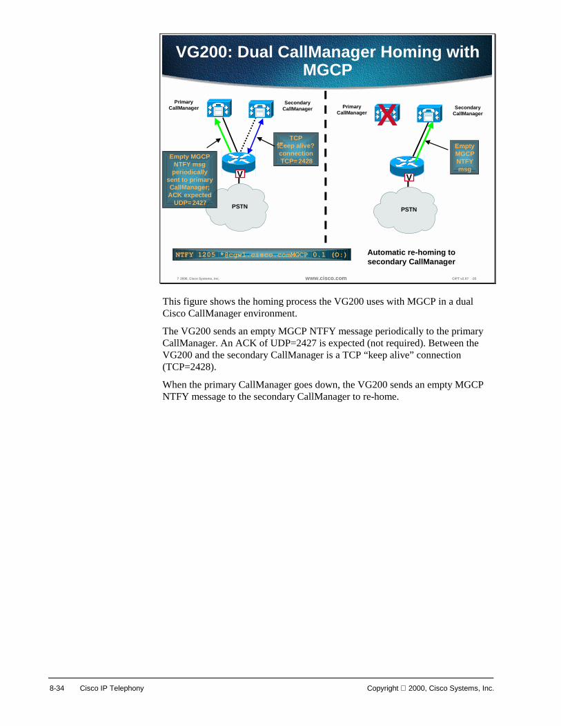
8-34 Cisco IP Telephony Copyright 2000, Cisco Systems, Inc.
? 2000, Cisco Systems, Inc. www.cisco.com CIPT v2.0? -35
VG200: Dual CallManager Homing withMGCP
PrimaryCallManager
SecondaryCallManager
V
PSTN
PrimaryCallManager
SecondaryCallManagerX
V
PSTN
Automatic re-homing tosecondary CallManager
TCPeep alive?
connectionTCP=2428Empty MGCP
NTFY msgperiodically
sent to primaryCallManager;ACK expected
UDP=2427
EmptyMGCPNTFYmsg
NTFY 1205 *@cgw1.cisco.comMGCP 0.1 (O:)
This figure shows the homing process the VG200 uses with MGCP in a dual Cisco CallManager environment.
The VG200 sends an empty MGCP NTFY message periodically to the primary CallManager. An ACK of UDP=2427 is expected (not required). Between the VG200 and the secondary CallManager is a TCP “keep alive” connection (TCP=2428).
When the primary CallManager goes down, the VG200 sends an empty MGCP NTFY message to the secondary CallManager to re-home.
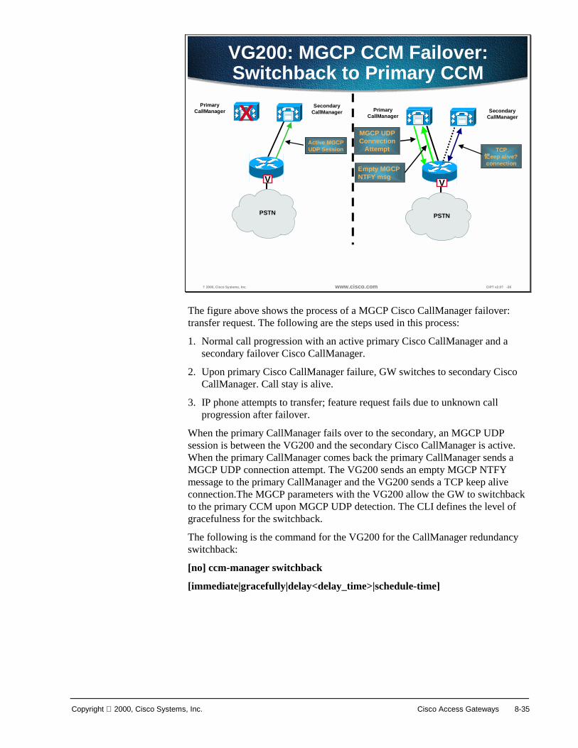
Copyright 2000, Cisco Systems, Inc. Cisco Access Gateways 8-35
? 2000, Cisco Systems, Inc. www.cisco.com CIPT v2.0? -36
VG200: MGCP CCM Failover:Switchback to Primary CCM
PrimaryCallManager
SecondaryCallManager
V
PSTN
PrimaryCallManager
SecondaryCallManagerX
V
PSTN
Active MGCPUDP Session
MGCP UDPConnection
Attempt TCPeep alive?
connectionEmpty MGCP NTFY msg
The figure above shows the process of a MGCP Cisco CallManager failover: transfer request. The following are the steps used in this process:
1. Normal call progression with an active primary Cisco CallManager and a secondary failover Cisco CallManager.
2. Upon primary Cisco CallManager failure, GW switches to secondary Cisco CallManager. Call stay is alive.
3. IP phone attempts to transfer; feature request fails due to unknown call progression after failover.
When the primary CallManager fails over to the secondary, an MGCP UDP session is between the VG200 and the secondary Cisco CallManager is active. When the primary CallManager comes back the primary CallManager sends a MGCP UDP connection attempt. The VG200 sends an empty MGCP NTFY message to the primary CallManager and the VG200 sends a TCP keep alive connection.The MGCP parameters with the VG200 allow the GW to switchback to the primary CCM upon MGCP UDP detection. The CLI defines the level of gracefulness for the switchback.
The following is the command for the VG200 for the CallManager redundancy switchback:
[no] ccm-manager switchback
[immediate|gracefully|delay<delay_time>|schedule-time]

8-36 Cisco IP Telephony Copyright 2000, Cisco Systems, Inc.
? 2000, Cisco Systems, Inc. www.cisco.com CIPT v2.0? -37
VG200-MGCP: Legacy Voice MailIntegration
VG200-MGCP: Legacy Voice MailIntegration
Voice Mail
Analog VG200
SMDI
FXS Lines
CallManager 3.0
The VG200-MGCP integration with legacy voice mail allows the Cisco CallManager to associate a port with a voice messaging mailbox and connection and is widely homologated.
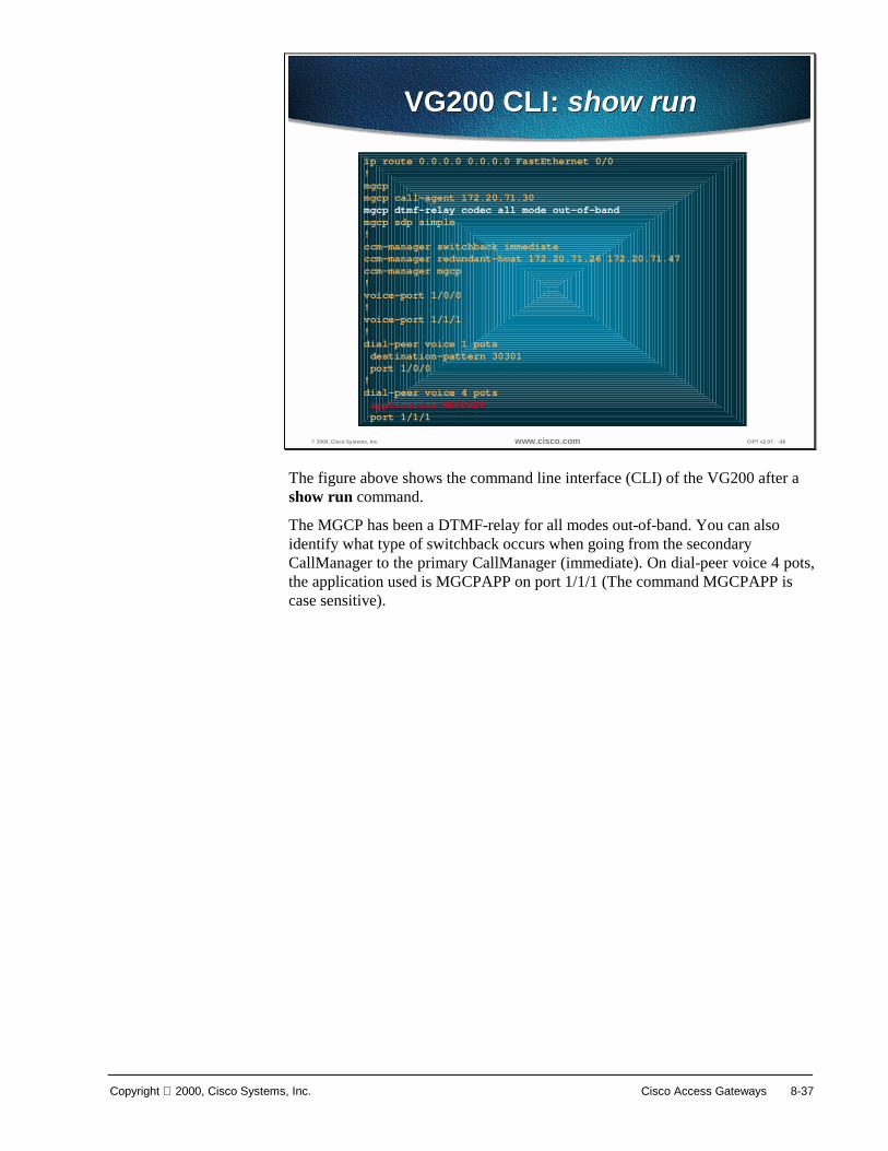
Copyright 2000, Cisco Systems, Inc. Cisco Access Gateways 8-37
? 2000, Cisco Systems, Inc. www.cisco.com CIPT v2.0? -38
VG200 CLI: show runVG200 CLI: show run
ip route 0.0.0.0 0.0.0.0 FastEthernet 0/0!mgcpmgcp call-agent 172.20.71.30mgcp dtmf-relay codec all mode out-of-bandmgcp sdp simple!ccm-manager switchback immediateccm-manager redundant-host 172.20.71.26 172.20.71.47ccm-manager mgcp!voice-port 1/0/0!voice-port 1/1/1!dial-peer voice 1 potsdestination-pattern 30301port 1/0/0
!dial-peer voice 4 potsapplication MGCPAPPport 1/1/1
The figure above shows the command line interface (CLI) of the VG200 after a show run command.
The MGCP has been a DTMF-relay for all modes out-of-band. You can also identify what type of switchback occurs when going from the secondary CallManager to the primary CallManager (immediate). On dial-peer voice 4 pots, the application used is MGCPAPP on port 1/1/1 (The command MGCPAPP is case sensitive).

8-38 Cisco IP Telephony Copyright 2000, Cisco Systems, Inc.
? 2000, Cisco Systems, Inc. www.cisco.com CIPT v2.0? -39
MGCP Port ConfigurationMGCP Port Configuration
1
2
MGCP port configuration is done through the MGCP configuration within the Cisco CallManager administration. Prior to configuring MGCP ports on the VG200, you have to add a MGCP gateway in the Cisco CallManager administration. Select which MGCP gateway to configure from the left side bar as shown in the figure above. Next, select the endpoint identifier you would like to configure.

Copyright 2000, Cisco Systems, Inc. Cisco Access Gateways 8-39
? 2000, Cisco Systems, Inc. www.cisco.com CIPT v2.0? -40
Assigning a Directory NumberAssigning a Directory Number
After you have selected your endpoint identifier, select Add DN from the left column. A new window will appear that you will be able to assign a directory number for the port you selected.
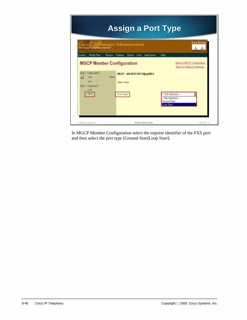
8-40 Cisco IP Telephony Copyright 2000, Cisco Systems, Inc.
? 2000, Cisco Systems, Inc. www.cisco.com CIPT v2.0? -41
Assign a Port TypeAssign a Port Type
In MGCP Member Configuration select the enpoint identifier of the FXS port and then select the port type [Ground Start|Loop Start].
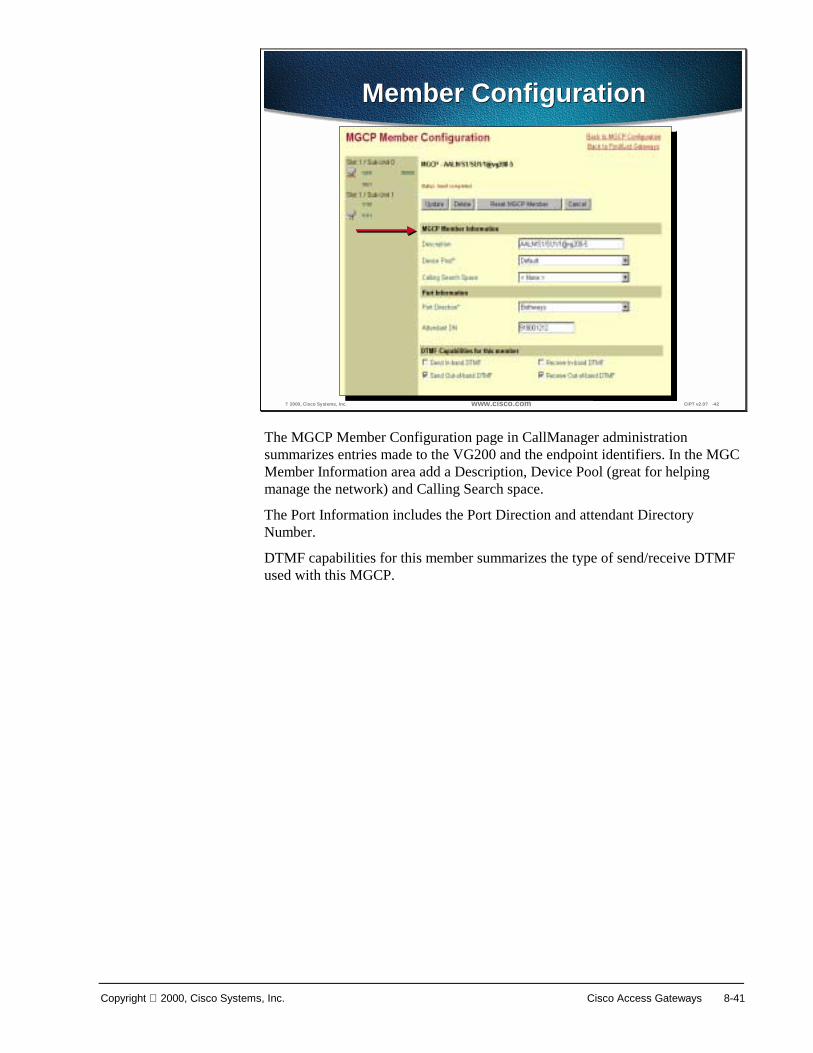
Copyright 2000, Cisco Systems, Inc. Cisco Access Gateways 8-41
? 2000, Cisco Systems, Inc. www.cisco.com CIPT v2.0? -42
Member ConfigurationMember Configuration
The MGCP Member Configuration page in CallManager administration summarizes entries made to the VG200 and the endpoint identifiers. In the MGC Member Information area add a Description, Device Pool (great for helping manage the network) and Calling Search space.
The Port Information includes the Port Direction and attendant Directory Number.
DTMF capabilities for this member summarizes the type of send/receive DTMF used with this MGCP.

8-42 Cisco IP Telephony Copyright 2000, Cisco Systems, Inc.
Integrated Router Gateways
© 2000, Cisco Systems, Inc. www.cisco.com CIPT v2.0—8-43
CallManager3.0
uOne GateServer
IOS Gateways: H.323v2 and DTMF Interaction
IOS 12.0(7)T out-of-bandDTMF relay via H.245
Out-of-band DTMF viaskinny station protocol
PSTNIOS gateway
V
H.323v2 eliminates software MTP
T1-CAS
Compressed Voice Stream Skinny Station Protocol H.323v2
dtmf-relay h245-alphanumeric
The IOS router gateways use the IOS 12.0(7)T out-of-band DTMF relay via H.245 to communicate with the CallManager. The IOS router gateways use H.323v2, which eliminates the need for software MTP.

Copyright 2000, Cisco Systems, Inc. Cisco Access Gateways 8-43
© 2000, Cisco Systems, Inc. www.cisco.com CIPT v2.0—8-44
IOS Gateways: H.323v2 and Supplementary Services
IOS GW
CallManager 3.0
1. Allows for IOS GW/Call Manager Integration without MTP (great1. Allows for IOS GW/Call Manager Integration without MTP (greater scalability)er scalability)2.2. H.323v2 and H.245 DTMF Relay require a minimum of 12.0(7)T and CH.323v2 and H.245 DTMF Relay require a minimum of 12.0(7)T and CCM 3.0CM 3.0
PSTNV
Design Characteristics
IOS GW
CallManager 3.0
PSTNV
Initial Call—Direct from GW to IP phoneNo MTP required
Call Transfer—Allow supplementary services
SkinnyStation
H.323v2 VoiceStream
IOS router gateways use the H.323v2 that allows for gateway to CallManager integration without MTP and provides for greater scalability. In order to use H.323v2 and H.245 DTMF relay you must have a minimum of Cisco IOS 12.0(7)T and Cisco CallManager 3.0.

8-44 Cisco IP Telephony Copyright 2000, Cisco Systems, Inc.
? 2000, Cisco Systems, Inc. www.cisco.com CIPT v2.0? -45
H.323v2 CallManagerRedundancy CLI Commands
H.323v2 CallManagerRedundancy CLI Commands
Router(config)#dial-peer voice 101 voipdestination-pattern 1111session target ipv4:10.1.1.101preference 0voice class h323 1dtmf-relay h245-alphanumeric
Router(config)#dial-peer voice 102 voipdestination-pattern 1111session target ipv4:10.1.1.102preference 1voice class h323 1dtmf-relay h245-alphanumeric
Router(config)#voice class h323 1h225 tcp timeout <1-30 sec>
The figure above shows the H.323v2 Cisco CallManager redundancy CLI commands.

Copyright 2000, Cisco Systems, Inc. Cisco Access Gateways 8-45
? 2000, Cisco Systems, Inc. www.cisco.com CIPT v2.0? -46
3810 VoIP 12.0(7)XK? 2.1(2)T3810 VoIP 12.0(7)XK? 2.1(2)T
• Use the 3810-V3–Only the HCM card can support
DTMF-relay• G.711, G.723.1, G.729• FXS, FXO, E&M, T1/E1 CAS, T1/E1 QSIG
The Cisco 3810 router is one of the IOS gateways that can be used in the Cisco IP Telephony Network. Use the 3810 version 3 and only the High Compression Module (HCM) card can support DTMF-relay. The Cisco 3810 supports G.711, G.723.1, and G.729 codec. The Cisco 3810 can accommodate FXS, FXO, E & M, T1/E1 CAS, and T1/E1 QSIG.

8-46 Cisco IP Telephony Copyright 2000, Cisco Systems, Inc.
? 2000, Cisco Systems, Inc. www.cisco.com CIPT v2.0? -47
2600/3600 MGCP Update2600/3600 MGCP Update
• H.323v2• Analog MGCP 12.1(3)T CM support in 3.0(1)
• FXO battery reversal detection on disconnect• T1/E1 QSIG 12.0(7)XK• T1/E1 PRI 12.1(2)T
The Cisco Routers 2600/3600 can support the following features that work in the Cisco IP Telephony Network:
■ H.323v2
■ Analog MGCP 12.1(3)T—Cisco CallManager support in 3.0(1)
■ FXO battery reversal detection on disconnect
■ T1/E1 QSIG 12.0(7)XK
■ T1E1 PRI 12.1(2)T
The following tables are quick reference guides to the Cisco H.323 gateways for the following topics:
■ PSTN interfaces
■ QoS and PPP
■ QoS and frame relay

Copyright 2000, Cisco Systems, Inc. Cisco Access Gateways 8-47
The table represents the H.323 gateway PSTN Interfaces:
? 2000, Cisco Systems, Inc. www.cisco.com CIPT v2.0? -48
H.323 Gateway PSTN InterfacesH.323 Gateway PSTN Interfaces
Gateway DataInterfaces
Analog PSTNInterfaces
Digital PSTNInterfaces in
DS0s
VoiceCompression
*1750 Ethernet,T1/E1
Serial4 0 G.711, G.729
2600 Ethernet,FastEthernet,Token Ring,
T1/E1 Serial andT1-OC3 ATM
4 48/60 G.711, G.729,G.729a, G.723.1
3620 Ethernet,FastEthernet,Token Ring,
T1/E1 Serial andT1-OC3 ATM
4 48/60 G.711, G.729,G.729a, G.723.1
3640 Ethernet,FastEthernet,Token Ring,
T1/E1 Serial andT1-OC3 ATM
12 136/180 G.711, G.729,G.729a, G.723.1
3660 10/100 EthernetToken Ring,
T1/E1 Serial andT1-OC3 ATM,
HSSI
24 288/360 G.711, G.729,G.729a, G.723.1
7200 10/100 EthernetToken Ring,
DS1-DS3 Serialand T1-OC3
ATM
0 288/360 G.711, G.729,G.729a, G.723.1
7500 Future

8-48 Cisco IP Telephony Copyright 2000, Cisco Systems, Inc.
The following table represents the Cisco H.323 gateway’s QoS that has VoIP over PPP:
? 2000, Cisco Systems, Inc. www.cisco.com CIPT v2.0? -49
H.323 Gateway QoS: PPPH.323 Gateway QoS: PPP
VoIP over PPP Quality of Service MatrixGateway LFI/MLPPP LLQ (PQ-CB-
WFQ)IP RTPPriority
CRTP - Fast/CEFswitched
GTS RSVP
1750 12.0(5)XQ1 12.1(2)T 12.1(1)T 12.1(1)T 12.0(5)XQ1 Yes
3810 V3 12.0(7)XK 12.0(7)XK 12.0(7)XK 12.0(7)XK 12.0(7)XK 12.0(7)XK2600 Yes Yes Yes Yes* Yes Yes
3620-40 Yes Yes Yes Yes* Yes Yes3660 Yes Yes Yes Yes* Yes Yes7200 Yes Yes Yes Yes* Yes Yes7500
DistributedFuture Future Future dCEF in 12.1(4)T 12.1(3)T RSVP runs
on RSP* Limited support in 12.0(7)XK, more support in 12.1(1)T

Copyright 2000, Cisco Systems, Inc. Cisco Access Gateways 8-49
The following table shows the H.323 gateways QoS use with frame relay:
? 2000, Cisco Systems, Inc. www.cisco.com CIPT v2.0? -50
H.323 Gateway QoS: FrameRelay
H.323 Gateway QoS: FrameRelay
VoIP over Frame-Relay Quality of ServiceGateway FRF.12 LLQ (PQ-
CB-WFQ)per VC
CRTP - Fast/CEFswitched
FRTS GTS RSVP IP RTPPriority
1750 12.0(5)XQ1 12.1(2)T 12.1(1)T 12.0(5)XQ1 12.0(5)XQ1 Yes 12.1(1)T3810 V3 Yes 12.1(2)T 12.0(7)XK Yes Yes Yes 12.0(7)XK
2600 Yes 12.1(2)T 12.0(7)T Yes Yes Yes Yes3620-40 Yes 12.1(2)T 12.0(7)T Yes Yes Yes Yes
3660 Yes 12.1(2)T 12.0(7)T Yes Yes Yes Yes7200 Yes 12.1(2)T 12.0(7)T Yes Yes Yes Yes7500
Distributed12.1(3)T 12.1(3)T dCEF in 12.1(4)T 12.1(3)T 12.1(3)T RSVP
runs onRSP
12.1(3)T
* Limited support in 12.0(7)XK, more support in 12.1(1)T
Note Catalyst gateways and DSP resources will be discussed later in this course.

8-50 Cisco IP Telephony Copyright 2000, Cisco Systems, Inc.
Single-Site Enterprise Deployments Choosing gateways for single-site enterprise deployments can be one of the more daunting tasks facing AVVID designers. A primary reason for this is balancing the density and feature requirements of the current environment with the future complexities of a growing business and rapidly evolving applications. This section will examine the requirements and detail the implementation specifics for several single-site enterprises: 100-500 users, 2,500 users, and 10,000 users. In all designs, G.711, or uncompressed, voice is used to provide the highest voice quality while enabling ease of configuration.
? 2000, Cisco Systems, Inc. www.cisco.com CIPT v2.0? -51
Single-Site EnterpriseCharacteristics
Single-Site EnterpriseCharacteristics
• G.711 voice on all gateways to eliminateconfiguration complexity and maximize voice qualityin a high bandwidth environment
• Because G.711 is used, there is no requirement forFAX-relay
• DTMF-relay is a design requirement for applicationinteraction
• Support for supplementary services such as hold,transfer and conference
• Support for CallManager failover in a clusteredenvironment
• As the size of the enterprise installation grows,hardware based conferencing
Single-Site/Campus Design Characteristics The following characteristics are part of a single site enterprise in regards to gateways:
■ G.711 voice on all gateways to eliminate configuration complexity and maximize voice quality in a high bandwidth environment
■ Because G.711 is used, there is no requirement for FAX-relay
■ DTMF-relay is a design requirement for application interaction
■ Support for supplementary services such as hold, transfer and conference
■ Support for CallManager failover in a clustered environment
■ As the size of the enterprise installation grows, hardware based conferencing

Copyright 2000, Cisco Systems, Inc. Cisco Access Gateways 8-51
? 2000, Cisco Systems, Inc. www.cisco.com CIPT v2.0? -52
Three Types of Single SiteDeployments
Three Types of Single SiteDeployments
• Small enterprise (<500 users)–Analog and/or digital trunks–No Legacy voice mail
Medium enterprise (500-2,500 users)–Legacy voice mail� VG200/WS-X6624-FXS–Digital trunks (CAS or PRI)
Large enterprise (2,500-10,000 users)–Legacy voice mail� VG200/WS-X6624-FXS–PRI–Central site for WAN deployments� QoS
The following are the three types of single site deployments:
■ Small enterprise (<500 users)
— Analog and/or digital trunks
— No Legacy voice mail
■ Medium enterprise (500-2500 users)
— Legacy voice mail—VG200/WS-X6624-FXS
— Digital Trunks (CAS or PRI)
■ Large enterprise (2,500—10,000 users)
— Legacy voice mail—VG200/WS-X6624-FXS
— PRI
— Central site for WAN deployments—QoS

8-52 Cisco IP Telephony Copyright 2000, Cisco Systems, Inc.
100-500 Users, Single-Site Enterprise
Analog PSTN Connectivity The single-site, small enterprise of 100 users or less is one of the most common AVVID implementations in the commercial sector. These sites will typically be Greenfield installations where an end-to-end Cisco solution can be easily provided.
? 2000, Cisco Systems, Inc. www.cisco.com CIPT v2.0? -53
Analog ConnectionConsiderations
Analog ConnectionConsiderations
• Use analog connection to PSTN when there is noother choice
• Use VIC-2FXO-M1 (-M2 for CE countries) if usingFXO interfaces to connect to the CO
• 4 port BRI VIC, the 2BRI-S/T-TE is another option toprovide DID support
The following are considerations is connecting analog to the PSTN:
■ Only use an analog connection to the PSTN when there is no other choice. When possible, connect to the PSTN using digital interfaces, preferably PRI.
■ If using FXO interfaces to connect to the PBX, use the VIC-2FXO-M1 (-M2 for CE countries), which provides the feature of battery reversal detection on far-end disconnect to help eliminate the disconnect problems common with some FXO interfaces.
■ Another option to provide DID support is the 4 ports BRI VIC, the 2BRI-S/T-TE. With 12.1(2)Xx, the 2600 and 3600 lines of IOS gateways provide calling-line ID on all telephony interfaces.

Copyright 2000, Cisco Systems, Inc. Cisco Access Gateways 8-53
Analog PSTN connectivity, fax support and voice mail, are among the common requirements in this type of small enterprise design. The example below depicts a 2600 IOS gateway containing four FXO voice interface cards (VICs) is used for PSTN connectivity. This will allow for a total of four analog lines from the central office switch for PSTN connectivity. If additional PSTN interfaces are needed or the enterprise wants to add fax support, either an IOS router/gateway with additional slots or a stand-alone AVVID gateway, the VG200, can be added to this design.
? 2000, Cisco Systems, Inc. www.cisco.com CIPT v2.0? -54
100 User, Single SiteEnterprise
100 User, Single SiteEnterpriseCall
ManageruOneGateserver
PSTN2xVIC-2FXO-M1
IP WANV
2600
StackableCatalyst 3500s
VG200 2xVIC-2FXSV
The above figure shows a 100 user, single-site enterprise.
Fitting the requirements of a small enterprise infrastructure is the Catalyst 4000 Ethernet switch. Shortly following the release of Cisco CallManager 3.0, the Catalyst 4000 will add support for providing line power to Cisco IP phones, Legacy telephony interfaces, IP-to-IP packet transcoding and conferencing services. Both transcoding and conferencing services will be addressed in later chapters. The Legacy telephony interfaces, however, are a vital piece in deploying the enterprise AVVID network. A Catalyst 4000 with the gateway module, the WS-X4604-GWY, can act as a PSTN gateway using analog or digital VIC interfaces or can be configured to provide six analog ports for GIII FAX machines or Polycom conferencing stations.

8-54 Cisco IP Telephony Copyright 2000, Cisco Systems, Inc.
Digital PSTN Connectivity
? 2000, Cisco Systems, Inc. www.cisco.com CIPT v2.0? -55
Digital PSTN ConnectivityConsiderations
Digital PSTN ConnectivityConsiderations
• Use PRI when possible using the DT-X+or Catalyst 6000 at CCM 3.0 FCS
• The 2600 and 3600 will have PRI in12.1(2)Xx
• The Catalyst 4000 will have both PRIand CAS at FCS
Consider the following when you have a digital connection to the PSTN:
■ Use PRI when possible using the DT-24+/DE-30+ or Catalyst 6000 with the Cisco CallManager 3.0 or higher.
■ The Cisco 2600 and 3600 will have PRI in 12.1(2)xx.
■ The Catalyst 4000 will have both PRI and CAS.
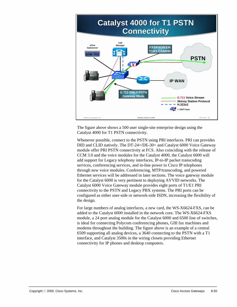
Copyright 2000, Cisco Systems, Inc. Cisco Access Gateways 8-55
? 2000, Cisco Systems, Inc. www.cisco.com CIPT v2.0? -56
Catalyst 4000 for T1 PSTNConnectivity
Catalyst 4000 for T1 PSTNConnectivity
CallManageruOne
Gateserver
PSTN
FXS/FXO/E&MT1/E1 CAS/PRI
G.711 ONLY PSTNGateway Mode
Skinny Station Protocol H.323v2
G.711 Voice Stream
V
IP WAN
V = DSP Farm
The figure above shows a 500 user single-site enterprise design using the Catalyst 4000 for T1 PSTN connectivity.
Whenever possible, connect to the PSTN using PRI interfaces. PRI can provides DID and CLID natively. The DT-24+/DE-30+ and Catalyst 6000 Voice Gateway module offer PRI PSTN connectivity at FCS. Also coinciding with the release of CCM 3.0 and the voice modules for the Catalyst 4000, the Catalyst 6000 will add support for Legacy telephony interfaces, IP-to-IP packet transcoding services, conferencing services, and in-line power to Cisco IP telephones through new voice modules. Conferencing, MTP/transcoding, and powered Ethernet services will be addressed in later sections. The voice gateway module for the Catalyst 6000 is very pertinent to deploying AVVID networks. The Catalyst 6000 Voice Gateway module provides eight ports of T1/E1 PRI connectivity to the PSTN and Legacy PBX systems. The PRI ports can be configured as either user-side or network-side ISDN, increasing the flexibility of the design.
For large numbers of analog interfaces, a new card, the WS-X6624-FXS, can be added to the Catalyst 6000 installed in the network core. The WS-X6624-FXS module, a 24 port analog module for the Catalyst 6000 and 6500 line of switches, is ideal for connecting Polycom conferencing phones, GIII fax machines and modems throughout the building. The figure above is an example of a central 6509 supporting all analog devices, a 3640 connecting to the PSTN with a T1 interface, and Catalyst 3500s in the wiring closets providing Ethernet connectivity for IP phones and desktop computers.
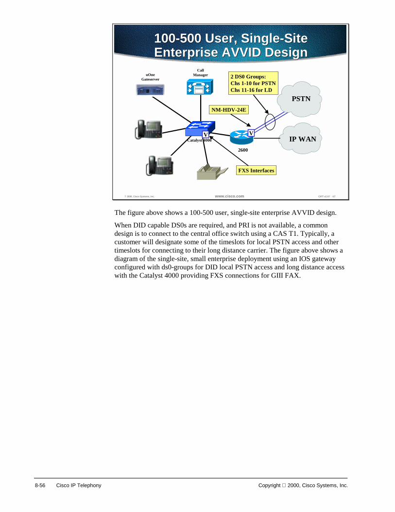
8-56 Cisco IP Telephony Copyright 2000, Cisco Systems, Inc.
? 2000, Cisco Systems, Inc. www.cisco.com CIPT v2.0? -57
100-500 User, Single-SiteEnterprise AVVID Design100-500 User, Single-SiteEnterprise AVVID Design
CallManageruOne
Gateserver
PSTNNM-HDV-24E
IP WANV
2600
Catalyst 4006
FXS Interfaces
V
2 DS0 Groups:Chs 1-10 for PSTNChs 11-16 for LD
The figure above shows a 100-500 user, single-site enterprise AVVID design.
When DID capable DS0s are required, and PRI is not available, a common design is to connect to the central office switch using a CAS T1. Typically, a customer will designate some of the timeslots for local PSTN access and other timeslots for connecting to their long distance carrier. The figure above shows a diagram of the single-site, small enterprise deployment using an IOS gateway configured with ds0-groups for DID local PSTN access and long distance access with the Catalyst 4000 providing FXS connections for GIII FAX.

Copyright 2000, Cisco Systems, Inc. Cisco Access Gateways 8-57
? 2000, Cisco Systems, Inc. www.cisco.com CIPT v2.0? -58
Sample Configuration fords0
Sample Configuration fords0
controller T1 1/0framing esflinecoding b8zsds0-group 1 timeslots 1-10 type ground-startds0-group 2 timeslots 11-16 type ground-startdial-peer voice 1 potsdestination-pattern 9? ?Port 1/0:1dial-peer voice 2 potsdestination-pattern 8? ? .port 1/0:2
controller T1 1/0framing esflinecoding b8zsds0-group 1 timeslots 1-10 type ground-startds0-group 2 timeslots 11-16 type ground-startdial-peer voice 1 potsdestination-pattern 9? ?Port 1/0:1dial-peer voice 2 potsdestination-pattern 8? ? .port 1/0:2
The figure above is a sample configuration for assigning ds0-groups in global configuration mode.

8-58 Cisco IP Telephony Copyright 2000, Cisco Systems, Inc.
? 2000, Cisco Systems, Inc. www.cisco.com CIPT v2.0? -59
Small Enterprise Gateway MatrixSmall Enterprise Gateway Matrix
Gateway Data Interfaces AnalogPSTN
Interfaces
Digital PSTNInterfaces in
DS0s
VoiceCompression*
VG200 Ethernet 4 0 G.711, G.729,G.729a, G.723.1
2600 Ethernet, FastEthernet,Token Ring, T1/E1
Serial and T1-OC3 ATM
4 48/60 G.711, G.729,G.729a, G.723.1
3620 Ethernet, FastEthernet,Token Ring, T1/E1
Serial and T1-OC3 ATM
4 48/60 G.711, G.729,G.729a, G.723.1
3640 Ethernet, FastEthernet,Token Ring, T1/E1
Serial and T1-OC3 ATM
12 136/180 G.711, G.729,G.729a, G.723.1
Catalyst 4000 Ethernet, FastEthernet,GigabitEthernet,T1/E1
Serial
6 48/60 G.711***
Catalyst 6000 Ethernet, FastEthernet,GigabitEthernet, OC12,Selected 7200 PAs**
120192
960/12001536/1920
G.711***
A 100-500 user, small enterprise gateway matrix is detailed in the table above. The new VG200 stand-alone gateway, Catalyst 4000 WS-X4606-GWY, and Catalyst 6000 WS-X6608 are listed as well as the traditional IOS gateway. Note that the Voice Compression column only lists the codecs that are pertinent in AVVID architectures. The IOS gateways support many more compression algorithms, however, Cisco CallManager devices only support G.711, G.729, G.723.1, or G.729/729a.
* Voice compressions listed as pertinent to AVVID networks only.
** With the WS-6182-2PA
*** Using the MTP transcoding feature, G.729a and G.723.1 can also be supported.
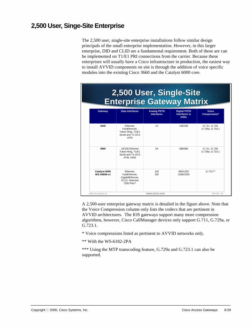
Copyright 2000, Cisco Systems, Inc. Cisco Access Gateways 8-59
2,500 User, Singe-Site Enterprise
The 2,500 user, single-site enterprise installations follow similar design principals of the small enterprise implementation. However, in this larger enterprise, DID and CLID are a fundamental requirement. Both of these are can be implemented on T1/E1 PRI connections from the carrier. Because these enterprises will usually have a Cisco infrastructure in production, the easiest way to install AVVID components on site is through the addition of voice specific modules into the existing Cisco 3660 and the Catalyst 6000 core.
? 2000, Cisco Systems, Inc. www.cisco.com CIPT v2.0? -60
2,500 User, Single-SiteEnterprise Gateway Matrix
2,500 User, Single-SiteEnterprise Gateway Matrix
Gateway Data Interfaces Analog PSTNInterfaces
Digital PSTNInterfaces in
DS0s
VoiceCompression*
3640 Ethernet,FastEthernet,
Token Ring, T1/E1Serial and T1-OC3
ATM
12 136/180 G.711, G.729,G.729a, G.723.1
3660 10/100 EthernetToken Ring, T1/E1Serial and T1-OC3
ATM, HSSI
24 288/360 G.711, G.729,G.729a, G.723.1
Catalyst 6000WS-X6608-x1
Ethernet,FastEthernet,
GigabitEthernet,OC12, Selected
7200 PAs**
120192
960/12001536/1920
G.711***
A 2,500-user enterprise gateway matrix is detailed in the figure above. Note that the Voice Compression column only lists the codecs that are pertinent in AVVID architectures. The IOS gateways support many more compression algorithms, however, Cisco CallManager devices only support G.711, G.729a, or G.723.1.
* Voice compressions listed as pertinent to AVVID networks only.
** With the WS-6182-2PA
*** Using the MTP transcoding feature, G.729a and G.723.1 can also be supported.

8-60 Cisco IP Telephony Copyright 2000, Cisco Systems, Inc.
10,000 User, Single-Site Enterprise
? 2000, Cisco Systems, Inc. www.cisco.com CIPT v2.0? -61
10,000 User EnterpriseCampus Design
10,000 User EnterpriseCampus Design
Buildings
Campus / MANBackbone
CallManager Cluster
Voice Mail
PSTN
Catalyst 6000s
Catalyst 6500s
Catalyst6500s
FXS Lines
SMDI
WS-X6608-x1 T1/E1 PRI
Large enterprises place much higher demands upon an AVVID design, particularly the gateways. These customers require multiple digital PSTN connections that can provide DID support. Additionally, AVVID installations in these large environments will be phased, requiring an extended time of interoperability with both Legacy PBX systems and voice mail servers. In many instances, these customers are relying on 7200 and 7500 IOS router platforms for their production networks. The large enterprise customer can leverage these existing 7200 and 7500 chassis in the AVVID design by adding Voice over IP port adapters (PAs), the PA-VXC-2TE1, for T1/E1 CAS PSTN and PBX connectivity. These VoIP PAs support 2 T1/E1 CAS each and can provide significant density. The 7200 supports both T1 and E1 CAS in 12.0(5)XE3. On the 7500, T1 and E1 CAS will be supported in 12.1(1)T. Both the 7200 and the 7500 will provide PRI support in 12.1(3)T. E1 R2 support will be added to the digital voice interfaces at the same time.
When both DID and CLID are required features, in either T1/E1 CAS or PRI implementations, another alternative is to add the Cisco 5300 as a stand-alone VoIP gateway. This solution provides the larger enterprises, with extremely tight downtime tolerances, the ability to add an AVVID architecture without any modifications to the existing IP infrastructure. The 5300 supports either T1/E1 CAS or PRI.
Note Cisco IOS 12.0(7)T is required to enable network-side ISDN. The VoIP enabled Cisco AS5300 is homologated for use most countries.
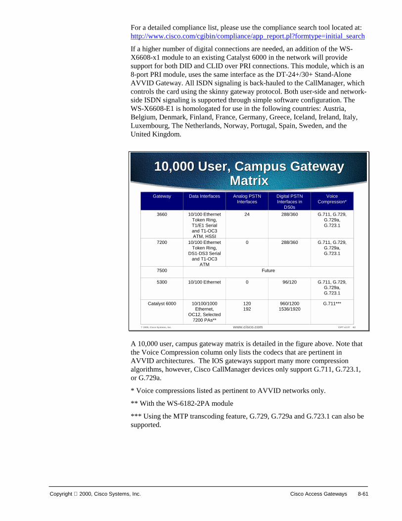
Copyright 2000, Cisco Systems, Inc. Cisco Access Gateways 8-61
For a detailed compliance list, please use the compliance search tool located at: http://www.cisco.com/cgibin/compliance/app_report.pl?formtype=initial_search
If a higher number of digital connections are needed, an addition of the WS-X6608-x1 module to an existing Catalyst 6000 in the network will provide support for both DID and CLID over PRI connections. This module, which is an 8-port PRI module, uses the same interface as the DT-24+/30+ Stand-Alone AVVID Gateway. All ISDN signaling is back-hauled to the CallManager, which controls the card using the skinny gateway protocol. Both user-side and network-side ISDN signaling is supported through simple software configuration. The WS-X6608-E1 is homologated for use in the following countries: Austria, Belgium, Denmark, Finland, France, Germany, Greece, Iceland, Ireland, Italy, Luxembourg, The Netherlands, Norway, Portugal, Spain, Sweden, and the United Kingdom.
? 2000, Cisco Systems, Inc. www.cisco.com CIPT v2.0? -62
10,000 User, Campus GatewayMatrix
10,000 User, Campus GatewayMatrix
Gateway Data Interfaces Analog PSTNInterfaces
Digital PSTNInterfaces in
DS0s
VoiceCompression*
3660 10/100 EthernetToken Ring,T1/E1 Serialand T1-OC3ATM, HSSI
24 288/360 G.711, G.729,G.729a,G.723.1
7200 10/100 EthernetToken Ring,
DS1-DS3 Serialand T1-OC3
ATM
0 288/360 G.711, G.729,G.729a,G.723.1
7500 Future
5300 10/100 Ethernet 0 96/120 G.711, G.729,G.729a,G.723.1
Catalyst 6000 10/100/1000Ethernet,
OC12, Selected7200 PAs**
120192
960/12001536/1920
G.711***
A 10,000 user, campus gateway matrix is detailed in the figure above. Note that the Voice Compression column only lists the codecs that are pertinent in AVVID architectures. The IOS gateways support many more compression algorithms, however, Cisco CallManager devices only support G.711, G.723.1, or G.729a.
* Voice compressions listed as pertinent to AVVID networks only.
** With the WS-6182-2PA module
*** Using the MTP transcoding feature, G.729, G.729a and G.723.1 can also be supported.

8-62 Cisco IP Telephony Copyright 2000, Cisco Systems, Inc.
Install and Configure Commands This section lists the steps and highlights the commands used to configure the various gateways.
Adding Analog Gateways
? 2000, Cisco Systems, Inc. www.cisco.com CIPT v2.0? -63
Adding an Analog GatewayAdding an Analog Gateway
• Cisco AS-2, AS-4, and AS-8 Gateways• Cisco AT-2, AT-4, and AT-8 Gateways• Cisco Catalyst 6000 24 Port FXS Gateway
The following Cisco analog gateways can be added to CallManager:
■ Cisco AS-2, AS-4, and AS-8 Gateways
■ Cisco AT-2, AT-4, and AT-8 Gateways
■ Cisco Catalyst 6000 24 Port FXS Gateway

Copyright 2000, Cisco Systems, Inc. Cisco Access Gateways 8-63
? 2000, Cisco Systems, Inc. www.cisco.com CIPT v2.0? -64
ProcedureProcedure
Select one of the following gatewaysSelect one of the following gateways
The figure above is a layered slide that demonstrates the cisco CallManager Administration pages you will use to add a Cisco analog gateway in the CallManager database. Use the following procedure:
1. Open Cisco CallManager.
2. Select Device > Add a New Device. The Add Device screen appears.
3. Select Device Type > Gateway.
4. Select the Gateway Type. Analog gateways include the following:
■ Cisco AS-2, AS-4, and AS-8 Gateways
■ Cisco AT-2, AT-4, and AT-8 Gateways
■ Cisco Catalyst 6000 24 Port FXS Gateway
5. Select Device Protocol > Access Analog.
6. Click Next. The Gateway Configuration screen appears.
See the following page that describes the analog gateway configuration settings.

8-64 Cisco IP Telephony Copyright 2000, Cisco Systems, Inc.
? 2000, Cisco Systems, Inc. www.cisco.com CIPT v2.0? -65
Cisco Access Analog GatewayConfiguration Settings
Cisco Access Analog GatewayConfiguration Settings
• MAC address—Identifies hardware-based telephones anddevice name
• Description—Clarifies the purpose of the device• Device pool—Specifies the collection of properties for this device
including CallManager group, date and time setting, region, andcalling search space for auto-registration of devices
• Load information—Specifies the custom software for gateway• Country code—The country in which the gateway is located• Location—Specifies the remote location accessed using restricted
bandwidth connections• Calling search space—Specifies the collection of route partitions
searched to determine how a dialed number should be routed• Port selection order—Specifies the order in which ports are
selected
7. Enter the appropriate settings, as described above and in the table on the following page, and then click Insert.

Copyright 2000, Cisco Systems, Inc. Cisco Access Gateways 8-65
The following table shows Cisco access analog gateway configuration settings.
Field Description Usage Notes
MAC Address Identifies hardware-based telephones and device name.
Value must be 12 hexadecimal characters.
Description Clarifies the purpose of the device.
Device Pool Specifies the collection of properties for this device including CallManager Group, Date and Time Setting, Region, and Calling Search Space for auto-registration of devices.
Load Information
Specifies the custom software for gateway. Values entered here override the default values for this gateway.
Country Code The country in which the gateway is located. Select the country in which the gateway is located from the drop-down selection box.
Location Specifies the remote location accessed using restricted bandwidth connections.
Calling Search Space
Specifies the collection of Route Partitions searched to determine how a dialed number should be routed.
Port Selection Order
Specifies the order in which ports are selected. TOP_DOWN selects ports in descending order, from port 1 to port 8. BOTTOM_UP selects ports in ascending order, from port 8 to port 1.
Valid entries are TOP_DOWN or BOTTOM_UP. If you're not sure which port order to use, choose TOP_DOWN.

8-66 Cisco IP Telephony Copyright 2000, Cisco Systems, Inc.
Adding Digital Gateways
? 2000, Cisco Systems, Inc. www.cisco.com CIPT v2.0? -66
Adding a Digital GatewayAdding a Digital Gateway
• Cisco DT-24+ Gateway• Cisco DE-30+ Gateway• Cisco Catalyst 6000 T1/E1 VoIP Gateway
The following are Cisco digital gateways you can add to CallManager:
■ Cisco DT-24 + Gateway
■ Cisco DE-30+ Gateway
■ Cisco Catalyst 6000 T1/E1 VoIP Gateway

Copyright 2000, Cisco Systems, Inc. Cisco Access Gateways 8-67
? 2000, Cisco Systems, Inc. www.cisco.com CIPT v2.0? -67
ProcedureProcedure
Select one of the following gatewaysSelect one of the following gateways
Use the following procedure to add Cisco digital gateways to CallManager:
1. Open Cisco CallManager.
2. Select Device > Add a New Device. The Add Device screen appears.
3. Select Device Type > Gateway.
4. Select the Gateway Type. Access Digital PRI gateways include:
■ Cisco DT-24+ Gateway
■ Cisco DT-24 Gateway
■ Cisco DE-30+ Gateway
■ Cisco Catalyst 6000 E1 VoIP Gateway
5. Click Insert.
6. Select Device Protocol > Access Digital PRI.
7. Click Next. The Gateway Configuration screen appears.

8-68 Cisco IP Telephony Copyright 2000, Cisco Systems, Inc.
? 2000, Cisco Systems, Inc. www.cisco.com CIPT v2.0? -68
Digital Gateway ConfigurationSettings
Digital Gateway ConfigurationSettings
Enter the appropriate settings as described in the following table and following pages, Access Digital PR1 Gateway Configuration Setting, on the next page.
8. Click Insert. The Gateway Configuration screen appears.

Copyright 2000, Cisco Systems, Inc. Cisco Access Gateways 8-69
Field Description Usage Notes
MAC Address Identifies hardware-based telephones and device name.
Value must be 12 hexadecimal characters.
Description Clarifies the purpose of the device.
Device Pool Specifies the collection of properties for this device including CallManager Group, Date and Time Setting, Region, and Calling Search Space for auto registration of devices.
Calling Search Space
Specifies the collection of route partitions searched to determine how a dialed number should be routed.
Location Remote location accessed using restricted bandwidth connections.
Load Information
Specifies the custom software for gateway. Values entered here override the default values for this gateway.
TX-Level CSU Specifies the transmit level based on the distance between the gateway and the nearest repeater. The default is full power (0dB).
Select one of the alternative settings to attenuate the line.
-7.5dB
-15dB
-22.5dB
Channel Selection Order
Specifies the order in which ports are enabled from first (lowest number port) to last (highest number port), or from last to first.
Valid entries are TOP_DOWN (last to first) or BOTTOM_UP (first to last). If you're not sure which port order to use, choose TOP_DOWN.
PCM Type Specifies the digital encoding format. Choose from the following:
A-law Use for Europe and the rest of the world
µ-law Use for North America

8-70 Cisco IP Telephony Copyright 2000, Cisco Systems, Inc.
© 2000, Cisco Systems, Inc. www.cisco.com CIPT v2.0—8-69
Configuration SettingsConfiguration Settings
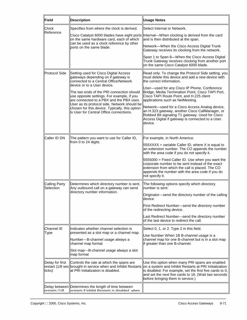
Copyright 2000, Cisco Systems, Inc. Cisco Access Gateways 8-71
Field Description Usage Notes
Clock Reference
Specifies from where the clock is derived.
Cisco Catalyst 6000 blades have eight ports on the same hardware card, each of which can be used as a clock reference by other ports on the same blade.
Select Internal or Network.
Internal—When clocking is derived from the card and is then distributed at the span.
Network—When the Cisco Access Digital Trunk Gateway receives its clocking from the network.
Span 1 to Span 8—When the Cisco Access Digital Trunk Gateway receives clocking from another port on the same Cisco Catalyst 6000 blade.
Protocol Side Setting used for Cisco Digital Access gateways depending on if gateway is connected to a Central Office/Network device or to a User device.
The two ends of the PRI connection should use opposite settings. For example, if you are connected to a PBX and the PBX uses User as its protocol side, Network should be chosen for this device. Typically, this option is User for Central Office connections.
Read only. To change the Protocol Side setting, you must delete this device and add a new device with the correct information.
User—used for any Cisco IP Phone, Conference Bridge, Media Termination Point, Cisco TAPI Port, Cisco TAPI Route Point, and H.225 client applications such as NetMeeting.
Network—used for a Cisco Access Analog device, an H.323 gateway, another Cisco CallManager, or Robbed Bit signaling T1 gateway. Used for Cisco Access Digital if gateway is connected to a User. device.
Caller ID DN The pattern you want to use for Caller ID, from 0 to 24 digits.
For example, in North America:
555XXXX = variable Caller ID, where X is equal to an extension number. The CO appends the number with the area code if you do not specify it.
5555000 = Fixed Caller ID. Use when you want the corporate number to be sent instead of the exact extension from which the call is placed. The CO appends the number with the area code if you do not specify it.
Calling Party Selection
Determines which directory number is sent. Any outbound call on a gateway can send directory number information.
The following options specify which directory number is sent:
Originator—send the directory number of the calling device.
First Redirect Number—send the directory number of the redirecting device.
Last Redirect Number—send the directory number of the last device to redirect the call.
Channel IE Type
Indicates whether channel selection is presented as a slot map or a channel map.
Number—B-channel usage always a channel map format
Slot map—B-channel usage always a slot map format
Select 0, 1, or 2. Type 2 in this field.
Use Number When 1B B-channel usage is a channel map for one B-channel but is in a slot map if greater than one B-channel.
Delay for first restart (1/8 sec ticks)
Controls the rate at which the spans are brought in service when and Inhibit Restarts at PRI Initialization is disabled.
Use this option when many PRI spans are enabled on a system and Inhibit Restarts at PRI Initialization is disabled. For example, set the first five cards to 0, and set the next five cards to 16. (Wait two seconds before bringing them in service.)
Delay between restarts (1/8
Determines the length of time between restarts if Inhibit Restarts is disabled when

8-72 Cisco IP Telephony Copyright 2000, Cisco Systems, Inc.
sec ticks) a PRI restart is sent.
Num Digits Specifies the number of significant digits to collect, from 0 to 32.
Significant digits are counted from the right (last digit) of the number called.
This field is used if you enable Sig Digits. It is used for the processing of incoming calls and indicates the number of digits starting from the last digit of the called number used to route calls coming into the PRI span. See Prefix DN and Sig Digits.
Sig Digits Represent the number of final digits a PRI span should retain on inbound calls. A trunk with significant digits enabled truncates all but the final few digits of the address provided an inbound call.
Enable or disable this box depending on whether you want to collect significant digits.
If disabled, the Cisco CallManager does not truncate the inbound number.
If enabled, you also need to choose the number of significant digits to collect
Prefix DN Specifies the prefix digits that are pre-pended to the digits this trunk receives on incoming calls. The Cisco CallManager adds prefix digits after first truncating the number in accordance with the Significant Digits Enabled and Number of Digits to Collect settings.
Prefix Digits apply only to the processing of INCOMING calls.
For an example of how these capabilities work together, assume you have a trunk to the central office that is configured as DID (Direct Inward Dial). To people in the public network, the trunk is accessed by dialing 555-3000 through 555-3999. Because the trunk is configured as DID, however, the central office provides only the last four digits on inbound calls—the incoming trunk sees calls arriving for addresses within the range of 3000-3999. Assume that your internal directory numbers are configured within the range 8000-8999. That your local exchange carrier gave you a block of numbers in the 3000-3999 ranges is an annoyance, and you don not want to have to configure all your users with one directory number for inside calls and one for outside calls. By specifying a prefix digit of 8 and a significant digit count of 3 on the DID trunk, you tell the Cisco CallManager to discard all but the last three digits of any inbound number and then append the digit 8 in front of what remains. This configuration allows you to map the inbound numbers to your internal numbering plan.
Presentation Bit
Determines whether the central office transmits or blocks caller ID.
Allowed Select if you want the Central Office to send caller ID.
Restricted Select if you do not want the Central Office to send caller ID.
Called party IE number type unknown
The format for the 'Type of Number' in called party directory numbers. Cisco CallManager sets called DN 'Type of Number'. We recommend you do not change the default value unless you have advanced experience with dialing plans, such as NANP or the European dialing plan. You may need to change the default in Europe because Cisco CallManager does not recognize European national dialing patterns. You can also change this setting when connecting to PBXs using routing as a non-national type number.
Use the following definition for each of the variables:
CallManager—The Cisco CallManager sets the directory number type.
International—Use when you are dialing outside the dialing plan of your country.
National—Use when you are dialing within the dialing plan of your country.
Unknown—The dialing plan is unknown.
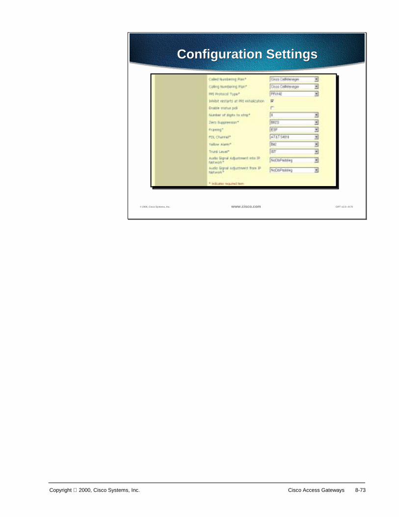
Copyright 2000, Cisco Systems, Inc. Cisco Access Gateways 8-73
© 2000, Cisco Systems, Inc. www.cisco.com CIPT v2.0—8-70
Configuration SettingsConfiguration Settings

8-74 Cisco IP Telephony Copyright 2000, Cisco Systems, Inc.
Field Description Usage Notes
Calling party IE number type unknown
The format for the 'Numbering Plan' in called party directory numbers.
Cisco CallManager sets called DN 'Numbering Plan'. We recommend you do not change the default value unless you have advanced experience with dialing plans, such as NANP or the European dialing plan. You may need to change the default in Europe because Cisco CallManager does not recognize European national dialing patterns. You can also change this setting when connecting to PBXs using routing as a non-national type number.
Use the following definition for each of the variables:
CallManager—The Cisco CallManager sets the directory number type.
International—Use when you are dialing outside the dialing plan of your country.
National—Use when you are dialing within the dialing plan of your country.
Unknown—The dialing plan is unknown.
Called Numbering Plan
The format for the 'Numbering Plan' in called party directory numbers.
Cisco CallManager sets called DN 'Numbering Plan'. We recommend you do not change the default value unless you have advanced experience with dialing plans, such as NANP or the European dialing plan. You may need to change the default in Europe because Cisco CallManager does not recognize European national dialing patterns. You can also change this setting when connecting to PBXs using routing as a non-national type number.
Use the following definition for each of the variables:
CallManager—The Cisco CallManager sets the Numbering Plan in the directory number.
ISDN—Use when you are dialing outside the dialing plan of your country.
National Standard—Use when you are dialing within the dialing plan of your country.
Private—Use when you are dialing within a 'private' network. Unknown—The dialing plan is unknown.
Calling Numbering Plan
The format for the 'Numbering Plan' in calling party directory numbers.
Cisco CallManager sets calling DN 'Numbering Plan'. We recommend you do not change the default value unless you have advanced experience with dialing plans, such as NANP or the European dialing plan. You may need to change the default in Europe because Cisco CallManager does not recognize European national dialing patterns. You can also change this setting when connecting to PBXs using routing as a non-national type number.
Use the following definition for each of the variables:
CallManager—The Cisco CallManager sets the Numbering Plan in the directory number.
ISDN—Use when you are dialing outside the dialing plan of your country.
National Standard—Use when you are dialing within the dialing plan of your country.
Private—Use when you are dialing within a 'private' network. Unknown—The dialing plan is unknown.
PRI Protocol Type
The communications protocol for the span:
4E—AT&T InterExchange carrier
5E8 Custom—Cisco IP Phone (does not conform to national ISDN standards)
5E9 and NI2—AT&T family local exchange switch or carrier
Australian—European ISDN
DMS—MCI family local exchange switch or carrier
ETSI SC—European local exchange carrier
Euro—European ISDN
Determine the switch to which you are connecting and the preferred protocol, as follows:
Nortel Meridian—5E8 Custom
Lucent Definity—4ESS or 5E8
Madge (Teleos) box—5E8 Teleos
Intecom PBX—5E8 Intecom
Alternatively, select the protocol based on the carrier:
MCI—DMS-250
Sprint—DMS-250 or DMS-100
AT&T—4ESS
Inhibit restarts A restart is a message that confirms the Enable or disable When the D-Channel

Copyright 2000, Cisco Systems, Inc. Cisco Access Gateways 8-75
at PRI initialization
status of the ports on a PRI span. If restarts are not sent, they are assumed to be in service.
successfully connects with another PRI's D-Channel it sends restarts when this option is disabled.
Enable status poll
Enable to view the B-channel status in the debug window.
Number of digits to strip
The number of digits to strip on outbound calls, from 0 to 32.
For example, 8889725551234 are dialed, and the number of digits to strip is 3. In this example, 888 are stripped from the outbound number.
Zero Suppression
Determines how the T1 or E1 span electrically codes binary 1's and 0's on the wire (line coding selection).
For a T1, this could be AMI (Alternate Mark Inversion) or B8ZS (Bipolar 8-Zeros Substitution). For an E1, this could be AMI or HDB3.
Framing Determines the multiframe format of the span.
The choices are (for T1).
SF—superframe consisting of 12 frames.
ESF—extended superframe consisting of 24 frames. E1 is always ESF (Extended Superframe, consisting of 16 frames).
FDL Channel Determines what kind, if any, facility data link is supported by the span. The FDL is a maintenance channel that allows remote troubleshooting of link-layer problems, and remote monitoring of performance statistics of the link.
Only relevant on T1 spans. Choices are:
ANSI T.401
AT&T PUB 54016
Yellow Alarm Determines how a remote alarm indication is coded on a T1 span. A yellow alarm indicates that the other end of the link has lost frame synchronization on the signal being transmitted by this end.
Choices include F-bit (out of band signaling; allows 64kbps clear channel bearer capability per B-channel), or bit-2 (in band signaling; robs bit 2 of every channel).
Trunk Level Adjusts the gain of audio entering or leaving the span.
Adjustment to Received
Audio Signal
Specifies the gain or loss applied to the received audio signal relative to the port application type.
Select the gain or loss you want applied to the received audio signal relative to the following port application types:
AnalogCOTrunk—Minus3db
DigitalToAnalogCO—NoDbPadding
AnalogTieTrunk—NoDbPadding
DigitalToDigitalCO—NoDbPadding
ISDNStation—NoDbPadding
ISDN_DigitalTieTrunk—NoDbPadding
ISDNTrunk—NoDbPadding
OnPremisePOTSLine—Plus3db
OffPremisePOTSLine—NoDbPadding
SatelliteAnalogTieTrunk—NoDbPadding
SatelliteDigitalTieTrunk—NoDbPadding
AnalogTollTrunk—Plus3db
Adjustment to Transmitted Audio Signal
Specifies the gain or loss applied to the transmitted audio signal relative to the port application type.
Select the gain or loss you want applied to the transmitted audio signal relative to the following port application types:
AnalogCOTrunk—Minus6db

8-76 Cisco IP Telephony Copyright 2000, Cisco Systems, Inc.
DigitalToAnalogCO—Minus3db
AnalogTieTrunk—NoDbPadding
DigitalToDigitalCO—NoDbPadding
ISDNStation—NoDbPadding
ISDN_DigitalTieTrunk—NoDbPadding
ISDNTrunk—NoDbPadding
OnPremisePOTSLine—Plus3db
OffPremisePOTSLine—Minus3db
SatelliteAnalogTieTrunk—Minus3db
SatelliteDigitalTieTrunk—Minus3db
AnalogTollTrunk—NoDbPadding
D Channel Enable
If enabled for an E1 or T1 PRI, then one of the span B-channels will be appropriated and used to establish a D-channel across the span for Common Channel Signaling (CCS) of calls.
If disabled, then all B-channels on the span will be available for audio calls.
Card Locations
When you set this option, the Device Wizard--Slot Position screen appears. Follow the diagram in the Device Wizard.
Only appears on a DT-24 Gateway.
A slot position refers to the peripheral component interconnect (PCI) card slot into which the digital signal processor (DSP) card is plugged. When adding a new card to the digital access, always add cards from right to left when viewing the gateway from the back. The first (oldest) card should be in the right-most slot (labeled 1 in the Device Wizard), and each subsequent card should be installed in the next available slot position, moving from right to left. If you have existing cards that were not installed in the right-most positions, move the original cards to the right-most slots before adding the new card.

Copyright 2000, Cisco Systems, Inc. Cisco Access Gateways 8-77
Adding an H.323 Gateway
? 2000, Cisco Systems, Inc. www.cisco.com CIPT v2.0? -69
Procedures for Adding anH.323 Gateway
Procedures for Adding anH.323 Gateway
To add the an H.323 gateway, use the following procedure:
1. Open Cisco CallManager.
2. Select Device > Add a New Device. The Add Device screen appears.
3. Select Device Type > Gateway.
4. Select Gateway Type > H.323.
5. Select the Device Protocol. The following device protocols are available:
■ H.225
■ Inter-cluster Trunk
6. Click Next. Enter the appropriate settings as described in the table, H.323 Gateway Configuration Settings, on the following page.

8-78 Cisco IP Telephony Copyright 2000, Cisco Systems, Inc.
Field Description Usage Notes
Device Name Specifies unique name used by CallManager to identify the device.
Description Clarifies purpose of device.
Device Pool Specifies the collection of properties for this device including CallManager Group, Date and Time Setting, Region, and Calling Search Space for auto-registration of devices.
Calling Search Space
Specifies the collection of Route Partitions searched to determine how a dialed number should be routed.
Caller ID DN The pattern you want to use for Caller ID, from 0 to 24 digits.
For example, in North America:
555XXXX = variable Caller ID, where X is equal to an extension number. The CO appends the number with the area code if you do not specify it.
5555000 = Fixed Caller ID. Use when you want the Corporate number to be sent instead of the exact extension from which the call is placed. The CO appends the number with the area code if you do not specify it.
Calling Party Selection
Any outbound call on a gateway can send directory number information. This field determines which directory number is sent.
The following options specify which directory number is sent:
Originator—send the directory number of the calling device.
First Redirect Number—send the directory number of the redirecting device.
Last Redirect Number—send the directory number of the last device to redirect the call.
Presentation Bit Determines whether the central office transmits or blocks caller ID.
Allowed Select if you want the Central Office to send caller ID.
Restricted Select if you do not want the Central Office to send caller ID.
Gatekeeper registration
A Gatekeeper is an H.323 entity on the LAN that provides address translation and controls access to the LAN for connections between H.323-compliant devices such as terminals and gateways. Use only for H.323-compliant gateways. All other devices do not use this box.
If your device is not gatekeeper controlled, select None.
If your device is registered with the Cisco CallManager gatekeeper, select Local.
If your device is registered with a specific remote gatekeeper, select Remote.
Gatekeeper Name
The Domain Name Service (DNS) name or IP address of the H.323 gatekeeper.
Use only for H.323-compliant gateways. All other devices do not use this box. This is an optional box. If Remote is selected as the Gatekeeper Registration, type a Gatekeeper Name (optional).
Media Termination Point Required
Determines whether or not a Media Termination Point is used to implement features that H.323 does not support (such as hold and transfer).
Used for H.323 clients only.
7. Click Insert.

Copyright 2000, Cisco Systems, Inc. Cisco Access Gateways 8-79
Laboratory Exercise: Dial Plan and Cisco Access Gateways

8-80 Cisco IP Telephony Copyright 2000, Cisco Systems, Inc.
Summary This section summarizes the concepts you learned in this chapter.
? 2000, Cisco Systems, Inc. www.cisco.com CIPT v2.0? -70
SummarySummary
• Cisco CallManager 3.0 supports three types ofgateway protocols: skinny, H.323, and MGCP.
• Out-of-band signaling for carrying DTMF tonesacross VoIP provides a solution for codecinduced symptoms.
• IOS gateways support H.323v2, which cansupport supplementary services and eliminatesthe use of software MTP.
Cisco CallManager 3.0 supports three types of gateway protocols:
■ Skinny gateway protocol—used by the digital gateways, including the Cisco Digital IP Telephony Gateway DT-24+ and DE-30+, as well as the Catalyst 6000 Voice Gateway module.
■ H.323—used by the Cisco IOS integrated router gateways to communicate with Cisco CallManager.
■ Media Gateway Control Protocol (MGCP)—used by Cisco CallManager to control the new VG200 standalone analog gateway.
DTMF uses specific pairs of frequencies within the voice band for signaling. Over a 64 kbps pulse code modulation (PCM) voice channel, these signals can be carried without difficulty. However, when using a low bit-rate codec for voice compression, the potential exists for DTMF signal loss or distortion. Using an out-of-band signaling method for carrying DTMF tones across a voice over IP infrastructure provides an elegant solution for these codec-induced symptoms.
The use of H.323v2 in IOS release 12.0(7)T and above (specifically the OpenLogicalChannel, CloseLogicalChannel, and emptyCapabiliySet features) by IOS gateways and CallManager 3.0 eliminates the requirement for MTP to provide supplementary services. Because MTP is no longer needed to terminate the G.711 RTP streams from both the IP phones and the IOS gateway, compressed voice calls (G.723.1 and G.729a) are now supported between IOS gateways and CallManager endpoints.

Copyright 2000, Cisco Systems, Inc. Cisco Access Gateways 8-81
Review Questions Answer the following questions.
? 2000, Cisco Systems, Inc. www.cisco.com CIPT v2.0? -71
Review QuestionsReview Questions
1.What are the three core requirements foran CIPT gateway?
2.Which CIPT gateways support theskinny station signaling protocol?
3.Media gateway control protocol is usedwith which CIPT gateway?
Q1) Every CIPT gateway selection is made by combining common or core requirements with site and implementation specific features. What are the three core requirements for a CIPT gateway?
Q2) Of the CIPT gateways, which gateway models support skinny gateway protocol?
Q3) The Media gateway protocol is supported by Cisco CallManager 3.0. What is the hardware that supports MGCP?
9
Overview This chapter describes Catalyst digital signal processor (DSP) resources, with emphasis on two new Catalyst 4000 and Catalyst 6000 voice modules, and discusses how to provision these resources. These new modules are the WS-X4604-GWY for the Catalyst 4000 and the WS-X6608-T1 (WS-X6608-E1 for countries outside the USA) for the Catalyst 6000. They can perform conferencing and media termination point (MTP) transcoding services in addition to serving as a PSTN gateway.
This chapter includes the following major sections:
■ Objectives
■ Understanding the Catalyst DSP Resources
■ Catalyst 4000 Voice Services
■ Catalyst 6000 Voice Services
■ Catalyst Conferencing Services
■ Catalyst MTP Transcoding Services
■ Installation in Cisco CallManager Administration
■ Summary
■ Review Questions

9-2 Cisco IP Telephony Copyright 2000, Cisco Systems, Inc.
Objectives This section lists the chapter objectives.
? 2000, Cisco Systems, Inc. www.cisco.com CIPT v2.0? -3
ObjectivesObjectives
Upon completion of this chapter, you will beable to perform the following tasks:• Identify and describe conferencing design
details• Identify and describe MTP/transcoding design
details• Install and configure conferencing and
MTP/transcoding resources in the CiscoCallManager administration
• Invoke DSP resources on a phone call
Upon completion of this chapter, you will be able to perform the following tasks:
■ Given a list of Cisco IP telephony design details, identify and describe the design details related to hardware conferencing.
■ Given a list of Cisco IP telephony design details, identify and describe the design details related to hardware MTP/transcoding.
■ Given a Catalyst 6000 with the WS-X6608-T1 or WS-X6608-E1 installed, install and configure conferencing and MTP/transcoding resources in the Cisco CallManager administration.
■ Given a Cisco IP telephony network and DSP resources installed and configured, invoke the DSP resources (conferencing or MTP/transcoding) on a phone call.
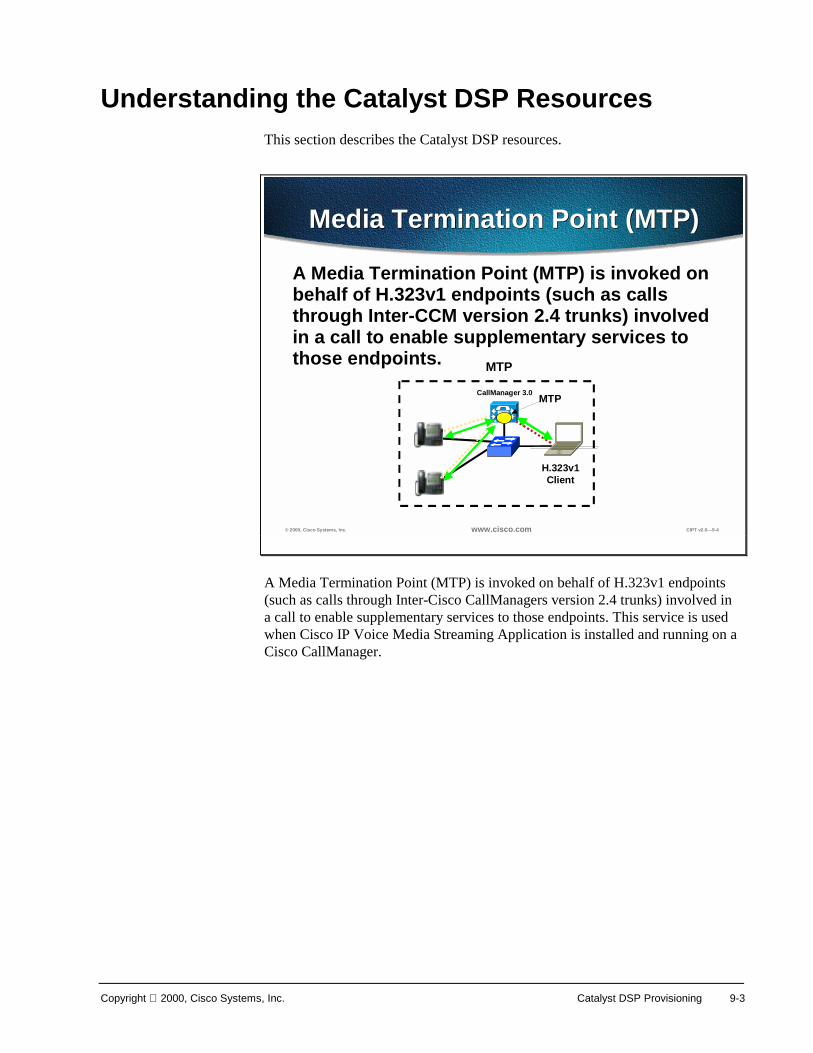
Copyright 2000, Cisco Systems, Inc. Catalyst DSP Provisioning 9-3
Understanding the Catalyst DSP Resources This section describes the Catalyst DSP resources.
© 2000, Cisco Systems, Inc. www.cisco.com CIPT v2.0—9-4
Media Termination Point (MTP)Media Termination Point (MTP)
A Media Termination Point (MTP) is invoked on behalf of H.323v1 endpoints (such as calls through Inter-CCM version 2.4 trunks) involved in a call to enable supplementary services to those endpoints.
H.323v1Client
CallManager 3.0 MTP
MTP
A Media Termination Point (MTP) is invoked on behalf of H.323v1 endpoints (such as calls through Inter-Cisco CallManagers version 2.4 trunks) involved in a call to enable supplementary services to those endpoints. This service is used when Cisco IP Voice Media Streaming Application is installed and running on a Cisco CallManager.

9-4 Cisco IP Telephony Copyright 2000, Cisco Systems, Inc.
© 2000, Cisco Systems, Inc. www.cisco.com CIPT v2.0—9-5
TranscodingTranscoding
A Transcoder is a device that takes the output stream of one CODEC and Transcodes(converts) it from one compression type to another compression type. Specifically, G.723.1 or G.729a can be converted to G.711 and vice-versa.
IOS Gatekeeper
V VRouter/GW Router/GW
Call ManagerCluster
Call ManagerCluster
IP WAN
uOneGateserver
uOneGateserver
Transcoding
A transcoder is a device that takes the output stream of one CODEC and transcodes (converts) it from one compression type to another compression type. Specifically, G.723.1 or G.729a can be converted to G.711 and vice versa. As of now this hardware resource is available on the Catalyst 6000 T1/E1 module.

Copyright 2000, Cisco Systems, Inc. Catalyst DSP Provisioning 9-5
© 2000, Cisco Systems, Inc. www.cisco.com CIPT v2.0—9-6
ConferencingConferencing
• Ad Hoc– User presses “conf” button; 1st caller put on Hold; gets dial-
tone and dials a second user; presses “conf” again and all users are now connected on the conference bridge
• Meet-Me– Conference Controller presses “Meet-Me” button; gets dial-
tone and dials conf call number; all conf call attendees calls conf call number
VRouter/GW
CallManagerCluster
uOneGateserver
Conferencing
Conferencing is the ability to speak with three or more persons on a phone call. There are two types of conferencing, Ad Hoc and Meet-Me. An Ad Hoc conference is when a user is on a call with another person and then wants to add someone else on to the call. A Meet-Me conference is a phone conference that individuals or groups of people use a phone device to call into one conference number for a phone conference.

9-6 Cisco IP Telephony Copyright 2000, Cisco Systems, Inc.
? 2000, Cisco Systems, Inc. www.cisco.com CIPT v2.0? -4
DSP Resource Modules for the4000 and 6000
DSP Resource Modules for the4000 and 6000
Catalyst 4000• WS-X4604-GWY
Catalyst 6000• WS-X6608-T1/WS-X6608-E1
The DSP resources on the new Catalyst 4000 and 6000 gateway modules essentially provide hardware support for IP telephony features offered by the Cisco CallManager. These features are hardware-enabled voice conferencing, hardware-based MTP support for supplementary services, and MTP transcoding services.
Catalyst enabled conferencing supports voice conferences in hardware. DSPs convert G.711 voice sessions into TDM streams, which can then be mixed into a conference call by another DSP. The Catalyst MTP service can either act like the original software MTP resource or as a transcoding MTP resource.
An MTP service provides supplementary services such as hold, transfer, and conferencing when using gateways that do not support the H.323v2 feature of OpenLogicalChannel and CloseLogicalChannel with the EmptyCapabilitiesSet. This is available as a software feature that can run on the CallManager or on a separate NT server. When running in software on a CallManager, 24 MTP sessions are supported. When running on a separate NT server, up to 48 MTP sessions are supported. The new Catalyst gateway modules can support this same functionality, but provide the service in hardware.
MTP transcoding is in effect an IP-to-IP voice gateway service. A transcoding node can convert a G.711 voice stream into a low bit-rate (LBR) compressed voice stream, such as G.729a. This is critical for enabling applications such as integrated voice response (IVR), uOne messaging, and conference calls over slow speed IP WANs. MTP transcoding is only supported on the Catalyst voice gateways.
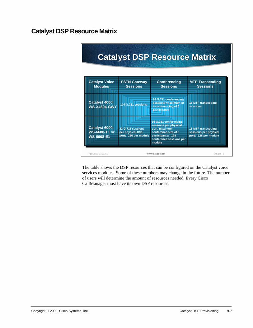
Copyright 2000, Cisco Systems, Inc. Catalyst DSP Provisioning 9-7
Catalyst DSP Resource Matrix
? 2000, Cisco Systems, Inc. www.cisco.com CIPT v2.0? -5
Catalyst DSP Resource MatrixCatalyst DSP Resource Matrix
Catalyst VoiceModules
PSTN GatewaySessions
ConferencingSessions
MTP TranscodingSessions
Catalyst 4000WS-X4604-GWY
Catalyst 6000WS-6608-T1 orWS-6608-E1
104 G.711 sessions
32 G.711 sessionsper physical DS1port; 256 per module
24 G.711 conferencingsessions?maximum of4 conferencing of 6participants
16 G.711 conferencingsessions per physicalport, maximumconference size of 6participants; 128conference sessions permodule
16 MTP transcodingsessions
16 MTP transcodingsessions per physicalport; 128 per module
The table shows the DSP resources that can be configured on the Catalyst voice services modules. Some of these numbers may change in the future. The number of users will determine the amount of resources needed. Every Cisco CallManager must have its own DSP resources.
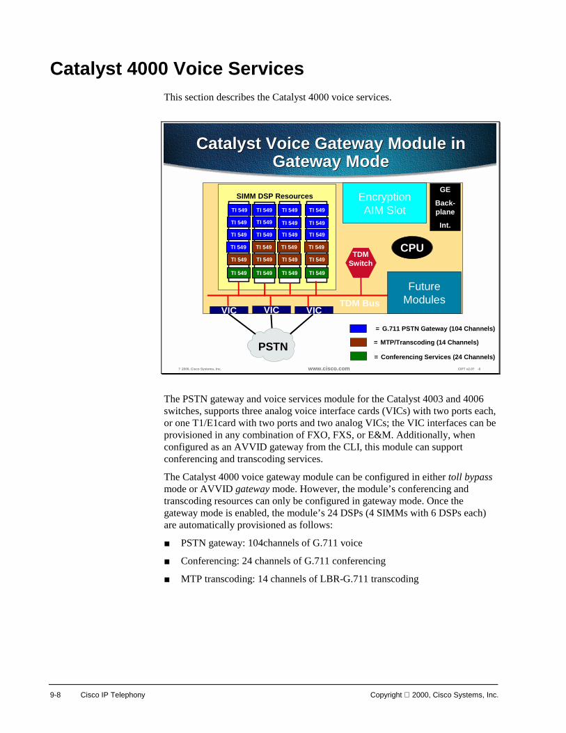
9-8 Cisco IP Telephony Copyright 2000, Cisco Systems, Inc.
Catalyst 4000 Voice Services This section describes the Catalyst 4000 voice services.
? 2000, Cisco Systems, Inc. www.cisco.com CIPT v2.0? -6
Catalyst Voice Gateway Module inGateway Mode
Catalyst Voice Gateway Module inGateway Mode
VIC
PSTN
VIC VICTDM Bus
FutureModules
EncryptionAIM Slot
SIMM DSP Resources
TI 549
TI 549
TI 549
TI 549
TI 549
TI 549
TI 549
TI 549
TI 549
TI 549
TI 549
TI 549
TI 549
TI 549
TI 549
TI 549
TI 549
TI 549
TI 549
TI 549
TI 549
TI 549
TI 549
TI 549 CPU
GE
Back-plane
Int.
= G.711 PSTN Gateway (104 Channels)
= MTP/Transcoding (14 Channels)
= Conferencing Services (24 Channels)
TDMSwitch
The PSTN gateway and voice services module for the Catalyst 4003 and 4006 switches, supports three analog voice interface cards (VICs) with two ports each, or one T1/E1card with two ports and two analog VICs; the VIC interfaces can be provisioned in any combination of FXO, FXS, or E&M. Additionally, when configured as an AVVID gateway from the CLI, this module can support conferencing and transcoding services.
The Catalyst 4000 voice gateway module can be configured in either toll bypass mode or AVVID gateway mode. However, the module’s conferencing and transcoding resources can only be configured in gateway mode. Once the gateway mode is enabled, the module’s 24 DSPs (4 SIMMs with 6 DSPs each) are automatically provisioned as follows:
■ PSTN gateway: 104channels of G.711 voice
■ Conferencing: 24 channels of G.711 conferencing
■ MTP transcoding: 14 channels of LBR-G.711 transcoding

Copyright 2000, Cisco Systems, Inc. Catalyst DSP Provisioning 9-9
? 2000, Cisco Systems, Inc. www.cisco.com CIPT v2.0? -7
Configuration CommandsConfiguration Commands
voicecard mtp
mtp-address <IP>
manager-address [<IP1>|<DNS1>]
manager-address [<IP2>|<DNS2>]
manager-address [<IP3>|<DNS3>]
voicecard conference
conference-address <IP>
manager-address [<IP1>|<DNS1>]
manager-address [<IP2>|<DNS2>]
manager-address [<IP3>|<DNS3>]
voicecard mtp
mtp-address <IP>
manager-address [<IP1>|<DNS1>]
manager-address [<IP2>|<DNS2>]
manager-address [<IP3>|<DNS3>]
voicecard conference
conference-address <IP>
manager-address [<IP1>|<DNS1>]
manager-address [<IP2>|<DNS2>]
manager-address [<IP3>|<DNS3>]
Gateway mode is the default configuration. The conferencing-to-transcoding ratios can be changed from the CLI, as shown by the configuration commands. By changing the number of transcoding sessions to 14, instead of 16, an additional 8-conferencing session can be enabled.
The following configuration points should be noted:
■ The WS-X4604-GWY uses an IOS interface for initial device configuration. For all PSTN gateway functions, the Catalyst 4000 module uses H.323v2 and is configured identically to an IOS gateway. From the CallManager configuration screen, simply add the Catalyst 4000 gateway as an H.323 gateway.
■ For all voice services features, such as hardware-based conferencing or MTP transcoding, the module relies on the Skinny Station Protocol for CallManager interaction. Therefore, once the above CLI commands are entered for defining conferencing and transcoding functions, all additional configurations for these voice features take place on the CallManager.
■ Each service on the module, whether PSTN gateway, conferencing, or MTP transcoding services, requires an IP address. These can be the same IP addresses or different ones for redundancy and management.
■ A prioritized set of CallManagers can be defined for both the conferencing services and MTP transcoding services.
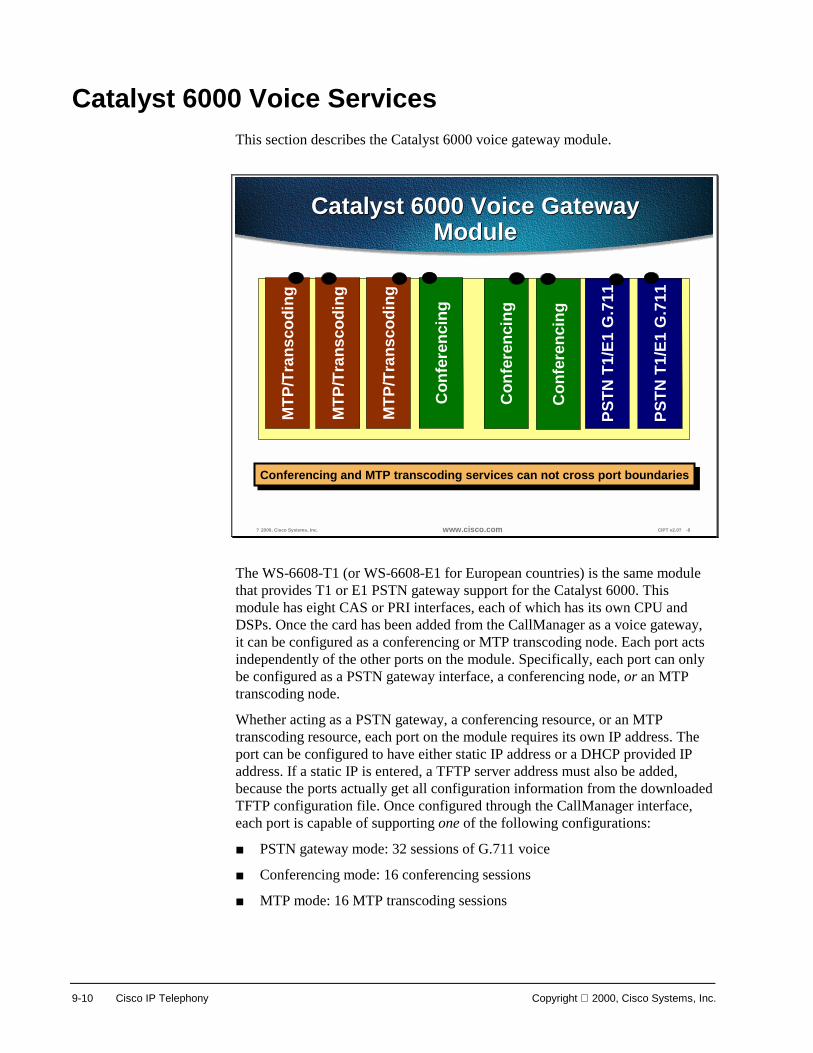
9-10 Cisco IP Telephony Copyright 2000, Cisco Systems, Inc.
Catalyst 6000 Voice Services This section describes the Catalyst 6000 voice gateway module.
? 2000, Cisco Systems, Inc. www.cisco.com CIPT v2.0? -8
Catalyst 6000 Voice GatewayModule
Catalyst 6000 Voice GatewayModule
PSTN
T1/
E1 G
.711
PSTN
T1/
E1 G
.711
MTP
/Tra
nsco
ding
MTP
/Tra
nsco
ding
MTP
/Tra
nsco
ding
Con
fere
ncin
g
Con
fere
ncin
g
Con
fere
ncin
g
Conferencing and MTP transcoding services can not cross port boundariesConferencing and MTP transcoding services can not cross port boundaries
The WS-6608-T1 (or WS-6608-E1 for European countries) is the same module that provides T1 or E1 PSTN gateway support for the Catalyst 6000. This module has eight CAS or PRI interfaces, each of which has its own CPU and DSPs. Once the card has been added from the CallManager as a voice gateway, it can be configured as a conferencing or MTP transcoding node. Each port acts independently of the other ports on the module. Specifically, each port can only be configured as a PSTN gateway interface, a conferencing node, or an MTP transcoding node.
Whether acting as a PSTN gateway, a conferencing resource, or an MTP transcoding resource, each port on the module requires its own IP address. The port can be configured to have either static IP address or a DHCP provided IP address. If a static IP is entered, a TFTP server address must also be added, because the ports actually get all configuration information from the downloaded TFTP configuration file. Once configured through the CallManager interface, each port is capable of supporting one of the following configurations:
■ PSTN gateway mode: 32 sessions of G.711 voice
■ Conferencing mode: 16 conferencing sessions
■ MTP mode: 16 MTP transcoding sessions
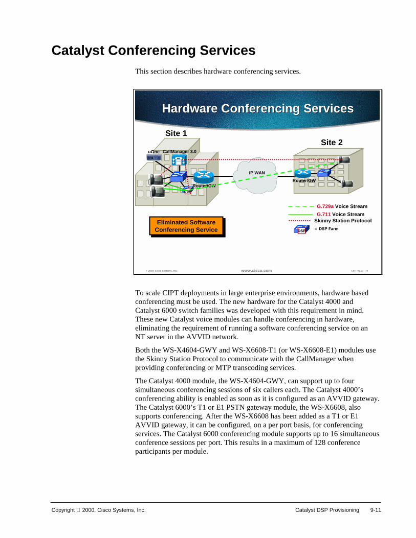
Copyright 2000, Cisco Systems, Inc. Catalyst DSP Provisioning 9-11
Catalyst Conferencing Services This section describes hardware conferencing services.
? 2000, Cisco Systems, Inc. www.cisco.com CIPT v2.0? -9
Hardware Conferencing ServicesHardware Conferencing Services
DSPRouter/GW
CallManager 3.0
IP WAN
uOne
Router/GW
Skinny Station Protocol G.711 Voice Stream G.729a Voice Stream
Site 1Site 2
DSP = DSP FarmEliminated Software
Conferencing ServiceEliminated Software
Conferencing Service
To scale CIPT deployments in large enterprise environments, hardware based conferencing must be used. The new hardware for the Catalyst 4000 and Catalyst 6000 switch families was developed with this requirement in mind. These new Catalyst voice modules can handle conferencing in hardware, eliminating the requirement of running a software conferencing service on an NT server in the AVVID network.
Both the WS-X4604-GWY and WS-X6608-T1 (or WS-X6608-E1) modules use the Skinny Station Protocol to communicate with the CallManager when providing conferencing or MTP transcoding services.
The Catalyst 4000 module, the WS-X4604-GWY, can support up to four simultaneous conferencing sessions of six callers each. The Catalyst 4000’s conferencing ability is enabled as soon as it is configured as an AVVID gateway. The Catalyst 6000’s T1 or E1 PSTN gateway module, the WS-X6608, also supports conferencing. After the WS-X6608 has been added as a T1 or E1 AVVID gateway, it can be configured, on a per port basis, for conferencing services. The Catalyst 6000 conferencing module supports up to 16 simultaneous conference sessions per port. This results in a maximum of 128 conference participants per module.

9-12 Cisco IP Telephony Copyright 2000, Cisco Systems, Inc.
Conferencing Design Details
? 2000, Cisco Systems, Inc. www.cisco.com CIPT v2.0? -10
Conferencing Design DetailsConferencing Design Details
• Max number of 16 participants per conferencecall
• WS-X4604-GWY supports 24 conferencingsessions per module
• WS-X6608-T1 or WS-X6608-E1 supports 16conferencing sessions per physical port, 128per module
• All conference calls are G.711 only• MTP transcoding can be used to convert
G.729a or G.723.1 to G.711 for conference calls• CallManagers cannot share DSP resources
The following points summarize the design capabilities and requirements of the new Catalyst voice modules:
■ Maximum of 16 participants per conference call.
■ WS-X4604-GWY supports 24 conferencing sessions per module.
■ WS-X6608-T1 or WS-X6608-E1 supports 16 conferencing sessions per physical port, 128 per module.
■ All conference calls are G.711 only.
■ MTP transcoding can be used to convert G.729a or G.723.1 to G.711 for conference calls.
■ Each CallManager must have its own conference and MTP transcoding resources, because the DSP resources can only register with one CallManager at a time. CallManagers cannot share DSP resources.
The following additional points should be noted:
■ When provisioning an enterprise with conference ports, it is vital to know how many callers will be attempting to join the conference calls from a compressed CallManager region. Once the number of compressed callers is identified, then the MTP transcoding resources can be accurately provisioned.
■ Each configured CallManager should have its own conferencing module associated with it, because conference bridges cannot register with more

Copyright 2000, Cisco Systems, Inc. Catalyst DSP Provisioning 9-13
than one CallManager at a time, and CallManagers cannot share DSP resources.

9-14 Cisco IP Telephony Copyright 2000, Cisco Systems, Inc.
Conferencing Caveats
? 2000, Cisco Systems, Inc. www.cisco.com CIPT v2.0? -11
Conferencing CaveatsConferencing Caveats
• Catalyst conferencing services support G.711connections only.
• On the Catalyst 6000, conferencing servicescannot cross port boundaries.
• Each CallManager must have its ownconferencing resource configured.
The following caveats apply to Catalyst conferencing services:
■ Catalyst conferencing services support G.711 connections only.
■ On the Catalyst 6000, conferencing services cannot cross-port boundaries.
■ Each CallManager must have its own conferencing resource configured.
The conferencing resource can support only G.711, however, a compressed (G.723 or G.729) call can join the conference because the conferencing resource will transcode that call to G.711 to participate in the conference.
Note One user requires one session or stream to connect into a conference, so if a device registers 16 sessions or streams it is saying that it can support 16 parties connected to conferences on that device.

Copyright 2000, Cisco Systems, Inc. Catalyst DSP Provisioning 9-15
Catalyst MTP Transcoding Services This section describes the Catalyst MTP transcoding services.
? 2000, Cisco Systems, Inc. www.cisco.com CIPT v2.0? -12
Router/GW
IP WAN
MTPRouter/GW
CallManager 3.0uOne
Site 1 Site 2
Catalyst MTP TranscodingServices
Catalyst MTP TranscodingServices
Uncompressed Voice(G.711)
in the campus
Uncompressed Voice(G.711)
in the campus
Voice Compression(G.723.1 or G.729)
between sites
Voice Compression(G.723.1 or G.729)
between sites
Hardware basedMTP transcoding
services
Hardware basedMTP transcoding
services
Introducing the WAN into a CIPT implementation forces the issue of voice compression. In the previous designs, all campus-oriented voice was uncompressed (G.711) to provide the highest quality while incurring the fewest complications. Once a WAN enabled CIPT network is deployed, voice compression between sites is the recommended design choice. This calls into question how WAN users use the conferencing services or IP enabled applications, such as the uOne Messaging Server, which only support G.711 voice connections. The solution is to use hardware-based MTP transcoding services to convert the compressed voice streams into G.711.

9-16 Cisco IP Telephony Copyright 2000, Cisco Systems, Inc.
MTP Transcoding Design Details
? 2000, Cisco Systems, Inc. www.cisco.com CIPT v2.0? -13
MTP Transcoding DesignDetails
MTP Transcoding DesignDetails
• Provision MTP transcoding resourcesappropriately
• WS-X4604-GWY supports 14 transcodingmediastreams per module
• WS-X6608-T1/E1 supports 16 transcodingmediastreams per physical port, 128 permodule
• Transcoding is low bit-rate to high bit-rate, orvice versa
• Each CallManager must have its own MTPtranscoding resources
• Own jitter buffer of 20 to 40 ms
Each Cisco CallManager should have its own transcoding resource. Transcoding resources can transcode from low bit-rate to high bit-rate and vice versa. For example a G.729 call can be transcoded to a G.711, but may not be transcoded to G.723. This is very helpful when deploying the CIPT solution across the IP WAN. A case where a caller is across the IP WAN and needs to access their voice mail (uOne Gateserver) that only allows G.711 codec. The transcoding resource can take a G.729 codec call coming in across the WAN and convert it to G.711 codec so the call can access their voice mail. In the transcoding resource it produces its own jitter buffer of 20 to 40 ms.

Copyright 2000, Cisco Systems, Inc. Catalyst DSP Provisioning 9-17
IP-to-IP Packet Transcoding and Voice Compression
? 2000, Cisco Systems, Inc. www.cisco.com CIPT v2.0? -14
IP-to-IP Packet GatewayTranscoding
IP-to-IP Packet GatewayTranscoding
Router/GW
CallManager 3.0
IP WAN
uOne
Router/GW
Skinny Station Protocol G.711 Voice Stream G.729a Voice Stream
Site 1Site 2
DSP = DSP FarmWAN withCentralized Call
Processing
WAN withCentralized Call
Processing
DSP
Voice compression between IP phones is easily configured through the use of regions and locations in CallManager 3.0. However, both the Catalyst conferencing services and the uOne messaging software currently only support G.711, or uncompressed, connections. For these situations, MTP transcoding or packet-to-packet gateway functionality has been added to two of the new modules for the Catalyst 4000 and Catalyst 6000.
A packet-to-packet gateway is a device with DSPs that has the job of transcoding between voice streams using different compression algorithms. That is, when a user on an IP phone at a remote location calls a user located at the central location, the CallManager instructs the remote IP phone to use compressed voice, or G.729a, only for the WAN call.
However, if the called user at the central site is unavailable, the call rolls to the uOne messaging system, which supports G.711 only. In this case, a packet-to-packet gateway transcodes the G.729a voice stream to G.711 to leave a message with the uOne Messaging Server.

9-18 Cisco IP Telephony Copyright 2000, Cisco Systems, Inc.
Voice Compression, IP-to-IP Packet Transcoding, and Conferencing
? 2000, Cisco Systems, Inc. www.cisco.com CIPT v2.0? -15
IP-to-IP Packet GatewayTranscoding
IP-to-IP Packet GatewayTranscoding
Router/GW Router/GW
CallManager 3.0CallManager 3.0
IP WAN
uOne uOne
Skinny Station ProtocolH.323v2
G.711 Voice Stream G.729a Voice Stream
Site 1 Site 2
= DSP Farm
WAN withDistributed Call
Processing
WAN withDistributed Call
Processing
DSPDSP
DSP
Connecting sites across an IP WAN for conference calls presents a complex scenario. The H.323v2 signaling is the inter-cluster communication between Cisco CallManagers during the call set up to notify the caller that they need a DSP resource for their call. In this scenario, the Catalyst modules must perform the conferencing service as well as the IP-to-IP transcoding service to uncompress the WAN IP voice connection. In the illustration above, a remote user joins a conference call at the three-participant conference call uses 11 DSP channels: three conferencing channels, six G.711 channels, and two transcoding channels.
The following is the breakdown:
■ One DSP channel to convert the IP WAN G.729a voice call into G.711
■ Three G.711 DSP channels to convert the G.711 stream into TDM for the conferencing DSP
■ Three channels from the conferencing DSP to mix the three callers together
■ Three G.711 channels to convert the TDM voice back into G.711
■ One DSP channel to convert G.711 into G.729a for the IP WAN caller
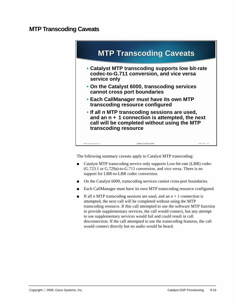
Copyright 2000, Cisco Systems, Inc. Catalyst DSP Provisioning 9-19
MTP Transcoding Caveats
? 2000, Cisco Systems, Inc. www.cisco.com CIPT v2.0? -16
MTP Transcoding CaveatsMTP Transcoding Caveats
• Catalyst MTP transcoding supports low bit-ratecodec-to-G.711 conversion, and vice versaservice only
• On the Catalyst 6000, transcoding servicescannot cross port boundaries
• Each CallManager must have its own MTPtranscoding resource configured
• If all n MTP transcoding sessions are used,and an n + 1 connection is attempted, the nextcall will be completed without using the MTPtranscoding resource
The following summary caveats apply to Catalyst MTP transcoding:
■ Catalyst MTP transcoding service only supports Low-bit-rate (LBR) codec (G.723.1 or G.729a)-to-G.711 conversion, and vice versa. There is no support for LBR-to-LBR codec conversion.
■ On the Catalyst 6000, transcoding services cannot cross-port boundaries.
■ Each CallManager must have its own MTP transcoding resource configured.
■ If all n MTP transcoding sessions are used, and an n + 1 connection is attempted, the next call will be completed without using the MTP transcoding resource. If this call attempted to use the software MTP function to provide supplementary services, the call would connect, but any attempt to use supplementary services would fail and could result in call disconnection. If the call attempted to use the transcoding features, the call would connect directly but no audio would be heard.
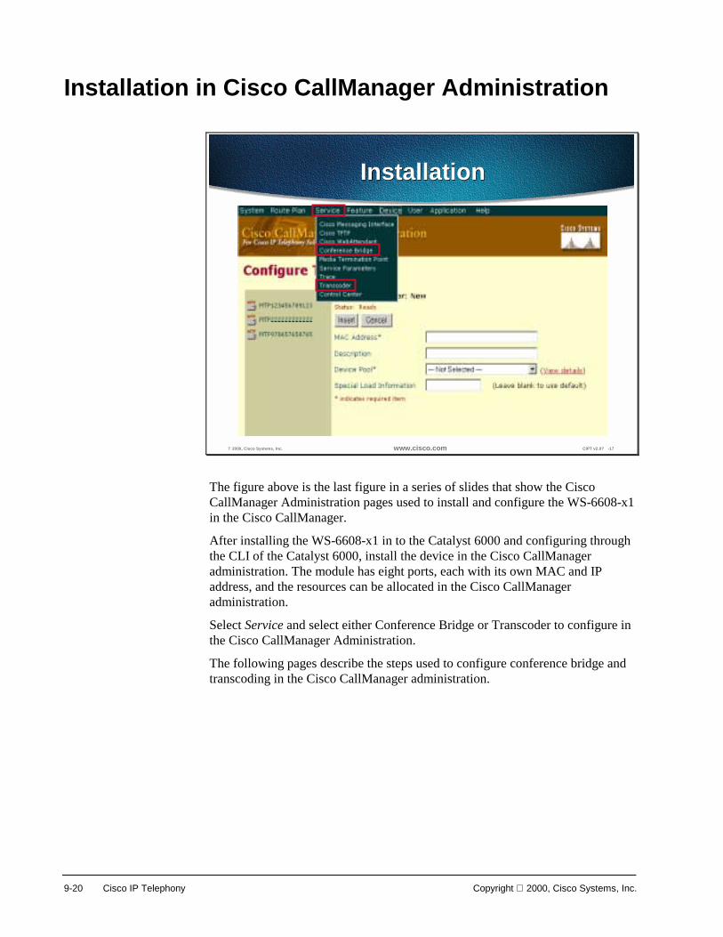
9-20 Cisco IP Telephony Copyright 2000, Cisco Systems, Inc.
Installation in Cisco CallManager Administration
? 2000, Cisco Systems, Inc. www.cisco.com CIPT v2.0? -17
InstallationInstallation
The figure above is the last figure in a series of slides that show the Cisco CallManager Administration pages used to install and configure the WS-6608-x1 in the Cisco CallManager.
After installing the WS-6608-x1 in to the Catalyst 6000 and configuring through the CLI of the Catalyst 6000, install the device in the Cisco CallManager administration. The module has eight ports, each with its own MAC and IP address, and the resources can be allocated in the Cisco CallManager administration.
Select Service and select either Conference Bridge or Transcoder to configure in the Cisco CallManager Administration.
The following pages describe the steps used to configure conference bridge and transcoding in the Cisco CallManager administration.

Copyright 2000, Cisco Systems, Inc. Catalyst DSP Provisioning 9-21
Conference Bridge
? 2000, Cisco Systems, Inc. www.cisco.com CIPT v2.0? -18
Conference BridgeConfiguration
Conference BridgeConfiguration
Initial Conference BridgeConfiguration Page
Initial Conference BridgeConfiguration Page
Port MACAddress
Port MACAddress
ab? auto inserts
FB<MAC Address>�
ab? auto inserts
FB<MAC Address>�
SelectDevice Pool
SelectDevice Pool
Option: ModifyDescription
Option: ModifyDescription
MustReset Device
MustReset Device
The figure above is the last slide in a series of slides to demonstrate the Cisco CallManager Administration pages used to install and configure Conference Bridge resources in the Cisco CallManager.
Servers and device pools must be configured before proceeding.
The procedure is as follows:
1. Open Cisco CallManager Administration.
2. Click Service > Conference Bridge.
3. Select Hardware in the Model Type field.
4. Enter a MAC address (must be at least 12 characters) in the MAC address field.
5. The Device Description field is automatically generated from the MAC address you provide.
6. Enter any special load information into the Special Load Information field, or leave blank to use default.
7. Select a device pool from the drop-down menu or choose Default, in the Device Pool field.
8. Click Insert. A message displays stating that the Conference Bridge device must be reset in order for the changes to take effect.
9. Click OK. The page refreshes and displays the conference device you just added. The device should appear in the list on the left side of the page.

9-22 Cisco IP Telephony Copyright 2000, Cisco Systems, Inc.
10. Click Reset Device and follow the instructions in the Reset Device dialog box.

Copyright 2000, Cisco Systems, Inc. Catalyst DSP Provisioning 9-23
? 2000, Cisco Systems, Inc. www.cisco.com CIPT v2.0? -19
Conference Bridge ParametersConference Bridge Parameters
Defaults Numberof Users
Defaults Numberof Users
Servers, Device pools, Cisco CallManager, and Parameters must be configured before proceeding with the steps.
The procedure is as follows:
1. Open Cisco CallManager Administration.
2. Click Service > Conference Bridge.
3. Click Conference Bridge Parameters from either the top right-hand corner or the bottom right-hand corner of the page.
4. The page refreshes and the Conference Bridge Parameters page appears.
5. Select a device pool from the drop-down menu or choose Default. The Cisco CallManagers in this device pool appear in the box to the left of the page.
6. Highlight the Cisco CallManager on which you want to update the conference parameters. The maximum number of users configured for both an Ad-Hoc conference and a Meet-Me conference using Unicast appear in the fields to the right of the page.
7. Change the maximum number of users accordingly and click Update.
Note You must reset each conference bridge device after making updates for the changes to take affect. To do this, click Conference Bridge Configuration and select the Conference Bridge device you want to reset. Next, click Reset Device and follow the instructions in the Reset Device dialog box. Changes will only take place when there are no active calls. When you click Restart, the changes are made immediately.
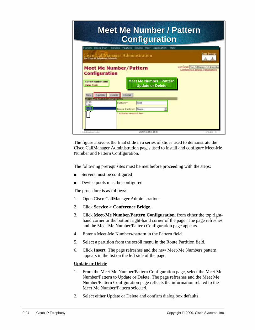
9-24 Cisco IP Telephony Copyright 2000, Cisco Systems, Inc.
? 2000, Cisco Systems, Inc. www.cisco.com CIPT v2.0? -20
Meet Me Number / PatternConfiguration
Meet Me Number / PatternConfiguration
Enter Patternand Select
Route Partition
Enter Patternand Select
Route PartitionConfirmation
DisplayedConfirmation
Displayed
Select Meet Me Numberto Update and Delete
Select Meet Me Numberto Update and Delete
Meet Me Number / PatternUpdate or Delete
Meet Me Number / PatternUpdate or Delete
The figure above is the final slide in a series of slides used to demonstrate the Cisco CallManager Administration pages used to install and configure Meet-Me Number and Pattern Configuration.
The following prerequisites must be met before proceeding with the steps:
■ Servers must be configured
■ Device pools must be configured
The procedure is as follows:
1. Open Cisco CallManager Administration.
2. Click Service > Conference Bridge.
3. Click Meet-Me Number/Pattern Configuration, from either the top right-hand corner or the bottom right-hand corner of the page. The page refreshes and the Meet-Me Number/Pattern Configuration page appears.
4. Enter a Meet-Me Numbers/pattern in the Pattern field.
5. Select a partition from the scroll menu in the Route Partition field.
6. Click Insert. The page refreshes and the new Meet-Me Numbers pattern appears in the list on the left side of the page.
Update or Delete
1. From the Meet Me Number/Pattern Configuration page, select the Meet Me Number/Pattern to Update or Delete. The page refreshes and the Meet Me Number/Pattern Configuration page reflects the information related to the Meet Me Number/Pattern selected.
2. Select either Update or Delete and confirm dialog box defaults.

Copyright 2000, Cisco Systems, Inc. Catalyst DSP Provisioning 9-25

9-26 Cisco IP Telephony Copyright 2000, Cisco Systems, Inc.
Transcoding
? 2000, Cisco Systems, Inc. www.cisco.com CIPT v2.0? -21
Transcoder ConfigurationTranscoder Configuration
Port MACAddress
Port MACAddress
ab? auto inserts
TP<MAC
Address>�
ab? auto inserts
TP<MAC
Address>�
SelectDevice Pool
SelectDevice Pool
ModifyDescription
ModifyDescription
The figure above is the final slide in a series of slides used to demonstrate the Cisco CallManager Administration pages used to install and configure a Transcoding resource in Cisco CallManager.
To configure the transcoder:
1. Open Cisco CallManager Administration.
2. Click Service > Transcoder.
3. Enter a MAC address (must be at least 12 characters) in the MAC Address field. Description field is automatically generated from the MAC address.
4. Enter any special load information into the Special Load Information field, or leave blank to use default.
5. Select a device pool from the drop-down menu or choose Default in the Device Pool field.
6. Click Insert. The page refreshes showing specific information, including the status, for the transcoder you just configured. The transcoder should now be in the list on the left side of the page.

Copyright 2000, Cisco Systems, Inc. Catalyst DSP Provisioning 9-27
Update, Delete or Reset After selecting a transcoder resource from the left of the Configure Transcoder page, select one of the following:
■ Update to update the transcoder information in the Cisco CallManager.
■ Delete to delete the transcoder resource from the Cisco CallManager.
■ Reset to restart or reset the transcoder resource.

9-28 Cisco IP Telephony Copyright 2000, Cisco Systems, Inc.
Summary This section summarizes the concepts you learned in this chapter.
? 2000, Cisco Systems, Inc. www.cisco.com CIPT v2.0? -22
SummarySummary
• The WS-X6608-T1/E1 module can have itsports configured as conferencing ortranscoding resources.
• Only low bit-rate to high bit-ratetranscoding (and vice versa) is supported.
• The conferencing resource will transcodelow bit-rate calls to high bit-rate.
The WS-X6608-T1/E1 module can be configured as a DSP resource. Each port on the module can be configured as different resources. For example, Port 1-2 could be left as T1/E1 resources and ports 3-5 could be transcoding resources and ports 6-8 could be conferencing resources. Each port has its own MAC address and has to be configured from the Catalyst CLI and in the Cisco CallManager.
The transcoding resource can only transcode low bit-rate (G.723 or G.729) to high bit-rate (G.711) and vice versa.
When a call comes in from the IP WAN using low bit-rate (G.723 or G.729) to be in a conference, the conferencing resource transcodes that call because the conferencing resource only supports G.711 codec for conferencing.

Copyright 2000, Cisco Systems, Inc. Catalyst DSP Provisioning 9-29
Review Questions Answer the following questions.
? 2000, Cisco Systems, Inc. www.cisco.com CIPT v2.0? -23
Review QuestionsReview Questions
1. Can DSP resources be shared among CiscoCallManagers in a cluster?
2. What codec transcoding does thetranscoding resource support?
3. Can a G.729a codec join a conference withoutusing a transcoding resource?
Q1) Digital Signaling Processor (DSP) resources provide transcoding and conferencing resources. Can DSP resources be shared among Cisco CallManagers in the same cluster?
Q2) The transcoding resource supports G.711, G.729 and G.723. What codecs can the transcoding resource transcode to and from?
Q3) When a caller across the IP WAN uses G.729 across the IP WAN to join a conference, can that caller join the conference without a transcoding resource?

9-30 Cisco IP Telephony Copyright 2000, Cisco Systems, Inc.
10
Cisco IP Phones
Overview Cisco IP phones are full-featured telephones that can be plugged directly into your IP network. In this section, the following topics are discussed:
■ Objectives
■ Understanding Cisco IP Phones
■ Configuring Cisco IP Phones and Features
■ Trace Basic Call Processing
■ Summary
■ Review Questions
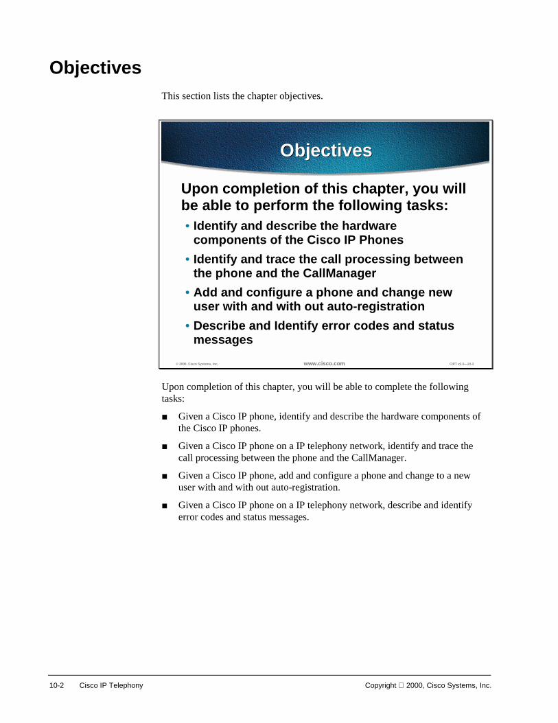
10-2 Cisco IP Telephony Copyright 2000, Cisco Systems, Inc.
Objectives This section lists the chapter objectives.
© 2000, Cisco Systems, Inc. www.cisco.com CIPT v2.0—10-3
ObjectivesObjectives
Upon completion of this chapter, you willbe able to perform the following tasks:• Identify and describe the hardware
components of the Cisco IP Phones• Identify and trace the call processing between
the phone and the CallManager• Add and configure a phone and change new
user with and with out auto-registration• Describe and Identify error codes and status
messages
Upon completion of this chapter, you will be able to complete the following tasks:
■ Given a Cisco IP phone, identify and describe the hardware components of the Cisco IP phones.
■ Given a Cisco IP phone on a IP telephony network, identify and trace the call processing between the phone and the CallManager.
■ Given a Cisco IP phone, add and configure a phone and change to a new user with and with out auto-registration.
■ Given a Cisco IP phone on a IP telephony network, describe and identify error codes and status messages.

Copyright 2000, Cisco Systems, Inc. Cisco IP Phones 10-3
Understanding Cisco IP Phones The Cisco IP phones enable communications using voice over a data network. To do this, the Cisco IP phones depend upon and interact with several other key IP telephony components, including Cisco CallManager and telephony gateways and routers. Detailed description of the feature, functions, and operation of the Cisco IP phones are provided. The Cisco IP phones (12 SP+, 30 VIP, Cisco IP Phone 7960 and Cisco IP Phone 7910) use some basic signaling and other functions. The Cisco IP Phones 7960 and 7910 also bring some exciting new features with them.
© 2000, Cisco Systems, Inc. www.cisco.com CIPT v2.0—10-4
Cisco IP PhonesCisco IP Phones
12 SP+
30 VIP
Cisco IPPhone 7960
Cisco IPPhone 7910
This section describes and identifies the hardware components of the following Cisco IP phones:
■ 12 SP+
■ 30 VIP
■ 7960
■ 7910—Available at Cisco CallManager 3.0(2) release

10-4 Cisco IP Telephony Copyright 2000, Cisco Systems, Inc.
© 2000, Cisco Systems, Inc. www.cisco.com CIPT v2.0—10-6
Cisco IP Phone Model 12 SP+Cisco IP Phone Model 12 SP+
• Two-way speaker foron-hook dialing
• 12 user-programmablefeature buttons
• 40-character display• Mute button
The Cisco IP Phone model 12 SP+ is an IP phone targeting the office user. This phone supports 12 programmable line and feature buttons, and internal high-quality two-way speakerphone, and microphone mute. The 12 SP+ also features a 2-line LCD display of 20 characters per line for call status and identification. An LED associated with each of the 12 features and line buttons indicates feature and line status.

Copyright 2000, Cisco Systems, Inc. Cisco IP Phones 10-5
© 2000, Cisco Systems, Inc. www.cisco.com CIPT v2.0—10-7
Model 12 SP+ FeaturesModel 12 SP+ Features
• Speakerphone withautomatic acousticecho cancellation
• Adjustable ringervolume
• Hearing-aidcompatible
• Speaker on/off andmute button
Features of this phone include:
■ Twelve programmable feature buttons for accessing any combination of lines/features. You can use the default 12-series template for any 12-series phone (12 S, 12 SP, or 12 SP+). Refer to the table on the following page for a description of the default Cisco IP Phone 12 SP+ template.
■ A speakerphone with automatic acoustic echo cancellation
■ A 40-character LCD display, on two lines with 20 characters per line
■ Speaker on/off and microphone mute buttons
■ Adjustable speaker volume control
■ Adjustable ringer volume control
■ An integrated two-port Ethernet hub that allows the telephone and computer to share a single Ethernet jack
■ Direct connection to a 10BaseT Ethernet (RJ-45) network
■ A hearing-aid compatible handset
■ An integrated, user-adjustable handset amplifier
■ Adjustable ring tone
■ G.711/G.723.1 audio compression
■ H.323 and NetMeeting compatibility
■ An IP address assignment (DHCP client or statically configured)
■ Voice activity detection (VAD) programming
■ Out-of-band dual tone multifrequency (DTMF) signaling to conserve LAN/WAN bandwidth

10-6 Cisco IP Telephony Copyright 2000, Cisco Systems, Inc.
The following table shows the default 12 series template.
Button Feature Index Label
1 Line 1 Line 1
2 Line 2 Line 2
3 Redial 1 Redial
4 Speed Dial 1 Speed Dial 1
5 Speed Dial 2 Speed Dial 2
6 Speed Dial 3 Speed Dial 3
7 Hold 1 Hold
8 Transfer 1 Transfer
9 Forward All 1 Forward All
10 Call Park 1 Park
11 Message Waiting 1 Msg Waiting
12 Conference 1 Conf

Copyright 2000, Cisco Systems, Inc. Cisco IP Phones 10-7
© 2000, Cisco Systems, Inc. www.cisco.com CIPT v2.0—10-8
Cisco IP Phone Model 30 VIPCisco IP Phone Model 30 VIP
• Two-way speaker foron-hook dialing
• 30 feature buttons• 26 user-
programmablefeature buttons
• 40-character display• Mute button
The Cisco IP Phone model 30 VIP is a full-featured IP phone targeting executives and corporate managers. This phone supports 26 programmable line and feature buttons, an internal high-quality two-way speakerphone, microphone mute, and a transfer button. The 30 VIP also features a LCD display of 40 characters for call status and identification. An LED associated with each of the 30 features and line buttons indicates feature and line status.

10-8 Cisco IP Telephony Copyright 2000, Cisco Systems, Inc.
© 2000, Cisco Systems, Inc. www.cisco.com CIPT v2.0—10-9
Model 30 VIP FeaturesModel 30 VIP Features
• 30 feature buttons• Redial, transfer, hold,
and display• Voice activity
detection• Headset compatible
Features of this phone include:
■ 30 feature buttons:
— Four fixed-feature buttons for transfer, display, hold, and redial
— 26 feature buttons programmable as any combination of access lines/features
— The default 30 VIP template uses buttons 1 through 4 for lines, button 5 for Call Park, button 6 for redial, buttons 8 through 13 and 22 through 25 for speed dial, button 14 for message waiting indicator, button 15 for call forward, and button 16 for conference. Refer to the table on the following page for a description of the default Cisco IP Phone 30 VIP template.
■ An integrated two-port Ethernet hub that allows the telephone and computer to share a single Ethernet jack
■ Direct connection to a 10BaseT Ethernet (RJ-45) network
■ A speakerphone with automatic acoustic echo cancellation
■ A 40-character LCD display, on two lines with 20 characters per line
■ Speaker on/off and microphone mute buttons
■ Adjustable speaker, ringer, and headset volume controls
■ A hearing-aid compatible handset
■ An integrated, user-adjustable handset amplifier
■ Adjustable ring tone
■ G.711/G.723.1 audio compression
■ H.323 and NetMeeting compatibility

Copyright 2000, Cisco Systems, Inc. Cisco IP Phones 10-9
■ An IP address assignment (DHCP client or statically configured)
■ Voice Auto Detection (VAD) programming
■ Out-of-band DTMF signaling to conserve LAN/WAN bandwidth
■ Automatic redial
The following table shows the default 30 VIP template.
Button Feature Index Label
1 Line 1 Line 1
2 Line 2 Line 2
3 Line 3 Line 3
4 Line 4 Line 4
5 Call Park 1 Call Park
6 Redial 1 Redial
7 None 1 None
8 Speed Dial 1 Speed Dial 1
9 Speed Dial 2 Speed Dial 2
10 Speed Dial 3 Speed Dial 3
11 Speed Dial 4 Speed Dial 4
12 Speed Dial 5 Speed Dial 5
13 Speed Dial 6 Speed Dial 6
14 Message Waiting 1 Msg Waiting
15 Forward All 1 Forward All
16 Conference 1 Conf
17 None 1 None
18 None 1 None
19 None 1 None
20 None 1 None
21 Speed Dial 7 Speed Dial 7
22 Speed Dial 8 Speed Dial 8
23 Speed Dial 9 Speed Dial 9
24 Speed Dial 10 Speed Dial 10
25 Speed Dial 11 Speed Dial 11
26 Speed Dial 12 Speed Dial 12

10-10 Cisco IP Telephony Copyright 2000, Cisco Systems, Inc.

Copyright 2000, Cisco Systems, Inc. Cisco IP Phones 10-11
© 2000, Cisco Systems, Inc. www.cisco.com CIPT v2.0—10-10
Model 12 SP+ and 30 VIPSpecifications
Model 12 SP+ and 30 VIPSpecifications
• Two standard 10BaseT RJ-45 interfaces(IEEE 802.3), allowing two connections:–10BaseT network to phone connection–“Hub port” for phone to PC/other device
• 48 VDC required power supply:–For NA, 120 VAC, 60 Hz
• Other power configurations are also available
Two standard 10BaseT RJ-45 interfaces are included on each phone:
■ One connection is for the 10BaseT network to phone connection
■ One hub port that is for connecting the phone to a PC or other network device
A 48 VDC power supply is required. This is supplied locally at the desktop using the included AC to DC power supply for North American models.
The power supply included for North American configurations requires 120 VAC, 60 Hz.
Optional power configurations include:
■ 230 VAC, 50 Hz
■ 100 VAC, 50 Hz
■ 100 VAC, 60 Hz

10-12 Cisco IP Telephony Copyright 2000, Cisco Systems, Inc.
© 2000, Cisco Systems, Inc. www.cisco.com CIPT v2.0—10-11
Cisco IP Phone 7910Cisco IP Phone 7910
• Common Areas—hallway,break room, reception oroffice cubicle
• Medium telephone traffic• Single line• Display area: 2 x 24
character based• 10BaseT• Message waiting• Basic features
The Cisco IP Phone 7910 has a single line appearance. The display area on the Cisco IP Phone 7910 is 2 x 24 and is character based. The Cisco IP Phone 7910 has a message waiting indicator light on the handset and comes with other basic features.
The basic feature member of the second-generation Cisco IP phone portfolio is the 7910, primarily designed for common-use areas such as lobbies, break rooms, and hallways that require basic features. This single-line phone also provides four dedicated feature buttons, located prominently under the display for Line, Hold, and Transfer. A system administrator can program an additional group of feature access keys. The standard configuration for these keys includes, speed dial, redial, messages, and conference.
The 7910 also provides a large character-based 2x24 character LCD display. The display provides features such as date and time, calling party name, calling party number, and digits dialed.
Additional buttons for call monitor speaker (used for on-hook dialing) and handset volume control, and a ringer and mute button for the handset microphone are arranged at the bottom of the set.
The Cisco IP Phone 7910 plugs into a standard RJ-45 Ethernet with one 10 BaseT interface. The 7910+SW model also supports 10/100 BaseT and has 2 RJ-45 connections.
The foot stand of the 7910 is adjustable from flat to 60 degrees to provide optimum viewing of the display and comfortable use of all buttons and keys.

Copyright 2000, Cisco Systems, Inc. Cisco IP Phones 10-13
© 2000, Cisco Systems, Inc. www.cisco.com CIPT v2.0—10-12
Cisco IP Phone 7910Specifications
Cisco IP Phone 7910Specifications
• Hearing-aid-compatible (HAC) handset withADA-compliant volume
• G.711 and G.729a audio compression• H.323 and Microsoft NetMeeting compatibility• DHCP and BootP are supported• DHCP automatically assigns IP addressee• Comfort noise generation and voice activity
detection (VAD) programming on a system basis• Designed to grow with system capabilities
The Cisco 7910 offers some basic specifications:
■ Hearing-aid-compatible (HAC) handset with ADA-compliant volume
■ G.711 and G.729a audio compression
■ H.323 and Microsoft NetMeeting compatibility
■ DHCP and BootP are supported
■ DHCP automatically assigns IP addressee to devices when you plug in the phone
■ Comfort noise generation and voice activity detection (VAD) programming on a system basis
■ Designed to grow with system capabilities; features will be able to keep pace with new changes via software updates from the system
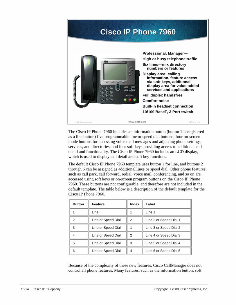
10-14 Cisco IP Telephony Copyright 2000, Cisco Systems, Inc.
© 2000, Cisco Systems, Inc. www.cisco.com CIPT v2.0—10-13
Cisco IP Phone 7960Cisco IP Phone 7960
Professional, Manager—High or busy telephone trafficSix lines—mix directory
numbers or featuresDisplay area: calling
information, feature accessvia soft keys, additionaldisplay area for value-addedservices and applications
Full duplex handsfreeComfort noiseBuilt-in headset connection10/100 BaseT, 3 Port switch
The Cisco IP Phone 7960 includes an information button (button 1 is registered as a line button) five programmable line or speed dial buttons, four on-screen mode buttons for accessing voice mail messages and adjusting phone settings, services, and directories, and four soft keys providing access to additional call detail and functionality. The Cisco IP Phone 7960 includes an LCD display, which is used to display call detail and soft key functions.
The default Cisco IP Phone 7960 template uses button 1 for line, and buttons 2 through 6 can be assigned as additional lines or speed dial. Other phone features, such as call park, call forward, redial, voice mail, conferencing, and so on are accessed using soft keys or on-screen program buttons on the Cisco IP Phone 7960. These buttons are not configurable, and therefore are not included in the default template. The table below is a description of the default template for the Cisco IP Phone 7960.
Button Feature Index Label
1 Line 1 Line 1
2 Line or Speed Dial 2 Line 2 or Speed Dial 1
3 Line or Speed Dial 1 Line 3 or Speed Dial 2
4 Line or Speed Dial 2 Line 4 or Speed Dial 3
5 Line or Speed Dial 3 Line 5 or Speed Dial 4
6 Line or Speed Dial 4 Line 6 or Speed Dial 5
Because of the complexity of these new features, Cisco CallManager does not control all phone features. Many features, such as the information button, soft
Copyright 2000, Cisco Systems, Inc. Cisco IP Phones 10-15
keys, and the on-screen mode buttons cannot be configured, but you can access them locally from the phone.
Use Cisco CallManager to add a Cisco IP Phone 7960 to the database, assign default and custom keypad templates, and configure directory lines.
The asynchronous response mode (ARM) core will implement the following major features:
■ Graphical, soft key centric user interface (UI).
■ Call control using an enhanced version of the skinny station protocol.
■ Connectivity will be through standard TCP/IP for both call control and RTP VoIP streaming over 10/100 Mbps Ethernet.
■ Switch configuration will be through a proprietary IPCP protocol exchange with the up stream switch. The IP address configuration will be through DHCP. CallManager selection will be through a configuration file. The configuration file will contain a prioritized list of CallManagers and will be downloaded through TFTP. The ARM code will be field upgradeable through download of an application image using TFTP. The ARM code will also support a DNS stub resolver to allow the resolution of host names.
The digital signaling processor (DSP) firmware implements the following major audio features:
■ G.711 / G.729 / per-call selectable encode/decode
■ Codec overlays allows per call overlays of larger low-bit-rate code segments from the ARM main memory space via dual port memory.
■ Voice activity detection is an adaptive SNR-based for improved performance under varying noise conditions.
■ Comfort noise generation per-codec selectable comfort noise generation65. Gain/frequency response shaping blocks allows per-call and per-transducer tailoring of gain and frequency response characteristics.
■ Echo control will implement handset, headset and hands free acoustic echo control as required. Characteristics of this control will be per-transducer based.
■ Tone/WAV generation are single/dual sine generation facilities as well as WAV prompt play outs.
■ Selectable audio frame-size is a per-call encode/decode of any speech frames in a 10 ms multiple.

10-16 Cisco IP Telephony Copyright 2000, Cisco Systems, Inc.
© 2000, Cisco Systems, Inc. www.cisco.com CIPT v2.0—10-14
Supported NetworkingProtocols
Supported NetworkingProtocols
• Internet (IP)• Voice over IP (VoIP)• Bootstrap (BootP)• Trivial File Transfer
(TFTP)• Dynamic Host Control
(DHCP)• Cisco Discovery (CDP)• Real-Time (RTP)• User Datagram (UDP)
Cisco IP Phone 7960Cisco IP Phone 7960
The Cisco IP Phone 7960 supports industry standard and Cisco networking protocols required for voice communication. The following are the supported networking protocols on the Cisco IP Phone 7960:
■ Internet Protocol (IP) is a messaging protocol that addresses and sends packets across the network.
■ Voice over IP Protocol (VoIP) enables transfer of voice communications over a data network using the internet protocol.
■ Bootstrap Protocol (BootP) enables a network device, such as the Cisco IP Phone 7960 to discover certain startup information, such as its IP address.
■ Trivial File Transfer Protocol (TFTP) allows transfer of files over the network and enables configuration files specific to the phone type to be obtained.
■ Dynamic Host Control Protocol (DHCP) dynamically allocates and assigns an IP address to network devices. DHCP also enables connection of the IP phone into the network and become operational without manually assigning an IP address and configuring additional required network parameters.
■ Cisco Discovery Protocol (CDP) is a device-discovery protocol that runs on all Cisco-manufactured equipment. Using CDP, a device can advertise its existence to neighboring devices and receive information about neighboring devices in the network. The Cisco IP Phone 7960 uses CDP to communicate information such as auxiliary VLAN ID, per port power management detail, and QoS configuration information with the Cisco Catalyst switch.
■ Real-Time Transport protocol (RTP) enables an audio media stream to be established between two Voice over IP devices.
■ User Datagram Protocol (UDP) is used by the RTP audio media stream and uses UDP ports 16,384 through 32,767.

Copyright 2000, Cisco Systems, Inc. Cisco IP Phones 10-17
Cisco IP Phone Operation
© 2000, Cisco Systems, Inc. www.cisco.com CIPT v2.0—10-15
Cisco IP Phone OperationCisco IP Phone Operation
• Phone and CallManager use a lightweightactive skinny station protocol over TCP/IP
• Skinny station protocol is an open stimulusresponse architecture:–All events at the phone are reported to the
CallManager–All actions at the phone are directed by the
CallManager
The skinny station protocol is an active stimulus/response protocol that has been published. It is lighter than the corresponding H.323 terminal requirements in both function and required message volume. A fully compliant H.323 device would require implementation of H.225 and H.245.
The phone, in conjunction with the proxy services provided by the CallManager service, is H.323 compliant. Voice with G.711 coding and combined with H.225 call setup and H.245 media control are done together.
The ITU-T has created recommendation H.323, which provides mechanisms for establishing, controlling, and clearing information flows, including audio information, between two H.323-compliant terminals. To implement a full H.323-compliant terminal requires a high expenditure for computer power and memory size. An H.323 proxy can be implemented in a relatively high-powered server and can communicate to a simplified, skinny station efficiently using the skinny station messaging system. Within the context of H.323, by implementing the station telephone set as a skinny station over IP and using a proxy for H.225 and H.245 signaling, a relatively inexpensive IP phone (such as an 10Base-T phone) is constructed.
Cisco’s IP phone solution has created a generalized messaging set that uses skinny stations (Cisco IP phones) to coexist in an H.323 environment. Because of the savings in memory size, processor power, and complexity, the IP phone provides a user station that is user friendly and cost effective. When coupled with an H.323 proxy, the skinny station can interoperate with H.323-compliant terminals to establish, control, and clear audio calls.

10-18 Cisco IP Telephony Copyright 2000, Cisco Systems, Inc.
© 2000, Cisco Systems, Inc. www.cisco.com CIPT v2.0—10-16
H.323-Compliant VoiceTerminals
H.323-Compliant VoiceTerminals
• CallManager terminates H.225/H.245 overTCP/IP as an H.323 proxy for the phones,redirecting the media stream to the phone
• Phone terminates the voice media stream overRTP/UDP/IP
H.323 devices are communications devices that comply with the H.323 communications standard. In the CIPT system, NetMeeting and H.323-compliant third-party gateways are considered H.323 devices.
Cisco CallManager differentiates between NetMeeting and third-party gateways by the protocol side assigned (can be configured in devices in Cisco CallManager administration).
You can use the optional media termination point to enable features such as hold and transfer on calls using H.323 gateways or clients and to provide A-law to µ-law conversion.

Copyright 2000, Cisco Systems, Inc. Cisco IP Phones 10-19
© 2000, Cisco Systems, Inc. www.cisco.com CIPT v2.0—10-17
Phone’s Actions on StartupPhone’s Actions on StartupGet IP address, mask, DNS, and so forth
• Static or DHCPGet TFTP server address
• Static address• Option 150 (single IP address)• Option 66 (first IP address or DNS name)• Look up CiscoCM1.your.domain
Get configuration from CallManager TFTP*• List of up to three CallManagers• Region info and keyboard template• Version of code to run
Get new code (one time only)Register with CallManager
1
3
2
4
5
DHCPDNS
CallManagerTFTP
13
245
*Use configuration in Flash after timeout
Useanyone
The Phone’s Actions on Startup 1. When a telephone is plugged into an Ethernet jack, assuming the
prerequisite infrastructure and a CallManager, the first thing that will happen is the telephone will request an IP address from a Dynamic Host Configuration Protocol (DHCP) server. In general, this is the recommended mode of operation. Static addressing can be supplied to the telephone, and you can enter the IP address manually, but this would prevent mobility.
2. As part of that DHCP request, when an IP address is supplied to the telephone, it is also possible to supply the address of the TFTP server, or the CallManager from which the telephone will get its configuration. Once again, the TFTP server address could be specified manually but this would limit adds, moves, and changes and remove some of the benefits. This TFTP server address can be given in several forms: either Option 150 or Option 66 or the Bootstrap Protocol (BOOTP).
3. Once that address has been given, the phone will register itself with the CallManager and download its configuration, which can contain a list of up to five CallManagers that the telephone can use for call control. This creates an extremely resilient system. The phone gets its region information and also the features or functionality that each of the keys will produce.
4. The phone receives any new code it is to run. If, for example, the firmware or the code that each telephone runs is changed, this can be added to the CallManager. Once restarted, each telephone will automatically reload that code. The telephones can be configured to auto register.
5. An administrator rolling out the phones would plug each one in and then assign a number. New phone entries will appear by Media Access Control (MAC) address, which is how the CallManager ties the actual instrument to a telephone number. An alternate, not the normal operation, would occur when you plug in the telephone; CallManager would automatically give that

10-20 Cisco IP Telephony Copyright 2000, Cisco Systems, Inc.
telephone a line number. However, this would make things like directories very difficult to set up.
* Use configuration in Flash after timeout.
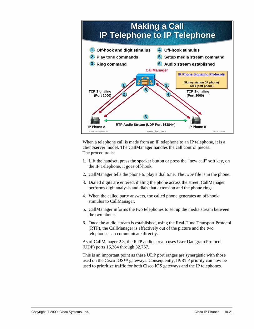
Copyright 2000, Cisco Systems, Inc. Cisco IP Phones 10-21
© 2000, Cisco Systems, Inc. www.cisco.com CIPT v2.0—10-18
CallManager
IP Phone BRTP Audio Stream (UDP Port 16384+) IP Phone A
TCP Signaling(Port 2000)
TCP Signaling(Port 2000)
Off-hook and digit stimulusPlay tone commandsRing command
Off-hook stimulusSetup media stream commandAudio stream established
1
32
4
65
1 3
2 4
6
5
Making a CallIP Telephone to IP Telephone
Making a CallIP Telephone to IP Telephone
IP Phone Signaling Protocols
Skinny station (IP phone)TAPI (soft phone)
IP Phone Signaling Protocols
Skinny station (IP phone)TAPI (soft phone)
When a telephone call is made from an IP telephone to an IP telephone, it is a client/server model. The CallManager handles the call control pieces. The procedure is:
1. Lift the handset, press the speaker button or press the “new call” soft key, on the IP Telephone, it goes off-hook.
2. CallManager tells the phone to play a dial tone. The .wav file is in the phone.
3. Dialed digits are entered, dialing the phone across the street. CallManager performs digit analysis and dials that extension and the phone rings.
4. When the called party answers, the called phone generates an off-hook stimulus to CallManager.
5. CallManager informs the two telephones to set up the media stream between the two phones.
6. Once the audio stream is established, using the Real-Time Transport Protocol (RTP), the CallManager is effectively out of the picture and the two telephones can communicate directly.
As of CallManager 2.3, the RTP audio stream uses User Datagram Protocol (UDP) ports 16,384 through 32,767.
This is an important point as these UDP port ranges are synergistic with those used on the Cisco IOS™ gateways. Consequently, IP/RTP priority can now be used to prioritize traffic for both Cisco IOS gateways and the IP telephones.
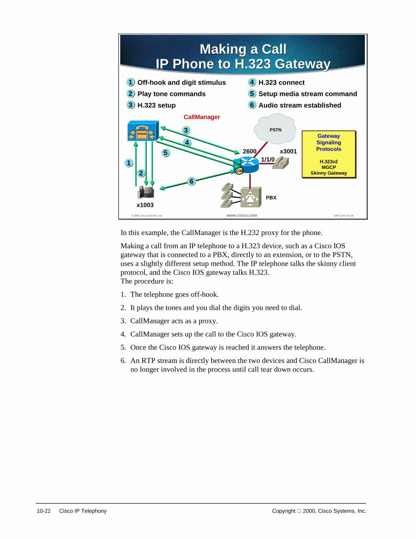
10-22 Cisco IP Telephony Copyright 2000, Cisco Systems, Inc.
© 2000, Cisco Systems, Inc. www.cisco.com CIPT v2.0—10-19
x1003
CallManager
x300126001/1/0
Off-hook and digit stimulusPlay tone commandsH.323 setup
H.323 connectSetup media stream commandAudio stream established
Making a CallIP Phone to H.323 Gateway
Making a CallIP Phone to H.323 Gateway
1
32
4
65
1
3
26
PBX
PSTN
GW
45
GatewaySignalingProtocols
H.323v2MGCP
Skinny Gateway
GatewaySignalingProtocols
H.323v2MGCP
Skinny Gateway
In this example, the CallManager is the H.232 proxy for the phone.
Making a call from an IP telephone to a H.323 device, such as a Cisco IOS gateway that is connected to a PBX, directly to an extension, or to the PSTN, uses a slightly different setup method. The IP telephone talks the skinny client protocol, and the Cisco IOS gateway talks H.323. The procedure is:
1. The telephone goes off-hook.
2. It plays the tones and you dial the digits you need to dial.
3. CallManager acts as a proxy.
4. CallManager sets up the call to the Cisco IOS gateway.
5. Once the Cisco IOS gateway is reached it answers the telephone.
6. An RTP stream is directly between the two devices and Cisco CallManager is no longer involved in the process until call tear down occurs.
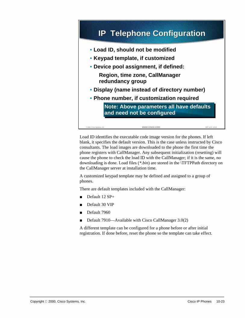
Copyright 2000, Cisco Systems, Inc. Cisco IP Phones 10-23
© 2000, Cisco Systems, Inc. www.cisco.com CIPT v2.0—10-20
IP Telephone ConfigurationIP Telephone Configuration
• Load ID, should not be modified• Keypad template, if customized• Device pool assignment, if defined:
Region, time zone, CallManagerredundancy group
• Display (name instead of directory number)• Phone number, if customization required
Note: Above parameters all have defaultsand need not be configured
Load ID identifies the executable code image version for the phones. If left blank, it specifies the default version. This is the case unless instructed by Cisco consultants. The load images are downloaded to the phone the first time the phone registers with CallManager. Any subsequent initialization (resetting) will cause the phone to check the load ID with the CallManager; if it is the same, no downloading is done. Load files (*.bin) are stored in the \TFTPPath directory on the CallManager server at installation time.
A customized keypad template may be defined and assigned to a group of phones.
There are default templates included with the CallManager:
■ Default 12 SP+
■ Default 30 VIP
■ Default 7960
■ Default 7910—Available with Cisco CallManager 3.0(2)
A different template can be configured for a phone before or after initial registration. If done before, reset the phone so the template can take effect.

10-24 Cisco IP Telephony Copyright 2000, Cisco Systems, Inc.
© 2000, Cisco Systems, Inc. www.cisco.com CIPT v2.0—10-21
Device Parameter MaintenanceDevice Parameter Maintenance
• Use CallManager Administration to configuredefault settings for each type of Cisco IPphone and Cisco access gateway
• Defaults are configured by device type:– Load ID– Keypad template– Device pool
Device types are defined for both current and legacy equipment. Defaults are used at the first registration of the phone with the CallManager to set the device.

Copyright 2000, Cisco Systems, Inc. Cisco IP Phones 10-25
© 2000, Cisco Systems, Inc. www.cisco.com CIPT v2.0—10-22
Load IDLoad ID
• Identifies the executable for the device• Program load is verified during device
registration• Load files (*.bin) are stored in the
\Cisco\TFTPPath directory on the CallManagerserver at CIPT installation
• Updated for the device type when files for thedevice type are updated or patched
There are two types of loads: phone loads and gateway loads. Loads are files that contain updated application software. During installation or upgrade, the latest loads are automatically provided. However, the phone can also receive a load between releases that may contain patches or other information important to the devices that use loads, such as phones or gateways. Users can enter the current phone load ID for the Cisco CallManager version they are running, or leave this field blank to use the system default.
The load ID is verified at every registration (reset) of the phone with the CallManager. Any change will cause the phone to load new code.
There are load IDs for both current and legacy (no longer sold) instruments.
10-26 Cisco IP Telephony Copyright 2000, Cisco Systems, Inc.
© 2000, Cisco Systems, Inc. www.cisco.com CIPT v2.0—10-23
Device PoolDevice Pool
Each device type is assigned a defaultdevice pool:• Region• Date/time group• CallManager group
Device pools reduce administration time by allowing an administrator to specify region, data/time group, and CallManager group criteria that will be common among many devices. When a new device is added, administrators will select the device pool that contains the parameters they want to use for that device. Device pools allow the assignment of the three parameters using a single value.
Device pool assignment causes the phone to obtain the following characteristics defined for the device pool:
■ Region
■ Date/time group
■ Cisco CallManager group
There may be as many device pools as there are unique combinations of these three parameters in a given installation.

Copyright 2000, Cisco Systems, Inc. Cisco IP Phones 10-27
© 2000, Cisco Systems, Inc. www.cisco.com CIPT v2.0—10-24
Auto RegistrationAuto Registration
• Automatically assigns a directory number tothe first line appearance of a Cisco IP Phone
• Done at first registration with CallManager• Off by default• Enabled by configuring a range of directory
numbers using Cisco CallManageradministration
Auto registration allows the system to automatically register IP phones when they are plugged into the system. This feature is turned on and off in CallManager administration.
If auto registration is turned on prior to installing the phones, the phones will automatically register with Cisco CallManager once they are plugged in. If auto registration is not turned on, the phones must be added to the system database manually using Add a New Device in Cisco CallManager administration.

10-28 Cisco IP Telephony Copyright 2000, Cisco Systems, Inc.
© 2000, Cisco Systems, Inc. www.cisco.com CIPT v2.0—10-25
Auto RegistrationDirectory NumbersAuto Registration
Directory Numbers
• New phones are automatically assigned thenext available directory number byCallManager
• A phone moved to a new location keeps thesame directory number
A directory number is the telephone number or internal extension assigned to a Cisco IP phone, for example, 1001. The directory number is assigned to the phone itself, not a location or a user. If the phone is moved, it retains the same directory number. If desired, the directory number can easily be changed using Cisco CallManager administration.
Auto registration is a Cisco CallManager feature that automatically assigns directory numbers to phones as the phones are connected to the network. If administrators want to use auto registration, they must first set a range of directory numbers for auto registration. To save directory numbers, unplug unused IP phones when auto-registration is turned on.

Copyright 2000, Cisco Systems, Inc. Cisco IP Phones 10-29
Power
© 2000, Cisco Systems, Inc. www.cisco.com CIPT v2.0—10-26
Three Ways to Power IP PhonesThree Ways to Power IP Phones
• Inline power– Needs powered linecards for Catalyst
switches– Uses Pins 1, 2, 3, and 6 (same as Ethernet)
for delivering –48V• External power
– Needs external power patch panel– Patch panel delivers –48V over Pins 4, 5, 7,
and 8• Wall power
– Needs DC converter for connecting IP phoneto wall outlet
Combination of ways can be used for redundancyCombination of ways can be used for redundancy
The Cisco IP Phones 7960 and 7910 are capable of using the following three options for power. (Cisco IP Phones 12 SP+ and 30 VIP can only use option 3, wall power):
■ Inline power
— Needs powered linecards for the Catalyst switches.
— The Catalyst will use Pins 1, 2, 3, and 6 (same as Ethernet) for delivering negative 48 volts (-48V)
■ External power
— Needs external power patch panel
— The Patch Panel delivers negative 48 volts (-48 V) over Pins 4, 5, 7, and 8
■ Wall power—needs DC converter for connecting IP phones to a wall outlet.
Note A combination of ways to power the Cisco IP phones can be used for redundancy.

10-30 Cisco IP Telephony Copyright 2000, Cisco Systems, Inc.
© 2000, Cisco Systems, Inc. www.cisco.com CIPT v2.0—10-27
Catalyst Switch and Phone Interaction
Catalyst Switch and Phone Interaction
1. Phone Discovery
2. Provide Power
3. CDP
The following is the process used by the Cisco IP Phones (7960 and 7910) to get inline power from the Catalyst switch.
■ Unpowered phone plugs into powered linecard port, with admin mode on the switch set to auto or on.
■ Port senses the device using phone discovery mechanism and reports it to the supervisor.
■ Supervisor checks power budget, allocates default amount and informs port to apply –48V.
■ Port turns on power to the phone and reports link up to supervisor, once the PHY on the phone is enabled.
■ If phone was powered by external patch panel or wall power, switch port will report link up to supervisor.
■ Phone begins CDP exchange with the switch and gets its VLAN ID (VVID) as well as reports actual power needed for operation.
■ Phone will now send a DHCP request on that VLAN for an IP address.

Copyright 2000, Cisco Systems, Inc. Cisco IP Phones 10-31
10-32 Cisco IP Telephony Copyright 2000, Cisco Systems, Inc.
Configuring Cisco IP Phones and Features
© 2000, Cisco Systems, Inc. www.cisco.com CIPT v2.0—10-28
Configure Cisco IP Phonesand Features
Configure Cisco IP Phonesand Features
The following topics are discussed in thissection:• IP address plan• Adding• Finding• Deleting• Resetting and updating• Assigning a user• Assigning a phone button template• Configure hook flash duration• Display current configuration
Adding and configuring a Cisco IP phone is done using the Cisco CallManager administration. The following concepts are covered in this section:
■ IP address plan
■ Adding
■ Finding
■ Deleting
■ Resetting and updating
■ Assigning a user
■ Assigning a phone button template
■ Configure hook flash duration
■ Display current configuration

Copyright 2000, Cisco Systems, Inc. Cisco IP Phones 10-33
IP Address Plan
© 2000, Cisco Systems, Inc. www.cisco.com CIPT v2.0—10-29
IP Addressing Deployment Options
171.68.249.101 171.68.249.100
IP phone + PC on IP phone + PC on separate switch portsseparate switch ports
Real IP addressesReal IP addresses
171.68.249.100
171.68.249.101
Real IP addressesReal IP addresses
IP phone + PC on IP phone + PC on same switch portssame switch ports
171.68.249.100
IP phone + PC shareIP phone + PC sharethe same devicethe same device
(soft phone)(soft phone)
Real IP addressesReal IP addresses
10.1.1.1
171.68.249.100
IP phone usesIP phone uses“10.0.0.0” Network“10.0.0.0” Network
IP phone + PC onIP phone + PC onsame switch portssame switch ports
171.68.249.10010.1.1.1
IP phone usesIP phone uses“10.0.0.0” network“10.0.0.0” network
IP phone + PC onIP phone + PC onseparate switch portsseparate switch ports
Cisco IP phones need IP addresses and the following recommendations are made for IP addressing deployment. Is there enough address space to support “X” number of phones? If not, use the following recommendations:
■ Continue to use existing addressing for data devices (PCs, workstations, and so forth)
■ Add IP phones with DHCP as the mechanism for getting addressees.
■ If subnets are available in existing address space then use them for IP phones.
■ If not, then use private addressing (network 10 or network 172.16 – 172.20).
■ LAN and private IP WAN will carry these routes and route between both the address space.
■ WAN gateway to Internet should block private addresses, just like today with data devices.
Note Phones don’t work across NAT/PAT/ firewall boundaries today.

10-34 Cisco IP Telephony Copyright 2000, Cisco Systems, Inc.
Adding a New Phone
© 2000, Cisco Systems, Inc. www.cisco.com CIPT v2.0—10-30
Add a New PhoneAdd a New Phone
Select Phone TypeSelect Phone Type
Before a Cisco IP phone can be used, the phone must be added to Cisco CallManager.
Before you begin, the phone must reset after making changes to apply the new settings. These settings are not available for all phone types. Only the settings appropriate to the model selected appear on screen.
Follow these steps to add a Cisco IP phone to Cisco CallManager.
1. Open Cisco CallManager Administration.
2. Select Devices > Add a Device. The Add Device page is displayed.
3. Select Device Type > Phone.
4. Select the appropriate model from the Model drop-down list.
5. Enter the appropriate settings as described in table on the following page.
6. Add a directory number to this phone.
Note These settings are not available for all phone types. Only the settings appropriate to the model selected appear on screen.

Copyright 2000, Cisco Systems, Inc. Cisco IP Phones 10-35
The following table shows IP phone configuration settings.
Field Description Usage Notes
Model Identifies the type of Cisco IP phone. Once you select the model, you cannot modify it.
MAC Address Identifies hardware-based telephones and device name.
Value must be 12 hexadecimal characters.
Device Name Identifies software-based telephones. Value can include 1-128 characters, including alphanumeric, dot, dash, or underscores.
Only available for software-based phones.
Description Clarifies the purpose of the device. Can be user’s name or phones location.
Load Information
Specifies custom software for a Cisco IP phone.
Values entered here override the default values for the current model.
Device Pool The region, date/time groups, and Cisco CallManager group combination.
Location Specifies the remote location accessed using restricted bandwidth connections.
Calling Search Space
Specifies the collection of route partitions searched to determine how a dialed number should be routed.
Button Template Determines the configuration of buttons on a phone and identifies which feature (line, speed dial, and so on) is used for each button.
Not available for software-only phones.
Directory Services URL
Specifies the primary and secondary servers from which the phone obtains directory information.
Used for Cisco IP Phone 7960 only.
Voice Mail URL Specifies the primary and secondary servers from which the phone obtains directory information.
Used for Cisco IP Phone 7960 only.
Outgoing Caller ID Pattern
Specifies the number to send as caller ID for outgoing calls.
Used for H.323 clients only.
Calling Party Selection
Determines what to display if a call to this device is forwarded or transferred.
Used for H.323 clients only.
Caller ID Presentation
Used for H.323 clients only.
Media Termination Point Required
Determines whether or not a media termination point is used to implement features that H.323 does not support (such as hold and transfer).
Used for H.323 clients only.

10-36 Cisco IP Telephony Copyright 2000, Cisco Systems, Inc.
© 2000, Cisco Systems, Inc. www.cisco.com CIPT v2.0—10-31
Adding a Directory NumberAdding a Directory Number
Follow these instructions to add a directory line to a specific phone.
Before you begin, the Cisco IP phone must be added to Cisco CallManager before adding a directory line.
Follow these steps to add a directory number:
1. Open Cisco CallManager Administration.
2. Select Devices > Phone. The Phone Search page displays.
3. Enter search criteria to locate a specific phone. A list of discovered devices appears.
4. Click Device Name. The Phone Configuration page displays, with the lines listed on the left side.
5. Click an unassigned line (Line 1, Line 2, and so on). The Directory Number Configuration page displays.
6. Enter the appropriate settings as described in the table on the following page.
7. Click Insert and Close.

Copyright 2000, Cisco Systems, Inc. Cisco IP Phones 10-37
The following table shows the directory line configuration settings.
Field Description Usage Notes
Directory Number
Directory Number
Indicates a dialable phone number. Values must be 1-32 numeric characters, *, or #.
Unique in combination with partition.
Partition Indicates the route partition to which the directory number belongs.
Can appear in more than one partition.
Unique in combination with the directory number.
Appears only if configured in the system.
Directory Number Settings
Calling Search Space
Collection of partitions that are searched for numbers called from this directory number.
Changes cause update of the numbers listed in the Call Pickup Group field.
Applies to all devices using this directory number.
Call Waiting Specifies whether this directory number uses call waiting when a line is busy (On), responds with a busy signal (Off), or uses the system-wide default setting (default).
Applies to all devices using this directory number.
Call Forward and Pickup Settings
Call Pickup Group
Indicates a number that can be dialed to answer calls to this directory number (in the specified partition).
Forward All Indicates the directory number to which all calls are forwarded.
Any dialable phone number, including an outside destination.
Applies to all devices using this directory number.
Calling Search Space
Indicates the calling search space to use when forwarding to the specified destination.
Applies to all devices using this directory number.
Forward Busy
Indicates the directory number that a call is forwarded to when the line is in use.
Any dialable phone number, including an outside destination.
Applies to all devices using this directory number.
Calling Search Space
Indicates the calling search space to use when forwarding to the specified destination.
Applies to all devices using this directory number.

10-38 Cisco IP Telephony Copyright 2000, Cisco Systems, Inc.
Forward No Answer
Indicates the directory number that a call is forwarded to when no one answers after 4 rings.
Any dialable phone number, including an outside destination.
Applies to all devices using this directory number.
Calling Search Space
Indicates the calling search space to use when forwarding to the specified destination.
Applies to all devices using this directory number.
Appears only if configured in the system.
Line Settings for this Phone
Display Indicates text that appears on the called party's phone when a call is placed from this line.
Maximum of 30 alphanumeric characters.
Typically use the user's name or the directory number.
Applies only to the current device.
Label Indicates the text for the line button on this phone.
Cisco IP Phone 7960—displayed on the LCD.
Other Cisco IP phones—not displayed but could be used when printing button templates.
Applies only to the current device.
Disable ring on this line
Stops the phone from ringing to indicate incoming calls.
Applies only to the current device.
External Phone Number Mask
Indicates phone number (or mask) used to send caller ID information when placing a call from this line.
Maximum of 30 number and "X" characters. The X characters must appear at the end of the pattern.
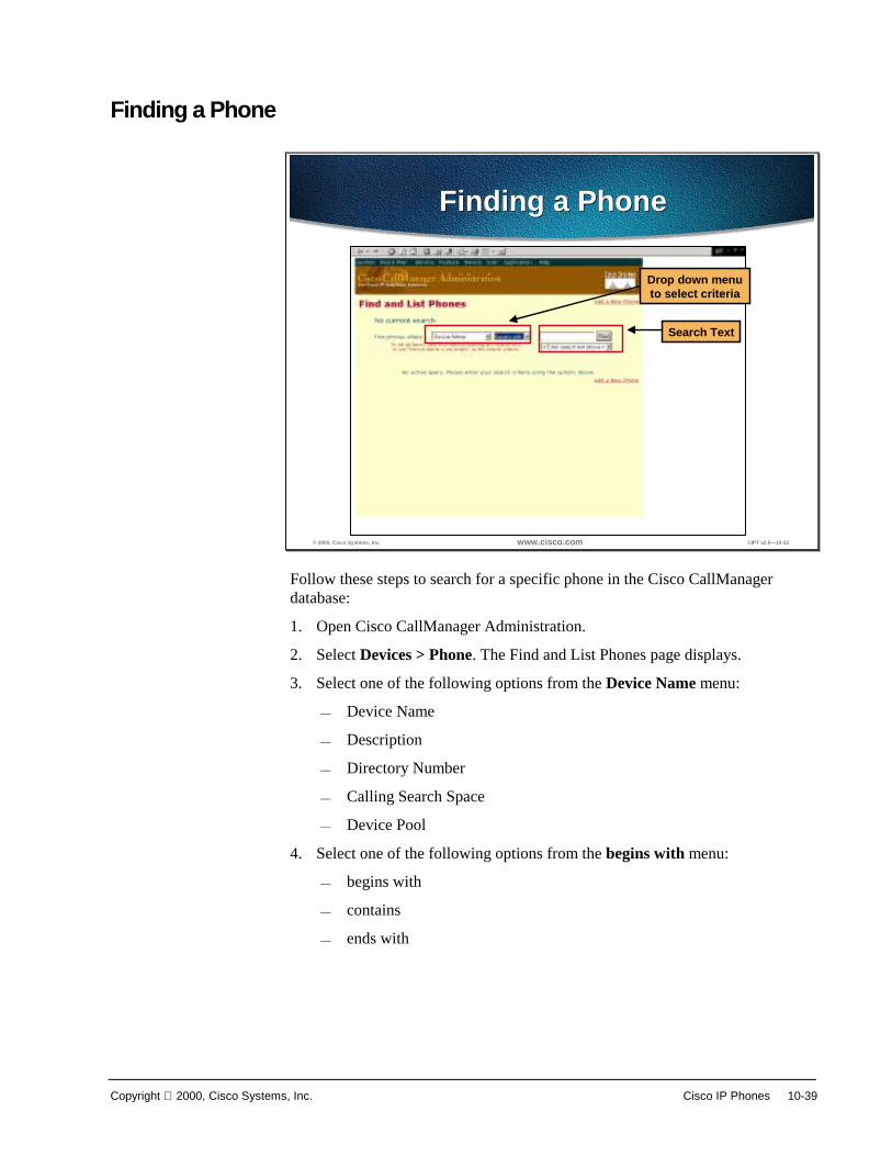
Copyright 2000, Cisco Systems, Inc. Cisco IP Phones 10-39
Finding a Phone
© 2000, Cisco Systems, Inc. www.cisco.com CIPT v2.0—10-32
Finding a PhoneFinding a Phone
Drop down menuto select criteria
Search Text
Follow these steps to search for a specific phone in the Cisco CallManager database:
1. Open Cisco CallManager Administration.
2. Select Devices > Phone. The Find and List Phones page displays.
3. Select one of the following options from the Device Name menu:
— Device Name
— Description
— Directory Number
— Calling Search Space
— Device Pool
4. Select one of the following options from the begins with menu:
— begins with
— contains
— ends with
10-40 Cisco IP Telephony Copyright 2000, Cisco Systems, Inc.
— is exactly
— exists
— is empty
5. Enter the item to search for in the Find field.
6. Click Find. A list of the first 20 discovered devices appears displaying the following:
■ Device icon
■ Device Name
■ Description
■ Device Pool
■ Copy
■ Delete
■ Reset
The total number of devices and pages are also listed on this page.
7. To view the next set of discovered devices, click Next.
Finding a Phone Use searching by Calling Search Space or Device Pool. If calling search space or device pool is selected, the options available in the database display. Select one of these options from the drop-down list box below the Find button:
■ Device Name
■ Description
■ Directory Number
■ Calling Search Space
■ Device Pool
■ Begins with
■ Contains
■ Ends with
■ Is exactly
■ Is not empty
■ Is empty
Finding All Phones in the Database To find all phones registered in the database, select these search criteria:
Device Name is not empty

Copyright 2000, Cisco Systems, Inc. Cisco IP Phones 10-41
Deleting a Phone
© 2000, Cisco Systems, Inc. www.cisco.com CIPT v2.0—10-33
Deleting a PhoneDeleting a Phone
Perform the following procedure to delete a Cisco IP phone from Cisco CallManager:
1. Open Cisco CallManager Administration.
2. Select Devices > Phone. The Phone Search page displays.
3. Enter search criteria to locate a specific phone. A list of discovered devices appears.
4. Click the Delete icon next to the phone you want to delete. A message appears verifying that you want to delete the phone.
5. Click OK.
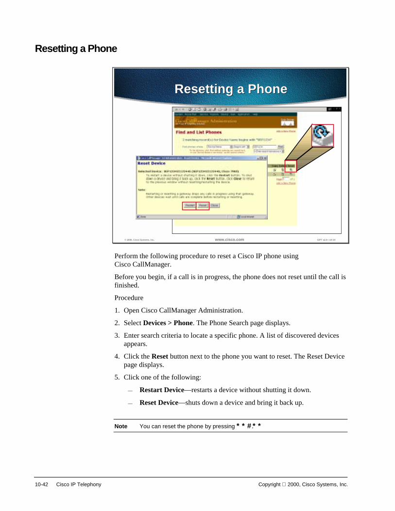
10-42 Cisco IP Telephony Copyright 2000, Cisco Systems, Inc.
Resetting a Phone
© 2000, Cisco Systems, Inc. www.cisco.com CIPT v2.0—10-34
Resetting a PhoneResetting a Phone
Perform the following procedure to reset a Cisco IP phone using Cisco CallManager.
Before you begin, if a call is in progress, the phone does not reset until the call is finished.
Procedure
1. Open Cisco CallManager Administration.
2. Select Devices > Phone. The Phone Search page displays.
3. Enter search criteria to locate a specific phone. A list of discovered devices appears.
4. Click the Reset button next to the phone you want to reset. The Reset Device page displays.
5. Click one of the following:
— Restart Device—restarts a device without shutting it down.
— Reset Device—shuts down a device and bring it back up.
Note You can reset the phone by pressing **#**.

Copyright 2000, Cisco Systems, Inc. Cisco IP Phones 10-43
Updating a Phone
© 2000, Cisco Systems, Inc. www.cisco.com CIPT v2.0—10-35
Updating a PhoneUpdating a Phone
Make changes thenselect “Update”
Perform the following procedure to update a Cisco IP phone from Cisco CallManager:
1. Open Cisco CallManager Administration.
2. Select Devices > Phone. The Phone Search page displays.
3. Enter search criteria to locate a specific phone. A list of discovered devices appears.
4. Click Device Name. The Phone Configuration page displays.
5. Enter desired changes.
6. Click Update.

10-44 Cisco IP Telephony Copyright 2000, Cisco Systems, Inc.
Copying an Existing Phone
© 2000, Cisco Systems, Inc. www.cisco.com CIPT v2.0—10-36
Copying an Existing PhoneCopying an Existing Phone
Make desired changesto selected phone,then select “Copy”
Must change MACaddress beforeselecting insert
When manually adding several similar phones to the Cisco CallManager database, add one and then copy its basic settings to apply to another phone. The MAC address must change before inserting the new phone into the database.
Perform the following procedure to copy a phone's settings:
1. Open Cisco CallManager Administration.
2. Select Devices > Phone. The Phone Search page displays.
3. Enter search criteria to locate a specific phone. A list of discovered devices appears.
4. Click Device Name. The Phone Configuration page displays.
5. Enter desired changes.
6. Click Copy.
7. Enter the MAC address of the new phone.
8. Click Insert.

Copyright 2000, Cisco Systems, Inc. Cisco IP Phones 10-45
Creating Phone Button Templates
© 2000, Cisco Systems, Inc. www.cisco.com CIPT v2.0—10-37
Creating Custom PhoneButton Templates
Creating Custom PhoneButton Templates
• Ensure that features that are described on the quickreference card includes the following:– 12 SP+—Line (one or more), hold, call park, and
forward all– 30 VIP—Line (one or more), call park, and forward all– 7910—Line, hold and transfer– 7960—Line (one or more)
• Consider the nature of each feature in order todetermine how to configure button templates
• Each feature selected must include the number of timesthis feature is to appear on the button template(the feature index)
Use the following guidelines when creating custom button templates:
■ End users receive a quick reference card and/or getting started guide that describes the most basic features. If custom template is created to be used by employees in a company, ensure it includes the following features that are described on the quick reference card:
— 12 SP+—Line (one or more), hold, Call Park, and forward all.
— 30 VIP—Line (one or more), Call Park, and forward all.
— 7960—Line (one or more)
■ Consider the nature of each feature to determine how to configure button template. Multiple buttons can be assigned to speed dial and line. However, usually only one is required of the other features described in the table below.
■ For each feature selected, select the number of times this feature to appears on the button template (the feature index).
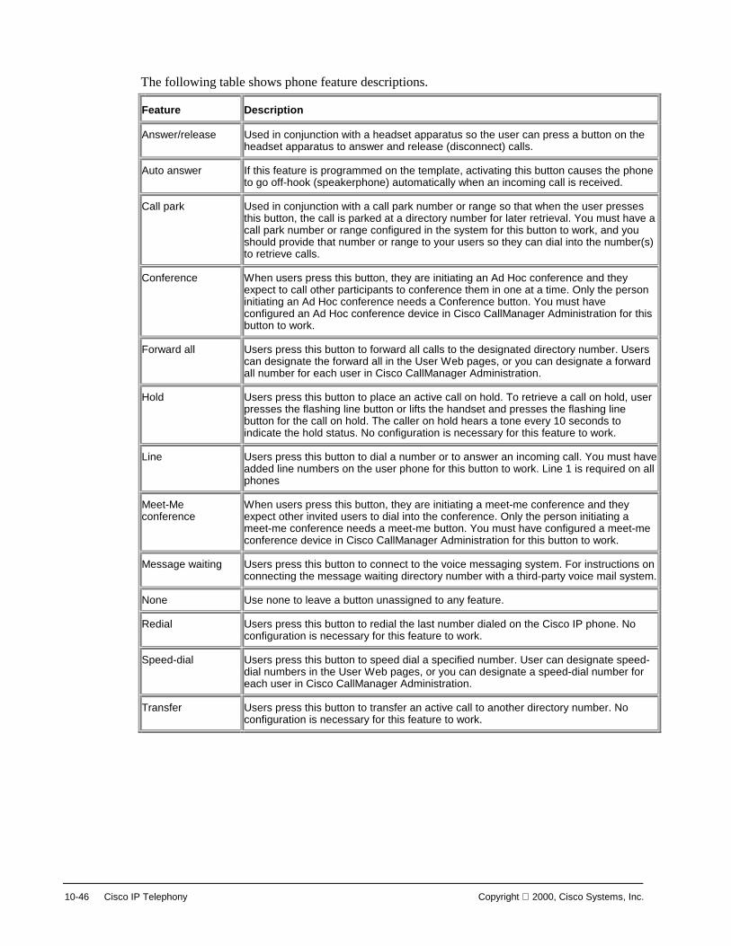
10-46 Cisco IP Telephony Copyright 2000, Cisco Systems, Inc.
The following table shows phone feature descriptions.
Feature Description
Answer/release Used in conjunction with a headset apparatus so the user can press a button on the headset apparatus to answer and release (disconnect) calls.
Auto answer If this feature is programmed on the template, activating this button causes the phone to go off-hook (speakerphone) automatically when an incoming call is received.
Call park Used in conjunction with a call park number or range so that when the user presses this button, the call is parked at a directory number for later retrieval. You must have a call park number or range configured in the system for this button to work, and you should provide that number or range to your users so they can dial into the number(s) to retrieve calls.
Conference When users press this button, they are initiating an Ad Hoc conference and they expect to call other participants to conference them in one at a time. Only the person initiating an Ad Hoc conference needs a Conference button. You must have configured an Ad Hoc conference device in Cisco CallManager Administration for this button to work.
Forward all Users press this button to forward all calls to the designated directory number. Users can designate the forward all in the User Web pages, or you can designate a forward all number for each user in Cisco CallManager Administration.
Hold Users press this button to place an active call on hold. To retrieve a call on hold, user presses the flashing line button or lifts the handset and presses the flashing line button for the call on hold. The caller on hold hears a tone every 10 seconds to indicate the hold status. No configuration is necessary for this feature to work.
Line Users press this button to dial a number or to answer an incoming call. You must have added line numbers on the user phone for this button to work. Line 1 is required on all phones
Meet-Me conference
When users press this button, they are initiating a meet-me conference and they expect other invited users to dial into the conference. Only the person initiating a meet-me conference needs a meet-me button. You must have configured a meet-me conference device in Cisco CallManager Administration for this button to work.
Message waiting Users press this button to connect to the voice messaging system. For instructions on connecting the message waiting directory number with a third-party voice mail system.
None Use none to leave a button unassigned to any feature.
Redial Users press this button to redial the last number dialed on the Cisco IP phone. No configuration is necessary for this feature to work.
Speed-dial Users press this button to speed dial a specified number. User can designate speed-dial numbers in the User Web pages, or you can designate a speed-dial number for each user in Cisco CallManager Administration.
Transfer Users press this button to transfer an active call to another directory number. No configuration is necessary for this feature to work.

Copyright 2000, Cisco Systems, Inc. Cisco IP Phones 10-47
© 2000, Cisco Systems, Inc. www.cisco.com CIPT v2.0—10-38
Adding a Phone ButtonTemplate
Adding a Phone ButtonTemplate
Modify andthen insert
Modify andthen insert
Creating and using templates is a fast way to assign a common button configuration to a large number of phones. For example, if users in a company do not use the conference feature, create a template that reassigns this button to a different feature, such as speed dial. Four default templates are included with the Cisco CallManager: Default 12 SP+ (for all 12-series phones), Default 30 SP+, Default 30 VIP, and Default 7960. When adding phones, assign one of these templates to the phone, or create one.
Before you begin, if you are creating a custom button template, be sure to review the guidelines for creating custom templates.
Follow these steps to create a new button template:
1. Open Cisco CallManager Administration.
2. Select Devices > Phone Button Template.
You must decide which method to use to create this template.
Based on existing template, the new template exactly duplicates the existing template. You must update this new template if you want it to be different than the original.
A new design for a specific phone must have each button set up individually, as follows:
1. Choose the method to create this template.
2. Select a template and click Copy to create a new template based on the selected template. The new template exactly duplicates the existing template and automatically assigns it a new name. Update this new template if you want it to be different than the original.
3. Select a phone and click Continue to create a new template and assign each button individually.

10-48 Cisco IP Telephony Copyright 2000, Cisco Systems, Inc.
4. Make desired changes to the fields described in the phone button configuration settings table below:
Field Description Usage Notes
Template Name Unique name used by CallManager to identify the template.
■ Use any 1-50 characters.
■ Each template must have a unique name.
Feature Specifies the function of the phone button when the template is used.
Index Specifies the instance of a feature so that templates can have multiple instances of the same feature.
For the Cisco IP phone 7960, first button is always Line 1.
Label Text that appears when the template is displayed in the administration interface or printed on some Cisco IP phones.
Name or number for speed dials.
5. Click Insert to add the new template.
6. Click View Button Layout to verify the button layout.

Copyright 2000, Cisco Systems, Inc. Cisco IP Phones 10-49
Modifying a Phone Button Template
© 2000, Cisco Systems, Inc. www.cisco.com CIPT v2.0—10-39
Modifying Phone ButtonTemplates
Modifying Phone ButtonTemplates
Delete PhoneButton TemplateDelete Phone
Button Template
Change NameChange Name
Button FeaturesButton Features
oror
ThenThen
You can make changes to the default template templates included with Cisco CallManager or customer templates you created.
Deleting a Button Template A template that is assigned to one or more devices cannot be deleted. All Cisco IP phones using the template to be deleted must be reassigned to a different button template before you can delete the template.
Follow these steps to delete a button template:
1. Open Cisco CallManager Administration.
2. Select Devices > Phone Button Template. A listing of current button templates appears on the left side of the screen.
3. Click the button template you want to delete. The phone button template configuration page displays.
4. Click Delete. A message displays verifying that you want to delete the template.
5. Click OK to delete the template. A message appears verifying that the template was deleted.
6. Click OK to continue.

10-50 Cisco IP Telephony Copyright 2000, Cisco Systems, Inc.
Renaming a Button Template Renaming a template does not affect the phones that use the template. All Cisco IP phones that use this template continue to use this template once it is renamed.
Follow these steps to rename a button template:
1. Open Cisco CallManager
2. Select Devices > Phone Button Template. A listing of current button templates appears on the left side of the screen.
3. Click the button template you want to rename. The phone button template configuration page displays.
4. Enter the new name in the Template Name field.
5. Click Update. The template re-displays with the new name.
Updating a Button Template Before you begin, remember that when you update a template, the change affects all phones that use the template.
Follow these steps to update an existing button template:
1. Open Cisco CallManager Administration.
2. Select Devices > Phone Button Template. A listing of current button templates appears on the left side of the screen.
3. Click the button template you want to rename. The phone button template configuration page displays.
4. Enter the desired changes.
5. Click Update.
— The template reappears with the changes assigned to it.
— You must restart devices using the template after updating it.
6. Click Restart devices to apply the updated button template.

Copyright 2000, Cisco Systems, Inc. Cisco IP Phones 10-51
Phone Features You can configure Call Park and Call Pickup for phones.
© 2000, Cisco Systems, Inc. www.cisco.com CIPT v2.0—10-40
Phone FeaturesPhone Features
Configuring Call Park Call Park allows you to place a call on hold so that anyone connected to the Cisco CallManager system can retrieve it. One, or a range of Call Park numbers, must be configured in the Cisco CallManager administration for this feature to be used.
For example, if an active call at extension 1000, park the call to a call park extension such as 1234. Anyone connected to the system can then dial 1234 to retrieve the call.
To use Call Park, add the call park extension (in this case, 1234) in Cisco CallManager administration. Add the call park extension when configuring phone features in Cisco CallManager.
Configuring Call Pickup Call pickup allows you to use your phone to answer another ringing phone in your designated call pickup group.
For example, if a user is assigned to a call pickup group, they are able to pick up calls to their group that are sitting in a group queue.
On the Cisco IP Phone 7960 there is a Group Pickup. This feature allows the users to pick up a call in another call pickup group queue when the user has no calls in their own group’s queue.

10-52 Cisco IP Telephony Copyright 2000, Cisco Systems, Inc.
Configure call pickup when configuring phone features in Cisco CallManager administration.

Copyright 2000, Cisco Systems, Inc. Cisco IP Phones 10-53
Error Codes and Status Messages Details of error codes and status messages displayed on the Cisco 12 SP+ and 30 VIP Phones aid in troubleshooting.
© 2000, Cisco Systems, Inc. www.cisco.com CIPT v2.0—10-41
Phone Status CodesPhone Status Codes
• To display a phone’sstatus code, press * *
• Code examples:– 0x00400—Check sum error– 0x00010—TFTP access
error– 0x00001—DHCP disabled
The Cisco IP Phones 12 SP+ and 30 VIP have a digital display and can display status codes. The normal status following a successful registration is 0x04800 boot patch installed, TFTP file received.
The status is a 20-bit code, presented as 5 hex digits in the documentation. Each digit is interpreted independently. These values report status, not just errors.
A detailed list of the status codes can be found in the product documentation.
The following key sequences are examples of keystrokes that can be used to access a range of information on the status of the phone, or to initiate tasks:
■ * Display load
■ ** Display status
■ ** 9 Display call bandwidth used
■ **# Displays DHCP information
■ ** # ** Reset with current saved values

10-54 Cisco IP Telephony Copyright 2000, Cisco Systems, Inc.
© 2000, Cisco Systems, Inc. www.cisco.com CIPT v2.0—10-42
Phone LED Status DisplayPhone LED Status Display
• LEDs on the phonescan be used todetermine networkand software status:
• For example,network connectionstatus
• LED Cause1 DHCP is disabled2 DHCP timeout3 TFTP error4 DNS error
12 SP+ 30 VIP
In addition to the information displayed on the status display, information can also be communicated via the phones LED displays. These are the four line lights on the top left side.
Detailed information on the LED status codes can be found in the user documentation.

Copyright 2000, Cisco Systems, Inc. Cisco IP Phones 10-55
© 2000, Cisco Systems, Inc. www.cisco.com CIPT v2.0—10-43
Phone Reset CausesPhone Reset Causes
• A phone reset can result from:–Power loss–Loss of Gateway–Ethernet connectivity failure–Keypad (local) reset “ * * # * * ”–CallManager Administration directed reset–CallManager restart
• Resetting a phone disconnects any call inprogress
If the phone is reset, a reset cause code will be displayed. The following can result in any of the Cisco IP phones resetting:
■ Power loss
■ Loss of gateway—a gateway is disconnected or powers down.
■ Ethernet connectivity failure—Layer 1 problem
■ Keypad
— Entering ** # ** will cause the phone to reset using the current values for the phone.
— Entering 0.0.0.0 for an IP address will cause the phone to reset.
■ CallManager administration directed reset from the device phone section
■ CallManager restart using control center or server reboot.
During a power outage, if a PC is connected through the hub in the phone, the Ethernet connection to the PC is lost.
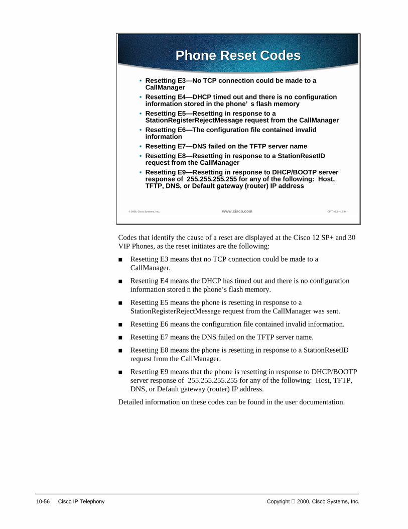
10-56 Cisco IP Telephony Copyright 2000, Cisco Systems, Inc.
© 2000, Cisco Systems, Inc. www.cisco.com CIPT v2.0—10-44
Phone Reset CodesPhone Reset Codes• Resetting E3—No TCP connection could be made to a
CallManager• Resetting E4—DHCP timed out and there is no configuration
information stored in the phone’s flash memory• Resetting E5—Resetting in response to a
StationRegisterRejectMessage request from the CallManager• Resetting E6—The configuration file contained invalid
information• Resetting E7—DNS failed on the TFTP server name• Resetting E8—Resetting in response to a StationResetID
request from the CallManager• Resetting E9—Resetting in response to DHCP/BOOTP server
response of 255.255.255.255 for any of the following: Host, TFTP, DNS, or Default gateway (router) IP address
Codes that identify the cause of a reset are displayed at the Cisco 12 SP+ and 30 VIP Phones, as the reset initiates are the following:
■ Resetting E3 means that no TCP connection could be made to a CallManager.
■ Resetting E4 means the DHCP has timed out and there is no configuration information stored n the phone’s flash memory.
■ Resetting E5 means the phone is resetting in response to a StationRegisterRejectMessage request from the CallManager was sent.
■ Resetting E6 means the configuration file contained invalid information.
■ Resetting E7 means the DNS failed on the TFTP server name.
■ Resetting E8 means the phone is resetting in response to a StationResetID request from the CallManager.
■ Resetting E9 means that the phone is resetting in response to DHCP/BOOTP server response of 255.255.255.255 for any of the following: Host, TFTP, DNS, or Default gateway (router) IP address.
Detailed information on these codes can be found in the user documentation.
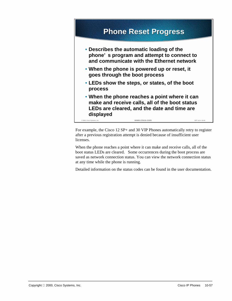
Copyright 2000, Cisco Systems, Inc. Cisco IP Phones 10-57
© 2000, Cisco Systems, Inc. www.cisco.com CIPT v2.0—10-45
Phone Reset ProgressPhone Reset Progress
• Describes the automatic loading of thephone’s program and attempt to connect toand communicate with the Ethernet network
• When the phone is powered up or reset, itgoes through the boot process
• LEDs show the steps, or states, of the bootprocess
• When the phone reaches a point where it canmake and receive calls, all of the boot statusLEDs are cleared, and the date and time aredisplayed
For example, the Cisco 12 SP+ and 30 VIP Phones automatically retry to register after a previous registration attempt is denied because of insufficient user licenses.
When the phone reaches a point where it can make and receive calls, all of the boot status LEDs are cleared. Some occurrences during the boot process are saved as network connection status. You can view the network connection status at any time while the phone is running.
Detailed information on the status codes can be found in the user documentation.

10-58 Cisco IP Telephony Copyright 2000, Cisco Systems, Inc.
Trace Basic Call Processing To accomplish any type of problem determination and resolution, a baseline must be established. The following describes and lists the steps in the call processing from phone to phone.
© 2000, Cisco Systems, Inc. www.cisco.com CIPT v2.0—10-46
Syslog and TraceConfiguration
Syslog and TraceConfiguration
External Syslog Server
Log File, and how oftenthey are created.CM001.log ….
What types of activitiesyou want written to the log(Debug, events, ….)
The syslog and trace configuration allow you to do the following:
■ Determine what types of activities you want written to the log (debug, events)
■ Determine the log file and how often the log files are created.
■ Determine an external syslog server
Note The path to the trace page is in the Cisco CallManager Administration page, services>trace.

Copyright 2000, Cisco Systems, Inc. Cisco IP Phones 10-59
© 2000, Cisco Systems, Inc. www.cisco.com CIPT v2.0—10-47
Sample Trace FileSample Trace File
Cisco CallManager|NodeId: 1, EventId: 1 EventClass: 3 EventInfo: Cisco Call ManagerVersion=<3.0(0.11)> startedCisco CallManager|NodeId: 1, EventId: 1543 EventClass: 2 EventInfo: Database manager startedCisco CallManager|NodeId: 1, EventId: 1542 EventClass: 2 EventInfo: Link manager startedCisco CallManager|NodeId: 1, EventId: 1541 EventClass: 2 EventInfo: Digit analysis startedCisco CallManager|NodeId: 1, EventId: 1540 EventClass: 2 EventInfo: Call control startedCisco CallManager|CallParkManager - ERROR getting_dn_DbNoMoreCallParks - No Call Park numbersRegistered.Cisco CallManager|NodeId: 1, EventId: 1694 EventClass: 2 EventInfo: Supplementary servicesstartedCisco CallManager|NodeId: 1, EventId: 1544 EventClass: 2 EventInfo: Message translationmanager startedCisco CallManager|TitanInit - Waiting on a Connection TCP Port#=2001 IPAddress=172.28.129.22Cisco CallManager|NodeId: 1, EventId: 1539 EventClass: 2 EventInfo: Devices startedCisco CallManager|NodeId: 1, EventId: 103 EventClass: 3 EventInfo: Cisco Call ManagerVersion=<3.0(0.11)> Online
The figure above is an example of a sample trace file. On the far right are descriptions of the events picked up by the trace file.

10-60 Cisco IP Telephony Copyright 2000, Cisco Systems, Inc.
© 2000, Cisco Systems, Inc. www.cisco.com CIPT v2.0—10-48
Normal CDR FieldsNormal CDR Fields
GlobalCallIdentifier This is the global call ID for this call. CI Originator leg call Identifier
CdrDateTime Date/time of call origination
Originators Information
SdlNodeId The node within the CallManager cluster where the call originated
Dsl Originator’s span or port IpAddr IpAddr originators IP address
IpPort Originator’s IP port number Partition Originator’s partition
CdPNumDigits Calling party number CdrCauseElement Cause of termination TransportAddr Media transport address MediaCapabilityStructure Capabilities
The figure above lists the normal call detail record (CDR) fields and a description of the fields.
■ GlobalCalIdentifier is the global call ID for this call.
■ CI is the originator leg call identifier.
■ CdrDateTime is the date/time of call origination.
■ SdlNodeId is the node within the CallManager cluster where the call originated.
■ Dsl indicates the originator’s span or port.
■ IpAddr is the IP address of the originator of the call.
■ IpPort is the originator’s IP port number.
■ Partition is the originator’s partition that they are assigned to.
■ CdPNumDigits is the calling party number.
■ CdrCauseElement is the cause for termination.
■ TransportAddr is the media transport address.
■ MediaCapabilityStructure is the capability for the originating caller.
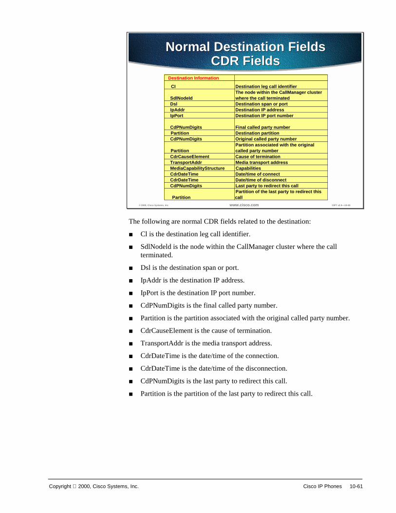
Copyright 2000, Cisco Systems, Inc. Cisco IP Phones 10-61
© 2000, Cisco Systems, Inc. www.cisco.com CIPT v2.0—10-49
Normal Destination FieldsCDR Fields
Normal Destination FieldsCDR Fields
Destination Information
CI Destination leg call identifier
SdlNodeId The node within the CallManager cluster where the call terminated
Dsl Destination span or port IpAddr Destination IP address IpPort Destination IP port number
CdPNumDigits Final called party number Partition Destination partition CdPNumDigits Original called party number
PartitionPartition associated with the original called party number
CdrCauseElement Cause of termination TransportAddr Media transport address MediaCapabilityStructure Capabilities CdrDateTime Date/time of connect CdrDateTime Date/time of disconnect CdPNumDigits Last party to redirect this call
PartitionPartition of the last party to redirect this call
The following are normal CDR fields related to the destination:
■ Cl is the destination leg call identifier.
■ SdlNodeld is the node within the CallManager cluster where the call terminated.
■ Dsl is the destination span or port.
■ IpAddr is the destination IP address.
■ IpPort is the destination IP port number.
■ CdPNumDigits is the final called party number.
■ Partition is the partition associated with the original called party number.
■ CdrCauseElement is the cause of termination.
■ TransportAddr is the media transport address.
■ CdrDateTime is the date/time of the connection.
■ CdrDateTime is the date/time of the disconnection.
■ CdPNumDigits is the last party to redirect this call.
■ Partition is the partition of the last party to redirect this call.

10-62 Cisco IP Telephony Copyright 2000, Cisco Systems, Inc.
© 2000, Cisco Systems, Inc. www.cisco.com CIPT v2.0—10-50
Diagnostic CDR FieldsDiagnostic CDR Fields
GlobalCallIdentifier This is the global call ID for this call, and link to other CDR records
SdlNodeId The node within the CallManager cluster where this record was generated
DirNumThe directory number of the phone that generated this data
PartitionPartition of the directory number (phone) that generated this data
Id CallIdentifierDateTime Daignostics date and timepktssent numberPacketsSentoctetssent numberOctetsSentpktsrecvd numberPacketsReceivedoctetsrecvd numberOctetsReceivedpacketslost numberPacketsLostjitter jitterlatency latency
The following are diagnostic CDR fields:
■ GlobalCallIdentifier is the global caller ID for this call and link to other CDRs.
■ SdlNodeId is the node within the CallManager cluster where this record was generated.
■ DirNum is the directory number of the phone that generated this data.
■ Partition is the partition of the directory number (phone) that generated this data.
■ ID is the call identifier.
■ DateTime is the diagnostics date and time.
■ Pktssent is the number of packets sent.
■ Octetssent is the number of octets sent.
■ Pktsrecvd is the number of packets received.
■ Packetslost is the number of packets lost.
■ Jitter is the jitter.
■ Latency is the latency.

Copyright 2000, Cisco Systems, Inc. Cisco IP Phones 10-63
Summary This section summarizes the concepts you learned in this chapter.
© 2000, Cisco Systems, Inc. www.cisco.com CIPT v2.0—10-52
SummarySummary
• Cisco IP phones use 10BaseT RJ-45 interfacesto connect to the IP network.
• Skinny Station Protocol is used between theCisco CallManager and the Cisco IP phone.
• Auto registration assigns directory numbers tophones connected to the network.
Cisco IP phones are connected to an IP network by a 10BaseT RJ-45 interface. Between Cisco CallManager and the Cisco IP phones the Skinny Station Protocol is used for signaling, call setup, and teardown.
Auto registration is a feature in the Cisco CallManager administration that automatically assigns directory numbers to IP phones connected to the network. Auto registration by default is enabled (on) and can be disabled through Cisco CallManager administration.

10-64 Cisco IP Telephony Copyright 2000, Cisco Systems, Inc.
Review Questions Answer the following questions.
© 2000, Cisco Systems, Inc. www.cisco.com CIPT v2.0—10-53
Review QuestionsReview Questions
1. Is the Cisco CallManager involved with thephone call after an RTP stream is established?
2. What are the networking protocols supportedby the Cisco IP 7960 Phone?
3. What are some events that cause the phone toreset?
Q1) The Cisco CallManager handles the call control when making a call from an IP phone to an IP phone. When an RTP audio stream, using UDP port 16384+, is established between the two IP phones, does the Cisco CallManager stay involved?
Q2) The Cisco IP Phone 7960 supports industry standard and Cisco networking protocols required for voice communication. What are the networking protocols supported by the Cisco IP Phone 7960?
Q3) The Cisco IP phones display a code when a phone resets. What are some of the events that cause a Cisco IP phone to reset?

Copyright 2000, Cisco Systems, Inc. Cisco IP Phones 10-65
11
Cisco CallManager Architecture
Overview Cisco CallManager Version 3.0 architecture significantly enhances the scalability, reliability, and interoperability of the enterprise IP telephony solution. Multiple Cisco CallManager servers are clustered and managed as a single entity. The capability of clustering multiple call-processing servers on an IP network is unique in the industry and highlights the industry-leading architecture of Cisco AVVID. Scalability for up to 10,000 users per cluster is provided. Triple server redundancy improves overall system reliability.
The following topics are discussed in this chapter:
■ Objectives
■ Scalability, Reliability, and Interoperability
■ Cluster Operation and Scalability Guidelines
■ Redundancy
■ Campus Networking Cluster Guidelines
■ Intra and Inter-Cluster Communication
■ SQL Publisher/Subscriber Relationship Within a Cluster
■ Station Registration
■ Written Exercise
■ Summary
■ Review Questions

11-2 Cisco IP Telephony Copyright 2000, Cisco Systems, Inc.
Objectives This section lists the chapter objectives.
© 2000, Cisco Systems, Inc. www.cisco.com CIPT v 2.0—12-3
ObjectivesObjectives
Upon completion of this chapter, you will beable to perform the following tasks:• Define deployment architectures• List the process used by devices to have
redundancy in a cluster• Describe the process that keeps all databases
in a cluster up to date
Upon completion of this chapter, you will be able to perform the following tasks:
■ Given a list of recommendations for building Cisco CallManager clusters, identify the recommendations for a cluster of 5,000 users.
■ Given Cisco IP telephony devices connected to a primary Cisco CallManager and the CallManager fails, list the steps in this process the devices used to ensure reliability through redundancy.
■ Given a cluster of Cisco CallManagers, describe the process used that keeps all the databases in the cluster up to date.
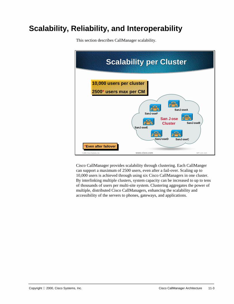
Copyright 2000, Cisco Systems, Inc. Cisco CallManager Architecture 11-3
Scalability, Reliability, and Interoperability This section describes CallManager scalability.
© 2000, Cisco Systems, Inc. www.cisco.com CIPT v 2.0—12-5
Scalability per ClusterScalability per Cluster
San JoseCluster
SanJoseA
SanJoseB
SanJoseCSanJoseD
SanJoseE
10,000 users per cluster
2500* users max per CM
10,000 users per cluster
2500* users max per CM
*Even after failover*Even after failover
SanJoseF
Cisco CallManager provides scalability through clustering. Each CallManger can support a maximum of 2500 users, even after a fail-over. Scaling up to 10,000 users is achieved through using six Cisco CallManagers in one cluster. By interlinking multiple clusters, system capacity can be increased to up to tens of thousands of users per multi-site system. Clustering aggregates the power of multiple, distributed Cisco CallManagers, enhancing the scalability and accessibility of the servers to phones, gateways, and applications.

11-4 Cisco IP Telephony Copyright 2000, Cisco Systems, Inc.
© 2000, Cisco Systems, Inc. www.cisco.com CIPT v 2.0—12-6
CM-A
CM-E
CM-D CM-C
CM-B
Devices homed to CallManager DDevices homed to CallManager D
CM-A
CM-E
CM-D CM-C
CM-B
X
Devices re-home to other CallManagersDevices re-home to other CallManagers
ReliabilityReliability
CallManager D FailsCallManager D Fails
Triple redundancy for devices provides reliability. If a Cisco CallManager fails, the devices that registered to that Cisco CallManager would automatically re-home to other Cisco CallManagers. In a clustered environment devices registered to the one Cisco CallManager could have different secondary Cisco CallManagers to allow distributed re-homing to other Cisco CallManagers within the same cluster.

Copyright 2000, Cisco Systems, Inc. Cisco CallManager Architecture 11-5
© 2000, Cisco Systems, Inc. www.cisco.com CIPT v 2.0—12-7
InteroperabilityInteroperability
Cisco CallManagerCisco CallManager
StationsStations
Skinny
H.323
MGCP
PSTN Apps-(3.0.2)Apps-(3.0.2)
Voice MailVoice Mail
XML AppsXML Apps
GatewaysGateways
Skinny (stimulus)
XML/http
Skinny (stimulus)
SMDI
•TAPI
•JTAPI
The Cisco CallManager architecture provides interoperability with other applications and devices. For example, between the Cisco CallManger and stations (IP phones) the Cisco CallManager uses skinny station (stimulus). The Cisco IP phones use eXtensible Markup Language (XML) to access XML applications.
The Cisco CallManager architecture uses skinny, H.323, and MGCP to communicate with gateways. Skinny (stimulus) is used between the Cisco CallManager and voice mail applications along with Simple Message Desktop Interface (SMDI).
In Cisco CallManager release 3.0(2), the architecture will support Telephony Application Programming Interface (TAPI) or Java TAPI.

11-6 Cisco IP Telephony Copyright 2000, Cisco Systems, Inc.
Cluster Operation and Scalability Guidelines This section describes how to use cluster operation and scalability.
© 2000, Cisco Systems, Inc. www.cisco.com CIPT v 2.0—12-9
What Is a Cisco CallManagerCluster?
What Is a Cisco CallManagerCluster?
(N + 1) Scheme Provides• Enhanced redundancy• Scalability
CM 3.0• Up to 6 CM(s) per cluster• 2500 devices per CM• 16B memory required• 10,000 IP phones per
Cluster
(N + 1) Scheme Provides• Enhanced redundancy• Scalability
CM 3.0• Up to 6 CM(s) per cluster• 2500 devices per CM• 16B memory required• 10,000 IP phones per
Cluster
San JoseCluster
SanJoseA
SanJoseB
SanJoseCSanJoseD
SanJoseE
SanJoseF
Six CallManagers can support as many as ten thousand devices in a Cisco CallManager cluster. The table below provides guidelines for the scaling of devices with CallManager clusters:
Cluster Guidelines Table Number of
Call Managers
Max Devices Per Call Manager
Max Devices Per Call Manager
with N + 1 Redundancy
Max Devices Per
Cluster
Max Devices Per Cluster with N + 1
Redundancy 1 2,500 N/A 2,500 N/A 2 2,500 1,250 5,000 2,500 3 2,500 1,667 7,500 5,000 4 2,500 1,875 10,000 7,500 5 2,500 2,000 10,000 10,000 6 2,500 2,500 10,000 10,000
Registered devices include IP telephones, gateways and Digital Signal Processing (DSP) devices such as transcoding and conferencing resources. The maximum number of registered devices is 2500, hence in the event of the failure of one of the CallManagers within the cluster the maximum number of registered devices under a failure scenario may not exceed 2500.

Copyright 2000, Cisco Systems, Inc. Cisco CallManager Architecture 11-7
Cluster Recommendations
© 2000, Cisco Systems, Inc. www.cisco.com CIPT v 2.0—12-10
Cluster RecommendationsUp to 2,500 Users
Cluster RecommendationsUp to 2,500 Users
Publisher
Primary CallManagerUser’s 1 - 2500
CM-A
CM-B
A cluster of two CallManagers• Single active CallManager• Dedicated Publisher also acts as a standby
A cluster of two CallManagers• Single active CallManager• Dedicated Publisher also acts as a standby
A cluster of two Cisco CallManagers can support up to 2,500 users. Use one of the Cisco CallManagers as the active CallManager and the other as the dedicated backup.
In this example the publisher would be the backup and the subscriber would be the active “primary” CallManager.

11-8 Cisco IP Telephony Copyright 2000, Cisco Systems, Inc.
© 2000, Cisco Systems, Inc. www.cisco.com CIPT v 2.0—12-11
Cluster RecommendationsUp to 5,000 Users
Cluster RecommendationsUp to 5,000 Users
Publisher
Primary CallManagerUser’s 1 - 2500
CM-A
CM-B
CM-CPrimary CallManagerUser’s 2501 - 5000
CM-D Backup for CM_B & CM-C
ClusterCluster
RedundancyGroup
RedundancyGroup
To support up to 5,000 users the recommendation is to use four Cisco CallManagers in one cluster. One Cisco CallManager is the publisher and tertiary Cisco CallManager for redundancy. Two Cisco CallManagers are the primary CallManagers for 2,500 users and both will use the fourth Cisco CallManager as the dedicated backup.
Should Glass House be on a machine by itself? If you have three Cisco CallManagers, the Glass House should be by itself. The name of a machine should not change if SQL Server 7.0 is on it and one database should be in every island of survivability. There is no automated method for moving the Glass House to another machine.

Copyright 2000, Cisco Systems, Inc. Cisco CallManager Architecture 11-9
© 2000, Cisco Systems, Inc. www.cisco.com CIPT v 2.0—12-12
Cluster RecommendationsUp to 10,000 Users
Cluster RecommendationsUp to 10,000 Users
Primary CallManagerUser’s 1 - 2500
Primary CallManagerUser’s 2501 - 5000
Primary CallManagerUser’s 7501 - 10,000
Primary CallManagerUser’s 5001 - 7500
ClusterCluster
RedundancyGroups
RedundancyGroups
Publisher
Backup
Backup
To support up to 10,000 users the recommendation is to use seven Cisco CallManagers in a cluster. One Cisco CallManager would be the publisher for database configurations. Two redundancy groups will be created each supporting up to 5,000 users. The redundancy groups have two active “primary” Cisco CallManagers and one dedicated backup. This model allows to scalability and reliability.
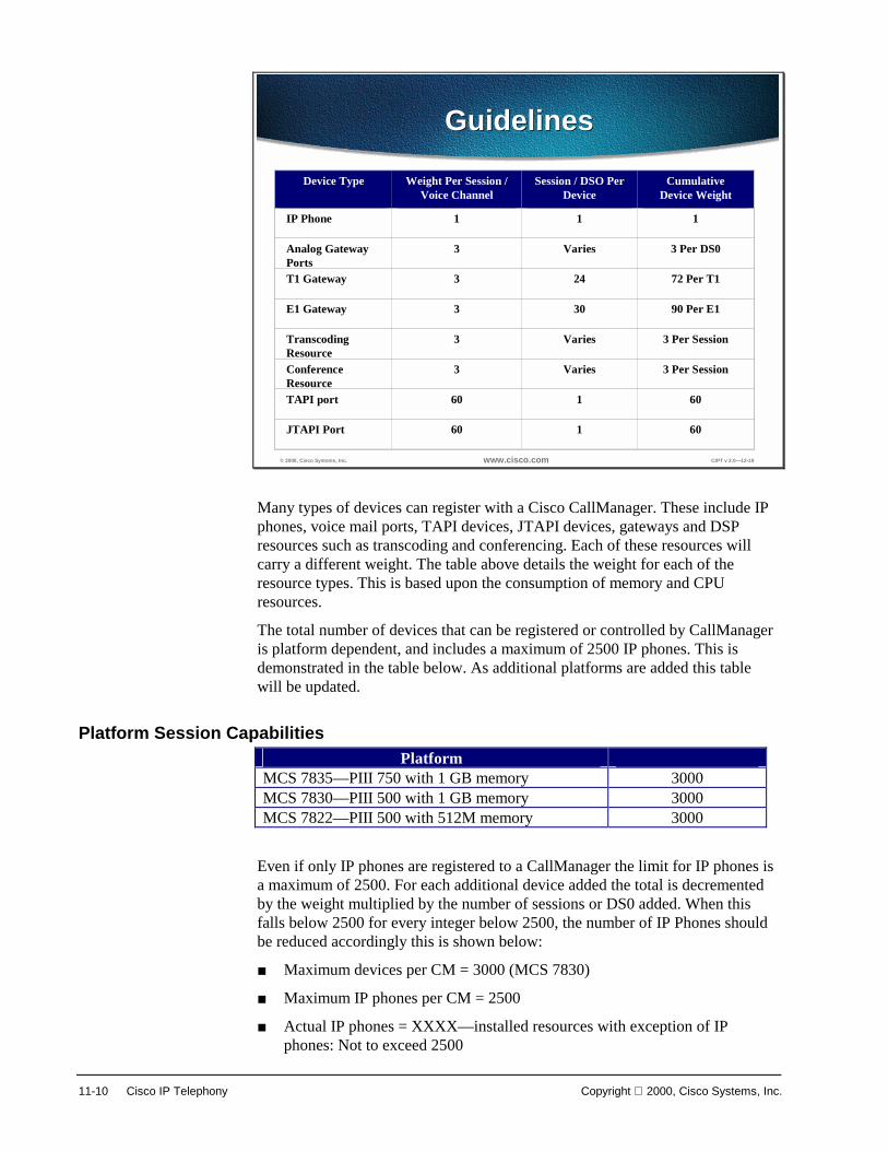
11-10 Cisco IP Telephony Copyright 2000, Cisco Systems, Inc.
© 2000, Cisco Systems, Inc. www.cisco.com CIPT v 2.0—12-19
GuidelinesGuidelines
Device Type Weight Per Session /Voice Channel
Session / DSO PerDevice
CumulativeDevice Weight
IP Phone 1 1 1
Analog GatewayPorts
3 Varies 3 Per DS0
T1 Gateway 3 24 72 Per T1
E1 Gateway 3 30 90 Per E1
TranscodingResource
3 Varies 3 Per Session
ConferenceResource
3 Varies 3 Per Session
TAPI port 60 1 60
JTAPI Port 60 1 60
Many types of devices can register with a Cisco CallManager. These include IP phones, voice mail ports, TAPI devices, JTAPI devices, gateways and DSP resources such as transcoding and conferencing. Each of these resources will carry a different weight. The table above details the weight for each of the resource types. This is based upon the consumption of memory and CPU resources.
The total number of devices that can be registered or controlled by CallManager is platform dependent, and includes a maximum of 2500 IP phones. This is demonstrated in the table below. As additional platforms are added this table will be updated.
Platform Session Capabilities Platform
MCS 7835—PIII 750 with 1 GB memory 3000 MCS 7830—PIII 500 with 1 GB memory 3000 MCS 7822—PIII 500 with 512M memory 3000
Even if only IP phones are registered to a CallManager the limit for IP phones is a maximum of 2500. For each additional device added the total is decremented by the weight multiplied by the number of sessions or DS0 added. When this falls below 2500 for every integer below 2500, the number of IP Phones should be reduced accordingly this is shown below:
■ Maximum devices per CM = 3000 (MCS 7830)
■ Maximum IP phones per CM = 2500
■ Actual IP phones = XXXX—installed resources with exception of IP phones: Not to exceed 2500

Copyright 2000, Cisco Systems, Inc. Cisco CallManager Architecture 11-11
Redundancy This section describes the concept of redundancy.
© 2000, Cisco Systems, Inc. www.cisco.com CIPT v 2.0—12-20
CallManager GroupsCallManager Groups
• Each device– IP phone–Skinny gateway
• Has a prioritized listof up to threeCallManagers, whichit can connect. (maxof 3 recommended)
Primary
Secondary
Last Resort
Peer-to-peer protocols such as H.323 facilitates resiliency by design. The figure above depicts this resiliency scheme for IP Phones.
Within a cluster each registered IP phone can be assigned a list of up to three CallManagers with which it can register for call processing. Shared resources such as gateways using the Skinny Gateway Protocol (SGP) are also capable of using this triple redundancy scheme. The Media Gateway Control Protocol (MGCP) also operates in a similar fashion providing spatial redundancy for call processing.
Each IP telephone maintains active TCP sessions with the primary and secondary configured CallManagers. This facilitates expedited fail-over in the event of failure of the primary CallManager. Upon restoration of the primary, the device reverts to the primary CallManager.
Redundancy is achieved by configuring CallManager groups. A CallManager group is a prioritized list of up to three CallManagers. Individual devices are then assigned to a CallManager group. A CallManager redundancy group is a subset of a cluster; all members of a redundancy group are also members of a cluster.

11-12 Cisco IP Telephony Copyright 2000, Cisco Systems, Inc.
CallManager Redundancy Groups In order to ensure that only a single CallManager is active at a time, all devices should be assigned to a single CallManager redundancy group. This CallManager redundancy group will consist of a prioritized list of up to three CallManagers. On a centralized call-processing cluster only a CallManager redundancy group is recommended this should be the default group. This is shown in the figure below. In this example a CallManager redundancy group of three exists with A as the primary, B the secondary, and C the tertiary CallManager.
© 2000, Cisco Systems, Inc. www.cisco.com CIPT v 2.0—12-21
Redundancy GroupConfiguration
Redundancy GroupConfiguration
Typically, centralized call processing clusters of two CallManagers are deployed. Where an additional level of redundancy is required, a tertiary CallManager can be added. It is recommended that the publisher of the database is the secondary CallManager in the case of a two-CallManager system and the tertiary in the three-CallManager case.

Copyright 2000, Cisco Systems, Inc. Cisco CallManager Architecture 11-13
© 2000, Cisco Systems, Inc. www.cisco.com CIPT v 2.0—12-22
N+1 ExampleN+1 Example
The devices re-home to otherCallManagers, which thenreplicate new route andregistration information toeach other.Since device operation isidentical, users may not noticethat anything happened.
SanJoseA
SanJoseE
SanJoseD SanJoseC
SanJoseB
X
Three devices are homed to SanJoseD. All nodes in the network areconnected and are relaying route and registration information to each other.
SanJoseD powered off. The deviceslose their connection to CM SanJoseD.
The figure above shows how N+1 redundancy works with Cisco CallManagers and attached devices. The following is the process of how N+1 redundancy works:
■ Devices are homed into a Cisco CallManager (San JoseD). All nodes in the network are connected and are relaying route and registration information to each other.
■ San JoseD is powered off. The devices lose their connection to Cisco CallManager San JoseD.
■ The devices re-home to other Cisco CallManagers, which then replicate new route and registration information to each other.
■ Since device operation is identical, users may not notice that anything happened.
11-14 Cisco IP Telephony Copyright 2000, Cisco Systems, Inc.
© 2000, Cisco Systems, Inc. www.cisco.com CIPT v 2.0—12-23
Group IssuesGroup Issues
• CallManager groups are configured manually• Devices are assigned to a CallManager group
manually• No easy way to identify what devices are
members of what CallManager group• No easy way to ensure IP phones are evenly
distributed—No reshuffle command
Some of the issues with Cisco CallManager groups are that all groups are configured manually and the devices are assigned to a group manually. There is no easy way to identify which devices (IP phones, gateways, and so forth) are members of which Cisco CallManager group and ensure the IP phones are evenly distributed.
There is no reshuffle command to have IP phones evenly registered to active Cisco CallManagers and members of Cisco CallManager groups.
The impact of these issues is that there is a limited number of allocated resources to handle these activities and job functions.

Copyright 2000, Cisco Systems, Inc. Cisco CallManager Architecture 11-15
Device Pools
© 2000, Cisco Systems, Inc. www.cisco.com CIPT v 2.0—12-27
Device Pool AttributesDevice Pool Attributes
3 required fields• Region• Time Zone• CallManager redundancy group
Calling search space is optional
Device pools are used to scale and simplify the distribution of CallManager redundancy groups. A device pool allows the following three primary attributes to be assigned globally to a device:
■ Region—Regions are required only if multiple voice codecs are used within an enterprise. Regions define the voice codecs used within and between regions.
■ Date/Time Group—Specifies date and time zone for a device.
■ CallManager redundancy group—Specifies a list of up to three CallManagers, which can be used for call processing in a prioritized list.
In the above example, the same CallManager will be used. However, it is now possible to specify inter region communication codec requirements as follows:
■ Intra-branch communication uses G.711.
■ Inter-branch communication uses G.729 across the wide area network (WAN).
■ All calls to the G.711 region use G.711. This is required when accessing a uOne voice mail system, for example.
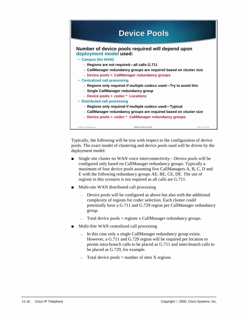
11-16 Cisco IP Telephony Copyright 2000, Cisco Systems, Inc.
© 2000, Cisco Systems, Inc. www.cisco.com CIPT v 2.0—12-28
Device PoolsDevice Pools
Number of device pools required will depend upondeployment model used:• Campus (No WAN)
– Regions are not required—all calls G.711– CallManager redundancy groups are required based on cluster size– Device pools = CallManager redundancy groups
• Centralized call processing– Regions only required if multiple codecs used—Try to avoid this– Single CallManager redundancy group– Device pools = codec * Locations
• Distributed call processing– Regions only required if multiple codecs used—Typical– CallManager redundancy groups are required based on cluster size– Device pools = codec * CallManager redundancy groups
Typically, the following will be true with respect to the configuration of device pools. The exact model of clustering and device pools used will be driven by the deployment model:
■ Single site cluster no WAN voice interconnectivity—Device pools will be configured only based on CallManager redundancy groups. Typically a maximum of four device pools assuming five CallManagers A, B, C, D and E with the following redundancy groups AE, BE, CE, DE. The use of regions in this scenario is not required as all calls are G.711.
■ Multi-site WAN distributed call processing
— Device pools will be configured as above but also with the additional complexity of regions for codec selection. Each cluster could potentially have a G.711 and G.729 region per CallManager redundancy group.
— Total device pools = regions x CallManager redundancy groups.
■ Multi-Site WAN centralized call processing
— In this case only a single CallManager redundancy group exists. However, a G.711 and G.729 region will be required per location to permit intra-branch calls to be placed as G.711 and inter-branch calls to be placed as G.729, for example.
— Total device pools = number of sites X regions.

Copyright 2000, Cisco Systems, Inc. Cisco CallManager Architecture 11-17
© 2000, Cisco Systems, Inc. www.cisco.com CIPT v 2.0—12-29
Device Pool ConfigurationDevice Pool Configuration
In the Cisco CallManager Administration there is the Device Pool Configuration page that is used to configure device pools.
To begin device pool configuration of a device:
1. Select a device from the left column or select New.
2. Select a Region the device is to belong to.
3. Select a Date/Time Group.
4. Select the Cisco CallManager Group for the device
5. Select the Calling Search Space for Auto-Registration.
Select Update or Restart Devices.

11-18 Cisco IP Telephony Copyright 2000, Cisco Systems, Inc.
Campus Networking Cluster Guidelines This section describes campus networking cluster guidelines.
© 2000, Cisco Systems, Inc. www.cisco.com CIPT v 2.0—12-24
IP ConnectivityIP Connectivity
• Clusters are notsupported over theWAN
• Minimum statedbandwidth 10 Mbits
• May need a CM perbuilding in a campusif fiber/copper issingle point of failure
All members of a CallManager cluster are required to be inter-connected via a local area network (LAN). CallManager clusters are not supported over a wide area network (WAN) with CallManager release 3.0. The minimum bandwidth used to interconnect members of a cluster is 10Mbps. The following design constraint considerations should be followed when configuring a campus IP telephony network:
■ There is a maximum of 6 CallManagers per cluster with release 3.0.
■ There is a maximum of 10,000 devices registered.
■ There is a maximum of 2500 devices registered devices per CallManager.
■ This is inclusive of the number of devices registered under failure conditions.
■ Switched infrastructure to the desktop. Shared media is not supported.
Within a switched campus infrastructure adequate bandwidth can generally be assumed. This relies upon appropriate design and capacity planning within the campus in addition to the establishment of a trust boundary and the required queuing. This was covered in the Campus Infrastructure chapter. Consequently there is no requirement for admission control within a campus cluster.

Copyright 2000, Cisco Systems, Inc. Cisco CallManager Architecture 11-19
© 2000, Cisco Systems, Inc. www.cisco.com CIPT v 2.0—12-25
Server PlacementServer Placement
PublisherHighly redundant1 per cluster—data center and UPS
SubscribersOne per building or all ina data center—spatialredundancy
CallManager servers should be distributed within the campus to provide spatial redundancy and resiliency. Many metropolitan sites and campus buildings will potentially have only a single conduit providing IP connectivity to other members of the cluster. In this case it is imperative that should IP connectivity for any reason fail, local call processing is maintained via a local server. In a similar fashion gateway resources for PSTN access should also be strategically placed to provide the highest possible availability.
The publisher is a read-write database and the subscriber is a read-only database.

11-20 Cisco IP Telephony Copyright 2000, Cisco Systems, Inc.
© 2000, Cisco Systems, Inc. www.cisco.com CIPT v 2.0—12-26
Additional TelephonyResources
Additional TelephonyResources
MTP
DSP DSP
DSP DSP
DSPMTPMTPMTP
MTP
Transcodingapplication andconference are notshared resources.
Hence eachCallManager willrequire dedicatedMTP and transcodingresources
GatewaysTranscoding
application andConference
GatewaysTranscoding
application andConference
In the figure above, five buildings/sites exist and at each building/site a Cisco CallManager is placed to provide call processing. This ensures that in the event of a failure, local call processing is possible in each building/site. In cases where diverse routing of fiber facilitates negates the requirement for a local call manager all call processing could be located in a data center or centers.
Resources such as the transcoding application used for transcoding and the conferencing DSP are not shared resources and must be provisioned per Cisco CallManager. Once again, where fault tolerance is required, these resources require duplication and spatial redundancy is recommended. This can be achieved by positioning these resources in strategically placed multi-layer switches.

Copyright 2000, Cisco Systems, Inc. Cisco CallManager Architecture 11-21
Intra and Inter-Cluster Communication This section describes intra-cluster and inter-cluster communication.
© 2000, Cisco Systems, Inc. www.cisco.com CIPT v 2.0—12-30
Feature TransparencyFeature Transparency
Inter and intra-cluster• Basic call setup• G.711 and G.729 calls• Multiparty conference• Call transfer• Hold• Calling line identity
Inter and intra-cluster• Basic call setup• G.711 and G.729 calls• Multiparty conference• Call transfer• Hold• Calling line identity
Intra-cluster only• Calling party name• Call park
Intra-cluster only• Calling party name• Call park
The primary benefit of a Cisco CallManager cluster is the distributed architecture that provides spatial redundancy, resiliency, availability, and survivability for call processing. In addition, within a cluster all features are transparently supported across all devices within that cluster. This enables a distributed PBX to now span an entire campus or high-speed metropolitan area network with full features.
Inter-cluster communication is provided via H.323. This permits a subset of the features to be extended between clusters. Those features currently available for inter-cluster are detailed below:
■ Basic call setup (signaling, digit collection and analysis, media)
■ G.711 and G.729 calls (codec selection and detection)
■ Multiparty conference
■ Call transfer
■ Hold
■ Calling line identity
The features available for intra-cluster, but not inter-cluster, include the following:
■ Calling party name
■ Call park

11-22 Cisco IP Telephony Copyright 2000, Cisco Systems, Inc.
Inter-Cluster Communication
© 2000, Cisco Systems, Inc. www.cisco.com CIPT v 2.0—12-31
Inter-Cluster CommunicationCampus
Inter-Cluster CommunicationCampus
Cluster 2Cluster 1
H.323v2 between clusterMTP not required
In a campus, gatekeeper not required
Where the requirement exists for a campus network that exceeds 10,000 users, additional clusters are required. The required number of CallManagers is greater than five additional CallManagers.
Communication between clusters is achieved using standards based H.323 signaling. With a large campus or metropolitan area network where once again bandwidth is over provisioned and under-subscribed, a method of inter-cluster call admission control is not required. The figure above demonstrates this connectivity between clusters within a local area environment.
In the above diagram the dotted lines represent the configured H.323 inter-cluster links. These are configured in pairs to provide redundancy in the event of loss of IP connectivity to any member of the cluster. The recommendation, however, is to limit inter-cluster configuration to two peers as this in the majority of deployments will provide adequate resiliency.
Unlike CallManager 2.4, the use of a media termination point to allow supplementary services for H.323 devices is not required.
CallManager 3.0 uses the empty capabilities set of H.323v2 that facilitates the opening and closing of logical channels between H.323 devices. CallManager clusters and IOS gateways running version 12.0(7)T or greater use logical channels to provide functionality for supplementary services.

Copyright 2000, Cisco Systems, Inc. Cisco CallManager Architecture 11-23
© 2000, Cisco Systems, Inc. www.cisco.com CIPT v 2.0—12-32
Inter-Cluster CommunicationWAN
Inter-Cluster CommunicationWAN
Cluster 2Cluster 1
H.323 gatekeeper for inter-cluster call admission controlLimit = 100 registered devices
Non redundant = 10 clusters—redundant = 5 clusters
Where clusters are interconnected over a WAN there is a bottleneck for congestion between clusters, and the network should be engineered to accommodate the required volume of voice traffic. In such cases a method of providing call admission control (CAC) is required. Because clusters are interconnected using H.323, an IOS gateway can be added to facilitate this gatekeeper function. Each cluster can be designated as a zone with a maximum configured bandwidth for voice calls.
CallManager requests 128 kbps of bandwidth per inter-cluster call when using a gatekeeper, irrespective of the bandwidth used by the codec. In general, we recommend configuring a single codec for calls that traverse the WAN. In cases where multiple codecs are used, the bandwidth consumed per call should be assumed to be the greater value in all cases. This over-provisioning of bandwidth ensures that all calls are of high quality. Unused bandwidth is available for other traffic classes.
Using gatekeepers provides both inbound and outbound call admission control. A maximum of 10 CallManagers can register with a gatekeeper (five if two CallManagers from each cluster register with the gatekeeper). This method of call admission control is restricted to a single active gatekeeper per network. Redundancy can be achieved using the Hot Standby Routing Protocol (HSRP) between two gatekeepers.
Gatekeeper based call admission control is a policy based scheme; it requires static configuration of available resources and is not network topology aware. It is, therefore, necessary to restrict gatekeeper based call admission control schemes to hub and spoke topologies with the redundant gatekeeper or gatekeepers (using HSRP) located at the hub. The WAN must be provisioned accordingly, and the voice priority queue must be dimensioned to support all admitted calls.

11-24 Cisco IP Telephony Copyright 2000, Cisco Systems, Inc.
© 2000, Cisco Systems, Inc. www.cisco.com CIPT v 2.0—12-33
Recommended BandwidthConfiguration
Recommended BandwidthConfiguration
Number ofInter-ClusterCalls
BandwidthRequired per Call
Bandwidth Requiredon WAN Links(LLQ/CBWFQ1)
BandwidthConfigured onGatekeeper
WithoutcRTP2
WithoutcRTP
WithoutcRTP
WithcRTP
WithcRTP
WithcRTP
25
10
24 Kbps24 Kbps
24 Kbps12 Kbps12 Kbps
12 Kbps 240 Kbps120 Kbps48 Kbps
120 Kbps60 Kbps24 Kbps
1.280 Mbps640 Kbps256 Kbps
1.280 Mbps640 Kbps256 Kbps
Inter-Cluster CallsUsing G.729
Inter-Cluster CallsUsing G.729
1. Low latency queuing/class based weighted fair queuing2. Compressed Real-time Transport Protocol
1. Low latency queuing/class based weighted fair queuing2. Compressed Real-time Transport Protocol
© 2000, Cisco Systems, Inc. www.cisco.com CIPT v 2.0—12-34
Recommended BandwidthConfiguration
Recommended BandwidthConfiguration
Number ofInter-ClusterCalls
BandwidthRequired per Call
Bandwidth Requiredon WAN Links(LLQ/CBWFQ)
BandwidthConfigured onGatekeeper
2510
80 Kbps80 Kbps80 Kbps 800 Kbps
400 Kbps160 Kbps
1.280 Mbps640 Kbps256 Kbps
Inter-Cluster CallsUsing G.711
Inter-Cluster CallsUsing G.711
The tables above provide recommendations for bandwidth configuration for inter-cluster calls.
Use these tables to ensure enough bandwidth between clusters to ensure quality voice.
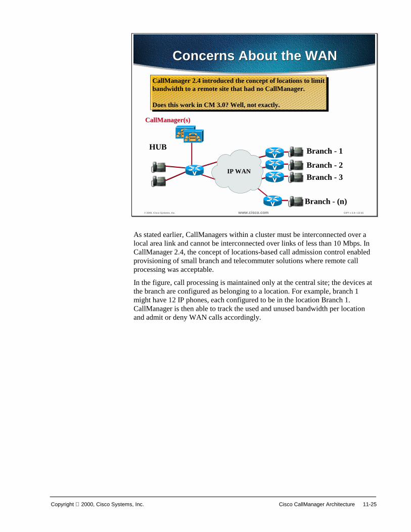
Copyright 2000, Cisco Systems, Inc. Cisco CallManager Architecture 11-25
© 2000, Cisco Systems, Inc. www.cisco.com CIPT v 2.0—12-35
Concerns About the WANConcerns About the WAN
CallManager 2.4 introduced the concept of locations to limitbandwidth to a remote site that had no CallManager.
Does this work in CM 3.0? Well, not exactly.
CallManager 2.4 introduced the concept of locations to limitbandwidth to a remote site that had no CallManager.
Does this work in CM 3.0? Well, not exactly.
CallManager(s)CallManager(s)
IP WAN
HUB Branch - 1
Branch - (n)
Branch - 2Branch - 3
As stated earlier, CallManagers within a cluster must be interconnected over a local area link and cannot be interconnected over links of less than 10 Mbps. In CallManager 2.4, the concept of locations-based call admission control enabled provisioning of small branch and telecommuter solutions where remote call processing was acceptable.
In the figure, call processing is maintained only at the central site; the devices at the branch are configured as belonging to a location. For example, branch 1 might have 12 IP phones, each configured to be in the location Branch 1. CallManager is then able to track the used and unused bandwidth per location and admit or deny WAN calls accordingly.

11-26 Cisco IP Telephony Copyright 2000, Cisco Systems, Inc.
© 2000, Cisco Systems, Inc. www.cisco.com CIPT v 2.0—12-36
Locations and ClusteringLocations and Clustering
For locations to work, all devices must register to a single CM.Locations only works with a cluster of two (primary and backup).
For locations to work, all devices must register to a single CM.Locations only works with a cluster of two (primary and backup).
CampusCluster
Branch - 1
Branch - (n)
Branch - 2
Branch - 3WAN
Cluster
H.323
With CallManager 3.0, a dedicated CallManager cluster is required with a single active CallManager to maintain call state and call admission control.
The maximum number of users per CallManager is 2500.
To ensure that all only a single CallManager is active at a time, all devices should be assigned to a single CallManager redundancy group. This CallManager redundancy group consists of a prioritized list of up to three CallManagers. On a centralized call processing cluster, only a single CallManager redundancy group is recommended; this should be the default group.
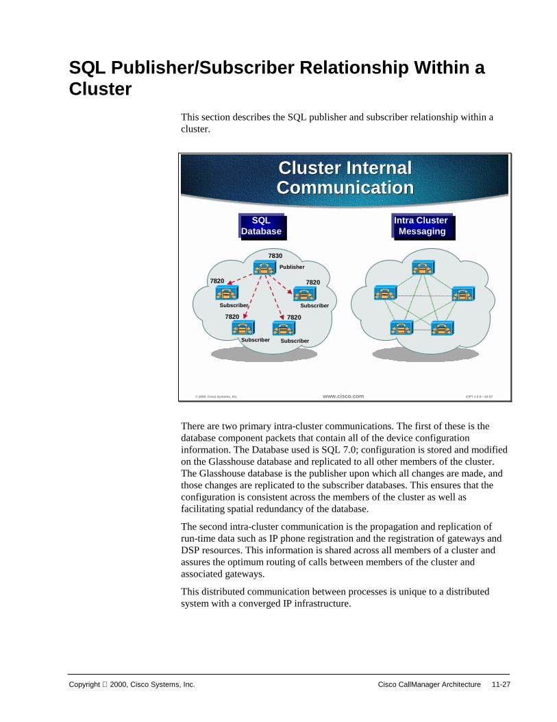
Copyright 2000, Cisco Systems, Inc. Cisco CallManager Architecture 11-27
SQL Publisher/Subscriber Relationship Within a Cluster
This section describes the SQL publisher and subscriber relationship within a cluster.
© 2000, Cisco Systems, Inc. www.cisco.com CIPT v 2.0—12-37
Cluster InternalCommunicationCluster InternalCommunication
Intra Cluster Messaging
Intra Cluster Messaging
SQLDatabase
SQLDatabase
Publisher
Subscriber
Subscriber Subscriber
Subscriber
7830
7820
78207820
7820
There are two primary intra-cluster communications. The first of these is the database component packets that contain all of the device configuration information. The Database used is SQL 7.0; configuration is stored and modified on the Glasshouse database and replicated to all other members of the cluster. The Glasshouse database is the publisher upon which all changes are made, and those changes are replicated to the subscriber databases. This ensures that the configuration is consistent across the members of the cluster as well as facilitating spatial redundancy of the database.
The second intra-cluster communication is the propagation and replication of run-time data such as IP phone registration and the registration of gateways and DSP resources. This information is shared across all members of a cluster and assures the optimum routing of calls between members of the cluster and associated gateways.
This distributed communication between processes is unique to a distributed system with a converged IP infrastructure.

11-28 Cisco IP Telephony Copyright 2000, Cisco Systems, Inc.
© 2000, Cisco Systems, Inc. www.cisco.com CIPT v 2.0—12-38
Internal CommunicationInternal Communication
• Database used is SQL 7.0 Standard Edition + SP 2– 1 publisher per cluster– Remaining CMs are subscribers– (N -1) TCP connections– All configuration changes made on publisher
• CallManager (real time data)– Fully meshed.– (N * (N - 1)) TCP connections
• 6 CM’s = (6 x 5) = 30 connections• 25 CM’s = (25 x 24) = 600 connections
– Real time data—phone and gateway registrations, and so forth
The Structured Query Language (SQL) 7.0 Standard Edition plus Service Pack 2 is used to communicate internally in the Cisco CallManager cluster. There can only be one publisher per cluster, which makes the remaining Cisco CallManagers subscribers. All the configuration changes are made on the publisher. The following is a formula to calculate the amount of TCP connections within a cluster: (N -1) TCP connections (25CMs = 24 connections).
The Cisco CallManager cluster is fully meshed and communicates using real time data. In a fully meshed environment the real time data is used to communicate during phone/gateway registrations. The following is a formula to calculate the amount of TCP connections within a fully meshed cluster: (N * (N - 1)) TCP connections (6 CMs = (6 x 5) = 30 connections; 25 CMs = (25 x 24) = 600 connections).

Copyright 2000, Cisco Systems, Inc. Cisco CallManager Architecture 11-29
© 2000, Cisco Systems, Inc. www.cisco.com CIPT v 2.0—12-39
Replication of DatabaseReplication of Database
• Transactionalprocess
• Immediately unlessthe link is down
• Transaction logreplicates whenpossible
Publisher
Subscriber Subscriber
local database
local database local database
1Transaction
log
2
The replication of the database within a Cisco CallManager cluster happens in the following way:
■ Changes made to the publisher’s database are replicated out via transactional process.
■ Changes happen immediately unless the link is down .
■ If the link is down, SQL keeps a transaction log and replicates the data when possible.
■ The subscriber database is “read-only.”

11-30 Cisco IP Telephony Copyright 2000, Cisco Systems, Inc.
© 2000, Cisco Systems, Inc. www.cisco.com CIPT v 2.0—12-40
The RelationshipThe Relationship
• The publishing(primary) reads its owndatabase
• The subscribing serverslook to the primary’sdatabase for theirinformation
• In the event of a failure,the subscribing serversread local copy ofdatabase
Publisher
Subscriber Subscriber
local database
local database local database
1
2
The relationship between Cisco CallManager publisher and subscriber databases within a cluster happens in the following way:
■ The publishing (primary) database reads its own local database for information.
■ The subscribing (or attached CMs in the same cluster) servers look to the primary database for their information
In the event of a failure, they will read their local copy of the database.

Copyright 2000, Cisco Systems, Inc. Cisco CallManager Architecture 11-31
Station Registration This section describes station registration.
© 2000, Cisco Systems, Inc. www.cisco.com CIPT v 2.0—12-42
Station RegistrationStation Registration
CC DA
LC1000
1. Line register request2. Pattern lookup request3. Pattern lookup response4. Create5. Line register confirm6. Station registers DN7. DA register DN
1. Line register request2. Pattern lookup request3. Pattern lookup response4. Create5. Line register confirm6. Station registers DN7. DA register DN
LineManager
1
4
5
1
23
6
To other CMsTo other CMs
Station
7
LC = Line control .. CC = Call control .. DA = Digit analysisLC = Line control .. CC = Call control .. DA = Digit analysis
Process uses “skinny”Process uses “skinny”
The figure above illustrates the internal process used by a Cisco CallManager when a station (IP phone or gateway) registers. The station is plugged into the network and a line register request is sent to the line manager:
■ The line manager does a pattern lookup request in digit analysis (DA) to see which directory numbers are available and then receives a pattern lookup response from the digit analysis.
■ The line manager then creates a directory number (DN) in the line control (LC) and then sends a line register confirmation to the station.
■ The station then registers the directory number with line control and then line control registers the directory number with digit analysis.

11-32 Cisco IP Telephony Copyright 2000, Cisco Systems, Inc.
© 2000, Cisco Systems, Inc. www.cisco.com CIPT v 2.0—12-43
Station RegistrationMultiline OperationStation RegistrationMultiline Operation
• Shared line appearances operate throughforwarded registrations
• When a station registers with theCallManager, the CallManager determines ifany other CallManagers are managing one ofits lines (DNs)
• If so, the CallManager maintains the stationregistration but forwards call processingmessages to the other node
If stations share line appearances, those shared line appearances will operate through forwarded registration.
If a station registers with the a Cisco CallManager (A) and the Cisco CallManager (A) determines that other Cisco CallManagers (X) are managing one of its directory numbers, the Cisco CallManager (A) will maintain the station registration and forward call processing messages to the other Cisco CallManager (X) managing the directory number.
The next figure illustrates how the above description of multi-line operation occurs internally on the Cisco CallManagers.
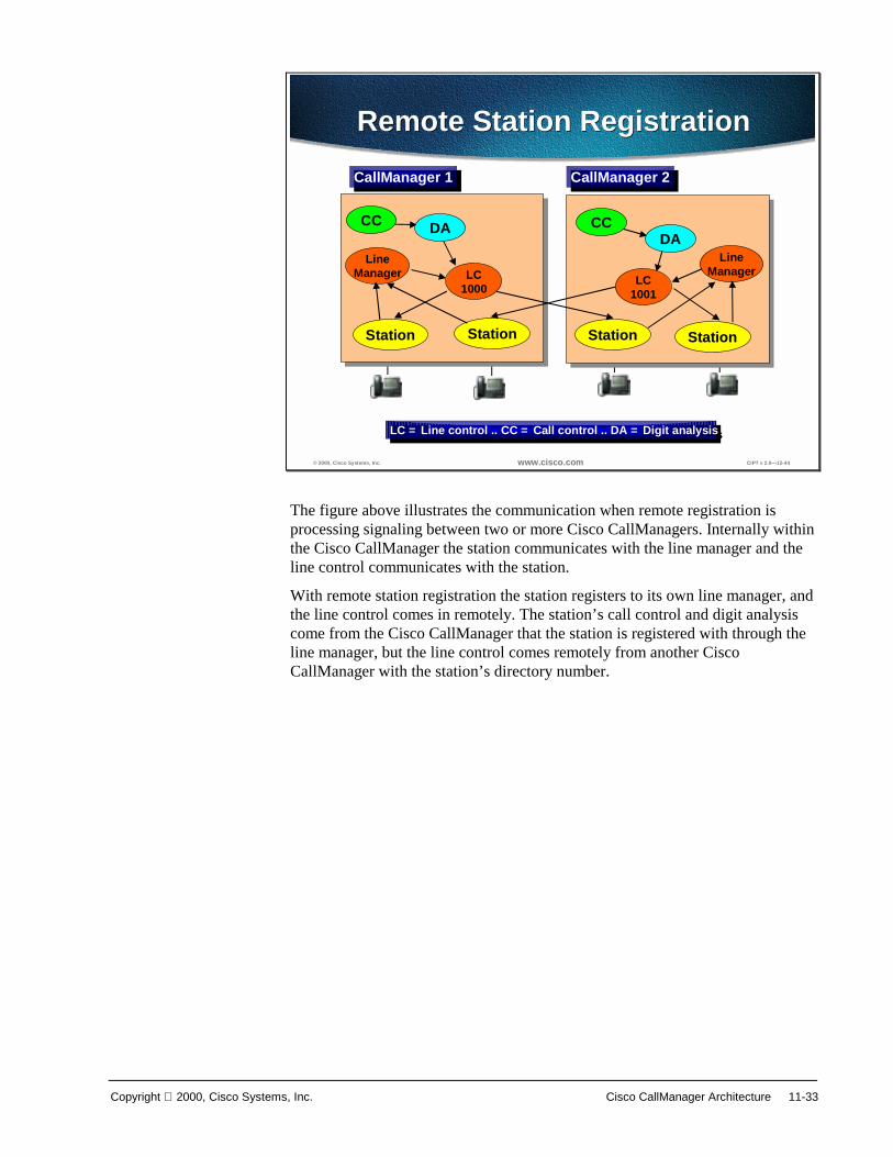
Copyright 2000, Cisco Systems, Inc. Cisco CallManager Architecture 11-33
© 2000, Cisco Systems, Inc. www.cisco.com CIPT v 2.0—12-44
Remote Station RegistrationRemote Station Registration
CallManager 1CallManager 1 CallManager 2CallManager 2
StationStation Station Station
LC = Line control .. CC = Call control .. DA = Digit analysisLC = Line control .. CC = Call control .. DA = Digit analysis
CC CCDADA
LC1000
LC1001
LineManager
LineManager
The figure above illustrates the communication when remote registration is processing signaling between two or more Cisco CallManagers. Internally within the Cisco CallManager the station communicates with the line manager and the line control communicates with the station.
With remote station registration the station registers to its own line manager, and the line control comes in remotely. The station’s call control and digit analysis come from the Cisco CallManager that the station is registered with through the line manager, but the line control comes remotely from another Cisco CallManager with the station’s directory number.

11-34 Cisco IP Telephony Copyright 2000, Cisco Systems, Inc.
© 2000, Cisco Systems, Inc. www.cisco.com CIPT v 2.0—12-45
Station Registration SequenceStation Registration Sequence
LC1000
LineManager
LineManager
DA DA
StationStation
1
2
4
3
5
6
8
9
12
1. Line register request2. Pattern lookup request3. Pattern lookup response4. Create5. Line register confirm6. DA register DN7. DA register DN8. Line register request9. Pattern lookup request10.Pattern lookup response11.Line register confirm12.DA register DN
1. Line register request2. Pattern lookup request3. Pattern lookup response4. Create5. Line register confirm6. DA register DN7. DA register DN8. Line register request9. Pattern lookup request10.Pattern lookup response11.Line register confirm12.DA register DN
Signaling SequenceSignaling Sequence7
710
11
When a station registers within a clustered environment the signaling sequence is expanded to check with the other Cisco CallManagers in the cluster for duplication of directory numbers.
The figure represents all of the components of a Cisco CallManager and has a local station and remote station registering with the same directory number provided by line control. The remote station will go to the local Cisco CallManager for call control and will go to the remote Cisco CallManager for directory number and line control.

Copyright 2000, Cisco Systems, Inc. Cisco CallManager Architecture 11-35
© 2000, Cisco Systems, Inc. www.cisco.com CIPT v 2.0—12-46
Gateway RegistrationGateway Registration
CC DM
Route List
1
To other CMsTo other CMs
Station Gateway
CC DM
Route List
1
To other CMsTo other CMs
Station Gateway
2nd gateway (same route list)2nd gateway (same route list)
GWGW GWGW
Gateway devices register with the CallManager internally. The Cisco CallManager goes through the following process:
■ The gateway device registers with the device manager (DM).
■ The route list information is propagated to all Cisco CallManagers in the Cluster.
■ The gateway devices are high traffic devices hence each Cisco CallManager maintains control of calls that are originated locally.
There can be a second gateway that registers with a different Cisco CallManager with the same route list.
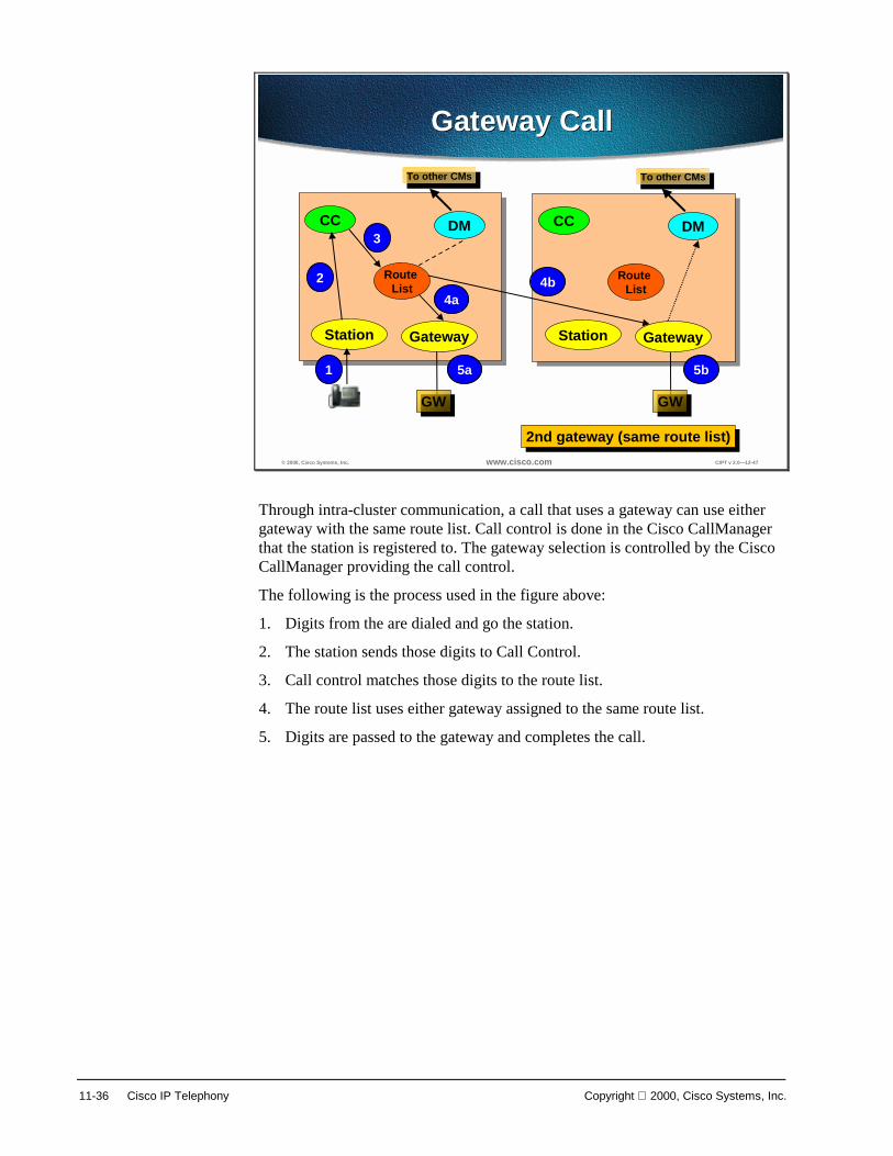
11-36 Cisco IP Telephony Copyright 2000, Cisco Systems, Inc.
© 2000, Cisco Systems, Inc. www.cisco.com CIPT v 2.0—12-47
Gateway CallGateway Call
CC DM
Route List
1
To other CMsTo other CMs
Station Gateway
CC DM
Route List
1
To other CMsTo other CMs
Station Gateway
2nd gateway (same route list)2nd gateway (same route list)
GWGW GWGW
1
2
3
4b4a
5a 5b
Through intra-cluster communication, a call that uses a gateway can use either gateway with the same route list. Call control is done in the Cisco CallManager that the station is registered to. The gateway selection is controlled by the Cisco CallManager providing the call control.
The following is the process used in the figure above:
1. Digits from the are dialed and go the station.
2. The station sends those digits to Call Control.
3. Call control matches those digits to the route list.
4. The route list uses either gateway assigned to the same route list.
5. Digits are passed to the gateway and completes the call.
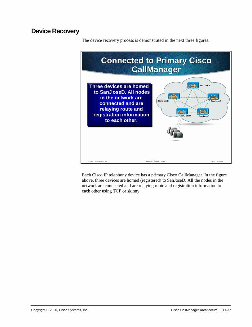
Copyright 2000, Cisco Systems, Inc. Cisco CallManager Architecture 11-37
Device Recovery The device recovery process is demonstrated in the next three figures.
© 2000, Cisco Systems, Inc. www.cisco.com CIPT v 2.0—12-49
Connected to Primary CiscoCallManager
Connected to Primary CiscoCallManager
Three devices are homedto SanJoseD. All nodes
in the network areconnected and arerelaying route and
registration informationto each other.
Three devices are homedto SanJoseD. All nodes
in the network areconnected and arerelaying route and
registration informationto each other.
SanJoseA
SanJoseE
SanJoseD SanJoseC
SanJoseB
Each Cisco IP telephony device has a primary Cisco CallManager. In the figure above, three devices are homed (registered) to SanJoseD. All the nodes in the network are connected and are relaying route and registration information to each other using TCP or skinny.
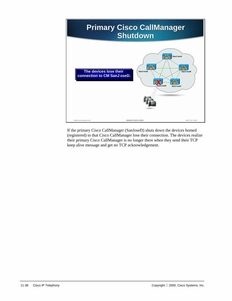
11-38 Cisco IP Telephony Copyright 2000, Cisco Systems, Inc.
© 2000, Cisco Systems, Inc. www.cisco.com CIPT v 2.0—12-50
Primary Cisco CallManagerShutdown
Primary Cisco CallManagerShutdown
The devices lose theirconnection to CM SanJoseD.
The devices lose theirconnection to CM SanJoseD.
SanJoseA
SanJoseE
SanJoseD SanJoseC
SanJoseB
X
If the primary Cisco CallManager (SanJoseD) shuts down the devices homed (registered) to that Cisco CallManager lose their connection. The devices realize their primary Cisco CallManager is no longer there when they send their TCP keep alive message and get no TCP acknowledgement.

Copyright 2000, Cisco Systems, Inc. Cisco CallManager Architecture 11-39
© 2000, Cisco Systems, Inc. www.cisco.com CIPT v 2.0—12-51
Re-home to Secondary CiscoCallManagers
Re-home to Secondary CiscoCallManagers
Then replicate new route andregistration information to eachother.The devices experience only abrief outage during rehoming• Calls in progress are
maintained if betweentwo phones on failedCM.
• Gateway calls aredropped (currently)
Since device operation isidentical, users may not noticethat anything happened.
SanJoseA
SanJoseE
SanJoseD SanJoseC
SanJoseB
X
While the devices were still registered to the primary Cisco CallManager, TCP messages were still being sent to the secondary. The devices now home to the secondary Cisco CallManagers. Each device can have separate secondary Cisco CallManagers.
The devices experience a brief outage during re-homing. If a call between two phones on the same Cisco CallManager is in progress when this happens, the call will be maintained. When the calls are terminated and the phones are on-hook, the phones will then TCP to the primary, get no acknowledgement, and then re-home to the secondary Cisco CallManager.
However, if the call is across multiple Cisco CallManagers or gateways, the calls will be dropped.
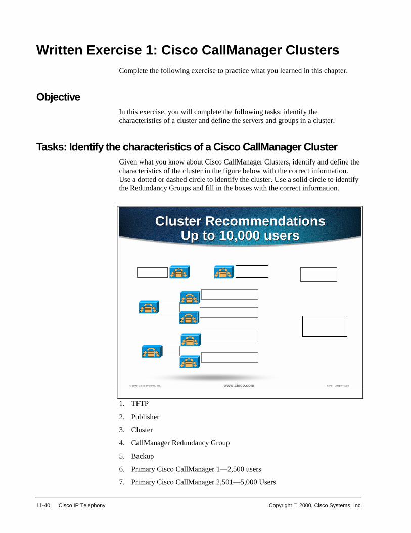
11-40 Cisco IP Telephony Copyright 2000, Cisco Systems, Inc.
Written Exercise 1: Cisco CallManager Clusters Complete the following exercise to practice what you learned in this chapter.
Objective In this exercise, you will complete the following tasks; identify the characteristics of a cluster and define the servers and groups in a cluster.
Tasks: Identify the characteristics of a Cisco CallManager Cluster Given what you know about Cisco CallManager Clusters, identify and define the characteristics of the cluster in the figure below with the correct information. Use a dotted or dashed circle to identify the cluster. Use a solid circle to identify the Redundancy Groups and fill in the boxes with the correct information.
© 1999, Cisco Systems, Inc. www.cisco.com CIPT—Chapter 12-6
Cluster RecommendationsUp to 10,000 users
Cluster RecommendationsUp to 10,000 users
1. TFTP
2. Publisher
3. Cluster
4. CallManager Redundancy Group
5. Backup
6. Primary Cisco CallManager 1—2,500 users
7. Primary Cisco CallManager 2,501—5,000 Users

Copyright 2000, Cisco Systems, Inc. Cisco CallManager Architecture 11-41
8. Primary Cisco CallManager 5,001—7,500 Users
9. Primary Cisco CallManager 7,501—10,000 Users
Completion Criteria You have completed the exercise when you have circled the cluster and redundancy group and identified the clustered components.

11-42 Cisco IP Telephony Copyright 2000, Cisco Systems, Inc.
Summary This section summarizes the concepts you learned in this chapter.
© 2000, Cisco Systems, Inc. www.cisco.com CIPT v 2.0—12-52
SummarySummary
• Clustering offers many scalable options thatcan handle a maximum of 10,000 users percluster.
• All changes to the database need to be madein the publisher. The subscribers will checkwith the publisher to get updates if there areany.
• N + 1 redundancy for Cisco IP telephonydevices are configured and each device canhave a primary, secondary, and tertiary CiscoCallManager
Cisco CallManager clustering offers a variety of scalable solutions. Each cluster can handle a maximum of 10,000 users that is done with a maximum of 2,500 users per CallManager and six CallManagers per cluster.
In a Cisco CallManager cluster the database relationship is a SQL publisher/subscriber relationship. All changes to the database need to be made in the publisher and the subscribers will check with the publisher to get updates if there are any.
N + 1 redundancy for Cisco IP telephony devices are configured and each device can have a primary, secondary, and tertiary Cisco CallManager.

Copyright 2000, Cisco Systems, Inc. Cisco CallManager Architecture 11-43
Review Questions Answer the following questions.
© 2000, Cisco Systems, Inc. www.cisco.com CIPT v 2.0—12-53
Review QuestionsReview Questions
1. What are the two intra-clustercommunications?
2. What is the relationship between publisher andsubscriber databases in a cluster?
3. Cisco IP telephony devices has a prioritizedlist of how many CallManagers?
Q1) Cisco CallManager clusters provide scalability and redundancy. What are the two primary intra-cluster communications?
Q2) Cisco CallManager uses SQL database with Service Pack 2. What is the relationship between the publisher and subscriber database when looking up information?
Q3) Cisco IP telephony devices need redundancy in a Cisco CallManager cluster. How many Cisco CallManagers can a device have in its prioritized list?

12
Overview As with any architecture, Cisco AVVID relies upon a strong and stable foundation. This foundation is built upon the Cisco multiprotocol routers and Catalyst Multilayer LAN switches that are used as building blocks for enterprise networks. This section discusses how to prepare your current LAN infrastructure for a successful AVVID deployment. The concepts and implementation techniques discussed apply equally to a campus of any size; be it a HQ environment with tens of thousands of users to a small branch with less than a hundred users. What will differ are the actual components/platforms selected and the level of detail in terms of scalability, network availability, and functionality.
The following key areas are discussed in this section.
■ Objectives
■ Visual Objectives
■ Network Infrastructure
■ High Availability
■ IP Addressing
■ Quality of Service (QoS)
■ Power to IP Phones
■ Power Protection Strategies
■ Written Exercises
■ Summary
■ Review Questions
■ Laboratory Exercise

12-2 Cisco IP Telephony Copyright 2000, Cisco Systems, Inc.
Objective This section lists the chapter objectives.
? 2000, Cisco Systems, Inc. www.cisco.com CIPT v2.0? 3-3
ObjectivesObjectives
Upon completion of this chapter, you willbe able to perform the following tasks:• Identify well built network infrastructures• Identify and describe IP addressing options• Select the correct commands from a list of
five that allow for VLAN ID• Identify the QoS issues and a way to ensure
voice is a priority over data
Upon completion of this chapter, you will be able to perform the following tasks:
■ Given a set of network topologies, you will be able to identify and select a well-built network infrastructure.
■ Given a case scenario for IP addressing, you will be able to identify and select the best option for IP addressing within the case scenario’s network.
■ Given a list of Catalyst switch commands, you will be able to identify the correct command that enables VLAN ID.
■ Given a converged voice/data network, you will be able to list the QoS issues and commands to ensure voice is a priority over data.

Copyright 2000, Cisco Systems, Inc. Campus Infrastructure 12-3
Visual Objective This section shows the visual objective of a successful AVVID deployment.
© 2000, Cisco Systems, Inc. www.cisco.com CIPT v2.0—12-4
AVVID Deployment ModelAVVID Deployment Model
PSTN
IP WANFrame Relay or ATM or Leased
Layer 3 Switched Campus Backbone
To PSTN
Server Farm CallManager
Voice-Enabled Router Gateway
Catalyst Switch
Catalyst Switch
Departments Buildings
V
V V
V
The following sections in this chapter provide a brief description of the concepts and techniques used to prepare for AVVID deployment.

12-4 Cisco IP Telephony Copyright 2000, Cisco Systems, Inc.
Network Infrastructure This section describes the network infrastructure you need to build an IP telephony system.
? 2000, Cisco Systems, Inc. www.cisco.com CIPT v2.0? 3-5
Switched 10/100 NetworkInfrastructure
Switched 10/100 NetworkInfrastructure
To build an IP telephony system end to end requires an IP Infrastructure based on layer 2/3 switches and routers. Switched connection to the desktop is a must for IP telephony. Ensure that the end-points are connected using switched 10/100 ports.
Note Plugging in shared hubs to the switch for device connectivity via these hubs is not recommended and may interfere with the correct operation.
IP phones available from Cisco provide a model of connectivity whereby PCs can be plugged into the phones which in turn are connected to the switch port. The phone has the necessary electronics to preserve the switched connectivity model for the PC. It has a three port switch inside that ensures quality of service for both the IP phone and downstream PC.
When using the Cisco IP 7960 Phone, separate VLANs can be configured for the phone and PC connected to the phone.
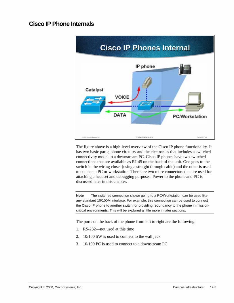
Copyright 2000, Cisco Systems, Inc. Campus Infrastructure 12-5
Cisco IP Phone Internals
? 2000, Cisco Systems, Inc. www.cisco.com CIPT v2.0? 3-6
Cisco IP Phones InternalCisco IP Phones Internal
The figure above is a high-level overview of the Cisco IP phone functionality. It has two basic parts; phone circuitry and the electronics that includes a switched connectivity model to a downstream PC. Cisco IP phones have two switched connections that are available as RJ-45 on the back of the unit. One goes to the switch in the wiring closet (using a straight through cable) and the other is used to connect a PC or workstation. There are two more connectors that are used for attaching a headset and debugging purposes. Power to the phone and PC is discussed later in this chapter.
Note The switched connection shown going to a PC/Workstation can be used like any standard 10/100M interface. For example, this connection can be used to connect the Cisco IP phone to another switch for providing redundancy to the phone in mission-critical environments. This will be explored a little more in later sections.
The ports on the back of the phone from left to right are the following:
1. RS-232—not used at this time
2. 10/100 SW is used to connect to the wall jack
3. 10/100 PC is used to connect to a downstream PC

12-6 Cisco IP Telephony Copyright 2000, Cisco Systems, Inc.
High Availability This section describes the prerequisite for voice networking, which is high availability. Cisco AVVID is a distributed architecture that is inherently available and scalable. The ability to seamlessly provision additional capacity for infrastructure, services, and applications is a unique benefit of the architecture.
In contrast to the PBX model, the world of converged networking depicts a scenario where availability is designed into a distributed system rather than a box. Redundancy is available in the individual hardware components for services such as power and supervisor modules. Network redundancy is, however, achieved with a combination of hardware, software, and intelligent network design practices.

Copyright 2000, Cisco Systems, Inc. Campus Infrastructure 12-7
Typical Enterprise Network
? 2000, Cisco Systems, Inc. www.cisco.com CIPT v2.0? 3-7
DistributionDistributionLayer 3Layer 3
CoreCoreLayer 3Layer 3
AccessAccessLayer 2Layer 2
WANWAN InternetInternet PSTNPSTN
DistributionDistributionLayer 3Layer 3
AccessAccessLayer 2Layer 2
Server FarmServer Farm
Typical Enterprise NetworkTypical Enterprise Network
In the above diagram, network redundancy is achieved at many levels. Physical connections exist from the edge devices where IP telephones and PCs are attached to two spatially diverse aggregation devices. Should an aggregation device fail, or connectivity is lost for any reason (such as fiber cut or power outage), cut over of traffic to the other device is possible. Clusters of Cisco CallManagers can be provisioned to provide resilient call control; should any device within the cluster fail, the other servers pick up the load.
Advanced Layer 3 protocols such as Hot Standby Routing Protocol (HSRP) or fast converging routing protocols such as Open Shortest Path First (OSPF) and Enhanced Interior Gateway Routing Protocol (EIGRP) can be used to provide optimum network layer convergence around failures.
Multicast routing can be used to optimize traffic that is required at many locations. The availability of advance multicast routing protocols such as Protocol Independent Multicast (PIM) ensure these services can be deployed efficiently.
Moving down the protocol stack, advanced tools are also available for the MAC layer, Layer 2. Tunable spanning-tree parameters and the ability to supply a spanning tree per virtual LAN (VLAN) allow fast convergence. Value-added features such as uplink-fast and backbone-fast allow intelligently designed networks to further optimize network convergence.
A big part in ensuring successful deployment comes from the fact that the underlying network is highly available. This translates to redundancy, resiliency, and fast convergence.

12-8 Cisco IP Telephony Copyright 2000, Cisco Systems, Inc.
For a more detailed discussion on this subject, please refer to the design guide(s) at:
http://www.cisco.com/warp/partner/synchronicd/cc/sol/mkt/ent/ndsgn/highd_wp.htm
http://wwwin.cisco.com/cmc/cc/sol/mkt/ent/cmps/gcnd_wp.htm
In addition, please take a look at the results of an independent study done by Ziff-Davis, exploring the redundancy/resiliency analysis in a network using Cisco switches and routers at:
http://www.zdnet.com/zdtag/whitepaper/campuslan.pdf

Copyright 2000, Cisco Systems, Inc. Campus Infrastructure 12-9
Physical Topologies and Connectivity Options
? 2000, Cisco Systems, Inc. www.cisco.com CIPT v2.0? 3-8
Connectivity OptionsConnectivity Options
Single Port
MultiplePorts
Soft Phone
1
2
3
Cisco IP phones and PC/workstations can be connected to the network in three different ways.
Cisco IP phones can be connected to the switch with data device (PC or workstation) connected to the switched Ethernet port available in the back of Cisco IP phone. This is reflected as option 1 in the figure above. This is the most common connectivity option that will be used. The advantage of this option is that it uses a single port on the switch and provides switched connectivity to both the devices. Also no changes to the cabling plant are required if the phone is line powered. The drawback is that if the IP phone goes down, then the PC also goes down. This arrangement aids in rapid deployment with minimal modifications to the existing environment.
The second method shown above shows the phone and PC connected to different switch ports. Although this option doubles the switch port count for every user, it provides a level of redundancy for the user. If the phone goes down, the PC does not get affected and vice-versa. Also if the phone and PC are connected to ports on different modules then another layer of redundancy is achieved, which protects one of the devices if a module goes down.
The third option shown above is a little unique in that the phone is not a hardware device but a JTAPI application running on the user’s PC. It is called a soft phone. This option may appeal to some specific environments where the need for a separate handset is minimal.

12-10 Cisco IP Telephony Copyright 2000, Cisco Systems, Inc.
IP Addressing This section describes the options used to extend IP addressing to accommodate IP phones.
? 2000, Cisco Systems, Inc. www.cisco.com CIPT v2.0? 3-9
IP Address PlanIP Address Plan
IP phones need addresses too!• Configure phones statically or use DHCP
Address space options:• Double current address space• Phones on separate subnets• Secondary addressing per segment• Use of RFC addresses for oice? subnet
Phones don work across NAT/PAT/firewall boundaries today
Each IP phone needs an IP address and associated information like subnet mask, default gateway, and so forth. This information can be provided by statically configuring it on the phone or it can be provided via DHCP. In this section we will discuss various options available for extending the IP addressing plan to accommodate IP phones.
To meet this requirement, there are a few options:
1. Provide an IP address in the same subnet as the existing data device
2. Redo the entire IP addressing plan for the organization
3. Create a new subnet and use it for IP phones
All of the above mentioned options could be implemented using DHCP or static configuration.
Since every phone needs an IP address in addition to the data device (PC or workstation), it means that an organization’s requirements for IP addresses has doubled. Although this concept is very straightforward, a significant number of customers have IP subnets with more than 50% of their subnet addresses already in use/allocated/assigned. This would mean that option 1 mentioned previously couldn’t be implemented. If new addresses have to be assigned for IP phones out of the existing subnets, then customers would have to renumber their IP addressing plan. This is option 2 as mentioned previously and may not always be feasible. One solution is to put the IP phones on a separate IP subnet. This solution maps to option 3, soft phone.

Copyright 2000, Cisco Systems, Inc. Campus Infrastructure 12-11
The new subnet could be in a registered address space or in private address space like Network 10.0.0.0. Now, the PC/workstation could be on a regular data subnet and the phone would be on the voice subnet. In order to minimize the configuration required on the phone, it is better for the phone to learn as much information dynamically as possible. This includes the separate voice subnet for the phone. So when the phone powers up, it should get its voice subnet automatically and then the phone can send a DHCP request on that subnet for getting an IP address.
In order to understand the automated mechanism of getting this voice subnet to the phone from the switch at power up, we need to understand the enhancements done in Cisco Discovery Protocol (CDP).
Phones cannot work across Network Address Translation (NAT) or firewall boundaries today.

12-12 Cisco IP Telephony Copyright 2000, Cisco Systems, Inc.
CDP Enhancements CDP is a device discovery protocol that runs on all Cisco equipment. Each device sends periodic messages to a multicast address and listens to the periodic messages sent by others. This is done to learn about neighboring devices and determine whether their interfaces are up or down and other relevant information like layer 2/3 protocols used, protocol addresses, native VLAN of the interconnected ports, duplex, and so forth. CDP is also used to send some layer 2/3 protocol specific messages.
There is a level of interaction between the Cisco IP phone and the Catalyst switch to make it plug and play. Cisco IP phones support CDP. This makes it possible for the switch to know that an IP phone is connected to it and vice versa.
© 2000, Cisco Systems, Inc. www.cisco.com CIPT v2.0—12-10
New CDP FieldsNew CDP Fields
• Voice VLAN ID (VVID)—Communicating Voice VLAN ID (Voice subnet) to the phone
• Trigger Field—Soliciting response from the connected device
• Power Field—Required for getting exact power requirement from the phone
Three new fields have been added to CDP. They are:
■ Voice VLAN ID (VVID) field for communicating the voice VLAN ID (voice subnet) to the IP phone.
■ Trigger field for soliciting a response from the connected device—used to force a response from the connected device. Under normal circumstances, a device sends CDP messages at one minute (configurable) intervals. But if an IP phone comes up within this interval, it cannot receive its VVID. In this case the IP phone will issue a trigger in the CDP message it sends to the switch. This will force the switch to respond with a VVID.
■ Power—required field for getting the exact power requirement from the phone.

Copyright 2000, Cisco Systems, Inc. Campus Infrastructure 12-13
A VLAN at Layer 2 maps to a subnet at Layer 3 in terms of a broadcast domain, such that a VLAN equals a subnet. The desired functionality is that when an IP phone is plugged into the switch, it should automatically get its specific VLAN ID (voice VLAN or voice subnet) from the switch if one is configured. If not, the IP phone will reside in the native VLAN (data subnet) of the switch.
A new concept called Voice VLAN ID (VVID) is introduced in CatOS starting with release 5.5. This is the VLAN (subnet) that will be given to the IP phone by the switch inside the CDP message. The prerequisite is an IP phone-specific VLAN configured on the switch. Switch configuration details will be shown, with an example, later on in the section.
When an IP phone is powered by inline power, it is automatically provided 10W of electricity. Since the switch doesn’t know exactly how much power the IP phone requires, the IP phone can send a CDP message, using the Power Consumption field set to its own specific requirements. The switch then adjusts the resource accordingly.

12-14 Cisco IP Telephony Copyright 2000, Cisco Systems, Inc.
Voice VLAN ID (VVID) and Port VLAN ID (PVID)
? 2000, Cisco Systems, Inc. www.cisco.com CIPT v2.0? 3-10
VVID and PVIDVVID and PVID
Voice VLAN ID = VVIDPort VLAN ID = PVID
The new voice VLAN is referred to as Auxiliary VLAN in the CatOS CLI for configuration purposes. Traditionally in the switched world, we understand data VLANs. This is typically where all the data devices reside. The new auxiliary VLAN is used to collectively represent other types of devices. Today that device is an IP phone and, hence, this could be thought of as a voice VLAN. In the future if there are other types of non-data devices, they will fall in the auxiliary VLAN.
The idea is that these non-data devices (IP phone) will reside in a separate VLAN (auxiliary VLAN), which will make it easier for customers to automate the process of deploying the phones. Just like data devices come up and reside in the native VLAN (also referred to as default VLAN) of the switch, phones will come up in the auxiliary VLAN if the switch has been configured as such. When the phone powers up, it communicates with the switch via CDP. The switch will provide the phone with the appropriate VLAN ID that was configured. This is known as the Voice VLAN ID or VVID. This is very analogous to the data VLAN ID that is known as Port VLAN ID or PVID.
To summarize, data devices reside in the native VLAN (or default VLAN) of the switch and phones will reside in the auxiliary VLAN on the switch. Data device VLAN (data subnet) is referred to as PVID and Phone VLAN (voice subnet) is referred to as VVID.
This concept has quite a few merits. Besides making it very plug and play, it also aids in applying advanced QoS concepts on a per VLAN (subnet) basis. The data subnet may have different QoS settings and voice subnet may have more different QoS settings.

Copyright 2000, Cisco Systems, Inc. Campus Infrastructure 12-15
VVID Configuration
? 2000, Cisco Systems, Inc. www.cisco.com CIPT v2.0? 3-11
VVID ConfigurationVVID Configuration
The VVID is configured in the CatOS version 5.5 using the syntax set port auxiliaryvlan <mod/port>.
In this example, the voice VLAN (VVID) has been set to the value 222 for ports 2/1 through 2/3. When the phone powers up, the switch will instruct it to be in VLAN 222. This command can be used to set the VVID on a per port basis, range of ports, or for an entire module.

12-16 Cisco IP Telephony Copyright 2000, Cisco Systems, Inc.
VVID Status
? 2000, Cisco Systems, Inc. www.cisco.com CIPT v2.0? 3-12
VVID StatusVVID Status
Once the phone gets it voice subnet, it will issue a DHCP request on that subnet.
Listed below are some important steps in the process when an IP phone is plugged into the network to preparing to make phone calls. Assuming that the IP phone is already powered up:
1. IP phone will begin a CDP exchange with the switch. It will issue a trigger CDP to force a response from the switch that will contain its Voice VLAN ID (VVID) or voice subnet.
2. By default, IP phone is configured for DHCP. It will issue a DHCP request on the voice subnet it got in step 1 above. In general, this is the recommended mode of operation. Static addressing can be supplied to the telephone, and you can enter the IP address manually, but this would prevent mobility and increase requirements of technical personnel.
3. IP phone will get a response from the DHCP server in the network. As part of that DHCP response, an IP address is supplied to the telephone. It is also possible to supply the address of the TFTP server, from which the telephone will get its configuration. Once again, the TFTP server address could be specified manually but this would limit adds, moves, and changes and remove some of the benefits. This TFTP server address can be given as part of the DHCP response. This can be done several ways by configuring option 066 or custom option 150 on the DHCP server and specifying the address of the TFTP server. The Cisco DHCP server supports this feature.

Copyright 2000, Cisco Systems, Inc. Campus Infrastructure 12-17
4. The IP phone will contact the TFTP server and will receive the address of the CallManager. Up to three CallManagers can be specified in the list that the IP phone will get. This allows for redundancy in case the first CallManager in the list is not available. The phone will now contact the CallManager and register itself.
5. After the IP phone receives its configuration file, the IP phone will attempt to register with the Cisco CallManager. If the firmware version in the IP phone is correct, the registration will complete. If the firmware version in the phone is not correct the IP phone will TFTP for a new firmware version, then attempt to register with the Cisco CallManager. IP phone will receive a number (referred to as DN number) from the CallManager per configuration. This is the number that will be used for calling the particular IP phone.
6. Now the IP phone is ready to make calls.
Note This process when an IP phone is plugged into the network preparing to make phone calls takes about 90 seconds. To speed it up, turn on portfast and turn off port channeling as well as trunking. This reduces the time taken to about 30 seconds.

12-18 Cisco IP Telephony Copyright 2000, Cisco Systems, Inc.
Sample IP Addressing Plan
© 2000, Cisco Systems, Inc. www.cisco.com CIPT v2.0—12-14
Sample IP Addressing Plan
171.68.249.101 171.68.249.100
IP phone + PC on IP phone + PC on separate switch portsseparate switch ports
Real IP addressesReal IP addresses
171.68.249.100
171.68.249.101
Real IP addressesReal IP addresses
IP phone + PC on IP phone + PC on same switch portssame switch ports
171.68.249.100
IP phone + PC shareIP phone + PC sharethe same devicethe same device
(soft phone)(soft phone)
Real IP addressesReal IP addresses
10.1.1.1
171.68.249.100
IP phone uses “10.0.0.0” IP phone uses “10.0.0.0” networknetwork
IP phone + PC on IP phone + PC on same switch portssame switch ports
171.68.249.10010.1.1.1
IP phone uses IP phone uses “10.0.0.0” network“10.0.0.0” network
IP phone + PC on IP phone + PC on separate switch portsseparate switch ports
To summarize, the recommendations for IP addressing are:
■ Continue to use existing addressing for data devices (PC’s, workstations, and so forth)
■ Add IP phones with DHCP as the mechanism for getting addressees
■ If subnets are available in existing address space then use them for IP phones
■ If not, then use private addressing (Network 10 or Network 172.16 – 172.20)

Copyright 2000, Cisco Systems, Inc. Campus Infrastructure 12-19
Quality of Service (QoS) This section describes the need for campus QoS.
In a converged environment, all traffic types travel over a single transport infrastructure. In addition, all traffic types are not same. Voice is bursty, slightly loss tolerant, and latency sensitive. Data on the other hand is well behaved (fixed bandwidth), has a little tolerance to loss, but is latency insensitive. The challenge is in providing the required level of service for these individual traffic types.
? 2000, Cisco Systems, Inc. www.cisco.com CIPT v2.0? 3-14
Avoiding loss, delay,and delay variation (jitter)
WANRouter
MultilayerCampus
MultilayerCampus
Router
Domains of QoSConsideration
Domains of QoSConsideration
CallManagerCallManager
Campus
Voice Enabled InfrastructureVoice Enabled Infrastructure
WAN Edge WAN Backbone
If you are running both voice and data on a common network then you need to employ proper tools to ensure that the delay and loss parameters of voice traffic are satisfied. The tools that allow you to ensure the required quality of service are available as features in phones, switches, and routers.
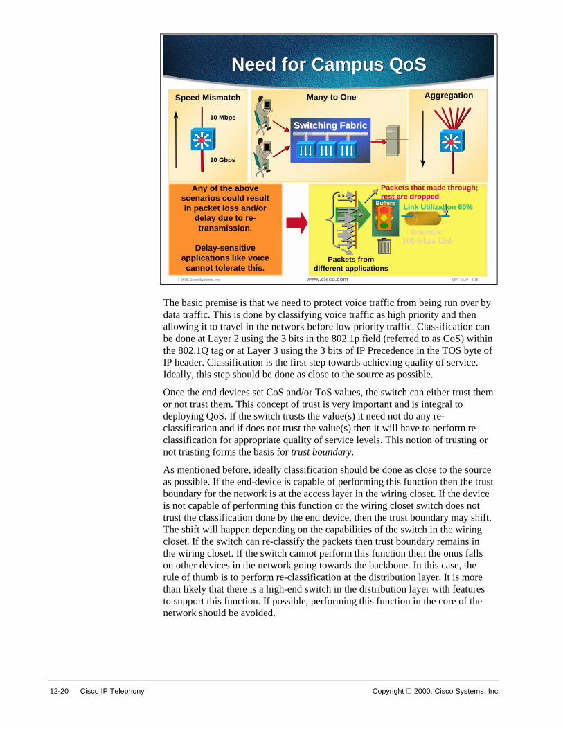
12-20 Cisco IP Telephony Copyright 2000, Cisco Systems, Inc.
? 2000, Cisco Systems, Inc. www.cisco.com CIPT v2.0? 3-15
Need for Campus QoSNeed for Campus QoSAggregationSpeed Mismatch
10 Mbps
10 Gbps
Switching FabricSwitching Fabric
Many to One
Link Utilization 60%Link Utilization 60%
Example: Example: 100 Mbps Link100 Mbps Link
Packets fromdifferent applications
Packets that made through; Packets that made through; rest are droppedrest are dropped
BuffersBuffers
Any of the abovescenarios could resultin packet loss and/or
delay due to re-transmission.
Delay-sensitiveapplications like voicecannot tolerate this.
The basic premise is that we need to protect voice traffic from being run over by data traffic. This is done by classifying voice traffic as high priority and then allowing it to travel in the network before low priority traffic. Classification can be done at Layer 2 using the 3 bits in the 802.1p field (referred to as CoS) within the 802.1Q tag or at Layer 3 using the 3 bits of IP Precedence in the TOS byte of IP header. Classification is the first step towards achieving quality of service. Ideally, this step should be done as close to the source as possible.
Once the end devices set CoS and/or ToS values, the switch can either trust them or not trust them. This concept of trust is very important and is integral to deploying QoS. If the switch trusts the value(s) it need not do any re-classification and if does not trust the value(s) then it will have to perform re-classification for appropriate quality of service levels. This notion of trusting or not trusting forms the basis for trust boundary.
As mentioned before, ideally classification should be done as close to the source as possible. If the end-device is capable of performing this function then the trust boundary for the network is at the access layer in the wiring closet. If the device is not capable of performing this function or the wiring closet switch does not trust the classification done by the end device, then the trust boundary may shift. The shift will happen depending on the capabilities of the switch in the wiring closet. If the switch can re-classify the packets then trust boundary remains in the wiring closet. If the switch cannot perform this function then the onus falls on other devices in the network going towards the backbone. In this case, the rule of thumb is to perform re-classification at the distribution layer. It is more than likely that there is a high-end switch in the distribution layer with features to support this function. If possible, performing this function in the core of the network should be avoided.

Copyright 2000, Cisco Systems, Inc. Campus Infrastructure 12-21
? 2000, Cisco Systems, Inc. www.cisco.com CIPT v2.0? 3-17
Frame Tagged with PVID andVVID
Tagged 802.1q
Untagged 802.3
An access port able to handle 2 VLANsNative VLAN (PVID) & Auxiliary VLAN (VVID)Hardware set to dot1q trunk
Cisco IP phones have the ability to mark voice packets as high priority using CoS as well as ToS. By default, the phone will send 802.1Q tagged packets with the CoS and ToS set to a value of 5.
Packets from the phone are sent as tagged frames with the .1p fields set to 5. Frames from the PC are sent untagged as shown in the figure above.
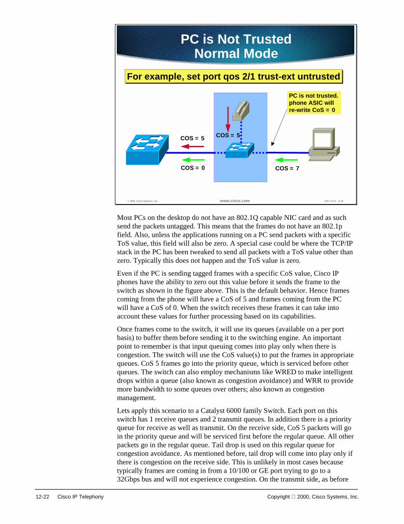
12-22 Cisco IP Telephony Copyright 2000, Cisco Systems, Inc.
? 2000, Cisco Systems, Inc. www.cisco.com CIPT v2.0? 3-18
PC is Not TrustedNormal Mode
COS = 5
COS = 0
COS = 5
COS = 7
PC is not trusted.phone ASIC willre-write CoS = 0
For example, set port qos 2/1 trust-ext untrustedFor example, set port qos 2/1 trust-ext untrusted
Most PCs on the desktop do not have an 802.1Q capable NIC card and as such send the packets untagged. This means that the frames do not have an 802.1p field. Also, unless the applications running on a PC send packets with a specific ToS value, this field will also be zero. A special case could be where the TCP/IP stack in the PC has been tweaked to send all packets with a ToS value other than zero. Typically this does not happen and the ToS value is zero.
Even if the PC is sending tagged frames with a specific CoS value, Cisco IP phones have the ability to zero out this value before it sends the frame to the switch as shown in the figure above. This is the default behavior. Hence frames coming from the phone will have a CoS of 5 and frames coming from the PC will have a CoS of 0. When the switch receives these frames it can take into account these values for further processing based on its capabilities.
Once frames come to the switch, it will use its queues (available on a per port basis) to buffer them before sending it to the switching engine. An important point to remember is that input queuing comes into play only when there is congestion. The switch will use the CoS value(s) to put the frames in appropriate queues. CoS 5 frames go into the priority queue, which is serviced before other queues. The switch can also employ mechanisms like WRED to make intelligent drops within a queue (also known as congestion avoidance) and WRR to provide more bandwidth to some queues over others; also known as congestion management.
Lets apply this scenario to a Catalyst 6000 family Switch. Each port on this switch has 1 receive queues and 2 transmit queues. In addition there is a priority queue for receive as well as transmit. On the receive side, CoS 5 packets will go in the priority queue and will be serviced first before the regular queue. All other packets go in the regular queue. Tail drop is used on this regular queue for congestion avoidance. As mentioned before, tail drop will come into play only if there is congestion on the receive side. This is unlikely in most cases because typically frames are coming in from a 10/100 or GE port trying to go to a 32Gbps bus and will not experience congestion. On the transmit side, as before

Copyright 2000, Cisco Systems, Inc. Campus Infrastructure 12-23
CoS 5 frames will go in the priority queue and will be serviced first. Remaining frames will go in regular queues. CoS values 0,1,2, and 3 will go in Lo regular queue and CoS values 4,6, and 7 will go in Hi regular queue. In addition, within each queue we can use WRED to make intelligent drops based on the CoS value and what percentages of buffers are full. Finally, the Hi regular queue and Lo regular queue will be serviced based on the WRR configuration. One can configure it to say they will be serviced in 25 to 75 ratios. This is done after the priority queue has been emptied out.
All the values for WRED, WRR, and queue sizes are configurable.
Catalyst 6000 family switches also support the notion of trusted and not trusted. The switch can be configured to do this on a per port basis. From the CLI use the following command:
set port qos <mod/ports.> trust <untrusted|trust-cos|trust-ipprec|trust-dscp>
This command allows you to configure the trust state as well as to specify to trust CoS or ToS (trust-ipprec) or DSCP (DS Codepoint) which is an emerging Layer 3 standard under IETF’s Differentiated Services working group.
So far we have talked about the voice traffic that comes in as CoS 5 and PC traffic is zeroed out if there is any tag.

12-24 Cisco IP Telephony Copyright 2000, Cisco Systems, Inc.
? 2000, Cisco Systems, Inc. www.cisco.com CIPT v2.0? 3-19
PC is Trusted
COS = 5
COS = 7
COS = 5
COS = 7
Trusted
e.g. set port qos 2/1 trust-ext trust-cose.g. set port qos 2/1 trust-ext trust-cos
There may be times when we may want to trust the PC CoS (if sending tagged packets) or give it a value other than zero. This can be achieved on Catalyst switches as well.
This is achieved by extending the trust out to the PC. Use the following command to extend trust out to the PC:
Set port qos 2/1 trust-ext trust-cos

Copyright 2000, Cisco Systems, Inc. Campus Infrastructure 12-25
? 2000, Cisco Systems, Inc. www.cisco.com CIPT v2.0? 3-20
PC is Not Trusted
COS = 5
COS = 2
COS = 5
COS = 7
PC is not trusted.Phone ASIC will re-write CoS based onswitch configuration
e.g. extended COS = 2
For example, set port qos 2/1 cos-ext 2For example, set port qos 2/1 cos-ext 2
When a PC is not trusted extend a specific CoS value to the PC traffic. The command used to extend a specific CoS value to the PC traffic is:
Set port qos 2/1 cos-ext 2
All of the above configurations shown along with the individual figures can be done for any of the Catalyst switches that use CatOS.
So far we have discussed the Quality of Service Implementation model at Layer 2 using the 802.1p bits within the 802.1Q tag. This technique provides the desired results at Layer 2. When traffic has to cross a Layer 3 boundary, then it becomes imperative to implement these mechanisms using Layer 3 parameters like the 3 IP precedence bits (commonly referred to as ToS) or the new emerging DSCP parameter that uses the six most significant bits within the ToS byte of the IP header. Traffic crosses Layer 3 boundaries when packets need to cross subnets. Layer 3 switches or routers facilitate this. Traffic also crosses Layer 3 boundaries when packets need to go out of the campus network onto the WAN via edge routers. When this happens, a Layer 2 classification does not help. We need Layer 3 classification for achieving the desired level of QoS.
All of the QoS techniques employed by the routers (including the very important WAN QoS) rely on Layer 3 classification. This is can be achieved by using the appropriate platforms in the campus. Beginning with the IP phones, we already have packets presented to the switch with CoS=ToS=5. This Layer 3 classification is preserved even if the packets travel all the way through to the WAN edge router where the Layer 2 header is removed. So, if the trust boundary is at the source (IP phone) then voice traffic will have the ToS bits set to 5 and will be presented to the network devices for appropriate treatment. WAN routers can use this classification to employ any of the queuing techniques. If the trust boundary is not at the source and packets need to be re-classified, then the device performing this function should be capable of doing it at Layer 3 before it can cross a Layer 3 boundary.

12-26 Cisco IP Telephony Copyright 2000, Cisco Systems, Inc.
Catalyst 6000 family switches equipped with the Policy feature Card (PFC) perform this function by default when the port is trusted. So if a packet comes in a trusted port with CoS equals 5, then the switch will take this value and re-write the ToS bits to make it equal to 5 as well. No additional configuration is needed. If the port is un-trusted, then the packet gets a default CoS at the input port. Now we can configure a QoS access-list on the switch and re-write the ToS to a desired value based on some matching criteria; for example:
set qos acl ip TEST dscp 40 10.1.1.0 0.0.0.255 any
This command will set a ToS of 5 for all packets coming from subnet 10.1.1.0 and going anywhere.
In addition QoS access-lists can include L4 information as well to classify individual applications. Catalyst 6000 switches are also capable of policing traffic based on L3 addresses and L4 port numbers. For example, you can police individual http flow to 1M and aggregate all http flows to 25M.
All of these QoS features on Catalyst 6000 switches provide a high degree of flexibility.

Copyright 2000, Cisco Systems, Inc. Campus Infrastructure 12-27
? 2000, Cisco Systems, Inc. www.cisco.com CIPT v2.0? 3-16
Summary of QoS IssuesSummary of QoS Issues
• Classify and/or re-classify packets as close to the edge aspossible
• Make the access layer the trust boundary• If wiring closet switch does not have appropriate QoS hooks,
shrink trust boundary to distribution layer, no further• Use WRED for making intelligent packet drops• Use priority classification to expedite delay-sensitive traffic• Use WRR (if switch has multiple queues) in conjunction (or
otherwise) for servicing Hi queue more often• For very small offices with low user count and no QoS capable
switch, WAN edge can be the trust boundary
To summarize, try to maintain the trust boundary in the wiring closet. If need be, shrink it down to the distribution layer on a case by case basis and avoid shrinking it down to the core of the network. This is in line with the guidance provided earlier to keep the trust boundary as close to the source as possible.
Note The discussion above takes into consideration a 3-tier network model, which has proved to be a scalable architecture. If the network is small and the logical functions of distribution layer and core layer happen to be in the same device then, the trust boundary may reside in the core layer if it has to move from the wiring closet.

12-28 Cisco IP Telephony Copyright 2000, Cisco Systems, Inc.
The following figure illustrates some important points to note regarding Catalyst 6000 QoS functionality.
? 2000, Cisco Systems, Inc. www.cisco.com CIPT v2.0? 3-21
Notes about Catalyst 6000QoS Functionality
Notes about Catalyst 6000QoS Functionality
• By default, QoS is not enabled.
• By default, ports are not trusted.
• QoS configurations can be applied on a perport basis or on a per VLAN basis.
• Catalyst 6000 can map CoS to ToS in anysituation. Either by default, when the port istrusted, or by using the QoS access list.
By default, QoS is not enabled. Use set qos enable to turn on QoS.
By default, ports are not trusted. Use set port qos mod_num/port_num trust {untrusted | trust-cos | trust-ipprec | trust-dscp} to trust a port.
QoS configurations can be applied on a per port basis or on a per VLAN basis. This works very well for IP telephony deployments where phones are on a separate VLAN/subnet as discussed before in the IP addressing section.
The Catalyst 6000 can map CoS to ToS in any situation. Either by default, when the port is trusted, or by using the QoS access list.
If the trust boundary happens to be on a switch in the wiring closet that is not capable of re-classifying at Layer 3, then shrink the trust boundary to the distribution layer where it is more likely that a Layer 3 capable device will be present.
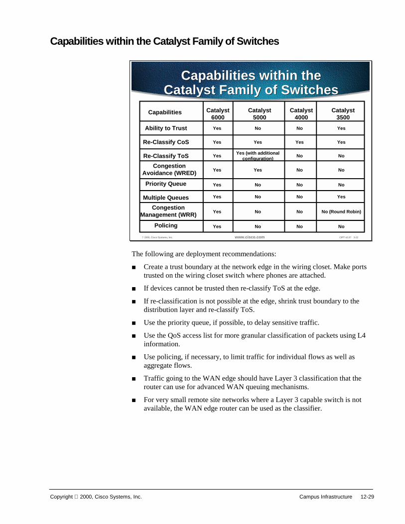
Copyright 2000, Cisco Systems, Inc. Campus Infrastructure 12-29
Capabilities within the Catalyst Family of Switches
? 2000, Cisco Systems, Inc. www.cisco.com CIPT v2.0? 3-22
Capabilities within theCatalyst Family of Switches
Capabilities within theCatalyst Family of Switches
Catalyst6000Yes
Yes
Yes
Yes
Yes
Yes
Yes
Yes
Catalyst3500
No (Round Robin)
Yes
Yes
Yes
No
No
No
No
Catalyst4000
Yes
No
No
No
No
No
No
No
Catalyst5000
Yes (with additionalconfiguration)
Yes
Yes
No
No
No
No
No
CongestionAvoidance (WRED)
Policing
CongestionManagement (WRR)
Re-Classify ToS
Multiple Queues
Re-Classify CoS
Priority Queue
Ability to Trust
Capabilities
The following are deployment recommendations:
■ Create a trust boundary at the network edge in the wiring closet. Make ports trusted on the wiring closet switch where phones are attached.
■ If devices cannot be trusted then re-classify ToS at the edge.
■ If re-classification is not possible at the edge, shrink trust boundary to the distribution layer and re-classify ToS.
■ Use the priority queue, if possible, to delay sensitive traffic.
■ Use the QoS access list for more granular classification of packets using L4 information.
■ Use policing, if necessary, to limit traffic for individual flows as well as aggregate flows.
■ Traffic going to the WAN edge should have Layer 3 classification that the router can use for advanced WAN queuing mechanisms.
■ For very small remote site networks where a Layer 3 capable switch is not available, the WAN edge router can be used as the classifier.

12-30 Cisco IP Telephony Copyright 2000, Cisco Systems, Inc.
Power to IP Phones The new Cisco IP phones support a variety of power options. This section explains how each of the available powering schemes work.
? 2000, Cisco Systems, Inc. www.cisco.com CIPT v2.0? 3-23
� Inline Power� Needs powered linecards for Catalyst switches� Uses pins 1, 2, 3, and 6 (same as Ethernet) for delivering ? 8V
� External Power
� Needs external power patch panel� Patch panel delivers ? 8V over pins 4, 5, 7, 8
� Wall Power
� Needs DC converter for connecting IP phone to wall outlet
3 Ways to Power IP Phones3 Ways to Power IP Phones
Combination of ways can be used for redundancy
The Cisco IP phone is connected to an Ethernet switch using up to 100m of UTP Category 5 cable. It has a standard 10/100 Base T Ethernet port for connection to the switch, and another for local connection to a PC/workstation.
There are three methods of powering the IP phones:
■ Inline Power
■ External Power Patch Panel
■ Wall Power
Solution 1: Inline Power This method uses pins 1,2,3, and 6 of the 4 pairs in a category 5 cable to transmit power (-48V DC) supplied by the switch. It is referred to as inline or sometimes as phantom power because the power signals travel over the same two pairs used to transmit Ethernet signals. This is done in such a way that the power signals are completely transparent to the Ethernet signals and do not interfere with its operation. This method needs the new power enabled line cards for the switch. Currently such a line card is available for the Catalyst 6000 family switches with plans to extend the functionality to other catalyst switches over time.
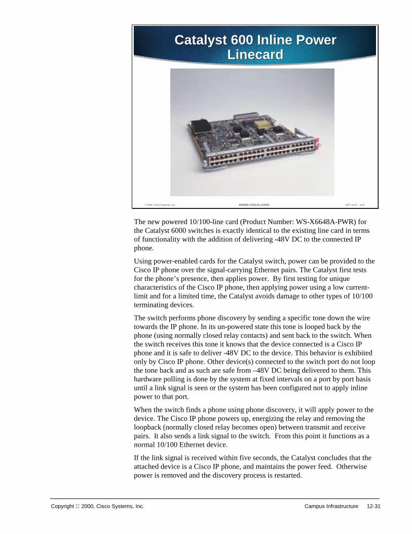
Copyright 2000, Cisco Systems, Inc. Campus Infrastructure 12-31
? 2000, Cisco Systems, Inc. www.cisco.com CIPT v2.0? 3-24
Catalyst 600 Inline PowerLinecard
Catalyst 600 Inline PowerLinecard
The new powered 10/100-line card (Product Number: WS-X6648A-PWR) for the Catalyst 6000 switches is exactly identical to the existing line card in terms of functionality with the addition of delivering -48V DC to the connected IP phone.
Using power-enabled cards for the Catalyst switch, power can be provided to the Cisco IP phone over the signal-carrying Ethernet pairs. The Catalyst first tests for the phone’s presence, then applies power. By first testing for unique characteristics of the Cisco IP phone, then applying power using a low current-limit and for a limited time, the Catalyst avoids damage to other types of 10/100 terminating devices.
The switch performs phone discovery by sending a specific tone down the wire towards the IP phone. In its un-powered state this tone is looped back by the phone (using normally closed relay contacts) and sent back to the switch. When the switch receives this tone it knows that the device connected is a Cisco IP phone and it is safe to deliver -48V DC to the device. This behavior is exhibited only by Cisco IP phone. Other device(s) connected to the switch port do not loop the tone back and as such are safe from –48V DC being delivered to them. This hardware polling is done by the system at fixed intervals on a port by port basis until a link signal is seen or the system has been configured not to apply inline power to that port.
When the switch finds a phone using phone discovery, it will apply power to the device. The Cisco IP phone powers up, energizing the relay and removing the loopback (normally closed relay becomes open) between transmit and receive pairs. It also sends a link signal to the switch. From this point it functions as a normal 10/100 Ethernet device.
If the link signal is received within five seconds, the Catalyst concludes that the attached device is a Cisco IP phone, and maintains the power feed. Otherwise power is removed and the discovery process is restarted.

12-32 Cisco IP Telephony Copyright 2000, Cisco Systems, Inc.
Once the Cisco IP phone is powered and responding, the phone discovery mechanism enters a steady state. Should the phone be removed, or the link interrupted, the discovery mechanism will start again. The port is checked every five seconds for a link packet, and in its absence, the test tone is generated.
The advantage of this mechanism is that power is supplied to the phone by the switch just like today’s telephony environment. It is entirely possible that only two pairs have been terminated out of the four available for the data run between wiring closet and the desktop location. The inline power method allows customers to use the existing cable plant without any modification for deploying IP telephony.
The inline power method requires CatOS 5.5 (or higher) running on the Catalyst Switch. This release of the software has all of the enhancements required for proper operation. In particular, it has all of the necessary commands to control the operation of the switch as far as delivering power is concerned. The switch has an option of either providing power through the power-enabled line card or not to do so even if it has the ability.
Each port on the switch can be configured via the CLI (or SNMP or a config file) to be in either Auto, or Off modes as defined in the following way:
■ Auto: Switch supervisor will tell the port to supply 48V to the phone only if it discovered the phone using the phone discovery mechanism that is, the Cisco IP phone discovered by the switch via the test tone in un-powered state. This is also the default behavior.
■ Off: Switch supervisor will instruct the port not to apply power even if it can and knows

Copyright 2000, Cisco Systems, Inc. Campus Infrastructure 12-33
? 2000, Cisco Systems, Inc. www.cisco.com CIPT v2.0? 3-26
Verifying Inline Power StatusVerifying Inline Power Status
Command: show port inlinepower <mod>|<mod/port>Output:
Default Inline Power allocation per port: 12.500 Watts (0.29 Amps @42V)Total inline power drawn by module 7: 37.80 Watts (0.90 Amps @42V)y module
5: 37.80 Watts ( 0.90Port InlinePowered PowerAllocated
Admin Oper Detected mWatt mA @42V----- ----- ------ -------- ----- --------7/1 auto off no 0 07/2 auto on yes 12600 3007/3 auto faulty yes 12600 3007/4 auto deny yes 0 07/5 on deny yes 0 07/6 on off no 0 07/7 off off no 0 0
The figure above shows the CLI output that provides detail on the actual power consumed.
This leads to an important area with respect to available system power. Current Cisco IP phone model 7960 consumes 5W. The switch system should be equipped with appropriate power supplies to accommodate the required number of phones.
Note The new 2500W Power Supply for Catalyst 6000 family switches need 220V. It will work with 110V but will deliver 1300W. In addition it needs 20A regardless of whether it is plugged into 110V or 220V. This means that wiring closets must have 220V available in our example case.
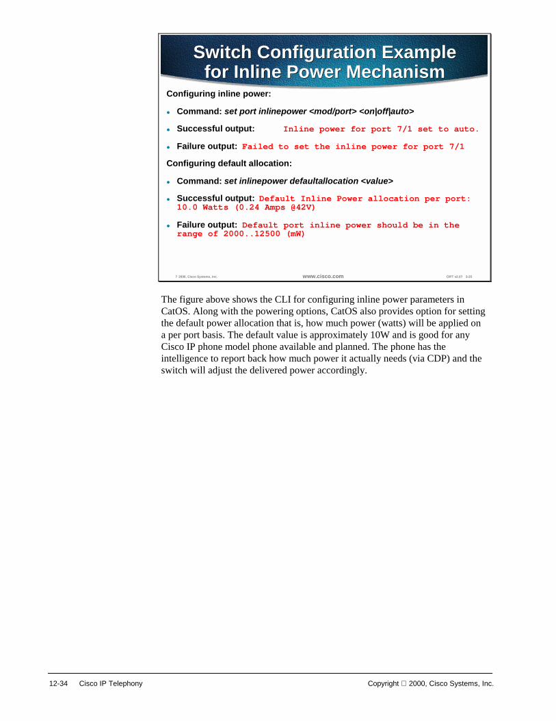
12-34 Cisco IP Telephony Copyright 2000, Cisco Systems, Inc.
? 2000, Cisco Systems, Inc. www.cisco.com CIPT v2.0? 3-25
Switch Configuration Examplefor Inline Power Mechanism
Switch Configuration Examplefor Inline Power Mechanism
Configuring inline power:
� Command: set port inlinepower <mod/port> <on|off|auto>
� Successful output: Inline power for port 7/1 set to auto.
� Failure output: Failed to set the inline power for port 7/1
Configuring default allocation:
� Command: set inlinepower defaultallocation <value>
� Successful output: Default Inline Power allocation per port:10.0 Watts (0.24 Amps @42V)
� Failure output: Default port inline power should be in therange of 2000..12500 (mW)
The figure above shows the CLI for configuring inline power parameters in CatOS. Along with the powering options, CatOS also provides option for setting the default power allocation that is, how much power (watts) will be applied on a per port basis. The default value is approximately 10W and is good for any Cisco IP phone model phone available and planned. The phone has the intelligence to report back how much power it actually needs (via CDP) and the switch will adjust the delivered power accordingly.

Copyright 2000, Cisco Systems, Inc. Campus Infrastructure 12-35
? 2000, Cisco Systems, Inc. www.cisco.com CIPT v2.0? 3-27
Inline Power Syslog MessagesInline Power Syslog Messages
Not enough power available:
%SYS-3-PORT_NOPOWERAVAIL:Device on port 5/12will remain unpowered
Link did not come up after powering on the port:
%SYS-3-PORT_DEVICENOLINK:Device on port 5/26powered but no link up
Faulty port power:
%SYS-6-PORT_INLINEPWRFLTY:Port 5/7 reportinginline power as faulty
CatOS has the ability to send syslog messages to the console (or any other place if so configured) indicating any deviations from the normal as shown in the figure above.
In addition the system also maintains power status on a per port basis. This can be checked using show port status.
The CatOS has three different values:
■ On: Power is being supplied by the port.
■ Off: Power is not being supplied by the port.
■ Power-Deny: System does not have enough power so the port does not supply power.
When the system is using dual supervisors, power management per port and phone status is synchronized between the active and standby supervisor. This is done on an on-going basis and is triggered with any change to the power allocation or phone status. All the high availability features designed in CatOS 5.5 and higher are useful in this scenario. The HA features are not affected in any way.
One last point on this subject is power protection schemes. This will be discussed in detail later on. Conceptually though, it is recommended that UPS (es) should be used for a higher degree of redundancy and availability.

12-36 Cisco IP Telephony Copyright 2000, Cisco Systems, Inc.
Solution 2: Cisco Patch Panel
? 2000, Cisco Systems, Inc. www.cisco.com CIPT v2.0? 3-28
Cisco Power Patch PanelCisco Power Patch Panel
If the switch does not have a power enabled 10/100-line card (Product Number: WS-PWR-PANEL) or one is not available for the switch, then a Cisco patch panel can be inserted in the wiring closet between the Ethernet switch and the Cisco IP phone. This device is also known as Cisco Power Patch Panel.
The patch panel has a 250W power supply and draws its power from an 110V AC source. It can accommodate 48 ports and is capable of supplying -48V to each of the 48 ports. At 5W per Cisco IP phone model 7960, it has enough power for all the 48 ports. A UPS is recommended for back up in the event of a power failure. The patch panel uses CDP as a discovery mechanism and sends power using Pins 4. 5, 7, and 8 to the phone.

Copyright 2000, Cisco Systems, Inc. Campus Infrastructure 12-37
? 2000, Cisco Systems, Inc. www.cisco.com CIPT v2.0? 3-29
Power Patch PanelConnectivity
Power Patch PanelConnectivity
1 3 5 472 4 6 48
1 3 5 472 4 6 48
Switch SideRJ-45
Phone SideRJ-45
2 pairs(4 wires)
4 pairs(8 wires)
In the figure above, the patch panel has two ports that correspond to one connection. One port goes to the switch side and the other goes to the phone side.
This arrangement of applying power to the phone utilizes all four pairs in the Category 5 cable. Unlike the inline method, Ethernet pairs do not carry power signals. The remaining pairs of Category 5 cable are used for delivering power from the patch panel.

12-38 Cisco IP Telephony Copyright 2000, Cisco Systems, Inc.
External Power through Patch Panel
? 2000, Cisco Systems, Inc. www.cisco.com CIPT v2.0? 3-30
External Power through PatchPanel
External Power through PatchPanel
As seen in the figure above, Pins 1, 2, 3, and 6 from the switch are patched straight through to Pins 1, 2, 3, and 6 coming from the phone. Pins 4, 5, 7, and 8 from the phone terminate at the patch panel (Ethernet has no use for Pins 4, 5, 7, and 8) and –48V is applied across them to power the phone. The actual conductors used are pin 5 (pair 3) and pin 7 (pair 4) for –48V and ground return. This means that all four pairs in the Category 5 cable need to be terminated at the user’s desk and in the wiring closet.
This power patch panel can operate in two different modes.
1. Discovery mode
2. Blast mode
In discovery mode, the patch panel will try to verify if the device connected to it is a Cisco IP phone or not. It does this by using the phone discovery mechanism outlined above in the inline power method. The only difference being, it will generate the test tone as opposed to the switch.
To summarize, if there is no link signal detected on the port, patch panel will send down a test tone and if it sees the tone come back within a specified period of time it knows that the device is a Cisco IP phone. If the tone does not come back in the specified time then it knows the device is not a Cisco IP phone. Once it has determined that the device is a Cisco IP phone, it will apply power (-48V) to the port and from that point on it will keep -48V applied as long as there is link signal.
In blast mode, the patch panel does not perform phone discovery. It will start applying power immediately.

Copyright 2000, Cisco Systems, Inc. Campus Infrastructure 12-39
Solution 3: Wall Powered
? 2000, Cisco Systems, Inc. www.cisco.com CIPT v2.0? 3-31
Wall PoweredWall Powered
The figure above shows that the Cisco IP phone can be powered from a local transformer module plugged into a nearby (maximum 3 meters) electrical outlet.
A combination of these power options can be used to provide redundant power to the Cisco IP phone. Internally these three sources are combined through protection diodes, so that whatever combination is used, the phone will share the power. This provides redundancy; if one power source fails, the other(s) will continue to power the Cisco IP phone.

12-40 Cisco IP Telephony Copyright 2000, Cisco Systems, Inc.
Power Protection Strategies This section describes ways to protect power that supports IP telephony.
? 2000, Cisco Systems, Inc. www.cisco.com CIPT v2.0? 3-32
Power Protection StrategiesPower Protection Strategies
• Back-up the wiring closet switches anddownstream data center using UPS
• Back-up the whole building using UPS• Provide a separate generator for power
(besides the feed from utility company) anduse it as back up
Reliable power is vital to support IP telephony. In order to build a reliable and highly available infrastructure, equipment can be protected from power failures using UPS. Each UPS has some amount of battery that will keep the equipment running for a certain period of time. UPS can be configured with the appropriate amount of battery for desired results.
Some common strategies are:
■ Back-up the wiring closet switches and downstream data center using UPS. This will keep the phones up. Wall powered devices like PCs may still go down.
■ Back-up the whole building using UPS. This will protect all devices and equipment from power failures. Protecting PCs in this fashion is useful because of the new breed of highly available data applications.
■ Provide a separate generator for power (besides the feed from the utility company) and use it as back up. UPS may still be needed in this case because it usually takes a few minutes for the generator to ramp up. The upside is there is less battery time needed for each UPS.
In addition, UPS can be configured with options like SNMP Management, Remote Monitoring, Alarm Reporting, and so forth.
For more information please visit:
www.apcc.com
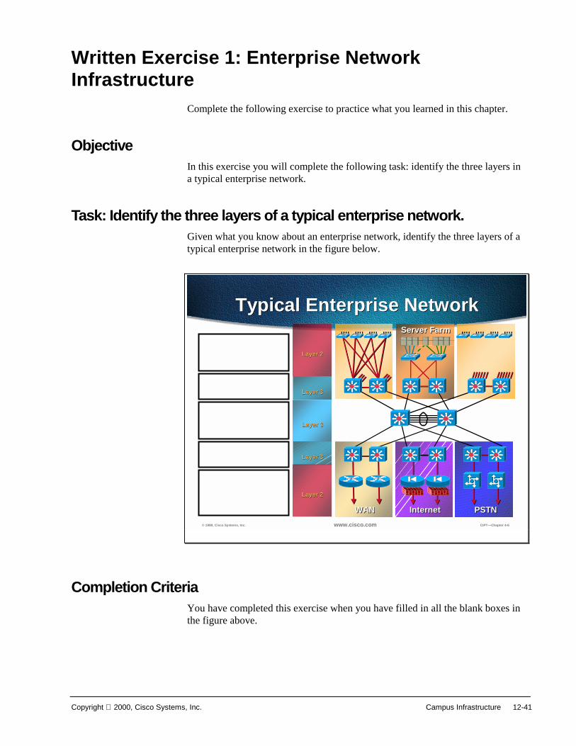
Copyright 2000, Cisco Systems, Inc. Campus Infrastructure 12-41
Written Exercise 1: Enterprise Network Infrastructure
Complete the following exercise to practice what you learned in this chapter.
Objective In this exercise you will complete the following task: identify the three layers in a typical enterprise network.
Task: Identify the three layers of a typical enterprise network. Given what you know about an enterprise network, identify the three layers of a typical enterprise network in the figure below.
© 1999, Cisco Systems, Inc. www.cisco.com CIPT—Chapter 4-6
Layer 3Layer 3
Layer 3Layer 3
Layer 2Layer 2
WANWAN InternetInternet PSTNPSTN
Layer 3Layer 3
Layer 2Layer 2
Server FarmServer Farm
Typical Enterprise NetworkTypical Enterprise Network
Completion Criteria You have completed this exercise when you have filled in all the blank boxes in the figure above.

12-42 Cisco IP Telephony Copyright 2000, Cisco Systems, Inc.
Written Exercise 2: Catalyst Family of Switches Complete the following exercise to practice what you learned in this chapter.
Objective In this exercise you will complete the following tasks: Identify the capabilities of the following catalyst switches:
■ Catalyst 6000
■ Catalyst 5000
■ Catalyst 4000
■ Catalyst 3500
Task: Identify the capabilities of the Catalyst Family of Switches Given what you know about the capabilities of the Catalyst Family of Switches, identify with a “Y” for yes and “N” for No the capabilities of the following switches:
■ Catalyst 6000
■ Catalyst 5000
■ Catalyst 4000
■ Catalyst 3500

Copyright 2000, Cisco Systems, Inc. Campus Infrastructure 12-43
© 1999, Cisco Systems, Inc. www.cisco.com CIPT—Chapter 4-8
Capabilities within the Catalyst Family of Switches
Capabilities within the Catalyst Family of Switches
Catalyst 6000
Catalyst 3500
Catalyst 4000
Catalyst 5000
Congestion Avoidance (WRED)
Policing
Congestion Management (WRR)
Re-Classify ToS
Multiple Queues
Re-Classify CoS
Priority Queue
Ability to Trust
Capabilities
Completion Criteria You have completed this exercise when you have filled in the blank spaces in the table.
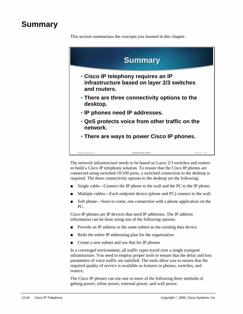
12-44 Cisco IP Telephony Copyright 2000, Cisco Systems, Inc.
Summary This section summarizes the concepts you learned in this chapter.
? 2000, Cisco Systems, Inc. www.cisco.com CIPT v2.0? 3-33
SummarySummary
• Cisco IP telephony requires an IPinfrastructure based on layer 2/3 switchesand routers.
• There are three connectivity options to thedesktop.
• IP phones need IP addresses.• QoS protects voice from other traffic on the
network.• There are ways to power Cisco IP phones.
The network infrastructure needs to be based on Layer 2/3 switches and routers to build a Cisco IP telephony solution. To ensure that the Cisco IP phones are connected using switched 10/100 ports, a switched connection to the desktop is required. The three connectivity options to the desktop are the following:
■ Single cable—Connect the IP phone to the wall and the PC to the IP phone.
■ Multiple cables—Each endpoint device (phone and PC) connect to the wall.
■ Soft phone—Soon to come, one connection with a phone application on the PC.
Cisco IP phones are IP devices that need IP addresses. The IP address information can be done using one of the following options:
■ Provide an IP address in the same subnet as the existing data device
■ Redo the entire IP addressing plan for the organization
■ Create a new subnet and use that for IP phones
In a converged environment, all traffic types travel over a single transport infrastructure. You need to employ proper tools to ensure that the delay and loss parameters of voice traffic are satisfied. The tools allow you to ensure that the required quality of service is available as features in phones, switches, and routers.
The Cisco IP phones can use one or more of the following three methods of getting power; inline power, external power, and wall power.
Copyright 2000, Cisco Systems, Inc. Campus Infrastructure 12-45
Review Questions Answer the following questions.
? 2000, Cisco Systems, Inc. www.cisco.com CIPT v2.0? 3-34
Review QuestionsReview Questions
1. What are the three network layers of atypical enterprise network?
2. What are the IP addressing options toaccommodate Cisco IP phones?
3. Inline power to the phones uses whichpairs?
4. When QoS tools are used, whereshould the trust boundary beestablished?
Q1) The typical enterprise network layer consists of three network layers. What are the three network layers?
Q2) Cisco IP phones need IP addresses. What are the IP addressing options that can be used to accommodate the Cisco IP phones?
Q3) Inline power is an option to power the Cisco IP phones. Which pairs are used to provide inline power to the Cisco IP phones?

12-46 Cisco IP Telephony Copyright 2000, Cisco Systems, Inc.
Q4) QoS tools are used to protect voice traffic from all other types of traffic. Where should the trust boundary be established?
Laboratory Exercise

13
Distributed CallProcessing
OverviewIn this deployment scenario, Cisco CallManagers, voice messaging, and digitalsignal processor (DSP) resources are located at each site. This deploymentmodel can initially support up to 10 sites networked across the IP WAN. Voicecalls between sites use the IP WAN as the primary path and the PSTN as thesecondary path in the event the IP WAN is down or has insufficient resources tohandle additional calls. Whether calls use the IP WAN or use the PSTN istransparent to both the calling party and the called party. This chapteremphasizes issues specific to the distributed call processing model, withreference to relevant material in other sections of this guide.
The following topics are in this chapter:
■ Objectives
■ Call Admission Control
■ Dial Plan Considerations
■ CallManager Cluster Considerations
■ DSP Resource Provisioning for Transcoding and Conferencing
■ Summary
■ Review Questions

13-2 Cisco IP Telephony Copyright 2000, Cisco Systems, Inc.
ObjectivesThis section lists the chapter objectives.
© 2000, Cisco Systems, Inc. www.cisco.com CIPT v2.0—14-3
ObjectivesObjectives
Upon completion of this chapter, you will beable to perform the following tasks:• Identify design characteristics in building a
CIPT WAN deployment using Distributed CallProcessing
• Configure the IOS gatekeeper and dial plans touse the IP WAN link without oversubscribing
• Configure the each site to have a redundantpath using an ISDN or PSTN path.
Upon completion of this chapter, you will be able to perform the following tasks:
■ Given a list of Cisco IP telephony characteristics identify the designcharacteristics for building a CIPT WAN deployment using distributed callprocessing.
■ Given two isolated campus CIPT solutions, configure a IOS gatekeeper anddial plans to use the IP WAN link without oversubscribing the link.
■ Given a CIPT WAN deployment solution, configure each site to have aredundant path using an ISDN or PSTN path.

Copyright 2000, Cisco Systems, Inc. Distributed Call Processing 13-3
Visual Objective
© 2000, Cisco Systems, Inc. www.cisco.com CIPT v2.0—13-4
PSTNV
Site ASite B
Site C
V
V
Visual Objective
A
A
A
IP WAN(Primary Voice Path)
Gatekeeper
uOne
uOne
uOne
Student Pods will be interconnected through a Gatekeeper and have back up path to the PSTNStudent Pods will be interconnected through a Gatekeeper and have back up path to the PSTN
DSP
DSPDSP
Using the isolated campus deployments, you will interconnect and configuregateways, gatekeeper, and dial plan architecture to place phone calls over the IPWAN. Configure a back-up path to the PSTN if the IP WAN is congested oroversubscribed.
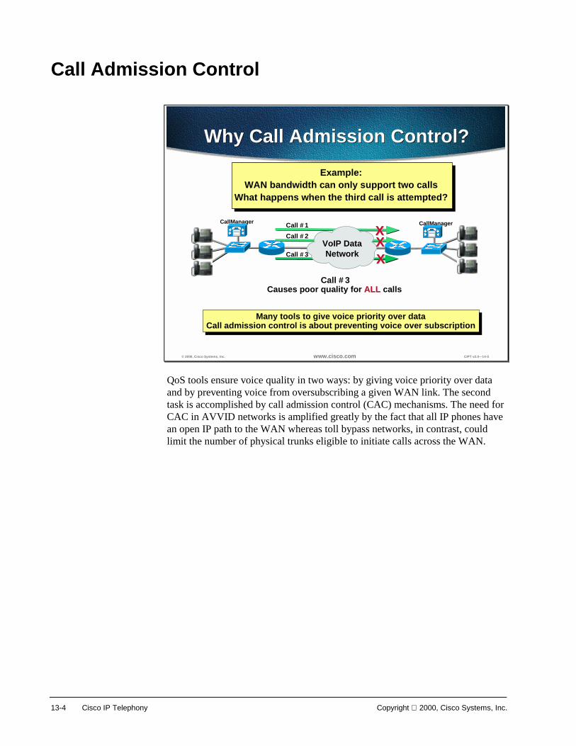
13-4 Cisco IP Telephony Copyright 2000, Cisco Systems, Inc.
Call Admission Control
© 2000, Cisco Systems, Inc. www.cisco.com CIPT v2.0—14-5
CallManager
Example:WAN bandwidth can only support two calls
What happens when the third call is attempted?
Call #1Call #2
Call #3Causes poor quality for ALLALL calls
Call #3
Why Call Admission Control?Why Call Admission Control?
VoIP DataNetwork
Many tools to give voice priority over dataCall admission control is about preventing voice over subscription
Many tools to give voice priority over dataCall admission control is about preventing voice over subscription
CallManager
XXXXXX
QoS tools ensure voice quality in two ways: by giving voice priority over dataand by preventing voice from oversubscribing a given WAN link. The secondtask is accomplished by call admission control (CAC) mechanisms. The need forCAC in AVVID networks is amplified greatly by the fact that all IP phones havean open IP path to the WAN whereas toll bypass networks, in contrast, couldlimit the number of physical trunks eligible to initiate calls across the WAN.

Copyright 2000, Cisco Systems, Inc. Distributed Call Processing 13-5
© 2000, Cisco Systems, Inc. www.cisco.com CIPT v2.0—14-6
PSTNRouter/GW
CallManager
VDSP
IPWAN
IP Phones
User dials555-1212
CCM strips 1st 3 digits for
IP WAN
XX
“1212” sent to remote siteProper QoS Ensured
User dials555-1212
“1408-555-1212” sent to PSTN
IP WAN goes down or not enough resources
CCM inserts “1408”for PSTN
“Dynamic Alternate Routing”
Cisco CallManagerqueries GK
for Call AdmissionMay I place
a call?
Yes
Gatekeeper Based AdmissionControl
Gatekeeper Based AdmissionControl
IOS GK
For deployments of the distributed call processing model, use the H.323gatekeeper controlled method to provide CAC. In this design, the CallManagerregisters with the Cisco IOS gatekeeper, also known as Multimedia ConferenceManager (MCM), as a VoIP gateway and queries it each time it wants to makean IP WAN call. The Cisco IOS gatekeeper associates each CallManager with azone that has specific bandwidth limitations. Thus the maximum amount ofbandwidth consumed by IP WAN voice calls in or out of a zone can be limitedby the Cisco IOS gatekeeper.
In brief, when the CallManager wants to place an IP WAN call it first requestspermission of the gatekeeper. If the gatekeeper grants the call it is placed acrossthe IP WAN. If the gatekeeper denies the request the CallManager places the callacross the secondary path, the PSTN.
This is effectively a call accounting method of providing admission control inwhich the gatekeeper simply keeps track of the bandwidth the IP WAN callsconsume. The maximum bandwidth setting for a zone should take into accountthe limitation that the WAN link not be filled with more than 75% voice.
Note In this scheme, IP phones are not mobile between sites. Should an IP phoneregister across the WAN, admission control would not operate as designed.
In this model it is important that the dial plan be tightly coupled with thegatekeeper CAC mechanism because it is the dial plan that ultimately decideswhen to place a call across the IP WAN and what to do if the gatekeeper rejectsit.
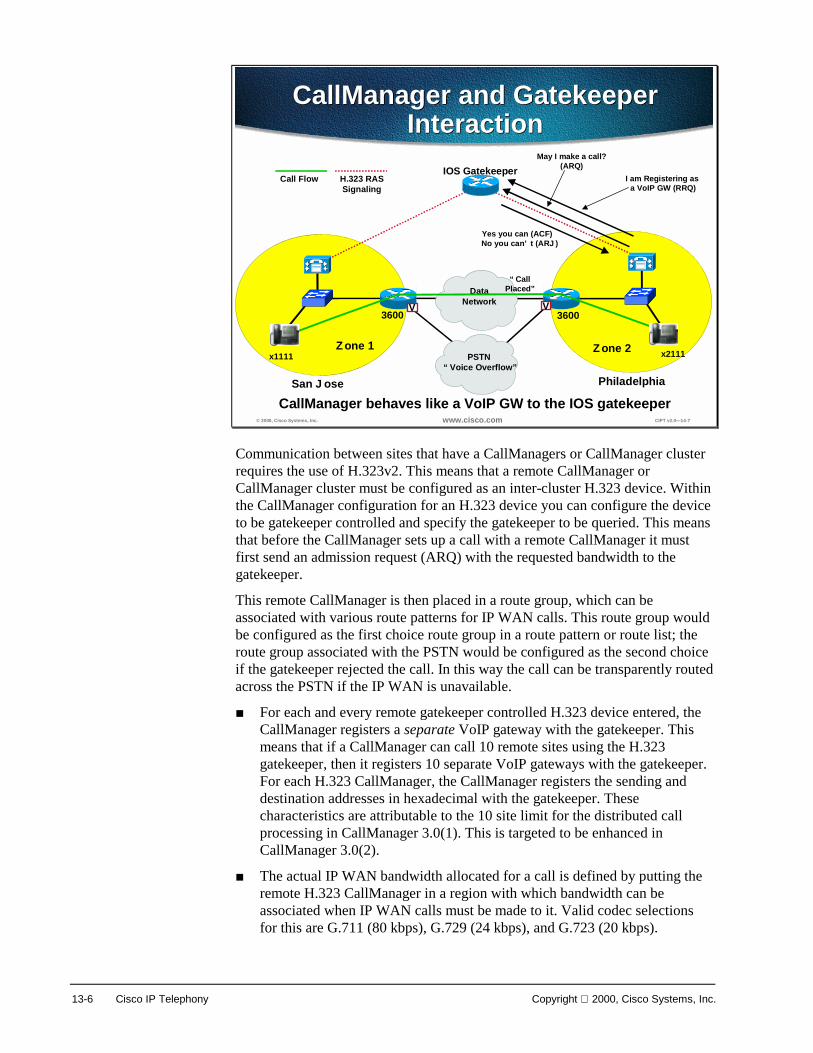
13-6 Cisco IP Telephony Copyright 2000, Cisco Systems, Inc.
© 2000, Cisco Systems, Inc. www.cisco.com CIPT v2.0—14-7
36003600
DataNetwork
x1111 x2111Zone 1 Zone 2
CallManager and GatekeeperInteraction
CallManager and GatekeeperInteraction
PSTN“Voice Overflow”
Call FlowIOS Gatekeeper
May I make a call?(ARQ)
Yes you can (ACF)No you can’t (ARJ)
VV
H.323 RASSignaling
I am Registering as a VoIP GW (RRQ)
San Jose Philadelphia
CallManager behaves like a VoIP GW to the IOS gatekeeper
“Call Placed”
Communication between sites that have a CallManagers or CallManager clusterrequires the use of H.323v2. This means that a remote CallManager orCallManager cluster must be configured as an inter-cluster H.323 device. Withinthe CallManager configuration for an H.323 device you can configure the deviceto be gatekeeper controlled and specify the gatekeeper to be queried. This meansthat before the CallManager sets up a call with a remote CallManager it mustfirst send an admission request (ARQ) with the requested bandwidth to thegatekeeper.
This remote CallManager is then placed in a route group, which can beassociated with various route patterns for IP WAN calls. This route group wouldbe configured as the first choice route group in a route pattern or route list; theroute group associated with the PSTN would be configured as the second choiceif the gatekeeper rejected the call. In this way the call can be transparently routedacross the PSTN if the IP WAN is unavailable.
■ For each and every remote gatekeeper controlled H.323 device entered, theCallManager registers a separate VoIP gateway with the gatekeeper. Thismeans that if a CallManager can call 10 remote sites using the H.323gatekeeper, then it registers 10 separate VoIP gateways with the gatekeeper.For each H.323 CallManager, the CallManager registers the sending anddestination addresses in hexadecimal with the gatekeeper. Thesecharacteristics are attributable to the 10 site limit for the distributed callprocessing in CallManager 3.0(1). This is targeted to be enhanced inCallManager 3.0(2).
■ The actual IP WAN bandwidth allocated for a call is defined by putting theremote H.323 CallManager in a region with which bandwidth can beassociated when IP WAN calls must be made to it. Valid codec selectionsfor this are G.711 (80 kbps), G.729 (24 kbps), and G.723 (20 kbps).

Copyright 2000, Cisco Systems, Inc. Distributed Call Processing 13-7
Note With CallManager Release 3.0(1) 128 kbps is always requested in the ARQ,regardless of the IP WAN codec to be used. This requires the use of a single WAN codecfor all IP WAN calls, as well as using a fudge factor to determine the maximum amount ofbandwidth entered in the IOS gatekeeper. In effect, every 128 kbps entered in thegatekeeper equates to one call at 80 kbps or 24 kbps, depending on the WAN codecselection. This is further explained later in this section.

13-8 Cisco IP Telephony Copyright 2000, Cisco Systems, Inc.
© 2000, Cisco Systems, Inc. www.cisco.com CIPT v2.0—14-8
3600
Zone 2PSTN
IOS Gatekeeper
V
IP WAN
RCFCallManager
PhiladelphiaPhiladelphia
RRQ
CallManager RegistrationCharacteristics
CallManager RegistrationCharacteristics
The IOS Gatekeeper (GK) uses a zone subnet filter to place CallManager with aZone. Each remote Cisco CallManager must configure across the IP WAN as a“GK Controlled” H.323 Inter-cluster trunk. Every GK Controlled remote CiscoCallManager as a separate VoIP Gateway (GW) with the gatekeeper. Forexample; for 9 remotes, a Cisco CallManager will register as 9 VoIP GWs. TheCisco CallManager registers IP SA/DA (in hexadecimal) of remote CiscoCallManager as fully qualified name, however the Cisco CallManager cannot yetregister E.164 address or E.164 address range.
The Cisco CallManager sends Full Registration Repeat Request (RRQ) everyminute (default). This timer is configurable and Cisco CallManager does not useH.323v2 lightweight registration. The Gatekeeper will then respond with aRegistration Confirmation (RCF).
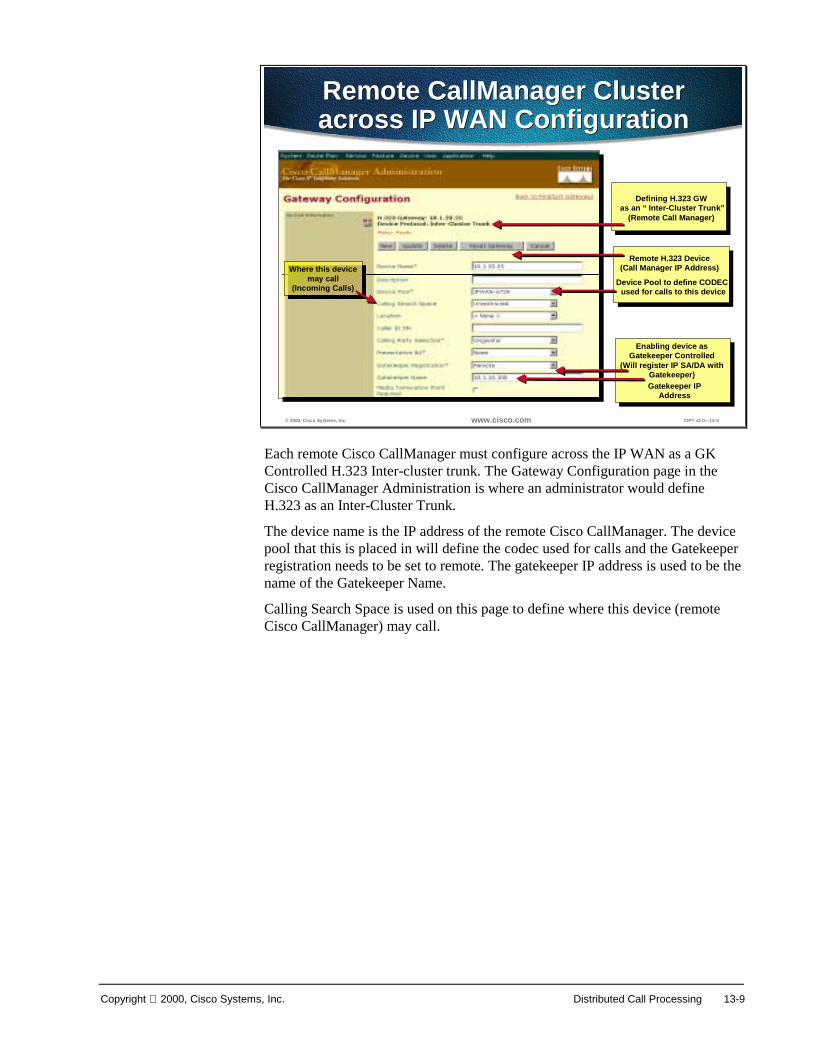
Copyright 2000, Cisco Systems, Inc. Distributed Call Processing 13-9
© 2000, Cisco Systems, Inc. www.cisco.com CIPT v2.0—14-9
Remote CallManager Clusteracross IP WAN ConfigurationRemote CallManager Clusteracross IP WAN Configuration
Enabling device asGatekeeper Controlled
(Will register IP SA/DA withGatekeeper)Gatekeeper IP
Address
Remote H.323 Device(Call Manager IP Address)
Defining H.323 GWas an “Inter-Cluster Trunk”
(Remote Call Manager)
Device Pool to define CODEC used for calls to this device
Where this devicemay call
(Incoming Calls)
Where this devicemay call
(Incoming Calls)
Each remote Cisco CallManager must configure across the IP WAN as a GKControlled H.323 Inter-cluster trunk. The Gateway Configuration page in theCisco CallManager Administration is where an administrator would defineH.323 as an Inter-Cluster Trunk.
The device name is the IP address of the remote Cisco CallManager. The devicepool that this is placed in will define the codec used for calls and the Gatekeeperregistration needs to be set to remote. The gatekeeper IP address is used to be thename of the Gatekeeper Name.
Calling Search Space is used on this page to define where this device (remoteCisco CallManager) may call.

13-10 Cisco IP Telephony Copyright 2000, Cisco Systems, Inc.
© 2000, Cisco Systems, Inc. www.cisco.com CIPT v2.0—14-10
3600
Zone 2PSTN
IOS Gatekeeper
V
IP WAN
ACF/ARJ CallManager
Philadelphia
ARQ
CallManager ARQCharacteristics
CallManager ARQCharacteristics
Cisco CallManager does not use E.164 in Automatic Repeat Request (ARQ) andthe ARQ the Cisco CallManager uses SA/DA in hexadecimal of the target H.225device. Cisco CallManager cannot use returned IP address in the advancedcommunications function to be used for H.225 target address. This means aH.323 device for every remote Cisco CallManager.
The bandwidth always issued in the ARQ regardless of codec type is 128kbps.This requires use of single WAN CODEC with a fudge factor for maximumbandwidth entered in IOS gatekeeper:
■ G.711 (80kbps) = 128kbps in GK
■ G.729 (24kbps) = 128kbps in GK

Copyright 2000, Cisco Systems, Inc. Distributed Call Processing 13-11
© 2000, Cisco Systems, Inc. www.cisco.com CIPT v2.0—14-11
3600
Zone 1 PSTN
IOS Gatekeeper
V
IP WANCallManager
ARQ
ACF
IncomingH.225 Setup
San Jose
Incoming Call from IP WANCharacteristics
Incoming Call from IP WANCharacteristics
1
3
2
When an IP WAN is incoming the terminating Cisco CallManager identifiesincoming CallManager SA/DA combination in H.225 setup by using SA/DA inARQ.In the ARQ,128kbps are used and upon ACF the call is allowed toproceed.
© 2000, Cisco Systems, Inc. www.cisco.com CIPT v2.0—14-12
IP WAN
1.1.1.1 2.2.2.2
Gatekeeper Controlled DevicePointing to 2.2.2.2
Gatekeeper Controlled DevicePointing to 1.1.1.1
Register SA/DA2.2.2.2->1.1.1.1
IOS GatekeeperRegister SA/DA1.1.1.1-2.2.2.2
IP WAN
1.1.1.1 2.2.2.2
ARQ SA/DA1.1.1.1->2.2.2.2
128kbps
IOS Gatekeeper
Registration ProcessARQ Process
Detail of Successful Call FlowCall from 1111 to 2222
Detail of Successful Call FlowCall from 1111 to 2222
ARQ SA/DA1.1.1.1->2.2.2.2
128kbps
H.225 Setup
1111 2222
RTP Stream(Dials 2222)
ACF ACF
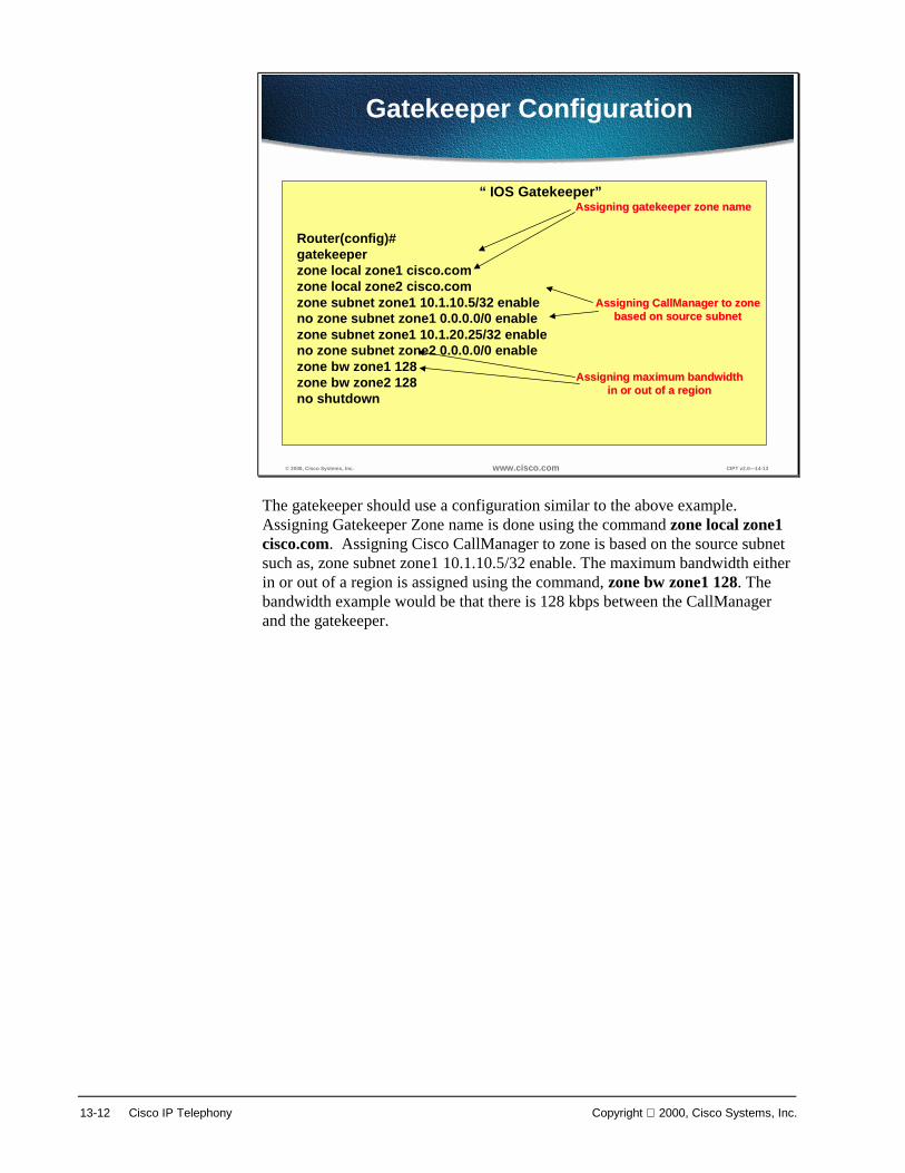
13-12 Cisco IP Telephony Copyright 2000, Cisco Systems, Inc.
© 2000, Cisco Systems, Inc. www.cisco.com CIPT v2.0—14-13
Gatekeeper Configuration
Router(config)#gatekeeperzone local zone1 cisco.comzone local zone2 cisco.comzone subnet zone1 10.1.10.5/32 enableno zone subnet zone1 0.0.0.0/0 enablezone subnet zone1 10.1.20.25/32 enableno zone subnet zone2 0.0.0.0/0 enablezone bw zone1 128zone bw zone2 128no shutdown
“IOS Gatekeeper”Assigning gatekeeper zone nameAssigning gatekeeper zone name
Assigning maximum bandwidthAssigning maximum bandwidthin or out of a regionin or out of a region
Assigning CallManager to zoneAssigning CallManager to zonebased on source subnetbased on source subnet
The gatekeeper should use a configuration similar to the above example.Assigning Gatekeeper Zone name is done using the command zone local zone1cisco.com. Assigning Cisco CallManager to zone is based on the source subnetsuch as, zone subnet zone1 10.1.10.5/32 enable. The maximum bandwidth eitherin or out of a region is assigned using the command, zone bw zone1 128. Thebandwidth example would be that there is 128 kbps between the CallManagerand the gatekeeper.
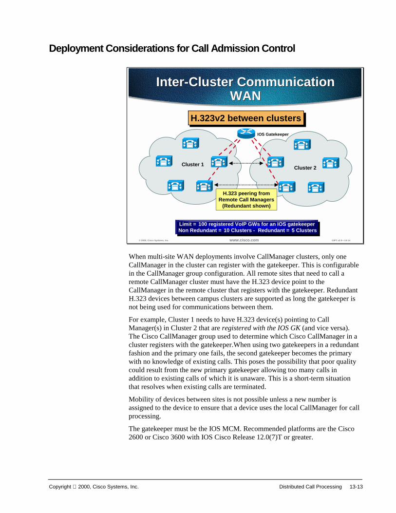
Copyright 2000, Cisco Systems, Inc. Distributed Call Processing 13-13
Deployment Considerations for Call Admission Control
© 2000, Cisco Systems, Inc. www.cisco.com CIPT v2.0—14-14
Inter-Cluster CommunicationWAN
Inter-Cluster CommunicationWAN
Cluster 2Cluster 1
Limit = 100 registered VoIP GWs for an IOS gatekeeperNon Redundant = 10 Clusters - Redundant = 5 ClustersLimit = 100 registered VoIP GWs for an IOS gatekeeperNon Redundant = 10 Clusters - Redundant = 5 Clusters
IOS Gatekeeper
H.323 peering fromRemote Call Managers
(Redundant shown)
H.323v2 between clustersH.323v2 between clusters
When multi-site WAN deployments involve CallManager clusters, only oneCallManager in the cluster can register with the gatekeeper. This is configurablein the CallManager group configuration. All remote sites that need to call aremote CallManager cluster must have the H.323 device point to theCallManager in the remote cluster that registers with the gatekeeper. RedundantH.323 devices between campus clusters are supported as long the gatekeeper isnot being used for communications between them.
For example, Cluster 1 needs to have H.323 device(s) pointing to CallManager(s) in Cluster 2 that are registered with the IOS GK (and vice versa).The Cisco CallManager group used to determine which Cisco CallManager in acluster registers with the gatekeeper.When using two gatekeepers in a redundantfashion and the primary one fails, the second gatekeeper becomes the primarywith no knowledge of existing calls. This poses the possibility that poor qualitycould result from the new primary gatekeeper allowing too many calls inaddition to existing calls of which it is unaware. This is a short-term situationthat resolves when existing calls are terminated.
Mobility of devices between sites is not possible unless a new number isassigned to the device to ensure that a device uses the local CallManager for callprocessing.
The gatekeeper must be the IOS MCM. Recommended platforms are the Cisco2600 or Cisco 3600 with IOS Cisco Release 12.0(7)T or greater.

13-14 Cisco IP Telephony Copyright 2000, Cisco Systems, Inc.
© 2000, Cisco Systems, Inc. www.cisco.com CIPT v2.0—14-15
Multi-site WAN Topologies
Hub and SpokeTopologies Admission Control + Capacity Planning
Ensure voice traffic at every site does notexceed configured WAN bandwidth
Minimum requirements for voice, videoand data should not exceed 75% of link or
VC bandwidth
(Remaining 25% for routing protocol updatesand link layer header BW consumption and so forth)
Admission Control + Capacity Planning
Ensure voice traffic at every site does notexceed configured WAN bandwidth
Minimum requirements for voice, videoand data should not exceed 75% of link or
VC bandwidth
(Remaining 25% for routing protocol updatesand link layer header BW consumption and so forth)
Required Link Capacity =
(Min BW for Voice + Min BW for Video + Min BW for Data) / 0.75
Required Link Capacity =
(Min BW for Voice + Min BW for Video + Min BW for Data) / 0.75
A maximum of 10 sites can be networked across the IP WAN in multi-site WANdeployments with distributed call processing. Only hub and spoke topologies aresupported. Only one active IOS gatekeeper can be used with CallManager 3.0(1)with no more than 10 CallManagers registered with the gatekeeper. An HSRPbackup gatekeeper can be used. CallManager 3.0(2) is targeted at using multiplegatekeepers in a hierarchical approach.
© 2000, Cisco Systems, Inc. www.cisco.com CIPT v2.0—14-16
IP WAN
CM-1
Networking Across IP WANNetworking Across IP WANIOS Gatekeeper
H.323 device +route pattern forremote locations
Add 11th Site1. For 11th site must add H.323 device + route pattern for every other site2. For other 10 sites must add H.323 device and route pattern for 11th site
Add 11th SiteAdd 11th Site1. For 11th site must add H.323 device + route pattern for every other site2. For other 10 sites must add H.323 device and route pattern for 11th site
CM-2
CM-3
CM-4
CM-5CM-6
CM-7
CM-8
CM-9
CM-10
CM-11
Add 11th Site/CM
10 SitesTotal of 90 H.323 devices
and route patterns
10 SitesTotal of 90 H.323 devices
and route patterns
Requires full meshof H.323 devices
and route patterns
Requires full meshof H.323 devices
and route patterns

Copyright 2000, Cisco Systems, Inc. Distributed Call Processing 13-15
Dial Plan Considerations
© 2000, Cisco Systems, Inc. www.cisco.com CIPT v2.0—14-17
PSTN
IP WAN
A
A
V
V
Gatekeeper(s)
Primary Voice PathPrimary Voice PathStrip “52” and deliver
61111 to remote CallManager
Secondary Voice PathSecondary Voice PathPre-pend “1408” and send to PSTN
(408) 526-XXXX5 Digit Internal Dialing
Users required to dial7 digits for Intersite calls
“526-XXXX”
Dial Plan ConfigurationDial Plan Configuration
In the example depicted in the figure above, users dial five digits for internalcalls and seven digits for inter-site calls across the IP WAN. If the IP WAN isdown or has insufficient resources, the PSTN is used transparently for inter-sitecalls. For long distance calls that will be directed to the PSTN, users dial theaccess code 9 followed by 1 + area code and 7-digit number. Users dialing localPSTN calls dial 9 plus the 7-digit number. This model also provides gatewayredundancy in the event of a gateway or trunk failure to the PSTN. The PSTNgateways are IOS gateways using H.323.
The goal of this dial plan is to be able to dial the San Jose location using onlyseven digits where calls take the IP WAN as the first choice and the PSTN as thesecond choice. Thus, users in Philadelphia should be able to dial San Jose usersat (408) 526-XXXX by simply dialing 526XXXX.
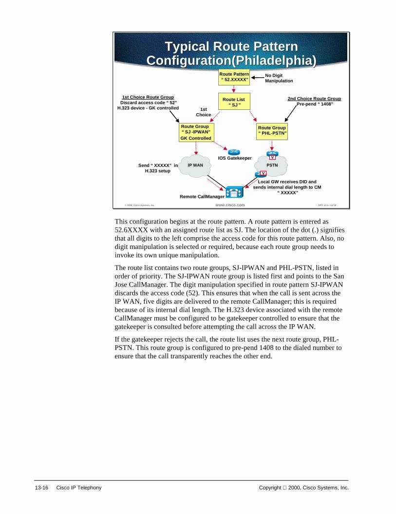
13-16 Cisco IP Telephony Copyright 2000, Cisco Systems, Inc.
© 2000, Cisco Systems, Inc. www.cisco.com CIPT v2.0—14-18
Route Pattern“52.XXXXX”
Route List“SJ”
Route Group“SJ-IPWAN”
1stChoice
PSTNIP WAN
Route Group“PHL-PSTN”
No Digit Manipulation
VIOS Gatekeeper
GK Controlled
Send “XXXXX” in H.323 setup V
Local GW receives DID andsends internal dial length to CM
“XXXXX”Remote CallManager
1st Choice Route GroupDiscard access code “52”
H.323 device - GK controlled
2nd Choice Route GroupPre-pend “1408”
Typical Route PatternConfiguration(Philadelphia)
Typical Route PatternConfiguration(Philadelphia)
This configuration begins at the route pattern. A route pattern is entered as52.6XXXX with an assigned route list as SJ. The location of the dot (.) signifiesthat all digits to the left comprise the access code for this route pattern. Also, nodigit manipulation is selected or required, because each route group needs toinvoke its own unique manipulation.
The route list contains two route groups, SJ-IPWAN and PHL-PSTN, listed inorder of priority. The SJ-IPWAN route group is listed first and points to the SanJose CallManager. The digit manipulation specified in route pattern SJ-IPWANdiscards the access code (52). This ensures that when the call is sent across theIP WAN, five digits are delivered to the remote CallManager; this is requiredbecause of its internal dial length. The H.323 device associated with the remoteCallManager must be configured to be gatekeeper controlled to ensure that thegatekeeper is consulted before attempting the call across the IP WAN.
If the gatekeeper rejects the call, the route list uses the next route group, PHL-PSTN. This route group is configured to pre-pend 1408 to the dialed number toensure that the call transparently reaches the other end.

Copyright 2000, Cisco Systems, Inc. Distributed Call Processing 13-17
Bandwidth Consumption of Dialed Number
© 2000, Cisco Systems, Inc. www.cisco.com CIPT v 2.0—12-33
Recommended BandwidthConfiguration
Recommended BandwidthConfiguration
Number ofInter-ClusterCalls
BandwidthRequired per Call
Bandwidth Requiredon WAN Links(LLQ/CBWFQ1)
BandwidthConfigured onGatekeeper
WithoutcRTP2
WithoutcRTP
WithoutcRTP
WithcRTP
WithcRTP
WithcRTP
25
10
24 Kbps24 Kbps
24 Kbps12 Kbps12 Kbps
12 Kbps 240 Kbps120 Kbps48 Kbps
120 Kbps60 Kbps24 Kbps
1.280 Mbps640 Kbps256 Kbps
1.280 Mbps640 Kbps256 Kbps
Inter-Cluster CallsUsing G.729
Inter-Cluster CallsUsing G.729
1. Low latency queuing/class based weighted fair queuing2. Compressed Real-time Transport Protocol
1. Low latency queuing/class based weighted fair queuing2. Compressed Real-time Transport Protocol
© 2000, Cisco Systems, Inc. www.cisco.com CIPT v 2.0—12-34
Recommended BandwidthConfiguration
Recommended BandwidthConfiguration
Number ofInter-ClusterCalls
BandwidthRequired per Call
Bandwidth Requiredon WAN Links(LLQ/CBWFQ)
BandwidthConfigured onGatekeeper
2510
80 Kbps80 Kbps80 Kbps 800 Kbps
400 Kbps160 Kbps
1.280 Mbps640 Kbps256 Kbps
Inter-Cluster CallsUsing G.711
Inter-Cluster CallsUsing G.711
The tables above provide recommendations for bandwidth configuration forinter-cluster calls. Use these tables to ensure enough bandwidth between clustersto ensure quality voice.

13-18 Cisco IP Telephony Copyright 2000, Cisco Systems, Inc.
© 2000, Cisco Systems, Inc. www.cisco.com CIPT v2.0—14-19
Region Codec Matrix Codec “PHL” to “PHL” G.711“PHL to “IPWAN-G729” G.729
Region Codec Matrix Codec “PHL” to “PHL” G.711“PHL to “IPWAN-G729” G.729
PSTN
A
A
V
V
Gatekeeper(s)
San JosePhiladelphia
IP WAN
Devices RegionIP Phones at PHL “PHL”SJ CallManager “IPWAN-G729”
Devices RegionIP Phones at PHL “PHL”SJ CallManager “IPWAN-G729”
Codec Selection Based onRegions
Calls within PHL = G.711Calls from PHL to SJ = G.729
Calls within PHL = G.711Calls from PHL to SJ = G.729
Bandwidth consumed by calls between devices, such as IP phones and gateways,can be controlled by dictating codec usage when setting up regions. Devices areplaced in regions that have a codec specified for all intra-region calls; aparticular code can likewise be specified for inter-region calls. Regions areassigned to devices using a device pool. The supported codecs defined in regionsare G.711, G.729, and G.723 (G.723 is only supported on the Model 12 SP+ andthe Model 30 VIP IP phones). The figure above illustrates the use of regions fordistributed call processing environments where often only two regions need beassigned.
Just one WAN region is associated with all H.323 devices across the IP WANbecause of the single codec restriction. In the future, multiple WAN regions willbe supported.

Copyright 2000, Cisco Systems, Inc. Distributed Call Processing 13-19
CallManager Cluster Considerations
© 2000, Cisco Systems, Inc. www.cisco.com CIPT v2.0—14-20
PSTNV
Site A Site B
Site C
V
V
Cluster ConsiderationsCluster Considerations
10,000 IP phones per cluster.2,500 IP phones per CallManager even under failure conditions.One single CallManager can register with IOS gatekeeper.Max 10 clusters (5 redundant)—IOS GK for CAC.
10,000 IP phones per cluster.2,500 IP phones per CallManager even under failure conditions.One single CallManager can register with IOS gatekeeper.Max 10 clusters (5 redundant)—IOS GK for CAC.
A
A
A
IP WAN(Primary Voice Path)
Gatekeeper
DSP
DSPDSP
uOneuOne
uOne
The following design considerations apply for CallManager clusters in adistributed call-processing environment using CallManager 3.0(1):
■ Each CallManager cluster can support 10,000 users.
■ No more than 2500 users can be registered on any given CallManager, evenunder failure conditions.
■ Only a single CallManager within a cluster can register with the IOSgatekeeper.
■ We recommend that only a single CallManager within a cluster be allowedto register with the gatekeeper. If a second is configured for redundancy,then only five sites can be deployed in this manner.
The major design consideration regarding CallManager clusters in this type ofdeployment is how the H.323 peering is achieved between clusters. Based on theway that CallManager 3.0(1) registers with the gatekeeper, we recommend thatno redundant peering occur between clusters. This is targeted to change in theCallManager 3.0(2) time frame.

13-20 Cisco IP Telephony Copyright 2000, Cisco Systems, Inc.
DSP Resource Provisioning for Transcoding andConferencing
© 2000, Cisco Systems, Inc. www.cisco.com CIPT v2.0—14-21
Router/GW
Router/GW
CallManagerA
IP WAN
uOneGateserverG.711 Only
Transcoding
Intra Region
A = G.711
Inter RegionA to B
G.729a
CallManager B
uOneGateserverG.711 Only
DSP
Region ARegion A Region BRegion BIntra Region
B = G.711
Inter RegionB to A
G.729a
1. User dials 555-1212 in Region B dials Region A Voice Mail2. CallManager B sees that destination is Region A and Low Bit Rate Codec3. CallManager A sees a Low Bit Rate incoming Call for a “G.711 only” device4. Media Stream directed to “terminating” side DSP farm
= DSP Farm
G.711 Call LegCompressed Call Leg
DSP
555-1212
Call setup to CallManager A for 555-1212
Setup RTP Stream to CallManagers DSP Farm
User Dials555-1212
User Dials555-1212
DSP Resources for TranscodingOnly used when needed
DSP
This section briefly considers DSP resources in distributed call processingenvironments. In multi-site WAN deployment with distributed call processing,each site is required to havDSP resources for conferencing and for transcodingacross the IP WAN. Conferencing and transcoding services are enabled by theMedia Termination Point (MTP) application.
The main purpose of transcoding DSP resources is to perform conversionbetween different codec types in an RTP stream in the event of a codecmismatch. For example, a compressed G.729 media RTP stream across the IPWAN might need to terminate on a device that only supported G.711. Thetranscoding DSP resource would terminate the G.729 media stream and convertit to G.711. This allows the media stream to remain compressed across theWAN. The figure above depicts the function of DSP resources across the IPWAN in the following steps:
Step 1 Caller 555-1212 in region B dials region A voice mail.
Step 2 CallManager B sees that the destination is region A, LBR codec.
Step 3 CallManager A sees an LBR incoming call for a G.711-only device.
Step 4 The media stream is directed to the terminating side DSP farm.
The number of resources allocated is based upon the requirements fortranscoding to voice mail as well as transcoding to G.711 for other applicationssuch as conferencing. These numbers are calculated based upon the ratio of usersto voice mail ports and the volume of conference calls placed.

Copyright 2000, Cisco Systems, Inc. Distributed Call Processing 13-21
SummaryThis section summarizes the concepts you learned in this chapter.
© 2000, Cisco Systems, Inc. www.cisco.com CIPT v2.0—14-23
SummarySummary
• QoS tools ensure voice quality in two ways.• Maximum bandwidth WAN link may not be
filled with more than 75 percent voice.• Remote Cisco CallManagers must
configure across the IP WAN as “GKControlled” H.323 inter-cluster trunks.
Interconnecting two or more isolated Campus LAN CIPT deployments shouldconsider the following:
■ QoS tools ensure voice quality in two ways: by giving voice priority overdata and by preventing voice from oversubscribing a given WAN link.
■ The maximum bandwidth setting for a zone should take into account thelimitation that the WAN link may not be filled with more than 75 percentvoice.
■ Each remote Cisco CallManager must configure across the IP WAN as a“GK Controlled” H.323 inter-cluster trunk.

13-22 Cisco IP Telephony Copyright 2000, Cisco Systems, Inc.
Review QuestionsAnswer the following questions.
© 2000, Cisco Systems, Inc. www.cisco.com CIPT v2.0—14-24
Review QuestionsReview Questions
1. Can devices at a LAN site be moved to anotherLAN site that is interconnected acrossthe WAN?
2. What us the recommended number ifCallManager in one cluster used to register as aH.323v2 device with the IOS Gatekeeper?
3. A call uses G.729 across the IP WAN and needsto speak with a device that uses G.711 only.What resource us needed to make this happen?
Q1) In a WAN CIPT deployment that uses distributed call processing, are the devicesat one LAN site able to be moved to another LAN site that is across the WAN?
Q2) Between sites an IOS Gatekeeper is used to control the bandwidth across theWAN. What is the recommended number of CallManagers in the same clusterthat is used to register with the IOS Gatekeeper as an H.323v2 device?
Q3) To conserve bandwidth across the WAN, compressed CODEC (G.723 andG.729) are used. If a call that goes across the WAN uses G.729 and the devicethat it needs to speak with only uses G.711, what resource is needed to make thisconversation happen?

14
Centralized CallProcessing
OverviewIn a multi-site WAN deployment that uses centralized call processing the CiscoCallManagers are centrally located at the hub or aggregation site with no localcall processing at the branch location.
This chapter emphasizes issues specific to the centralized call processing modelin the following topics:
■ Objectives
■ Call Admission Control
■ Dial Plan Considerations
■ CallManager Cluster Considerations
■ DSP Resource Provisioning for Transcoding and Conferencing
■ Summary
■ Review Questions

14-2 Cisco IP Telephony Copyright 2000, Cisco Systems, Inc.
ObjectivesThis section lists the chapter objectives.
© 2000, Cisco Systems, Inc. www.cisco.com CIPT V2.0—15-3
ObjectivesObjectives
Upon completion of this chapter, you will beable to perform the following tasks:• Identify design characteristics when building a
remote branch that uses centralized callprocessing.
• Configure the remote branch office to get thecall processing from the centralized site.
• Configure the remote branch office to have aredundant path using an ISDN or PSTN path.
Upon completion of this chapter, you will be able to perform the following tasks:
■ Given a list of design characteristics, identify the design considerationswhen building a remote branch office that uses centralized call processing.
■ Given a CIPT isolated deployment, extend the call processing services to theremote branch office.
■ Given a CIPT isolated deployment with remote branch offices usingcentralized call processing, configure a redundant path for the IP WAN thatuses ISDN or the PSTN.

Copyright 2000, Cisco Systems, Inc. Centralized Call Processing 14-3
Visual Objective
© 2000, Cisco Systems, Inc. www.cisco.com CIPT V2.0—15-4
IP WAN
PSTN
V
V
IP WANRouter/GW
V
IP WANRouter/GW
V
Site ALocation A = 512kbps Max
Site BLocation B = 128kbps Max
Site CLocation C = 256kbps Max
TelecommuterLocation D = 56kbps Max
CentralizedCallManager Cluster
DSP
IP WANRouter/GW
Multi-site WAN Deployments“Centralized Call Processing”
The central site will include a Cisco CallManager, voice msg + DSP resource atand the remote site can support up to 2500 users total. There will be one activeCisco CallManager that the IP phones will register to. Call admission controlimposes a limit on the number of calls per site (location). Unless there is a dialbackup configured in the dial plan, if the IP WAN link goes down there is noservice. Now that the Cisco IOS gateways support H.323 v2 the remote branchoffices do not need to use software MTP to gain access to supplementaryservices.
G.711 or G.729 per call (Cat 6K/4k DSP Farm required for G.729) and usepartitions to allow sites to use same PSTN access code.

14-4 Cisco IP Telephony Copyright 2000, Cisco Systems, Inc.
Centralized Call Processing Considerations
© 2000, Cisco Systems, Inc. www.cisco.com CIPT V2.0—15-5
Centralized Call ProcessingConsiderations
Centralized Call ProcessingConsiderations
• Call AdmissionControl
• Dial Plan• QoS• DSP
ProvisioningPC Stations
CatalystSwitch
CallManager
uOneGateserver
Router/GWVCisco
IP Phones
IP WAN
PSTN
In deploying a multi-site WAN deployment using centralized call processing thefollowing should be considered:
■ Call admission control—Should it be used and how should it be used? Isthere enough bandwidth over the IP WAN to use call admission control?
■ Dial plan—Does each remote site need their own dial plan? How arepartitions and calling search spaces used to ease configuration of dial plans?
■ QoS—Will QoS be able to prioritized voice over data and even voice overvoice?
■ DSP provisioning—Can the DSP resources support the remote locations foraccessing voice mail and conferencing?
This chapter will provide more detail to the considerations of the centralized callprocessing WAN deployments.

Copyright 2000, Cisco Systems, Inc. Centralized Call Processing 14-5
Call Admission Control
© 2000, Cisco Systems, Inc. www.cisco.com CIPT V2.0—15-7
Admission Control - BWLimitation by “Location”
Router/GW
IP WAN
PSTNV
Location 1
1. Assign IP WAN bandwidth limits per location (in kbps)2. Will get busy signal and “Not enough Bandwidth” when insufficient resources3. No PSTN Fallback—Must hang-up and dial unique local PSTN access code
1. Assign IP WAN bandwidth limits per location (in kbps)2. Will get busy signal and “Not enough Bandwidth” when insufficient resources3. No PSTN Fallback—Must hang-up and dial unique local PSTN access code
V
IP WANRouter
V
IP WANRouter
CentralizedCallManager Cluster Site 2
Location 2 = 128kbps Max
Site 3Location 3 = 256kbps Max
Where centralized call processing is used, call admission control (CAC) isprovided using the locations construct. Under this scheme locations are createdwith a geographical correspondence, such as a branch office. For example alocation could be designated as Branch 1, Mountain View Office; a postal codecould also be used. The location should correlate to a geographical location thatis serviced by a wide area link. A maximum bandwidth to be used by inter-location voice calls is then specified for the location. Devices within thatlocation are then designated as belonging to that location.
The centralized CallManager keeps track of the current amount of bandwidthconsumed by inter-location voice calls from a given location. If a new callattempted across the IP WAN exceeded the configured setting, a busy signalwould be issued to the caller as well as a configurable visual display, such as“All Trunks Busy,” on devices with this capability. If the caller gets a busysignal, the caller must hang up the phone and dial the access code for thelocation’s PSTN gateway to facilitate an outgoing call.
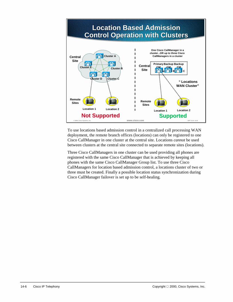
14-6 Cisco IP Telephony Copyright 2000, Cisco Systems, Inc.
© 2000, Cisco Systems, Inc. www.cisco.com CIPT V2.0—15-8
Cluster A
Cluster E
Cluster D Cluster C
Cluster B
Location Based AdmissionControl Operation with Clusters
Location Based AdmissionControl Operation with Clusters
Location 1 Location 2
One Cisco CallManager in acluster…OR up to three Cisco
CallManagers in a cluster
BA
Location 1 Location 2
PrimaryCM
BackupCM
“LocationsWAN Cluster”
RemoteSites
Not SupportedNot Supported
CentralSite
RemoteSites
CentralSite
SupportedSupported
C
BackupCM
To use locations based admission control in a centralized call processing WANdeployment, the remote branch offices (locations) can only be registered to oneCisco CallManager in one cluster at the central site. Locations cannot be usedbetween clusters at the central site connected to separate remote sites (locations).
Three Cisco CallManagers in one cluster can be used providing all phones areregistered with the same Cisco CallManager that is achieved by keeping allphones with the same Cisco CallManager Group list. To use three CiscoCallManagers for location based admission control, a locations cluster of two orthree must be created. Finally a possible location status synchronization duringCisco CallManager failover is set up to be self-healing.

Copyright 2000, Cisco Systems, Inc. Centralized Call Processing 14-7
© 2000, Cisco Systems, Inc. www.cisco.com CIPT V2.0—15-9
IP WAN
Hybrid—Large Campus Interactionwith Location Based Remote Sites
Location 1 Location 2
Locations BasedCentralized
Clusters
RemoteSites
CentralSiteLarge Campus Cluster
(10,000 Users)
Clusters Clusters NetworkedNetworkedvia H.323via H.323
Location 3 Location 42500 Users 2500 Users
H.323 gatekeeper for call admission control not required
because all CMs in campus
A
The figure above describes how a hybrid site of a large campus with locationbased remote sites can be designed. The large campus cluster and the locationsbased centralized clusters are networked via H.323 and the remote sites areregistered to one Cisco CallManager within a locations based cluster.
The following page describes the caveats when using location based calladmission.

14-8 Cisco IP Telephony Copyright 2000, Cisco Systems, Inc.
Caveats for Location Based Call Admission
© 2000, Cisco Systems, Inc. www.cisco.com CIPT V2.0—15-10
Caveats for Location BasedCall Admission
Caveats for Location BasedCall Admission
• Mobility of devices between locations is not possible• Calls are admitted based upon the availability of 24 kbps
of bandwidth• The amount of bandwidth specified can be
oversubscribed• CallManager 3.0 deployments of centralized call
processing are limited to hub and spoke topologies• Bandwidth should be dimensioned according to the
dedicated resources allocated on the smaller link• The IOS gatekeeper can only provide admission control
for calls between CallManagers in release 3.0(1)• If more than 20 users at remote site, install a Cisco
CallManager at that remote site
The following caveats should be considered when deploying locations-based calladmission control:
■ Mobility of devices between locations is not possible, as the CallManagerdecrements the specified location, not the physical location, of the device.
■ Calls are admitted based upon the availability of 24 kbps of bandwidth.G.729 calls consume 24 kbps and G.711 calls consume 80 kbps. Thus, ifmixed codecs are used over the WAN, all calls should be assumed toconsume 80 kbps and the bandwidth allocated accordingly. Where possible,a single codec should be configured for the WAN. In this case, thebandwidth allocated should be done so in n x 24 kbps increments for G.729or n x 80 kbps increments for G.711.
■ When a call is placed on hold, the bandwidth is released to the pool and canbe used by another call. When the original call is taken off hold, the amountof bandwidth specified can be oversubscribed. In this case the call is allowedto continue, but the low latency queue on the wide area link could beoversubscribed and voice quality might be compromised. To negate this risk,the configured size of the low latency queue should exceed the specifiedbandwidth on CallManager by a minimum of one call capacity for the codecspecified.
■ CallManager 3.0 deployments of centralized call processing are limited tohub and spoke topologies.

Copyright 2000, Cisco Systems, Inc. Centralized Call Processing 14-9
■ Where more than one circuit or virtual circuit exists to a spoke location, thebandwidth should be dimensioned according to the dedicated resourcesallocated on the smaller link.
■ The IOS gatekeeper can only provide admission control for calls betweenCallManagers in release 3.0(1). The gatekeeper cannot provide admissioncontrol between a CallManager and a remote IOS gateway. An examplewould be if a CallManager at one site wanted to call another site where thereis an IOS gateway connected to a PBX. The CallManager does not use E.164addresses in the ARQ when it queries the gatekeeper for admission.
■ If the remote site has more than 20 users, install a Cisco CallManager at thatremote site.

14-10 Cisco IP Telephony Copyright 2000, Cisco Systems, Inc.
Dial Plan Considerations
© 2000, Cisco Systems, Inc. www.cisco.com CIPT V2.0—15-12
Three Types of CallsThree Types of Calls
Router/GW
IP WAN
PSTNV
Location 1
IP WANRouter
IP WANRouter
CentralizedCallManager Cluster Site 2
Site 3
V
V
• Intra-locations calls• Inter-cluster calls• Local PSTN calls
Intra-location calls are generally made between IP phones and other devices suchas fax machines and analog phones connected to gateway devices based onMGCP or the skinny gateway protocol. As within a cluster, all devices registerwith a single CallManager so that the availability of all devices is known. Whena call is attempted, the outcome is one of the following:
■ The call succeeds.
■ A busy tone is issued due to the remote device being active.
■ A busy tone is issued due to insufficient WAN resources; a message mightalso be displayed on the device.
No configuration of a dial plan is required for intra-cluster calls in the majorityof cases.
Inter-cluster calls are made using H.323 and, with CallManager 3.0, inter-clustercalls can use alternative routing, including PSTN fallback. Between clustersconnected over a WAN, a gatekeeper is required for call admission control.
Each site can dial a single number to access the local PSTN. The same code canbe used for PSTN access and, based upon the partition and calling search space,a local gateway is selected.

Copyright 2000, Cisco Systems, Inc. Centralized Call Processing 14-11
Design Example
© 2000, Cisco Systems, Inc. www.cisco.com CIPT V2.0—15-13
Required PartitionsRequired Partitions
Intra-Cluster andLocal Gateway Access
Intra-Cluster andLocal Gateway Access
Partition Name Designated Devices Assigned to Partition
Cluster-X Users
PSTN gateway at Branch 3
All IP phones with-in the cluster
Cluster-X Hub PSTN Access PSTN gateway (s) at hub location
Cluster-X Branch 1 PSTN Access PSTN gateway at Branch 1
Cluster-X Branch 2 PSTN Access PSTN gateway at Branch 2
Cluster-X Branch 3 PSTN Access
Using the network diagram from the previous page, the partitions detailed inabove table would be configured to allow users to have access to either all intra-cluster locations or all intra-cluster locations and a local gateway.
The next thing that has to be defined is the calling search space. A table on thenext page defines the calling search spaces for the above defined partitions.

14-12 Cisco IP Telephony Copyright 2000, Cisco Systems, Inc.
© 2000, Cisco Systems, Inc. www.cisco.com CIPT V2.0—15-14
Calling Party Search Spaceand Partition AssignmentsCalling Party Search Spaceand Partition Assignments
Partitions Assigned to
Cluster-X Internal Only
Internal calls and PSTN callsthrough hub location gatewaysCluster-X Hub PSTN Access
Cluster-X Branch 1 PSTN Access
Cluster-X Branch 2 PSTN Access
Cluster-X Branch 3 PSTN Access
Calling Party Search Space
Cluster-X UsersDevices that can only makeinternal calls
Cluster-X Hub Unrestricted Cluster-X Users
Cluster-X Branch 1 Unrestricted Cluster-X Users
Cluster-X Users
Cluster-X Users
Cluster-X Branch 2 Unrestricted
Cluster-X Branch 2 Unrestricted
Internal calls and PSTN callsthrough Branch 1 location gateways
Internal calls and PSTN callsthrough Branch 2 location gateways
Internal calls and PSTN callsthrough Branch 3 location gateways
This represents perhaps the simplest example of the required configuration formulti-site WAN local call processing. The dial plan would consist essentially ofa single pattern for PSTN calls, typically a 9. The gateway traversed woulddepend entirely upon the calling devices partition and selected calling searchspace as detailed above.
Additional considerations would require a more ambitious dial plan. For a moredetailed dial plan refer to Chapter 11, “Dial Plan Architecture”.
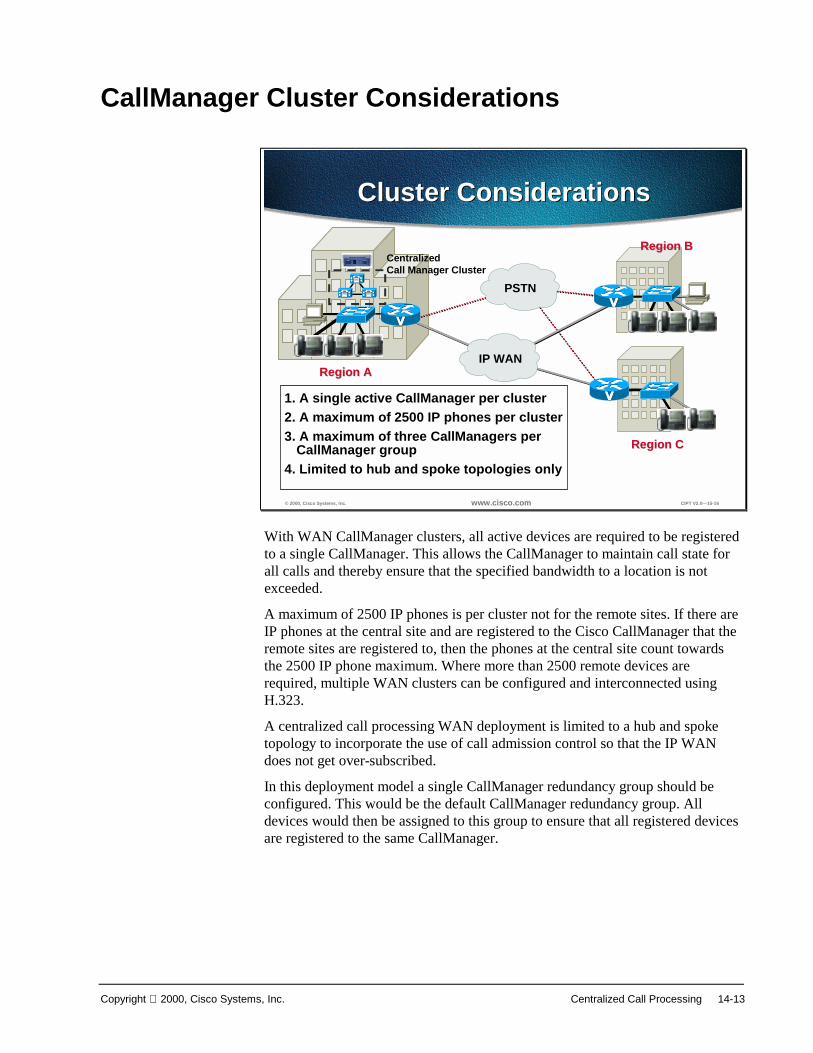
Copyright 2000, Cisco Systems, Inc. Centralized Call Processing 14-13
CallManager Cluster Considerations
© 2000, Cisco Systems, Inc. www.cisco.com CIPT V2.0—15-16
Cluster ConsiderationsCluster Considerations
PSTN
IP WANRegion ARegion A
Region BRegion B
Region CRegion C
CentralizedCall Manager Cluster
1. A single active CallManager per cluster2. A maximum of 2500 IP phones per cluster3. A maximum of three CallManagers per
CallManager group4. Limited to hub and spoke topologies only
With WAN CallManager clusters, all active devices are required to be registeredto a single CallManager. This allows the CallManager to maintain call state forall calls and thereby ensure that the specified bandwidth to a location is notexceeded.
A maximum of 2500 IP phones is per cluster not for the remote sites. If there areIP phones at the central site and are registered to the Cisco CallManager that theremote sites are registered to, then the phones at the central site count towardsthe 2500 IP phone maximum. Where more than 2500 remote devices arerequired, multiple WAN clusters can be configured and interconnected usingH.323.
A centralized call processing WAN deployment is limited to a hub and spoketopology to incorporate the use of call admission control so that the IP WANdoes not get over-subscribed.
In this deployment model a single CallManager redundancy group should beconfigured. This would be the default CallManager redundancy group. Alldevices would then be assigned to this group to ensure that all registered devicesare registered to the same CallManager.

14-14 Cisco IP Telephony Copyright 2000, Cisco Systems, Inc.
DSP Resource Provisioning for Transcoding andConferencing
© 2000, Cisco Systems, Inc. www.cisco.com CIPT V2.0—15-18
DSP Resource AllocationDSP Resource Allocation
Cluster XLocation 2
PrimaryCM
BackupCM
Centralized CallProcessingCluster X
Cluster XLocation 1
MTP
Conf
MTP
Conf
Centralized call processing is typically done in environments where theprovisioning of dedicated call processing at each site is not cost effective or isadministratively unacceptable. The benefits of such a deployment model are itscentral administration and low cost when spread across many sites. Digitalsignal processing (DSP) resources are required for transcoding and conferencingof calls. These resources are dedicated on a per CallManager basis and must belocated at the aggregation site.
The number of resources allocated is based upon the requirements fortranscoding to voice mail and transcoding to G.711 for other applications such asconferencing. These numbers are calculated based upon the ratio of users tovoice mail ports and the volume of conference calls placed. In cases where theplacement of resources per CallManager is deemed cost prohibitive, theresources could be statically moved in the event of failure of the primaryCallManager within the WAN cluster.

Copyright 2000, Cisco Systems, Inc. Centralized Call Processing 14-15
© 2000, Cisco Systems, Inc. www.cisco.com CIPT V2.0—15-19
Router/GW Router/GW
Call ManagerCluster
IP WAN
uOneGateserver
Transcoding
DSP
Transcoding andConferencing
Transcoding andConferencing
Router/GW Router/GW
Call ManagerCluster
IP WAN
uOneGateserver
Conferencing
DSP
Compressed Call LegG.711 Call Leg
The top part of the figure above shows a centralized transcoding resourceproviding conversion between G.729a or G.723.1 and G.711 when a call thatwas initially placed at G.729a or G.723.1 rolls to voice mail, which is a G.711only application.
Conferencing poses another example of a G.711 only application. Consequently,if a party who can only traverse the WAN using a low bit rate codec wants tomake a conference call, the call will be transcoded to G.711 in the conferencingresource of the DSP.

14-16 Cisco IP Telephony Copyright 2000, Cisco Systems, Inc.

Copyright 2000, Cisco Systems, Inc. Centralized Call Processing 14-17
SummaryThis section summarizes the concepts you learned in this chapter.
© 2000, Cisco Systems, Inc. www.cisco.com CIPT V2.0—15-20
SummarySummary
• Locations construct is used for WANdeployments that use centralized callprocessing.
• CallManager 3.0 deployments of centralizedcall processing are limimted to hub and spoketopologies.
• A maximum of 2500 IP phones is per cluster,and not for the remote sites.
Locations construct is used for WAN deployments that use centralized callprocessing and is limited to a hub and spoke topology.
A maximum of 2500 IP phones is per cluster and not for the remote sites. If thereare IP phones at the central site and they are registered to the Cisco CallManagerthat the remote sites are registered to, then the phones at the central site counttoward the 2500 IP phone maximum. Where more than 2500 remote devices arerequired, multiple WAN clusters can be configured and interconnected usingH.323.

14-18 Cisco IP Telephony Copyright 2000, Cisco Systems, Inc.
Review QuestionsAnswer the following questions.
© 2000, Cisco Systems, Inc. www.cisco.com CIPT V2.0—15-21
Review QuestionsReview Questions
1. In a centralized call processing WANdeployment, how many Cisco CallManagerscan the remote offices be registered to?
2. What keeps track of the current amount ofbandwidth consumed by inter-locationvoice calls?
3. DSP resources provide transcoding andconferencing services for the remote sites.Where are those resources located?
Q1) There can be up to five Cisco CallManagers in a cluster. In a centralized callprocessing WAN deployment, how many Cisco CallManagers can the remoteoffices be registered to?
Q2) IP WAN bandwidth needs to be controlled. What keeps track of the currentamount of bandwidth consumed by inter-location voice calls?
Q3) DSP resources provide transcoding and conferencing services for the remotesites. Where is the physical location of these resources?

Copyright 2000, Cisco Systems, Inc. Centralized Call Processing 14-19
15
Troubleshooting a CIPTSolution
OverviewThis chapter explains in detail the tools and utilities to troubleshoot a Cisco IPTelephony solution. The case study will discuss in detail a unique call flow.Understanding the information provided in this chapter will help users find aresolution quicker, as well as to isolate most of their issues. This chapter mightnot resolve all your problems but it will at least give the user a very goodunderstanding of the troubleshooting IP telephony issues using the CiscoCallManager 3.0 and IOS gateways and gatekeeper.
The following topics are included in this chapter:
■ Objectives
■ Tools and Utility for Troubleshooting
■ Case Study—Intra Cluster IP Phone to IP Phone Calls
■ Laboratory Exercise
■ Summary
■ Review Question
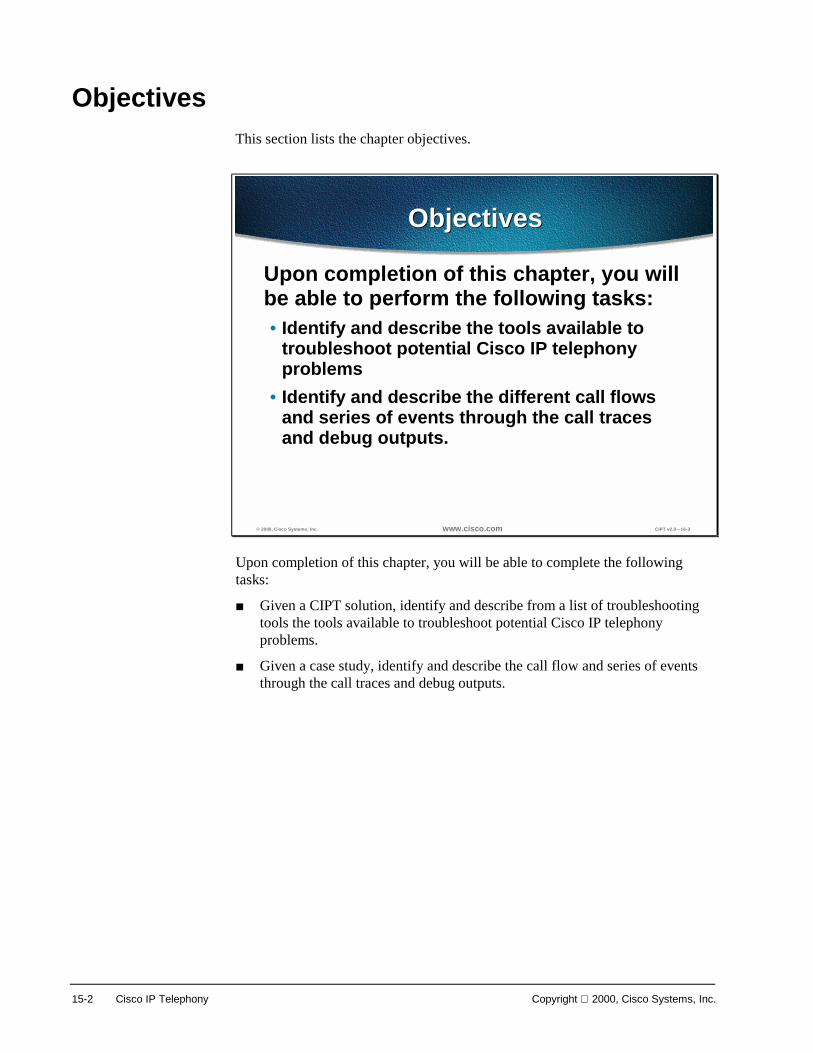
15-2 Cisco IP Telephony Copyright 2000, Cisco Systems, Inc.
ObjectivesThis section lists the chapter objectives.
© 2000, Cisco Systems, Inc. www.cisco.com CIPT v2.0—16-3
ObjectivesObjectives
Upon completion of this chapter, you willbe able to perform the following tasks:• Identify and describe the tools available to
troubleshoot potential Cisco IP telephonyproblems
• Identify and describe the different call flowsand series of events through the call tracesand debug outputs.
Upon completion of this chapter, you will be able to complete the followingtasks:
■ Given a CIPT solution, identify and describe from a list of troubleshootingtools the tools available to troubleshoot potential Cisco IP telephonyproblems.
■ Given a case study, identify and describe the call flow and series of eventsthrough the call traces and debug outputs.

Copyright 2000, Cisco Systems, Inc. Troubleshooting a CIPT Solution 15-3
Tools and Utilities for Troubleshooting
© 2000, Cisco Systems, Inc. www.cisco.com CIPT v2.0—16-4
Tools and UtilitiesTools and Utilities
• Cisco CallManager Administration• Performance Monitor• Event log• Local log files• SDL trace• Trace utility
The tools and utilities listed below will aid in troubleshooting a Cisco IPtelephony solution:
■ Cisco CallManager administration—The Cisco CallManager AdministrationWindow is the first location to obtain useful troubleshooting information.
■ Performance monitor—Windows NT server application that allowsmonitoring of a variety of system variables in real time.
■ Event log—Displays system, security and application events for theWindows NT Server.
■ Local log files—Displays IP address, TCP handle, device name or the timestamp that can be used to monitor the occurrence of request or thedisposition of the request.
■ SDL trace—Informs the developer engineer that the code is workingproperly or to find a cause of an error.
■ Trace utility—Interface in the Cisco CallManager administration that is usedto set all the preferences to get the specific information that is required bythe user.

15-4 Cisco IP Telephony Copyright 2000, Cisco Systems, Inc.
Cisco CallManager Administration
© 2000, Cisco Systems, Inc. www.cisco.com CIPT v2.0—16-5
Cisco CallManagerAdministration
Details button on theAbout page shows
version and databaseinformation
Details button on theAbout page shows
version and databaseinformation
The Cisco CallManager administration has eight categories, each having asimplified pull down menu. These pull down menus have all the configurablefeatures for Cisco CallManager.
The Cisco CallManager Administration window is the first location for a user toobtain useful troubleshooting information. If the Details button is pushed,information such as the Cisco CallManager system version, administrationversion and database information will be displayed. This is the first piece ofinformation that should be obtained when troubleshooting any issues with CiscoCallManager. A more detailed explanation of CCM 3.0 administration isavailable at the following location:
http://lbj.cisco.com/push_targets1/ucdit/cc/td/doc/product/voice/call_mgr/3_0/admin_gd/index.htm

Copyright 2000, Cisco Systems, Inc. Troubleshooting a CIPT Solution 15-5
Performance Monitor
© 2000, Cisco Systems, Inc. www.cisco.com CIPT v2.0—16-6
Performance MonitorPerformance Monitor
Performance Monitor is the first step for troubleshooting CIPT solution issues.Performance Monitor is a Windows NT server application that lets you monitora variety of system variables in real time. For example, you can monitor thenumber of calls in progress at any time, or the number of calls currently passingthrough a specific gateway.
Performance Monitor shows both general and CCM 3.0 specific statusinformation in real time.
Do the following to view the Performance Monitor window:
1. Click the Start button on the Task bar.
2. Choose Program.
3. Choose Administrative Tools (Common).
4. Choose Performance Monitor.
The Performance Monitor must be customized to view the Cisco CallManagerrelated parameters that need to be monitored. Choose the object, counter, andinstance you want to include. Open the View menu and click Report to open thePerformance Monitor window. Click the Add button to add a new category("Object") to the report. The Add to Report dialog box is displayed.
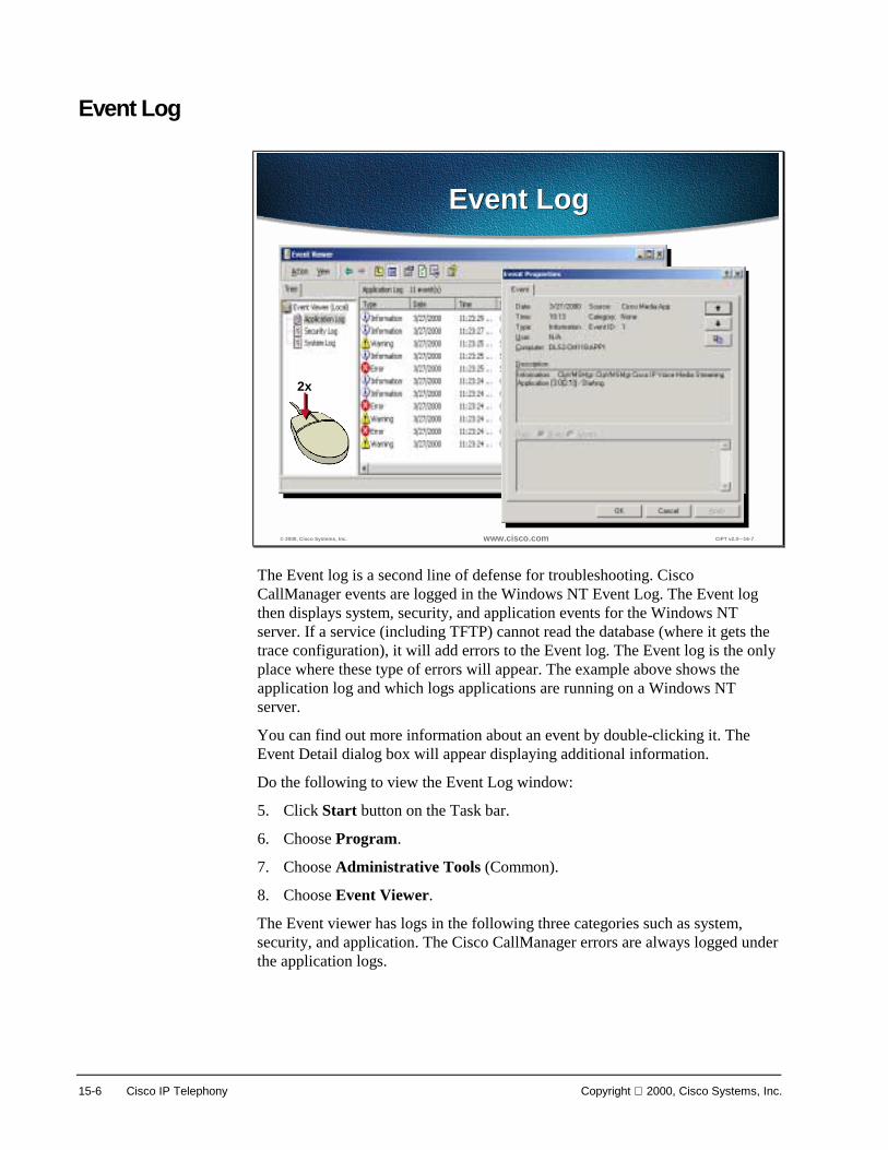
15-6 Cisco IP Telephony Copyright 2000, Cisco Systems, Inc.
Event Log
© 2000, Cisco Systems, Inc. www.cisco.com CIPT v2.0—16-7
Event LogEvent Log
2x
The Event log is a second line of defense for troubleshooting. CiscoCallManager events are logged in the Windows NT Event Log. The Event logthen displays system, security, and application events for the Windows NTserver. If a service (including TFTP) cannot read the database (where it gets thetrace configuration), it will add errors to the Event log. The Event log is the onlyplace where these type of errors will appear. The example above shows theapplication log and which logs applications are running on a Windows NTserver.
You can find out more information about an event by double-clicking it. TheEvent Detail dialog box will appear displaying additional information.
Do the following to view the Event Log window:
5. Click Start button on the Task bar.
6. Choose Program.
7. Choose Administrative Tools (Common).
8. Choose Event Viewer.
The Event viewer has logs in the following three categories such as system,security, and application. The Cisco CallManager errors are always logged underthe application logs.

Copyright 2000, Cisco Systems, Inc. Troubleshooting a CIPT Solution 15-7
Local Log Files
© 2000, Cisco Systems, Inc. www.cisco.com CIPT v2.0—16-8
Local Log FilesLocal Log Files
• IP address or device name can be usedto find the occurrence of the request orthe disposition of that request
• Device name can be tracked• Device pool and model can be tracked• C++ class and routine name are
included with most trace lines
Local log files provide the greatest level of detailed information. Whenreviewing the local log files, IP address, TCP handle, device name or the timestamp can be used to monitor the occurrence of request or the disposition of therequest. This device name could be tracked back to the building of the file,which shows the device pool and model. The device pool and model can betracked back to the building of the configuration file prototype, which will listthe network address of the call managers and the TCP connection port.
When observing the traces, notice that C++ class and routine names are includedwith most trace lines. Most routines associated with the serving of a particularrequest, include the thread id in a standard format.
These traces will be explained in detail in Case Study #1.

15-8 Cisco IP Telephony Copyright 2000, Cisco Systems, Inc.
SDL Trace
© 2000, Cisco Systems, Inc. www.cisco.com CIPT v2.0—16-9
SDL TraceSDL Trace
This trace informs the developer engineer (DE) that the code is working properlyor to find a cause of an error. Most of this information would only make sense toa DE. While working with TAC and a DE, if the TAC engineer requests a SDLtrace, it is your responsibility to enable the SDL trace and provide it to the TACengineer. SDL traces can be directed to local files, NT event log, and CiscoWorks.
SDL trace provides a C interface to trace and alarms. Alarms are used to informthe administrator for unexpected events, such as being unable to access a file,database, Winsock or being unable to allocate other operating system resources.SDL traces could be turned on through the service parameter configuration. Thefigure above is the snap shot of the service parameter window when the SDLtraces are being turned on. Always keep in mind that these traces are only turnedon when requested by the TAC engineer. Also observe the different valueschosen to turn on the SDL trace in the snap shot below.
Once the SDL traces are turned on, the next step is to collect and see thesetraces. If the traces are being sent to the local files, then the following snapshotwould tell you where to find these traces. The path is ProgramFiles>Cisco>Services and can be observed in the snap shot above. The snapshotof these traces will be explained in the case studies in upcoming sections.
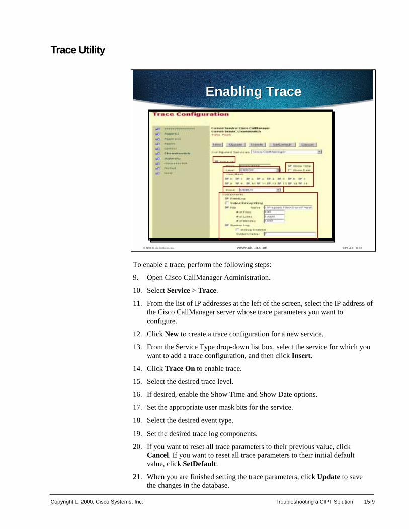
Copyright 2000, Cisco Systems, Inc. Troubleshooting a CIPT Solution 15-9
Trace Utility
© 2000, Cisco Systems, Inc. www.cisco.com CIPT v2.0—16-10
Enabling TraceEnabling Trace
Select OneSelect One
To enable a trace, perform the following steps:
9. Open Cisco CallManager Administration.
10. Select Service > Trace.
11. From the list of IP addresses at the left of the screen, select the IP address ofthe Cisco CallManager server whose trace parameters you want toconfigure.
12. Click New to create a trace configuration for a new service.
13. From the Service Type drop-down list box, select the service for which youwant to add a trace configuration, and then click Insert.
14. Click Trace On to enable trace.
15. Select the desired trace level.
16. If desired, enable the Show Time and Show Date options.
17. Set the appropriate user mask bits for the service.
18. Select the desired event type.
19. Set the desired trace log components.
20. If you want to reset all trace parameters to their previous value, clickCancel. If you want to reset all trace parameters to their initial defaultvalue, click SetDefault.
21. When you are finished setting the trace parameters, click Update to savethe changes in the database.

15-10 Cisco IP Telephony Copyright 2000, Cisco Systems, Inc.
© 2000, Cisco Systems, Inc. www.cisco.com CIPT v2.0—16-11
Trace LevelsTrace Levels
• Error• Special• State Transition• Significant• Entry/Exit• Arbitrary• Detailed
The table below lists the available trace levels. The error level provides the leastamount of trace information, and the detailed level provides the most. The levelsare cumulative, which means that a more detailed level includes all sameinformation as the level below it plus some additional information.
Trace Levels
Level Description
Error Traces alarm conditions and events.
Special Traces all Error conditions plus process and device initialization messages.
State Transition Traces all Special conditions plus subsystem state transitions that occur duringnormal operation.
Significant Traces all State Transition conditions plus media events that occur duringnormal operation.
Entry/Exit This trace level is not currently used.
Arbitrary Traces all Significant conditions plus low-level debugging information.Do not use this trace level during normal operation.
Detailed Traces all Arbitrary conditions plus detailed debugging information.Do not use this trace level during normal operation.
You can enable the Show Date and Show Time options to record the date andtime of each trace event.

Copyright 2000, Cisco Systems, Inc. Troubleshooting a CIPT Solution 15-11
© 2000, Cisco Systems, Inc. www.cisco.com CIPT v2.0—16-12
User Mask Flag DefinitionsUser Mask Flag DefinitionsUser Mask BitsMask Bits Type of Trace Enabled by This Bit
0 Protocol layer 1 information.1 Protocol layer 2 information.2 Digital gateway information.3 Analog gateway information.4 Primary Rate Interface (PRI) information.5 Skinny Station protocol information.6 Message translation information for ISDN messages.7 Media Termination Point (MTP) information.8 H.225 and Gatekeeper information.9 Gateway traces (used in conjunction with bits 2, 3, and 4)10 Database signaling information.11 Subsystem information not covered by one of the other user mask bits.12 Conference bridge information.13 MGCP gateway information.14-15 Not used.
The user mask is a series of flags, or bits, that enable and disable specific typesof trace information. As you turn the bits on and off, the value in the Mask fieldchanges. The name and definition of each user mask flag is on the followingpage.
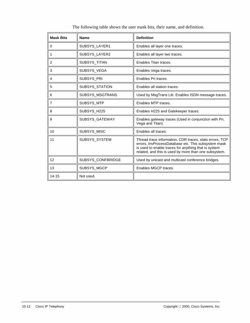
15-12 Cisco IP Telephony Copyright 2000, Cisco Systems, Inc.
The following table shows the user mask bits, their name, and definition.
Mask Bits Name Definition
0 SUBSYS_LAYER1 Enables all layer one traces.
1 SUBSYS_LAYER2 Enables all layer two traces.
2 SUBSYS_TITAN Enables Titan traces.
3 SUBSYS_VEGA Enables Vega traces.
4 SUBSYS_PRI Enables Pri traces.
5 SUBSYS_STATION Enables all station traces.
6 SUBSYS_MSGTRANS Used by MsgTrans Lib. Enables ISDN message traces.
7 SUBSYS_MTP Enables MTP traces.
8 SUBSYS_H225 Enables H225 and Gatekeeper traces.
9 SUBSYS_GATEWAY Enables gateway traces (Used in conjunction with Pri,Vega and Titan).
10 SUBSYS_MISC Enables all traces.
11 SUBSYS_SYSTEM Thread trace information, CDR traces, stats errors, TCPerrors, InvProcessDatabase etc. This subsystem maskis used to enable traces for anything that is systemrelated, and this is used by more than one subsystem.
12 SUBSYS_CONFBRIDGE Used by unicast and multicast conference bridges.
13 SUBSYS_MGCP Enables MGCP traces.
14-15 Not used.

Copyright 2000, Cisco Systems, Inc. Troubleshooting a CIPT Solution 15-13
© 2000, Cisco Systems, Inc. www.cisco.com CIPT v2.0—16-13
Trace LogTrace Log
• EventLog• Output Debug String• File• System Log
Creating a large number of trace files, or lettinga single trace file grow too large, can severely
degrade the performance of your system.
Creating a large number of trace files, or lettinga single trace file grow too large, can severely
degrade the performance of your system.
The following table shows the components of the Trace log.
Component Description
EventLog Enable this option to send trace information to the Windows 2000 EventLog.
Output DebugString
This option is for Cisco development use only. Do not enable this option unless instructed to do so byCisco Technical Assistance Center (TAC).
File Enable this option to store trace information in a file. You can also set the following file parameters:
■ Name is the fully qualified path name of the trace file. Each service requires a unique trace filename. Cisco recommends that you leave the file names set to their default values.
■ # of Files specifies the total number of trace files for a given service. A sequence number isautomatically appended to the file name to indicate which file it is. When the last file in thesequence is full, the trace data begins writing over the first again.
■ # of Lines specifies the maximum number of lines of data stored in each trace file.
■ # of Minutes specifies the maximum number of minutes worth of data stored in each trace file.
When the trace data exceeds either the maximum number of lines or the maximum number of minutesfor one file, that file is closed and the remaining trace data is written to the next file in the sequence.For example, you can set up trace files to store a full week of data, with one day of data in each file. Todo this, you can set the number of files to 7, the number of minutes to 1440 (one day), and number oflines to a large value such as 10000.
System Log Enable this option to send trace information to the Cisco Syslog Collector.The system log parameters are:
Debug enabled causes all trace data to be sent to the Cisco syslog collector. If you do not enable thisoption, only alarm (Error) traces are sent to the Cisco syslog collector.
System server is the name of the Cisco syslog collector. Do not change this field unless instructed todo so by Cisco Technical Assistance Center (TAC).

15-14 Cisco IP Telephony Copyright 2000, Cisco Systems, Inc.
© 2000, Cisco Systems, Inc. www.cisco.com CIPT v2.0—16-14
Minimum Alarm TracingMinimum Alarm Tracing
• Enable Trace On• Set the trace level to Error• Enable the appropriate user mask bits for each
service, as described in User Mask Bits Table• Set the event type to Error• Enable EventLog
In general, it is best to start with a small amount of tracing so that systemresources are not overloaded by the trace data. If the initial traces are notsufficient for your purposes, you can gradually increase the level of tracing untilyou get the desired data. If system performance begins to degrade during tracing,decrease the trace level until the performance returns to normal.
During normal system operation, it is customary to trace alarm conditions and torespond to them as quickly as possible. Alarm tracing is considered to be theminimum level of tracing for a fully operational system. To configure thisminimum level of alarm tracing, set the trace parameters as follows for eachservice on each Cisco CallManager in the cluster:
■ Enable Trace On.
■ Set the trace level to Error.
■ Enable the appropriate user mask bits for each service, as described in theUser Mask Bits Table.
■ Set the event type to Error.
■ Enable EventLog.

Copyright 2000, Cisco Systems, Inc. Troubleshooting a CIPT Solution 15-15
Case Study—Intra Cluster IP Phone to IP Phone CallsThis section discusses a case study of an Intra Cluster IP Phone to IP Phonecalls.
© 1999, Cisco Systems, Inc. www.cisco.com CIPT—Chapter 16-18
IP Phone to IP Phone(Intra Cluster)
IP Phone to IP Phone(Intra Cluster)
• IP phone initialization process• Skinny station registration messages• IP phone to IP phone call flow within
a cluster• IP phone to IP phone call flow
skinny messages• IP phone registration and call flow
messages through the Cisco CallManager traces
This case study would discuss in detail the call flow between two IP phoneswithin a cluster, called an intra cluster call. This case study will also focus onCisco CallManager and IP phone initialization, registration and keep aliveprocesses followed by a detailed explanation of a intra cluster call flow. We willexplain all these processes by using trace utility and tools discussed in previoussection.

15-16 Cisco IP Telephony Copyright 2000, Cisco Systems, Inc.
© 2000, Cisco Systems, Inc. www.cisco.com CIPT v2.0—16-16
IOS Gatekeeper
CCM3
IP WAN
Case Study TopologyCase Study Topology
CCM4
172.16.70.245 172.16.70.243
172.16.70.241172.16.70.225
CCM1 CCM2
172.16.70.228 172.16.70.229
Cluster 1 Cluster 2
Zone 1 Zone 2
RAS
T1/CAS
T1/PRI
PSTN
The diagram above describes the sample topology for this case study. In thediagram we have two clusters named cluster 1 and cluster 2. The two CiscoCallManagers in cluster 1 are called CCM3 and CCM4, whereas in cluster 2 thetwo Cisco CallManagers are named CCM1 and CCM2. All the traces collectedfor this case study are from CCM1 that is located in Cluster 2. The call flow isbased on the two IP Phones in cluster 2. The IP addresses of these two IP phonesare 172.16.70.230 (directory number 1000) and 172.16.70.231 (directory number1001) respectively.

Copyright 2000, Cisco Systems, Inc. Troubleshooting a CIPT Solution 15-17
© 1999, Cisco Systems, Inc. www.cisco.com CIPT—Chapter 16-19
IP Phone Initialization ProcessIP Phone Initialization ProcessGet IP address, mask, DNS, etc.
•Static or DHCPGet TFTP server address
•Static address•Option 150 (single IP address)•Option 66 (first IP address or DNS name)•Look up CiscoCM1.your.domain
Get configuration from CallManager TFTP*•List of up to three CallManagers•Region info and keyboard template•Version of code to run
Get new code (one time only)Register with CallManager
1
3
2
4
5
DHCPDNS
CallManagerTFTP
13
245
*Use configuration in Flash after timeout
Useanyone
IP Phone Initialization Process1. When a telephone is plugged into an Ethernet jack, assuming the
prerequisite infrastructure and a CallManager, the first thing that will happenis the telephone will request an IP address from a Dynamic HostConfiguration Protocol (DHCP) server. In general, this is the recommendedmode of operation. Static addressing can be supplied to the telephone, andyou can enter the IP address manually, but this would prevent mobility.
2. As part of that DHCP request, when an IP address is supplied to thetelephone, it is also possible to supply the address of the TFTP server, or theCallManager from which the telephone will get its configuration. Once again,the TFTP server address could be specified manually but this would limitadds, moves, and changes and remove some of the benefits. This TFTP serveraddress can be given in several forms: either Option 150 or Option 66 or theBootstrap Protocol (BOOTP).
3. Once that address has been given, the phone will register itself with theCallManager and download its configuration, which can contain a list of upto five CallManagers that the telephone can use for call control. This createsan extremely resilient system. The Phone gets its region information and alsothe features or functionality that each of the keys will produce.
4. The phone receives any new code it is to run. If, for example, the firmwareor the code that each telephone runs is changed, this can be added to theCallManager. Once restarted, each telephone will automatically reload thatcode. The telephones can be configured to auto register.
5. An administrator rolling out the phones would plug each one in and thenassign a number. New phone entries will appear by Media Access Control(MAC) address, which is how the CallManager ties the actual instrument to atelephone number. An alternate, not the normal operation, would occur when

15-18 Cisco IP Telephony Copyright 2000, Cisco Systems, Inc.
you plug in the telephone; CallManager would automatically give thattelephone a line number. However, this would make things like directoriesvery difficult to set up.
* Use configuration in Flash after timeout.

Copyright 2000, Cisco Systems, Inc. Troubleshooting a CIPT Solution 15-19
© 1999, Cisco Systems, Inc. www.cisco.com CIPT—Chapter 16-20
IP Phone Initialization Process Trace
IP Phone Initialization Process Trace
The following snapshot of Sniffer trace summarizes the phone initializationprocess: Please keep in mind that this trace is not taken for this Sampletopology, but does give you a good idea of the series of events that occur duringthe IP phone boot up process.

15-20 Cisco IP Telephony Copyright 2000, Cisco Systems, Inc.
Skinny Station Registration Process
© 1999, Cisco Systems, Inc. www.cisco.com CIPT—Chapter 16-22
Skinny Station Registration Messages
Skinny Station Registration Messages
Cisco CallManager
Stateless Client
Station Register
Station Media Port
Station Capabilities Req
Station Button Template Req
Station Version Req
Station Time Date Req
Station Reset
Station Register Ack
Station Version Res
Station Button Template
Station Define Time Date
Additional Optional Messages
Station Capabilities Res
The registration process allows skinny station (IP Phone) to inform CiscoCallManager of its existence and to make calling possible. The following figureshows the different messages that are exchanged between the IP phone and theCisco CallManager.

Copyright 2000, Cisco Systems, Inc. Troubleshooting a CIPT Solution 15-21
The primary messages in the skinny station registration process are describedbelow.
■ Station Register: This message is used by the station to announce itsexistence to the controlling Cisco CallManager.
■ Station Reset: This message is used by the CCM to command the client toreset its processes.
■ Station IP Port: The Station IP Port message is used by the station toprovide to the CALLMANAGER, the UDP port to be used with the RPTstream.
■ Station Register Acknowledge: This message is used by the CALLMANAGER to acknowledge the registration of a client.
OR
■ Station Register Reject: This message is used by the CALL MANAGER toreject a registration attempt from the indicated phone.
char text[StationMaxDisplayTextSize];
};
Where:
text is a character string, of a maximum length of 33 bytes, containing atextual description of the reason that registration is rejected.
■ Station Capabilities Request: This message is used by the CALLMANAGER to request the current capabilities of the client. Thesecapabilities includes compression standard and other H323 capabilities.
■ Station Version Request: This message is used by the station to request theversion number of the software load for the station.
■ Station Version Response: This message is used to inform the client of theversion number for the software it should be using.
■ Station Capabilities Response: This message is used to respond to a StationCapabilities Request message from the CALLMANAGER. Thesecapabilities are cached in the CALLMANAGER and used to negotiateterminal capabilities with an H.323 compliant Terminal.
■ Station Button Template Request: This message is used by the station torequest the button template definition for that specific terminal or Phone.
■ Station Button Template Response: This message is used to update thebutton template information contained in the client.
■ Station Time Date Request: This message is used by the station to requestthe current date and time for internal usage and for displaying as a textstring.
■ Station Define Time and Date: This message is used to provide the date andtime information to the client. It provides for time synchronization for theclients.

15-22 Cisco IP Telephony Copyright 2000, Cisco Systems, Inc.
IP Phone to IP Phone Call Flow Within a Cluster
© 1999, Cisco Systems, Inc. www.cisco.com CIPT—Chapter 16-23
CallManagerASecondary
CallManager
1000 Calls 1001CallManager Cluster
1000 1001RTP Stream
SkinnySkinny
Intra ClusterControl Protocol
Registered CallManager
IP Phone to IP Phone Call Flow within a Cluster
IP Phone to IP Phone Call Flow within a Cluster
This section describes an IP phone (1000) calling another IP phone (1001)within the same cluster. The cluster is a group of Call Managers having onecommon Publisher SQL database and many Subscriber SQL databases.
In our sample topology, CCM1 is publisher and CCM2 is subscriber. The two IPPhones (1000 and 1001) are registered respectively to CCM1 and CCM2. Thecall flow is shown in the diagram above. The two CallManagers within a clustercommunicate with each other using intra cluster control protocol (ICCP). WhenIP phone goes off-hook, it opens a control skinny session (tcp is underlyingprotocol) with the CCM. After call control signaling is established between twoIP phones and their respective call managers, the RTP stream start flowingdirectly between the two phones as shown in the diagram below. The skinny callflow messages for this intra-cluster call are explained in next section.
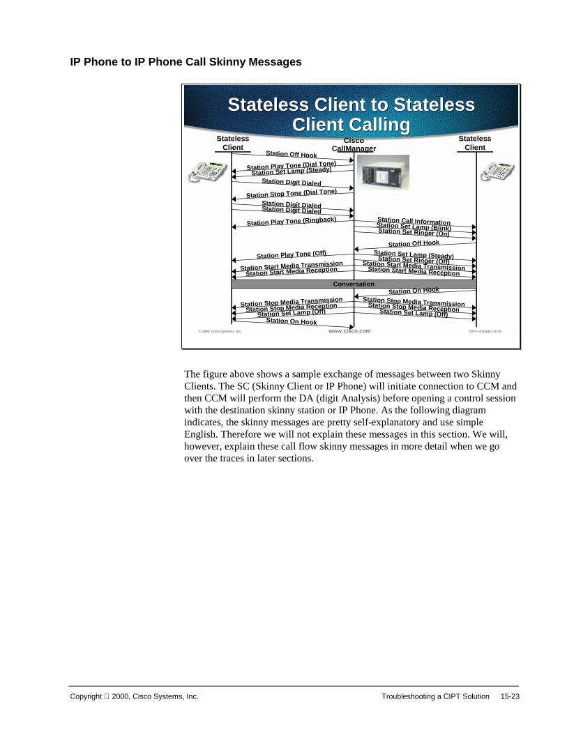
Copyright 2000, Cisco Systems, Inc. Troubleshooting a CIPT Solution 15-23
IP Phone to IP Phone Call Skinny Messages
© 1999, Cisco Systems, Inc. www.cisco.com CIPT—Chapter 16-24
Stateless Client to Stateless Client Calling
Stateless Client to Stateless Client Calling
Stateless Client
Cisco CallManager
Stateless Client
Station Off Hook
Station Digit Dialed
Station Play Tone (Dial Tone)Station Set Lamp (Steady)
Station Stop Tone (Dial Tone)
Station Digit DialedStation Digit Dialed
Station Play Tone (Ringback) Station Call InformationStation Set Ringer (On)Station Set Lamp (Blink)
Station Off Hook
Station Set Ringer (Off)Station Start Media TransmissionStation Start Media TransmissionStation Start Media ReceptionStation Start Media Reception
Station Set Lamp (Steady)Station Play Tone (Off)
ConversationStation On Hook
Station Stop Media TransmissionStation Stop Media TransmissionStation Stop Media ReceptionStation Stop Media Reception
Station Set Lamp (Off) Station Set Lamp (Off)Station On Hook
The figure above shows a sample exchange of messages between two SkinnyClients. The SC (Skinny Client or IP Phone) will initiate connection to CCM andthen CCM will perform the DA (digit Analysis) before opening a control sessionwith the destination skinny station or IP Phone. As the following diagramindicates, the skinny messages are pretty self-explanatory and use simpleEnglish. Therefore we will not explain these messages in this section. We will,however, explain these call flow skinny messages in more detail when we goover the traces in later sections.
15-24 Cisco IP Telephony Copyright 2000, Cisco Systems, Inc.
Cisco CallManager Trace through the Trace UtilityTroubleshooting different events using Cisco CallManager Trace through theTrace Utility.
© 1999, Cisco Systems, Inc. www.cisco.com CIPT—Chapter 16-25
CCM Trace Through the Trace Utility
CCM Trace Through the Trace Utility
• Initialization Process Trace• Registration Process Trace• Keepalive Process Trace• Intra Cluster Call Flow Trace
Trace utility is a very effective troubleshooting tool. Trace can be done to helptrouble shoot during different processes and call flows in a CIPT solution. Thepath to the trace files is; My Computer>Program files>Cisco>Trace.
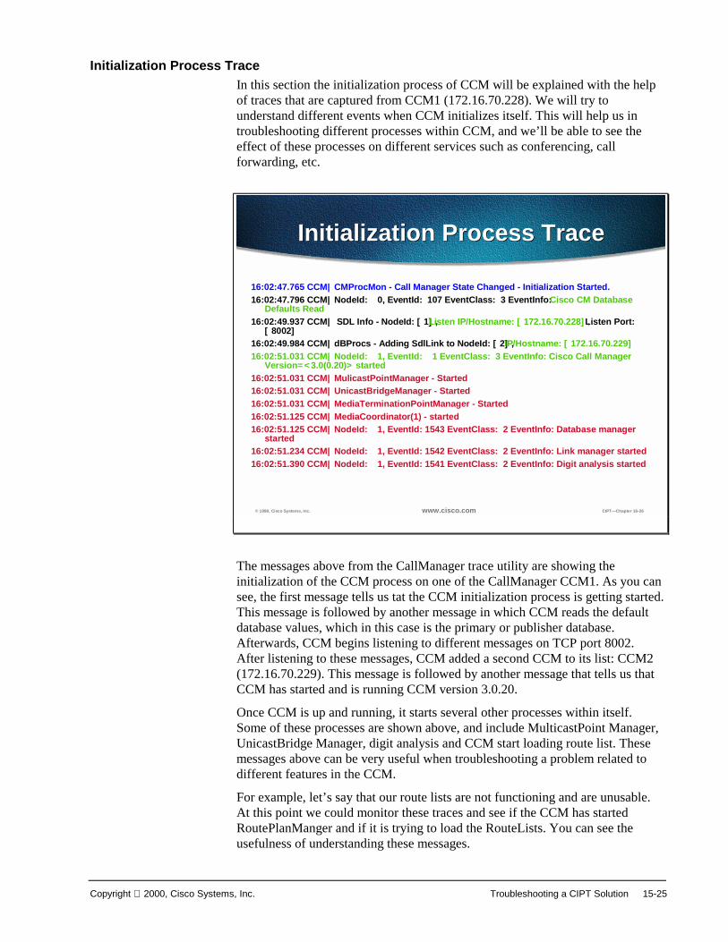
Copyright 2000, Cisco Systems, Inc. Troubleshooting a CIPT Solution 15-25
Initialization Process TraceIn this section the initialization process of CCM will be explained with the helpof traces that are captured from CCM1 (172.16.70.228). We will try tounderstand different events when CCM initializes itself. This will help us introubleshooting different processes within CCM, and we’ll be able to see theeffect of these processes on different services such as conferencing, callforwarding, etc.
© 1999, Cisco Systems, Inc. www.cisco.com CIPT—Chapter 16-26
Initialization Process TraceInitialization Process Trace
16:02:47.765 CCM|CMProcMon - Call Manager State Changed - Initialization Started.16:02:47.796 CCM|NodeId: 0, EventId: 107 EventClass: 3 EventInfo: Cisco CM Database
Defaults Read16:02:49.937 CCM| SDL Info - NodeId: [1], Listen IP/Hostname: [172.16.70.228],Listen Port:
[8002]16:02:49.984 CCM|dBProcs - Adding SdlLink to NodeId: [2], IP/Hostname: [172.16.70.229]16:02:51.031 CCM|NodeId: 1, EventId: 1 EventClass: 3 EventInfo: Cisco Call Manager
Version=<3.0(0.20)> started16:02:51.031 CCM|MulicastPointManager - Started16:02:51.031 CCM|UnicastBridgeManager - Started16:02:51.031 CCM|MediaTerminationPointManager - Started16:02:51.125 CCM|MediaCoordinator(1) - started16:02:51.125 CCM|NodeId: 1, EventId: 1543 EventClass: 2 EventInfo: Database manager
started16:02:51.234 CCM|NodeId: 1, EventId: 1542 EventClass: 2 EventInfo: Link manager started16:02:51.390 CCM|NodeId: 1, EventId: 1541 EventClass: 2 EventInfo: Digit analysis started
The messages above from the CallManager trace utility are showing theinitialization of the CCM process on one of the CallManager CCM1. As you cansee, the first message tells us tat the CCM initialization process is getting started.This message is followed by another message in which CCM reads the defaultdatabase values, which in this case is the primary or publisher database.Afterwards, CCM begins listening to different messages on TCP port 8002.After listening to these messages, CCM added a second CCM to its list: CCM2(172.16.70.229). This message is followed by another message that tells us thatCCM has started and is running CCM version 3.0.20.
Once CCM is up and running, it starts several other processes within itself.Some of these processes are shown above, and include MulticastPoint Manager,UnicastBridge Manager, digit analysis and CCM start loading route list. Thesemessages above can be very useful when troubleshooting a problem related todifferent features in the CCM.
For example, let’s say that our route lists are not functioning and are unusable.At this point we could monitor these traces and see if the CCM has startedRoutePlanManger and if it is trying to load the RouteLists. You can see theusefulness of understanding these messages.

15-26 Cisco IP Telephony Copyright 2000, Cisco Systems, Inc.
© 1999, Cisco Systems, Inc. www.cisco.com CIPT—Chapter 16-27
Initialization Process TraceInitialization Process Trace
16:02:51.406 CCM|RoutePlanManager - Started, loading RouteLists16:02:51.562 CCM|RoutePlanManager - finished loading RouteLists16:02:51.671 CCM|RoutePlanManager - finished loading RouteGroups16:02:51.671 CCM|RoutePlanManager - Displaying Resulting RoutePlan16:02:51.671 CCM|RoutePlanServer - RouteList Info, by RouteList and RouteGroup
Selection Order16:02:51.671 CCM|RouteList - RouteListName=''ipwan''16:02:51.671 CCM|RouteList - RouteGroupName=''ipwan''16:02:51.671 CCM|RoutePlanServer - RouteGroup Info, by RouteGroup and Device
Selection Order16:02:51.671 CCM|RouteGroup - RouteGroupName=''ipwan''16:02:51.671 CCM|RouteGroup - DeviceName=''172.16.70.245''16:02:51.671 CCM|RouteGroup -AllPorts16:02:51.671 CCM|NodeId: 1, EventId: 1540 EventClass: 2 EventInfo: Call control
started16:02:51.843 CCM|ProcessDb - Dn = 2XXX, Line = 0, Display = ,
RouteThisPattern, NetworkLocation = OffNet, DigitDiscardingInstruction = 1, WhereClause =
The trace above shows the RouteGroup adding the device 172.16.70.245, whichis a H.323 device. Basically, it is the CCM3 that is located in Cluster 1. TheRouteGroup is created in this case to route calls to the other CCM3 via IOSGatekeeper. If there is a problem routing the call to an IP Phone located inCluster 1, then the following messages would help us to find the cause of theproblem.

Copyright 2000, Cisco Systems, Inc. Troubleshooting a CIPT Solution 15-27
© 1999, Cisco Systems, Inc. www.cisco.com CIPT—Chapter 16-28
Initialization Process TraceInitialization Process Trace
16:02:51.859 CCM|Digit analysis: Add local pattern 2XXX , PID: 1,80,116:02:51.859 CCM|ForwardManager - Started16:02:51.984 CCM|CallParkManager - Started16:02:52.046 CCM|ConferenceManager - Started16:02:52.046 CCM|MeetMeConferenceManager - Started16:02:52.078 CCM|MessageWaitingManager - Started16:02:52.078 CCM|MessageWaitingManager - Registered with Call Control16:02:52.078 CCM|NodeId: 1, EventId: 1694 EventClass: 2 EventInfo: Supplementary
services started16:02:52.078 CCM|NodeId: 1, EventId: 1544 EventClass: 2 EventInfo: Message
translation manager started16:02:52.250 CCM|DeviceManager: Statically Initializing Device;
DeviceName=172.16.70.22616:02:52.250 CCM|DeviceManager: Statically Initializing Device;
DeviceName=172.16.70.24516:02:52.265 CCM|CMProcMon - Call Manager State Changed - Initialization Completed.
Part of this initialization process shows us CCM adding Dns (directorynumbers). Thus, it is possible to tell if the directory number has been read fromthe database by CCM.
In the traces above the Device Manager in CCM is statically initializing the twodevices. Actually the device 172.17.70.226 is a Gatekeeper and 172.17.70.245 isanother Call Manager in different cluster registered as a H323 Gateway with thisCCM.

15-28 Cisco IP Telephony Copyright 2000, Cisco Systems, Inc.
Registration Process Traces Through Cisco CallManager Trace UtilityThis section discusses the registration process traces through the CiscoCallManager Trace Utility.
© 1999, Cisco Systems, Inc. www.cisco.com CIPT—Chapter 16-29
Registration Process TraceRegistration Process Trace
16:02:52.312 CCM|StationInit - New connection accepted. DeviceName=, TCPHandle=0x4fa7dc0, Socket=0x568, IPAddr=172.16.70.229, Port=1556, StationD=[0,0,0]
16:02:52.312 CCM|StationInit - New connection accepted. DeviceName=, TCPHandle=0x4bf8a70, Socket=0x57c, IPAddr=172.16.70.229, Port=1557, StationD=[0,0,0]
16:02:52.328 CCM|StationInit - Processing StationReg. regCount: 1 DeviceName=MTP_nsa-cm2, TCPHandle=0x4fa7dc0, Socket=0x568, IPAddr=172.16.70.229, Port=1556, StationD=[1,45,1]
16:02:52.328 CCM|StationInit - Processing StationReg. regCount: 1 DeviceName=CFB_nsa-cm2, TCPHandle=0x4bf8a70, Socket=0x57c, IPAddr=172.16.70.229, Port=1557, StationD=[1,96,1]
16:02:52.750 CCM|StationInit - New connection accepted. DeviceName=, TCPHandle=0x4fbaa00, Socket=0x594, IPAddr=172.16.70.228, Port=3279, StationD=[0,0,0]
16:02:52.750 CCM|StationInit - New connection accepted. DeviceName=, TCPHandle=0x4fe05e8, Socket=0x59c, IPAddr=172.16.70.228, Port=3280, StationD=[0,0,0]
16:02:52.781 CCM|StationInit - Processing StationReg. regCount: 1 DeviceName=MTP_nsa-cm1, TCPHandle=0x4fbaa00, Socket=0x594, IPAddr=172.16.70.228, Port=3279, StationD=[1,45,2]
16:02:52.781 CCM|StationInit - Processing StationReg. regCount: 1 DeviceName=CFB_nsa-cm1, TCPHandle=0x4fe05e8, Socket=0x59c, IPAddr=172.16.70.228, Port=3280, StationD=[1,96,2]
Another important part of the trace file is the registration process. When adevices comes online in an AVVID network it tries to register with CallManager. These devices could be H323 Gateways, H323Gatekeepers, MGCPGateways, and Skinny Gateways or Clients or IP Phones. It is thereforeimportant to be able to find out if devices have registered successfully ornot. This will help a great deal when troubleshooting such devices in anAVVID network.In the trace above shows that the CallManager has received newconnections for registration. These devices are MTP_nsa-cm1 (MTPservices on CCM1) and CFB_nsa-cm1(Conference Bridge service onCCM1). Remember that these are software services running onCallManager but are treated internally as different external services andtherefore assigned a TCPHandle, socket number and port number as wellas a device name.

Copyright 2000, Cisco Systems, Inc. Troubleshooting a CIPT Solution 15-29
© 1999, Cisco Systems, Inc. www.cisco.com CIPT—Chapter 16-30
Registration Process TraceRegistration Process Trace16:02:57.000 CCM|StationInit - New connection accepted. DeviceName=,
TCPHandle=0x4fbbc30, Socket=0x5a4, IPAddr=172.16.70.231, Port=52095, StationD=[0,0,0]16:02:57.046 CCM|NodeId: 1, EventId: 1703 EventClass: 2 EventInfo: Station Alarm, TCP
Handle: 4fbbc30, Text: Name=SEP003094C26105 Load=AJ.30 Parms=Status/IPaddr LastTime=A P1: 2304(900) P2: -414838612(e74610ac)
16:02:57.046 CCM|StationInit - ***** InboundStim - AlarmMessageID tcpHandle=0x4fbbc30 Message="Name=SEP003094C26105 Load=AJ.30 Parms=Status/IPaddr LastTime=A" Parm1=2304 (900) Parm2=-414838612 (e74610ac)
16:02:57.093 CCM|StationInit - Processing StationReg. regCount: 1 DeviceName=SEP003094C26105, TCPHandle=0x4fbbc30, Socket=0x5a4, IPAddr=172.16.70.231, Port=52095, StationD=[1,85,1]
16:02:57.093 CCM|StationInit - InboundStim - IpPortMessageID: 32715(0x7fcb) tcpHandle=0x4fbbc30
16:02:57.187 CCM|StationInit - New connection accepted. DeviceName=, TCPHandle=0x4fbb150, Socket=0x600, IPAddr=172.16.70.230, Port=49211, StationD=[0,0,0]
16:02:57.296 CCM|NodeId: 1, EventId: 1703 EventClass: 2 EventInfo: Station Alarm, TCP Handle: 4fbb150, Text: Name=SEP0010EB001720 Load=J0.30 Parms=Status/IPaddr LastTime=A P1: 16676(4124) P2: -431615828(e64610ac)
16:02:57.296 CCM|StationInit - ***** InboundStim - AlarmMessageID tcpHandle=0x4fbb150 Message="Name=SEP0010EB001720 Load=J0.30 Parms=Status/IPaddr LastTime=A" Parm1=16676 (4124) Parm2=-431615828 (e64610ac)
The following set of skinny messages between IP Phone and CCM. Basically,the IP Phone (172.16.70.231) is getting registered with CCM. Recall from theSkinny station registration section where we have outlined all the skinnymessages occurring between Skinny client and CallManager.
Here we can see that as soon as CCM received the registration request from a IPTelephone it assign TCPHandle number to this device. This number remains thesame until device or CCM is restarted. Therefore within a trace one can followall the events related to a particular device by searching or keeping track ofTCPHandle number. This is hex number. Also notice that CCM provide load idto IP Phone. Based on this load id IP Phone runs the executable file (acquiredfrom the tftp server) that corresponds to the device.

15-30 Cisco IP Telephony Copyright 2000, Cisco Systems, Inc.
Keep Alive Process Trace Through Cisco CallManager Trace UtilityThis section discusses the keep alive process trace through the CiscoCallManager Trace utility.
© 1999, Cisco Systems, Inc. www.cisco.com CIPT—Chapter 16-31
Keepalive Process TraceKeepalive Process Trace16:03:02.328 CCM|StationInit - InboundStim - KeepAliveMessage - Forward
KeepAlive to StationD. DeviceName=MTP_nsa-cm2, TCPHandle=0x4fa7dc0, Socket=0x568, IPAddr=172.16.70.229, Port=1556, StationD=[1,45,1]
16:03:02.328 CCM|StationInit - InboundStim - KeepAliveMessage - Forward KeepAlive to StationD. DeviceName=CFB_nsa-cm2, TCPHandle=0x4bf8a70, Socket=0x57c, IPAddr=172.16.70.229, Port=1557, StationD=[1,96,1]
16:03:02.328 CCM|MediaTerminationPointControl - stationOutputKeepAliveAck tcpHandle=4fa7dc0
16:03:02.328 CCM|UnicastBridgeControl - stationOutputKeepAliveAck tcpHandle=4bf8a70
16:03:02.734 CCM|StationInit - InboundStim - KeepAliveMessage - Forward KeepAlive to StationD. DeviceName=MTP_nsa-cm1, TCPHandle=0x4fbaa00, Socket=0x594, IPAddr=172.16.70.228, Port=3279, StationD=[1,45,2]
16:03:02.734 CCM|MediaTerminationPointControl - stationOutputKeepAliveAck tcpHandle=4fbaa00
16:03:02.734 CCM|StationInit - InboundStim - KeepAliveMessage - Forward KeepAlive to StationD. DeviceName=CFB_nsa-cm1, TCPHandle=0x4fe05e8, Socket=0x59c, IPAddr=172.16.70.228, Port=3280, StationD=[1,96,2]
The messages above are used by both the station, device or service and the CCMto maintain a knowledge of the communications channel between them. Thismessage is used to begin the Keep-Alive sequence to assure that thecommunications link between the CCM and the client is active. The messagesabove can be originated by either Cisco CallManager or the client.
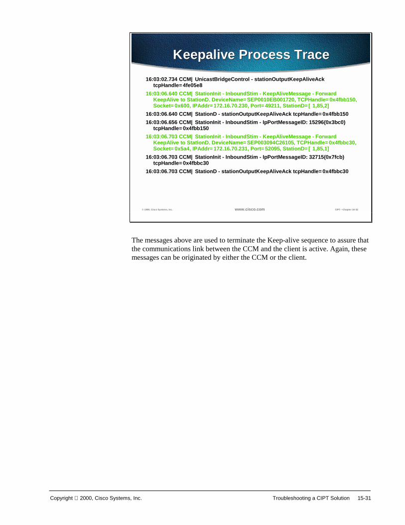
Copyright 2000, Cisco Systems, Inc. Troubleshooting a CIPT Solution 15-31
© 1999, Cisco Systems, Inc. www.cisco.com CIPT—Chapter 16-32
Keepalive Process TraceKeepalive Process Trace16:03:02.734 CCM|UnicastBridgeControl - stationOutputKeepAliveAck
tcpHandle=4fe05e816:03:06.640 CCM|StationInit - InboundStim - KeepAliveMessage - Forward
KeepAlive to StationD. DeviceName=SEP0010EB001720, TCPHandle=0x4fbb150, Socket=0x600, IPAddr=172.16.70.230, Port=49211, StationD=[1,85,2]
16:03:06.640 CCM|StationD - stationOutputKeepAliveAck tcpHandle=0x4fbb15016:03:06.656 CCM|StationInit - InboundStim - IpPortMessageID: 15296(0x3bc0)
tcpHandle=0x4fbb15016:03:06.703 CCM|StationInit - InboundStim - KeepAliveMessage - Forward
KeepAlive to StationD. DeviceName=SEP003094C26105, TCPHandle=0x4fbbc30, Socket=0x5a4, IPAddr=172.16.70.231, Port=52095, StationD=[1,85,1]
16:03:06.703 CCM|StationInit - InboundStim - IpPortMessageID: 32715(0x7fcb) tcpHandle=0x4fbbc30
16:03:06.703 CCM|StationD - stationOutputKeepAliveAck tcpHandle=0x4fbbc30
The messages above are used to terminate the Keep-alive sequence to assure thatthe communications link between the CCM and the client is active. Again, thesemessages can be originated by either the CCM or the client.

15-32 Cisco IP Telephony Copyright 2000, Cisco Systems, Inc.
Intra Cluster Call Flow Traces Through Cisco CallManager Trace UtilityThis section discusses the Intra Cluster call flow traces through a CiscoCallManager Trace utility.
© 1999, Cisco Systems, Inc. www.cisco.com CIPT—Chapter 16-33
Intra Cluster Call Flow TraceIntra Cluster Call Flow Trace16:05:41.625 CCM|StationInit - InboundStim - OffHookMessageID tcpHandle=0x4fbbc3016:05:41.625 CCM|StationD - stationOutputDisplayText tcpHandle=0x4fbbc30, Display=
1001 16:05:41.625 CCM|StationD - stationOutputSetLamp stim: 9=Line instance=1
lampMode=LampOn tcpHandle=0x4fbbc3016:05:41.625 CCM|StationD - stationOutputCallState tcpHandle=0x4fbbc3016:05:41.625 CCM|StationD - stationOutputDisplayPromptStatus tcpHandle=0x4fbbc3016:05:41.625 CCM|StationD - stationOutputSelectSoftKeys tcpHandle=0x4fbbc3016:05:41.625 CCM|StationD - stationOutputActivateCallPlane tcpHandle=0x4fbbc3016:05:41.625 CCM|Digit analysis: match(fqcn="", cn="1001", pss="", dd="")16:05:41.625 CCM|Digit analysis: potentialMatches=PotentialMatchesExist16:05:41.625 CCM|StationD - stationOutputStartTone: 33=InsideDialTone
tcpHandle=0x4fbbc3016:05:42.890 CCM|StationInit - InboundStim - KeypadButtonMessageID kpButton: 1
tcpHandle=0x4fbbc3016:05:42.890 CCM|StationD - stationOutputStopTone tcpHandle=0x4fbbc3016:05:42.890 CCM|StationD - stationOutputSelectSoftKeys tcpHandle=0x4fbbc3016:05:42.890 CCM|Digit analysis: match(fqcn="", cn="1001", pss="", dd="1")
In this call flow, an IP phone (dn=1001, tcpHandle= 0x4fbbc30, IPaddress=172.16.70.231) which is located in the cluster 2 is calling another IPPhone (dn=1000, tcpHandle= 0x4fbb150, IP address= 172.16.70.230) locatedwithin the same cluster.
Always remember that you can follow a trace for any device by looking at theTCP handle value, time stamp or name of the device. Also, remember that aunique TCP handle value get assigned to a device when it gets rebooted or itcomes on-line the first time. This TCP handle values stays the same for thisparticular device until it gets rebooted again and goes off line.
The traces above show that the IP phone (1001) has gone off hook. Observe theunique messages, TCP handle value and the called number, which are displayedon the IP phone. There is no calling number at this point, as the user has not triedto dial any digits.
Again, remember all of these are skinny messages between IP phones and CCM.
The trace above shows skinny messages going from CCM to IP phone. The firstmessage is turning the on the lamp on the calling party IP phone.
The stationOutputCallState message is used by CCM to notify the station ofcertain call related information.
The stationOutputDisplayPromptStatus message is used by CCM to cause a callrelated prompt message to be displayed on the station display.

Copyright 2000, Cisco Systems, Inc. Troubleshooting a CIPT Solution 15-33
The stationOutputSelectSoftKey message is used by the CCM to cause theskinny station to select a specific set of soft keys.
This message is used by CCM to instruct the skinny station as to the correct linecontext for the display.
In the message above the digit analysis process is ready to identify incomingdigit and match them for potential matches which exist for routing in thedatabase. The cn=1001 is the calling party number and dd="" is the dialed digit,which would show the called part number.
The debug above shows that the CCM is providing the inside dial tone to thecalling party IP phone.

15-34 Cisco IP Telephony Copyright 2000, Cisco Systems, Inc.
© 1999, Cisco Systems, Inc. www.cisco.com CIPT—Chapter 16-33
Intra Cluster Call Flow TraceIntra Cluster Call Flow Trace
16:05:42.890 CCM|Digit analysis: potentialMatches=PotentialMatchesExist16:05:43.203 CCM|StationInit - InboundStim - KeypadButtonMessageID kpButton: 0
tcpHandle=0x4fbbc3016:05:43.203 CCM|Digit analysis: match(fqcn="", cn="1001", pss="", dd="10")16:05:43.203 CCM|Digit analysis: potentialMatches=PotentialMatchesExist16:05:43.406 CCM|StationInit - InboundStim - KeypadButtonMessageID kpButton: 0
tcpHandle=0x4fbbc3016:05:43.406 CCM|Digit analysis: match(fqcn="", cn="1001", pss="", dd="100")16:05:43.406 CCM|Digit analysis: potentialMatches=PotentialMatchesExist16:05:43.562 CCM|StationInit - InboundStim - KeypadButtonMessageID kpButton: 0
tcpHandle=0x4fbbc3016:05:43.562 CCM|Digit analysis: match(fqcn="", cn="1001", pss="", dd="1000")16:05:43.562 CCM|Digit analysis: analysis results16:05:43.562 CCM||PretransformCallingPartyNumber=1001|CallingPartyNumber=1001|DialingPattern=1000|DialingRoutePatternRegularExpression=(1000)
Once CCM detects an incoming message and recognizes that the keypad button1 is pressed on the IP phone, it immediately stops the output tone. The messagesidentifying incoming keypad press sequences, i.e. digits 1000. Other messagesindicate the CCM is running the digit analysis process to match these digits.

Copyright 2000, Cisco Systems, Inc. Troubleshooting a CIPT Solution 15-35
© 1999, Cisco Systems, Inc. www.cisco.com CIPT—Chapter 16-34
Intra Cluster Call Flow TraceIntra Cluster Call Flow Trace|DialingRoutePatternRegularExpression=(1000)|DialingSdlProcessId=(1,38,2)|PretransformDigitString=1000|PretransformPositionalMatchList=1000|CollectedDigits=1000|PositionalMatchList=1000|RouteBlockFlag=RouteThisPattern16:05:43.562 CCM|Locations:Orig=0 BW=-1 Dest=0 BW=- (-1 implies infinite bw
available)16:05:43.578 CCM|StationD - stationOutputCallState tcpHandle=0x4fbb15016:05:43.578 CCM|StationD - stationOutputCallInfo CallingPartyName=1001,
CallingParty=1001, CalledPartyName=1000, CalledParty=1000, tcpHandle=0x4fbb15016:05:43.578 CCM|StationD - stationOutputSetLamp stim: 9=Line instance=1
lampMode=LampBlink tcpHandle=0x4fbb15016:05:43.578 CCM|StationD - stationOutputSetRinger: 2=InsideRing
tcpHandle=0x4fbb15016:05:43.578 CCM|StationD - stationOutputDisplayNotify tcpHandle=0x4fbb15016:05:43.578 CCM|StationD - stationOutputDisplayPromptStatus tcpHandle=0x4fbb15016:05:43.578 CCM|StationD - stationOutputSelectSoftKeys tcpHandle=0x4fbb150
Once the CCM has received enough digits to match, it will provide the digitanalysis results in a table format. Any extra digits typed on the phone at thispoint will be ignored by the CCM, as a match has already been found.
The above traces show that the CCM is now sending out this information to acalled party phone, which is evident from tcpHandle number.
The above traces shows us that now the CCM commands the called part IPphone’s lamp to blink for incoming call indication.
The CCM is provides ringer, display notification, and other call relatedinformation to called party IP phone. Again, keep this information by followingtcpHandle number.
The figure above represents the CCM begins providing an alerting or ringingtone to the calling party’s IP phone, notifying that the connection has beenestablished.

15-36 Cisco IP Telephony Copyright 2000, Cisco Systems, Inc.
© 2000, Cisco Systems, Inc. www.cisco.com CIPT v2.0—16-33
Intra Cluster Call Flow TraceIntra Cluster Call Flow Trace
16:05:43.578 CCM|StationD - stationOutputCallState tcpHandle=0x4fbbc3016:05:43.578 CCM|StationD - stationOutputCallInfo CallingPartyName=1001,CallingParty=1001, CalledPartyName=, CalledParty=1000, tcpHandle=0x4fbbc3016:05:43.578 CCM|StationD - stationOutputCallInfo CallingPartyName=1001,
CallingParty=1001, CalledPartyName=1000, CalledParty=1000, tcpHandle=0x4fbbc3016:05:43.578 CCM|StationD - stationOutputStartTone: 36=AlertingTone
tcpHandle=0x4fbbc3016:05:43.578 CCM|StationD - stationOutputCallState tcpHandle=0x4fbbc3016:05:43.578 CCM|StationD - stationOutputSelectSoftKeys tcpHandle=0x4fbbc3016:05:43.578 CCM|StationD - stationOutputDisplayPromptStatus tcpHandle=0x4fbbc3016:05:45.140 CCM|StationD - stationOutputStopTone tcpHandle=0x4fbbc3016:05:45.140 CCM|StationD - stationOutputOpenReceiveChannel tcpHandle=0x4fbbc30
myIP: e74610ac (172.16.70.231)16:05:45.140 CCM|StationD - ConferenceID: 0 msecPacketSize: 20
compressionType:(4)Media_Payload_G711Ulaw64k16:05:45.140 CCM|StationD - stationOutputStopTone tcpHandle=0x4fbb15016:05:45.140 CCM|StationD - stationOutputOpenReceiveChannel tcpHandle=0x4fbb150
myIP: e64610ac (172.16.70.230)
At this point, the called party’s IP phone goes off hook. Therefore, CCM stopsgenerating the ringer tone to calling party. The message above is used by theCCM to cause the Skinny Client to begin receiving a unicast RTP stream. Thiscan be observed in the following traces that CCM provides the IP address ofcalled party as well as codec information, and packet size in msec(millisecondsPacketSize is an integer containing the sampling time inmilliseconds used to create the RTP packets. NOTE: normally this value is set to30msec.) In our case it is set to 20msec, which is obvious from the redhighlighted trace message.
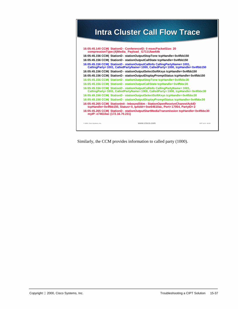
Copyright 2000, Cisco Systems, Inc. Troubleshooting a CIPT Solution 15-37
© 2000, Cisco Systems, Inc. www.cisco.com CIPT v2.0—16-34
Intra Cluster Call Flow TraceIntra Cluster Call Flow Trace
16:05:45.140 CCM|StationD - ConferenceID: 0 msecPacketSize: 20 compressionType:(4)Media_Payload_G711Ulaw64k
16:05:45.156 CCM|StationD - stationOutputStopTone tcpHandle=0x4fbb15016:05:45.156 CCM|StationD - stationOutputCallState tcpHandle=0x4fbb15016:05:45.156 CCM|StationD - stationOutputCallInfo CallingPartyName=1001,
CallingParty=1001, CalledPartyName=1000, CalledParty=1000, tcpHandle=0x4fbb15016:05:45.156 CCM|StationD - stationOutputSelectSoftKeys tcpHandle=0x4fbb15016:05:45.156 CCM|StationD - stationOutputDisplayPromptStatus tcpHandle=0x4fbb15016:05:45.156 CCM|StationD - stationOutputStopTone tcpHandle=0x4fbbc3016:05:45.156 CCM|StationD - stationOutputCallState tcpHandle=0x4fbbc3016:05:45.156 CCM|StationD - stationOutputCallInfo CallingPartyName=1001,
CallingParty=1001, CalledPartyName=1000, CalledParty=1000, tcpHandle=0x4fbbc3016:05:45.156 CCM|StationD - stationOutputSelectSoftKeys tcpHandle=0x4fbbc3016:05:45.156 CCM|StationD - stationOutputDisplayPromptStatus tcpHandle=0x4fbbc3016:05:45.265 CCM|StationInit - InboundStim - StationOpenReceiveChannelAckID
tcpHandle=0x4fbb150, Status=0, IpAddr=0xe64610ac, Port=17054, PartyID=216:05:45.265 CCM|StationD - stationOutputStartMediaTransmission tcpHandle=0x4fbbc30
myIP: e74610ac (172.16.70.231)
Similarly, the CCM provides information to called party (1000).
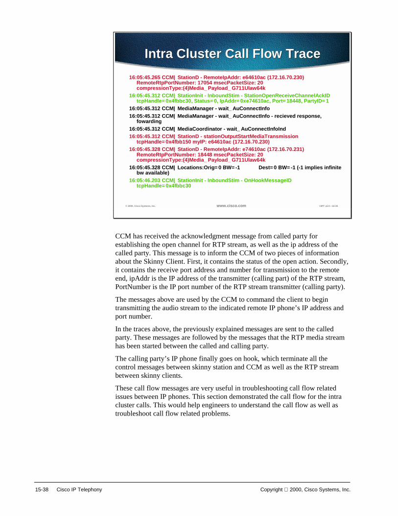
15-38 Cisco IP Telephony Copyright 2000, Cisco Systems, Inc.
© 2000, Cisco Systems, Inc. www.cisco.com CIPT v2.0—16-35
Intra Cluster Call Flow TraceIntra Cluster Call Flow Trace16:05:45.265 CCM|StationD - RemoteIpAddr: e64610ac (172.16.70.230)
RemoteRtpPortNumber: 17054 msecPacketSize: 20 compressionType:(4)Media_Payload_G711Ulaw64k
16:05:45.312 CCM|StationInit - InboundStim - StationOpenReceiveChannelAckID tcpHandle=0x4fbbc30, Status=0, IpAddr=0xe74610ac, Port=18448, PartyID=1
16:05:45.312 CCM|MediaManager - wait_AuConnectInfo16:05:45.312 CCM|MediaManager - wait_AuConnectInfo - recieved response,
fowarding16:05:45.312 CCM|MediaCoordinator - wait_AuConnectInfoInd16:05:45.312 CCM|StationD - stationOutputStartMediaTransmission
tcpHandle=0x4fbb150 myIP: e64610ac (172.16.70.230)16:05:45.328 CCM|StationD - RemoteIpAddr: e74610ac (172.16.70.231)
RemoteRtpPortNumber: 18448 msecPacketSize: 20 compressionType:(4)Media_Payload_G711Ulaw64k
16:05:45.328 CCM|Locations:Orig=0 BW=-1 Dest=0 BW=-1 (-1 implies infinite bw available)
16:05:46.203 CCM|StationInit - InboundStim - OnHookMessageID tcpHandle=0x4fbbc30
CCM has received the acknowledgment message from called party forestablishing the open channel for RTP stream, as well as the ip address of thecalled party. This message is to inform the CCM of two pieces of informationabout the Skinny Client. First, it contains the status of the open action. Secondly,it contains the receive port address and number for transmission to the remoteend, ipAddr is the IP address of the transmitter (calling part) of the RTP stream,PortNumber is the IP port number of the RTP stream transmitter (calling party).
The messages above are used by the CCM to command the client to begintransmitting the audio stream to the indicated remote IP phone’s IP address andport number.
In the traces above, the previously explained messages are sent to the calledparty. These messages are followed by the messages that the RTP media streamhas been started between the called and calling party.
The calling party’s IP phone finally goes on hook, which terminate all thecontrol messages between skinny station and CCM as well as the RTP streambetween skinny clients.
These call flow messages are very useful in troubleshooting call flow relatedissues between IP phones. This section demonstrated the call flow for the intracluster calls. This would help engineers to understand the call flow as well astroubleshoot call flow related problems.

Copyright 2000, Cisco Systems, Inc. Troubleshooting a CIPT Solution 15-39
Summary
© 1999, Cisco Systems, Inc. www.cisco.com CIPT—Chapter 16-23
SummarySummary
• The tools available to troubleshoot potential problems are on the Cisco CallManager Server.
• Understanding the call flow and debug traces will make it easier to isolate a problem and determine which component is causing the problem
The main goal of this troubleshooting chapter is to explain the tools available totroubleshoot potential problems and to understand the call flows and series ofevents through the call traces and debug outputs. The tools and utilities that areavailable are the following:
■ Cisco CallManager Administration
■ Performance Monitor
■ Event Log
■ Local Log Files
■ SDL Trace
■ Trace Utility
Once you understand the call flow and debug traces, it will be easier to isolate aproblem and determine which component is causing the problem. Understandingthe information provided in this chapter will help to find a resolution quicker, aswell as to isolate most of their issues.

15-40 Cisco IP Telephony Copyright 2000, Cisco Systems, Inc.

Copyright 2000, Cisco Systems, Inc. Troubleshooting a CIPT Solution 15-41
Review Questions
© 1999, Cisco Systems, Inc. www.cisco.com CIPT—Chapter 16-24
Review QuestionsReview Questions
• Which tool provides the system version, administration version and database information about the Cisco CallManager?
• In order to monitor a variety of system variables in real time, which tool would need to be used?
• What are the three categories Event viewer has?
Q1) Of the tools on the Cisco CallManager server, which tool will provide the systemversion number, administration version number and database information aboutthe Cisco CallManager server?
Q2) Monitoring a variety of system variables in real time can be useful, which tool isable to provide such monitoring capabilities?
Q3) The Event viewer creates Event Logs, what are the three categories the Eventviewer can log?

15-42 Cisco IP Telephony Copyright 2000, Cisco Systems, Inc.

Copyright 2000, Cisco Systems, Inc. Troubleshooting a CIPT Solution 15-43
Laboratory Exercises

15-44 Cisco IP Telephony Copyright 2000, Cisco Systems, Inc.