
Overview and Commercial Examples - Koç...
57
Reconfigurable Architectures Overview and Commercial Examples Doug Densmore [email protected] EE249 10/16/03
Transcript of Overview and Commercial Examples - Koç...
�
Reconfigurable ArchitecturesOverview and Commercial Examples
Doug [email protected]
EE249
10/16/03

�Outline
� Introduction to Reconfigurable Architectures
� Motivation for Reconfigurable Architectures
� Reconfigurable Architecture Classifications
� Reconfigurable Architecture Challenges
� Commercial Examples
� Cypress Semiconductors’ PSoC
� Xilinx’s Virtex II Pro
� Conclusion

�
Introduction
� What is a reconfigurable architecture?
� Depends on who you ask and how you would like to classify your architecture (to come later).
� Static vs. Configurable vs. Reconfigurable?
� What is an architecture?
� Depends again on who you talk to!!
� Modeling perspective vs. programming perspective vs. design perspective?

�Introduction
� For our purposes I will propose the most generic:
� Reconfigurable Architecture – device which provides processing and communication services which can redefine their relationship via user input at some point in either the design or execution aspects of its usage.
� Still questions: System vs. Architecture?

�
Motivation
� Why develop a reconfigurable architecture?
� IC trends: Migration from ASIC to platforms to programmable platforms
� Who uses a reconfigurable architectures?
� This determines what features are relevant
� ISA, Control, Computation, Abstraction, Programming interface
� This determines at what point the device should be configurable
� At plant
� During application
� Middle Ground?

�
Motivation - System Design in 200x
� Less like synthesis of an integrated circuit from a high-level description
� More like programming of a complex application-specific processor
RTLSynthesis
HDL
netlist
logicoptimization
netlist
Library
physicaldesign
layout
IMPACTFront-End
Simulator / Visualization
ELCORBack-End
MESCALELCORMDES
MESCALMDES
C
Courtesy K.Keutzer

�
Motivation -Evolution of the EDA Industry
Effort
(EDA tools effort)
Results
(Design Productivity)
a
b
s
q0
1
d
clk
1978197819781978
1985198519851985
1992199219921992
1999199919991999
Transistor entry - Calma, Computervision
Schematic Entry - Daisy, Mentor, Valid
Synthesis - Cadence, Synopsys
ASIP/Prog Platform
McKinsey S-Curve
Courtesy K.Keutzer
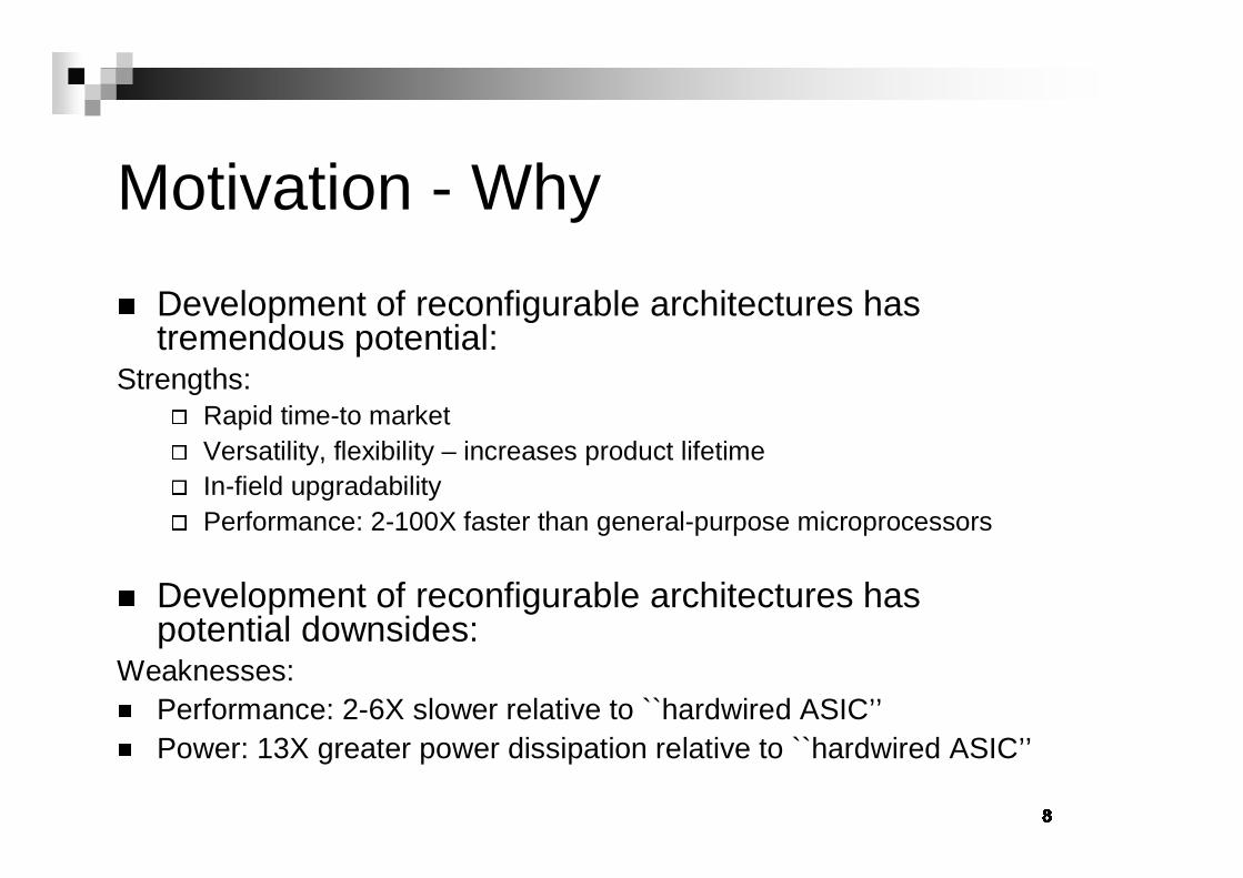
�Motivation - Why
� Development of reconfigurable architectures has tremendous potential:
Strengths:
� Rapid time-to market
� Versatility, flexibility – increases product lifetime
� In-field upgradability
� Performance: 2-100X faster than general-purpose microprocessors
� Development of reconfigurable architectures has potential downsides:
Weaknesses:
� Performance: 2-6X slower relative to ``hardwired ASIC’’
� Power: 13X greater power dissipation relative to ``hardwired ASIC’’

�Motivation - Who
� Reconfigurable Architectures naturally appeal to different groups of people:
� Academic
� Industrial
� Military
� Looking to take advantage of the particular strengths for their application space
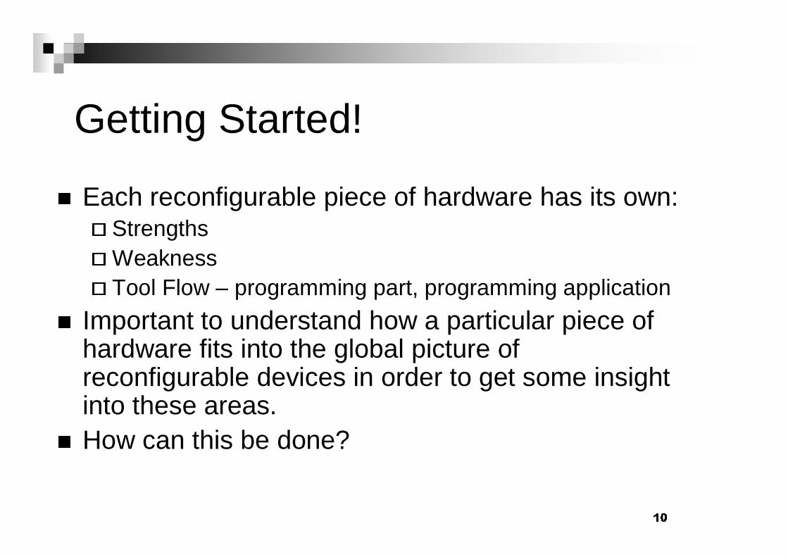
� �Getting Started!
� Each reconfigurable piece of hardware has its own:
� Strengths
� Weakness
� Tool Flow – programming part, programming application
� Important to understand how a particular piece of hardware fits into the global picture of reconfigurable devices in order to get some insight into these areas.
� How can this be done?

� �Characteristics of Reconfigurable Architectures
� There is no “one” reconfigurable architecture or “one” reconfiguration characteristic.
�
Reconfiguration manifests itself particular areas reflecting possible applications.
The required resources for computation are distributed throughout the device.
Distributed Resources
Units process data based on local control.Distributed Control
Functionality and the interconnection network of the computational units is flexible.
Configurable Datapath
Data processed by spatially distributing the computations.
Spatial Computation
DescriptionCharacteristic
Bondalapati and Prasanna - USC

��
Characteristics of Reconfigurable Architectures
ReconfigurableReconfigurableLogicLogic
ReconfigurableReconfigurableDatapathsDatapaths
adder
buffer
reg0
reg1
muxCLB CLB
CLBCLB
DataMemory
InstructionDecoder
&Controller
DataMemory
ProgramMemory
Datapath
MAC
In
AddrGen
Memory
AddrGen
Memory
ReconfigurableReconfigurableArithmeticArithmetic
ReconfigurableReconfigurableControlControl
Bit-Level Operationse.g. encoding
Dedicated data pathse.g. Filters, AGU
Arithmetic kernelse.g. Convolution
RTOSProcess management
Courtesy K.Keutzer

� �Classification of Reconfigurable Architectures
� Technology
�
A coarse classification can be made based upon the technology used to make the device.
�
This provides some insight into
� Programming, Organization
Mix of discreet and continuous type components
Hybrid Architectures
Contains both static and reconfigurable components.
System on Chip (SOC)
Contaminates uncommitted configurable analog blocks (CABs)
Field Programmable Analog Array (FPAA)
Contains uncommitted configurable logic blocks (CLBs)
Field Programmable Gate Array (FPGA)
PROMs, PLAsProgrammable Logic Device
DescriptionDevice

��
Classification of Reconfigurable Architectures
� Properties
� Technology does not really address the “programming model” for the device.
� What is available to the designer?
� Four properties introduced by Bondalapati and Prasanna at USC
� Granularity
� Host Coupling
� Reconfiguration Methodology
� Memory Organization

��
Classification of Reconfigurable Architectures
How computations access memory.
Example: Large blocks, distributed
Memory Organization
How the device is programmed.
Examples: bitstream (serial, parallel), dynamic, partial
Reconfiguration Methodology
Type of coupling to host processor
Loose System Level/Loose Chip Level/Tight Chip Level.
Examples: Through IO (SPLASH), Direct Communication (PRISM), same chip (GARP, Chameleon)
Host Coupling
Size of the smallest reconfigurable functional unit addressed by mapping tools. Tradeoff between flexibility and performance overhead.
Examples: CLB, ADC, ISA
Granularity
DescriptionClassification

� �
Classification of Reconfigurable Architectures
� An alternate approach by P.Schaumont et al. is based on three orthogonal axes.
� Vertical
� Level of abstraction
� Horizontal
� Reconfigurable feature density
� Time
� Timing relationship of configuration processing

� �
Classification of Reconfigurable Architectures - Vertical Axis
� This represents the level of abstraction.
� Four basic descriptions
� Implementation (I)– indicates that the physical implementation can change. Example: power vs. performance.
� Microarchitecture (M) – Function unit organization can change.
� ISA – programmer’s view change from an instruction set standpoint.
� Process/Systems Architecture (P) – Buffer sizes, task organization

� �
Classification of Reconfigurable Architectures - Vertical Axis
www.acca.beISAC-RISP, KULeuven
www.cs.ucla.edu/elib/reconfigurable
I, MSPS, UCLA
www.eng.uci.edu/morphosysI, ISA, PMorphoSys, UCI
www.ece.cum.edu/research/piperench
MPipeRench, CMU
Brass.cs.berkeley.eduI, ISA, PGARP, UCB
Academic
www.cypressmicro.comI, MPSoC, Cypress
www.chameleonsystems.comM, PCS2112, Chameleon Sys.
www.atmel.comI, PFPSLIC, ATMEL
www.trisend.comISA, PE7/A5, Trisend
www.morphics.comPMorphics
www.pmc-sierra.comPMECA41, PMC-Sierra
www.altera.comI,MExcalibur, Altera
Commercial
ReferenceVertical AxisPlatform

� �
Classification of Reconfigurable Architectures - Horizontal Axes
� This represents feature diversity
� Typically features are in communication, storage, and processing.
� Interaction across horizontal and vertical axes.
Number/Type Tasks
Buffer SizeIntercon. NetworkProcess Architecture
Custom Instr.Reg. SetAddress SizeISA
Execution Unit Type
Reg file size, Cache
Crossbar/BusMicorarchitecture
CLB/IP BlockRAM orgSwitches,.MuxesImplementation
ProcessingStorageCommunication
(Horizontal Axis)
Design Elements
Design Levels

��
Classification of Reconfigurable Architectures - Time Axis
� Timing relationship of configuration processing
� Based on binding time
� When the configuration data is sent to the part
� Implementation vs. design time binding
� Implementation – postponed until actual execution of the part.
� Design Time - when the part is conceived.
� Typically the lower level features are bound at design time while others are at implementation time. In between there is the binding time continuum.

��
Classification of Reconfigurable Architectures
FPGA Processor
SpecializedMicro-Architectures
SpecializedInstruction-SetArchitectures
Domain-Specialization
ChameleonSystems
Morphics
Frontier Design
TensilicaARC
Improv Systems
PMC Sierra
Xilinx Altera AtmelTriscend
ActelAdaptive Silicon
Proceler
Network Processors
Courtesy K.Keutzer
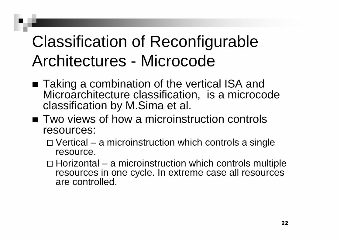
� �Classification of Reconfigurable Architectures - Microcode
� Taking a combination of the vertical ISA and Microarchitecture classification, is a microcode classification by M.Sima et al.
� Two views of how a microinstruction controls resources:
� Vertical – a microinstruction which controls a single resource.
� Horizontal – a microinstruction which controls multiple resources in one cycle. In extreme case all resources are controlled.

� �
Classification of Reconfigurable Architectures - Microcode

� �Classification of Reconfigurable Architectures - SET instruction
� In addition to the microcode distinction, there is the notion of a SET instruction.
� This instruction initiates the reconfiguration of raw hardware.
� Can be used in conjunction which the microcode classification.
� This is the extremes of the time axis mentioned in the previous classification method.

��
Classification of Reconfigurable Architectures – SET and µcode
Xputer/rALU
CCSimP
Gilson’s CCM
Nano-Processor
URISC
rDPAChimaeraOneChip-98
ColtMultiple-RISAGARP
RaPiDDISCMIPS + REMARC
VEGAOneChip-98’RISA’’
RISA’’ConCISe 7RISA
Alippi’s VLIWOneChipPRISMII/RASC
PipeRenchCoMPAREPRISCPRISM
w/o SETExplicit SETw/o SETExplicit SET
Horizontal
�codeVertical �code

��
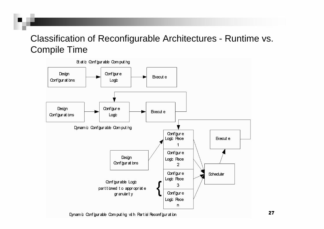
Classification of Reconfigurable Architectures - Runtime vs. Compile Time
� Related to the Time Axis as well as the SET instruction.
�
Time Axis allows for a less coarse continuum.
�
SET is the opposite extreme.
� Often referred to as dynamic vs. static reconfigurability
� Compile Time – predetermined configuration which remains until the completion of a particular task.
� Runtime – can repeated program a device with many smaller functions to complete a particular application.
�
Overhead associated with this reconfiguration
�
Key performance issues: configuration time reduction and retention of intermediate values.
��
Classification of Reconfigurable Architectures - Runtime vs. Compile Time

��Reconfigurable Challenges
� Notice the similarities as well as differences in the previously mentioned methods of classification.
�
Similarities point out some fundamental issues with reconfigurable devices
� Abstraction Levels, Binding Times
�
Differences point out features which may be more a function of the device then the architectures in general.
� Key Challenge is how to cope with
�
Static vs. Dynamic Reconfiguration
�
Design Methodologies
�
Multi-dimensional Optimization
�
Design Tools

��
Reconfigurable Challenges – Static vs. Dynamic
� This requires that scheduling configurations and constraints are accounted for so that applications can take advantage of a hardware which can adapt continuously.
� “Design Methodologies for Partially Reconfigured Systems” – Hadley and Hutchings – Brigham Young
� Looks at how to optimally reconfigure only aspects of the device which require a change thus saving configuration time.

��
Reconfigurable Challenges –Design Methodologies
� Platform Based Design
�
Constraints, Applications, Platforms, Estimation (CAPE) –Densmore, ASV - UCB
� Boolean Constraint Based with PBD
� Hybrid System Architecture Model (HySAM) –Bondalapati - USC
�
Von-Neuman style processor and configurable logic unit.
� Finds “optimal” partitions of the capabilities of the hardware from the implementations.
� SCORE – Wawrzynek, et al – UCB
�
Virtualizes computing resources by dividing computation into fixed size “pages” and time multiplexing the pages on available physical hardware.

��
Reconfigurable Challenges –Multidimensional Optimization
� Design space exploration process in which multiple metrics are examined.
� Three Axes
� Application Constraints
� Architecture Constraints
� Adaptation Constraints
� For example: Configuration overhead vs. performance (adaptation vs. architecture with a requirement to meet application needs)

��
Reconfigurable Challenges –Design Tools
� Architecture Based
�
Propose ways of organizing and interfacing configurable logic.
� Theoretical Modeling
�
Reconfigurable Mesh analysis, Virtual Hardware Operating Systems
� Algorithmic Synthesis
�
Techniques to schedule computations on dynamically reconfigurable machines.
� Software Tools
�
Mapping Techniques, run-time reconfiguration, compilation from high level languages, simulation, operating systems, etc

� �
Reconfigurable Challenges –Design ToolsTools that help build thecomplex programmablechips
ProgramROM
A/DD/A
P=>SS=>P
CoreµP
ASICCircuitry
DMA
Tools that help program them
On-chipprogram
RAM
FPGA
Off-chipRAM
signal integrity
3D-extraction
SW estimators
performancevisualization
runtimescheduling
debugger
gridless router
RTLmodel
RTLfloorplanner
logic synthesis
compiler
Courtesy K.Keutzer

��Cypress Semiconductors’ PSoC
� Developed by Cypress Microsystems, a subsidiary of Cypress Semiconductor. Acquired March 6th, 2000.
� PSoC Released November 13, 2000
�
“As general purpose solutions, PSoC devices are targeted for implementation in embedded applications, including audio, wireless, handheld, data communications, Internet control, industrial, and consumer systems. “
� Named Innovation of the Year 2001 by EDN Magazine.
� Berkeley provided with a PSoC development kit as member of GSRC.
http://www.cypressmicro.com

��
Cypress Semiconductors’ PSoC-Hardware Overview
� Harvard Architecture Processor
�
M8C; Up to 24MHz; Flexible Addressing modes
�
Separate MAC; 8x8 multiply, 32 bit accumulate
� On Chip Memory
�
Flash 4k to 16k - SONOS™-based (Silicon Oxide Nitride Oxide Silicon)
�
256 Bytes SRAM
�
EEPROM Emulation in Flash
� Programmable System on a Chip Blocks
�
12 Analog Blocks
�
8 Digital Blocks

��
Cypress Semiconductors’ PSoC-Application Overview
� Company Line*
�
“PSoC™ Devices Integrate Programmable Analog and Digital Functions To Simplify Design Of Wireless, Handheld, Data Communications, and Industrial Systems”
� Sample Application Notes
�
Range Finder
�
1-GHz Vectorial Network Analyzer
�
Remote Human Health Monitoring System
� Dynamic reconfiguration is a key application point.

��
Cypress PSoCSystem Overview
�Keys to note:
� Programmable interconnect
� Digital PSoC Blocks
� Analog PSoC Blocks
� Separate MAC
� Static Peripherals
� LVD, Decimator, etc
�Exposed to Programmer through “Module Placement view”
�Exposed to Programmer through “Application View”
http://www.cypressmicro.com

��PSoC - M8C
� 8-bit, Harvard Architecture Microprocessor
� Five Hardware Registers
� Flags (F) – 3 Status Bits, Global Interrupt Bit, XIO (regbank switch)
� Program Counter (PC)– 16 bit; Full addressing of the 16K FLASH
� Accumulator (A)
� Stack Pointer (SP)
� Index (X) – Used in addressing Modes; Often used by peripherals
CPU ProgramMem
DataMem
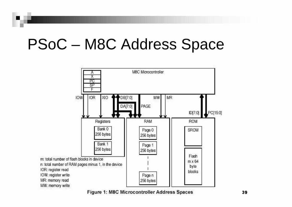
��PSoC – M8C Address Space

��
Cypress Semiconductors’ PSoC-Digital Blocks
� Total of 8, 8-bit digital blocks
�
Four Digital Basic Type A (DBA) and four Digital Communications Type A (DCA)
�
Each can be configured independently or in combination
�
Each have a unique Interrupt Vector and Interrupt Enable bit
� Three Configuration Registers to program
�
Function Register – function and mode
� Timer, Counter, CRC/PRS, Deadband (for PWM), UART, Serial Peripheral Interface (SPI)
�
Input Register – data input and clock selection
�
Output Register – select and enable outputs

��
Cypress Semiconductors’ PSoC-Digital Blocks
� Three Data Registers
� Data0, Data1, Data2 – function dependent
� One Control Register� Sample Register
� Exposed in the “Module Placement View “

��
Cypress Semiconductors’ PSoC-Digital Blocks

� �Cypress Semiconductors’ PSoC-Analog Blocks
� 12 analog blocks
� 4 Continuous Time Blocks, 4 Type A Switched Capacitor, and 4 Type B Switched Capacitor
� Three Distinct outputs from each analog block
� The analog output bus (ABUS) shared by all blocks in analog column.
� The comparator bus (CBUS) which is a digital resource shared by all blocks in a column.
� The output bus (Out) which is shared by all blocks in the column and can be reconfigured to send a signal externally.

� �Cypress Semiconductors’ PSoC-Analog Blocks
� Analog Block Registers
� Analog Column Clock Select Register
� Analog Reference Control Register
� Analog Clock Select Register
� Control0, Control1, Control2 Registers (Control3 for SwCap Blks)
� Exposed in the “Module Placement View “

��
Cypress Semiconductors’ PSoC-Analog Blocks

��
Cypress Semiconductors’ PSoC-User Modules
� User modules are what the programmer really sees when configuring the device.
� Could be considered a primitive component along with the M8C and static peripherals.
� Current User Modules (sample in table).
� New modules in software updates.
115 Flash2D16-bit PWM
29 Flash2A SwCpTwo Pole Band Pass Filter
56 Flash2D16-bit CRC
47 Flash1A SwCp6-Bit DAC
66 Flash1D8-bit Counter
32 Flash1A CT Programmable Gain Amp
184 Flash6 SRAM
2D, 1A12-Bit ADC
Memory (Bytes)
PSoCBlocks

��
Cypress Semiconductors’ PSoC-Programming Environment
� Windows based graphical programming environment both for the configuration of the reconfigurable blocks and interconnect, as well as the development of the software.
� Multiple Editors (“Views”)
� Device Editor
� Application Editor
� Debugger

��
Cypress Semiconductors’ PSoC-Dynamic Reconfiguration
� In the Module Selection view, you can import (or export) configurations.
� Configurations consist of user modules, their interconnections, and their parameters.
� Then at runtime you can swap to another configuration via
�
call UnloadConfig_newled_proj
�
call LoadConfig_dynamic_improved
� This amounts to swapping out and reloading of the PSoCblock registers mentioned earlier.
�
Stores the configurations in FLASH
�
100+ cycles (best guess)
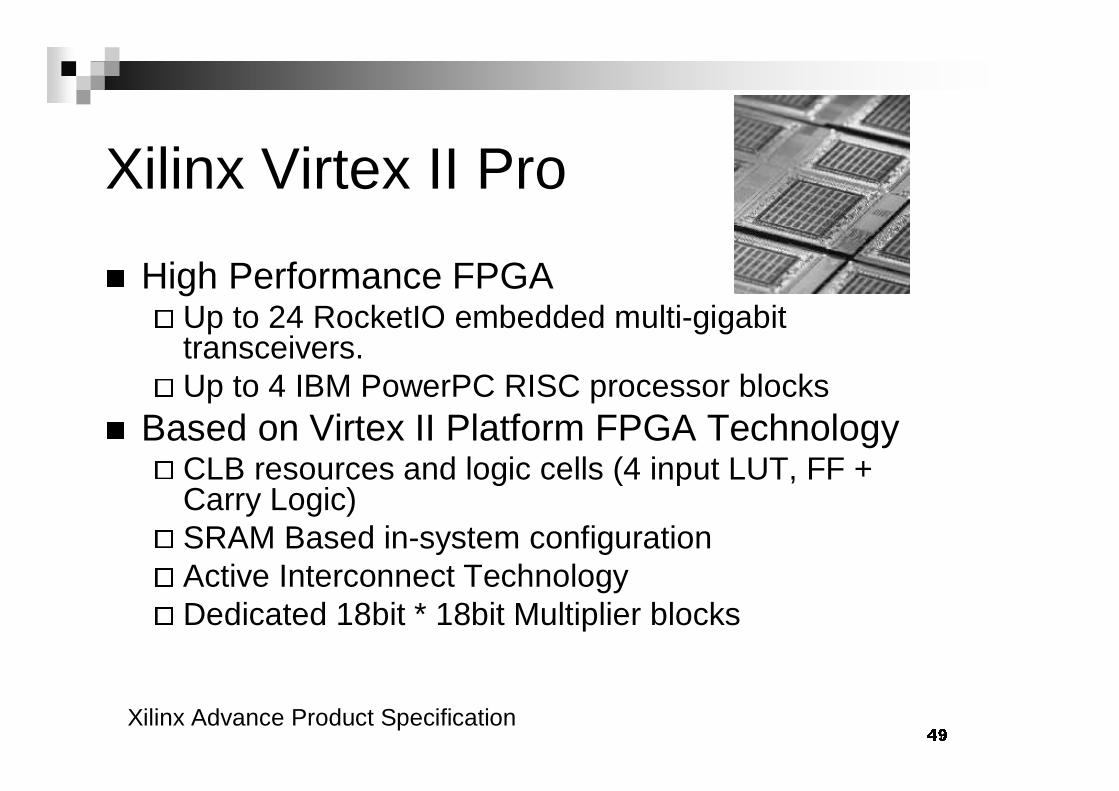
��Xilinx Virtex II Pro
� High Performance FPGA
� Up to 24 RocketIO embedded multi-gigabit transceivers.
� Up to 4 IBM PowerPC RISC processor blocks
� Based on Virtex II Platform FPGA Technology
� CLB resources and logic cells (4 input LUT, FF + Carry Logic)
� SRAM Based in-system configuration
� Active Interconnect Technology
� Dedicated 18bit * 18bit Multiplier blocks
Xilinx Advance Product Specification

� �
Virtex II Pro Generic Architecture Overview
� Embedded RocketIOMulti-Gigabit Transceiver (MGT)
� Processor block containing embedded IBM PowerPC
� FPGA Fabric

� �Xilinx Virtex II Power PC Core

� �Virtex II Tool Flow
� Main Package is Xilinx ISE tools
�
HDL Based Designs
�
Schematic Based Designs
�
Behavioral Simulation
� Modelsim Based
�
Design Implementation
�
Timing Simulation
� Synthesis
�
Xilinx Synthesis Technology (XST)
� Works for both HDL and Schematic Designs
� Part of ISE
�
Synplify/Synplify Pro
� Schematic based; Not part of ISE
�
LeonardoSpectrum
� Works for both HDL and Schematic Designs; Not part of ISE

� �Virtex II IP Blocks
� Key Tool is Xilinx’s Core Generator
� The Xilinx CORE Generator System generates and delivers parameterizable cores optimized for Xilinx FPGAs.
� Both Xilinx and 3rd party cores
� Communication/Network
� Math
� DSP
� Memories/Storage
� Microprocessors/Controllers
� Video/Audio Processing

� �
Virtex II Applications
� Networking - network switch fabrics� Wireless base-stations� Mass storage� Video servers - video-on-demand servers� Software-defined radio (SDR) with
Mercury Computer Systems
� �
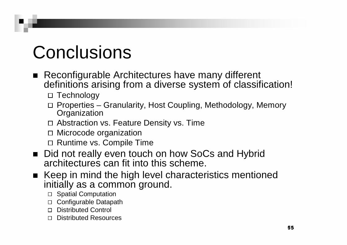
Conclusions
� Reconfigurable Architectures have many different definitions arising from a diverse system of classification!
�
Technology
�
Properties – Granularity, Host Coupling, Methodology, Memory Organization
�
Abstraction vs. Feature Density vs. Time
�
Microcode organization
�
Runtime vs. Compile Time
� Did not really even touch on how SoCs and Hybrid architectures can fit into this scheme.
� Keep in mind the high level characteristics mentioned initially as a common ground.
�
Spatial Computation
�
Configurable Datapath
�
Distributed Control
�
Distributed Resources

� �Conclusions
� The right choice of a reconfigurable device can greatly HELP or HURT your application.
� Because of the relative strengths and weaknesses of the various devices you should examine how your application will run on each device.
� Reconfigurable devices fit very nicely into many tool chains which seek to examine various architecture instances.
� Platform Based Design – Many different architecture instances.
��Conclusions
� Reconfigurable architectures are here to stay!
� Deal with increased time to market pressures
� Need to keep costs of products low (reuse, IP blocks, etc)
� One supplier can be vender of choice.
� Many great research problems can be investigated will relatively simple devices.
� Scheduling, mapping, hardware/software co-design, testing, etc