Overlap of multiple irrigations. 3-D Uniformity Simulation.
85
Overlap of multiple irrigations 0 10 20 30 40 50 0 1 2 3 4 5 distance along travel path application depth Pass 1 Pass 2 Pass 3 sum
-
Upload
vivien-collins -
Category
Documents
-
view
219 -
download
1
Transcript of Overlap of multiple irrigations. 3-D Uniformity Simulation.

Overlap of multiple irrigations
0 10 20 30 40 50
0
1
2
3
4
5
distance along travel path
appl
icat
ion
dept
h
Pass 1 Pass 2 Pass 3
sum

3-D Uniformity Simulation
3-D Uniformity Simulation

3-D Uniformity Simulation

3-D Uniformity Simulation

3-D Uniformity Simulation

3-D Uniformity Simulation

3-D Uniformity simulation

© Irrigation Association

Main causes of non-uniformity
• Nozzles installed in the wrong order
• Damaged or plugged sprinklers• Damaged sprinkler replaced with
whatever is in the truck

© Irrigation Association
Trash in the regulator

© Irrigation Association
Trash on/in the sprinkler

© Irrigation Association
Replaced by anything in the truck
Lower uniformity costs more
• pumping cost and • reduced yields

Controlling Runoff

FACTORS AFFECTING RUNOFF
1. SYSTEM CAPACITY - GALLONS/MINUTE PER ACRE
780 GPM / 130 ACRES = 6 GPM/ACRE
2. DEPTH OF APPLICATION PER REVOLUTION - INCHES
3. SPRINKLER PACKAGE - SPRAY, IMPACT, LEPA
4. SOIL SURFACE CONDITIONS -
AMOUNT OF WATER THE SOIL SURFACE WILL HOLD

POTENTIAL RUNOFF UNDER CENTER PIVOTS
0.0 0.2 0.4 0.6 0.8 1.0
4.0
3.5
3.0
2.5
2.0
1.5
1.0
0.5
0.0
PEAK APPLICATION RATE
TIME, hours
RA
TE
S,
inch
es /
hou
r
TIME OFWETTING

POTENTIAL RUNOFF UNDER CENTER PIVOTS
900 GPM130 ACRES
50 FT WETTED DIAMETER1 INCH APPLICATION
0.0 0.2 0.4 0.6 0.8 1.0
4.0
3.5
3.0
2.5
2.0
1.5
1.0
0.5
0.0
APPLICATION RATE
INFILTRATION RATE
TIME, hours
RA
TE
S,
inch
es /
hou
r

POTENTIAL RUNOFF UNDER CENTER PIVOTS
0.0 0.2 0.4 0.6 0.8 1.0
4.0
3.5
3.0
2.5
2.0
1.5
1.0
0.5
0.0
POTENTIAL RUNOFF
TIME, hours
RA
TE
S, i
nch
es
/ ho
ur
900 GPM130 ACRES
50 FT WETTED DIAMETER1 INCH APPLICATION
SURFACE STORAGE

SURFACE STORAGE
SOIL DEPRESSIONSSTORE WATER
LESS STORAGE ON STEEP SLOPES
SOIL

EFFECT OF SPRINKLER PACKAGES ON APPLICATION RATE
0.0 0.2 0.4 0.6 0.8 1.0 1.2 1.4
4.03.5
3.0
2.5
2.0
1.5
1.0
0.5
0.0
TIME, hours
AP
PLI
CA
TIO
N R
AT
E, i
nch/
hr 900 gpm1300 ft distance1 inch applic.130 acres
PACKAGES
40 ft - 360 Degree Sprays70 ft - Low Pressure120 ft - Medium Pressure160 ft - High Pressure

TIME OF APPLICATION, hours
CHANGE OF APPLICATION RATE ALONG A PIVOT
0 0.2 0.4 0.6 0.8 1.0
3
2
1
0
1300 feet
650 feet
975 feet
AP
PLI
CA
TIO
N R
AT
E,
inch
es/h
our
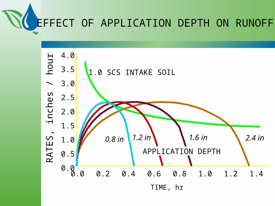
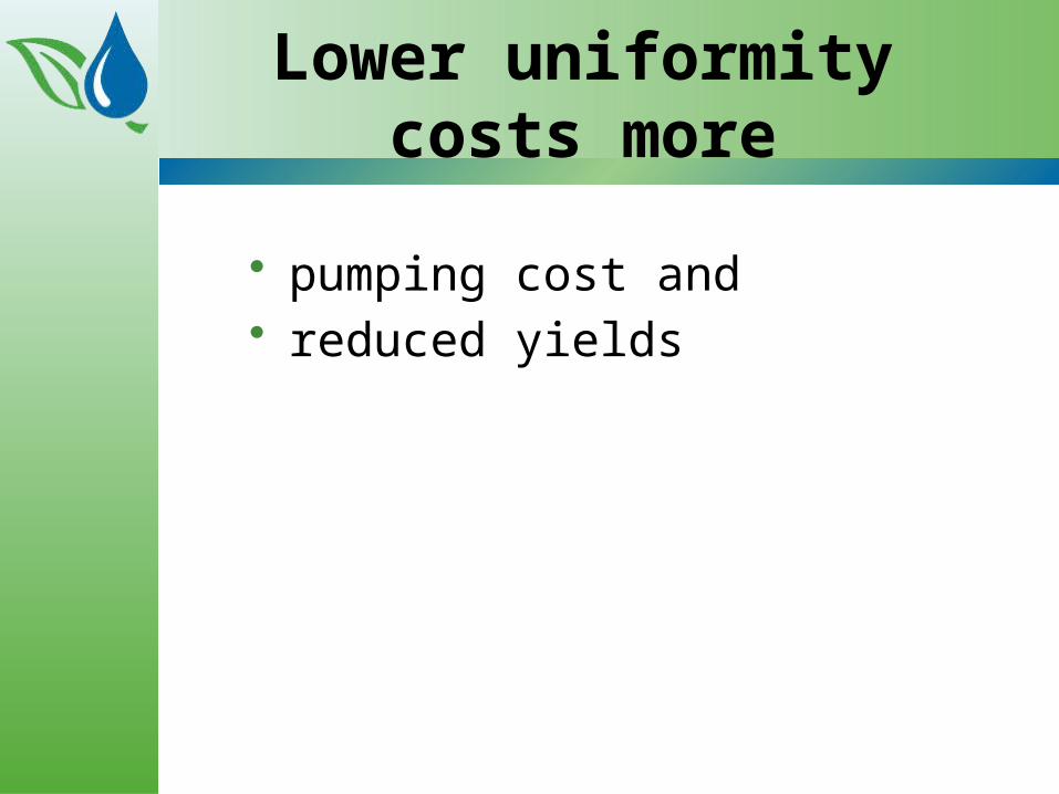
EFFECT OF APPLICATION DEPTH ON RUNOFF
0.0 0.2 0.4 0.6 0.8 1.0 1.2 1.4
4.0
3.5
3.0
2.5
2.0
1.5
1.0
0.5
0.0
1.0 SCS INTAKE SOIL
0.8 in 1.2 in 1.6 in 2.4 in
TIME, hr
RA
TE
S,
inch
es /
hou
r
APPLICATION DEPTH

0 2 4 6 8
8
7
6
5
4
3
2
1
01 3 5 7
20 ft
40 ft
60 ft
100 ft
120 ft
WETTED DIAMETER:
EFFECT OF CAPACITY ON PEAK APPLICATION RATE
SYSTEM CAPACITY, gpm / acre
PE
AK
AP
PL
ICA
TIO
N R
AT
E,
IN/H
R
1300 ft from pivot

Hill side erosion from pivot

HOW TO REDUCE RUNOFF?
1. REDUCE SYSTEM CAPACITY
- irrigate more hours per year
2. REDUCE APPLICATION DEPTH
- make more revolutions per year
3. CHANGE SPRINKLER PACKAGE
- increase wetted radius
- may need higher pressure
4. INCREASE SURFACE STORAGE
- extra tillage
- make changes to pump
- increase chances of getting behind

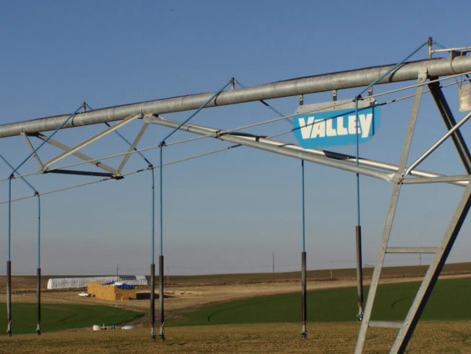
Nozzle Layout
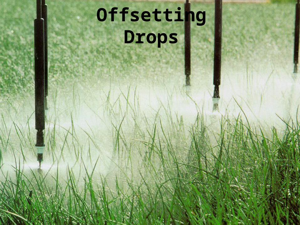
Offsetting Drops
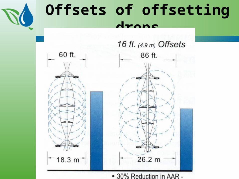
Offsets of offsetting drops

Spray booms on outer spansSpray booms on outer spans
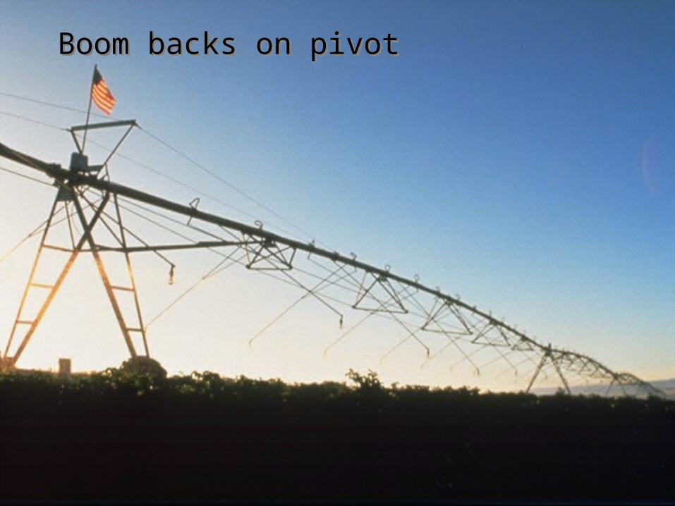
Boom backs on pivotBoom backs on pivot

Boom backs behind towers

Impact of booms on application rate

Methods of increasing Surface Storage
• Basin Tillage• Dammer-diker• Subsoiler• Field cultivator• Rough cloddy ground
(slope dependent)• Organic residue

Dam-DikkerDam-Dikker

Basin/ reservoir tillageBasin/ reservoir tillage

LEPA System

Surface storage from crop residue

© Irrigation Association

Let’s go to our manuals
Pressure Regulation

Determine the Need for Regulators
• Impacts of elevation• Impacts of corner systems and
guns• Cv and hysteresis

Determine the Need for Regulators, cont.
• Minimum pressure losses through regulators
• To regulate or not to regulate

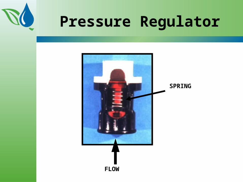
Pressure Regulator
FLOW
SPRING


Practice example
• A system is on a field where elevation changes by 10 feet as the lateral travels around the pivot. The water surface in the ground water well changes by 10 feet over the course of the irrigation season, and an end-gun, when turned on, causes an increase in friction along the lateral of 2 feet.
• If the design pressure of the system is 20 psi, are pressure regulators are recommended? If the design pressure of the system is 50 psi?
•

Determine the Need for
End Guns• Does the system have regulators?• Will the gun be intermittent?• Is there chemigation?

Determine the Need for
End Guns, cont.• Soil intake rate concerns• Base pressure of the pivot• Uniformity and economics

Size the End Gun
• Capacity• Sprinkler arc• Pressure, booster pump• Steep vs. flat curves of main pump

Center Pivots + End Gun
• Inexpensive coverage of field area beyond pivot length
• 80 to 100 psi needed for good coverage.
• Booster pump often used to increase pressure at the end gun (2,5 or 7 hp)Impact driven
Gear driven

• End gun with booster on end of lateral
• and a large sprinkler head
• each is operated separately

© Irrigation Association

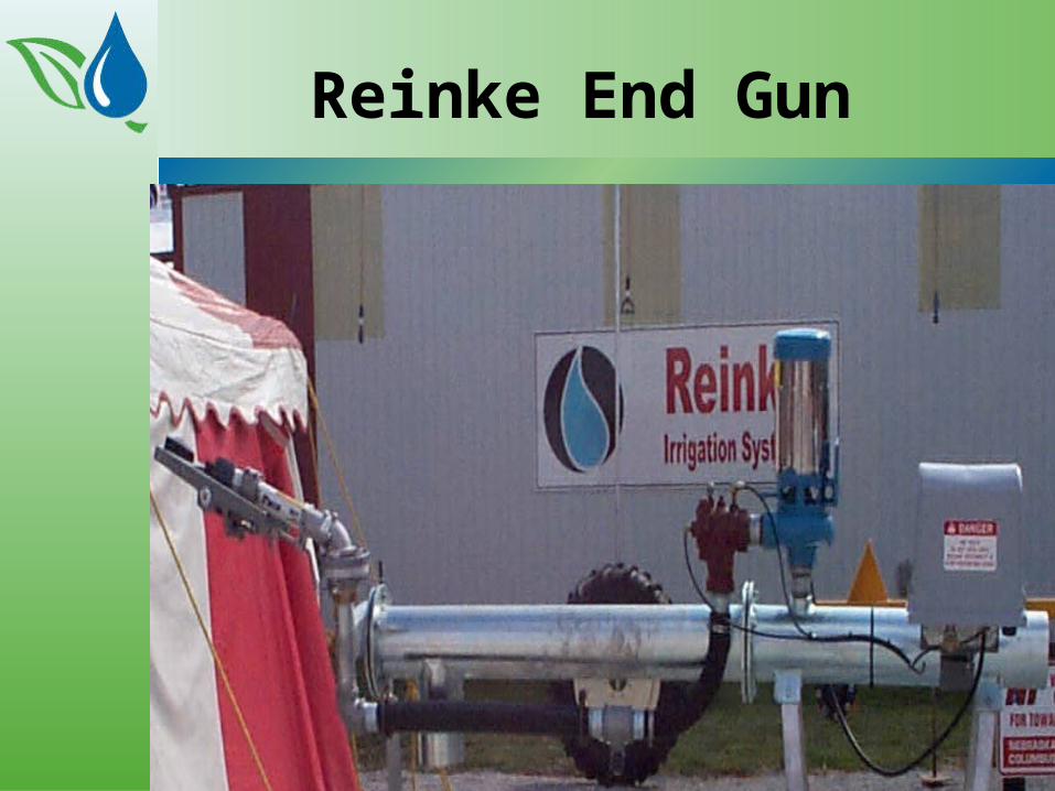
Reinke End Gun
Corner Systems: Are they needed?
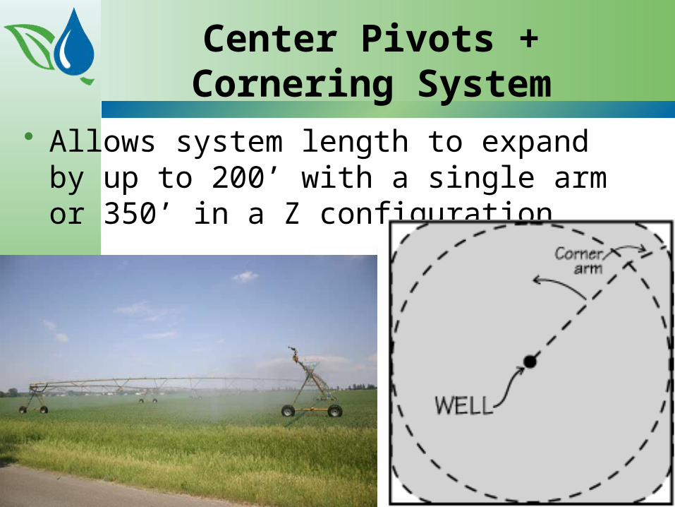
Center Pivots + Cornering System
• Allows system length to expand by up to 200’ with a single arm or 350’ in a Z configuration.
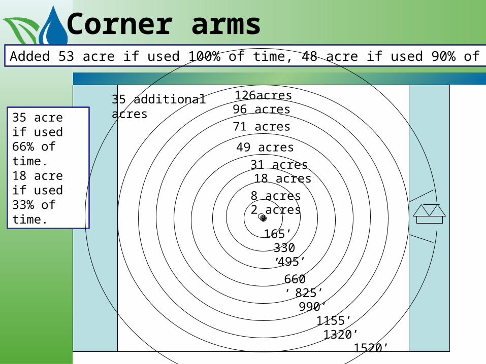
Corner arms
1520’
Added 53 acre if used 100% of time, 48 acre if used 90% of time
35 acre if used 66% of time.18 acre if used 33% of time.
35 additional acres
8 acres
165’330’ 495’
660’ 825’
990’
1320’1155’
2 acres
18 acres31 acres
49 acres
71 acres
96 acres126acres
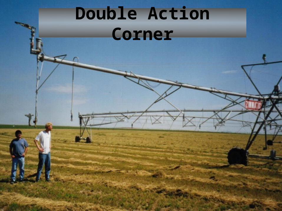
Double Action Corner

© Irrigation Association
© Irrigation Association
Let’s go to our manuals again

End gun on/off switch
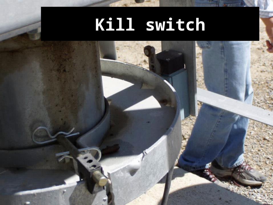
Kill switch

Temperature sensor

Surge proctor

Management Monitoring and Controls
Valley Pro2
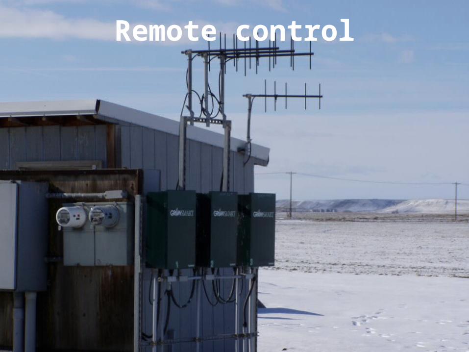
Remote control

RadioLink
PanelLink
AuxiliaryLink
BaseStation2
BaseStation2
Wheel Tracks and rutting
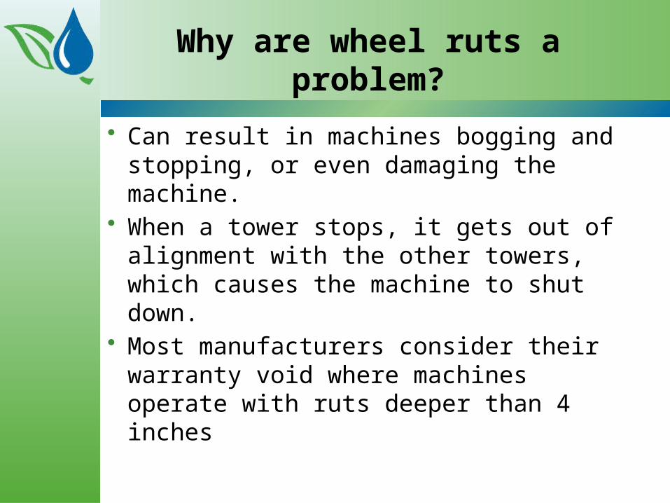
Why are wheel ruts a problem?
• Can result in machines bogging and stopping, or even damaging the machine.
• When a tower stops, it gets out of alignment with the other towers, which causes the machine to shut down.
• Most manufacturers consider their warranty void where machines operate with ruts deeper than 4 inches

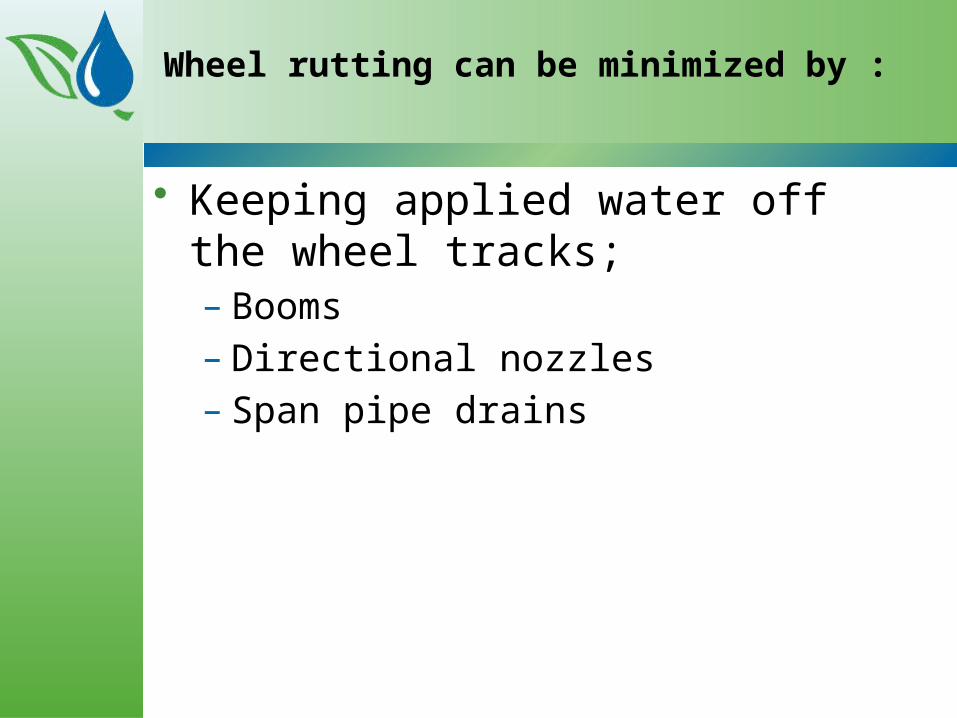
Wheel rutting can be minimized by :
• Keeping applied water off the wheel tracks;– Booms– Directional nozzles– Span pipe drains

Booms at towers

Directional sprays

Span Pipe Drains
• span pipe drain valves, are located at the lowest points on the span pipe.
• whenever the machine stops, much of the water in the span drains onto the wheel track
• Solution– Place a fitting over the valve and
connect a hose to the fitting and fix to the truss rod several feet away to discharge water away from wheel.

Wheel rutting can be minimized by :
• Increasing the load-bearing strength of the soil along the wheel track lines; – PAM– Replace soil
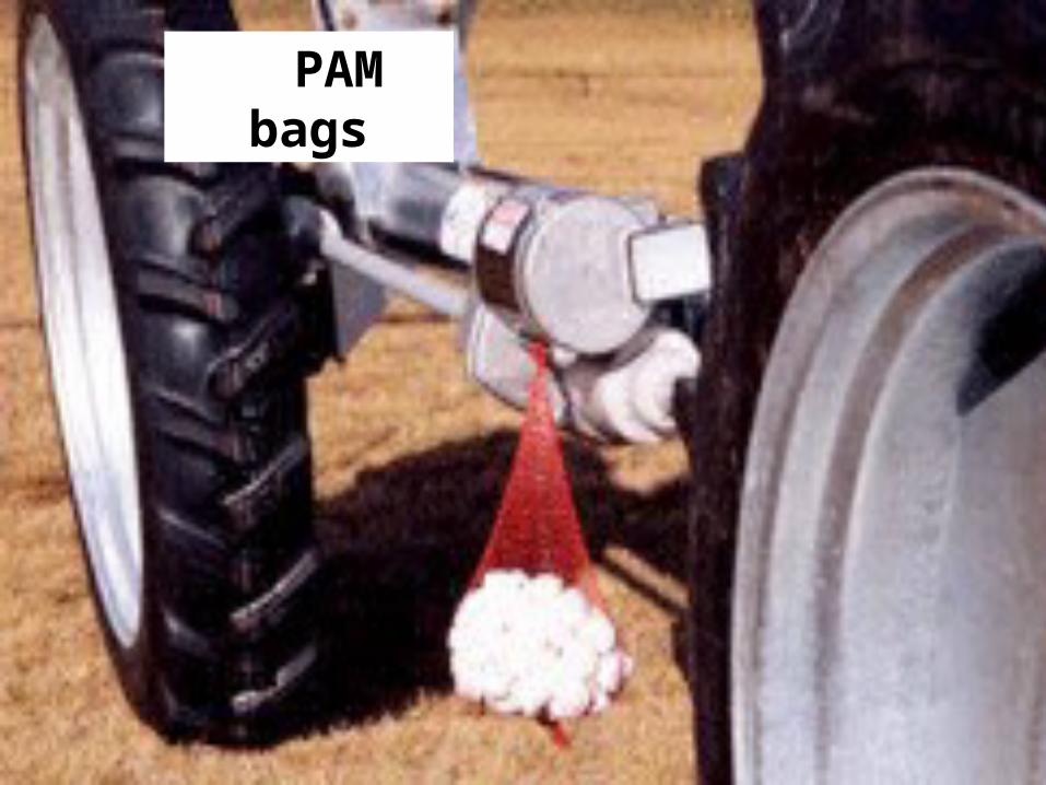
PAM bags
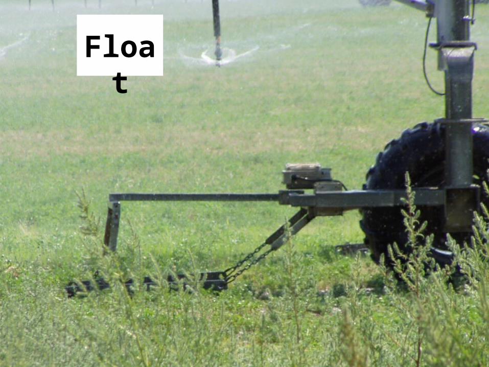
Floa
t
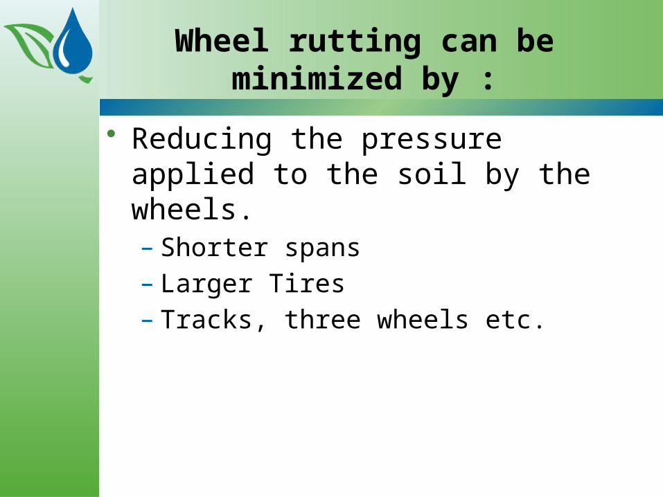
Wheel rutting can be minimized by :
• Reducing the pressure applied to the soil by the wheels.– Shorter spans– Larger Tires– Tracks, three wheels etc.

Tracks


Three wheels