Overhead transmission lines Insulators - Svenska kraftnät · 2 Scope . These guidelines describe...
21
—- SVENSKA KRAFTNÄT T SWEDISH NATIONAL GRID UNIT, BUSINESS AREA AFL, Asset Management Lines TR05-11E OUR REFERENCE DATE 2016-06-09 CONSIJLT, m å(J CONSkJLTATIONS TECHNICAL GUIDELINE REVISION APPROVED 3 Td Overhead transmission lines Insulators Introduction These guidelines describe the requirements on insulators for insulator sets in accord- ance with TR 05-10E for overhead transmission lines with alternating current and cover design and inspection. The guidelines intend to guarantee satisfactory perfor- mance of insulators during the lifetime of the overhead line and shall be used at pur- chasing of insulators. This English text is to be regarded as a translation of the Swedish guideline. The Swe- dish text and the interpretation thereof shall govern the contract and the legal rela- tions between parties. TEKNISK RIKTLINJE 2016-06-09 TR05-11E utg 3 1 (21)
Transcript of Overhead transmission lines Insulators - Svenska kraftnät · 2 Scope . These guidelines describe...
—- SVENSKA KRAFTNÄT
T S W E D I S H N A T I O N A L G R I D
U N I T , B U S I N E S S A R E A
AFL, Asset Management Lines TR05-11E O U R R E F E R E N C E
D A T E
2016-06-09 C O N S I J L T , må(J C O N S k J L T A T I O N S
TECHNICAL GUIDELINE
R E V I S I O N A P P R O V E D
3 Td
Overhead transmission lines Insulators
Introduction These guidelines describe the requirements on insulators for insulator sets in accord-ance with TR 05-10E for overhead transmission lines with alternating current and cover design and inspection. The guidelines intend to guarantee satisfactory perfor-mance of insulators during the lifetime of the overhead line and shall be used at pur-chasing of insulators.
This English text is to be regarded as a translation of the Swedish guideline. The Swe-dish text and the interpretation thereof shall govern the contract and the legal relations between parties.
TEKNISK RIKTLINJE 2016-06-09 TR05-11E utg 3
1 (21)
Notes Change notes Date
1 (A) New template. 09 / 07 / 2008
2 New template. Clause 11.5.2.1 and 11.5.2.3 revised. Clausel 11.9.2.5 revised. Rev. 11.9.2.7.
02 / 04 / 2012
3 New template clause numbers changed. Clause 5.1.6 inserted. Clause 7.1 sample size revised.
09 / 06 / 2016
TEKNISK RIKTLINJE 2016-06-09 TR05-11E
2 (21)
Content
1 References ................................................................................................................. 6
2 Scope .......................................................................................................................... 7
3 Definition ................................................................................................................... 7
4 Description ................................................................................................................ 7
4.1 Ball and socket type disc insulator ............................................................. 7
5 Requirements ............................................................................................................ 7
5.1 General ......................................................................................................... 7 5.1.1 Material ........................................................................................ 8 5.1.2 Insulating part ............................................................................. 8 5.1.3 Couplings ...................................................................................... 8 5.1.4 Cement .......................................................................................... 8 5.1.5 Locking devices ............................................................................. 8 5.1.6 Fog type disc insulator corrosion protection ............................. 8
5.2 Design .......................................................................................................... 8 5.2.1 Measurement ................................................................................ 8 5.2.2 Displacements .............................................................................. 8 5.2.3 Couplings ...................................................................................... 8 5.2.4 Locking devices ............................................................................. 8 5.2.5 Porosity ......................................................................................... 8 5.2.6 Zinc layer ...................................................................................... 8
5.3 Mechanical requirements ............................................................................ 9 5.3.1 Locking system .............................................................................. 9 5.3.2 Electromechanical failing load .................................................... 9 5.3.3 Mechanical failing load ................................................................ 9 5.3.4 Temperature cycling ..................................................................... 9 5.3.5 Thermal shock ............................................................................... 9 5.3.6 Thermal-mechanical failing load................................................. 9 5.3.7 Residual failing load ..................................................................... 9 5.3.8 Impact properties .......................................................................... 9
TEKNISK RIKTLINJE 2016-06-09 TR05-11E
3 (21)
5.3.9 Routine test load ............................................................................ 9 5.4 Electrical requirements ............................................................................... 9
5.4.1 Dry lightning impulse withstand voltage test ............................ 9 5.4.2 Wet power frequency withstand voltage test.............................. 9 5.4.3 Power frequency puncture voltage ............................................ 10 5.4.4 Flash over at fast front over-voltages ....................................... 10 5.4.5 Radio interference ....................................................................... 10
6 Type test ................................................................................................................... 10
6.1 General ....................................................................................................... 10 6.2 Dimensions ................................................................................................. 10 6.3 Displacements ............................................................................................ 10 6.4 Locking system ........................................................................................... 10 6.5 Radio interference ..................................................................................... 10 6.6 Temperature cycling .................................................................................. 11 6.7 Electromechanical failing load ................................................................. 11 6.8 Mechanical failing load ............................................................................. 11 6.9 Porosity ....................................................................................................... 11 6.10 Thickness of zinc coating ........................................................................... 12 6.11 Dry lightning impulse withstand voltage test. ........................................ 12 6.12 Wet power frequency withstand voltage test .......................................... 12 6.13 Thermal shock ............................................................................................ 12 6.14 Power frequency puncture voltage........................................................... 12 6.15 Impact properties ...................................................................................... 12 6.16 Thermal-mechanical performance ........................................................... 12 6.17 Residual strength ....................................................................................... 12
7 Sample test .............................................................................................................. 13
7.1 General ....................................................................................................... 13 7.2 Dimensions ................................................................................................. 14 7.3 Displacements ............................................................................................ 14 7.4 Locking system ........................................................................................... 14 7.5 Temperature cycling .................................................................................. 14 7.6 Electromechanical failing load ................................................................. 14 7.7 Mechanical failing load ............................................................................. 14 7.8 Thermal shock ............................................................................................ 14 7.9 Power frequency puncture voltage........................................................... 15 7.10 Porosity ....................................................................................................... 15
TEKNISK RIKTLINJE 2016-06-09 TR05-11E
4 (21)
7.11 Thickness of zinc coating ........................................................................... 15 7.12 Residual strength ....................................................................................... 15
8 Routine tests ............................................................................................................ 15
8.1 Visual inspection ........................................................................................ 15 8.2 Routine test load ........................................................................................ 15 8.3 Electrical test .............................................................................................. 15
9 Delivery .................................................................................................................... 16
9.1 General ....................................................................................................... 16 9.2 Documentation ........................................................................................... 16
9.2.1 Assembly drawing ...................................................................... 16 9.2.2 List of material ............................................................................ 16 9.2.3 Manufacturing process ............................................................... 16 9.2.4 Quality system ............................................................................. 17 9.2.5 Installation instructions ............................................................. 17 9.2.6 Reports ......................................................................................... 17
9.3 Transport and storing ............................................................................... 17
10 Tables ....................................................................................................................... 18
Table 1A Fog type disc insulators, dimensions (Older type of insulator) .................................................................................................... 18
Table 1B Fog type disc insulators, dimensions ......................................... 18 Table 2 Disc insulators, Electrical and Mechanical Requirements ..................... 19 Table 3 Disc insulators, Type test ......................................................................... 20
11 Figures ..................................................................................................................... 21
Figure 1 Disc insulator ............................................................................... 21
TEKNISK RIKTLINJE 2016-06-09 TR05-11E
5 (21)
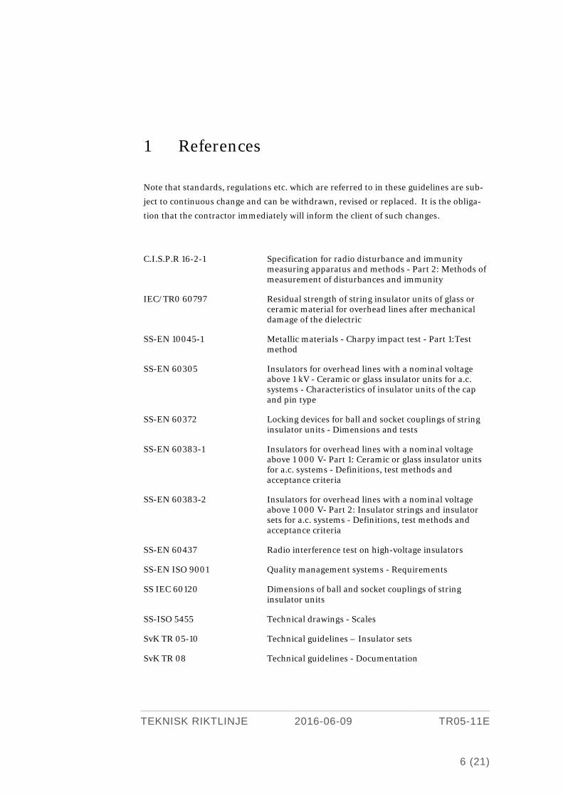
1 References
Note that standards, regulations etc. which are referred to in these guidelines are sub-
ject to continuous change and can be withdrawn, revised or replaced. It is the obliga-
tion that the contractor immediately will inform the client of such changes.
C.I.S.P.R 16-2-1 Specification for radio disturbance and immunity measuring apparatus and methods - Part 2: Methods of measurement of disturbances and immunity
IEC/TR0 60797 Residual strength of string insulator units of glass or ceramic material for overhead lines after mechanical damage of the dielectric
SS-EN 10045-1 Metallic materials - Charpy impact test - Part 1:Test method
SS-EN 60305 Insulators for overhead lines with a nominal voltage above 1 kV - Ceramic or glass insulator units for a.c. systems - Characteristics of insulator units of the cap and pin type
SS-EN 60372 Locking devices for ball and socket couplings of string insulator units - Dimensions and tests
SS-EN 60383-1 Insulators for overhead lines with a nominal voltage above 1 000 V- Part 1: Ceramic or glass insulator units for a.c. systems - Definitions, test methods and acceptance criteria
SS-EN 60383-2 Insulators for overhead lines with a nominal voltage above 1 000 V- Part 2: Insulator strings and insulator sets for a.c. systems - Definitions, test methods and acceptance criteria
SS-EN 60437 Radio interference test on high-voltage insulators
SS-EN ISO 9001 Quality management systems - Requirements
SS IEC 60120 Dimensions of ball and socket couplings of string insulator units
SS-ISO 5455 Technical drawings - Scales
SvK TR 05-10 Technical guidelines – Insulator sets
SvK TR 08 Technical guidelines - Documentation
TEKNISK RIKTLINJE 2016-06-09 TR05-11E
6 (21)
2 Scope
These guidelines describe the requirements on insulators for insulator sets in accord-
ance with TR 05-10E for overhead transmission lines with alternating current and
cover design and inspection.
The guidelines intend to guarantee satisfactory performance of insulators during the
lifetime of the overhead line and shall be used at purchasing of insulators.
3 Definition
Technical terms and definitions used in these guidelines:
Residual breaking load
Breaking load of insulators with the shed of the insulating part cracked or completely
broken off.
4 Description
4.1 Ball and socket type disc insulator Individual insulators with the insulating part shaped as a dish made from porcelain or
glass with sockets shaped as into a cap and a pin with an end ball made from metal.
See SS-EN 60305.
5 Requirements
5.1 General Insulators shall be able to withstand the mechanical stresses which can occur during
transport, handling and installation at temperatures as low as –40 °C, in addition to
the mechanical stresses which can occur during the lifetime of the overhead line at
temperatures from -50 °C to +100 °C.
TEKNISK RIKTLINJE 2016-06-09 TR05-11E
7 (21)
5.1.1 Material
5.1.2 Insulating part Disc insulators shall have insulating parts made from toughened glass.
5.1.3 Couplings Caps with sockets shall be made from malleable cast iron, spheroidal graphite iron or
forged steel and be hot dip galvanised.
Pins with end balls shall be made from forged steel and be hot dip galvanised.
5.1.4 Cement Cement for assembling shall be aluminous cement.
5.1.5 Locking devices Locking devices shall be made from bronze, copper alloy with not more than 15 % zinc
content or austenitic stainless steel.
5.1.6 Fog type disc insulator corrosion protection Fog type disc insulator shall be equipped with a corrosion protection zinc sleeve.
5.2 Design
5.2.1 Measurement Disc insulators with normal creepage distances shall have measurements in accord-
ance with SS-EN 60305.
Disc insulators with extended creepage distances shall have measurements in accord-
ance with Table 1.
5.2.2 Displacements The maximum axial and radial displacement shall conform to SS-EN 60383-1.
5.2.3 Couplings Balls and sockets shall conform to SS-IEC 60120. However size 16B shall not be used.
5.2.4 Locking devices Locking devices shall conform to SS-EN 60372. However W-clips are not to be used
5.2.5 Porosity Porcelain porosity shall conform to the requirements of SS-EN 60383-1.
5.2.6 Zinc layer The thickness of the zinc layer shall conform to the requirements of SS-EN 60383-1.
TEKNISK RIKTLINJE 2016-06-09 TR05-11E
8 (21)
5.3 Mechanical requirements
5.3.1 Locking system The locking system shall conform to the requirements of SS-EN 60372.
5.3.2 Electromechanical failing load Insulators made from porcelain shall conform to the electromechanical failing load
requirements of SS-EN 60305, see Table 2.
5.3.3 Mechanical failing load Insulators made from toughened glass shall conform to the mechanical failing load
requirements of SS-EN 60305, see Table 2.
5.3.4 Temperature cycling Insulators made from porcelain shall conform to the temperature cycling requirements
of SS-EN 60383-1.
5.3.5 Thermal shock Insulators made from toughened glass shall conform to the requirements for thermal
shock in accordance with SS-EN 60383-1.
5.3.6 Thermal-mechanical failing load Insulators shall conform to the thermal-mechanical performance requirements of SS-
EN 60383-1, see Table 2.
5.3.7 Residual failing load Insulators shall conform to the residual failing load requirements of Table 2.
5.3.8 Impact properties Insulator pins shall conform to the impact property requirements of Table 2.
5.3.9 Routine test load Insulators shall conform to the routine test load requirements of Table 2.
5.4 Electrical requirements
5.4.1 Dry lightning impulse withstand voltage test Insulators made from toughened glass or porcelain shall conform to the dry lightning
impulse withstand voltage requirements of Table 2.
5.4.2 Wet power frequency withstand voltage test Insulators made from toughened glass or porcelain shall conform to the wet power
frequency withstand voltage requirements of Table 2.
TEKNISK RIKTLINJE 2016-06-09 TR05-11E
9 (21)
5.4.3 Power frequency puncture voltage Insulators made from toughened glass or porcelain shall conform to the power fre-
quency puncture voltage requirements of Table 2.
5.4.4 Flash over at fast front over-voltages Insulators shall conform to the flashover requirements with fast front over-voltages.
5.4.5 Radio interference The radio interference level for insulators shall be determined at 20 kV respectively 24
kV 50 Hz alternating current (r.m.s. value) over 1 µV interference voltage and 500 kHz
measuring frequency. The radio interference level shall comply with the requirements
of acceptance level C20 ≥ 1,6 at 20 kV respectively C24 ≥ 1,2 at 24 kV.
6 Type test
6.1 General Unless otherwise agreed type tests shall be performed in accordance with Clauses 6.2-
6.17 on the number of samples as given in Tables 3.
The tests shall be performed in such a way that neither the method nor the equipment
affects the result.
6.2 Dimensions The number of insulators to be tested is given in Table 3.
The tests shall be performed on disc insulators according to SS-EN 60383-1.
6.3 Displacements The number of insulators to be tested is given in Table 3.
For disc insulators the tests shall be performed in accordance with SS-EN 60383-1.
6.4 Locking system The number of insulators to be tested is given in Table 3.
The tests shall be performed in accordance with SS-EN 60383-1.
6.5 Radio interference The number of insulators to be tested is given in Table 3.
TEKNISK RIKTLINJE 2016-06-09 TR05-11E
10 (21)
The test shall, on cap & pin insulators, be performed with 20 kV respectively 24 kV 50
Hz alternating current (r.m.s. value) over 1 µV interference voltage and 500 kHz
measuring frequency at test in accordance with C.I.S.P.R 16-2-1 and SS-EN 60437.
From the individual interference levels X measured at the test shall the mean value X
and the standard deviation σn-1 be calculated.
where
X20 = mean value of the lot at 20 kV [dB] X24 = mean value of the lot at 24 kV [dB] σ20 = standard deviation of the lot at 20 kV [dB] σ24 = standard deviation of the lot at 24 kV [dB] C20 = acceptance level at 20 kV C24 = acceptance level at 24 kV The insulators is considered to meet the requirements if: X20 ≤ 60 – 1,6σ20 and X24 ≤ 60 – 1,2σ24.
6.6 Temperature cycling The number of insulators to be tested is given in Table 3.
The tests shall be performed in accordance with SS-EN 60383-1 for insulators made
from porcelain.
6.7 Electromechanical failing load The number of insulators to be tested is given in Table 3.
The tests shall be performed in accordance with SS-EN 60383-1 for disc insulators
made from porcelain.
6.8 Mechanical failing load The number of insulators to be tested is given in Table 3.
The tests shall be performed in accordance with SS-EN 60383-1 for disc insulators
made from glass.
6.9 Porosity The number of insulators to be tested is given in Table 3.
TEKNISK RIKTLINJE 2016-06-09 TR05-11E
11 (21)
The tests shall be performed in accordance with SS-EN 60383-1 for insulators made
from porcelain.
6.10 Thickness of zinc coating The number of insulators to be tested is given in Table 3.
The tests shall be performed in accordance with SS-EN 60383-1.
6.11 Dry lightning impulse withstand voltage test. The number of insulators to be tested is given in Table 3.
The tests shall be performed in accordance with SS-EN 60383-2 on an assembled insu-
lator string consisting of 5 disc insulators or alternatively one composite insulator.
6.12 Wet power frequency withstand voltage test The number of insulators to be tested is given in Table 3.
The tests shall be performed in accordance with SS-EN 60383-2 on an assembled insu-
lator string consisting of 5 disc insulators or alternatively one composite insulator.
6.13 Thermal shock The number of insulators to be tested is given in Table 3.
The tests shall be performed in accordance with SS-EN 60383-1 for disc insulators
made from toughened glass.
6.14 Power frequency puncture voltage The number of insulators to be tested is given in Table 3.
The tests shall be performed in accordance with SS-EN 60383-1 for disc insulators.
6.15 Impact properties The number of insulators to be tested is given in Table 3.
The tests shall be performed in accordance with SS-EN 10045-1.
6.16 Thermal-mechanical performance The number of insulators to be tested is given in Table 3.
The tests shall be performed in accordance with SS-EN 60383-1.
6.17 Residual strength The number of insulators to be tested is given in Table 3.
TEKNISK RIKTLINJE 2016-06-09 TR05-11E
12 (21)
The tests shall be performed in accordance with IEC/TR0 60797 for disc insulators.
7 Sample test
7.1 General Sample tests shall be carried out by the manufacturer on insulators selected at random
from the lot to be supplied.
Test samples shall be supplied by the manufacturer free of charge to the client and
shall not be included in the lot to be supplied.
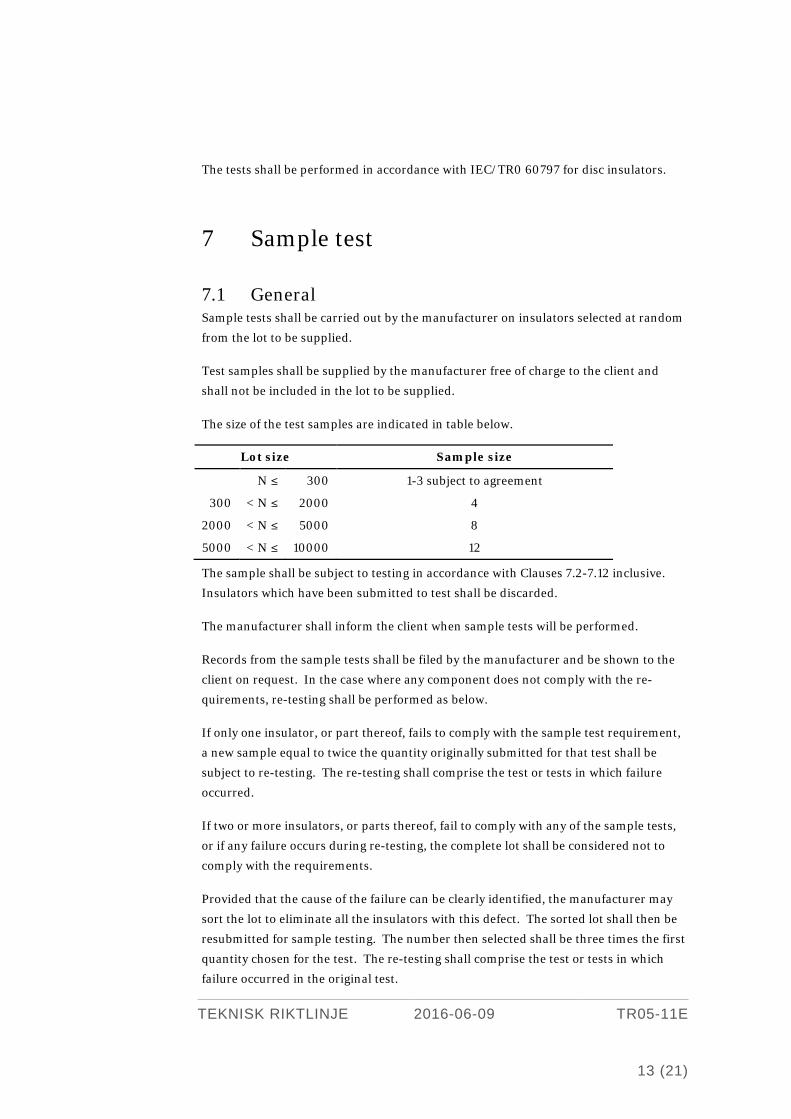
The size of the test samples are indicated in table below.
Lot size Sample size
N ≤ 300 1-3 subject to agreement
300 < N ≤ 2000 4
2000 < N ≤ 5000 8
5000 < N ≤ 10000 12
The sample shall be subject to testing in accordance with Clauses 7.2-7.12 inclusive.
Insulators which have been submitted to test shall be discarded.
The manufacturer shall inform the client when sample tests will be performed.
Records from the sample tests shall be filed by the manufacturer and be shown to the
client on request. In the case where any component does not comply with the re-
quirements, re-testing shall be performed as below.
If only one insulator, or part thereof, fails to comply with the sample test requirement,
a new sample equal to twice the quantity originally submitted for that test shall be
subject to re-testing. The re-testing shall comprise the test or tests in which failure
occurred.
If two or more insulators, or parts thereof, fail to comply with any of the sample tests,
or if any failure occurs during re-testing, the complete lot shall be considered not to
comply with the requirements.
Provided that the cause of the failure can be clearly identified, the manufacturer may
sort the lot to eliminate all the insulators with this defect. The sorted lot shall then be
resubmitted for sample testing. The number then selected shall be three times the first
quantity chosen for the test. The re-testing shall comprise the test or tests in which
failure occurred in the original test.
TEKNISK RIKTLINJE 2016-06-09 TR05-11E
13 (21)
If any insulator, or part there-of of the sorted lot, fails during this re-testing, the com-
plete lot shall be considered as not complying with the requirements.
7.2 Dimensions Number of insulators to be tested: E1 & E2.
The tests shall be performed in accordance with SS-EN 60383-1.
7.3 Displacements Numbers of insulators to be tested: E1 & E2.
The tests shall be performed on disc insulators in accordance with SS-EN 60383-1.
7.4 Locking system Numbers of insulators to be tested: E1 & E2.
The tests shall be performed in accordance with SS-EN 60383-1.
7.5 Temperature cycling Numbers of insulators to be tested: E1 & E2.
The tests shall be performed in accordance with SS-EN 60383-1 for insulators made
from porcelain.
7.6 Electromechanical failing load Number of insulators to be tested: E1.
The tests shall be performed in accordance with SS-EN 60383-1 for disc insulators
made from porcelain.
7.7 Mechanical failing load Number of insulators to be tested: E1.
The tests shall be performed in accordance with SS-EN 60383-1 for disc insulators
made from glass.
7.8 Thermal shock Number of insulators to be tested: E2.
The tests shall be performed in accordance with SS-EN 60383-1 for disc insulators
made from toughened glass.
TEKNISK RIKTLINJE 2016-06-09 TR05-11E
14 (21)
7.9 Power frequency puncture voltage Number of insulators to be tested: E2.
The tests shall be performed in accordance with SS-EN 60383-1 for disc insulators.
7.10 Porosity Number of insulators to be tested: E1.
The tests shall be performed in accordance with SS-EN 60383-1 for insulators made
from porcelain.
7.11 Thickness of zinc coating Number of insulators to be tested: E2.
The tests shall be performed in accordance with SS-EN 60383-1.
7.12 Residual strength Number of insulators to be tested: E3.
The tests shall be performed in accordance with IEC/TR0 60797 for disc insulators.
8 Routine tests
8.1 Visual inspection All insulators shall be visually inspected.
The visual inspection shall be performed in accordance with SS-EN 60383-1 for disc
insulators.
8.2 Routine test load All insulators shall be tested.
The tests shall be performed in accordance with SS-EN 60383-1 for disc insulators.
8.3 Electrical test All insulators shall be tested.
The tests shall be performed in accordance with SS-EN 60383-1 for disc insulators
made from porcelain.
TEKNISK RIKTLINJE 2016-06-09 TR05-11E
15 (21)

9 Delivery
9.1 General The client shall, according to these guidelines, approve the insulators before delivery.
For approval the manufacturer shall demonstrate that the insulators conform to these
guidelines.
The manufacturer shall provide documentation in accordance with Clauses 9.2.1 -
9.2.6 for approval.
The approval of drawings by the client does not release the manufacturer from his
obligations regarding the insulators complying with these guidelines.
All documentation shall be written in Swedish or English.
9.2 Documentation General requirements for documentation see SvK TR 08E.
9.2.1 Assembly drawing The assembly drawing shall have a minimum of two views at an appropriate scale in
accordance with SS-ISO 5455. On the drawing shall be given:
• Type and/or Catalogue number
• Principal dimensions
• Failing load
• Electrical data
• Creepage distance
• All marking
• Weight
• List of materials
9.2.2 List of material Description of material in included parts.
9.2.3 Manufacturing process Description of the manufacturing process
TEKNISK RIKTLINJE 2016-06-09 TR05-11E
16 (21)
9.2.4 Quality system Quality system in accordance with SS-EN ISO 9001.
9.2.5 Installation instructions Installation instructions in Swedish or English with the required drawings.
9.2.6 Reports Report in accordance with Clause 6 Type test report, 7 Sample test report and 8 Rou-
tine tests report.
9.3 Transport and storing The insulators shall be packed up in that way that they will not be damaged or fouled
at transport, construction and at storing.
TEKNISK RIKTLINJE 2016-06-09 TR05-11E
17 (21)
10 Tables
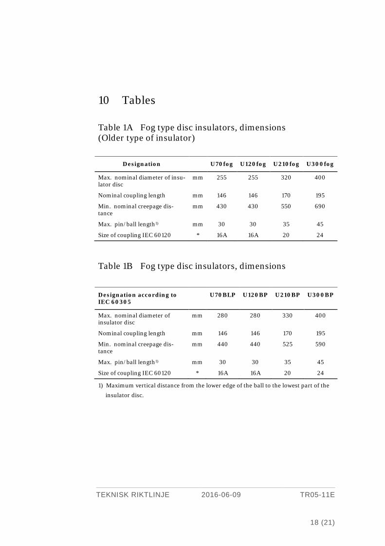
Table 1A Fog type disc insulators, dimensions (Older type of insulator)
Table 1B Fog type disc insulators, dimensions
Designation according to IEC 60305
U70BLP U120BP U210BP U300BP
Max. nominal diameter of insulator disc
mm 280 280 330 400
Nominal coupling length mm 146 146 170 195
Min. nominal creepage dis-tance
mm 440 440 525 590
Max. pin/ball length1) mm 30 30 35 45
Size of coupling IEC 60120 * 16A 16A 20 24
1) Maximum vertical distance from the lower edge of the ball to the lowest part of the
insulator disc.
Designation U70fog U120fog U210fog U300fog
Max. nominal diameter of insu-lator disc
mm 255 255 320 400
Nominal coupling length mm 146 146 170 195
Min. nominal creepage dis-tance
mm 430 430 550 690
Max. pin/ball length1) mm 30 30 35 45
Size of coupling IEC 60120 * 16A 16A 20 24
TEKNISK RIKTLINJE 2016-06-09 TR05-11E
18 (21)
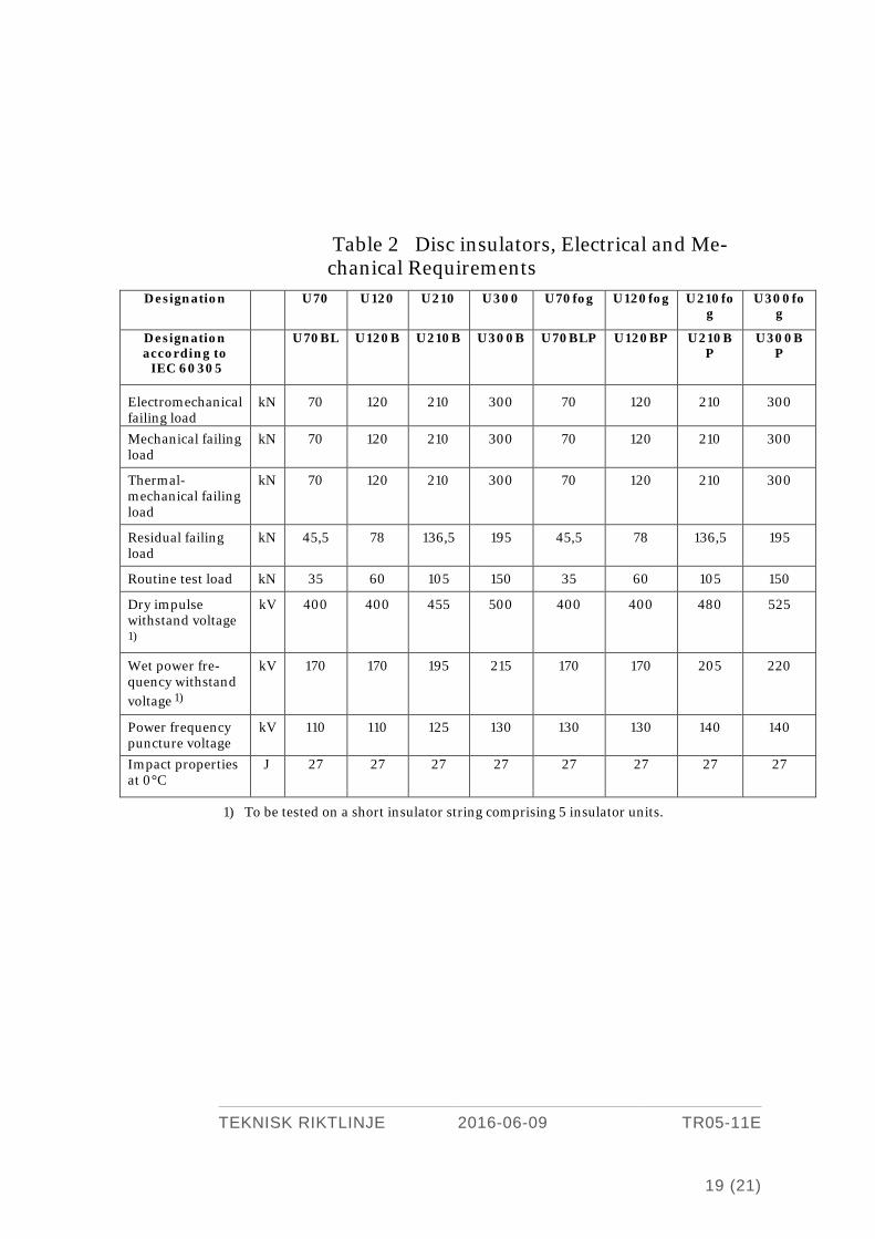
Table 2 Disc insulators, Electrical and Me-chanical Requirements
1) To be tested on a short insulator string comprising 5 insulator units.
Designation U70 U120 U210 U300 U70fog U120fog U210fog
U300fog
Designation according to IEC 60305
U70BL U120B U210B U300B U70BLP U120BP U210BP
U300BP
Electromechanical failing load
kN 70 120 210 300 70 120 210 300
Mechanical failing load
kN 70 120 210 300 70 120 210 300
Thermal-mechanical failing load
kN 70 120 210 300 70 120 210 300
Residual failing load
kN 45,5 78 136,5 195 45,5 78 136,5 195
Routine test load kN 35 60 105 150 35 60 105 150
Dry impulse withstand voltage
1)
kV 400 400 455 500 400 400 480 525
Wet power fre-quency withstand voltage 1)
kV 170 170 195 215 170 170 205 220
Power frequency puncture voltage
kV 110 110 125 130 130 130 140 140
Impact properties at 0°C
J 27 27 27 27 27 27 27 27
TEKNISK RIKTLINJE 2016-06-09 TR05-11E
19 (21)
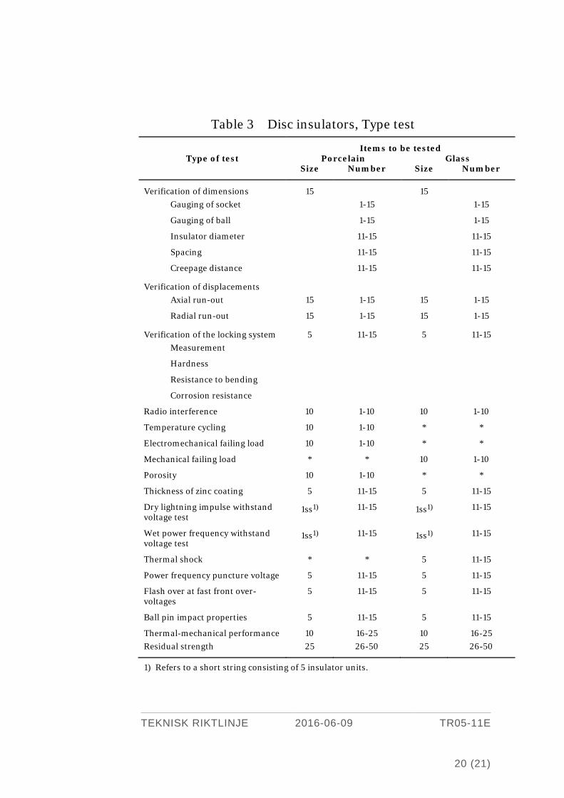
Table 3 Disc insulators, Type test
1) Refers to a short string consisting of 5 insulator units.
Items to be tested Type of test Porcelain Glass
Size Number Size Number
Verification of dimensions 15 15 Gauging of socket 1-15 1-15
Gauging of ball 1-15 1-15
Insulator diameter 11-15 11-15
Spacing 11-15 11-15
Creepage distance 11-15 11-15
Verification of displacements Axial run-out 15 1-15 15 1-15
Radial run-out 15 1-15 15 1-15
Verification of the locking system 5 11-15 5 11-15 Measurement
Hardness
Resistance to bending
Corrosion resistance
Radio interference 10 1-10 10 1-10
Temperature cycling 10 1-10 * *
Electromechanical failing load 10 1-10 * *
Mechanical failing load * * 10 1-10
Porosity 10 1-10 * *
Thickness of zinc coating 5 11-15 5 11-15
Dry lightning impulse withstand voltage test
1ss1) 11-15 1ss1) 11-15
Wet power frequency withstand voltage test
1ss1) 11-15 1ss1) 11-15
Thermal shock * * 5 11-15
Power frequency puncture voltage 5 11-15 5 11-15
Flash over at fast front over-voltages
5 11-15 5 11-15
Ball pin impact properties 5 11-15 5 11-15
Thermal-mechanical performance 10 16-25 10 16-25 Residual strength 25 26-50 25 26-50
TEKNISK RIKTLINJE 2016-06-09 TR05-11E
20 (21)
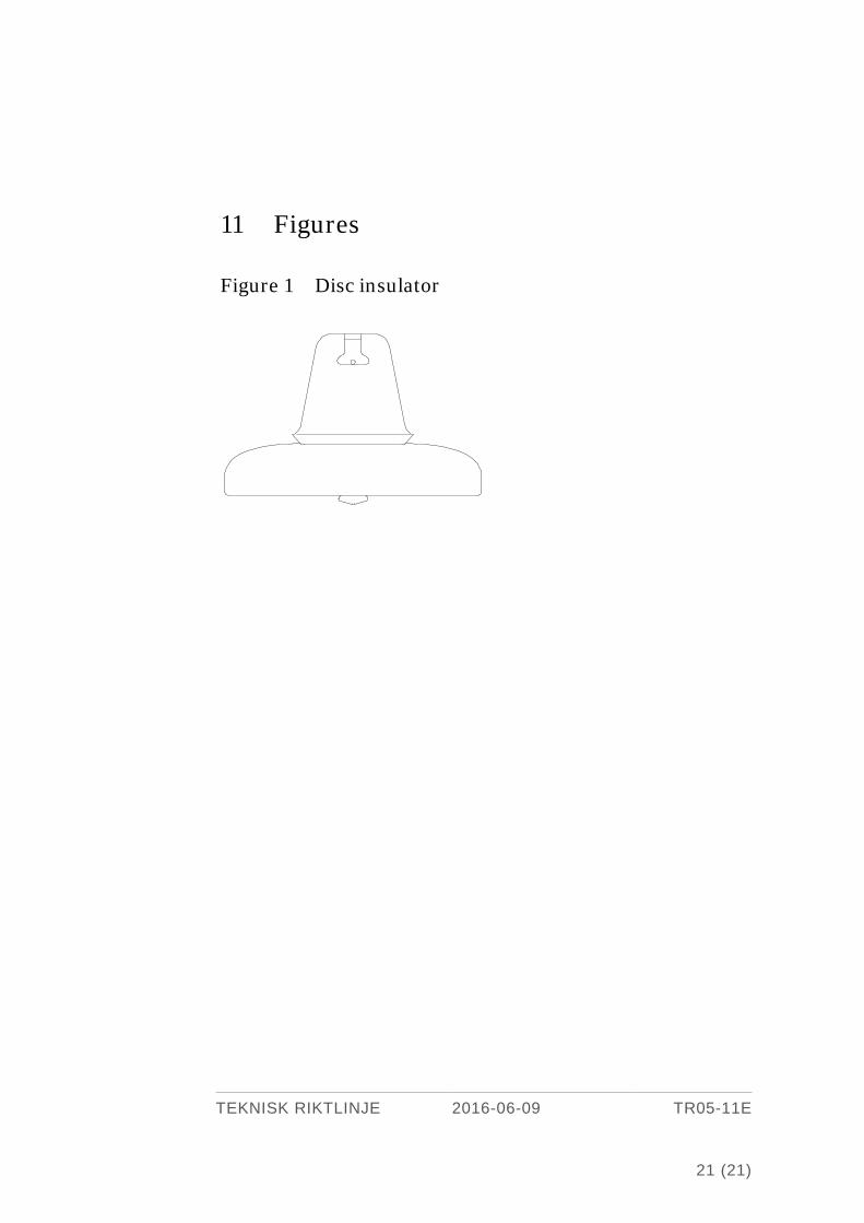
11 Figures
Figure 1 Disc insulator
TEKNISK RIKTLINJE 2016-06-09 TR05-11E
21 (21)