Overhauled Dry Air Pump Owners Manual - Aero Accessories, Inc
25
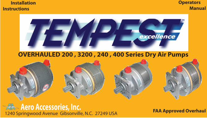
Aero Accessories, Inc. 1240 Springwood Avenue Gibsonville, N.C. 27249 USA TM FAA Approved Overhaul Operators Manual Installation Instructions excellence OVERHAULED 200 , 3200 , 240 , 400 Series Dry Air Pumps TM excellence
Transcript of Overhauled Dry Air Pump Owners Manual - Aero Accessories, Inc
Aero Accessories, Inc.1240 Springwood Avenue Gibsonville , N.C. 27249 Tel.- 336-449-5054 800-322-3200 Fax.-336-449-5461Tempest Overhauled Dry Air Pumps are overhauled by Aero Accessories, Inc. in the USA
TM
Overhauled Dry Air Pump Warranty:Dry Air Pumps overhauled by Aero Accessories, Inc. are warranted against defects in materials and/or workmanshipfor the time periods listed below by model/series number. Aero Accessories, Inc. obligation under this warranty islimited to the repair or replacement at Aero Accessories, Inc. sole descretion any pump that upon inspection byAero Accessories, Inc is found to be defective in materials or workmanship.
211,212,215,216,3215,3216 & -9 Mods241,242 All - Models441, 442 All - Models
2 years or 1000 Hours from Time of Installation1 year or 400 Hours from Time of Installation1 year or 400 Hours from Time of Installation
TM
24
!!! IMPORTANT POINTS ABOUT DRY AIR PUMPS !!!1. Dry Air Pumps are just that, INTERNALLY DRY. Dry air pumps use the graphite dust produced by the gradual wear of the internal vanes as lubrication. Any oil leak, however slight, that permits oil to reach the drive end of the pump may cause internal oil contamination. This contamination combines with the lubricating dust and forms a gummy mixture that binds up the internal components of the pump leading to failure.
2. When cleaning an engine with solvent or soap and water, use a waterproof material to cover the entire dry air pump(s), the pneumatic air �lter and regulator(s). Contamination from solvent or water saturation of these areas may be ingested into the pump causing failure in the much the same way as oil contamination.
3. When a pump fails, vacuum that is present in the inlet hose may suck small particles of carbon up into the hose, even as far as the regulator. (Pressure systems, the inlet �lter will become contaminated.) Hoses and regulator(s) should be removed throughly cleaned and �lters replaced. Particles from the previous failed pump can contaminate the replacement pump and cause FOD damage leading to failure.
4. Te�on tape or other thread compound on threaded �ttings or port threads may be ingested into the pump. These substances will bind up lubrication dust and cause FOD damage leading to failure. It is not necessary to use any type of sealant on �tting threads or port threads.
NOTE: More than 95% of dry air pump failures are the result of one or moreof the above points!
FINAL SYSTEMS CHECK - After new pump is installed and secured, before running engine to check pneumatic system, inspectall hoses, �lters, and regulator(s) for proper installation.Run engine(s) and check operation to verify that pneumatic system is operating within aircraft speci�cations. (Refer to Aircraft Service / Maintenance Manual.)
CAUTION: WHEN INSTALLING PUMP FITTINGS, SECURE PUMP IN VISE BY DRIVE END PAD AS SHOWN IN FIG. 13. SECURING PUMP BY PUMPING CHAMBER, FIG. 14, COULD AFFECT INTERNAL CLEARANCES CAUSING PUMP FAILURE.
4. Install pump with new mounting gasket and, if required a LRT Diverter.
5. Secure pump with proper mounting hardware and tighten. (Refer to Aircraft Engine Service / Maintenance Manual for speci�ed torque requirements.)
6. Attach hose to correct �ttings, being careful not to cut the I.D. of the hoses when sliding over end of �ttings. Secure hoses with proper hardware.
23
DRY AIR PUMP INSTALLATION -1. Before installing replacement pump, con�rm it is the correct model for the application.
2. Perform maintenance check of �ttings, hoses, regulator(s) and �lters.
NOTE: If previous pump has failed prematurely, perform maintenance system check toinsure all components of the pneumatic system are functional and working correctly.
CAUTION: AIRCRAFT WITH DUAL DRY AIR PUMPS MAY LOSE REDUNDANCY FEATURE IF THEMANIFOLD / CHECK VALVE IS NOT FUNCTIONING PROPERLY.
3. With replacement pump gripped by the mounting �ange in vise (Fig. 13) install �ttings into ports �nger-tight. (Use NO Pipe Sealant or Tape on threads.) Tighten with proper wrench, no more than one (1) full turn to required position. Do Not grip pump by the sides of the pumping chamber (Fig. 14).
Figure 13 Figure 14 22
F.
G.
Vacuum Regulator -
Regulator, Valves and Deice Valves -
Regulator must be clean, oil free and in airworthy condition for proper operation. Replace regulator �lter afterinstalling new pump or every 100 hours or annually.Run engine and check for proper operation of regulator. (Refer to Aircraft Service / Maintenance Manual) adjustas necessary for correct vacuum setting for your aircraft. (TempestTM Regulators should require no �eldadjustment, contact Aero Accessories, Inc. if a TempestTM regulator gives an indication of improper operation.)
Before installing a replacement dry air pump, particularly if old pump has failed prematurely, the followingguidelines must be accomplished.1. Determine if pnuematic system problem was cause of failure. This can be accomplished using a commercially available test kit. (Contact Aero Accessories, Inc. for test kit information.)2. Test aircraft’s pneumatic system according to outlined instructions supplied with test kit and the Aircraft Service / Maintenance Manual.3. Any regulator, valve or deice valve found to be defective must be replaced in accordance with the Aircraft Service / Maintenance Manual to prevent possible premature failure of new pump after installation on aircraft.
H. Manifolds / Check Valves - Manifolds and check valves have internal rubber components that can deteriorate from age becoming hard andbrittle, and lose their sealing capacity. (Refer to Aircraft Service / Maintenance Manual for manifolds, checkvalves inspection intervals and procedures.)
21
20
D.
E.
Pump Fittings -
Hoses -
1. Inspect for damage and cleanliness.2. Bent or kinked �ttings (Figure 12) can reduce air �ow.3. Check threads for damage, replace if necessary.4. Clean �ttings inside and out to remove any loose debris.5. Install �ttings as described in Section ‘Dry Air Pump Installation’.
Remove and inspect hoses for the following conditions;1. Hard, Cracked, Brittle, or Oil Contaminated.2. Determine if liner separation has occurred inside of hose. Liner separation can restrict air �ow. (Replace hose if any one of these conditions is found.)3. If replacing a previously failed pump, throughly clean inside of hoses , making sure all loose debris have been removed before attaching hoses.
NOTE: PUMPS INTERNAL CLEARANCES WILL NOT ALLOW FOREIGN PARTICLES TO PASS THOUGHWITHOUT CAUSING DAMAGE OR FAILURE. MAKE SURE HOSES ARE CLEAN.
Figure 12
19
PNEUMATIC SYSTEM MAINTENANCE
A.
B.
C.
Oil Leaks -
Oil Seal - Inspect drive pad seal, it should be dry. If any oil is found replace the oil seal. (Refer to enginemanufacturer’s parts manual for correct seal part number and installation instructions.)RECOMENDATION: If a replacement pump is being installed on a midtime engine, replace the oil seal evenif area is dry. The oil seal could start leaking before engine TBO is reached.
Clean �lters are essential for a pneumatic system to operate properly. Dirty �lters can reduce air �ow topump causing the pump to operate at higher temperatures and increasing pump wear. Dirty �lters cana�ect operation of pneumatic instruments and regulator(s) and can cause low vacuum or low or excessive pressure.NOTE: REFER TO AIRCRAFT MAINTENANCE/SERVICE MANUAL FOR FILTER REPLACEMENT SCHEDULE.
Inspect engine and engine compartment for oil leaks that could contaminate the dry air pump or reachthe inlet �lter on pressure systems or the vacuum regulator, if located in the engine compartment.
On Cessna 150 / Continental O-200 and some other engines the pump mounts with the drive shaft vertical. Pumps designed for vertical installation such as the AA3215CC-9, AA215CC-9, or AA211CC-9 are normally required. When installing an AA3215CC-9 the open channel should face aft towards the �rewall and away from sources of oil contami-nation. On Cessna 172’s having 2 pumps on the engine, the lower pump mounts with the ports slightly rotated at about 20 degrees. The channel pointing closest to the ground should be left open.
The photographs below show the inlet and outlet ports at the 6:00 and 3:00 positions. Notice that in both picturesthe bottom channel is open and pointing towards the ground. The LRT diverter MUST be installed so that the lower drain channel of the mounting �ange remains open and pointing towards the ground.
NOTE:
Ports at 6:00 PositionLRT on TOP
Ports at 3:00 Position(from pilots view)
LRT on TOP
Leave Channel pointing towards the
ground Open.
LRT DiverterInstalled
Figure 1117
Ports at 12:00 PositionLRT on TOP
Ports at 9:00 Position(from pilot’s view)
LRT on TOPLRT DiverterInstalled
Channel Pointingtowards bottom
(ground)Leave Open
Most dry air pumps are installed with the inlet and outlet ports in the 12:00, 3:00, 6:00, or 9:00 positions.Tornado pumps have four (4) exit channels in the mounting �ange face. When a pump is installed on an aircraft the three (3) upper-most channels MUST be plugged by the LRT diverter. The bottom channel is leftopen to allow oil to drain away from the pump’s mechanical workings. In other words, the open, unpluggedchannel should be pointing towards the ground.
The photographs below and on the next page illustrate proper installation positions of the LRT diverter whenthe pump ports are at di�erent positions.
18
Figure 10
82-50130-BMounting GasketShown
LRT ShownInstalled
It is important that the LRT diverter is �rmly inserted into the upper three (3) channels in the mounting �ange face,with the middle leg of the LRT pointing UP, regardless of the pump inlet & outlet port orientation being vertical orhorizontal and that the LRT be �ush with the �ange mounting surface before installing the mounting gasket.(As shown below.) Refer to pages 17 & 18 for further ampli�cation of LRT usage.NOTE: The LRT diverter is not a mounting gasket. Either the 82-50130 or 82-50130-B mounting gasket MUST beused with the LRT diverter when installing a Tempest Dry Air Pump with the mounting �ange that has beenmachined to accept it. It is suggested that the 82-50130-B gasket be utilized in Dry Air Pump installations due toits increased sealing capability.
16
Figure 9
15
The 82-50130 gasket incorporates 8 small holes for accessories that require engine oil lubrication. The oil passageholes have been eliminated in the 82-50130-B mounting gasket. The LRT diverter is required on the AeroAccessories Dry Air Pumps New & Overhauled that have channels milled into their mounting �ange faces. Eitherthe 82-50130 or 82-50130-B gaskets can be used with the LRT diverter, however the ‘-B’ gasket is preferred due toits increased sealing capability.Refer to pages 17 & 18 for further ampli�cation on LRT usage.
LRT Diverter - Used witheither Gasket dependentupon pump �ange being
milled to accept LRT
Oil PassageHoles - Notrequired in
Dry AirPump
Installations
Standard 82-50130 Gasket 82-5013-B GasketFigure 8
14
LRT & Mounting Gasket Installation Guidelines200, AA200, AA3200, 240, AA240, 400, AA400 Series Overhauled Dry Air Pumps
Dry Air Pumps overhauled by Aero Accessories may include our patented ‘channel cut’ in the mounting �ange face.These, REQUIRE our patented LRT diverter and are designed to channel oil away from the dry air pump’s mechanicalworkings if the drive pad’s oil seal begins to leak. Pumps including the ‘channel cuts’ will also feature Fully Encloseddrive ends designed to eliminate oil and oil residues from entering the drive mechanism. Pumps without the �angeface ‘channel cut’ DO not require and MUST NOT use the LRT diverter.
LRT Diverter
Channel CutsLRT Required
Fully Enclosed Drive
NOTE: The LRT Diverter is nota substitute for a mountinggasket. Mounting gasket82-50130-B or 82-50130must be used with the LRTproperly installed.
Old Style Open Drive
NO Channel CutsNO LRT Permitted
Figure 7
13
Figure 6-1 Figure 6-3Figure 6-2New VaneIndication
Vane still Good - Land not touching
top of barrel
Indicating Bead LandTOUCHING Barrel:
Vane at Service LimitREPLACE PUMP
Pump sectinoal views - for reference only
REPLACE PUMPIF ANY VANE ISAT IT’S SERVICE
LIMIT.
12
240 & 400 Series Wear Indicating ToolP/N: 82-580122-2A6
Insert this endinto the
Inspection PortHole
Barrel
Plunger
Figure 4
Figure 5
Wear Indicating Tool installed inPump Inspection Port Hole
Plunger IndicatingBead Land
11
NOTE: Edges of rotor slot visible in inspection port holeFigure 3
442CW Shown, others similar
10
Remove Port Plug ANDStarwasher
BE SURE toREMOVE BOTHthe PLUG AND
the STARWASHERLeaving the
Starwasher inthe observation port
hole will causeerroneous
inspection resultsFigure 2
442CW Shown others similar
9
g.
h.
i.
j.
k.
If the vanes are within service limit and the pump is otherwise serviceable,clean port plug threads, install Port Plug with a NEW STAR Washer and torquePlug to 45-50 inch-pounds.
Attach the pump’s cooling shroud if removed.
Enable the ignition system, If fuel was turned o� turn it back on (assuming no other reason to leave it o�).
Attach and secure cowling.
Perform a post maintenance run-up check to verify that the vacuum / pressuresystem, as well as any other system your work may have a�ected, is workingproperly.
DO NOT substitute a di�erent screw or bolt for the plug. Use only the proper starwasher.The use of substitute parts can damage the pump.
Contact Aero Accessories, Inc. to obtain additional plugs and starwashers.WIP Plug: 82-50122-2A1Starwasher: 82-50122-2A2 or alternate AN936B-416 , MS35355-32, or MS35355-61
8
e.
f.
Insert the Vane Wear Indicator Tool , Fig 4, into the inspection port as illustrated inFig. 5. Hold the barrel securely and squarely against the pump body. With your�ngertip, gently push the plunger into the pump’s inspection port. When theplunger touches the vane, slight vane movement may be felt if the vane is not atthe bottom of its slot.
Observe the plunger’s indicating bead land position. If the indicating bead’s landis touching the barrel end, the vane is worn to the service limit. REPLACE the pumpif any vane is at it’s service limit.(Refer to Figures 6-1, 6-2, 6-3.)
NOTE: If the plunger does not slip easily into the slot, DO NOT force it.Remove the indicator tool and check for correct alignment of the rotor slot to theport. (Refer to Figure 3.)
DO NOT rotate propeller or pump’s shaft when the indicator tool probe is insertedin the inspection port. Doing so may break or chip the rotor. If the pump is turnedwith the probe in the pump, replace the pump even if you don’t think it is damaged.A cracked of chipped rotor may operate normally for a while then fail without warning.
7
Vane length measurement (Side WIP):NOTE: in most cases, measuring the vanes can be done with the pump mounted on the aircraft. However, if the inspection port hole can not be accessed with thepump mounted, remove it from the engine, turn the pump’s shaft by hand, and follow the same general instructions with respect to measuring the vanes.Reinstall the pump in accordance with instructions in the aircraft’s maintenancemanual.
“Safe The Engine”; remove the pump cooling shroud if necessary.
Insure the area around the inspection port plug is clean so that when the plugis removed nothing can fall into the pump.
Remove the Inspection Port Plug AND Star Washer, refer to Fig 2. Failure to remove the star washer will cause a false indication.
While looking into the indicator port, have an assistant slowly move thepropeller by hand in the normal direction of rotation, until a vane slot isaligned precisely in the center of the port, refer to Fig 3. If you go too far,just keep turning to the next slot.
a.
b.
c.
d.
6
Recommended Vane Wear Observation Intervals for AA240 & AA400 Series Dry Air Pumps:1st Observation - 300 hours pump time-in-service.Subsequent observations - each 100 hours time-in-service or at annual inspection, whichever comes �rst,after the initial observation.
Safety:For increased safety, it is recommended to perform the vane wear inspection during procedures thatrequire the spark plugs be removed, such as engine compression check.NEVER move the propeller on a ‘hot’ engine.ENSURE: Magnetos set to BOTH OFF. Fuel Mixture Closed. Fuel to OFF.ALWAYS remain clear of the propeller’s arc and ensure that other personnel do so.
It is the pilot’s / operator’s responsibility to determine that the entire pneumatic system is in a safe, serviceable,and airworthy condition. Use the aircraft manufacturer’s maintenance instructions and recommendations todetermine the status of the entire pneumatic system.
5
Side Wear Port Indicator Instructions 240 & 400 Series240, 400, AA240, AA400 Series Overhauled Dry Air Pumps with side WIP installedAero Accessories, Inc. has FAA approval to install its patented Side Wear Indicator Port in overhauled Airborne240 & 400 series dry air pumps as well as on Aero Accessories AA240 & AA400 series overhauled dry air pumps.Aero Accessories, Inc. recommends the 1st observation be conducted at 300 hours pump service, furtherobservations should be conducted at intervals based on position of the Wear Indicator Tool’s indicating bead.Wear Indicator Ports make it possible to identify and remove pumps from service with vanes worn beyond theirservice life. Removing such pumps BEFORE THEY FAIL reduces the risk of in-�ight failure and improves safety. In addition to using the wear indicator port, always inspect the pump in accordance with the aircraft manufacturer’srecommendations as well as for any other defects or conditions such as overheating (crinkled or burned decals),oil contamination, physical damage, looseness of parts and/or hardware, etc., that would render the pump unsuitablefor continued service.If any condition is discovered or suspected that would render the pump unsuitable for continuation in service, replace the pump, regardless of vane wear status.Pumps incorporating the side WIP should be removed from service according to vane wear observations barringany other conditions that would indicate the necessity for earlier replacement.The recommended TBO for 240, AA240, 400, or AA400 series pumps without the side WIP is 600 hours.Aero Accessories, Inc. recommended Side Wear Port procedure begins on page 6. See Aero Accessories, Inc ServiceLetter SL-007 for further information, available on www.aeroaccessories.com
Failure of an air pump may result in the loss of the pneumatically powered gyro �ight instruments and pneumaticdeice equipment. IMC equipped aircraft should have a pneumatic or electric backup source in the event of theaircarft’s primary pump fails
4
Recommended Rear WIP Vane Wear Observation Procedure1st Observation 600 hours time-in-serviceNext Observation(s) should be made as deemed necessarybased on vane wear rate observed.
1. Remove WIP Port Plug
At 600 hours pump service life performa visual observation of the wear portindicator. If the top of the vane has notentered the indicator hole, the nextobservation should be performed at1000 hours of pump service life.
At 600 hours pump service life the visualobservation reveals the backside of thevane has entered the indicator hole, thenext observation should be performedat 800 hours of pump service life.
200 SeriesRear CoverWearIndicatorPort (WIP)
When observations reveal the end of thevane to be in the middle of the indicatorhole, future observations should be performed at every one hundred (100)hours of service until the vane reachesthe bottom 1/8 of the indicator hole.
To help prevent in-�ight failure due to acritically short vane binding in a rotorslot, replace the pump when the end ofthe vane is observed in the lower 1/8 ofthe indicator hole.
200 Series Overhauled PumpsEquipped with WIP
Figure 1
2. After Observation Reinstall WIP Port Plug
3
Rear Cover Wear Indicator Port Instructions 200 & 3200 Series215CC, 215CC-9, 216CW, AA215CC, AA215CC-9, AA216CW, AA3215CC, AA3215CC-9, &AA3216CW Overhauled Dry Air PumpsAero Accessories, Inc. has FAA approval to install its patented rear cover Wear Indicator Port in overhauledAirborne 215CC and 216CW dry air pumps as well as AA215CC, AA216CW, AA3125CC, and AA3216CW overhauleddry air pumps. Removing the port plug allows for a visual observation to determine vane wear. The end of the vane closestto the center of the rotor may be viewed through the small indicator hole in the port area, refer to observationprocedure on page 4.The Rear Wear Port Indicator is a visual aid in determining vane length at recommended observation intervals.Individual �ndings while conducting observations do not constitute the actual remaining life of the pump.Components of an aircraft can and do fail at anytime without warning. During the typical service life of a pump, it’s vane length can become a critical factor in determining the remaining life of the pump. The vanelength will be reduced by normal wear to a point that it may bind in a rotor slot and break, causing pumpfailure. The Rear Wear Indicator Port is designed as an aid to help monitor vane length.
Failure of an air pump may result in the loss of the pneumatically powered gyro �ight instruments. IMCequipped aircraft should have a pneumatic or electric backup source in the event the aircraft’s primarypump fails.
For additional information refer to Aero Accessories, Inc Service Letter SL-004, available on www.aero-accessories.com
2
WARNING CAUTION ATTENTION
DO NOT:
REPAIR:
CLEAN OUT:
DO NOT:
use te�on tape or any other type of thread sealant or compound on the threaded�ttings or ports of this pump. Extremely close internal tolerances will not permitingestion of anything but clean air into this unit without failure occuring.
any oil leak, however slight, that will permit oil to reach the drive end of the pump orthe inlet �lter(s). Any oil which enters the pump, even one drop, may cause failure.
all lines and hoses, change �lters and clean regulators after failure of a dry airpump before installing the replacement dry air pump.
cut rubber hose lining on metal �tting edges while slipping hoses onto �ttings.A piece of rubber hose liner as small as a grain of sand will easily cause pump failure.
Better than 95% of all dry air pumps returned for premature failure are the results of oneof the above mentioned conditionsAero Accessories, Inc.
1240 Springwood Avenue Gibsonville, N.C. 27249 USATM
FAA Approved Overhaul
Operators Manual
InstallationInstructions
excellence
OVERHAULED 200 , 3200 , 240 , 400 Series Dry Air Pumps
TM
excellence

Aero Accessories, Inc.1240 Springwood Avenue Gibsonville , N.C. 27249 Tel.- 336-449-5054 800-322-3200 Fax.-336-449-5461Tempest Overhauled Dry Air Pumps are overhauled by Aero Accessories, Inc. in the USA
TM
Overhauled Dry Air Pump Warranty:Dry Air Pumps overhauled by Aero Accessories, Inc. are warranted against defects in materials and/or workmanshipfor the time periods listed below by model/series number. Aero Accessories, Inc. obligation under this warranty islimited to the repair or replacement at Aero Accessories, Inc. sole descretion any pump that upon inspection byAero Accessories, Inc is found to be defective in materials or workmanship.
211,212,215,216,3215,3216 & -9 Mods241,242 All - Models441, 442 All - Models
2 years or 1000 Hours from Time of Installation1 year or 400 Hours from Time of Installation1 year or 400 Hours from Time of Installation
TM
24
!!! IMPORTANT POINTS ABOUT DRY AIR PUMPS !!!1. Dry Air Pumps are just that, INTERNALLY DRY. Dry air pumps use the graphite dust produced by the gradual wear of the internal vanes as lubrication. Any oil leak, however slight, that permits oil to reach the drive end of the pump may cause internal oil contamination. This contamination combines with the lubricating dust and forms a gummy mixture that binds up the internal components of the pump leading to failure.
2. When cleaning an engine with solvent or soap and water, use a waterproof material to cover the entire dry air pump(s), the pneumatic air �lter and regulator(s). Contamination from solvent or water saturation of these areas may be ingested into the pump causing failure in the much the same way as oil contamination.
3. When a pump fails, vacuum that is present in the inlet hose may suck small particles of carbon up into the hose, even as far as the regulator. (Pressure systems, the inlet �lter will become contaminated.) Hoses and regulator(s) should be removed throughly cleaned and �lters replaced. Particles from the previous failed pump can contaminate the replacement pump and cause FOD damage leading to failure.
4. Te�on tape or other thread compound on threaded �ttings or port threads may be ingested into the pump. These substances will bind up lubrication dust and cause FOD damage leading to failure. It is not necessary to use any type of sealant on �tting threads or port threads.
NOTE: More than 95% of dry air pump failures are the result of one or moreof the above points!
FINAL SYSTEMS CHECK - After new pump is installed and secured, before running engine to check pneumatic system, inspectall hoses, �lters, and regulator(s) for proper installation.Run engine(s) and check operation to verify that pneumatic system is operating within aircraft speci�cations. (Refer to Aircraft Service / Maintenance Manual.)
CAUTION: WHEN INSTALLING PUMP FITTINGS, SECURE PUMP IN VISE BY DRIVE END PAD AS SHOWN IN FIG. 13. SECURING PUMP BY PUMPING CHAMBER, FIG. 14, COULD AFFECT INTERNAL CLEARANCES CAUSING PUMP FAILURE.
4. Install pump with new mounting gasket and, if required a LRT Diverter.
5. Secure pump with proper mounting hardware and tighten. (Refer to Aircraft Engine Service / Maintenance Manual for speci�ed torque requirements.)
6. Attach hose to correct �ttings, being careful not to cut the I.D. of the hoses when sliding over end of �ttings. Secure hoses with proper hardware.
23
DRY AIR PUMP INSTALLATION -1. Before installing replacement pump, con�rm it is the correct model for the application.
2. Perform maintenance check of �ttings, hoses, regulator(s) and �lters.
NOTE: If previous pump has failed prematurely, perform maintenance system check toinsure all components of the pneumatic system are functional and working correctly.
CAUTION: AIRCRAFT WITH DUAL DRY AIR PUMPS MAY LOSE REDUNDANCY FEATURE IF THEMANIFOLD / CHECK VALVE IS NOT FUNCTIONING PROPERLY.
3. With replacement pump gripped by the mounting �ange in vise (Fig. 13) install �ttings into ports �nger-tight. (Use NO Pipe Sealant or Tape on threads.) Tighten with proper wrench, no more than one (1) full turn to required position. Do Not grip pump by the sides of the pumping chamber (Fig. 14).
Figure 13 Figure 14 22
F.
G.
Vacuum Regulator -
Regulator, Valves and Deice Valves -
Regulator must be clean, oil free and in airworthy condition for proper operation. Replace regulator �lter afterinstalling new pump or every 100 hours or annually.Run engine and check for proper operation of regulator. (Refer to Aircraft Service / Maintenance Manual) adjustas necessary for correct vacuum setting for your aircraft. (TempestTM Regulators should require no �eldadjustment, contact Aero Accessories, Inc. if a TempestTM regulator gives an indication of improper operation.)
Before installing a replacement dry air pump, particularly if old pump has failed prematurely, the followingguidelines must be accomplished.1. Determine if pnuematic system problem was cause of failure. This can be accomplished using a commercially available test kit. (Contact Aero Accessories, Inc. for test kit information.)2. Test aircraft’s pneumatic system according to outlined instructions supplied with test kit and the Aircraft Service / Maintenance Manual.3. Any regulator, valve or deice valve found to be defective must be replaced in accordance with the Aircraft Service / Maintenance Manual to prevent possible premature failure of new pump after installation on aircraft.
H. Manifolds / Check Valves - Manifolds and check valves have internal rubber components that can deteriorate from age becoming hard andbrittle, and lose their sealing capacity. (Refer to Aircraft Service / Maintenance Manual for manifolds, checkvalves inspection intervals and procedures.)
21
20
D.
E.
Pump Fittings -
Hoses -
1. Inspect for damage and cleanliness.2. Bent or kinked �ttings (Figure 12) can reduce air �ow.3. Check threads for damage, replace if necessary.4. Clean �ttings inside and out to remove any loose debris.5. Install �ttings as described in Section ‘Dry Air Pump Installation’.
Remove and inspect hoses for the following conditions;1. Hard, Cracked, Brittle, or Oil Contaminated.2. Determine if liner separation has occurred inside of hose. Liner separation can restrict air �ow. (Replace hose if any one of these conditions is found.)3. If replacing a previously failed pump, throughly clean inside of hoses , making sure all loose debris have been removed before attaching hoses.
NOTE: PUMPS INTERNAL CLEARANCES WILL NOT ALLOW FOREIGN PARTICLES TO PASS THOUGHWITHOUT CAUSING DAMAGE OR FAILURE. MAKE SURE HOSES ARE CLEAN.
Figure 12
19
PNEUMATIC SYSTEM MAINTENANCE
A.
B.
C.
Oil Leaks -
Oil Seal - Inspect drive pad seal, it should be dry. If any oil is found replace the oil seal. (Refer to enginemanufacturer’s parts manual for correct seal part number and installation instructions.)RECOMENDATION: If a replacement pump is being installed on a midtime engine, replace the oil seal evenif area is dry. The oil seal could start leaking before engine TBO is reached.
Clean �lters are essential for a pneumatic system to operate properly. Dirty �lters can reduce air �ow topump causing the pump to operate at higher temperatures and increasing pump wear. Dirty �lters cana�ect operation of pneumatic instruments and regulator(s) and can cause low vacuum or low or excessive pressure.NOTE: REFER TO AIRCRAFT MAINTENANCE/SERVICE MANUAL FOR FILTER REPLACEMENT SCHEDULE.
Inspect engine and engine compartment for oil leaks that could contaminate the dry air pump or reachthe inlet �lter on pressure systems or the vacuum regulator, if located in the engine compartment.
On Cessna 150 / Continental O-200 and some other engines the pump mounts with the drive shaft vertical. Pumps designed for vertical installation such as the AA3215CC-9, AA215CC-9, or AA211CC-9 are normally required. When installing an AA3215CC-9 the open channel should face aft towards the �rewall and away from sources of oil contami-nation. On Cessna 172’s having 2 pumps on the engine, the lower pump mounts with the ports slightly rotated at about 20 degrees. The channel pointing closest to the ground should be left open.
The photographs below show the inlet and outlet ports at the 6:00 and 3:00 positions. Notice that in both picturesthe bottom channel is open and pointing towards the ground. The LRT diverter MUST be installed so that the lower drain channel of the mounting �ange remains open and pointing towards the ground.
NOTE:
Ports at 6:00 PositionLRT on TOP
Ports at 3:00 Position(from pilots view)
LRT on TOP
Leave Channel pointing towards the
ground Open.
LRT DiverterInstalled
Figure 1117
Ports at 12:00 PositionLRT on TOP
Ports at 9:00 Position(from pilot’s view)
LRT on TOPLRT DiverterInstalled
Channel Pointingtowards bottom
(ground)Leave Open
Most dry air pumps are installed with the inlet and outlet ports in the 12:00, 3:00, 6:00, or 9:00 positions.Tornado pumps have four (4) exit channels in the mounting �ange face. When a pump is installed on an aircraft the three (3) upper-most channels MUST be plugged by the LRT diverter. The bottom channel is leftopen to allow oil to drain away from the pump’s mechanical workings. In other words, the open, unpluggedchannel should be pointing towards the ground.
The photographs below and on the next page illustrate proper installation positions of the LRT diverter whenthe pump ports are at di�erent positions.
Figure 10
82-50130-BMounting GasketShown
LRT ShownInstalled
It is important that the LRT diverter is �rmly inserted into the upper three (3) channels in the mounting �ange face,with the middle leg of the LRT pointing UP, regardless of the pump inlet & outlet port orientation being vertical orhorizontal and that the LRT be �ush with the �ange mounting surface before installing the mounting gasket.(As shown below.) Refer to pages 17 & 18 for further ampli�cation of LRT usage.NOTE: The LRT diverter is not a mounting gasket. Either the 82-50130 or 82-50130-B mounting gasket MUST beused with the LRT diverter when installing a Tempest Dry Air Pump with the mounting �ange that has beenmachined to accept it. It is suggested that the 82-50130-B gasket be utilized in Dry Air Pump installations due toits increased sealing capability.
16
Figure 9
15
The 82-50130 gasket incorporates 8 small holes for accessories that require engine oil lubrication. The oil passageholes have been eliminated in the 82-50130-B mounting gasket. The LRT diverter is required on the AeroAccessories Dry Air Pumps New & Overhauled that have channels milled into their mounting �ange faces. Eitherthe 82-50130 or 82-50130-B gaskets can be used with the LRT diverter, however the ‘-B’ gasket is preferred due toits increased sealing capability.Refer to pages 17 & 18 for further ampli�cation on LRT usage.
LRT Diverter - Used witheither Gasket dependentupon pump �ange being
milled to accept LRT
Oil PassageHoles - Notrequired in
Dry AirPump
Installations
Standard 82-50130 Gasket 82-5013-B GasketFigure 8
14
LRT & Mounting Gasket Installation Guidelines200, AA200, AA3200, 240, AA240, 400, AA400 Series Overhauled Dry Air Pumps
Dry Air Pumps overhauled by Aero Accessories may include our patented ‘channel cut’ in the mounting �ange face.These, REQUIRE our patented LRT diverter and are designed to channel oil away from the dry air pump’s mechanicalworkings if the drive pad’s oil seal begins to leak. Pumps including the ‘channel cuts’ will also feature Fully Encloseddrive ends designed to eliminate oil and oil residues from entering the drive mechanism. Pumps without the �angeface ‘channel cut’ DO not require and MUST NOT use the LRT diverter.
LRT Diverter
Channel CutsLRT Required
Fully Enclosed Drive
NOTE: The LRT Diverter is nota substitute for a mountinggasket. Mounting gasket82-50130-B or 82-50130must be used with the LRTproperly installed.
Old Style Open Drive
NO Channel CutsNO LRT Permitted
Figure 7
13
Figure 6-1 Figure 6-3Figure 6-2New VaneIndication
Vane still Good - Land not touching
top of barrel
Indicating Bead LandTOUCHING Barrel:
Vane at Service LimitREPLACE PUMP
Pump sectinoal views - for reference only
REPLACE PUMPIF ANY VANE ISAT IT’S SERVICE
LIMIT.
12
240 & 400 Series Wear Indicating ToolP/N: 82-580122-2A6
Insert this endinto the
Inspection PortHole
Barrel
Plunger
Figure 4
Figure 5
Wear Indicating Tool installed inPump Inspection Port Hole
Plunger IndicatingBead Land
11
NOTE: Edges of rotor slot visible in inspection port holeFigure 3
442CW Shown, others similar
10
Remove Port Plug ANDStarwasher
BE SURE toREMOVE BOTHthe PLUG AND
the STARWASHERLeaving the
Starwasher inthe observation port
hole will causeerroneous
inspection resultsFigure 2
442CW Shown others similar
9
g.
h.
i.
j.
k.
If the vanes are within service limit and the pump is otherwise serviceable,clean port plug threads, install Port Plug with a NEW STAR Washer and torquePlug to 45-50 inch-pounds.
Attach the pump’s cooling shroud if removed.
Enable the ignition system, If fuel was turned o� turn it back on (assuming no other reason to leave it o�).
Attach and secure cowling.
Perform a post maintenance run-up check to verify that the vacuum / pressuresystem, as well as any other system your work may have a�ected, is workingproperly.
DO NOT substitute a di�erent screw or bolt for the plug. Use only the proper starwasher.The use of substitute parts can damage the pump.
Contact Aero Accessories, Inc. to obtain additional plugs and starwashers.WIP Plug: 82-50122-2A1Starwasher: 82-50122-2A2 or alternate AN936B-416 , MS35355-32, or MS35355-61
8
e.
f.
Insert the Vane Wear Indicator Tool , Fig 4, into the inspection port as illustrated inFig. 5. Hold the barrel securely and squarely against the pump body. With your�ngertip, gently push the plunger into the pump’s inspection port. When theplunger touches the vane, slight vane movement may be felt if the vane is not atthe bottom of its slot.
Observe the plunger’s indicating bead land position. If the indicating bead’s landis touching the barrel end, the vane is worn to the service limit. REPLACE the pumpif any vane is at it’s service limit.(Refer to Figures 6-1, 6-2, 6-3.)
NOTE: If the plunger does not slip easily into the slot, DO NOT force it.Remove the indicator tool and check for correct alignment of the rotor slot to theport. (Refer to Figure 3.)
DO NOT rotate propeller or pump’s shaft when the indicator tool probe is insertedin the inspection port. Doing so may break or chip the rotor. If the pump is turnedwith the probe in the pump, replace the pump even if you don’t think it is damaged.A cracked of chipped rotor may operate normally for a while then fail without warning.
7
Vane length measurement (Side WIP):NOTE: in most cases, measuring the vanes can be done with the pump mounted on the aircraft. However, if the inspection port hole can not be accessed with thepump mounted, remove it from the engine, turn the pump’s shaft by hand, and follow the same general instructions with respect to measuring the vanes.Reinstall the pump in accordance with instructions in the aircraft’s maintenancemanual.
“Safe The Engine”; remove the pump cooling shroud if necessary.
Insure the area around the inspection port plug is clean so that when the plugis removed nothing can fall into the pump.
Remove the Inspection Port Plug AND Star Washer, refer to Fig 2. Failure to remove the star washer will cause a false indication.
While looking into the indicator port, have an assistant slowly move thepropeller by hand in the normal direction of rotation, until a vane slot isaligned precisely in the center of the port, refer to Fig 3. If you go too far,just keep turning to the next slot.
a.
b.
c.
d.
6
Recommended Vane Wear Observation Intervals for AA240 & AA400 Series Dry Air Pumps:1st Observation - 300 hours pump time-in-service.Subsequent observations - each 100 hours time-in-service or at annual inspection, whichever comes �rst,after the initial observation.
Safety:For increased safety, it is recommended to perform the vane wear inspection during procedures thatrequire the spark plugs be removed, such as engine compression check.NEVER move the propeller on a ‘hot’ engine.ENSURE: Magnetos set to BOTH OFF. Fuel Mixture Closed. Fuel to OFF.ALWAYS remain clear of the propeller’s arc and ensure that other personnel do so.
It is the pilot’s / operator’s responsibility to determine that the entire pneumatic system is in a safe, serviceable,and airworthy condition. Use the aircraft manufacturer’s maintenance instructions and recommendations todetermine the status of the entire pneumatic system.
5
Side Wear Port Indicator Instructions 240 & 400 Series240, 400, AA240, AA400 Series Overhauled Dry Air Pumps with side WIP installedAero Accessories, Inc. has FAA approval to install its patented Side Wear Indicator Port in overhauled Airborne240 & 400 series dry air pumps as well as on Aero Accessories AA240 & AA400 series overhauled dry air pumps.Aero Accessories, Inc. recommends the 1st observation be conducted at 300 hours pump service, furtherobservations should be conducted at intervals based on position of the Wear Indicator Tool’s indicating bead.Wear Indicator Ports make it possible to identify and remove pumps from service with vanes worn beyond theirservice life. Removing such pumps BEFORE THEY FAIL reduces the risk of in-�ight failure and improves safety. In addition to using the wear indicator port, always inspect the pump in accordance with the aircraft manufacturer’srecommendations as well as for any other defects or conditions such as overheating (crinkled or burned decals),oil contamination, physical damage, looseness of parts and/or hardware, etc., that would render the pump unsuitablefor continued service.If any condition is discovered or suspected that would render the pump unsuitable for continuation in service, replace the pump, regardless of vane wear status.Pumps incorporating the side WIP should be removed from service according to vane wear observations barringany other conditions that would indicate the necessity for earlier replacement.The recommended TBO for 240, AA240, 400, or AA400 series pumps without the side WIP is 600 hours.Aero Accessories, Inc. recommended Side Wear Port procedure begins on page 6. See Aero Accessories, Inc ServiceLetter SL-007 for further information, available on www.aeroaccessories.com
Failure of an air pump may result in the loss of the pneumatically powered gyro �ight instruments and pneumaticdeice equipment. IMC equipped aircraft should have a pneumatic or electric backup source in the event of theaircarft’s primary pump fails
4
Recommended Rear WIP Vane Wear Observation Procedure1st Observation 600 hours time-in-serviceNext Observation(s) should be made as deemed necessarybased on vane wear rate observed.
1. Remove WIP Port Plug
At 600 hours pump service life performa visual observation of the wear portindicator. If the top of the vane has notentered the indicator hole, the nextobservation should be performed at1000 hours of pump service life.
At 600 hours pump service life the visualobservation reveals the backside of thevane has entered the indicator hole, thenext observation should be performedat 800 hours of pump service life.
200 SeriesRear CoverWearIndicatorPort (WIP)
When observations reveal the end of thevane to be in the middle of the indicatorhole, future observations should be performed at every one hundred (100)hours of service until the vane reachesthe bottom 1/8 of the indicator hole.
To help prevent in-�ight failure due to acritically short vane binding in a rotorslot, replace the pump when the end ofthe vane is observed in the lower 1/8 ofthe indicator hole.
200 Series Overhauled PumpsEquipped with WIP
Figure 1
2. After Observation Reinstall WIP Port Plug
3
Rear Cover Wear Indicator Port Instructions 200 & 3200 Series215CC, 215CC-9, 216CW, AA215CC, AA215CC-9, AA216CW, AA3215CC, AA3215CC-9, &AA3216CW Overhauled Dry Air PumpsAero Accessories, Inc. has FAA approval to install its patented rear cover Wear Indicator Port in overhauledAirborne 215CC and 216CW dry air pumps as well as AA215CC, AA216CW, AA3125CC, and AA3216CW overhauleddry air pumps. Removing the port plug allows for a visual observation to determine vane wear. The end of the vane closestto the center of the rotor may be viewed through the small indicator hole in the port area, refer to observationprocedure on page 4.The Rear Wear Port Indicator is a visual aid in determining vane length at recommended observation intervals.Individual �ndings while conducting observations do not constitute the actual remaining life of the pump.Components of an aircraft can and do fail at anytime without warning. During the typical service life of a pump, it’s vane length can become a critical factor in determining the remaining life of the pump. The vanelength will be reduced by normal wear to a point that it may bind in a rotor slot and break, causing pumpfailure. The Rear Wear Indicator Port is designed as an aid to help monitor vane length.
Failure of an air pump may result in the loss of the pneumatically powered gyro �ight instruments. IMCequipped aircraft should have a pneumatic or electric backup source in the event the aircraft’s primarypump fails.
For additional information refer to Aero Accessories, Inc Service Letter SL-004, available on www.aero-accessories.com
2
WARNING CAUTION ATTENTION
DO NOT:
REPAIR:
CLEAN OUT:
DO NOT:
use te�on tape or any other type of thread sealant or compound on the threaded�ttings or ports of this pump. Extremely close internal tolerances will not permitingestion of anything but clean air into this unit without failure occuring.
any oil leak, however slight, that will permit oil to reach the drive end of the pump orthe inlet �lter(s). Any oil which enters the pump, even one drop, may cause failure.
all lines and hoses, change �lters and clean regulators after failure of a dry airpump before installing the replacement dry air pump.
cut rubber hose lining on metal �tting edges while slipping hoses onto �ttings.A piece of rubber hose liner as small as a grain of sand will easily cause pump failure.
Better than 95% of all dry air pumps returned for premature failure are the results of oneof the above mentioned conditionsAero Accessories, Inc.
1240 Springwood Avenue Gibsonville, N.C. 27249 USATM
FAA Approved Overhaul
Operators Manual
InstallationInstructions
excellence
OVERHAULED 200 , 3200 , 240 , 400 Series Dry Air Pumps
TM
excellence

Aero Accessories, Inc.1240 Springwood Avenue Gibsonville , N.C. 27249 Tel.- 336-449-5054 800-322-3200 Fax.-336-449-5461Tempest Overhauled Dry Air Pumps are overhauled by Aero Accessories, Inc. in the USA
TM
Overhauled Dry Air Pump Warranty:Dry Air Pumps overhauled by Aero Accessories, Inc. are warranted against defects in materials and/or workmanshipfor the time periods listed below by model/series number. Aero Accessories, Inc. obligation under this warranty islimited to the repair or replacement at Aero Accessories, Inc. sole descretion any pump that upon inspection byAero Accessories, Inc is found to be defective in materials or workmanship.
211,212,215,216,3215,3216 & -9 Mods241,242 All - Models441, 442 All - Models
2 years or 1000 Hours from Time of Installation1 year or 400 Hours from Time of Installation1 year or 400 Hours from Time of Installation
TM
24
!!! IMPORTANT POINTS ABOUT DRY AIR PUMPS !!!1. Dry Air Pumps are just that, INTERNALLY DRY. Dry air pumps use the graphite dust produced by the gradual wear of the internal vanes as lubrication. Any oil leak, however slight, that permits oil to reach the drive end of the pump may cause internal oil contamination. This contamination combines with the lubricating dust and forms a gummy mixture that binds up the internal components of the pump leading to failure.
2. When cleaning an engine with solvent or soap and water, use a waterproof material to cover the entire dry air pump(s), the pneumatic air �lter and regulator(s). Contamination from solvent or water saturation of these areas may be ingested into the pump causing failure in the much the same way as oil contamination.
3. When a pump fails, vacuum that is present in the inlet hose may suck small particles of carbon up into the hose, even as far as the regulator. (Pressure systems, the inlet �lter will become contaminated.) Hoses and regulator(s) should be removed throughly cleaned and �lters replaced. Particles from the previous failed pump can contaminate the replacement pump and cause FOD damage leading to failure.
4. Te�on tape or other thread compound on threaded �ttings or port threads may be ingested into the pump. These substances will bind up lubrication dust and cause FOD damage leading to failure. It is not necessary to use any type of sealant on �tting threads or port threads.
NOTE: More than 95% of dry air pump failures are the result of one or moreof the above points!
FINAL SYSTEMS CHECK - After new pump is installed and secured, before running engine to check pneumatic system, inspectall hoses, �lters, and regulator(s) for proper installation.Run engine(s) and check operation to verify that pneumatic system is operating within aircraft speci�cations. (Refer to Aircraft Service / Maintenance Manual.)
CAUTION: WHEN INSTALLING PUMP FITTINGS, SECURE PUMP IN VISE BY DRIVE END PAD AS SHOWN IN FIG. 13. SECURING PUMP BY PUMPING CHAMBER, FIG. 14, COULD AFFECT INTERNAL CLEARANCES CAUSING PUMP FAILURE.
4. Install pump with new mounting gasket and, if required a LRT Diverter.
5. Secure pump with proper mounting hardware and tighten. (Refer to Aircraft Engine Service / Maintenance Manual for speci�ed torque requirements.)
6. Attach hose to correct �ttings, being careful not to cut the I.D. of the hoses when sliding over end of �ttings. Secure hoses with proper hardware.
23
DRY AIR PUMP INSTALLATION -1. Before installing replacement pump, con�rm it is the correct model for the application.
2. Perform maintenance check of �ttings, hoses, regulator(s) and �lters.
NOTE: If previous pump has failed prematurely, perform maintenance system check toinsure all components of the pneumatic system are functional and working correctly.
CAUTION: AIRCRAFT WITH DUAL DRY AIR PUMPS MAY LOSE REDUNDANCY FEATURE IF THEMANIFOLD / CHECK VALVE IS NOT FUNCTIONING PROPERLY.
3. With replacement pump gripped by the mounting �ange in vise (Fig. 13) install �ttings into ports �nger-tight. (Use NO Pipe Sealant or Tape on threads.) Tighten with proper wrench, no more than one (1) full turn to required position. Do Not grip pump by the sides of the pumping chamber (Fig. 14).
Figure 13 Figure 14 22
F.
G.
Vacuum Regulator -
Regulator, Valves and Deice Valves -
Regulator must be clean, oil free and in airworthy condition for proper operation. Replace regulator �lter afterinstalling new pump or every 100 hours or annually.Run engine and check for proper operation of regulator. (Refer to Aircraft Service / Maintenance Manual) adjustas necessary for correct vacuum setting for your aircraft. (TempestTM Regulators should require no �eldadjustment, contact Aero Accessories, Inc. if a TempestTM regulator gives an indication of improper operation.)
Before installing a replacement dry air pump, particularly if old pump has failed prematurely, the followingguidelines must be accomplished.1. Determine if pnuematic system problem was cause of failure. This can be accomplished using a commercially available test kit. (Contact Aero Accessories, Inc. for test kit information.)2. Test aircraft’s pneumatic system according to outlined instructions supplied with test kit and the Aircraft Service / Maintenance Manual.3. Any regulator, valve or deice valve found to be defective must be replaced in accordance with the Aircraft Service / Maintenance Manual to prevent possible premature failure of new pump after installation on aircraft.
H. Manifolds / Check Valves - Manifolds and check valves have internal rubber components that can deteriorate from age becoming hard andbrittle, and lose their sealing capacity. (Refer to Aircraft Service / Maintenance Manual for manifolds, checkvalves inspection intervals and procedures.)
21
20
D.
E.
Pump Fittings -
Hoses -
1. Inspect for damage and cleanliness.2. Bent or kinked �ttings (Figure 12) can reduce air �ow.3. Check threads for damage, replace if necessary.4. Clean �ttings inside and out to remove any loose debris.5. Install �ttings as described in Section ‘Dry Air Pump Installation’.
Remove and inspect hoses for the following conditions;1. Hard, Cracked, Brittle, or Oil Contaminated.2. Determine if liner separation has occurred inside of hose. Liner separation can restrict air �ow. (Replace hose if any one of these conditions is found.)3. If replacing a previously failed pump, throughly clean inside of hoses , making sure all loose debris have been removed before attaching hoses.
NOTE: PUMPS INTERNAL CLEARANCES WILL NOT ALLOW FOREIGN PARTICLES TO PASS THOUGHWITHOUT CAUSING DAMAGE OR FAILURE. MAKE SURE HOSES ARE CLEAN.
Figure 12
19
PNEUMATIC SYSTEM MAINTENANCE
A.
B.
C.
Oil Leaks -
Oil Seal - Inspect drive pad seal, it should be dry. If any oil is found replace the oil seal. (Refer to enginemanufacturer’s parts manual for correct seal part number and installation instructions.)RECOMENDATION: If a replacement pump is being installed on a midtime engine, replace the oil seal evenif area is dry. The oil seal could start leaking before engine TBO is reached.
Clean �lters are essential for a pneumatic system to operate properly. Dirty �lters can reduce air �ow topump causing the pump to operate at higher temperatures and increasing pump wear. Dirty �lters cana�ect operation of pneumatic instruments and regulator(s) and can cause low vacuum or low or excessive pressure.NOTE: REFER TO AIRCRAFT MAINTENANCE/SERVICE MANUAL FOR FILTER REPLACEMENT SCHEDULE.
Inspect engine and engine compartment for oil leaks that could contaminate the dry air pump or reachthe inlet �lter on pressure systems or the vacuum regulator, if located in the engine compartment.
On Cessna 150 / Continental O-200 and some other engines the pump mounts with the drive shaft vertical. Pumps designed for vertical installation such as the AA3215CC-9, AA215CC-9, or AA211CC-9 are normally required. When installing an AA3215CC-9 the open channel should face aft towards the �rewall and away from sources of oil contami-nation. On Cessna 172’s having 2 pumps on the engine, the lower pump mounts with the ports slightly rotated at about 20 degrees. The channel pointing closest to the ground should be left open.
The photographs below show the inlet and outlet ports at the 6:00 and 3:00 positions. Notice that in both picturesthe bottom channel is open and pointing towards the ground. The LRT diverter MUST be installed so that the lower drain channel of the mounting �ange remains open and pointing towards the ground.
NOTE:
Ports at 6:00 PositionLRT on TOP
Ports at 3:00 Position(from pilots view)
LRT on TOP
Leave Channel pointing towards the
ground Open.
LRT DiverterInstalled
Figure 11
18
82-50130-BMounting GasketShown
LRT ShownInstalled
It is important that the LRT diverter is �rmly inserted into the upper three (3) channels in the mounting �ange face,with the middle leg of the LRT pointing UP, regardless of the pump inlet & outlet port orientation being vertical orhorizontal and that the LRT be �ush with the �ange mounting surface before installing the mounting gasket.(As shown below.) Refer to pages 17 & 18 for further ampli�cation of LRT usage.NOTE: The LRT diverter is not a mounting gasket. Either the 82-50130 or 82-50130-B mounting gasket MUST beused with the LRT diverter when installing a Tempest Dry Air Pump with the mounting �ange that has beenmachined to accept it. It is suggested that the 82-50130-B gasket be utilized in Dry Air Pump installations due toits increased sealing capability.
16
Figure 9
15
The 82-50130 gasket incorporates 8 small holes for accessories that require engine oil lubrication. The oil passageholes have been eliminated in the 82-50130-B mounting gasket. The LRT diverter is required on the AeroAccessories Dry Air Pumps New & Overhauled that have channels milled into their mounting �ange faces. Eitherthe 82-50130 or 82-50130-B gaskets can be used with the LRT diverter, however the ‘-B’ gasket is preferred due toits increased sealing capability.Refer to pages 17 & 18 for further ampli�cation on LRT usage.
LRT Diverter - Used witheither Gasket dependentupon pump �ange being
milled to accept LRT
Oil PassageHoles - Notrequired in
Dry AirPump
Installations
Standard 82-50130 Gasket 82-5013-B GasketFigure 8
14
LRT & Mounting Gasket Installation Guidelines200, AA200, AA3200, 240, AA240, 400, AA400 Series Overhauled Dry Air Pumps
Dry Air Pumps overhauled by Aero Accessories may include our patented ‘channel cut’ in the mounting �ange face.These, REQUIRE our patented LRT diverter and are designed to channel oil away from the dry air pump’s mechanicalworkings if the drive pad’s oil seal begins to leak. Pumps including the ‘channel cuts’ will also feature Fully Encloseddrive ends designed to eliminate oil and oil residues from entering the drive mechanism. Pumps without the �angeface ‘channel cut’ DO not require and MUST NOT use the LRT diverter.
LRT Diverter
Channel CutsLRT Required
Fully Enclosed Drive
NOTE: The LRT Diverter is nota substitute for a mountinggasket. Mounting gasket82-50130-B or 82-50130must be used with the LRTproperly installed.
Old Style Open Drive
NO Channel CutsNO LRT Permitted
Figure 7
13
Figure 6-1 Figure 6-3Figure 6-2New VaneIndication
Vane still Good - Land not touching
top of barrel
Indicating Bead LandTOUCHING Barrel:
Vane at Service LimitREPLACE PUMP
Pump sectinoal views - for reference only
REPLACE PUMPIF ANY VANE ISAT IT’S SERVICE
LIMIT.
12
240 & 400 Series Wear Indicating ToolP/N: 82-580122-2A6
Insert this endinto the
Inspection PortHole
Barrel
Plunger
Figure 4
Figure 5
Wear Indicating Tool installed inPump Inspection Port Hole
Plunger IndicatingBead Land
11
NOTE: Edges of rotor slot visible in inspection port holeFigure 3
442CW Shown, others similar
10
Remove Port Plug ANDStarwasher
BE SURE toREMOVE BOTHthe PLUG AND
the STARWASHERLeaving the
Starwasher inthe observation port
hole will causeerroneous
inspection resultsFigure 2
442CW Shown others similar
9
g.
h.
i.
j.
k.
If the vanes are within service limit and the pump is otherwise serviceable,clean port plug threads, install Port Plug with a NEW STAR Washer and torquePlug to 45-50 inch-pounds.
Attach the pump’s cooling shroud if removed.
Enable the ignition system, If fuel was turned o� turn it back on (assuming no other reason to leave it o�).
Attach and secure cowling.
Perform a post maintenance run-up check to verify that the vacuum / pressuresystem, as well as any other system your work may have a�ected, is workingproperly.
DO NOT substitute a di�erent screw or bolt for the plug. Use only the proper starwasher.The use of substitute parts can damage the pump.
Contact Aero Accessories, Inc. to obtain additional plugs and starwashers.WIP Plug: 82-50122-2A1Starwasher: 82-50122-2A2 or alternate AN936B-416 , MS35355-32, or MS35355-61
8
e.
f.
Insert the Vane Wear Indicator Tool , Fig 4, into the inspection port as illustrated inFig. 5. Hold the barrel securely and squarely against the pump body. With your�ngertip, gently push the plunger into the pump’s inspection port. When theplunger touches the vane, slight vane movement may be felt if the vane is not atthe bottom of its slot.
Observe the plunger’s indicating bead land position. If the indicating bead’s landis touching the barrel end, the vane is worn to the service limit. REPLACE the pumpif any vane is at it’s service limit.(Refer to Figures 6-1, 6-2, 6-3.)
NOTE: If the plunger does not slip easily into the slot, DO NOT force it.Remove the indicator tool and check for correct alignment of the rotor slot to theport. (Refer to Figure 3.)
DO NOT rotate propeller or pump’s shaft when the indicator tool probe is insertedin the inspection port. Doing so may break or chip the rotor. If the pump is turnedwith the probe in the pump, replace the pump even if you don’t think it is damaged.A cracked of chipped rotor may operate normally for a while then fail without warning.
7
Vane length measurement (Side WIP):NOTE: in most cases, measuring the vanes can be done with the pump mounted on the aircraft. However, if the inspection port hole can not be accessed with thepump mounted, remove it from the engine, turn the pump’s shaft by hand, and follow the same general instructions with respect to measuring the vanes.Reinstall the pump in accordance with instructions in the aircraft’s maintenancemanual.
“Safe The Engine”; remove the pump cooling shroud if necessary.
Insure the area around the inspection port plug is clean so that when the plugis removed nothing can fall into the pump.
Remove the Inspection Port Plug AND Star Washer, refer to Fig 2. Failure to remove the star washer will cause a false indication.
While looking into the indicator port, have an assistant slowly move thepropeller by hand in the normal direction of rotation, until a vane slot isaligned precisely in the center of the port, refer to Fig 3. If you go too far,just keep turning to the next slot.
a.
b.
c.
d.
6
Recommended Vane Wear Observation Intervals for AA240 & AA400 Series Dry Air Pumps:1st Observation - 300 hours pump time-in-service.Subsequent observations - each 100 hours time-in-service or at annual inspection, whichever comes �rst,after the initial observation.
Safety:For increased safety, it is recommended to perform the vane wear inspection during procedures thatrequire the spark plugs be removed, such as engine compression check.NEVER move the propeller on a ‘hot’ engine.ENSURE: Magnetos set to BOTH OFF. Fuel Mixture Closed. Fuel to OFF.ALWAYS remain clear of the propeller’s arc and ensure that other personnel do so.
It is the pilot’s / operator’s responsibility to determine that the entire pneumatic system is in a safe, serviceable,and airworthy condition. Use the aircraft manufacturer’s maintenance instructions and recommendations todetermine the status of the entire pneumatic system.
5
Side Wear Port Indicator Instructions 240 & 400 Series240, 400, AA240, AA400 Series Overhauled Dry Air Pumps with side WIP installedAero Accessories, Inc. has FAA approval to install its patented Side Wear Indicator Port in overhauled Airborne240 & 400 series dry air pumps as well as on Aero Accessories AA240 & AA400 series overhauled dry air pumps.Aero Accessories, Inc. recommends the 1st observation be conducted at 300 hours pump service, furtherobservations should be conducted at intervals based on position of the Wear Indicator Tool’s indicating bead.Wear Indicator Ports make it possible to identify and remove pumps from service with vanes worn beyond theirservice life. Removing such pumps BEFORE THEY FAIL reduces the risk of in-�ight failure and improves safety. In addition to using the wear indicator port, always inspect the pump in accordance with the aircraft manufacturer’srecommendations as well as for any other defects or conditions such as overheating (crinkled or burned decals),oil contamination, physical damage, looseness of parts and/or hardware, etc., that would render the pump unsuitablefor continued service.If any condition is discovered or suspected that would render the pump unsuitable for continuation in service, replace the pump, regardless of vane wear status.Pumps incorporating the side WIP should be removed from service according to vane wear observations barringany other conditions that would indicate the necessity for earlier replacement.The recommended TBO for 240, AA240, 400, or AA400 series pumps without the side WIP is 600 hours.Aero Accessories, Inc. recommended Side Wear Port procedure begins on page 6. See Aero Accessories, Inc ServiceLetter SL-007 for further information, available on www.aeroaccessories.com
Failure of an air pump may result in the loss of the pneumatically powered gyro �ight instruments and pneumaticdeice equipment. IMC equipped aircraft should have a pneumatic or electric backup source in the event of theaircarft’s primary pump fails
4
Recommended Rear WIP Vane Wear Observation Procedure1st Observation 600 hours time-in-serviceNext Observation(s) should be made as deemed necessarybased on vane wear rate observed.
1. Remove WIP Port Plug
At 600 hours pump service life performa visual observation of the wear portindicator. If the top of the vane has notentered the indicator hole, the nextobservation should be performed at1000 hours of pump service life.
At 600 hours pump service life the visualobservation reveals the backside of thevane has entered the indicator hole, thenext observation should be performedat 800 hours of pump service life.
200 SeriesRear CoverWearIndicatorPort (WIP)
When observations reveal the end of thevane to be in the middle of the indicatorhole, future observations should be performed at every one hundred (100)hours of service until the vane reachesthe bottom 1/8 of the indicator hole.
To help prevent in-�ight failure due to acritically short vane binding in a rotorslot, replace the pump when the end ofthe vane is observed in the lower 1/8 ofthe indicator hole.
200 Series Overhauled PumpsEquipped with WIP
Figure 1
2. After Observation Reinstall WIP Port Plug
3
Rear Cover Wear Indicator Port Instructions 200 & 3200 Series215CC, 215CC-9, 216CW, AA215CC, AA215CC-9, AA216CW, AA3215CC, AA3215CC-9, &AA3216CW Overhauled Dry Air PumpsAero Accessories, Inc. has FAA approval to install its patented rear cover Wear Indicator Port in overhauledAirborne 215CC and 216CW dry air pumps as well as AA215CC, AA216CW, AA3125CC, and AA3216CW overhauleddry air pumps. Removing the port plug allows for a visual observation to determine vane wear. The end of the vane closestto the center of the rotor may be viewed through the small indicator hole in the port area, refer to observationprocedure on page 4.The Rear Wear Port Indicator is a visual aid in determining vane length at recommended observation intervals.Individual �ndings while conducting observations do not constitute the actual remaining life of the pump.Components of an aircraft can and do fail at anytime without warning. During the typical service life of a pump, it’s vane length can become a critical factor in determining the remaining life of the pump. The vanelength will be reduced by normal wear to a point that it may bind in a rotor slot and break, causing pumpfailure. The Rear Wear Indicator Port is designed as an aid to help monitor vane length.
Failure of an air pump may result in the loss of the pneumatically powered gyro �ight instruments. IMCequipped aircraft should have a pneumatic or electric backup source in the event the aircraft’s primarypump fails.
For additional information refer to Aero Accessories, Inc Service Letter SL-004, available on www.aero-accessories.com
2
WARNING CAUTION ATTENTION
DO NOT:
REPAIR:
CLEAN OUT:
DO NOT:
use te�on tape or any other type of thread sealant or compound on the threaded�ttings or ports of this pump. Extremely close internal tolerances will not permitingestion of anything but clean air into this unit without failure occuring.
any oil leak, however slight, that will permit oil to reach the drive end of the pump orthe inlet �lter(s). Any oil which enters the pump, even one drop, may cause failure.
all lines and hoses, change �lters and clean regulators after failure of a dry airpump before installing the replacement dry air pump.
cut rubber hose lining on metal �tting edges while slipping hoses onto �ttings.A piece of rubber hose liner as small as a grain of sand will easily cause pump failure.
Better than 95% of all dry air pumps returned for premature failure are the results of oneof the above mentioned conditionsAero Accessories, Inc.
1240 Springwood Avenue Gibsonville, N.C. 27249 USATM
FAA Approved Overhaul
Operators Manual
InstallationInstructions
excellence
OVERHAULED 200 , 3200 , 240 , 400 Series Dry Air Pumps
TM
excellence

Aero Accessories, Inc.1240 Springwood Avenue Gibsonville , N.C. 27249 Tel.- 336-449-5054 800-322-3200 Fax.-336-449-5461Tempest Overhauled Dry Air Pumps are overhauled by Aero Accessories, Inc. in the USA
TM
Overhauled Dry Air Pump Warranty:Dry Air Pumps overhauled by Aero Accessories, Inc. are warranted against defects in materials and/or workmanshipfor the time periods listed below by model/series number. Aero Accessories, Inc. obligation under this warranty islimited to the repair or replacement at Aero Accessories, Inc. sole descretion any pump that upon inspection byAero Accessories, Inc is found to be defective in materials or workmanship.
211,212,215,216,3215,3216 & -9 Mods241,242 All - Models441, 442 All - Models
2 years or 1000 Hours from Time of Installation1 year or 400 Hours from Time of Installation1 year or 400 Hours from Time of Installation
TM
24
!!! IMPORTANT POINTS ABOUT DRY AIR PUMPS !!!1. Dry Air Pumps are just that, INTERNALLY DRY. Dry air pumps use the graphite dust produced by the gradual wear of the internal vanes as lubrication. Any oil leak, however slight, that permits oil to reach the drive end of the pump may cause internal oil contamination. This contamination combines with the lubricating dust and forms a gummy mixture that binds up the internal components of the pump leading to failure.
2. When cleaning an engine with solvent or soap and water, use a waterproof material to cover the entire dry air pump(s), the pneumatic air �lter and regulator(s). Contamination from solvent or water saturation of these areas may be ingested into the pump causing failure in the much the same way as oil contamination.
3. When a pump fails, vacuum that is present in the inlet hose may suck small particles of carbon up into the hose, even as far as the regulator. (Pressure systems, the inlet �lter will become contaminated.) Hoses and regulator(s) should be removed throughly cleaned and �lters replaced. Particles from the previous failed pump can contaminate the replacement pump and cause FOD damage leading to failure.
4. Te�on tape or other thread compound on threaded �ttings or port threads may be ingested into the pump. These substances will bind up lubrication dust and cause FOD damage leading to failure. It is not necessary to use any type of sealant on �tting threads or port threads.
NOTE: More than 95% of dry air pump failures are the result of one or moreof the above points!
FINAL SYSTEMS CHECK - After new pump is installed and secured, before running engine to check pneumatic system, inspectall hoses, �lters, and regulator(s) for proper installation.Run engine(s) and check operation to verify that pneumatic system is operating within aircraft speci�cations. (Refer to Aircraft Service / Maintenance Manual.)
CAUTION: WHEN INSTALLING PUMP FITTINGS, SECURE PUMP IN VISE BY DRIVE END PAD AS SHOWN IN FIG. 13. SECURING PUMP BY PUMPING CHAMBER, FIG. 14, COULD AFFECT INTERNAL CLEARANCES CAUSING PUMP FAILURE.
4. Install pump with new mounting gasket and, if required a LRT Diverter.
5. Secure pump with proper mounting hardware and tighten. (Refer to Aircraft Engine Service / Maintenance Manual for speci�ed torque requirements.)
6. Attach hose to correct �ttings, being careful not to cut the I.D. of the hoses when sliding over end of �ttings. Secure hoses with proper hardware.
23
DRY AIR PUMP INSTALLATION -1. Before installing replacement pump, con�rm it is the correct model for the application.
2. Perform maintenance check of �ttings, hoses, regulator(s) and �lters.
NOTE: If previous pump has failed prematurely, perform maintenance system check toinsure all components of the pneumatic system are functional and working correctly.
CAUTION: AIRCRAFT WITH DUAL DRY AIR PUMPS MAY LOSE REDUNDANCY FEATURE IF THEMANIFOLD / CHECK VALVE IS NOT FUNCTIONING PROPERLY.
3. With replacement pump gripped by the mounting �ange in vise (Fig. 13) install �ttings into ports �nger-tight. (Use NO Pipe Sealant or Tape on threads.) Tighten with proper wrench, no more than one (1) full turn to required position. Do Not grip pump by the sides of the pumping chamber (Fig. 14).
Figure 13 Figure 14 22
F.
G.
Vacuum Regulator -
Regulator, Valves and Deice Valves -
Regulator must be clean, oil free and in airworthy condition for proper operation. Replace regulator �lter afterinstalling new pump or every 100 hours or annually.Run engine and check for proper operation of regulator. (Refer to Aircraft Service / Maintenance Manual) adjustas necessary for correct vacuum setting for your aircraft. (TempestTM Regulators should require no �eldadjustment, contact Aero Accessories, Inc. if a TempestTM regulator gives an indication of improper operation.)
Before installing a replacement dry air pump, particularly if old pump has failed prematurely, the followingguidelines must be accomplished.1. Determine if pnuematic system problem was cause of failure. This can be accomplished using a commercially available test kit. (Contact Aero Accessories, Inc. for test kit information.)2. Test aircraft’s pneumatic system according to outlined instructions supplied with test kit and the Aircraft Service / Maintenance Manual.3. Any regulator, valve or deice valve found to be defective must be replaced in accordance with the Aircraft Service / Maintenance Manual to prevent possible premature failure of new pump after installation on aircraft.
H. Manifolds / Check Valves - Manifolds and check valves have internal rubber components that can deteriorate from age becoming hard andbrittle, and lose their sealing capacity. (Refer to Aircraft Service / Maintenance Manual for manifolds, checkvalves inspection intervals and procedures.)
21
20
D.
E.
Pump Fittings -
Hoses -
1. Inspect for damage and cleanliness.2. Bent or kinked �ttings (Figure 12) can reduce air �ow.3. Check threads for damage, replace if necessary.4. Clean �ttings inside and out to remove any loose debris.5. Install �ttings as described in Section ‘Dry Air Pump Installation’.
Remove and inspect hoses for the following conditions;1. Hard, Cracked, Brittle, or Oil Contaminated.2. Determine if liner separation has occurred inside of hose. Liner separation can restrict air �ow. (Replace hose if any one of these conditions is found.)3. If replacing a previously failed pump, throughly clean inside of hoses , making sure all loose debris have been removed before attaching hoses.
NOTE: PUMPS INTERNAL CLEARANCES WILL NOT ALLOW FOREIGN PARTICLES TO PASS THOUGHWITHOUT CAUSING DAMAGE OR FAILURE. MAKE SURE HOSES ARE CLEAN.
Figure 12
19
PNEUMATIC SYSTEM MAINTENANCE
A.
B.
C.
Oil Leaks -
Oil Seal - Inspect drive pad seal, it should be dry. If any oil is found replace the oil seal. (Refer to enginemanufacturer’s parts manual for correct seal part number and installation instructions.)RECOMENDATION: If a replacement pump is being installed on a midtime engine, replace the oil seal evenif area is dry. The oil seal could start leaking before engine TBO is reached.
Clean �lters are essential for a pneumatic system to operate properly. Dirty �lters can reduce air �ow topump causing the pump to operate at higher temperatures and increasing pump wear. Dirty �lters cana�ect operation of pneumatic instruments and regulator(s) and can cause low vacuum or low or excessive pressure.NOTE: REFER TO AIRCRAFT MAINTENANCE/SERVICE MANUAL FOR FILTER REPLACEMENT SCHEDULE.
Inspect engine and engine compartment for oil leaks that could contaminate the dry air pump or reachthe inlet �lter on pressure systems or the vacuum regulator, if located in the engine compartment.
On Cessna 150 / Continental O-200 and some other engines the pump mounts with the drive shaft vertical. Pumps designed for vertical installation such as the AA3215CC-9, AA215CC-9, or AA211CC-9 are normally required. When installing an AA3215CC-9 the open channel should face aft towards the �rewall and away from sources of oil contami-nation. On Cessna 172’s having 2 pumps on the engine, the lower pump mounts with the ports slightly rotated at about 20 degrees. The channel pointing closest to the ground should be left open.
The photographs below show the inlet and outlet ports at the 6:00 and 3:00 positions. Notice that in both picturesthe bottom channel is open and pointing towards the ground. The LRT diverter MUST be installed so that the lower drain channel of the mounting �ange remains open and pointing towards the ground.
NOTE:
Ports at 6:00 PositionLRT on TOP
Ports at 3:00 Position(from pilots view)
LRT on TOP
Leave Channel pointing towards the
ground Open.
LRT DiverterInstalled
Figure 1117
Ports at 12:00 PositionLRT on TOP
Ports at 9:00 Position(from pilot’s view)
LRT on TOPLRT DiverterInstalled
Channel Pointingtowards bottom
(ground)Leave Open
Most dry air pumps are installed with the inlet and outlet ports in the 12:00, 3:00, 6:00, or 9:00 positions.Tornado pumps have four (4) exit channels in the mounting �ange face. When a pump is installed on an aircraft the three (3) upper-most channels MUST be plugged by the LRT diverter. The bottom channel is leftopen to allow oil to drain away from the pump’s mechanical workings. In other words, the open, unpluggedchannel should be pointing towards the ground.
The photographs below and on the next page illustrate proper installation positions of the LRT diverter whenthe pump ports are at di�erent positions.
18
Figure 10
82-50130-BMounting GasketShown
LRT ShownInstalled
It is important that the LRT diverter is �rmly inserted into the upper three (3) channels in the mounting �ange face,with the middle leg of the LRT pointing UP, regardless of the pump inlet & outlet port orientation being vertical orhorizontal and that the LRT be �ush with the �ange mounting surface before installing the mounting gasket.(As shown below.) Refer to pages 17 & 18 for further ampli�cation of LRT usage.NOTE: The LRT diverter is not a mounting gasket. Either the 82-50130 or 82-50130-B mounting gasket MUST beused with the LRT diverter when installing a Tempest Dry Air Pump with the mounting �ange that has beenmachined to accept it. It is suggested that the 82-50130-B gasket be utilized in Dry Air Pump installations due toits increased sealing capability.
16
Figure 9
15
The 82-50130 gasket incorporates 8 small holes for accessories that require engine oil lubrication. The oil passageholes have been eliminated in the 82-50130-B mounting gasket. The LRT diverter is required on the AeroAccessories Dry Air Pumps New & Overhauled that have channels milled into their mounting �ange faces. Eitherthe 82-50130 or 82-50130-B gaskets can be used with the LRT diverter, however the ‘-B’ gasket is preferred due toits increased sealing capability.Refer to pages 17 & 18 for further ampli�cation on LRT usage.
LRT Diverter - Used witheither Gasket dependentupon pump �ange being
milled to accept LRT
Oil PassageHoles - Notrequired in
Dry AirPump
Installations
Standard 82-50130 Gasket 82-5013-B GasketFigure 8
14
LRT & Mounting Gasket Installation Guidelines200, AA200, AA3200, 240, AA240, 400, AA400 Series Overhauled Dry Air Pumps
Dry Air Pumps overhauled by Aero Accessories may include our patented ‘channel cut’ in the mounting �ange face.These, REQUIRE our patented LRT diverter and are designed to channel oil away from the dry air pump’s mechanicalworkings if the drive pad’s oil seal begins to leak. Pumps including the ‘channel cuts’ will also feature Fully Encloseddrive ends designed to eliminate oil and oil residues from entering the drive mechanism. Pumps without the �angeface ‘channel cut’ DO not require and MUST NOT use the LRT diverter.
LRT Diverter
Channel CutsLRT Required
Fully Enclosed Drive
NOTE: The LRT Diverter is nota substitute for a mountinggasket. Mounting gasket82-50130-B or 82-50130must be used with the LRTproperly installed.
Old Style Open Drive
NO Channel CutsNO LRT Permitted
Figure 7
13
Figure 6-1 Figure 6-3Figure 6-2New VaneIndication
Vane still Good - Land not touching
top of barrel
Indicating Bead LandTOUCHING Barrel:
Vane at Service LimitREPLACE PUMP
Pump sectinoal views - for reference only
REPLACE PUMPIF ANY VANE ISAT IT’S SERVICE
LIMIT.
12
240 & 400 Series Wear Indicating ToolP/N: 82-580122-2A6
Insert this endinto the
Inspection PortHole
Barrel
Plunger
Figure 4
Figure 5
Wear Indicating Tool installed inPump Inspection Port Hole
Plunger IndicatingBead Land
11
NOTE: Edges of rotor slot visible in inspection port holeFigure 3
442CW Shown, others similar
10
Remove Port Plug ANDStarwasher
BE SURE toREMOVE BOTHthe PLUG AND
the STARWASHERLeaving the
Starwasher inthe observation port
hole will causeerroneous
inspection resultsFigure 2
442CW Shown others similar
9
g.
h.
i.
j.
k.
If the vanes are within service limit and the pump is otherwise serviceable,clean port plug threads, install Port Plug with a NEW STAR Washer and torquePlug to 45-50 inch-pounds.
Attach the pump’s cooling shroud if removed.
Enable the ignition system, If fuel was turned o� turn it back on (assuming no other reason to leave it o�).
Attach and secure cowling.
Perform a post maintenance run-up check to verify that the vacuum / pressuresystem, as well as any other system your work may have a�ected, is workingproperly.
DO NOT substitute a di�erent screw or bolt for the plug. Use only the proper starwasher.The use of substitute parts can damage the pump.
Contact Aero Accessories, Inc. to obtain additional plugs and starwashers.WIP Plug: 82-50122-2A1Starwasher: 82-50122-2A2 or alternate AN936B-416 , MS35355-32, or MS35355-61
8
e.
f.
Insert the Vane Wear Indicator Tool , Fig 4, into the inspection port as illustrated inFig. 5. Hold the barrel securely and squarely against the pump body. With your�ngertip, gently push the plunger into the pump’s inspection port. When theplunger touches the vane, slight vane movement may be felt if the vane is not atthe bottom of its slot.
Observe the plunger’s indicating bead land position. If the indicating bead’s landis touching the barrel end, the vane is worn to the service limit. REPLACE the pumpif any vane is at it’s service limit.(Refer to Figures 6-1, 6-2, 6-3.)
NOTE: If the plunger does not slip easily into the slot, DO NOT force it.Remove the indicator tool and check for correct alignment of the rotor slot to theport. (Refer to Figure 3.)
DO NOT rotate propeller or pump’s shaft when the indicator tool probe is insertedin the inspection port. Doing so may break or chip the rotor. If the pump is turnedwith the probe in the pump, replace the pump even if you don’t think it is damaged.A cracked of chipped rotor may operate normally for a while then fail without warning.
7
Vane length measurement (Side WIP):NOTE: in most cases, measuring the vanes can be done with the pump mounted on the aircraft. However, if the inspection port hole can not be accessed with thepump mounted, remove it from the engine, turn the pump’s shaft by hand, and follow the same general instructions with respect to measuring the vanes.Reinstall the pump in accordance with instructions in the aircraft’s maintenancemanual.
“Safe The Engine”; remove the pump cooling shroud if necessary.
Insure the area around the inspection port plug is clean so that when the plugis removed nothing can fall into the pump.
Remove the Inspection Port Plug AND Star Washer, refer to Fig 2. Failure to remove the star washer will cause a false indication.
While looking into the indicator port, have an assistant slowly move thepropeller by hand in the normal direction of rotation, until a vane slot isaligned precisely in the center of the port, refer to Fig 3. If you go too far,just keep turning to the next slot.
a.
b.
c.
d.
6
Recommended Vane Wear Observation Intervals for AA240 & AA400 Series Dry Air Pumps:1st Observation - 300 hours pump time-in-service.Subsequent observations - each 100 hours time-in-service or at annual inspection, whichever comes �rst,after the initial observation.
Safety:For increased safety, it is recommended to perform the vane wear inspection during procedures thatrequire the spark plugs be removed, such as engine compression check.NEVER move the propeller on a ‘hot’ engine.ENSURE: Magnetos set to BOTH OFF. Fuel Mixture Closed. Fuel to OFF.ALWAYS remain clear of the propeller’s arc and ensure that other personnel do so.
It is the pilot’s / operator’s responsibility to determine that the entire pneumatic system is in a safe, serviceable,and airworthy condition. Use the aircraft manufacturer’s maintenance instructions and recommendations todetermine the status of the entire pneumatic system.
5
Side Wear Port Indicator Instructions 240 & 400 Series240, 400, AA240, AA400 Series Overhauled Dry Air Pumps with side WIP installedAero Accessories, Inc. has FAA approval to install its patented Side Wear Indicator Port in overhauled Airborne240 & 400 series dry air pumps as well as on Aero Accessories AA240 & AA400 series overhauled dry air pumps.Aero Accessories, Inc. recommends the 1st observation be conducted at 300 hours pump service, furtherobservations should be conducted at intervals based on position of the Wear Indicator Tool’s indicating bead.Wear Indicator Ports make it possible to identify and remove pumps from service with vanes worn beyond theirservice life. Removing such pumps BEFORE THEY FAIL reduces the risk of in-�ight failure and improves safety. In addition to using the wear indicator port, always inspect the pump in accordance with the aircraft manufacturer’srecommendations as well as for any other defects or conditions such as overheating (crinkled or burned decals),oil contamination, physical damage, looseness of parts and/or hardware, etc., that would render the pump unsuitablefor continued service.If any condition is discovered or suspected that would render the pump unsuitable for continuation in service, replace the pump, regardless of vane wear status.Pumps incorporating the side WIP should be removed from service according to vane wear observations barringany other conditions that would indicate the necessity for earlier replacement.The recommended TBO for 240, AA240, 400, or AA400 series pumps without the side WIP is 600 hours.Aero Accessories, Inc. recommended Side Wear Port procedure begins on page 6. See Aero Accessories, Inc ServiceLetter SL-007 for further information, available on www.aeroaccessories.com
Failure of an air pump may result in the loss of the pneumatically powered gyro �ight instruments and pneumaticdeice equipment. IMC equipped aircraft should have a pneumatic or electric backup source in the event of theaircarft’s primary pump fails
4
Recommended Rear WIP Vane Wear Observation Procedure1st Observation 600 hours time-in-serviceNext Observation(s) should be made as deemed necessarybased on vane wear rate observed.
1. Remove WIP Port Plug
At 600 hours pump service life performa visual observation of the wear portindicator. If the top of the vane has notentered the indicator hole, the nextobservation should be performed at1000 hours of pump service life.
At 600 hours pump service life the visualobservation reveals the backside of thevane has entered the indicator hole, thenext observation should be performedat 800 hours of pump service life.
200 SeriesRear CoverWearIndicatorPort (WIP)
When observations reveal the end of thevane to be in the middle of the indicatorhole, future observations should be performed at every one hundred (100)hours of service until the vane reachesthe bottom 1/8 of the indicator hole.
To help prevent in-�ight failure due to acritically short vane binding in a rotorslot, replace the pump when the end ofthe vane is observed in the lower 1/8 ofthe indicator hole.
200 Series Overhauled PumpsEquipped with WIP
Figure 1
2. After Observation Reinstall WIP Port Plug
3
Rear Cover Wear Indicator Port Instructions 200 & 3200 Series215CC, 215CC-9, 216CW, AA215CC, AA215CC-9, AA216CW, AA3215CC, AA3215CC-9, &AA3216CW Overhauled Dry Air PumpsAero Accessories, Inc. has FAA approval to install its patented rear cover Wear Indicator Port in overhauledAirborne 215CC and 216CW dry air pumps as well as AA215CC, AA216CW, AA3125CC, and AA3216CW overhauleddry air pumps. Removing the port plug allows for a visual observation to determine vane wear. The end of the vane closestto the center of the rotor may be viewed through the small indicator hole in the port area, refer to observationprocedure on page 4.The Rear Wear Port Indicator is a visual aid in determining vane length at recommended observation intervals.Individual �ndings while conducting observations do not constitute the actual remaining life of the pump.Components of an aircraft can and do fail at anytime without warning. During the typical service life of a pump, it’s vane length can become a critical factor in determining the remaining life of the pump. The vanelength will be reduced by normal wear to a point that it may bind in a rotor slot and break, causing pumpfailure. The Rear Wear Indicator Port is designed as an aid to help monitor vane length.
Failure of an air pump may result in the loss of the pneumatically powered gyro �ight instruments. IMCequipped aircraft should have a pneumatic or electric backup source in the event the aircraft’s primarypump fails.
For additional information refer to Aero Accessories, Inc Service Letter SL-004, available on www.aero-accessories.com
2
WARNING CAUTION ATTENTION
DO NOT:
REPAIR:
CLEAN OUT:
DO NOT:
use te�on tape or any other type of thread sealant or compound on the threaded�ttings or ports of this pump. Extremely close internal tolerances will not permitingestion of anything but clean air into this unit without failure occuring.
any oil leak, however slight, that will permit oil to reach the drive end of the pump orthe inlet �lter(s). Any oil which enters the pump, even one drop, may cause failure.
all lines and hoses, change �lters and clean regulators after failure of a dry airpump before installing the replacement dry air pump.
cut rubber hose lining on metal �tting edges while slipping hoses onto �ttings.A piece of rubber hose liner as small as a grain of sand will easily cause pump failure.
Better than 95% of all dry air pumps returned for premature failure are the results of oneof the above mentioned conditionsAero Accessories, Inc.
1240 Springwood Avenue Gibsonville, N.C. 27249 USATM
FAA Approved Overhaul
Operators Manual
InstallationInstructions
excellence
OVERHAULED 200 , 3200 , 240 , 400 Series Dry Air Pumps
TM
excellence

Aero Accessories, Inc.1240 Springwood Avenue Gibsonville , N.C. 27249 Tel.- 336-449-5054 800-322-3200 Fax.-336-449-5461Tempest Overhauled Dry Air Pumps are overhauled by Aero Accessories, Inc. in the USA
TM
Overhauled Dry Air Pump Warranty:Dry Air Pumps overhauled by Aero Accessories, Inc. are warranted against defects in materials and/or workmanshipfor the time periods listed below by model/series number. Aero Accessories, Inc. obligation under this warranty islimited to the repair or replacement at Aero Accessories, Inc. sole descretion any pump that upon inspection byAero Accessories, Inc is found to be defective in materials or workmanship.
211,212,215,216,3215,3216 & -9 Mods241,242 All - Models441, 442 All - Models
2 years or 1000 Hours from Time of Installation1 year or 400 Hours from Time of Installation1 year or 400 Hours from Time of Installation
TM
24
!!! IMPORTANT POINTS ABOUT DRY AIR PUMPS !!!1. Dry Air Pumps are just that, INTERNALLY DRY. Dry air pumps use the graphite dust produced by the gradual wear of the internal vanes as lubrication. Any oil leak, however slight, that permits oil to reach the drive end of the pump may cause internal oil contamination. This contamination combines with the lubricating dust and forms a gummy mixture that binds up the internal components of the pump leading to failure.
2. When cleaning an engine with solvent or soap and water, use a waterproof material to cover the entire dry air pump(s), the pneumatic air �lter and regulator(s). Contamination from solvent or water saturation of these areas may be ingested into the pump causing failure in the much the same way as oil contamination.
3. When a pump fails, vacuum that is present in the inlet hose may suck small particles of carbon up into the hose, even as far as the regulator. (Pressure systems, the inlet �lter will become contaminated.) Hoses and regulator(s) should be removed throughly cleaned and �lters replaced. Particles from the previous failed pump can contaminate the replacement pump and cause FOD damage leading to failure.
4. Te�on tape or other thread compound on threaded �ttings or port threads may be ingested into the pump. These substances will bind up lubrication dust and cause FOD damage leading to failure. It is not necessary to use any type of sealant on �tting threads or port threads.
NOTE: More than 95% of dry air pump failures are the result of one or moreof the above points!
FINAL SYSTEMS CHECK - After new pump is installed and secured, before running engine to check pneumatic system, inspectall hoses, �lters, and regulator(s) for proper installation.Run engine(s) and check operation to verify that pneumatic system is operating within aircraft speci�cations. (Refer to Aircraft Service / Maintenance Manual.)
CAUTION: WHEN INSTALLING PUMP FITTINGS, SECURE PUMP IN VISE BY DRIVE END PAD AS SHOWN IN FIG. 13. SECURING PUMP BY PUMPING CHAMBER, FIG. 14, COULD AFFECT INTERNAL CLEARANCES CAUSING PUMP FAILURE.
4. Install pump with new mounting gasket and, if required a LRT Diverter.
5. Secure pump with proper mounting hardware and tighten. (Refer to Aircraft Engine Service / Maintenance Manual for speci�ed torque requirements.)
6. Attach hose to correct �ttings, being careful not to cut the I.D. of the hoses when sliding over end of �ttings. Secure hoses with proper hardware.
23
DRY AIR PUMP INSTALLATION -1. Before installing replacement pump, con�rm it is the correct model for the application.
2. Perform maintenance check of �ttings, hoses, regulator(s) and �lters.
NOTE: If previous pump has failed prematurely, perform maintenance system check toinsure all components of the pneumatic system are functional and working correctly.
CAUTION: AIRCRAFT WITH DUAL DRY AIR PUMPS MAY LOSE REDUNDANCY FEATURE IF THEMANIFOLD / CHECK VALVE IS NOT FUNCTIONING PROPERLY.
3. With replacement pump gripped by the mounting �ange in vise (Fig. 13) install �ttings into ports �nger-tight. (Use NO Pipe Sealant or Tape on threads.) Tighten with proper wrench, no more than one (1) full turn to required position. Do Not grip pump by the sides of the pumping chamber (Fig. 14).
Figure 13 Figure 14 22
F.
G.
Vacuum Regulator -
Regulator, Valves and Deice Valves -
Regulator must be clean, oil free and in airworthy condition for proper operation. Replace regulator �lter afterinstalling new pump or every 100 hours or annually.Run engine and check for proper operation of regulator. (Refer to Aircraft Service / Maintenance Manual) adjustas necessary for correct vacuum setting for your aircraft. (TempestTM Regulators should require no �eldadjustment, contact Aero Accessories, Inc. if a TempestTM regulator gives an indication of improper operation.)
Before installing a replacement dry air pump, particularly if old pump has failed prematurely, the followingguidelines must be accomplished.1. Determine if pnuematic system problem was cause of failure. This can be accomplished using a commercially available test kit. (Contact Aero Accessories, Inc. for test kit information.)2. Test aircraft’s pneumatic system according to outlined instructions supplied with test kit and the Aircraft Service / Maintenance Manual.3. Any regulator, valve or deice valve found to be defective must be replaced in accordance with the Aircraft Service / Maintenance Manual to prevent possible premature failure of new pump after installation on aircraft.
H. Manifolds / Check Valves - Manifolds and check valves have internal rubber components that can deteriorate from age becoming hard andbrittle, and lose their sealing capacity. (Refer to Aircraft Service / Maintenance Manual for manifolds, checkvalves inspection intervals and procedures.)
21
20
D.
E.
Pump Fittings -
Hoses -
1. Inspect for damage and cleanliness.2. Bent or kinked �ttings (Figure 12) can reduce air �ow.3. Check threads for damage, replace if necessary.4. Clean �ttings inside and out to remove any loose debris.5. Install �ttings as described in Section ‘Dry Air Pump Installation’.
Remove and inspect hoses for the following conditions;1. Hard, Cracked, Brittle, or Oil Contaminated.2. Determine if liner separation has occurred inside of hose. Liner separation can restrict air �ow. (Replace hose if any one of these conditions is found.)3. If replacing a previously failed pump, throughly clean inside of hoses , making sure all loose debris have been removed before attaching hoses.
NOTE: PUMPS INTERNAL CLEARANCES WILL NOT ALLOW FOREIGN PARTICLES TO PASS THOUGHWITHOUT CAUSING DAMAGE OR FAILURE. MAKE SURE HOSES ARE CLEAN.
Figure 12
19
PNEUMATIC SYSTEM MAINTENANCE
A.
B.
C.
Oil Leaks -
Oil Seal - Inspect drive pad seal, it should be dry. If any oil is found replace the oil seal. (Refer to enginemanufacturer’s parts manual for correct seal part number and installation instructions.)RECOMENDATION: If a replacement pump is being installed on a midtime engine, replace the oil seal evenif area is dry. The oil seal could start leaking before engine TBO is reached.
Clean �lters are essential for a pneumatic system to operate properly. Dirty �lters can reduce air �ow topump causing the pump to operate at higher temperatures and increasing pump wear. Dirty �lters cana�ect operation of pneumatic instruments and regulator(s) and can cause low vacuum or low or excessive pressure.NOTE: REFER TO AIRCRAFT MAINTENANCE/SERVICE MANUAL FOR FILTER REPLACEMENT SCHEDULE.
Inspect engine and engine compartment for oil leaks that could contaminate the dry air pump or reachthe inlet �lter on pressure systems or the vacuum regulator, if located in the engine compartment.
On Cessna 150 / Continental O-200 and some other engines the pump mounts with the drive shaft vertical. Pumps designed for vertical installation such as the AA3215CC-9, AA215CC-9, or AA211CC-9 are normally required. When installing an AA3215CC-9 the open channel should face aft towards the �rewall and away from sources of oil contami-nation. On Cessna 172’s having 2 pumps on the engine, the lower pump mounts with the ports slightly rotated at about 20 degrees. The channel pointing closest to the ground should be left open.
The photographs below show the inlet and outlet ports at the 6:00 and 3:00 positions. Notice that in both picturesthe bottom channel is open and pointing towards the ground. The LRT diverter MUST be installed so that the lower drain channel of the mounting �ange remains open and pointing towards the ground.
NOTE:
Ports at 6:00 PositionLRT on TOP
Ports at 3:00 Position(from pilots view)
LRT on TOP
Leave Channel pointing towards the
ground Open.
LRT DiverterInstalled
Figure 1117
Ports at 12:00 PositionLRT on TOP
Ports at 9:00 Position(from pilot’s view)
LRT on TOPLRT DiverterInstalled
Channel Pointingtowards bottom
(ground)Leave Open
Most dry air pumps are installed with the inlet and outlet ports in the 12:00, 3:00, 6:00, or 9:00 positions.Tornado pumps have four (4) exit channels in the mounting �ange face. When a pump is installed on an aircraft the three (3) upper-most channels MUST be plugged by the LRT diverter. The bottom channel is leftopen to allow oil to drain away from the pump’s mechanical workings. In other words, the open, unpluggedchannel should be pointing towards the ground.
The photographs below and on the next page illustrate proper installation positions of the LRT diverter whenthe pump ports are at di�erent positions.
18
Figure 10
82-50130-BMounting GasketShown
LRT ShownInstalled
It is important that the LRT diverter is �rmly inserted into the upper three (3) channels in the mounting �ange face,with the middle leg of the LRT pointing UP, regardless of the pump inlet & outlet port orientation being vertical orhorizontal and that the LRT be �ush with the �ange mounting surface before installing the mounting gasket.(As shown below.) Refer to pages 17 & 18 for further ampli�cation of LRT usage.NOTE: The LRT diverter is not a mounting gasket. Either the 82-50130 or 82-50130-B mounting gasket MUST beused with the LRT diverter when installing a Tempest Dry Air Pump with the mounting �ange that has beenmachined to accept it. It is suggested that the 82-50130-B gasket be utilized in Dry Air Pump installations due toits increased sealing capability.
16
Figure 9
15
The 82-50130 gasket incorporates 8 small holes for accessories that require engine oil lubrication. The oil passageholes have been eliminated in the 82-50130-B mounting gasket. The LRT diverter is required on the AeroAccessories Dry Air Pumps New & Overhauled that have channels milled into their mounting �ange faces. Eitherthe 82-50130 or 82-50130-B gaskets can be used with the LRT diverter, however the ‘-B’ gasket is preferred due toits increased sealing capability.Refer to pages 17 & 18 for further ampli�cation on LRT usage.
LRT Diverter - Used witheither Gasket dependentupon pump �ange being
milled to accept LRT
Oil PassageHoles - Notrequired in
Dry AirPump
Installations
Standard 82-50130 Gasket 82-5013-B GasketFigure 8
14
LRT & Mounting Gasket Installation Guidelines200, AA200, AA3200, 240, AA240, 400, AA400 Series Overhauled Dry Air Pumps
Dry Air Pumps overhauled by Aero Accessories may include our patented ‘channel cut’ in the mounting �ange face.These, REQUIRE our patented LRT diverter and are designed to channel oil away from the dry air pump’s mechanicalworkings if the drive pad’s oil seal begins to leak. Pumps including the ‘channel cuts’ will also feature Fully Encloseddrive ends designed to eliminate oil and oil residues from entering the drive mechanism. Pumps without the �angeface ‘channel cut’ DO not require and MUST NOT use the LRT diverter.
LRT Diverter
Channel CutsLRT Required
Fully Enclosed Drive
NOTE: The LRT Diverter is nota substitute for a mountinggasket. Mounting gasket82-50130-B or 82-50130must be used with the LRTproperly installed.
Old Style Open Drive
NO Channel CutsNO LRT Permitted
Figure 7
13
Figure 6-1 Figure 6-3Figure 6-2New VaneIndication
Vane still Good - Land not touching
top of barrel
Indicating Bead LandTOUCHING Barrel:
Vane at Service LimitREPLACE PUMP
Pump sectinoal views - for reference only
REPLACE PUMPIF ANY VANE ISAT IT’S SERVICE
LIMIT.
12
240 & 400 Series Wear Indicating ToolP/N: 82-580122-2A6
Insert this endinto the
Inspection PortHole
Barrel
Plunger
Figure 4
Figure 5
Wear Indicating Tool installed inPump Inspection Port Hole
Plunger IndicatingBead Land
11
NOTE: Edges of rotor slot visible in inspection port holeFigure 3
442CW Shown, others similar
10
Remove Port Plug ANDStarwasher
BE SURE toREMOVE BOTHthe PLUG AND
the STARWASHERLeaving the
Starwasher inthe observation port
hole will causeerroneous
inspection resultsFigure 2
442CW Shown others similar
9
g.
h.
i.
j.
k.
If the vanes are within service limit and the pump is otherwise serviceable,clean port plug threads, install Port Plug with a NEW STAR Washer and torquePlug to 45-50 inch-pounds.
Attach the pump’s cooling shroud if removed.
Enable the ignition system, If fuel was turned o� turn it back on (assuming no other reason to leave it o�).
Attach and secure cowling.
Perform a post maintenance run-up check to verify that the vacuum / pressuresystem, as well as any other system your work may have a�ected, is workingproperly.
DO NOT substitute a di�erent screw or bolt for the plug. Use only the proper starwasher.The use of substitute parts can damage the pump.
Contact Aero Accessories, Inc. to obtain additional plugs and starwashers.WIP Plug: 82-50122-2A1Starwasher: 82-50122-2A2 or alternate AN936B-416 , MS35355-32, or MS35355-61
8
e.
f.
Insert the Vane Wear Indicator Tool , Fig 4, into the inspection port as illustrated inFig. 5. Hold the barrel securely and squarely against the pump body. With your�ngertip, gently push the plunger into the pump’s inspection port. When theplunger touches the vane, slight vane movement may be felt if the vane is not atthe bottom of its slot.
Observe the plunger’s indicating bead land position. If the indicating bead’s landis touching the barrel end, the vane is worn to the service limit. REPLACE the pumpif any vane is at it’s service limit.(Refer to Figures 6-1, 6-2, 6-3.)
NOTE: If the plunger does not slip easily into the slot, DO NOT force it.Remove the indicator tool and check for correct alignment of the rotor slot to theport. (Refer to Figure 3.)
DO NOT rotate propeller or pump’s shaft when the indicator tool probe is insertedin the inspection port. Doing so may break or chip the rotor. If the pump is turnedwith the probe in the pump, replace the pump even if you don’t think it is damaged.A cracked of chipped rotor may operate normally for a while then fail without warning.
7
Vane length measurement (Side WIP):NOTE: in most cases, measuring the vanes can be done with the pump mounted on the aircraft. However, if the inspection port hole can not be accessed with thepump mounted, remove it from the engine, turn the pump’s shaft by hand, and follow the same general instructions with respect to measuring the vanes.Reinstall the pump in accordance with instructions in the aircraft’s maintenancemanual.
“Safe The Engine”; remove the pump cooling shroud if necessary.
Insure the area around the inspection port plug is clean so that when the plugis removed nothing can fall into the pump.
Remove the Inspection Port Plug AND Star Washer, refer to Fig 2. Failure to remove the star washer will cause a false indication.
While looking into the indicator port, have an assistant slowly move thepropeller by hand in the normal direction of rotation, until a vane slot isaligned precisely in the center of the port, refer to Fig 3. If you go too far,just keep turning to the next slot.
a.
b.
c.
d.
6
Recommended Vane Wear Observation Intervals for AA240 & AA400 Series Dry Air Pumps:1st Observation - 300 hours pump time-in-service.Subsequent observations - each 100 hours time-in-service or at annual inspection, whichever comes �rst,after the initial observation.
Safety:For increased safety, it is recommended to perform the vane wear inspection during procedures thatrequire the spark plugs be removed, such as engine compression check.NEVER move the propeller on a ‘hot’ engine.ENSURE: Magnetos set to BOTH OFF. Fuel Mixture Closed. Fuel to OFF.ALWAYS remain clear of the propeller’s arc and ensure that other personnel do so.
It is the pilot’s / operator’s responsibility to determine that the entire pneumatic system is in a safe, serviceable,and airworthy condition. Use the aircraft manufacturer’s maintenance instructions and recommendations todetermine the status of the entire pneumatic system.
5
Side Wear Port Indicator Instructions 240 & 400 Series240, 400, AA240, AA400 Series Overhauled Dry Air Pumps with side WIP installedAero Accessories, Inc. has FAA approval to install its patented Side Wear Indicator Port in overhauled Airborne240 & 400 series dry air pumps as well as on Aero Accessories AA240 & AA400 series overhauled dry air pumps.Aero Accessories, Inc. recommends the 1st observation be conducted at 300 hours pump service, furtherobservations should be conducted at intervals based on position of the Wear Indicator Tool’s indicating bead.Wear Indicator Ports make it possible to identify and remove pumps from service with vanes worn beyond theirservice life. Removing such pumps BEFORE THEY FAIL reduces the risk of in-�ight failure and improves safety. In addition to using the wear indicator port, always inspect the pump in accordance with the aircraft manufacturer’srecommendations as well as for any other defects or conditions such as overheating (crinkled or burned decals),oil contamination, physical damage, looseness of parts and/or hardware, etc., that would render the pump unsuitablefor continued service.If any condition is discovered or suspected that would render the pump unsuitable for continuation in service, replace the pump, regardless of vane wear status.Pumps incorporating the side WIP should be removed from service according to vane wear observations barringany other conditions that would indicate the necessity for earlier replacement.The recommended TBO for 240, AA240, 400, or AA400 series pumps without the side WIP is 600 hours.Aero Accessories, Inc. recommended Side Wear Port procedure begins on page 6. See Aero Accessories, Inc ServiceLetter SL-007 for further information, available on www.aeroaccessories.com
Failure of an air pump may result in the loss of the pneumatically powered gyro �ight instruments and pneumaticdeice equipment. IMC equipped aircraft should have a pneumatic or electric backup source in the event of theaircarft’s primary pump fails
4
Recommended Rear WIP Vane Wear Observation Procedure1st Observation 600 hours time-in-serviceNext Observation(s) should be made as deemed necessarybased on vane wear rate observed.
1. Remove WIP Port Plug
At 600 hours pump service life performa visual observation of the wear portindicator. If the top of the vane has notentered the indicator hole, the nextobservation should be performed at1000 hours of pump service life.
At 600 hours pump service life the visualobservation reveals the backside of thevane has entered the indicator hole, thenext observation should be performedat 800 hours of pump service life.
200 SeriesRear CoverWearIndicatorPort (WIP)
When observations reveal the end of thevane to be in the middle of the indicatorhole, future observations should be performed at every one hundred (100)hours of service until the vane reachesthe bottom 1/8 of the indicator hole.
To help prevent in-�ight failure due to acritically short vane binding in a rotorslot, replace the pump when the end ofthe vane is observed in the lower 1/8 ofthe indicator hole.
200 Series Overhauled PumpsEquipped with WIP
Figure 1
2. After Observation Reinstall WIP Port Plug
3
Rear Cover Wear Indicator Port Instructions 200 & 3200 Series215CC, 215CC-9, 216CW, AA215CC, AA215CC-9, AA216CW, AA3215CC, AA3215CC-9, &AA3216CW Overhauled Dry Air PumpsAero Accessories, Inc. has FAA approval to install its patented rear cover Wear Indicator Port in overhauledAirborne 215CC and 216CW dry air pumps as well as AA215CC, AA216CW, AA3125CC, and AA3216CW overhauleddry air pumps. Removing the port plug allows for a visual observation to determine vane wear. The end of the vane closestto the center of the rotor may be viewed through the small indicator hole in the port area, refer to observationprocedure on page 4.The Rear Wear Port Indicator is a visual aid in determining vane length at recommended observation intervals.Individual �ndings while conducting observations do not constitute the actual remaining life of the pump.Components of an aircraft can and do fail at anytime without warning. During the typical service life of a pump, it’s vane length can become a critical factor in determining the remaining life of the pump. The vanelength will be reduced by normal wear to a point that it may bind in a rotor slot and break, causing pumpfailure. The Rear Wear Indicator Port is designed as an aid to help monitor vane length.
Failure of an air pump may result in the loss of the pneumatically powered gyro �ight instruments. IMCequipped aircraft should have a pneumatic or electric backup source in the event the aircraft’s primarypump fails.
For additional information refer to Aero Accessories, Inc Service Letter SL-004, available on www.aero-accessories.com
2
WARNING CAUTION ATTENTION
DO NOT:
REPAIR:
CLEAN OUT:
DO NOT:
use te�on tape or any other type of thread sealant or compound on the threaded�ttings or ports of this pump. Extremely close internal tolerances will not permitingestion of anything but clean air into this unit without failure occuring.
any oil leak, however slight, that will permit oil to reach the drive end of the pump orthe inlet �lter(s). Any oil which enters the pump, even one drop, may cause failure.
all lines and hoses, change �lters and clean regulators after failure of a dry airpump before installing the replacement dry air pump.
cut rubber hose lining on metal �tting edges while slipping hoses onto �ttings.A piece of rubber hose liner as small as a grain of sand will easily cause pump failure.
Better than 95% of all dry air pumps returned for premature failure are the results of oneof the above mentioned conditionsAero Accessories, Inc.
1240 Springwood Avenue Gibsonville, N.C. 27249 USATM
FAA Approved Overhaul
Operators Manual
InstallationInstructions
excellence
OVERHAULED 200 , 3200 , 240 , 400 Series Dry Air Pumps
TM
excellence

Aero Accessories, Inc.1240 Springwood Avenue Gibsonville , N.C. 27249 Tel.- 336-449-5054 800-322-3200 Fax.-336-449-5461Tempest Overhauled Dry Air Pumps are overhauled by Aero Accessories, Inc. in the USA
TM
Overhauled Dry Air Pump Warranty:Dry Air Pumps overhauled by Aero Accessories, Inc. are warranted against defects in materials and/or workmanshipfor the time periods listed below by model/series number. Aero Accessories, Inc. obligation under this warranty islimited to the repair or replacement at Aero Accessories, Inc. sole descretion any pump that upon inspection byAero Accessories, Inc is found to be defective in materials or workmanship.
211,212,215,216,3215,3216 & -9 Mods241,242 All - Models441, 442 All - Models
2 years or 1000 Hours from Time of Installation1 year or 400 Hours from Time of Installation1 year or 400 Hours from Time of Installation
TM
24
!!! IMPORTANT POINTS ABOUT DRY AIR PUMPS !!!1. Dry Air Pumps are just that, INTERNALLY DRY. Dry air pumps use the graphite dust produced by the gradual wear of the internal vanes as lubrication. Any oil leak, however slight, that permits oil to reach the drive end of the pump may cause internal oil contamination. This contamination combines with the lubricating dust and forms a gummy mixture that binds up the internal components of the pump leading to failure.
2. When cleaning an engine with solvent or soap and water, use a waterproof material to cover the entire dry air pump(s), the pneumatic air �lter and regulator(s). Contamination from solvent or water saturation of these areas may be ingested into the pump causing failure in the much the same way as oil contamination.
3. When a pump fails, vacuum that is present in the inlet hose may suck small particles of carbon up into the hose, even as far as the regulator. (Pressure systems, the inlet �lter will become contaminated.) Hoses and regulator(s) should be removed throughly cleaned and �lters replaced. Particles from the previous failed pump can contaminate the replacement pump and cause FOD damage leading to failure.
4. Te�on tape or other thread compound on threaded �ttings or port threads may be ingested into the pump. These substances will bind up lubrication dust and cause FOD damage leading to failure. It is not necessary to use any type of sealant on �tting threads or port threads.
NOTE: More than 95% of dry air pump failures are the result of one or moreof the above points!
FINAL SYSTEMS CHECK - After new pump is installed and secured, before running engine to check pneumatic system, inspectall hoses, �lters, and regulator(s) for proper installation.Run engine(s) and check operation to verify that pneumatic system is operating within aircraft speci�cations. (Refer to Aircraft Service / Maintenance Manual.)
CAUTION: WHEN INSTALLING PUMP FITTINGS, SECURE PUMP IN VISE BY DRIVE END PAD AS SHOWN IN FIG. 13. SECURING PUMP BY PUMPING CHAMBER, FIG. 14, COULD AFFECT INTERNAL CLEARANCES CAUSING PUMP FAILURE.
4. Install pump with new mounting gasket and, if required a LRT Diverter.
5. Secure pump with proper mounting hardware and tighten. (Refer to Aircraft Engine Service / Maintenance Manual for speci�ed torque requirements.)
6. Attach hose to correct �ttings, being careful not to cut the I.D. of the hoses when sliding over end of �ttings. Secure hoses with proper hardware.
23
CAUTION: AIRCRAFT WITH DUAL DRY AIR PUMPS MAY LOSE REDUNDANCY FEATURE IF THEMANIFOLD / CHECK VALVE IS NOT FUNCTIONING PROPERLY.
F.
G.
Vacuum Regulator -
Regulator, Valves and Deice Valves -
Regulator must be clean, oil free and in airworthy condition for proper operation. Replace regulator �lter afterinstalling new pump or every 100 hours or annually.Run engine and check for proper operation of regulator. (Refer to Aircraft Service / Maintenance Manual) adjustas necessary for correct vacuum setting for your aircraft. (TempestTM Regulators should require no �eldadjustment, contact Aero Accessories, Inc. if a TempestTM regulator gives an indication of improper operation.)
Before installing a replacement dry air pump, particularly if old pump has failed prematurely, the followingguidelines must be accomplished.1. Determine if pnuematic system problem was cause of failure. This can be accomplished using a commercially available test kit. (Contact Aero Accessories, Inc. for test kit information.)2. Test aircraft’s pneumatic system according to outlined instructions supplied with test kit and the Aircraft Service / Maintenance Manual.3. Any regulator, valve or deice valve found to be defective must be replaced in accordance with the Aircraft Service / Maintenance Manual to prevent possible premature failure of new pump after installation on aircraft.
H. Manifolds / Check Valves - Manifolds and check valves have internal rubber components that can deteriorate from age becoming hard andbrittle, and lose their sealing capacity. (Refer to Aircraft Service / Maintenance Manual for manifolds, checkvalves inspection intervals and procedures.)
21
20
D.
E.
Pump Fittings -
Hoses -
1. Inspect for damage and cleanliness.2. Bent or kinked �ttings (Figure 12) can reduce air �ow.3. Check threads for damage, replace if necessary.4. Clean �ttings inside and out to remove any loose debris.5. Install �ttings as described in Section ‘Dry Air Pump Installation’.
Remove and inspect hoses for the following conditions;1. Hard, Cracked, Brittle, or Oil Contaminated.2. Determine if liner separation has occurred inside of hose. Liner separation can restrict air �ow. (Replace hose if any one of these conditions is found.)3. If replacing a previously failed pump, throughly clean inside of hoses , making sure all loose debris have been removed before attaching hoses.
NOTE: PUMPS INTERNAL CLEARANCES WILL NOT ALLOW FOREIGN PARTICLES TO PASS THOUGHWITHOUT CAUSING DAMAGE OR FAILURE. MAKE SURE HOSES ARE CLEAN.
Figure 12
19
PNEUMATIC SYSTEM MAINTENANCE
A.
B.
C.
Oil Leaks -
Oil Seal - Inspect drive pad seal, it should be dry. If any oil is found replace the oil seal. (Refer to enginemanufacturer’s parts manual for correct seal part number and installation instructions.)RECOMENDATION: If a replacement pump is being installed on a midtime engine, replace the oil seal evenif area is dry. The oil seal could start leaking before engine TBO is reached.
Clean �lters are essential for a pneumatic system to operate properly. Dirty �lters can reduce air �ow topump causing the pump to operate at higher temperatures and increasing pump wear. Dirty �lters cana�ect operation of pneumatic instruments and regulator(s) and can cause low vacuum or low or excessive pressure.NOTE: REFER TO AIRCRAFT MAINTENANCE/SERVICE MANUAL FOR FILTER REPLACEMENT SCHEDULE.
Inspect engine and engine compartment for oil leaks that could contaminate the dry air pump or reachthe inlet �lter on pressure systems or the vacuum regulator, if located in the engine compartment.
On Cessna 150 / Continental O-200 and some other engines the pump mounts with the drive shaft vertical. Pumps designed for vertical installation such as the AA3215CC-9, AA215CC-9, or AA211CC-9 are normally required. When installing an AA3215CC-9 the open channel should face aft towards the �rewall and away from sources of oil contami-nation. On Cessna 172’s having 2 pumps on the engine, the lower pump mounts with the ports slightly rotated at about 20 degrees. The channel pointing closest to the ground should be left open.
The photographs below show the inlet and outlet ports at the 6:00 and 3:00 positions. Notice that in both picturesthe bottom channel is open and pointing towards the ground. The LRT diverter MUST be installed so that the lower drain channel of the mounting �ange remains open and pointing towards the ground.
NOTE:
Ports at 6:00 PositionLRT on TOP
Ports at 3:00 Position(from pilots view)
LRT on TOP
Leave Channel pointing towards the
ground Open.
LRT DiverterInstalled
Figure 1117
Ports at 12:00 PositionLRT on TOP
Ports at 9:00 Position(from pilot’s view)
LRT on TOPLRT DiverterInstalled
Channel Pointingtowards bottom
(ground)Leave Open
Most dry air pumps are installed with the inlet and outlet ports in the 12:00, 3:00, 6:00, or 9:00 positions.Tornado pumps have four (4) exit channels in the mounting �ange face. When a pump is installed on an aircraft the three (3) upper-most channels MUST be plugged by the LRT diverter. The bottom channel is leftopen to allow oil to drain away from the pump’s mechanical workings. In other words, the open, unpluggedchannel should be pointing towards the ground.
The photographs below and on the next page illustrate proper installation positions of the LRT diverter whenthe pump ports are at di�erent positions.
18
Figure 10
82-50130-BMounting GasketShown
LRT ShownInstalled
It is important that the LRT diverter is �rmly inserted into the upper three (3) channels in the mounting �ange face,with the middle leg of the LRT pointing UP, regardless of the pump inlet & outlet port orientation being vertical orhorizontal and that the LRT be �ush with the �ange mounting surface before installing the mounting gasket.(As shown below.) Refer to pages 17 & 18 for further ampli�cation of LRT usage.NOTE: The LRT diverter is not a mounting gasket. Either the 82-50130 or 82-50130-B mounting gasket MUST beused with the LRT diverter when installing a Tempest Dry Air Pump with the mounting �ange that has beenmachined to accept it. It is suggested that the 82-50130-B gasket be utilized in Dry Air Pump installations due toits increased sealing capability.
16
Figure 9
15
The 82-50130 gasket incorporates 8 small holes for accessories that require engine oil lubrication. The oil passageholes have been eliminated in the 82-50130-B mounting gasket. The LRT diverter is required on the AeroAccessories Dry Air Pumps New & Overhauled that have channels milled into their mounting �ange faces. Eitherthe 82-50130 or 82-50130-B gaskets can be used with the LRT diverter, however the ‘-B’ gasket is preferred due toits increased sealing capability.Refer to pages 17 & 18 for further ampli�cation on LRT usage.
LRT Diverter - Used witheither Gasket dependentupon pump �ange being
milled to accept LRT
Oil PassageHoles - Notrequired in
Dry AirPump
Installations
Standard 82-50130 Gasket 82-5013-B GasketFigure 8
14
LRT & Mounting Gasket Installation Guidelines200, AA200, AA3200, 240, AA240, 400, AA400 Series Overhauled Dry Air Pumps
Dry Air Pumps overhauled by Aero Accessories may include our patented ‘channel cut’ in the mounting �ange face.These, REQUIRE our patented LRT diverter and are designed to channel oil away from the dry air pump’s mechanicalworkings if the drive pad’s oil seal begins to leak. Pumps including the ‘channel cuts’ will also feature Fully Encloseddrive ends designed to eliminate oil and oil residues from entering the drive mechanism. Pumps without the �angeface ‘channel cut’ DO not require and MUST NOT use the LRT diverter.
LRT Diverter
Channel CutsLRT Required
Fully Enclosed Drive
NOTE: The LRT Diverter is nota substitute for a mountinggasket. Mounting gasket82-50130-B or 82-50130must be used with the LRTproperly installed.
Old Style Open Drive
NO Channel CutsNO LRT Permitted
Figure 7
13
Figure 6-1 Figure 6-3Figure 6-2New VaneIndication
Vane still Good - Land not touching
top of barrel
Indicating Bead LandTOUCHING Barrel:
Vane at Service LimitREPLACE PUMP
Pump sectinoal views - for reference only
REPLACE PUMPIF ANY VANE ISAT IT’S SERVICE
LIMIT.
12
240 & 400 Series Wear Indicating ToolP/N: 82-580122-2A6
Insert this endinto the
Inspection PortHole
Barrel
Plunger
Figure 4
Figure 5
Wear Indicating Tool installed inPump Inspection Port Hole
Plunger IndicatingBead Land
11
NOTE: Edges of rotor slot visible in inspection port holeFigure 3
442CW Shown, others similar
10
Remove Port Plug ANDStarwasher
BE SURE toREMOVE BOTHthe PLUG AND
the STARWASHERLeaving the
Starwasher inthe observation port
hole will causeerroneous
inspection resultsFigure 2
442CW Shown others similar
9
g.
h.
i.
j.
k.
If the vanes are within service limit and the pump is otherwise serviceable,clean port plug threads, install Port Plug with a NEW STAR Washer and torquePlug to 45-50 inch-pounds.
Attach the pump’s cooling shroud if removed.
Enable the ignition system, If fuel was turned o� turn it back on (assuming no other reason to leave it o�).
Attach and secure cowling.
Perform a post maintenance run-up check to verify that the vacuum / pressuresystem, as well as any other system your work may have a�ected, is workingproperly.
DO NOT substitute a di�erent screw or bolt for the plug. Use only the proper starwasher.The use of substitute parts can damage the pump.
Contact Aero Accessories, Inc. to obtain additional plugs and starwashers.WIP Plug: 82-50122-2A1Starwasher: 82-50122-2A2 or alternate AN936B-416 , MS35355-32, or MS35355-61
8
e.
f.
Insert the Vane Wear Indicator Tool , Fig 4, into the inspection port as illustrated inFig. 5. Hold the barrel securely and squarely against the pump body. With your�ngertip, gently push the plunger into the pump’s inspection port. When theplunger touches the vane, slight vane movement may be felt if the vane is not atthe bottom of its slot.
Observe the plunger’s indicating bead land position. If the indicating bead’s landis touching the barrel end, the vane is worn to the service limit. REPLACE the pumpif any vane is at it’s service limit.(Refer to Figures 6-1, 6-2, 6-3.)
NOTE: If the plunger does not slip easily into the slot, DO NOT force it.Remove the indicator tool and check for correct alignment of the rotor slot to theport. (Refer to Figure 3.)
DO NOT rotate propeller or pump’s shaft when the indicator tool probe is insertedin the inspection port. Doing so may break or chip the rotor. If the pump is turnedwith the probe in the pump, replace the pump even if you don’t think it is damaged.A cracked of chipped rotor may operate normally for a while then fail without warning.
7
Vane length measurement (Side WIP):NOTE: in most cases, measuring the vanes can be done with the pump mounted on the aircraft. However, if the inspection port hole can not be accessed with thepump mounted, remove it from the engine, turn the pump’s shaft by hand, and follow the same general instructions with respect to measuring the vanes.Reinstall the pump in accordance with instructions in the aircraft’s maintenancemanual.
“Safe The Engine”; remove the pump cooling shroud if necessary.
Insure the area around the inspection port plug is clean so that when the plugis removed nothing can fall into the pump.
Remove the Inspection Port Plug AND Star Washer, refer to Fig 2. Failure to remove the star washer will cause a false indication.
While looking into the indicator port, have an assistant slowly move thepropeller by hand in the normal direction of rotation, until a vane slot isaligned precisely in the center of the port, refer to Fig 3. If you go too far,just keep turning to the next slot.
a.
b.
c.
d.
6
Recommended Vane Wear Observation Intervals for AA240 & AA400 Series Dry Air Pumps:1st Observation - 300 hours pump time-in-service.Subsequent observations - each 100 hours time-in-service or at annual inspection, whichever comes �rst,after the initial observation.
Safety:For increased safety, it is recommended to perform the vane wear inspection during procedures thatrequire the spark plugs be removed, such as engine compression check.NEVER move the propeller on a ‘hot’ engine.ENSURE: Magnetos set to BOTH OFF. Fuel Mixture Closed. Fuel to OFF.ALWAYS remain clear of the propeller’s arc and ensure that other personnel do so.
It is the pilot’s / operator’s responsibility to determine that the entire pneumatic system is in a safe, serviceable,and airworthy condition. Use the aircraft manufacturer’s maintenance instructions and recommendations todetermine the status of the entire pneumatic system.
5
Side Wear Port Indicator Instructions 240 & 400 Series240, 400, AA240, AA400 Series Overhauled Dry Air Pumps with side WIP installedAero Accessories, Inc. has FAA approval to install its patented Side Wear Indicator Port in overhauled Airborne240 & 400 series dry air pumps as well as on Aero Accessories AA240 & AA400 series overhauled dry air pumps.Aero Accessories, Inc. recommends the 1st observation be conducted at 300 hours pump service, furtherobservations should be conducted at intervals based on position of the Wear Indicator Tool’s indicating bead.Wear Indicator Ports make it possible to identify and remove pumps from service with vanes worn beyond theirservice life. Removing such pumps BEFORE THEY FAIL reduces the risk of in-�ight failure and improves safety. In addition to using the wear indicator port, always inspect the pump in accordance with the aircraft manufacturer’srecommendations as well as for any other defects or conditions such as overheating (crinkled or burned decals),oil contamination, physical damage, looseness of parts and/or hardware, etc., that would render the pump unsuitablefor continued service.If any condition is discovered or suspected that would render the pump unsuitable for continuation in service, replace the pump, regardless of vane wear status.Pumps incorporating the side WIP should be removed from service according to vane wear observations barringany other conditions that would indicate the necessity for earlier replacement.The recommended TBO for 240, AA240, 400, or AA400 series pumps without the side WIP is 600 hours.Aero Accessories, Inc. recommended Side Wear Port procedure begins on page 6. See Aero Accessories, Inc ServiceLetter SL-007 for further information, available on www.aeroaccessories.com
Failure of an air pump may result in the loss of the pneumatically powered gyro �ight instruments and pneumaticdeice equipment. IMC equipped aircraft should have a pneumatic or electric backup source in the event of theaircarft’s primary pump fails
4
Recommended Rear WIP Vane Wear Observation Procedure1st Observation 600 hours time-in-serviceNext Observation(s) should be made as deemed necessarybased on vane wear rate observed.
1. Remove WIP Port Plug
At 600 hours pump service life performa visual observation of the wear portindicator. If the top of the vane has notentered the indicator hole, the nextobservation should be performed at1000 hours of pump service life.
At 600 hours pump service life the visualobservation reveals the backside of thevane has entered the indicator hole, thenext observation should be performedat 800 hours of pump service life.
200 SeriesRear CoverWearIndicatorPort (WIP)
When observations reveal the end of thevane to be in the middle of the indicatorhole, future observations should be performed at every one hundred (100)hours of service until the vane reachesthe bottom 1/8 of the indicator hole.
To help prevent in-�ight failure due to acritically short vane binding in a rotorslot, replace the pump when the end ofthe vane is observed in the lower 1/8 ofthe indicator hole.
200 Series Overhauled PumpsEquipped with WIP
Figure 1
2. After Observation Reinstall WIP Port Plug
3
Rear Cover Wear Indicator Port Instructions 200 & 3200 Series215CC, 215CC-9, 216CW, AA215CC, AA215CC-9, AA216CW, AA3215CC, AA3215CC-9, &AA3216CW Overhauled Dry Air PumpsAero Accessories, Inc. has FAA approval to install its patented rear cover Wear Indicator Port in overhauledAirborne 215CC and 216CW dry air pumps as well as AA215CC, AA216CW, AA3125CC, and AA3216CW overhauleddry air pumps. Removing the port plug allows for a visual observation to determine vane wear. The end of the vane closestto the center of the rotor may be viewed through the small indicator hole in the port area, refer to observationprocedure on page 4.The Rear Wear Port Indicator is a visual aid in determining vane length at recommended observation intervals.Individual �ndings while conducting observations do not constitute the actual remaining life of the pump.Components of an aircraft can and do fail at anytime without warning. During the typical service life of a pump, it’s vane length can become a critical factor in determining the remaining life of the pump. The vanelength will be reduced by normal wear to a point that it may bind in a rotor slot and break, causing pumpfailure. The Rear Wear Indicator Port is designed as an aid to help monitor vane length.
Failure of an air pump may result in the loss of the pneumatically powered gyro �ight instruments. IMCequipped aircraft should have a pneumatic or electric backup source in the event the aircraft’s primarypump fails.
For additional information refer to Aero Accessories, Inc Service Letter SL-004, available on www.aero-accessories.com
2
WARNING CAUTION ATTENTION
DO NOT:
REPAIR:
CLEAN OUT:
DO NOT:
use te�on tape or any other type of thread sealant or compound on the threaded�ttings or ports of this pump. Extremely close internal tolerances will not permitingestion of anything but clean air into this unit without failure occuring.
any oil leak, however slight, that will permit oil to reach the drive end of the pump orthe inlet �lter(s). Any oil which enters the pump, even one drop, may cause failure.
all lines and hoses, change �lters and clean regulators after failure of a dry airpump before installing the replacement dry air pump.
cut rubber hose lining on metal �tting edges while slipping hoses onto �ttings.A piece of rubber hose liner as small as a grain of sand will easily cause pump failure.
Better than 95% of all dry air pumps returned for premature failure are the results of oneof the above mentioned conditionsAero Accessories, Inc.
1240 Springwood Avenue Gibsonville, N.C. 27249 USATM
FAA Approved Overhaul
Operators Manual
InstallationInstructions
excellence
OVERHAULED 200 , 3200 , 240 , 400 Series Dry Air Pumps
TM
excellence

Aero Accessories, Inc.1240 Springwood Avenue Gibsonville , N.C. 27249 Tel.- 336-449-5054 800-322-3200 Fax.-336-449-5461Tempest Overhauled Dry Air Pumps are overhauled by Aero Accessories, Inc. in the USA
TM
Overhauled Dry Air Pump Warranty:Dry Air Pumps overhauled by Aero Accessories, Inc. are warranted against defects in materials and/or workmanshipfor the time periods listed below by model/series number. Aero Accessories, Inc. obligation under this warranty islimited to the repair or replacement at Aero Accessories, Inc. sole descretion any pump that upon inspection byAero Accessories, Inc is found to be defective in materials or workmanship.
211,212,215,216,3215,3216 & -9 Mods241,242 All - Models441, 442 All - Models
2 years or 1000 Hours from Time of Installation1 year or 400 Hours from Time of Installation1 year or 400 Hours from Time of Installation
TM
24
!!! IMPORTANT POINTS ABOUT DRY AIR PUMPS !!!1. Dry Air Pumps are just that, INTERNALLY DRY. Dry air pumps use the graphite dust produced by the gradual wear of the internal vanes as lubrication. Any oil leak, however slight, that permits oil to reach the drive end of the pump may cause internal oil contamination. This contamination combines with the lubricating dust and forms a gummy mixture that binds up the internal components of the pump leading to failure.
2. When cleaning an engine with solvent or soap and water, use a waterproof material to cover the entire dry air pump(s), the pneumatic air �lter and regulator(s). Contamination from solvent or water saturation of these areas may be ingested into the pump causing failure in the much the same way as oil contamination.
3. When a pump fails, vacuum that is present in the inlet hose may suck small particles of carbon up into the hose, even as far as the regulator. (Pressure systems, the inlet �lter will become contaminated.) Hoses and regulator(s) should be removed throughly cleaned and �lters replaced. Particles from the previous failed pump can contaminate the replacement pump and cause FOD damage leading to failure.
4. Te�on tape or other thread compound on threaded �ttings or port threads may be ingested into the pump. These substances will bind up lubrication dust and cause FOD damage leading to failure. It is not necessary to use any type of sealant on �tting threads or port threads.
NOTE: More than 95% of dry air pump failures are the result of one or moreof the above points!
FINAL SYSTEMS CHECK - After new pump is installed and secured, before running engine to check pneumatic system, inspectall hoses, �lters, and regulator(s) for proper installation.Run engine(s) and check operation to verify that pneumatic system is operating within aircraft speci�cations. (Refer to Aircraft Service / Maintenance Manual.)
CAUTION: WHEN INSTALLING PUMP FITTINGS, SECURE PUMP IN VISE BY DRIVE END PAD AS SHOWN IN FIG. 13. SECURING PUMP BY PUMPING CHAMBER, FIG. 14, COULD AFFECT INTERNAL CLEARANCES CAUSING PUMP FAILURE.
4. Install pump with new mounting gasket and, if required a LRT Diverter.
5. Secure pump with proper mounting hardware and tighten. (Refer to Aircraft Engine Service / Maintenance Manual for speci�ed torque requirements.)
6. Attach hose to correct �ttings, being careful not to cut the I.D. of the hoses when sliding over end of �ttings. Secure hoses with proper hardware.
23
DRY AIR PUMP INSTALLATION -1. Before installing replacement pump, con�rm it is the correct model for the application.
2. Perform maintenance check of �ttings, hoses, regulator(s) and �lters.
NOTE: If previous pump has failed prematurely, perform maintenance system check toinsure all components of the pneumatic system are functional and working correctly.
3. With replacement pump gripped by the mounting �ange in vise (Fig. 13) install �ttings into ports �nger-tight. (Use NO Pipe Sealant or Tape on threads.) Tighten with proper wrench, no more than one (1) full turn to required position. Do Not grip pump by the sides of the pumping chamber (Fig. 14).
Figure 13 Figure 14 22
F.
G.
Vacuum Regulator -
Regulator, Valves and Deice Valves -
Regulator must be clean, oil free and in airworthy condition for proper operation. Replace regulator �lter afterinstalling new pump or every 100 hours or annually.Run engine and check for proper operation of regulator. (Refer to Aircraft Service / Maintenance Manual) adjustas necessary for correct vacuum setting for your aircraft. (TempestTM Regulators should require no �eldadjustment, contact Aero Accessories, Inc. if a TempestTM regulator gives an indication of improper operation.)
Before installing a replacement dry air pump, particularly if old pump has failed prematurely, the followingguidelines must be accomplished.1. Determine if pnuematic system problem was cause of failure. This can be accomplished using a commercially available test kit. (Contact Aero Accessories, Inc. for test kit information.)2. Test aircraft’s pneumatic system according to outlined instructions supplied with test kit and the Aircraft Service / Maintenance Manual.3. Any regulator, valve or deice valve found to be defective must be replaced in accordance with the Aircraft Service / Maintenance Manual to prevent possible premature failure of new pump after installation on aircraft.
H. Manifolds / Check Valves - Manifolds and check valves have internal rubber components that can deteriorate from age becoming hard andbrittle, and lose their sealing capacity. (Refer to Aircraft Service / Maintenance Manual for manifolds, checkvalves inspection intervals and procedures.)
21
20
D.
E.
Pump Fittings -
Hoses -
1. Inspect for damage and cleanliness.2. Bent or kinked �ttings (Figure 12) can reduce air �ow.3. Check threads for damage, replace if necessary.4. Clean �ttings inside and out to remove any loose debris.5. Install �ttings as described in Section ‘Dry Air Pump Installation’.
Remove and inspect hoses for the following conditions;1. Hard, Cracked, Brittle, or Oil Contaminated.2. Determine if liner separation has occurred inside of hose. Liner separation can restrict air �ow. (Replace hose if any one of these conditions is found.)3. If replacing a previously failed pump, throughly clean inside of hoses , making sure all loose debris have been removed before attaching hoses.
NOTE: PUMPS INTERNAL CLEARANCES WILL NOT ALLOW FOREIGN PARTICLES TO PASS THOUGHWITHOUT CAUSING DAMAGE OR FAILURE. MAKE SURE HOSES ARE CLEAN.
Figure 12
19
PNEUMATIC SYSTEM MAINTENANCE
A.
B.
C.
Oil Leaks -
Oil Seal - Inspect drive pad seal, it should be dry. If any oil is found replace the oil seal. (Refer to enginemanufacturer’s parts manual for correct seal part number and installation instructions.)RECOMENDATION: If a replacement pump is being installed on a midtime engine, replace the oil seal evenif area is dry. The oil seal could start leaking before engine TBO is reached.
Clean �lters are essential for a pneumatic system to operate properly. Dirty �lters can reduce air �ow topump causing the pump to operate at higher temperatures and increasing pump wear. Dirty �lters cana�ect operation of pneumatic instruments and regulator(s) and can cause low vacuum or low or excessive pressure.NOTE: REFER TO AIRCRAFT MAINTENANCE/SERVICE MANUAL FOR FILTER REPLACEMENT SCHEDULE.
Inspect engine and engine compartment for oil leaks that could contaminate the dry air pump or reachthe inlet �lter on pressure systems or the vacuum regulator, if located in the engine compartment.
On Cessna 150 / Continental O-200 and some other engines the pump mounts with the drive shaft vertical. Pumps designed for vertical installation such as the AA3215CC-9, AA215CC-9, or AA211CC-9 are normally required. When installing an AA3215CC-9 the open channel should face aft towards the �rewall and away from sources of oil contami-nation. On Cessna 172’s having 2 pumps on the engine, the lower pump mounts with the ports slightly rotated at about 20 degrees. The channel pointing closest to the ground should be left open.
The photographs below show the inlet and outlet ports at the 6:00 and 3:00 positions. Notice that in both picturesthe bottom channel is open and pointing towards the ground. The LRT diverter MUST be installed so that the lower drain channel of the mounting �ange remains open and pointing towards the ground.
NOTE:
Ports at 6:00 PositionLRT on TOP
Ports at 3:00 Position(from pilots view)
LRT on TOP
Leave Channel pointing towards the
ground Open.
LRT DiverterInstalled
Figure 1117
Ports at 12:00 PositionLRT on TOP
Ports at 9:00 Position(from pilot’s view)
LRT on TOPLRT DiverterInstalled
Channel Pointingtowards bottom
(ground)Leave Open
Most dry air pumps are installed with the inlet and outlet ports in the 12:00, 3:00, 6:00, or 9:00 positions.Tornado pumps have four (4) exit channels in the mounting �ange face. When a pump is installed on an aircraft the three (3) upper-most channels MUST be plugged by the LRT diverter. The bottom channel is leftopen to allow oil to drain away from the pump’s mechanical workings. In other words, the open, unpluggedchannel should be pointing towards the ground.
The photographs below and on the next page illustrate proper installation positions of the LRT diverter whenthe pump ports are at di�erent positions.
18
Figure 10
82-50130-BMounting GasketShown
LRT ShownInstalled
It is important that the LRT diverter is �rmly inserted into the upper three (3) channels in the mounting �ange face,with the middle leg of the LRT pointing UP, regardless of the pump inlet & outlet port orientation being vertical orhorizontal and that the LRT be �ush with the �ange mounting surface before installing the mounting gasket.(As shown below.) Refer to pages 17 & 18 for further ampli�cation of LRT usage.NOTE: The LRT diverter is not a mounting gasket. Either the 82-50130 or 82-50130-B mounting gasket MUST beused with the LRT diverter when installing a Tempest Dry Air Pump with the mounting �ange that has beenmachined to accept it. It is suggested that the 82-50130-B gasket be utilized in Dry Air Pump installations due toits increased sealing capability.
16
Figure 9
15
The 82-50130 gasket incorporates 8 small holes for accessories that require engine oil lubrication. The oil passageholes have been eliminated in the 82-50130-B mounting gasket. The LRT diverter is required on the AeroAccessories Dry Air Pumps New & Overhauled that have channels milled into their mounting �ange faces. Eitherthe 82-50130 or 82-50130-B gaskets can be used with the LRT diverter, however the ‘-B’ gasket is preferred due toits increased sealing capability.Refer to pages 17 & 18 for further ampli�cation on LRT usage.
LRT Diverter - Used witheither Gasket dependentupon pump �ange being
milled to accept LRT
Oil PassageHoles - Notrequired in
Dry AirPump
Installations
Standard 82-50130 Gasket 82-5013-B GasketFigure 8
14
LRT & Mounting Gasket Installation Guidelines200, AA200, AA3200, 240, AA240, 400, AA400 Series Overhauled Dry Air Pumps
Dry Air Pumps overhauled by Aero Accessories may include our patented ‘channel cut’ in the mounting �ange face.These, REQUIRE our patented LRT diverter and are designed to channel oil away from the dry air pump’s mechanicalworkings if the drive pad’s oil seal begins to leak. Pumps including the ‘channel cuts’ will also feature Fully Encloseddrive ends designed to eliminate oil and oil residues from entering the drive mechanism. Pumps without the �angeface ‘channel cut’ DO not require and MUST NOT use the LRT diverter.
LRT Diverter
Channel CutsLRT Required
Fully Enclosed Drive
NOTE: The LRT Diverter is nota substitute for a mountinggasket. Mounting gasket82-50130-B or 82-50130must be used with the LRTproperly installed.
Old Style Open Drive
NO Channel CutsNO LRT Permitted
Figure 7
13
Figure 6-1 Figure 6-3Figure 6-2New VaneIndication
Vane still Good - Land not touching
top of barrel
Indicating Bead LandTOUCHING Barrel:
Vane at Service LimitREPLACE PUMP
Pump sectinoal views - for reference only
REPLACE PUMPIF ANY VANE ISAT IT’S SERVICE
LIMIT.
12
240 & 400 Series Wear Indicating ToolP/N: 82-580122-2A6
Insert this endinto the
Inspection PortHole
Barrel
Plunger
Figure 4
Figure 5
Wear Indicating Tool installed inPump Inspection Port Hole
Plunger IndicatingBead Land
11
NOTE: Edges of rotor slot visible in inspection port holeFigure 3
442CW Shown, others similar
10
Remove Port Plug ANDStarwasher
BE SURE toREMOVE BOTHthe PLUG AND
the STARWASHERLeaving the
Starwasher inthe observation port
hole will causeerroneous
inspection resultsFigure 2
442CW Shown others similar
9
g.
h.
i.
j.
k.
If the vanes are within service limit and the pump is otherwise serviceable,clean port plug threads, install Port Plug with a NEW STAR Washer and torquePlug to 45-50 inch-pounds.
Attach the pump’s cooling shroud if removed.
Enable the ignition system, If fuel was turned o� turn it back on (assuming no other reason to leave it o�).
Attach and secure cowling.
Perform a post maintenance run-up check to verify that the vacuum / pressuresystem, as well as any other system your work may have a�ected, is workingproperly.
DO NOT substitute a di�erent screw or bolt for the plug. Use only the proper starwasher.The use of substitute parts can damage the pump.
Contact Aero Accessories, Inc. to obtain additional plugs and starwashers.WIP Plug: 82-50122-2A1Starwasher: 82-50122-2A2 or alternate AN936B-416 , MS35355-32, or MS35355-61
8
e.
f.
Insert the Vane Wear Indicator Tool , Fig 4, into the inspection port as illustrated inFig. 5. Hold the barrel securely and squarely against the pump body. With your�ngertip, gently push the plunger into the pump’s inspection port. When theplunger touches the vane, slight vane movement may be felt if the vane is not atthe bottom of its slot.
Observe the plunger’s indicating bead land position. If the indicating bead’s landis touching the barrel end, the vane is worn to the service limit. REPLACE the pumpif any vane is at it’s service limit.(Refer to Figures 6-1, 6-2, 6-3.)
NOTE: If the plunger does not slip easily into the slot, DO NOT force it.Remove the indicator tool and check for correct alignment of the rotor slot to theport. (Refer to Figure 3.)
DO NOT rotate propeller or pump’s shaft when the indicator tool probe is insertedin the inspection port. Doing so may break or chip the rotor. If the pump is turnedwith the probe in the pump, replace the pump even if you don’t think it is damaged.A cracked of chipped rotor may operate normally for a while then fail without warning.
7
Vane length measurement (Side WIP):NOTE: in most cases, measuring the vanes can be done with the pump mounted on the aircraft. However, if the inspection port hole can not be accessed with thepump mounted, remove it from the engine, turn the pump’s shaft by hand, and follow the same general instructions with respect to measuring the vanes.Reinstall the pump in accordance with instructions in the aircraft’s maintenancemanual.
“Safe The Engine”; remove the pump cooling shroud if necessary.
Insure the area around the inspection port plug is clean so that when the plugis removed nothing can fall into the pump.
Remove the Inspection Port Plug AND Star Washer, refer to Fig 2. Failure to remove the star washer will cause a false indication.
While looking into the indicator port, have an assistant slowly move thepropeller by hand in the normal direction of rotation, until a vane slot isaligned precisely in the center of the port, refer to Fig 3. If you go too far,just keep turning to the next slot.
a.
b.
c.
d.
6
Recommended Vane Wear Observation Intervals for AA240 & AA400 Series Dry Air Pumps:1st Observation - 300 hours pump time-in-service.Subsequent observations - each 100 hours time-in-service or at annual inspection, whichever comes �rst,after the initial observation.
Safety:For increased safety, it is recommended to perform the vane wear inspection during procedures thatrequire the spark plugs be removed, such as engine compression check.NEVER move the propeller on a ‘hot’ engine.ENSURE: Magnetos set to BOTH OFF. Fuel Mixture Closed. Fuel to OFF.ALWAYS remain clear of the propeller’s arc and ensure that other personnel do so.
It is the pilot’s / operator’s responsibility to determine that the entire pneumatic system is in a safe, serviceable,and airworthy condition. Use the aircraft manufacturer’s maintenance instructions and recommendations todetermine the status of the entire pneumatic system.
5
Side Wear Port Indicator Instructions 240 & 400 Series240, 400, AA240, AA400 Series Overhauled Dry Air Pumps with side WIP installedAero Accessories, Inc. has FAA approval to install its patented Side Wear Indicator Port in overhauled Airborne240 & 400 series dry air pumps as well as on Aero Accessories AA240 & AA400 series overhauled dry air pumps.Aero Accessories, Inc. recommends the 1st observation be conducted at 300 hours pump service, furtherobservations should be conducted at intervals based on position of the Wear Indicator Tool’s indicating bead.Wear Indicator Ports make it possible to identify and remove pumps from service with vanes worn beyond theirservice life. Removing such pumps BEFORE THEY FAIL reduces the risk of in-�ight failure and improves safety. In addition to using the wear indicator port, always inspect the pump in accordance with the aircraft manufacturer’srecommendations as well as for any other defects or conditions such as overheating (crinkled or burned decals),oil contamination, physical damage, looseness of parts and/or hardware, etc., that would render the pump unsuitablefor continued service.If any condition is discovered or suspected that would render the pump unsuitable for continuation in service, replace the pump, regardless of vane wear status.Pumps incorporating the side WIP should be removed from service according to vane wear observations barringany other conditions that would indicate the necessity for earlier replacement.The recommended TBO for 240, AA240, 400, or AA400 series pumps without the side WIP is 600 hours.Aero Accessories, Inc. recommended Side Wear Port procedure begins on page 6. See Aero Accessories, Inc ServiceLetter SL-007 for further information, available on www.aeroaccessories.com
Failure of an air pump may result in the loss of the pneumatically powered gyro �ight instruments and pneumaticdeice equipment. IMC equipped aircraft should have a pneumatic or electric backup source in the event of theaircarft’s primary pump fails
4
Recommended Rear WIP Vane Wear Observation Procedure1st Observation 600 hours time-in-serviceNext Observation(s) should be made as deemed necessarybased on vane wear rate observed.
1. Remove WIP Port Plug
At 600 hours pump service life performa visual observation of the wear portindicator. If the top of the vane has notentered the indicator hole, the nextobservation should be performed at1000 hours of pump service life.
At 600 hours pump service life the visualobservation reveals the backside of thevane has entered the indicator hole, thenext observation should be performedat 800 hours of pump service life.
200 SeriesRear CoverWearIndicatorPort (WIP)
When observations reveal the end of thevane to be in the middle of the indicatorhole, future observations should be performed at every one hundred (100)hours of service until the vane reachesthe bottom 1/8 of the indicator hole.
To help prevent in-�ight failure due to acritically short vane binding in a rotorslot, replace the pump when the end ofthe vane is observed in the lower 1/8 ofthe indicator hole.
200 Series Overhauled PumpsEquipped with WIP
Figure 1
2. After Observation Reinstall WIP Port Plug
3
Rear Cover Wear Indicator Port Instructions 200 & 3200 Series215CC, 215CC-9, 216CW, AA215CC, AA215CC-9, AA216CW, AA3215CC, AA3215CC-9, &AA3216CW Overhauled Dry Air PumpsAero Accessories, Inc. has FAA approval to install its patented rear cover Wear Indicator Port in overhauledAirborne 215CC and 216CW dry air pumps as well as AA215CC, AA216CW, AA3125CC, and AA3216CW overhauleddry air pumps. Removing the port plug allows for a visual observation to determine vane wear. The end of the vane closestto the center of the rotor may be viewed through the small indicator hole in the port area, refer to observationprocedure on page 4.The Rear Wear Port Indicator is a visual aid in determining vane length at recommended observation intervals.Individual �ndings while conducting observations do not constitute the actual remaining life of the pump.Components of an aircraft can and do fail at anytime without warning. During the typical service life of a pump, it’s vane length can become a critical factor in determining the remaining life of the pump. The vanelength will be reduced by normal wear to a point that it may bind in a rotor slot and break, causing pumpfailure. The Rear Wear Indicator Port is designed as an aid to help monitor vane length.
Failure of an air pump may result in the loss of the pneumatically powered gyro �ight instruments. IMCequipped aircraft should have a pneumatic or electric backup source in the event the aircraft’s primarypump fails.
For additional information refer to Aero Accessories, Inc Service Letter SL-004, available on www.aero-accessories.com
2
WARNING CAUTION ATTENTION
DO NOT:
REPAIR:
CLEAN OUT:
DO NOT:
use te�on tape or any other type of thread sealant or compound on the threaded�ttings or ports of this pump. Extremely close internal tolerances will not permitingestion of anything but clean air into this unit without failure occuring.
any oil leak, however slight, that will permit oil to reach the drive end of the pump orthe inlet �lter(s). Any oil which enters the pump, even one drop, may cause failure.
all lines and hoses, change �lters and clean regulators after failure of a dry airpump before installing the replacement dry air pump.
cut rubber hose lining on metal �tting edges while slipping hoses onto �ttings.A piece of rubber hose liner as small as a grain of sand will easily cause pump failure.
Better than 95% of all dry air pumps returned for premature failure are the results of oneof the above mentioned conditionsAero Accessories, Inc.
1240 Springwood Avenue Gibsonville, N.C. 27249 USATM
FAA Approved Overhaul
Operators Manual
InstallationInstructions
excellence
OVERHAULED 200 , 3200 , 240 , 400 Series Dry Air Pumps
TM
excellence

Aero Accessories, Inc.1240 Springwood Avenue Gibsonville , N.C. 27249 Tel.- 336-449-5054 800-322-3200 Fax.-336-449-5461Tempest Overhauled Dry Air Pumps are overhauled by Aero Accessories, Inc. in the USA
TM
Overhauled Dry Air Pump Warranty:Dry Air Pumps overhauled by Aero Accessories, Inc. are warranted against defects in materials and/or workmanshipfor the time periods listed below by model/series number. Aero Accessories, Inc. obligation under this warranty islimited to the repair or replacement at Aero Accessories, Inc. sole descretion any pump that upon inspection byAero Accessories, Inc is found to be defective in materials or workmanship.
211,212,215,216,3215,3216 & -9 Mods241,242 All - Models441, 442 All - Models
2 years or 1000 Hours from Time of Installation1 year or 400 Hours from Time of Installation1 year or 400 Hours from Time of Installation
TM
24
!!! IMPORTANT POINTS ABOUT DRY AIR PUMPS !!!1. Dry Air Pumps are just that, INTERNALLY DRY. Dry air pumps use the graphite dust produced by the gradual wear of the internal vanes as lubrication. Any oil leak, however slight, that permits oil to reach the drive end of the pump may cause internal oil contamination. This contamination combines with the lubricating dust and forms a gummy mixture that binds up the internal components of the pump leading to failure.
2. When cleaning an engine with solvent or soap and water, use a waterproof material to cover the entire dry air pump(s), the pneumatic air �lter and regulator(s). Contamination from solvent or water saturation of these areas may be ingested into the pump causing failure in the much the same way as oil contamination.
3. When a pump fails, vacuum that is present in the inlet hose may suck small particles of carbon up into the hose, even as far as the regulator. (Pressure systems, the inlet �lter will become contaminated.) Hoses and regulator(s) should be removed throughly cleaned and �lters replaced. Particles from the previous failed pump can contaminate the replacement pump and cause FOD damage leading to failure.
4. Te�on tape or other thread compound on threaded �ttings or port threads may be ingested into the pump. These substances will bind up lubrication dust and cause FOD damage leading to failure. It is not necessary to use any type of sealant on �tting threads or port threads.
NOTE: More than 95% of dry air pump failures are the result of one or moreof the above points!
FINAL SYSTEMS CHECK - After new pump is installed and secured, before running engine to check pneumatic system, inspectall hoses, �lters, and regulator(s) for proper installation.Run engine(s) and check operation to verify that pneumatic system is operating within aircraft speci�cations. (Refer to Aircraft Service / Maintenance Manual.)
CAUTION: WHEN INSTALLING PUMP FITTINGS, SECURE PUMP IN VISE BY DRIVE END PAD AS SHOWN IN FIG. 13. SECURING PUMP BY PUMPING CHAMBER, FIG. 14, COULD AFFECT INTERNAL CLEARANCES CAUSING PUMP FAILURE.
4. Install pump with new mounting gasket and, if required a LRT Diverter.
5. Secure pump with proper mounting hardware and tighten. (Refer to Aircraft Engine Service / Maintenance Manual for speci�ed torque requirements.)
6. Attach hose to correct �ttings, being careful not to cut the I.D. of the hoses when sliding over end of �ttings. Secure hoses with proper hardware.
23
DRY AIR PUMP INSTALLATION -1. Before installing replacement pump, con�rm it is the correct model for the application.
2. Perform maintenance check of �ttings, hoses, regulator(s) and �lters.
NOTE: If previous pump has failed prematurely, perform maintenance system check toinsure all components of the pneumatic system are functional and working correctly.
CAUTION: AIRCRAFT WITH DUAL DRY AIR PUMPS MAY LOSE REDUNDANCY FEATURE IF THEMANIFOLD / CHECK VALVE IS NOT FUNCTIONING PROPERLY.
3. With replacement pump gripped by the mounting �ange in vise (Fig. 13) install �ttings into ports �nger-tight. (Use NO Pipe Sealant or Tape on threads.) Tighten with proper wrench, no more than one (1) full turn to required position. Do Not grip pump by the sides of the pumping chamber (Fig. 14).
Figure 13 Figure 14 22
F.
G.
Vacuum Regulator -
Regulator, Valves and Deice Valves -
Regulator must be clean, oil free and in airworthy condition for proper operation. Replace regulator �lter afterinstalling new pump or every 100 hours or annually.Run engine and check for proper operation of regulator. (Refer to Aircraft Service / Maintenance Manual) adjustas necessary for correct vacuum setting for your aircraft. (TempestTM Regulators should require no �eldadjustment, contact Aero Accessories, Inc. if a TempestTM regulator gives an indication of improper operation.)
Before installing a replacement dry air pump, particularly if old pump has failed prematurely, the followingguidelines must be accomplished.1. Determine if pnuematic system problem was cause of failure. This can be accomplished using a commercially available test kit. (Contact Aero Accessories, Inc. for test kit information.)2. Test aircraft’s pneumatic system according to outlined instructions supplied with test kit and the Aircraft Service / Maintenance Manual.3. Any regulator, valve or deice valve found to be defective must be replaced in accordance with the Aircraft Service / Maintenance Manual to prevent possible premature failure of new pump after installation on aircraft.
H. Manifolds / Check Valves - Manifolds and check valves have internal rubber components that can deteriorate from age becoming hard andbrittle, and lose their sealing capacity. (Refer to Aircraft Service / Maintenance Manual for manifolds, checkvalves inspection intervals and procedures.)
21
20
D.
E.
Pump Fittings -
Hoses -
1. Inspect for damage and cleanliness.2. Bent or kinked �ttings (Figure 12) can reduce air �ow.3. Check threads for damage, replace if necessary.4. Clean �ttings inside and out to remove any loose debris.5. Install �ttings as described in Section ‘Dry Air Pump Installation’.
Remove and inspect hoses for the following conditions;1. Hard, Cracked, Brittle, or Oil Contaminated.2. Determine if liner separation has occurred inside of hose. Liner separation can restrict air �ow. (Replace hose if any one of these conditions is found.)3. If replacing a previously failed pump, throughly clean inside of hoses , making sure all loose debris have been removed before attaching hoses.
NOTE: PUMPS INTERNAL CLEARANCES WILL NOT ALLOW FOREIGN PARTICLES TO PASS THOUGHWITHOUT CAUSING DAMAGE OR FAILURE. MAKE SURE HOSES ARE CLEAN.
Figure 12
19
PNEUMATIC SYSTEM MAINTENANCE
A.
B.
C.
Oil Leaks -
Oil Seal - Inspect drive pad seal, it should be dry. If any oil is found replace the oil seal. (Refer to enginemanufacturer’s parts manual for correct seal part number and installation instructions.)RECOMENDATION: If a replacement pump is being installed on a midtime engine, replace the oil seal evenif area is dry. The oil seal could start leaking before engine TBO is reached.
Clean �lters are essential for a pneumatic system to operate properly. Dirty �lters can reduce air �ow topump causing the pump to operate at higher temperatures and increasing pump wear. Dirty �lters cana�ect operation of pneumatic instruments and regulator(s) and can cause low vacuum or low or excessive pressure.NOTE: REFER TO AIRCRAFT MAINTENANCE/SERVICE MANUAL FOR FILTER REPLACEMENT SCHEDULE.
Inspect engine and engine compartment for oil leaks that could contaminate the dry air pump or reachthe inlet �lter on pressure systems or the vacuum regulator, if located in the engine compartment.
On Cessna 150 / Continental O-200 and some other engines the pump mounts with the drive shaft vertical. Pumps designed for vertical installation such as the AA3215CC-9, AA215CC-9, or AA211CC-9 are normally required. When installing an AA3215CC-9 the open channel should face aft towards the �rewall and away from sources of oil contami-nation. On Cessna 172’s having 2 pumps on the engine, the lower pump mounts with the ports slightly rotated at about 20 degrees. The channel pointing closest to the ground should be left open.
The photographs below show the inlet and outlet ports at the 6:00 and 3:00 positions. Notice that in both picturesthe bottom channel is open and pointing towards the ground. The LRT diverter MUST be installed so that the lower drain channel of the mounting �ange remains open and pointing towards the ground.
NOTE:
Ports at 6:00 PositionLRT on TOP
Ports at 3:00 Position(from pilots view)
LRT on TOP
Leave Channel pointing towards the
ground Open.
LRT DiverterInstalled
Figure 1117
Ports at 12:00 PositionLRT on TOP
Ports at 9:00 Position(from pilot’s view)
LRT on TOPLRT DiverterInstalled
Channel Pointingtowards bottom
(ground)Leave Open
Most dry air pumps are installed with the inlet and outlet ports in the 12:00, 3:00, 6:00, or 9:00 positions.Tornado pumps have four (4) exit channels in the mounting �ange face. When a pump is installed on an aircraft the three (3) upper-most channels MUST be plugged by the LRT diverter. The bottom channel is leftopen to allow oil to drain away from the pump’s mechanical workings. In other words, the open, unpluggedchannel should be pointing towards the ground.
The photographs below and on the next page illustrate proper installation positions of the LRT diverter whenthe pump ports are at di�erent positions.
18
Figure 10
82-50130-BMounting GasketShown
LRT ShownInstalled
It is important that the LRT diverter is �rmly inserted into the upper three (3) channels in the mounting �ange face,with the middle leg of the LRT pointing UP, regardless of the pump inlet & outlet port orientation being vertical orhorizontal and that the LRT be �ush with the �ange mounting surface before installing the mounting gasket.(As shown below.) Refer to pages 17 & 18 for further ampli�cation of LRT usage.NOTE: The LRT diverter is not a mounting gasket. Either the 82-50130 or 82-50130-B mounting gasket MUST beused with the LRT diverter when installing a Tempest Dry Air Pump with the mounting �ange that has beenmachined to accept it. It is suggested that the 82-50130-B gasket be utilized in Dry Air Pump installations due toits increased sealing capability.
16
Figure 9
15
The 82-50130 gasket incorporates 8 small holes for accessories that require engine oil lubrication. The oil passageholes have been eliminated in the 82-50130-B mounting gasket. The LRT diverter is required on the AeroAccessories Dry Air Pumps New & Overhauled that have channels milled into their mounting �ange faces. Eitherthe 82-50130 or 82-50130-B gaskets can be used with the LRT diverter, however the ‘-B’ gasket is preferred due toits increased sealing capability.Refer to pages 17 & 18 for further ampli�cation on LRT usage.
LRT Diverter - Used witheither Gasket dependentupon pump �ange being
milled to accept LRT
Oil PassageHoles - Notrequired in
Dry AirPump
Installations
Standard 82-50130 Gasket 82-5013-B GasketFigure 8
14
LRT & Mounting Gasket Installation Guidelines200, AA200, AA3200, 240, AA240, 400, AA400 Series Overhauled Dry Air Pumps
Dry Air Pumps overhauled by Aero Accessories may include our patented ‘channel cut’ in the mounting �ange face.These, REQUIRE our patented LRT diverter and are designed to channel oil away from the dry air pump’s mechanicalworkings if the drive pad’s oil seal begins to leak. Pumps including the ‘channel cuts’ will also feature Fully Encloseddrive ends designed to eliminate oil and oil residues from entering the drive mechanism. Pumps without the �angeface ‘channel cut’ DO not require and MUST NOT use the LRT diverter.
LRT Diverter
Channel CutsLRT Required
Fully Enclosed Drive
NOTE: The LRT Diverter is nota substitute for a mountinggasket. Mounting gasket82-50130-B or 82-50130must be used with the LRTproperly installed.
Old Style Open Drive
NO Channel CutsNO LRT Permitted
Figure 7
13
Figure 6-1 Figure 6-3Figure 6-2New VaneIndication
Vane still Good - Land not touching
top of barrel
Indicating Bead LandTOUCHING Barrel:
Vane at Service LimitREPLACE PUMP
Pump sectinoal views - for reference only
REPLACE PUMPIF ANY VANE ISAT IT’S SERVICE
LIMIT.
12
240 & 400 Series Wear Indicating ToolP/N: 82-580122-2A6
Insert this endinto the
Inspection PortHole
Barrel
Plunger
Figure 4
Figure 5
Wear Indicating Tool installed inPump Inspection Port Hole
Plunger IndicatingBead Land
11
NOTE: Edges of rotor slot visible in inspection port holeFigure 3
442CW Shown, others similar
10
Remove Port Plug ANDStarwasher
BE SURE toREMOVE BOTHthe PLUG AND
the STARWASHERLeaving the
Starwasher inthe observation port
hole will causeerroneous
inspection resultsFigure 2
442CW Shown others similar
9
g.
h.
i.
j.
k.
If the vanes are within service limit and the pump is otherwise serviceable,clean port plug threads, install Port Plug with a NEW STAR Washer and torquePlug to 45-50 inch-pounds.
Attach the pump’s cooling shroud if removed.
Enable the ignition system, If fuel was turned o� turn it back on (assuming no other reason to leave it o�).
Attach and secure cowling.
Perform a post maintenance run-up check to verify that the vacuum / pressuresystem, as well as any other system your work may have a�ected, is workingproperly.
DO NOT substitute a di�erent screw or bolt for the plug. Use only the proper starwasher.The use of substitute parts can damage the pump.
Contact Aero Accessories, Inc. to obtain additional plugs and starwashers.WIP Plug: 82-50122-2A1Starwasher: 82-50122-2A2 or alternate AN936B-416 , MS35355-32, or MS35355-61
8
e.
f.
Insert the Vane Wear Indicator Tool , Fig 4, into the inspection port as illustrated inFig. 5. Hold the barrel securely and squarely against the pump body. With your�ngertip, gently push the plunger into the pump’s inspection port. When theplunger touches the vane, slight vane movement may be felt if the vane is not atthe bottom of its slot.
Observe the plunger’s indicating bead land position. If the indicating bead’s landis touching the barrel end, the vane is worn to the service limit. REPLACE the pumpif any vane is at it’s service limit.(Refer to Figures 6-1, 6-2, 6-3.)
NOTE: If the plunger does not slip easily into the slot, DO NOT force it.Remove the indicator tool and check for correct alignment of the rotor slot to theport. (Refer to Figure 3.)
DO NOT rotate propeller or pump’s shaft when the indicator tool probe is insertedin the inspection port. Doing so may break or chip the rotor. If the pump is turnedwith the probe in the pump, replace the pump even if you don’t think it is damaged.A cracked of chipped rotor may operate normally for a while then fail without warning.
7
Vane length measurement (Side WIP):NOTE: in most cases, measuring the vanes can be done with the pump mounted on the aircraft. However, if the inspection port hole can not be accessed with thepump mounted, remove it from the engine, turn the pump’s shaft by hand, and follow the same general instructions with respect to measuring the vanes.Reinstall the pump in accordance with instructions in the aircraft’s maintenancemanual.
“Safe The Engine”; remove the pump cooling shroud if necessary.
Insure the area around the inspection port plug is clean so that when the plugis removed nothing can fall into the pump.
Remove the Inspection Port Plug AND Star Washer, refer to Fig 2. Failure to remove the star washer will cause a false indication.
While looking into the indicator port, have an assistant slowly move thepropeller by hand in the normal direction of rotation, until a vane slot isaligned precisely in the center of the port, refer to Fig 3. If you go too far,just keep turning to the next slot.
a.
b.
c.
d.
6
Recommended Vane Wear Observation Intervals for AA240 & AA400 Series Dry Air Pumps:1st Observation - 300 hours pump time-in-service.Subsequent observations - each 100 hours time-in-service or at annual inspection, whichever comes �rst,after the initial observation.
Safety:For increased safety, it is recommended to perform the vane wear inspection during procedures thatrequire the spark plugs be removed, such as engine compression check.NEVER move the propeller on a ‘hot’ engine.ENSURE: Magnetos set to BOTH OFF. Fuel Mixture Closed. Fuel to OFF.ALWAYS remain clear of the propeller’s arc and ensure that other personnel do so.
It is the pilot’s / operator’s responsibility to determine that the entire pneumatic system is in a safe, serviceable,and airworthy condition. Use the aircraft manufacturer’s maintenance instructions and recommendations todetermine the status of the entire pneumatic system.
5
Side Wear Port Indicator Instructions 240 & 400 Series240, 400, AA240, AA400 Series Overhauled Dry Air Pumps with side WIP installedAero Accessories, Inc. has FAA approval to install its patented Side Wear Indicator Port in overhauled Airborne240 & 400 series dry air pumps as well as on Aero Accessories AA240 & AA400 series overhauled dry air pumps.Aero Accessories, Inc. recommends the 1st observation be conducted at 300 hours pump service, furtherobservations should be conducted at intervals based on position of the Wear Indicator Tool’s indicating bead.Wear Indicator Ports make it possible to identify and remove pumps from service with vanes worn beyond theirservice life. Removing such pumps BEFORE THEY FAIL reduces the risk of in-�ight failure and improves safety. In addition to using the wear indicator port, always inspect the pump in accordance with the aircraft manufacturer’srecommendations as well as for any other defects or conditions such as overheating (crinkled or burned decals),oil contamination, physical damage, looseness of parts and/or hardware, etc., that would render the pump unsuitablefor continued service.If any condition is discovered or suspected that would render the pump unsuitable for continuation in service, replace the pump, regardless of vane wear status.Pumps incorporating the side WIP should be removed from service according to vane wear observations barringany other conditions that would indicate the necessity for earlier replacement.The recommended TBO for 240, AA240, 400, or AA400 series pumps without the side WIP is 600 hours.Aero Accessories, Inc. recommended Side Wear Port procedure begins on page 6. See Aero Accessories, Inc ServiceLetter SL-007 for further information, available on www.aeroaccessories.com
Failure of an air pump may result in the loss of the pneumatically powered gyro �ight instruments and pneumaticdeice equipment. IMC equipped aircraft should have a pneumatic or electric backup source in the event of theaircarft’s primary pump fails
4
Recommended Rear WIP Vane Wear Observation Procedure1st Observation 600 hours time-in-serviceNext Observation(s) should be made as deemed necessarybased on vane wear rate observed.
1. Remove WIP Port Plug
At 600 hours pump service life performa visual observation of the wear portindicator. If the top of the vane has notentered the indicator hole, the nextobservation should be performed at1000 hours of pump service life.
At 600 hours pump service life the visualobservation reveals the backside of thevane has entered the indicator hole, thenext observation should be performedat 800 hours of pump service life.
200 SeriesRear CoverWearIndicatorPort (WIP)
When observations reveal the end of thevane to be in the middle of the indicatorhole, future observations should be performed at every one hundred (100)hours of service until the vane reachesthe bottom 1/8 of the indicator hole.
To help prevent in-�ight failure due to acritically short vane binding in a rotorslot, replace the pump when the end ofthe vane is observed in the lower 1/8 ofthe indicator hole.
200 Series Overhauled PumpsEquipped with WIP
Figure 1
2. After Observation Reinstall WIP Port Plug
3
Rear Cover Wear Indicator Port Instructions 200 & 3200 Series215CC, 215CC-9, 216CW, AA215CC, AA215CC-9, AA216CW, AA3215CC, AA3215CC-9, &AA3216CW Overhauled Dry Air PumpsAero Accessories, Inc. has FAA approval to install its patented rear cover Wear Indicator Port in overhauledAirborne 215CC and 216CW dry air pumps as well as AA215CC, AA216CW, AA3125CC, and AA3216CW overhauleddry air pumps. Removing the port plug allows for a visual observation to determine vane wear. The end of the vane closestto the center of the rotor may be viewed through the small indicator hole in the port area, refer to observationprocedure on page 4.The Rear Wear Port Indicator is a visual aid in determining vane length at recommended observation intervals.Individual �ndings while conducting observations do not constitute the actual remaining life of the pump.Components of an aircraft can and do fail at anytime without warning. During the typical service life of a pump, it’s vane length can become a critical factor in determining the remaining life of the pump. The vanelength will be reduced by normal wear to a point that it may bind in a rotor slot and break, causing pumpfailure. The Rear Wear Indicator Port is designed as an aid to help monitor vane length.
Failure of an air pump may result in the loss of the pneumatically powered gyro �ight instruments. IMCequipped aircraft should have a pneumatic or electric backup source in the event the aircraft’s primarypump fails.
For additional information refer to Aero Accessories, Inc Service Letter SL-004, available on www.aero-accessories.com
2
WARNING CAUTION ATTENTION
DO NOT:
REPAIR:
CLEAN OUT:
DO NOT:
use te�on tape or any other type of thread sealant or compound on the threaded�ttings or ports of this pump. Extremely close internal tolerances will not permitingestion of anything but clean air into this unit without failure occuring.
any oil leak, however slight, that will permit oil to reach the drive end of the pump orthe inlet �lter(s). Any oil which enters the pump, even one drop, may cause failure.
all lines and hoses, change �lters and clean regulators after failure of a dry airpump before installing the replacement dry air pump.
cut rubber hose lining on metal �tting edges while slipping hoses onto �ttings.A piece of rubber hose liner as small as a grain of sand will easily cause pump failure.
Better than 95% of all dry air pumps returned for premature failure are the results of oneof the above mentioned conditionsAero Accessories, Inc.
1240 Springwood Avenue Gibsonville, N.C. 27249 USATM
FAA Approved Overhaul
Operators Manual
InstallationInstructions
excellence
OVERHAULED 200 , 3200 , 240 , 400 Series Dry Air Pumps
TM
excellence
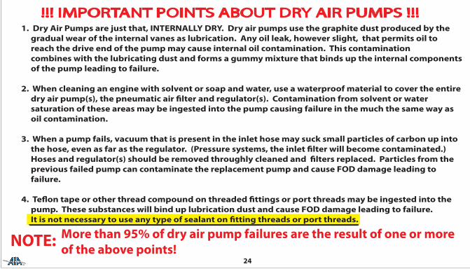
Aero Accessories, Inc.1240 Springwood Avenue Gibsonville , N.C. 27249 Tel.- 336-449-5054 800-322-3200 Fax.-336-449-5461Tempest Overhauled Dry Air Pumps are overhauled by Aero Accessories, Inc. in the USA
TM
Overhauled Dry Air Pump Warranty:Dry Air Pumps overhauled by Aero Accessories, Inc. are warranted against defects in materials and/or workmanshipfor the time periods listed below by model/series number. Aero Accessories, Inc. obligation under this warranty islimited to the repair or replacement at Aero Accessories, Inc. sole descretion any pump that upon inspection byAero Accessories, Inc is found to be defective in materials or workmanship.
211,212,215,216,3215,3216 & -9 Mods241,242 All - Models441, 442 All - Models
2 years or 1000 Hours from Time of Installation1 year or 400 Hours from Time of Installation1 year or 400 Hours from Time of Installation
TM
24
!!! IMPORTANT POINTS ABOUT DRY AIR PUMPS !!!1. Dry Air Pumps are just that, INTERNALLY DRY. Dry air pumps use the graphite dust produced by the gradual wear of the internal vanes as lubrication. Any oil leak, however slight, that permits oil to reach the drive end of the pump may cause internal oil contamination. This contamination combines with the lubricating dust and forms a gummy mixture that binds up the internal components of the pump leading to failure.
2. When cleaning an engine with solvent or soap and water, use a waterproof material to cover the entire dry air pump(s), the pneumatic air �lter and regulator(s). Contamination from solvent or water saturation of these areas may be ingested into the pump causing failure in the much the same way as oil contamination.
3. When a pump fails, vacuum that is present in the inlet hose may suck small particles of carbon up into the hose, even as far as the regulator. (Pressure systems, the inlet �lter will become contaminated.) Hoses and regulator(s) should be removed throughly cleaned and �lters replaced. Particles from the previous failed pump can contaminate the replacement pump and cause FOD damage leading to failure.
4. Te�on tape or other thread compound on threaded �ttings or port threads may be ingested into the pump. These substances will bind up lubrication dust and cause FOD damage leading to failure. It is not necessary to use any type of sealant on �tting threads or port threads.
NOTE: More than 95% of dry air pump failures are the result of one or moreof the above points!
FINAL SYSTEMS CHECK - After new pump is installed and secured, before running engine to check pneumatic system, inspectall hoses, �lters, and regulator(s) for proper installation.Run engine(s) and check operation to verify that pneumatic system is operating within aircraft speci�cations. (Refer to Aircraft Service / Maintenance Manual.)
CAUTION: WHEN INSTALLING PUMP FITTINGS, SECURE PUMP IN VISE BY DRIVE END PAD AS SHOWN IN FIG. 13. SECURING PUMP BY PUMPING CHAMBER, FIG. 14, COULD AFFECT INTERNAL CLEARANCES CAUSING PUMP FAILURE.
4. Install pump with new mounting gasket and, if required a LRT Diverter.
5. Secure pump with proper mounting hardware and tighten. (Refer to Aircraft Engine Service / Maintenance Manual for speci�ed torque requirements.)
6. Attach hose to correct �ttings, being careful not to cut the I.D. of the hoses when sliding over end of �ttings. Secure hoses with proper hardware.
23
DRY AIR PUMP INSTALLATION -1. Before installing replacement pump, con�rm it is the correct model for the application.
2. Perform maintenance check of �ttings, hoses, regulator(s) and �lters.
NOTE: If previous pump has failed prematurely, perform maintenance system check toinsure all components of the pneumatic system are functional and working correctly.
CAUTION: AIRCRAFT WITH DUAL DRY AIR PUMPS MAY LOSE REDUNDANCY FEATURE IF THEMANIFOLD / CHECK VALVE IS NOT FUNCTIONING PROPERLY.
3. With replacement pump gripped by the mounting �ange in vise (Fig. 13) install �ttings into ports �nger-tight. (Use NO Pipe Sealant or Tape on threads.) Tighten with proper wrench, no more than one (1) full turn to required position. Do Not grip pump by the sides of the pumping chamber (Fig. 14).
Figure 13 Figure 14 22
F.
G.
Vacuum Regulator -
Regulator, Valves and Deice Valves -
Regulator must be clean, oil free and in airworthy condition for proper operation. Replace regulator �lter afterinstalling new pump or every 100 hours or annually.Run engine and check for proper operation of regulator. (Refer to Aircraft Service / Maintenance Manual) adjustas necessary for correct vacuum setting for your aircraft. (TempestTM Regulators should require no �eldadjustment, contact Aero Accessories, Inc. if a TempestTM regulator gives an indication of improper operation.)
Before installing a replacement dry air pump, particularly if old pump has failed prematurely, the followingguidelines must be accomplished.1. Determine if pnuematic system problem was cause of failure. This can be accomplished using a commercially available test kit. (Contact Aero Accessories, Inc. for test kit information.)2. Test aircraft’s pneumatic system according to outlined instructions supplied with test kit and the Aircraft Service / Maintenance Manual.3. Any regulator, valve or deice valve found to be defective must be replaced in accordance with the Aircraft Service / Maintenance Manual to prevent possible premature failure of new pump after installation on aircraft.
H. Manifolds / Check Valves - Manifolds and check valves have internal rubber components that can deteriorate from age becoming hard andbrittle, and lose their sealing capacity. (Refer to Aircraft Service / Maintenance Manual for manifolds, checkvalves inspection intervals and procedures.)
21
20
D.
E.
Pump Fittings -
Hoses -
1. Inspect for damage and cleanliness.2. Bent or kinked �ttings (Figure 12) can reduce air �ow.3. Check threads for damage, replace if necessary.4. Clean �ttings inside and out to remove any loose debris.5. Install �ttings as described in Section ‘Dry Air Pump Installation’.
Remove and inspect hoses for the following conditions;1. Hard, Cracked, Brittle, or Oil Contaminated.2. Determine if liner separation has occurred inside of hose. Liner separation can restrict air �ow. (Replace hose if any one of these conditions is found.)3. If replacing a previously failed pump, throughly clean inside of hoses , making sure all loose debris have been removed before attaching hoses.
NOTE: PUMPS INTERNAL CLEARANCES WILL NOT ALLOW FOREIGN PARTICLES TO PASS THOUGHWITHOUT CAUSING DAMAGE OR FAILURE. MAKE SURE HOSES ARE CLEAN.
Figure 12
19
PNEUMATIC SYSTEM MAINTENANCE
A.
B.
C.
Oil Leaks -
Oil Seal - Inspect drive pad seal, it should be dry. If any oil is found replace the oil seal. (Refer to enginemanufacturer’s parts manual for correct seal part number and installation instructions.)RECOMENDATION: If a replacement pump is being installed on a midtime engine, replace the oil seal evenif area is dry. The oil seal could start leaking before engine TBO is reached.
Clean �lters are essential for a pneumatic system to operate properly. Dirty �lters can reduce air �ow topump causing the pump to operate at higher temperatures and increasing pump wear. Dirty �lters cana�ect operation of pneumatic instruments and regulator(s) and can cause low vacuum or low or excessive pressure.NOTE: REFER TO AIRCRAFT MAINTENANCE/SERVICE MANUAL FOR FILTER REPLACEMENT SCHEDULE.
Inspect engine and engine compartment for oil leaks that could contaminate the dry air pump or reachthe inlet �lter on pressure systems or the vacuum regulator, if located in the engine compartment.
On Cessna 150 / Continental O-200 and some other engines the pump mounts with the drive shaft vertical. Pumps designed for vertical installation such as the AA3215CC-9, AA215CC-9, or AA211CC-9 are normally required. When installing an AA3215CC-9 the open channel should face aft towards the �rewall and away from sources of oil contami-nation. On Cessna 172’s having 2 pumps on the engine, the lower pump mounts with the ports slightly rotated at about 20 degrees. The channel pointing closest to the ground should be left open.
The photographs below show the inlet and outlet ports at the 6:00 and 3:00 positions. Notice that in both picturesthe bottom channel is open and pointing towards the ground. The LRT diverter MUST be installed so that the lower drain channel of the mounting �ange remains open and pointing towards the ground.
NOTE:
Ports at 6:00 PositionLRT on TOP
Ports at 3:00 Position(from pilots view)
LRT on TOP
Leave Channel pointing towards the
ground Open.
LRT DiverterInstalled
Figure 1117
Ports at 12:00 PositionLRT on TOP
Ports at 9:00 Position(from pilot’s view)
LRT on TOPLRT DiverterInstalled
Channel Pointingtowards bottom
(ground)Leave Open
Most dry air pumps are installed with the inlet and outlet ports in the 12:00, 3:00, 6:00, or 9:00 positions.Tornado pumps have four (4) exit channels in the mounting �ange face. When a pump is installed on an aircraft the three (3) upper-most channels MUST be plugged by the LRT diverter. The bottom channel is leftopen to allow oil to drain away from the pump’s mechanical workings. In other words, the open, unpluggedchannel should be pointing towards the ground.
The photographs below and on the next page illustrate proper installation positions of the LRT diverter whenthe pump ports are at di�erent positions.
18
Figure 10
82-50130-BMounting GasketShown
LRT ShownInstalled
It is important that the LRT diverter is �rmly inserted into the upper three (3) channels in the mounting �ange face,with the middle leg of the LRT pointing UP, regardless of the pump inlet & outlet port orientation being vertical orhorizontal and that the LRT be �ush with the �ange mounting surface before installing the mounting gasket.(As shown below.) Refer to pages 17 & 18 for further ampli�cation of LRT usage.NOTE: The LRT diverter is not a mounting gasket. Either the 82-50130 or 82-50130-B mounting gasket MUST beused with the LRT diverter when installing a Tempest Dry Air Pump with the mounting �ange that has beenmachined to accept it. It is suggested that the 82-50130-B gasket be utilized in Dry Air Pump installations due toits increased sealing capability.
16
Figure 9
15
The 82-50130 gasket incorporates 8 small holes for accessories that require engine oil lubrication. The oil passageholes have been eliminated in the 82-50130-B mounting gasket. The LRT diverter is required on the AeroAccessories Dry Air Pumps New & Overhauled that have channels milled into their mounting �ange faces. Eitherthe 82-50130 or 82-50130-B gaskets can be used with the LRT diverter, however the ‘-B’ gasket is preferred due toits increased sealing capability.Refer to pages 17 & 18 for further ampli�cation on LRT usage.
LRT Diverter - Used witheither Gasket dependentupon pump �ange being
milled to accept LRT
Oil PassageHoles - Notrequired in
Dry AirPump
Installations
Standard 82-50130 Gasket 82-5013-B GasketFigure 8
14
LRT & Mounting Gasket Installation Guidelines200, AA200, AA3200, 240, AA240, 400, AA400 Series Overhauled Dry Air Pumps
Dry Air Pumps overhauled by Aero Accessories may include our patented ‘channel cut’ in the mounting �ange face.These, REQUIRE our patented LRT diverter and are designed to channel oil away from the dry air pump’s mechanicalworkings if the drive pad’s oil seal begins to leak. Pumps including the ‘channel cuts’ will also feature Fully Encloseddrive ends designed to eliminate oil and oil residues from entering the drive mechanism. Pumps without the �angeface ‘channel cut’ DO not require and MUST NOT use the LRT diverter.
LRT Diverter
Channel CutsLRT Required
Fully Enclosed Drive
NOTE: The LRT Diverter is nota substitute for a mountinggasket. Mounting gasket82-50130-B or 82-50130must be used with the LRTproperly installed.
Old Style Open Drive
NO Channel CutsNO LRT Permitted
Figure 7
13
Figure 6-1 Figure 6-3Figure 6-2New VaneIndication
Vane still Good - Land not touching
top of barrel
Indicating Bead LandTOUCHING Barrel:
Vane at Service LimitREPLACE PUMP
Pump sectinoal views - for reference only
REPLACE PUMPIF ANY VANE ISAT IT’S SERVICE
LIMIT.
12
240 & 400 Series Wear Indicating ToolP/N: 82-580122-2A6
Insert this endinto the
Inspection PortHole
Barrel
Plunger
Figure 4
Figure 5
Wear Indicating Tool installed inPump Inspection Port Hole
Plunger IndicatingBead Land
11
NOTE: Edges of rotor slot visible in inspection port holeFigure 3
442CW Shown, others similar
10
Remove Port Plug ANDStarwasher
BE SURE toREMOVE BOTHthe PLUG AND
the STARWASHERLeaving the
Starwasher inthe observation port
hole will causeerroneous
inspection resultsFigure 2
442CW Shown others similar
9
g.
h.
i.
j.
k.
If the vanes are within service limit and the pump is otherwise serviceable,clean port plug threads, install Port Plug with a NEW STAR Washer and torquePlug to 45-50 inch-pounds.
Attach the pump’s cooling shroud if removed.
Enable the ignition system, If fuel was turned o� turn it back on (assuming no other reason to leave it o�).
Attach and secure cowling.
Perform a post maintenance run-up check to verify that the vacuum / pressuresystem, as well as any other system your work may have a�ected, is workingproperly.
DO NOT substitute a di�erent screw or bolt for the plug. Use only the proper starwasher.The use of substitute parts can damage the pump.
Contact Aero Accessories, Inc. to obtain additional plugs and starwashers.WIP Plug: 82-50122-2A1Starwasher: 82-50122-2A2 or alternate AN936B-416 , MS35355-32, or MS35355-61
8
e.
f.
Insert the Vane Wear Indicator Tool , Fig 4, into the inspection port as illustrated inFig. 5. Hold the barrel securely and squarely against the pump body. With your�ngertip, gently push the plunger into the pump’s inspection port. When theplunger touches the vane, slight vane movement may be felt if the vane is not atthe bottom of its slot.
Observe the plunger’s indicating bead land position. If the indicating bead’s landis touching the barrel end, the vane is worn to the service limit. REPLACE the pumpif any vane is at it’s service limit.(Refer to Figures 6-1, 6-2, 6-3.)
NOTE: If the plunger does not slip easily into the slot, DO NOT force it.Remove the indicator tool and check for correct alignment of the rotor slot to theport. (Refer to Figure 3.)
DO NOT rotate propeller or pump’s shaft when the indicator tool probe is insertedin the inspection port. Doing so may break or chip the rotor. If the pump is turnedwith the probe in the pump, replace the pump even if you don’t think it is damaged.A cracked of chipped rotor may operate normally for a while then fail without warning.
7
Vane length measurement (Side WIP):NOTE: in most cases, measuring the vanes can be done with the pump mounted on the aircraft. However, if the inspection port hole can not be accessed with thepump mounted, remove it from the engine, turn the pump’s shaft by hand, and follow the same general instructions with respect to measuring the vanes.Reinstall the pump in accordance with instructions in the aircraft’s maintenancemanual.
“Safe The Engine”; remove the pump cooling shroud if necessary.
Insure the area around the inspection port plug is clean so that when the plugis removed nothing can fall into the pump.
Remove the Inspection Port Plug AND Star Washer, refer to Fig 2. Failure to remove the star washer will cause a false indication.
While looking into the indicator port, have an assistant slowly move thepropeller by hand in the normal direction of rotation, until a vane slot isaligned precisely in the center of the port, refer to Fig 3. If you go too far,just keep turning to the next slot.
a.
b.
c.
d.
6
Recommended Vane Wear Observation Intervals for AA240 & AA400 Series Dry Air Pumps:1st Observation - 300 hours pump time-in-service.Subsequent observations - each 100 hours time-in-service or at annual inspection, whichever comes �rst,after the initial observation.
Safety:For increased safety, it is recommended to perform the vane wear inspection during procedures thatrequire the spark plugs be removed, such as engine compression check.NEVER move the propeller on a ‘hot’ engine.ENSURE: Magnetos set to BOTH OFF. Fuel Mixture Closed. Fuel to OFF.ALWAYS remain clear of the propeller’s arc and ensure that other personnel do so.
It is the pilot’s / operator’s responsibility to determine that the entire pneumatic system is in a safe, serviceable,and airworthy condition. Use the aircraft manufacturer’s maintenance instructions and recommendations todetermine the status of the entire pneumatic system.
5
Side Wear Port Indicator Instructions 240 & 400 Series240, 400, AA240, AA400 Series Overhauled Dry Air Pumps with side WIP installedAero Accessories, Inc. has FAA approval to install its patented Side Wear Indicator Port in overhauled Airborne240 & 400 series dry air pumps as well as on Aero Accessories AA240 & AA400 series overhauled dry air pumps.Aero Accessories, Inc. recommends the 1st observation be conducted at 300 hours pump service, furtherobservations should be conducted at intervals based on position of the Wear Indicator Tool’s indicating bead.Wear Indicator Ports make it possible to identify and remove pumps from service with vanes worn beyond theirservice life. Removing such pumps BEFORE THEY FAIL reduces the risk of in-�ight failure and improves safety. In addition to using the wear indicator port, always inspect the pump in accordance with the aircraft manufacturer’srecommendations as well as for any other defects or conditions such as overheating (crinkled or burned decals),oil contamination, physical damage, looseness of parts and/or hardware, etc., that would render the pump unsuitablefor continued service.If any condition is discovered or suspected that would render the pump unsuitable for continuation in service, replace the pump, regardless of vane wear status.Pumps incorporating the side WIP should be removed from service according to vane wear observations barringany other conditions that would indicate the necessity for earlier replacement.The recommended TBO for 240, AA240, 400, or AA400 series pumps without the side WIP is 600 hours.Aero Accessories, Inc. recommended Side Wear Port procedure begins on page 6. See Aero Accessories, Inc ServiceLetter SL-007 for further information, available on www.aeroaccessories.com
Failure of an air pump may result in the loss of the pneumatically powered gyro �ight instruments and pneumaticdeice equipment. IMC equipped aircraft should have a pneumatic or electric backup source in the event of theaircarft’s primary pump fails
4
Recommended Rear WIP Vane Wear Observation Procedure1st Observation 600 hours time-in-serviceNext Observation(s) should be made as deemed necessarybased on vane wear rate observed.
1. Remove WIP Port Plug
At 600 hours pump service life performa visual observation of the wear portindicator. If the top of the vane has notentered the indicator hole, the nextobservation should be performed at1000 hours of pump service life.
At 600 hours pump service life the visualobservation reveals the backside of thevane has entered the indicator hole, thenext observation should be performedat 800 hours of pump service life.
200 SeriesRear CoverWearIndicatorPort (WIP)
When observations reveal the end of thevane to be in the middle of the indicatorhole, future observations should be performed at every one hundred (100)hours of service until the vane reachesthe bottom 1/8 of the indicator hole.
To help prevent in-�ight failure due to acritically short vane binding in a rotorslot, replace the pump when the end ofthe vane is observed in the lower 1/8 ofthe indicator hole.
200 Series Overhauled PumpsEquipped with WIP
Figure 1
2. After Observation Reinstall WIP Port Plug
3
Rear Cover Wear Indicator Port Instructions 200 & 3200 Series215CC, 215CC-9, 216CW, AA215CC, AA215CC-9, AA216CW, AA3215CC, AA3215CC-9, &AA3216CW Overhauled Dry Air PumpsAero Accessories, Inc. has FAA approval to install its patented rear cover Wear Indicator Port in overhauledAirborne 215CC and 216CW dry air pumps as well as AA215CC, AA216CW, AA3125CC, and AA3216CW overhauleddry air pumps. Removing the port plug allows for a visual observation to determine vane wear. The end of the vane closestto the center of the rotor may be viewed through the small indicator hole in the port area, refer to observationprocedure on page 4.The Rear Wear Port Indicator is a visual aid in determining vane length at recommended observation intervals.Individual �ndings while conducting observations do not constitute the actual remaining life of the pump.Components of an aircraft can and do fail at anytime without warning. During the typical service life of a pump, it’s vane length can become a critical factor in determining the remaining life of the pump. The vanelength will be reduced by normal wear to a point that it may bind in a rotor slot and break, causing pumpfailure. The Rear Wear Indicator Port is designed as an aid to help monitor vane length.
Failure of an air pump may result in the loss of the pneumatically powered gyro �ight instruments. IMCequipped aircraft should have a pneumatic or electric backup source in the event the aircraft’s primarypump fails.
For additional information refer to Aero Accessories, Inc Service Letter SL-004, available on www.aero-accessories.com
2
WARNING CAUTION ATTENTION
DO NOT:
REPAIR:
CLEAN OUT:
DO NOT:
use te�on tape or any other type of thread sealant or compound on the threaded�ttings or ports of this pump. Extremely close internal tolerances will not permitingestion of anything but clean air into this unit without failure occuring.
any oil leak, however slight, that will permit oil to reach the drive end of the pump orthe inlet �lter(s). Any oil which enters the pump, even one drop, may cause failure.
all lines and hoses, change �lters and clean regulators after failure of a dry airpump before installing the replacement dry air pump.
cut rubber hose lining on metal �tting edges while slipping hoses onto �ttings.A piece of rubber hose liner as small as a grain of sand will easily cause pump failure.
Better than 95% of all dry air pumps returned for premature failure are the results of oneof the above mentioned conditionsAero Accessories, Inc.
1240 Springwood Avenue Gibsonville, N.C. 27249 USATM
FAA Approved Overhaul
Operators Manual
InstallationInstructions
excellence
OVERHAULED 200 , 3200 , 240 , 400 Series Dry Air Pumps
TM
excellence