overflow tanks- - Wright Laboratory | Yale...
20
1 -overflow tanks- Present design status T. Wise, for Wisconsin Group AD Preliminary Design Review, July 30, 2007, IHEP
Transcript of overflow tanks- - Wright Laboratory | Yale...

1
-overflow tanks-
Present design status
T. Wise, for Wisconsin Group
AD Preliminary Design Review, July 30, 2007, IHEP
2
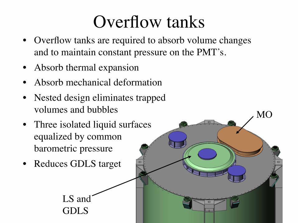
Overflow tanks• Overflow tanks are required to absorb volume changes
and to maintain constant pressure on the PMT’s.• Absorb thermal expansion• Absorb mechanical deformation• Nested design eliminates trapped
volumes and bubbles• Three isolated liquid surfaces
equalized by common barometric pressure
• Reduces GDLS target
LS and GDLS
MO

3
Scintillator Overflow volume requirement 150-200Liter
4 meter dia. sphere with 4mm slice has 25 liter volume
4mm
Thermal: estimate about 20 liter/degree C for scintillator
If acrylic bottom follows the curvature of the ss tank we expect a maximum of 3mm deflection from immersion in water tank.
Mechanical distortion of acrylic bottom: estimate < 25 liter.
4
Open issue: Temperatures in Hall 5, Tunnel, and water pool need to be defined.
The present overflow design can accommodate a 5 degree C difference among the three environments
5
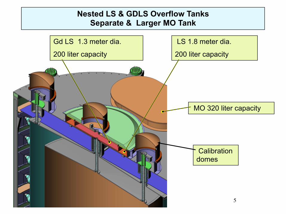
Nested LS & GDLS Overflow TanksSeparate & Larger MO Tank
Gd LS 1.3 meter dia.
200 liter capacity
LS 1.8 meter dia.
200 liter capacity
Calibration domes
MO 320 liter capacity

6
Overflow Tanks (cont.)
Gd LS Level
LS Level
5meter Lid
Overflow Lid ribs
Calibration box mounting flange
Level meter “houses”
Qty 5: 2US, 2 China, 1 emergency shut off30 cm height
limit line
LS
5 meter Lid ribs
Atmospheric pressure N2

7
Overflow Level Measurement
• Accuracy of ±1mm out of 200mm maximum• Long term contact with LS & GDLS• Compact assemblyWisconsin is testing a pressure gage to determine liquid column height.
170 mm
Sensitivity of ±1mm is more than required but it will help us see trends before they become problems, i.e. evaporation of GDLS or some types of leaks
Siemens P300 pressure gage
We need the “gage” version not the “absolute” version

8
Lifting Fixture ClearanceIHEP is designing a lifting fixture to aid in lifting the AD. The fixture should be designed to clear any attachments up to 30 cm above the lid.

9
Three Penetrations into LS & GDLS Volumes
One central, two outer

10
We have concern that the fasteners may be difficult to access and complete. A practice assembly exercise with prototype AV’s is planned.
Teflon bellows will be a custom manufacture.
Central overflow tank connection
Outer GDLS connection
Teflon Bellows Connections between Calibration Domes and Acrylic Vessels
Baseline configurations shown here.
N2

11
Bellows attach directly to 3m and 4m lids. No acrylic tubing is necessary
Central overflow tank connection

12
Flanges with threaded holes bonded to acrylic top plates
Lower attachment designs
O-ring seal with split ring clamp plate

13
LS
LS G D
L S
Upper attachment designs

14
Special details related to the outer GDLS calibration penetration
Support spool volume is not used for liquids. Filled with dry N2
GDLS is sealed by gate valve at same height as the other two gate valves.
Assembly sequence is workable if we are careful. See next slides
N2

15
1) Attach inner bellows to top of 3 meter acrylic
2) Attach outer bellows to lid of 4 meter acrylic
3) Lower 4 meter lid while threading inner bellows through hole
4) Connect top of bellows to intermediate bellows top plate (this is the difficult step!)
5) Lower SS lid and fasten intermediate top plate to custom acrylic spool
6) Attach valve
7) Fix LS vent fitting

16
Step 4: make top bellows assemblyPotential gas pocket
CL

17
Step 7: Fasten LS vent fitting
LS
GDLSMO

18
Our sample
1mm wall
49mm ID, 60mm OD
Corrugation length 375mm
Spring constant 54 Nt/cm
Teflon Bellows Information
Flared cuffs are available

19
• Open issues: Outer GDLS penetrations may have interference with SS tank rib design
• Need definite limits to
Outer GDLS calibration dome
These two features might not be compatible

20
Overflow R&D topics• Build acrylic lined nested overflow prototype
• Stability of P300 level sensors, minimize exposure to SS
• Teflon bellows O-ring seals with flared cuffs
• Realistic penetration assembly test with mock-up geometry
• Make connection of prototype calibration system to prototype overflow tanks
• All acrylic fasteners and split flanges
• Overflow materials in contact with scintillator• SS (possibly vapor only)• Teflon• Acrylic• Viton• Gate valve (vapor only)• …