OVERCURRENT PROTECTION COORDINATION CASE STUDY: …...AHMED HATIM ABDELBARI ELNIEMA AHMED OMER...
132
OVERCURRENT PROTECTION COORDINATION CASE STUDY: BALEELA OIL-FIELD NETWORK By AHMED HATIM ABDELBARI ELNIEMA AHMED OMER MOHAMED BABIKER MOHAMED ALI MOHAMED IBRAHIM Supervisor Dr. Kamal Ramadan A REPORT SUBMITTED TO University Of Khartoum In partial fulfillment for the degree of B.Sc. (HONS) Electrical and Electronics Engineering (POWER ENGINEERING) Faculty of Engineering Department of Electrical and Electronics Engineering October 2017
Transcript of OVERCURRENT PROTECTION COORDINATION CASE STUDY: …...AHMED HATIM ABDELBARI ELNIEMA AHMED OMER...

OVERCURRENT PROTECTION COORDINATION
CASE STUDY: BALEELA OIL-FIELD NETWORK
By
AHMED HATIM ABDELBARI ELNIEMA
AHMED OMER MOHAMED BABIKER
MOHAMED ALI MOHAMED IBRAHIM
Supervisor
Dr. Kamal Ramadan
A REPORT SUBMITTED TO
University Of Khartoum
In partial fulfillment for the degree of
B.Sc. (HONS) Electrical and Electronics Engineering
(POWER ENGINEERING)
Faculty of Engineering
Department of Electrical and Electronics Engineering
October 2017

ii | P a g e
DECLARATION OF ORGINALITY
I declare this report entitled “OVERCURRENT PROTECTION COORDINATION
CASE STUDY: BALEELA OIL-FIELD NETWORK” is my own work except as cited in
references. The report has been not accepted for any degree and it is not being submitted
currently in candidature for any degree or other reward.
Signature: ____________________
Name: _______________________
Date: ________________________

iii | P a g e
Acknowledgement
All the thanks, praises and glorifying is due to Almighty ALLAH.
To my mother and father, who grew me up, fed me and guided me through life.
I owe my deepest gratitude to my advisor Dr.Kamal Ramadan. First for accepting me as a
student, then for the support and help he has given me throughout the project.
Special thanks to my project partners for their hard work, support and cooperation. Besides, I
also want to thank Eng Abdallah Abdelmonem, and Eng Babikir Elnouman for their
significant assistance and help.
Many thanks to my colleagues and all the staff at the Department of Electrical and
Electronics Engineering for the pleasant working atmosphere and your friendship.

iv | P a g e
Abstract
Continuous and reliable power supply is the main goal and target for power system networks.
In this regard, many methods have been developed to enhance the performance of power
supply systems.
The present research is initiated to investigate Baleela power network, because this network
is faced by blackouts several times per year during last couple of years, this led to severe lack
of production during blackout times beside the maintenance and operation cost impact.
Using ETAP software as analysis tool, the network was drawn. The data for each component
in the network was collected from a site visit to Baleela. After running the simulator,
different fault scenarios were created to examine the existing protection system schemes and
different miss-operations results were obtained as a response of protection system to the
abnormal conditions. After studying this network, it is noticed that one of the main reasons
for blackouts is the relay setting miss-coordination caused by the use of only (DMT)
characteristics.
An optimum characteristic (IDMT) for the relays was chosen, and a completely new
coordination scheme is designed which starts first by coordinating the phase over-current
elements, for different paths from furthest downstream up to the generators. Next the earth
fault relays are coordinated for the same paths and finally the instantaneous element as a
backup protection was applied successfully.
The new relay setting coordination has been applied to all relays in the five main substations
as a result from this study. The sequence of operation is well improved and as a result the
total blackouts frequency is significantly decreased. Valuable recommendations were
suggested.
v | P a g e
المستخلص
لذلن تم إبتكار أنظمة وطرق , يعتبر إمداد الطالة بشكل مستمر وموثوق أحد أهم أهداف شبكات إمداد الطاله الكهربائية
. من أجل تحسن أداء هذه الشبكات ألمداد الطالة بالصورة المطلوبة
تم إختيار هذه الشبكة بالتحديد نسبة لتكرر اإلنمطاع التام للتيار , تم عمل هذا البحث لدراسة الشبكة الكهربائية لحمل بليلة
وذلن لألعوام المليلة الماضية مما أثر سلبا على اإلنتاج في الحمول بجانب تأثير التكاليف , الكهربائي خالل العام الواحد
. الحالية للصيانة وإعادة التشغيل
تم رسم وتمثيل شبكة بليلــــة ثم جمع البيانات الخاصة لجميع , كأداة للدراسة والتحليل(ETAP) بزَبيــج بإستخدام
(. ETAP)ثم تم إدخال هذه البيانات في برنامج المحاكاة , عناصر الشبكة عن طريك زيـــارة المولع
تى إختببر أَظًة انحًبية انحبنية انخبصة بشبكة بهـــــيهة ػٍ طزيق ػًم سيُبريىهبت ألػطبل كهزببئية فتى انحصىل ػهى
بؼذ دراسة وتحهيم انشبكة نىحظ أٌ أحذ أسببة إَقطبع إيذاد , بؼض اإلستجبببت انخبطئة يٍ َظبو انحًبية نهذِ األػطبل
(. DMT)انكهزببء هى فقذاٌ تُسيق وضبط يزحالت انحًبية َتيجة إلستخذاو طزيقة
هذا النظام , ثم ُصمم نظام تنسيك جديد للمرحالت, المناسبة لمرحالت الحماية (IDMT)كبذيم نهطزيقة انسببقة تى إختيبر
يبدأ بتنسيك عناصر مرالبة التيار في الطور الواحد وذلن لعدة مسارات في الشبكة إبتداًء من أبعد نمطة في الشبكة وصوالً
. إلى المولدت وذلن كمرحلة أولى
وأخيراً تم , في المرحلة الثانية تم تنسيك مرحالت حمياة األعطال للخطأ األرضي وذلن لنفس المسارات السابمة للشبكة
. تنسيك العناصر اللحظية كعناصر إحتياطية للحماية
. انسببق نجًيغ يزحالت انحًبية في انخًس يحطبت في انشبكة كُتيجة نهذراسة انسببقة (IDMT)تم تطبيك نظام
كنتيجة لذالن إنخفضت مرات إنمطاع اإلمداد الكهربائي , عمل المرحالت لد تحسن بصورة كبيرةنىحظ أٌ تسهسم
. بصورة ملحوظة
.تم إلتراح توصيات مهمة في آخر البحث

vi | P a g e
Table of Contents
DECLARATION OF ORGINALITY ................................................................................ ii
Acknowledgement ............................................................................................................. iii
Abstract .............................................................................................................................. iv
v.................................................................................................................................المستخلص
Table of Contents ............................................................................................................... vi
List of Figures .................................................................................................................... xi
List of Tables ................................................................................................................... xiii
CHAPTER ONE ................................................................................................................. 1
Introduction ................................................................................................................. 1
1.1 Overview .................................................................................................................... 1
1.2 Problem Statement ..................................................................................................... 1
1.3 Project background ..................................................................................................... 1
1.4 Objectives ................................................................................................................... 2
1.5 Thesis outline ............................................................................................................. 2
CHAPTER TWO ................................................................................................................ 3
2 Literature Review........................................................................................................ 3
2.1 Introduction ................................................................................................................ 3
2.2 Overview of electrical faults .................................................................................... 4
2.3 Protection Definitions ................................................................................................ 6
2.3.1 Protection System ............................................................................................... 6
2.3.2 Protection Equipment.......................................................................................... 6
2.3.3 Protection Scheme .......................................................................................... 6
2.4 Protection quality ....................................................................................................... 7
2.4.1 Overview ............................................................................................................. 7
2.5 Basic requirements of protection................................................................................ 8
2.5.1 Unit Protection (selectivity) ................................................................................ 8
2.5.2 Stability ............................................................................................................. 11
2.5.3 Reliability .......................................................................................................... 11
2.5.4 Speed of operation ............................................................................................ 11

vii | P a g e
2.5.5 Sensitivity ......................................................................................................... 11
2.6 Protection components ............................................................................................. 11
2.6.1 Voltage transformers ......................................................................................... 11
2.6.2 Current transformers ......................................................................................... 12
2.6.3 Fuses ................................................................................................................. 12
2.6.4 Relays ................................................................................................................ 13
2.6.4.1 Electromechanical Relays .......................................................................... 13
2.6.4.2 Static Relays .............................................................................................. 14
2.6.4.3 Digital Relays ........................................................................................... 14
2.6.4.4 Numerical Relays ...................................................................................... 14
2.6.5 Circuit breakers ................................................................................................. 15
2.6.5.1 Purpose of circuit breakers ........................................................................ 15
2.6.5.2 Types of Circuit Breakers .......................................................................... 16
2.7 Over-current Protection ............................................................................................ 19
2.7.1 Co-ordination Procedure ................................................................................... 19
2.7.2 Principles of Time/Current Grading ................................................................. 19
2.7.2.1 Discrimination by Time ............................................................................. 20
2.7.2.2 Discrimination by Current ......................................................................... 20
2.7.2.3 Discrimination by both Time and Current ................................................. 20
2.7.3 Standard I.D.M.T. Overcurrent Relays ............................................................. 21
2.7.4 Combined IDMT and High Instantaneous Over-current Relays ................... 21
2.8 Generator protection ................................................................................................. 21
2.9 Feeder protection ...................................................................................................... 22
2.10 Transformer protection ............................................................................................. 22
2.11 Bus-bar protection .................................................................................................... 22
2.12 Primary and Back-up Protection .............................................................................. 23
2.13 Trip Circuit Supervision ........................................................................................... 24
CHAPTER THREE .......................................................................................................... 25
Case Study: Baleela Oil-Field Network ................................................ ............ 25
3.1 Introduction ................................................................................................................. 25
3.2 Overview .................................................................................................................. 25
3.3 Baleela oil-field network description ....................................................................... 26
3.3.1 CPF station ........................................................................................................ 26
3.3.2 KEYI Substation ............................................................................................... 27

viii | P a g e
3.3.3 FNE Substation ................................................................................................. 27
3.3.4 Moga Substation ............................................................................................... 28
3.3.5 JAKE Substation ............................................................................................... 28
3.4 Network Implementation and Simulation ................................................................ 29
3.5 Simulation Scenarios (Old settings) ......................................................................... 30
3.5.1 Overview ........................................................................................................... 30
3.5.2 Three-Phase Fault Scenarios (phase) ................................................................ 30
3.5.2.1 A three phase fault on JAKE 11kV feeder ................................................ 30
3.5.2.2 A three phase fault at the transmission line ............................................... 32
3.5.2.3 A three phase fault at CPF 33kV bus-bar .................................................. 33
3.5.3 Line-To-Ground Fault Scenarios (earth fault) .................................................. 35
3.5.3.1 Line -To-Ground fault on KEYI 11kV feeder (feeder TR-6802) .............. 35
3.5.3.2 Line -To-Ground fault at transmission line between CPF and KEYI ....... 36
3.6 Concept of DMT and I.D.M.T ................................................................................. 37
3.6.1 Definite Time Relay .......................................................................................... 37
3.6.2 Inverse Time Relays ......................................................................................... 38
CHAPTER FOUR ............................................................................................................. 40
Implementation and Results ...................................................................................... 40
4.1 Introduction .............................................................................................................. 40
4.2 Analysis Conditions ................................................................................................. 40
4.3 Protection Settings Coordination Results ................................................................. 40
4.4 New Relay Settings Coordination ............................................................................ 41
4.4.1 Over-current Settings ........................................................................................ 41
4.4.1.1 JAKE –MOGA .......................................................................................... 41
4.4.1.2 MOGA – CPF ............................................................................................ 42
4.4.1.3 FNE - CPF ................................................................................................ 43
4.4.1.4 KEYI - CPF ............................................................................................... 44
4.4.2 Earth Fault Settings ........................................................................................... 45
4.4.2.1 Settings for JAKE up to the secondary of its transformer ......................... 45
4.4.2.2 Settings from JAKE primary of the transformer up to CPF ...................... 46
4.4.2.3 Settings for MOGA up to the secondary of its transformer ..................... 47
4.4.2.4 Settings from MOGA primary of the transformer up to CPF .................... 48
4.4.2.5 Settings for FNE up to Secondary of its transformer ................................ 49
4.4.2.6 Settings from FNE primary of the transformer up to CPF ........................ 50

ix | P a g e
4.4.2.7 Settings for KEYI up to secondary of its transformer ............................... 51
4.4.2.8 Settings from KEYI primary of the transformer up to CPF ...................... 52
4.4.2.9 Settings from CPF primary of its transformer up to 11kV bus section ... 53
4.5 Simulation Scenarios (new settings) ........................................................................ 54
4.5.1 Overview ........................................................................................................... 54
4.5.2 Three-Phase Fault Scenarios ............................................................................. 54
4.5.2.1 A three phase fault on JAKE 11kV feeder ................................................ 54
4.5.2.2 A three phase fault at the transmission line ............................................... 55
4.5.2.3 A three phase fault at CPF 33kV bus-bar .................................................. 57
4.5.3 Line-To-Ground Fault Scenarios (earth fault) .................................................. 58
4.5.3.1 Line -To-Ground fault on KEYI 11kV feeder (feeder TR-6802) .............. 58
4.5.3.2 Line -To-Ground fault at transmission line between CPF and KEYI ....... 61
4.6 Summery .................................................................................................................. 63
CHAPTER FIVE .............................................................................................................. 65
Conclusion ................................................................................................................ 65
5.1 Protection Settings Coordination ............................................................................. 65
5.2 Objectives Achieved ................................................................................................ 65
5.3 Recommendations .................................................................................................... 66
References ......................................................................................................................... 67
Appendix A ....................................................................................................................... 68
A.1 Transformer Data ........................................................................................................ 68
A.2 X/R Ratio for each transformer ................................................................................... 69
A.3 Transmission Lines Data .............................................................................................. 69
A.4 The generators dynamic data ....................................................................................... 70
Appendix B ....................................................................................................................... 71
OLD SETTINGS ...................................................................................................... 71
B.1 OLD SETTINGS – FNE SUBSTATION .................................................................... 71
B.2 OLD SETTINGS – MOGASUBSTATION ................................................................. 75
B.3 OLD SETTINGS – JAKE SUBSTATION ................................................................ 80
B.4 OLD SETTINGS – KEYI SUBSTATION .................................................................. 85
B.5 OLD SETTINGS – CPF SUBSTATION .................................................................... 90
Appendix C ....................................................................................................................... 97

x | P a g e
NEW SETTING ........................................................................................................ 97
C.1 NEW RELAY COORDINATION SETTINGS – FNE SUBSTATION ...................... 97
C.2 NEW RELAY COORDINATION SETTINGS – JAKE SUBSTATION.................. 101
C.3 NEW SETTINGS – KEYI SUBSTATION ................................................................ 105
C.4 NEW RELAY COORDINATION SETTINGS – MOGA SUBSTATION ............... 109
C.5 NEW RELAY COORDINATION SETTINGS – CPF STATION ............................ 113

xi | P a g e
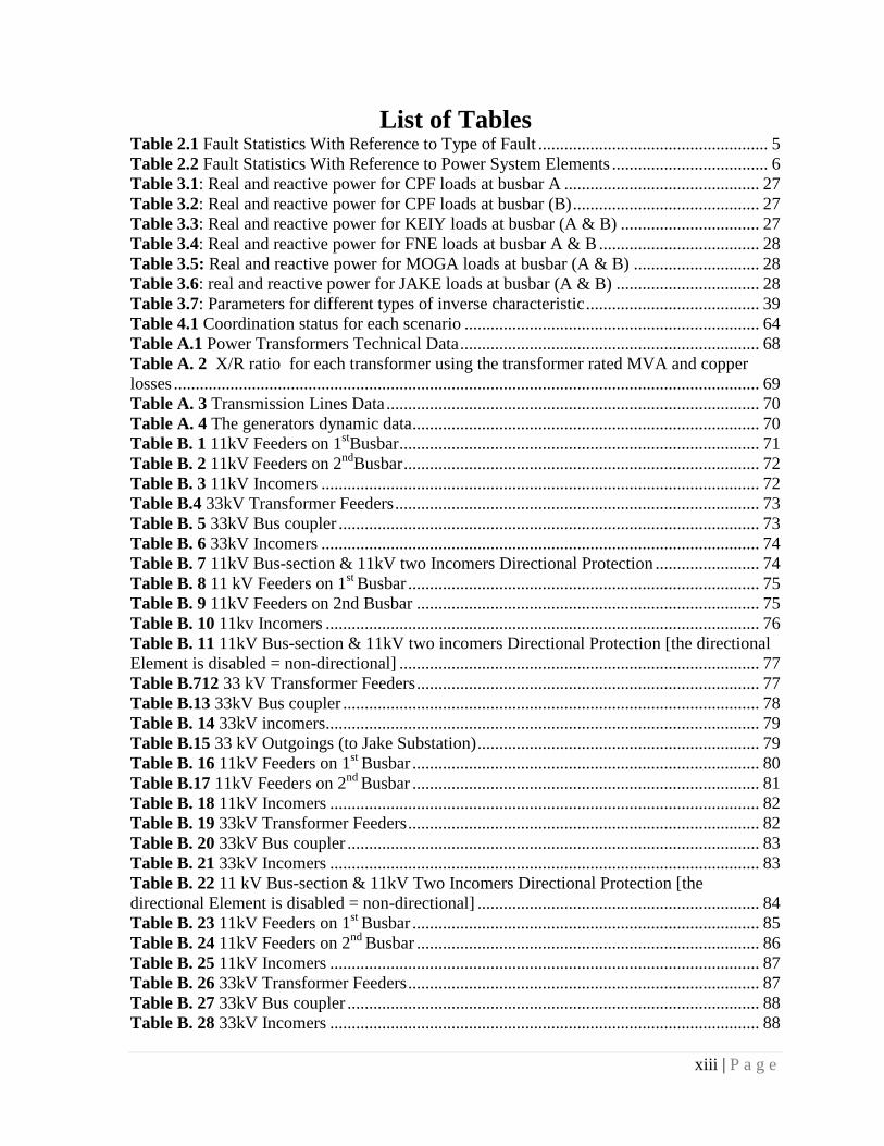
List of Figures
Figure 2.1 Types of faults on a three-phase system: (A) Phase-to-earth fault; (B) Phase-to-
phase fault; (C) Phase-to phase- to-earth fault; (D) Three-phase fault; (E) Three-phase-to-
earth fault .............................................................................................................................5 Figure 2.2 Zones of protection............................................................................................ 7 Figure 2.3 Overlapping of zones ........................................................................................ 8
Figure 2.4 Application of principle of grading.................................................................. 10 Figure 2.5 Over current time grading ................................................................................ 10 Figure 2.6 Arc control circuit-breaker ............................................................................... 16
Figure 2.7 Oil circuit-breaker ............................................................................................ 17 Figure 2.8 Air break switchgear ......................................................................................... 18 Figure 3.1 Geographic description of BALEELA network ............................................... 26 Figure 3.2 Baleela Oil-Field Network Single Line Diagram ............................................ 29
Figure 3.3 Three phase fault on JAKE (CH05 TR7802A) feeder ..................................... 30 Figure 3.4 sequence of operation for JAKE 11kV feeder ................................................. 31
Figure 3.5 Three phase fault at MOGA-JAKE transmission line ..................................... 32 Figure 3.6 sequence of operation for fault at MOGA-JAKE transmission line ................ 32
Figure 3.7 Three phase fault at CPF 33kV bus-bar (B) ..................................................... 33 Figure 3.8 sequence of operation for a fault on CPF 33kV bus-bar (B) ........................... 34 Figure 3.9 Line-to-Ground fault on KEYI 11kV feeder ................................................... 35
Figure 3.10 The sequence of operation for Line-to-Ground fault on KEYI 11kV feeder .. 35
Figure 3.11 Line -To-Ground fault at transmission line between CPF and KEYI ............ 36 Figure 3.12 Sequence of operation for Line-to-Ground fault at CPF-KEYI transmission
line .......................................................................................................................36
Figure 3.13 Definite time relay curve ................................................................................ 38 Figure 3.14 Inverse time relay curve ................................................................................. 38 Figure 4.1 The new phase [O/C] settings for JAKE-MOGA path relays ......................... 41
Figure 4.2 The new phase [O/C] settings for MOGA-CPF path relays ........................... 42 Figure 4.3 The new phase [O/C] settings for FNE-CPF path relays ............................... 43
Figure 4.4 The new phase [O/C] settings for KEYI-CPF path relays .............................. 44
Figure 4.5 New earth fault settings for JAKE up to the secondary of its transformer .... 45
Figure 4.6 New earth fault settings from JAKE primary of the transformer up to CPF . 46
Figure 4.7 New earth fault settings For MOGA up to secondary of its transformer ...... 47 Figure 4.8 New earth fault settings from MOGA primary of the transformer up to CPF
...........................................................................................................................48 Figure 4.9 New earth fault settings for FNE up to secondary of its transformer ........... 49 Figure 4.10 New earth fault settings from FNE primary of the transformer up to CPF ... 50
Figure 4.11 New earth fault settings from KEYI up to secondary of its transformer ...... 51 Figure 4.12 New earth fault settings from KEYI primary of the transformer up to CPF . 52 Figure 4.13 New earth fault settings for CPF primary of its transformer up to 11kV bus
section .......................................................................................................................53 Figure 4.14 Three phase fault on JAKE 11kV (CH05 TR7802A) feeder ........................ 54
Figure 4.15 sequence of operation for a three phase fault on JAKE 11kV feeder ........... 55 Figure 4.16 Three phase fault at MOGA-JAKE transmission line ................................... 56
Figure 4.17 sequence of operation for a three phase fault at MOGA-JAKE line ............ 56

xii | P a g e
Figure 4.18 Three phase fault at CPF 33kV bus-bar (B) .................................................. 57 Figure 4.19 sequence of operation for three phase fault at CPF 33kV bus-bar (B) ......... 58 Figure 4.20 Line-to-Ground fault on KEYI 11kV feeder ................................................. 59 Figure 4.21 The sequence of operation for Line-to-Ground fault on KEYI 11kV feeder 60
Figure 4.22 Line -To-Ground fault at transmission line between CPF and KEYI ........... 61 Figure 4.23 sequence of operation for Line-to-Ground fault on CPF- KEYI transmission
line .......................................................................................................................62
xiii | P a g e
List of Tables Table 2.1 Fault Statistics With Reference to Type of Fault ..................................................... 5 Table 2.2 Fault Statistics With Reference to Power System Elements .................................... 6 Table 3.1: Real and reactive power for CPF loads at busbar A ............................................. 27 Table 3.2: Real and reactive power for CPF loads at busbar (B) ........................................... 27 Table 3.3: Real and reactive power for KEIY loads at busbar (A & B) ................................ 27
Table 3.4: Real and reactive power for FNE loads at busbar A & B ..................................... 28 Table 3.5: Real and reactive power for MOGA loads at busbar (A & B) ............................. 28 Table 3.6: real and reactive power for JAKE loads at busbar (A & B) ................................. 28 Table 3.7: Parameters for different types of inverse characteristic ........................................ 39
Table 4.1 Coordination status for each scenario .................................................................... 64 Table A.1 Power Transformers Technical Data ..................................................................... 68 Table A. 2 X/R ratio for each transformer using the transformer rated MVA and copper
losses ....................................................................................................................................... 69 Table A. 3 Transmission Lines Data ...................................................................................... 70 Table A. 4 The generators dynamic data ................................................................................ 70 Table B. 1 11kV Feeders on 1
stBusbar ................................................................................... 71
Table B. 2 11kV Feeders on 2nd
Busbar .................................................................................. 72 Table B. 3 11kV Incomers ..................................................................................................... 72
Table B.4 33kV Transformer Feeders .................................................................................... 73 Table B. 5 33kV Bus coupler ................................................................................................. 73
Table B. 6 33kV Incomers ..................................................................................................... 74 Table B. 7 11kV Bus-section & 11kV two Incomers Directional Protection ........................ 74 Table B. 8 11 kV Feeders on 1
st Busbar ................................................................................. 75
Table B. 9 11kV Feeders on 2nd Busbar ............................................................................... 75 Table B. 10 11kv Incomers .................................................................................................... 76
Table B. 11 11kV Bus-section & 11kV two incomers Directional Protection [the directional
Element is disabled = non-directional] ................................................................................... 77 Table B.712 33 kV Transformer Feeders ............................................................................... 77
Table B.13 33kV Bus coupler ................................................................................................ 78 Table B. 14 33kV incomers.................................................................................................... 79
Table B.15 33 kV Outgoings (to Jake Substation) ................................................................. 79
Table B. 16 11kV Feeders on 1st
Busbar ................................................................................ 80
Table B.17 11kV Feeders on 2nd
Busbar ................................................................................ 81 Table B. 18 11kV Incomers ................................................................................................... 82 Table B. 19 33kV Transformer Feeders ................................................................................. 82 Table B. 20 33kV Bus coupler ............................................................................................... 83 Table B. 21 33kV Incomers ................................................................................................... 83
Table B. 22 11 kV Bus-section & 11kV Two Incomers Directional Protection [the
directional Element is disabled = non-directional] ................................................................. 84 Table B. 23 11kV Feeders on 1
st Busbar ................................................................................ 85
Table B. 24 11kV Feeders on 2nd
Busbar ............................................................................... 86
Table B. 25 11kV Incomers ................................................................................................... 87
Table B. 26 33kV Transformer Feeders ................................................................................. 87 Table B. 27 33kV Bus coupler ............................................................................................... 88 Table B. 28 33kV Incomers ................................................................................................... 88

xiv | P a g e
Table B. 29 11kV Bus-section & 11kV Two Incomers Directional Protection [the directional
Element is disabled = non-directional] ................................................................................... 89 Table B. 30 11kV Substation Feeders ................................................................................... 90 Table B. 31 11Kv Substation New Added Feeders ............................................................... 92
Table B. 32 11 kV Bus-section & 11 kV Transformer feeders .............................................. 94 Table B. 33 33 kV Transformer Feeders ................................................................................ 94 Table B. 34 11 kV Bus-section & 11 kV Transformer feeders .............................................. 95 Table B. 35 33 kV Transformer Feeders ................................................................................ 95 Table B. 36 33kVBustie ......................................................................................................... 96
Table B. 37 33 kV outgoings ................................................................................................. 96 Table C.1 11kV FEEDERS on 1
st Busbar.............................................................................. 97
Table C.2 11kV FEEDERS on 2nd
Busbar ............................................................................. 98 Table C.3 11kV incomers ...................................................................................................... 98 Table C.4 33kV Transformer Feeders.................................................................................... 99 Table C.5 33kV Bus coupler .................................................................................................. 99
Table C.6 33kV incomers ...................................................................................................... 99 Table C.7 11kV Bus-section & 11kV two incomers Directional Protection ....................... 100
Table C. 8 11kV FEEDERS on 1st Busbar .......................................................................... 101 Table C. 9 11kV FEEDERS on 2nd Busbar ........................................................................ 102 Table C.10 11kV incomers .................................................................................................. 103
Table C.11 33kV Transformer Feeders................................................................................ 103
Table C. 12 33kV Bus coupler ............................................................................................. 104 Table C. 13 33kV Incomers ................................................................................................. 104 Table C.14 11kV Bus-section & 11kV two incomers Directional Protection ..................... 104
Table C. 15 11kV FEEDERS on 1st Busbar ........................................................................ 105 Table C.16 11kV FEEDERS on 2nd Busbar ....................................................................... 106
Table C.17 11kV Incomers .................................................................................................. 106 table C. 18 33kV Transformer Feeders ................................................................................ 107 Table C. 19 33kV Bus coupler ............................................................................................. 107
Table C.20 33kV Incomers .................................................................................................. 107 Table C.21 11kV Bus-section & 11 kV two incomers Directional Protection .................... 108
Table C.22 11kV FEEDERS on 1st Busbar ........................................................................ 109
Table C.23 11kV FEEDERS on 2nd Busbar ....................................................................... 110 Table C. 24 11kV Incomers ................................................................................................. 110 Table C. 25 33kV Transformer Feeders............................................................................... 111
Table C.26 33kV Bus coupler .............................................................................................. 111 Table C. 27 11kV Bus-section & 11kV two incomers Directional Protection [the directional
Element is disabled = non-directional] ................................................................................. 112 Table C.28 NEW 11KV SUBSTATION FEEDERS .......................................................... 114 Table C.29 11kV Bus-section & 11kV Transformer feeders ............................................... 116
Table C.30 33kV Transformer Feeders................................................................................ 116 Table C.31 33kV outgoings ................................................................................................. 117

xv | P a g e
List of ABBREVIATIONS
IEEE Institute of Electrical and Electronic Engineering
SLD Single Line Diagram
KVA Kilo Volt Ampere
KW Kilo Watt
KV Kilo Volt
DMT Definite Minimum Time
IDMT Inverse Definite Minimum Time
OC Over Current
CT Current Transformer
VT Voltage Transformer
CB Circuit Breaker
IEC International Electro-technical Commission
SI Standard Inverse
VI Very Inverse
ETAP Electrical Transient Analysis Program
TMS Time Multiplier Setting
OHTL Over Head Transmission Line
MVA Mega Volt Ampere
MW Mega Watt

Chapter 1 [Introduction]
1 | P a g e
CHAPTER ONE
1 Introduction
1.1 Overview
This chapter is intended to give the reader an idea about the project‟s problem, background,
objectives. In addition, an overview of the report layout is given.
1.2 Problem Statement
In Sudan , Oil and Gas operating companies have its own power network containing
generation, transmission, distribution, protection, etc. systems. One of the most challenges
facing these companies is the power protection systems, because the production fields
located at areas countered unstable security situations, for example local people normally
cutting power cables, transmission lines earth wires, steel bars, etc., another frequent
problems are the lightning strikes hitting the OHTL during rainy seasons as a result of that
power disturbance is frequently take place.[5]
1.3 Project background
The protection for an electrical system should not only be safe under all service conditions
but, to ensure continuity of service, it should be selectively coordinated as well. A
coordinated system is one in which only the faulted circuit is isolated without disturbing any
other part of the system.
Over current protection devices should also provide short-circuit as well as overload
protection for system components, such as bus, cables, motor controllers, ...etc.
To obtain reliable, coordinated operation and assure that system components are
protected from damage, it is necessary to first calculate the available fault current at various
critical points in the electrical system. Once the fault levels are determined, the

Chapter 1 [Introduction]
2 | P a g e
electrical design professional can specify proper interrupting rating requirements, selectively
coordinate the system, and provide component protection.[6]
1.4 Objectives
The objectives of the project can be summarized as follows:
Simulate Baleela Oil-Field power Network using ETAP software.
Analyze Baleela Oil-Field power Network from the protection point of view
Point out the disadvantages of the currently used relay settings at Baleela power
Network.
Perform over-current phase (O/C) and earth fault protections on this network and
obtain its relays settings and co-ordination.
Apply instantaneous protection as a back-up protection.
1.5 Thesis Layout
Chapter two gives a detailed discussion of all the concepts and theories which are used in
protection co-ordination analysis.
Chapter three Baleela oil-field power network had been taken as case study, detailed
description about the system and different faults scenarios on the network had been
conducted.
Chapter four explains how to change the protection philosophy by using the more flexible
IDMT principle for over-current and earth fault. Different scenarios of faults on this network
had been conducted to assure that the protection scheme is operating adequately.
Chapter five provides conclusion of results, discussion and recommendations.
Appendix A presents the electrical system data for all substations.
Appendix B contains the old protection relay settings as recorded directly from the
instruments interface.
Appendix C contains the new relay coordination settings for each substation.

Chapter 2 [LITERATURE REVIEW]
3 | P a g e
CHAPTER TWO
2 Literature Review
2.1 Introduction
An electric power system is a network deployed to supply, transfer, and use electric power
with both reliability and economy .A power system is not only capable to meet the present
load but also has the flexibility to meet the future demands on a continuous basis.[1]
To ensure the maximum return on the large investment in the equipment, which goes to make
up the power system and to keep the users satisfied with reliable service, the whole system
must be kept in operation continuously without major breakdowns . This can be achieved in
two ways :
The first way is to implement a system adopting components, which should not fail and
requires the least or nil maintenance to maintain the continuity of service. By common
sense, implementing such a system is neither economical nor feasible, except for small
systems.
The second option is to foresee any possible effects or failures that may cause long-term
shutdown of a system.
The main idea is to restrict the disturbances during such failures to a limited area and
continue power distribution in the balance areas. Special equipment is normally installed to
detect such kind of failures (also called „faults‟) that can possibly happen in various sections
of a system, and to isolate faulty sections so that the interruption is limited to a localized area
in the total system covering various areas. The special equipment adopted to detect such
possible faults is referred to as „protective equipment or protective relay‟ and the system that
uses such equipment is termed as „protection system‟.[2]
Chapter 2 [LITERATURE REVIEW]
4 | P a g e
A protective relay is the device, which gives instruction to disconnect a faulty part of the
system. This action ensures that the remaining system is still fed with power, and protects the
system from further damage due to the fault. Hence, use of protective apparatus is very
necessary in the electrical systems, which are expected to generate, transmit and distribute
power with least interruptions and restoration time. It can be well recognized that use of
protective equipment are very vital to minimize the effects of faults, which otherwise can kill
the whole system.[1]
2.2 Overview of electrical faults
Electrical faults usually occur due to breakdown of the insulating media between live
conductors or between a live conductor and earth. This breakdown may be caused by anyone
or more of several factors for example mechanical damage, overheating, voltage surges
(caused by lightning or switching), ingress of a conducting medium, ionization of air, or
misuse of equipment.
Fault currents release an enormous amount of thermal energy, and if not cleared quickly may
cause fire hazards, extensive damage to equipment and risk to human life. Faults are
classified into two major groups: symmetrical and unbalanced (asymmetrical).Symmetrical
faults involve all three phases and cause extremely severe fault currents and system
disturbances. Unbalanced faults include phase-to-phase, phase-to-ground, and phase-to-
phase-to-ground faults. They are not as severe as symmetrical faults because not all three
phases are involved. The least severe fault condition is a single phase-to-ground fault with
the transformer neutral earthed through a resistor or reactor. However, if not cleared quickly,
unbalanced faults will usually develop into symmetrical faults. Switchgear need to be rated to
withstand and break the worst possible fault current ,which is a solid three-phase short-circuit
close to the switchgear.[4]

Chapter 2 [LITERATURE REVIEW]
5 | P a g e
Power systems have been in operation for over a hundred years now. Accumulated
experience shows that all faults are not equally likely. Single line to ground faults (L-G)are
the most likely. Whereas the fault due to simultaneous short circuit between all the three
lines, known as the three-phase fault(L-L-L), is the least likely. This is depicted in Table
2.1[7] .
Table 2.1 Fault Statistics With Reference to Type of Fault
Fault Probability of occurrence (%) Severity
Line-to-Ground 85 Least severe
Line-to-line 8
Line-to-line-to-Ground 5
Line-to-line-to-line 2 Most severe
The probabilities of faults on different elements of the power system are different. The
transmission lines which are exposed to the vagaries of the atmosphere are the most likely to
Figure 2.1 Types of faults on a three-phase system: (A) Phase-to-earth
fault; (B) Phase-to-phase fault; (C) Phase-to phase- to-earth fault; (D) Three-
phase fault; (E) Three-phase-to-earth fault

Chapter 2 [LITERATURE REVIEW]
6 | P a g e
be subjected to faults. Indoor equipment is least likely to be subjected to faults. The fault
statistics is shown in Table 2.2.
Table 2.2 Fault Statistics With Reference to Power System Elements
Power system element Probability of faults (%)
Overhead lines 50
Underground cables 9
Transformers 10
Generators 7
Switchgear 12
CT, PT relays, control equipment, etc 12
The severity of the fault can be expressed in terms of the magnitude of the fault current and
hence its potential for causing damage. In the power system, the three-phase fault is the most
severe whereas the single line-to-ground fault is the least severe. [7]
2.3 Protection Definitions
The definitions that follow are generally used in relation to power system protection.
2.3.1 Protection System
A complete arrangement of protection equipment and other devices required to achieve a
specified function based on a protection principal.
2.3.2 Protection Equipment
A collection of protection devices (relays, fuses, etc.). Excluded are devices such as CT‟s,
CB‟s, Contactors, etc.
2.3.3 Protection Scheme
a collection of protection equipment providing a defined function and including all
equipment required to make the scheme work (i.e. relays, CT‟s, CB‟s, batteries, etc.) In
order to fulfill the requirements of protection with the optimum speed for the many different
configurations, operating conditions and construction features of power systems, it has been

Chapter 2 [LITERATURE REVIEW]
7 | P a g e
necessary to develop many types of relay that respond to various functions of the power
system quantities.
2.4 Protection quality
2.4.1 Overview
The basic function of electrical protection is to detect system faults and to clear them as soon
as possible. For any one particular application, there are many ways to do this function, with
varying degrees of effectiveness. The choice is influenced by the overall protection
philosophy of the plant, and the importance of the equipment or portion of the network to be
protected, weighing cost against performance. The general philosophy of applying protection
in a power network is to divide the network into protective zones, such that the power system
can be adequately protected with the minimum part of the network being disconnected during
fault conditions. The zones can either be very clearly defined, with the protection operating
exclusively for that zone only as in differential protection, illustrated in Figure 2.2 or less
clearly defined ,with overlapping of the protection function between zones for example, over-
current protection, as illustrated in Figure 2.3.
Figure 2.2 Zones of protection

Chapter 2 [LITERATURE REVIEW]
8 | P a g e
Figure 2.3 Overlapping of zones
2.5 Basic requirements of protection
A protection apparatus has three main functions/duties
i Safeguard the entire system to maintain continuity of supply .
ii Minimize damage and repair costs where it senses fault .
iii Ensure safety of personnel.
These requirements are necessary, firstly for early detection and localization of faults, and
secondly for prompt removal of faulty equipment from service. In order to carry out the
above duties, protection must have the following qualities.
2.5.1 Unit Protection (selectivity)
selectivity or Discrimination is the ability of the protection to isolate only the faulted part of
the system, minimizing the impact of the fault on the power network. Absolute
discrimination is only obtained when the protection operates exclusively within a clearly
defined zone. This type of protection is known as „unit protection‟, as only one unit is
exclusively protected for example, a transformer, or a specific feeder cable.
Unit protection can only be achieved when the following essentials are satisfied :
Sensing or measuring devices must be installed at each (electrical) end of the
protected equipment.
There has to be a means of communication between the devices at each end, in order
to compare electrical conditions and detect a fault when present.
Chapter 2 [LITERATURE REVIEW]
9 | P a g e
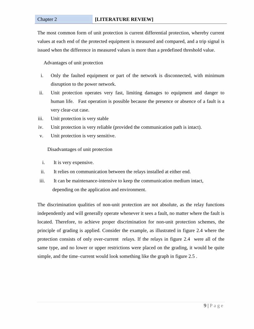
The most common form of unit protection is current differential protection, whereby current
values at each end of the protected equipment is measured and compared, and a trip signal is
issued when the difference in measured values is more than a predefined threshold value.
Advantages of unit protection
i. Only the faulted equipment or part of the network is disconnected, with minimum
disruption to the power network.
ii. Unit protection operates very fast, limiting damages to equipment and danger to
human life. Fast operation is possible because the presence or absence of a fault is a
very clear-cut case.
iii. Unit protection is very stable
iv. Unit protection is very reliable (provided the communication path is intact).
v. Unit protection is very sensitive.
Disadvantages of unit protection
i. It is very expensive.
ii. It relies on communication between the relays installed at either end.
iii. It can be maintenance-intensive to keep the communication medium intact,
depending on the application and environment.
The discrimination qualities of non-unit protection are not absolute, as the relay functions
independently and will generally operate whenever it sees a fault, no matter where the fault is
located. Therefore, to achieve proper discrimination for non-unit protection schemes, the
principle of grading is applied. Consider the example, as illustrated in figure 2.4 where the
protection consists of only over-current relays. If the relays in figure 2.4 were all of the
same type, and no lower or upper restrictions were placed on the grading, it would be quite
simple, and the time–current would look something like the graph in figure 2.5 .

Chapter 2 [LITERATURE REVIEW]
10 | P a g e
Figure 2.4 Application of principle of grading
Figure 2.5 Over current time grading
Chapter 2 [LITERATURE REVIEW]
11 | P a g e
2.5.2 Stability
Stability, also called security, is the ability of the protection to remain inoperative for normal
load conditions (including normal transients like motor starting).Most stability problems
arise from incorrect application of relays and lack of maintenance.
2.5.3 Reliability
Reliability, or dependability, is the ability of the protection to operate correctly in case of a
fault . Reliability is probably the most important quality of a protection system.
2.5.4 Speed of operation
The longer the fault current is allowed to flow, the greater the damage to equipment and the
higher the risk to personnel. Therefore, protection equipment has to operate as fast as
possible, without compromising on stability. The best way to achieve this is by applying unit
protection schemes. However, unit protection is expensive, hence the importance and cost of
the equipment to be protected, and the consequences of an electrical fault, must be
considered and weighed against the cost of very fast protection schemes.
2.5.5 Sensitivity
The term sensitivity refers to the magnitude of fault current at which protection operation
occurs. A protection relay is said to be sensitive when the primary operating current is very
low. Therefore, the term sensitivity is normally used in the context of electrical protection for
expensive electronic equipment, or sensitive earth leakage equipment.
2.6 Protection components
2.6.1 Voltage transformers
Two types of voltage transformers used for protection equipment
i. Electromagnetic type.
ii. Capacitor type.

Chapter 2 [LITERATURE REVIEW]
12 | P a g e
The accuracy of voltage transformers shall be capable to produce secondary voltages.
Voltage transformers for protection are required to maintain reasonably good accuracy over a
large range of voltage from 0 to 173% of normal Connection of voltage transformers.
Electromagnetic voltage transformers may be connected inter phase or between phase and
earth. However, capacitor voltage transformers can only be connected phase-to-earth.[1]
Voltage transformers are commonly used in three-phase groups, generally in star–star
configuration.The Instrument transformers secondary voltages provide a complete replica of
the primary voltages, and any voltage (phase to-phase or phase to-earth) may be selected for
monitoring at the secondary .
To prevent secondary circuits from reaching dangerous potential, the circuits should be
earthed. Earthing should be made at only one point of a VT secondary circuit or galvanically
interconnected circuits. A VT with the primary connected phase-to-earth shall have the
secondary earthed at terminal n. A VT with the primary winding connected across two-
phases, shall have that secondary terminal earthed which has a voltage lagging the other
terminal by 120°. Windings not under use shall also be earthed .
2.6.2 Current transformers
There are two types of current transformers
i. Wound primary type.
ii. Bar primary type .
The wound primary is used for the smaller currents, but it can only be applied on low fault
level installations due to thermal limitations as well as structural requirements due to high
magnetic forces. For currents greater than 100 A, the bar primary type is used. If the
secondary winding is evenly distributed around the complete iron core, its leakage reactance
eliminated .[1]
2.6.3 Fuses
Fuse is the most common and widely used protective device in electrical circuits

Chapter 2 [LITERATURE REVIEW]
13 | P a g e
Rewire able type as the name indicates the fuse can be replaced or „rewired‟ once it fails.
Fusible wire used to be contained in an asbestos tube to prevent splashing of volatile metal.
Advantages
i. Correct rating and characteristic fuse always fitted to a circuit-not open to abuse as
rewire able type.
ii. Arc and fault energy contained within insulating tube-prevents damage.
iii. Normally sealed therefore not affected by atmosphere hence gives more stable
characteristic-reliable grading.
iv. Can operate considerably faster, suitable for higher short-circuit duty (Cartridge type
can handle 100 000 A & Semi-open type can handle 4000 A).
Disadvantages
i Open to abuse due to incorrect rating of replacement elements hence affording
incorrect protection
ii Deterioration of element as it is open to the atmosphere..
2.6.4 Relays
Types of relays
2.6.4.1 Electromechanical Relays
These relays were the earliest forms of relay used for the protection of power systems ,The
mechanical force is generated through current flow in one or more windings on a magnetic
core or cores, hence the term electromechanical relay. The principle advantage of such relays
is that they provide galvanic isolation between the inputs and outputs in a simple, cheap and
reliable form. Therefore for simple on/off switching functions where the output contacts have
to carry substantial currents, they are still used .Electromechanical relays can be classified
into several different types as follows.[3]
i attracted armature
ii moving coil
iii induction
iv thermal

Chapter 2 [LITERATURE REVIEW]
14 | P a g e
v motor operated
vi mechanical
2.6.4.2 Static Relays
The term „static‟ implies that the relay has no moving parts .Their design is based on the use
of analogue electronic devices instead of coils and magnets to create the relay characteristic.
While basic circuits may be common to a number of relays, the packaging was still
essentially restricted to a single protection function per case, while complex functions
required several cases of hardware suitably interconnected .They therefore can be viewed in
simple terms as an analogue electronic replacement for electromechanical relays, with some
additional flexibility in settings and some saving in space requirements. In some cases, relay
burden is reduced, making for reduced CT/VT output requirements . A number of design
problems had to be solved with static relays. In particular, the relays generally require a
reliable source of d.c .power and measures to prevent damage to vulnerable electronic
circuits had to be devised.[3]
2.6.4.3 Digital Relays
Digital protection relays introduced a step change in technology. Microprocessors and
microcontrollers replaced analogue circuits used in static relays to implement relay functions.
Compared to static relays, digital relays introduce A/D conversion of all measured analogue
quantities and use a microprocessor to implement the protection algorithm. The
microprocessor may use some kind of counting technique, or use the Discrete Fourier
Transform (DFT) to implement the algorithm .The limited power of the microprocessors
used in digital relays restricts the number of samples of the waveform that can be measured
per cycle. This, in turn, limits the speed of operation of the relay in certain applications.
Therefore, a digital relay for a particular protection function may have a longer operation
time than the static relay equivalent. However, the extra time is not significant in terms of
overall tripping time and possible effects of power system stability.[3]
2.6.4.4 Numerical Relays
The distinction between digital and numerical relay rests on points of fine technical detail,
and is rarely found in areas other than Protection. They can be viewed as natural

Chapter 2 [LITERATURE REVIEW]
15 | P a g e
developments of digital relays as a result of advances in technology. Typically, they use a
specialized digital signal processor (DSP) as the computational hardware, together with the
associated software tools.
The input analogue signals are converted into a digital representation and processed
according to the appropriate mathematical algorithm. Processing is carried out using a
specialized microprocessor that is optimized for signal processing applications, known as a
digital signal processor or DSP for short. Digital processing of signals in real time requires a
very high power microprocessor. In addition, the continuing reduction in the cost of
microprocessors and related digital devices (memory, I/O, etc.) naturally leads to an
approach where a single item of hardware is used to provide a range of functions („one-box
solution‟ approach). By using multiple microprocessors to provide the necessary
computational performance, a large number of functions previously implemented in separate
items of hardware can now be included within a single item.[3]
2.6.5 Circuit breakers
Where fuses are unsuitable or inadequate, protective relays and circuit breakers are used in
combination to detect and isolate faults. Circuit breakers are the main making and breaking
devices in an electrical circuit to allow or disallow flow of power from source to the load.
These carry the load currents continuously and are expected to be switched ON with loads
(making capacity).
These should also be capable of breaking a live circuit under normal switching OFF
conditions as well as under fault conditions carrying the expected fault current until
completely isolating the fault side (rupturing/breaking capacity) Under fault conditions, the
breakers should be able to open by instructions from monitoring devices like relays. The
relay contacts are used in the making and breaking control circuits of a circuit breaker, to
prevent breakers getting closed or to trip breaker under fault conditions as well as for some
other interlocks .[1]
2.6.5.1 Purpose of circuit breakers
The main purpose of a circuit breaker is to :

Chapter 2 [LITERATURE REVIEW]
16 | P a g e
i Switch load currents.
ii Break normal and fault currents.
iii Carry fault current without blowing itself.
The important characteristics from a protection point of view are
i The speed with which the main current is opened after a tripping impulse is
received.
ii The capacity of the circuit that the main contacts are capable of interrupting.
2.6.5.2 Types of Circuit Breakers
The types of breakers basically refer to the medium in which the breaker opens and closes.
The medium could be oil, air, vacuum or SF6 .[1]
Arc Control Device
A breaker consists of moving and fixed contact, and during the breaker operation, the
contactse broken and the arc created during such separation needs to be controlled. The
breaker is shown in figure 2.6.
Figure 2.6 Arc control circuit-breaker

Chapter 2 [LITERATURE REVIEW]
17 | P a g e
Oil Circuit Breakers
In modern installations, oil circuit breakers, which are becoming obsolete, are being replaced
by vacuum and SF6 breakers. Oil circuit breaker is shown in figure 2.7.
Advantages
i Ability of cool oil to flow into the space after current zero and arc goes out.
ii Cooling surface presented by oil.
iii Absorption of energy by decomposition of oil.
iv Action of oil as an insulator lending to more compact design of switchgear.
Disadvantages
i Inflammability (especially if there is any air near hydrogen).
ii Maintenance (changing and purifying).
Figure 2.7 Oil circuit-breaker
In the initial stages, the use of high-volume (bulk) oil circuit breakers was more common, In
this type, the whole breaker unit is immersed in the oil. This type had the disadvantage of
production of higher hydrogen quantities during arcing and higher maintenance
requirements. Subsequently these were replaced with low oil (minimum oil) types, where the
arc and the bubble are confined into a smaller chamber, minimizing the size of the unit.[1]

Chapter 2 [LITERATURE REVIEW]
18 | P a g e
Air Break Switchgear
Interrupting contacts situated in air instead of any other artificial medium as shown in figure
2.8. Arc is chopped into a number of small arcs by the Arc-shut as it rises due to heat and
magnetic forces. The air circuit breakers are normally employed for 380~480 V distribution.
Figure 2.8 Air break switchgear
SF6 Circuit Breakers
Sulphur-hexaflouride (SF6) is an inert insulating gas, which is becoming increasingly
popular in modern switchgear designs both as an insulating as well as an arc-quenching
medium.[1]
Vacuum Circuit Breakers and Contactors
A circuit breaker is designed for high through-fault and interrupting capacity and as a result
has a low mechanical life. On the other hand, a contactor is designed to provide large number
of operations at typical rated loads of 200/400/600 A at voltages of 1500/3300/6600/11000
V.[1]

Chapter 2 [LITERATURE REVIEW]
19 | P a g e
2.7 Over-current Protection
Over current protection was naturally the earliest protection system to evolve , it is a
discriminative fault protection.
2.7.1 Co-ordination Procedure
Correct over-current relay application requires knowledge of the fault current that can flow in
each part of the network. The data required for a relay setting study are :
i. A one-line diagram of the power system involved, showing the type and rating of the
protection devices and their associated current transformers .
ii. The impedances in ohms, per cent or per unit, of all power transformers, rotating
machine and feeder circuits .
iii. The maximum and minimum values of short circuit currents that are expected to flow
through each protection device .
iv. The maximum load current through protection devices .
v. The starting current requirements of motors and the starting and locked rotor/stalling
times of induction motors .
vi. The transformer inrush, thermal withstand anddamage characteristics .
vii. Decrement curves showing the rate of decay of the fault current supplied by the
generators.
viii. Performance curves of the current transformers .
The relay settings are first determined to give the shortest operating times at maximum fault
levels and then checked to see if operation will also be satisfactory at the minimum fault
current expected .[3]
2.7.2 Principles of Time/Current Grading
Among the various possible methods used to achieve correct relay co-ordination are those
using either time or overcurrent, or a combination of both. The common aim of all three
methods is to give correct discrimination.

Chapter 2 [LITERATURE REVIEW]
20 | P a g e
2.7.2.1 Discrimination by Time
In this method, an appropriate time setting is given to each of the relays controlling the
circuit breakers in a power system to ensure that the breaker nearest to the fault opens first.
Each protection unit comprises a definite-time delay overcurrent relay in which the operation
of the current sensitive element simply initiates the time delay element. each relay time
setting must be long enough to ensure that the upstream relays do not operate before the
circuit breaker at the fault location has tripped and cleared the fault. The main disadvantage
of this method of discrimination is that the longest fault clearance time occurs for faults in
the section closest to the power source, where the fault level (MVA) is highest.[3]
2.7.2.2 Discrimination by Current
The relays controlling the various circuit breakers are set to operate at suitably tapered values
of current such that only the relay nearest to the fault trips its breaker.
There are two important practical points that affect this method of co-ordination:
i. it is not practical to distinguish between a fault at F1 and a fault at F2, since the
distance between these points may be only a few meters, corresponding to a change in
fault current of approximately 0.1% .
ii. in practice, there would be variations in the source fault level .
Discrimination by current is therefore not a practical proposition for correct grading between
the circuit breakers at two points. [3]
2.7.2.3 Discrimination by both Time and Current
Because of the limitations imposed by the independent use of either time or current co-
ordination that the inverse time over-current relay characteristic has evolved. With this
characteristic, the time of operation is inversely proportional to the fault current level .
Illustrates the characteristics of two relays given different current/time settings. For a large
variation in fault current between the two ends of the feeder, faster operating times can be
achieved by the relays nearest to the source, where the fault level is the highest. The
disadvantages of grading by time or current alone are overcome .[3]
Chapter 2 [LITERATURE REVIEW]
21 | P a g e
2.7.3 Standard I.D.M.T. Overcurrent Relays
The current/time tripping characteristics of IDMT relays may need to be varied according to
the tripping time required and the characteristics of other protection devices used in the
network. For these purposes, IEC 60255 defines a number of standard characteristics as
follows:
Standard Inverse (SI)
Very Inverse (VI)
Extremely Inverse (EI)
Definite Time (DT)
2.7.4 Combined IDMT and High Instantaneous Over-current Relays
A high-set instantaneous element can be used where the source impedance is small in
comparison with the protected circuit impedance. This makes a reduction in the tripping time
at high fault levels possible. It also improves the overall system grading by allowing the
'discriminating curves' behind the high set instantaneous elements to be lowered.[3]
One of the advantages of the high set instantaneous elements is to reduce the operating time
of the circuit protection by the shaded area below the 'discriminating curves'. If the source
impedance remains constant, it is then possible to achieve highspeed protection over a large
section of the protected circuit. The rapid fault clearance time achieved helps to minimize
damage at the fault location. a further important advantage gained by the use of high set
instantaneous elements. Grading with the relay immediately behind the relay that has the
instantaneous elements enabled is carried out at the current setting of the instantaneous
elements and not at the maximum fault level.[3]
2.8 Generator protection
Most leading manufacturers of relay equipment today have a multi-function generator relay
on the market, offering a host of functions. The relay has to be configured to meet the
customer‟s requirements and according to the equipment specifications. All of the functions
available need not be required and hence will not be configured. Configuration of complex

Chapter 2 [LITERATURE REVIEW]
22 | P a g e
multi-function relays like a generator protection relay is quite involved and is usually done
by the relay supplier, preferably on a factory test-set before installation.[4]
2.9 Feeder protection
Feeder protection can be applied in two form feeder differential protection or the traditional
over-current and earth fault functions, which are undoubtedly the most commonly used form
of protection.
An over-current and earth fault relay will generally be installed on each feeder cubicle in a
distribution substation, often supporting or as a backup for other specific types of protection,
like differential protection or transformer protection.
The feeder protection relay functions independently and in a very straightforward manner. It
is this characteristic, together with the fact that it is so commonly used, that made this relay.
The ideal candidate to be developed into a versatile, flexible intelligent relay, with powerful
control functions and advanced communications capabilities.[4]
2.10 Transformer protection
The functions of transformer protection relays are less complex than those of generator
protection, and the configuration of the relays is more standard, depending mostly on the
equipment specifications. Generally, differential protection will be applied, with over-current
and earth fault functions as a backup. Larger transformers may also have frequency
protection.
Supplementary protection devices will usually be interfaced to the transformer, e.g. Buchholz
protection, oil temperature,... etc. [4]
2.11 Bus-bar protection
The sole function of busbar protection is to protect the bus-bars of a switchgear panel against
internal faults, that is, faults within the clearly defined bus-bar zone. Bus-bar faults are by
nature quite severe, with high fault currents flowing. The damage to the switchgear panel,

Chapter 2 [LITERATURE REVIEW]
23 | P a g e
which is normally a very expensive piece of equipment as well as a crucial part of the
distribution network, can be extensive if the fault is not cleared quickly. Therefore, bus-bar
protection needs to operate very fast and reliably.[4]
2.12 Primary and Back-up Protection
In the event of failure or non-availability of the primary protection some other means of
ensuring that the faulty sections isolated must be provided. These secondary systems are
referred to as „back-up protection‟.
Back-up protection may be considered as either being „local‟ or „remote‟. Local back-up
protection is achieved by protection which detects an un-cleared primary system fault at its
own location and which then trips its own circuit breakers, e.g. time graded over-current
relays.
Remote back-up protection is provided by protection that detects an un-cleared primary
system fault at a remote location and then issues a local trip command, e.g. the second or
third zones of a distance relay. In both cases the main and back-up protection systems detect
a fault simultaneously, operation of the back-up protection being delayed to ensure that the
primary protection clears the fault if possible. Normally being unit protection, operation of
the primary protection will be fast and will result in the minimum amount of the power
system being disconnected. Operation of the back-up protection will be, of necessity, slower
and will result in a greater proportion of the primary system being lost.[3]
The extent and type of back-up protection applied will naturally be related to the failure risks
and relative economic importance of the system. For distribution systems where fault
clearance times are not critical, time delayed remote back-up protection may be adequate.
For EHV systems, where system stability is at risk unless a fault is cleared quickly, multiple
primary protection systems, operating in parallel and possibly of different types (e.g. distance
and unit protection), will be used to ensure fast and reliable tripping.

Chapter 2 [LITERATURE REVIEW]
24 | P a g e
Back-up over-current protection may then optionally be applied to ensure that two separate
protection systems are available during maintenance of one of the primary protection
systems.
Back-up protection systems should, ideally, be completely separate from the primary
systems.[3]
2.13 Trip Circuit Supervision
The trip circuit includes the protection relay and other components, such as fuses, links, relay
contacts, auxiliary switch contacts, etc., and in some cases through a considerable amount of
circuit wiring with intermediate terminal boards. [3]
These interconnections, coupled with the importance of the circuit, result in a requirement in
many cases to monitor the integrity of the circuit. This is known as trip circuit supervision.
The simplest arrangement contains a healthy trip lamp. The resistance in series with the lamp
prevents the breaker being tripped by an internal short circuit caused by failure of the lamp.
This provides supervision while the circuit breaker is closed, a simple extension gives pre-
closing supervision.
Schemes using a lamp to indicate continuity are suitable for locally controlled installations,
but when control is exercised from a distance it is necessary to use a relay system.[3]

Chapter 3 [Case Study: Baleela Oil-Field Network]
25 | P a g e
CHAPTER THREE
3 Case Study: Baleela Oil-Field Network
3.1 Introduction
In power systems, the analysis of the network is an important step to determine the
performance, both under normal operation and during faults conditions.
Fault levels at different parts of the network, as well as protection coordination are some of
the many important parameters that define the performance of the network. Calculating these
measures and simulation of the system is invaluable in terms of identifying network
problems and suggesting modifications.
3.2 Overview
A site visit was conducted to Baleela Oil-Field network in order to collect the data of the
existing network, collect the uploaded settings of the protection system and investigate the
defects of the existing settings.
The following data was collected:
i. Details of 33kV and 11kV substations in the network.
ii. Single line diagram of the Baleela Power system network.
iii. Impedances of all transmission lines and transformers.
iv. Reactance and MW rating of all generators connected to the network.
v. Load details (MVAr and MW) of the existing network.
vi. Length and type of transmission lines from one substation to another.
The collected data old settings is shown in appendix A and B respectivly.

Chapter 3 [Case Study: Baleela Oil-Field Network]
26 | P a g e
3.3 Baleela oil-field network description
Baleela network have its own power station located at CPF with installed capacity of 34.78
MW to supply power to FULA, FNE, JAKE, MOGA and KEYI fields as described in the
following sections.
Figure 3.1 Geographic description of BALEELA network
3.3.1 CPF station
This station consists of four Rolls Royce gas engine units of 5.1 MVA, two Wartsila gas
engine units of 7.588 MVA, three Wartsila diesel engine units of 2.5 MVA , 11kV/33kV
substation and three feeders, 33kV to KEYI, 33kV to FNE and 33kV to MOGA .
Table 3.1 shows real and reactive power for CPF loads at busbar (A).

Chapter 3 [Case Study: Baleela Oil-Field Network]
27 | P a g e
Table 3.1: Real and reactive power for CPF loads at busbar A
Table 3.2 shows real and reactive power for CPF loads at busbar (B).
Table 3.2: Real and reactive power for CPF loads at busbar (B)
3.3.2 KEYI Substation
This substation is of single busbar type with two bus couplers. It is composed of two power
transformers 33/11kV linking the 33 and 11 kV busbars with rated power 2 MVA .
Table 3.3 shows real and reactive power for KEIY loads at busbar (A & B)
Table 3.3: Real and reactive power for KEIY loads at busbar (A & B)
3.3.3 FNE Substation
This substation is of single busbar type with two bus couplers, one section CB and two
section isolators and it is composed of two power transformers 33/11kV linking the 33 and
11 kV busbars with rated power 3.5 MVA .
Table 3.4 shows real and reactive power for FNE loads at busbar (A & B)

Chapter 3 [Case Study: Baleela Oil-Field Network]
28 | P a g e
Table 3.4: Real and reactive power for FNE loads at busbar A & B
3.3.4 Moga Substation
This substation is of a single busbar type with two bus couplers. It is composed of two power
transformers 33/11 kV linking the 33 and 11 kV busbars with rated Power 2 MVA. MOGA
substation has two outgoing 33kv transmission lines feeding JAKE substation .
Table 3.5 shows real and reactive power for MOGA loads at busbar (A & B)
Table 3.5: Real and reactive power for MOGA loads at busbar (A & B)
3.3.5 JAKE Substation
This substation is of single busbar type with two bus couplers. It is composed of two power
transformers 33/11 kV linking the 33 and 11 kV busbars with rated power 2.5 MVA .
Table 3.6 shows real and reactive power for JAKE loads at busbar (A & B)
Table 3.6: real and reactive power for JAKE loads at busbar (A & B)

Chapter 3 [Case Study: Baleela Oil-Field Network]
29 | P a g e
3.4 Network Implementation and Simulation
The simulation program used in this study is ETAP 12.6 (Electrical Transient and Analysis
Program). The circuit was constructed using all the required data and parameters as shown in
the single line diagram in figure 3.2.
Figure 3.2 Baleela Oil-Field Network Single Line Diagram
The single-line diagram includes all substations with the load of each feeder in each
substation, power transformers (rating, winding connection and grounding means), Incoming
and outgoing lines.
The ETAP Single-Line Diagram is used to create and visually manage the electrical
schematics and electrical drawings of Baleela network. It will also be used to perform
multiple simultaneous scenario simulations.

Chapter 3 [Case Study: Baleela Oil-Field Network]
30 | P a g e
3.5 Simulation Scenarios (Old settings)
3.5.1 Overview
All outgoing transmission lines relays setting was DMT with time delay (0.1 or 0.2 sec )
which will lead to trip of the outgoing transmission line for any fault that occurs at any
substation‟s feeder. Hence the protection scheme is miss-coordinated.
3.5.2 Three-Phase Fault Scenarios (phase)
To demonstrate this, JAKE substation was taken as a case study. Its existing protection
settings are uploaded in ETAP software. Tables in appendix (B) show existing settings of
JAKE substation.
The reason behind taking CPF-JAKE line as a case study is that it is the longest line, and
gives many faulty operations of relays.
3.5.2.1 A three phase fault on JAKE 11kV feeder
A three phase fault was simulated at (CH05 TR7802A) feeder as shown in figure 3.3
Figure 3.3 Three phase fault on JAKE (CH05 TR7802A) feeder

Chapter 3 [Case Study: Baleela Oil-Field Network]
31 | P a g e
The sequence of operation for three phase fault on JAKE 11kV feeder is shown in figure 3.4.
Figure 3.4 sequence of operation for JAKE 11kV feeder
From figure 3.4, it's clear that the bus section relay (relay 32) and the two relays at the
primary side of the two transformers (relay 44 and relay 45) tripped at the same time as the
faulted feeder relay (relay 47),which means that the whole substation is out for a single three
phase fault at the downstream feeder.
Also the two relays of the two feeders (relay 46 and relay 56) tripped at the same time (300
milliseconds) due to the high reverse currents of the motors.
The correct sequence of operation is that the feeder relay (relay 47) must trip first followed
by the bus section relay (relay 32) delayed by at least 150 millisecond then the two 11 kv
incomers (relay 33 & 43) also delayed by at least 150 millisecond, then the two relays of the
primary side of the transformer.

Chapter 3 [Case Study: Baleela Oil-Field Network]
32 | P a g e
3.5.2.2 A three phase fault at the transmission line
A three phase fault was simulated at MOGA-JAKE transmission line as shown in figure 3.5.
Figure 3.5 Three phase fault at MOGA-JAKE transmission line
The sequence of operation for three phase fault at MOGA-JAKE line is shown in figure 3.6
Figure 3.6 sequence of operation for fault at MOGA-JAKE transmission line

Chapter 3 [Case Study: Baleela Oil-Field Network]
33 | P a g e
From figure 3.6, it's clear that the two relays of the two parallel transmission lines going from
CPF to MOGA (relay 217 and relay 230) tripped instantaneously at zero second. Hence
MOGA substation will totally blackout for any fault that occur at the transmission line
going to Jake substation .hence protection scheme is miss-coordinated.
The correct sequence of operation is that the sending end of the two transmission line (going
to JAKE) relay (relay 250( must trip first followed by the bus section relay (relay 57) delayed
by at least 150 millisecond then the receiving end of the transmission line (coming from
CPF) relay (relay 249) also delayed by 150 millisecond.
3.5.2.3 A three phase fault at CPF 33kV bus-bar
A three phase fault at CPF 33kV bus-bar (B) was simulated as shown in figure 3.7
Figure 3.7 Three phase fault at CPF 33kV bus-bar (B)

Chapter 3 [Case Study: Baleela Oil-Field Network]
34 | P a g e
The sequence of operation for three phase fault at CPF 33kV bus-bar B is shown in figure
3.8.
Figure 3.8 sequence of operation for a fault on CPF 33kV bus-bar (B)
From the figure 3.8, is clear that all relays of the feeders in CPF (bus-bar A & B 11kV)
tripped due to the reverse current before the bus section.
Also the tripping of the bus section was delayed (after 500 millisecond), also 33kv incomer
relay did not trip. Hence protection scheme is miss-coordinated.
The correct sequence of operation is that the bus section relay (relay 171) must trip first then
the two 33kv incomers of CPF relays delayed by at least 150 millisecond then the two relays
of the primary side of the transformer.

Chapter 3 [Case Study: Baleela Oil-Field Network]
35 | P a g e
3.5.3 Line-To-Ground Fault Scenarios (earth fault)
3.5.3.1 Line -To-Ground fault on KEYI 11kV feeder (feeder TR-6802)
Line -To-Ground fault is simulated on KEYI 11kV feeder (feeder TR-6802) as shown in
figure 3.9
Figure 3.9 Line-to-Ground fault on KEYI 11kV feeder
Figure 3.10 shows the sequence of operation for Line-to-Ground fault on KEYI 11kV feeder
Figure 3.10 The sequence of operation for Line-to-Ground fault on KEYI 11kV feeder

Chapter 3 [Case Study: Baleela Oil-Field Network]
36 | P a g e
From figure 3.10, it is clear that the bus-section relay (relay 98) is disabled which means that
the two 11kv bus-bars will be lost if the feeder relay failed to operate .also the earth fault
element of the two 11kv incomers is delayed by 600 milliseconds.
3.5.3.2 Line -To-Ground fault at transmission line between CPF and KEYI
Line -To-Ground fault was simulated at transmission line between CPF and KEYI as shown
in figure 3.11
Figure 3.11 Line -To-Ground fault at transmission line between CPF and KEYI
Figure 3.12 shows the sequence of operation for Line -To-Ground fault at CPF- KEYI line
Figure 3.12 Sequence of operation for Line-to-Ground fault at CPF-KEYI transmission
line

Chapter 3 [Case Study: Baleela Oil-Field Network]
37 | P a g e
From figure 3.12, the earth fault of the sending end relay of the transmission line (Relay 178)
operates instantaneously at Zero millisecond. However, it is clear that the earth fault element
of the bus-coupler relay is disabled and this will cause both transformers to be tripped when
the transmission line relay didn‟t operate. In addition, the earth fault element of the two 33kV
incomers was delayed by 1500 millisecond. This delay at fault current of 1260A will damage
the electrical equipments.
After investigation of the above fault scenarios, we found that the major cause of miss
coordination behavior of the relays was due to the use of the definite minimum time
philosophy.
3.6 Concept of DMT and I.D.M.T
3.6.1 Definite Time Relay
In this type of relay the setting may be changed to deal with different levels of current by
using different operating times.
The operation rules for definite-time-delayed over current relays can be expressed in the
following equation:
𝑇 =2𝑇𝑠
1+𝑠𝑔𝑛 (𝐼−𝐼𝑆) 3.1
Where T: relay operation time
Is: current setting threshold
I: current detected by relay (after relay filtering)
Ts: relay delay setting
Sgn: sign function (sign taken from the result, value being 1)
Equation (3.1) above means that:
𝑻 = ∞ 𝑰 < 𝑰𝑺𝑻𝑺 𝑰 > 𝑰𝑺

Chapter 3 [Case Study: Baleela Oil-Field Network]
38 | P a g e
The characteristic curve of a definite time relay is shown in figure 3.13
Figure 3.13 Definite time relay curve
Definite time protection is more selective as the operating time can be set in fixed steps.
However, faults close to the source, which results in higher currents may be cleared in a
relatively long time.
To enhance the protection scheme performance we must use a more flexible philosophy of
the current- time characteristic such as inverse definite minimum time philosophy.
3.6.2 Inverse Time Relays
These relays operate in a time that is inversely proportional to the fault current. Inverse time
relays have the advantage of that shorter tripping times can be achieved without risking the
protection selectivity. These relays are classified based on their characteristic curves, which
define the speed of operation as inverse, very inverse or extremely inverse. Their defining
curve shape is shown in Figure 3.14.
Figure 3.14 Inverse time relay curve

Chapter 3 [Case Study: Baleela Oil-Field Network]
39 | P a g e
According to IEC and IEEE standards, the characteristic of inverse-time over current relays
can be depicted by the following expression:
𝑻 =𝑪
𝑰
𝑰𝑺 𝜶
−𝟏 3.2
Where:
T: relay operation time
C: constant for relay characteristic, proportional to the time multiplier setting
Is: current setting threshold
I: current detected by relay (after relay filtering), I>Is
α: constant representing inverse-time type, α>0
By assigning different values to α and C, there are different types of inverse characteristics.
Table 3.7 shows the definitions of various types by IEC and IEEE respectively.
Table 3.7: Parameters for different types of inverse characteristic
Curve Type
α C
IEC IEEE IEC IEEE
Standard Inverse (SI) 0.02 0.02 0.14 0.0515
Very Inverse (VI) 1 2 13.5 19.61
Extreme Inverse (EI) 2 2 80 28.2
Long Inverse (LI) 1 - 120 -

Chapter 4 [Implementation and Results]
40 | P a g e
CHAPTER FOUR
4 Implementation and Results
4.1 Introduction
This chapter introduces the results obtained from Relay coordination study. and the new
settings will be used to obtain a well coordinated network.
4.2 Analysis Conditions
The analysis was performed under the normal conditions of generators ( two Rolls Royce gas
engine units of 5.1 MVA and two Wartsilla (gas) units of 7.588 MVA), operating according
to the site visit. The loads are the lumped loads and they were modeled exponentially.
4.3 Protection Settings Coordination Results
A completely new coordinated scheme was designed. It discriminated the network in
different zones. It starts first by coordinating the over-current elements, for different paths
from furthest downstream up to the generators. Next the Earth Fault relays were coordinated
for the same paths and finally the instantaneous elements.
The entire definite-minimum-time (DMT) scheme was replaced with the more flexible
inverse-definite-minimum-time (IDMT) scheme philosophy for first stage of both over-
current and earth fault.
The result is that the new philosophy and settings provide a backup over current and earth
fault system that is streamlined and does not result in some gross miss-operations such as
loss of 33kV feeders in CPF due to a fault on the 11kV bus of JAKE. For all substations, the
pickup settings for earth fault were coordinated by taking thirty percent of the normal full
load current.

Chapter 4 [Implementation and Results]
41 | P a g e
4.4 New Relay Settings Coordination
4.4.1 Over-current Settings
4.4.1.1 JAKE –MOGA
The coordination started from far downstream at 11kV feeder of JAKE substation until
MOGA 33kV bus-bar (MOGA 33kV outgoing relay), this coordination by both current and
time to ensure adequate fault isolation. The coordination is shown in next figures .
The new coordination is shown in figure 4.1
Figure 4.1 The new phase [O/C] settings for JAKE-MOGA path relays

Chapter 4 [Implementation and Results]
42 | P a g e
4.4.1.2 MOGA – CPF
The coordination is shown in figure 4.2
Figure 4.2 The new phase [O/C] settings for MOGA-CPF path relays

Chapter 4 [Implementation and Results]
43 | P a g e
4.4.1.3 FNE - CPF
The coordination is shown in figure 4.3
Figure 4.3 The new phase [O/C] settings for FNE-CPF path relays

Chapter 4 [Implementation and Results]
44 | P a g e
4.4.1.4 KEYI - CPF
The coordination is shown in figure 4.4
Figure 4.4 The new phase [O/C] settings for KEYI-CPF path relays

Chapter 4 [Implementation and Results]
45 | P a g e
4.4.2 Earth Fault Settings
4.4.2.1 Settings for JAKE up to the secondary of its transformer
The coordination is shown in figure 4.5
Figure 4.5 New earth fault settings for JAKE up to the secondary of its transformer

Chapter 4 [Implementation and Results]
46 | P a g e
4.4.2.2 Settings from JAKE primary of the transformer up to CPF
The coordination is shown in figure 4.6
Figure 4.6 New earth fault settings from JAKE primary of the transformer up to CPF

Chapter 4 [Implementation and Results]
47 | P a g e
4.4.2.3 Settings for MOGA up to the secondary of its transformer
The coordination is shown in figure 4.7
Figure 4.7 New earth fault settings For MOGA up to secondary of its transformer

Chapter 4 [Implementation and Results]
48 | P a g e
4.4.2.4 Settings from MOGA primary of the transformer up to CPF
The coordination is shown in figure 4.8
Figure 4.8 New earth fault settings from MOGA primary of the transformer up to CPF

Chapter 4 [Implementation and Results]
49 | P a g e
4.4.2.5 Settings for FNE up to Secondary of its transformer
The coordination is shown in figure 4.9
Figure 4.9 New earth fault settings for FNE up to secondary of its transformer

Chapter 4 [Implementation and Results]
50 | P a g e
4.4.2.6 Settings from FNE primary of the transformer up to CPF
The coordination is shown in figure 4.10
Figure 4.10 New earth fault settings from FNE primary of the transformer up to CPF

Chapter 4 [Implementation and Results]
51 | P a g e
4.4.2.7 Settings for KEYI up to secondary of its transformer
The coordination is shown in figure 4.11
Figure 4.11 New earth fault settings from KEYI up to secondary of its transformer

Chapter 4 [Implementation and Results]
52 | P a g e
4.4.2.8 Settings from KEYI primary of the transformer up to CPF
The coordination is shown in figure 4.11
Figure 4.12 New earth fault settings from KEYI primary of the transformer up to CPF

Chapter 4 [Implementation and Results]
53 | P a g e
4.4.2.9 Settings from CPF primary of its transformer up to 11kV bus section
The coordination is shown in figure 4.11
Figure 4.13 New earth fault settings for CPF primary of its transformer up to 11kV bus
section

Chapter 4 [Implementation and Results]
54 | P a g e
4.5 Simulation Scenarios (new settings)
4.5.1 Overview
Now when applying the new settings mentioned in above section into ETAP to simulate the
sequence of operations for the same type of faults as mentioned in Chapter three, the results
showed that almost all the problems associated with the old settings has been resolved and
the network is well coordinated.
4.5.2 Three-Phase Fault Scenarios
4.5.2.1 A three phase fault on JAKE 11kV feeder
A three phase fault was simulated on JAKE 11kV feeder as shown in figure 4.14
Figure 4.14 Three phase fault on JAKE 11kV (CH05 TR7802A) feeder

Chapter 4 [Implementation and Results]
55 | P a g e
The sequence of operation for three phase fault on JAKE 11kV feeder is shown in figure 4.15
Figure 4.15 sequence of operation for a three phase fault on JAKE 11kV feeder
from figure 4.15 it is clearly that the feeder relay (relay 47) was tripped first at Zero second
by instantaneous element followed by the bus section relay (relay 32) delayed after 170
millisecond then the two 11kV incomers (relay 33 & 43) after 370 millisecond. After that the
two relays of the primary side of the transformers (relay 44 & 45) were tripped. Now this is
the correct sequence of operation, also grading margin between relays is maintained above
150 millisecond. Hence, miss-coordination will not occur as demonstrated in section
(3.5.2.1).
From above sequence of operation, the discrimination was conducted correctly which was
not achieved at the old setting as shown in section (3.5.2.1).
4.5.2.2 A three phase fault at the transmission line
A three phase fault was simulated at MOGA-JAKE transmission line as shown in figure 4.16

Chapter 4 [Implementation and Results]
56 | P a g e
Figure 4.16 Three phase fault at MOGA-JAKE transmission line
The sequence of operation for three phase fault at MOGA-JAKE transmission line is shown
in figure 4.17
Figure 4.17 sequence of operation for a three phase fault at MOGA-JAKE line

Chapter 4 [Implementation and Results]
57 | P a g e
Comparing figure 4.17 with that of chapter three (figure 3.6), it's clearly that the correct
sequence of operation is now achieved. Also, the grading margin between relays is
maintained above 150 millisecond.
Another point to shed the light on here, is the benefits of using the instantaneous current at
the beginning of the line (or on the transformer primary) to isolate the faults on the line as
quickly as possible. In this case, the instantaneous element enabled relay 250 to trip the line
at Zero seconds.
4.5.2.3 A three phase fault at CPF 33kV bus-bar
A three phase fault was simulated at CPF 33kV bus-bar (B) as shown in figure 4.18.
Figure 4.18 Three phase fault at CPF 33kV bus-bar (B)

Chapter 4 [Implementation and Results]
58 | P a g e
The sequence of operation for three phase fault at CPF 33kV bus-bar (B) is shown in figure
4.19
Figure 4.19 sequence of operation for three phase fault at CPF 33kV bus-bar (B)
Comparing this sequence of operation , for three phase fault on CPF 33kV bus-bar (B), with
the old setting, it's obvious that the correct sequence of operation is now achieved. However,
the bus coupler relay (Relay 171) had operated after a long period of time (1.185s) and this is
a situation that needs improving.
One possible and necessary solution is to install bus-bar differential protection on CPF 33kV
bus-bars to isolate this type of fault quickly.
4.5.3 Line-To-Ground Fault Scenarios (earth fault)
4.5.3.1 Line -To-Ground fault on KEYI 11kV feeder (feeder TR-6802)
Line -To-Ground fault is simulated on KEYI 11kV feeder (feeder TR-6802) is shown in
figure 4.20

Chapter 4 [Implementation and Results]
59 | P a g e
Figure 4.20 Line-to-Ground fault on KEYI 11kV feeder
Figure 4.21 shows the sequence of operation for earth fault on KEYI 11kV feeder

Chapter 4 [Implementation and Results]
60 | P a g e
Figure 4.21 The sequence of operation for Line-to-Ground fault on KEYI 11kV feeder
From figure 4.21 it is clear that the feeder relay (relay 102) tripped instantanously at zero
millisecond followed by the bus-section relay (relay 98) at 170 millisecond then the two 11kv
incomers (relay 97 and relay 107 ) tripped at 340 millisecond.

Chapter 4 [Implementation and Results]
61 | P a g e
4.5.3.2 Line -To-Ground fault at transmission line between CPF and KEYI
Line -To-Ground fault was simulated at transmission line between CPF and KEYI is shown
in figure 4.22
Figure 4.22 Line -To-Ground fault at transmission line between CPF and KEYI

Chapter 4 [Implementation and Results]
62 | P a g e
Figure 3.12 shows the sequence of operation for fault at transmission line between CPF and
KEYI
Figure 4.23 sequence of operation for Line-to-Ground fault on CPF- KEYI transmission
line
From figure 4.2 it is clear that the feeder relay (relay 178) tripped instantanously at zero
millisecond followed by the buscoupler relay (relay 171) at 821 millisecond then the two
33kv incomers (relay 8and relay 10 ) tripped after 1 second.

Chapter 4 [Implementation and Results]
63 | P a g e
4.6 Summery
Now and after this study for all substations the coordination has been achieved as follows:
The coordination of the over current settings starts at far downstream of the JAKE 11
kV feeder relay with IDMT delay curve and minimum time multiplier setting (TMS)
= 0.025.
The next relay is the bus section relay which was coordinated using pickup above the
rated current passing through the secondary side of the transformer, with a TMS=
0.05 , in order to isolate the healthy load from the faulty side.
Then 11 kV incomer relay with pickup above the rated current on low voltage side of
33/11 kV main transformer with a TMS = 0.1. Also 33 kV transformer feeders were
coordinated with a slightly higher pickup than the low voltage side of 33/11 kV main
transformer, but with the same TMS to ensure that the two relays will operate at the
same time in order to completely isolate the main transformer (i.e. reacts as a
differential protection).
Also, instantaneous element was implemented on the high voltage side of 33/11 kV
main transformer as a back-up protection to ensure fast adequate operation of the
relay.
The bus coupler on normal operation is opened, but for worst case scenario it‟s
coordinated with a pickup = 0.4 and TMS = 0.15.
The 33 kV incomer is coordinated with pickup = 0.75 and TMS = 0.2.
Then the sending end of the transmission line is coordinated with a pickup slightly
higher than the receiving end but with the same TMS = 0.2 to isolate both ends of the
line in almost the same time.
An instantaneous element was implemented at the sending end of the transmission
line as a back-up protection to ensure fast adequate operation of the relay.
Then the bus coupler of the 33kv bus bar of MOGA is coordinated with TMS = 0.72.
Then the outgoing is coordinated with pickup = 0.9 for the receiving end and 1.15 for
the sending end with the same TMS= 0.3.

Chapter 4 [Implementation and Results]
64 | P a g e
The earth fault settings were coordinated in the same way as for over-current in TMS
setting, furthermore the pickup settings were coordinated by taking thirty percent
from over-current pickup settings.
This coordination was performed to all substations (KEYI, FNE, MOGA, and JAKE)
except the feeders of the CPF main station because these feeders are directly
connected to the generation side.
In all 11 kV feeders of the CPF main station the pickup was raised up to avoid the
inrush current of the big motors, and the proposed settings is given in Appendix C.
Table 4.1 shows each scenario with its coordination status.
Table 4.1 Coordination status for each scenario
Scenario No Scenario description Uploaded settings Status of
coordination
4.5.2.1
Three phase fault on
JAKE 11kV feeder
(CH05 TR7802A)
Old settings
Miss coordinated
New settings Well coordinated
4.5.2.2
Three phase fault on
outgoing
transmission line
from MOGA to
Old settings
Miss coordinated
New settings Well coordinated
4.5.2.3
Three phase fault on
CPF 33kV bus-bar B
Old settings
Miss coordinated
New settings
Well coordinated
4.5.3.1
Line-To-Ground
fault on KEYI 11kV
feeder (TR6802
feeder)
Old settings
Will coordinated (but
with a large time
delay)
New settings Well coordinated
4.5.3.2
Line-To-Ground
fault on transmission
line between CPF
and KEYI
Old settings
Will coordinated (but
with a large time
delay)
New settings Well coordinated

Chapter 5 [Conclusion and Recommendations]
65 | P a g e
CHAPTER FIVE
5 Conclusion
5.1 Protection Settings Coordination The over-current protection settings coordination has been achieved successfully, and the
sequence of tripping starts at far downstream of the JAKE 11 KV feeder relay with IDMT
curve, then the 11 kV bus section relay, 11 kV incomer and 33 KV transformer feeders, Then
the 33 kV bus coupler, and finally the 33 kV incomer at 33 kV bus-bar on MOGA substation
and the outgoing transmission lines at the CPF main station. For the remaining substations,
the phase and earth fault settings were coordinated in the same way as for JAKE to CPF path.
Furthermore, the pickup settings for earth fault were coordinated by taking thirty percent of
the normal full load current. Also, an instantaneous element was performed successfully as a
back-up protection
5.2 Objectives Achieved
Baleela Oil-Field power Network has been simulated and analyzed using ETAP
software.
From simulating the currently-used relay settings, the disadvantages have been
observed.
Then, the optimum characteristics, which is IDMT, is chosen and performed for both
phase and earth fault protections on this network.
Instantaneous element is installed as a back-up protection.
With the use of the new settings, Baleela Network has been well coordinated.
Chapter 5 [Conclusion and Recommendations]
66 | P a g e
5.3 Recommendations
It‟s recommended to replace the currently installed DMT settings with the new
IDMT settings for both overcurrent and earth faults into all relays at Baleela network.
It‟s recommended to install busbar differential protection at CPF and MOGA 33KV
busbars to isolate the faults on them as quickly as possible. Because both the new and
old settings showed a high operating time for such faults.
Relay Settings coordination for both phase and earth faults in all substations should be re-
assessed on regular basis, because the nature of loads are dynamically changed.
It's recommended that all transformers and transmission lines relays to trip the two
breakers in order to entirely isolate the faulty transformer or transmission line.
It‟s recommended to re-calculate all the spare feeders‟ normal current before they are
connected to any load.

67 | P a g e
References
[1]L.G.Hewitson, Mark Brown, Ramesh Balakrishnan, “Practical Power Systems Protection“
[2]J. Lewis Blackburn and Thomas J. Domain, “Protective Relaying Principles and
Applications”, Third Edition 2007.
[3] Areva, “Network Protection and Automation Guide”, First edition july 2002.
[4] Cobus strauss."Practical Electrical Network Automation and Communication Systems".
[5]Petro Energy Company E&P Co., Ltd., “Draft Report”
[6] Robert B. Hicke, “Electrical Engineer's Portable Handbook”.
[7]Y.G. Paithanka & S.R. Bhide, “Fundamentals of Power System Protection”.
Visvesvaraya National Institute of Technology Nagpur, 2003.

68 | P a g e
6 Appendix A
A.1 Transformer Data
Table A.1 shows a power transformers technical data.
Table A.1 Power Transformers Technical Data

69 | P a g e
A.2 X/R Ratio for each transformer
Table A.1 shows X/R ratio for each transformer using the transformer rated MVA and
copper losses.
Table A. 2 X/R ratio for each transformer using the transformer rated MVA and copper
losses

70 | P a g e
A.3 Transmission Lines Data
Table A.3 shows transmission lines data
Table A. 3 Transmission Lines Data
A.4 The generators dynamic data
Table A.4 shows The generators dynamic data
Table A. 4 The generators dynamic data

71 | P a g e
Appendix B
7 OLD SETTINGS
B.1 OLD SETTINGS – FNE SUBSTATION
Table B. 1 11kV Feeders on 1stBusbar
Feeder
Overcurrent protection [50/51] Earth protection [50N/51N] Relay
Type
C.T.
ratio
De
lay
cur
ve
typ
e
Current
setting
Time
settin
g
Instantaneous
protection
(DMT)
Ti
m
e
C.
T.
rat
io
De
lay
cur
ve
typ
e
Curre
nt
settin
g
Tim
e
setti
ng
Instantaneous
protection
(DMT)
Tim
e
BH01: Spare
Feeder
50/1 D
M
T
I
>0.48𝐼𝑛
2 I >>0.55𝐼𝑛
I >>>5.38𝐼𝑛
0.
5s
0 s
50
/1
D
M
T
I >
0.2𝐼𝑒
0.5 I >>0.4 𝐼𝑒 0 s
Tamco
Micom
P123
BH02: Spare
Feeder
50/1 D
M
T
I
>0.48𝐼𝑛
2 I >>0.55𝐼𝑛
I >>>5.38𝐼𝑛
0.
5s
0 s
50
/1
D
M
T
I >
0.2𝐼𝑒
0.5 I >>0.4 𝐼𝑒 0 s
Tamco
Micom
P123
BH03: Spare
Feeder
50/1 D
M
T
I
>0.48𝐼𝑛
2 I >>0.55𝐼𝑛
I >>>5.38𝐼𝑛
0.
5s
0 s
50
/1
D
M
T
I >
0.2𝐼𝑒
0.5 I >>0.4 𝐼𝑒 0 s
Tamco
Micom
P123
BH04:
1#RMUFeed
er
150/1 D
M
T
I > 0.5
𝐼𝑛
0.02 I >>0.5𝐼𝑛
I >>>0.6𝐼𝑛
0 s
0 s
50
/1
D
M
T
SI
I >
0.1𝐼𝑒
0.05 I >> 0.2 𝐼𝑒
I>>0.2 𝐼𝑒
0 s
0 s
Tamco
MicomP
123

72 | P a g e
BH05: TR-
8802A
100/1 D
M
T
I >
0.76𝐼𝑛
2 I >>0.98 𝐼𝑛
I >>>3.01 𝐼𝑛
0.
3s
0 s
50
/1
ID
M
T
SI
I >
0.2𝐼𝑒
0.5 I > 0.4 𝐼𝑒 0 s Tamco
Micom
P123
Table B. 2 11kV Feeders on 2nd
Busbar
Feeder
Overcurrent protection [50/51] Earth protection [50N/51N] Relay
Type
C.T.
ratio
Dela
y curv
e
type
Current
setting
Time
setting
Instantaneous
protection (DMT)
Time C.T.
ratio
Dela
y curve
type
Curren
t setting
Time
setting
Instantaneo
us protection
(DMT)
Tim
e
BH12: TR-8802B 100/1
DMT
I >
0.76 𝐼𝑛
0.02 I >>0.98𝐼𝑛
I >>>3.01𝐼𝑛
0.3 s
0 s
50/1 DMT I >
0.2𝐼𝑒
0.5 I > 0.4 𝐼𝑒 0 s Tamco Micom
P123
BH13: Spare Feeder
100/1
DMT
I >
0.75𝐼𝑛
0.025 I >>1.08𝐼𝑛
I >>>16.41𝐼𝑛
0 s
0 s
50/1 DMT I >
0.2𝐼𝑒
0.025 I > 0.4 𝐼𝑒 0 s Tamco Micom
P123
BH14: Spare
Feeder
40/1 DM
T
I >
0.75 𝐼𝑛
0.025 I >>1.08𝐼𝑛
I >>>16.40𝐼𝑛
0 s
0 s
50/1 DMT I >
0.2𝐼𝑒
0.025 I > 0.4 𝐼𝑒 0 s Tamco
Micom P123
BH15: 1# RMU
Feeder
150/
1
DM
T
I > 0.4
𝐼𝑛
0.025 I >>0.6𝐼𝑛
I >>>0.9𝐼𝑛
0 s
0 s
50/1 DMT I >
0.2𝐼𝑒
0.025 I > 0.4 𝐼𝑒 0 s Tamco
Micom P123
BH16: Spare
Feeder
100/
1
DM
T
I >
0.75 𝐼𝑛
0.025 I >>4.43𝐼𝑛
I >>5.01𝐼𝑛
0 s
0 s
50/1 DMT I >
0.2𝐼𝑒
0.025 I > 0.4 𝐼𝑒 0 s Tamco
Micom P123
Table B. 3 11kV Incomers
Incomer Overcurrent protection [50/51] Earth protection [50N/51N] Relay
Type
C.T.
ratio
Delay
curve
type
Current
setting
Time
setting
Instantaneous
protection
(DMT)
Time C.T.
ratio
Delay
curve
type
Current
setting
Time
setting
Instantaneous
protection
(DMT)
Time

73 | P a g e
BH07: 1#
Incomer
200/1 DMT I >
0.8 𝐼𝑛
2 I >>1.5𝐼𝑛
I >>>2.5𝐼𝑛
0.5 s
0.1s
200/1 DMT I >
0.1𝐼𝑒
0.1 s. I >> 0.15 𝐼𝑒
I >>> 0.4 𝐼𝑒
0.6 s
0.1 s
Tamco
Micom P121
BH10: 2#
Incomer
200/1 DMT I >
0.8 𝐼𝑛
2 I >>1.5𝐼𝑛
I >>>2.5𝐼𝑛
0.5 s
0.1s
200/1 DMT Disabled Tamco
Micom P121
Table B.4 33kV Transformer Feeders
Transformer
feeders
Overcurrent protection [50/51] Earth protection [50N/51N] Relay
Type C.
T.
rati
o
Dela
y
curv
e
type
Curren
t
setting
Time
settin
g
Instantaneo
us
protection
(DMT)
Tim
e
C.T.
ratio
Delay
curve
type
Current
setting
Time
setting
Instantaneo
us
protection
(DMT)
Time
2#
Transformer-A
75/
1
DM
T
I
>0.8𝐼𝑛
0.1 Disabled 50/1 DMT I >
0.6𝐼𝑒
0.025 Disabled Schneider
P142
9#
Transformer-B
75/
1
DM
T
I
>0.8𝐼𝑛
0.1 Disabled 50/1 DMT I >
0.6𝐼𝑒
0.025 Disabled Schneider
P142
Table B. 5 33kV Bus coupler
Bus
Coupler
Overcurrent protection [50/51] Earth protection [50N/51N] Relay
Type C.T.
ratio
Delay
curve
type
Current
setting
Time
setting
Instantaneous
protection
(DMT)
Time C.T.
ratio
Delay
curve
type
Current
setting
Time
setting
Instantaneous
protection
(DMT)
Time
6# Bus
coupler
150/1 DMT
I >
0.4𝐼𝑛
0.125 Disabled 150/1 Disabled Disabled Schneider
P143

74 | P a g e
Table B. 6 33kV Incomers
Incomer Overcurrent protection [50/51] Earth protection [50N/51N] Relay Type
C.T.
ratio
Delay
curve
type
Current
setting
Time
setting
Instantaneous
protection
(DMT)
Time C.T.
ratio
Delay
curve
type
Current
setting
Time
setting
Instantaneous
protection
(DMT)
Time
4# Incoming
1
150/1 DMT I >
0.5𝐼𝑛
0.15 Disabled 50/1 DMT I >
1.14𝐼𝑒
0.15 Disabled Schneider P143
7#
Incoming 2
150/1 DMT I >
0.5𝐼𝑛
0.15 Disabled 50/1 DMT I >
1.14𝐼𝑒
0.15 Disabled Schneider
P143
Table B. 7 11kV Bus-section & 11kV two Incomers Directional Protection
Incomer Overcurrent protection [67] Earth protection [67N] Relay
Type
C.T. ratio
Delay curve
type
Current setting
Time
sett
ing
Instantaneous
protection
(DMT)
Time
C.T. ratio
Delay curve
type
Current setting
Time setting
Instantaneous protection
(DMT)
Time
BH07: 1#
Incomer
200/
1
DMT I
>0.85𝐼𝑛
0.0
75
Disabled 40/1 DMT I >
0.8𝐼𝑒
0.1 Disabled Tamco
P127
BH10: 2#
Incomer
200/
1
DMT I >
0.85𝐼𝑛
0.0
75
Disabled 40/1 DMT I >
0.8 𝐼𝑒
0.1 Disabled Tamco
P127
BH08: Bus
section
200/
1
DMT I >
0.6𝐼𝑛
0.0
5
Disabled 200/
1
Disabled Tamco
P127

75 | P a g e
B.2 OLD SETTINGS – MOGASUBSTATION
Table B. 8 11 kV Feeders on 1st
Busbar
Feeder
Overcurrent protection [50/51] Earth protection [50N/51N] Relay
Type
C.T.
ratio
Delay
curve
type
Current
setting
Time
setting
Instantaneou
s protection
(DMT)
Time C.T.
ratio
Delay
curve
type
Current
setting
Time
settin
g
Instantaneou
s protection
(DMT)
Time
AH11: TR-2820B Feeder
100/1
DMT I > 0.5
𝐼𝑛
2 I >>1𝐼𝑛 0.3 s 50/1 DMT I > 0.2
𝐼𝑒
0.2 I > 0.4 𝐼𝑒 0 s Tamco Micom
P123
AH12: RMU-2830B 100/
1
DMT I >
0.6𝐼𝑛
0.5 I >>0.6 𝐼𝑛
I >>>0.6 𝐼𝑛
0 s
0 s
50/1 DMT I > 0.2
𝐼𝑒
0.025 I > 0.4 𝐼𝑒 0 s Tamco
Micom P123
Table B. 9 11kV Feeders on 2nd Busbar

76 | P a g e
Feeder
Overcurrent protection [50/51] Earth protection [50N/51N] Relay Type
C.T.
ratio
Delay
curve
type
Current
setting
Time
settin
g
Instantaneou
s protection
(DMT)
Ti
me
C.T
.
ratio
Delay
curve
type
Current
setting
Time
setting
Instantaneous
protection
(DMT)
Tim
e
AH01: Spare Feeder 40/1 DMT I > 0.5𝐼𝑛 2 I >>0.65 𝐼𝑛
I >>>6.25 𝐼𝑛
0.3
s
0 s
50/
1
DMT I > 0.2
𝐼𝑒
0.2 I > 0.4 𝐼𝑒 0 s Tamco
Micom
P123
AH02: RMU-2830A 100/1
DMT I > 0.4𝐼𝑛 0.2 I >>0.5 𝐼𝑛
I >>>0.6 𝐼𝑛
0s
0 s
50/1
DMT I > 0.1
𝐼𝑒
0.05 I > 0.2 𝐼𝑒 0 s Tamco
Micom P123
AH03: Spare Feeder
40/1 DMT I > 0.5𝐼𝑛 2 I >>0.65 𝐼𝑛
I >>>6.25 𝐼𝑛
0.3s
0 s
50/1
DMT I > 0.2
𝐼𝑒
0.2 I > 0.4 𝐼𝑒 0 s Tamco
Micom P123
AH04: TR-2820A
Feeder
100/
1
DMT I >
0.5 𝐼𝑛
2 I >>1 𝐼𝑛 0.3
s
50/
1
DMT I > 0.2
𝐼𝑒
0.2 I >> 0.4 𝐼𝑒 0 s Tamco
Micom
P123
Table B. 10 11kv Incomers
Incomer Overcurrent protection [50/51] Earth protection [50N/51N] Relay
Type
C.T.
ratio
Delay
curve
type
Current
setting
Time
setting
Instantaneous
protection
(DMT)
Time C.T.
ratio
Delay
curve
type
Current
setting
Time
setting
Instantaneous
protection
(DMT)
Time
AH06:
1#
Incomer
150/1 Disabled 150/1 Disabled Tamco
Micom
P121
AH09:
2#
Incomer
150/1 Disabled 150/1 Disabled Tamco
Micom
P121

77 | P a g e
Table B. 11 11kV Bus-section & 11kV two incomers Directional Protection [the directional Element is disabled =
non-directional]
Incomer Overcurrent protection [67] Earth protection [67N] Relay
Type
C.T.
ratio
Delay
curve
type
Current
setting
Time
setting
Instantaneous
protection
(DMT)
Time C.T.
ratio
Delay
curve
type
Current
setting
Time
setting
Instantaneous
protection
(DMT)
Time
AH06:
1#
Incomer
150/1 DMT I
>0.9𝐼𝑛
0.075 Disabled 30/1 DMT I >
1.0 𝐼𝑒
0.1 Disabled Tamco
P127
AH09:
2#
Incomer
150/1 DMT I
>0.9 𝐼𝑛
0.075 Disabled 30/1 DMT I >
1.0𝐼𝑒
0.1 Disabled Tamco
P127
CH08:
Bus
section
150/1 DMT I >0.7
𝐼𝑛
0.05 Disabled 1/1 Disabled Tamco
P127
Table B.712 33 kV Transformer Feeders

78 | P a g e
Transformer
feeders
Overcurrent protection [50/51] Earth protection [50N/51N] Relay
Type C.T.
ratio
Delay
curve
type
Current
setting
Time
setting
Instantaneous
protection
(DMT)
Time C.T.
ratio
Delay
curve
type
Current
setting
Time
setting
Instantaneous
protection
(DMT)
Time
3#
Transformer
(TR 7801A)
75/1 DMT I >
0.6𝐼𝑛
0.1 Disabled 50/1 DMT I >
0.4𝐼𝑒
0.025 Disabled Schneider
P142
10#
Transformer
(TR 7801B)
75/1 DMT I >
0.6𝐼𝑛
0.1 Disabled 50/1 DMT I >
0.4𝐼𝑒
0.025 Disabled Schneider
P142
Table B.13 33kV Bus coupler
Bus
Coupler
Overcurrent protection [50/51] Earth protection [50N/51N] Relay
Type C.T.
ratio
Delay
curve
type
Current
setting
Time
setting
Instantaneous
protection
(DMT)
Time C.T.
ratio
Delay
curve
type
Current
setting
Time
setting
Instantaneous
protection
(DMT)
Time
6# Bus
coupler
150/1 DMT I
>0.4𝐼𝑛
0.125 Disabled
150/1 Disabled Schneider
P143

79 | P a g e
Table B. 14 33kV incomers
Incomer Overcurrent protection [50/51] Earth protection [50N/51N] Relay
Type
C.T.
ratio
Delay
curve
type
Current
setting
Time
setting
Instantaneous
protection
(DMT)
Time C.T.
ratio
Delay
curve
type
Current
setting
Time
setting
Instantaneous
protection
(DMT)
Time
5#
Incoming
100/1 DMT I >
0.75𝐼𝑛
0.2 Disabled 50/1 DMT I >
1.32𝐼𝑒
0.2 Disabled Schneider
P143
8#
Incoming
100/1 DMT I >
0.75𝐼𝑛
0.2 Disabled 50/1 DMT I >
1.32𝐼𝑒
0.2 Disabled Schneider
P143
Table B.15 33 kV Outgoings (to Jake Substation)
Incomer Overcurrent protection [50/51] Earth protection [50N/51N] Relay
Type
C.T
.
rati
o
Del
ay
curv
e
type
Current
setting
Time
settin
g
Instantane
ous
protection
(DMT)
Ti
me
C.T.
ratio
Delay
curve
type
Current
setting
Time
setting
Instantaneous
protection
(DMT)
Time
2# JAKE 1 100
/1
DM
T
I >
0.75𝐼𝑛
0.175 Disabled 50/1 DMT I >
1.14𝐼𝑒
0.175 Disabled Schneider
P123
11# JAKE 2 100
/1
DM
T
I >
0.75 𝐼𝑛
0.175 Disabled 50/1 DMT I >
1.14𝐼𝑒
0.175 Disabled Schneider
P123

80 | P a g e
B.3 OLD SETTINGS – JAKE SUBSTATION
Table B. 16 11kV Feeders on 1st
Busbar
Feeder
Overcurrent protection [50/51] Earth protection [50N/51N] Relay Type
C.T.
ratio
Delay
curve
type
Current
setting
Time
setting
Instantaneous
protection
(DMT)
Time C.T.
ratio
Delay
curve
type
Current
setting
Time
setting
Instantaneous
protection
(DMT)
Time
CH01:
Spare
Feeder
(OGM2)
50/1 DMT I >0.8
𝐼𝑛
0.200 I >>1 𝐼𝑛
I >>>1.2 𝐼𝑛
0 s
0 s
50/1 DMT I > 0.1
𝐼𝑒
0.050 I>> 0.2 𝐼𝑒
I>>> 2 𝐼𝑒
0 s Tamco
Micom
P123
CH02:
Spare
Feeder
(Camp)
100/1 DMT I >
0.4𝐼𝑛
0.200 I >>0.5 𝐼𝑛
I >>>0.6 𝐼𝑛
0s
0 s
50/1 DMT I > 0.1
𝐼𝑒
0.050 I>> 0.2 𝐼𝑒
I>>> 0.2 𝐼𝑒
0 s Tamco
Micom
P123
CH03:
P-
7603C
Feeder
Water
Injection
Pump C
40/1 DMT I > 2 𝐼𝑛 2 I >>3𝐼𝑛
I >>>7𝐼𝑛
0.3 s
0 s
50/1 DMT I > 0.2
𝐼𝑒
0.500 I >> 0.4 𝐼𝑒 0 s Tamco
Micom
P123
CH04:
P-
7603B
Feeder
Water
Injection
Pump B
40/1 DMT I > 2𝐼𝑛 2 I >>3𝐼𝑛
I >>>7 𝐼𝑛
0.3 s
0
s
50/1 DMT I > 0.2
𝐼𝑒
0.500 I > 0.4 𝐼𝑒 0 s Tamco
MicomP123
CH05:
TR-
7802A
100/1 DMT I > 0.8
𝐼𝑛
0.025 I >>1.3𝐼𝑛
I >>>3𝐼𝑛
0.1 s
0 s
50/1 DMT I > 0.2
𝐼𝑒
0.025 I > 0.4 𝐼𝑒 0 s Tamco
Micom
P123
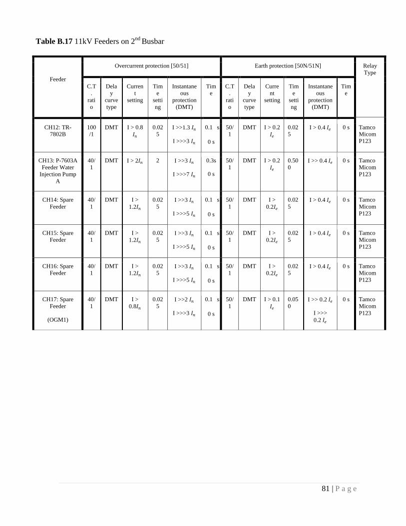
81 | P a g e
Table B.17 11kV Feeders on 2nd
Busbar
Feeder
Overcurrent protection [50/51] Earth protection [50N/51N] Relay
Type
C.T
.
rati
o
Dela
y
curve
type
Curren
t
setting
Tim
e
setti
ng
Instantane
ous
protection
(DMT)
Tim
e
C.T
.
rati
o
Dela
y
curve
type
Curre
nt
setting
Tim
e
setti
ng
Instantane
ous
protection
(DMT)
Tim
e
CH12: TR-
7802B
100
/1
DMT I > 0.8
𝐼𝑛
0.02
5 I >>1.3 𝐼𝑛
I >>>3 𝐼𝑛
0.1 s
0 s
50/
1
DMT I > 0.2
𝐼𝑒
0.02
5 I > 0.4 𝐼𝑒 0 s Tamco
Micom
P123
CH13: P-7603A
Feeder Water
Injection Pump
A
40/
1
DMT I > 2𝐼𝑛 2 I >>3 𝐼𝑛
I >>>7 𝐼𝑛
0.3s
0 s
50/
1
DMT I > 0.2
𝐼𝑒
0.50
0 I >> 0.4 𝐼𝑒 0 s Tamco
Micom
P123
CH14: Spare
Feeder
40/
1
DMT I >
1.2𝐼𝑛
0.02
5 I >>3 𝐼𝑛
I >>>5 𝐼𝑛
0.1 s
0 s
50/
1
DMT I >
0.2𝐼𝑒
0.02
5 I > 0.4 𝐼𝑒 0 s Tamco
Micom
P123
CH15: Spare
Feeder
40/
1
DMT I >
1.2𝐼𝑛
0.02
5 I >>3 𝐼𝑛
I >>>5 𝐼𝑛
0.1 s
0 s
50/
1
DMT I >
0.2𝐼𝑒
0.02
5 I > 0.4 𝐼𝑒 0 s Tamco
Micom
P123
CH16: Spare
Feeder
40/
1
DMT I >
1.2𝐼𝑛
0.02
5 I >>3 𝐼𝑛
I >>>5 𝐼𝑛
0.1 s
0 s
50/
1
DMT I >
0.2𝐼𝑒
0.02
5 I > 0.4 𝐼𝑒 0 s Tamco
Micom
P123
CH17: Spare
Feeder
(OGM1)
40/
1
DMT I >
0.8𝐼𝑛
0.02
5 I >>2 𝐼𝑛
I >>>3 𝐼𝑛
0.1 s
0 s
50/
1
DMT I > 0.1
𝐼𝑒
0.05
0 I >> 0.2 𝐼𝑒
I >>>
0.2 𝐼𝑒
0 s Tamco
Micom
P123

82 | P a g e
Incomer Overcurrent protection [50/51] Earth protection [50N/51N] Relay
Type
C.T.
ratio
Delay
curve
type
Current
setting
Time
setting
Instantaneous
protection
(DMT)
Time C.T.
ratio
Delay
curve
type
Current
setting
Time
setting
Instantaneous
protection
(DMT)
Time
CH07:
1#
Incomer
150/1 Disabled 150/1 Disabled Tamco
Micom
P121
CH07:
2#
Incomer
150/1 Disabled 150/1 Disabled Tamco
Micom
P121
Table B. 18 11kV Incomers
Table B. 19 33kV Transformer Feeders
Transformer
feeders
Overcurrent protection [50/51] Earth protection [50N/51N] Relay
Type C.T.
ratio
Delay
curve
type
Current
setting
Time
setting
Instantaneous
protection
(DMT)
Time C.T.
ratio
Delay
curve
type
Current
setting
Time
setting
Instantaneous
protection
(DMT)
Time
2#
Transformer
(TR 7801A)
75/1 DMT I >
0.6𝐼𝑛
0.1 Disabled 50/1 DMT I >
0.4𝐼𝑒
0.025 Disabled Schneider
P142
2#
Transformer
(TR 7801B)
75/1 DMT I >
0.6𝐼𝑛
0.1 Disabled 50/1 DMT I > 0.4
𝐼𝑒
0.025 Disabled Schneider
P142

83 | P a g e
Table B. 20 33kV Bus coupler
Bus
Coupler
Overcurrent protection [50/51] Earth protection [50N/51N] Relay
Type C.T.
ratio
Delay
curve
type
Current
setting
Time
setting
Instantaneous
protection
(DMT)
Time C.T.
ratio
Delay
curve
type
Current
setting
Time
setting
Instantaneous
protection
(DMT)
Time
Bus
coupler
150/1 DMT I >
0.4 𝐼𝑛
0.125 Disabled 150/1 Disabled Disabled Schneider
P143
Table B. 21 33kV Incomers
Incomer Overcurrent protection [50/51] Earth protection [50N/51N] Relay
Type
C.T.
ratio
Delay
curve type
Current
setting
Time
setting
Instantaneous
protection (DMT)
Time C.T.
ratio
Delay
curve type
Current
setting
Time
setting
Instantaneous
protection (DMT)
Time
CH07: 1#
Incomer
100/1 DMT I >
0.75𝐼𝑛
0.15 Disabled 50/1 DMT I >
1.14𝐼𝑒
0.15 Disabled Schneider
P143
CH07: 2# Incomer
100/1 DMT I >
0.75𝐼𝑛
0.15 Disabled 50/1 DMT I
>1.14𝐼𝑒
0.15 Disabled Schneider P143

84 | P a g e
Table B. 22 11 kV Bus-section & 11kV Two Incomers Directional Protection [the directional
Element is disabled = non-directional]
Incomer Overcurrent protection [67] Earth protection [67N] Relay
Type
C.T.
ratio
Delay
curve
type
Current
setting
Time
setting
Instantaneous
protection
(DMT)
Time C.T.
ratio
Delay
curve
type
Current
setting
Time
setting
Instantaneous
protection
(DMT)
Time
CH07:
1#
Incomer
150/1 DMT I
>0.9𝐼𝑛
0.075 Disabled 30/1 DMT I
>1.0𝐼𝑒
0.1 Disabled Tamco
P127
CH10:
2#
Incomer
150/1 DMT I
>0.9𝐼𝑛
0.075 Disabled 30/1 DMT I >
1.0 𝐼𝑒
0.1 Disabled Tamco
P127
CH08:
Bus
section
200/1 DMT I
>0.5𝐼𝑛
0.05 Disabled 200/1 Disabled Tamco
P127

85 | P a g e
B.4 OLD SETTINGS – KEYI SUBSTATION
Table B. 23 11kV Feeders on 1st
Busbar
Feeder
Overcurrent protection [50/51] Earth protection [50N/51N] Relay Type
C.T.
ratio
Delay
curve
type
Current
setting
Time
setting
Instantaneous
protection
(DMT)
Time C.T.
ratio
Delay
curve
type
Current
setting
Time
setting
Instantaneous
protection
(DMT)
Time
DH01: K13
RMU
40/1 DMT I >
0.5𝐼𝑛
0.200 I >>0.9𝐼𝑛
I >>>1.2𝐼𝑛
0 s
0 s
50/1 DMT I > 0.1
𝐼𝑒
0.05 I >>0.2 𝐼𝑒 0 s
Tamco
Micom P123
DH02:
OGM1 +
CAMP + Unloading
Pumps
100/1 DMT I >
0.3𝐼𝑛
0.200 I >>0.5 𝐼𝑛
I >>>0.5 𝐼𝑛
0 s
0 s
50/1 DMT I > 0.1
𝐼𝑒
0 I >>0.2 𝐼𝑒
0 s Tamco
Micom
P123
DH03: P-
6603C Feeder
Water
injection
Pump C
40/1 DMT I >
1.2𝐼𝑛
0.200 I >>2.1 𝐼𝑛
I >>>3 𝐼𝑛
0.1 s
0 s
50/1 IDMT
SI
I > 0.2
𝐼𝑒
0.500 I >> 0.4 𝐼𝑒 0 s Tamco
Micom P123
DH04: P-
7603B Feeder
Water
injection Pump B
40/1 DMT I >1.2
𝐼𝑛
0.200 I >>2.1 𝐼𝑛
I >>>3 𝐼𝑛
0 s
0 s
50/1 DMT I > 0.2
𝐼𝑒
0.500 I >> 0.4 𝐼𝑒
0 s Tamco
Micom P123
DH05: TR-7802A
100/1 DMT I >
0.5 𝐼𝑛
0.200 I>>0.79 𝐼𝑛
I>>>4.49 𝐼𝑛
0.3 s
0 s
50/1 DMT I >
0.2 𝐼𝑒
0.500 I >> 0.4 𝐼𝑒 0 s Tamco Micom
P123

86 | P a g e
Table B. 24 11kV Feeders on 2nd
Busbar
Feeder
Overcurrent protection [50/51] Earth protection [50N/51N] Relay
Type
C.T.
ratio
Dela
y
curv
e
type
Curren
t
setting
Tim
e
setti
ng
Instanta
neous
protecti
on
(DMT)
Time C
.
T
.
ra
ti
o
Dela
y
curve
type
Curren
t
setting
Tim
e
setti
ng
Instanta
neous
protectio
n
(DMT)
Tim
e
DH12: TR-6802B 100/
1
DM
T
I >
0.5𝐼𝑛
0.2 I>>0.84 𝐼𝑛
I>>>4.49 𝐼𝑛
3 s
0 s
5
0/
1
DMT I >
0.2𝐼𝑒
0.50
0
I >>
0.4 𝐼𝑒
0 s Tamco
Micom
P123
DH13: P-6603A
Feeder Water
injection Pump A
40/1 DM
T
I
>1.2𝐼𝑛
0.02
5 I>>2. 1 𝐼𝑛
I>>>3 𝐼𝑛
0.1 s
0 s
5
0/
1
DMT I > 0.2
𝐼𝑒
0.02
5
I >>
0.4 𝐼𝑒
0 s Tamco
Micom
P123
DH14: Fire Fighter
Pump
40/1 DM
T
I >
1.2 𝐼𝑛
4 I>>5 𝐼𝑛
I>>>7 𝐼𝑛
0.
3
s
5
0/
1
DMT I >
0.2 𝐼𝑒
0.50
0
I >>
0.4 𝐼𝑒
0 s Tamco
Micom
P123
DH15: OGM 2-3-
4-5
100/
1
DM
T
I
>0.3 𝐼𝑛
0.2 I>>0.5 𝐼𝑛
I>>>0.5 𝐼𝑛
0 s
0 s
5
0/
1
DMT I >
0.1 𝐼𝑒
0.05 I >>
0.2 𝐼𝑒
0 s Tamco
Micom
P123
DH16: Spare
Feeder (Perkins)
40/1 DM
T
I
>1.24
𝐼𝑛
0.02
5 I>>2 𝐼𝑛
I>>>3 𝐼𝑛
0.1 s
0 s
5
0/
1
DMT I >
0.2𝐼𝑒
0.02
5
I >
0.4 𝐼𝑒
0 s Tamco
Micom
P123

87 | P a g e
Incomer Overcurrent protection [50/51] Earth protection [50N/51N] Relay
Type
C.T.
rati
o
Delay
curve
type
Curre
nt
settin
g
Tim
e
setti
ng
Instantaneo
us
protection
(DMT)
Tim
e
C.T.
rati
o
Delay
curve
type
Current
setting
Tim
e
setti
ng
Instantaneous
protection
(DMT)
Time
DH07: 1#
Incomer
150/
1
DMT I>1.0
0𝐼𝑛
2 I>>2. 𝐼𝑛
I>>>3.5 𝐼𝑛
600
ms
0
ms
150/
1
DMT I >
0.15 𝐼𝑒
1.15 I >> 0.2 𝐼𝑒
0.6 s
Tamco
Micom
P121
DH11: 2#
Incomer
150/
1
DMT I>1.0
0𝐼𝑛
2 I>>2. 𝐼𝑛
I>>>3.5 𝐼𝑛
600
ms
0
ms
150/
1
DMT I >
0.15 𝐼𝑒
1.15 I >> 0.2 𝐼𝑒
0.6 s
Tamco
Micom
P121
Table B. 25 11kV Incomers
Table B. 26 33kV Transformer Feeders
Transformer
feeders
Overcurrent protection [50/51] Earth protection [50N/51N] Relay
Type C.T.
ratio
Delay
curve
type
Current
setting
Time
setting
Instantaneous
protection
(DMT)
Time C.T.
ratio
Delay
curve
type
Current
setting
Time
setting
Instantaneous
protection
(DMT)
Time
2#
Transformer
(TR-6801A)
75/1 DMT I >
0.6 𝐼𝑛
0.1 Disabled 50/1 DMT I >
0.3 𝐼𝑒
0.12 Disabled Schneider
P142
9#
Transformer
(TR-6801B)
75/1 DMT I >
0.6𝐼𝑛
0.1 Disabled 50/1 DMT I >
0.3 𝐼𝑒
0.12 Disabled Schneider
P142

88 | P a g e
Table B. 27 33kV Bus coupler
Bus
Coupler
Overcurrent protection [50/51] Earth protection [50N/51N] Relay
Type C.T.
ratio
Delay
curve
type
Current
setting
Time
setting
Instantaneous
protection
(DMT)
Time C.T.
ratio
Delay
curve
type
Current
setting
Time
setting
Instantaneous
protection
(DMT)
Time
6# Bus
coupler
150/1 DMT I
>0.4𝐼𝑛
0.125 Disabled 150/1 DMT I >
0.1 𝐼𝑒
0.02 s Disabled Schneider
P143
Table B. 28 33kV Incomers
Incomer Overcurrent protection [50/51] Earth protection [50N/51N] Relay
Type
C.T.
ratio
Delay
curve
type
Curren
t
setting
Time
settin
g
Instantane
ous
protection
(DMT)
Tim
e
C.T.
ratio
Delay
curve
type
Curren
t
setting
Time
setting
Instantaneous
protection
(DMT)
Time
4# Incoming
1
150/
1
DMT I >
0.5𝐼𝑛
0.15 Disabled 50/1 DMT I >
0.9𝐼𝑒
0.8 Disabled Schneider
P143
7# Incoming
2
150/
1
DMT I >
0.5 𝐼𝑛
0.15 Disabled 50/1 DMT I >
0.9𝐼𝑒
0.8 Disabled Schneider
P143

89 | P a g e
Incomer Overcurrent protection [67] Earth protection [67N] Relay
Type
C.T.
ratio
Dela
y
curv
e
type
Curren
t
setting
Tim
e
setti
ng
Instantane
ous
protection
(DMT)
Tim
e
C.T.
ratio
Delay
curve
type
Current
setting
Time
setting
Instantaneous
protection
(DMT)
Time
DH07: 1#
Incomer
150/
1
Disabled
Tamco
P127
DH10: 2#
Incomer
150/
1
Disabled
Tamco
P127
DH08: Bus
coupler
A/B
150/
1
DM
T
I
>0.9 𝐼𝑛
0.20 Disabled
Tamco
P127
Table B. 29 11kV Bus-section & 11kV Two Incomers Directional Protection [the
directional Element is disabled = non-directional]

90 | P a g e
B.5 OLD SETTINGS – CPF SUBSTATION
Table B. 30 11kV Substation Feeders
Feeder
Overcurrent protection [50/51] Earth protection [50N/51N] Relay
Type
C.T.
ratio
Delay
curve
type
Current
setting
Tim
e
setti
ng
Instantaneou
s protection
(DMT)
Ti
me
C.T.
ratio
Delay
curve
type
Current
setting
Time
setti
ng
Instantane
ous
protection
(DMT)
Ti
me
01: TR-1803A 100/
5
DMT I >
0.85𝐼𝑛
0.50
0 I >>2𝐼𝑛
I >>> 3.8 𝐼𝑛
0.1
s
0s
50/5 DMT I
>0.25𝐼𝑒
0.1 s I >>0.5𝐼𝑒
I >>> 1 𝐼𝑒
0.1
s
0s
Alstom
Micom
P123
04: TR-1805A 100/
5
DMT I > 1 𝐼𝑛 0.50
0 I >> 2 𝐼𝑛
I >>> 4 𝐼𝑛
0.1
s
0s
100/
5
DMT I >
0.125𝐼𝑒
0.50
0 I >>0.25𝐼𝑒
I >>> 0.5
𝐼𝑒
0.1
s
0s
Alstom
Micom
P122
10: TR-1801B 100/
5
DMT I > 1 𝐼𝑛 0.50
0 I >> 2 𝐼𝑛
I >>> 4 𝐼𝑛
0.1
s
0s
100/
5
DMT I >
0.125 𝐼𝑒
0.50
0
I
>>0.25 𝐼𝑒
I >>> 0.5
𝐼𝑒
0.1
s
0s
Alstom
Micom
P122
13: TR-1801C 100/
5
DMT I >1.5
𝐼𝑛
0.3 I >> 3 𝐼𝑛
I >>> 6 𝐼𝑛
0.1
s
0s
50/5 DMT I >.4𝐼𝑒 0.07
5 I >>0.6𝐼𝑒
I >>> 1.2
𝐼𝑒
0.1
s
0s
AREVA
MicomP
122
13: TR-1803B 100/
5
DMT I >1𝐼𝑛 0.50
0 I >> 2 𝐼𝑛
I >>> 4 𝐼𝑛
0.1
s
0s
50/5 DMT I
>0.25𝐼𝑒
0.50
0 I >>0.5𝐼𝑒
I >>> 1 𝐼𝑒
0.1
s
0s
Alstom
Micom
P123
15: Initial
substation -2
100/
5
DMT I > 3𝐼𝑛 0.510 I >> 6 𝐼𝑛
I >>> NO
0.1
s
0s
50/5
DMT
I
>0.67
𝐼𝑒
0.075 I>>1.3
𝐼𝑒
I >>>
NO
0.1s
Alstom
Micom
P122
16: RMU-2 200/ DMT I > 0.8 1.00 I >> 1.25 𝐼𝑛 0.3 200/ DMT I > 0.30 I >>0.2𝐼𝑒 0.1 Alstom
Micom

91 | P a g e
5 𝐼𝑛 I >>> 2 𝐼𝑛 s
0s
5 0.1𝐼𝑒 0 I >>> 0.3
𝐼𝑒
s
0s
P123
18: FULA
CENTRE -1-1
& 1-2
200/
5
DMT
I > 0.8
𝐼𝑛
2.00 I >> 1.25 𝐼𝑛
I >>>2 𝐼𝑛
0.1
s
0.1
s
50/5 DMT I > 0.25
𝐼𝑒
0.30
0 I >> 0.4𝐼𝑒
I
>>>0.8𝐼𝑒
0.1
s
0s
Alstom
Micom
P123
19: RMU-1 200/
5
DMT I > 0.8
𝐼𝑛
1.00 I >> 1.25 𝐼𝑛
I >>> 2 𝐼𝑛
0.3
s
0s
200/
5
DMT I >
0.1𝐼𝑒
0.30
0 I >>0.2 𝐼𝑒
I >>> 0. 𝐼𝑒
0.1
s
0s
Alstom
Micom
P123
19: TR-1801E 100/
5
DMT I > 0.8
𝐼𝑛
0.07
5 I >> 2 𝐼𝑛
I >>>4 In
I >>> 4 𝐼𝑛
0.1
s
0s
50/5 DMT I > 0.25
𝐼𝑒
0.07
5 I >>0.5𝐼𝑒
I >>> 1 𝐼𝑒
0.1
s
0s
AREVA
MicomP
122
15: Initial
substation -2
The relay is not working and the switchgear is OFF
TR-1801F 100/
1
DMT I > 0.8
𝐼𝑛
0.07
5 I >> 2 𝐼𝑛
I >>> 4 𝐼𝑛
0.1
s
0s
50/1 DMT I >
0.25𝐼𝑒
0.07
5 I >>0.5𝐼𝑒
I >>> 1 𝐼𝑒
0.1
s
0s
AREVA
Micom
P122
TR-1801D 100/
1
DMT I > 1.5
𝐼𝑛
0.3 I >> 3 𝐼𝑛
I >>> 6 𝐼𝑛
0.1
s
0s
50/1 DMT I > 0.4 𝐼𝑒 0.07
5 I >>0.6𝐼𝑒
I >>> 1.2
𝐼𝑒
0.1
s
0s
AREVA
Micom
P122

92 | P a g e
Table B. 31 11Kv Substation New Added Feeders
Feeder
Overcurrent protection [50/51] Earth protection [50N/51N] Relay
Type
C.T
.
rati
o
Del
ay
cur
ve
type
Current
setting
Tim
e
setti
ng
Instantaneo
us
protection
(DMT)
Ti
me
C.T.
rati
o
Dela
y
curv
e
type
Current
setting
Tim
e
setti
ng
Instantane
ous
protection
(DMT)
Ti
me
01: Spare Feeder 200
/1
DM
T
I
>0.73
𝐼𝑛
0.07
5 I >>1.5𝐼𝑛
0.1
s
50/1 DM
T
I >0.25
𝐼𝑒
0.07
5 I >>0.8𝐼𝑒 0.1
s
Tamco
Micom
P141
02: Spare Feeder 300
/1
DM
T
I > 0.73
𝐼𝑛
0.07
5 I >> 1.2 𝐼𝑛
I >>> 7.4 𝐼𝑛
0.1
s
0.1
s
50/1 DM
T
I > 0.25
𝐼𝑒
0.07
5 I >> 0.5 𝐼𝑒 0.1
s
Tamco
Micom
P142
04: TR-1807A
(AGR)
150
/1
DM
T
I >0.65
𝐼𝑛
0.07
5 I >>2𝐼𝑛
0.1
s
50/1 DM
T
I > 0.25
𝐼𝑒
0.07
5 I >>0.5 𝐼𝑒 0.1
s
Tamco
Micom
P142
05: Spare Feeder 300
/1
DM
T
I > 0.73
𝐼𝑛
0.07
5 I >> 1 𝐼𝑛
0.1
s
50/1 DM
T
I > 0.25
𝐼𝑒
0.07
5 I >> 0.5 𝐼𝑒 0.1
s
Tamco
Micom
P142
06: WIP Pump
1605A
75/
1
DM
T
I
>2.5𝐼𝑛
0.07
5 I >>4𝐼𝑛
0.1
s
50/1 DM
T
I >0.25
𝐼𝑒
0.07
5 I >>0.5 𝐼𝑒 0.1
s
Tamco
Micom
P142
07: WIP Pump
1605B
75/
1
DM
T
I
>2.5𝐼𝑛
0.07
5 I >>4𝐼𝑛
0.1
s
50/1 DM
T
I >0.25
𝐼𝑒
0.07
5
I >> 0.5 𝐼𝑒 0.1
s
Tamco
Micom
P142
08: Spare Feeder 300
/1
DM
T
I > 0.5
𝐼𝑛
0.07
5 I >>1 𝐼𝑛
0.1
s
50/1 DM
T
I > 0.25
𝐼𝑒
0.07
5 I >> 0.5 𝐼𝑒 0 s Tamco
Micom
P141
09: Spare Feeder
(PSI-2 Incoming
Line)
400
/1
DM
T
I >1.25
𝐼𝑛
0.07
5 I >> 1.4 𝐼𝑛
I >>> 1.6 𝐼𝑛
0.1
s
0s
50/1 DM
T
I > 0.25
𝐼𝑒
0.07
5
I >> 0.5 𝐼𝑒 0 s Tamco
Micom
P142
16: Spare Feeder 300
/1
DM
T
I > 0.73
𝐼𝑛
0.07
5 I >> 1.5𝐼𝑛
0.1
s
50/1 DM
T
I > 0.25
𝐼𝑒
0.07
5 I >> 0.5 𝐼𝑒 0 s Tamco
Micom
P142

93 | P a g e
17: Spare Feeder 300
/1
DM
T
I > 0.73
𝐼𝑛
0.07
5 I >> 1 𝐼𝑛 50/1 DM
T
I > 0.25
𝐼𝑒
0.07
5 I >> 0.5 𝐼𝑒 0.1
s
Tamco
Micom
P141
19: TR-1807B 150
/1
DM
T
I > 0.65
𝐼𝑛
0.07
5 I >> 2 𝐼𝑛
0.1
s
50/1 DM
T
I > 0.25
𝐼𝑒
0.07
5 I >>0.5 𝐼𝑒 0.1
s
Tamco
Micom
P142
20: Spare Feeder 300
/1
DM
T
I > 0.73
𝐼𝑛
0.07
5 I >> 1.08𝐼𝑛
0.1
s
50/1 DM
T
I > 0.25
𝐼𝑒
0.07
5 I >> 0.5 𝐼𝑒 0 s Tamco
Micom
P142
21: Spare Feeder 200
/1
DM
T
I > 0.73
𝐼𝑛
0.07
5 I >> 1.5𝐼𝑛
0.1
s
50/1 DM
T
I > 0.25
𝐼𝑒
0.07
5 I >> 0.5 𝐼𝑒 0s Tamco
Micom
P141
22: WIP Pump
1605C
75/
1
DM
T
I
>2.5𝐼𝑛
0.07
5 I >> 4𝐼𝑛
0.1
s
50/1 DM
T
I >0.25
𝐼𝑒
0.07
5 I >> 0.5 𝐼𝑒 0.1
s
Tamco
Micom
P142
23: Spare Feeder 100
/1
DM
T
I > 0.73
𝐼𝑛
0.07
5 I >> 1.08𝐼𝑛
0.1
s
50/1 DM
T
I > 0.25
𝐼𝑒
0.07
5
I >> 0.5 𝐼𝑒 0.1
s
Tamco
Micom
P142
24: Spare Feeder
(PSI-1 Incoming
Line)
400
/1
DM
T
I > 1.25
𝐼𝑛
0.07
5 I >> 1.4 𝐼𝑛
I >>> 1.6 𝐼𝑛
0.1
s
0s
50/1 DM
T
I > 0.25
𝐼𝑒
0.07
5 I >> 0.5 𝐼𝑒 0.1
s
Tamco
Micom
P142

94 | P a g e
Table B. 32 11 kV Bus-section & 11 kV Transformer feeders
Incomer Overcurrent protection [67] Earth protection [67N] Relay
Type
C.T.
ratio
Delay
curve
type
Current
setting
Time
setting
Instantaneous
protection
(DMT)
Time C.T.
ratio
Delay
curve
type
Current
setting
Time
setting
Instantaneous
protection
(DMT)
Time
03:
Transformer
(TR-1806A)
800/1 DMT I >
0.66𝐼𝑛
0.275 Disabled 50/1 DMT I >1 𝐼𝑒 0.025 Disabled Tamco
Micom
P142
18:
Transformer
(TR-1806A)
800/1 DMT I >
0.66𝐼𝑛
0.275 Disabled 50/1 DMT I > 1 𝐼𝑒 0.025 Disabled Tamco
Micom
P142
DH08: Bus
section
1500/1 DMT I >
0.36𝐼𝑛
0.3 Disabled 50/1 Disabled Tamco
Micom
P143
Table B. 33 33 kV Transformer
Feeders
Transformer
feeders
Overcurrent protection [50/51] Earth protection [50N/51N] Relay
Type
C.T.
ratio
Delay
curve
type
Current
setting
Time
setting
Instantaneous
protection
(DMT)
Time C.T.
ratio
Delay
curve
type
Current
setting
Time
setting
Instantaneous
protection
(DMT)
Time
H8: Transformer
(TR-1806A)
250/1 Disabled 75/1 Disabled AREVA
P121
250/1 DMT I
>0.7𝐼𝑛
0.25 Disabled 250/1 DMT I >
0.31𝐼𝑒
0.275 Disabled AREVA
P142
H11:Transformer
( TR-1806B )
250/1 Disabled 75/1 Disabled AREVA
P121
250/1 DMT I
>0.7 𝐼𝑛
0.25 Disabled 250/1 DMT I > 0.31
𝐼𝑒
0.275 Disabled AREVA
P142

95 | P a g e
Table B. 34 11 kV Bus-section & 11 kV Transformer
feeders
Incomer Overcurrent protection [67] Earth protection [67N] Relay
Type
C.T.
ratio
Delay
curve
type
Current
setting
Time
setting
Instantaneous
protection
(DMT)
Time C.T.
ratio
Delay
curve
type
Current
setting
Time
setting
Instantaneous
protection
(DMT)
Time
03:
Transformer
(TR-1806A)
800/1 DMT I >
0.66𝐼𝑛
0.275 Disabled 50/1 DMT I >1 𝐼𝑒 0.025 Disabled Tamco
Micom
P142
18:
Transformer
(TR-1806A)
800/1 DMT I >
0.66𝐼𝑛
0.275 Disabled 50/1 DMT I > 1 𝐼𝑒 0.025 Disabled Tamco
Micom
P142
DH08: Bus
section
1500/1 DMT I >
0.36𝐼𝑛
0.3 Disabled 50/1 Disabled Tamco
Micom
P143
Table B. 35 33 kV Transformer
Feeders
Transformer
feeders
Overcurrent protection [50/51] Earth protection [50N/51N] Relay
Type
C.T.
ratio
Delay
curve
type
Current
setting
Time
setting
Instantaneous
protection
(DMT)
Time C.T.
ratio
Delay
curve
type
Current
setting
Time
setting
Instantaneous
protection
(DMT)
Time
H8: Transformer
(TR-1806A)
250/1 Disabled 75/1 Disabled AREVA
P121
250/1 DMT I
>0.7𝐼𝑛
0.25 Disabled 250/1 DMT I >
0.31𝐼𝑒
0.275 Disabled AREVA
P142
H11:Transformer
( TR-1806B )
250/1 Disabled 75/1 Disabled AREVA
P121
250/1 DMT I
>0.7 𝐼𝑛
0.25 Disabled 250/1 DMT I > 0.31
𝐼𝑒
0.275 Disabled AREVA
P142

96 | P a g e
Table B. 36 33kVBustie
Item Overcurrent protection [50/51] Earth protection [50N/51N] Relay
Type C.T.
ratio
Delay
curve
type
Current
setting
Time
setting
Instantaneous
protection
(DMT)
Time C.T.
ratio
Delay
curve
type
Current
setting
Time
setting
Instantaneous
protection
(DMT)
Time
H9:
Bus
coupler
200/1 DMT I >
0.85𝐼𝑛
0.225 Disabled 200/1 Disabled Disabled AREVA
P143
Table B. 37 33 kV outgoings
Incomer Overcurrent protection [50/51] Earth protection [50N/51N] Relay
Type
C.T.
ratio
Dela
y
curve
type
Current
setting
Tim
e
setti
ng
Instantane
ous
protection
(DMT)
Tim
e
C.T.
ratio
Delay
curve
type
Current
setting
Time
settin
g
Instantaneous
protection
(DMT)
Time
H1: FNE 1 150/
1
DMT I >
0.5𝐼𝑛
0.17
5 I >> 4𝐼𝑛 0 s 50/1 DMT I >
1.14𝐼𝑒
0.175 Disabled Areva
P123
H3: KEYI 1 100/
1
DMT I > 0.75
𝐼𝑛
0.17
5 I >> 4𝐼𝑛 0 s 50/1 DMT I > 0.2𝐼𝑒 0.1 I > 0.25𝐼𝑒 0 s Areva
P123
H5: MOGA
1
150/
1
DMT I > 0.5
𝐼𝑛
0.22
5 I >> 4𝐼𝑛 0 s 50/1 DMT I >
1.32𝐼𝑒
0.225 Disabled Areva
P123
H15: KEYI
2
100/
1
DMT I > 0.75
𝐼𝑛
0.17
5 I >> 4𝐼𝑛 0 s 50/1 DMT I > 0.2𝐼𝑒 0.1 I > 0.25𝐼𝑒 0 s Areva
P123
H13:
MOGA 2
150/
1
DMT I > 0.5
𝐼𝑛
0.22
5 I >> 4𝐼𝑛 0 s 50/1 DMT I >
1.32𝐼𝑒
0.225 Disabled Areva
P123
H17: FNE 2 150/
1
DMT I > 0.5
𝐼𝑛
0.17
5 I >> 4𝐼𝑛 0 s 50/1 DMT I >
1.14𝐼𝑒
0.175 Disabled Areva
P123

97 | P a g e
8 Appendix C
9 NEW SETTING
C.1 NEW RELAY COORDINATION SETTINGS – FNE
SUBSTATION
Feeder
Overcurrent protection [50/51] Earth protection [50N/51N] Relay
Type
C.T.
ratio
Delay
curve
type
Current
setting
Time
setting
Instantaneous
protection
(DMT)
Time C.T.
ratio
Delay
curve
type
Current
setting
Time
setting
Instantaneous
protection
(DMT)
Time
BH01: Spare Feeder 40/1 IDMT
SI
Disabled 50/1 IDMT
SI
Disabled Tamco
Micom
P123
BH02: Spare Feeder 150/1 IDMT
SI
Disabled 50/1 IDMT
SI
Disabled Tamco
Micom
P123
BH03: Spare Feeder 150/1 IDMT
SI
Disabled 50/1 IDMT
SI
Disabled Tamco
Micom
P123
BH04: 1# RMUFeeder
150/1 IDMT SI
I >0.5𝐼𝑛 0.025 I >>1𝐼𝑛
0s
50/1 IDMT SI
I > 0.1
𝐼𝑒
0.025 I >> 0.2 𝐼𝑒 0s Tamco
Micom
P123
BH05: TR-8802A 100/1 IDMT
SI
I > 0.2
𝐼𝑛
0.025 I >>0.5𝐼𝑛
0s
50/1 IDMT
SI
I >
0.4𝐼𝑒
0.025 I >>0.8𝐼𝑒 0s Tamco
Micom
P123
Table C.1 11kV FEEDERS on 1st Busbar

98 | P a g e
Feeder
Overcurrent protection [50/51] Earth protection [50N/51N] Relay Type
C.T.
ratio
Dela
y curv
e
type
Current
setting
Time
setting
Instantaneous
protection (DMT)
Time C.T.
ratio
Delay
curve type
Current
setting
Time
setting
Instantaneou
s protection (DMT)
Tim
e
BH12: TR-8802B 100/1
IDMT SI
I > 2.5
𝐼𝑛
0.025 I >> 5 𝐼𝑛 0s 50/1 IDMT SI
I >
0.35𝐼𝑒
0.025 I >>0.7𝐼𝑒 0s Tamco Micom
P123
BH13: Spare Feeder 100/
1
IDM
TSI
Disabled 50/1 IDM
T SI
Disabled Tamco
Micom P123
BH14: Spare Feeder 40/1 IDM SI
Disabled 50/1 IDMT SI
Disabled Tamco Micom
P123
BH15: 1# RMU
Feeder
150/
1
IDM
TSI
Disabled 50/1 IDM
T SI
Disabled Tamco
Micom
P123
BH16: Spare Feeder 100/
1
IDM
TSI
Disabled 50/1 IDM
T SI
Disabled Tamco
Micom
P123
Table C.2 11kV FEEDERS on 2nd
Busbar
Incomer Overcurrent protection [50/51] Earth protection [50N/51N] Relay
Type
C.T. ratio
Delay curve
type
Current setting
Time setting
Instantaneous protection
(DMT)
Time C.T. ratio
Delay curve
type
Current setting
Time setting
Instantaneous protection
(DMT)
Time
BH07: 1# Incomer
200/1 IDMT SI
I >
1.65𝐼𝑛
0.075 Disabled 200/1 IDMT SI
I > 0.3𝐼𝑒 0.15 Disabled Tamco Micom
P121
BH10: 2#
Incomer
200/1 IDMT
SI
I >
1.65𝐼𝑛
0.075 Disabled 200/1 IDMT
SI I > 0.3𝐼𝑒 0.15 Disabled Tamco
Micom P121
Table C.3 11kV incomers

99 | P a g e
Table C.4 33kV Transformer Feeders
Transformer
feeders
Overcurrent protection [50/51] Earth protection [50N/51N] Relay Type
C.T. ratio
Delay curve
type
Current setting
Time setting
Instantaneous protection
(DMT)
Time C.T. ratio
Delay curve
type
Current setting
Time setting
Instantaneous protection
(DMT)
Time
2# TR-A 75/1 IDMT
SI
I >
1.6𝐼𝑛
0.075 I >> 9 𝐼𝑛 0s 50/1 IDMT
SI
I >
0.35𝐼𝑒
0.025 I >> 1.05𝐼𝑛 0 Schneider
P142
9# TR-B 75/1 IDMT
SI
I >
1.6𝐼𝑛
0.075 I >> 9 𝐼𝑛 0s 50/1 IDMT
SI
I >
0.35𝐼𝑒
0.075 I >> 1.05𝐼𝑛 0 Schneider
P142
Table C.5 33kV Bus coupler
Bus Coupler Overcurrent protection [50/51] Earth protection [50N/51N] Relay Type
C.T. ratio
Delay curve
type
Current setting
Time setting
Instantaneous protection
(DMT)
Time C.T. ratio
Delay curve
type
Current setting
Time setting
Instantaneous protection
(DMT)
Time
6# Bus
coupler
150/1 IDMT
SI
I >
0.95𝐼𝑛
0.1 Disabled 150/1 IDMT
SI
I >
0.15𝐼𝑛
0.075 Disabled Schneider
P143
Table C.6 33kV incomers
Incomer Overcurrent protection [50/51] Earth protection [50N/51N] Relay
Type C.T. ratio
Delay curve
type
Current setting
Time setting
Instantaneous protection
(DMT)
Time C.T. ratio
Delay curve
type
Current setting
Time setting
Instantaneous protection
(DMT)
Time
4# Incoming
1
150/1 IDMT
SI I >1 𝐼𝑛 0.15 Disabled 50/1 IDMT
SI
I >
0.5𝐼𝑒
0.15 Disabled Schneider
P143
7# Incoming
2
150/1 IDMT
SI I >1 𝐼𝑛 0.15 Disabled 50/1 IDMT
SI
I >
0.5𝐼𝑒
0.15 Disabled Schneider
P143

100 | P a g e
Table C.7 11kV Bus-section & 11kV two incomers Directional Protection
Incomer Overcurrent protection [67] Earth protection [67N] Relay
Type C.T.
ratio
Delay
curve
type
Current
setting
Time
setting
Instantaneous
protection
(DMT)
Time C.T.
ratio
Delay
curve
type
Current
setting
Time
setting
Instantaneous
protection
(DMT)
Time
BH07:
1#
Incomer
200/1 IDMT SI
Disabled 40/1 IDMT SI
Disabled Tamco
P127
BH10:
2#
Incomer
200/1 IDMT
SI
Disabled 40/1 IDMT
SI
Disabled Tamco
P127
BH08:
Bus
section
200/1 IDMT SI
I > 1.25
𝐼𝑛
0.05 Disabled 200/1 IDMT SI
I >
0.25𝐼𝑒
0.075 Disabled Tamco
P127
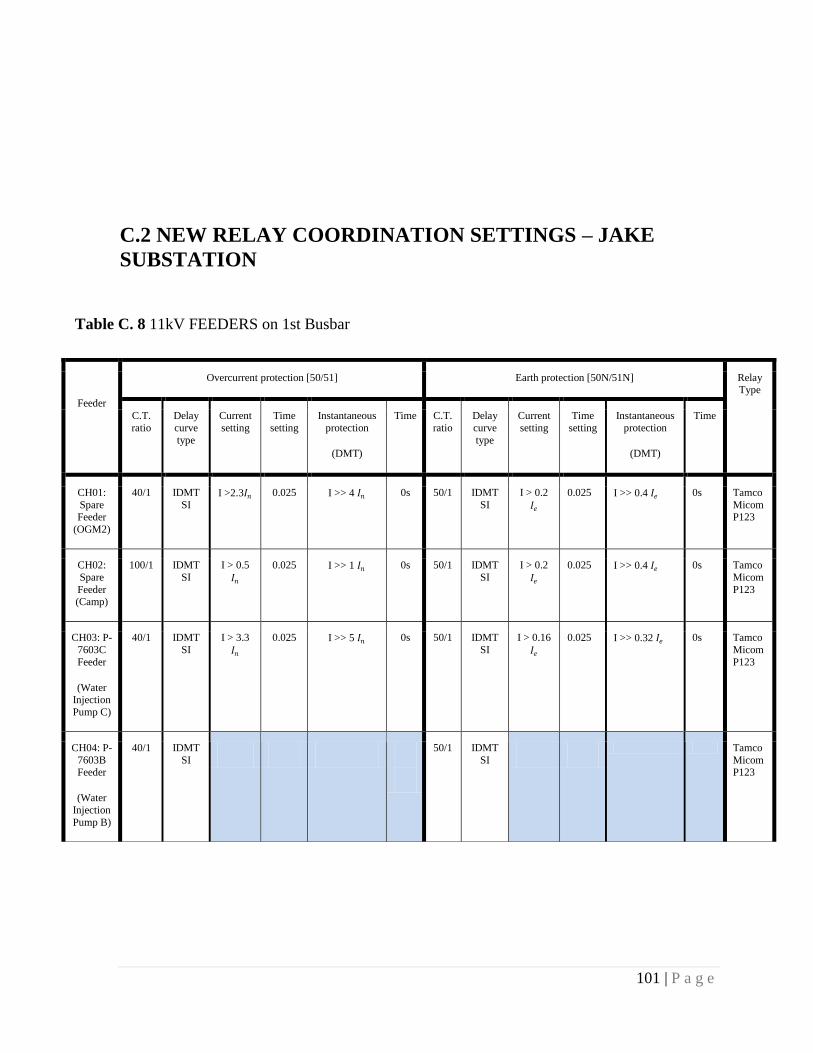
101 | P a g e
C.2 NEW RELAY COORDINATION SETTINGS – JAKE
SUBSTATION
Feeder
Overcurrent protection [50/51] Earth protection [50N/51N] Relay Type
C.T.
ratio
Delay
curve
type
Current
setting
Time
setting
Instantaneous
protection
(DMT)
Time C.T.
ratio
Delay
curve
type
Current
setting
Time
setting
Instantaneous
protection
(DMT)
Time
CH01:
Spare Feeder
(OGM2)
40/1 IDMT
SI I >2.3𝐼𝑛 0.025 I >> 4 𝐼𝑛
0s
50/1 IDMT
SI
I > 0.2
𝐼𝑒
0.025 I >> 0.4 𝐼𝑒 0s Tamco
Micom P123
CH02:
Spare
Feeder (Camp)
100/1 IDMT
SI
I > 0.5
𝐼𝑛
0.025 I >> 1 𝐼𝑛 0s
50/1 IDMT
SI
I > 0.2
𝐼𝑒
0.025 I >> 0.4 𝐼𝑒 0s Tamco
Micom
P123
CH03: P-
7603C
Feeder
(Water Injection
Pump C)
40/1 IDMT
SI
I > 3.3
𝐼𝑛
0.025 I >> 5 𝐼𝑛
0s
50/1 IDMT
SI
I > 0.16
𝐼𝑒
0.025 I >> 0.32 𝐼𝑒 0s Tamco
Micom
P123
CH04: P-
7603B Feeder
(Water
Injection
Pump B)
40/1 IDMT
SI
50/1 IDMT
SI
Tamco
Micom P123
Table C. 8 11kV FEEDERS on 1st Busbar

102 | P a g e
Table C. 9 11kV FEEDERS on 2nd Busbar
Feeder
Overcurrent protection [50/51] Earth protection [50N/51N] Relay
Type
C.T.
ratio
Dela
y curv
e
type
Current
setting
Time
setting
Instantaneous
protection (DMT)
Time C.T.
ratio
Delay
curve type
Current
setting
Time
setting
Instantaneou
s protection (DMT)
Time
CH05: TR-7802B 100/1
IDMT SI
I > 1 𝐼𝑛 0.025 I >> 2 𝐼𝑛 0s 0s
50/1 IDMT SI
I > 0.2
𝐼𝑒
Tamco
Micom
P123
CH04: P-7603A
Feeder (Water Injection Pump A)
CH14: Spare Feeder 40/1 IDM SI
I > 1.24
𝐼𝑛
0.025 I >> 20.21 𝐼𝑛 I
>>> 34.2 𝐼𝑛
0s 0s
50/1 IDMT SI
I > 0.8
𝐼𝑒
0.025 I >> 0.16 𝐼𝑒 0s Tamco
Micom
P123
CH15: Spare Feeder 40/1 IDMTSI
I > 1.24
𝐼𝑛
0.025 I >> 20.21 𝐼𝑛 I
>>> 34.2 𝐼𝑛
0s
0s
50/1 IDMT SI
I > 0.8
𝐼𝑒
0.025 I >> 0.16 𝐼𝑒 0s Tamco
Micom
P123
CH16: Spare Feeder 40/1 IDMTSI
I > 1.24
𝐼𝑛
0.025 I >> 20.21 𝐼𝑛
I >>> 34.2 𝐼𝑛
0s
0s
50/1 IDMT SI
I > 0.8
𝐼𝑒
0.025 I >> 0.16 𝐼𝑒 0s Tamco
Micom
P123
CH17: Spare Feeder
(OGM1)
40/1 IDM
T SI I >1.6𝐼𝑛 0.025 I >> 2.5 𝐼𝑛
0s
50/1 IDM
T SI I > 𝐼𝑒 0.025 I >> 0.4 𝐼𝑒 0s Tamco
Micom
P123

103 | P a g e
Table C.10 11kV incomers
Incomer Overcurrent protection [50/51] Earth protection [50N/51N] Relay
Type C.T.
ratio
Delay
curve
type
Current
setting
Time
setting
Instantaneous
protection
(DMT)
Time C.T.
ratio
Delay
curve
type
Current
setting
Time
setting
Instantaneous
protection
(DMT)
Time
CH07: 1#
Incomer
150/1 IDMT SI
I > 1 𝐼𝑛 0.1 Disabled 150/1 IDMT SI
I >
0.17𝐼𝑒
0.05 Disabled
Micom
P121
CH07: 2#
Incomer
150/1 IDMT SI
I > 1 𝐼𝑛 0.1 Disabled 150/1 IDMT SI
I >
0.17𝐼𝑒
0.05 Disabled Tamco
Micom
P121
Table C.11 33kV Transformer Feeders
Transformer
feeders
Overcurrent protection [50/51] Earth protection [50N/51N] Relay
Type
C.T.
ratio
Delay
curve
type
Current
setting
Time
setting
Instantaneous
protection
(DMT)
Time C.T.
ratio
Delay
curve
type
Current
setting
Time
setting
Instantaneous
protection
(DMT)
Time
2#
Transformer
(TR 7801A)
75/1 IDMT
SI
I >
0.8𝐼𝑛
0.8 s I >> 8𝐼𝑛 0s 50/1 IDMT
SI
I > 0.2
𝐼𝑒
0.075 I >> 0.4 𝐼𝑒
0.05s Schneider
P142
2#
Transformer
(TR 7801B)
75/1 IDMT
SI
I >
0.8𝐼𝑛
0.8 s I >> 8 𝐼𝑛 0s 50/1 IDMT
SI
I > 0.2
𝐼𝑒
0.075 I >> 0.4 𝐼𝑒 0.05s Schneider
P142

104 | P a g e
Table C. 12 33kV Bus coupler
Bus
Coupler
Overcurrent protection [50/51] Earth protection [50N/51N] Relay
Type
C.T.
ratio
Delay
curve
type
Current
setting
Time
setting
Instantaneous
protection
(DMT)
Time C.T.
ratio
Delay
curve
type
Current
setting
Time
setting
Instantaneous
protection
(DMT)
Time
Bus
coupler
150/1 IDMT
SI
I > 0.4
𝐼𝑛
0.15 Disabled Disabled Disabled Schneider
P143
Table C. 13 33kV Incomers
Incomer Overcurrent protection [50/51] Earth protection [50N/51N] Relay
Type
C.T. ratio
Delay curve
type
Current setting
Time setting
Instantaneous protection
(DMT)
Time C.T. ratio
Delay curve
type
Current setting
Time setting
Instantaneous protection
(DMT)
Time
CH07: 1#
Incomer
100/1 IDMT
SI
I > 0.75
𝐼𝑛
0.2 Disabled 50/1 IDMT
SI
I > 0.6
𝐼𝑒
0.125 I >>1𝐼𝑒 0.1s Schneider
P143
CH07: 2#
Incomer
100/1 IDMT
SI
I > 0.75
𝐼𝑛
0.2 Disabled 50/1 IDMT
SI
I > 0.6
𝐼𝑒
0.125 I >> 1 𝐼𝑒 0.1s Schneider
P143
Table C.14 11kV Bus-section & 11kV two incomers Directional Protection
Incomer Overcurrent protection [67] Earth protection [67N] Relay
Type
C.T.
ratio
Delay
curve type
Current
setting
Time
setting
Instantaneous
protection (DMT)
Time C.T.
ratio
Delay
curve type
Current
setting
Time
setting
Instantaneous
protection (DMT)
Time
CH07: 1#
Incomer
150/1 SI Disabled 30/1 IDMT
SI
I > 1.6
𝐼𝑒
0.05 Disabled Tamco
P127

105 | P a g e
C.3 NEW SETTINGS – KEYI SUBSTATION
CH10: 2#
Incomer
150/1 IDMT
SI
Disabled 30/1 IDMT
SI
I > 1.1
𝐼𝑒
0.05 Disabled Tamco
P127
CH08: Bus
section
200/1 IDMT
SI
I > 0.75
𝐼𝑛
0.05 Disabled 200/1 Disabled Tamco
P127
Table C. 15 11kV FEEDERS on 1st Busbar
Feeder
Overcurrent protection [50/51] Earth protection [50N/51N] Relay
Type
C.T.
ratio
Delay
curve type
Current
setting
Time
setting
Instantaneous
protection (DMT)
Time C.T.
ratio
Delay
curve type
Current
setting
Time
setting
Instantaneous
protection(DMT)
Time
DH01: Spare
Feeder (RMU)
40/1 IDMT
SI
I
>4.9𝐼𝑛
0.025 I >>9.8𝐼𝑛 0s
50/1 IDMT
SI
I >
0.25 𝐼𝑒
0.025 I >> 0.5 𝐼𝑒 0s Tamco
Micom P123
DH02: Spare
Feeder (OGM1 +
CAMP +
Unloading pumps)
100/1 IDMT
SI
I >
0.1𝐼𝑛
0.025 I >> 0.5𝐼𝑛 0s
50/1 IDMT
SI
I >
0.03 𝐼𝑒
0.025 I >> 0.06 𝐼𝑒 0s Tamco
Micom P123
DH03: P-
6603C
Feeder(Water injection
Pump C)
Disabled Disabled Tamco
Micom
P123
DH04: P-
7603B
Feeder(Water injection
Pump B)
disabled disabled Tamco
Micom
P123
DH05: TR-
7802A
100/1 IDMT
SI
I >
0.6𝐼𝑛
0.025 I >>1.2𝐼𝑛 0s
50/1 IDMT
SI
I >
0.08𝐼𝑒
0.025 I >>0.16𝐼𝑒 0s Tamco
Micom P123

106 | P a g e
Table C.16 11kV FEEDERS on 2nd Busbar
Feeder
Overcurrent protection [50/51] Earth protection [50N/51N] Relay
Type
C.T. ratio
Delay
curv
e type
Current setting
Time
setti
ng
Instantaneous protection
(DMT)
Time
C.T. ratio
Delay curve
type
Current setting
Time settin
g
Instantaneous protection
(DMT)
Time
DH12: TR-6802B 100/1 IDM
T SI I > 0.35𝐼𝑛 0.02
5 I >>0.7𝐼𝑛
0s
50/1 IDM
T SI
I >
0.05 𝐼𝑒
0.025 I >>0.1𝐼𝑒 0s Tamcos
Micom
P123
DH13: P-6603A Feeder
(Water injection Pump A)
40/1 IDM
TSI
Disabled 50/1 IDM
T SI
Disabled Tamco
Micom P123
DH14: Spare Feeder
(Fire Fighter)
40/1 IDM
SI
Disabled 50/1 IDM
T SI
Disabled Tamco
Micom
P123
DH15: Spare Feeder
(OGM)
100/1 IDM
TSI I >0.45𝐼𝑛 0.02
5 I >>0.9𝐼𝑛 0s
50/1 IDM
T SI
I >
0.1𝐼𝑒
0.025 I >> 0.2𝐼𝑒 0s Tamco
Micom
P123
DH16: Spare Feeder
(Perkins)
40/1 IDM
TSI
Disabled 50/1 IDM
T SI
Disabled Tamco
Micom
P123
Table C.17 11kV Incomers
Incomer Overcurrent protection [50/51] Earth protection [50N/51N] Relay
Type
C.T. ratio
Delay curve
type
Current setting
Time setting
Instantaneous protection
(DMT)
Time C.T. ratio
Delay curve
type
Current setting
Time setting
Instantaneous protection
(DMT)
Time
DH07: 1#
Incomer
150/1 IDMT
SI I > 1.7𝐼𝑛 0.075 Disabled 150/1 IDMT
SI
I >
0.25𝐼𝑒
0.075 Disabled Tamco
Micom P121
DH11: 2#
Incomer
150/1 IDMT
SI I > 1.7𝐼𝑛 0.075 Disabled 150/1 IDMT
SI
I >
0.25𝐼𝑒
0.075 Disabled Tamco
Micom
P121

107 | P a g e
Transformer feeders
Overcurrent protection [50/51] Earth protection [50N/51N] Relay Type
C.T.
ratio
Delay
curve
type
Current
setting
Time
setting
Instantaneous
protection
(DMT)
Time C.T.
ratio
Delay
curve
type
Current
setting
Time
setting
Instantaneous
protection
(DMT)
Time
2#
Transformer
(TR-6801A)
75/1 IDMT
SI I > 1.2𝐼𝑛 0.075 I >>7𝐼𝑛 0s 50/1 IDMT
SI
I >
0.22𝐼𝑒
0.025 I >> 0.66𝐼𝑛 0s Schneider
P142
9#
Transformer
(TR-6801B)
75/1 IDMT
SI I > 1.2𝐼𝑛 0.075 I >>7𝐼𝑛 0s 50/1 IDMT
SI
I >
0.22𝐼𝑒
0.025 I >> 0.66𝐼𝑛 0s Schneider
P142
table C. 18 33kV Transformer Feeders
Table C. 19 33kV Bus coupler
Bus Coupler Overcurrent protection [50/51] Earth protection [50N/51N] Relay Type
C.T. ratio
Delay curve
type
Current setting
Time setting
Instantaneous protection
(DMT)
Time C.T. ratio
Delay curve
type
Current setting
Time setting
Instantaneous protection
(DMT)
Time
6# Bus
coupler
150/1 IDMT
SI
I >
0.7𝐼𝑛
0.1 I >> 2 𝐼𝑛 0.07s 150/1 IDMT
SI I > 0.1𝐼𝑒 0.075s Disabled Schneider
P143
Table C.20 33kV Incomers
Incomer Overcurrent protection [50/51] Earth protection [50N/51N] Relay Type
C.T.
ratio
Delay
curve type
Current
setting
Time
setting
Instantaneous
protection (DMT)
Time C.T.
ratio
Delay
curve type
Current
setting
Time
setting
Instantaneous
protection (DMT)
Time
4# Incoming
1
150/1 IDMT
SI I >0.77𝐼𝑛 0.15 Disabled 50/1 IDMT
SI
I >
0.4𝐼𝑒
0.15 Disabled
Schneider
P143
7# Incoming 2
150/1 IDMT SI
I >0.77𝐼𝑛 0.15 Disabled 50/1 IDMT SI
I >
0.4𝐼𝑒
0.15 Disabled Schneider P143

108 | P a g e
Table C.21 11kV Bus-section & 11 kV two incomers Directional Protection
Incomer Overcurrent protection [67] Earth protection [67N] Relay
Type
C.T.
ratio
Delay
curve type
Current
setting
Time
setting
Instantaneous
protection (DMT)
Time C.T.
ratio
Delay
curve type
Current
setting
Time
setting
Instantaneous
protection (DMT)
Time
DH07: 1#
Incomer
150/1 IDMT
SI
Disabled 40/1 IDMT
SI
Disabled Tamco
P127
DH10: 2#
Incomer
150/1 IDMT
SI
Disabled 40/1 IDMT
SI
Disabled Tamco
P127
DH08: Bus
section
150/1 IDMT
SI I > 1.3𝐼𝑛 0.05 Disabled 150/1 IDMT
SI
I >
0.2𝐼𝑒
0.075 Disabled Tamco
P127

109 | P a g e
C.4 NEW RELAY COORDINATION SETTINGS – MOGA
SUBSTATION
Feeder
Overcurrent protection [50/51] Earth protection [50N/51N] Relay
Type
C.T.
ratio
Delay
curve type
Current
setting
Time
setting
Instantaneous
protection
(DMT)
Time C.T.
ratio
Delay
curve type
Current
setting
Time
setting
Instantaneous
protection
(DMT)
Time
AH01: Spare Feeder Disabled
50/1 IDMT SI
I > 0.2
𝐼𝑒
0.025 I >> 0.4 𝐼𝑒 0s Tamco Micom
P123
AH02: RMU-2830A 100/
1
IDMT
SI I > 0.7𝐼𝑛 0.025 I >>1.4𝐼𝑛
0s
50/1 IDMT
SI
I > 0.2
𝐼𝑒
0.025 I >> 0.4 𝐼𝑒 0s Tamco
Micom P123
AH03: Spare Feeder
Disabled 50/1 IDMT SI
I > 0.2
𝐼𝑒
0.025 I >> 0.4 𝐼𝑒 0s Tamco Micom
P123
AH04: TR-2820A Feeder
disable 50/1 IDMT SI
I > 0.2
𝐼𝑒
0.025 I >> 0.4 𝐼𝑒 0s Tamco Micom
P123
Table C.22 11kV FEEDERS on 1st Busbar

110 | P a g e
Table C.23 11kV FEEDERS on 2nd Busbar
Feeder
Overcurrent protection [50/51] Earth protection [50N/51N] Relay
Type
C.T. ratio
Delay
curv
e type
Current setting
Time settin
g
Instantaneous protection
(DMT)
Time C.T. ratio
Delay curve
type
Current setting
Time settin
g
Instantaneous protection
(DMT)
Time
AH11: TR-2820A
Feeder
100/
1
IDM
T SI
disable 50/1 IDM
T SI
I > 0.2
𝐼𝑒
0.025 I >> 0.4 𝐼𝑒 0s Tamco
Micom
P123
AH12: RMU-2830B 100/
1
IDM
T SI
disable
50/1 IDM
T SI
I > 0.2
𝐼𝑒
0.025 I >> 0.4 𝐼𝑒 0s Tamco
Micom
P123
Incomer Overcurrent protection [50/51] Earth protection [50N/51N] Relay Type
C.T.
ratio
Delay
curve
type
Current
setting
Time
setting
Instantaneous
protection
(DMT)
Time C.T.
ratio
Delay
curve
type
Current
setting
Time
setting
Instantaneous
protection
(DMT)
Time
AH07: 1#
Incomer
150/1 IDMT
SI
I > 1.4𝐼𝑛 0.1 Disabled 150/1 IDMT
SI
I > 0.2
𝐼𝑒
0.05 Disabled Tamco
Micom P121
AH09: 2#
Incomer
150/1 IDMT
SI
I > 1.4𝐼𝑛 0.1 Disabled 150/1 IDMT
SI
I > 0.2
𝐼𝑒
0.05 Disabled Tamco
Micom P121
Table C. 24 11kV Incomers

111 | P a g e
Table C. 25 33kV Transformer Feeders
Transformer
feeders
Overcurrent protection [50/51] Earth protection [50N/51N] Relay Type
C.T. ratio
Delay curve
type
Current setting
Time setting
Instantaneous protection
(DMT)
Time C.T. ratio
Delay curve
type
Current setting
Time setting
Instantaneous protection
(DMT)
Time
3#
Transformer
75/1 IDMT
SI
I >
1.1𝐼𝑛
0.1 I >> 8 𝐼𝑛 0 s 50/1 IDMT
SI
I >
0.65𝐼𝑒
0.05 I >> 0.8𝐼𝑒 0.05s Schneider
P142
8#
Transformer
(TR 7801B)
75/1 IDMT
SI
I >
1.1𝐼𝑛
0.1 I >> 8 𝐼𝑛 0 s 50/1 IDMT
SI
I >
0.65𝐼𝑒
0.05 I >> 0.8𝐼𝑒 0.05s Schneider
P142
Table C.26 33kV Bus coupler
Bus Coupler Overcurrent protection [50/51] Earth protection [50N/51N] Relay
Type
C.T.
ratio
Delay
curve type
Current
setting
Time
setting
Instantaneous
protection (DMT)
Time C.T.
ratio
Delay
curve type
Current
setting
Time
setting
Instantaneous
protection (DMT)
Time
6# Bus
coupler
150/1 IDMT
SI
I > 0.75
𝐼𝑛
0.25 disabled Disabled Schneider
P143

112 | P a g e
Table C. 27 11kV Bus-section & 11kV two incomers Directional Protection [the directional
Element is disabled = non-directional]
Incomer Overcurrent protection [67] Earth protection [67N] Relay
Type
C.T.
ratio
Delay
curve type
Current
setting
Time
setting
Instantaneous
protection (DMT)
Time C.T.
ratio
Delay
curve type
Current
setting
Time
setting
Instantaneous
protection (DMT)
Time
AH07: 1#
Incomer
150/1 IDMT
SI
Disabled 30/1 IDMT
SI
I > 0.8
𝐼𝑒
0.05 Disabled Tamco
P127
AH09: 2# Incomer
150/1 IDMT SI
Disabled 30/1 IDMT SI
I > 0.8
𝐼𝑒
0.05 Disabled Tamco P127
CH08: Bus
section
150/1 IDMT
SI
I > 1.5
𝐼𝑛
0.05 Disabled 1/1 Disabled Tamco
P127

113 | P a g e
C.5 NEW RELAY COORDINATION SETTINGS – CPF
SUBSTATION
Table C.28 OLD 11kV SUBSTATIONFEEDERS
Feeder
Overcurrent protection [50/51] Earth protection [50N/51N] Relay Type
C.T. rati
o
Delay
curv
e type
Current setting
Time settin
g
Instantaneous protection
(DMT)
Time
C.T. ratio
Delay curve
type
Current setting
Time settin
g
Instantaneous
protection
(DMT)
Time
01: TR-1803A Disabled
Disabled Alstom
Micom P123
04: TR-1805A 100/
5
IDM
T SI I >1.2 𝐼𝑛 0.02
5 I >>2.4𝐼𝑛
0s
100/
5
IDM
T SI I > 0.07𝐼𝑒 0.025 I >>0.14 𝐼𝑒 0 s Alstom
Micom
P122
10: TR-1801B Disabled
Disabled Alstom
Micom P122
13: TR-1801C Disabled Disabled AREVA
Micom P122
13: TR-1803B 100/
5
IDM
T SI
I > 0.9
𝐼𝑛
0.02
5 I >>1.8𝐼𝑛
0 s
50/5 IDM
T SI I >0.1𝐼𝑒 0.025 I >>0.2 𝐼𝑒 0 s Alstom
Micom
P123
15: Initial substation -2 The relay is not working and the switchgear is OFF
16: RMU-2 200/
5
IDM
T SI I > 1 𝐼𝑛 0.02
5 I >> 2 𝐼𝑛
0s
200/
5
IDM
T SI
I > 0.06
𝐼𝑒
0.025 I >> 0.12𝐼𝑒 0 s Alstom
Micom
P123
18: FULA CENTRE 1-1
& 1-2
200/
5
IDM
T SI
I > 1.1
𝐼𝑛
0.02
5 I >> 2.2 𝐼𝑛
0 s
50/5 IDM
T SI
I > 0.25
𝐼𝑒
0.025 0 s Alstom
Micom P123
19: RMU-1 Disabled
Disabled Alstom Micom
P123
19: TR-1801E 100/5
IDMT SI
I > 2.1
𝐼𝑛
0.025
I >> 4.2 𝐼𝑛 0s 50/5 IDMT SI
I > 0.22
𝐼𝑒
0.025 I >> 0.44𝐼𝑒 0 s AREVA Micom

114 | P a g e
P122
15: Initial substation -2 Disabled
Disabled
Alstom
Micom
P123
TR-1801F 100/
1
IDM
T SI
I > 0.8
𝐼𝑛
0.02
5 I >> 1.6 𝐼𝑛
0 s
50/5 IDM
T SI I > 0.1 𝐼𝑒 0.025 I >> 0.2 𝐼𝑒 0 s AREVA
Micom
P122
TR-1801D 100/
1
IDM
T SI
I > 1.3
𝐼𝑛
0.02
5 I >> 2.6 𝐼𝑛
0 s
50/5 IDM
T SI
I > 0.15
𝐼𝑒
0.075 I >> 0.3 𝐼𝑒 0 s AREVA
Micom
P122
Table C.28 NEW 11KV SUBSTATION FEEDERS
Feeder
Overcurrent protection [50/51] Earth protection [50N/51N] Relay Type
C.T.
rati
o
Delay
curv
e type
Current setting
Time
setti
ng
Instantaneous protection
(DMT)
Time
C.T. ratio
Delay curve
type
Current setting
Time settin
g
Instantaneous
protection
(DMT)
Time
01: Spare Feeder Disabled
Disabled Tamco
Micom P123
02: Spare Feeder Disabled
Disabled Tamco
Micom
P142
04: TR-1807A (AGR) Disabled Disabled Tamco Micom
P142
05: Spare Feeder Disabled Disabled Tamco
Micom P142
06: WIP Pump 1605A 75/
1
IDM
T
SI
I
>1.35𝐼𝑛
0.02
5 I >>2.7𝐼𝑛
0 s
50/1 IDM
T SI I >0.12 𝐼𝑒 0.025 I >>0.24 𝐼𝑒 0 s Tamco
Micom
P142
07: WIP Pump 1605B Disabled
Disabled
Tamco
Micom P142
08: Spare Feeder Disabled Disabled Tamco
Micom P141
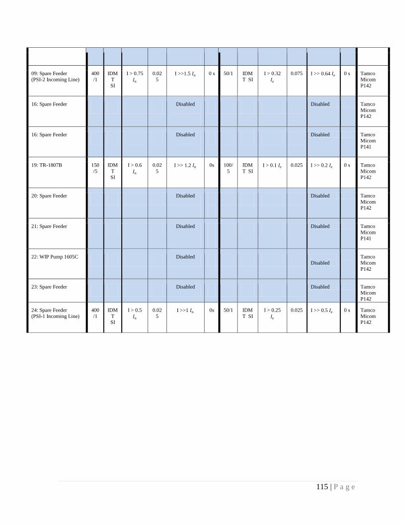
115 | P a g e
09: Spare Feeder
(PSI-2 Incoming Line)
400
/1
IDM
T
SI
I > 0.75
𝐼𝑛
0.02
5 I >>1.5 𝐼𝑛
0 s
50/1 IDM
T SI
I > 0.32
𝐼𝑒
0.075 I >> 0.64 𝐼𝑒 0 s Tamco
Micom
P142
16: Spare Feeder Disabled
Disabled Tamco
Micom P142
16: Spare Feeder Disabled
Disabled Tamco
Micom
P141
19: TR-1807B 150
/5
IDM
T
SI
I > 0.6
𝐼𝑛
0.02
5 I >> 1.2 𝐼𝑛
0s
100/
5
IDM
T SI I > 0.1 𝐼𝑒 0.025 I >> 0.2 𝐼𝑒 0 s Tamco
Micom
P142
20: Spare Feeder Disabled
Disabled Tamco
Micom P142
21: Spare Feeder Disabled
Disabled Tamco
Micom P141
22: WIP Pump 1605C Disabled
Disabled
Tamco
Micom
P142
23: Spare Feeder Disabled Disabled Tamco Micom
P142
24: Spare Feeder
(PSI-1 Incoming Line)
400
/1
IDM
T SI
I > 0.5
𝐼𝑛
0.02
5 I >>1 𝐼𝑛
0s
50/1 IDM
T SI
I > 0.25
𝐼𝑒
0.025 I >> 0.5 𝐼𝑒 0 s Tamco
Micom P142

116 | P a g e
Incomer Overcurrent protection [67] Earth protection [67N] Relay Type
C.T.
ratio
Delay
curve
type
Current
setting
Time
setting
Instantaneous
protection
(DMT)
Time C.T.
ratio
Delay
curve
type
Current
setting
Time
setting
Instantaneous
protection
(DMT)
Time
03: Transformer
(TR-1806A)
800/1 IDMT SI
I > 0.7𝐼𝑛 0.35 Disabled 50/1 IDMT SI
I
>3.2𝐼𝑒
0.025 I > >10𝐼𝑒 0 s Tamco Micom
P142
18:
Transformer (TR-1806A)
800/1 IDMT
SI
I > 0.7
𝐼𝑛
0.375 Disabled 50/1 IDMT
SI
I > 3.2
𝐼𝑒
0.025 I > >10𝐼𝑒 0 s Tamco
Micom P142
DH08: Bus
section
1500/1 IDMT
SI
I >
0.41𝐼𝑛
0.325 Disabled 50/1 IDMT
SI
I > 3.4
𝐼𝑒
0.075 Disabled Tamco
Micom
P143
Table C.29 11kV Bus-section & 11kV Transformer feeders
Table C.30 33kV Transformer Feeders
Transformer
feeders
Overcurrent protection [50/51] Earth protection [50N/51N] Relay
Type
C.T. ratio
Delay curve
type
Current setting
Time setting
Instantaneous protection
(DMT)
Time C.T. ratio
Delay curve
type
Current setting
Time setting
Instantaneous protection
(DMT)
Time
H8: Transformer
(TR-1806A)
250/1 IDMT
SI
I > 1.4
𝐼𝑛
0.25 Disabled 75/1 IDMT
SI
I > 0.3
𝐼𝑒
0.25 Disabled AREVA
P121
250/1 IDMT
SI
I > 1.4
𝐼𝑛
0.25 Disabled 250/1 IDMT
SI
I > 0.1
𝐼𝑒
0.25 Disabled AREVA
P142
H11:Transformer
( TR-1806B )
250/1 IDMT
SI
I > 1.4
𝐼𝑛
0.25 Disabled 75/1 IDMT
SI
I > 0.3
𝐼𝑒
0.25 Disabled AREVA
P121
250/1 IDMT
SI
I > 1.4
𝐼𝑛
0.25 Disabled 250/1 IDMT
SI
I > 0.1
𝐼𝑒
0.25 Disabled AREVA
P142

117 | P a g e
Table C.31 33kV outgoings
Incomer Overcurrent protection [50/51] Earth protection [50N/51N] Relay Type
C.T.
ratio
Delay
curve
type
Current
setting
Time
setting
Instantaneous
protection
(DMT)
Time C.T.
ratio
Delay
curve
type
Current
setting
Time
setting
Instantaneous
protection
(DMT)
Time
H1: FNE 1
150/1 IDMT SI
I >1.2𝐼𝑛 0.15 I >>11.5𝐼𝑛 0 s 50/1 IDMT SI
I >
0.6𝐼𝑒
0.15 I >> 34𝐼𝑒 0 s Areva P123
H3: KEYI 1
100/1 IDMT SI
I >
1.3𝐼𝑛
0.15 I >> 14 𝐼𝑛 0 s 50/1 IDMT SI
I > 0.45
𝐼𝑒
0.15 I >> 24 𝐼𝑒 0s Areva P123
H5:
MOGA 1
150/1 IDMT
SI
I > 0.9
𝐼𝑛
0.3 I >> 11.2 𝐼𝑛 0 s 50/1 IDMT
SI I > 1 𝐼𝑒 0.3 I >> 28 𝐼𝑒 0 s Areva
P123
H15:
KEYI 2
100/1 IDMT
SI
I > 1.3
𝐼𝑛
0.15 I >>14 𝐼𝑛 0s 50/1 IDMT
SI
I > 0.45
𝐼𝑒
0.15 I >> 24 𝐼𝑒 0 s Areva
P123
H13: MOGA
2
150/1 IDMT SI
I > 0.9
𝐼𝑛
0.3 I >> 11.2𝐼𝑛 0s 50/1 IDMT SI
I > 1𝐼𝑒 0.3 I >> 28 𝐼𝑒 0 s Areva P123
H17:
FNE 2
150/1 IDMT
SI
I > 1.2
𝐼𝑛
0.15 I >> 11.5 𝐼𝑛 0 s 50/1 IDMT
SI
I > 0.6
𝐼𝑒
0.15 I >> 34 𝐼𝑒 0 s Areva
P123