OVERCOMING DENSE DEPLOYMENT · PDF fileLargest MW network in Lagos, Nigeria. ... Basic...
24
OVERCOMING DENSE DEPLOYMENT CHALLENGES Martins Dzelde Senior Sales Engineer
-
Upload
duongtuong -
Category
Documents
-
view
220 -
download
0
Transcript of OVERCOMING DENSE DEPLOYMENT · PDF fileLargest MW network in Lagos, Nigeria. ... Basic...

OVERCOMING DENSE DEPLOYMENT CHALLENGES
Martins Dzelde
Senior Sales Engineer


Agenda
SAF Link planning team – success story
Interference countermeasures
Link planning and interference analysis
Antennas
Using Spectrum Compact for Interference Detection
3

SAF global footprint map
4

Link planning success story
Largest MW network in Lagos, Nigeria.
More than 200 SAF links deployed in area of approx. 15 x 20 miles
Detailed path analysis for interference for max frequency re-use
Calculated for best antenna size, Tx power for minimal number of channels
5

Interference Countermeasures
Measures to decrease the influence of interfering signals:
• other RF channel (or band)
• change of antennas
• higher discrimination(high, ultra-high performance antennas etc.)
• larger antenna size
• change of polarization
• Attenuation by obstruction
• new routing
Tx power adjustment of interfering radio
6
Link planning & Radio signal propagation

Basic planning data
• Network configuration
• Location of terminal stations
• Capacity/interface demand, initial and predicted
• Radio-frequency bands available
• Existing radio sites in the area
• Performance and availability requirements

Frequency allocation guide Actual distance varies
depending on rain-zone, tower heights, availability requirements.
8 GHz10.5 GHz
18 GHz
23 GHz
7 miles
14 miles
30 miles 45 miles
Frequency bands Path Length Typical application
23 GHz and above < 7 miles Access network
18 GHz 14 miles Short haul, within cities
10.5 GHz 30 milesLong haul,
over the sea8 GHz 45 miles
< 5 GHz 37-50 mile, > 60 miles

Tx band allocation
Determination of Tx band allocation at each site:
• Low band (LB) Tx < Rx• High band (HB) Tx > RX
HB
LB
LB
LB
LB
LB
LB
HB HB
HB
HB
HB
HB
HB
LB

Fresnel zone• Radio signal does not propagate as a singe beam.
• Nearly half of the Rx signal energy travels through the Fresnel ellipsoid.
• Any obstruction within the Fresnel zone can cause obstruction loss.
• Fresnel radius depends on frequecy band and link distance
• Higher frequency bands have smaller Fresnel ellipsoids
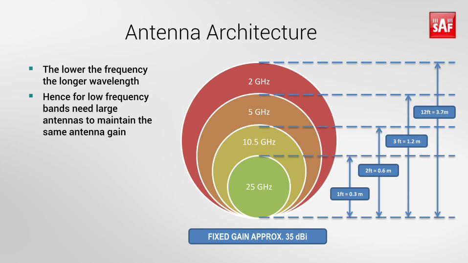
Antenna Architecture
The lower the frequency the longer wavelength
Hence for low frequency bands need large antennas to maintain the same antenna gain
2 GHz
5 GHz
10.5 GHz
25 GHz1ft = 0.3 m
2ft = 0.6 m
3 ft = 1.2 m
12ft = 3.7m
FIXED GAIN APPROX. 35 dBi

Antenna Theory
Small size antennas
Antennas sized up to 4ft have wider main beam and more evident side lobes
Typical error – antenna is aligned on side lobes
Large size antennas
Bigger antennas with higher gain have a narrow main beam and less relevant sidelobes.
Typical problem for installation crew –finding the first signal from the far side site.
13

Antenna alignment
Ensure both antennas are aligned to the main lobe
Avoid alignment on a side lobe or a strong reflected signal

Antennas: Class 3 vs Class 4
Improved side-lobe suppression and F/B ratio
Better frequency reuse:
• Improved interference discrimination• up to 67% more links: 10 links of C4 vs 6 links of C3 on the same site
15

Antenna upgrade
Replacing existing antennas with higher performance antennas which side lobes are more isolated thus received reflected signal through side lobes will be weaker

Shielding example
Use natural obstacle for shielding antenna from multipath or other interfering signal
Spectrum Compact for site analysis

Interference Countermeasures
Measures to decrease the influence of interfering signals:
• other RF channel (or band)
• change of antennas
• higher discrimination(high, ultra-high performance antennas etc.)
• larger antenna size
• change of polarization
• Attenuation by obstruction
• new routing
Tx power adjustment of interfering radio
18

19
• Smallest fully functional spectrum analyzer
• Functionality of three devices: spectrum analyzer, power meter, antenna alignment tool
• Control the work quality of subcontractors
• Saving spectrum scans for future reference
• Quick interference detection
• Easy RF troubleshooting
• No hidden costs – all updates, PC SW included in the price
Spectrum Compact

Case study – mobile operator
LMT Network
Location: Latvia, entire area
Link distance: 600 m up to 35 km
Frequency bands in use: 6, 13, 18, 23, 26, 32, 38 GHz
Antenna diameter: 0.3 m-1.8 m
20

In the field – using handheld directional antennas for higher gain demands
21
Horn type J0AA0610HG02 J0AA1115HG01 J0AA1724HG01 J0AA2640HG03
Covered frequency range, GHz
5.925-11.000 10.700-17.000 17.000-26.500 26.500-40.000
Typical Gain, dBi 14.5-18 19.5-20.5 21.0-21.5 20.5-21.5

Spectrum Compact for finding Free Channel
Free radio channel selection
Useful in license-free bands e.g.
17GHz and 24Ghz radios
Useful functionality in countries with
weak or no spectrum Regulatory supervision
With the Spectrum Compact, it is possible to determine whether there is the necessary guard band for transmission.
22

Spectrum Compact for Interference detection
23
Way better sensitivity and bandwidth resolution than built-in spectrum analyzers in a radio
Market leading sensitivity -105 dBm/MHz

SAF Tehnika © 2017, www.saftehnika.com
Thank you!
24