
Ovation Point Builder - Powergenics
145
10/02 i U3-1041 (Rev 2) Ovation Point Builder Section Title Page Emerson Process Management Proprietary Class 2C Section 1. Introduction 1-1. Document Overview . . . . . . . . . . . . . . . . . . . . . . . . . . . . . . . . . . . . . . . . . . . . . . . . . 1-1 1-2. Contents of this Document . . . . . . . . . . . . . . . . . . . . . . . . . . . . . . . . . . . . . . . . . . . . 1-1 1-3. Point Builder User Interface . . . . . . . . . . . . . . . . . . . . . . . . . . . . . . . . . . . . . . . . . . . 1-2 1-4. Configuring the Point Builder. . . . . . . . . . . . . . . . . . . . . . . . . . . . . . . . . . . . . . . . . . 1-3 1-5. Point Builder Features. . . . . . . . . . . . . . . . . . . . . . . . . . . . . . . . . . . . . . . . . . . . . . . . 1-4 1-5.1. Consistency Checking . . . . . . . . . . . . . . . . . . . . . . . . . . . . . . . . . . . . . . . . . 1-4 1-5.2. I/O Point Hardware Mapping. . . . . . . . . . . . . . . . . . . . . . . . . . . . . . . . . . . . 1-4 1-5.3. Point Referencing. . . . . . . . . . . . . . . . . . . . . . . . . . . . . . . . . . . . . . . . . . . . . 1-5 1-5.4. Point Filtering . . . . . . . . . . . . . . . . . . . . . . . . . . . . . . . . . . . . . . . . . . . . . . . 1-5 1-5.5. HSR PIC File Generation. . . . . . . . . . . . . . . . . . . . . . . . . . . . . . . . . . . . . . . 1-5 1-6. Point Names . . . . . . . . . . . . . . . . . . . . . . . . . . . . . . . . . . . . . . . . . . . . . . . . . . . . . . . 1-6 1-7. Reference Documents . . . . . . . . . . . . . . . . . . . . . . . . . . . . . . . . . . . . . . . . . . . . . . . . 1-8 Section 2. Quick Procedure Guide 2-1. Section Overview . . . . . . . . . . . . . . . . . . . . . . . . . . . . . . . . . . . . . . . . . . . . . . . . . . . 2-1 2-2. Accessing the Point Builder . . . . . . . . . . . . . . . . . . . . . . . . . . . . . . . . . . . . . . . . . . . 2-1 2-3. Search Window . . . . . . . . . . . . . . . . . . . . . . . . . . . . . . . . . . . . . . . . . . . . . . . . . . . . . 2-1 2-4. Creating a Point. . . . . . . . . . . . . . . . . . . . . . . . . . . . . . . . . . . . . . . . . . . . . . . . . . . . . 2-2 2-5. Modifying a Point . . . . . . . . . . . . . . . . . . . . . . . . . . . . . . . . . . . . . . . . . . . . . . . . . . . 2-2 2-6. Deleting a Point. . . . . . . . . . . . . . . . . . . . . . . . . . . . . . . . . . . . . . . . . . . . . . . . . . . . . 2-2 2-7. Printing . . . . . . . . . . . . . . . . . . . . . . . . . . . . . . . . . . . . . . . . . . . . . . . . . . . . . . . . . . . 2-3 2-8. Generating HSR PIC Files . . . . . . . . . . . . . . . . . . . . . . . . . . . . . . . . . . . . . . . . . . . . 2-3 2-9. Consistency Checking. . . . . . . . . . . . . . . . . . . . . . . . . . . . . . . . . . . . . . . . . . . . . . . . 2-3 2-10. Accessing the Point Group Builder. . . . . . . . . . . . . . . . . . . . . . . . . . . . . . . . . . . . . . 2-4 2-11. Modifying or Adding a Point Trend Group . . . . . . . . . . . . . . . . . . . . . . . . . . . . . . . 2-4 2-12. Modifying or Adding an HSR Point Group . . . . . . . . . . . . . . . . . . . . . . . . . . . . . . . 2-5 2-13. Modifying or Adding a PDS Point Group . . . . . . . . . . . . . . . . . . . . . . . . . . . . . . . . 2-5 Section 3. Using the Point Builder 3-1. Accessing the Point Builder . . . . . . . . . . . . . . . . . . . . . . . . . . . . . . . . . . . . . . . . . . . 3-1 3-2. Point Builder Main Window . . . . . . . . . . . . . . . . . . . . . . . . . . . . . . . . . . . . . . . . . . . 3-6 3-2.1. Point Tabs . . . . . . . . . . . . . . . . . . . . . . . . . . . . . . . . . . . . . . . . . . . . . . . . . . 3-7 3-2.2. Menu Bar . . . . . . . . . . . . . . . . . . . . . . . . . . . . . . . . . . . . . . . . . . . . . . . . . . . 3-8 3-2.3. Icon/Control Bar . . . . . . . . . . . . . . . . . . . . . . . . . . . . . . . . . . . . . . . . . . . . 3-10 3-2.4. Point Name Indicator . . . . . . . . . . . . . . . . . . . . . . . . . . . . . . . . . . . . . . . . . 3-11 3-2.5. Bottom Status Bar . . . . . . . . . . . . . . . . . . . . . . . . . . . . . . . . . . . . . . . . . . . 3-11 3-2.6. Search Window . . . . . . . . . . . . . . . . . . . . . . . . . . . . . . . . . . . . . . . . . . . . . 3-12 3-2.7. Where Used Window . . . . . . . . . . . . . . . . . . . . . . . . . . . . . . . . . . . . . . . . . 3-13
Transcript of Ovation Point Builder - Powergenics

Ovation Point Builder
Section Title Page
Section 1. Introduction
1-1. Document Overview . . . . . . . . . . . . . . . . . . . . . . . . . . . . . . . . . . . . . . . . . . . . . . . . . 1-11-2. Contents of this Document . . . . . . . . . . . . . . . . . . . . . . . . . . . . . . . . . . . . . . . . . . . . 1-11-3. Point Builder User Interface . . . . . . . . . . . . . . . . . . . . . . . . . . . . . . . . . . . . . . . . . . . 1-21-4. Configuring the Point Builder. . . . . . . . . . . . . . . . . . . . . . . . . . . . . . . . . . . . . . . . . . 1-31-5. Point Builder Features. . . . . . . . . . . . . . . . . . . . . . . . . . . . . . . . . . . . . . . . . . . . . . . . 1-4
1-5.1. Consistency Checking . . . . . . . . . . . . . . . . . . . . . . . . . . . . . . . . . . . . . . . . . 1-41-5.2. I/O Point Hardware Mapping. . . . . . . . . . . . . . . . . . . . . . . . . . . . . . . . . . . . 1-41-5.3. Point Referencing. . . . . . . . . . . . . . . . . . . . . . . . . . . . . . . . . . . . . . . . . . . . . 1-51-5.4. Point Filtering . . . . . . . . . . . . . . . . . . . . . . . . . . . . . . . . . . . . . . . . . . . . . . . 1-51-5.5. HSR PIC File Generation. . . . . . . . . . . . . . . . . . . . . . . . . . . . . . . . . . . . . . . 1-5
1-6. Point Names . . . . . . . . . . . . . . . . . . . . . . . . . . . . . . . . . . . . . . . . . . . . . . . . . . . . . . . 1-61-7. Reference Documents . . . . . . . . . . . . . . . . . . . . . . . . . . . . . . . . . . . . . . . . . . . . . . . . 1-8
Section 2. Quick Procedure Guide
2-1. Section Overview . . . . . . . . . . . . . . . . . . . . . . . . . . . . . . . . . . . . . . . . . . . . . . . . . . . 2-12-2. Accessing the Point Builder . . . . . . . . . . . . . . . . . . . . . . . . . . . . . . . . . . . . . . . . . . . 2-12-3. Search Window. . . . . . . . . . . . . . . . . . . . . . . . . . . . . . . . . . . . . . . . . . . . . . . . . . . . . 2-12-4. Creating a Point. . . . . . . . . . . . . . . . . . . . . . . . . . . . . . . . . . . . . . . . . . . . . . . . . . . . . 2-22-5. Modifying a Point . . . . . . . . . . . . . . . . . . . . . . . . . . . . . . . . . . . . . . . . . . . . . . . . . . . 2-22-6. Deleting a Point. . . . . . . . . . . . . . . . . . . . . . . . . . . . . . . . . . . . . . . . . . . . . . . . . . . . . 2-22-7. Printing . . . . . . . . . . . . . . . . . . . . . . . . . . . . . . . . . . . . . . . . . . . . . . . . . . . . . . . . . . . 2-32-8. Generating HSR PIC Files . . . . . . . . . . . . . . . . . . . . . . . . . . . . . . . . . . . . . . . . . . . . 2-32-9. Consistency Checking. . . . . . . . . . . . . . . . . . . . . . . . . . . . . . . . . . . . . . . . . . . . . . . . 2-32-10. Accessing the Point Group Builder. . . . . . . . . . . . . . . . . . . . . . . . . . . . . . . . . . . . . . 2-42-11. Modifying or Adding a Point Trend Group . . . . . . . . . . . . . . . . . . . . . . . . . . . . . . . 2-42-12. Modifying or Adding an HSR Point Group . . . . . . . . . . . . . . . . . . . . . . . . . . . . . . . 2-52-13. Modifying or Adding a PDS Point Group . . . . . . . . . . . . . . . . . . . . . . . . . . . . . . . . 2-5
Section 3. Using the Point Builder
3-1. Accessing the Point Builder . . . . . . . . . . . . . . . . . . . . . . . . . . . . . . . . . . . . . . . . . . . 3-13-2. Point Builder Main Window. . . . . . . . . . . . . . . . . . . . . . . . . . . . . . . . . . . . . . . . . . . 3-6
3-2.1. Point Tabs . . . . . . . . . . . . . . . . . . . . . . . . . . . . . . . . . . . . . . . . . . . . . . . . . . 3-73-2.2. Menu Bar . . . . . . . . . . . . . . . . . . . . . . . . . . . . . . . . . . . . . . . . . . . . . . . . . . . 3-83-2.3. Icon/Control Bar . . . . . . . . . . . . . . . . . . . . . . . . . . . . . . . . . . . . . . . . . . . . 3-103-2.4. Point Name Indicator . . . . . . . . . . . . . . . . . . . . . . . . . . . . . . . . . . . . . . . . . 3-113-2.5. Bottom Status Bar . . . . . . . . . . . . . . . . . . . . . . . . . . . . . . . . . . . . . . . . . . . 3-113-2.6. Search Window . . . . . . . . . . . . . . . . . . . . . . . . . . . . . . . . . . . . . . . . . . . . . 3-123-2.7. Where Used Window. . . . . . . . . . . . . . . . . . . . . . . . . . . . . . . . . . . . . . . . . 3-13
10/02 i U3-1041 (Rev 2)Emerson Process Management Proprietary Class 2C

Table of Contents, Con’t
Section Title Page
3-3. Point Type Descriptions . . . . . . . . . . . . . . . . . . . . . . . . . . . . . . . . . . . . . . . . . . . . . 3-143-3.1. Applications . . . . . . . . . . . . . . . . . . . . . . . . . . . . . . . . . . . . . . . . . . . . . . . . 3-14
3-4. Point Record Types. . . . . . . . . . . . . . . . . . . . . . . . . . . . . . . . . . . . . . . . . . . . . . . . . 3-153-4.1. Long Analog Points (LA) . . . . . . . . . . . . . . . . . . . . . . . . . . . . . . . . . . . . . 3-153-4.2. Long Digital Points (LD) . . . . . . . . . . . . . . . . . . . . . . . . . . . . . . . . . . . . . . 3-153-4.3. Long Packed Points (LP) . . . . . . . . . . . . . . . . . . . . . . . . . . . . . . . . . . . . . . 3-163-4.4. Packed Digital Points (PD) . . . . . . . . . . . . . . . . . . . . . . . . . . . . . . . . . . . . 3-163-4.5. Algorithm Points (LC) . . . . . . . . . . . . . . . . . . . . . . . . . . . . . . . . . . . . . . . . 3-163-4.6. Drop Points (DU). . . . . . . . . . . . . . . . . . . . . . . . . . . . . . . . . . . . . . . . . . . . 3-163-4.7. Module Points (RM) . . . . . . . . . . . . . . . . . . . . . . . . . . . . . . . . . . . . . . . . . 3-173-4.8. Node Points (RN). . . . . . . . . . . . . . . . . . . . . . . . . . . . . . . . . . . . . . . . . . . . 3-17
3-5. Record Type Folder Tabs . . . . . . . . . . . . . . . . . . . . . . . . . . . . . . . . . . . . . . . . . . . . 3-183-5.1. LA Record Type Point Folder . . . . . . . . . . . . . . . . . . . . . . . . . . . . . . . . . . 3-193-5.2. DA Record Type Point Folder . . . . . . . . . . . . . . . . . . . . . . . . . . . . . . . . . . 3-203-5.3. LD Record Type Point Folder . . . . . . . . . . . . . . . . . . . . . . . . . . . . . . . . . . 3-213-5.4. DD Record Type Point Folder . . . . . . . . . . . . . . . . . . . . . . . . . . . . . . . . . . 3-223-5.5. LP Record Type Point Folder . . . . . . . . . . . . . . . . . . . . . . . . . . . . . . . . . . 3-233-5.6. DP Record Type Point Folder . . . . . . . . . . . . . . . . . . . . . . . . . . . . . . . . . . 3-243-5.7. PD Record Type Point Folder . . . . . . . . . . . . . . . . . . . . . . . . . . . . . . . . . . 3-253-5.8. LC Record Type Point Folder . . . . . . . . . . . . . . . . . . . . . . . . . . . . . . . . . . 3-263-5.9. DU Record Type Point Folder . . . . . . . . . . . . . . . . . . . . . . . . . . . . . . . . . . 3-273-5.10. RM Record Type Point Folder. . . . . . . . . . . . . . . . . . . . . . . . . . . . . . . . . . 3-283-5.11. RN Record Type Point Folder . . . . . . . . . . . . . . . . . . . . . . . . . . . . . . . . . . 3-29
3-6. Creating a Point. . . . . . . . . . . . . . . . . . . . . . . . . . . . . . . . . . . . . . . . . . . . . . . . . . . . 3-303-7. Modifying a Point . . . . . . . . . . . . . . . . . . . . . . . . . . . . . . . . . . . . . . . . . . . . . . . . . . 3-313-8. Deleting a Point. . . . . . . . . . . . . . . . . . . . . . . . . . . . . . . . . . . . . . . . . . . . . . . . . . . . 3-323-9. Printing . . . . . . . . . . . . . . . . . . . . . . . . . . . . . . . . . . . . . . . . . . . . . . . . . . . . . . . . . . 3-323-10. Generating HSR PIC Files . . . . . . . . . . . . . . . . . . . . . . . . . . . . . . . . . . . . . . . . . . . 3-323-11. Checking Consistency. . . . . . . . . . . . . . . . . . . . . . . . . . . . . . . . . . . . . . . . . . . . . . . 3-34
Section 4. Using the Point Group Builder
4-1. Section Overview . . . . . . . . . . . . . . . . . . . . . . . . . . . . . . . . . . . . . . . . . . . . . . . . . . . 4-14-2. Accessing the Point Group Builder. . . . . . . . . . . . . . . . . . . . . . . . . . . . . . . . . . . . . . 4-14-3. Modifying or Adding a Point Trend Group . . . . . . . . . . . . . . . . . . . . . . . . . . . . . . . 4-34-4. Modifying or Adding an HSR Point Group . . . . . . . . . . . . . . . . . . . . . . . . . . . . . . 4-194-5. Modifying or Adding a PDS Point Group . . . . . . . . . . . . . . . . . . . . . . . . . . . . . . . 4-22
Appendix A. Descriptions of Tab Fields
A-1. Section Overview . . . . . . . . . . . . . . . . . . . . . . . . . . . . . . . . . . . . . . . . . . . . . . . . . . A-1A-2. Point Tab Descriptions . . . . . . . . . . . . . . . . . . . . . . . . . . . . . . . . . . . . . . . . . . . . . . A-2
U3-1041 (Rev 2) ii 10/02Emerson Process Management Proprietary Class 2C
Ovation Point Builder
Section Title Page
A-3. Config Tab Descriptions . . . . . . . . . . . . . . . . . . . . . . . . . . . . . . . . . . . . . . . . . . . . . A-4A-4. Security Tab Descriptions. . . . . . . . . . . . . . . . . . . . . . . . . . . . . . . . . . . . . . . . . . . . A-6A-5. Ancillary Tab Descriptions . . . . . . . . . . . . . . . . . . . . . . . . . . . . . . . . . . . . . . . . . . . A-7A-6. HSR Tab Descriptions . . . . . . . . . . . . . . . . . . . . . . . . . . . . . . . . . . . . . . . . . . . . . . A-8A-7. Initial Tab Descriptions. . . . . . . . . . . . . . . . . . . . . . . . . . . . . . . . . . . . . . . . . . . . . A-12A-8. Alarm Tab Descriptions . . . . . . . . . . . . . . . . . . . . . . . . . . . . . . . . . . . . . . . . . . . . A-13A-9. Hardware Tab Description . . . . . . . . . . . . . . . . . . . . . . . . . . . . . . . . . . . . . . . . . . A-15A-10. Display Tab Descriptions . . . . . . . . . . . . . . . . . . . . . . . . . . . . . . . . . . . . . . . . . . . A-19A-11. Byte Params Tab Descriptions . . . . . . . . . . . . . . . . . . . . . . . . . . . . . . . . . . . . . . . A-20A-12. Instrumentation Tab Description . . . . . . . . . . . . . . . . . . . . . . . . . . . . . . . . . . . . . A-21A-13. Int Params Tab Descriptions. . . . . . . . . . . . . . . . . . . . . . . . . . . . . . . . . . . . . . . . . A-25A-14. Real Param Tab Descriptions . . . . . . . . . . . . . . . . . . . . . . . . . . . . . . . . . . . . . . . . A-26A-15. Plant Mode Tab Description . . . . . . . . . . . . . . . . . . . . . . . . . . . . . . . . . . . . . . . . . A-27A-16. Limits Tab Descriptions . . . . . . . . . . . . . . . . . . . . . . . . . . . . . . . . . . . . . . . . . . . . A-28
Appendix B. Examples of Creating Points
B-1. Section Overview . . . . . . . . . . . . . . . . . . . . . . . . . . . . . . . . . . . . . . . . . . . . . . . . . . . B-1B-1.1. Using the Search Window . . . . . . . . . . . . . . . . . . . . . . . . . . . . . . . . . . . . . . B-1
B-2. Creating Analog Input Points . . . . . . . . . . . . . . . . . . . . . . . . . . . . . . . . . . . . . . . . . . B-2B-3. Creating Analog Output Points. . . . . . . . . . . . . . . . . . . . . . . . . . . . . . . . . . . . . . . . . B-3B-4. Creating Digital Input Points . . . . . . . . . . . . . . . . . . . . . . . . . . . . . . . . . . . . . . . . . . B-4B-5. Creating Digital Output Point . . . . . . . . . . . . . . . . . . . . . . . . . . . . . . . . . . . . . . . . . . B-5B-6. Creating Packed Digital Points . . . . . . . . . . . . . . . . . . . . . . . . . . . . . . . . . . . . . . . . . B-6B-7. Creating Packed Digital I/O Points. . . . . . . . . . . . . . . . . . . . . . . . . . . . . . . . . . . . . . B-7B-8. Creating Algorithm Points . . . . . . . . . . . . . . . . . . . . . . . . . . . . . . . . . . . . . . . . . . . . B-8B-9. Creating Drop Points. . . . . . . . . . . . . . . . . . . . . . . . . . . . . . . . . . . . . . . . . . . . . . . . . B-9B-10. Creating Module Points . . . . . . . . . . . . . . . . . . . . . . . . . . . . . . . . . . . . . . . . . . . . . B-10B-11. Creating Node Points . . . . . . . . . . . . . . . . . . . . . . . . . . . . . . . . . . . . . . . . . . . . . . . B-11B-12. Creating Analog/Thermocouple Points. . . . . . . . . . . . . . . . . . . . . . . . . . . . . . . . . . B-12B-13. Creating Analog/RTD Points . . . . . . . . . . . . . . . . . . . . . . . . . . . . . . . . . . . . . . . . . B-13B-14. Creating Pulse Accumulator Points . . . . . . . . . . . . . . . . . . . . . . . . . . . . . . . . . . . . B-16B-15. Creating HART Analog Input Points . . . . . . . . . . . . . . . . . . . . . . . . . . . . . . . . . . . B-17B-16. Creating HART Analog Output Points . . . . . . . . . . . . . . . . . . . . . . . . . . . . . . . . . . B-18B-17. Guidelines for Creating Third Party Points . . . . . . . . . . . . . . . . . . . . . . . . . . . . . . B-19
B-17.1. Creating Points for an Allen-Bradley Driver . . . . . . . . . . . . . . . . . . . . . . . B-21B-17.2. Creating Points for a Modbus Driver. . . . . . . . . . . . . . . . . . . . . . . . . . . . . B-24B-17.3. Creating Points for an RTP IOBC Driver (Real Time Products). . . . . . . . B-25B-17.4. Creating Points for a General Electric Mark V Driver . . . . . . . . . . . . . . . B-26B-17.5. Creating Points for a General Electric Mark VI Driver. . . . . . . . . . . . . . . B-28
10/02 iii U3-1041 (Rev 2)Emerson Process Management Proprietary Class 2C


10/02 Changes-1 U3-1041 (Rev 2)Emerson Process Management Proprietary Class 2C
Summary of Changes
This revision of “Ovation Point Builder User Guide” (U3-1041) includes thefollowing changes:
• Added a Quick Procedures Section, titled Section 2.
• Added PD Record type to Section 3.
• Updated Hardware tab with defined fields when creating a point.
• Added five additional keyword options to RTP third party driver.
• Appendix A added screen captures for each point tab description.
• Appendix B provides examples for creating points.

Section 1. Introduction
1-1. Document Overview
The Ovation Point Builder provides a graphical user interface for creating anddeleting points, and modifying existing point attributes.
The Point Builder includes folders and tabs which contain point attributes and aredefined in Appendix A. For more information on point attribute record types see“Ovation Record Types Reference” (R3-1140) for each defined record type. Inaddition, the points also include attributes related to hardware information,grouping information, and Ovation Historian Point Information Compiler (PIC)attributes.
1-2. Contents of this Document
This document is organized into the following sections:
• Section 1. Introduction provides an overview of the Point Builder, defines thecontents of this document and lists other documents that might be helpful to theuser.
• Section 2. Quick Procedure Guide provides condensed procedures that aredescribed in detail in the rest of the manual.
• Section 3. Using the Point Builder describes how to access and use the PointBuilder.
• Section 4. Using the Point Group Builder describes how to access and use thePoint Group Builder.
• Appendix A.Description of Tab Fields describes the Tab Fields.
• Appendix B.Examples of Creating Points provides guidelines for creatingpoints.
10/02 1-1 U3-1041 (Rev 2)Emerson Process Management Proprietary Class 2C

1-3. Point Builder User Interface
1-3. Point Builder User Interface
The Point Builder user interface is the standard interface to the point database. ThePoint Builder presents the points as a series of folder tabs as shown inFigure 1-1. Each tab contains a set of attributes related to the tab heading.
The user can choose to start editing a new point right away, or view an existing pointvia the search button or menu item. The point can then be added or deleted with theadd/delete buttons or menu items.
Figure 1-1. Point Builder Window
U3-1041 (Rev 2) 1-2 10/02Emerson Process Management Proprietary Class 2C

1-4. Configuring the Point Builder
1-4. Configuring the Point Builder
The Point Builder software configuration is performed through the Init Tool and theAdmin Tool. The following software packages are needed for the specified drops toconfigure the Point Builder function via the Init Tool.
Note
Detailed instructions for accessing and usingthe Init and Admin Tools can be found in“Using the Ovation Init and Admin Tool”(R3-1105).
In order to use the Point Builder systemwide, the following software packages mustbe available on the indicated drops.
Table 1-1. Configuration Point Builder Packages
Drop Available package
SS/EWS:(Software Server/Engineer Work Station)
Power Tools Master Database Install/CreatePower Tools Distributed Database Install/CreatePower Tools Base Software SupportPower Tools Database Server FunctionsPower Tools Base User Interface
SS and StandAlone HS/LS:(Software Server/Historian/Log Server)
Power Tools Master Database Install/CreatePower Tools Distributed Database Install/CreatePower Tools Base Software SupportPower Tools Database Server Functions
Each EWS:(Engineering Work Station)
Power Tools Distributed Database Install/CreatePower Tools Base Software SupportPower Tools Base User Interface
All WEStation drop types-(OS Operator Station)(HSR/LS Log Server/Historian)(CS Control Server)(DL Data Link)
Power Tools Distributed Database Install/CreatePower Tools Base Software Support
Controller, Non-WEStation types None
10/02 1-3 U3-1041 (Rev 2)Emerson Process Management Proprietary Class 2C

1-5. Point Builder Features
1-5. Point Builder Features
The Point Builder provides the following features that are used to manage thesystem points:
• Consistency Checking
• (I/O) Input /Output Point Hardware Mapping
• Point Referencing
• Point Filtering
• HSR PIC File Generation
1-5.1. Consistency Checking
The Point Builder provides immediate feedback to the user regarding consistencychecks. This ensures the following:
• Duplicate point names are not assigned.
• Attribute values for point fields are of the correct type and range.
• All required fields are entered.
• Fields are checked at input times to ensure a valid data type and range.
• Points are checked to ensure various fields make sense in combination with eachother when the point is added or updated.
• Points are checked on a system basis (done via a menu option).
• Whenever a point is deleted, the Point Builder will verify that the point is not inuse by any other critical function. (Specifically, the point cannot be used incontrol or referenced by another Ovation point).
1-5.2. I/O Point Hardware Mapping
The Point Builder allows a user to identify the I/O parameters of each point:
• I/O Type (Ovation, Q-line)
• I/O Location and Card Type
• I/O Channel
U3-1041 (Rev 2) 1-4 10/02Emerson Process Management Proprietary Class 2C
1-5. Point Builder Features
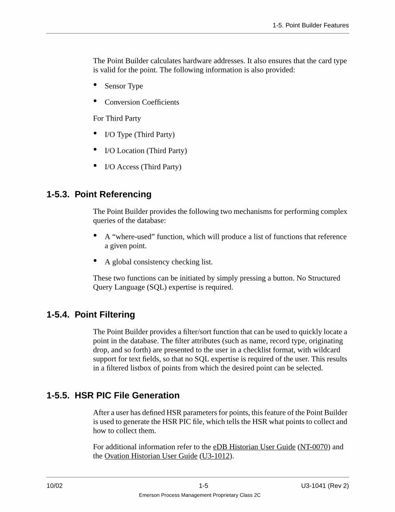
The Point Builder calculates hardware addresses. It also ensures that the card typeis valid for the point. The following information is also provided:
• Sensor Type
• Conversion Coefficients
For Third Party
• I/O Type (Third Party)
• I/O Location (Third Party)
• I/O Access (Third Party)
1-5.3. Point Referencing
The Point Builder provides the following two mechanisms for performing complexqueries of the database:
• A “where-used” function, which will produce a list of functions that referencea given point.
• A global consistency checking list.
These two functions can be initiated by simply pressing a button. No StructuredQuery Language (SQL) expertise is required.
1-5.4. Point Filtering
The Point Builder provides a filter/sort function that can be used to quickly locate apoint in the database. The filter attributes (such as name, record type, originatingdrop, and so forth) are presented to the user in a checklist format, with wildcardsupport for text fields, so that no SQL expertise is required of the user. This resultsin a filtered listbox of points from which the desired point can be selected.
1-5.5. HSR PIC File Generation
After a user has defined HSR parameters for points, this feature of the Point Builderis used to generate the HSR PIC file, which tells the HSR what points to collect andhow to collect them.
For additional information refer to the eDB Historian User Guide (NT-0070) andthe Ovation Historian User Guide (U3-1012).
10/02 1-5 U3-1041 (Rev 2)Emerson Process Management Proprietary Class 2C

1-6. Point Names
1-6. Point Names
The following rules must be followed to ensure valid point names:
1. A fully qualified point name in the Ovation system is of the following format:
“name.unit@network”
This fully qualified name consists of three parameters:
• A 16-character maximum point name.
• A six-character maximum unit name.
• An eight-character maximum network name.
In addition to the above parameters, the “.” and “@” are required and arereserved characters. Therefore, the maximum number of characters in a fullyqualified point name is 32.
2. Characters may be any combination of alphabetic, numeric (0 - 9), or specialpunctuation characters.
3. Point names are not case sensitive. Lower case characters will be converted toupper case.
For example, point name A0113 is considered the same as a0113.
4. Do not include a space in a point name.
5. A point name cannot be a reserved word, or contain reserved characters.
• For a listing of reserved graphic words, refer to “Ovation GraphicsReference Manual” (R3-1120).
• For a listing of reserved point name characters, refer to Table 1-3.
U3-1041 (Rev 2) 1-6 10/02Emerson Process Management Proprietary Class 2C

1-6. Point Names
Table 1-2. Valid Point Name Characters
CharacterASCII
(in HEX) CharacterASCII
(in HEX) CharacterASCII
(in HEX)
! 21 ? 3F V 56
# 23 A 41 W 57
( 28 B 42 X 58
) 29 C 43 Y 59
+ 2B D 44 Z 5A
- 2D E 45 [ 5B
/ 2F F 46 ] 5D
0 30 G 47 ^ 5E
1 31 H 48 _ 5F
2 32 I 49 { 7B
3 33 J 4A | 7C
4 34 K 4B } 7D
5 35 L 4C
6 36 M 4D
7 37 N 4E
8 38 O 4F
9 39 P P
: 3A Q 51
; 3B R 52
< 3C S 53
= 3D T 54
> 3E U 55
10/02 1-7 U3-1041 (Rev 2)Emerson Process Management Proprietary Class 2C

1-7. Reference Documents
Table 1-3. Reserved Point Name Characters
1-7. Reference Documents
Additional reference documents that will be helpful to the Point Builder user arelisted below in Table 1-4.
CharacterASCII
(in HEX) CharacterASCII
(in HEX) CharacterASCII
(in HEX)
$ 24 * 2A ~ 7E
% 25 , 2C ‘ 60
& 26 @ 40 ’ 27
. 2E \ 5C “ 22
Table 1-4. Reference Documents
DocumentNumber Title Description
NoT-0070 eDB Historian User Guide Provides information on the collection and storage ofhistorical data.
R3-1105 Using the Ovation Init andAdmin Tools
Provides information on defining and configuringstations.
R3-1120 Ovation Graphics Reference Provides information on using the graphics utilities tocreate or modify diagrams.
R3-1140 Ovation Record TypesReference.
Describes the point, system, and algorithm recordtypes, along with the purpose and use of records.
U3-1012 Ovation Historian User Guide. Describes the HSR subsystems and their functions.
U3-1032 Ovation Control User Guide Provides information on the Ovation Controller andits functions.
U3-1044 I/O Builder User Guide. Describes the functions and the usage of the OvationI/O Builder.
U3-1045 Security Builder User Guide. Provides a graphical user interface for creating,deleting, and modifying security objects.
U3-1047 Drop Loader User Guide. Provides the user with information for loading pointinformation into the system drops.
U3-1041 (Rev 2) 1-8 10/02Emerson Process Management Proprietary Class 2C

Section 2. Quick Procedure Guide
2-1. Section Overview
This section is a reference guide which provides a condensed version of theprocedures in this manual. This section is intended for users who are experiencedwith the Point Builder applications and procedures. Refer to the manual for detailedinstructions for each of the following sections.
2-2. Accessing the Point Builder(described in detail in Section 3-1)
1. Select the Front Panel menu icon from the control bar at the bottom of theEngineering Station.
2. Select the User Login/Menu item.
3. Enter the Username and Password.
4. Select the Login button.
5. Select the Tools.
6. Select the Power Tools.
7. Select Point Builder from the Power Tools Menu.
2-3. Search Window(described in detail in Section 3-2.6)
1. Select the Search icon from the Point Builder Main window.
2. Enter the point name you want to search for in the database.
3. Select the List button. This activates the search process.
4. If an error was made while entering the point name, select the Clear button andenter the point name again.
5. Select Apply to enter the selected point name to the Point Builder window.
6. To exit the Search window, select the Dismiss button.
10/02 2-1 U3-1041 (Rev 2)Emerson Process Management Proprietary Class 2C

2-1. Section Overview
2-4. Creating a Point(described in detail in Section 3-6)
1. Access the point tab in the Point Builder window and select the desired recordtype for the point you want to create.
2. Enter a point name.
3. Select each tab/folder and apply or enter the appropriate information in eachfield.
4. Select the Add icon from the Point Builder Main Window.
5. Use the Drop Loader tool to load the points to the Controller. Refer toAppendix A for tab field descriptions and Appendix B. for additional examplesof creating points.
2-5. Modifying a Point(described in detail in Section 3-7)
1. From the Point folder, select the Point tab.
2. Enter the Name of the point that you want to modify.
3. Select the Drop Number from the Originating Drop pull down menu.
4. From the Point folder, select the Security tab.
5. Select the appropriate Security information.
6. Make any other desired changes.
7. Select the Add icon from the Point Builder Main Window.
2-6. Deleting a Point(described in detail in Section 3-8)
1. Select the Point tab from the Point Folder.
2. Enter the Point Name you want to delete.
3. Select the Delete icon from the Point Builder Main Window or select Deletefrom the Point pull-down menu.
U3-1041 (Rev 2) 2-2 10/02Emerson Process Management Proprietary Class 2C

2-1. Section Overview
2-7. Printing(described in detail in Section 3-9)
1. Select the Point tab from the Point Folder.
2. Enter the Point Name you want to print information about.
3. Select the Print icon from the Point Builder Main Window.
2-8. Generating HSR PIC Files(described in detail in Section 3-10)
1. Select the Generate HSR PIC files icon from the Point Builder Main Window,the HSR PIC File pop-up window appears.
2. Select the desired drop from the Drop pull down menu.
3. Select the desired Unit from the Net/Unit Filter scrolling list.
4. Select Generate to list all the files in the system.
5. Select Dismiss to dismiss the window.
2-9. Consistency Checking(described in detail in Section 3-11)
1. Select the Consistency Checking icon from the Point Builder Main Window.
2. Select Check and all the point inconsistencies from the database are listed.
3. Select Print to print all the inconsistencies listed.
4. Select Print Options to change the printer settings.
5. Select Dismiss to dismiss the window.
10/02 2-3 U3-1041 (Rev 2)Emerson Process Management Proprietary Class 2C

2-1. Section Overview
2-10. Accessing the Point Group Builder(described in detail in Section 4-2)
1. Select Point Group Builder from the Power Tools Menu.
2. The Point Group Builder window appears.
2-11. Modifying or Adding a Point Trend Group(described in detail in Section 4-3)
1. Select Trend Groups (default option) from the View pull-down menu on thePoint Group Builder window.
2. Select a group from the Group List.
3. Select Modify. All fields can be modified except the Group Number.
OR
Select Add Group from the Point Group Builder window.
4. Enter a global group number (to define the group) in the Group Number field.The Group Number is used to identify group information.
5. Enter the trend group name in the name field, using up to 30 characters.
6. Enter the title of the trend group in the title field, using up to 30 characters.
7. Pull down the Live Interval menu and select an interval.
8. Pull down the Layout menu. Select a trend layout type.
9. To enter live (or historical) information about the trend currently displayed inthe window, select the Fill Info from Trend button.
10. To modify an existing point, select a point from the scrolling list and then selectModify from the Group Attributes window.
11. To delete one of the point entries, select the box which has the point to bedeleted. The point will appear in the name entry field.Select the Delete key.
12. To add a point, select Add Point from the Group Attributes window.
13. Enter the desired point name in the name entry field.
14. When all information for the point has been entered, select the OK or Applybutton.
U3-1041 (Rev 2) 2-4 10/02Emerson Process Management Proprietary Class 2C

2-1. Section Overview
2-12. Modifying or Adding an HSR Point Group(described in detail in Section 4-4)
1. Select the HSR Groups from the View pull-down button on the Point GroupBuilder window.
2. Select a group from the Group List. After selecting a group, all the points in thechosen group are listed in the scrolling list.
3. Select Modify. The HSR Group Attributes Window appears. Make the desiredchanges. All fields can be modified except the Group Number.
OR
Select Add Group from the Point Group Builder window. The HSR GroupAttributes window appears.
4. Enter a global group number (to define the group) in the Group Number field.The Group Number is used to identify group information.
5. Enter the group name in the Name field.
6. Enter the title of the HSR group in the Title field, using up to 30 characters.
7. Enter the desired point names in the Point Name field.
8. Select the Add Point button.
9. Select Apply to add the modified or created Point Group to the Group List.
2-13. Modifying or Adding a PDS Point Group(described in detail in Section 4-5)
1. Select the PDS Groups from the View pull-down button on the Point GroupBuilder window.
2. A list of existing PDS Point Groups appears in the Point Group Builder window.Select a group from the Group List.
3. Select Modify. The PDS Group Attributes window appears. Make the desiredchanges. All fields can be modified except the Group Number.
4. Select Add Group from the Point Group Builder window.
5. Enter a global group number (to define the group) in the Group Number field.
10/02 2-5 U3-1041 (Rev 2)Emerson Process Management Proprietary Class 2C

2-1. Section Overview
6. Enter the group name in the Name field.
7. Enter the title of the PDS group in the Title field, using up to 30 characters.
8. Enter desired text in the String fields.
9. Enter the desired point names in the Point Name field. Although there are only8 point entry fields displayed, up to 250 points can be entered in a group.
10. Select the Add Point button. The new point group is added (or edited) on-line.Therefore, the changes take effect immediately in the Power Tools database.
11. Select Apply to add the modified or created Point Group to the Group List.
U3-1041 (Rev 2) 2-6 10/02Emerson Process Management Proprietary Class 2C

Section 3. Using the Point Builder
3-1. Accessing the Point Builder
Use the following procedure to login and access the Point Builder from anEngineering Station:
1. Select the Front Panel menu icon from the control bar at the bottom of theEngineering Station.
The Ovation Main Menu will appear as shown in Figure 3-1.
2. Select the User Login/Menu item from the menu.
If the Level 4 User Function menu appears, login has already been established.Skip to Step 6.
If login has not been established, the Ovation Login window appears(see Figure 3-2).
Figure 3-1. Ovation Main Menu
10/02 3-1 U3-1041 (Rev 2)Emerson Process Management Proprietary Class 2C

3-1. Accessing the Point Builder
3. Enter the user name (the name that was assigned by the System Administrator)in the Username entry field.
Note
A trailing space after a username is not valid (forexample, “user4” is valid for Solaris, but not for anOvation username).
Usernames are identified via the Admin Tool. Referto “Using the Ovation Init and Admin Tools”(R3-1105) for additional information.
4. Enter the user’s password in the Password entry field. For security reasons, thepassword is not echoed (does not appear in the field).
Note
The password must be at least six characters longand combine upper and lower-case letters and mustcontain at least one non a-z character such asnumbers and special characters,(for example, # or ~). However, only the first eightcharacters of a password are read; any remainingcharacters are ignored. See the applicable operatingsystem documentation for more information onpassword rules.
Figure 3-2. WEStation Login Window
U3-1041 (Rev 2) 3-2 10/02Emerson Process Management Proprietary Class 2C

3-1. Accessing the Point Builder
5. Select the Login button (or press the Return key on the keyboard toautomatically select Login).
The entered user name and password are verified against the system’s usernamepassword data. If the login is successful, the Login window is replaced with theLevel 4 User Function menu which presents a menu of Engineering Stationfunctions (see Figure 3-3). The menu is based on the group to which the userbelongs.
6. The top-level Engineering Station menu will be displayed as shown in theexample in Figure 3-3. Select the Tools item from the menu.
Figure 3-3. Level 4 User Functions Menu
10/02 3-3 U3-1041 (Rev 2)Emerson Process Management Proprietary Class 2C

3-1. Accessing the Point Builder
7. The Tools menu will be displayed as shown in the example in Figure 3-4. Selectthe Power Tools item from the menu.
Figure 3-4. Tools Menu
U3-1041 (Rev 2) 3-4 10/02Emerson Process Management Proprietary Class 2C

3-1. Accessing the Point Builder
8. The Power Tools menu will be displayed as shown in Figure 3-5.
9. Select Point Builder from the Power Tools Menu.The Point Builder main window appears as shown in Figure 3-6.
Figure 3-5. Power Tools Menu
Figure 3-6. Point Builder Window
10/02 3-5 U3-1041 (Rev 2)Emerson Process Management Proprietary Class 2C

3-2. Point Builder Main Window
3-2. Point Builder Main Window
There are five main sections of the Point Builder user interface main window asshown in Figure 3-7.
• Point Folder Tabs (described in Section 3-2.1)
• Menu Bar (described in Section 3-2.2)
• Icon/Control Bar (described in Section 3-2.3)
• Point Name Indicator (described in Section 3-2.4)
• Bottom Status Bar (described in Section 3-2.5)
Figure 3-7. Point Builder Window
Menu Bar Point Folder Tabs
Bottom Status Bar
Icon/Control Bar Point Name Indicator
U3-1041 (Rev 2) 3-6 10/02Emerson Process Management Proprietary Class 2C

3-2. Point Builder Main Window
3-2.1. Point Tabs
The main window’s work area contains the point tabs. These tabs are subdividedinto sections representing the various categories of attributes related to the point.
The number of tabs and fields displayed for a point is determined by the record typeof the point being edited.
The following is a list of the different tabs and a brief description of each:
Table 3-1. Folder Tab Descriptions
Tabs Description
Alarm Sets the various alarm priority fields.
Ancillary Additional user defined information about the points.
Byte Params Represents the byte parameters of the algorithm. Labels are dependent on thealgorithm name chosen on the config tab.
Config Used to establish the various configurations of the points.
Display Represents the type of display, standard, exponential, technical, and the scalelimits.
Hardware Defines the I/O hardware configuration of each point in the system.
HSR Defines if and how the process points are to be collected by the various HSRStation “history subsystems.”
Initial Used to establish the initial values of the various points.
Instrumentation Used to establish various hardware information including sensor limits.
Int Params Represents the integer parameters of the algorithm. Labels are dependent on thealgorithm name chosen on the config tab.
Limits Specifies the alarm limits of point records.
Plant Mode Collection of parameters that can be set differently for each of the six modes.
Point Information about the point.
Real Params Represents the real (floating point) parameters of the algorithm. Labels aredependent on the algorithm name chosen on the config tab.
Security Represents the defined security groups for each point in the system.
Until point security groups are created via the Security Builder, this tab will notbe shown. See “Ovation Security Builder User Guide” (U3-1045)
10/02 3-7 U3-1041 (Rev 2)Emerson Process Management Proprietary Class 2C

3-2. Point Builder Main Window
3-2.2. Menu Bar
The main window’s menu bar is composed of three menus from which you mayselect different options. These menus are: Point, Utility, and Help.
Figure 3-8. Point Menu
Table 3-2. Point Menu
Menu Item Description
Search Point Displays the Point Search window.
Add Point Adds into the database, or modifies the existing point represented by the contentsof the point folder.
Delete Point Deletes the current point displayed in the point folder from the user interface andthe database itself.
Clear Point Clears all fields of the point folder.
Print Point Builds an ASCII text file similar to the display format on the main window andsends it to a printer.
Print Options Allows printer commands and options to be selected.
Exit Exits the Point Builder. A dialog box will display and ask the user to confirmbefore exiting.
U3-1041 (Rev 2) 3-8 10/02Emerson Process Management Proprietary Class 2C

3-2. Point Builder Main Window
Figure 3-9. Utility Menu
Table 3-3. Utility Menu
Menu Item Description
Where Used Displays a window with a scrolling list of points that references the currentlyloaded point.
Check Consistency Invokes a consistency check on all the points in the database and warns the users.
Transform Points Tool used in the transformation of points from user level to system level. Notused in normal operation.
Generate HSR PICfiles
Generates a list of selected HSR PIC files.
Table 3-4. Help Menu
Menu Item Description
About Displays a dialog box with the Point Builder version number and copyrightnotice.
10/02 3-9 U3-1041 (Rev 2)Emerson Process Management Proprietary Class 2C

3-2. Point Builder Main Window
3-2.3. Icon/Control Bar
The main window’s Icon/Control bar is an area below the menu bar showing iconsand the currently loaded point name.
The icons (shown in Figure 3-10) are pushbuttons and pictorially represent some ofthe most frequently used menu functions. Pushing any of these will perform thesame function as the items in the Point and Utility menus as shown in Figure 3-8and Figure 3-9.
Figure 3-10. Point Menu Icon/Control Bar
Table 3-5. Icon/Control Bar
Menu Item Description
Search Point This will display the Point Search window.
Add Point Adds into the database, or modifies the existing point represented by the contentsof the point folder.
Delete Point Deletes the current point displayed in the point folder from the user interface andthe database itself.
Clear Point Clears all fields of the point folder.
Print Builds an ASCII text file similar to the display format on the main window andsends it to a printer.
Where Used A window displays with a scrolling list of points that references the currentlyloaded point.
Search
Add
Delete
Clear
WhereUsed
CheckConsistency
GenerateHSR PICFiles
U3-1041 (Rev 2) 3-10 10/02Emerson Process Management Proprietary Class 2C

3-2. Point Builder Main Window
3-2.4. Point Name Indicator
The point name indicator is a combination of an entry field and a scrolling list. If apoint is loaded by the user via the search window, the entry field contains the nameof the point. You may also directly type in the name of the point you wish to load.The pull down scrolling list contains the most recent previously loaded points,which when selected loads the point back into the user interface.
3-2.5. Bottom Status Bar
The Status Bar is located at the bottom of the main window. This bar provides thefollowing information:
• Offline- This is the Development mode when the changes are stored in thedatabase only.
• Where Used - Gives the different locations where the point is used.
Check Consistency Invokes a consistency check on all the points in the database and warns the users.
Generate HSR PICFiles
Generates a list of selected HSR PIC Files.
Table 3-5. Icon/Control Bar (Cont’d)
Menu Item Description
10/02 3-11 U3-1041 (Rev 2)Emerson Process Management Proprietary Class 2C

3-2. Point Builder Main Window
3-2.6. Search Window
The Search window (shown in Figure 3-11) allows the user to choose a single pointfrom a list of all (or a filtered section of) the points in the database. The retrieval ofpoints is activated by the List button. The user may type in the point name directlyor use the mouse to pick from the list. If the user chooses to type in the point name,the closest match in the list is dynamically selected as the user types.
The Search window can be hidden at any time by pressing the Dismiss button.
Use the following procedure to search for a point in the database:
1. Select the Search icon from the Point Builder Main window as shown inFigure 3-10.
OR
Select Search from the Point pull-down Menu (as shown in Figure 3-8).
The Point Builder Search window will appear.
2. Enter the point name you want to search for in the database.
3. Select the List button. This activates the search process.
4. If an error was made while entering the point name, select the Clear button andenter the point name again.
5. Select Apply to enter the selected point name to the Point Builder window.
6. To exit the Search window, select the Dismiss button.
Figure 3-11. Point Builder Search Window
U3-1041 (Rev 2) 3-12 10/02Emerson Process Management Proprietary Class 2C

3-2. Point Builder Main Window
3-2.7. Where Used Window
The Where Used Window contains a list of places and items that currently referencethe loaded point. The user may use this as a cross reference tool when building ormodifying points.
1. Select the Where Used icon from the Point Builder Main Window as shown inFigure 3-10.
OR
Select Where Used from the Utility pull-down Menu as shown in Figure 3-8.
2. Select the Update button to update the scrolling list with the latest references
OR
Select the Dismiss button to hide the window.
Figure 3-12. Point Builder Where Used Window
10/02 3-13 U3-1041 (Rev 2)Emerson Process Management Proprietary Class 2C

3-3. Point Type Descriptions
3-3. Point Type Descriptions
The Ovation system supports two point types:
Originated - Signals are received from a field device or calculated in a Controllerare sent out uniquely by the Controller (as points) to the System Highway.
Received - Points are originated in another Controller, but are used in the ControlScheme in the current Controller.
3-3.1. Applications
In general, process point records are the primary vehicles for moving data withinthe Ovation System. They are used to carry data from the input scan routines andfrom control algorithms to other control algorithms, as well as over the Highway toOperator Stations, Engineering Stations, and various other Ovation drops.
Point records are constructed of record fields. Some fields allow the user to defineattributes of the point. Other fields internally store information the system needs toprocess the point value. Some fields are user-initialized; others are generated by thepoint originator.
Each record type has a subfolder in the main Point Builder window and is listed anddescribed in Section 3-4.
The user selects a record type from the Point Builder main window, and theappropriate folder and tabs will then be displayed in the Point Builder window.
U3-1041 (Rev 2) 3-14 10/02Emerson Process Management Proprietary Class 2C
3-4. Point Record Types
3-4. Point Record Types
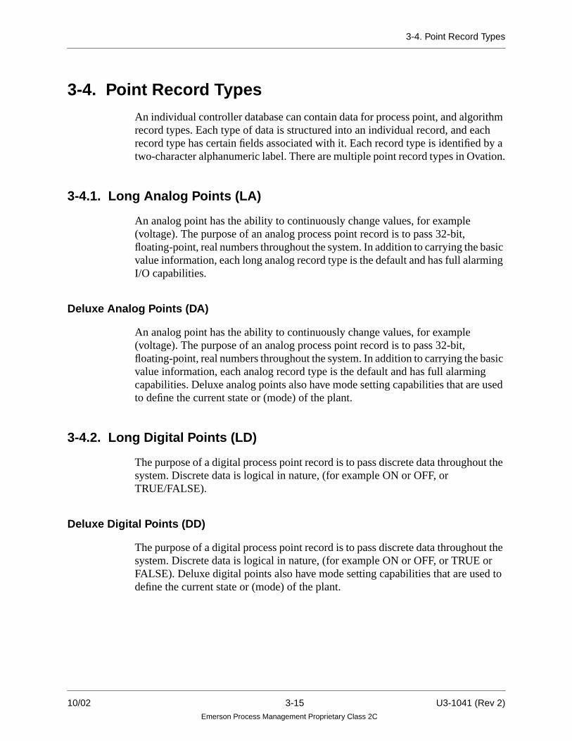
An individual controller database can contain data for process point, and algorithmrecord types. Each type of data is structured into an individual record, and eachrecord type has certain fields associated with it. Each record type is identified by atwo-character alphanumeric label. There are multiple point record types in Ovation.
3-4.1. Long Analog Points (LA)
An analog point has the ability to continuously change values, for example(voltage). The purpose of an analog process point record is to pass 32-bit,floating-point, real numbers throughout the system. In addition to carrying the basicvalue information, each long analog record type is the default and has full alarmingI/O capabilities.
Deluxe Analog Points (DA)
An analog point has the ability to continuously change values, for example(voltage). The purpose of an analog process point record is to pass 32-bit,floating-point, real numbers throughout the system. In addition to carrying the basicvalue information, each analog record type is the default and has full alarmingcapabilities. Deluxe analog points also have mode setting capabilities that are usedto define the current state or (mode) of the plant.
3-4.2. Long Digital Points (LD)
The purpose of a digital process point record is to pass discrete data throughout thesystem. Discrete data is logical in nature, (for example ON or OFF, orTRUE/FALSE).
Deluxe Digital Points (DD)
The purpose of a digital process point record is to pass discrete data throughout thesystem. Discrete data is logical in nature, (for example ON or OFF, or TRUE orFALSE). Deluxe digital points also have mode setting capabilities that are used todefine the current state or (mode) of the plant.
10/02 3-15 U3-1041 (Rev 2)Emerson Process Management Proprietary Class 2C

3-4. Point Record Types
3-4.3. Long Packed Points (LP)
Long Packed Points may be used to pack up to 16 discrete digital (logical) states inone point record. Each bit of the packed point may be separately configured for I/Oscanning. Additionally, the packed point can be configured for register - wideaddresses. Therefore, the user can configure all 16 bits by the specification of onlyone I/O location.
Deluxe Packed Points (DP)
Deluxe Packed Points may be used to pack up to 16 discrete digital (logical) statesin one point record. Each bit of the packed point may be separately configured forI/O scanning. Additionally, the packed point can be configured for register - wideaddresses. Therefore, the user can configure all 16 bits by the specification of onlyone I/O location.
Deluxe Packed Points also have mode setting capabilities that are used to define thecurrent state (mode) of the plant.
3-4.4. Packed Digital Points (PD)
The purpose of a packed digital process point record is to pass discrete data from anOvation Drop without any other information, such as alarming status or I/Oinformation. A packed digital point record contains either 32 separate digital valuesor two 16-bit register (analog) values. Packed digitals are frequently used to passinformation contained in special functions and in text algorithms.
3-4.5. Algorithm Points (LC)
The Algorithm Records are used to store tuning or data configuration for eachalgorithm in the system. Information is different for each algorithm.
3-4.6. Drop Points (DU)
The DU Record, (also known as a Drop Status Record), is automatically configuredin each Ovation drop. It is normally broadcast every 0.1 sec. The purpose inbroadcasting this record is to alert the system to any faults that may occur in aspecific drop and to show current status of the drop.
Standard status diagrams are designed to extract information from DU records.Normally, the status diagrams are sufficient to gather all pertinent data about thestatus of an individual drop.
U3-1041 (Rev 2) 3-16 10/02Emerson Process Management Proprietary Class 2C

3-4. Point Record Types
3-4.7. Module Points (RM)
The RM record is used to configure and monitor the status of Ovation I/O modules.
3-4.8. Node Points (RN)
RN records are used to configure and monitor PCRL, PCRR, PCRQ, and remoteI/O nodes.
10/02 3-17 U3-1041 (Rev 2)Emerson Process Management Proprietary Class 2C

3-5. Record Type Folder Tabs
3-5. Record Type Folder Tabs
The user can choose any individual tab to quickly navigate around the point and toview the related attributes. Any individual field can be modified at any time,although some fields may be “grayed-out” or not active, depending on the validityor contents of other fields. Any field that is modified by the user is automaticallychecked for validity when the cursor or mouse is moved away from it.
Note
If there is an error, a dialog box will pop up to warnthe user. The Add Point icon and menu item will bemade inactive until the error is corrected to preventinconsistency in the database.
The following record type point folders are available:
• LA (Long Analog) Record Type Point Folder (Section 3-5.1).
• DA (Deluxe Analog) Record Type Point Folder (Section 3-5.2).
• LD (Long Digital) Record Type Point Folder (Section 3-5.3).
• DD (Deluxe Digital) Record Type Point Folder (Section 3-5.4).
• LP (Long Packed) Record Type Point Folder (Section 3-5.5).
• DP (Deluxe Packed) Record Type Point Folder (Section 3-5.6).
• PD (Packed Digital) Record Type Point Folder (Section 3-5.7).
• LC (Algorithm) Record Type Point Folder (Section 3-5.8).
• DU (Drop) Record Type Point Folder (Section 3-5.9).
• RM (Module) Record Type Point Folder (Section 3-5.10).
• RN (Node) Record Type Point Folder (Section 3-5.11).
U3-1041 (Rev 2) 3-18 10/02Emerson Process Management Proprietary Class 2C

3-5. Record Type Folder Tabs
3-5.1. LA Record Type Point Folder
For an LA (Long Analog) record type (refer to Figure 3-13), the following tabs aredisplayed:
• Point
• Config
• Security
• Ancillary
• HSR
• Hardware
• Initial
• Alarm
• Instrumentation
• Limits
• Display
For information about the fields on each tab, refer to Appendix A.
Figure 3-13. LA Record Type Point Folder
10/02 3-19 U3-1041 (Rev 2)Emerson Process Management Proprietary Class 2C

3-5. Record Type Folder Tabs
3-5.2. DA Record Type Point Folder
For a DA (Deluxe Analog) record type (refer to Figure 3-14), the following tabs aredisplayed:
• Point
• Security
• Ancillary
• HSR
• Hardware
• Initial
• Alarm
• Instrumentation
• Limits
• Display
• Plant Mode
Figure 3-14. DA Record Type Point Folder
U3-1041 (Rev 2) 3-20 10/02Emerson Process Management Proprietary Class 2C

3-5. Record Type Folder Tabs
3-5.3. LD Record Type Point Folder
For an LD (Long Digital) record type (refer to Figure 3-15), the following tabs aredisplayed:
• Point
• Config
• Security
• Ancillary
• HSR
• Initial
• Alarm
• Hardware
• Display
For information about the fields on each tab, refer to Appendix A
Figure 3-15. LD Record Type Point Folder
10/02 3-21 U3-1041 (Rev 2)Emerson Process Management Proprietary Class 2C

3-5. Record Type Folder Tabs
3-5.4. DD Record Type Point Folder
For a DD (Deluxe Digital) record type (refer to Figure 3-16), the following tabs aredisplayed:
• Point
• Config
• Security
• Ancillary
• HSR
• Initial
• Alarm
• Display
• Hardware
• Plant Mode
For information about the fields on each tab, refer to Appendix A.
Figure 3-16. DD Record Type Point Folder
U3-1041 (Rev 2) 3-22 10/02Emerson Process Management Proprietary Class 2C
3-5. Record Type Folder Tabs
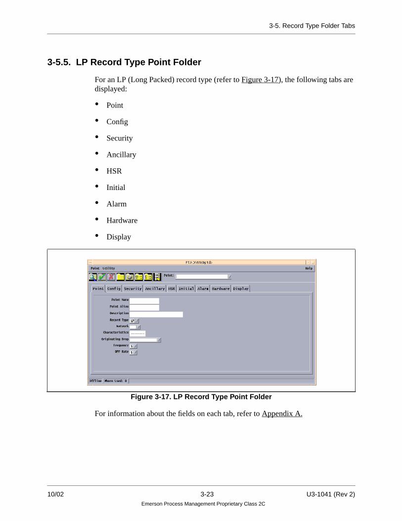
3-5.5. LP Record Type Point Folder
For an LP (Long Packed) record type (refer to Figure 3-17), the following tabs aredisplayed:
• Point
• Config
• Security
• Ancillary
• HSR
• Initial
• Alarm
• Hardware
• Display
For information about the fields on each tab, refer to Appendix A.
Figure 3-17. LP Record Type Point Folder
10/02 3-23 U3-1041 (Rev 2)Emerson Process Management Proprietary Class 2C

3-5. Record Type Folder Tabs
3-5.6. DP Record Type Point Folder
For a DP (Deluxe Packed) record type (refer to Figure 3-18), the following tabs aredisplayed:
• Point
• Config
• Security
• Ancillary
• HSR
• Initial
• Alarm
• Display
• Hardware
• Plant Mode
For information about the fields on each tab, refer to Appendix A.
Figure 3-18. DP Record Type Point Folder
U3-1041 (Rev 2) 3-24 10/02Emerson Process Management Proprietary Class 2C

3-5. Record Type Folder Tabs
3-5.7. PD Record Type Point Folder
For a PD (Packed Digital) record type (refer to Figure 3-19), the following tabs aredisplayed:
• Point
• Security
• Initial
• Display
• Ancillary
Figure 3-19. PD Record Type Point Folder
For information about the fields on each tab, refer to Appendix A.
Note
Ancillary Tab Fields must be created first, for the Ancillary Tab to display.
10/02 3-25 U3-1041 (Rev 2)Emerson Process Management Proprietary Class 2C

3-5. Record Type Folder Tabs
3-5.8. LC Record Type Point Folder
For an LC (Algorithm) record type (refer to Figure 3-20), the following tabs aredisplayed:
• Point
• Config
• Security
• Ancillary
• Byte Params
• Int Params
• Real Params
For information about the fields on each tab, refer to Appendix A.
Figure 3-20. LC Record Type Point Folder
U3-1041 (Rev 2) 3-26 10/02Emerson Process Management Proprietary Class 2C

3-5. Record Type Folder Tabs
3-5.9. DU Record Type Point Folder
For a DU (Drop) record type (refer to Figure 3-21), the following tabs are displayed:
• Point
• Config
• Security
• Ancillary
• HSR
• Alarm
• Display
For information about the fields on each tab, refer to Appendix A.
Figure 3-21. DU Record Type Point Folder
10/02 3-27 U3-1041 (Rev 2)Emerson Process Management Proprietary Class 2C

3-5. Record Type Folder Tabs
3-5.10. RM Record Type Point Folder
For an RM (Module) record type (refer to Figure 3-22), the following tabs aredisplayed:
• Point
• Config
• Security
• HSR
• Alarm
• Hardware
• Display
For information about the fields on each tab, refer to Appendix A.
Figure 3-22. RM Record Type Point Folder
U3-1041 (Rev 2) 3-28 10/02Emerson Process Management Proprietary Class 2C

3-5. Record Type Folder Tabs
3-5.11. RN Record Type Point Folder
For an RN (Node) record type (refer to Figure 3-23), the following tabs aredisplayed:
• Point
• Config
• Security
• HSR
• Alarm
• Hardware
• Display
For information about the fields on each tab, refer to Appendix A.
Figure 3-23. RN Record Type Point Folder
10/02 3-29 U3-1041 (Rev 2)Emerson Process Management Proprietary Class 2C

3-6. Creating a Point
3-6. Creating a Point
This is an example of creating a digital point but is applicable for all point types.Information on tabs and folders will vary for each record type. Before creating apoint, make sure the hardware has been set up correctly. Refer to “O vation I/OBuilder User Guide” (U3-1044).
The following example creates an LD record type.
1. From the Point Builder window, select the desired record type (LD in thisexample).
2. Access each tab and enter the desired information in the fields. See Appendix Afor a description of the tab fields.
3. Select the Add Point icon or select Add from the Point menu.
4. The Point is now in the database. If you want to put the point onto the highway,it must be loaded using the Ovation Drop Loader. (See “O vation Drop LoaderUser Guide” U3-1047).
Note
Using the Search window will be helpful whencreating points. You can choose an already existingpoint similar to the point you are creating, thenchange the applicable fields to create a new point.See Section 3-2.6 on accessing the Search window.
U3-1041 (Rev 2) 3-30 10/02Emerson Process Management Proprietary Class 2C

3-7. Modifying a Point
3-7. Modifying a Point
Use the following procedure to modify a point using the Point Builder:
1. From the Point folder select the Point tab.
2. Enter the Name of the point you want to modify.
3. Select the Drop Number from the Originating Drop pull-down menu.
4. From the Point folder, select the Security tab.
5. Select the appropriate Security information.
6. Make any other desired changes.
7. Select Add. Use the Point Menu icon from the Point Builder Main Window.
OR
Select Add from the Point pull-down Menu.
10/02 3-31 U3-1041 (Rev 2)Emerson Process Management Proprietary Class 2C

3-8. Deleting a Point
3-8. Deleting a Point
Use the following procedure to delete a point using the Point Builder.
1. Select the Point tab from the Point Folder.
2. Enter the Point Name you want to delete.
3. Select the Delete icon from the Point Builder Main Window.
OR
Select Delete from the Point drop-down Menu. This deletes the current pointdisplayed in the point folder.
3-9. Printing
Use the following procedure to print point information.
1. Select the Point tab from the Point Folder.
2. Enter the Point Name you want to print information about.
3. Select the Print icon from the Point Builder Main Window.
OR
Select Print from the Point drop-down Menu.
3-10. Generating HSR PIC Files
Use the following procedure to generate HSR PIC (Point Information Compiler)files.
1. Select the Generate HSR PIC files icon from the Point Builder Main Window.
OR
Select Generate HSR PIC files from the Utility drop-down Menu.
U3-1041 (Rev 2) 3-32 10/02Emerson Process Management Proprietary Class 2C

3-10. Generating HSR PIC Files
The HSR PIC File window appears as shown in Figure 3-24.
2. Select the desired Drop from the Drop pull down menu.
3. Select the desired Unit from the Net/Unit Filter scrolling list.
Note
If this field is blank and a Unit is not choosen, thegenerated PIC file will contain points from all Unitson all networks.
4. Select Generate to list all the files in the system.
5. Select Dismiss to close the window.
Figure 3-24. Point Builder Generate HSR PIC File Window
10/02 3-33 U3-1041 (Rev 2)Emerson Process Management Proprietary Class 2C

3-11. Checking Consistency
3-11. Checking Consistency
This will begin a consistency check on all the points in the database and will alertthe user of any applicable warnings.
1. Select the Consistency Checking icon from the Point Builder Main Window.
OR
Select Consistency Checking from the Utility pull-down Menu.
The Check Consistency Window appears.
2. Select Check and all the point inconsistencies from the database are listed.
3. Select Print to print all the inconsistencies listed.
4. Select Print Options to change the printer settings.
5. Select Dismiss to dismiss the window.
Figure 3-25. Point Builder Check Consistency Window
U3-1041 (Rev 2) 3-34 10/02Emerson Process Management Proprietary Class 2C

Section 4. Using the Point Group Builder
4-1. Section Overview
The Point Group Builder is used to create point groups used in trends or indiagrams. This procedure will build a global Point Group that will be distributed toall the system drops. Refer to “Ovation Operator Station User Guide” (U3-1031) forinformation about building local Point Groups (local to each drop and notdistributed).
4-2. Accessing the Point Group Builder
Use the following procedure to access the Point Group Builder from an EngineeringStation:
1. Select Point Group Builder from the Power Tools Menu.
Figure 4-1. Power Tools Menu
10/02 4-1 U3-1041 (Rev 2)Emerson Process Management Proprietary Class 2C

4-2. Accessing the Point Group Builder
2. The Point Group Builder window appears.
3. Refer to Table 4-1 for descriptions of the menus, fields, and buttons on the PointGroup Builder window.
Figure 4-2. Point Group Builder Window
Table 4-1. Point Group Builder Window
Menu Description
File Menu Quit - Selecting quit will exit the Point Group Builder.
View Menu HSR - Displays defined HSR groups.PDS - Displays defined PDS groups.Trend - Displays defined trend groups.
Display Menu Live trend - Displays selected trend groups.Historical trend - Displays historical trends for selected groups.
U3-1041 (Rev 2) 4-2 10/02Emerson Process Management Proprietary Class 2C

4-3. Modifying or Adding a Point Trend Group
4-3. Modifying or Adding a Point Trend Group
Use the following procedure to modify or add a global Point Trend Group.
1. Select the Trend Groups (default option) from the View pull-down button onthe Point Group Builder window.
2. A list of existing point Trend Groups appears in the Point Group Builderwindow. Select a group from the Group List. After selecting a group, all thepoints in the chosen group are listed in the scrolling list.
10/02 4-3 U3-1041 (Rev 2)Emerson Process Management Proprietary Class 2C

4-3. Modifying or Adding a Point Trend Group
3. Select Modify. The Trend Group Attributes window appears (Figure 4-3). Makethe desired changes. All fields can be modified except the Group Number.However, you cannot add more than eight points to a group.
The new point group is edited on line, therefore, the changes take effectimmediately in the Power Tools database and are automatically distributed tothe Operator Stations for inclusions in their distributed Power Tools databases.
OR
Select Add Group from the Point Group Builder window. The Trend GroupAttributes window appears (see Figure 4-3). When adding a Point Group, allfields appear blank. Select or enter the applicable information for the new TrendGroup. The new point group is added on line and the addition takes effectimmediately.
Note
The remainder of this section defines the fields that are used whenmodifying or adding a Point Trend Group. Some fields apply only tohistorical trends: History Type, Range, Start Time Offset, At, HistoryInterval, Processing Period. For information on defining an historical trendgroup, see “H istorian User Guide” (U3-1012).
Figure 4-3. Trend Group Attributes Window
U3-1041 (Rev 2) 4-4 10/02Emerson Process Management Proprietary Class 2C

4-3. Modifying or Adding a Point Trend Group
4. Enter a global group number (to define the group) in the Group Number field.The Group Number is used to identify group information.A maximum of 1,000 groups can be defined. If a group number is outside therange of 1 to 1,000 or the group number currently exists, the group is not added.
5. Enter the trend group name in the Name field, using up to 30 characters. Thetrend group name appears on the Trend Display icon, the Group scrolling list onthe Trend Groups window, and on the Trend Display window.
6. Enter the title of the trend group in the Title field, using up to 30 characters.
7. Pull down the Live Interval menu and select an interval. The collection intervalis the length of time of the trend display. The interval is specified as a numberof minutes, hours, or days. All points in a single window use the same collectioninterval.
10/02 4-5 U3-1041 (Rev 2)Emerson Process Management Proprietary Class 2C

4-3. Modifying or Adding a Point Trend Group
8. Pull down the Layout menu. Select a trend layout type.
• Horizontal Combined displays selected points in one graph, with timelocated on the horizontal axis. This trend updates from right to left.
• Vertical Combined displays selected points in one graph, with time locatedon the vertical axis. This trend updates from top to bottom.
• Vertical Side-By-Side displays selected points in up to eight vertical graphswith time located on the vertical axis. This trend updates from top to bottom.
• Quadrant displays selected points in four horizontal graphs in one window.
• X-Y Plot displays the value of one or more selected points (up to 7 pointsallowed) versus one other selected point in a line graph.
For additional information on historical trend groups, see “H istorian UserGuide” (U3-1012).
U3-1041 (Rev 2) 4-6 10/02Emerson Process Management Proprietary Class 2C

4-3. Modifying or Adding a Point Trend Group
9. If the trend layout is XY Plot, enter the percentage of plot samples to bedisplayed in the Live XY Plot (% percent) History field. The valid entries are 0to 100 where a value of 100% displays all 600 point values, and 0% does notdisplay values in the initial display of the plot or after a refresh of the screen.
Additionally the name of the reference curve can be entered from the GroupAttributes window if the XY Plot is selected.
Note
This field is only applicable to the XY Plot trendlayout. The reference curve is defined via the AdminTool.
10/02 4-7 U3-1041 (Rev 2)Emerson Process Management Proprietary Class 2C

4-3. Modifying or Adding a Point Trend Group
10. If the trend layout is Quadrant, enter a title for each quadrant trend in theQuadrant A through D Title fields. Up to 30 characters may be entered for eachtitle. The titles will appear above each quadrant trend.
Note
These fields are only applicable to the Quadrant trendlayout.
11. Pull down the Grid menu. This option displays or removes grid lines on thetrend graph.
U3-1041 (Rev 2) 4-8 10/02Emerson Process Management Proprietary Class 2C

4-3. Modifying or Adding a Point Trend Group
12. If the continuous Rate Change option is enabled, the Continuous Rate ofChange option is shown in the window. Pull down the Continuous Rate ofChange menu. Select an option.
• None will disable the Continuous Rate of Change display on the trend.
• 3 Samples will display an updating value on the trend window. The value isthe rate of change between the current point sample value and the valuethree samples before the current sample.
• 30 Samples will display an updating value on the trend window. The valueis the rate of change between the current point value and the value thirtyvalues before the current sample.
• Both will display both the sample and the thirty sample continuous rate ofchange on the trend.
Note
Continuous Rate Change is enabled or disabled usingthe Admin Tool on the Miscellaneous Parametersdisplay of the MMI Trend Configuration GUI.
10/02 4-9 U3-1041 (Rev 2)Emerson Process Management Proprietary Class 2C

4-3. Modifying or Adding a Point Trend Group
See “Using the Ovation Init and Admin Tools”(R3-1105) for instructions on using the Admin Toolto select the MMI Trend Configuration GUI.
13. To copy existing information from another Group select Copy From Groupfrom the Group Attributes Window. The Select A Group window appears asshown in Figure 4-4.
Apply - Copies the selected group and dismisses the window.
Cancel - Quits the window.
Help - On line help for the applicable window.
14. To enter live (or historical) information about the trend currently displayed inthe window, select the Fill Info from Trend button.
Note
Make sure the currently displayed trend is also theselected trend (that is, the trend window has itscheckbox selected).
15. To modify an existing point, select a point from the scrolling list and then selectModify from the Group Attributes window as shown in Figure 4-3.
Figure 4-4. Select A Group Window
U3-1041 (Rev 2) 4-10 10/02Emerson Process Management Proprietary Class 2C

4-3. Modifying or Adding a Point Trend Group
16. To delete one of the point entries, select the box which has the point to bedeleted. The name of the point will appear in the Name entry field. Delete thepoint name by selecting the Delete key.
17. To add a point, select Add Point from the Group Attributes window as shownin Figure 4-3. The Point Attributes Window appears (as shown in Figure 4-5).
The new point group is added (or edited) on-line, therefore, the changes takeeffect immediately in the Power Tools database and are automaticallydistributed to the Operator Stations for inclusions in their distributed PowerTools databases.
18. Enter the desired point name in the Name entry field.
19. Enter a subgroup (A-H) in the Subgroup field. The Subgroup field is used tospecify groupings on Vertical Side-by-Side and Quadrant trends:
• Vertical Side-by-Side (range = A to H). There is one vertical trend displayedfor each subgroup that has at least one point assigned to it. Multiple pointswithin the same subgroup are displayed in the same vertical trend.
Figure 4-5. Point Attributes Window
10/02 4-11 U3-1041 (Rev 2)Emerson Process Management Proprietary Class 2C

4-3. Modifying or Adding a Point Trend Group
• Quadrant (range = A to D). There is one quadrant trend for each subgroup. Fourquadrant trends are displayed in a single window. A subgroup outside the rangeof A to D will give an error, and the point will not be displayed.
20. Enable the Shading to use the Baseline field. Shading indicates that the areabetween the baseline and the trend line is shaded.
21. Enter the baseline value (up to 8 digits) in the Baseline field. The Baseline fieldis applicable to all trend layouts except for xy plots. All points in a trend havean independent baseline. The area between the trend line and the baseline isshaded with the same color as the trend line. To disable baseline shading, selectDisable from the Shading menu.
The first point position in the trend has top priority when shading is present. Thelast point position has the lowest priority.
• The point high scale value becomes the baseline when the baseline is greaterthan the point high scale.
• The point low scale value becomes the baseline when the baseline is lessthan the point low scale.
• For logarithmic points, the baseline value must be greater than zero.
U3-1041 (Rev 2) 4-12 10/02Emerson Process Management Proprietary Class 2C

4-3. Modifying or Adding a Point Trend Group
22. Pull down the Scale Limits menu. This option enables the user to view a trendline in lesser or greater detail. Each trend point has its own set of temporary highand low scales.
The scale limits allow the operator to select Default, User Entered or AutomaticScaling. Automatic Scaling is an optional choice and must be enabled in thesystem configuration.
Note
Automatic Scaling is Enabled or Disabled using theAdmin Tool on the Miscellaneous Parametersdisplay of the MMI Trend Configuration GUI.
See “Using the Ovation Init and Admin Tools”(R3-1105) for instructions on using the Admin Toolto select the MMI Trend Configuration GUI.
10/02 4-13 U3-1041 (Rev 2)Emerson Process Management Proprietary Class 2C

4-3. Modifying or Adding a Point Trend Group
When Automatic Scaling is not enabled, the scale limit choices are Default andUser Entered. The operator will be able to select the type (linear or logarithmic),and enter in the high and low scale limits, which are used to draw the trend lines.If the limits are not User Entered, the type menu and the high and low limit fieldsare deactivated (greyed out) and not used to draw the trend lines.
• Default displays the scale values for the point using the scales listed in thetrend_defaults_file, or the TV (maximum scale value) and BV (minimumscale value) for analog points (as described in “Ovation Record TypesReference Manual” (R3-1140).
• User Entered enables the temporary scale for one point.
• Automatic enables automatic scaling for one point. When Automatic isselected, the scale values are updated periodically according to the valuescurrently displayed on the trend.
23. If desired, enter the temporary scale values in the High and Low entry fields.
U3-1041 (Rev 2) 4-14 10/02Emerson Process Management Proprietary Class 2C

4-3. Modifying or Adding a Point Trend Group
• High Scale represents the top boundary of the trend. The high scale must berepresented as a positive or negative integer, floating point, or in scientificor technical notation. For example, scientific (1.0e2, -1.0E+2, 1.0E-2)technical (100e0, 10e3, 10E6).
• Low Scale represents the bottom boundary of the trend. The low scale mustbe represented as a positive or negative integer, floating point, or in scientificor technical notation. For example, scientific (1.0e2, -1.0E+2, 1.0E-2)technical (100e0, 10e3, 10E6).
Note
If Default scales are used, the scales defined in thetrend_defaults_file are used. If the point is not defined inthe trend_defaults_file, the trend will use TV (maximumscale value) and BV (minimum scale value) for analogpoints (as described in “Ovation Record Types ReferenceManual” (R3-1140).
The trend will use the values defined by Digital DefaultHigh Scale and Digital Default Low Scale for digitalpoints. The digital default scales are located in theAdmin Tool on the Miscellaneous Parameters display ofthe MMI Trend Configuration GUI.
See “Using the Ovation Init and Admin Tools”(R3-1105) for instructions on using the Admin Tool toselect the MMI Trend Configuration GUI.
Digital points differ from analog points in that digital points always have a valueof 0 (off) or 1 (on). The high and low scale values specified for digital pointsindicate the position of the trend line on the window and the height of the trend.For more information, see R3 -1105.
10/02 4-15 U3-1041 (Rev 2)Emerson Process Management Proprietary Class 2C

4-3. Modifying or Adding a Point Trend Group
24. Pull down the Type menu. (The Type menu is active only when the Scale Limitsare enabled). Select a linear or logarithmic scale.
Note
When a Logarithmic scale is selected and TemporaryScales are enabled, the high scale and low scalevalues must be greater than zero.
25. Pull down the Transient menu. Selecting Yes causes the second digital averagevalue (0 or 1) of any 3 consecutive values in the trend data that are the same tobe changed to the opposite state if the second digital average value was not inthe same state for its entire processing period.
The transient option does not show true data, and is meant to bring out digitalstate changes that would otherwise remain hidden on trends of digital points forprocessing periods greater than 1 second.
A trend around the time of the digital activity should be performed, with theprocessing period decreased and the transient option disabled to show the truedigital states. (This option is applicable only when the processing type isAverage Value).
U3-1041 (Rev 2) 4-16 10/02Emerson Process Management Proprietary Class 2C

4-3. Modifying or Adding a Point Trend Group
26. Pull down the Summary menu. Select Yes to include a summary section or Noto exclude a summary section. The summary consists of data for each point,such as averages, maximums, and minimums.
27. Pull down the Processing Type menu, and select an applicable type. The typesare as follows:
• Actual Value displays the actual value of the specified process point at theend of each individual processing period.
• Unpacked Bit Value displays the actual value of a selected bit of thespecified process point at the end of each individual processing period.
• Average displays the average value of the specified process point over eachindividual processing period.
• Maximum Value displays the maximum value of the specified processpoint over each individual processing period.
• Minimum Value displays the minimum value of the specified process pointover each individual processing period.
• Integration displays the integral of the specified process point with respectto seconds, multiplied by the specified integration constant, over eachindividual processing period.
• Toggle displays the number of state changes for the specified digital processpoint, or selected bit of a packed process point, which occurred over eachindividual processing period.
• Toggle Set displays the number of state changes to the Set state for thespecified digital process point, or selected bit of a packed process point,which occurred over each individual processing period.
• Toggle Reset displays the number of state changes to the Reset state for thespecified digital process point, or selected bit of a packed process point,which occurred over each individual processing period.
• Time Set Mins displays the number of minutes which the specified digitalprocess point, or selected bit of a packed process point, spent in the Set stateover each individual processing period.
• Time Reset Mins displays the number of minutes which the specifieddigital process point, or selected bit of a packed process point, spent in theReset state over each individual processing period.
10/02 4-17 U3-1041 (Rev 2)Emerson Process Management Proprietary Class 2C

4-3. Modifying or Adding a Point Trend Group
• Time Set Hours displays the number of hours which the specified digitalprocess point, or selected bit of a packed process point, spent in the Set stateover each individual processing period.
• Time Reset Hours displays the number of hours which the specified digitalprocess point, or selected bit of a packed process point, spent in the Resetstate over each individual processing period.
28. Enter the integration constant, in the Integration Constant field. This field isonly applicable when the processing type is Integration.
29. Select Apply to add the modified or created Point Group to the Group List.
30. Repeat Steps 13 - 29 until all point information has been entered.
31. When all information for the point has been entered, select the OK or Applybutton.
• To return data in this window to the last applied entries, select the Resetbutton.
The currently selected point name and temporary scale values are checked forsyntax errors. LOG point scales are checked for invalid values less than or equalto zero. The slot number and the subgroup entries are checked to verify thevalues are in the correct range.
Since trend groups are used for both historical and live trends, there is no checkto see if the points are defined in the System Point Directory or if they are validfor trending. This is because the Historian drop can trend points that are not inthe current point directory. (Once a point has been broadcast by a Controller andstored in the Historian, subsequent point directory reprogramming will have noeffect on that point, as far as trending is concerned).
U3-1041 (Rev 2) 4-18 10/02Emerson Process Management Proprietary Class 2C

4-4. Modifying or Adding an HSR Point Group
4-4. Modifying or Adding an HSR Point Group
Use the following procedure to modify or add a global Point HSR Group.
1. Select the HSR Groups from the View pull-down button on the Point GroupBuilder window.
10/02 4-19 U3-1041 (Rev 2)Emerson Process Management Proprietary Class 2C

4-4. Modifying or Adding an HSR Point Group
2. A list of existing point groups appears in the Point Group Builder window.Select a group from the Group List. After selecting a group, all the points in thechosen group are listed in the scrolling list.
U3-1041 (Rev 2) 4-20 10/02Emerson Process Management Proprietary Class 2C

4-4. Modifying or Adding an HSR Point Group
3. Select Modify. The HSR Group Attributes Window appears (see figure below).Make the desired changes. All fields can be modified except the Group Number.However, you cannot add more than eight points to a group.
OR
Select Add Group from the Point Group Builder window. The HSR GroupAttributes window appears (see Figure 4-6). When adding a Point Group, allfields appear blank. Select or enter the applicable information for the new HSRPoint Group.
Figure 4-6. HSR Group Attributes Window
10/02 4-21 U3-1041 (Rev 2)Emerson Process Management Proprietary Class 2C

4-5. Modifying or Adding a PDS Point Group
4. Enter a global group number (to define the group) in the Group Number field.The Group Number is used to identify group information.A maximum of 1,000 groups can be defined. If a group number is outside therange of 1 to 1,000 or the group number currently exists, the group is not added.
5. Enter the group name in the Name field.
6. Enter the title of the HSR group in the Title field, using up to 30 characters.
7. Enter the desired point names in the Point Name field. Although there are onlyeight point entry fields displayed, up to 250 points can be entered in a group.
8. Select the Add Point button. The new point group is added (or edited) on-line.Therefore, the changes take effect immediately in the Power Tools database andare automatically distributed to the Operator Stations for inclusions in theirdistributed Power Tools databases.
9. Select Apply to add the modified or created Point Group to the Group List.
10. To return the fields to the last applied change, select the Reset button.
4-5. Modifying or Adding a PDS Point Group
Use the following procedure to modify or add a PDS Point Group.
1. Select PDS Groups from the View pull-down button on the Point GroupBuilder window.
U3-1041 (Rev 2) 4-22 10/02Emerson Process Management Proprietary Class 2C

4-5. Modifying or Adding a PDS Point Group
2. A list of existing PDS Point Groups appears in the Point Group Builderwindow. Select a group from the Group List. After selecting a group, all thepoints in the chosen group are listed in the scrolling list.
3. Select Modify. The PDS Group Attributes window appears (see figure below).Make the desired changes. All fields can be modified except the Group Number.However, you cannot add more than eight points to a group.
10/02 4-23 U3-1041 (Rev 2)Emerson Process Management Proprietary Class 2C

4-5. Modifying or Adding a PDS Point Group
OR
Select Add Group from the Point Group Builder window.The PDS Group Attributes window appears (see Figure 4-7).When adding aPoint Group, all fields appear blank. Select or enter the applicable informationfor the new PDS Group.
4. Enter a global group number (to define the group) in the Group Number field.The Group Number is used to identify group information. A maximum of 1,000 groups can be defined. If a group number is outside therange of 1 to 1,000 or the group number currently exists, the group is not added.
5. Enter the group name in the Name field.
6. Enter the title of the PDS group in the Title field, using up to 30 characters.
7. The Diagram Number field displays the number of the diagram to be loadedwhen this point group is loaded. If this field is left blank or set equal to zero,then the requested group is displayed with the current diagram. If this field isnon-zero, then the diagram of that number will be displayed with the requestedgroup.
8. The Text Group Number field allows the user to attach additional text stringsto the Point Group when displaying a diagram. The valid range is 1 to 5000.Each Text Group may contain up to 100 text strings.
Figure 4-7. PDS Group Attributes Window
U3-1041 (Rev 2) 4-24 10/02Emerson Process Management Proprietary Class 2C

4-5. Modifying or Adding a PDS Point Group
9. The Group Paging fields (Left, Right, Up, Down) allow the user to enter thegroup numbers associated with this group to be used for paging. Enter the groupnumbers in the Group Paging fields.
A paging group number must be an integer from 0 to 6,000. If the value isoutside this range, the default value of zero is used, indicating no paging in thatdirection.
10. Enter desired text in the String fields.
11. Enter the desired point names in the Point Name field. Although there are onlyeight point entry fields displayed, up to 250 points can be entered in a group.
12. Select the Add Point button. The new point group is added (or edited) on-line.Therefore, the changes take effect immediately in the Power Tools database andare automatically distributed to the Operator Stations for inclusions in theirdistributed Power Tools databases.
13. Select Apply to add the modified or created Point Group to the Group List.
14. To return the fields to the last applied change, select the Reset button. Thetemporary point group file is accessed for the point group data.
10/02 4-25 U3-1041 (Rev 2)Emerson Process Management Proprietary Class 2C


Appendix A. Descriptions of Tab Fields
A-1. Section Overview
This Appendix lists the Point Builder Folders’ Tabs, Fields and their descriptions.
Information on tabs and folders will vary for each record type. Refer to R3-1140 foradditional information on point record types.
This section contains the following descriptions:
Note
In the following Tab Field descriptions:
Bits are numbered (0 - 15).
Channels are numbered (1 - 16). If a channel is not used, set to Zero (0).
• Point Tab Descriptions Appendix A-2
• Config Tab Descriptions Appendix A-3
• Security Tab Descriptions Appendix A-4
• Ancillary Tab Descriptions Appendix A-5
• HSR Tab Descriptions Appendix A-6
• Initial Tab Description Appendix A-7
• Alarm Tab Descriptions Appendix A-8
• Hardware Tab Descriptions Appendix A-9
• Display Tab Descriptions Appendix A-10
• Byte Params Tab Descriptions Appendix A-11
• Instrumentation Tab Descriptions Appendix A-12
• Int Params Tab Descriptions Appendix A-13
• Real Param Tab Descriptions Appendix A-14
• Plant Mode Tab Description Appendix A-15
• Limits Tab Descriptions Appendix A-16
10/02 A-1 U3-1041 (REV 2)Emerson Process Management Proprietary Class 2C

A-2. Point Tab Descriptions
A-2. Point Tab Descriptions
Tab Field Description
Point Point Name Represents the name of the point.Refer to Section 1-6 for point name rules.
Point Alias Sixteen character alias for the point name.
Description This maps directly to the ED field of the point record.
Record Type Represents the record type of the point.
Network This is the network identification for the point. It must represent a validnetwork as defined in the net_master table. It is used to form the systemidentifier for the point, as well as for a fully qualified point name.(point name.unit@network)- This field cannot be changed as its value isdictated by the point’s originating drop.
Characteristics This maps directly to the KR field of the point record, with the first charactermapping directly to the AY field (destination) of the point record.Up to eight alphanumeric characters can be used.
OriginatingDrop
Identifies the Point’s originating drop.
U3-1041 (Rev 2) A-2 10/02Emerson Process Management Proprietary Class 2C

A-2. Point Tab Descriptions
Point(Con’t)
Frequency This field represents the broadcast frequency of the point. The choices are:S (S)low 1.0F (F)ast 0.1A (A)periodic as requested
NoteAperiodic points will be broadcast in special aperiodic DDBs. These will bebroadcast on the highway by subscription. When a point’s dynamic data isaccessed from another drop, that drop will send a request to the originator tostart broadcasting (once a second) the DDB containing the point. Thesesubscriptions are renewed with the subsequent accesses. Once thesubscription runs out, the point (DDB) will no longer be broadcast.
OPP Rate This field defines the processing rate for alarm and limit checking of thepoint.S (S)low 1.0 secondF (F)ast 0.1 secondA (A)periodic as requestedU (U)ser defined
Drop number This is the drop number of the originating drop of the point. Valid entriesare 1-254.
Unit This is the unit identifier for the point. It must represent a valid unit asdefined in the unit_master table. A value of zero is used for projects that donot use units.
This is the network identification for the point. It must represent a validnetwork as defined in the net_master table. It is used to form the systemidentifier for the point, as well as for a fully qualified point name.(point name.unit@network)- This field cannot be changed as its value isdictated by the points originating drop.
Tab Field Description(Con’t)
10/02 A-3 U3-1041(Rev 2)Emerson Process Management Proprietary Class 2C

A-3. Config Tab Descriptions
A-3. Config Tab Descriptions
Tab Field Description
Config Partner drop This field identifies the drop ID of the partner drop.
Alarm group mask Determines which bits of the packed point will alarm.
Alarm group bit sense Determines the alarm state of each bit in the packed point that has a bitset in the alarm group mask.
Register C, D, Econfiguration data
Configuration registers C,D,E are used for configuring RM and RNrecords. The meaning of the bits changes based on the module type.These bits should not be changed with the Point Builder, instead the I/OBuilder should be used to configure the modules.
Register C,D, Econfiguration mask
Configuration registers C,D,E are used for configuring RM and RNrecords. The meaning of the bits changes based on the module type.These bits should not be changed with the Point Builder, instead the I/OBuilder should be used to configure the modules.
Index register 1, 2, 3(Also known as indexnumber)
Part of Electronic ID. Provides a description of the type and revision ofcards that make up an Ovation module or Controller.
Consists of three 16-bit integers (words).Refer to R3-1150 for additional information about the electronic ID.
U3-1041 (Rev 2) A-4 10/02Emerson Process Management Proprietary Class 2C

A-3. Config Tab Descriptions
.
Config(Cont’d)
Configurationfilename
This maps to the FN field of RM records.
New Alarm/LimitConfiguration:Auto Reset
Auto Acknowledge
If this bit is set, the point will be automatically reset.
If this bit is set, the point will be automatically acknowledged.
Oscillation count(counts/min)
Indicates the number of oscillations allowed before the point entersoscillation alarm. Must be a valid integer in the range 0 through 65535.
Inverted The value read from or written to the I/O cards is inverted if thecorresponding bit is set in this field.
Power Check:Power check enablefor bits
Power check channel(bit 1-16)Power check enable
Used for the power check function for packed points.
Used for the power check function for packed points.
This field enables the power check.
Tunable This field defines whether or not the algorithm is tunable.
Tuning diagram This field defines the number of the applicable tuning diagram.
Algorithm name This field represents the name of the algorithm.
Reset sum This maps directly to bit 2 of the EQ field of the point record.
Status checking type N = no status checking0 = alarm on 01= alarm on 12 = state change only3 = alarm in transition from 0 to14 = alarm in transition from 1 to 0
Relay close delay time(msec)
This field is used to set the relay close delay time, in milliseconds.
SOE:SOE point
SOE 1 shot algorithm
SOE reporting option
This field is used to establish that the point is an SOE point.
This field maps directly to bit 3 of the EQ field.
This maps directly to the bits 5 and 6 of the EQ field of the point record
Tab Field Description(Con’t)
10/02 A-5 U3-1041(Rev 2)Emerson Process Management Proprietary Class 2C

A-4. Security Tab Descriptions
A-4. Security Tab Descriptions
Tab Field Description
Security Security group(1-32)
These columns represent the security group(s) to which a point may beassigned.
U3-1041 (Rev 2) A-6 10/02Emerson Process Management Proprietary Class 2C
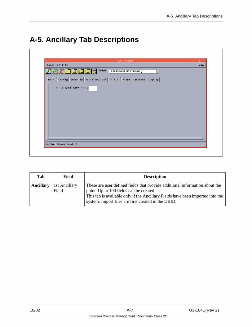
A-5. Ancillary Tab Descriptions
A-5. Ancillary Tab Descriptions
Tab Field Description
Ancillary 1st AncillaryField
These are user defined fields that provide additional information about thepoint. Up to 100 fields can be created.This tab is available only if the Ancillary Fields have been imported into thesystem. Import files are first created in the DBID.
10/02 A-7 U3-1041(Rev 2)Emerson Process Management Proprietary Class 2C

A-6. HSR Tab Descriptions
ichichory
on
A-6. HSR Tab Descriptions
Tab Field Description
HSR Collection:CollectionenabledHistory type:MAINLONGTERMLAB_DATA
Scan Frequency
Specifies if a point will be collected by HSR.The HISTORY attribute assignment specifies the HSR Station subsystem whis to process the point for collection, storage and retrieval. The subsystems whallow point assignments to be specified are the Main, Long Term, and LaboratData.
Frequency (in seconds) at which specific point will be scanned by the HSR the Highway to determine if it meets collection criteria.
U3-1041 (Rev 2) A-8 10/02Emerson Process Management Proprietary Class 2C
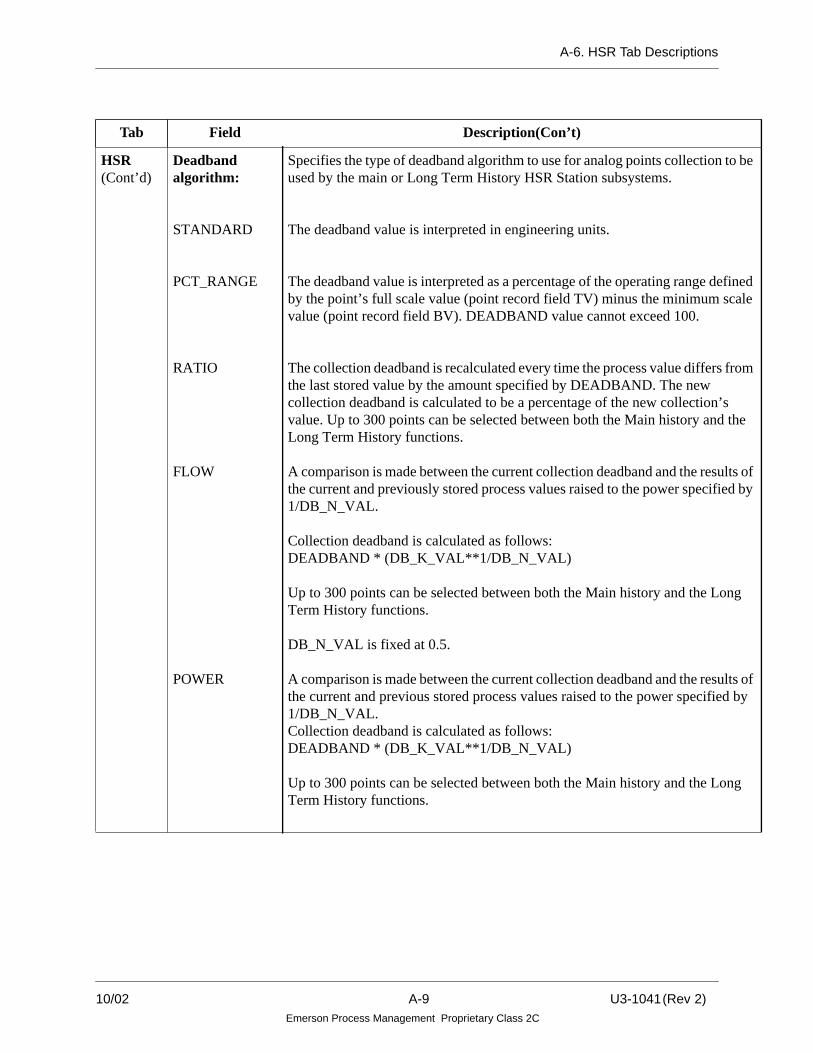
A-6. HSR Tab Descriptions
be
nedale
om
he
s ofby
g
s ofby
g
HSR(Cont’d)
Deadbandalgorithm:
STANDARD
PCT_RANGE
RATIO
FLOW
POWER
Specifies the type of deadband algorithm to use for analog points collection toused by the main or Long Term History HSR Station subsystems.
The deadband value is interpreted in engineering units.
The deadband value is interpreted as a percentage of the operating range defiby the point’s full scale value (point record field TV) minus the minimum scvalue (point record field BV). DEADBAND value cannot exceed 100.
The collection deadband is recalculated every time the process value differs frthe last stored value by the amount specified by DEADBAND. The newcollection deadband is calculated to be a percentage of the new collection’svalue. Up to 300 points can be selected between both the Main history and tLong Term History functions.
A comparison is made between the current collection deadband and the resultthe current and previously stored process values raised to the power specified1/DB_N_VAL.
Collection deadband is calculated as follows:DEADBAND * (DB_K_VAL**1/DB_N_VAL)
Up to 300 points can be selected between both the Main history and the LonTerm History functions.
DB_N_VAL is fixed at 0.5.
A comparison is made between the current collection deadband and the resultthe current and previous stored process values raised to the power specified 1/DB_N_VAL.Collection deadband is calculated as follows:DEADBAND * (DB_K_VAL**1/DB_N_VAL)
Up to 300 points can be selected between both the Main history and the LonTerm History functions.
Tab Field Description(Con’t)
10/02 A-9 U3-1041(Rev 2)Emerson Process Management Proprietary Class 2C

A-6. HSR Tab Descriptions
g
g
HSR(Cont’d)
Deadbandalgorithm:RADIATION
LOG
Deadband value
DB_K_VALvalue
DB_N_VALvalue
A comparison is made between the current collection deadband and thelogarithms of the current and previously stored process values.Collection deadband is calculated as follows:DEADBAND * DB_K_VAL
Up to 300 points can be selected between both the Main history and the LonTerm History functions.
DB_N_VAL is fixed at 10.0
A comparison is made between the current collection deadband and thelogarithms of the current and previously stored process values.Collection deadband is calculated as follows:DEADBAND * DB_K_VAL
Up to 300 points can be selected between both the Main history and the LonTerm History functions.
Specifies how deadband is used:- Interpreted as a value in engineering units.- Interpreted as percentage of point’s range.- Calculated as ratio of previously stored value.- As an argument in calculating logarithmic or exponential deadbands.
Specifies a value for the K value which is used by the special deadbandalgorithms FLOW, POWER, RADIATION, and LOG for analog points.
Specifies a value for the N value which is used by the special deadbandalgorithms POWER and LOG for analog points.
Tab Field Description(Con’t)
U3-1041 (Rev 2) A-10 10/02Emerson Process Management Proprietary Class 2C

A-6. HSR Tab Descriptions
ory
vente
vent
ventrip
n the
oint
s
up to
useigger.
o be
at it
Tab Field Description (Con’t)
HSR(Cont’d)
Deadbandalgorithm:Event:Event collected
Event trip point
Trip sense
Trip mask
Trip bit sense
This field specifies that the point will be collected by the HSR Event Historysubsystem.
This field specifies that the point will be defined as a trigger for the Event Histsubsystem.
Applicable for digital points, and if the point is defined as a trip point (that is, Etrip point is selected), this is the state (0 or 1) the point must go to in order to brecognized as a trip.
Applicable for packed points, and if the point is defined as a trip point (that is, Etrip point is selected), this indicates which bits contribute toward a trip.
Applicable for packed points, and if the point is defined as a trip point (that is, Etrip point is selected), this indicates the state of the bits (0 or 1) specified by “Tmask” that the point’s value must go to in order to be recognized as a trip.
SOE: Enabled This parameter specifies that the point is collected by the SOE subsystem.
Scan frequency Frequency (in seconds) at which a specific point will be scanned by the HSR oHighway to determine if it meets collection criteria.
Trigger number There can be up to three digital points configured as trigger points.
Trigger state If a state is defined as a trigger state for a trigger number, this is the state the pmust go to in order for a trigger to occur.Can be a 0, 1, or X (value of x indicates the value doesn’t matter, just that it hachanged state).
Trigger causes Defines the trigger point (1,2, or 3) this point is associated with. There can be 128 points configured as a trigger causes for each of the three trigger points.The printed SOE trip report identifies the point that was the first-out trigger cawhen the trigger occurred. This point is then considered to be the cause of the tr
Trigger 1, 2, 3cause state
If state is defined as a trigger state, this is the state the point must go in order trecognized as a trigger.Can be 0, 1, or X (X value doesn’t care what state point has changed to, just thhas changed state).
10/02 A-11 U3-1041(Rev 2)Emerson Process Management Proprietary Class 2C

A-7. Initial Tab Descriptions
r
.
A-7. Initial Tab Descriptions
Tab Field Description
Initial Initial status:Periodic save
This field represents whether or not the value of the point should beperiodically saved to flash (not applicable for packed digital points).
Tagout This field establishes the initial tagout state for the point. Not applicable fopacked digital points. For packed points, there is an initial tagout state foreach of the 16 bits.
Uncommisioned This field establishes the Uncommisioned state of the point (not applicablefor packed digital points).For packed points there is an Uncommisioned state for each of the 16 bits
Bit (0-15):Value (0-15)
For packed points, the initial value condition for each bit.
Value (0-31) For Packed digital points, the initial value condition for each bit.
InitialConditions:Value This field establishes the initial first pass value of the point.
U3-1041 (Rev 2) A-12 10/02Emerson Process Management Proprietary Class 2C

A-8. Alarm Tab Descriptions
A-8. Alarm Tab Descriptions
10/02 A-13 U3-1041(Rev 2)Emerson Process Management Proprietary Class 2C

A-8. Alarm Tab Descriptions
e
s
e
s
s.
s,er
s.
P)
Tab Field Description
Alarm Normal:Alarm delaytime
This field sets the initial alarm delay time, in seconds. This delay is the timbetween the alarm being detected and being reported in alarm.Valid timeentry is from 0 to 65535 seconds. This field does not apply to sensor alarmsince they never delay or cutout from reporting.
Cutout:Alarm cutoutdelay time
Alarm cutoutname
Alarm cutoutbit (0 - 15)
This field sets the alarm cutout delay time, in seconds. This delay is the timafter the cutout is released before the alarm is actually reported.
This field is the point used as a cutout for the base point (digital or packedpoint).
If the Alarm Cutout is a packed point, the bit number that is entered in thifield is mapped to bits 28-32 of the SJ field.
Priorities:
Low alarmpriority 1-4
Low alarm userpriority
High alarmpriority 1-4
High alarm userpriority
Alarm priority
Analog points can have up to 5 different high and 5 different low prioritieThe priority may be from 1 to 8, where 1 is the most critical alarm. Thepriority should be defined only if the corresponding limit is defined: that iHigh Limit 1 to 4 and High User Alarm, and Low Limit 1 to 4 and Low UsAlarm.
Sensor and SID alarms use the highest value from all of the defined prioritieReturns use the lesser value of all defined priorities.
These fields map to the various alarm priority fields of the point record. (AP, P6, P7, P8)
This field maps to the user alarm priority field of the point record. (P9)
These fields map to the various alarm priority fields of the point record.(AP, P6, P7, P8)
This field maps to the user alarm priority fields of the point record. (P9)
These fields map to the various alarm priority fields of the point record. (A
U3-1041 (Rev 2) A-14 10/02Emerson Process Management Proprietary Class 2C

A-9. Hardware Tab Description
A-9. Hardware Tab Description
10/02 A-15 U3-1041(Rev 2)Emerson Process Management Proprietary Class 2C

A-9. Hardware Tab Description
Tab Field Description
Hardware I/O Channel(1 - 16)
This field maps directly to the HD field of the pointrecord. It is used with the base address of the card actualI/O hardware. Also used for digital or packed pointsassociated with third party I/O.
I/O Module This field indicates which specific I/O location the pointis assigned to.
I/O Task Index(Control Task)
This field represents the processing task index used bythe controller. Points are grouped by the Control taskindex so that they can be updated (scanned) at differentrates. The Control task rate is set by the Admin Tool inthe Controller Configuration Parameters dialog box(described in the “Ovation Controller User Guide”(U3-1032).
Control Task 1 = 100 msecControl Task 2 = 1000 msec (1 second)Control Tasks 3, 4, and 5 are user configurable and thescan rate should be for the application and system needs.
It is recommended that the third party points be giventheir own task area. The scan rate should be no fasterthan one second because of the communicationoverhead.
No more than 2000 points can be assigned to a task area.
I/O Type This field determines the I/O type of the point:Q=Q-LineR=R-Line (Ovation)T= Third-Party deviceNull if the point is not an I/O point.
U3-1041 (Rev 2) A-16 10/02Emerson Process Management Proprietary Class 2C

A-9. Hardware Tab Description
Hardware(Con’t)
I/O Access Path Text string description of the address of a register in aThird-Party device. For example,
AB PLC5 2 IN N7:02
Where:
AB = Allen Bradley TCP/IP driverPLC5 = PLC5 communication protocol2 = Connect to hostname “plc5-2”IN = Read AB register to process pointN7:02 = A-B register address
Third party devices include:Allen Bradley TCP/IPRTP I/OModbusGE Mark VGE Mark VI
Packed points (LP) have 16 IO Access paths, one foreach bit. The bit number should be zero (0) in all 16 IOAccess paths. All 16 paths should be identical. TheController treats each bit as a separate point if the accesspaths are different.
Tab Field Description
10/02 A-17 U3-1041(Rev 2)Emerson Process Management Proprietary Class 2C

A-9. Hardware Tab Description
Hardware(Con’t)
Sensor:Relay Module
Contact type
Refer to R3-1150 (Ovation) or M0-0053 (Q-Line) formodule information.
N_OPEN (normally open)N_CLOSED (normally closed)FORMX1_FORMC (normally open)1_FORMCO (normally open)1_FORMCC (normally closed)2_FORMC (normally open)2_FORMCO (normally open)2_FORMCC_(normally closed)
Termination:Termination type
Power Source
Ground
Half Shell
Terminal 1 thru 6
This information is for field information.TB (terminal block)
Field (external)SELF
LOCAL (at cabinet) defaultFIELD (external)
Only applies to Q-Line I/O
Defines terminal connection for field wiring.
Register Map Mode(For PackedI/O Digital points only)
When enabled, permits all 16 bits to be automaticallyassigned using one I/O location and I/O Access pathspecification. If disabled (default), then each of the 16bits must be separately assigned with their own I/Olocation and I/O Access specification. (Not used for GEMark V/VI points.)
Tab Field Description
U3-1041 (Rev 2) A-18 10/02Emerson Process Management Proprietary Class 2C
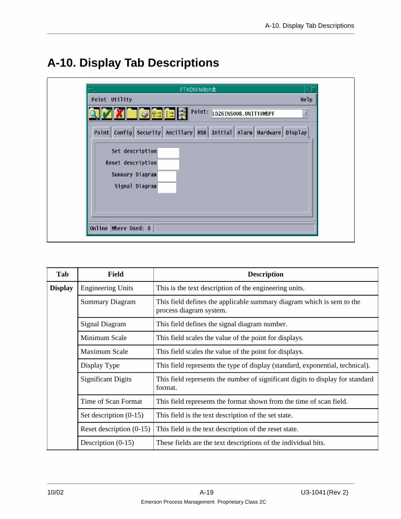
A-10. Display Tab Descriptions
al).
dard
A-10. Display Tab Descriptions
Tab Field Description
Display Engineering Units This is the text description of the engineering units.
Summary Diagram This field defines the applicable summary diagram which is sent to theprocess diagram system.
Signal Diagram This field defines the signal diagram number.
Minimum Scale This field scales the value of the point for displays.
Maximum Scale This field scales the value of the point for displays.
Display Type This field represents the type of display (standard, exponential, technic
Significant Digits This field represents the number of significant digits to display for stanformat.
Time of Scan Format This field represents the format shown from the time of scan field.
Set description (0-15) This field is the text description of the set state.
Reset description (0-15) This field is the text description of the reset state.
Description (0-15) These fields are the text descriptions of the individual bits.
10/02 A-19 U3-1041(Rev 2)Emerson Process Management Proprietary Class 2C

A-11. Byte Params Tab Descriptions
A-11. Byte Params Tab Descriptions
Tab Field Description
Byte Params 1 thru 16 Represents the byte parameters of the algorithm. Only appliesto the algorithms selected in the Config tab. This allows theuser to see what fields apply to the algorithm. Only thealgorithms that need to be tuned will be tuned.
U3-1041 (Rev 2) A-20 10/02Emerson Process Management Proprietary Class 2C

A-12. Instrumentation Tab Description
A-12. Instrumentation Tab Description
10/02 A-21 U3-1041(Rev 2)Emerson Process Management Proprietary Class 2C

A-12. Instrumentation Tab Description
Tab Field Description
Instrumentation Scaling:Bottom output scale
Top output scale
Sensor:Low sensor limit
High sensor limit
Low sensor deadbandrange
High sensor deadbandrangeLow operating range
High operating range
This field is used to linearly convert the value to the cardoutput level.This field is used to linearly convert the value to the cardoutput level.
This field indicates the low limit of the signal’s operatingrange.
This field indicates the high limit of the signal’s operatingrange.
This field maps to the BL field of the point record.
This field maps to the BH field of the point record.
This field performs conversion coefficient calculation andchecking.
This field performs conversion coefficient calculation andchecking.
U3-1041 (Rev 2) A-22 10/02Emerson Process Management Proprietary Class 2C

A-12. Instrumentation Tab Description
Instrumentation(Cont’d)
Conversion:Field transmitter type
B or TB=70% Platinum + 30%Rhodium or94% Platinum + 6%Rhodium
E or TE = Chromel/Constantan
J or TJ = Iron/Constantan
K or TK = Chromel/Alumel
R or TR = Platinum +13% Rhodium
S or TS = Platinum +10% Rhodium
T or TT = Copper/Constantan
Thermocoupletemperature units
Conversion Type
This field identifies the field transmitter type for use instandard thermocouple conversions. If this field is specified,and the individual conversion coefficient fields are notspecified, the conversion coefficient fields will beautomatically assigned based on the thermocouple_units. Theconversion type is set to the P5 field. If this field is notspecified, the conversion type must be specified individually.
This field identifies the temperature units (Fahrenheit orCelsius) used for conversion coefficient calculation based onknown field transmitter types.
This field identifies the type of equation(0-5) to be used for conversion to engineering units. (SeeNote)
Tab Field Description
10/02 A-23 U3-1041(Rev 2)Emerson Process Management Proprietary Class 2C

A-12. Instrumentation Tab Description
Instrumentation(Cont’d)
ConversionCoefficient 1 - 6
Cold JunctionCompensation:CJ Compensationname
CJC temperature units
CJC conversioncoefficient 1-2
These values are specified in units of volts. If the field_transmitter_ type and thermocouple_units fields arespecified, these conversion coefficient fields are assignedautomatically based on a table lookup. Otherwise, the fieldscan be specified individually.
This field identifies the cold-junction compensation to beperformed for the point.
This field is used for cold-junction compensation conversion.
These fields map directly to fields 7V and 8V of the pointrecord and are used for cold junction compensation.
Note
0 - Y = X- Linear1 - Y = {1V}X + {2V} - Linear2 - Y = {1V} + {2V}X + {3V}X2 + {4V}X3 +{5V}X4 + {6V}X5 Fifth OrderPolynomial3 - Y = {1V} [SQRT (X + {2V})] + {3V}Square Root4 - Y = {1V}[EXP ({2V}X)] + {3V}Exponential5 - Y = SQRT (Fifth Order Polynomial Y, as defined for Entry 2) SQRT of Fifth OrderPolynomial
The variables used in the equations are defined as follows:
X = Original input value, which is converted to Y (engineering units) by the specifiedtype of conversion.Y = Final, converted value of the analog input.C1 - C6 = Conversion coefficients.
Tab Field Description
U3-1041 (Rev 2) A-24 10/02Emerson Process Management Proprietary Class 2C

A-13. Int Params Tab Descriptions
lyusereed
A-13. Int Params Tab Descriptions
Tab Field Description
Int Params 1 thru 60 Represents the integer parameters of an LC (algorithm) record. Onapplies to the algorithms selected in the Config tab. This allows theto see what fields apply to the algorithm. Only the algorithms that nto be tuned will be tuned.
10/02 A-25 U3-1041(Rev 2)Emerson Process Management Proprietary Class 2C

A-14. Real Param Tab Descriptions
ly
A-14. Real Param Tab Descriptions
Tab Field Description
Real Params Up to 30 Represents the real parameters of an LC (algorithm). Onlyapplies to the algorithms selected in the Config tab. Thisallows the user to see what fields apply to the algorithm. Onthe algorithms that need to be tuned will be tuned.
U3-1041 (Rev 2) A-26 10/02Emerson Process Management Proprietary Class 2C

A-15. Plant Mode Tab Description
d inntlant
A-15. Plant Mode Tab Description
Tab Field Description
Plant Modes(1 to 6)
Plant Mode (1-6):Auto resetAuto acknowledgeAlarm priorityAlarm cutout nameAlarm cutout delay timeAlarm cutout bitAlarm group maskAlarm group bit senseHigh alarm limit 1- 4High alarm limit incrementalHigh alarm priority 1 -4High reasonability limitLow alarm limit incrementalLow alarm priority 1 - 4Low reasonability limit
These fields are the same as the ones previously describethe Alarm, Config, and Limit tabs in this appendix. If PlaModes are used, then each one must be defined for each PMode (1-6) used in the system.
10/02 A-27 U3-1041(Rev 2)Emerson Process Management Proprietary Class 2C
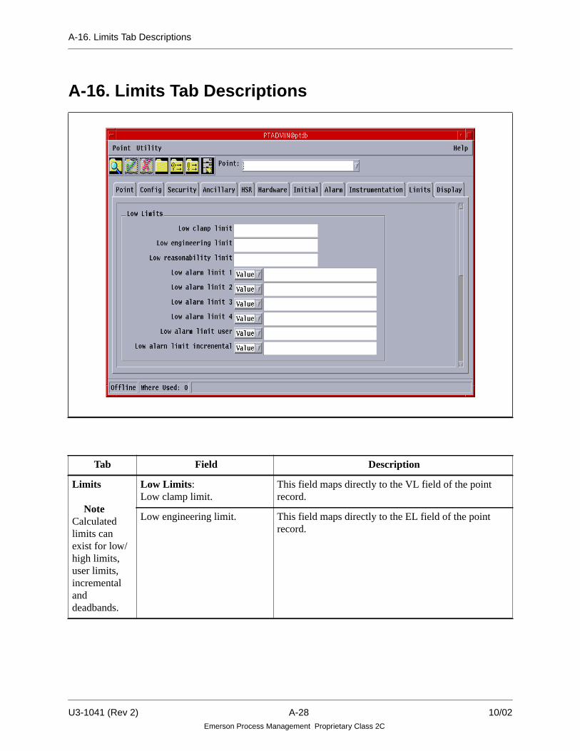
A-16. Limits Tab Descriptions
A-16. Limits Tab Descriptions
Tab Field Description
Limits
NoteCalculatedlimits canexist for low/high limits,user limits,incrementalanddeadbands.
Low Limits:Low clamp limit.
This field maps directly to the VL field of the pointrecord.
Low engineering limit. This field maps directly to the EL field of the pointrecord.
U3-1041 (Rev 2) A-28 10/02Emerson Process Management Proprietary Class 2C

A-16. Limits Tab Descriptions
Limits(Cont’d)
Low reasonability limit. These fields map directly to the RW field of the pointrecord.
Analog points can have a high/low Engineering Rangelimit and a high/low Reasonability limit. These limitscan be defined as a value only.
Engineering Range limits and the Reasonability limitsdo not generate alarms. When a point exceeds theEngineering Range limit, the point Quality is set (P)oor.When a point exceeds the Reasonability limit, theQuality is set (B)ad. The high/low deadbands definedfor the high/low deadbands defined for the high/lowalarm limits described above also apply to these limits.
Low alarm limit 1 - 4. These fields map directly to the LL, ZL, 3Z, and 4Z ofthe point record.
Low alarm limit incremental. This field maps directly to the ZM field of the pointrecord.
Analog points can have up to 4 different high alarmlimits and 4 different low alarm limits. The limits mayeither be a Value or the name of another analog point inthe system (called a variable alarm).
Alarms are processed from limit 4 down to limit 1. Thelimits should increase in value for High limits 1 to 4, anddecrease in value for Low limits 1 to 4 (for example, ifHigh Limit = 100.0, High Limit 2 should be of greatervalue).
An alarm priority can be assigned to each of the 4 highand each of the 4 low alarm limits to differentiate thecritically of the alarm situation.
One High and One Low deadband can be defined toprevent the point from toggling in and out of alarm.
One High and one Low incremental limit may bedefined. The incremental limits take effect when thevalue of the point passes the LAST defined alarm limit.
Alarm fields do not apply to record type SA.
Tab Field Description
10/02 A-29 U3-1041(Rev 2)Emerson Process Management Proprietary Class 2C

A-16. Limits Tab Descriptions
Limits(Cont’d)
Low alarm limit user. This field maps directly to the UL field of the pointrecord.
Analog points can have 2 user defined alarms; one highand one low. The limits may be either a Value or thename of another analog point in the system. Thesealarms are independent of the 4 high and 4 low alarms.The high/low deadbands defined for the 4 high/lowalarms apply to these user limits also. Exceeding thesealarms will generate an alarm message.
A separate alarm priority can be defined for the high andlow user defined alarms.
High Limits:High clamp limit.
This field maps directly to the VH field of the pointrecord.
High engineering limit. This field maps directly to EH field of the point record.
High reasonability limit. This field maps directly to the RV field of the pointrecord.Analog points can have a high/low Engineering Rangelimit and a high/low Reasonability limit. These limitscan be defined as a value only.
Engineering Range limits and the Reasonability limitsdo not generate alarms. When a point exceeds theEngineering Range limit, the point Quality is set (P)oor.When a point exceeds the Reasonability limit, theQuality is set (B)ad. The high/low deadbands definedfor the high/low deadbands defined for the high/lowalarm limits described above also apply to these limits.
High alarm limit 1 -4. These fields map directly to the HL, ZH, 3Y, and 4Yfields of the point record.
Tab Field Description
U3-1041 (Rev 2) A-30 10/02Emerson Process Management Proprietary Class 2C

A-16. Limits Tab Descriptions
Limits(Cont’d)
High alarm limit incremental. This field maps directly to the ZI field of the pointrecord.
Analog points can have up to 4 different high alarmlimits and 4 different low alarm limits. The limits maybe either a Value or the name of another analog point inthe system (called a variable alarm).
Alarms are processed from limit 4 down to limit 1. Thefirst limit found causes an alarm message. The limitsshould increase in value for High limits 1 to 4 (forexample, if High Limit 1 = 100.0, High Limit 2 shouldbe of greater value). Exceeding an alarm limit willgenerate an alarm message.
An alarm priority can be assigned to each of the 4 highand each of the 4 low alarm limits to differentiate thecritically of the alarm situation.
One High and one Low deadband can be defined toprevent the point from toggling in and out of alarmsituation.
One High and one Low incremental limit may bedefined. The incremental limits take effect when thevalue of the point passes the LAST defined alarm limit.
Alarm fields do not apply to record type SA.
This field maps directly to the UH field of the pointrecord.
Tab Field Description
10/02 A-31 U3-1041(Rev 2)Emerson Process Management Proprietary Class 2C

A-16. Limits Tab Descriptions
Limits(Cont’d)
High alarm limit user. Analog points can have 2 user defined alarms: 1 highand 1 low. The limits may be either a Value or the nameof another valid analog point in the system. Thesealarms are independent of the 4 high and 4 low alarms.The high/low deadbands defined for the 4 high/lowalarms apply to these user limits also. Exceeding thesealarms will generate an alarm message.
A separate alarm priority can be defined for the high andlow user defined alarms.
Deadbands:Low alarm deadband.
High alarm deadband.
This field maps directly to the DJ field of the pointrecord.
This field maps directly to the DB field of the pointrecord.
Tab Field Description
U3-1041 (Rev 2) A-32 10/02Emerson Process Management Proprietary Class 2C

Appendix B. Examples of Creating Points
B-1. Section Overview
This appendix provides examples of creating points using the Point Builder.
Information on tabs and folders may vary per record type. Appendix A containsdescriptions of all the possible point tab fields.
Before creating a point, refer to “Ovation I/O Builder User Guide” (U3-1044) forthe correct hardware set up.
B-1.1. Using the Search Window
Using the Search window will be helpful when creating any type of point. You canchoose an already existing point similar to the point you are creating, then changethe applicable fields to create a new point.
10/02 B-1 U3-1041 (Rev 2)Emerson Process Management Proprietary Class 2C

B-2. Creating Analog Input Points
B-2. Creating Analog Input Points
Tab Required Fields
Point Enter the Point Name.Enter Originating Drop (must be defined to create every point).
Config Accept or change the defaults and go to the next tab.
Security Accept or change the defaults and go to the next tab. A point must be assigned to atleast one security group if standard operator station functions are to be performed(for example, scan on/off, alarm acknowledge, etc).
Ancillary Accept or change the defaults and go to the next tab. (This tab is an optional tab).
HSR Accept or change the defaults and go to the next tab.
Hardware Enter I/O type (must be defined if used as a hardware point).Enter I/O module (must be Analog Input if used as a hardware point).Enter I/O channel (must be defined if used as a hardware point).Enter I/O task index (must be defined if used as a hardware point).For third -party I/O, only I/O type, I/O module, and I/O task index are required.
Initial Accept or change the defaults and go to the next tab.
Alarm Accept or change the defaults and go to the next tab.
Instrumentation Conversion type.Conversion coefficient 1-6.
Limits Accept or change the defaults and go to the next tab.
Display Accept or change the defaults and go to the next tab.
U3-1041 (Rev 2) B-2 10/02Emerson Process Management Proprietary Class 2C
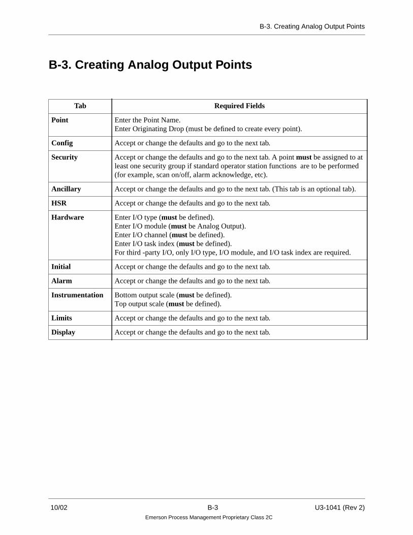
B-3. Creating Analog Output Points
B-3. Creating Analog Output Points
Tab Required Fields
Point Enter the Point Name.Enter Originating Drop (must be defined to create every point).
Config Accept or change the defaults and go to the next tab.
Security Accept or change the defaults and go to the next tab. A point must be assigned to atleast one security group if standard operator station functions are to be performed(for example, scan on/off, alarm acknowledge, etc).
Ancillary Accept or change the defaults and go to the next tab. (This tab is an optional tab).
HSR Accept or change the defaults and go to the next tab.
Hardware Enter I/O type (must be defined).Enter I/O module (must be Analog Output).Enter I/O channel (must be defined).Enter I/O task index (must be defined).For third -party I/O, only I/O type, I/O module, and I/O task index are required.
Initial Accept or change the defaults and go to the next tab.
Alarm Accept or change the defaults and go to the next tab.
Instrumentation Bottom output scale (must be defined).Top output scale (must be defined).
Limits Accept or change the defaults and go to the next tab.
Display Accept or change the defaults and go to the next tab.
10/02 B-3 U3-1041 (Rev 2)Emerson Process Management Proprietary Class 2C

B-4. Creating Digital Input Points
B-4. Creating Digital Input Points
Tab Required Fields
Point Enter the Point Name.Enter Originating Drop (must be defined to create every point).
Config Accept or change the defaults and go to the next tab.
Security Accept or change the defaults and go to the next tab. A point must be assigned to atleast one security group if standard operator station functions are to be performed(for example, scan on/off, alarm acknowledge, etc).
Ancillary Accept or change the defaults and go to the next tab. (This tab is an optional tab).
HSR Accept or change the defaults and go to the next tab.
Hardware Enter I/O type (must be defined).Enter I/O module (must be Digital Input).Enter I/O channel (must be defined).Enter I/O task index (must be defined).
Initial Accept or change the defaults and go to the next tab.
Alarm Accept or change the defaults and go to the next tab.
Display Accept or change the defaults and go to the next tab.
U3-1041 (Rev 2) B-4 10/02Emerson Process Management Proprietary Class 2C

B-5. Creating Digital Output Point
B-5. Creating Digital Output Point
Tab Required Fields
Point Enter the Point Name.Enter Originating Drop (must be defined to create every point).
Config Accept or change the defaults and go to the next tab.
Security Accept or change the defaults and go to the next tab. A point must be assigned to atleast one security group if standard operator station functions are to be performed(for example, scan on/off, alarm acknowledge, etc).
Ancillary Accept or change the defaults and go to the next tab. (This tab is an optional tab).
HSR Accept or change the defaults and go to the next tab.
Hardware Enter I/O type (must be defined).Enter I/O module (must be Digital Output).Enter I/O channel (must be defined).Enter I/O task index (must be defined).
Initial Accept or change the defaults and go to the next tab.
Alarm Accept or change the defaults and go to the next tab.
Display Accept or change the defaults and go to the next tab.
10/02 B-5 U3-1041 (Rev 2)Emerson Process Management Proprietary Class 2C

B-6. Creating Packed Digital Points
B-6. Creating Packed Digital Points
Tab Required Fields
Point Enter the Point Name.Enter Originating Drop. (must be defined to create every point).
Security Accept or change the defaults and go to the next tab. A point must be assigned to atleast one security group if standard operator station functions are to be performed(for example, scan on/off, alarm acknowledge, etc).
Ancillary Accept or change the defaults and go to the next tab. (This tab is an optional tab).
Initial Accept or change the defaults and go to the next tab.
Display Accept or change the defaults and go to the next tab.
U3-1041 (Rev 2) B-6 10/02Emerson Process Management Proprietary Class 2C

B-7. Creating Packed Digital I/O Points
B-7. Creating Packed Digital I/O Points
Tab Required Fields
Point Enter the Point Name.Enter Originating Drop. (must be defined to create every point).
Security Accept or change the defaults and go to the next tab. A point must be assigned to atleast one security group if standard operator station functions are to be performed(for example, scan on/off, alarm acknowledge, etc).
Ancillary Accept or change the defaults and go to the next tab. (This tab is an optional tab).
Initial Accept or change the defaults and go to the next tab.
Display Accept or change the defaults and go to the next tab.
Hardware Register Map Mode.When enabled, permits all 16 bits to be assigned using one I/Olocation and I/O Access path . Disabled means each bit must be separately assigned.(Not used for GE Mark V/VI points.)
10/02 B-7 U3-1041 (Rev 2)Emerson Process Management Proprietary Class 2C

B-8. Creating Algorithm Points
B-8. Creating Algorithm Points
Tab Required Fields
Point Enter the Point Name.Enter Originating Drop. (must be defined to create every point).
Config Accept or change the defaults and go to the next tab.
Security Accept or change the defaults and go to the next tab. A point must be assigned to atleast one security group if standard operator station functions are to be performed(for example, scan on/off, alarm acknowledge, etc).
Ancillary Accept or change the defaults and go to the next tab. (This tab is an optional tab).
Byte Params Accept or change the defaults and go to the next tab.
Int Params Accept or change the defaults and go to the next tab.
Real Params Accept or change the defaults and go to the next tab.
U3-1041 (Rev 2) B-8 10/02Emerson Process Management Proprietary Class 2C
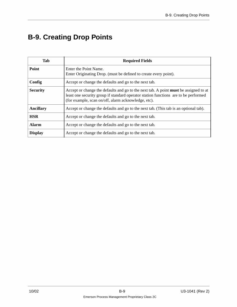
B-9. Creating Drop Points
B-9. Creating Drop Points
Tab Required Fields
Point Enter the Point Name.Enter Originating Drop. (must be defined to create every point).
Config Accept or change the defaults and go to the next tab.
Security Accept or change the defaults and go to the next tab. A point must be assigned to atleast one security group if standard operator station functions are to be performed(for example, scan on/off, alarm acknowledge, etc).
Ancillary Accept or change the defaults and go to the next tab. (This tab is an optional tab).
HSR Accept or change the defaults and go to the next tab.
Alarm Accept or change the defaults and go to the next tab.
Display Accept or change the defaults and go to the next tab.
10/02 B-9 U3-1041 (Rev 2)Emerson Process Management Proprietary Class 2C

B-10. Creating Module Points
B-10. Creating Module Points
Tab Required Fields
Point Enter the Point Name.Enter Originating Drop. (must be defined to create every point).
Config Accept or change the defaults and go to the next tab.
Security Accept or change the defaults and go to the next tab. A point must be assigned to atleast one security group if standard operator station functions are to be performed(for example, scan on/off, alarm acknowledge, etc).
HSR Accept or change the defaults and go to the next tab.
Alarm Accept or change the defaults and go to the next tab.
Hardware Accept or change the defaults and go to the next tab.
Display Accept or change the defaults and go to the next tab.
NoteWhen creating Module Points, I/O Modules must be configured correctly through the I/O builder forcorrect operation on the system.
U3-1041 (Rev 2) B-10 10/02Emerson Process Management Proprietary Class 2C

B-11. Creating Node Points
B-11. Creating Node Points
Tab Required Fields
Point Enter the Point Name.Enter Originating Drop. (must be defined to create every point).
Config Accept or change the defaults and go to the next tab.
Security Accept or change the defaults and go to the next tab. A point must be assigned to atleast one security group if standard operator station functions are to be performed(for example, scan on/off, alarm acknowledge, etc).
HSR Accept or change the defaults and go to the next tab.
Alarm Accept or change the defaults and go to the next tab.
Hardware Accept or change the defaults and go to the next tab.
Display Accept or change the defaults and go to the next tab.
NoteWhen creating Node Points, I/O Modules must be configured correctly through the I/O builder for correctoperation on the system.
10/02 B-11 U3-1041 (Rev 2)Emerson Process Management Proprietary Class 2C

B-12. Creating Analog/Thermocouple Points
B-12. Creating Analog/Thermocouple Points
Tab Required Fields
Point Enter the Point Name.Enter Originating Drop (must be defined to create every point).
Config Accept or change the defaults and go to the next tab.
Security Accept or change the defaults and go to the next tab. A point must be assigned to atleast one security group if standard operator station functions are to be performed(for example, scan on/off, alarm acknowledge, etc).
Ancillary Accept or change the defaults and go to the next tab. (This tab is an optional tab).
HSR Accept or change the defaults and go to the next tab.
Hardware Enter I/O type (must be defined).
Enter I/O module (Must be a module capable of supporting Thermocouple inputs.Typically, such an I/O module will be described with “...w/temperature sensor” orwith “...w/OTD” (Open Thermocouple Detection)).
Enter I/O channel (must be defined).
Enter I/O task index (must be defined).
Initial Accept or change the defaults and go to the next tab.
Alarm Accept or change the defaults and go to the next tab.
Instrumentation Enter All Conversion fields (must be defined).
Enter CJ compensation name (must be defined).
Enter CJC conversion coefficient (must be defined to create a thermocouple point).(Coefficients are discussed in R3-1150).
Limits Accept or change the defaults and go to the next tab.
Display Accept or change the defaults and go to the next tab.
Note
A ninth channel is provided when using the Analog Input module with temperature sensor. This ninth pointis needed for the CJ Compensation field of the Point Builder Instrumentation Tab when defining the eightother thermocouple points for the AI module.
U3-1041 (Rev 2) B-12 10/02Emerson Process Management Proprietary Class 2C
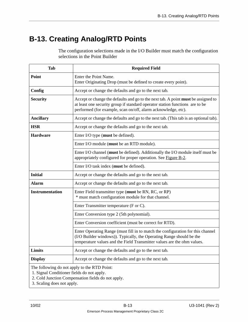
B-13. Creating Analog/RTD Points
B-13. Creating Analog/RTD Points
The configuration selections made in the I/O Builder must match the configurationselections in the Point Builder
Tab Required Field
Point Enter the Point Name.Enter Originating Drop (must be defined to create every point).
Config Accept or change the defaults and go to the next tab.
Security Accept or change the defaults and go to the next tab. A point must be assigned toat least one security group if standard operator station functions are to beperformed (for example, scan on/off, alarm acknowledge, etc).
Ancillary Accept or change the defaults and go to the next tab. (This tab is an optional tab).
HSR Accept or change the defaults and go to the next tab.
Hardware Enter I/O type (must be defined).
Enter I/O module (must be an RTD module).
Enter I/O channel (must be defined). Additionally the I/O module itself must beappropriately configured for proper operation. See Figure B-2.
Enter I/O task index (must be defined).
Initial Accept or change the defaults and go to the next tab.
Alarm Accept or change the defaults and go to the next tab.
Instrumentation Enter Field transmitter type (must be RN, RC, or RP) * must match configuration module for that channel.
Enter Transmitter temperature (F or C).
Enter Conversion type 2 (5th polynomial).
Enter Conversion coefficient (must be correct for RTD).
Enter Operating Range (must fill in to match the configuration for this channel(I/O Builder windows)). Typically, the Operating Range should be thetemperature values and the Field Transmitter values are the ohm values.
Limits Accept or change the defaults and go to the next tab.
Display Accept or change the defaults and go to the next tab.
The following do not apply to the RTD Point: 1. Signal Conditioner fields do not apply. 2. Cold Junction Compensation fields do not apply. 3. Scaling does not apply.
10/02 B-13 U3-1041 (Rev 2)Emerson Process Management Proprietary Class 2C

B-13. Creating Analog/RTD Points
The following figures show the channel selections that must be chosen from the I/O Builder to match the configuration module. These windows can be viewed atthe same time as the Instrumentation tab window in the Point Builder (Figure B-3).
Figure B-1. I/O Builder Configuration Tree
Figure B-2. Channel Selection in I/O Builder
U3-1041 (Rev 2) B-14 10/02Emerson Process Management Proprietary Class 2C
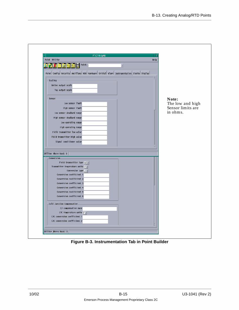
B-13. Creating Analog/RTD Points
Figure B-3. Instrumentation Tab in Point Builder
Note:The low and highSensor limits arein ohms.
10/02 B-15 U3-1041 (Rev 2)Emerson Process Management Proprietary Class 2C

B-14. Creating Pulse Accumulator Points
B-14. Creating Pulse Accumulator Points
Tab Required Fields
Point Enter the Point Name.Enter Originating Drop. (must be defined to create every point).
Config Accept or change the defaults and go to the next tab.
Security Accept or change the defaults and go to the next tab. A point must be assigned to atleast one security group if standard operator station functions are to be performed(for example, scan on/off, alarm acknowledge, etc).
Ancillary Accept or change the defaults and go to the next tab.
HSR Accept or change the defaults and go to the next tab.
Hardware Enter I/O type (must be defined).Enter I/O module (must be a Pulse Accumulator module).Enter I/O channel (must be defined).Enter I/O task index (must be defined).
Initial Accept or change the defaults and go to the next tab.
Alarm Accept or change the defaults and go to the next tab.
Instrumentation Accept or change the defaults and go to the next tab.
Limits Accept or change the defaults and go to the next tab.
Display Accept or change the defaults and go to the next tab.
U3-1041 (Rev 2) B-16 10/02Emerson Process Management Proprietary Class 2C

B-15. Creating HART Analog Input Points
B-15. Creating HART Analog Input Points
Tab Required Fields
Point Enter the Point Name.Enter Originating Drop (must be defined to create every point).
Config Accept or change the defaults and go to the next tab.
Security Accept or change the defaults and go to the next tab. A point must be assigned to atleast one security group if standard operator station functions are to be performed(for example, scan on/off, alarm acknowledge, etc).
Ancillary Accept or change the defaults and go to the next tab.
HSR Accept or change the defaults and go to the next tab.
Hardware Enter I/O type (must be defined).Enter I/O module (must be a HART Analog Input module).Enter I/O channel (must be defined).Enter I/O task index (must be defined).Enter HART Variable (must be defined):
The above I/O Access Path is only available if the HART Module is configured forMultivariable operation, through the I/O Builder.
Initial Accept or change the defaults and go to the next tab.
Alarm Accept or change the defaults and go to the next tab.
Instrumentation Accept or change the defaults and go to the next tab.
Limits Accept or change the defaults and go to the next tab.
Display Accept or change the defaults and go to the next tab.
HART Variable I/O Access Path
4-20mA primary variable (PV) = 0 (or blank)
Primary Digital variable (PV) = 1
Secondary Digital variable (SV) = 2
Tertiary Digital variable (TV) = 3
Fourth Digital variable (QV) = 4
10/02 B-17 U3-1041 (Rev 2)Emerson Process Management Proprietary Class 2C

B-16. Creating HART Analog Output Points
B-16. Creating HART Analog Output Points
Tab Required Fields
Point Enter the Point Name.Enter Originating Drop (must be defined to create every point).
Config Accept or change the defaults and go to the next tab.
Security Accept or change the defaults and go to the next tab. A point must be assigned to atleast one security group if standard operator station functions are to be performed(for example, scan on/off, alarm acknowledge, etc).
Ancillary Accept or change the defaults and go to the next tab.
HSR Accept or change the defaults and go to the next tab.
Hardware Enter I/O type (must be defined).Enter I/O module (must be a HART Analog Output module).Enter I/O channel (must be defined).Enter I/O task index (must be defined).Enter HART Variable (must be defined):
The above I/O Access Path is only available if the HART Module is configured forMultivariable operation, through the I/O Builder.
Initial Accept or change the defaults and go to the next tab.
Alarm Accept or change the defaults and go to the next tab.
Instrumentation Accept or change the defaults and go to the next tab.
Limits Accept or change the defaults and go to the next tab.
Display Accept or change the defaults and go to the next tab.
HART Variable I/O Access Path
4-20mA primary variable (PV) = 0 (or blank)
Primary Digital variable (PV) = 1
Secondary Digital variable (SV) = 2
Tertiary Digital variable (TV) = 3
Fourth Digital variable (QV) = 4
U3-1041 (Rev 2) B-18 10/02Emerson Process Management Proprietary Class 2C

B-17. Guidelines for Creating Third Party Points
B-17. Guidelines for Creating Third Party Points
A third party point is a point that originates from an Ovation Controller and isupdated by a third party driver. (Described in “Ovation Controller User Guide”U3-1032). The current third party drivers are: Allen-Bradley, Modbus, RTP IOBC6700, GE Mark V and GE Mark VI. The purpose of the drivers is to allow theController to access register data from an external device and map the data toprocess points.
Point configuration for third party points is the same as for other types of points,except for the configuration information needed for the Hardware Tab (as seenbelow). Table B-1 describes the fields in the Hardware Tab.
10/02 B-19 U3-1041 (Rev 2)Emerson Process Management Proprietary Class 2C

B-17. Guidelines for Creating Third Party Points
Table B-1. Hardware Tab Fields
Field Description
IO type This is set to “T” to indicate a third party point. This causes the “IO access path”to be enabled.
IO module The third party driver is assigned a device number in the Controller DriverParameters dialog box (described in “Ovation Controller User Guide” (U3-1032). This field is used to match the point with the device number.
It is recommended that devices 1 and 2 be reserved for Q-line and Ovation (R-line) IO since these devices correspond to actual PCI slot numbers.
Since there is typically no hardware associated with a third party driver, it isrecommended that third party drivers be assigned to devices 3, 4, or 5.Otherwise, if a third party driver were assigned to device 1 or 2, then PCI slot 1or 2 could not be used.
IO channel This is disabled for third party points.
IO task index(Control Task)
Points are grouped by the Control task index so that they can be updated(scanned) at different rates. The Control task rate is set by the Admin Tool in theController Configuration Parameters dialog box(described in “Ovation Controller User Guide” (U3-1032).
Control Task 1 = 100 msecControl Task 2 = 1000 msec (1 second)Control Tasks 3, 4, and 5 are user configurable and the scan rate should beappropriate for the application and system needs.
It is recommended that third party points be given their own task area. The scanrate should be no faster than one second because of the communication overhead.
No more than 2000 points can be assigned to a task area.
IO access path A text string which describes the register address must be entered into this field.
Packed points (LP) have 16 I/O Access paths, one for each bit. The bit numbershould be zero (0) in all 16 I/O Access paths. All 16 paths should be identical.The Controller treats each bit as a separate point if the access paths are different.
Termination fields Not applicable for third party points.
Register Map Mode(For Packed Digital I/O points only.)
When enabled, permits all 16 bits to be automatically assigned using one I/Olocation and I/O Access path specification. If disabled (default), then each of the16 bits must be separately assigned with their own I/O location and I/O Accessspecification. (Not used for GE Mark V/VI points.)
U3-1041 (Rev 2) B-20 10/02Emerson Process Management Proprietary Class 2C

B-17. Guidelines for Creating Third Party Points
B-17.1. Creating Points for an Allen-Bradley Driver
The Allen-Bradley driver interfaces to an A-B PLC5 or SLC500 programmablecontroller over a TCP/IP ethernet link.
The following is an example of the format that is used in the IO access path fieldfor an Allen-Bradley third party point:
Note
The Allen-Bradley protocol allows for two styles of addressing when accessing thebinary “B” files. The first style of bit addressing is B3:12/0. This driver uses the firststyle of addressing. The second style of bit addressing is B:3/192 (same as B3:12/0) This driver uses the first style of addressing.
Each File and Register number need to be specified as digital or octal. A leading 0indicates an octal number. Example, I:0115/017 is the same as I:77/15.
Table B-2. Example and Definition of I/O Access Path for Allen-Bradley
Example: AB PLC5 2 IN FFYYY:NNN/BBB SIGNED
AB PLC5 Identifies the third party driver type.
2 Hostname index.The driver will communicate with hostname “plc5-2” which is configured by the OvationAdmin Tool in the Allen-Bradley Driver Configuration dialog box (described in“Ovation Controller User Guide” (U3-1032).
IN orOUT
Indicates whether the PLC value is read into the process point or if the process point valueis written out to the PLC.
FF Allen-Bradley file type. Choices are: O, I, N, F, S
YYY File Number: (0 - 1023)
NNN Register Number (0 -1023)Register numbers that begin with a zero (0) are interpreted as octal numbers. AddressN7:020 is equivalent to N7:16. (See note)
BBB Bit Number (0 - 15)
SIGNED Optional keyword that causes the AB Register to be interrupted as a Signed integer.The default is Unsigned.
10/02 B-21 U3-1041 (Rev 2)Emerson Process Management Proprietary Class 2C

B-17. Guidelines for Creating Third Party Points
Additional Examples
• AB PLC5 3 IN F8:20 = Read a floating point value F8:20 from a SLC500with hostname plc5-3.
• AB PLC5 1 OUT N7:20 = Write the point value to 16 bit register N7:10at plc5-1.
• AB PLC5 2 IN I:014/12 = Read digital input register I:014 bit 12 fromplc5-2 into a digital point.
Analog Input Cards
The Ovation controller Allen-Bradley PLC5 driver maps process points to PLC5registers via an ethernet link. Normally, if the PLC register value was successfullyread or written, then the point quality is set to GOOD.
An additional feature allows the process point quality to reflect the status of theAllen-Bradley input card, where the register value originated. This means that if arack of analog input cards loses power, then the process points for those inputs goto BAD quality.
To read an analog input card, a PLC5 must contain a Block Transfer Read in itsladder program. This will read the card values and status and write them to aspecified set of N registers.
For example, if an eight channel analog input card is moved to N7:10, then thestructure is:
N7:10 card diagnostic should be all zerosN7:11 underrange bit 0 is for channel 1N7:12 overrange bit 0 is for channel 1N7:13 data polarityN7:14 channel 1 value 12 bit unsigned integer valueN7:15 channel 2 valueN7:16 channel 3 valueN7:17 channel 4 valueN7:18 channel 5 valueN7:19 channel 6 valueN7:20 channel 7 valueN7:21 channel 8 value
U3-1041 (Rev 2) B-22 10/02Emerson Process Management Proprietary Class 2C

B-17. Guidelines for Creating Third Party Points
To read the value of the channel 4 into a analog process point, the IO_ACCESSstring would be “AB PLC5 1 N7:17/4”. A bit number specified for an analog pointis interpreted as a channel number. The controller treats this as a QLINE analoginput. The polarity register (N7:13) is used to determine the sign of the value. Thequality is set to BAD if the card diagnostic (N7:10) is non-zero, or if the underrangeor overrange bit is set.
Note that the driver expects the card diagnostic register values to be returned in thesame message as the channel value. For this reason, it may be necessary to read thecard diagnostic (N7:10) register into a dummy point to cause the driver to access theentire array.
Digital Input Cards
Discrete input values from digital input cards appear in the input (I) file. The I/Orack address is determined from the register address. For example, I:014/12 is theinput from rack 01 group 4 bit 12. The status of racks is found in the status file S:7.The status of rack 2 is in S:7 bit 2.
The Allen-Bradley PLC5 driver monitors the addresses it is asked to read. If it readsregister S:7, then it saves the value. The driver sets the quality of a digital processpoint mapped to an input (I) bit based on the value from the S:7 register, if available.
Note that it is necessary to read S:7 into a dummy point to allow its use for pointquality.
10/02 B-23 U3-1041 (Rev 2)Emerson Process Management Proprietary Class 2C

B-17. Guidelines for Creating Third Party Points
B-17.2. Creating Points for a Modbus Driver
The Modbus driver will interface to a Modbus slave device over a TCP/IP ethernetlink or a serial RS232 link.
The following is an example of the format that is used in the IO access path fieldfor a Modbus third party point:
Additional Examples
• MODBUS 2 OUT 10 PLC_3 = Set discrete coil number 10 (address 9) atplc_3. Slave addresses are usually ignored by TCP/IP devices.
• MODBUS 4 IN 30008 PLC_1 SHORT = Read input register 30008(address 7) at plc_1 as a signed short.
• MODBUS 1 IN 40001 FLOAT PLC_1 = Read holding registers 40001and 40002 as a float from plc_1.
Table B-3. Example and Definition of I/O Access Path for Modbus
Example: MODBUS 3 IN NNNNN SHORT PLC_4
MODBUS Identifies a Modbus driver point.
3 Modbus slave address.
IN orOUT
Indicates whether the Modbus slave value is read into a process point or written from apoint.
NNNNN Modbus coil or register number:Number Address1 - 9999 Discrete Coils 0 - 999810001 - 19999 Input Coils 0 - 999830001 - 39999 Input Registers 0 - 999840001 - 49999 Holding Registers 0 - 9998
SHORT Keyword that determines how a register value is interpreted (optional and not orderdependent). Choices are:SHORT, USHORT, LONG, ULONG, and FLOATDefault = USHORTKeywords SB and SW allow register byte order to be changed.Floating point values are stored in two contiguous 16 bit registers.
PLC_4 Identifies the slave hostname for TCP/IP communication (optional and not orderdependent).The hostnames are configured by the Ovation Admin Tool in the Modbus DriverConfiguration dialog box (described in “Ovation Controller User Guide” U3-1032).
U3-1041 (Rev 2) B-24 10/02Emerson Process Management Proprietary Class 2C

B-17. Guidelines for Creating Third Party Points
B-17.3. Creating Points for an RTP IOBC Driver (Real Time Products)
The IOBC driver will interface to a Real Time Products RTP IOBC 6700 over aTCP/IP ethernet link. The messages that the driver sends to the IOBC contain acommand word. The information entered in the IO access path field is used toencode this command word, and the command word for each type of RTP IO isdifferent. Therefore, RTP IO card documentation is required in order to configurethis field.
The following is an example of the format that is used in the IO access path fieldfor an RTP IOBC third party point:
Table B-4. Example and Definition of I/O Access Path for RTP
Example: IOBC 1 AOUT 3 4 6 0 2 AUTOCAL
IOBC Identifies an RTP IOBC driver point.
1 Identifies the hostname index (iobc_1).The hostname is configured by the Ovation Admin Tool in the RTP IOBC DriverConfiguration dialog box (described in “Ovation Controller User Guide” U3-1032).
AOUT RTP IO card type keyword. (For other keywords, see Table B-5)
3 Device address of RTP card cage.
4 Slot number for digital cards, AD converter address.
6 Bit number of digital card or gate slot address of analog card.
0 Analog channel number.
2 Gain code.
AUTOCAL Optional keywords for the IOBC command word.Other commands: AUTOCAL SIGDIF ODD OPEN
Table B-5. Keyword Options
AIN Analog Input DOUT Digital Output
AINU Analog Input Unsigned DOUTU Digital Output Unsigned
AOUT Analog Output AWRIN Wide Range Analog Input
AOUTU Analog Output Unsigned DPTIN Digital Pulse Train Input
DIN Digital Input APTOUT Analog Pulse Train Output
DINU Digital Input Unsigned
10/02 B-25 U3-1041 (Rev 2)Emerson Process Management Proprietary Class 2C

B-17. Guidelines for Creating Third Party Points
B-17.4. Creating Points for a General Electric Mark V Driver
Before creating third party points, the Controller’s PCI will need to be configuredwith the GE Mark V. This is done by using the I/O builder. Refer to “Ovation I/OBuilder User Guide”(U3-1044) for more instructions on configuring the I/O.
The following is an example of the format that is used in the IO access path fieldfor a GE Mark V third party point:
Table B-6. Example and Definition of I/O Access Path for GE Mark V
Example: L41BKRC_CPB PUSHBUTTON GA 1
L41BKRC_CPB GE Point Name.
PUSHBUTTON Point Type. Valid Types are ALARM, EVENT, SWEVENT, SETPOINTPERIODIC, PUSHBUTTON (see Table B-7).
GA GE Mark V.
1 <G>node Number from the Admin Tool.1
OR
Example DWATT PERIODIC GA 1 S
DWATT GE Point Name.
PERIODIC Point Type. Valid Types are ALARM, EVENT, SWEVENT, SETPOINTPERIODIC, PUSHBUTTON (see Table B-7).
GA GE Mark V.
1 <G>node Number from the Admin Tool.1
S Used for analog periodic point as a (S)igned or (U)nsigned value(Default is Signed).
1 Each Ovation Controller can support up to four unique nodes. The <G>nodes are associated with acontrol task. The time period of any periodic points on the associated <G>node will be the same periodas the control task associated with the <G>node. The time period should be no faster than one second.
Table B-7. Valid Ovation Record Types
Point Type Record Type Notes:
ALARM Digital Point (LD, DD) Records Default point is not SOE. To define the pointas an SOE point, select the SOE box under theConfig tab on the Point Builder.
U3-1041 (Rev 2) B-26 10/02Emerson Process Management Proprietary Class 2C

B-17. Guidelines for Creating Third Party Points
EVENT Digital Point (LD, DD) Records. Default point is not SOE. To define the pointas an SOE point, select the SOE box under theConfig tab on the Point Builder.
SWEVENT Digital Point (LD, DD) Records. Mark V only.
PUSHBUTTON Digital Point (LD, DD) Records. For both Mark V and Mark VI, the digital val-
ues must be true for at least two seconds to
ensure being sent to GE.
SETPOINT Analog Point (LA, DA) Records. For Gain and Bias on the Analog points, usethe Conversion Coefficients (under the Instru-mentation tab) to assign the information to thepoint.
PERIODIC Analog (LA, DA) andDigital (LD, DD) Records.
For Gain and Bias on the Analog points, usethe Conversion Coefficients (under the Instru-mentation tab) to assign the information to thepoint.
For Analog points, the incoming value can beinterpreted as either signed two’s complementvalues or unsigned values. If the sign is notassigned, then the default is signed.
Table B-7. Valid Ovation Record Types (Cont’d)
Point Type Record Type Notes:
10/02 B-27 U3-1041 (Rev 2)Emerson Process Management Proprietary Class 2C

B-17. Guidelines for Creating Third Party Points
B-17.5. Creating Points for a General Electric Mark VI Driver
The following is an example of the format used in the IO access path field for a GEMark VI third party point:
The High and Low Sensor Limits do not apply in this application.
For all Periodic Analog Points, the High Sensor Limit must be greater than 65536. The Low
Sensor Limit must be than less than -32769.
For 32-bit floating points, the high and low sensor limits must be outside the normal operating
engineering units.
For example, if the normal operating engineering unit range for a point is 0 through 500 psi, the
high sensor limit must be greater than 500 and the low sensor limit must be less than 0.
These limits are set under the Instrumentation tab in the Point Builder.
Table B-8. Example and Definition of I/O Access Path for GE Mark VI
Example: L41BKRC_CPB PUSHBUTTON GA 1
L41BKRC_CPB GE Point Name.
PUSHBUTTON Point Type. Valid Types are ALARM, EVENT, SWEVENT, SETPOINTPERIODIC, PUSHBUTTON (see Table B-10).
GA GE Mark VI controller name.
1 <G>node HMI Number from the Admin Tool.
OR
Example DWATT PERIODIC GA 1 SINT
DWATT GE Point Name.
PERIODIC Point Type. Valid Types are: ALARM, EVENT, SWEVENT, SETPOINTPERIODIC, PUSHBUTTON (see Table B-10).
GA GE Mark VI controller name.
1 <G>node HMI Number from the Admin Tool.
SINT Data types are listed below:
USINT Unsigned 8 bit integer UDINT Unsigned 32 bit integer
SINT Signed 32 bit integer DINT Signed 32 bit integer
INT Signed 8 bit integer REAL 32 bit floating pointUINT Unsigned 16 bit integ BOOL Digital
Needed for Periodic and Setpoint types only.
U3-1041 (Rev 2) B-28 10/02Emerson Process Management Proprietary Class 2C

B-17. Guidelines for Creating Third Party Points
Table B-9. Valid Ovation Record Types
Point Type Record Type Notes:
ALARM Digital Point (LD, DD) Records. Default point is not SOE. To define the point
as an SOE point, select the SOE box under the
Config tab on the Point Builder.
EVENT Digital Point (LD, DD) Records. Default point is not SOE. To define the point
as an SOE point, select the SOE box under the
Config tab on the Point Builder.
SWEVENT Digital Point (LD, DD) Records. Mark V only.
PUSHBUTTON Digital Point (LD, DD) Records. For both Mark V and Mark VI, the digital val-
ues must be true for at least two seconds to
ensure being sent to GE.
SETPOINT Analog Point (LA, DA) Records. For scaling of setpoints, use Top Output Scale
and Bottom Output Scale for INT and UINT.
For other data types (USINT, SINT, UDINT,
DINT, REAL), scaling is always one to one.
PERIODIC Analog (LA, DA) and Digital (LD,
DD) Records.
For Gain and Bias on the Analog points, use
the Conversion Coefficients (under the Instru-
mentation tab) to assign the information to the
point.
For all Mark V Analog points, the incoming
value can be interpreted as either signed two’s
complement values or unsigned values. If not
signified, then the default is signed.
10/02 B-29 U3-1041 (Rev 2)Emerson Process Management Proprietary Class 2C


Index
AAccessing the Point Builder 2-1Accessing the Point Group Builder 2-4, 4-1Adding a PDS Group 4-22Adding an HSR Point Group 4-19Adding or Modifying a Point 3-31Admin Tool 1-3Alarm Tab Descriptions A-13Algorithm Point B-8Algorithm Points 3-16Allen-Bradley Driver B-21Analog Input Point B-2Analog Output Point B-3Ancillary Tab Descriptions A-7
BBaseline field 4-12Byte Params Tab Descriptions A-1, A-20
CCheck Consistency Window 3-34Checking Consistency 3-34Config Tab Descriptions A-4Consistency Checking 1-4, 2-3, 3-34Continuous Rate Change option 4-9Controller Driver Parameters
Configuration for Drop Number B-20Creating a Point 3-30Creating Analog/Thermocouple Points B-12
DDeleting a Point 2-2, 3-32Deluxe Analog Points 3-15Deluxe Digital Point 3-15Deluxe Packed Points 3-16Digital Input Point B-4Digital Output Point B-5Display Tab Descriptions A-19Drop Points 3-16, B-9
EExamples for Creating Points B-1
FFields
Bit (0-15) A-12Cold Junction Compensation A-24Collection A-8
Conversion A-23Cutout A-14Deadband algorithm A-9Event A-11Initial Conditions A-12Initial status A-12Low Limits A-28New Alarm/Limit Configuration A-5Plant Mode (1-6) A-27Power Check A-5Priorities A-14Scaling A-22Sensor A-22SOE A-5
GGeneral Electric Mark V Driver B-26General Electric Mark VI Driver B-28Generating HSR PIC Files 2-3, 3-32Global Point Group 4-1Grid menu 4-8Guidelines for Creating Third Party Points B-
19
HHardware Mapping 1-4Hardware Tab Description A-15HART Analog Input Point B-17HART Analog Output Point B-18HSR Group Attributes Window 4-21HSR PIC File Generation 1-5HSR Point Group 4-19HSR Tab Descriptions A-8
II/O parameters 1-4I/O Point Hardware Mapping 1-4Icon/Control Bar 3-10Init Tool 1-3Initial Tab Descriptions A-12Instrumentation Tab Descriptions A-21Int Params Tab Descriptions A-25
LLayout menu 4-6LD 3-21Limits Tab Descriptions A-28Live Interval menu 4-5
10/02 Index-1 U3-1041 (Rev 2)Emerson Process Management Proprietary Class 2C

Index
Login/Menu 3-1Long Analog Points 3-15Long Digital Points 3-15Long Packed Points 3-16
MMenu
Layout 4-6Live Interval 4-5
Menu bar 3-8MMI Trend Configuration 4-15Modbus Driver B-24Modifying a Point 2-2, 3-31Modifying or Adding a PDS Point Group 2-5Modifying or Adding a Point Trend Group 2-4Modifying or Adding an HSR Point Group 2-
5, 4-19Module Points 3-17, B-10
NNode Points 3-17, B-11
OOvation Main Menu 3-1
PPacked Digital Points 3-16, B-6Password rules 3-2PDS Point Group 4-22Plant Mode Tab Description A-27Point Builder
accessing 3-1, 4-1Bottom Status Bar 3-11Icon/Control Bar 3-10Main Window 3-6Menu Bar 3-8Valid Ovation record types B-29
Point Builder Features 1-4consistency Checking 1-4I/O Point Hardware Mapping 1-4Point Filtering 1-5Point Referencing 1-5
Point Builder Record TypeDA 3-20DD 3-22DP 3-24DU 3-27LA 3-19
LC 3-26LD 3-21LP 3-23PD 3-25RM 3-28RN 3-29
Point fieldsPulse Accumulator B-16
Point Filtering 1-5Point Group Builder 4-1point name indicator 3-11Point Object Folder
DA Record Type 3-20DD Record Type 3-22DP Record Type 3-24DU Record Type 3-27LA Record Type 3-19LC Record Type 3-26LD Record Type 3-21LP Record Type 3-23PD Record Type 3-25RM Record Type 3-28RN Record Type 3-29
Point Recordsapplications 3-14
Point Referencing 1-5Point Tab Descriptions A-1, A-2Point Trend Group 4-3Point Type Descriptions 3-14Point Types 3-15Power Tools menu 3-5Print information 3-32Printing 2-3, 3-32Processing Type menu 4-17
QQuadrant trend layout 4-8Quadrant trends 4-11Quick Procedures 2-1
Accessing the Point Builder 2-1Accessing the Point Group Builder 2-4Consistency Checking 2-3Deleting a Point 2-2Generating HSR PIC Files 2-3Modifying a Point 2-2Modifying or Adding a PDS Point Group 2-5Modifying or Adding a Point Trend Group 2-
4
U3-1041 (Rev 2) Index-2 10/02Emerson Process Management Proprietary Class 2C

Index
Modifying or Adding an HSR Point Group2-5
Search Window 2-1
RReal Param Tab Descriptions A-26Record Type Folder Tabs 3-18Reference documents 1-8reserved point name characters 1-8RTD Points B-13RTP IOBC Driver B-25
SScale Limits menu 4-13Search Window 2-1, 3-12Security Tab Descriptions A-6Select A Group window 4-10Shading 4-12Source file
characters 1-7source file
point names 1-6Status Bar 3-11
TTabs
Alarm A-14Ancillary A-7Byte Params A-20Config A-4Display A-19HSR A-8, A-9Initial A-12Instrumentation A-22Int Params A-25Plant Mode A-27Point A-2Real Params A-26Security A-6
Text group 4-24Thermocouple Point B-12Third Party Points B-19Trend Groups 4-3trend_defaults_file 4-15
UUtility Menu 3-9
VValid Ovation record types B-29Valid point name characters 1-7Vertical Side-by-Side trend 4-11
WWhere Used Window 3-13windows
DA Record Type Point Object Folder 3-20DD Record Type Point Object Folder 3-22DP Record Type Point Object Folder 3-24DU Record Type Point Object Folder 3-27LA Record Type Point Object Folder 3-19LC Record Type Point Object Folder 3-26LD Record Type Point Object Folder 3-21Level 4 User Functions Menu 3-3LP Record Type Point Object Folder 3-23Point Builder 1-2, 3-6Point Builder Search 3-12Point Builder Where Used 3-13Power Tools Menu 3-5, 4-1RM Record Type Point Object Folder 3-28Tools Menu 3-4WEStation Login 3-2
XXY Plot trend 4-7
10/02 Index-3 U3-1041 (Rev 2)Emerson Process Management Proprietary Class 2C