Outdoor Gas Fireplace Installation & Operating...
20
Outdoor Gas Fireplace Installation & Operating Instructions Models: ODGSR36A, ODGSR42A PLEASE READ THIS MANUAL BEFORE INSTALLING AND USING APPLIANCE. WARNING: If the information in this manual is not followed exactly, a fire or explosion may result causing property damage, personal injury or loss of life. — Do not store or use gasoline or other flammable vapors and liquids in the vicinity of this or any other appliance — WHAT TO DO IF YOU SMELL GAS • Do not try to light any appliance. • Do not touch any electrical switch; do not use any phone in your building. • Immediately call your gas supplier from a neighbor's phone. Follow the gas supplier's instructions. • If you cannot reach your gas supplier, call the fire department. — Installation and service must be performed by a qualified installer, service agency or the gas supplier. WARNING: Improper installation, adjustment, alteration, service or maintenance can cause injury or property damage. Read the installation, operating and maintenance instructions thoroughly before installing or servicing this equipment. INSTALLER/CONSUMER SAFETY INFORMATION INSTALLER: Leave this manual with the appliance. CONSUMER: Retain this manual for future reference. WARNING! For Outdoor Use Only. ODGSR36A/ODGSR42 Outdoor Fireplace Install Instructions • 20007114 Rev. B • 09/17 Installation and service of this applianceshould be performed by
Transcript of Outdoor Gas Fireplace Installation & Operating...
Outdoor Gas FireplaceInstallation & Operating InstructionsModels: ODGSR36A, ODGSR42A
PLEASE READ THIS MANUAL BEFORE INSTALLING AND USING APPLIANCE.WARNING: If the information in this manual is not followed exactly, a fire or explosion may result causing property damage, personal injury or loss of life.— Do not store or use gasoline or other
flammable vapors and liquids in the vicinity of this or any other appliance
— WHAT TO DO IF YOU SMELL GAS• Do not try to light any appliance.• Do not touch any electrical switch; do not
use any phone in your building.• Immediately call your gas supplier from
a neighbor's phone. Follow the gas supplier's instructions.
• If you cannot reach your gas supplier, call the fire department.
— Installation and service must be performed by a qualified installer, service
agency or the gas supplier.WARNING: Improper installation, adjustment, alteration, service or maintenance can cause injury or property damage. Read the installation, operating
and maintenance instructions thoroughly before installing or servicing this equipment.
INSTALLER/CONSUMER SAFETY INFORMATION
7114ODGSRcover11/03
INSTALLER: Leave this manual with the appliance.CONSUMER: Retain this manual for future
reference.
WARNING!For Outdoor Use Only.
ODGSR36A/ODGSR42 Outdoor Fireplace Install Instructions • 20007114 Rev. B • 09/17
Installation and service of this appliance should be performed by

2
ODGSR Series Outdoor Gas Fireplace
ODGSR36A/ODGSR42 Outdoor Fireplace Install Instructions • 20007114 Rev. B • 09/17
Table of ContentsThank you and Congratulations on your purchase of a Outdoor Lifestyles fireplace.
PLEASE READ THE INSTALLATION & OPERATING INSTRUCTIONS BEFORE USING THE APPLIANCEIMPORTANT: Read all instructions and warnings carefully before starting installation. Failure to follow these
instructions may result in a possible fire hazard and will void the warranty.Installation & Operating Instructions ..........................................................................................3 General Information .............................................................................................................3 Fireplace Dimensions ..........................................................................................................4 Moisture Resistance ............................................................................................................5 Screened Porch Installation ................................................................................................5 Clearance to Combustibles .................................................................................................5 Mantels ...............................................................................................................................5 Hearth ...............................................................................................................................5 Moisture Resistance ............................................................................................................6 Framing & Finishing ............................................................................................................6 Final Finishing .....................................................................................................................6 GasSpecifications ...............................................................................................................7 Gas Inlet & Manifold Pressures ...........................................................................................7 High Elevations ...................................................................................................................7 Valve Access .......................................................................................................................7 Exterior Chase Installation ..................................................................................................8 Gas Line Installation ............................................................................................................8 Remote Wall Switch ............................................................................................................9Operating Instructions Log Installation ..................................................................................................................10 First Firing .........................................................................................................................10 Flame Adjustment .............................................................................................................. 11 Flame Characteristics ........................................................................................................ 11 Optional Weather Enclosures ............................................................................................12 Optional Stainless Steel Hood ...........................................................................................12 Lighting & Operating Instructions ......................................................................................13 Troubleshooting .................................................................................................................14Maintenance .................................................................................................................................15Replacement Parts ......................................................................................................................16Accessories ..................................................................................................................................18Warranty .......................................................................................................................................19
Proposition 65 Warning: Fuels used in gas, woodburn-ingoroilfiredappliances,andtheproductsofcombus-tion of such fuels, contain chemicals known to the State of California to cause cancer, birth defects and other reproductive harm.California Health & Safety Code Sec. 25249.6
IMPORTANT:PLEASE READ THE FOLLOWING CAREFULLY
Remove any plastic from trim parts before turning the fireplace“ON”.Itisnormalforfireplacesfabricatedofsteeltogiveoffsome expansion and/or contraction noises during the start up or cool down cycle. Similar noises are found with your furnace heat exchanger or car engine. It is not unusual for your Outdoor Lifestyles Fireplaces gas fireplace to giveoff someodor the first time it isburned. This is due to the curing of the paint and any undetected oil used in the manufacturing process.Itisrecommendedthatyouburnyourfireplaceforatleastten(10)continuoushoursthefirsttimeyouuseit.
3
ODGSR Series Outdoor Gas Fireplace
ODGSR36A/ODGSR42 Outdoor Fireplace Install Instructions • 20007114 Rev. B • 09/17
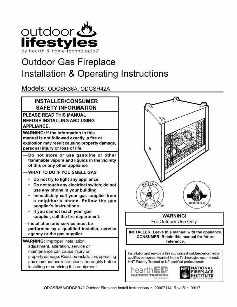
General InformationThisgasapplianceshouldbeinstalledbyaqualifiedin-staller in accordance with local building codes and with current CSA-B149.1 Installation codes for Gas Burning Appliances and Equipment.FOR U.S.A Installations follow local codes and/or the cur-rent National Fuel Gas Code. ANSI Z223.1/NFPA 54.In theCommonwealthofMassachusetts,allgasfittingsand installation of this heater shall only be done by a li-censedgasfitterorlicensedplumber.FOR SAFE INSTALLATION AND OPERATION PLEASE NOTE THE FOLLOWING:1. This appliance gives off high temperatures and should be
locatedoutofhightrafficareasandawayfromfurniture.2. Children and adults should be alerted to the hazards of the
high surface temperatures of this appliance and should stay away to avoid burns or ignition of clothing.
3. Children should be carefully supervised when they are in the same room as your appliance.
4. Undernocircumstancesshouldthisappliancebemodified.Parts having to be removed for servicing should be replaced prior to operating this appliance again.
5. Installation and any repairs to this appliance should be car-riedoutbyaqualifiedserviceperson.Aprofessionalserviceperson should be contacted to inspect this appliance annually. Make it a practice to have all of your gas appliances checked annually. More frequent cleaning may be required due to excess lint and dust from carpeting, bedding material, etc.
6. Control compartments, burners and air passages in this ap-pliance should be kept clean and free of dust and lint. Make sure that the gas valve and pilot light are turned off before you attempt to clean this unit.
7. Keep the area around your appliance clear of combustible materials,gasolineandotherflammablevaporand liquids.This appliance should not be used as a drying rack for cloth-ing, nor should Christmas stockings or decorations be hung in the area of it.
8. Under no circumstances should any solid fuels (wood, coal, paper or cardboard etc.) be used in this appliance.
9. Theflowofcombustionandventilationairmustnotbeob-structed in any way.
10. Whether the appliance is installed directly on carpeting, vinyl tile or any combustible material other than wood, this appliance must be installed on a metal or wood panel extending the full width and depth of the appliance.
11. This appliance requires adequate ventilation and combustion air to operate properly.
12. Do not use this appliance if any part has been under water. Immediatelycallaqualifiedservicetechniciantoinspecttheappliance and to replace any part of the control system or gas control that has been under water.
13. Inspect the burner before each use of the appliance. The burner must be replaced prior to operation if there is evi-dencetheburnerisdamaged.Useonlyburnerspecifiedbymanufacturer.
LP-cylinder enclosures, if provided by the consumer must conform to the design parameters as detailed below.
Enclosures for LP-Gas Supply SystemsEnclosures for LP-gas supply cylinders shall be ventilated by openingsatthelevelofthecylindervalveandatfloorlevel.Theeffectiveness of the opening(s) for purposes of ventilation shall be determined with the LP-gas supply cylinder(s) in place. This shall be accomplished by one of the following:a. One side of the enclosure shall be completely open; orb. For an enclosure having four sides, a top and a bottom:
1. At least two ventilation openings at cylinder valve level shall be provided in the side wall, equally sized, spaced at 180 degrees (3.14rad), and unobstructed. Each opening shall have a total free area of not less than 1/2 square inch per pound (3.2 sq. cm/kg) of stored fuel capacity and not less than a total free area of 10 square inches (64.5 sq. cm).
2.Ventilationopening(s)shallbeprovidedatfloorlevelandshall have a total free area of not less than 1/2 square inch per pound (3.2 sq. cm/kg) of stored fuel capacity and not less than a total free area of 10 square inches (64.5 sq. cm). Ifventilationopeningsatfloorlevelareinasideall,thereshall be at least two openings. The bottom of the openings shallbeatfloorlevelandtheupperedgenomorethan5inches(127mm)abovethefloor.Theopeningsshallbeequally sized, spaced at 180 degrees (3.14 rad) and un-obstructed.
3. Every opening shall have minimum dimensions so as to permit the entrance of a 1/8 inch (3.2 mm) diameter rod.
Cylinder valves shall be readily accessible for hand operation. A door on the enclosure to gain access to the cylinder valves is acceptable, provided it is non-locking and can be opened without the use of tools.There shall be a minimum clearance of 2 inches (51 mm) be-tweenthelowersurfaceoftheflooroftheLP-gassupplycylinderenclosure and the ground.The design of the appliance shall be such that (1) the LP-gas supply cylinder(s) can be connected, disconnected and the con-nections inspected and tested outside the cylinder enclosure; and (2) those connections which could be disturbed when installing the cylinder(s) in the enclosure can be leak tested inside the enclosure.
DescriptionTheODGSRSeriesareradiantfireplaces.Donotburnwoodorother materials in these appliances. Each model is available with standingpilotforusewithNaturalorPropanegasunits.Report to your dealer any parts damaged in shipment.Adequate combustion and ventilation air must be provided. TheflowofcombustionandventilationairMUSTNOTbeob-structed.Provide adequate clearances around the air opening into the combustion chamber; and adequate accessibility clearance for servicingandproperoperation.NEVERobstructthefrontopen-ing of the appliance.
This fireplace is not designed to be water tight. There-fore, when installing this unit against an exterior wall, the wall must be finished before setting unit in place.

4
ODGSR Series Outdoor Gas Fireplace
ODGSR36A/ODGSR42 Outdoor Fireplace Install Instructions • 20007114 Rev. B • 09/17
42"(1067mm)
46"(1168mm)
39⁵⁄₈"(1007mm)
⁵⁄₈" (1
6mm)
50" (1270mm)
50" (
1270
mm
)
¹⁄₂" (13mm)
¹⁄₂"70¹⁄₂
" (179
1mm)
24"(610mm)
43³⁄₄"(1111mm)
7¹⁄₂"(191mm)
6¹⁄₂"(165mm)
7¹⁄₂"(191mm)
Rough Opening Height
⁵⁄₈"(16mm)
22"(559mm)
22¹⁄₂"(572mm)
26¹⁄₄" (667mm)
RecessedNailingFlange
Rough Opening Width 47"
Rough Opening Depth
3"(76mm)
35¹⁄₄" (895mm)(1194mm)
7114ODUVSR42Aspecs11/03
14¹⁄₄"(362mm)
3³⁄₄"(95mm)
Low VoltageWire Access
Gas Line Access
14¹⁄₄"(362mm)
Low Voltage WireAccess
Fireplace Dimensions
Fig. 2 ODGSR42Aspecificationandframingdimensions.
36"(914mm)
40"(1016mm)
39⁵⁄₈"(1007mm)
⁵⁄₈" (1
6mm)
¹⁄₂" (13mm)
¹⁄₂"
32³⁄₈" (822mm)
24"(622mm)
43³⁄₄"(1111mm)
8¹⁄₄"(210mm)
6¹⁄₂"(165mm)
7¹⁄₂"(191mm)
Gas Line Access
Rough Opening Height
⁵⁄₈"(16mm)
22"(559mm)
22¹⁄₂"(572mm)
22" (559mm)
RecessedNailingFlange
Rough Opening Width 41"
Rough Opening Depth
3³⁄₄"(95mm)
(1041mm)
3⁷⁄₈"(98mm)
7114ODUVSR36ASpecs11/03
68¹⁄₂" (1
740m
m)
48¹⁄₂" (1232mm)
48¹⁄₂"
(123
2mm
)
14¹⁄₄"(362mm)
3³⁄₄"(95mm)
Low VoltageWire Access 14¹⁄₄"
(362mm)
Low Voltage WireAccess
Fig. 1 ODGSR36Aspecificationandframingdimensions.
Fireplace Dimensions

5
ODGSR Series Outdoor Gas Fireplace
ODGSR36A/ODGSR42 Outdoor Fireplace Install Instructions • 20007114 Rev. B • 09/17
Moisture ResistanceThisoutdoorfireplacewillshedmoderateamountsofwa-ter, but is not waterproof. Water and condensing water vapor may enter the chase under certain conditions.Thefireplacewillnotperformasanexteriorwall.Mois-ture penetration must be considered for construction that placesthefireplaceinstructurewallsoronmoisturesen-sitive surfaces.When installed on exterior walls: Outdoor Lifestyles rec-ommendsthefireplacechasebeconstructedoutsidethestructure's weather envelope. Where the platform meets the wall, use a flashing detail similar to that requiredfor attached decks. Chase platforms, including hearths should slope away from the structure at 1/4 in per foot. Thefireplacecanbeshimmedlevel.When installed on surfaces where water may collect or cause damage: Outdoor Lifestyles recommends a slope of 1/8 in to 1/4 in per foot towards the drain port suggest-ed.Thefireplacecanbeshimmedlevel.Hearthsshouldslopeawayfromthefrontofthefireplaceand chase at 1/8 in to 1/4 in per foot. Metal safety strips must be on top of any combustible hearth materials used for moisture management.
Clearance to CombustiblesAppliances Top ..........................................................0”(0mm) Bottom .....................................................0”(0mm) Side .........................................................0”(0mm) Back ........................................................0”(0mm) Perpendicular Sidewall ...........................0”(0mm) Top of unit to ceiling ..........................36”(914mm) Front of unit to combustibles .............36”(914mm)
Screened Porch InstallationThe ODGSR may be installed safely and is design certi-fiedbyCSAtobeinstalledinascreenedporchwiththeseguidelines: Minimum porch area ..............................96 sq. feet (9 sq m) Minimum ceiling height .................................... 92" (234 cm) Minimum of two (2) walls must be screened Minimum top of screen height, side walls ........6'6" (198 cm) Minimum screen area ............................64 sq. feet (6 sq m)
MantelsWARNING: A 4" hood must be used if a mantel is to be installed.
Theheightthatacombustiblemantelisfittedabovethefireplaceisdependentonthedepthofthemantel.Thisalsoappliestothedistancebetweenthemantel leg(iffitted)andthefireplace.For the correct mounting height and widths refer to Figures 3a and 3bNoncombustiblemantelsandlegsmaybeinstalledatanyheight and width around the appliance.
When using paint or lacquer to finish the mantel, such paint or lacquer must be heat resistant to prevent discoloration.
A B
Y
Z
Fireplace
CFM146DV Mantel Chart7/5/01 sta
Ref. Mantel Ref. Mantel From Top Shelf Depth of Comb. Chamber Y 8" (203 mm) A 28" (711 mm) Z 11⁄2" (38 mm) B 26" (660 mm)
CFM146
Top of Combustion Chamber
Fig. 3a Mantel clearances.
Side View
StandoffMaintain minimum 3/4" (19 mm) clearance to com-bustible.
HearthA hearth is not mandatory but is recommended for aesthetic purposes. We recommend a noncombustible hearth.

6
ODGSR Series Outdoor Gas Fireplace
ODGSR36A/ODGSR42 Outdoor Fireplace Install Instructions • 20007114 Rev. B • 09/17
Framing and FinishingCheck appliance to make sure it is levelled and properly positioned.
The appliance should only be mounted on the following surfaces:
• Aflatcombustible(burnable)surface.• A raised wooden platform.• A concrete block or other solid object placed beneath
each of the four corners of the appliance.To mount the appliance:
1. Choose unit location.2.Four(4)nailingflangesaresuppliedwiththefireplace(foundon the fireplacehearth).To level theboxandsecure it firmly in place, remove the nailing flangesfromthehearthandinstallatthesidesofthefireplaceas shown in Figure 4.
Finishing
CAUTION: All joints between the finished wall and the appliance surround (top and sides) may be sealed only with non-combustible material. Only noncombustible material can be applied as facing to the appliance surround (the black painted face).
Finish the wall with the material of your choice. Refer to Figures3aand3bforspecificclearanceswheninstallinga combustible mantel or other combustible projection.
FP549
Fig. 4 Adjustabledrywallstrip(nailingflange).
FP5499/29/97BR/BC
NailTopStandoffs
NailSide-NailingFlanges
J
FG
HI
MantelLeg
CFM164aMantel Leg Chart06/22/01 sta
CFM170DV Builder Front View
ONM
LK
Ref. Mantel Ref. Mantel Leg From Leg Depth of Comb. Opening F 14" (356 mm) K 14" (356 mm) G 12" (305 mm) L 12" (305 mm) H 10" (254 mm) M 10" (254 mm) I 8" (203mm) N 8" (203mm) J 11⁄2" (38 mm) O 11⁄2" (38 mm)
Black Surround FaceCFM164
CFM170
Fig. 3b Combustible mantel leg minimum installation.
Side of Combustion Chamber
Moisture ResistanceThisoutdoorfireplacewillshedmoderateamountsofwa-ter, but is not waterproof. Water and condensing water vapor may enter the chase under certain conditions.Thefireplacewillnotperformasanexteriorwall.Mois-ture penetration must be considered for construction that placesthefireplaceinstructurewallsoronmoisturesen-sitive surfaces.When installed on exterior walls: Outdoor Lifestyles rec-ommendsthefireplacechasebeconstructedoutsidethestructure's weather envelope. Where the platform meets the wall, use a flashing detail similar to that requiredfor attached decks. Chase platforms, including hearths should slope away from the structure at 1/4 in per foot. Thefireplacecanbeshimmedlevel.When installed on surfaces where water may collect or cause damage: Outdoor Lifestyles recommends a slope of 1/8 in to 1/4 in per foot towards the drain port suggest-ed.Thefireplacecanbeshimmedlevel.
Hearthsshouldslopeawayfromthefrontofthefireplaceand chase at 1/8 in to 1/4 in per foot. Metal safety strips must be on top of any combustible hearth materials used for moisture management.
7
ODGSR Series Outdoor Gas Fireplace
ODGSR36A/ODGSR42 Outdoor Fireplace Install Instructions • 20007114 Rev. B • 09/17
Gas Inlet & Manifold Pressures Natural LP MinimumInletPressure 5.5”w.c. 11.0”w.c. MaximumInletPressure 14.0”w.c. 14.0”w.c. ManifoldPressure 3.5”w.c. 10.0”w.c.
Gas Specification Max. Min. Model Fuel Gas Control Input Input ODGSR36ARN Nat. MillivoltHi/Lo 60,000 42,600 ODGSR36ARP Prop. Millivolt Hi/Lo 60,000 44,000 ODGSR42ARN Nat. MillivoltHi/Lo 60,000 42,600 ODGSR42ARP Prop. Millivolt Hi/Lo 60,000 44,000
High ElevationsInput ratings are shown in BTU per hour and are certified without deration from elevations up to 4,500 feet (1,370 m) above sea level.Nuisance outages may occur at altitudes above 4,500 feet (1,370 m) if dirt, dust, lint and/or cobwebs are allowed to accumulate on burner and/or ODS pilot. Monthly inspection and cleaning is recommended for altitudes above 4,500 feet (1,370 m)For elevations above 4,500 feet (1,370 m), installa-tions must be in accordance with the current ANSI Z223.1/NFPA 54 and/or local codes having jurisdic-tion.
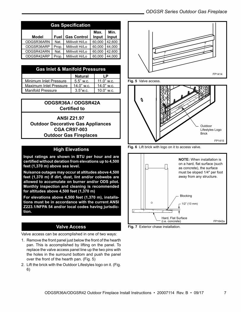
Valve AccessValve access can be accomplished in one of two ways:1. Remove the front panel just below the front of the hearth
pan. This is accomplished by lifting on the panel. To replace the valve access panel line up the two pins with the holes in the surround bottom and push the panel over the front of the hearth pan. (Fig. 5)
2. Lift the brick with the Outdoor Lifestyles logo on it. (Fig. 6)
ODGSR36A / ODGSR42ACertified to
ANSI Z21.97 Outdoor Decorative Gas Appliances
CGA CR97-003Outdoor Gas Fireplaces
FP1414�ODUVSRvalve access11/24/03 djt
FP1414
Fig. 5 Valve access.
FP1415�lift brick access11/24/03 djt
Outdoor Lifestyles Logo Brick
Fig. 6 Lift brick with logo on it to access valve.
FP1415
1/2” (13 mm)
FP1642aconcrete install9/06
NOTE: When installation is onahard,flatsurface(suchas concrete), the surface must be sloped 1/4" per foot away from any structure.
Blocking
Hard, Flat Surface(i.e. concrete) FP1642a
Fig. 7 Exterior chase installation.
8
ODGSR Series Outdoor Gas Fireplace
ODGSR36A/ODGSR42 Outdoor Fireplace Install Instructions • 20007114 Rev. B • 09/17
FP1416ODUVSRpart id11/24/03 djt
NailingFlange
Valve Access Panel
Firebox
Grate
Screen
StandoffSurround
Gas Line Ac-cess
FP1416
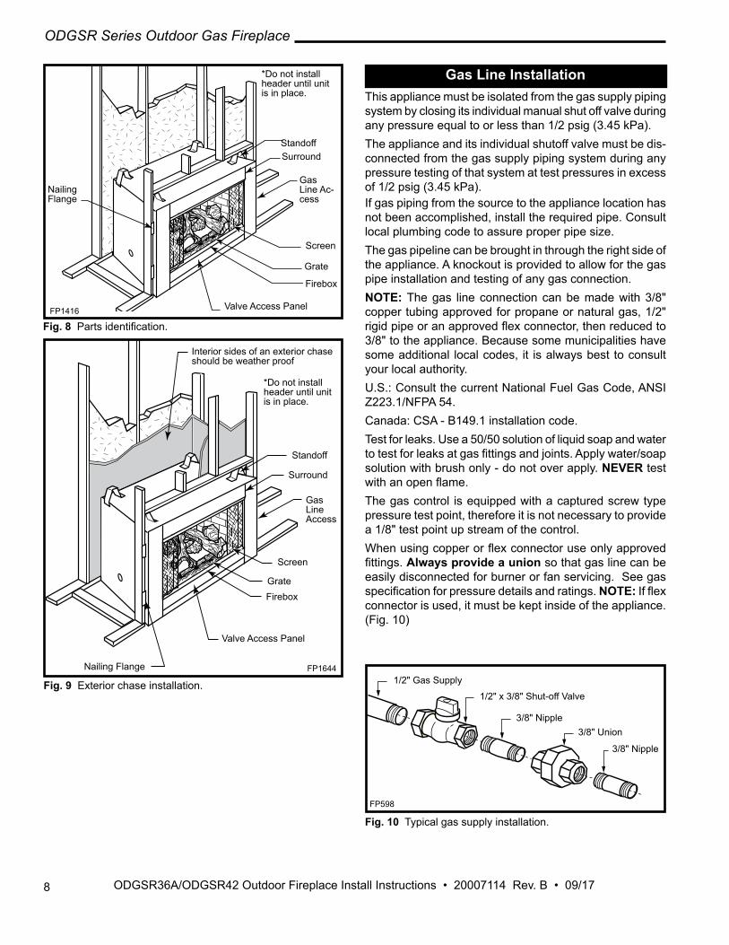
Fig. 8Partsidentification.
*Do not install header until unit is in place.
FP1416ODUVSRpart id11/24/03 djt
NailingFlange
Valve Access Panel
FireboxGrate
Screen
Standoff
Surround
Gas Line Access
*Do not install header until unit is in place.
Interior sides of an exterior chase should be weather proof
FP1644
Fig. 9 Exterior chase installation.
Gas Line InstallationThis appliance must be isolated from the gas supply piping system by closing its individual manual shut off valve during any pressure equal to or less than 1/2 psig (3.45 kPa).The appliance and its individual shutoff valve must be dis-connected from the gas supply piping system during any pressure testing of that system at test pressures in excess of 1/2 psig (3.45 kPa).If gas piping from the source to the appliance location has not been accomplished, install the required pipe. Consult local plumbing code to assure proper pipe size.The gas pipeline can be brought in through the right side of the appliance. A knockout is provided to allow for the gas pipe installation and testing of any gas connection. NOTE: The gas line connection can be made with 3/8" copper tubing approved for propane or natural gas, 1/2" rigidpipeoranapprovedflexconnector,thenreducedto3/8" to the appliance. Because some municipalities have some additional local codes, it is always best to consult your local authority. U.S.:ConsultthecurrentNationalFuelGasCode,ANSIZ223.1/NFPA54.Canada: CSA - B149.1 installation code.Test for leaks. Use a 50/50 solution of liquid soap and water totestforleaksatgasfittingsandjoints.Applywater/soapsolution with brush only - do not over apply. NEVER test withanopenflame.The gas control is equipped with a captured screw type pressure test point, therefore it is not necessary to provide a 1/8" test point up stream of the control.Whenusingcopperorflexconnectoruseonlyapprovedfittings.Always provide a union so that gas line can be easily disconnected for burner or fan servicing. See gas specificationforpressuredetailsandratings.NOTE:Ifflexconnector is used, it must be kept inside of the appliance. (Fig. 10)
FP598
Fig. 10 Typical gas supply installation.
GF598nvb GAS SUPPLY INSTALL12/4/97
1/2" Gas Supply
1/2" x 3/8" Shut-off Valve
3/8"Nipple3/8" Union
3/8"Nipple
9
ODGSR Series Outdoor Gas Fireplace
ODGSR36A/ODGSR42 Outdoor Fireplace Install Instructions • 20007114 Rev. B • 09/17
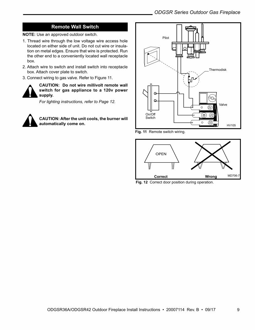
Remote Wall Switch NOTE: Use an approved outdoor switch.1. Thread wire through the low voltage wire access hole
located on either side of unit. Do not cut wire or insula-tion on metal edges. Ensure that wire is protected. Run the other end to a conveniently located wall receptacle box.
2. Attach wire to switch and install switch into receptacle box. Attach cover plate to switch.
3. Connect wiring to gas valve. Refer to Figure 11.
CAUTION: Do not wire millivolt remote wall switch for gas appliance to a 120v power supply. For lighting instructions, refer to Page 12.
CAUTION: After the unit cools, the burner will automatically come on.
MD706-7Glass Door Position1/20/99
OPEN
Correct Wrong MD706-7
Fig. 12 Correct door position during operation.
Pilot
Thermodisk
On/Off Switch
Valve
HV105
Fig. 11 Remote switch wiring.
HV105Generic Gas Valve9/22/99 djt
TP
TH
TH
TP

10
ODGSR Series Outdoor Gas Fireplace
ODGSR36A/ODGSR42 Outdoor Fireplace Install Instructions • 20007114 Rev. B • 09/17
Operating InstructionsLog Installation
1. Remove logs from the packaging. As with all plastic, these bags are not toys and should always be kept away from children and infants.
2. Place left rear log on rear log support. Ensure that log is firmly positioned andthere is no side-to-side movement. (Figs. 13 & 14)
3. Carefully place Ember Log between grate and burner. (Figs. 13 & 14)
4. Place the front of right rear log on the burner and the back of the log on the rear log support.
5. Place the top logs onto the locator notches. Ensure the logs are secure. (Fig. 13 & 14)
First FiringUpon completing the gas line connection, a small amountofairwillbetrappedintheline.Whenfirstlighting the unit with pilot light, it will take a few minutes to purge the trapped air. Once purging is complete, the pilot and burner will light and operate as indicated in the instruction manual. Subsequent lightings of the appliance will not require purging. Whenlitforthefirsttime,theappliancewillemitaslight odor for an hour or two. This is due to paint and lubricants used in the manufacturing process. After each lighting, vapor may condense and fog the glass; this moisture disappears in a few minutes of burning.
LG317�
UVODSR36
logs
11/24/03 djt
Right Cross Log
Left Cross Log
Left Rear Log
Right Rear Log
Ember Log
LG317
Fig. 13 ODGSR36 log placement.
LG318ODUVSR42log set11/24/03 djt
Left Rear Log
Left Cross Log
Middle Cross Log
Right Cross Log
Right Rear Log
Log Left Ember
Grate
Fig. 14 ODGSR42A log placement.
LG318
Log Right Ember
11
ODGSR Series Outdoor Gas Fireplace
ODGSR36A/ODGSR42 Outdoor Fireplace Install Instructions • 20007114 Rev. B • 09/17
LG320
ODUVSR42
log flames
11/24/03 djt
LG320
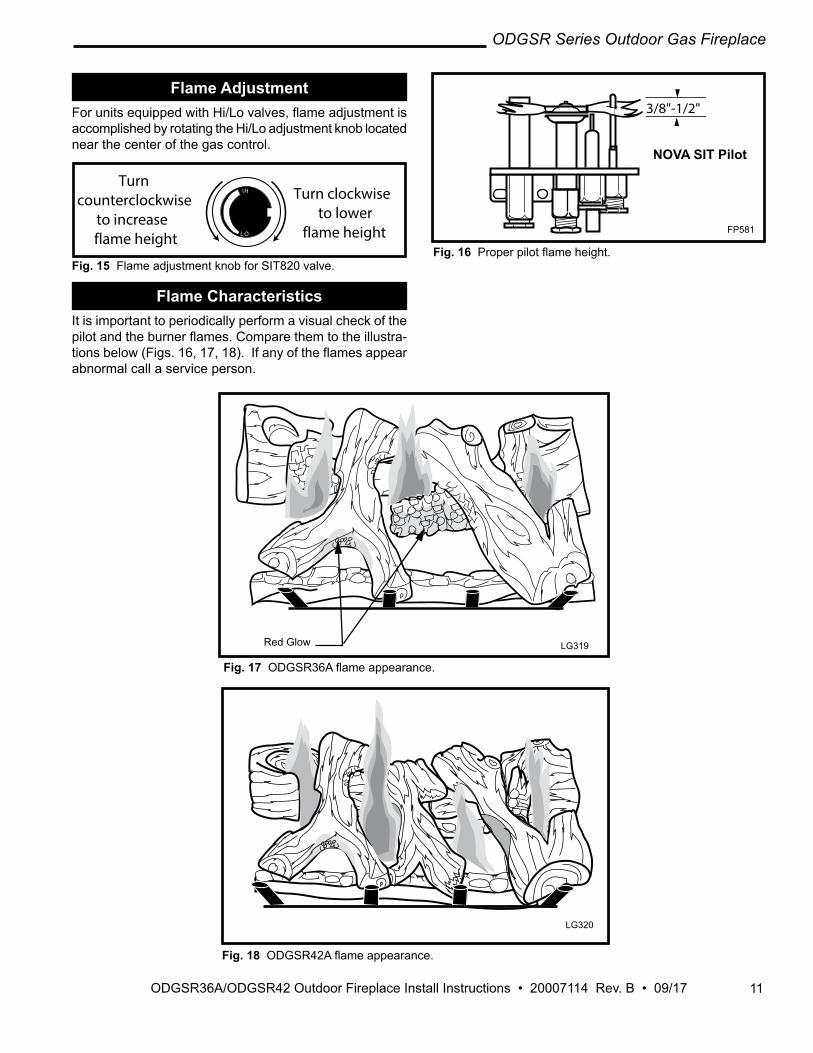
Fig. 18ODGSR42Aflameappearance.
Fig. 16Properpilotflameheight.
FP581
3/8"-1/2"
FP581NVB-PILOTS12/4/97
ELECTRONIC�IGNITION
NOVA SIT Pilot
LG319ODUVSR36log flames11/24/03 djt
Red Glow LG319
Fig. 17 ODGSR36Aflameappearance.
Flame AdjustmentForunitsequippedwithHi/Lovalves,flameadjustmentisaccomplished by rotating the Hi/Lo adjustment knob located near the center of the gas control.
L O
HITurn counterclockwise
to increase flame height
Turn clockwiseto lower
flame height
FP390FLAME ADJUSTMENT KNOB11/21/96
Fig. 15 Flame adjustment knob for SIT820 valve.
Flame CharacteristicsIt is important to periodically perform a visual check of the pilotandtheburnerflames.Comparethemtotheillustra-tionsbelow(Figs.16,17,18).Ifanyoftheflamesappearabnormal call a service person.

12
ODGSR Series Outdoor Gas Fireplace
ODGSR36A/ODGSR42 Outdoor Fireplace Install Instructions • 20007114 Rev. B • 09/17
Optional Weather EnclosureAn optional weather enclosure is available to protect the burner when not in use.
Installation Instructions
1. Turn the unit OFF and allow to cool.2. Grab the weather enclosure by the handle(s).3. Slide the top of the weather enclosure up between the
back of the surround top and the screen rail. (Fig. 19)4. Pushthebottomoftheweatherenclosureintothefire-
box just enough to clear the valve access cover and set down. (Fig. 20)
KT457place we top4/1/04 djt
KT457
Fig. 19 Place top of weather enclosure between surround top and screen rail.
Surround Top
Weather EnclosureScreen Rail
KT458place we bottom 4/1/04 djt
Screen
Hearth Brick
Valve Access Cover
KT458
Fig. 20Pushbottomofweatherenclosureintofirebox.
Optional Stainless Steel HoodAn optional stainless steel hood is available for both the ODGSR36A and ODGSR42A.Installation Instructions:1. Turn the unit off and allow to cool.2. Place the hood so the25⁄8" (67 mm) slot clears the sen-
sorplate locatedunder thefireplaceopeningon thetop left side. (Fig. 21)
3. Secure the hood to the unit using the three (3) slots in the hood and the pilot holes in the unit with the stain-less steel sheet metal screws provided. (Fig. 21)
4. Align the sides of the hood so the pilot holes on the right and left sides of the unit are exposed through the slots on the ends of the hood. Secure using the re-maining stainless steel sheet metal screws. (Fig. 21)
FP1635ODGSR hood6/06
Stainless Steel Hood
Stainless Steel Sheet
Metal Screws (5)
Sensor Plate Slot
FP1635
Fig. 21Securestainlesssteelhoodwithfive(5)sheetmetalscrews.

13
ODGSR Series Outdoor Gas Fireplace
ODGSR36A/ODGSR42 Outdoor Fireplace Install Instructions • 20007114 Rev. B • 09/17
3. Open control access panel.4. Push in gas control knob slightly and turn clock-
wise to "OFF". Do not force.5. Close control access panel.
1. STOP! Read the safety information above.2. Turn OFFallelectricalpowertothefireplace.3. ForMN/MP/TN/TPappliancesONLY,goontoStep
4.ForRN/RPappliancesturntheOn/Offswitchto“OFF”positionorsetthermostattolowestlevel.
4. Open control access panel.5. Push in gas control knob slightly and turn clock-
wise to "OFF".6. Waitfive(5)minutestoclearoutanygas.Then
Immediately light the pilot by repeatedly depress-ing thepiezospark ignitoruntil a flameappears.Continue to hold the control knob in for about one (1) minute after the pilot is lit. Release knob and it will pop back up. Pilot should remain lit. If it goes out, repeat steps 5 through 8.
• If knob does not pop up when released, stop and immediately call your service technician or gas
FOR YOUR SAFETY READ BEFORE LIGHTING
• If you cannot reach your gas supplier, call the Fire Department
C. Use only your hand to push in or turn the gas control knob.Neverusetools.Iftheknobwillnotpushinorturnbyhand,donottrytorepairit,callaqualifiedservice technician. Applying force or any attempted repairmayresultinafireorexplosion.
D.Donotusethisfireplaceifanyparthasbeenunderwater.Immediatelycallaqualifiedservicetechnicianto inspect the heater and to replace any part of the control system and any gas control which has been under water.
A. This heater has a pilot which must be lit manu-ally. When lighting the pilot follow these instructions exactly.
B.BEFORELIGHTINGsmellallaroundtheheaterareaforgas.Besuretosmellnexttothefloorbecause some gas is heavier than air and will settleonthefloor.
WHAT TO DO IF YOU SMELL GAS• Donottrytolightanyfireplace• Do not touch any electric switch• Do not use any phone in your building• Immediately call your gas supplier from a neigh-
bor's phone. Follow the gas supplier's instruc-tions.
To Turn Off Gas to Heater
Lighting and Operating Instructions
1. Turn the On/Off switch to "OFF" position or set the thermostat to lowest setting.
2. Turn off all electric power to the fireplace ifservice is to be performed.
Lighting Instructions
smellforgas,includingnearthefloor.Ifyousmellgas, STOP! Follow "B" in the safety information above. If you do not smell gas, go to the next step.
7. Remove glass door before lighting pilot. (See Glass Frame Removal section).
8. Visibly locate pilot by the main burner.9. Turn knob on gas control counterclockwise
to "PILOT".10. Push the control knob all the way in and hold.
supplier. • If after several tries, the pilot will not stay lit,
turn the gas control knob to "OFF" and call your service technician or gas supplier.
11. Replace glass door.12.Turngascontrolknobto“ON”position.13.ForRN/RPappliancesturntheOn/Offswitchto“ON”
position or set thermostat to desired setting.14.Turnonallelectricalpowertothefireplace.
WARNING:If you do not follow these instructions exactly, a fire or explosion may result causing property damage, personal injury or loss of life.
Euro SIT SIT NOVA Honeywell
PILOT
ON
OFF
ON
P IL OT
OFF
OFF
FP1067lighting instructionknobs3/9/01 djt
5 4 3
21
OFF
Pilo
t
3/8" - 1/2"
FP1068Lighting instructionsPilots

14
ODGSR Series Outdoor Gas Fireplace
ODGSR36A/ODGSR42 Outdoor Fireplace Install Instructions • 20007114 Rev. B • 09/17
Troubleshooting
FP396
Gas Supply On Supply Line Hooked upShuto� Valve Open
NO
NO
NO
NO
Lockout has engaged. Wait 60 seconds and try again.Piezo not tight enough for good ground.For spark at electrode while depressing Piezo (Red Button) 1/8" gap to pilot hood needed.All wiring connectionsReplace Piezo IgnitorThermodisk
For Air in the linesThermopile needs a minimum 325mV. Adjust pilot �ame height.All wiring connectionsReplace ThermopileThermocouple needs a minimum of 14mV.Defective valve. Turn to pilot, meter should read greater than 100mV.Thermodisk
Pilot Lights withPiezo Ignitor
YES
YES
YES
YES
Pilot Stays Lit
Pilot Lights MainBurner
System OK
STARTCHECK
Wall switch is not turned on. Watch for grounded wires!Thermopile needs a minimum 325mVPlugged burner ori�ce
FP396NVC-standing pilot troubleshooting5/6/98
Nova SIT 820 Standing Pilot

15
ODGSR Series Outdoor Gas Fireplace
ODGSR36A/ODGSR42 Outdoor Fireplace Install Instructions • 20007114 Rev. B • 09/17
MaintenanceBurner and Burner Compartment
It is important to keep the burner and the burner compartment clean. At least once per year the logs should be removed and the burner compartment vacuumed and wiped out. Remove and replace the logs as per the instructions in this manual.Always handle the logs with care as they are fragile and may also be hot if the fireplace has been in use.
CleaningThere are three methods of cleaning the polished stainless steelofyouroutdoorfireplace;1. Warm,soapywater-toloosenanydirtfilm2. Glass cleaner with ammonia3. Stainless steel cleaner available at hardware storesRegardless of which method is used, remember that any-thingwithtoomuchabrasivemaydullthefinish.
Cleaning the Standing Pilot Control System
The burner and control system consists of:
• main burner • gasorifice• pilot burner• thermopile• combination millivolt gas valve
Most of these components may require only an occasional checkup and cleaning and some may require adjustment. Ifrepairisnecessary,itshouldbeperformedbyaqualifiedtechnician.In order to properly clean the burner and pilot assembly, turn off the gas to the unit, remove logs exposing the burner and pilot assembly. Clean all foreign materials from the top of the burner. Check to make sure that burner parts are clean. Visually inspect pilot. Brush or blow away any dust orlintaccumulationIfpilotorificeisplugged,disassemblymay be required to remove any foreign material from the orificeortubing.To obtain proper operation, it is imperative that the pilot andburner'sflamecharacteristicsaresteady,not liftingorfloating.Typically, the top 3/8" or 1/2" of the thermopile should be engulfedinthepilotflame.(Fig.16)To adjust pilot burner, turn pilot screw marked "pilot" for properflamesize.The air shutter is set at factory no adjustment should be necessary.

16
ODGSR Series Outdoor Gas Fireplace
ODGSR36A/ODGSR42 Outdoor Fireplace Install Instructions • 20007114 Rev. B • 09/17
7114oduvsr36/42Aparts11/24/03 DJT
4a/b
11
13
HI
L
O OFF
ON
O
FF
EA
PILOT
THTP
TPTH
12a/b
16
15
18a/b
69 10
a b
d
c
h
c
da
b
f
e
2
3
7
8
17
g
19a/b
21
22
25
ODGSR36A, ODGSR42A Ref. Description ODGSR36A ODGSR42A 1. Logs - Complete Set 20007180K 20007200K 1a. Log - Left Rear 20007175K 20007193 1b. Log - Right Rear 20007176K 20007194K 1c. Log - Right Cross 20007178K 20007197K 1d. Log - Left Cross 20007177K 20007195K 1e. Log - Middle Cross -- 20007196K 1f. Log - Left Ember -- 20007198K 1g. Log - Right Ember -- 20007199K 1h. Front Ember Log 20007179K -- 2. Burner Housing Assembly 20007119K 20007187K 3. Ceramic Tile (single) 57803 57803 4a. BurnerOrifice-Natural(Manifold&Orifice) 20007106 20007106 4b. BurnerOrifice-LP(Manifold&Orifice) 20007159 20007159 6. Side Brick - Left* 20002008K 20002008K 7. Back Brick* 20002006K 20002019K 8. Side Brick - Right* 20002007K 20002007K 9. Left Hearth Brick* 20007158K 20007241K 10. Right Hearth Brick* 20007157K 20007240K 11. Piezo 057958 057958 12a. PilotTopConvertible-Natural(3WayAssembly) 10002264 10002264 12b. Pilot Top Convertible - LP (3 Way assembly) 10002265 10002265 13. Thermopile 18" 26D0566 26D0566
Hearth&HomeTechnologiesreservestherighttomakechangesindesign,materials,specifications,pricesanddiscontinuecolorsandproductsat any time, without notice.
7114
1. ODGSR36A Logs 1. ODGSR42A Logs
17
ODGSR Series Outdoor Gas Fireplace
ODGSR36A/ODGSR42 Outdoor Fireplace Install Instructions • 20007114 Rev. B • 09/17
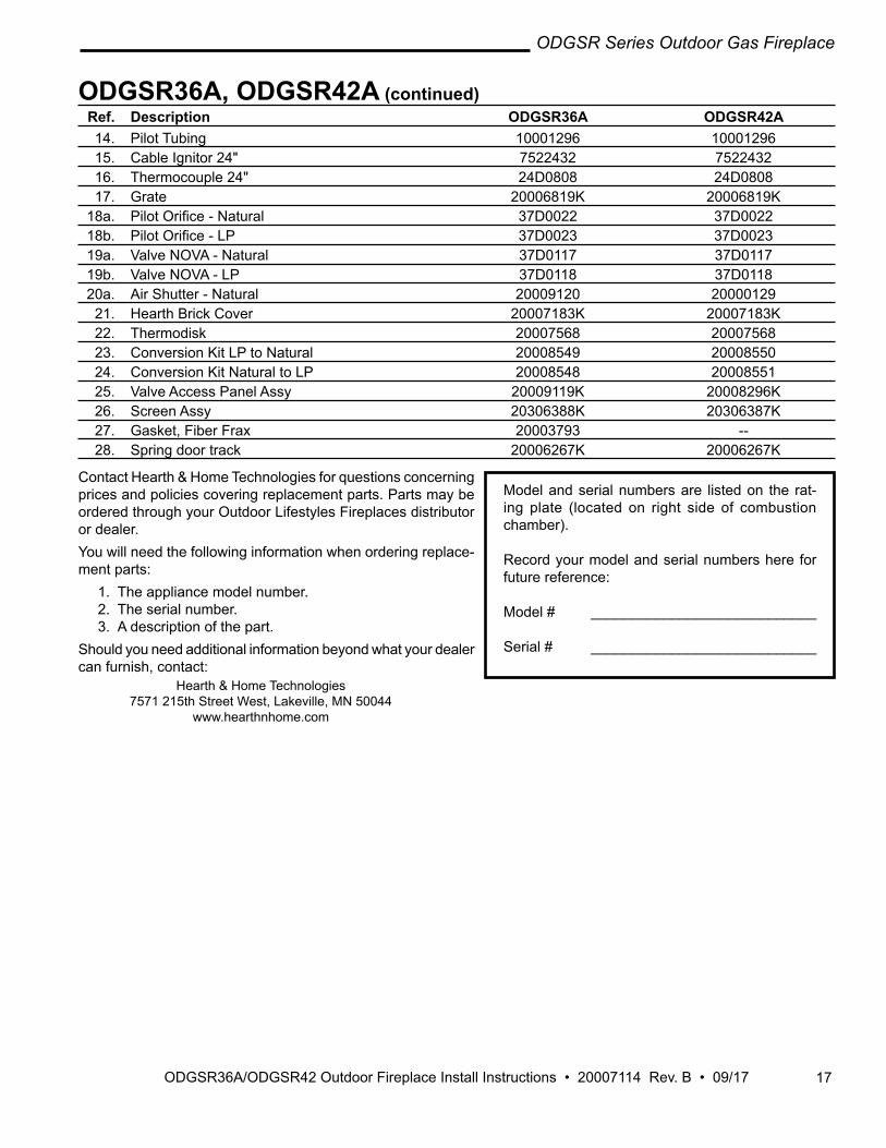
ODGSR36A, ODGSR42A (continued) Ref. Description ODGSR36A ODGSR42A 14. Pilot Tubing 10001296 10001296 15. Cable Ignitor 24" 7522432 7522432 16. Thermocouple 24" 24D0808 24D0808 17. Grate 20006819K 20006819K 18a. PilotOrifice-Natural 37D0022 37D0022 18b. PilotOrifice-LP 37D0023 37D0023 19a. ValveNOVA-Natural 37D0117 37D0117 19b. ValveNOVA-LP 37D0118 37D0118 20a. AirShutter-Natural 20009120 20000129 21. Hearth Brick Cover 20007183K 20007183K 22. Thermodisk 20007568 20007568 23. ConversionKitLPtoNatural 20008549 20008550 24. ConversionKitNaturaltoLP 20008548 20008551 25. Valve Access Panel Assy 20009119K 20008296K 26. Screen Assy 20306388K 20306387K 27. Gasket, Fiber Frax 20003793 -- 28. Spring door track 20006267K 20006267K
Contact Hearth & Home Technologies for questions concerning prices and policies covering replacement parts. Parts may be ordered through your Outdoor Lifestyles Fireplaces distributor or dealer.You will need the following information when ordering replace-ment parts:
1. The appliance model number.2. The serial number.3. A description of the part.
Should you need additional information beyond what your dealer can furnish, contact:
Model and serial numbers are listed on the rat-ing plate (located on right side of combustion chamber).
Record your model and serial numbers here for future reference:
Model # ____________________________
Serial # ____________________________
Hearth & Home Technologies 7571215thStreetWest,Lakeville,MN50044
www.hearthnhome.com

18
ODGSR Series Outdoor Gas Fireplace
ODGSR36A/ODGSR42 Outdoor Fireplace Install Instructions • 20007114 Rev. B • 09/17
AccessoriesThe following accessories are available from your local Outdoor Lifestyles Fireplaces distributor. Each accessory comes withaseparateinstallationinstructionformountingtotheparticularfirebox.Besuretoreadeachinstructionthoroughlybefore installing.
CAUTION: This firebox is a highly engineered system, and must be operated only with Hearth & Home Technol-ogies approved components. If you use an unapproved component to make any modifications, you may create a possible fire hazard and will void the warranty. In addition, such action may void the coverage provided by the owner's insurance.
Accessory Description Model Number 4" Stainless Steel For heater up to 40,000 BTU's and mantels UV36SH4 Hood 8" high by 12" wide UV42SH4 Weather Enclosure Designed to protect the burner when unit is not in use ODG36WE ODG42WE

19
ODGSR Series Outdoor Gas Fireplace
ODGSR36A/ODGSR42 Outdoor Fireplace Install Instructions • 20007114 Rev. B • 09/17
LIMITED LIFETIME WARRANTY PRODUCT COVERED BY THIS WARRANTYAllVermontCastingsgasstoves,gasinserts,andgasfireplaces,andallMonessenandOutdoorLifestylesbrandgasfireplacesequippedwithanInsta-FlameCeramicBurner,orstandardsteeltube burner.BASIC WARRANTY Outdoor Lifestyles (hereinafter referred to collectively as the Company)
warrants that your new Vermont Castings, Monessen or Outdoor Lifestyles Gas Fireplace/Stove is free from manufacturing and material defects for a period of one year from the date of purchase, subject to the following conditions and limitations.
EXTENDED LIFETIME WARRANTY The heat exchanger, where applicable, and combustion chamber of
every Vermont Castings, Monessen or Outdoor Lifestyles gas product is warranted for life against through wall perforation. All appliances equipped with an Insta-Flame Ceramic Burner have limited lifetime coverage on the ceramic burner plaque. Warrantees are made to the original owner subject to proof of purchase and the conditions and limitations listed on this Warranty Document
COMPONENT WARRANTYCASTIRON:Allexternalandinternalcastironpartsarewarrantedforaperiod of three years. Note:OnporcelainenamelfinishedexternalpartsandaccessoriesThe
Company offers no Warranty on chipping of enamel surfaces. Inspect all product prior to accepting it for any damage to the enamel.
The salt air environment of coastal areas or a high humidity environment canbecorrosivetotheporcelainenamelfinish.Theseconditionscancauserustingof thecast ironbeneath theporcelainenamelfinish,whichwillcausethefinishtoflakeoff.
Dye lot variations with replacement parts and/or accessories can occur and are not covered by warranty.
BRASSPLATEDPARTSANDACCESSORIES:Brasspartsshouldbecleaned with Lemon oil only. Brass cleaners cannot be used. Mortar mix andmasonrycleanersmaycorrodethebrassfinish.TheCompanywillnotbe responsible for, nor will it warrant any brass parts which are damaged by external chemicals or down draft conditions.GAS VALVES: Gas valves are covered for a period of one yearELECTRONICANDMECHANICALCOMPONENTS: Electronic andmechanical components of the burner assembly are covered for one year. All steel tube burners are warranted for one year.ACCESSORIES: Unless otherwise noted, all components and Outdoor Lifestyles company supplied accessories are covered for a period of one year.CONDITIONS AND LIMITATIONS• This Vermont Castings or Outdoor Lifestyles product must be installed
orservicedbyaqualifiedinstaller,preferablyNFIorWETT(Canada)certified,asprescribedbythelocaljurisdiction.Itmustbeinstalledandoperated at all times in accordance with the Installation and Operating instructions furnished with the product. Any alteration, willful abuse, accident, or misuse of the product shall nullify this warranty.
• This warranty is non-transferable, and is made to the original owner, provided that the purchase was made through an authorized supplier of the Company.
• The customer must pay for any Authorized Dealer in-home travel fees or service charges for in-home repair work. It is the dealers option whether the repair work will be done in the customer’s home or in the dealer’s shop.
• If upon inspection, the damage is found to be the fault of the manufacturer, repairs will be authorized at no charge to the customer parts and/or labor.
• Any part and/or component replaced under the provisions of this warranty is covered for six months or the remainder of the original warranty, whichever is longest.
• This warranty is limited to the repair of or replacement of part(s) found
to be defective in material or workmanship, provided that such part(s) have been subjected to normal conditions of use and service, after saiddefectisconfirmedbytheCompany’sinspection.
• The company may, at its discretion, fully discharge all obligations with respect to this warranty by refunding the wholesale price of the defective part(s)
• Any installation, labor, construction, transportation, or other related costs/expenses arising from defective part(s), repair, replacement, or otherwise of same, will not be covered by this warranty, nor shall the Company assume responsibility for same. Further, the Company will not be responsible for any incidental, indirect, or consequential damages except as provided by law.
• SOME STATESDONOTALLOW FORTHE EXCLUSIONORLIMITATIONSOFINCIDENTALANDCONSEQUENTIALDAMAGESOR LIMITATIONSON HOW LONGAN IMPLIEDWARRANTYLASTS,SOTHEABOVELIMITATIONSMAYNOTAPPLYTOYOURCIRCUMSTANCES. THISWARRANTYGIVESYOUSPECIFICRIGHTSANDYOUMAYHAVEOTHERRIGHTSWHICHVARYFROMSTATE TO STATE.
• All other warranties-expressed or implied- with respect to the product, its components and accessories, or any obligations/liabilities on the part of the Company are hereby expressly excluded.
• The Company neither assumes, nor authorizes any third party to assume on its behalf, any other liabilities with respect to the sale of this Vermont Castings, Monessen or Outdoor Lifestyles product
• The warranties as outlined within this document do not apply to chimney components or other non-Outdoor Lifestyles accessories used in conjunction with the installation of this product.
• Damage to the unit while in transit is not covered by this warranty but is subject to claim against the common carrier. Contact the dealer fromwhomyoupurchasedyourfireplace/stove(donotoperatetheappliance as this might negate the ability to process the claim with the carrier).
• The Company will not be responsible for:a) Down drafts or spillage caused by environmental conditions such
as near-by trees, buildings, roof tops, hills, or mountains.b) Inadequate ventilation or negative air pressure caused by
mechanical systems such as furnaces, fans, clothes dryers, etc.• This warranty is void if:
a) Thefireplacehasbeenoperatedinatmospherescontaminatedbychlorine,fluorine,orotherdamagingchemicals.
b) The fireplace has been subjected to prolonged periods of dampness or condensation
c) Any damages to the fireplace, combustion chamber, heat exchanger or other components due to water, or weather damage, which is the result of but not limited to, improper chimney/venting installation.
d) Any alteration, willful abuse, accident, or misuse of the product has occurred.
IF WARRANTY SERVICE IS NEEDED…1) Contact your supplier. Make sure you have your warranty, your
sales receipt, and the model/serial number of your Outdoor Lifestyles product.
2) DO NOT ATTEMPT TO DO ANY SERVICE WORKYOURSELF.

ODGSR36A/ODGSR42 Outdoor Fireplace Install Instructions • 2007114 Rev. A • 03/17
Hearth & Home Technologies 7571215thStreetWest,Lakeville,MN50044
www.hearthnhome.com