OUTDOOR FIRE PIT MANUAL - Marquis Fireplaces · OUTDOOR FIRE PIT MANUAL . MODELS FP2085 ROUND FIRE...
20
OUTDOOR FIRE PIT MANUAL MODELS FP2085 ROUND FIRE PIT, FP2785 RECTANGULAR FIRE PIT CERTIFIED FOR USA & CANADA Owner’s Operation and Installation Manual STANDARDS: CR97-003, ANSI Z21.97-2010 OUTDOOR DECORATIVE GAS APPLIANCES ⚠DANGER If you smell gas: 1. Shut off gas to the appliance. 2. Extinguish any open flame. 3. If odor continues, keep away from the appliance and immediately call your gas supplier or fire department. ⚠WARNING Do not store or use gasoline or other flammable vapors and liquids in the vicinity of this or any other appliance. An LP-cylinder not connected for use shall not be stored in the vicinity of this or any other appliance. ⚠WARNING For Outdoor Use Only. ⚠WARNING Improper installation, adjustment, alteration, service or maintenance can cause injury or property damage. Read the installation, operating and maintenance instructions thoroughly before installing or servicing this equipment. ⚠ DANGER CARBON MONOXIDE HAZARD This appliance can produce carbon monoxide which has no odor. Using it in an enclosed space can kill you. Never use this appliance in an enclosed space such as a camper, tent, car or home. Kingsman Fireplaces 2340 Logan Ave., Winnipeg, Mb Canada Ph: 204-632-1962 Printed in Canada P/N 27FP-MAN June 19, 2014 INSTALLER: Leave this manual with the appliance. CONSUMER: Retain this manual for future reference. This appliance is designed as an “attended appliance”. Adults must be present when the unit is operating. DO NOT leave this unit burning when unattended. If this product is left burning unattended it may cause damage or serious injury.
Transcript of OUTDOOR FIRE PIT MANUAL - Marquis Fireplaces · OUTDOOR FIRE PIT MANUAL . MODELS FP2085 ROUND FIRE...

OUTDOOR FIRE PIT MANUAL MODELS FP2085 ROUND FIRE PIT, FP2785 RECTANGULAR FIRE PIT
CERTIFIED FOR USA & CANADA
Owner’s Operation and Installation Manual STANDARDS: CR97-003, ANSI Z21.97-2010
OUTDOOR DECORATIVE GAS APPLIANCES
⚠DANGER
If you smell gas: 1. Shut off gas to the appliance. 2. Extinguish any open flame. 3. If odor continues, keep
away from the appliance and immediately call your gas supplier or fire department.
⚠WARNING Do not store or use gasoline or other flammable vapors and liquids in the vicinity of this or any other appliance. An LP-cylinder not connected for use shall not be stored in the vicinity of this or any other appliance.
⚠WARNING For Outdoor Use Only.
⚠WARNING Improper installation,
adjustment, alteration, service or maintenance can cause injury or property damage.
Read the installation, operating and maintenance
instructions thoroughly before installing or servicing this
equipment.
⚠ DANGER CARBON MONOXIDE HAZARD This appliance can produce carbon monoxide which has no odor. Using it in an enclosed space can kill you. Never use this appliance in an enclosed space such as a camper, tent, car or home.
Kingsman Fireplaces 2340 Logan Ave., Winnipeg, Mb Canada Ph: 204-632-1962 Printed in Canada P/N 27FP-MAN June 19, 2014
INSTALLER: Leave this manual with the appliance.
CONSUMER: Retain this manual for future reference.
This appliance is designed as an “attended appliance”. Adults must be present when the unit is operating. DO NOT leave this
unit burning when unattended. If this product is left burning unattended it may cause damage or serious injury.

Product Maintenance For Your Canvas Fire Pit Cover
Caring for your Fire Pit Cover The key to keeping your outdoor fabric looking great and extending its life is periodic cleaning followed by repellency treatment. Mildew can be a problem for any outdoor fabric. Mildew will not grow on a clean synthetic fabric. Combined with humidity, the dirt and debris, which accumulate on and in the fabric, create the ideal conditions for mildew propagation. Thus keeping outdoor fabric both clean and dry is essential to eliminate or minimize mildew growth.
* Brush surfaces with soft brush to remove soil. * Soak with warm, soapy water (not to exceed 100 degrees Fahrenheit). * Use a mild soap such as Ivory, or Dawn. Do not use detergents, abrasives or cleaners. * Rinse fabric thoroughly after cleaning. * Let fabric air dry after rinsing * Do not machine dry. Treating your Fabric * Before "retreating" or "protecting" a fabric, the fabric must be thoroughly cleaned. Fabric protector products bond most effectively to perfectly clean fabric. Anything not removed from the fabric will interfere with the bonding and performance of the product. All dirt, body oils, sweat, soap residue will impede bonding and performance. * Do not over spray. Saturation is not necessary. The surface needs to be slightly damp, but not soaked. Two lighter coats are better than one heavy coat. An even coating is more likely with two applications. Let the first coating dry to the touch before applying the second - generally an hour. * The quicker you can get a fabric protector product to dry, the better bonding and performance you will achieve. It is best to treat the fabrics in warm weather, such as a hot day in full sun. * Maintenance is essential. You can lightly mist the surface every 6 months to check the water repellency. Friction will wear away product more quickly leaving the fabric unprotected. If this is the case, such areas can be spot treated to renew repellency. * Just a note - Silicone water repellents are not true "fabric protectors". While they do develop good repellency, they often retain a tackiness that attracts dirt. Silicone treated fabrics soil much more rapidly than untreated fabrics, have no resistance to oil based stains, and can make fabrics more difficult to clean once soiled.
Fabric Guard Recommended as the best fabric protectant 303® High Tech Fabric Guard™ is a premium patented formula that restores fabrics lost water and stain repellency. Yearly maintenance with 303 Products will add to the life of your fabrics
Stainless Steel Parts And Accessories
NOTE: The protective wrap on stainless steel parts is best removed at room temperature. A hair dryer may be helpful.
Cleaning Stainless Steel Stainless steel tends to oxidize or stain in the presence of chlorides and sulfides, particularly in coastal areas and other harsh environments, such as the warm, highly humid atmosphere around pools and hot tubs. These stains could be perceived as rust, but can be easily removed or prevented. To provide stain prevention and removal, wash all stainless steel surfaces every 3-4 weeks or as often as required with fresh water and/or stainless steel cleaner.
Notes on Cleaning Stainless Steel Surfaces: Do not use abrasive cleaners or steel wool on any painted, or stainless steel parts. Doing so will scratch the finish. Exterior surfaces should be cleaned with warm soapy water. Use a stainless steel or a non-abrasive cleaner. Always wipe in the direction of the grain.
Over time, stainless steel parts discolor when heated, usually to a golden or brown hue. This discoloration is normal and does not affect the performance of the appliance.
2

Table of Contents
Product Maintenance For Your Canvas Fire Pit Cover / Stainless Steel Parts And Accessories………… 2
Table Of Contents...................................................................................................................................... 3
Introduction.................................................................................................................................................. 4
Assembly And Installation........................................................................................................................... 5
Gas Specifications...................................................................................................................................... 6
Installation In Combustible Enclosure......................................................................................................... 7
Installing Rectangle Fire Pit Into A Wood Enclosure................................................................................... 8
Installing Wall Clearance Shield................................................................................................................. 9
FP2085 Fire Pit Assembly........................................................................................................................... 10
FP2785 Burner Assembly........................................................................................................................... 11
Log Placement Instructions......................................................................................................................... 12
Accessories For Your Fire Pit...................................................................................................................... 13
30FPB-KWK Decorative Key Way Valve Kit............................................................................................... 14
Kingsman Outdoor Fire Pit Media Section.................................................................................................. 15-16
Operating Instructions................................................................................................................................. 17
Maintenance Instructions............................................................................................................................ 17
High Elevation Installation........................................................................................................................... 17
Safety Information And Lighting Instructions............................................................................................... 18
FP2085/FP2785 Parts List.......................................................................................................................... 19
Kingsman Fireplaces Gas Fire Pit – Limited Warranty............................................................................... 20
3

INTRODUCTION Models FP2085/FP2785 are Decorative Gas Log Set for outdoor use only. This appliance MUST NOT be used for cooking.
WARNING: This appliance shall be used ONLY outdoors in a well-ventilated space and shall NOT be used inside a building, garage, or any other enclosed area.
WARNING: This log set must NOT be installed in an unvented appliance.
WARNING: THIS UNIT IS NOT FOR USE WITH SOLID FUEL.
The installation must conform with Local codes ore in the absence of local codes, with the National Fuel Gas Code ANSI Z223.1 or CAN/CGA-B149.1, National Gas Installation Code or CAN/CGA-B149.2, Propane installation Code.
The appliance and its individual shut off valve must be disconnected from the gas supply piping system during any pressure testing of the system at test pressures in excess of 1/2 psig (3.5kPa).
This appliance must be isolated from the gas supply piping system by closing its individual manual shut off valve during any pressure testing of the gas supply piping system at test pressures equal to or less than 1/2 psig (3.5kPa).
The following clearances to combustible construction must be maintained: Bottom - 0 inches Sides (all around)-24 inches (610 mm), and Top-7 feet (2.12 m).
Always keep the appliance area clear and free from combustible materials, gasoline, and other flammable vapors and liquids.
Do not locate appliance where it can get excessively wet. Do not use this appliance if any part has been under water. Immediately call a qualified service technician to inspect the unit and to replace any part of the control system and any gas control which has been underwater.
When an appliance is for connection to a fixed piping system, the installation must conform with local codes, or in the absence of local codes with the National Fuel Gas Code, ANSI Z223.1/NFPA 54, or International Fuel Gas Code.
For appliances for fixed fuel piping system and equipped with an appliance gas pressure regulator, the appliance and its individual shutoff valve must be disconnected from the gas supply piping system during any pressure testing of that system at test pressures in excess of 1/2 psi (3.5 kPa).
Children and adults should be alerted to the hazards of high surface temperatures and should stay away to avoid burns or clothing ignition.
Young children should be carefully supervised when they are in the area of the appliance.
Clothing or other flammable materials should not be hung from the appliance, or placed on or near the appliance.
Any guard or other protective device removed for servicing the appliance must be replaced prior to operating the appliance.
Installation and repair should be done by a qualified service person. The appliance should be inspected before use and at least annually by a qualified service person. More frequent cleaning may be required as necessary. It is imperative the control compartment, burners and circulating air passageways of the appliance be kept clean.
Inspect the fuel supply connection (including the hose for LP models) before each use of the appliance.
If it is evident there is excessive abrasion or wear, or the hose is cut, it must be replaced prior to the appliance being put into operation.
Cylinders must be stored outdoors in a well ventilated area out of the reach of children. Disconnected cylinders must have threaded valve plugs tightly installed and must not be stored in a building, garage or any other enclosed area.
Storage of this appliance indoors is permissible only if it has been disconnected from its fuel supply (natural gas line or LP gas cylinder).
LP GAS WARNINGS The LP gas supply cylinder used with LP models must be constructed and marked in accordance with the specifications for LP-gas cylinders of the U.S. Department of Transportation (DOT).
The pressure regulator and hose assembly supplied with LP models must be used. Replacement pressure regulators and hose assemblies must be those specified in this manual.
The LP gas cylinder supply system must be arranged for vapor withdraws.
The LP -gas cylinder used must include a collar to protect the cylinder valve.
When an LP model is not in use, the LP-gas must be turned off at the supply cylinder.
Fuel Supply line must not come into contact with surfaces having temperatures in excess of 140°F. LP gas cylinder must be kept a minimum of 4.5 feet from the appliance. You must use an approved LP cylinder retention device (See Gas Specifications for an example).
For the state of Massachusetts a T-handle gas shut-off valve must be used on a gas appliance. This T-handle gas shut-off valve must be listed and approved by the state of
Massachusetts. This is in reference to the state of Massachusetts state code CMR238.
4

ASSEMBLY AND INSTALLATION
The log set (LOGC85) and the burner assembly are shipped separately.
A. Remove the gas log set and burner assembly and
check for damage. DO NOT install damaged components. The logs are fragile use care when handling.
B. Place the burner assembly on a flat, stable surface in
an outdoor location such as a patio or a deck. This location must be adjacent to the gas supply line (natural gas) or LP-gas supply cylinder. NOTE: Minimum clearances to combustible construction must be maintained.
Remember, you must have easy access to the gas valve control knob AFTER the appliance is installed and connected to the gas supply.
THE ON/OFF GAS VALVE IS USED TO TURN THE BURNER ON AND OFF.
C. NATURAL GAS MODELS: Connect the incoming
gas supply line to the on/off gas valve of the appliance (Figure 1). Make certain ALL gas connections are tight, turn the on/off valve at the unit slowly to the on position and use soap water to test for leaks. DO NOT USE AN OPEN FLAME.
LP-GAS MODELS: 1. Make sure tank valve is in its full off position. (Turn
clockwise to stop). 2. Check tank valve features to ensure it has proper
external mating threads. (Tank Valve Marked: USE WITH TYPE 1 )
3. Inspect hose shipped with the unit for damage. Never attempt to use damaged or plugged equipment. See your local LP Gas Dealer for repairs.
4. After inspecting the LP hose shipped with the unit, connect the end with the female fitting on the hose to the male fitting on the on/off gas valve at the end of the flex tube and make sure it is tight.
NOTE: Fuel Supply line must not come into contact with surfaces having temperatures in excess of 140°F. LP gas cylinder must be kept a minimum of 4.5 feet from the appliance. You must use an approved LP cylinder retention device (See Gas Specifications for an example).
5. When connecting regulator assembly to the tank valve, hand tighten nut clockwise to a positive stop. DO NOT use a wrench to tighten. Use of a wrench may damage quick closing coupling nut and result in a hazardous condition.
6. Locate the hose out of pathways where people may trip over it or in areas where the hose may be subject to accidental damage.
7. Open tank valve fully (counter-clockwise). Turn the on/off valve at the unit slowly to the on position and use a soapy water solution to check all connections for leaks before attempting to light the appliance. If a leak is found, turn tank valve off and do not use the appliance until repairs can be made by a local LP Gas Dealer. DO NOT attempt to make repairs yourself.
8. Never attempt to use this appliance or any components that have been damaged or exposed to an accidental fire.
ENCLOSURES FOR SELF-CONTAINED LP-GAS SUPPLY SYSTEMS
If you build an enclosure for an LP gas cylinder you must follow these specifications. You must also follow local codes. An enclosure for an LP-gas cylinder shall be ventilated by openings at both the upper and lower levels of the enclosure. This shall be accompanied by one of the following:
a. One side of the enclosure shall be completely open; or
b. For an enclosure having four sides, a top, and a bottom:
1. At least two ventilation openings shall be provided in the sidewalls of the enclosure, located within 5 in (217 mm) of the top of the enclosure, equally sized, spaced at a minimum of 90 degrees (1.57 rad), and unobstructed. The opening(s) shall have a total free area of not less than 1 in2Clb (14.2 cm2Ckg) of stored fuel capacity.
2. Ventilation opening(s) shall be provided at floor level of the enclosure and shall have a total free area of not less than 1/2 in2Clb (7.1 cm2Ckg) of stored fuel capacity. If ventilation openings at floor level are in a side wall, there shall be at least two openings. The bottom of the openings shall be 1 in (25.4 mm) or less from the floor level and the upper edge no more than 5 in (127 mm) above the floor level. The openings shall be equally sized, spaced at a minimum of 90 degrees (1.57 rad), and unobstructed. 3. Every opening shall have minimum dimensions so as to permit the entrance of a 1/8 in (3.2 mm) diameter rod.
4. Ventilation openings in sidewalls shall not communicate directly with other enclosures of the appliance.
The cylinder valve shall be readily accessible for hand operation. A door on the enclosure to gain access to the cylinder valves is acceptable, provided it is non-locking and can be opened without the use of tools. Designs using a cover to gain access to the cylinder and cylinder valve shall be provided with handles or equivalent at a minimum of 180 degrees apart to facilitate lifting of the cover.
5

The enclosure for the LP-gas cylinder shall isolate the cylinder from the burner compartment to provide:
a. Shielding from radiation;
b. A flame barrier; and
c. Protection from foreign material.
There shall be a minimum clearance of 2 in (50.8 mm) between the floor of the non-disposable LP-gas cylinder enclosure and the ground.
The design of the appliance shall be such that:
a. A non-disposable LP-gas cylinder can be connected, disconnected, and the connections inspected and tested outside the cylinder enclosure; and
b. Those connections which could be disturbed when installing the cylinder in the enclosure can be leak tested inside the enclosure.
!Warning DO NOT LEAVE FIREPIT
UNATTENDED WHEN IN USE
Be certain to mount or set the LP-gas cylinder on a flat stable surface and retain it to prevent it from tipping. Purge the gas supply line of any trapped air prior to the
first firing of the unit. WARNING: During the initial purging and subsequent
lightings, NEVER allow gas valve to remain in "OPEN" position without first placing a burning match on the top of the burner.
Place the logs on the burner assembly. See log placement instructions.
Test fire the unit after referring to the SAFETY INFORMATION and LIGHTING INSTRUCTIONS. If LP-Gas outdoor firepits are used continuously after
a couple of hours, you could see the possibility of the flame decreasing in size. If this happens, turn off the control valve and the tank valve and wait a couple of hours before lighting again or switch propane tanks. The propane tank is freezing up due to the volume of gas being taken out of the tank.
GAS SPECIFICATIONS
FP2085N FP2085LP
FP2785N FP2785LP
Fuel Natural Gas Liquid Propane
Maximum Supply Pressure 10 IN. W.C./2.47 KPa 13 IN. W.C./3.24 KPa
Btu’s 65,000 65,000
Figure 1
SS FLEX
4.5’ MIN
The above photo shows an example of an approved LP cylinder retention device.
!WARNING:
DO NOT LEAVE FIRE PIT UNATTENDED
WHEN IN USE
6

CLEARANCES FOR ROUND FIREPIT (FP2085)
1. The round firepit (FP2085) cannot be built into acombustible cabinet of any type. Only non-combustible materials may be placed around firepit.(eg. bricks, concrete, river rock, etc.)
2. Clearance to combustible side wall is 24” minimum.Non-combustible walls 14” to side wall.
3. Minimum clearance to any ceiling with no overhangis to be 7 feet from top of firepit.
4. Clearance to a combustible floor is 0”.
CLEARANCES FOR RECTANGLE FIREPIT (FP2785)
1. The rectangle firepit (FP2785) may be built into acombustible enclosure. You must maintain minimumenclosure dimensions of 321/2” x 391/2” I.D. The topof enclosure must be of a non-combustible materialsuch as concrete board or wonder board.
2. Clearance to combustible side wall is 24” minimum.Non-combustible walls 14” to side wall.
3. Minimum clearance to any ceiling with no overhangis to be 7 feet from top of firepit.
4. Clearance to a combustible floor is 0”.
INSTALLATION IN COMBUSTIBLE ENCLOSURE
7
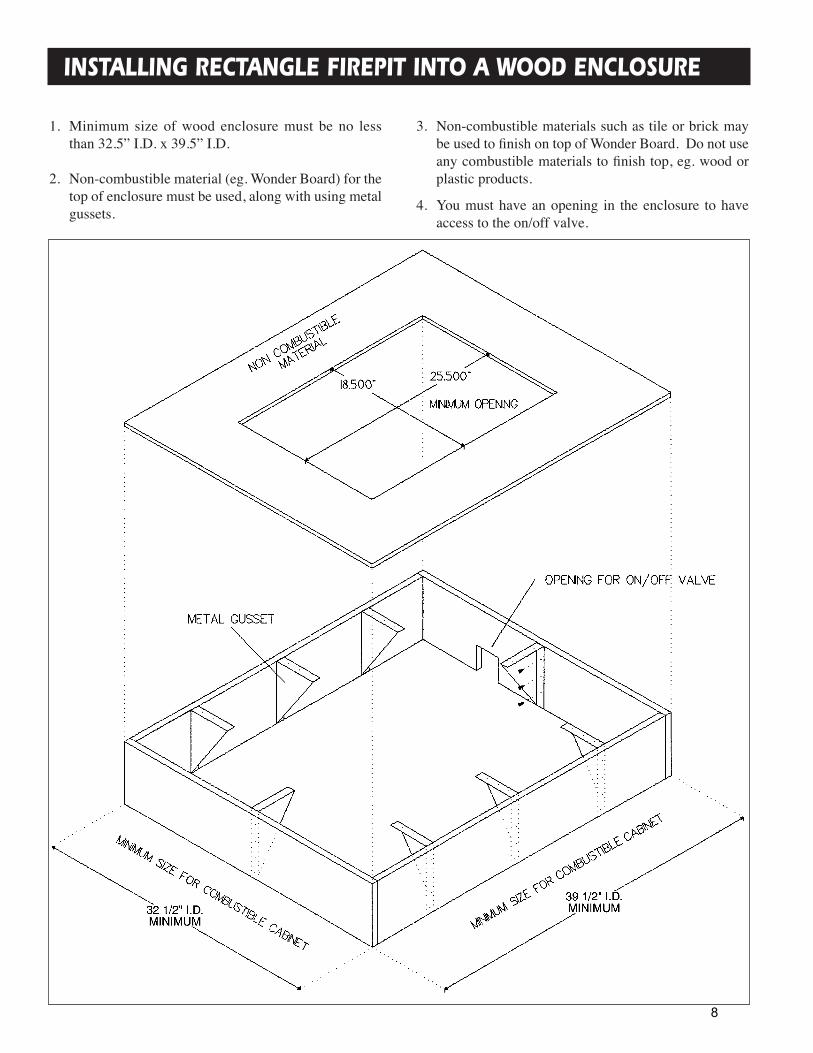
1. Minimum size of wood enclosure must be no lessthan 32.5” I.D. x 39.5” I.D.
2. Non-combustible material (eg. Wonder Board) for thetop of enclosure must be used, along with using metalgussets.
3. Non-combustible materials such as tile or brick maybe used to finish on top of Wonder Board. Do not useany combustible materials to finish top, eg. wood orplastic products.
4. You must have an opening in the enclosure to haveaccess to the on/off valve.
INSTALLING RECTANGLE FIREPIT INTO A WOOD ENCLOSURE
8

1. Using a non-combustible material (eg. Wonder Board)cut two shields, 1 Large 44” x 30 min. and 1 Small 37”x 30” min.
2. Mount six 1” non-combustible spacers to wall, thiswill maintain a 1” air space behind shields Fig:1Ref:F.Non-combustible spacer (eg. Metal Bracket, WonderBoard) should be no wider than 1” and 30” long.
3. Screw non-combustible shield to spacer. Shield mustbe placed 1” below top of firepit Fig:2-Ref:D. Insidecorners of shields should not touch combustible wall.Shield must extend 3” past end of firepit Fig:1-Ref:E.
4. Note: Firepit cabinet or other structures must NOTobstruct wall shield air space on ends, top or bottom.If a cabinet is built around firepit, the end face ofcabinet must not extend past bottom face of clearanceshield by more than 1/2” Fig:2-Ref::D.
INSTALLING WALL CLEARANCE SHIELD
SINGLE CLEARANCE SHIELD
NON-COMBUSTIBLE CORNER CLEARANCE SHIELD
1. Side of unit must be more than 24” from acombustible wall for a single shield to be used, andcan have a distance of no less than 14” to a wall shield.
2. All specifications as in corner installation must beused, including shield must extend a minimum of 3”past sides of firepit Fig:1-Ref:E.
9

Item No. Qty. Part No. Description
7 1 1000-255 Orifice
8 1 125 x 375 Flare
9 1 27FP-104 Orifice Retainer
10 2 8-32 x 1.00 Screw
11 2 10-32 x .500 Screw
12 2 10-32 Locknut
13 2 8-18 x .312 TC Screw
14 2 8-18 x .500 DT Screw
15 2 8-32 Locator Pin
FP2085 FIREPIT ASSEMBLY
Item No. Qty. Part No. Description
1 1 27FP-106 Burner
2 1 20FP-102 Burner Pan
3 1 20FP-101 Frame
4 1 20FP-103 Heat Shield
5 1 27FP-115 Gasket
6 1 27FP-200 Mixing Tube Asm 1 27FP-201
1 4000-208
1 Air Shutter
SS FLEX (27FP-902FF)
#26
#40
10

Item No. Qty. Part No. Description
6 1 125 x 375 Flare
7 1 27FP-104 Orifice Retainer Brkt
8 2 10-32 x .500 Screw
9 2 8-32 Locator Pin
10 2 8-32 x 1.00 Screw
11 2 10-32 Locknut
12 2 8-18 x .312 TC Screw
13 2 8-18 x .500 TC Screw
FP2785 BURNER ASSEMBLY
Item No. Qty. Part No. Description
1 1 27FP-106 Burner
2 1 27FP-105 Burner Pan
3 1 27FP-115 Gasket
4 1 27FP-200 Mixing Tube Asm 1 27FP-201
1 4000-208
1 Air Shutter
5 1 1000-255 Orifice
SS FLEX (27FP-902FF)
#26
#40
11

After setting up your model and hooking up the gas connection, make sure that logs are not broken. Identifythe logs using the pictures below and place logs as indicated, lining up with mounting pegs in logs.
LOG PLACEMENT INSTRUCTIONS
STEP 1 STEP 2
STEP 3
STEP 5
STEP 4
This picture depicts the typical flame pattern of thisburner system.
12
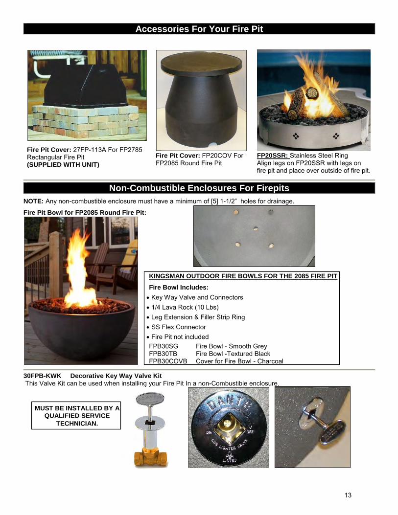
Accessories For Your Fire Pit
Fire Pit Cover: 27FP-113A For FP2785 Rectangular Fire Pit (SUPPLIED WITH UNIT)
Fire Pit Cover: FP20COV For FP2085 Round Fire Pit
FP20SSR: Stainless Steel Ring Align legs on FP20SSR with legs on fire pit and place over outside of fire pit.
Non-Combustible Enclosures For Firepits
NOTE: Any non-combustible enclosure must have a minimum of [5] 1-1/2” holes for drainage.
Fire Pit Bowl for FP2085 Round Fire Pit:
30FPB-KWK Decorative Key Way Valve Kit This Valve Kit can be used when installing your Fire Pit In a non-Combustible enclosure.
KINGSMAN OUTDOOR FIRE BOWLS FOR THE 2085 FIRE PIT
Fire Bowl Includes:
Key Way Valve and Connectors 1/4 Lava Rock (10 Lbs) Leg Extension & Filler Strip Ring SS Flex Connector Fire Pit not included FPB30SG Fire Bowl - Smooth Grey FPB30TB Fire Bowl -Textured Black FPB30COVB Cover for Fire Bowl - Charcoal
MUST BE INSTALLED BY A QUALIFIED SERVICE
TECHNICIAN.
13

30FPB-KWK Decorative Key Way Valve Kit This Valve Kit can be used when installing your Fire Pit in a Non-Combustible Enclosure.
!WARNING
THE INSTALLATION OF THIS KIT MUST ONLY BE UNDERTAKEN BY A QUALIFIED AND CERTIFIED GAS APPLIANCE INSTALLER.
PARTS LIST:
1. 90° Ball Valve c/w Key Way Assembly (27FP-CPBVS)
2. 1/2” MPT x 1/8” FPT Bushing (30FPB-P110DA)
3. Tee 1/8” NPT (30FPB-P107A)
4. Hex Plug 1/8” MPT (30FPB-P118A)
5. Brass Connector 3/8” Tube OD x 1/8” MPT (27FP-P904FF)
6. Valve Mount Bracket (20FP-117)
7. Key Way Installation Tool (20FP-116)
8. SS Flex Connector (27FP-902FF)
9. 3/8” Tube OD Union Coupling (30FPB-P426)
PROCEDURE:
1. Determine a suitable location for Valve if not supplied. NOTE: Mounting surface of Valve should be approximately 1” to 1-1/2” thick if you wish to use supplied Valve Mount Bracket.
2. Drill a 1-1/8” hole (preferably with a core style masonry bit) at this location.
3. Remove Key Way and Valve Mount Bracket from Valve Body.
4. Remove existing valve from Fire Pit assembly. 5. Connect Key Way Valve Body to Fire Pit Connector. 6. Place Key Way into 1-1/8” hole. 7. Place Valve Mount Bracket onto Valve. 8. Manually start threads of Key Way onto Valve body. 9. Using supplied tool, tighten Key Way onto Valve. 10. Proceed with installation of Fire Pit and Fuel Supply.
To Fire Pit
Fuel Supply (LP Hose Shown)
1 (Key) 1 (Key Way)
1 (Valve Body)
2
3
4
5
6 7
To Fire Pit
Remove Existing Valve on Fire Pit
8
9
! WARNING
Always check for gas leaks with a soap and water solution. DO NOT USE OPEN FLAME FOR LEAK
TESTING.
USE PIPE THREAD SEALANT
14

Kingsman Outdoor Fire Pit Media Section
REQUIRED AMOUNT OF MEDIA
ACCESSORY ITEM FP2785 Rectangular
Fire Pit FP2085 Round Fire
Pit Only FP2085 Round Fire Pit With Fire Bowl
ROCKS
*MLR1410 - 1/4" Lava Rock 10 LBS
10 LBS (1 BAG)
10 LBS (1 BAG)
20 LBS *(2 BAGS)
*Fire Bowl Includes: ¼” Lava Rock – 10LBS
-MQ DEALERS ONLY-
MQSTONE - Decorative Stones
1 BAG 1 BAG 2 BAGS
NOTE: The MQSTONE requires a Glass or Lava Rock Base.
GLASS
MQG5W -1/2” White Glass 5LBS
20LBS (4 BAGS)
20LBS (4 BAGS)
30-35LBS (6-7 BAGS)
MQG5C - 1/2”Bronze Glass 5LBS
20LBS (4 BAGS)
20LBS (4 BAGS)
30-35LBS (6-7 BAGS)
MQG5A - 1/2”Cobalt Blue Glass 5LBS
20LBS (4 BAGS)
20LBS (4 BAGS)
30-35LBS (6-7 BAGS)
MQG5B -1/2” Black Glass 5LBS
20LBS (4 BAGS)
20LBS (4 BAGS)
30-35LBS (6-7 BAGS)
MQG10C - 1/4" Reflective Bronze Glass 10 LBS
20LBS (2 BAGS)
20LBS (2 BAGS)
30-35LBS (3-4 BAGS)
MQG10B - 1/4" Black Glass 10 LBS
20LBS (2 BAGS)
20LBS (2 BAGS)
30-35LBS (3-4 BAGS)
Media Examples Shown Below.
FP2085 Without Media
¼” Lava Rock (1 Bag – 10LBS)
MEDIA REQUIREMENTS OPTIONS: (When not using LOGC85 Log Set)
20 LBS of Glass Required for Fire Pits, if using the Fire Bowl add an additional 10-15LBS of Glass. One bag of MQSTONE may be used for the Fire Pit, if using the Fire Bowl an additional bag may be used. One [10LB] bag of 1/4" Lava Rock is required for the Fire Pit and an additional [10LB] bag for the Fire Bowl (2-10LB bags of 1/4” Lava Rock are supplied with Fire Bowl) may be used to fill the entire Bowl with the same material.
15

¼” Lava Rock & ¾” Lava Rock (Supplied with Fire Pit).
(1/4” Lava Rock is used as Base.)
¼” Reflective Bronze Glass - (20LBS)
MQSTONE with ¼” Lava Rock Base – (10LBS)
MQSTONE with ¼” Bronze Glass Base – (20LBS)
NOTE: MQSTONE Requires a Glass or Lava Rock Base.
16

1. The appliance should be inspected before initial useand inspected and cleaned at least annually by aqualified field service person.
2. Tampering is DANGEROUS and voids allwarranties. Any component that is found to be faulty,must be replaced with an approved component.
3. To obtain proper operation, it is imperative that theburner flame characteristics are steady, not lifting orfloating. Check the burner flame patterns with Log Placement Instructions Section.
OPERATING INSTRUCTIONS
MAINTENANCE INSTRUCTIONS
4. Periodically remove the logs and examine the burner.If dirty, clean with a soft brush. Also examine thearea around the burner air shutter. Any dirt or lint inthis area should be removed. This will ensure longlife and trouble free operation. Re-install the logs asshown in the log placement instructions. When theappliance is put back in service, check the burnerflame patterns with Log Placement Instructions Section.
5. Periodically check the hose connecting the LP-gascylinder to ensure it is not damaged in any way.
U.L. Listed gas fireplaces are tested and approved forelevations from 0 to 4,500 feet in Canada and U.S.A.
When installing this fireplace at an elevation above 4,500feet (in Canada), check with local authorities.
HIGH ELEVATION INSTALLATION
Consult your local gas utility for assistance indetermining the proper orifice for your location.
Upon completing the gas line connection, a small amountof air will be in the lines. When first lighting the burner,it will take a few minutes for the lines to purgethemselves of this air. Once the purging is complete, theburner will light and operate as indicated in theinstruction manual. Subsequent lighting of the appliancewill not require such purging.
WARNING: Read and follow the Safety and LightingInstructions page in this manual and on labels on theappliance. IF YOU DO NOT FOLLOW THESEINSTRUCTIONS PRECISELY, A FIRE OREXPLOSION MAY RESULT AND YOU MAY BESERIOUSLY INJURED!
17

SAFETY INFORMATION AND LIGHTING INSTRUCTIONS
1. Turn the on/off valve to the off position at the unitfor natural gas unit. For LP unit, turn the on/offvalve to the off position at the unit and then turn thevalve on the LP tank to the off position clockwise.
2. Replace the top cover.
TO TURN OFF GAS APPLIANCE
5. If the burner does not light before the match goes out, immediately turn the gas to off.
6. Wait at least five (5) minutes to clear out any gas.If you have unsuccessfully tried to light the burner, wait longer. Then smell for gas, including near thefloor. If you smell gas, STOP! Follow “B” in thesafety information above. If you don’t smell gas,repeat step 4.
1. STOP! Read the safety information above.
2. Remove the top cover.
3. Find the manual gas control valve.
4. Place a burning match on top of burner in themiddle where ports are present. DO NOT HOLDTHE MATCH IN HAND. For Natural Gas unitturn on the on/off valve slowly at the unit. For LPunit turn the valve on the LP tank counter-clockwise all the way and then turn on the on/offvalve slowly at the unit.
• If you cannot reach your gas supplier, call the firedepartment.
C. Use only your hand to turn the gas control knob orvalve. Never use tools. If the valve will not turn byhand, don’t try to repair it, call a qualified servicetechnician. Force or attempted repair may result ina fire or explosion.
D. Do not use this appliance if any part has beenunderwater. Immediately call a qualified servicetechnician to inspect the appliance, and to replaceany part which has been underwater.
A. This appliance must be lit by hand. When lighting,follow these instructions exactly.
B. Before LIGHTING, smell all around the appliancearea for gas. Be sure to smell next to the floor, because some gas is heavier than air and will settleon the floor.
WHAT TO DO IF YOU SMELL GAS• Do not try to light any appliance.• Do not touch any electric switch; do not use any phone
in your building.• Immediately call your gas supplier from a neighboursphone. Follow the gas suppliers instructions.
WARNING: If you do not follow these instructions exactly, a fire or explosion may resultcausing property damage, personal injury or loss of life.
FOR YOUR SAFETY READ BEFORE LIGHTING
LIGHTING INSTRUCTIONS
18

FP2085/FP2785 Parts List
KINGSMAN FIRE PITS: Listed for Canada and USA
NUMBER DESCRIPTION FP2085N Round 20” Diameter - 65,000 BTU - Natural Gas c/w 10LBS ¾” Lava Rock FP2085LP Round 20” Diameter - 65,000 BTU - Liquid Propane c/w 10LBS ¾” Lava Rock FP2785N Rectangular 27” x 20” - 65,000 BTU - Natural Gas c/w Cover & 10LBS ¾” Lava Rock FP2785LP Rectangular 27” x 20” - 65,000 BTU - Liquid Propane c/w Cover& 10LBS ¾” Lava Rock
LOG SET
LOGC85 Log Set - Four piece Cast oak MEDIA OPTIONS MLR1410 Media - 1/4" Lava Rock 10 lbs MEDIA OPTIONS – MQ DEALER ONLY
MQSTONE Decorative Stones MQG5W Decorative Glass 1/2” White MQG5A Decorative Ember Glass 1/2” Cobalt Blue MQG5C Decorative Ember Glass - 1/2” Bronze MQG5B Decorative Ember Glass - 1/2” Black MQG10C Media - 1/4" Reflective Bronze Glass 10 lbs MQG10B Media - 1/4" Black Glass 10 lbs FIRE PIT ACCESSORIES OPTIONS
27FP-113A Cover for Rectangular Fire Pit (SUPPLIED WITH UNIT) FP20COV Cover for Round Fire Pit FP20SSR Stainless Steel Ring (Fits FP2085N, FP2085LP) 30FPB-KWK Decorative Key Way Valve and Connectors
MUST BE INSTALLED BY A QUALIFIED SERVICE TECHNICIAN OUTDOOR FIRE BOWLS FOR THE 2085 FIRE PIT Fire Bowl Includes Key Way Valve and Connectors, 1/4 Lava Rock (10 Lbs), Leg Extension, Filler Strip Ring and SS Flex Connector. Fire Pit not included.
FPB30TB Fire Bowl - Textured Black FPB30SG Fire Bowl - Smooth Grey FPB30COVB Cover for Fire Bowl - Charcoal FPB30COVG Cover for Fire Bowl - Grey KINGSMAN FIRE PITS REPLACEMENT PARTS
27FP-900FF LP Reg & 5ft Hose (I4T60GRQC) 27FP-901FF Ball Valve with Manometer (BVTM5042-6)
27FP-902FF SS Gas Connector 16” (ACS-375-16) 27FP-P904FF Brass Connector 48-6A
27FP-P486D Connector 3/8 to ½ 48-6D
1000-255 Brass Orifice 27FP-115 Gasket
REPLACEMENT PARTS FOR MANOMETER SUB-ASSEMBLY OF 30FPB-KWK KEY WAY VALVE KIT 30FPB-P107A Tee 1/8 107-A @ 1.280
30FPB-P110DA Bushing ½-1/8 110-DA @ .72
30FPB-P118A Plug 118-A @ .22
19

Kingsman Fireplaces Gas Fire Pit – Limited Warranty Save this certificate. It gives you specific legal rights, and you may also have other rights which may vary from state to state. In the event your unit needs servicing contact your dealer or contractor who installed or service your unit. When requesting service, please have the model and serial number from each unit readily available. If your dealer needs assistance, the distributor is available for support and we, in turn support the distributor's efforts.
Fill in the installation date and model and serial numbers of the unit in the space provided below and retain this limited warranty for your files.
GENERAL TERMS This limited warranty applies only while the unit remains at the site of the original installation and only if the unit is installed inside the continental United States, Alaska, Hawaii and Canada. The warranty applies only if the unit is installed and operated in accordance with the printed instructions and in compliance with applicable installation, building codes and good trade practices.
During the first year after installation, we will provide a replacement for any component part of your unit found to be defective in materials or workmanship. The part to be replaced must be returned to our distributor in exchange for the replacement part.
In lieu of providing a replacement part, we may, at our option, provide the distributor's component purchase price from us or a credit equal to the distributor’s component purchase price from us toward the purchase of any new unit which we distribute. If a credit is given in lieu of a replacement part, the rating plate from the unit being replace must be submitted on a warranty claim and the unit being replaced must be made available to our distributor for disposition.
In establishing the date of installation for any purpose including determination of the starting date for the term of this limited warranty, reasonable proof of the original installation date must be presented*, otherwise the effective date will be based upon the date of manufacture plus thirty (30) days.
Any labor, material, freight and/or handling charges associated with any repair or replacement pursuant to this limited warranty will be your responsibility. In this warranty the word "installation" means original installation.
We will not be responsible for and you the user will pay for: (a) damages caused by accident, abuse, negligence, misuse, riot. fire, flood, or Acts of God (b) damages caused by operating the unit where there is a corrosive atmosphere containing chlorine, fluorine, or any other damaging chemicals (other than in a normal residential environment) (c) damages caused by any unauthorized alteration or repair of the unit affecting its stability or performance (d) damages caused by improper matching or application of the unit or the unit's components (e) damages caused by failing to provide proper maintenance and service to the unit (f) any expenses incurred for erecting disconnecting or dismantling the unit (g) parts or supplies used in connection with service or maintenance (h) damage repairs, inoperation or inefficiency resulting from faulty installation or application (i) electricity or fuel costs or any increase in electricity or fuel cost whatsoever including additional or unusual use of supplemental electric heat.
We shall not be liable for any incidental, consequential, or special damages or expenses in connection with any use or failure of this unit. We have not made and do not make any representation or warranty of fitness for a particular use or purpose and there is no implied condition of fitness for a particular use or purpose. We make no express warranties except as stated in this limited warranty. No one is authorized to change this limited warranty or to create for us any other obligation or liability in connections with this unit. Any implied warranties shall last for one year after the original installation. Some states and provinces do not allow the exclusion or limitation of incidental or consequential damages or do not allow limitations on how long an implied Warranty or condition lasts so the above limitations or exclusions may not apply to you. The provisions of this limited warranty are in additions to and not a modification of or subtraction from an statutory warranties and other rights and remedies provided by law.
Model No.: Serial No.:
Date Installed:
*You must retain the original records that can establish the installation date of your unit.
20