OSP LTE Wireless HLD_summary
62
Orange Spain LTE Project High Level Design Issue 1.0 Date 2013-17-05 HUAWEI TECHNOLOGIES CO., LTD.
-
Upload
joao-lopes -
Category
Documents
-
view
353 -
download
18
Transcript of OSP LTE Wireless HLD_summary

Orange Spain LTE Project High Level Design
Issue 1.0
Date 2013-17-05
HUAWEI TECHNOLOGIES CO., LTD.

1st version Erro! Nome desconhecido de propriedade de documento (May 2013)
Huawei Proprietary and Confidential Copyright © Huawei Technologies Co., Ltd
i
Copyright © Huawei Technologies Co., Ltd. 2011. All rights reserved.
No part of this document may be reproduced or transmitted in any form or by any means without prior written consent of Huawei Technologies Co., Ltd.
Trademarks and Permissions
and other Huawei trademarks are trademarks of Huawei Technologies Co., Ltd.
All other trademarks and trade names mentioned in this document are the property of their respective holders.
Notice
The purchased products, services and features are stipulated by the contract made between Huawei and the customer. All or part of the products, services and features described in this document may not be within the purchase scope or the usage scope. Unless otherwise specified in the contract, all statements, information, and recommendations in this document are provided "AS IS" without warranties, guarantees or representations of any kind, either express or implied.
The information in this document is subject to change without notice. Every effort has been made in the preparation of this document to ensure accuracy of the contents, but all statements, information, and recommendations in this document do not constitute the warranty of any kind, express or implied.
Huawei Technologies Co., Ltd.
Address: Huawei Industrial Base
Bantian, Longgang
Shenzhen 518129
People's Republic of China
Website: http://www.huawei.com
Email: [email protected]
Version History
1st version Erro! Nome desconhecido de propriedade de documento (May 2013)
Huawei Proprietary and Confidential Copyright © Huawei Technologies Co., Ltd
ii
Version History
Version Date Changes Author
Draft 2013-05-04 Draft version Jorge Sevilla
0.1 2013-19-04 First version to review Jorge Sevilla
0.2 2013-29-04 Jorge Sevilla
1.0 2013-17-05 New LTE2600MHz configuration / RNO/RNP comments added /eNodeB in pool topology added
Jorge Sevilla
Contents
Contents
1 Introduction.................................................................................................................................... 9 1.1 Scope ................................................................................................................................................................ 9
1.2 Technical proposal ............................................................................................................................................ 9
2 LTE System Architecture ........................................................................................................... 10 2.1 General ........................................................................................................................................................... 10
2.2 OSP TX topology ........................................................................................................................................... 11
3 Hardware Modeling ................................................................................................................... 13 3.1 Macro solution ............................................................................................................................................... 13
3.1.1 BTS3900 description ................................................................................................................................... 13
3.1.1 BTS3900A description ................................................................................................................................ 16
3.2 Distributed Solution ....................................................................................................................................... 21
3.2.1 BBU3900 slot design .................................................................................................................................. 21
3.2.2 Board introduction ...................................................................................................................................... 22
3.2.3 Boards specifically used in Valencia Area (LTE2600) ................................................................................ 26
3.2.4 LTE 2600 MHz scenario ............................................................................................................................. 27
3.2.5 LTE 1800 MHz scenario ............................................................................................................................. 28
3.3 Radio Frequency Units ................................................................................................................................... 28
3.3.1 LTE 2600 MHz scenario ............................................................................................................................. 28
3.3.2 LTE 1800 MHz scenario ............................................................................................................................. 29
3.3.3 CPRI cabling design .................................................................................................................................... 29
3.4 Antenna solution ............................................................................................................................................. 30
3.4.1 Radiating System Guidelines ...................................................................................................................... 31
3.4.2 Antenna Decision path ................................................................................................................................ 31
3.4.3 Antenna model selection ............................................................................................................................. 32
3.4.4 TMA guidelines ........................................................................................................................................... 32
3.5 Site scenario overview ................................................................................................................................... 32
3.5.1 Indoor DBS single band LTE2600 .............................................................................................................. 33
3.5.2 Indoor macro single band LTE2600 ............................................................................................................ 33
3.5.3 Outdoor DBS single band LTE2600 ............................................................................................................ 34
3.5.4 Outdoor macro single band LTE2600 ......................................................................................................... 34
3.5.5 Indoor macro single band LTE1800 with 3 spare slots ............................................................................... 35
3.5.6 Indoor macro single band LTE1800 without spare slots ............................................................................. 36
Contents
1st version Erro! Nome desconhecido de propriedade de documento (May 2013)
Huawei Proprietary and Confidential Copyright © Huawei Technologies Co., Ltd
iv
3.5.7 Outdoor macro single band LTE1800 with 3 spare slots ............................................................................. 37
3.5.8 Outdoor macro single band LTE1800 without spare slots ........................................................................... 38
3.5.9 Indoor DBS single band LTE1800 .............................................................................................................. 39
3.5.10 Outdoor DBS single band LTE1800 .......................................................................................................... 39
4 Software ........................................................................................................................................ 41 4.1 Software versions ........................................................................................................................................... 41
4.2 Feature List..................................................................................................................................................... 42
4.2.1 LTE FDD eRAN3.0 feature list ................................................................................................................... 42
4.2.2 CS fallback strategy .................................................................................................................................... 42
4.2.3 eNodeB in pool strategy .............................................................................................................................. 42
4.3 License ........................................................................................................................................................... 43
5 Radio network planning and optimization ........................................................................... 44 5.1 eNodeB Naming and Numbering rule design ................................................................................................ 44
5.1.1 eUTRAN Cell ID and eNodeB ID .............................................................................................................. 44
5.2 eNodeB naming criteria ................................................................................................................................. 46
6 O&M Topology Structure ......................................................................................................... 47
7 Interface IP design and traffic flows ....................................................................................... 49 7.1 IP addressing scheme and VLAN proposal .................................................................................................... 49
7.1.1 Gerneral IP addressing scheme ................................................................................................................... 49
7.1.2 FTTN scenario ............................................................................................................................................ 49
7.1.3 PMW scenario ............................................................................................................................................. 50
7.2 Traffic flows ................................................................................................................................................... 51
7.2.1 S1 interface traffic flow ............................................................................................................................... 51
7.2.2 O&M traffic flow ........................................................................................................................................ 52
7.2.3 X2 interface traffic flow .............................................................................................................................. 53
8 QoS ................................................................................................................................................. 54 8.1 QoS Proposal .................................................................................................................................................. 54
8.1.1 QoS in LTE System ..................................................................................................................................... 54
8.1.2 QoS in IP Networks ..................................................................................................................................... 55
8.1.3 QoS Mapping .............................................................................................................................................. 55
8.1.4 Capacity and QoS ........................................................................................................................................ 57
9 System Clock Design.................................................................................................................. 58 9.1 Synchronization requirements ........................................................................................................................ 58
9.2 Synchronous Ethernet .................................................................................................................................... 59
10 MTU ............................................................................................................................................. 60 10.1 MTU requirements and jumbo frame support .............................................................................................. 60
11 Annex ........................................................................................................................................... 61

List of Figures
1st version Erro! Nome desconhecido de propriedade de documento (May 2013)
Huawei Proprietary and Confidential Copyright © Huawei Technologies Co., Ltd
v
List of Figures
Figure 1: LTE system architecture ....................................................................................................................... 10
Figure 2: 3GPP Rel. 8 Network Architecture ....................................................................................................... 11
Figure 3: Target UMTS+LTE architecture ........................................................................................................... 11
Figure 4: General transmission network architecture ........................................................................................... 12
Figure 5: Different eNodeB TX connectivity scenarios ....................................................................................... 12
Figure 6 BTS3900 cabinet.................................................................................................................................... 13
Figure 7 DCDU-12A/DCDU-12B. (1) DC Input terminals; (2) Fuse blocks; (3) DC output terminals ............... 15
Figure 8 APM30H configuration .......................................................................................................................... 16
Figure 9 RFC configuration ................................................................................................................................. 18
Figure 10 TMC11H configuration ........................................................................................................................ 19
Figure 11 IBBS200D configuration ..................................................................................................................... 20
Figure 12 UMPT board ........................................................................................................................................ 22
Figure 13 LBBPd1 board ..................................................................................................................................... 23
Figure 14 UPEUc board. (1) BBU power switch; (2) 3V3 connector .................................................................. 24
Figure 15 UEIU board .......................................................................................................................................... 24
Figure 16 UCIU board ......................................................................................................................................... 25
Figure 17 FANc board .......................................................................................................................................... 26
Figure 18 LMPT board ......................................................................................................................................... 27
Figure 19 LBBPc board ....................................................................................................................................... 27
Figure 20: BBU picture (left) and default LTE 2600 MHz configuration (right) ................................................. 27
Figure 21: Common BBU configuration in LTE 1800 MHz scenario .................................................................. 28
Figure 22: CPRI cabling desing in DBS3900 scenario ........................................................................................ 29
Figure 23: CPRI cabling desing in BTS3900 scenario ......................................................................................... 30
Figure 24: Indoor DBS single band LTE2600 scenario ........................................................................................ 33
Figure 25: Indoor macro single band LTE2600 scenario ..................................................................................... 34
Figure 26: Outdoor DBS single band LTE2600 scenario ..................................................................................... 34
List of Figures
1st version Erro! Nome desconhecido de propriedade de documento (May 2013)
Huawei Proprietary and Confidential Copyright © Huawei Technologies Co., Ltd
vi
Figure 27: Outdoor macro single band LTE2600 scenario ................................................................................... 35
Figure 28: Indoor macro single band LTE1800 scenario with 3 spare slots ......................................................... 36
Figure 29: Indoor macro single band LTE1800 scenario without spare slots ....................................................... 37
Figure 30: Outdoor macro single band LTE1800 with 3 spare slots .................................................................... 38
Figure 31: Outdoor macro single band LTE1800 without spare slots .................................................................. 38
Figure 32: Indoor DBS single band LTE1800 ...................................................................................................... 39
Figure 33: Outdoor DBS single band LTE1800 ................................................................................................... 40
Figure 34: Cell Identifier coding .......................................................................................................................... 44
Figure 35 O&M network topology ....................................................................................................................... 47
Figure 36 Network Management System ............................................................................................................. 48
Figure 37 NMS integration in OSP OSS .............................................................................................................. 48
Figure 38 Transmission network topology in FTTN scenarios. Note that VLAN A will be used for S1/X2 traffic data, whereas VLAN B will be applied to OMCH scenario. A unique VLAN A and VLAN B will be used per each eNodeB................................................................................................................................................................. 50
Figure 39 Transmission network topology in PMW scenarios. Note that VLAN A will be used for S1/X2 traffic data, whereas VLAN B will be applied to OMCH scenario. Both VLAN A and VLAN B will be shared between all the eNodeBs under the same POC. ................................................................................................................. 51
Figure 40 S1 interface traffic flow ....................................................................................................................... 52
Figure 41 O&M traffic flow ................................................................................................................................. 53
Figure 42 X2 interface traffic flow ....................................................................................................................... 53
Figure 43 Ethernet Synchronization ..................................................................................................................... 59
Figure 44 LTE protocol stack ............................................................................................................................... 60
List of Tables
List of Tables
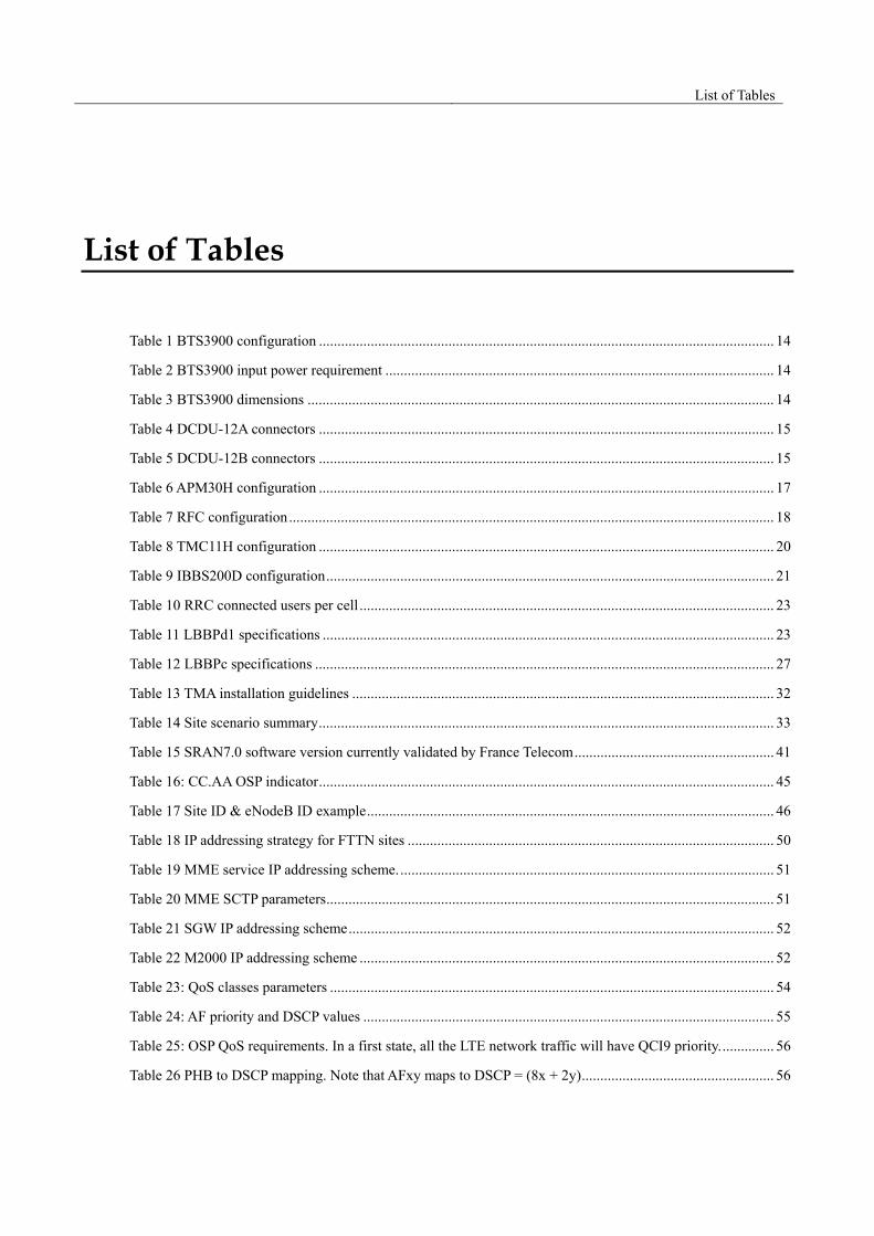
Table 1 BTS3900 configuration ........................................................................................................................... 14
Table 2 BTS3900 input power requirement ......................................................................................................... 14
Table 3 BTS3900 dimensions .............................................................................................................................. 14
Table 4 DCDU-12A connectors ........................................................................................................................... 15
Table 5 DCDU-12B connectors ........................................................................................................................... 15
Table 6 APM30H configuration ........................................................................................................................... 17
Table 7 RFC configuration ................................................................................................................................... 18
Table 8 TMC11H configuration ........................................................................................................................... 20
Table 9 IBBS200D configuration ......................................................................................................................... 21
Table 10 RRC connected users per cell ................................................................................................................ 23
Table 11 LBBPd1 specifications .......................................................................................................................... 23
Table 12 LBBPc specifications ............................................................................................................................ 27
Table 13 TMA installation guidelines .................................................................................................................. 32
Table 14 Site scenario summary ........................................................................................................................... 33
Table 15 SRAN7.0 software version currently validated by France Telecom ...................................................... 41
Table 16: CC.AA OSP indicator ........................................................................................................................... 45
Table 17 Site ID & eNodeB ID example .............................................................................................................. 46
Table 18 IP addressing strategy for FTTN sites ................................................................................................... 50
Table 19 MME service IP addressing scheme. ..................................................................................................... 51
Table 20 MME SCTP parameters ......................................................................................................................... 51
Table 21 SGW IP addressing scheme ................................................................................................................... 52
Table 22 M2000 IP addressing scheme ................................................................................................................ 52
Table 23: QoS classes parameters ........................................................................................................................ 54
Table 24: AF priority and DSCP values ............................................................................................................... 55
Table 25: OSP QoS requirements. In a first state, all the LTE network traffic will have QCI9 priority. .............. 56
Table 26 PHB to DSCP mapping. Note that AFxy maps to DSCP = (8x + 2y) .................................................... 56

OSP LTE Wireless HLD
1st version Erro! Nome desconhecido de propriedade de documento (May 2013)
Huawei Proprietary and Confidential Copyright © Huawei Technologies Co., Ltd
8
Table 27: Huawei’s Proposal on QCI-to-DSCP-to-VLAN priority mapping ....................................................... 57
Table 28: QoS requirements for S1/X2 interfaces ................................................................................................ 57
OSP LTE Wireless HLD
1st version Erro! Nome desconhecido de propriedade de documento (May 2013)
Huawei Proprietary and Confidential Copyright © Huawei Technologies Co., Ltd
9
1 Introduction
1.1 Scope Huawei Technologies is collaborating with Orange Spain in the deployment of a fully-operational LTE FDD network in OSP South region, using either 1800 MHz or 2600 MHz frequency band.
This document intends to present Huawei’s high level technical proposal for this project, concerning the evolved Radio Access Network (eRAN) and Operating Support System (OSS).
For the transmission network, Orange’s network will be used since LTE sites will be deployed on current Orange 3G/2G locations. Huawei will provide recommendations for the proper dimensioning and configuration of the transmission network.
EPC architecture is out of the scope of Huawei eRAN design.
1.2 Technical proposal The attached technical proposal was created to summarize the whole scope of OSP LTE project in response to OSP RAN LTE RFP 2012 issued by Orange Spain. After the final resolution, this document should only be used as a reference to perform a smooth upgrade of current GSM/UMTS network into a three-technology GSM/UMTS/LTE network in South area.

OSP LTE Wireless HLD
1st version Erro! Nome desconhecido de propriedade de documento (May 2013)
Huawei Proprietary and Confidential Copyright © Huawei Technologies Co., Ltd
10
2 LTE System Architecture
2.1 General The LTE System Architecture can be seen in Figure 1. User Equipment (UE) accesses the LTE system through
the evolved Radio Access Network (eRAN), which consists of one single network element, the eNodeB. It provides radio access to the LTE network and centralizes all radio-related features, such as Radio Resource Management (RRM) or interface management.
ENodeB to EPC connection is conveyed through S1 interface which, in turn, is divided into S1-MME interface for control plane and S1-U interface for user plane. The X2 interface inter-connects eNodeB in order to exchange signaling for interference and load management and to perform handovers faster.
Figure 1: LTE system architecture
Figure 2 provides an overview of the evolution of the 3GPP 2G and 3G Network architecture by adding LTE network elements:

OSP LTE Wireless HLD
1st version Erro! Nome desconhecido de propriedade de documento (May 2013)
Huawei Proprietary and Confidential Copyright © Huawei Technologies Co., Ltd
11
Figure 2: 3GPP Rel. 8 Network Architecture
How the existing BSS and LTE network will coexist is described in the figure below:
Figure 3: Target UMTS+LTE architecture
2.2 OSP TX topology The enclosed document explains the solution implemented to transport the eNodeB traffic through the evolved packet core (EPC) isolating LTE traffic and describes the different TX topology scenarios considered in OSP network. Besides it analyses the possible impact in the scenarios where the eNodeB coexists with the Orange City LTE (Trial solution), 2G/3G services sharing the same transmission media between CSG / RTN and POP, sharing current 3G FTTN project mobile backhaul and sharing current 2G and 3G PMW infrastructure.
SG i
S 12
S3S1- M M E
PC R F
G x
S6a
H S S
O p e ra to r 's IP S e rvic e s
(e . g . IM S , P S S e tc. )
R x
S 10
U E
SG S N
LTE -U u
E -U T R A N
M M E
S11
S5S e rv ingG a tew ay
P D NG a te w a y
S 1-U
S 4
U TR A N
GE R A N
New UGW
New HSS
New USN
EUTRAN
New PCRF
BTS/NB LTE eNB
RNC
EPC
Iu
S1 Iub
X2
Transmission Network
OSP 2G/3G CN
Internet
A, B
LTE OSS Server
LTE OSS connections
BTS/NB
BTS/NB LTE eNB
UMTS interfaces
Selected site Selected site
LTE interfaces
M2000 Server
OSP LTE Wireless HLD
1st version Erro! Nome desconhecido de propriedade de documento (May 2013)
Huawei Proprietary and Confidential Copyright © Huawei Technologies Co., Ltd
12
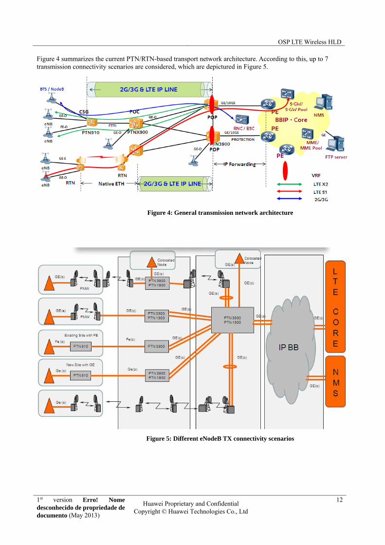
Figure 4 summarizes the current PTN/RTN-based transport network architecture. According to this, up to 7 transmission connectivity scenarios are considered, which are depictured in Figure 5.
Figure 4: General transmission network architecture
Figure 5: Different eNodeB TX connectivity scenarios

OSP LTE Wireless HLD
1st version Erro! Nome desconhecido de propriedade de documento (May 2013)
Huawei Proprietary and Confidential Copyright © Huawei Technologies Co., Ltd
13
3 Hardware Modeling
In this chapter, the Radio solution for Orange Spain LTE project is presented. The different hardware types to be used for the deployment of LTE solution belong to 3900-series base station and are listed here:
BTS3900: Indoor Cabinet Base Station
BTS3900A: Outdoor Cabinet Base Station
DBS3900: Distributed Base Station
All these models consist of 3 basic types of modules: Base-band Unit (BBU), Radio Frequency Units (RFUs) and Remote Radio Units (RRUs).
3.1 Macro solution
3.1.1 BTS3900 description
A BTS3900 cabinet (-48 V DC) consists of the RFUs, fan assembly, BBU3900, DCDU-12A, and 3 U space for customer equipment. The BTS3900 DC cabinet can provide power to the transmission equipment installed in 3 U space. The customer equipment must work at an environmental temperature of 55oC or higher. When the base station is configured with both RFUs and RRUs, the BBU3900 and DCDU-12B are configured in the 3 U space reserved for customer equipment.
Figure 6 BTS3900 cabinet

OSP LTE Wireless HLD
1st version Erro! Nome desconhecido de propriedade de documento (May 2013)
Huawei Proprietary and Confidential Copyright © Huawei Technologies Co., Ltd
14
No. Module Optional/Mandatory
Max. Quantity
configured in a Single Cabinet
Remarks
1 RFU Mandatory 6
The RFU performs the following functions: modulation and demodulation of baseband signals and RF signals, data processing as well as signal combination and division.
2 Filler panel Optional - To ensure proper ventilation of the cabinet, install a filler panel in each vacant slot in the RFU subrack.
3 Fan
assembly Mandatory 1
The fan assembly dissipates heat from the cabinet. The fan assembly is configured with the fan monitoring unit type EA (FMUEA), which monitors the fans and reports alarms.
4 Filler panel Mandatory 1 Air intake vent of the cabinet
5 BBU3900 Mandatory 1 The BBU3900 processes the baseband signals and enables interaction between the base station and base station controller.
6 DCDU-12A Mandatory 1 The DCDU-12A provides DC power to all components in the cabinet.
7 BBU3900 Optional 1 When the base station is configured with both RFUs and RRUs, an additional BBU3900 is configured.
8 DCDU-12B Optional 1 When the base station is configured with both RFUs and RRUs, the DCDU-12B is configured to feed DC power into the RRUs.
Table 1 BTS3900 configuration
Engineering specifications
A BTS3900 cabinet supports -48 V DC, 220 V AC single-phase and 220 V AC three-phase power inputs, as listed in Table 2.
Input Power Voltage Range
‐48V DC ‐38.4V DC to ‐57V DC
220V AC (single‐phase) 176V AC to 290V AC
220V AC (three‐phase) 176V AC to 290V AC
Table 2 BTS3900 input power requirement
Input Power Voltage Range
Cabinet dimensions (HxWxD) 900 mm x 600 mm x 450 mm
Base: 40 mm x 600 mm x 420 mm
Weight Cabinet in full configuration ≤ 120 Kg
Table 3 BTS3900 dimensions
OSP LTE Wireless HLD
1st version Erro! Nome desconhecido de propriedade de documento (May 2013)
Huawei Proprietary and Confidential Copyright © Huawei Technologies Co., Ltd
15
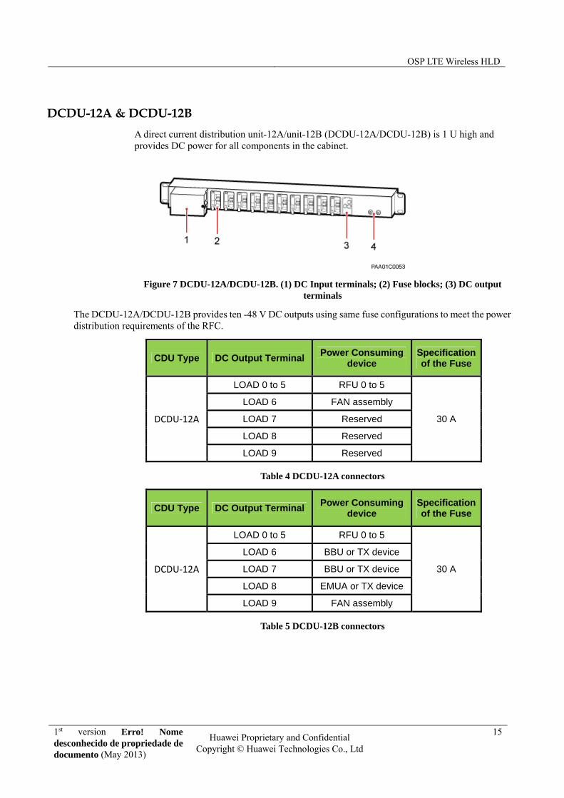
DCDU-12A & DCDU-12B
A direct current distribution unit-12A/unit-12B (DCDU-12A/DCDU-12B) is 1 U high and provides DC power for all components in the cabinet.
Figure 7 DCDU-12A/DCDU-12B. (1) DC Input terminals; (2) Fuse blocks; (3) DC output terminals
The DCDU-12A/DCDU-12B provides ten -48 V DC outputs using same fuse configurations to meet the power distribution requirements of the RFC.
CDU Type DC Output Terminal Power Consuming
device Specification of the Fuse
DCDU‐12A
LOAD 0 to 5 RFU 0 to 5
30 A
LOAD 6 FAN assembly
LOAD 7 Reserved
LOAD 8 Reserved
LOAD 9 Reserved
Table 4 DCDU-12A connectors
CDU Type DC Output Terminal Power Consuming
device Specification of the Fuse
DCDU‐12A
LOAD 0 to 5 RFU 0 to 5
30 A
LOAD 6 BBU or TX device
LOAD 7 BBU or TX device
LOAD 8 EMUA or TX device
LOAD 9 FAN assembly
Table 5 DCDU-12B connectors

OSP LTE Wireless HLD
1st version Erro! Nome desconhecido de propriedade de documento (May 2013)
Huawei Proprietary and Confidential Copyright © Huawei Technologies Co., Ltd
16
3.1.1 BTS3900A description
To meet requirements in different outdoor environments, Huawei provides various cabinets with different functions for the separated macro base station. The advanced power module with heat exchanger (APM30H) and radio frequency cabinet (RFC) provide space, power, heat dissipation, and surge protection for the BBU3900 and RFUs. The integrated battery backup system with direct ventilation (IBBS200D) supplies backup power to the base station. The transmission cabinet of 11 U high with heat exchanger (TMC11H) provides space for customer equipment and will be used if required.
APM30H Configurations
The APM30H houses the BBU3900 and also provides 5 U installation space for customer equipment such as the EMUA, AC heater, and service outlet unit (SOU), which are optional.
Figure 8 APM30H configuration
No. Module Optional/Mandatory
Max. Quantity
configured in a Single Cabinet
Remarks
1 Outer air
circulation component
Mandatory 1
The outer air circulation component includes the heat exchanger core and fans.
The heat exchanger core promotes the inner and outer air circulation, and exchanges internal and external air. In this way, it lowers the operating temperature of the cabinet and protects the cabinet from dust.
Fans dissipate heat from the cabinet.
2 Junction
Box Mandatory 1
When a heater or a heating film is configured, the junction box provides power for the heater or the heating film.
3 Fan
Assembly Mandatory 1
The fan assembly is configured with fans and central monitoring unit type EA (CMUEA), dissipating heat from the cabinet.
4 SLPU Mandatory 2
To provide protection for trunk signals, a signal lightning protection unit (SLPU) is mandatory and installed in the top 1 U space of the

OSP LTE Wireless HLD
1st version Erro! Nome desconhecido de propriedade de documento (May 2013)
Huawei Proprietary and Confidential Copyright © Huawei Technologies Co., Ltd
17
cabinet. It is configured with the universal E1/T1 lightning protection unit (UELP) or universal FE lightning protection unit (UFLP).
To provide protection for monitoring signals, an SLPU is optional and installed in the 1 U space below the BBU. It is configured with two universal signal lightning protection unit 2 (USLP2) boards.
5 Door Status
Sensor Mandatory 1
The door status sensor reports the door status.
6 ELU Mandatory 1 The electronic label unit (ELU) reports the cabinet type automatically to facilitate troubleshooting.
7 EPU
subrack Mandatory 1
The EPU subrack distributes AC and DC power for the cabinet. The EPU subracks in a separated macro base station can be divided into two types which use 110 V AC power and 220 V AC power, respectively.
8 BBU3900 Mandatory 1 The BBU3900 processes baseband signals and enables the base station and base station controller to interact.
9 EMUA Optional 1
The environment monitoring unit type A (EMUA) monitors the environment in a cabinet and processes alarms. The EMUA must be configured when more than 16 Boolean alarm inputs are required. It is installed in the 1 U space below the BBU.
10 Filler
module Mandatory 3
A filler module is a standard plastic component with a height of 1 U. The filler module is configured in the reserved customer space below the BBU to improve the dissipation capability of the cabinet.
11 AC heater Optional 1
The AC heater ensures that components in the cabinet work within the acceptable temperature range when the surrounding temperature is low. It can be installed in the 1 U space at the bottom of the cabinet. If both an AC heater and an SOU are configured, the heater is installed in the 1 U space above the SOU.
12 SOU Optional 1 The SOU can be installed in the 1 U space at the bottom of the cabinet, transferring AC power supply to the customer equipment.
Table 6 APM30H configuration
OSP LTE Wireless HLD
1st version Erro! Nome desconhecido de propriedade de documento (May 2013)
Huawei Proprietary and Confidential Copyright © Huawei Technologies Co., Ltd
18
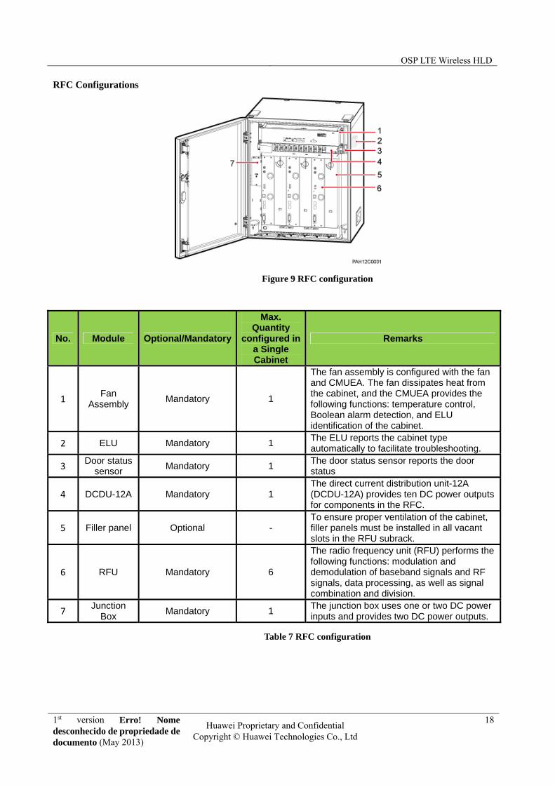
RFC Configurations
Figure 9 RFC configuration
No. Module Optional/Mandatory
Max. Quantity
configured in a Single Cabinet
Remarks
1 Fan
Assembly Mandatory 1
The fan assembly is configured with the fan and CMUEA. The fan dissipates heat from the cabinet, and the CMUEA provides the following functions: temperature control, Boolean alarm detection, and ELU identification of the cabinet.
2 ELU Mandatory 1 The ELU reports the cabinet type automatically to facilitate troubleshooting.
3 Door status
sensor Mandatory 1
The door status sensor reports the door status
4 DCDU-12A Mandatory 1 The direct current distribution unit-12A (DCDU-12A) provides ten DC power outputs for components in the RFC.
5 Filler panel Optional - To ensure proper ventilation of the cabinet, filler panels must be installed in all vacant slots in the RFU subrack.
6 RFU Mandatory 6
The radio frequency unit (RFU) performs the following functions: modulation and demodulation of baseband signals and RF signals, data processing, as well as signal combination and division.
7 Junction
Box Mandatory 1
The junction box uses one or two DC power inputs and provides two DC power outputs.
Table 7 RFC configuration
OSP LTE Wireless HLD
1st version Erro! Nome desconhecido de propriedade de documento (May 2013)
Huawei Proprietary and Confidential Copyright © Huawei Technologies Co., Ltd
19
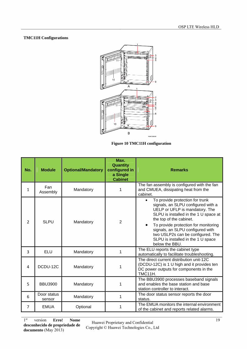
TMC11H Configurations
Figure 10 TMC11H configuration
No. Module Optional/Mandatory
Max. Quantity
configured in a Single Cabinet
Remarks
1 Fan
Assembly Mandatory 1
The fan assembly is configured with the fan and CMUEA, dissipating heat from the cabinet.
2 SLPU Mandatory 2
To provide protection for trunk signals, an SLPU configured with a UELP or UFLP is mandatory. The SLPU is installed in the 1 U space at the top of the cabinet.
To provide protection for monitoring signals, an SLPU configured with two USLP2s can be configured. The SLPU is installed in the 1 U space below the BBU.
3 ELU Mandatory 1 The ELU reports the cabinet type automatically to facilitate troubleshooting.
4 DCDU-12C Mandatory 1
The direct current distribution unit-12C (DCDU-12C) is 1 U high and it provides ten DC power outputs for components in the TMC11H.
5 BBU3900 Mandatory 1 The BBU3900 processes baseband signals and enables the base station and base station controller to interact.
6 Door status
sensor Mandatory 1
The door status sensor reports the door status.
7 EMUA Optional 1 The EMUA monitors the internal environment of the cabinet and reports related alarms.
OSP LTE Wireless HLD
1st version Erro! Nome desconhecido de propriedade de documento (May 2013)
Huawei Proprietary and Confidential Copyright © Huawei Technologies Co., Ltd
20
The EMUA must be configured when more than 16 Boolean alarm inputs are required and it is installed in the 1 U space below the BBU.
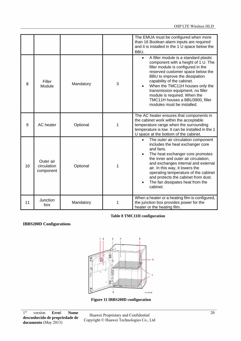
8 Filler
Module Mandatory 3
A filler module is a standard plastic component with a height of 1 U. The filler module is configured in the reserved customer space below the BBU to improve the dissipation capability of the cabinet.
When the TMC11H houses only the transmission equipment, no filler module is required. When the TMC11H houses a BBU3900, filler modules must be installed.
9 AC heater Optional 1
The AC heater ensures that components in the cabinet work within the acceptable temperature range when the surrounding temperature is low. It can be installed in the 1 U space at the bottom of the cabinet.
10 Outer air
circulation component
Optional 1
The outer air circulation component includes the heat exchanger core and fans.
The heat exchanger core promotes the inner and outer air circulation, and exchanges internal and external air. In this way, it lowers the operating temperature of the cabinet and protects the cabinet from dust.
The fan dissipates heat from the cabinet.
11 Junction
box Mandatory 1
When a heater or a heating film is configured, the junction box provides power for the heater or the heating film.
Table 8 TMC11H configuration
IBBS200D Configurations
Figure 11 IBBS200D configuration

OSP LTE Wireless HLD
1st version Erro! Nome desconhecido de propriedade de documento (May 2013)
Huawei Proprietary and Confidential Copyright © Huawei Technologies Co., Ltd
21
No. Module Optional/Mandatory
Max. Quantity
configured in a Single Cabinet
Remarks
1 Fan
mounting frame
Mandatory 1 The fan mounting frame is installed on the front door of the cabinet, and configured with a fan.
2
Central monitoring
unit type EA (CMUEA)
Mandatory 1
The CMUEA provides the following functions: temperature control, Boolean alarm detection, and ELU identification of the cabinet.
3 ELU Mandatory 1 The ELU reports the cabinet type automatically to facilitate troubleshooting.
4 Storage battery
Mandatory 8 The storage batteries provide long-duration backup power for a base station.
5 Power
distribution box
Mandatory 1
The power distribution box is installed on the inside of the upper right wall of the cabinet. It transfers and distributes power to the TEC or FAN unit and storage batteries.
6 Door status
sensor Mandatory 1
The door status sensor monitors whether the cabinet door is open.
7 Heating
Film Optional 2
The IBBS200D must be configured with a heating film in cold areas. The heating film is not required in general areas.
8
Junction terminal for
the input power cable
of the heating
Mandatory 1
The junction terminal provides the input power port for the heating film.
Table 9 IBBS200D configuration
3.2 Distributed Solution This section provides a full overview of the DBS3900 solution to be rolled-out. Note that all the information related to BBU design and board description applies to macro solution scenario.
3.2.1 BBU3900 slot design
The following figure shows the slots for the boards of BBU3900 that will be used and that can be configured by MML commands:

OSP LTE Wireless HLD
1st version Erro! Nome desconhecido de propriedade de documento (May 2013)
Huawei Proprietary and Confidential Copyright © Huawei Technologies Co., Ltd
22
3.2.2 Board introduction
UMPT
The universal main processing & transmission unit (UMPT) processes signals and manages resources on other boards in the BBU3900.The UMPT is classified into two types: UMPTa1 and UMPTa2. UMPTa2 board used for LTE mode and will be used during the deployment. The following table shows the specification of UMPTa2.
Board Applicable Mode Transmission Mode Port Port Capacity Full/Half-Duplex
UMPTa2 LTE IP over E1/T1 1 4 -
Transmission over FE/GE electrical ports
1 10 Mbit/s, 100 Mbit/s, and 1000 Mbit/s
Full-duplex
Transmission over FE/GE optical ports
1 100 Mbit/s and 1000 Mbit/s
Full- or half-duplex
UMPTa2 panel
Figure 12 UMPT board
The UMPT performs the following functions:
Performs configuration management, device management, performance monitoring, signaling message processing, and active/standby switchover
Controls all boards in the system
Provides a reference clock for the system
Board Type Slot: Board Type Slot: Board Type Slot: Board Type
16:FAN
0:LBBP / UCIU 4: LBBP /UTRP/ UCIU 18: UEIU
1: LBBP 5: LBBP /UTRP
2: LBBP 6:LMPT/ UMPT 19: UPEU
3: LBBP 7:LMPT /UMPT
OSP LTE Wireless HLD
1st version Erro! Nome desconhecido de propriedade de documento (May 2013)
Huawei Proprietary and Confidential Copyright © Huawei Technologies Co., Ltd
23
Implements transmission and provides absolute time and 1 pulse per second (PPS) clock source while being equipped with a satellite receiver
Provides four E1 ports and two FE/GE ports to implement basic transmission in compliance with Asynchronous Transfer Mode (ATM), Internet Protocol (IP), and Point-to-Point Protocol (PPP) during the initial configuration
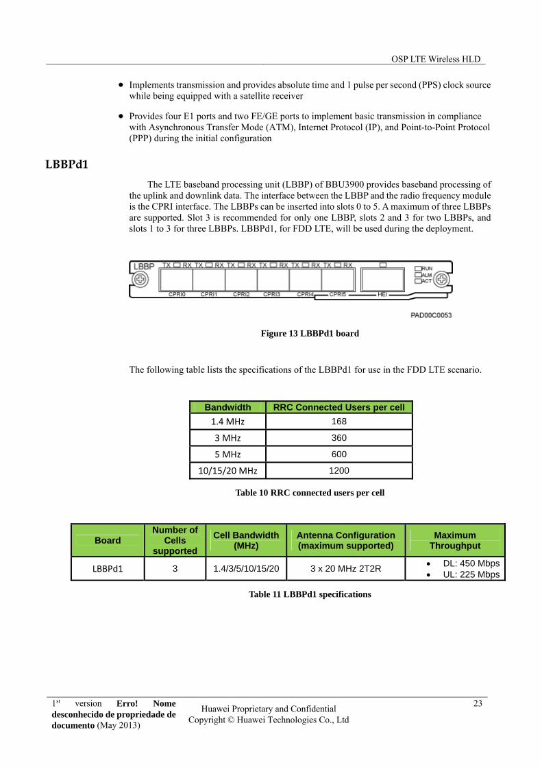
LBBPd1
The LTE baseband processing unit (LBBP) of BBU3900 provides baseband processing of the uplink and downlink data. The interface between the LBBP and the radio frequency module is the CPRI interface. The LBBPs can be inserted into slots 0 to 5. A maximum of three LBBPs are supported. Slot 3 is recommended for only one LBBP, slots 2 and 3 for two LBBPs, and slots 1 to 3 for three LBBPs. LBBPd1, for FDD LTE, will be used during the deployment.
Figure 13 LBBPd1 board
The following table lists the specifications of the LBBPd1 for use in the FDD LTE scenario.
Bandwidth RRC Connected Users per cell
1.4 MHz 168
3 MHz 360
5 MHz 600
10/15/20 MHz 1200
Table 10 RRC connected users per cell
Board Number of
Cells supported
Cell Bandwidth (MHz)
Antenna Configuration (maximum supported)
Maximum Throughput
LBBPd1 3 1.4/3/5/10/15/20 3 x 20 MHz 2T2R DL: 450 Mbps UL: 225 Mbps
Table 11 LBBPd1 specifications

OSP LTE Wireless HLD
1st version Erro! Nome desconhecido de propriedade de documento (May 2013)
Huawei Proprietary and Confidential Copyright © Huawei Technologies Co., Ltd
24
1. The LBBP can occupy slots 0 to 5. The order of preference is 3, 2, 1, 0, 5, and 4.
2. The LBBP should support radio interface bandwidth of 20 MHz. The rate of the optical module should be 2.5 Gbit/s or above. The optical module of the LMPT for S1/X2 transmission has no such restraint. Tests show that the rate of the optical module can be 1.25 Gbit/s.
UPEU
The universal power and environment interface unit (UPEU) for the BBU3900 converts -48 V DC or +24 V DC power into +12 V DC power.
Figure 14 UPEUc board. (1) BBU power switch; (2) 3V3 connector
The functions of the universal power and environment interface unit (UPEU) of BBU3900 are as follows:
Converts -48 VDC (UPEUa and UPEUc) or +24 VDC (UPEUb) into +12 V operating power.
UPEUc board has an output power of 360W.
Provides two RS485 signal interfaces and eight Boolean signal interfaces. Occupies slot 18 or 19. The UPEU in different slot provides different signal. For details, see the BBU3900 hardware description.
Provides anti inverse connection.
The UPEUc provides automatic current equalization and input power report. (Note: UPEUa and UPEUb do not have this function.)
The UPEU supports hot standby. If the active UPEU of the active/standby UPEUs is faulty or is plugged out, the services on the active UPEU are switched to the standby UPEU without affecting the eNodeB. (This function has been tested.)
UEIU
The universal environment interface unit (UEIU) of the BBU3900 transmits monitoring signals and alarm signals from external devices to the main control board.
Figure 15 UEIU board
OSP LTE Wireless HLD
1st version Erro! Nome desconhecido de propriedade de documento (May 2013)
Huawei Proprietary and Confidential Copyright © Huawei Technologies Co., Ltd
25
The UEIU performs the following functions:
Provides two ports with each receiving one path of RS485 signal.
Provides two ports with each receiving four paths of Boolean signals. These signals can only be dry contact or OC signals.
Transmits monitoring and alarms signals from external devices to the main control board.
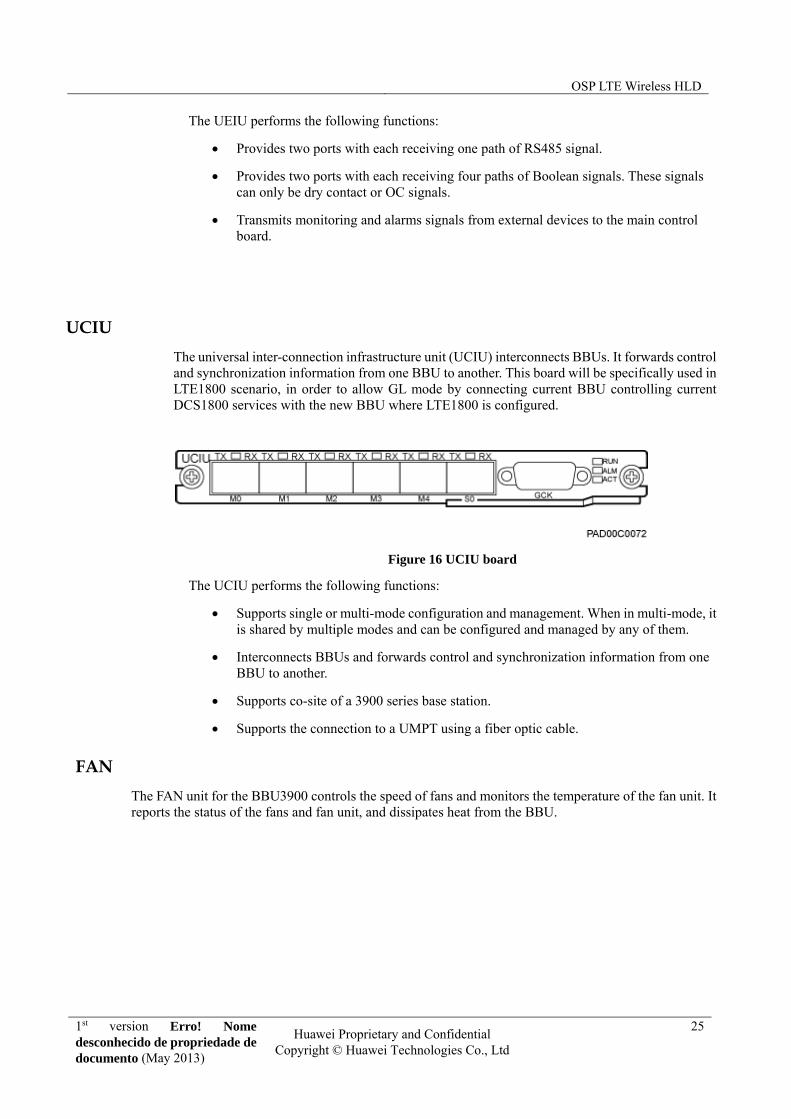
UCIU
The universal inter-connection infrastructure unit (UCIU) interconnects BBUs. It forwards control and synchronization information from one BBU to another. This board will be specifically used in LTE1800 scenario, in order to allow GL mode by connecting current BBU controlling current DCS1800 services with the new BBU where LTE1800 is configured.
Figure 16 UCIU board
The UCIU performs the following functions:
Supports single or multi-mode configuration and management. When in multi-mode, it is shared by multiple modes and can be configured and managed by any of them.
Interconnects BBUs and forwards control and synchronization information from one BBU to another.
Supports co-site of a 3900 series base station.
Supports the connection to a UMPT using a fiber optic cable.
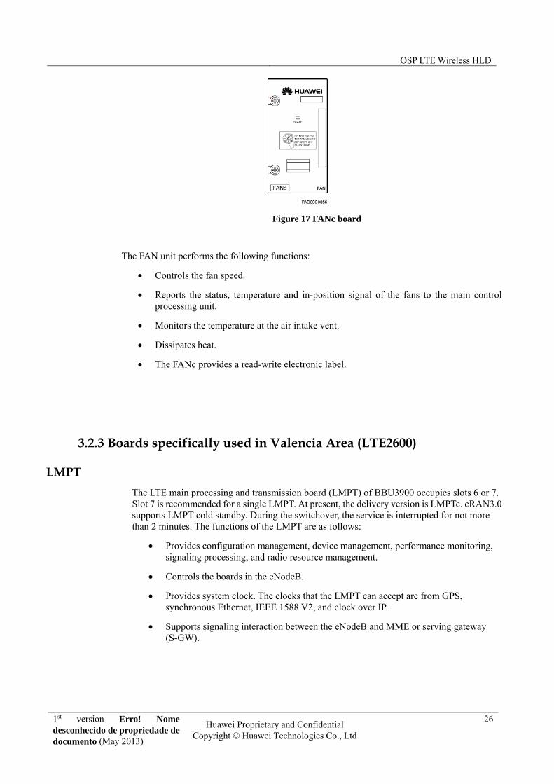
FAN
The FAN unit for the BBU3900 controls the speed of fans and monitors the temperature of the fan unit. It reports the status of the fans and fan unit, and dissipates heat from the BBU.
OSP LTE Wireless HLD
1st version Erro! Nome desconhecido de propriedade de documento (May 2013)
Huawei Proprietary and Confidential Copyright © Huawei Technologies Co., Ltd
26
Figure 17 FANc board
The FAN unit performs the following functions:
Controls the fan speed.
Reports the status, temperature and in-position signal of the fans to the main control processing unit.
Monitors the temperature at the air intake vent.
Dissipates heat.
The FANc provides a read-write electronic label.
3.2.3 Boards specifically used in Valencia Area (LTE2600)
LMPT
The LTE main processing and transmission board (LMPT) of BBU3900 occupies slots 6 or 7. Slot 7 is recommended for a single LMPT. At present, the delivery version is LMPTc. eRAN3.0 supports LMPT cold standby. During the switchover, the service is interrupted for not more than 2 minutes. The functions of the LMPT are as follows:
Provides configuration management, device management, performance monitoring, signaling processing, and radio resource management.
Controls the boards in the eNodeB.
Provides system clock. The clocks that the LMPT can accept are from GPS, synchronous Ethernet, IEEE 1588 V2, and clock over IP.
Supports signaling interaction between the eNodeB and MME or serving gateway (S-GW).

OSP LTE Wireless HLD
1st version Erro! Nome desconhecido de propriedade de documento (May 2013)
Huawei Proprietary and Confidential Copyright © Huawei Technologies Co., Ltd
27
Figure 18 LMPT board
1. The SFP0 and FE/GE0 interfaces of the LMPT are one GE transmission line. The two interfaces cannot be used simultaneously.
2. The SFP1 and FE/GE1 interfaces of the LMPT are one GE transmission line. The two interfaces cannot be used simultaneously.
LBBPc
Figure 19 LBBPc board
Board Number of
Cells supported
Cell Bandwidth (MHz)
Antenna Configuration (maximum supported)
Maximum Throughput
LBBPc 3 1.4/3/5/10/15/20 3 x 10 MHz 4T4R 3 x 20 MHz 2T2R 1 x 20 MHz 4T4R
DL: 300 Mbps UL: 300 Mbps
Table 12 LBBPc specifications
3.2.4 LTE 2600 MHz scenario
LTE 2600 MHz shall be supported with a new and separated BBU3900. To support the default configuration in the eNodeB (3 sectors with 20MHz and 2T2R antenna configuration), the BBU will be populated with one LTE Main Processing and Transmission Unit (UMPT), one LTE Base Band Processing board version C (LBBPc) and one Universal Power and Environment Interface Unit (UPEU).
Figure 20: BBU picture (left) and default LTE 2600 MHz configuration (right)
OSP LTE Wireless HLD
1st version Erro! Nome desconhecido de propriedade de documento (May 2013)
Huawei Proprietary and Confidential Copyright © Huawei Technologies Co., Ltd
28
NOTE: Sites already deployed in Orange City trial in Valencia will keep their current configuration, which is, using LTE Main Processing and Transmission Unit (LMPT).
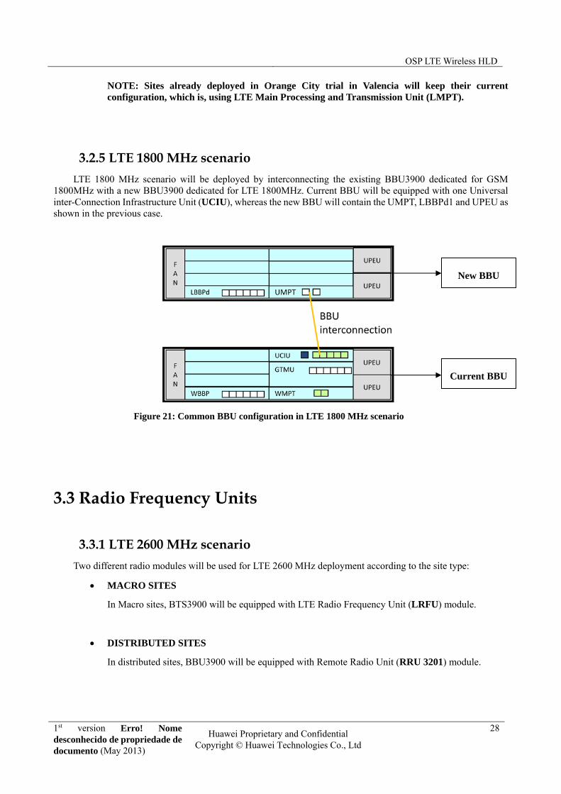
3.2.5 LTE 1800 MHz scenario
LTE 1800 MHz scenario will be deployed by interconnecting the existing BBU3900 dedicated for GSM 1800MHz with a new BBU3900 dedicated for LTE 1800MHz. Current BBU will be equipped with one Universal inter-Connection Infrastructure Unit (UCIU), whereas the new BBU will contain the UMPT, LBBPd1 and UPEU as shown in the previous case.
Figure 21: Common BBU configuration in LTE 1800 MHz scenario
3.3 Radio Frequency Units
3.3.1 LTE 2600 MHz scenario
Two different radio modules will be used for LTE 2600 MHz deployment according to the site type:
MACRO SITES
In Macro sites, BTS3900 will be equipped with LTE Radio Frequency Unit (LRFU) module.
DISTRIBUTED SITES
In distributed sites, BBU3900 will be equipped with Remote Radio Unit (RRU 3201) module.
Current BBU
New BBU

OSP LTE Wireless HLD
1st version Erro! Nome desconhecido de propriedade de documento (May 2013)
Huawei Proprietary and Confidential Copyright © Huawei Technologies Co., Ltd
29
3.3.2 LTE 1800 MHz scenario
Two different radio modules will be used for LTE 1800 MHz deployment according to the site type:
MACRO SITES
In Macro sites, BTS3900 will be equipped with Multi-mode Radio Frequency Unit (MRFU v2) module.
In order to achieve MIMO 2T2R configuration, these new modules will be cross-connected with the current DCS1800 MRFU v2 modules.
DISTRIBUTED SITES
In distributed sites, BBU3900 will be equipped with Remote Radio Unit (RRU 3929) module. In cases where there is an existing DCS1800 distributed solution, current RRU 3908v1 module should be swapped by the new one.
3.3.3 CPRI cabling design
There are multiple types of CPRI cabling, depending on the configuration of the sector and frequency band. The CPRI interfaces of the LBBP are connected in ascending order, beginning from CPRI 0.
1. The following figure shows the CPRI cabling of LBBP for the configuration of 3*20 MHz and 2T2R in DBS3900 scenario. RRUs are connected to ports [0-2].
Figure 22: CPRI cabling design in DBS3900 scenario
OSP LTE Wireless HLD
1st version Erro! Nome desconhecido de propriedade de documento (May 2013)
Huawei Proprietary and Confidential Copyright © Huawei Technologies Co., Ltd
30
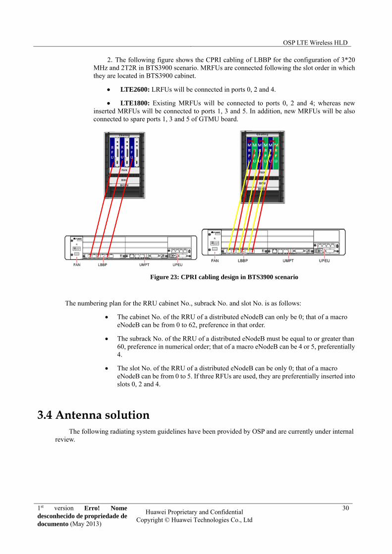
2. The following figure shows the CPRI cabling of LBBP for the configuration of 3*20 MHz and 2T2R in BTS3900 scenario. MRFUs are connected following the slot order in which they are located in BTS3900 cabinet.
LTE2600: LRFUs will be connected in ports 0, 2 and 4.
LTE1800: Existing MRFUs will be connected to ports 0, 2 and 4; whereas new inserted MRFUs will be connected to ports 1, 3 and 5. In addition, new MRFUs will be also connected to spare ports 1, 3 and 5 of GTMU board.
Figure 23: CPRI cabling design in BTS3900 scenario
The numbering plan for the RRU cabinet No., subrack No. and slot No. is as follows:
The cabinet No. of the RRU of a distributed eNodeB can only be 0; that of a macro eNodeB can be from 0 to 62, preference in that order.
The subrack No. of the RRU of a distributed eNodeB must be equal to or greater than 60, preference in numerical order; that of a macro eNodeB can be 4 or 5, preferentially 4.
The slot No. of the RRU of a distributed eNodeB can be only 0; that of a macro eNodeB can be from 0 to 5. If three RFUs are used, they are preferentially inserted into slots 0, 2 and 4.
3.4 Antenna solution The following radiating system guidelines have been provided by OSP and are currently under internal
review.
OSP LTE Wireless HLD
1st version Erro! Nome desconhecido de propriedade de documento (May 2013)
Huawei Proprietary and Confidential Copyright © Huawei Technologies Co., Ltd
31
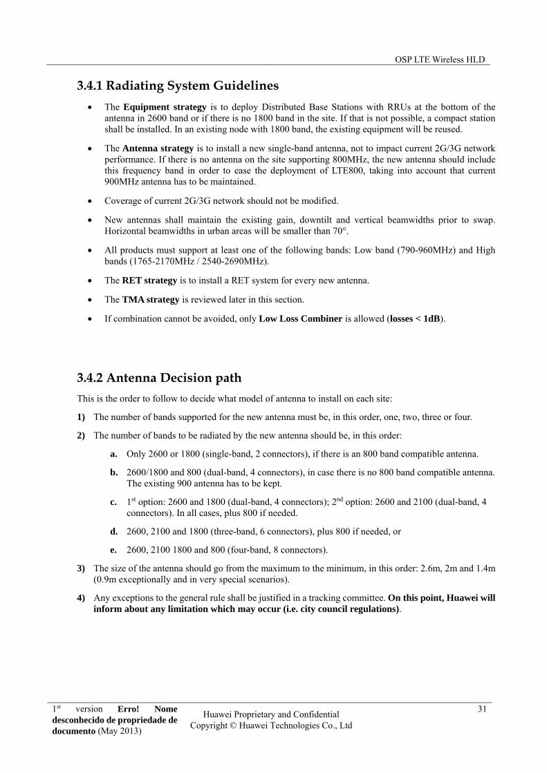
3.4.1 Radiating System Guidelines
The Equipment strategy is to deploy Distributed Base Stations with RRUs at the bottom of the antenna in 2600 band or if there is no 1800 band in the site. If that is not possible, a compact station shall be installed. In an existing node with 1800 band, the existing equipment will be reused.
The Antenna strategy is to install a new single-band antenna, not to impact current 2G/3G network performance. If there is no antenna on the site supporting 800MHz, the new antenna should include this frequency band in order to ease the deployment of LTE800, taking into account that current 900MHz antenna has to be maintained.
Coverage of current 2G/3G network should not be modified.
New antennas shall maintain the existing gain, downtilt and vertical beamwidths prior to swap. Horizontal beamwidths in urban areas will be smaller than 70°.
All products must support at least one of the following bands: Low band (790-960MHz) and High bands (1765-2170MHz / 2540-2690MHz).
The RET strategy is to install a RET system for every new antenna.
The TMA strategy is reviewed later in this section.
If combination cannot be avoided, only Low Loss Combiner is allowed (losses < 1dB).
3.4.2 Antenna Decision path
This is the order to follow to decide what model of antenna to install on each site:
1) The number of bands supported for the new antenna must be, in this order, one, two, three or four.
2) The number of bands to be radiated by the new antenna should be, in this order:
a. Only 2600 or 1800 (single-band, 2 connectors), if there is an 800 band compatible antenna.
b. 2600/1800 and 800 (dual-band, 4 connectors), in case there is no 800 band compatible antenna. The existing 900 antenna has to be kept.
c. 1st option: 2600 and 1800 (dual-band, 4 connectors); 2nd option: 2600 and 2100 (dual-band, 4 connectors). In all cases, plus 800 if needed.
d. 2600, 2100 and 1800 (three-band, 6 connectors), plus 800 if needed, or
e. 2600, 2100 1800 and 800 (four-band, 8 connectors).
3) The size of the antenna should go from the maximum to the minimum, in this order: 2.6m, 2m and 1.4m (0.9m exceptionally and in very special scenarios).
4) Any exceptions to the general rule shall be justified in a tracking committee. On this point, Huawei will inform about any limitation which may occur (i.e. city council regulations).
OSP LTE Wireless HLD
1st version Erro! Nome desconhecido de propriedade de documento (May 2013)
Huawei Proprietary and Confidential Copyright © Huawei Technologies Co., Ltd
32
3.4.3 Antenna model selection
Find attached the proposed antenna models by OSP. Target antenna installation will follow the recommendations provided by site survey. This section should be updated with the final antenna models selected.
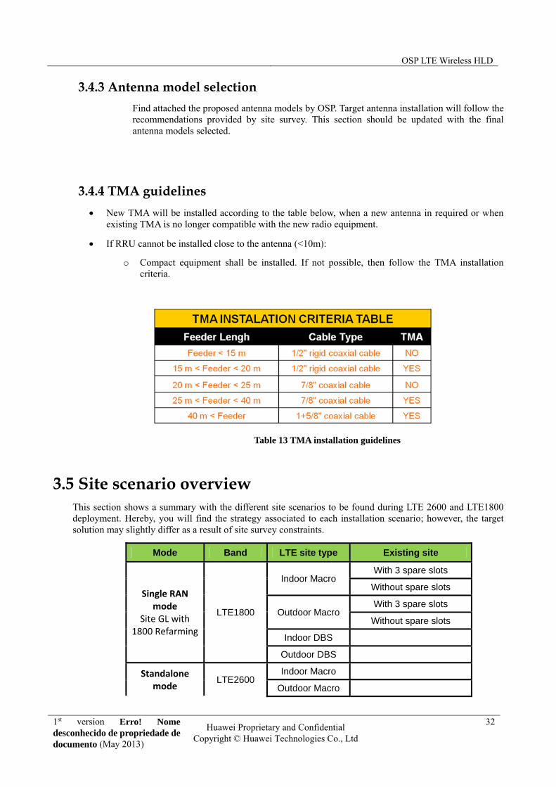
3.4.4 TMA guidelines
New TMA will be installed according to the table below, when a new antenna in required or when existing TMA is no longer compatible with the new radio equipment.
If RRU cannot be installed close to the antenna (<10m):
o Compact equipment shall be installed. If not possible, then follow the TMA installation criteria.
Table 13 TMA installation guidelines
3.5 Site scenario overview This section shows a summary with the different site scenarios to be found during LTE 2600 and LTE1800 deployment. Hereby, you will find the strategy associated to each installation scenario; however, the target solution may slightly differ as a result of site survey constraints.
Mode Band LTE site type Existing site
Single RAN mode
Site GL with 1800 Refarming
LTE1800
Indoor Macro With 3 spare slots
Without spare slots
Outdoor Macro With 3 spare slots
Without spare slots
Indoor DBS
Outdoor DBS
Standalone mode
LTE2600 Indoor Macro
Outdoor Macro

OSP LTE Wireless HLD
1st version Erro! Nome desconhecido de propriedade de documento (May 2013)
Huawei Proprietary and Confidential Copyright © Huawei Technologies Co., Ltd
33
Indoor DBS
Outdoor DBS
Table 14 Site scenario summary
3.5.1 Indoor DBS single band LTE2600
Key points:
New IMB is needed for accommodating BBU and provide DC power to LTE RRU3221. This new IMB will be installed on the wall inside the shelter.
The power cable of RRU3221 can be 4mm if the length is less than 70m.
If there is no space for IMB, the new BBU will be installed in existing 19” rack and DCDU into the existing IMB
Figure 24: Indoor DBS single band LTE2600 scenario
3.5.2 Indoor macro single band LTE2600
Key points:
New BTS3900 will be installed and site power assessment needs to be considered.
New LRFUs shall be installed.

OSP LTE Wireless HLD
1st version Erro! Nome desconhecido de propriedade de documento (May 2013)
Huawei Proprietary and Confidential Copyright © Huawei Technologies Co., Ltd
34
Figure 25: Indoor macro single band LTE2600 scenario
3.5.3 Outdoor DBS single band LTE2600
Key points:
New BTS3900A (APM30H + IBBS200D) will be installed and site power assessment needs to be considered.
RRU3221 shall be installed.
Figure 26: Outdoor DBS single band LTE2600 scenario
3.5.4 Outdoor macro single band LTE2600
Key points:

OSP LTE Wireless HLD
1st version Erro! Nome desconhecido de propriedade de documento (May 2013)
Huawei Proprietary and Confidential Copyright © Huawei Technologies Co., Ltd
35
New BTS3900A (APM30H + RFC + IBBS200D) will be installed and site power assessment needs to be considered.
LRFU shall be installed.
Figure 27: Outdoor macro single band LTE2600 scenario
3.5.5 Indoor macro single band LTE1800 with 3 spare slots
Key points:
New MRFUs will be installed in the spare slots of existing BTS3900 and cross-connected with the ones used for G1800 in order to configure 2T2R MIMO.
If the existing site is GSM only, then UMPT and LBBPd boards can be inserted into the existing BBU, no need to add the 2nd BBU with UCIU board.
If the existing site is GU, a second BBU must be added which can be installed into existing IMB or cabinet. UCIU is added into the existing BBU to interconnect both BBUs, so GL1800 can work in single RAN mode.
If total number of RF Unit with GSM is more than 6, an UBRI board should be added into the existing BBU.
Current pair of feeders per sector will be reused, connecting the first one to current MRFU and the second one to the new installed MRFU.

OSP LTE Wireless HLD
1st version Erro! Nome desconhecido de propriedade de documento (May 2013)
Huawei Proprietary and Confidential Copyright © Huawei Technologies Co., Ltd
36
Figure 28: Indoor macro single band LTE1800 scenario with 3 spare slots
3.5.6 Indoor macro single band LTE1800 without spare slots
Key points:
New BTS3900 is required. The installation strategy is to move the current WRFU controlling U2100 into the new BTS3900 cabinet and to insert new MRFUs into the released slots, to allow combination with current G18000 MRFUs.
A second BBU must be added which can be installed into the new cabinet. UCIU is added into the existing BBU to interconnect both BBUs, so GL1800 can work in single RAN mode.
Current pair of feeders per sector will be reused, connecting the first one to current MRFU and the second one to the new installed MRFU.

OSP LTE Wireless HLD
1st version Erro! Nome desconhecido de propriedade de documento (May 2013)
Huawei Proprietary and Confidential Copyright © Huawei Technologies Co., Ltd
37
Figure 29: Indoor macro single band LTE1800 scenario without spare slots
3.5.7 Outdoor macro single band LTE1800 with 3 spare slots
Key points:
New MRFUs will be installed in the spare slots of existing BTS3900A and cross-connected with the ones used for G1800 in order to configure 2T2R MIMO.
If the existing site is GSM only, then UMPT and LBBPd boards can be inserted into the existing BBU, no need to add the 2nd BBU with UCIU board.
If the existing site is GU, a second BBU must be added which can be installed into existing APM30H or cabinet. UCIU is added into the existing BBU to interconnect both BBUs, so GL1800 can work in single RAN mode.
If total number of RF Unit with GSM is more than 6, an UBRI board should be added into the existing BBU.
Current pair of feeders per sector will be reused, connecting the first one to current MRFU and the second one to the new installed MRFU.
OSP LTE Wireless HLD
1st version Erro! Nome desconhecido de propriedade de documento (May 2013)
Huawei Proprietary and Confidential Copyright © Huawei Technologies Co., Ltd
38
Figure 30: Outdoor macro single band LTE1800 with 3 spare slots
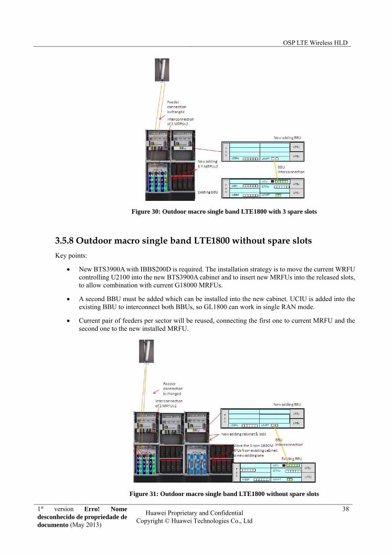
3.5.8 Outdoor macro single band LTE1800 without spare slots
Key points:
New BTS3900A with IBBS200D is required. The installation strategy is to move the current WRFU controlling U2100 into the new BTS3900A cabinet and to insert new MRFUs into the released slots, to allow combination with current G18000 MRFUs.
A second BBU must be added which can be installed into the new cabinet. UCIU is added into the existing BBU to interconnect both BBUs, so GL1800 can work in single RAN mode.
Current pair of feeders per sector will be reused, connecting the first one to current MRFU and the second one to the new installed MRFU.
Figure 31: Outdoor macro single band LTE1800 without spare slots

OSP LTE Wireless HLD
1st version Erro! Nome desconhecido de propriedade de documento (May 2013)
Huawei Proprietary and Confidential Copyright © Huawei Technologies Co., Ltd
39
3.5.9 Indoor DBS single band LTE1800
Key points:
If the existing site is GU, a second BBU is required. This new BBU can be installed into the existing IMB (or in a new IMB where required). UCIU board will be added into the existing BBU in order to interconnect both BBUs, as explained in previous scenarios.
The section of power cable of RRU3929 can be 6mm if the length is less than 70m and 8mm for extended lengths.
RRU3929 will replace current RRU3908 version. Each RRU will be connected to both BBUs with individual CPRI cables.
Figure 32: Indoor DBS single band LTE1800
3.5.10 Outdoor DBS single band LTE1800
Key points:
New BTS3900A (APM30H + IBBS200D) will be installed and site power assessment needs to be considered.
If the existing site is GU, a new BBU is required and can be installed into the new additional TMC (whenever current site has only 1xAPM30H) or into the existing AMP30H (whenever the site has already 2x APM30H). UCIU is added into the existing BBU to interconnect the 2 BBUs
RRU3929 will replace current RRU3908 version. Each RRU will be connected to both BBUs with individual CPRI cables.

OSP LTE Wireless HLD
1st version Erro! Nome desconhecido de propriedade de documento (May 2013)
Huawei Proprietary and Confidential Copyright © Huawei Technologies Co., Ltd
40
Figure 33: Outdoor DBS single band LTE1800
OSP LTE Wireless HLD
1st version Erro! Nome desconhecido de propriedade de documento (May 2013)
Huawei Proprietary and Confidential Copyright © Huawei Technologies Co., Ltd
41
4 Software
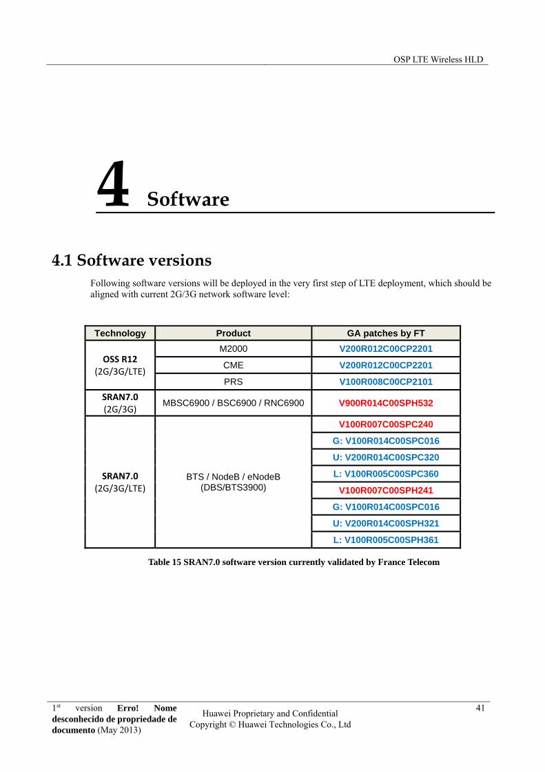
4.1 Software versions Following software versions will be deployed in the very first step of LTE deployment, which should be aligned with current 2G/3G network software level:
Technology Product GA patches by FT
OSS R12 (2G/3G/LTE)
M2000 V200R012C00CP2201
CME V200R012C00CP2201
PRS V100R008C00CP2101
SRAN7.0 (2G/3G)
MBSC6900 / BSC6900 / RNC6900 V900R014C00SPH532
SRAN7.0 (2G/3G/LTE)
BTS / NodeB / eNodeB (DBS/BTS3900)
V100R007C00SPC240
G: V100R014C00SPC016
U: V200R014C00SPC320
L: V100R005C00SPC360
V100R007C00SPH241
G: V100R014C00SPC016
U: V200R014C00SPH321
L: V100R005C00SPH361
Table 15 SRAN7.0 software version currently validated by France Telecom

OSP LTE Wireless HLD
1st version Erro! Nome desconhecido de propriedade de documento (May 2013)
Huawei Proprietary and Confidential Copyright © Huawei Technologies Co., Ltd
42
4.2 Feature List
4.2.1 LTE FDD eRAN3.0 feature list
In the following excel file, there is a list of features, basic and optional. In addition, it can be checked the customized feature selection for current network deployment and strategy and highlighting which ones will be tested during FOA.
Further information about each one of these features can be found in eRAN3.0 LTE FDD Feature Description documentation.
4.2.2 CS fallback strategy
CS fallback (CSFB) is migration solution for voice call setup before VoIP over LTE is available.
When voice service is originated or terminated in LTE, LTE/EPC would do CSFB to UMTS. Based on OSP network background, LTE CS service is preferentially to UMTS F1 frequency.
When UE completes voice service in UMTS, then
- If concurrent PS service exists, UE would do redirection with measurement to LTE to get higher throughput in case UE supports redirection to LTE, otherwise, UE would transit to Idle/Cell PCH state, then return back to LTE by cell reselection strategy when PS service completes in UMTS.
- If no concurrent PS service exists , UE would transit to Idle/Cell PCH state, then return back to LTE by cell reselection strategy
Find attached Huawei’s proposal for CSFB strategy.
4.2.3 eNodeB in pool strategy
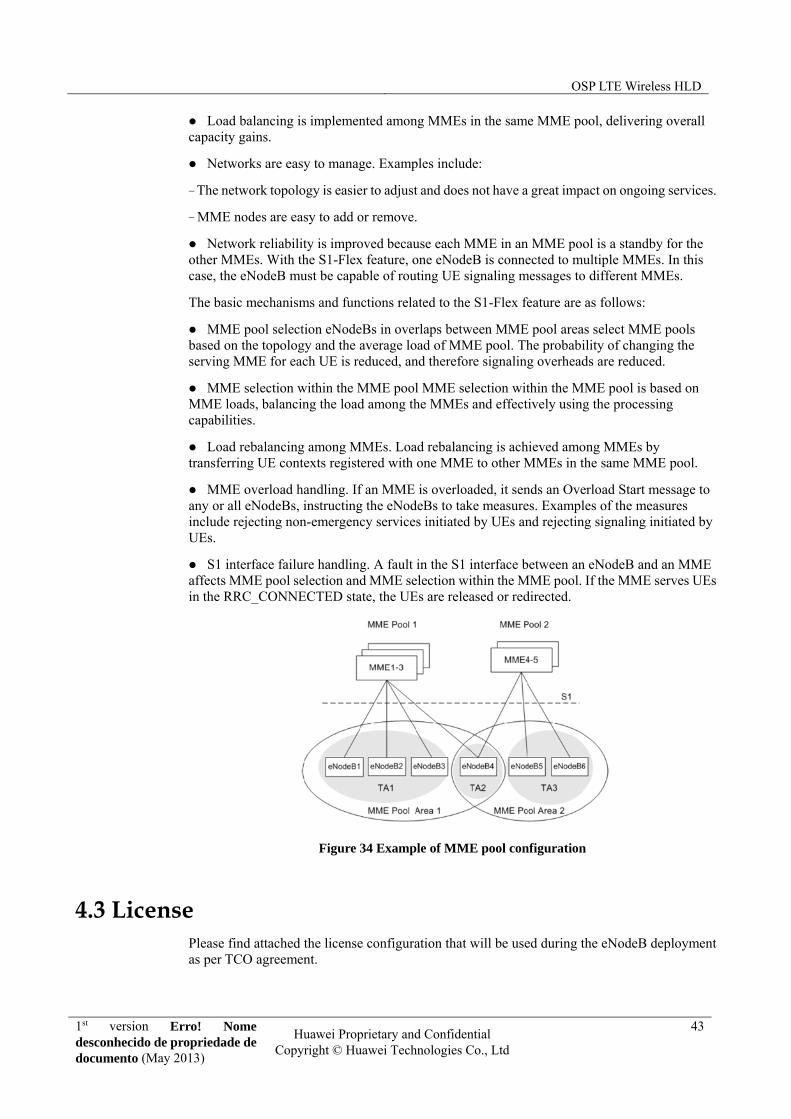
OSP EPC network will follow a MME pool strategy. That will allow the eNodeB to set up multiple S1 interfaces with different MMEs to ensure robustness and redundancy. In order to allow this architecture, S1-flex feature will be deployed in eNodeB.
S1-flex on an LTE network is a feature that enables one eNodeB to set up S1-MME connections to multiple MMEs, which form a resource pool, know as an MME pool. When a UE accesses the network through an eNodeB, the eNodeB selects a serving MME for the UE and sets up a dedicated S1-MME connection.
The S1-Flex feature provides the following benefits:
Signaling overheads in transmission and processing are reduced because the serving MME for a UE does not need to be changed when the UE moves within an MME pool area (the area covered by an MME pool).
OSP LTE Wireless HLD
1st version Erro! Nome desconhecido de propriedade de documento (May 2013)
Huawei Proprietary and Confidential Copyright © Huawei Technologies Co., Ltd
43
Load balancing is implemented among MMEs in the same MME pool, delivering overall capacity gains.
Networks are easy to manage. Examples include:
− The network topology is easier to adjust and does not have a great impact on ongoing services.
− MME nodes are easy to add or remove.
Network reliability is improved because each MME in an MME pool is a standby for the other MMEs. With the S1-Flex feature, one eNodeB is connected to multiple MMEs. In this case, the eNodeB must be capable of routing UE signaling messages to different MMEs.
The basic mechanisms and functions related to the S1-Flex feature are as follows:
MME pool selection eNodeBs in overlaps between MME pool areas select MME pools based on the topology and the average load of MME pool. The probability of changing the serving MME for each UE is reduced, and therefore signaling overheads are reduced.
MME selection within the MME pool MME selection within the MME pool is based on MME loads, balancing the load among the MMEs and effectively using the processing capabilities.
Load rebalancing among MMEs. Load rebalancing is achieved among MMEs by transferring UE contexts registered with one MME to other MMEs in the same MME pool.
MME overload handling. If an MME is overloaded, it sends an Overload Start message to any or all eNodeBs, instructing the eNodeBs to take measures. Examples of the measures include rejecting non-emergency services initiated by UEs and rejecting signaling initiated by UEs.
S1 interface failure handling. A fault in the S1 interface between an eNodeB and an MME affects MME pool selection and MME selection within the MME pool. If the MME serves UEs in the RRC_CONNECTED state, the UEs are released or redirected.
Figure 34 Example of MME pool configuration
4.3 License Please find attached the license configuration that will be used during the eNodeB deployment as per TCO agreement.

OSP LTE Wireless HLD
1st version Erro! Nome desconhecido de propriedade de documento (May 2013)
Huawei Proprietary and Confidential Copyright © Huawei Technologies Co., Ltd
44
5 Radio network planning and optimization
This section details RNO/RNP strategy to be followed during OSP LTE project. In the attached documentation you can find the information associated to: refarming, cell planning, mobility management planning, network parameterization and KPI and counters.
Information related to eNodeB ID/cell ID and naming criteria are described within this chapter. These guidelines are aligned with the following documentation provided by OSP:
5.1 eNodeB Naming and Numbering rule design
5.1.1 eUTRAN Cell ID and eNodeB ID
The Cell Global Identity (CGI) is a specific ID which can uniquely identify a cell in the whole world. As Figure 7 states, CGI is composed of PLMN ID + Cell identifier, where PLMN = MCC + MNC and Cell Identifier contains the eNodeB ID.
Figure 35: Cell Identifier coding
The rule for calculating the eUTRAN cell ID is given by the formula:
OSP LTE Wireless HLD
1st version Erro! Nome desconhecido de propriedade de documento (May 2013)
Huawei Proprietary and Confidential Copyright © Huawei Technologies Co., Ltd
45
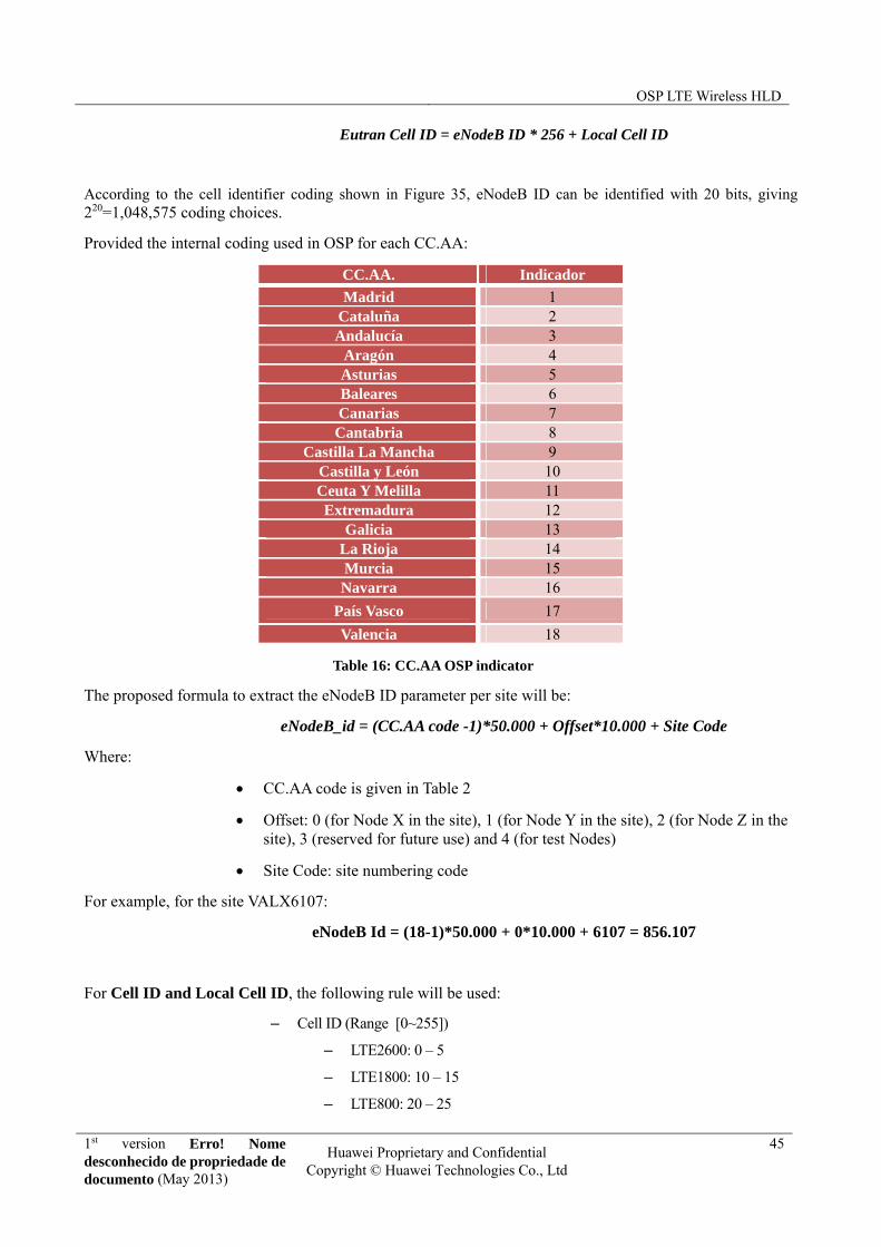
Eutran Cell ID = eNodeB ID * 256 + Local Cell ID
According to the cell identifier coding shown in Figure 35, eNodeB ID can be identified with 20 bits, giving 220=1,048,575 coding choices.
Provided the internal coding used in OSP for each CC.AA:
CC.AA. Indicador
Madrid 1 Cataluña 2 Andalucía 3
Aragón 4 Asturias 5 Baleares 6 Canarias 7 Cantabria 8
Castilla La Mancha 9 Castilla y León 10 Ceuta Y Melilla 11 Extremadura 12
Galicia 13 La Rioja 14 Murcia 15 Navarra 16
País Vasco 17
Valencia 18
Table 16: CC.AA OSP indicator
The proposed formula to extract the eNodeB ID parameter per site will be:
eNodeB_id = (CC.AA code -1)*50.000 + Offset*10.000 + Site Code
Where:
CC.AA code is given in Table 2
Offset: 0 (for Node X in the site), 1 (for Node Y in the site), 2 (for Node Z in the site), 3 (reserved for future use) and 4 (for test Nodes)
Site Code: site numbering code
For example, for the site VALX6107:
eNodeB Id = (18-1)*50.000 + 0*10.000 + 6107 = 856.107
For Cell ID and Local Cell ID, the following rule will be used:
– Cell ID (Range [0~255])
– LTE2600: 0 – 5
– LTE1800: 10 – 15
– LTE800: 20 – 25

OSP LTE Wireless HLD
1st version Erro! Nome desconhecido de propriedade de documento (May 2013)
Huawei Proprietary and Confidential Copyright © Huawei Technologies Co., Ltd
46
– Local Cell ID (Range [0~11])
– LTE2600: LCI: 0 – 5 for CI: 0 – 5
– LTE1800: LCI: 6 – 11 for CI: 10 – 15
– LTE800: LCI: 12 – 17 for CI: 20 – 25
And for Cell Name:
- Cell name (length [1~99])
- Format: Same format than UMTS and GSM cells changing technology code:
o LTE 2600 L
o LTE 800 M
o LTE 1800 N
- Example: V0001L1
The following table shows an example for Site ID and eNodeB ID:
eNodeB Name eNodeB ID Cell ID Cell Name Band
VALX0001 800001 0 V0001L1 2600MHz
VALX0001 800001 10 V0001N1 1800MHz
VALX0001 800001 20 V0001M1 800MHz
Table 17 Site ID & eNodeB ID example
5.2 eNodeB naming criteria A maximum of 64 characters uniquely identify an eNodeB within a PLMN, which will be displayed in M2000
system. The proposed naming criteria should be ZZZHABCD, where:
ZZZ: prefix for CC.AA. (AND Andalucía, MAD Madrid and so on)
H: indicates de independent node of the site. It should be X, Y or Z, depending on the criteria that introducing a new BBU would create a new logical entity in the OSS, in this case Y or Z (if Y exists) should be used.
Depending on the SW version the maximum number of BBUs should be grouped.
ABCD: code in each CC.AA. Each province has a range of CC.AA defined by OSP.
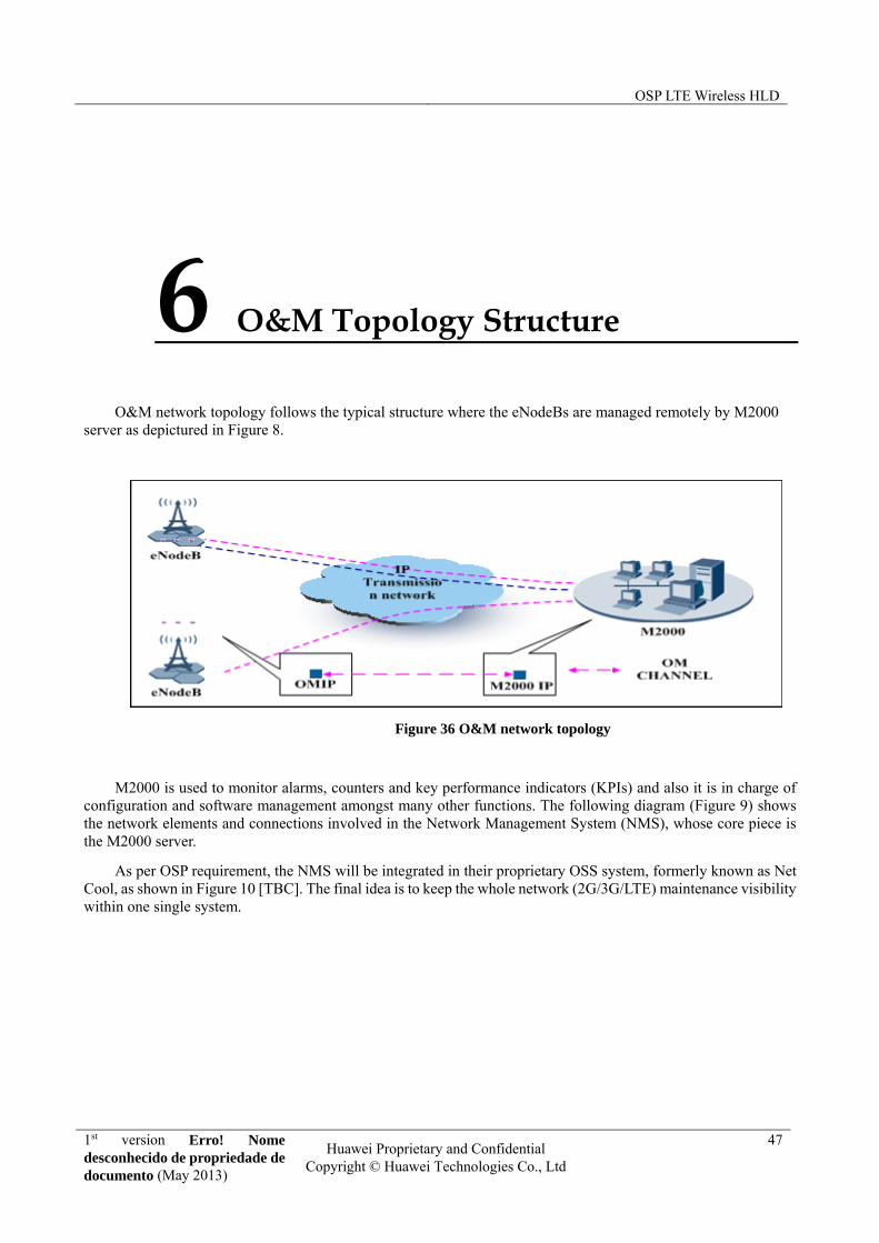
OSP LTE Wireless HLD
1st version Erro! Nome desconhecido de propriedade de documento (May 2013)
Huawei Proprietary and Confidential Copyright © Huawei Technologies Co., Ltd
47
6 O&M Topology Structure
O&M network topology follows the typical structure where the eNodeBs are managed remotely by M2000 server as depictured in Figure 8.
Figure 36 O&M network topology
M2000 is used to monitor alarms, counters and key performance indicators (KPIs) and also it is in charge of configuration and software management amongst many other functions. The following diagram (Figure 9) shows the network elements and connections involved in the Network Management System (NMS), whose core piece is the M2000 server.
As per OSP requirement, the NMS will be integrated in their proprietary OSS system, formerly known as Net Cool, as shown in Figure 10 [TBC]. The final idea is to keep the whole network (2G/3G/LTE) maintenance visibility within one single system.
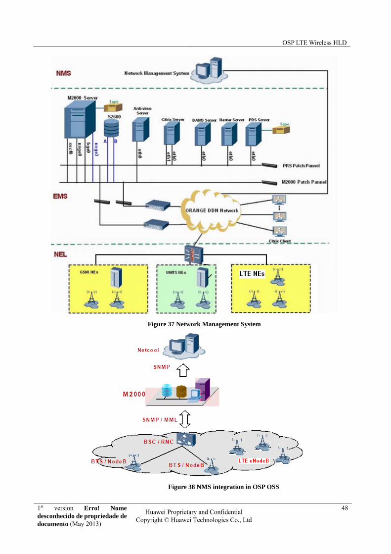
OSP LTE Wireless HLD
1st version Erro! Nome desconhecido de propriedade de documento (May 2013)
Huawei Proprietary and Confidential Copyright © Huawei Technologies Co., Ltd
48
Figure 37 Network Management System
Figure 38 NMS integration in OSP OSS
OSP LTE Wireless HLD
1st version Erro! Nome desconhecido de propriedade de documento (May 2013)
Huawei Proprietary and Confidential Copyright © Huawei Technologies Co., Ltd
49
7 Interface IP design and traffic flows
7.1 IP addressing scheme and VLAN proposal
7.1.1 Gerneral IP addressing scheme
The proposed eNodeB IP configuration proposed by Huawei considers two different TX network scenarios: Packet Microwave (PMW) and Fiber to the Node (FTTN).
Two IP addresses will differentiate the two kind of services associated to the eNodeB:
IP@1-LTE Traffic (S1/X2 interfaces): 10.38.0.0/16 subnet will be used in this case. Depending on the scenario, a different subnet mask will be assigned:
o /29 subnet for FTTN scenarios, where exists a direct connection between the eNodeB and the TX NE (i.e. PTNxxx).
o /27 subnet for PMW scenarios, where many eNodeBs (up to 3) are connected to a single PTN with PMW connections
IP@2-LTE O&M:10.24.128.0/17 subnet will be assigned for OMCH IP addressing scheme.
7.1.2 FTTN scenario
With a /29 subnet available, the following IP address distribution will be used: 5 IPs per LTE site, where 1 of them is used for S1/X2 interface traffic and the remaining 4 will be reserved for future use (see Table 9). In addition, the eNodeB will have the extra OMCH IP address.
In these cases, 2 VLAN per eNodeB will be used, one for data traffic and another for management.

OSP LTE Wireless HLD
1st version Erro! Nome desconhecido de propriedade de documento (May 2013)
Huawei Proprietary and Confidential Copyright © Huawei Technologies Co., Ltd
50
IP address
Description
IP@1 Subnet IP@
IP@2 PTN interface IP@
IP@3 eNodeB S1/X2 IP@
IP@4 Reserved
IP@5 Reserved
IP@6 Reserved
IP@7 Reserved
IP@8 Broadcast IP@
Table 18 IP addressing strategy for FTTN sites
Figure 39 Transmission network topology in FTTN scenarios. Note that VLAN A will be used for S1/X2 traffic data, whereas VLAN B will be applied to OMCH scenario. A unique VLAN A and VLAN B will be used per each eNodeB
7.1.3 PMW scenario
With a /27 subnet available, the following IP address distribution will be used (3 eNodeBs will be covered per subnet): 5 IPs per LTE site, where 1 of them is used for S1/X2 interface traffic and the remaining 4 will be reserved for future use. In addition, the eNodeB will have the extra OMCH IP address.
In these cases, 2 VLAN will be used as well; however, the same VLAN ID will be shared by up to 3 eNodeBs.

OSP LTE Wireless HLD
1st version Erro! Nome desconhecido de propriedade de documento (May 2013)
Huawei Proprietary and Confidential Copyright © Huawei Technologies Co., Ltd
51
Figure 40 Transmission network topology in PMW scenarios. Note that VLAN A will be used for S1/X2 traffic data, whereas VLAN B will be applied to OMCH scenario. Both VLAN A and VLAN B will be shared between all the eNodeBs under the same POC.
7.2 Traffic flows
7.2.1 S1 interface traffic flow
As stated in section 2, as far as eNodeB is concerned S1 interface is divided in two different logical entities, S1-C for control plane traffic and S1-U for user data traffic.
However, in the Evolved Packet Core (EPC) side, the S1 interface is physically divided into two different interfaces, connecting the eNodeB to both Mobility Management Entity (MME) and Serving Gateway (SGW).
The relevant IP connectivity data for S1 interface is defined in the following tables and excel file:
IP Addressing - EPC_nodes_PA11.xls
S1-MME physical IP interface
Service Name Network Subnet
S1‐MME‐1 S1-Range 10.31.1.16/29
Table 19 MME service IP addressing scheme.
S1-MME SCTP Profile
Service Name bunt assrtx pathtrx irto minrto maxrto Portno
S1‐MME 0 20 10 200 100 400 36412
Table 20 MME SCTP parameters
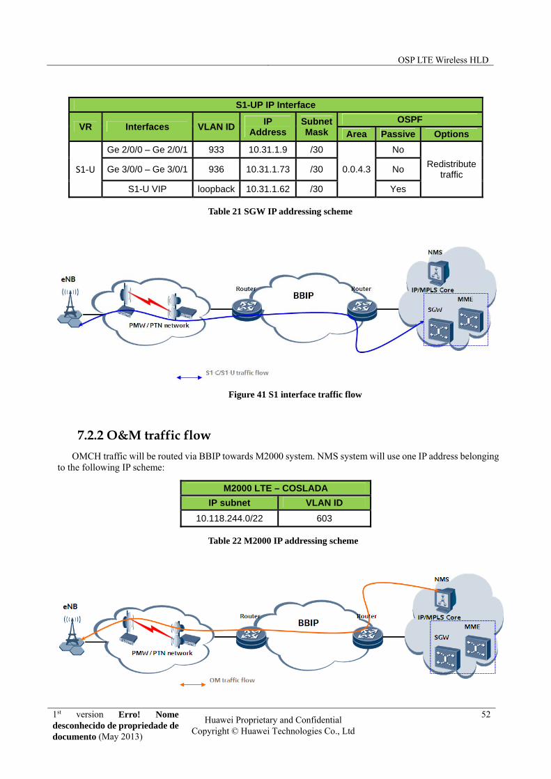
OSP LTE Wireless HLD
1st version Erro! Nome desconhecido de propriedade de documento (May 2013)
Huawei Proprietary and Confidential Copyright © Huawei Technologies Co., Ltd
52
S1-UP IP Interface
VR Interfaces VLAN IDIP
Address Subnet Mask
OSPF
Area Passive Options
Ge 2/0/0 – Ge 2/0/1 933 10.31.1.9 /30 No
S1‐U Ge 3/0/0 – Ge 3/0/1 936 10.31.1.73 /30 0.0.4.3 No Redistribute
traffic
S1-U VIP loopback 10.31.1.62 /30 Yes
Table 21 SGW IP addressing scheme
Figure 41 S1 interface traffic flow
7.2.2 O&M traffic flow
OMCH traffic will be routed via BBIP towards M2000 system. NMS system will use one IP address belonging to the following IP scheme:
M2000 LTE – COSLADA
IP subnet VLAN ID
10.118.244.0/22 603
Table 22 M2000 IP addressing scheme

OSP LTE Wireless HLD
1st version Erro! Nome desconhecido de propriedade de documento (May 2013)
Huawei Proprietary and Confidential Copyright © Huawei Technologies Co., Ltd
53
Figure 42 O&M traffic flow
7.2.3 X2 interface traffic flow
Two different types of X2 interface traffic can be differentiated:
Intra-POP X2 traffic: X2 traffic between 2 eNodeBs belonging to the same POP will be routed at POP level.
Inter-POP X2 traffic: X2 traffic between 2 eNodeBs belonging to different POP will be routed at BBIP level.
Figure 43 X2 interface traffic flow

OSP LTE Wireless HLD
1st version Erro! Nome desconhecido de propriedade de documento (May 2013)
Huawei Proprietary and Confidential Copyright © Huawei Technologies Co., Ltd
54
8 QoS
8.1 QoS Proposal
8.1.1 QoS in LTE System
LTE specification defines 9 standard QoS classes, identified by a QoS Class Identifier (QCI). When a new service is initiated, a QCI is assigned according to the service parameters. Table 14 summarizes the main parameters of each QoS class.
QCI Resource Type
ComparativePriority
Packet Delay
Budget
Packet Error Loss Rate
Example Services
1
GBR
2 100 ms 10-2 Conversational Voice
2 4 150 ms 10-3 Conversational Video (Live Streaming)
3 3 50 ms 10-3 Real Time Gaming
4 5 300 ms 10-6 Non-Conversational Video (Buffered Streaming)
5
Non-GBR
1 100 ms 10-6 IMS Signalling
6 6 300 ms 10-6 Video (Buffered Streaming), TCP-based (e.g., www, e-mail, chat, ftp, p2p file sharing, progressive video, etc.)
7 7 100 ms 10-3 Voice, Video (Live Streaming) Interactive Gaming
8 8 300 ms 10-6
Video (Buffered Streaming) TCP-based (e.g., www, e-mail, chat, ftp, p2p file sharing, progressive video, etc.) 9 9
Table 23: QoS classes parameters
Besides QCI, service flows are characterized with other parameters:
- Guaranteed Bit Rate (GBR): in GBR services, this is the data rate that has to be guaranteed over time.
- Maximum Bit Rate (MBR): the maximum data rate that a flow can transmit.
- Aggregated Maximum Bit Rate (AMBR): the maximum cumulative bit rate of all non-GBR flows of a certain user.
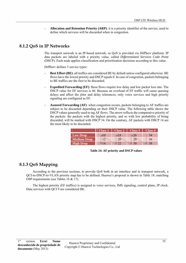
OSP LTE Wireless HLD
1st version Erro! Nome desconhecido de propriedade de documento (May 2013)
Huawei Proprietary and Confidential Copyright © Huawei Technologies Co., Ltd
55
- Allocation and Retention Priority (ARP): it is a priority identifier of the service, used to define which services will be discarded when in congestion.
8.1.2 QoS in IP Networks
The transport network is an IP-based network, so QoS is provided via DiffServ platform: IP data packets are labeled with a priority value, called Differentiated Services Code Point (DSCP). Each node applies classification and prioritization decisions according to this value.
DiffServ defines 3 service types:
- Best Effort (BE): all traffics are considered BE by default unless configured otherwise. BE flows have the lowest priority and DSCP equals 0. In case of congestion, packets belonging to BE traffics are the first to be discarded.
- Expedited Forwarding (EF): these flows require low delay and low packet loss rate. The DSCP value for EF services is 46. Because an overload of EF traffic will cause queuing delays and affect the jitter and delay tolerances, only voice services and high priority signaling are configured as EF.
- Assured Forwarding (AF): when congestion occurs, packets belonging to AF traffics are subject to be discarded depending on their DSCP value. The following table shows the DSCP values generally used to tag AF flows. The arrow reflects the comparative priority of the packets: the packets with the highest priority, and so with low probability of being discarded, will be marked with DSCP 34. On the contrary, AF packets with DSCP 14 are the most likely to be discarded.
Class 1 Class 2 Class 3 Class 4
Low Drop 10 18 26 34 Medium Drop 12 20 28 36 High Drop 14 22 30 38
Table 24: AF priority and DSCP values
8.1.3 QoS Mapping
According to the previous sections, to provide QoS both in air interface and in transport network, a QCI-to-DSCP-to-VLAN priority map has to be defined. Huawei’s proposal is shown in Table 18; matching OSP requirements (see Tables 16 & 17).
The highest priority (EF traffics) is assigned to voice services, IMS signaling, control plane, IP clock. Data services with QCI 9 are considered BE.
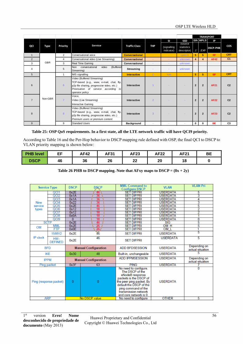
OSP LTE Wireless HLD
1st version Erro! Nome desconhecido de propriedade de documento (May 2013)
Huawei Proprietary and Confidential Copyright © Huawei Technologies Co., Ltd
56
Table 25: OSP QoS requirements. In a first state, all the LTE network traffic will have QCI9 priority.
According to Table 16 and the Per-Hop behavior to DSCP mapping rule defined with OSP, the final QCI to DSCP to VLAN priority mapping is shown below:
PHB level EF AF42 AF31 AF23 AF22 AF21 BE
DSCP 46 36 26 22 20 18 0
Table 26 PHB to DSCP mapping. Note that AFxy maps to DSCP = (8x + 2y)
SI SSD Eth MPLS IP
(signalling indicator)
(source statistics
descriptor) .1' .EXPDSCP‐PHB
1 2 Conversational voice Conversational - - speech 5 5 EF CRT
2 4 Conversational video (Live Streaming) Conversational - - unknown 4 4 AF42 C1
3 3 Real Time Gaming Conversational - - unknown
4 5Non conversational video (BufferedStreaming)
Streaming - - unknown
5 1 IMS signalling Interactive 1 Yes - 5 5 EF CRT
Video (Buffered Streaming)
TCP-based (e.g., www, e-mail, chat, ftp,p2p file sharing, progressive video, etc.) Priorisation of service according tooperator policy
Voice,
Video (Live Streaming)
Interactive Gaming
Video (Buffered Streaming)
TCP-based (e.g., www, e-mail, chat, ftp,p2p file sharing, progressive video, etc.)
Premium users or premium content
9 9 Standard Users Background - - - 0 0 BE C3
QCI Type Priority Service Traffic Class THP
GBR
Non-GBR
6 6 Interactive 1
8 8 Interactive 3
-
7 7 Interactive 2 - -
- -
COS
AF21
AF22
AF23
C2
C2
C2
-
TRANSPORT
2 2
2 2
2 2

OSP LTE Wireless HLD
1st version Erro! Nome desconhecido de propriedade de documento (May 2013)
Huawei Proprietary and Confidential Copyright © Huawei Technologies Co., Ltd
57
Table 27: Huawei’s Proposal on QCI-to-DSCP-to-VLAN priority mapping
8.1.4 Capacity and QoS
Compared to UMTS, LTE provides higher data rate speeds, i.e. the current capacity specification of the eNodeB is 450Mbps / 300Mbps (DL/UL), hence traditional transport methods such as E1 and PDH MW are not recommended. To achieve LTE target performance it is advisable to provide Ethernet interfaces (such as FTTN and PMW), providing speeds higher than 1Gbps.
In addition, the backhaul QoS requirement is far more stringent. Find the requirements in Table 18:
Table 28: QoS requirements for S1/X2 interfaces
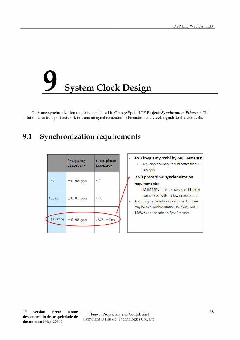
OSP LTE Wireless HLD
1st version Erro! Nome desconhecido de propriedade de documento (May 2013)
Huawei Proprietary and Confidential Copyright © Huawei Technologies Co., Ltd
58
9 System Clock Design
Only one synchronization mode is considered in Orange Spain LTE Project: Synchronous Ethernet. This solution uses transport network to transmit synchronization information and clock signals to the eNodeBs.
9.1 Synchronization requirements

OSP LTE Wireless HLD
1st version Erro! Nome desconhecido de propriedade de documento (May 2013)
Huawei Proprietary and Confidential Copyright © Huawei Technologies Co., Ltd
59
9.2 Synchronous Ethernet In Synchronous Ethernet (ITU-T G.8262), a network element extracts a reference clock from GPS, BITS or
directly from the transport link. The clock information is encoded at the physical layer of Ethernet and transmitted over the physical link to the Ethernet port of the eNodeB. Then, the Ethernet PHY chip in the eNodeB recovers the Ethernet packets and line clock from the modulated code streams and achieves synchronization.
In this case, the frequency precision target should be < +/- 4.6ppm.
Figure 44 Ethernet Synchronization
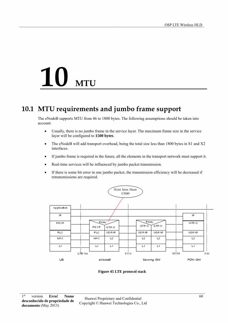
OSP LTE Wireless HLD
1st version Erro! Nome desconhecido de propriedade de documento (May 2013)
Huawei Proprietary and Confidential Copyright © Huawei Technologies Co., Ltd
60
10 MTU
10.1 MTU requirements and jumbo frame support The eNodeB supports MTU from 46 to 1800 bytes. The following assumptions should be taken into account:
Usually, there is no jumbo frame in the service layer. The maximum frame size in the service layer will be configured to 1500 bytes.
The eNodeB will add transport overhead, being the total size less than 1800 bytes in S1 and X2 interfaces.
If jumbo frame is required in the future, all the elements in the transport network must support it.
Real-time services will be influenced by jumbo packet transmission.
If there is some bit error in one jumbo packet, the transmission efficiency will be decreased if retransmissions are required.
Figure 45 LTE protocol stack

OSP LTE Wireless HLD
1st version Erro! Nome desconhecido de propriedade de documento (May 2013)
Huawei Proprietary and Confidential Copyright © Huawei Technologies Co., Ltd
61
11 Annex
A.1 Product descriptions