OsonE~hhE - apps.dtic.mil · ad-r148 215 evaluation of arctic test of improved tritium i/i...
75
AD-R148 215 EVALUATION OF ARCTIC TEST OF IMPROVED TRITIUM i/i RADIOLIJMINESCENT LIGHTING(U) OAK RIDGE NATIONAL LAB TN K W HAFF ET RL. AUG 84 AFESC/ESL-TR-84-i9 UNCLASSIFIED /G 1/5 NL OsonE~hhE
Transcript of OsonE~hhE - apps.dtic.mil · ad-r148 215 evaluation of arctic test of improved tritium i/i...
AD-R148 215 EVALUATION OF ARCTIC TEST OF IMPROVED TRITIUM i/iRADIOLIJMINESCENT LIGHTING(U) OAK RIDGE NATIONAL LAB TNK W HAFF ET RL. AUG 84 AFESC/ESL-TR-84-i9
UNCLASSIFIED /G 1/5 NL
OsonE~hhE
2.2.
Z.L.
125 1114i2 fl
J.L
ESL-TR-84-1 9
Evaluation of Arctic Test of ImprovedTritium Radioluminescent Lighting
K.W. HAFF, J.A. TOMPKINS, L.J. HULT, and C.L. Bup
OAK RIDGE NATIONAL LABORATORYPOST OFFICE BOX X
U OAK RIDGE, TENNESSEE 37031N
00AUGUST 1984
FINAL REPORTNOVEMBER 1083 - FEBRUARY 1984
iI( ECTE
D
jAPPROVED FOR PUBLIC RELEASE: DISTRIBUTION UNLIMITED1
x ENGINEERING & SERVICES LABORATORY_L" AIR FORCE ENGINEERING & SERVICES CENTERft~j TYNDALL AIR FORCE BASE, FLORIDA 32403
84 ii 28 001 =4
- - -5 ~ -q 84
NOTICE
PLEASE DO NOT REQUEST COPIES OF THIS REPORT FROM
*1. HQ AFESC/RD (ENGINEERING AND SERVICES LABORATORY).
ADDITIONAL COPIES MAY BE PURCHASED FROM:
NATIONAL TECHNICAL INFORMATION SERVICE
5285 PORT ROYAL ROAD
SPRINGFIELD, VIRGINIA 22161
FEDERAL GOVERNMENT AGENCIES AND THEIR CONTRACTORS
REGISTERED WITH DEFENSE TECHNICAL INFORMATION CENTER
SHOULD DIRECT REQUESTS FOR COPIES OF THIS REPORT TO:
DEFENSE TECHNICAL INFORMATION CENTER
CAMERON STATION
*ALEXANDRIA, VIRGINIA 22314
-,S . . . . .. * * * * ~ *- ' ' ' ' *' S 5 %
UNCLASSIFIED
SECURITY CLASSIFICATION OF THIS PAGE
REPORT DOCUMENTATION PAGE
a. REPORT SECURITY CLASSIFICATION lb. RESTRICTIVE MARKINGS
Unclassified
2a, SECURITY CLASSIFICATION AUTHORITY 3. DISTRIBUTION/AVAILABILITY OF REPORT
Approved for public release;2b. OECLASSIFICATION/DOWNGRADING SCHEDULE distribution unlimited
4. PERFORMING ORGANIZATION REPORT NUMBER(S) 5. MONITORING ORGANIZATION REPORT NUMBER(S)
ESL-TR-84-19
6.. NAME OF PERFORMING ORGANIZATION Pb. OFFICE SYMBOL 7. NAME OF MONITORING ORGANIZATION(If applicable) Air Force Engineering and Services Center
Oak Ridge National Laborator4 Engineering and Services Laboratory
Sc. ADDRESS (City. State and ZIP Code) 7b. ADDRESS (City. State and ZIP Code)
Post Office Box X Tyndall Air Force Base, Florida 32403Oak Ridge, Tennessee 37831
Is. NAME OF FUNDING/SPONSORING 8b. OFFICE SYMBOL 9. PROCUREMENT INSTRUMENT IDENTIFICATION NUMBERORGAN IZAT ION (1f applicable )
N84-34
I. ADDRESS (City. State and ZIP Code) 10. SOURCE OF FUNDING NOS.
PROGRAM PROJECT TASK WORK UNITELEMENT NO. NO. NO. NO.
11. TITLE (Include Security Cla",fication) Evaluation of Arctic 62601F 2673 00 34
Test of Tm rove di Tritliun R in],m 'lnpq_Pn_
12. PERSONAL AUTHOR(S)Lighting (UNC)
Haff. K.W. and Tompkins, J.A., ORNL. and Hult. L.J.. and IuDD. C.L.- USAF/AAC13a. TYPE OF REPORT 13b. TIME COVERED 14. DATE OF REPORT (Yr.. Mo.. Day) I1S. PAGE COUNT
Final FROM Nov 83 TO Feb 84 August 1984 6716. SUPPLEMENTARY NOTATION
The availability of this report is specified on reverse of front cover.
I?. COSATI CODES 18. SUBJECT TERMS (Continue on rewvrse if necesary and identify by blockt number)
FIELD GROUP SUB. GR. Tritium Radioisotope18 02 Radioluminescent Arctic Evaluation
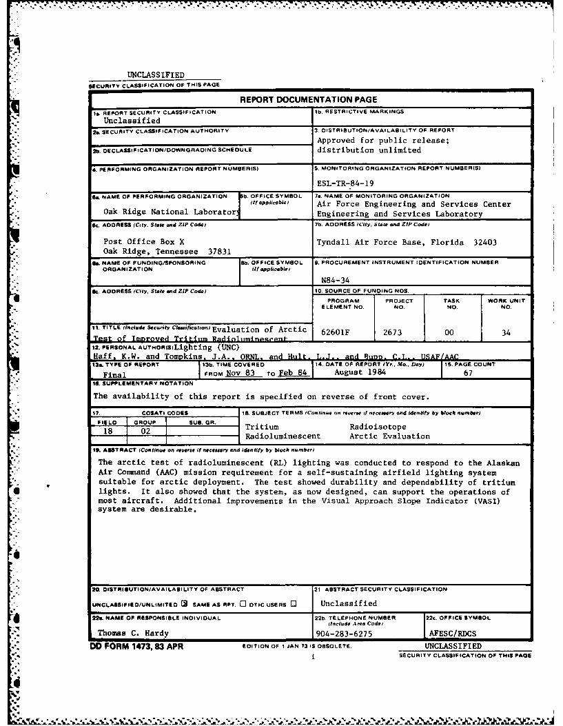
19. ABSTRACT (Continue on reVere if neceuary and identify by block, numbero
The arctic test of radioluminescent (RL) lighting was conducted to respond to the AlaskanAir Command (AAC) mission requirement for a self-sustaining airfield lighting systemsuitable for arctic deployment. The test showed durability and dependability of tritium
6lights. It also showed that the system, as now designed, can support the operations ofmost aircraft. Additional improvements in the Visual Approach Slope Indicator (VASI)system are desirable.
20. DISTRIBUTION/AVAILABILITY OF ABSTRACT 21. ABSTRACT SECURITY CLASSIFICATION
UNCLASSIFIED/UNLIMITED [R SAME AS RPT. C DTIC USERS 0 Unclassified
22.. NAME OF RESPONSIBLE INDIVIDUAL 22b TELEPHONE NUMBER 22c. OFFICE SYMBOL(Inclu de A rea CodeI
Thomas C. Hardy 904-283-6275 AFESC/RDCS
DD FORM 1473, 83 APR EDITION OF I JAN 73 IS OBSOLETE. UNCLASSIFIEDi SECURITY CLASSIFICATION OF THIS PAGE
d , , . -,,,"-,,,".- V -",. .. -:o",.," ": ,".'"' ". ' " ". "v " ..' ,-, ' ,, ' ,' ,- > '*. , - ,
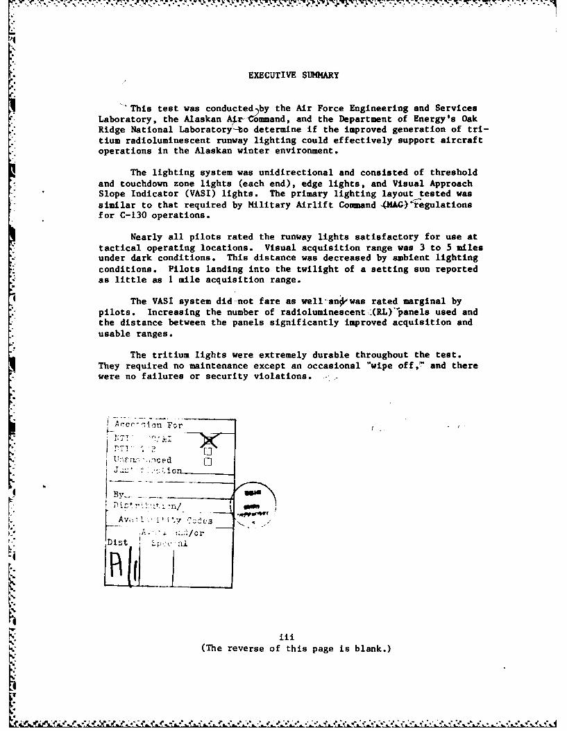
EXECUTIVE SUMMARY
This test was conducted by the Air Force Engineering and ServicesLaboratory, the Alaskan Air Command, and the Department of Energy's OakRidge National Laboratoryto determine if the improved generation of tri-
tium radioluminescent runway lighting could effectively support aircraft
operations in the Alaskan winter environment.
The lighting system was unidirectional and consisted of thresholdand touchdown zone lights (each end), edge lights, and Visual ApproachSlope Indicator (VASI) lights. The primary lighting layout tested was
similar to that required by Military Airlift Command (MAC)*regulationsfor C-130 operations.
Nearly all pilots rated the runway lights satisfactory for use attactical operating locations. Visual acquisition range was 3 to 5 milesunder dark conditions. This distance was decreased by ambient lighting
conditions. Pilots landing into the twilight of a setting sun reportedas little as I mile acquisition range.
The VASI system did not fare as well'anpwas rated marginal by
pilots. Increasing the number of radioluminescent (RL)'panels used andthe distance between the panels significantly improved acquisition andusable ranges.
The tritium lights were extremely durable throughout the test.They required no maintenance except an occasional "wipe off," and there
were no failures or security violations. -
Accr- _-Ion For
, --. ced
By-.
Av i i . ....
Dist
(The reverse of this page is blank.)
4, 6 w', C .. ' .'; .v 'J_', -,,' p " .,, ' ,, " ." ,e . . . . .,- , . .. € . ., -...- ,. . ...- , . , , .* ." .' .' ,, J.r
PREFACE
The work described in this report was performed by theRadioisotope Department, Operations Division, Oak Ridge NationalLaboratory, Post Office Box X, Oak Ridge, Tennessee, underInteragency Agreement 40-1127-80 for the Air Force Engineering andServices Center, Engineering and Services Laboratory (AFESC/RDCS),
Tyndall AFB, Florida, between 17 November 1983 and 15 December 1983.rhe AFESC/RDCS project officer was Thomas C. Hardy.
This document was prepared under the sponsorship of theAir Force. Neither the United States Government nor any personacting on behalf of the United States Government assumes any liabilityresulting from the use of the information contained in this document,or warrants that such use be free from privately owned rights.
This report has been reviewed by the Public Affairs Office (PA)and is releasable to the National Technical Information Service(NTIS). At NTIS, it will be available to the general public,including foreigr nationals.
This technical report has been reviewed and is approved forpublication.
THOMAS EVERETT L. MABRY LtCol USAFProjec 0 c Chief, nglneering R rch
UL M PE(OBIRTE. BOYER., 1, USAFSeni ,ienti t nd Director, Enqienq andChie , Air Ba urvivability Branch Services Laboraz
v
(The reverse of this page is blank.)
-* 00L
TABLE OF CONTENTS
Section Title Page
I INTRODUCTION ... .......... . . . . . . . . .. . . 1
II TEST PLAN, TEST PROCEDURE, AND EVALUATION PLAN . . . . . . 3
III TRITIUM RADIOLUMINESCENT LIGHT PANEL DESCRIPTION ..... 4
IV TI'b'i±L4. . . . . . . . . . . . . . . . . . . . 18
V DISCUSSION OF RESULTS .................. 20
VI CONCLUSIONS AND RECOMMENDATIONS ...... .. . . . 26
REFERENCES . ...................... . 28
Appendix
A EVALUATION OBJECTIVES .................. 29
B TEST PROCEDURE ...................... 33
C ARCTIC TEST EVALUATION PLAN ....... ... . . . . . 37
D SUMMARY OF ACQUISITION DISTANCES . . .......... 41
v
r-
0*Q
U 'o-.~-
*11 7777.777-7......* 7
LIST OF FIGURES
Figure Page
1 Radioluminescent Light Tube . . . . . . . . . . . . . . 5
2 Seven-Tube RLLight Pa. .. . ... .. .. . . .. 6
3 Rack for olding RL Light Panels . ... *. . . 7
4 Radioluminescent Runway Edge Light Fixture ... . 8
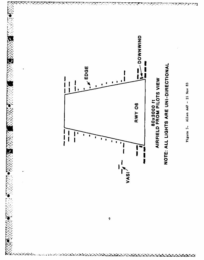
5 Allen AAF Layout -21 Nov 1983 . .. . . .... 9
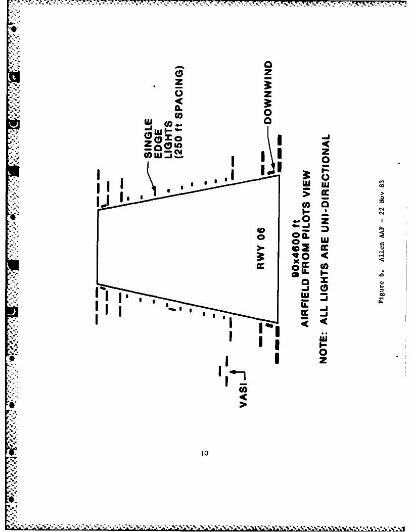
6 Allen AAF Layout -22 Nov 1983 . . ... .. 10
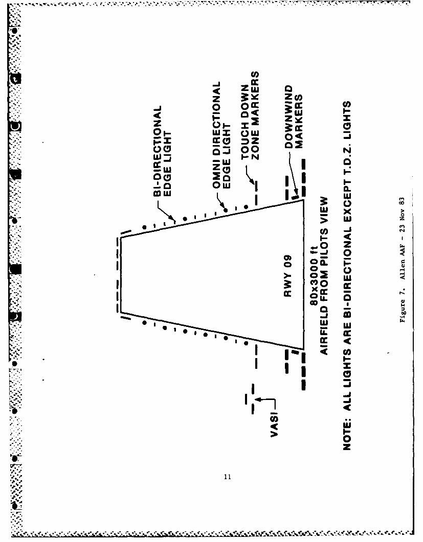
7 Allen AAF Layout -23 Nov 1983 . ... . .. 1
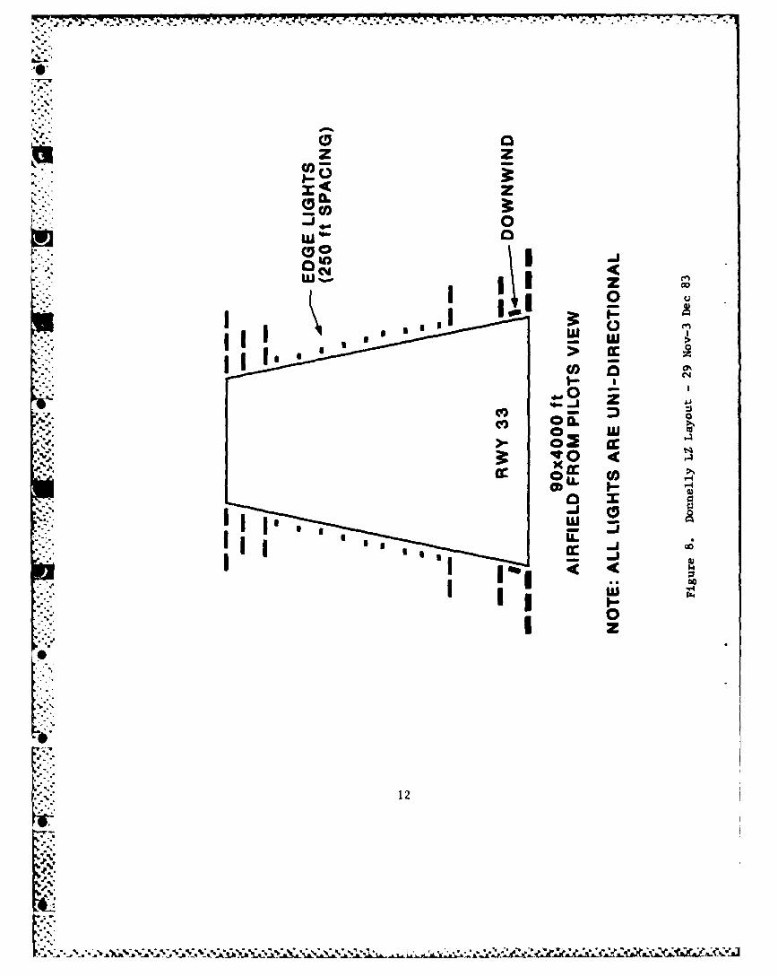
8 Donnelly LZ Layout -29 Nov - 3Dec 1983 . . . . . . . 12
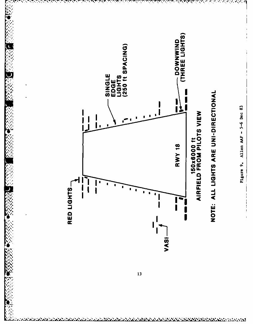
9 Allen AAF Layout -5-6 Dec 19 83 . . . . . . . . . 13
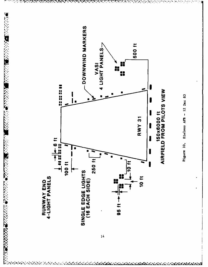
10 Eielson AFB Layout -12 Dec 1983 . . . . . . . 14
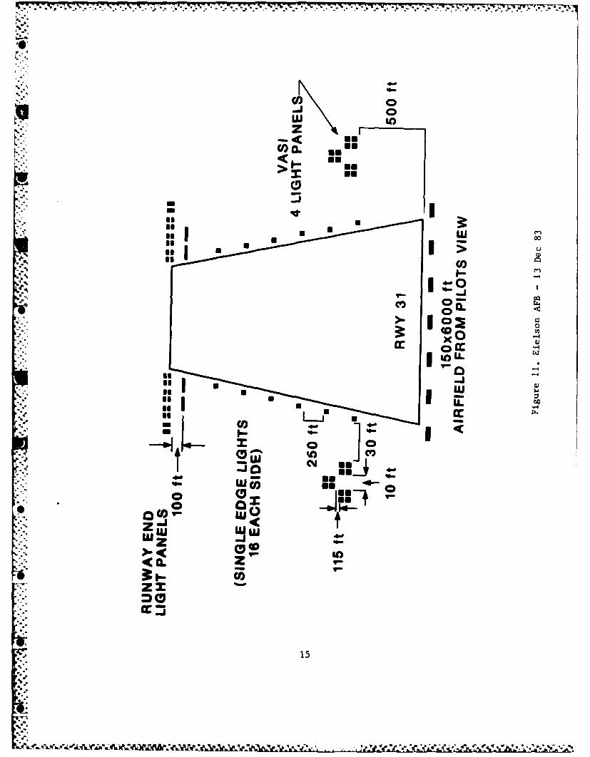
11 Eielson AFB Layout - 13 Dec 1983 . . . . . . . . . . . 15
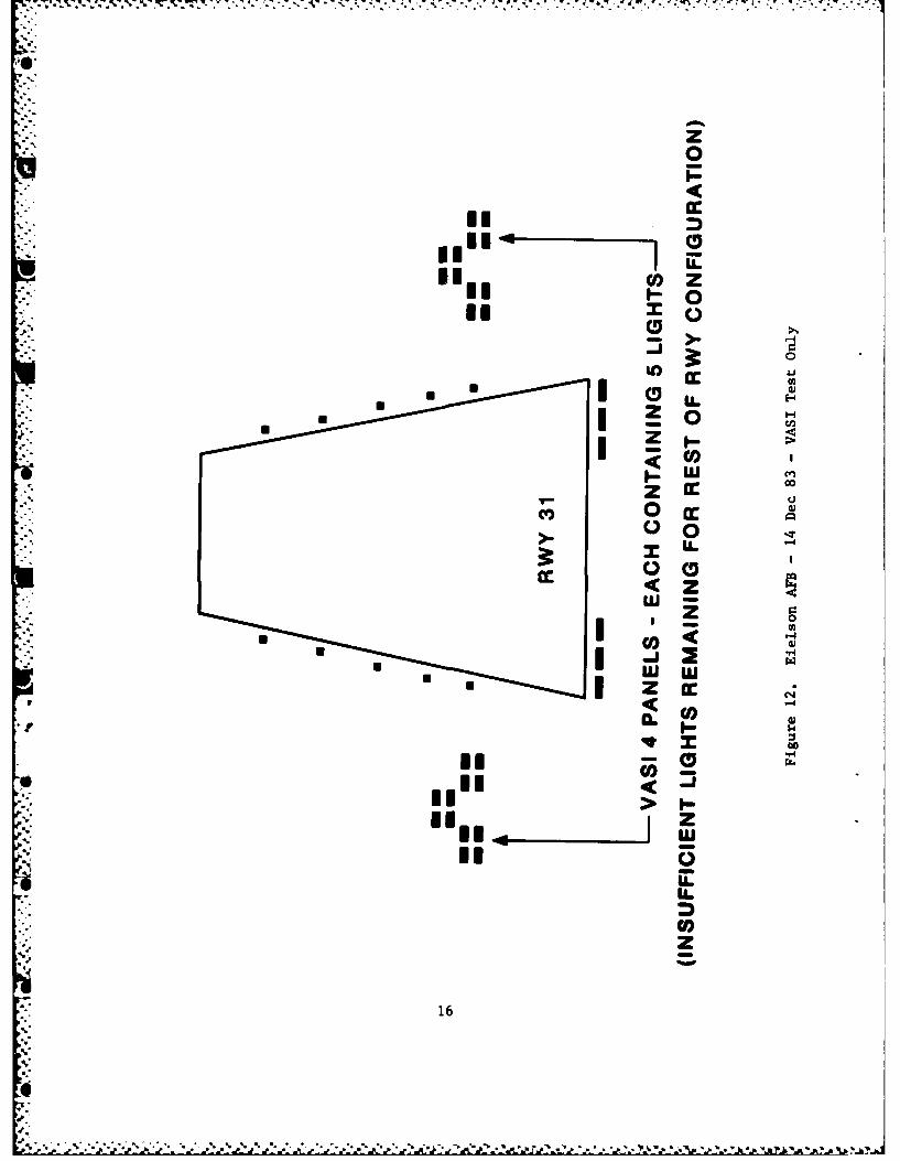
12 Eielson AFB Layout -14 Dec 1983 . . . . . . . . . . . 16
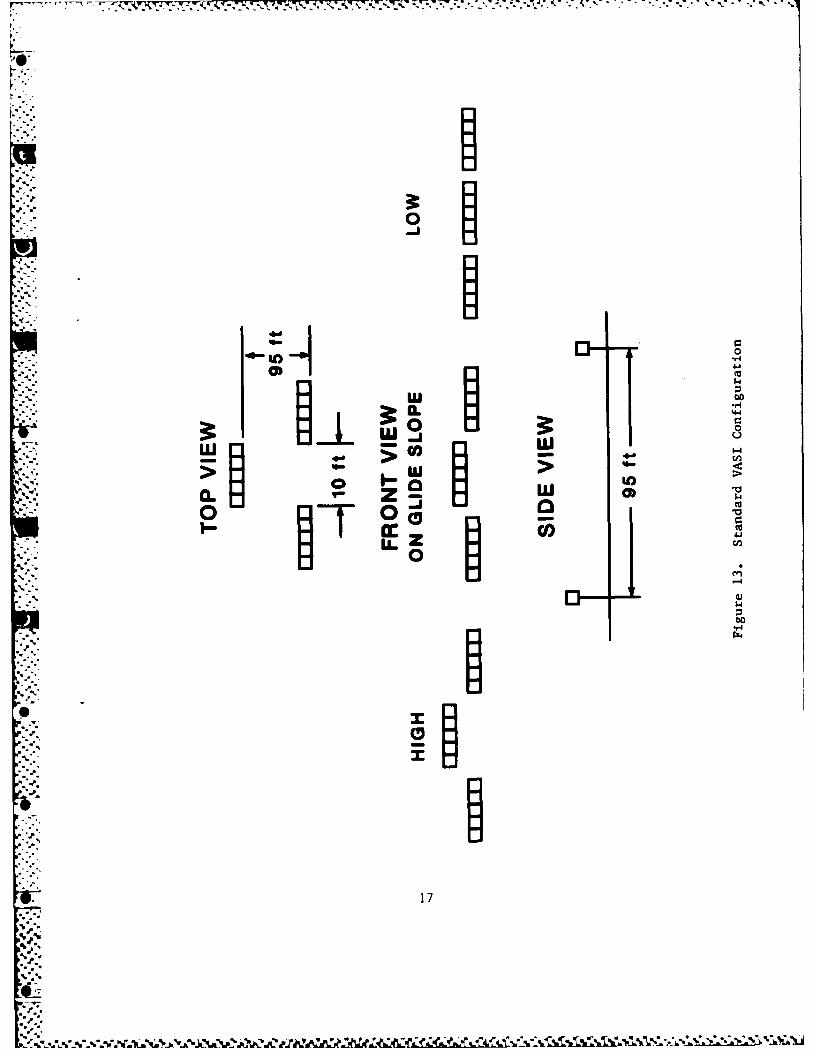
13 Standard VASI Configuration . . . . . . . . . . . . . 17
viii
9-..
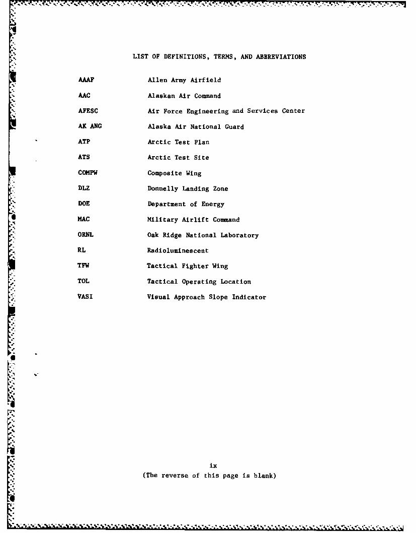
LIST OF DEFINITIONS, TERMS, AND ABBREVIATIONS
AAAF Allen Army Airfield
- AAC Alaskan Air Command
AFESC Air Force Engineering and Services Center
AK ANG Alaska Air National Guard
ATP Arctic Test Plan
ATS Arctic Test Site
COMPW Composite Wing
DLZ Donnelly Landing Zone
DOE Department of Energy
MAC Military Airlift Command.9
ORNL Oak Ridge National Laboratory
RL Radiolumines cent
TFW Tactical Fighter Wing
TOL Tactical Operating Location
VASI Visual Approach Slope Indicator
a,*.
.ix
(The reverse of this page is blank)
i,
a.a * . * w . . .." . . . . . . .
-
SECTION I
INTRODUCTION
Radioluminescent (RL) lighting is light produced by impingement of
radiation, generally a beta particle, into a phosphor. The light may be
visible or infrared (IR), depending on the phosphor selected. Radio-luminescent lighting has been used in industry for clock dials, exit
signs, and light standards in the photographic industry. Military appli-cations include light-emitting paints for aircraft dial illumination,
minefield markers, and gunsight illumination.
The Air Force is investigating alternate airfield lighting systems.
In addition to electric power costs, current airfield lights use incan-. descent bulbs which require frequent maintenance and replacement and
wiring systems which are expensive to install and also require main-
tenance. The use of tritium RL lighting should greatly reduce main-tenance costs. Mission planners desire a self-contained, lightweight
system for tactical bare-base employment which can be readily adapted to
permanent airfields during periods of contingency. Remote Arctic air
operations demand energy self-sufficient airfield lighting capable of
enduring severe environmental extremes.
"' In 1979 an Air Force suggestion was submitted by the 1776th Civil
Engineering Squadron, Andrews Air Force Base, Maryland, to construct run-
way distance and taxiway marker signs using the radioisotope tritium as a
power source. The proposal advocated the use of tritium-filled,phosphor-lined glass tubes instead of incandescent bulbs and electric
power for savings in airfield operation and maintenance costs.
A joint Department of Defense/Department of Energy (DOD/DOE) study
group was formed to develop applications for defense nuclear wasteradioisotopes as "alternate energy" lighting systems. This group, now
known as DOD/DOE RL Light Technical Working Group (TWG), has identified. many military applications. ORNL has designed, built, and demonstrated
the lights for many of these applications.
*O Tritium light fixtures were first demonstrated to the U.S. Air
Force (USAF) by DOE's Oak Ridge National Laboratory during a July 15-17,1980, demonstration at Andrews Air Force Base, Maryland. The demonstra-
tion was during night conditions, and some observers reported visual
sighting of up to I mile. However, more research was needed to improve
brightness, color quality, light distribution, and safety.
Subsequently, joint Department of Energy/Engineering and Services
Laboratory (DOE/ESL)-sponsored research at ORNL produced a report
entitled Testing of Tritium-Powered Runway Distance and Taxiway Markers.(1)
.JI
ORNL performed the initial evaluation tests on these RL signs, which
included the evaluation of illumination intensity, discoloration, tem-perature, thermal shock, pressure, impact, vibration, immersion, rough-handling, blowing-sand, and service-life tests.
The current program became known as PROJECT FIREFLY when tests ofan improved RL fixture were conducted by ORNL at Bogue Marine CorpsAuxiliary Landing Field (MCALF), North Carolina, on September 14-18,1981. These tests evaluated the product of joint DOE/ESL-sponsored RLdevelopments (2,3) and showed that the new fixture was at least twice (228percent as bright as the original prototypes. During August 9-12, 1982, opera-tional tests (OT&E) were performed at Bogue MCALF by ORNL to evaluate anew tritium light fixture geometry redesigned to provide a significantlygreater area of light emission. These lights were tested in the Arcticenvironment during January and February 1983.(4) While improved, furtherimprovement was required. The current tests described in this report areof an improved lighting system. The improved lights are observable atgreater than twice the distance of the previously tested lights.
The AAC has a continuing requirement for portable runway lightingto support exercise and operational commitments. TOLs for A-10, C-130,and other aircraft must be capable of 24-hour-a-day operations.Permanent airfields require a portable runway lighting system to back upinstalled lighting if failure should occur.
The arctic and subarctic environments of Alaska place specialdemands on runway lighting systems. Adverse weather conditions of pre-cipitation, wind, and extremely low temperatures occur year round andcause conventional lighting equipment breakdowns and frequent main-tenance. During the winter, there are few hours of daylight in which tomake repairs; and the cold weather hampers these efforts, or even makesthem unsafe. Additionally, replacement parts for currently used runwaylighting systems are often difficult to procure and have long deliverytimes.
The requirement for improved portable runway lighting has been for-mally identified in AAC Statement of Operational Need (SON) 1-84.
The primary goal of the Arctic Operational Test was to evaluate the*ability of RL lighting technology to satisfy the Alaskan Air Command
(HQ AAC) operational requirements. The secondary role of this test is toevaluate the feasibility of this lighting to reduce installation, opera-tion, and maintenance costs of airfield lighting systems. A completelist of evaluation objectives is described in Appendix A.
"S. ".2
!.
SECTION II
TEST PLAN, TEST PROCEDURE, AND EVALUATION PLAN
TEST PLAN
The Tritium Radioluminescent Lighting Arctic Test Plan was preparedand distributed by HQ, Air Force Engineering and Services Center (AFESC),Tyndall Air Force Base, Florida. This plan should be consulted for adetailed description of the tests, participants, test requirements,methodology, and responsibilities of participating organizations.
TEST PROCEDURE
The Test Procedure is taken from the Test Plan and is presented in
Appendix B.
EVALUATION PLAN
The Arctic Test Evaluation Plan is taken from the Test Plan and is
presented in Appendix C.
p.3
i..,.*. .4.' . .4.. 4 4. % V ~ ~
SECTION III
TRITIUM RADIOLUMINESCENT LIGHT PANEL DESCRIPTION
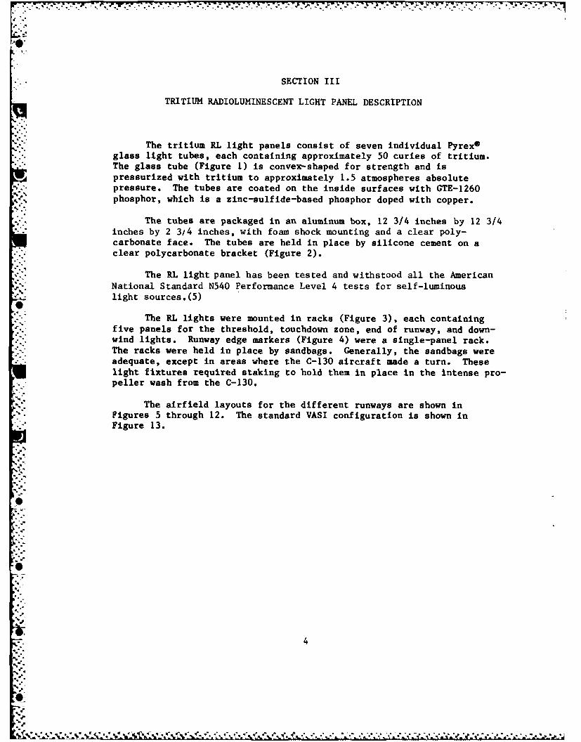
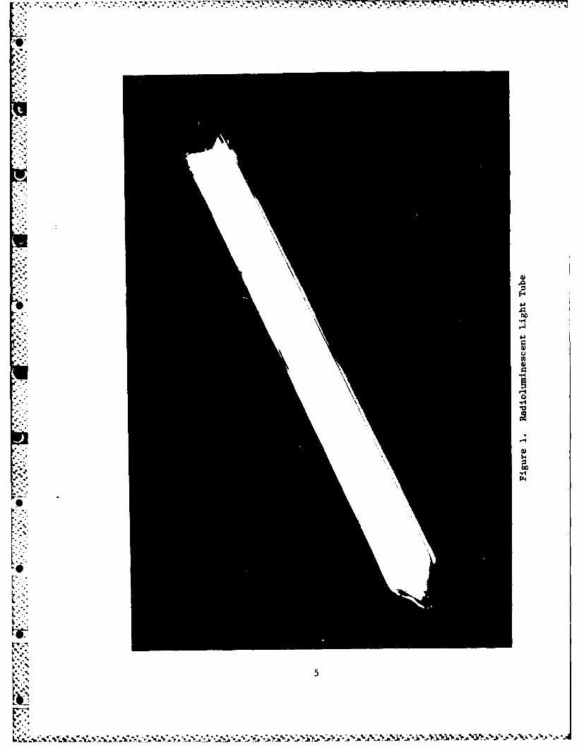
The tritium RL light panels consist of seven individual Pyrex ®glass light tubes, each containing approximately 50 curies of tritium.The glass tube (Figure 1) is convex-shaped for strength and is
Ipressurized with tritium to approximately 1.5 atmospheres absolutepressure. The tubes are coated on the inside surfaces with GTE-1260phosphor, which is a zinc-sulfide-based phosphor doped with copper.
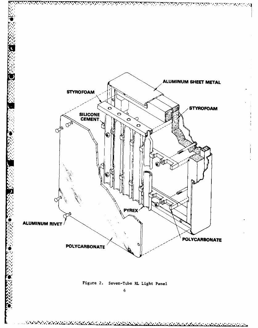
The tubes are packaged in an aluminum box, 12 3/4 inches by 12 3/4inches by 2 3/4 inches, with foam shock mounting and a clear poly-carbonate face. The tubes are held in place by silicone cement on aclear polycarbonate bracket (Figure 2).
The RL light panel has been tested and withstood all the AmericanNational Standard N540 Performance Level 4 tests for self-luminouslight sources.(5)
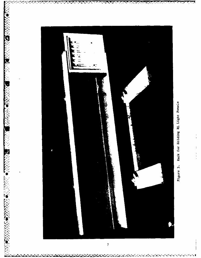
The RL lights were mounted in racks (Figure 3), each containing. five panels for the threshold, touchdown zone, end of runway, and down-
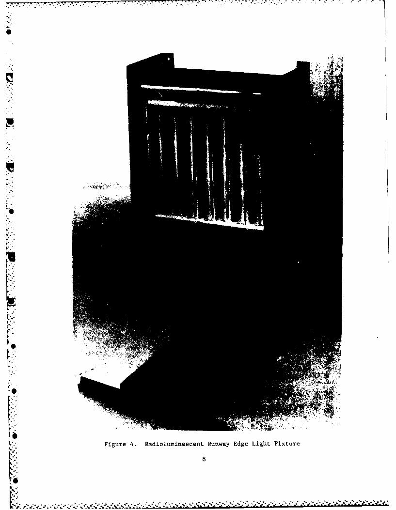
wind lights. Runway edge markers (Figure 4) were a single-panel rack.The racks were held in place by sandbags. Generally, the sandbags were
- adequate, except in areas where the C-130 aircraft made a turn. Theselight fixtures required staking to hold them in place in the intense pro-
.. peller wash from the C-130.
The airfield layouts for the different runways are shown in
Figures 5 through 12. The standard VASI configuration is shown inFigure 13.
4
.q..
.J
, . * . * '. * . -.°* *
S S *~.... - - . - S -
0
5~.
4).0
*00
*r4
0)C.)U)4)
*1*4
0.1-I
~1
4)I~4
00S.,. v4
S
LI.
L '
5
ALUMINUM SHEET METAL
SILICOANENA~
* P O L Y C A R B O N A T E
0 PLCRBNT
Figure 2. Seven-Tube RL Light Panel
6
00
"po
-4
0bo
r..
Figure 4. Radioluminescent Runway Edge Light Fixture
00
00
0.-
- U
3:CV 00
U..
co'
I~ui
Ii a
K 9
-W .- r '----------
5m z0. 0
L4 0 0
-j >.
MCo)
U . j
Sii
0
100
rZ U
z~ Zco
UJUJ
3 w 0
in ~0 00W I--i N
w cw
OC9O
co w w
I-JC
0 U0coz
'd* .'
- 1c
4 * ** * * y~ - ** cc
z- -
0j
CYC
z OD
00wISO
LUU
.0 x(:t. - K
4I( q(00
K 12
z~ -w
X0 00.'
oc
000
0-CO
00
00
000U 0
13
'U L
Co o
CC
do U)
CEL
K 0 0
* Co
4 4w0 t
C U) cm
TCo
6 14
g*~ UJ u
' I*j*~ *
(1) oLU LL
06
Cfa)CYo
z =J
CLL
z-J
15n4
z0
cc 00
I--I0'-4
ccI
x ~00
Cl0)rn0.
16~E-
0 0UU 0Li wI
C- w V
0 -H
17-
o- 7% 77-V a
SECTION IV
TESTING
On 17 November 1983, the lighting system departed McGhee-Tyson AFB
on an Alaskan Air National Guard C-130 transport, arriving at AAAF,Ft. Greely, Alaska, on 18 November 1983. The lights were inventoried,then stored and locked in the AAAF hangar. On 19 November 1983, the
lights were set up on Runway 09 for State of Alaska and Federal AviationAdministration flight testing. On 21 November 1983, the lights were set
up on Runway 06 (Figure 5). Prevailing weather conditions were: clearskies, strong winds, and full moon. Two 0-2 pilots flew low approachesbut could not land because of winds. The pilots acquired the lights at agreater distance on each succeeding approach. The VASI lights were notinstalled because of the strong winds.
The lights were again set up on Runway 06 on 22 November using the
configuration shown in Figure 6. Prevailing weather conditions were:partly cloudy skies and strong winds, and 0-2 pilots acquired five-panel
threshold lights at 4 to 5 miles and three-panel lights at 2 to 4 miles.Twenty-one TFW C-12 pilots flew numerous approaches and the pilot/
passengers acquired the lights at 4 miles minimum once they becameaccustomed to them. Both 0-2 and C-12 pilots made full-stop landingsusing the RL lights.
On 23 November 1983, the lights were deployed on Runway 06, as
shown in Figure 7. Prevailing weather was: complete cloud cover andsnow showers. An Alaskan ANG C-130 crew flew multiple approaches andlandings using the lights. Lights were acquired at 2 to 3 miles.
The weather (strong winds) prevented setting up the lights at theDLZ on 28 November 1983. However, they were deployed at DLZ on29 November (Figure 8). The VASI was not put up due to high winds.Between 30 November and 1 December i983, numerous C-130 sorties wereflown to DLZ to full-stop landings. Weather conditions varied;but winds, blowing snow, and cloudy conditions predominated. Mostaircraft turned onto final at 3 to 4 miles and the lights were normallyacquired at that time.
On 2 December 1983, flight operations were cancelled due to heavysnow and severely restricted visibility. On 3 December, the lights wereremoved from DLZ and placed in storage at AAAF.
The lights were again deployed at AAAF on 5 December 1983 onRunway 18 (Figure 9). Weather was scattered to broken clouds, with lighteasterly winds. The A-10 pilots made multiple low approaches but did not
land due to an icy runway. The first A-10 pilots flew approaches at aid-twilight (dusk), and they acquired the lights at only I to 1 1/2 miles.
18
,-

On 6 December, the same lighting conditions existed as on the previousnight. Weather was scattered to broken clouds with very strong, gustyeasterly winds. Six A-10 pilots flew multiple approaches but did notland due to the icy runway. Pilots' visual acquisition range variedbetween 2 and 3 miles.
During the period 12-14 December 1983, the lights were deployed onRunway 31 at Eielson AFB, Alaska. On 12 December (Figure 10) weather
conditions were clear and there was a half moon. The A-10 pilots flewlow approaches and made full-stop landings. On 13 December (Figure 11),
the configuration was changed based on pilot input and recommendations.The A-10 pilots again flew low approaches and made full-stop landings.
. On 14 December the lights were deployed as shown in Figure 12. Emphasis
was placed on VASI system improvement, which required increasing thenumber of lights. This did not allow full runway outline with theremaining lights. Approaches were made in a UH-I helicopter only, as no
. A-10s were scheduled to fly. Acquisition range with this configuration
was approximately 6 miles and usable range was 3 miles. Additionally,moon illuminiation was over one-half and peripheral airfield lighting was
-- .rated high.
0
-1*?,-?
0!
• oj19
; 9-,%;:.,. "-
w'
SECTION V4
DISCUSSION OF RESULTS
EASE OF STORING AND TRANSPORTING THE RL LIGHT PANELS AND FIXTURES
The tritium RL runway lighting system arrived at AAAF, Alaska,via C-130, loaded on two standard aircraft pallets. The pallets werebroken down by hand; and the lights, fixtures, bases, and support equip-ment were inventoried and loaded into trucks. The system was then takento the operations hangar and placed in secure storage. This entireoperation was accomplished in approximately 1 hour.
The lights were stored at AAAF in an unused room in the north wingof the hangar. While the lights were deployed to DLZ they were stored ina truck with a 14-foot long enclosed cargo box. This held all the RLlights and other equipment except the wood bases. The sandbags, whichwere used at both Allen and Donnelly, were the heaviest and most cumber-some part of the RL system to be stored or transported.
EASE AND SAFETY OF FIXTURE HANDLING WHILE WEARING ARCTIC CLOTHING
The clothing worn by test team personnel and installation crewsvaried with the weather and wind conditions each day. In severalinstances, full arctic gear (mukluk boots, "fat boy" pants, parka and
mittens) was required due to the below-zero temperatures and strong,gusty winds. Even with these restrictions, personnel had no problemshandling the RL lights, panels, and fixtures. Runway marking, lightsetup, positioning, and sandbagging/staking were all performed withoutremoval of mittens. The RL lights were also easily installed and removedfrom the fixtures by personnel wearing mittens.
Some fixture modifications, such as back-to-back panels forbidirectional testing, required the use of hand tools, such as pliers andscrewdrivers. In these cases, mittens had to be removed but created noadverse problems as most changes were done inside shelters.
.Q SUITABILITY AND ADAPTABILITY OF FIXTURE SUPPORTS FOR TEMPORARYINSTALLATION
The fixture supports were easy to install since they are relatively
lightweight and freestanding. The 2-inch by 6-inch wood bases were fairlystable and only needed anchoring. This was done by sandbagging and
4 staking. Freezing in place was not used, and the fixtures were doublesandbagged at AAAF and Eielson AFB. This method proved satisfactory,with the exception of the fixtures placed on the smooth surfaces at therunway ends. Several of these were skidded by air blasts from largeaircraft and required extra sandbags.
2
";20

At DLZ, the fixtures were both sandbagged and staked in place. The
stakes (10-inch spikes) prevented the fixtures from sliding caused by
propeller blast. Staking alone was not adequate because stakes could
only be driven less than 2 inches into the frozen ground. The com-bination sandbag and stake method of installation proved satisfactorybecause it was simple, quick, and easy.
A disadvantage was the requirement to either transport the heavy
sandbags or have some method of filling them on location. However, ifthe ground is not frozen, the stakes driven through the predrilled holeswould alone be satisfactory to hold the fixtures.
INSTALLATION AND REMOVAL TIME REQUIREMENTS
The typical installation sequence for installing the RL lightingsystem was:
a. A three-person crew measured and marked the runway for theappropriate lighting configuration. This was done with a measuring tape,a measuring wheel, and spray paint.
b. Fixture bases were positioned and sandbagged/staked as
necessary.
c. RL light panels were placed in the racks to complete thefixtures.
Under normal conditions, the three-person team can mark a 4000-foot
runway and install the lights in less than 2 hours. Conditions such ashigh winds extend the installation time or require additional personnel.Disassembly and removal time also took approximately 2 hours, depending
upon conditions.
MAINTAINABILITY, TO INCLUDE CLEANING THE PANELS AND FIXTURES
The RL lighting system required almost no maintenance and minimalupkeep. Several fixtures had to be realigned and sandbagged aftersliding several feet from aircraft blast. Although the RL lights werenot affected by temperature, they did collect a layer of dust from C-130
operations at DLZ and had to be wiped off daily. At Eielson AFB, a thin
layer of frost formed on the lights, and light scraping was required toremove this.
At AAAF, the vertical pipe on one fixture broke off from the base.It was not needed for the remaining tests but could easily have beenrepaired by welding or replacement. Also, several wooden bases became
loose where cross members were nailed together. This was remedied with ahammer and a few extra nails.
V 21
. .
.5 55.- .' -
ABILITY TO WITHSTAND WEATHER, PROPELLER, AND JET BLAST EFFECTS
The tritium RL runway lights, panels, and fixtures easily withstood
all winter conditions encountered during testing. This included tem-
peratures to -25*F, winds to 50 miles per hour, and blowing snow and
dust. A needed precaution was extra sandbagging on lights susceptible to
direct jet or propeller blast. On several occasions at DLZ, fixtureswere turned by C-130 propeller blasts; and, in one instance, several
panels were blown out of their fixtures. The lights sustained no damageand were immediately placed back in operation. The only physical damage
to these lights was chipping and peeling of the reflective tape around
the edge. The A-10 aircraft at Eielson AFB had no effect on the lights.
The VASI light system was much more affected by weather conditions.
At both AAAF and DLZ, it could not be installed for a portion of the
testing due to strong winds. The front panels were nearly 5 feet above
the ground and were supported by two pipes connected to the fixture base.
Strong, gusty winds whipped these panels, and no amount of sandbagging or
staking could have held them in place. Other types of support, such as
guide wires, were not available to be evaluated.
* PHYSICAL AND ENVIRONMENTAL SAFETY AND SECURITY REQUIREMENTS
Safety and security of the RL lights were primary concerns of the
test team during the project. The lights were inventoried each time they
were transported, installed, or removed. Installation personnel were
thoroughly briefed on the potential hazard of breaking a tritium tube
fixture and what to do if such an accident should happen. They were
instructed to handle and installed the RL lighting as they would a con-
ventional lighting set. Throughout the test no RL lights were damaged or
broken. This was in spite of multiple installments/removals at three
S-. separate airfields under adverse weather and wind conditions.
Security of the lights also was proven not to be a significant
problem. During the first few nights of testing, the lights were
retrieved and stored. But, when the lights were deployed to DLZ with the
concurrence of all parties, they were left continuously in place on the
airfield for over 72 hours. During this period with minimal security, no
lights were damaged, stolen, or tampered with. The consensus of opinion
was that no incidents occurred because the lights were part of a runway
environment and appeared to be powered by an external source.
One of the first things done in this project was to thoroughly
brief all personnel, including USAF installation team members, AAAFoperations staff, and flight service station personnel. The briefing
covered the purpose and sequence of the test and concentrated heavily on
the high value of the RL lights and the Federal laws which could be
violated if a light was stolen or intentionally vandalized.
Additionally, personnel were told that information about the test,
22
%
'
*- although not classified, should not be released or discussed with nontestteam personnel without permission. Finally, all personnel were requestedto assist with security by ensuring that unauthorized individuals werenot allowed access to the RL lights while installed or in storage.
Secure storage of the RL lights was easily provided. During thetesting at AAAF, a corner room in the main hangar was used. Both entrydoors were padlocked and the area was monitored by Army personnel.During other phases of testing, the lights were stored in a truck whichhad an enclosed lockable metal cargo box. The truck was always lockedand parked in a secure location. No security violations occurred duringany test phase.
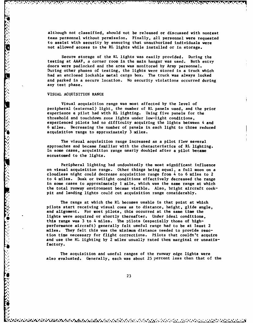
VISUAL ACQUISITION RANGE
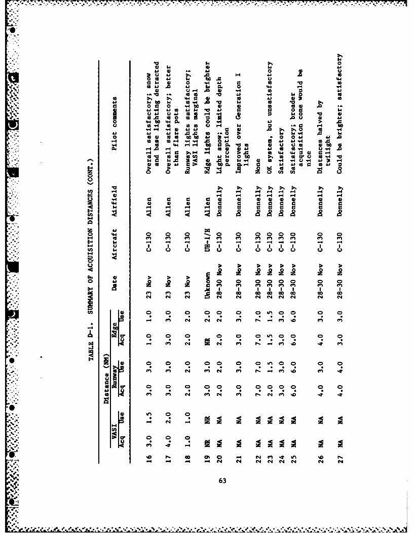
Visual acquisition range was most affected by the level ofperipheral (external) light, the number of RL panels used, and the priorexperience a pilot had with RL lighting. Using five panels for thethreshold and touchdown zone lights under low-light conditions,experienced pilots had no difficulty acquiring the lights between 4 and6 miles. Decreasing the number of panels in each light to three reducedacquisition range to approximately 3 miles.
The visual acquisition range increased as a pilot flew severalapproaches and became familiar with the characteristics of RL lighting.In some cases, acquisition range nearly doubled after a pilot becameaccustomed to the lights.
Peripheral lighting had undoubtedly the most significant influenceon visual acquisition range. Other things being equal, a full moon on acloudless night could decrease acquisition range from 4 to 6 miles to 2to 4 miles. Dusk or twilight conditions effectively decreased the rangein some cases to approximately I mile, which was the same range at whichthe total runway environment became visible. Also, bright aircraft cock-pit and landing lights could cut acquisition range considerably.
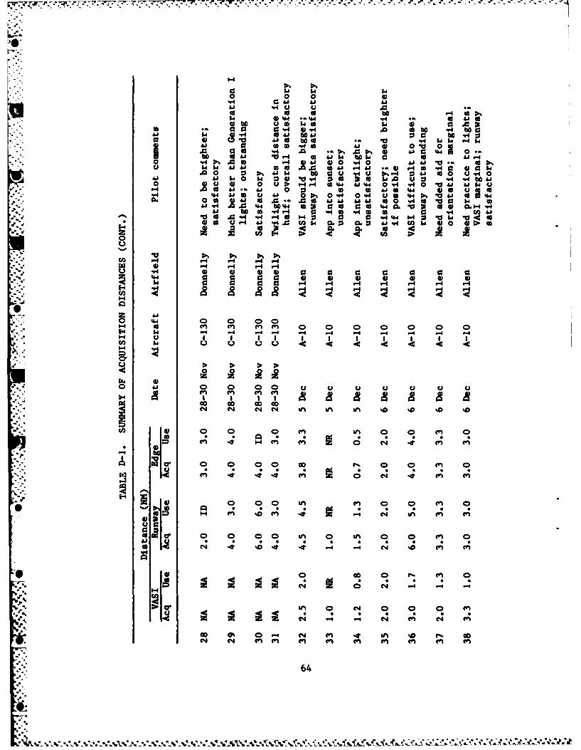
The range at which the RL becomes usable is that point at whichpilots start receiving visual cues as to distance, height, glide angle,and alignment. For most pilots, this occurred at the same time thelights were acquired or shortly thereafter. Under ideal conditions,
oS this range was 3 to 4 miles. The pilots (especially those of high-performance aircraft) generally felt useful range had to be at least 2miles. They felt this was the minimum distance needed to provide reac-tion time necessary for flight corrections. Pilots that couldn't acquireand use the RL lighting by 2 miles usually rated them marginal or unsatis-factory.
The acquisition and useful ranges of the runway edge lights werealso evaluated. Generally, each was about 25 percent less than that of the
23
'2
threshold and touchdown zone lighting. Initially, the test team did notconsider edge light acquisition a critical factor; however, pilotdebriefings showed this to be untrue. The edge lights aided the pilotsin connecting the runway ends, thereby improving depth perception andproper glide-path determination.
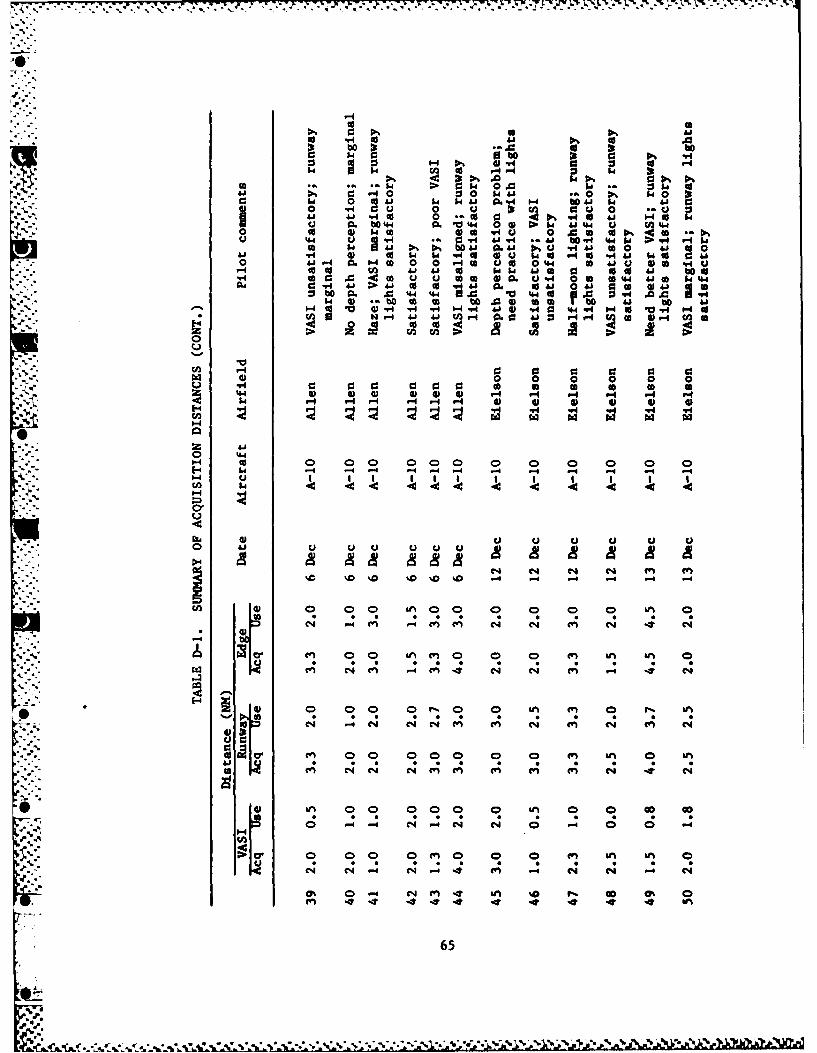
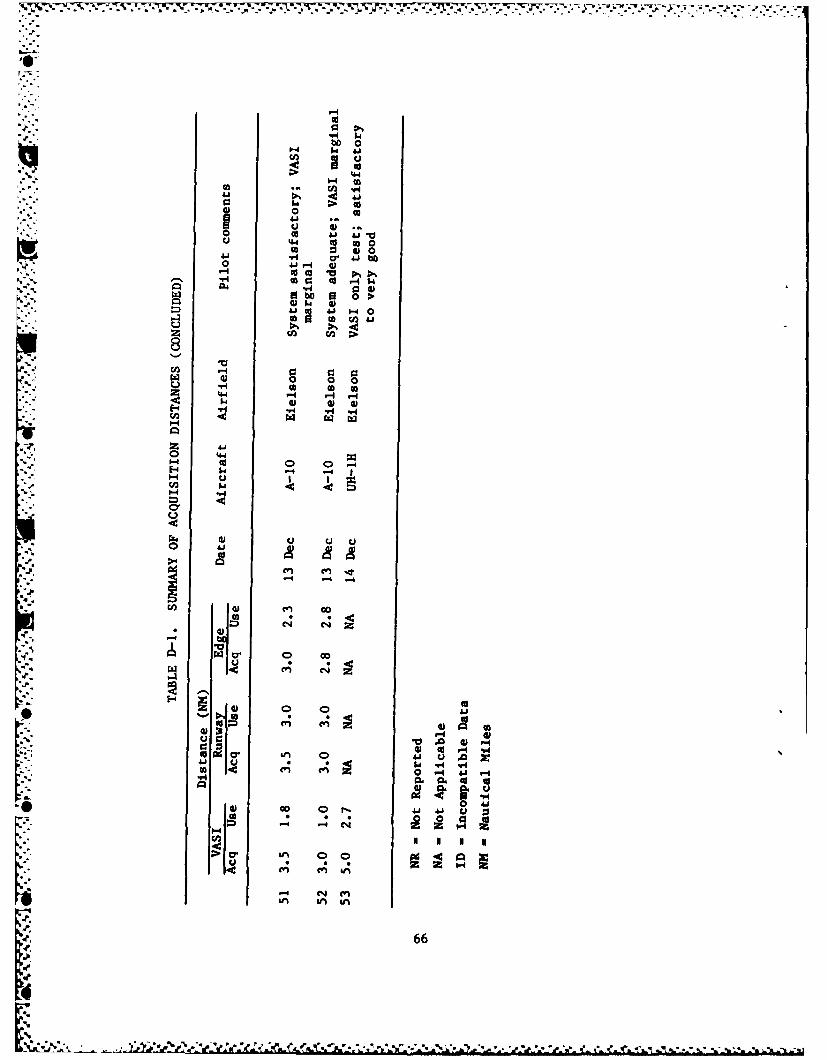
A summary of the reported distances, as reported by pilots and non-pilot observers, taken from the questionnaires is presented in Appendix D.
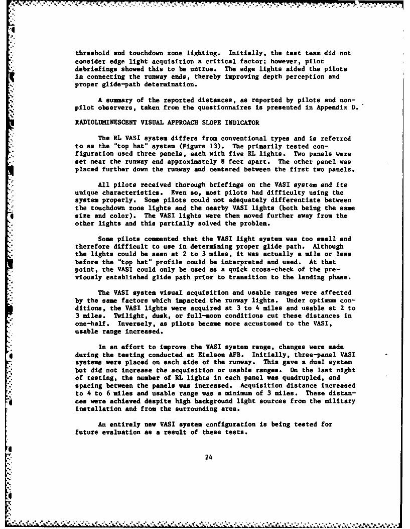
RADIOLUMINESCENT VISUAL APPROACH SLOPE INDICATOR
The RL VASI system differs from conventional types and is referredto as the "top hat" system (Figure 13). The primarily tested con-figuration used three panels, each with five RL lights. Two panels wereset near the runway end approximately 8 feet apart. The other panel wasplaced further down the runway and centered between the first two panels.
All pilots received thorough briefings on the VASI system and itsunique characteristics. Even so, most pilots bad difficulty using thesystem properly. Some pilots could not adequately differentiate betweenthe touchdown zone lights and the nearby VASI lights (both being the samesize and color). The VASI lights were then moved further away from theother lights and this partially solved the problem.
Some pilots commented that the VASI light system was too small andtherefore difficult to use in determining proper glide path. Althoughthe lights could be seen at 2 to 3 miles, it was actually a mile or lessbefore the "top hat" profile could be interpreted and used. At thatpoint, the VASI could only be used as a quick cross-check of the pre-viously established glide path prior to transition to the landing phase.
The VASI system visual acquisition and usable ranges were affectedby the same factors which impacted the runway lights. Under optimum con-ditions, the VASI lights were acquired at 3 to 4 miles and usable at 2 to3 miles. Twilight, dusk, or full-moon conditions cut these distances inone-half. Inversely, as pilots became more accustomed to the VASI,usable range increased.
In an effort to improve the VASI system range, changes were madeduring the testing conducted at Eielson AFB. Initially, three-panel VASIsystem were placed on each side of the runway. This gave a dual systembut did not increase the acquisition or usable ranges. On the last nightof testing, the number of RL lights in each panel was quadrupled, andspacing between the panels was increased. Acquisition distance increasedto 4 to 6 miles and usable range was a minimum of 3 miles. These distan-ces were achieved despite high background light sources from the militaryinstallation and from the surrounding area.
An entirely new VASI system configuration is being tested forfuture evaluation as a result of these tests.
24
-U,
OVERALL ADEQUACY OF TRITIUM RL LIGHTING
The improved tritium RL runway lighting system tested in thisperiod was significantly improved over the previously tested lights.Pilots flying smaller, slower-moving aircraft, such as the 0-2 and C-12,rated the first-generation lights "satisfactory" for remote tacticaloperating locations. In contrast, the present lighting system was rated"excellent" to "outstanding" by pilots flying these same aircraft.Pilots of larger aircraft, like the C-130, rated the first-generationlights "marginal," while rating the new lights "satisfactory." A numberof pilots participated in both tests and indicated the new system was asignificant improvement over both the first-generation lights andbattery-powered lights.
The results of the VASI system were less spectacular. In bothtests they were rated overall "marginal." Only during the last day oftesting when the number of RL lights was increased did pilots considerthe VASI "satisfactory."
25
°771
SECTION VI
CONCLUSIONS AND RECOMMENDATIONS
CONCLUSIONS
This test showed the durability, dependability, and safety of thetritium RL lights. It also showed that runway threshold, touchdown zone,and edge lights were satisfactory in defining the runway environment.This system is entirely adequate for use at a remote tactical operatinglocation where competing external ground lighting is minimized. Thethree-panel VASI system was marginal, and further change and testing arerequired before it can be considered acceptable. The tritium RL lightingis not a navigational aid. Other systems must be utilized for areaorientation and initial alignment to the runway - these could easily bean inertial navigation system, TACAN, ground radar, strobe lights, orrotating beacons. This fact does not detract from the usefulness orapplicability of the tritium RL runway lighting system.
GENERAL RECOMMENDATIONS
a. Pilots should complete at least one training sortie, flyingmultiple approaches to the RL lights, prior to using operationally.
b. A method should be developed to cover the lights in caseblackout conditions are required*
c. The size of the runway edge lights should be doubled (twopanels instead of one) and installed every 500 feet and evaluated.
e. The size and configuration of the VASI system should beexamined to develop a more usable system.
f. An improved method of supporting the VASI lights needs to bedesigned so that they can be used in strong and gusty wind conditions.
*I RECOMMENDATIONS BY PILOTS
Participating pilots made a number of coments and suggestions forimprovement of the tritium RL lights. Some of the most common are listedbelow, in no particular order.
a. Because the RL lights are different, pilots should receiveflight training prior to operational use.
b. The VASI system should be larger and should be furtherseparated from the runway lights.
26

c. The edge lights could be larger.
d. Additional aids, such as strobe lights or rotating beacons, areneeded to help find the airfield.
e. Some method should be found to extinguish or cover the lightswhen airfield blackout conditions require it.
f. Navy-style meatball-type lights are needed.
g. Lights could be larger and brighter.
h. Keeping cockpit lights low and landing lights off until shortfinal could greatly improve usability.
i. Omnidirectional capability would be useful.
j. In A-10 aircraft, looking over the heads-up display (HUD) wouldimprove acquisition range.
k. External light from the sun (twilight/dusk) or incandescentfixtures cut acquisition range in one-half.
1. The RL lights are satisfactory for remote tactical operatinglocations.
m. Depth-perception problems occur because the RL lights aredifferent.
n. VASI system was marginal and could not be used under opera-tional conditions.
o. The lights were very easy to use once the user becameaccustomed to them.
p. Red panels at the end of the runway might be beneficial.
q. Snow showers redi'ce the acquisition range considerably.
I r. The lights were difficult to see at dusk.
s. The lights were better than bean-bag lights.
t. The only problem wtthsyemashemarginal VASI.
r2
1 27
',
• -c'hIdelghscudb agr
4 .Adtoa is uha tob ihso oaigbaos r
REFERENCES
1. Haff, K. W., Case, F. N., Schultz, F. J., and Tompkins, J. A.,Testing of Tritium-Powered Runway Distance and Taxiway Markers,Air Force Engineering and Services Center, ESL-TR-81-45, August 1981.
2. Case, F. N., Haff, K. W., Krypton-85 Powered Lights for AirfieldApplication, Air Force Engineering and Services Center, ESL-TR-80-55,November 1981.
3. Case, F. N., Haff, K. W., Tompkins, J. A., Schultz, F. J., and. Remini, W. C., Radioisotope Powered Light Sources, Air Force
Engineering and Services Center, ESL-TR-82-12, April 1982.
- 4. Haff, K. W., Tompkins, J. A., and Case, F. N., Evaluation of Arctic
-' 'i Test of Tritium Radioluminescent Lighting, Air Force Engineering and
Services Center, ESL-TR-83-35, August 1983.
- _. 5. American National Standard N540, Classification of RadioioactiveSelf-Luminous Light Sources, NIBS Handbook 116, U.S. Department ofCommerce, National Bureau of Standards, 1976.
W 28
-.
_..
... %'-'i-* % *,'.. . . . -C
-
"O"
APPENDIX A
EVALUATION OBJECTIVES
'-.2
.%
. "°b..~
APPENDIX A
EVALUATION OBJECTIVES
In an effort to overcome the limitations of currently used runwaylighting and provide improved support for air operations, the tritium RL
runway lighting was developed and tested. The following evaluationobjectives were extracted from the AFESC developmental test plan.
1. Engineering:
a. Ease of storing and transporting the RL lights and fixtures.
b. Ease and safety of fixture handling while encumbered with
arctic clothing.
c. Suitability and adaptability of fixture supports for tem-
porary installation.
d. Installation and removal time requirements.
e. Maintainability, to include cleaning lights and fixtures.
f. Ability to stand up to weather, propeller, and jet blast
effects.
2. Security and Safety:
a. Evaluate the physical and environmental safety and security
requirements of RL lighting.
b. Evaluate security precautions to preclude theft and/or
destruction.
3. Operational:
0 a. Identify and evaluate visual range at which pilots acquire
and can use the RL runway lighting. Acquisition range should be at least4 to 6 miles under ideal conditions.
b. Evaluate the capability of the RL VASI system to provide
usable glide-slope information.
c. Evaluate pilot views and comments on the RL lighting as an
aid for approach, landing, rollout and takeoff.
30
"[-V .'' o.2 . ."" '.' "°.. . ¢ ° ' ' .'¢ - ° ' % • - ' ° ' ' ' 2" ' " " "" " " . .
Mr;, 4 , . . ..-' - . . . . -.. -.., *J~, ,L - ,-- - - , , ,l i ., , 1 -. : . ro %, ,- ... .
d. Assess overall adequacy of the RL lighting to support a
variety of aircraft and operations in an arctic and subarctic environ-ment.
e. Provide individual and/or group recommendations to enhanceany aspect of RL light utilization.
'.4
•t -
."
S-
S." 31(The reverse of this page is blank)

APPENDIX B
TEST PROCEDURE
33
C ** r N: ....

07
APPENDIX B
TEST PROCEDURE
1. Each organization or agency participating in the Tritium Runway
Lighting Test will appoint a project officer or point of contact forscheduling briefing and coordination.
2. Organizations and aircraft which will be directed or invited toparticipate are as follows:
a. 21 TFW/C-12
b. 343 COHPW/0-2, A-10
c. 616 MAG/C-130
d. 176 TAG/C-130
e. 222 Av Bn/C-12, UH-1
. f. USCG/C-130
g. State of Alaska/Unknown
h. Federal Aviation Administration/Unknown
i. Other civilian agencies/Aircraft
3. To gain maximum participation from each organization, flexi-bility in scheduling each test period will be maintained.
4. Aircraft will be scheduled to fly during a specific time block
during each test period on the days of 19-22 November 1983.
5. Pilots using IFR flight plans may execute an instrumentapproach or may cancel the clearance and proceed VFR.
6. Pilots will thoroughly familiarize themselves with terrainsurrounding AAAF and the layout of the airfield and runway.
7. The primary runway for testing the lighting at AAAF is antici-pated to be Runway 18. Runway 18 is 7499 feet long and 150 feet wide.Depending upon tritium lights available, only 5000 or 6000 feet will belighted. Runways 36, 06, and 24 may be used if conditions warrant.
8. Prior to their flights, pilots will receive a thorough briefingon the runway in use, lighting configuration, radio frequencies, andother pertinent information.
34
t:
= J -.. . - o -'
9. The pilot will contact the test team on the specified radio fre--quency as soon as possible. At that time, he will receive an additional
briefing on current status of lights, weather conditions, and runway con-dition reading (RCR) or latest reported braking action.
10. Pilots will align the aircraft on the extended runway center-line, at least 5 miles from the threshold. This may be accomplishedvisually or by use of TACAN DME information.
11. Pilots will, as accurately as possible, document the maximum
distance at which the lights are acquired and the distance the lights*become usable for runway alignment and/or glide path information. TACAN
DHE will be noted if used for measurement.
12. If weather conditions permit, the pilot will execute a lowapproach and return to the final approach for a second view of the testlighting. Pilots may subsequently land or execute additional lowapproaches. At least one full-stop landing is requested. Pilots willprovide comments to the test team while on the ground.
13. Civilian pilots may make low approaches. Full-stop landings areauthorized if U.S. Army/civilian use requirements are met.
14. Pilots will complete the handout questionnaire and submit to theunit project officer or mail to HQ AAC/DOOS, Elmendorf AFB, AK 99506.
15. Engineers and/or ground support crews will also completequestionnaires and submit to the project officer or mail to HQ AAC/DEM,Elmendorf AFB, AK 99506.
I.
35(The reverse of this page is blank)
.71
APPENDIX C
ARCTIC TEST EVALUATION PLAN
37
*~~J two ~.,
- -• . . . . . . . . . - - -. . .- - . . . - . . .
APPENDIX C
ARCTIC TEST EVALUATION PLAN
INTRODUCTION
Subjective analysis of ground observations and aircrew question-
naires shall be the primary methods of data collection. The approved
tritium light questionnaire (ANNEX IV) shall be briefed and distributedto participating flying organizations by HQ AAC/DOOS. Members of the
team shall interview Priwae BEEF and other ATS support personnel to deter-mine the success of ground operations. At the conclusion of the exer-
cise, HQ AAC/ADO shall make a written assessment of the overalloperational acceptability of the RL lighting system under arctic opera-
tions. The Engineering Services Laboratory (ESL), Tyndall AFB, and ORNLshall observe the critique to document the results and recommendations inthe final technical report.
METHODORNL shall perform all data reduction and analysis to document test
results in the final technical report period.
Part I - Visual Evaluation: Questionnaires shall be distributed to
aircrew and ground observers as they in-process the exercise and during
daily preflight briefings. The observers will receive an explanation ofthe purpose of the test. The questionnaires can be returned by self-
addressed mail to HQ AAC/DOOS. Those received by the end of the exercise
shall be reviewed.
Part II - Physical Evaluation: ORNL shall collect, analyze, and
condense the test teams' observations, photographs, and witness inter-views at the ATS. Preliminary findings shall be briefed and presented inthe final reports.
EVALUATION OBJECTIVES
See Appendix A
DATA COLLECTION
The evaluation objectives shall be evaluated from the following
sources collected by AAC and the RL test team.
1. Aircrew questionnaires
2. Ground and airborne observations
,.3
, 38
."
q7
S..3. Individual interviews
4. Mission debriefings
5. Exercise critique
6. Evaluation board
7. Photographic aids
* ANALYSIS
The final report shall contain the RL airfield lighting's actualsystem performance under arctic conditions as determined by expert obser-vers and other data-collection techniques. A discussion shall explainthe final fixture designs, fabrication techniques, expedient installationmethods, project costs, shipment limitations, and final erectionproblems.
CONCLUSIONS/RECOMMENDATIONS
Proposed future applications, further R&D, and project economic andoperational benefits shall be delineated as an overall assessment of theArctic Development Test. All conclusions and recommendations shall be
substantiated by this analysis.
DOCUMENTATION
ORNL shall prepare the final technical report. The final technicalreport shall be written in acordance with ESL-HB-84-01. Approvingauthority will be AFESC/RDCS. Reproducible original will be "camera-ready" copy, reference MIL-STD-847B. Report shall be published as ajoint AFESC/DOE technical report.
39(The reverse of this page is blank)
*. %-
=V
-44
APPENDIX C
..
| BRIEFING HANDOUT ON TRITIUM RADIOLUINESCENT
7 PORTABLE LIGHTING
,1
-
'" 41
1%
aI
.4.

APPENDIX C
ANNEX I
BRIEFING HANDOUT ON TRITIUM RADIOLUMINESCENTPORTABLE LIGHTING
BACKGROUND
RL lighting is defined as the use of radiation from radioisotopes incombination with phosphors to produce visible light. Radioluminescentlighting has been used in industry for clock dials, exit signs, and lightstandards in the photographic industry. The military has used light-emitting paints for aircraft dial illumination, minefield markers, andgunsight illumination.
Within the last several years, a joint DOE/DOE effort has been underway to develop tritium RL lighting for airfield application. A firstgeneration of tritium lighting was evaluated at Clear Creek LZ duringBRIM FROST 83. These lights proved to have a visual acquisition range ofI to 2 miles, which was suitable only for slow-moving aircraft.
Since then, comprehensive engineering efforts have produced a sig-nificantly improved runway light. It is anticipated that this light canbe acquired by aircrews between 4 to 6 miles, which is suitable to sup-port C-130/A-IO type aircraft operations.
Certain known techniques may be used by participating pilots toimprove acquisition of the lights, such as keeping cockpit/cabin lightingto an absolute minimum and not staring at the tritium lights; viewingslightly to the side may improve acquisition. It is also helpful not toturn on landing lights until short final as they tend to wash out thetest lights.
One final reminder: tritium lights are not incandescent. They giveoff a smooth glow rather than a bright-point light. Attached are spe-cific procedures to following during the test and a questionnaire to becompleted.
42

APPENDIX C
ANNEX II
PROCEDURES FOR A-10 EVALUATIONOF TRITIUM RADIOLUMINESCENT LIGHTS
-43
APPENDIX C
ANNEX II
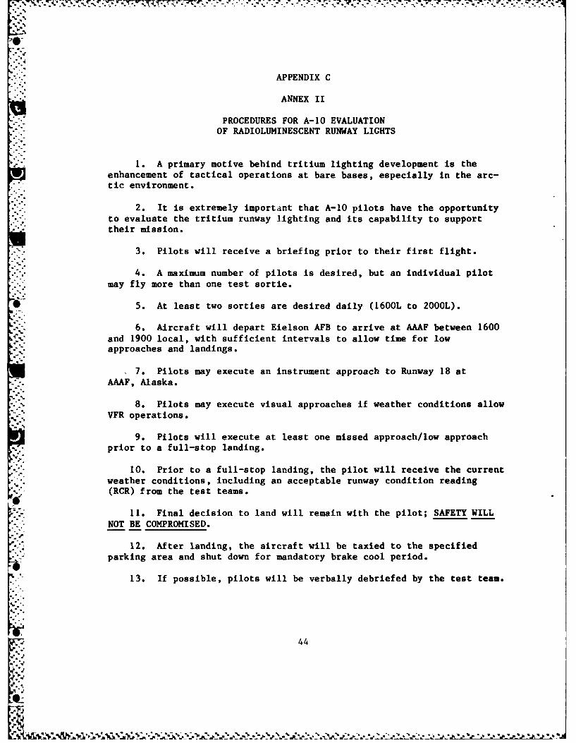
PROCEDURES FOR A-10 EVALUATION
OF RADIOLUMINESCENT RUNWAY LIGHTS
1. A primary motive behind tritium lighting development is the
enhancement of tactical operations at bare bases, especially in the arc-tic environment.
2. It is extremely important that A-10 pilots have the opportunity
"- to evaluate the tritium runway lighting and its capability to support' their mission.
3. Pilots will receive a briefing prior to their first flight.
4. A maximum number of pilots is desired, but an individual pilot
may fly more than one test sortie.
,' 5. At least two sorties are desired daily (1600L to 2000L).
6. Aircraft will depart Eielson AFB to arrive at AAAF between 1600
and 1900 local, with sufficient intervals to allow time for lowapproaches and landings.
7. Pilots may execute an instrument approach to Runway 18 at
AAAF, Alaska.
.' 8. Pilots may execute visual approaches if weather conditions allow
VFR operations.
9. Pilots will execute at least one missed approach/low approach* prior to a full-stop landing.
10. Prior to a full-stop landing, the pilot will receive the currentweather conditions, including an acceptable runway condition reading
*. (RCR) from the test teams.
11. Final decision to land will remain with the pilot; SAFETY WILL
NOT BE COMPROMISED.
12. After landing, the aircraft will be taxied to the specifiedparking area and shut down for mandatory brake cool period.
13. If possible, pilots will be verbally debriefed by the test team.
44
APPENDIX C
ANNEX III
* PROCEDURES FOR C-130 EVALUATIONOF TRITIUH RUNWAY LIGHTS
ep. 45
APPENDIX C
ANNEX III
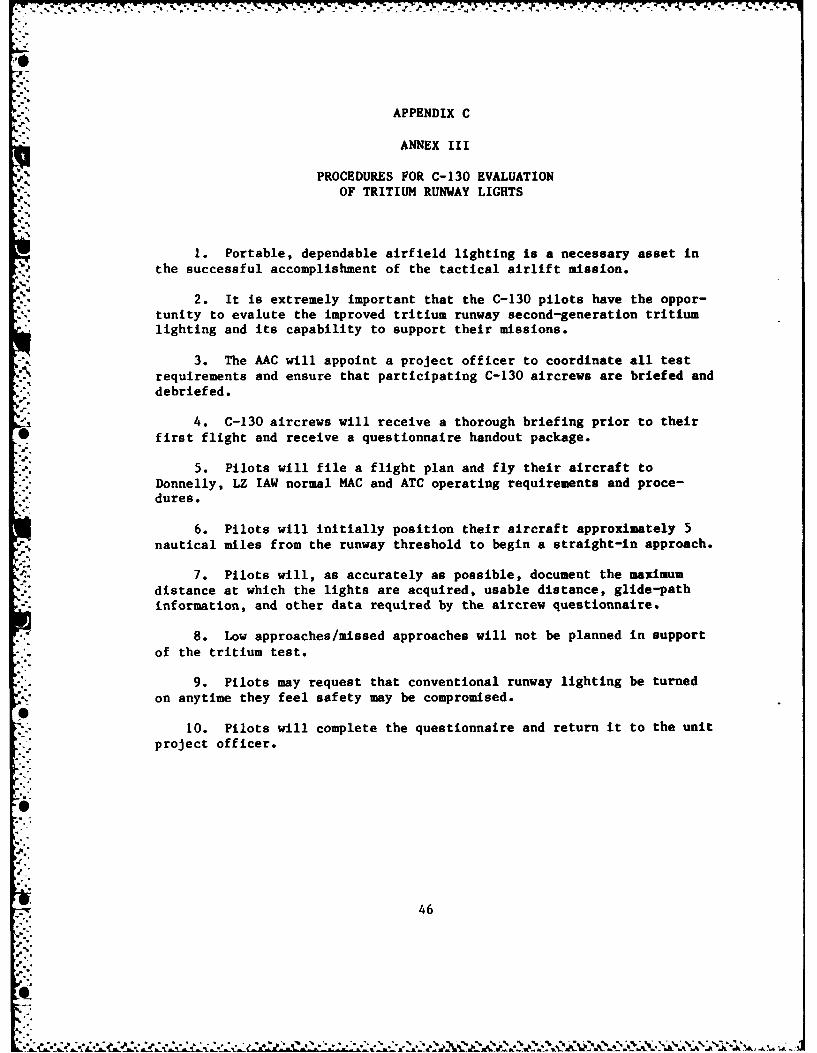
PROCEDURES FOR C-130 EVALUATION
OF TRITIUM RUNWAY LIGHTS
1. Portable, dependable airfield lighting is a necessary asset in
the successful accomplishment of the tactical airlift mission.
2. It is extremely important that the C-130 pilots have the oppor-tunity to evalute the improved tritium runway second-generation tritiumlighting and its capability to support their missions.
3. The AAC will appoint a project officer to coordinate all test
requirements and ensure that participating C-130 aircrews are briefed and
debriefed.
4. C-130 aircrews will receive a thorough briefing prior to their*first flight and receive a questionnaire handout package.
5. Pilots will file a flight plan and fly their aircraft toDonnelly, LZ lAW normal MAC and ATC operating requirements and proce-dures.
6. Pilots will initially position their aircraft approximately 5
nautical miles from the runway threshold to begin a straight-in approach.
7. Pilots will, as accurately as possible, document the maximum
distance at which the lights are acquired, usable distance, glide-path
information, and other data required by the aircrew questionnaire.
8. Low approaches/missed approaches will not be planned in support
of the tritium test.
9. Pilots may request that conventional runway lighting be turned
on anytime they feel safety may be compromised.
10. Pilots will complete the questionnaire and return it to the unitproject officer.
64
76 4
-.- *)*:-iI A ~ ~ ' ~ * -
tl
APPENDIX C
ANNEX IV
TRITIUM RUNWAY LIGHTING- AIRCREW QUESTIONNAIRE
,4
i --
K..
K 47'
,* . . . . . . . . * ,'

APPENDIX C
ANNEX IV
TRITIUM RUNWAY LIGHTING - AIRCREW QUESTIONNAIRE
Instructions: This questionnaire should be completed as soon as possibleafter reviewing the test lights. Please identify acquisition distancefor each approach made. Return to your project officer or return toHQ AAC/DOOS, Elmendorf AFB, Alaska 99506. When evaluating the RL system(RLS), use "outstanding" as if you were evaluating an excellent incan-descent system. A satisfactory system would be your opinion on anacceptable airfield lighting system.
I. General
A. Approach Flown: VOR NDB TACAN Visual
B. Maneuvers: Low Approaches Landings
C. Have you flown approaches and/or landed at this airfieldbefore? Yes No
II. Weather Conditions
A. Cloud Cover: Scattered Broken Overcast
B. Ceiling/Visibility: Height AGL; Distance nm
C. Precipitation: Snow Fog Haze None
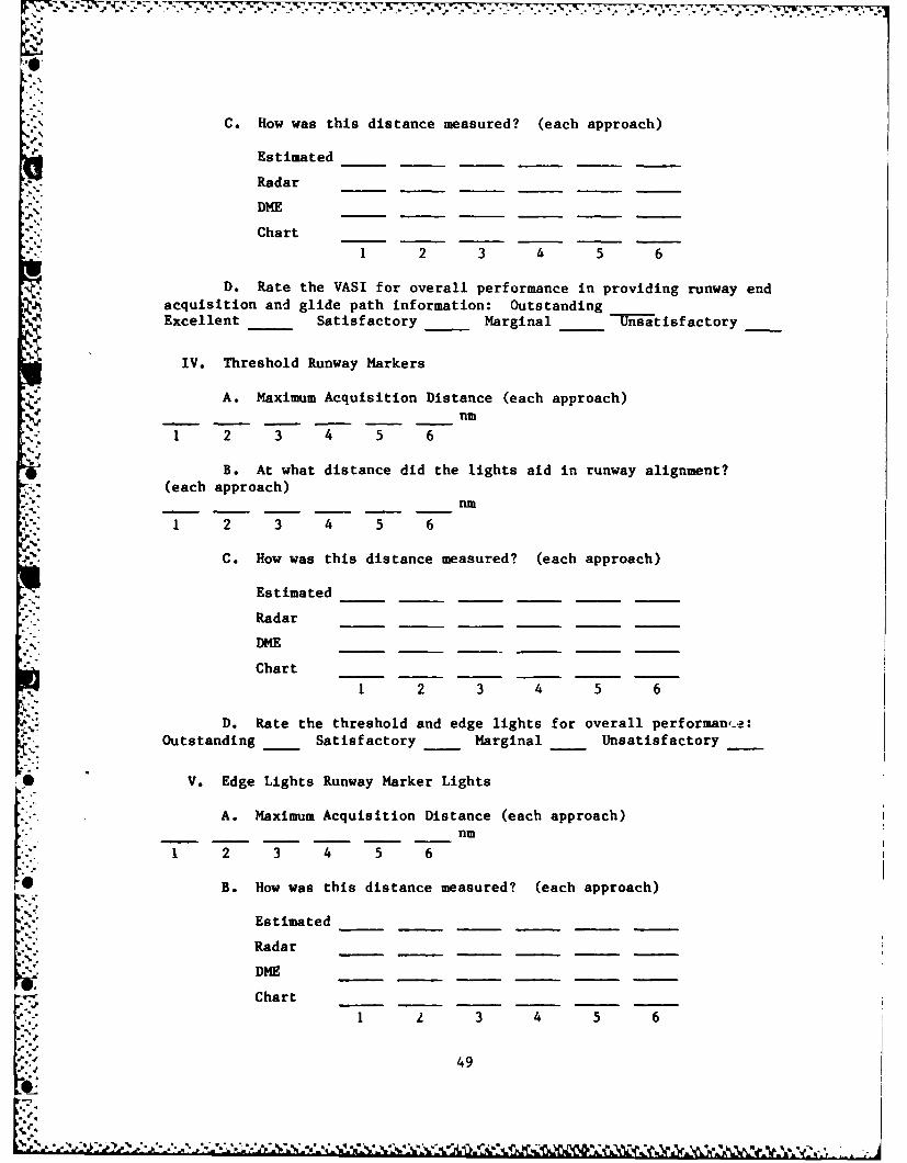
III. VASI Landing System
A. Maximum Acquisition Distance (each approach)
-- - -- -nm1 2 3 4 5 6
B. At what distance did the VASI provide usable "glide path"
information? (each approach) nm
1 2 3 4 5 6
48
C. How was this distance measured? (each approach)
Estimated
Radar
DME__ _ __ _ __ _ __ _
Chart
1 2 3 4 5 6
D. Rate the VASI for overall performance in providing runway endacquisition and glide path information: OutstandingExcellent _ Satisfactory Marginal -Unsatisfactory
IV. Threshold Runway Markers
A. Maximum Acquisition Distance (each approach)nm
1 2 3 4 5 6
B. At what distance did the lights aid in runway alignment?(each approach)
nm
1 2 3 4 5 6
C. How was this distance measured? (each approach)
Estimated
Radar
DME
Chart
1 2 3 4 5 6
D. Rate the threshold and edge lights for overall performan,-e:Outstanding Satisfactory Marginal Unsatisfactory
V. Edge Lights Runway Marker Lights
A. Maximum Acquisition Distance (each approach)nm
1 2 3 4 5 6
B. How was this distance measured? (each approach)
Estimated
Radar
DME_______
Chart
1 2 3 4 5 6
49
4.
! 1 . , . . . . . . .,*~7 - .. *
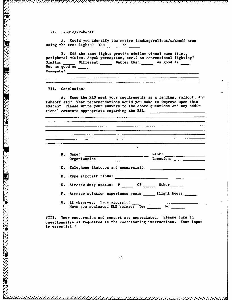
* VI. Landing/Takeoff
A. Could you identify the entire landing/rollout/takeoff areausing the test lights? Yes No___
B. Did the test lights provide similar visual cues (i.e.,peripheral vision, depth perception, etc.) as conventional lighting?
-~~ ~. Similar ____Different ____Better than ____As good asNot as good as ___
Comments:________________________________
VII. Conclusion:
A. Does the RLS meet your requirements as a landing, rollout, andtakeoff aid? What recommendations would you make to improve upon thissystem? Please write your answers to the above questions and any addi-tional comments appropriate regarding the RSL. _____________
* B. Name: _________ _____Rank:_________
Organization ______ ______Location: _______
C. Telephone (Autovon and commercial): ____________
D. Type aircraft flown:__________ ___________
E. Aircrew duty status: P _ __CP Other
F. Aircrew aviation experience years flight hours
* ~~~~~G. If observer: Type aircraft: ______________
Have you evaluated RLS before? Yes ____No ___
VIII. Your cooperation and support are appreciated. Please turn inquestionnaire as requested in the coordinating instructions. Your inputis essential!!
50
~~~~' 'J'** ** * % * * . ** *-' '4

16
APPENDIX C
ANNEX V
INSTALLATION BRIEFING PLAN
51
:.-...
0V
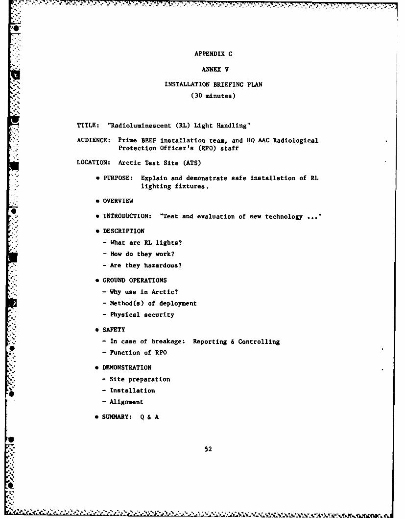
APPENDIX C
ANNEX V
INSTALLATION BRIEFING PLAN
(30 minutes)
TITLE: "Radioluminescent (RL) Light Handling"AUDIENCE: Prime BEEF installation team, and HQ AAC Radiological
Protection Officer's (RPO) staff
LOCATION: Arctic Test Site (ATS)
•9 PURPOSE: Explain and demonstrate safe installation of RLlighting fixtures.
* OVERVIEW
• INTRODUCTION: "Test and evaluation of new technology .. "
e DESCRIPTION
- What are RL lights?
- How do they work?
- Are they hazardous?
* GROUND OPERATIONS
- Why use in Arctic?
- Method(s) of deployment
- Physical security
" SAFETY
- In case of breakage: Reporting & Controlling
- Function of RPO
• DEMONSTRATION
- Site preparation
- Installation
- Alignment
* SUMMARY: Q& A
*52
-cS
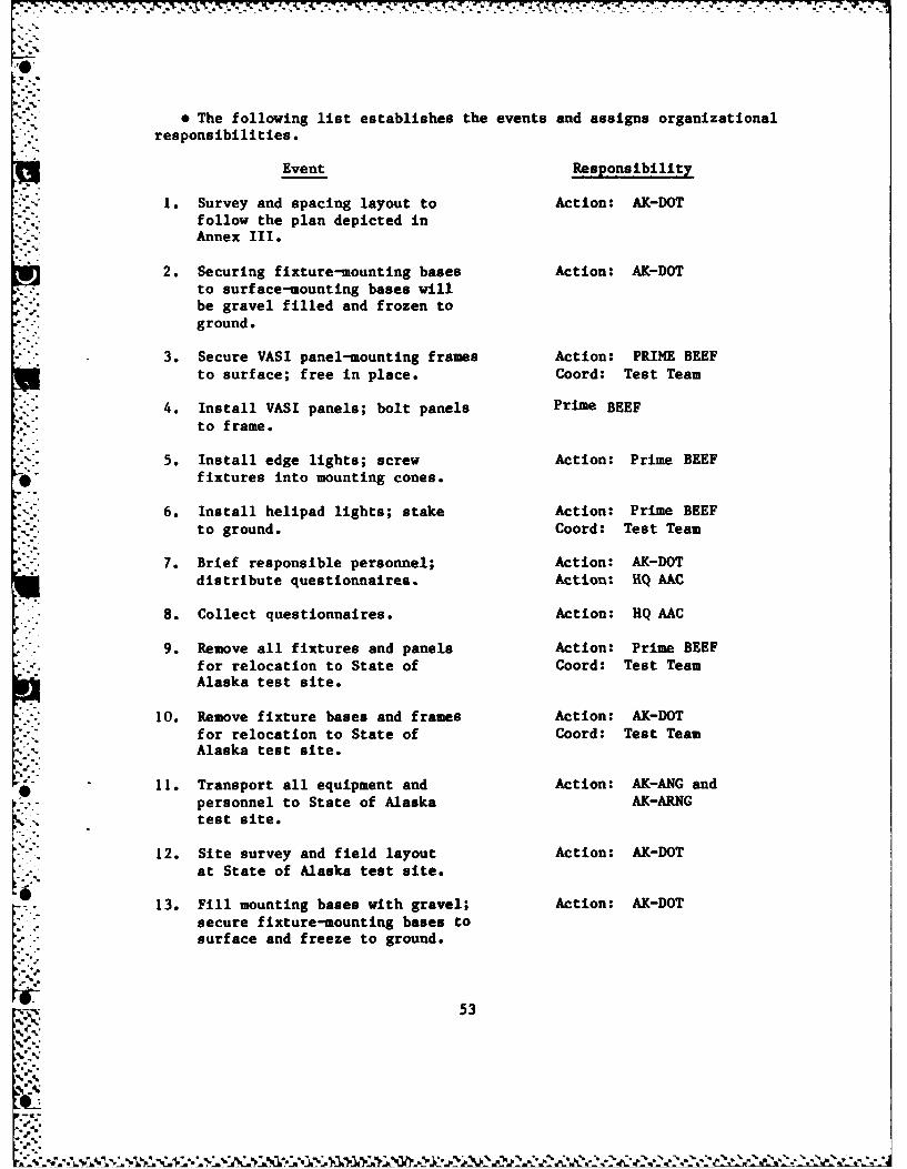
' The following list establishes the events and assigns organizationalresponsibilities.
Event Responsibility
1. Survey and spacing layout to Action: AK-DOTfollow the plan depicted inAnnex III.
2. Securing fixture-mounting bases Action: AK-DOTto surface-mounting bases willbe gravel filled and frozen toground.
3. Secure VASI panel-mounting frames Action: PRIME BEEF
to surface; free in place. Coord: Test Team
4. Install VASI panels; bolt panels Prime BEEFto frame.
5. Install edge lights; screw Action: Prime BEEF*- fixtures into mounting cones.
6. Install helipad lights; stake Action: Prime BEEF. to ground. Coord: Test Team
7. Brief responsible personnel; Action: AK-DOT
distribute questionnaires. Action: UQ MC
. 8. Collect questionnaires. Action: HQ AAC
9. Remove all fixtures and panels Action: Prime BEEFfor relocation to State of Coord: Test TeamAlaska test site.
10. Remove fixture bases and frames Action: AK-DOTfor relocation to State of Coord: Test TeamAlaska test site.
11. Transport all equipment and Action: AK-ANG andpersonnel to State of Alaska AK-ARNGtest site.
12. Site survey and field layout Action: AK-DOTat State of Alaska test site.
13. Fill mounting bases with gravel; Action: AK-DOTsecure fixture-mounting bases tosurface and freeze to ground.
N 53
J "
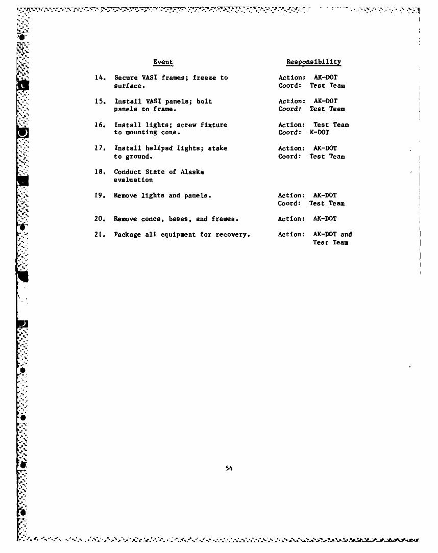
surface. Coord: Test Team
15. Install VASI panels; bolt Action: AK-DOTpanels to frame. Coord: Test Team
16. Install lights; screw fixture Action: Test Teamto mounting cone. Coord: K-DOT
17. Install helipad lights; stake Action: AK-DOTto ground. Coord: Test Team
18. Conduct State of Alaskaevaluation
19. Remove lights and panels. Action: AK-DOT
Coord: Test Team
20. Remove cones, bases, and frames. Action: AK-DOT
-21. Package all equipment for recovery. Action: AK-DOT andTest Team
'.54
S "
Sm
.vntspn.bIt
14. ecue VAI fame; frezeto ctio: A-54
su4c. or:TetTa
,.,"1. Is llVS paes botAto A-T
APPENDIX C
ANNEX VI
TRITIUM RUNWAY LIGHTING - GROUND SUPPORTCREW QUESTIONNAIRE
55
APPENDIX C
ANNEX VI
TRITIUM RUNWAY LIGHTING - GROUND SUPPORTCREW QUESTIONNAIRE
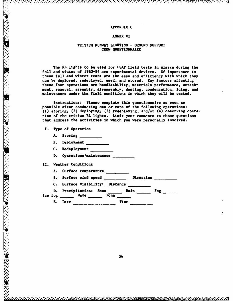
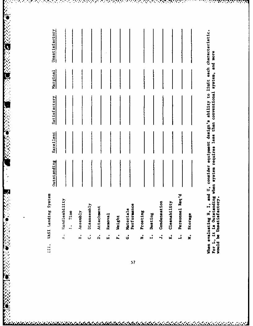
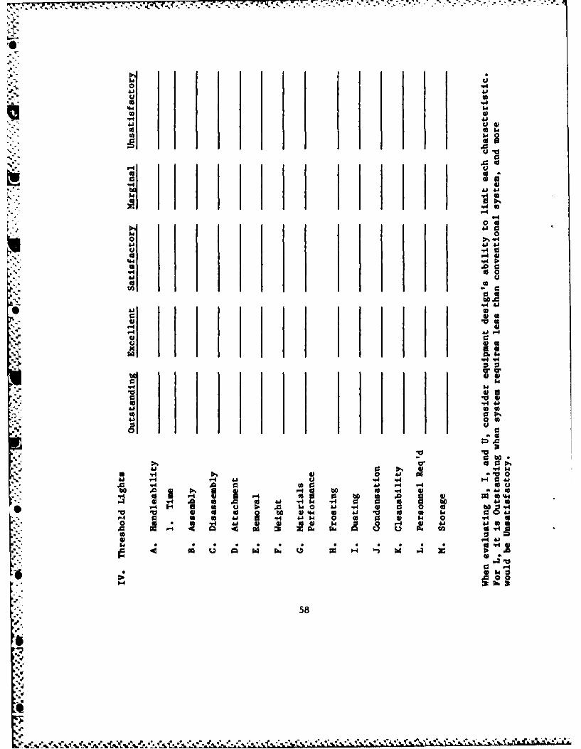
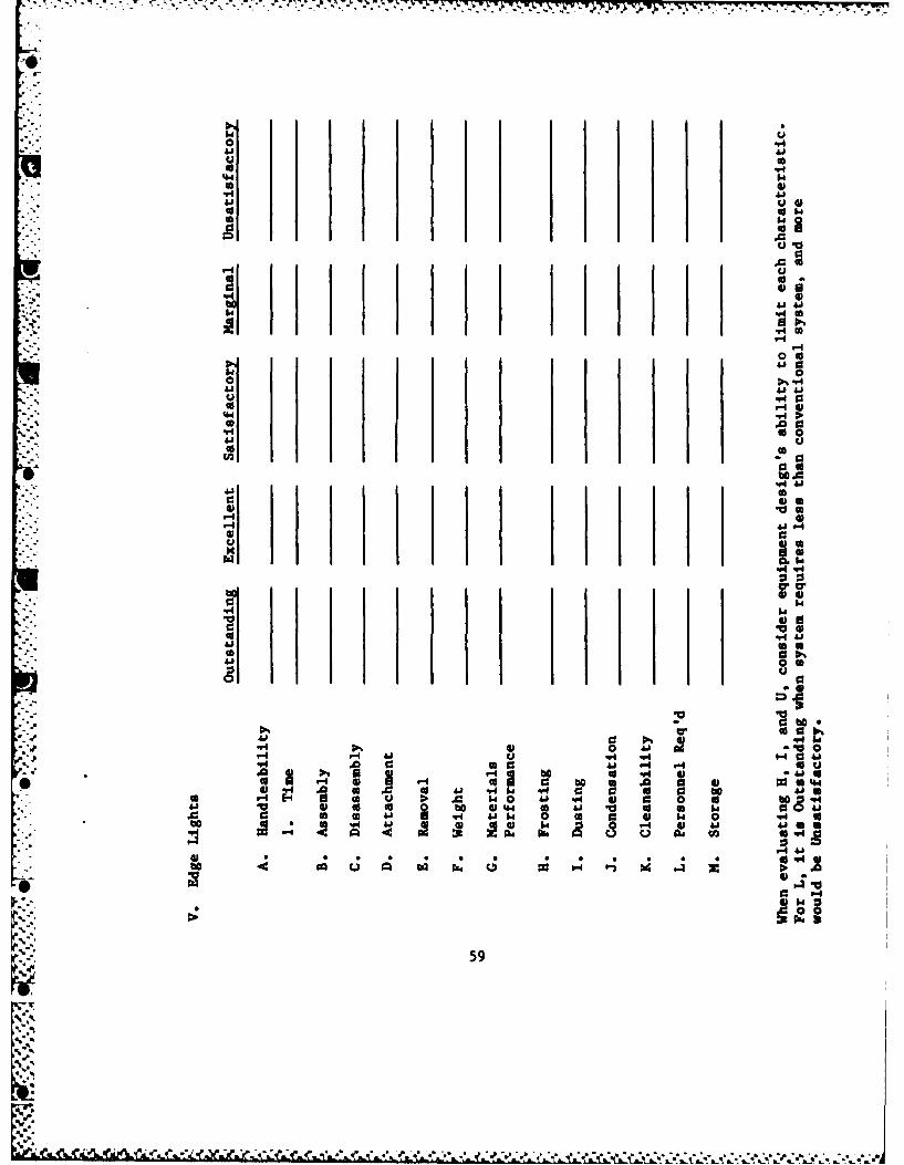
The RL lights to be used for USAF field tests in Alaska during thefall and winter of 1983-84 are experimental devices. Of importance tothese fall and winter tests are the ease and efficiency with which theycan be deployed, redeployed, used, and stored. Key factors affectingthese four operations are handleability, materials performance, attach-ment, removal, assembly, disassembly, dusting, condensation, icing, andmaintenance under the field conditions in which they will be tested.
Instructions: Please complete this questionnaire as soon aspossible after conducting one or more of the following operations:
.. (1) storing, (2) deploying, (3) redeploying, and/or (4) observing opera-tion of the tritium RL lights. Limit your comments to those questionsthat address the activities in which you were personally involved.
I. Type of Operation
A. Storing
B. Deployment
C. Redeployment
D. Operations/maintenance
- II. Weather Conditions
A. Surface temperature
B. Surface wind speed Direction
C. Surface Visibility: Distance
D. Precipitation: Snow Rein Fog
Ice fog Haze None-"--
E. Date Time
56
I %[ *-.
oV4.
0 co
41
00
S.'1 -H
041 0
b 0
46
V4 -4
-4418
U0 9
41 000 -46P0 0
f'p 48
o 06 b'.. be
40 04 0
0
57.
41i04
0 to00
0 "4
4.o.
te 0 4)a 6.4
00aV.5
03
a b4.
4v.0 .0
r- 4 V 4 . 4
.. So 0
00
000w
580
-7 71 - --. -lt -
o~ 14
.41
4it I.1
v!*0
0
0 a
v45* 4
q-4-41104
tv 41
w5w
"61 )541 4.
0 659
VI. Conclusions and Recomendations
A. Give your overall evaluation of the ease of storage/deployment!redeployment/use of tritium RL lights.
* B. List any suggestions you may have for improving the design anduse of the RL lights (handling, storage, etc.).
VII. Responder
Name ______________ __Rank/Rating________
Organization ______________Location_________
Telephone Number_____ _______
60
APPENDIX D
SUMMARY OF ACQUISITION DISTANCES
" .4
',S
%-
.i -
- 'SS4/

.57.
'.4
410 0
.r o 0 U a U 04 4W4 41 0 0 .0 "41.4 A. 61' bo c a bo u 0 v
.0 0 bo 00 0 5.4 0 V4 VFA 00 P4P40 4 4 0 14 0I
41v 4 14 a 4 m 41*41c!0 1W *bo 06 a . v U uU
9- 01 93 0 %4 0 H. 0i &.j- 4.8 000.4 0 CA 1404*1144
0 d 04 04* U 04 w0 - 0 41 goWu* 4 4 01 14 v tc 40 *** 0 a1 *0 0 41
0o 0**. 41 U U 0 A 0 4 400 1,14 o"4 41 1 04*0 5 40 0 .4 1 41 0 4*4*
U4 U3 I4 . 61. 0"4&bO U 3 00 0 m41 0 41* - "40 93 9-
4 "4 "44 0 r4 0 -I0 v4 O v4 0 - 5.d44 r-4 64 to 4*.4 0. Vq " 4
4 X 0 000 64"4P-1 0. 0.0cn00 0bO bo ho u~ 0l9 0 V-4 93 C4 ot (' -4 &j U 0
A414 4 WO1U
pa
U
E-4 41-4 01
0. 5.4 N44" " C4 " " 4 "4 "4 "4 "4 "4 "4
-1 w. N* N * C4 N (4 4 4.4 4
% H
) . . . . C4 0. C4 C4 C. p.4 C4 N p.
00 i i 0 in 0 00 0 0 00 0
0 LI * M en 0 * 0 *) . 0 0 * 0 04 14 N4 C4 N o-I N4 V; 14 W* IA N 4 A N4
IS
OCI iin0in 0 in 00C0 0 0 00 0{4 N SV 4 VS 0-4 NC VS WS 4 1; C44 S
in InOiA a 0 0 00 00i
'1 ~ e 0 * *M*
C4 AS~ VS VS H- 4 CAI I 4 C4 4 A
C A IA IA 0n 00 IAG 4C
0 .62.5 .
S.V .1. - - --%
00
000 6.. 41 6.4 4.80
4.804 4D 0 9 4.1 0c 10U(A 4.1 A 0 H 441 14 "4
00 . 4.. 4). %4 0 4.co. 06 0 4144A8 0 0 S
S48 0 448 93 0. 0 4. 4
90a 0 "4 .0o 0 .,. 4o.0 41 u 41 o4 0 10*d 00 to 4.o 9 8 ~ r .0 ) A
4.4 0 4.8 M 0V4 4 4)893 4) .0 0 to V441 000 $4FA 0 0 w 00 -A A0
0 CO C 4054.8. I "48 0 0 00 4.U4A t to. 04. 0 -v4 ." 4 0 4J. co 0j
q 0.0 O O S r-4 r-0o0 m - A 4 I 48"4 co 9 41 4 4.8 to c 4 u" .0
4 934 4.84.8 04 u 0 .0 4- 440 0 r. 4co 000 ccc o U3 J 4 0 b * 004.8 r 1 4.80
vI6 54 X4 IV 08 4 4 c 04 ".4 6.04j0C 0 4J tv-- bO b0M0 .,4 03 U1 US to 0 0
v-4V "4.4 So t4. 4.0 . 0.
v.4 v-40 ~ '4 .0 5-4. 4 0 00'U 0 OC) 4.44)O ~ oU 0. 41
0 -.4 0 00 0
0 4.4 0q 0 4 0 0 0 00 0 0
4.I 04I v4 0 4 C4C
CIC
0 44 00 0 -0 0 00 0 0
H 00 ~ -0 04 0v cv. (. V
0 0
00 0 00 0 0
Go NN 0 C1 Nn N k
000 00 0 4 04 0 04 0 0
6:. . . . * .-C8 N c r% - ~% ~63 ~
0% 1 0
8-o4
0 0 0 @"14 a041 44 .41 "4 u .0
.4044 **84 ca *1 to.u 00 wS k 0 0) 9 .0
C0 0.. C3 H &4 0 ObO .f boO
cy ..HI 4.8 44V1 9 o
00 q4 "f0 44 4 S 4. O. 0 V 48 4A : s A 0 o%.0O .05 418. %0 ~ ~ ~ ' 44. P%~ A a u-I A ".0 410 0 50.jVIdO
48 08 0 0% 41$ &1 bo C3 "4U IN P4 048 0 Ui400 j ~ 0 w 0 .0u- 0 aJ x Aw4 Aib40 i " - OI 4J~ 48 0 0 - 4 ~0 10 4 48.'
od 41 4 0 (aE A.r a44 J U J 0% 0 w4 S % UW 4P0 A 48
0 to 48 Ic4. - OiA J4 4 0 0 4 8-A 0 9 $4 0aJ -A .00. 484. 44u 041 44 ( a a 4 t
sP-4
'-4 - -- 4
40 0) 0 0 0
13 -4V-
410 44 0 0 0 0H c col CV) CV)(W 0 0 0) 0 0
E- U
4 0 ne
0 0 40 0 00 ao Un U
U~~L CV) MS VS V 8 oh I
VS - S~0 C4 -4 AS 1
00 Ch a-4 0n 0M V
14 u 4 c" en en cn c 0 n N n m
-64
-- -- l-
r1 4' 0 0 4. 4 0 A40w 10 0b " 04 $44 ." - 1 6
0- " .4 0 01 Q -4U1 41. U2O to.- 41 1- 4
) W t 0 to0 -A u4. 0 *A0 to 0, 40 b,S4 0 4 93 -A44.1 0 -- 4 bC wf 44 S -A 4. 0
(a ~ ~ 04 41*0 o b 0 " ~ %4 4.1 U A0 o0 4
414 IUl 1-4 CC 0 q. 4J4 r toU bCir to1 0'* 44 to "1.4(44 afir- W U 0 bU 0. WU V4 .0 O 0 4.Q5004V4 4 0 0 41 @6a 6j 00-0 " r& 14004.W5'
0 4 0 0. C 4 44.1 A -044.50 014. O1- 0 A ) -4 "4 "4 U-V 0. V4 934454 4 US4 14 4
00 0 0 0
0 0.
E-4 - O %O %O 0 -4 -4 - -4 - -
0 0 0 In0 0 C 0 0 0'C'4 - 1 4 (; 14 0; 04 (A N 4 C4
cA en ~ (A 00 ' a0 0 0 (A in tn
wA C4 4 A A (. N (A -. 4 4
w U 0 0 Q * l 0 * In S n * 1. in
0wen 0 0 0 0 mA ( 0 CI in i
(A 004 000 04 04 (A 14 04 A B 4
v in 0 00 0 00 0 in 0 0 GO 00
c4 0 0 N en 0 0 0 -w
N N4 -4 N 4 A - 4 N 4 N -
0' 0- 4 (n 4 n %D ' % GO 0' 0
65
A~
bO
44
1 -1 4 1
to ) o0 41'
V4 g: 0...40 bo
( o 41 0
00 0
44 0
011
z 41
0 00"i co 0 0"440$4 -4
"4 "4
00
0 4.0
I-V 00 -.
1-410-4C.,4 r L
cni001n i
[0 or66
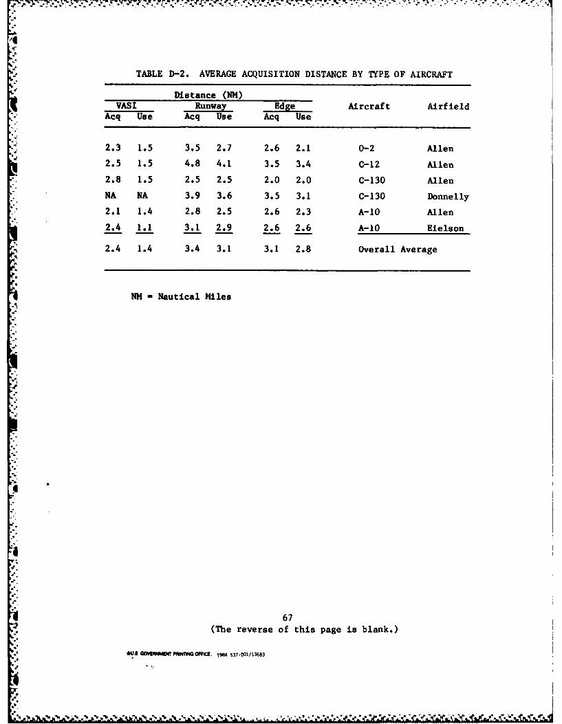
TABLE D-2. AVERAGE ACQUISITION DISTANCE BY TYPE OF AIRCRAFT
Distance (NM)VASI Runway Edge Aircraft Airfield
Acq Use Acq Use Acq Use
2.3 1.5 3.5 2.7 2.6 2.1 0-2 Allen
2.5 1.5 4.8 4.1 3.5 3.4 C-12 Allen
2.8 1.5 2.5 2.5 2.0 2.0 C-130 Allen
NA NA 3.9 3.6 3.5 3.1 C-130 Donnelly
2.1 1.4 2.8 2.5 2.6 2.3 A-10 Allen
2.4 1.1 3.1 2.9 2.6 2.6 A-10 Eielson
-I 2.4 1.4 3.4 3.1 3.1 2.8 Overall Average
NM - Nautical Miles
".o
67(The reverse of this page is blank.)
*' /*4.. W NWIMWTIN'I O FFC[: 1984 531-001/13683
% . Pr

771.., u.i-.
FILMED
1-85
DTlC