OSI Network Layer - Prince Sultan University, Riyadh ...info.psu.edu.sa/cs/menezi/files/Chapter...
78
OSI Network Layer Network Fundamentals Network Fundamentals Chapter 5
Transcript of OSI Network Layer - Prince Sultan University, Riyadh ...info.psu.edu.sa/cs/menezi/files/Chapter...

OSI Network Layer
Network FundamentalsNetwork Fundamentals
Chapter 5

Objectives
� Identify the role of the Network Layer, as it
describes communication from one end
device to another end device.
� Examine the most common Network Layer � Examine the most common Network Layer
protocol, Internet Protocol (IP), and its
features for providing connectionless and
best-effort service.
� Understand the principles used to guide the
division or grouping of devices into networks.

Objectives
� Understand the hierarchical addressing of
devices and how this allows communication
between networks.
� Understand the fundamentals of routes, next � Understand the fundamentals of routes, next
hop addresses and packet forwarding to a
destination network.

Outline
� IPv4
� Network layer: Communication from host to host
� IPv4: Example of network layer protocol
� IPv4 packet header� IPv4 packet header
� Networks: Dividing hosts into groups
� Creating common groups
� Why separate hosts into networks
� Dividing networks from networks

Outline
� Routing: How data packets are handled
� Gateway: The way out of the network
� Route: A path to a network
� Routing table entries
� Packet forwarding: Moving the packet toward its
destination
� Routing processes: How routes are learned
� Static routing
� Dynamic routing
� Routing protocols

IPv4
� The Network layer, or OSI layer 3, provides services to exchange the individual pieces of data over the network between identified end devices.
� To accomplished this end to end transport the segment will go through layer 3 processes:� To address the packet to the proper destination.
� Encapsulate the packet with necessary data for delivery.
� Route the packet through the web of connected network for delivery.
� The destination host decapsulate the data for processing.
� The protocol used in the Internet’s network layer is the called the Internet Protocol (IP).

Network layer: Communication from host to host

Network layer: Communication from host to host
� The network layer receives segments of data (PDU) from the transport layer.� Contains application data + transport header (either TCP or
UDP).
� The network layer adds a header to the segment � The network layer adds a header to the segment received:� Contains information to perform network-layer functions
such as addressing.
� The format of the header is defined by a network layer protocol such as IP.
� Four basic processes of network layer: addressing, encapsulation, routing, decapsulation.

Addressing
� IP requires that each sending and receiving
device / host to have a unique IP address.
� For a successful data transfer, both the
source and destination IP addresses need to source and destination IP addresses need to
be specified.
� Destination IP address enables the packet to be sent to the correct receiving host.
� Source IP address enables the receiver to send a reply to the sending host.

Encapsulation
� Encapsulation refers to the process of adding
an IP header to the segment received from
the transport layer.
� IP header + transport-layer PDU = network-layer � IP header + transport-layer PDU = network-layer PDU.
� Network-layer PDU is also called a packet.
� Among others, the IP header contains:
� Source IP address
� Destination IP address

Encapsulation

Routing
� Routing refers to the process that a router performs when receiving a packet.
� This process involves:� Analyzing destination address information.� Analyzing destination address information.
� Using the address information to select a path for the packet.
� Forwarding the packet to the next router.
� The packet header contains all the information required for the packet to travel through the network to the destination host.

Routing
� The path that the router chooses depend on the router configuration and information about the destination network.� Done by referring to the router’s routing table.Done by referring to the router’s routing table.
� A packet may need to travel several hops before it reaches the receiving host.� A hop refers to the travel from one router to
another router.
� The last router will then forward the packet to the destination host.

Decapsulation
� When the receiving host receives the packet, it examines the destination address to verify that the packet was addressed to this device.
� If the address is correct, the packet is � If the address is correct, the packet is decapsulated.� Decapsulation refers to the process of taking off
the IP header from the packet.
� The remaining segment (layer 4 PDU) is then passed to the appropriate service at the transport layer

Network Layer Protocols
Protocol Description
Internet Protocol version 4 (IPv4)
Most widely used network protocol. Basic protocol of the Internet
Internet Protocol version 6 (IPv6)
Currently in use in some areas. Will work with IPv4 and likely to replace itversion 6 (IPv6) IPv4 and likely to replace it
Novell IPX Part of Novell NetWare, a widely popular internetworking protocol in the 1980s and 1990s
AppleTalk Apple Computer’s proprietary networking protocol
Connectionless Network Services (CLNS)
A protocol used in telecommunication networks that does not require established circuits

IPv4: Example of Network Layer Protocol
� The network-layer protocol used in the Internet is the Internet Protocol (IP).
� The version of IP widely used in the Internet currently is IPv4.currently is IPv4.
� The next version of IP, which is IPv6 has already been developed and currently being used in certain areas.� IPv6 can operate alongside IPv4.
� In the future, IPv6 is expected to replace IPv4 throughout the Internet.

IPv4: Example of Network Layer Protocol
� IP was designed as a protocol with low
overhead.
� Provides only the functions that are necessary to deliver a packet from a source to a destination deliver a packet from a source to a destination over an interconnected system of networks.
� IP was not designed to track and manage the
flow of packets.
� These functions are performed by other protocols in other layers.

IPv4: Example of Network Layer Protocol
� IPv4 characteristics:� Connectionless
� No connection is established before sending data packet.
Best effort (unreliable)� Best effort (unreliable)� Does not guarantee data delivery.
� This reduces the overhead at routers in terms of processing time and bandwidth usage.
� Media independent� Operates independently of the medium carrying the
data.

IPv4: Example of Network Layer Protocol

Connectionless
� IP is connectionless:
� No need to exchange control information to establish end-
to-end connection before data transfer.
� Does not require any field in the header to maintain
connection.connection.
� This reduces the overhead of IP.
� Connectionless packet delivery may result in packets arriving at the destination out of sequence.
� If out-of-order or missing packets create problems for the
application using the data, then upper layer services will
have to resolve these issues.

Connectionless

Connectionless

Best Effort
� The IP protocol does not burden the IP service with providing reliability. It is an unreliable protocol.� Unreliable means that IP does not have the capability to
manage, and recover from, undelivered or corrupt packets.
� Compared to a reliable protocol, the IP header is � Compared to a reliable protocol, the IP header is smaller. � Transporting these smaller headers requires less
overhead.
� Less overhead means less delay in delivery.
� Reliability will be managed by an upper layer protocol (such as TCP).

Best Effort

Media Independent

Media Independent
� It does not matter whether IP packets are carried over what type of media.
� The only difference between the different media is just how
the bits are represented by the signals.
The only issue that the network layer needs to � The only issue that the network layer needs to consider is the maximum size of PDU that each medium can transport.
� Different medium / link layer technology has its own
maximum packet size.
� This maximum size is called the maximum transfer unit
(MTU).

Media Independent
� The network layer must prepare the packets such that their size do not exceed the MTU.
� However, since a packet may go through different media along the path, it is still different media along the path, it is still possible for a packet to be forwarded to a media with a smaller MTU than the packet size.� In this case, the router needs to fragment the
packet into smaller packets.
� This process is called fragmentation.

IPv4 Packet Header

IPv4 Packet Header
� Version� Indicates IP version, either 4 or 6.
� Internet Header Length (IHL)� Specifies the size of the packet header.
Packet Length� Packet Length� Specifies the entire packet size (in bytes), including header
and data.
� Identification, Flag and Fragmentation Offset� Used for fragmentation.
� Enables fragmented IP packets to be reconstructed correctly by the receiving host.

IPv4 Packet Header
� Time to Live (TTL)
� An 8 bit field that specifies the maximum hops the packet
can take before it is considered lost or undeliverable.
� The value is decreased by one each time the packet is
processed by a router (that is, each hop). processed by a router (that is, each hop).
� When the value becomes zero, the router discards or
drops the packet and it is removed from the network.
� Prevents a packet from circulating forever in the network.
� Protocol
� An 8-bit value that specifies the upper layer protocol that
will receive this packet after decapsulation.

IPv4 Packet Header
� Header Checksum� Used for storing error checking code.
� Source Address� IP address of the sending host.
� Destination Address� Destination Address� IP address of the receiving host.
� Options� Additional fields to provide extra services.
� Rarely used.
� Padding� Used to fill in bits when header data does not end on a 32-
bit boundary.

Networks: Dividing Hosts into Groups
� Historically, IP-based network was managed as one large network.� As the network grew, so did the issues related to
its growth.
� To alleviate these issues, the large network is separated into smaller that were interconnected.
� These smaller networks are called subnetworks or subnets.
� Dividing a network into subnets makes it easier to be managed.

Creating Common Groups
� Hosts can be grouped:� Geographically
� Example: Grouping by office locations.
� Based on a specific purposeBased on a specific purpose� Example: Artists need high bandwidth to create video,
but salesperson need 100% reliability and speed.
� Allows network resources to be allocated accordingly.
� Based on ownership� Example: Certain network can only be accessed by a
certain group of people.
� Provides a boundary for security enforcement

Creating Common Groups

Creating Common Groups

Creating Common Groups

Why Separate Hosts into Networks?
� As network gets larger, the following issues
will arise:
� Performance degradation
� Security issues� Security issues
� Address management
� Dividing a big network into smaller subnets
can solve or reduce the issues above.

Performance Degradation
� Dividing a large network into smaller ones can reduce the broadcast domain.� A broadcast is a message sent from one host to all other
hosts in the network.
� Useful for certain applications such as DHCP.� Useful for certain applications such as DHCP.
� A broadcast is sent to all hosts in the same network.
� By having small networks, a broadcast sent by a host will only be sent to the other hosts in the sending host’s network.
� Managing the size of broadcast domain ensures that network and host performances are not degraded to unacceptable levels.

Performance Degradation

Security Issues
� Not all hosts in the network should be accessible by everybody.
� It is important for the network to provide a way to restrict user access.� To ensure that data cannot be accessed by unauthorized
users.To ensure that data cannot be accessed by unauthorized users.
� Security between networks is implemented using an intermediary device (a router or firewall) at the perimeter of the network.� Firewall is configured to permit only known, trusted user to
access the network.
� Enable all access to network resources to be prohibited, allowed or monitored.

Security Issues

Address Management
� A host needs to know the address of the receiving host in order to send data.
� For a large network with many hosts, this can cause quite a lot of overhead (e.g. memory).� Since a host needs to store the addresses of all the other
hosts.Since a host needs to store the addresses of all the other hosts.
� This can be solved by grouping hosts together.� A host only needs to store addresses of other hosts in the
same group.
� For other destinations, the hosts only need to know the address of the gateway router.� A gateway is just a router that serves as an exit from a
network.

Address Management

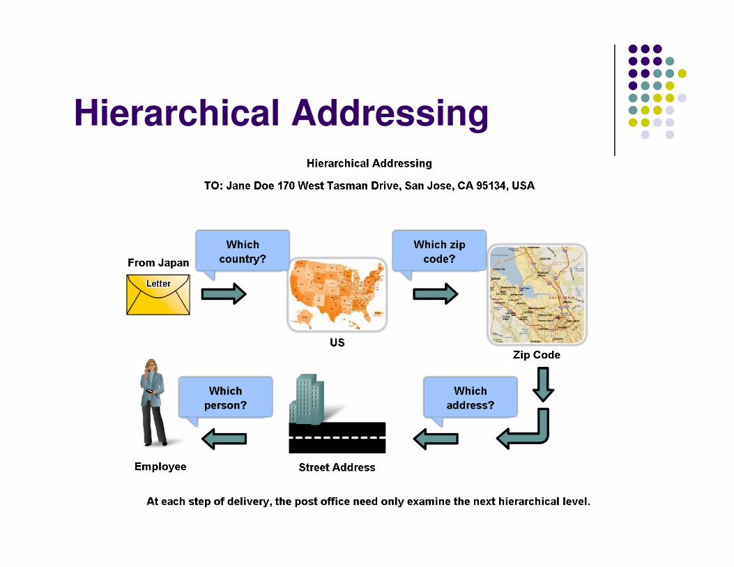
Hierarchical Addressing
� Sending data from one network to another
can be a difficult task.
� Need to know where the destination network is.
� To support data communication between � To support data communication between
networks over an internetwork, network layer
addressing is designed to be hierarchical.
� The concept is similar to the addressing
scheme used in writing an address for the
postal service.
Hierarchical Addressing

Dividing Networks from Networks
� The 32-bit IPv4 address is hierarchical and is made up of two parts:� Network portion – identifies the network.
� Host portion – identifies the host on that network.
� For convenience, IPv4 addresses are divided in four groups of eight bits (octets).
� For convenience, IPv4 addresses are divided in four groups of eight bits (octets).� An octet is a binary number of eight digits, which equals
the decimal numbers from 0 to 255.
� Each octet is converted to its decimal value and the complete address written as the four decimal values separated by a dot (period).� Example: 192.168.18.57
� This format is called “dotted-decimal notation”.

Dividing Networks from Networks

Dividing Networks from Networks
� All hosts on a given network share the same network portion, but each of them must have a unique host portion.

Dividing Networks from Networks
� The network portion of an IP address is inherited down through a network hierarchy, as illustrated below.

Dividing Networks from Networks
� The number of bits of an address used as the network portion is called the prefix length.� Example: If a network uses 24 bits to express the network
portion of an address the prefix is said to be /24.
� In the devices in an IPv4 network, a 32-bit number called a � In the devices in an IPv4 network, a 32-bit number called a subnet mask is used to indicate the prefix.
� Routers in the network only need to check the network portion of an IP address to know how to reach the destination network.� No need to know the location of each individual host.
� Makes it easier and faster for a router to do its task.

Dividing Networks from Networks
� A network can further be divided into smaller networks by using a technique called subnetting.
� Done by extending the network portion of the address by
“borrowing” bits from the host portion.
These borrowed bits are then used as network bits to � These borrowed bits are then used as network bits to
represent the different subnetworks within the range of the
original network.
� Subnetting allows the network administrator to divide networks to meet different needs, while at the same time ensuring each host has a unique IP address.

Routing: How Data Packets are Handled
� When a packet leaves a host, where the packet go depends on the location of the destination host.
� Done by examining the network portion of the destination
address.
If the destination host is on the same network, the packet � If the destination host is on the same network, the packet
will be sent to the local network.
� If the destination host is on a different network, the packet
will be delivered to the gateway router.
� The gateway (also called default gateway) is a door between the local network and the outside network.

Routing: How Data Packets are Handled

Routing: How Data Packets are Handled
� In traveling from the source host to the destination host, a packet may cross many networks through many routers.
� At each router, the router must make a forwarding decision.� Decide where to forward the packet next.
� This process is also known as routing.
� The packet is then forwarded to the next-hop router.� The packet forwarding then becomes the responsibility of
the next router.
� The process is repeated until the packet arrives at the destination host.

Gateway: The Way Out of the Network
� The gateway is a router with one of its interfaces connected to the local network.
� This interface will have an IP address that has its network
portion equal to the network portion of the addresses of the
other hosts in the local network.other hosts in the local network.
� The default gateway must be configured in every hosts in the network.
� On a Windows computer, the Internet Protocol (TCP/IP)
Properties tools are used to enter the default gateway
address.

Gateway: The Way Out of the Network

Route: A Path to a Network
� Each host and router must have routes specified for packets to be forwarded.� A route is defined in terms of the next-hop router.
� For a particular destination address, the packet will be forwarded accordingly based on the route specified on the device.device.
� Without a route, the packet cannot be forwarded and may have to be discarded.
� The routes are stored in the device’s routing table.� The routing process will use the destination IP
address to identify the proper route to be used.� Done by referring to the network portion of the destination
IP address.

Route: A Path to a Network

Route: A Path to a Network
� By default, a device knows the route to the network that it is directly connected to.� The network directly attached to the device’s network
interface.
� All other routes, however, must be configured or � All other routes, however, must be configured or acquired via a routing protocol.� These are routes to remote networks.
� Routes in a routing table have three main features:� Destination network
� Next-hop
� Metric

Route: A Path to a Network

Route: A Path to a Network
� When a packet comes in, the router will check whether the destination network is specified in the routing table.� If it is, the packet will be forwarded to the next-hop router
specified by that route.specified by that route.
� If not, the packet will be forwarded to a default route.
� The default route needs to be configured into the router.
� If there exists multiple paths to the same destination, the metric is used by the routing process to decide which route will appear in the routing table.

Route: A Path to a Network
� A host also has its own routing table.
� This table is used to forward packets originating from that
host.
� The host’s routing table is derived automatically from the connected network and the configuration of from the connected network and the configuration of the default gateway.
� The default gateway acts like the local default route.
� The routing table of the host contains:
� Its direct connection or connections to the network.
� Its own default route to the gateway.

Route: A Path to a Network

Routing Table Entries
� The destination network shown in the routing table represents a range of host addresses or a range of network and host addresses.
� The hierarchical nature of IP address allows one entry to represent a large general network and another entry to represent a subnet in that same another entry to represent a subnet in that same network.
� When forwarding a packet, the router will take the most specific route.� A packet may match two entries in the table, one for a
subnet, one for a larger, general network.
� In this case, the route for the subnet will be chosen.

Routing Table Entries
� If a specific subnet is not in the routing table but the larger network that holds the subnet is known, the router will send the packet to the larger network.
� Trusting that another router will find the subnet.
� If none of the entry in the routing table matches the destination address, the default route will be chosen.
� If no default route is configured, the packet has to be dropped.

Routing Table Entries
� Example: Say that a packet arrives with a
destination address of 10.1.1.55. Then the
precedence would be:
� 10.1.1.0� 10.1.1.0
� 10.1.0.0
� 10.0.0.0
� 0.0.0.0
� Dropped

Packet Forwarding: Moving the Packet Toward its Destination
� Routing is done packet-by-packet and hop-by-hop.
� Each packet is treated independently in each router along the path.
� At each hop, the router examines the destination IP � At each hop, the router examines the destination IP address for each packet and then checks the routing table for forwarding information.
� The router will do one of three things to the packet:
� Forward it to the next-hop router
� Forward it to the destination host
� Drop it

Packet Forwarding: Moving the Packet Toward its Destination

Packet Forwarding: Moving the Packet Toward its Destination

Packet Forwarding: Moving the Packet Toward its Destination

Routing Processes: How Routes are Learned
� Routing requires that every hop, or router, along the path to a packet's destination have a route to forward the packet.� Otherwise, the packet is dropped at that hop.
� The routing table contains the information that a router uses in its packet forwarding decisions.The routing table contains the information that a router uses in its packet forwarding decisions.
� For an efficient routing decision, the routing table must represent the most accurate state of network pathways that the router can access.� Out-of-date information may cause the packet to be
forwarded to the next-hop that is not very appropriate.
� This may cause delays or packet loss.

Static Routing
� In static routing, routes to remote networks are manually configured in the router.� Default routes are normally statically configured.
� The decision on routes to be taken must be � The decision on routes to be taken must be made by the network administrator.� The routes are chosen based on the network
administrator’s knowledge about the internetwork structure.
� The administrator will then configure the chosen routes into the router.

Static Routing
� If the internetwork structure changes or if new networks become available, these changes have to be manually updated on the routers involved.
� Static routing has a high administrative cost.
� Network administrator has to actively monitor the network
to see whether the configured routes are still valid and up-
to-date.
� If updating is not done in a timely fashion, the routing information may be incomplete or inaccurate.
� This will result in packet delays and possible packet loss.

Static Routing

Dynamic Routing
� In dynamic routing, routers learn routes automatically from other routers in the same internetwork.� Routers send routing updates to each other.
� Routing messages are sent using a routing protocol.� Routing messages are sent using a routing protocol.
� Dynamic routing has higher processing and bandwidth overhead.� Due to the need send, receive and process routing
messages.
� However, once configured, the routers can manage routes themselves with little intervention from network administrators.

Dynamic Routing

Routing Protocols
� Routing protocol is a set of rules by which routers dynamically share their routing information.
� When a router detects any change in the network, it will update its routing table and pass this information to the other routers.to the other routers.� The change can be in the form of link failures, the
availability of a new network, change in link metric, etc.
� The other routers will receive this update information and in turn will update their routing tables as well.
� The goal is to make sure all routers in the network to have an up-to-date information about the network.

Routing Protocols
� Routing protocols commonly used in the Internet are:� Routing Information Protocol (RIP)
� Open Shortest Path First (OSPF)
� Enhanced Interior Gateway Protocol (EIGRP)� Enhanced Interior Gateway Protocol (EIGRP)
� All routers in the network must be using the same routing protocol.
� Regardless of the routing protocol used, they all do pretty much the same functions:� To distribute updated network information.
� To update the routing table entries of a router.