Orthogonal Drawing Kees Visser. Overview Introduction Orthogonal representation Flow network ...
27
Orthogonal Drawing Kees Visser
Transcript of Orthogonal Drawing Kees Visser. Overview Introduction Orthogonal representation Flow network ...
Orthogonal Drawing
Kees Visser
Overview
Introduction Orthogonal representation Flow network Bend optimal drawing
Introduction
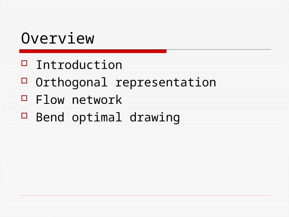
Orthogonal drawing Given embedding Only vertical or horizontal line segments Maximum degree of 4
Introduction
Uses in VLSI circuits Minimize bends Finding an orthogonal drawing of
graph G with the minimum number of bends without a fixed embedding is NP-Complete.
Introduction
Tamassia and Garg and Tamassia found algorithms to find a minimal bend orthogonal drawing of graph G in polynomial time.
Orthogonal Representation
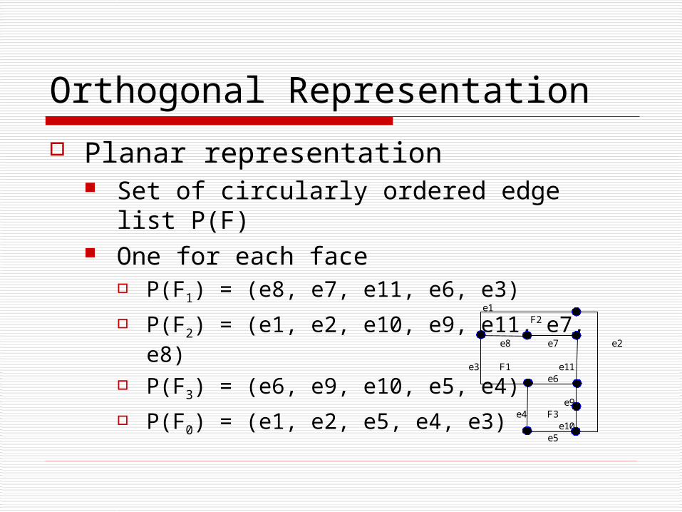
Planar representation Set of circularly ordered edge list P(F) One for each face
P(F1) = (e8, e7, e11, e6, e3) P(F2) = (e1, e2, e10, e9, e11, e7, e8) P(F3) = (e6, e9, e10, e5, e4) P(F0) = (e1, e2, e5, e4, e3)
e1F2
e8 e7 e2
e3 F1 e11e6
e9e4 F3
e10e5

Orthogonal representation
Definitions: An edge appearing in the same list twice
is a bridge An angle formed by to edges is a vertex-
angle An angle formed by two line segments at
a bend is a bend-angle Both vertex angles and bend angles are
90, 180, 270 or 360 degrees
Orthogonal representation
Facts: The sum of vertex-angles around any
vertex is 360 degrees The sum or the angles inside any facial
polygon is (2p-4)90 degree, and the sum of the angles of the outer facial polygon is (2p+4)90 degrees, where p is the number of edges
Orthogonal representation
Orthogonal representation 1 list for each face Each element in the list has 3 values, the
edge number (Er), a bit string and the angle formed in the face from this edge to the next edge (Ar).
The bit string indicated the bends in the line. A 0 indicates a 90 degree bend, 1 means 270 and ε means a straight line
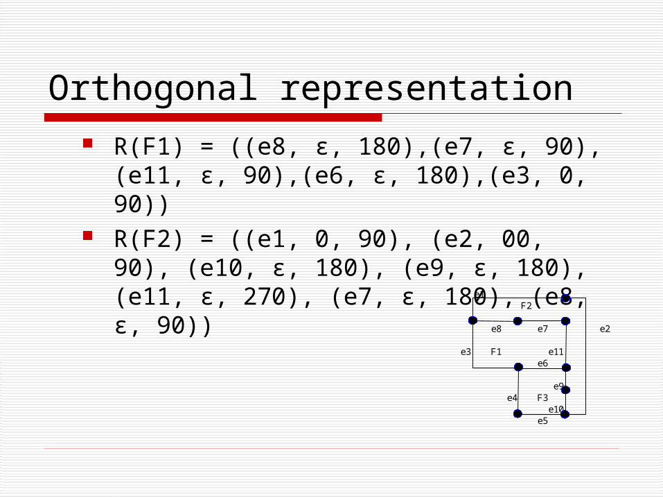
Orthogonal representation R(F1) = ((e8, ε, 180),(e7, ε, 90),(e11, ε,
90),(e6, ε, 180),(e3, 0, 90)) R(F2) = ((e1, 0, 90), (e2, 00, 90), (e10, ε,
180), (e9, ε, 180), (e11, ε, 270), (e7, ε, 180), (e8, ε, 90))
e1F2
e8 e7 e2
e3 F1 e11e6
e9e4 F3
e10e5
Orthogonal representation
Necessary properties of a orthogonal representation: (p1) There is some planer graph whose
planer representation is given by the e-fields of the list in R
(p2) For each pair of elements r and r’ in R with Er=Er’, string Sr’ can be obtained by applying bitwise negation to the reversion of Sr’
Orthogonal representation (p3) For each element r in R, define the
rotation p(r) as follows: p(r) = |Sr|0 - |Sr|1 + (2-Ar/90)
(p4) For each vertex v, the sum of the vertex angles around v given by the A-fields in R is equal to 360 degrees
Flow network
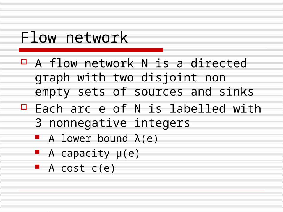
A flow network N is a directed graph with two disjoint non empty sets of sources and sinks
Each arc e of N is labelled with 3 nonnegative integers A lower bound λ(e) A capacity μ(e) A cost c(e)
Flow network
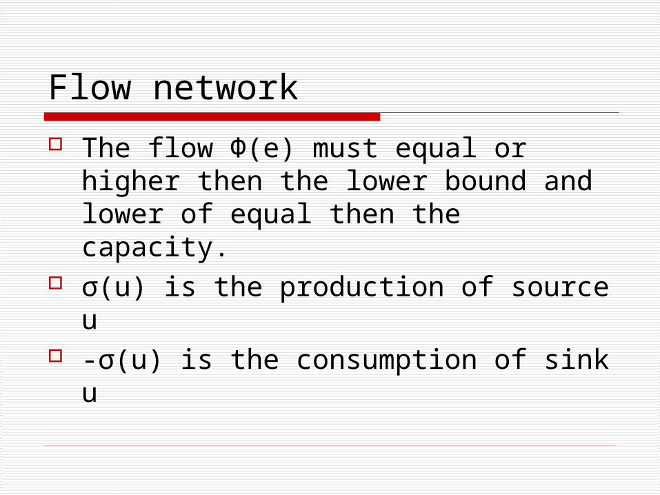
The flow Ф(e) must equal or higher then the lower bound and lower of equal then the capacity.
σ(u) is the production of source u -σ(u) is the consumption of sink u
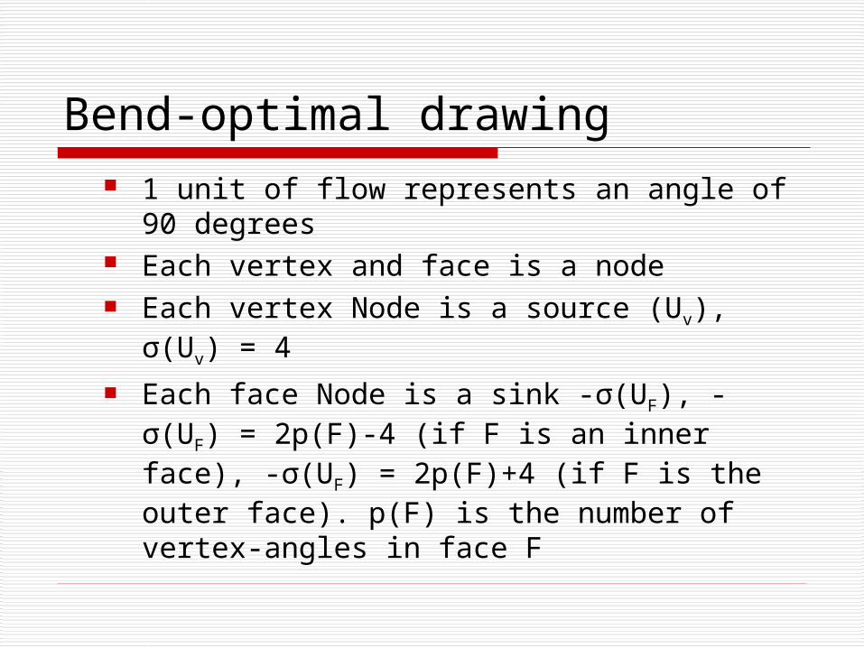
Bend-optimal drawing 1 unit of flow represents an angle of 90
degrees Each vertex and face is a node Each vertex Node is a source (Uv), σ(Uv)
= 4 Each face Node is a sink -σ(UF), -σ(UF) =
2p(F)-4 (if F is an inner face), -σ(UF) = 2p(F)+4 (if F is the outer face). p(F) is the number of vertex-angles in face F
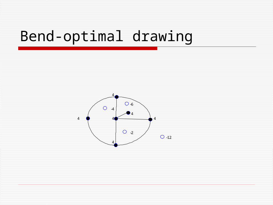
Bend-optimal drawing
4
-6-4
44 4 4
-2-12
4
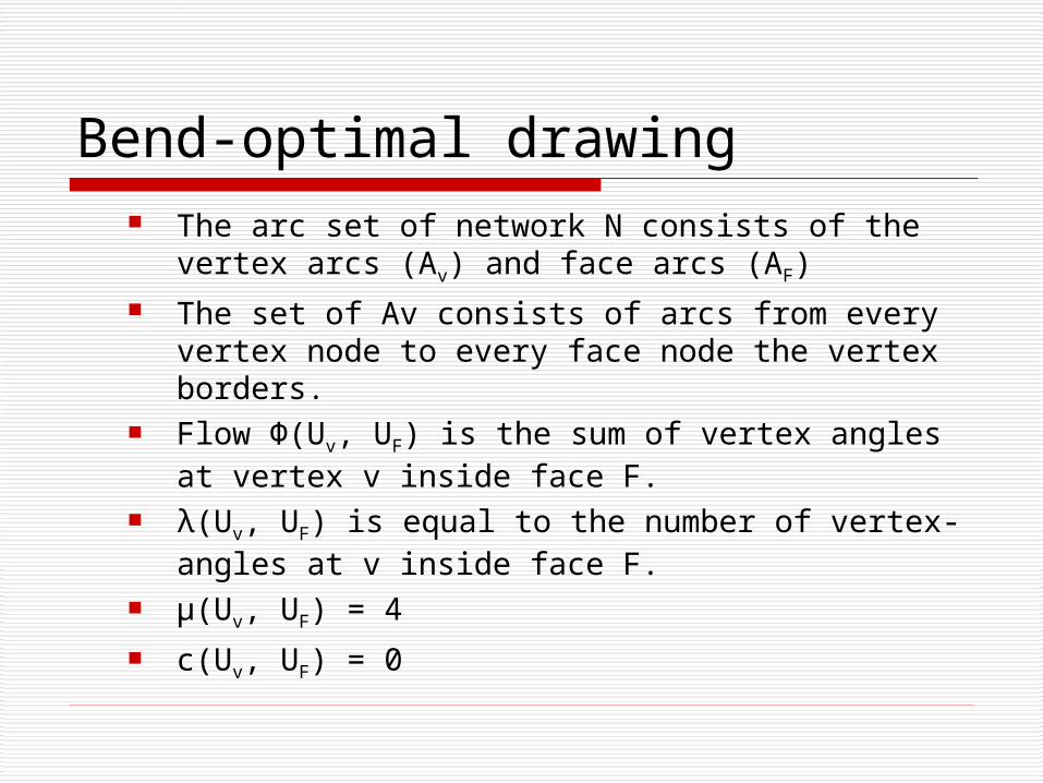
Bend-optimal drawing The arc set of network N consists of the vertex
arcs (Av) and face arcs (AF) The set of Av consists of arcs from every vertex
node to every face node the vertex borders. Flow Ф(Uv, UF) is the sum of vertex angles at
vertex v inside face F. λ(Uv, UF) is equal to the number of vertex-angles
at v inside face F. μ(Uv, UF) = 4 c(Uv, UF) = 0
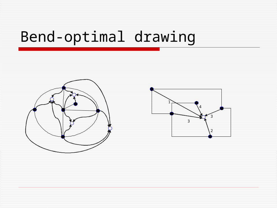
Bend-optimal drawing
14
33
2
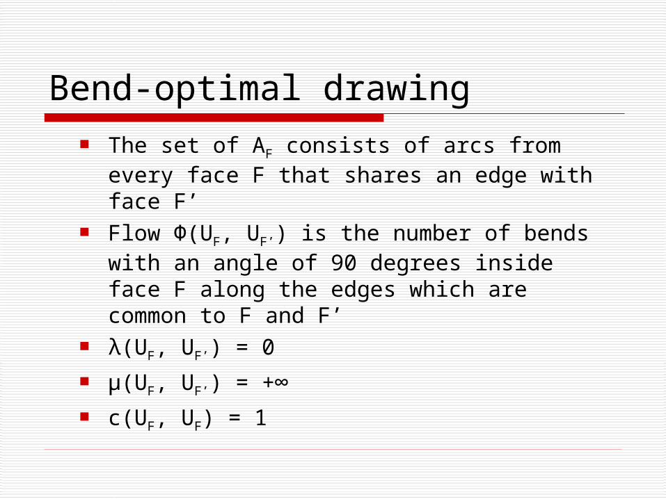
Bend-optimal drawing The set of AF consists of arcs from every
face F that shares an edge with face F’ Flow Ф(UF, UF’) is the number of bends
with an angle of 90 degrees inside face F along the edges which are common to F and F’
λ(UF, UF’) = 0 μ(UF, UF’) = +∞ c(UF, UF) = 1
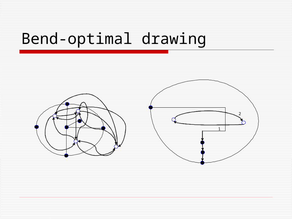
Bend-optimal drawing
2
1
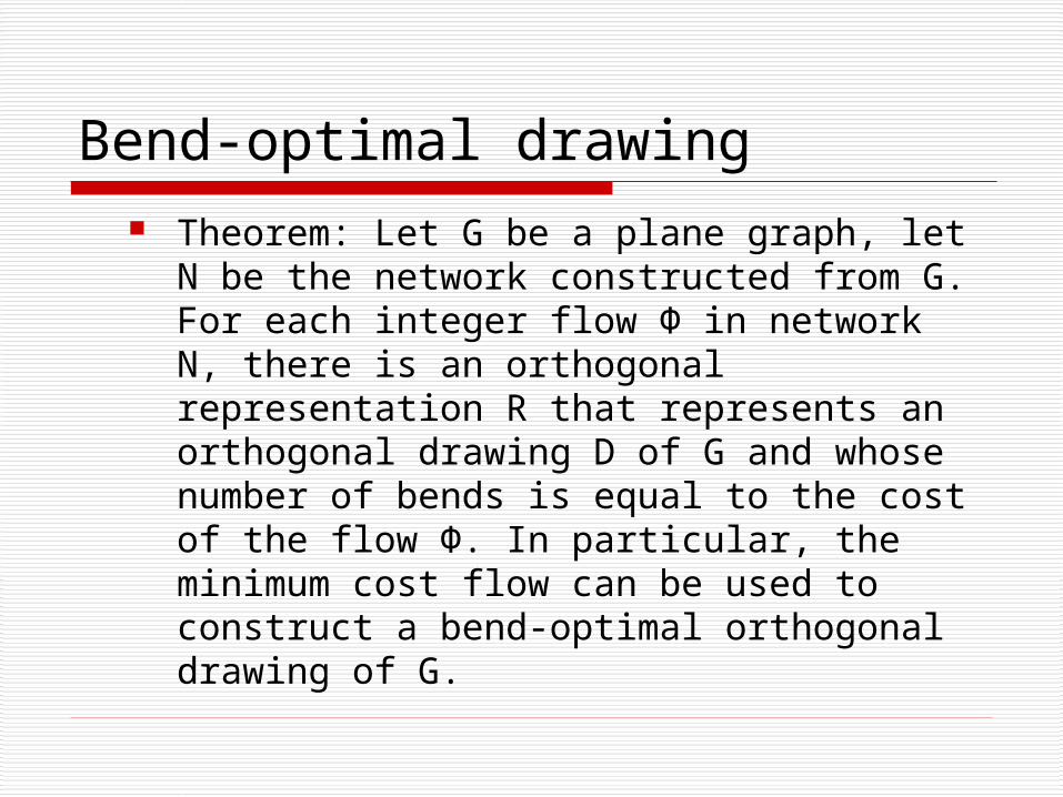
Bend-optimal drawing Theorem: Let G be a plane graph, let N
be the network constructed from G. For each integer flow Ф in network N, there is an orthogonal representation R that represents an orthogonal drawing D of G and whose number of bends is equal to the cost of the flow Ф. In particular, the minimum cost flow can be used to construct a bend-optimal orthogonal drawing of G.
Bend-optimal drawing
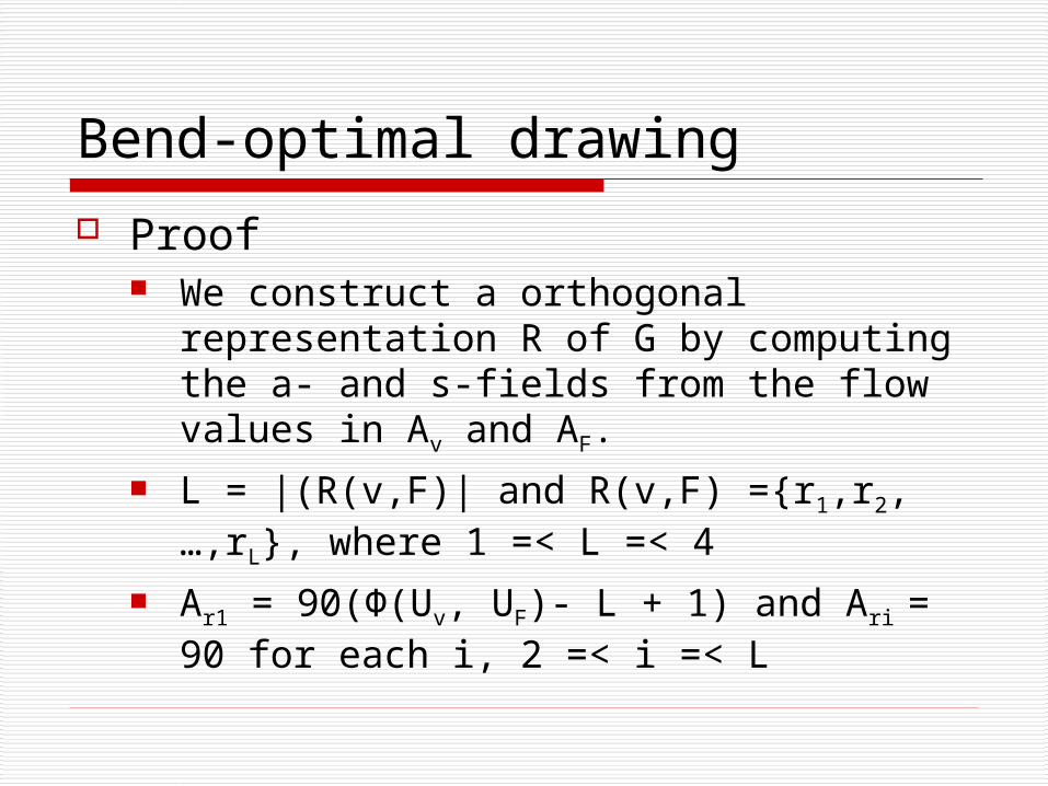
Proof We construct a orthogonal
representation R of G by computing the a- and s-fields from the flow values in Av and AF.
L = |(R(v,F)| and R(v,F) ={r1,r2,…,rL}, where 1 =< L =< 4
Ar1 = 90(Ф(Uv, UF)- L + 1) and Ari = 90 for each i, 2 =< i =< L
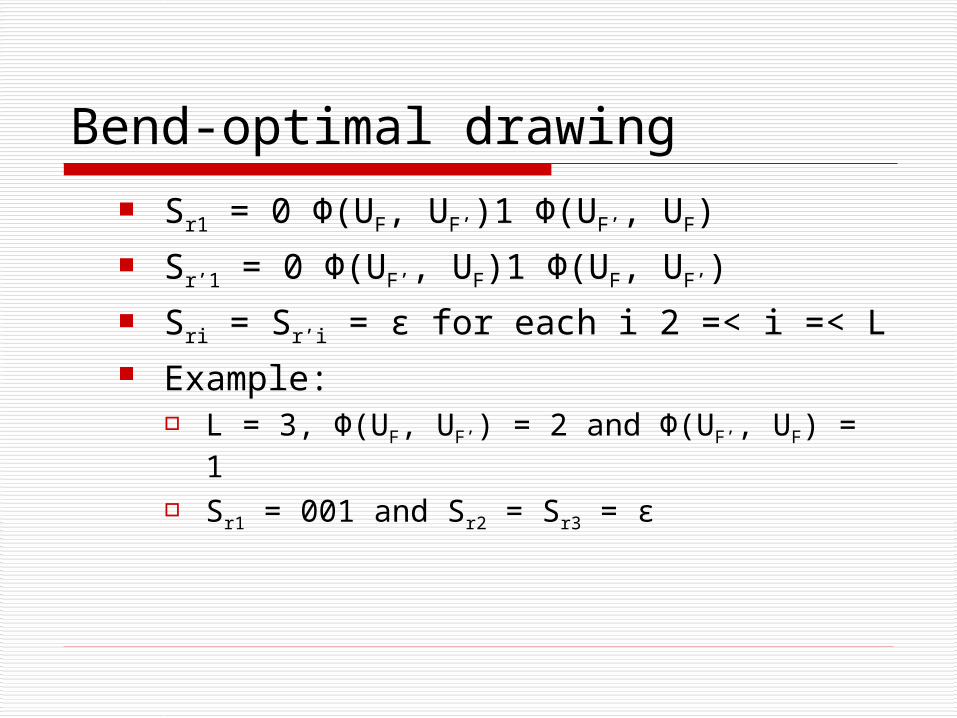
Bend-optimal drawing Sr1 = 0 Ф(UF, UF’)1 Ф(UF’, UF) Sr’1 = 0 Ф(UF’, UF)1 Ф(UF, UF’) Sri = Sr’i = ε for each i 2 =< i =< L Example:
L = 3, Ф(UF, UF’) = 2 and Ф(UF’, UF) = 1 Sr1 = 001 and Sr2 = Sr3 = ε
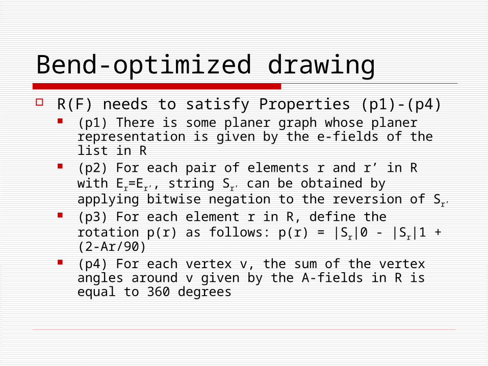
Bend-optimized drawing R(F) needs to satisfy Properties (p1)-(p4)
(p1) There is some planer graph whose planer representation is given by the e-fields of the list in R
(p2) For each pair of elements r and r’ in R with Er=Er’, string Sr’ can be obtained by applying bitwise negation to the reversion of Sr’
(p3) For each element r in R, define the rotation p(r) as follows: p(r) = |Sr|0 - |Sr|1 + (2-Ar/90)
(p4) For each vertex v, the sum of the vertex angles around v given by the A-fields in R is equal to 360 degrees
Bend-optimized drawing (p1) is automatically satisfied since we
have build R from a planar representation (p2) easily follows from the assignment of
the S-values. (p4) follows from the definition that every
source produces 4 units. (p3) Solving the equation by replacing with
the flow equations makes this satisfied. Look in the book for a more precise proof of this.
Conclusion
Garg and Tamassia have shown that the minimum cost flow problem in this specific network can be solved in time O(n7/4√(log n))

Questions?


![The DFS-heuristic for orthogonal graph drawing · The DFS-heuristic for orthogonal graph drawing ... The grid box [2,4]×[2,5] has size 3×4, area 12, and half-perimeter 7. It has](https://static.fdocuments.us/doc/165x107/60530a85bc25e65083217e51/the-dfs-heuristic-for-orthogonal-graph-drawing-the-dfs-heuristic-for-orthogonal.jpg)