Department of Psychology Loma Linda University Loma Linda, California 92350 hbetancourt@llu
Upload
trinhkhanhCategory
view
214download
0
ORO LOMA SANITARY DISTRICT 2600 GRANT AVENUE, SAN LORENZO, CA 94580
STANDARDS RESOLUTION NO. 2730
ADOPTED JANUARY 17, 1995
Revised June 2014
DIRECTORS:
Roland J. Dias, President Laython N. Landis, Vice President
Timothy P. Becker, Secretary Howard W. Kerr, Director Frank V. Sidari, Director
General Manager: Jason J. Warner
District Engineer: William D. Halsted
RCE # 68475

i
TABLE OF CONTENTS STANDARD PAGE
INTRODUCTION 1 DEFINITIONS AND ABBREVIATIONS 2 SEWER PIPE LINE 4 MANHOLES AND CASTINGS 6 PORTLAND CEMENT CONCRETE AND MORTAR 9 SEWER CONSTRUCTION AND REPAIR 10 TESTING 16 CLEANING 19 TELEVISION INSPECTION (PUBLIC SEWERS) 20 SITE CLEANUP AND RESTORATION (PUBLIC SEWERS) 21
STANDARD DETAILS
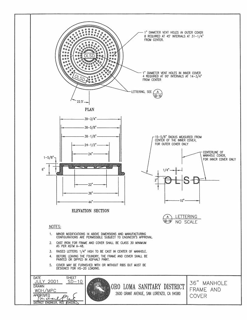
MAIN MANHOLE SD-1 OUTSIDE DROP MAIN MANHOLE ..................................................................... SD-2 INSIDE DROP MAIN MANHOLE ......................................................................... SD-3 TRUNK MANHOLE.............................................................................................. SD-4 SHALLOW MAIN MANHOLE .............................................................................. SD-5 TYPE "A" SHALLOW MAIN MANHOLE .............................................................. SD-6 CONNECTION TO TERMINAL MAIN MANHOLE ............................................... SD-7 24-inch MANHOLE FRAME AND COVER .......................................................... SD-8 24-inch MANHOLE FRAME AND COVER (BOLT DOWN) ................................. SD-9 36-inch MANHOLE FRAME AND COVER ......................................................... SD-10 BUILDING SEWER CLEANOUT TO GRADE .................................................... SD-11 CONCRETE ENCASEMENT/CAP ..................................................................... SD-12 SANITARY SEWER STORM DRAIN CROSSINGS ........................................... SD-13 UTILITY CROSSING .......................................................................................... SD-14 BUILDING SEWER/BACKWATER PREVENTION SYSTEM ............................ SD-15 TYPICAL TRENCH ............................................................................................. SD-16 PRIVATE SEWER DISCONNECT DETAILS ..................................................... SD-17 MANHOLE MODIFICATIONS ............................................................................ SD-18 MANHOLE PAD WITH RETAINING WALL ........................................................ SD-19 PIPE REPLACEMENT THROUGH EXISTING MANHOLE ................................ SD-20 FALSE BOTTOM ................................................................................................ SD-21 GRIT TRAP ........................................................................................................ SD-22 EARTHQUAKE FAULT CROSSING MANHOLE CONNECTION ....................... SD-23 2 FT. DIAMETER MANHOLE……………………………………………….………..SD-24

1
SECTION 1
INTRODUCTION 1.01 INTRODUCTION
It is the intent that these Standards apply to all sanitary sewer work, whether public or private, performed within the jurisdiction of the District unless said work is performed by the District under a separate contract and specifications. The jurisdiction of the District includes the entire sewerage system and its appurtenances from the point of connection with the building drain to the discharge terminus of the treatment plant outfall.
Changes to these Standards may be made periodically and will be available to the public and contractors at the District offices and on the District website http://engr.oroloma.org. Users of these Standards are urged to apprise themselves of all changes.
END OF SECTION 1

2
SECTION 2
DEFINITIONS AND ABBREVIATIONS 2.01 DEFINITIONS
Whenever in these Standards the following terms are used, the intent and meaning shall be interpreted as follows:
BEDDING AND SHADING - Bedding shall be defined as that material supporting the pipe. Shading shall be defined as the material surrounding and extending one foot above the top of the pipe.
BUILDING SEWER - A Building Sewer shall refer to any existing or proposed private sewer. It extends from the exterior connection of the building drain of the structure(s) to be served, to the point of connection, including the wye fitting, tee fitting, or tap, for which the District has permit authority and inspection jurisdiction, but no maintenance responsibility, to a collector sewer or main sewer, and it is subject to inspection and approval by the District, and when so approved, becomes the maintenance responsibility of the property owner.
COLLECTOR SEWER - A Collector Sewer shall mean that private sanitary sewer, including the wye fitting, tee fitting, or tap, for which the District has permit authority and inspection jurisdiction, but no maintenance responsibility, which collects sewage from more than one building sewer on the same parcel and extends to the public sewer.
CONTRACTOR - Company or individual authorized by the District to perform work by issuance of sewer permit.
DISTRICT - The Oro Loma Sanitary District of Alameda County, California.
DISTRICT BOARD - The governing body of the District.
ENGINEER - The Engineer appointed by the District acting either directly or through properly authorized agents, such agents acting within the scope of the particular duties delegated to them.
MAIN SEWER - A Main Sewer shall refer to any existing or proposed sewer dedicated to public use. It is subject to inspection and approval by the District and, when accepted, becomes the maintenance responsibility of the District.
PRIVATE SEWER - Private Sewer shall mean building sewer or collector sewer that is the property and maintenance responsibility of the property owner.
PUBLIC SEWER - Public Sewer shall mean a sewer lying within a street or

3
easement and which is controlled by or under the jurisdiction of the District.
STANDARDS - The directions, provisions, requirements and detail drawings contained herein.
STANDARD DETAILS - Detailed standard drawings of approved construction in the District contained herein.
STANDARD SPECIFICATIONS - Shall mean the "Standard Specifications", State of California, Department of Transportation, most recent edition.
TRUNK SEWER - A main sewer 18-inch or more in interior diameter.
2.02 ABBREVIATIONS ABS - Acrylonitrile Butadiene Styrene AC - Asphalt Concrete ANSI - American National Standards Institute ASTM - American Society of Testing Materials AWWA - American Water Works association CIP - Cast Iron Pipe DIP - Ductile Iron Pipe HDPE - High Density Polyethylene PVC - Polyvinyl Chloride UPC - Uniform Plumbing Code VCP - Vitrified Clay Pipe
END OF SECTION 2

4
SECTION 3
SEWER PIPE LINE 3.01 GENERAL
All sewer construction materials proposed to be used must be new first quality and approved for use by the District prior to start of construction. Whenever requested by the District, the Permit holder shall submit properly authenticated documents or other satisfactory proof of compliance with these standards.
3.02 PIPE MATERIAL
A. CLAY PIPE - Clay Pipe shall be Vitrified Clay (VC) pipe and fittings, extra strength, bell and spigot or plain end pipe. The pipe and fittings shall conform in all respects to the most recent ASTM designations.
1. Joints - Joints for VC pipe shall be either compression type joints or
a mechanical type compression coupling consisting of a rubber coupler which is connected to the VC pipe with stainless steel compression bands. The materials comprising joints and couplings shall conform in all respects to the most recent ASTM designations.
B. ABS PIPE - Acrylonitrile Butadiene Styrene (ABS) pipe and fittings shall
be solid wall pipe and conform in all respects to the most recent ASTM designations.
1. Pipe Wall Thickness - Private Sewer SDR 35 Public Sewer SDR 23.5 2. Joints - Joints for ABS pipe shall be solvent cement, solvent weld,
or elastomeric gasket bell and spigot. C. PVC - Polyvinyl Chloride (PVC) pipe and fittings shall be solid wall pipe
conform in all respects to the most recent ASTM designations.
1. Pipe Wall Thickness - Private Sewer SDR 35 Public Sewer SDR 26
2. Joints - Joints for PVC pipe shall be solvent cement, solvent weld,
or elastomeric gasket bell and spigot. D. HDPE - High Density Polyethylene (HDPE) pipe shall be solid wall and
shall meet the requirements for Type III, Class B or C, Category 5, Grade P34 Material as described in ASTM D1248. The pipe shall contain no recycled compound except that generated in the manufacturer's own plant

5
from resin of the same specification from the same raw material pipe. HDPE pipe shall only be used for sewer replacement by insertion process except as approved by the Engineer.
1. Pipe Wall Thickness - Private Sewer SDR 17 Public Sewer SDR 17 2. Joints - Joints for HDPE Pipe shall be butt-fusion welded. All joints
shall use materials and procedures as recommended by the pipe manufacturer. The inside bead shall be removed after the pipe is fused.
3. Color - Inner wall shall be white, light green, light red, or natural.
Black, yellow, and light purple are not acceptable. The outside has the same color requirements but does not have to match the color of the inside wall.
E. IRON PIPE - Cast Iron (CI) and Ductile Iron (DI) pipe shall not be used for
public sewer without consent of the District Engineer. CI pipe for private sewers shall be soil pipe service weight, Class SV, or extra heavy, Class XH. DI pipe for private sewers shall be thickness Class 51 for 4-inch pipe and Class 50 for larger pipe.
1. Joints - Joints for Iron Pipe shall be standard integral mechanical
joint of the same manufacture as the pipe, Smith-Blair or Dresser type couplings, sleeve type coupling, compression coupling consisting of a rubber coupler which is connected to the pipe with stainless steel compression bands, Tyton type joints, or approved equal, all installed as recommended by the manufacturer.
F. Other Materials - Other pipe materials, joint couplings and pipe fittings
may be used provided written approval of the District has been granted prior to installation. The District may require documentation that the pipe material being used is suitable for the conditions expected to be encountered in the proposed installation.
END OF SECTION 3

6
SECTION 4
MANHOLES AND CASTINGS 4.01 MANHOLES
All manholes shall be watertight structures with concentric cones and precast reinforced concrete barrel sections and shall have steps from top to bottom. Manholes shall conform to the appropriate Standard Detail.
Manholes shall have a forty-eight inch (48-inch) interior diameter for all sewers except that sixty inch (60-inch) interior diameter manholes are required for all trunk sewers twenty-one inch (21-inch) or larger in diameter.
A. CAST-IN-PLACE MANHOLE BASE BLOCK:
The base block shall be Class "A" concrete per the Standard Specifications and in accordance with the design shown on the Standard Details.
Cast-in-place concrete shall be placed only on dry, firm undisturbed ground or on 3/4-inch crushed rock placed on undisturbed ground, or as directed by the Engineer. If the pour is on filled ground, the ground shall be compacted to a 95% relative compaction. The concrete shall be placed with a continuous pour deposited in such a manner that segregation of material does not occur. Once deposited, it shall be consolidated so as to secure a dense watertight mass.
Internal vibrators will be required for consolidation of concrete on all poured manhole base blocks. An approved metal form ring shall be on the job site so that a level keyed slot may be formed in the fresh concrete to receive the first precast section. (As an alternative to the form ring, the first precast section of the manhole may be set plumb into fresh concrete.)
When the sewer pipe has been laid continuously through the manhole and after the concrete has set, the top half of the sewer pipe shall be removed to within one (1) inch longitudinally of the inside wall of the precast section and the cut finished with mortar as specified by the Engineer.
The width of opening at the top of base block shall be the inside diameter of the pipes in the manhole.
In angle point manholes and in junction manholes, the pipes shall be joined by smooth curves, warped to conform with the lower half of the pipe. In all cases, the upper portion of the manhole channel from the mid-point of the pipes in the manhole to the top of the base block shall be

7
constructed vertically.
When the manhole channel is not completed in the original pour, it shall be finished smooth by use of mortar with type as specified by the Engineer. Before application of the mortar, the existing concrete surface shall be thoroughly cleaned and roughened to secure a firm bond. All channels shall be troweled smooth so that a smooth uninterrupted surface is achieved. The top of the base block shall be troweled to slope towards the channel at an approximate slope of one (1) inch in ten (10) inches.
B. MANHOLE BARREL AND PRECAST BASE BLOCK:
The manhole barrel shall be composed of precast concrete sections. These sections shall be installed plumb and aligned so that the steps are in a straight vertical line. Unless otherwise required by the Engineer, the steps shall be aligned horizontally forty five (45) degrees away from the direction of the flow of the sewer main on the downstream side.
Precast concrete barrel sections shall be in accordance with the Standard Details and shall conform to the requirements of ASTM Designation C-478 except that Type II or Type V Portland Cement shall be used. The cone section shall be concentric unless concentric is specified by the Engineer.
Unless otherwise directed by the Engineer, manholes will be constructed with concentric cone section per Standard Details. In these cases, the neck rings shall be installed after the street section has been completed.
Joints between precast sections shall have "Ram-Nek", or equal, flexible plastic gasket installed between the tongue and groove joint to make a watertight joint. After the shaft is in place, the joint shall be trimmed smooth with a sharp tool on the inside of the manhole and the outside seam shall be mortared. After the mortar has set wrap all joints with “RUB’R-NEK”, or equal, joint wrap before backfilling.
C. MANHOLE STEPS:
Steps shall be installed in the manhole cone and barrel sections by the manhole manufacturer before being shipped to the job site unless the manhole is specified by the Engineer to be without steps.
Steps for manholes shall be made of copolymer polypropylene that encapsulates a 1/2-inch grade 60 steel reinforcing rod. Steps shall have a non-slip tread surface and conform with ASTM Designation C-478, Paragraph 11.
D. MANHOLE CHANNEL: 2. Construction: The manhole channel shall be formed from Class 'A'

8
concrete and shall be troweled smooth, smooth enough to not stop any paper or debris. The channel shall provide a smooth transition between varying pipe diameters. The radius of the bottom of the channel shall match the inlet and outlet pipes.
1. Channel slope through manhole: The slope through the manhole
shall be designed to maintain a constant velocity through the system with a minimum flow of 2 ft/sec, while taking into account changing directions and materials. Slope shall be approved by the Engineer.
4.02 CASTINGS
A. Castings shall conform to the shape, weights and dimensions shown in the Standard Details.
B. Castings shall be dipped or painted with an asphalt paint which will form a
tough, tenacious, nonscaling coating which does not have a tendency to become brittle when cold or sticky when hot.
C. Manhole frame and cover assemblies shall be machined so that the cover
will seat evenly and firmly in the frame.
D. In paved and unpaved areas, unless otherwise specified by the Engineer, a concrete collar shall be poured around the frame, adjusting ring, and cone as shown in the Standard Details.
END OF SECTION 4

9
SECTION 5
PORTLAND CEMENT CONCRETE AND MORTAR
5.01 PORTLAND CEMENT CONCRETE
Portland cement concrete, materials, mixing, handling and curing shall conform to the requirements of Section 90 of the Standard Specifications for Class "A" concrete unless otherwise specified.
A. Portland cement used shall be Type II or Type V Portland Cement.
B. Calcium chloride, not in excess of two (2) percent by volume, will be
permitted when, in the Engineer's opinion, circumstances warrant its use. 5.02 MORTAR AND GROUT
Mortar and grout shall consist of one (1) part Type II or Type V Portland Cement and one and one-half (1½) parts sand. Sufficient water shall be added and thoroughly mixed to provide a plastic, workable and cohesive mixture for mortar and shall be further diluted with water to flow readily for grout.
Rapid-hardening hydraulic cement shall be used when required by the Engineer. The concrete mix shall conform to the ASTM requirements for Packaged, Dry, Rapid-Hardening Cementitious Materials for Concrete Repairs.
END OF SECTION 5

10
SECTION 6
SEWER CONSTRUCTION AND REPAIR 6.01 GENERAL
Sewer pipe lines and appurtenances shall be constructed or repaired as shown on the Standard Details or ordered by the District Engineer and in accordance with these Standards.
6.02 SEWER PIPE LINES
A. Public sewers shall have a minimum inside diameter of eight (8) inches.
B. Private sewers shall have a minimum inside diameter as indicated below:
1. Building sewer for a single family residence: four (4) inches. 2. Building sewer for a multiple family residence or nonresidential
building: six (6) inches. 3. Collector sewers accepting discharge from two or more building
sewers: six (6) inches. 4. Force mains in pumped systems: four (4) inches unless otherwise
approved by the Engineer.
C. Sewers shall be designed and constructed to the maximum slope possible consistent with good design practices but in no case less than the minimum listed below, measured in feet per foot (inch/foot) unless authorized by the Engineer:
Diameter Plastic Pipe All Other Pipe min. slope min. slope 4-inch 0.01 (1/8) 0.01 (1/8) 6-inch 0.004 0.005 (1/16) 8-inch 0.003 0.0035 10-inch 0.002 0.0025 12-inch 0.0017 0.0020 15-inch 0.0012 0.0015 18-inch 0.0010 0.0012 >18-inch 0.0010 0.0010
D. Minimum depth of cover from top of pipe to finished grade for sewers is shown in the Standard Details.

11
E. Sewers to be abandoned shall be securely closed at all pipe ends by an approved cap or at manhole entries, by a watertight plug of concrete, or brick and mortar, not less than two (2) feet thick. When building sewers are abandoned, they will be capped with an approved fitting at the main sewer as directed by the Engineer.
6.03 BACKWATER PREVENTION SYSTEM
See SD-15 6.04 EXCAVATION
Excavation for sewers shall be made by open trenching except where a trenchless method is acceptable to the District. Attention is directed to SD-15 for pipe trench details.
Prior to any excavation for sewer work in a public right-of-way the Permit holder shall have available at the job site evidence of permits for work in State or County roads and/or City streets. A CAL/OSHA permit is also required for all excavation work and must be provided upon request. Contractor shall solely be responsible for meeting all CAL/OSHA requirements, including but not limited to sheeting, shoring, and bracing, or equivalent method for the protection of life and limb in trenched and open excavations.
Where solid rock is encountered, it shall be removed to a minimum of four (4) inches below the outside bottom of the pipe and the trench backfilled with bedding material as specified in this section.
Where mud or other soft or spongy material incapable of proper pipe support is encountered, all such material shall be excavated and replaced as shown in SD-16.
The Permit holder shall furnish, install and operate all necessary pumps and appurtenant equipment to keep all trenches and other excavations reasonably free from water during construction and shall dispose of the water so as not to cause injury to public or private property or to create a nuisance or menace to the public.
6.05 BEDDING AND SHADING
Attention is directed to the Standard Details for applicable pipe bedding and shading details.
Sand bedding and shading shall only be used when approved by the District Engineer and shall conform to the requirements for “Sand Bedding” under Section 19 of the Standard Specifications.

12
Granular bedding and shading, free of deleterious substances, shall be of either of the following gradations:
PEA GRAVEL
(only used with permission of the District Engineer) Sieve Size % Passing 3/8-inch 100 #4 40-65 #8 5-35 #30 0-10
3/4-inch CRUSHED ROCK Sieve Size % Passing 1-inch 100 3/4-inch 90-100 1/2-inch 30-60 3/8-inch 0-20 #4 0-5 6.06 BACKFILL AND COMPACTION
Backfill material shall be placed and consolidated in such a manner as to prevent damage to any sewer, roadbed, road surface, utility or private property.
Trench backfill shall be compacted to a minimum of 95% or to the requirements of the agency having jurisdiction and in such a manner as to prevent settlement.
6.07 UTILITIES AND STORM DRAINS
A. RELOCATIONS: When new utility pipe/conduit or storm drain conflicts with the grade of an existing sewer line, the new facility shall be raised or lowered, if possible, to miss the sewer line. If this is not possible, the sewer line shall be relocated in accordance with these standards.
B. REPAIRS:
During the course of installation of new utility pipe/conduit or storm drain, repairs to damaged sewers shall be made with matching pipe in accordance with the Standard Details.
C. STORM DRAIN CROSSING:
When storm drain pipe/conduit passes under or over an existing sewer, or a new sewer line crosses under an existing storm drain pipe/conduit, it shall be necessary to install PVC pipe for the sewer at such crossings, in accordance with the Standard Details.

13
6.08 CONNECTIONS TO EXISTING SEWERS
It shall be the responsibility of the contractor to determine the exact location and depth of existing sewers prior to the laying of any sewer pipe. The contractor shall also determine the elevation of the building drain outlet to be connected and whether the required grade can be maintained between the outlet and the main sewer prior to construction of any portion of the building and/or collector sewer.
A. PRIVATE LATERAL AND COLLECTOR CONNECTIONS:
1. EXISTING MANHOLES: No lateral connections shall be made to
existing sewer main manholes except as approved and directed by the District Engineer.
2. NEW MANHOLES: Where the District Engineer approves
connection to an existing sewer by construction of a new manhole, such construction shall conform to the Standard Details.
3. SPLICES: Connections to sewer mains may be made by splicing
standard branch fittings, of the same material into the existing main. Connection between new and existing pipe shall be made with stainless steel mechanical type compression coupling with external shear band or as directed by the Engineer. The last connection on a terminal line shall be a wye fitting.
The trench from the connection shall extend under the main and the soil under the main shall be removed and replaced per SD-16 to provide a firm base for the new connection.
4. TAPS: The use of taps employing core drilling techniques and specially designed fittings for connection to sewer mains is acceptable. If the sewer main is damaged during tapping operations, the contractor shall remove the damaged section and install a branch fitting or repair the damage as directed by the Engineer. A tap may not be used at the last fitting on a terminal run.
The trench from the connection shall extend under the main and the soil under the main shall be removed and replaced per SD-16 to provide a firm base for the new connection.
B. PUBLIC SEWER CONNECTIONS: There shall be no public connections
to existing sewers utilizing splices or taps.

14
1. EXISTING MANHOLES: Connections to existing manholes may require rebuilding the manhole to meet the standard details. Penetrations into existing manholes shall be done by coring.
2. NEW MANHOLES: Where the District Engineer approves
connection to an existing sewer by construction of a new manhole, such construction shall conform to the Standard Details.
6.09 REPAIRS TO EXISTING SEWERS
It shall be the responsibility of the contractor to verify the location and depth of the repair before excavating. It shall be the responsibility of the contractor to possess or obtain all necessary permits and licenses prior to commencing work. Copies of permits shall be submitted to the Engineer. The contractor will observe all applicable safety and health regulation in prosecuting the work. All repair work shall receive an inspection by the Engineer prior to covering the repaired pipe. The final inspection will take place via CCTV after the pipe is loaded with the trench backfill.
A. SEWAGE FLOW:
The contractor shall contain within or bypass to the sanitary sewer system all sewage flow in a manner to limit contamination of the surrounding area and maintain a stable foundation for repair pipe bedding. 1. All flow control or diversion systems shall be submitted to the
Engineer for review and approval. 2. All flow control or diversion systems shall be sized with sufficient
capacity to accommodate the maximum dry weather flow and to provide additional capacity for unexpected events or rainstorms.
3. If pumped bypass systems is used, Contractor shall provide
emergency standby pump(s) capable of maintaining the bypass.
B. GROUNDWATER: The contractor shall control groundwater encountered in the excavation to maintain a stable foundation for repair pipe bedding.
C. UNSUITABLE MATERIAL: The contractor shall remove from the excavation all material deemed unsuitable by the District and replace it with 3/4-inch Crushed Rock, to a minimum 12-inch depth, to provide a stable foundation for pipe bedding. The 3/4-inch crushed rock shall be wrapped in filter fabric.
15
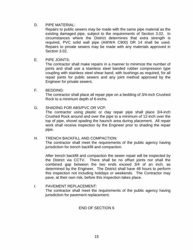
D. PIPE MATERIAL: Repairs to public sewers may be made with the same pipe material as the existing damaged pipe, subject to the requirements of Section 3.02. In circumstances where the District determines that extra strength is required, PVC solid wall pipe (AWWA C900) DR 14 shall be used. Repairs to private sewers may be made with any materials approved in Section 3.02.
E. PIPE JOINTS:
The contractor shall make repairs in a manner to minimize the number of joints and shall use a stainless steel banded rubber compression type coupling with stainless steel shear band, with bushings as required, for all repair joints for public sewers and any joint method approved by the Engineer for private sewers.
F. BEDDING:
The contractor shall place all repair pipe on a bedding of 3/4-inch Crushed Rock to a minimum depth of 6-inchs.
G. SHADING FOR ABS/PVC OR VCP:
The contractor using plastic or clay repair pipe shall place 3/4-inch Crushed Rock around and over the pipe to a minimum of 12-inch over the top of pipe, shovel spading the haunch area during placement. All repair work shall receive inspection by the Engineer prior to shading the repair pipe.
H. TRENCH BACKFILL AND COMPACTION:
The contractor shall meet the requirements of the public agency having jurisdiction for trench backfill and compaction. After trench backfill and compaction the sewer repair will be inspected by the District via CCTV. There shall be no offset joints nor shall the combined gap between the two ends exceed 3/4 of an inch, as determined by the Engineer. The District shall have 48 hours to perform this inspection not including holidays or weekends. The Contractor may pave, at their own risk, before this inspection takes place.
I. PAVEMENT REPLACEMENT: The contractor shall meet the requirements of the public agency having jurisdiction for pavement replacement.
END OF SECTION 6

16
SECTION 7
TESTING 7.01 GENERAL
All acceptance and approval tests shall be done in the presence of the Engineer.
Any portion of the sewer found not to be in conformance with these Standards must be corrected by the contractor. Sewers so corrected shall be re-tested and inspected in accordance with the requirements of these Standards and at the sole expense of the Contractor.
7.02 TESTS FOR OBSTRUCTIONS
The testing of all plastic sewer lines include testing by mandrel (95%). The contractor shall provide necessary labor and equipment for the test at his sole expense.
7.03 TESTS FOR LEAKAGE
Leakage tests for final acceptance or approval of the sewers and manholes shall be performed after all compaction work is complete, after all other utilities are in place, and grading work is complete. In paved areas this test will normally be performed immediately after final compaction and prior to placement of paving material. The program of testing must fit the conditions as mutually determined by the Engineer and the contractor. The contractor shall furnish all labor, tools, plugs and equipment necessary to make the tests and to perform any work incidental thereto at his sole expense. The contractor shall take all necessary precautions to prevent any damage or dislocation of any kind while the pipelines or their appurtenances are being tested. He shall, at his own expense, correct any leakage and repair any damage to the pipeline and its appurtenances or to any structures resulting from or caused by these tests.
A. SEWER LINES
The Contractor shall plug and brace the ends of the sewer lines being tested and furnish air, from a compressor with adequate capacity to maintain four (4) pounds per square inch gage (psig) pressure in the line under test, through gauging and testing equipment furnished and operated by the contractor. After an internal pressure of 4.0 psig has been maintained for approximately two minutes, the supply of air shall be disconnected and the District will then accurately determine the time for loss of one (1) psig, from three and one-half (3½) to two and one-half (2½) psig. The minimum acceptable time for loss of one (1) psig shall be determined by using the following table:

17
MAXIMUM SECONDS PER LENGTH OF SIZE OF PIPE X LINEAR FOOT OF PIPE TEST (minutes) 4-inch 0.17 2 6-inch 0.39 3 8-inch 0.70 4 10-inch 1.09 5 12-inch 1.58 6 15-inch 2.48 7 18-inch 3.56 9 21-inch 4.85 11 24-inch 6.34 13
When a combination of more than one pipe size is under test, the maximum test time for the larger pipe shall apply. If the time for the loss of one (1) psig is less than computed by using the above schedule, the contractor shall make such repairs as are necessary to the satisfaction of the Engineer to eliminate the excessive leakage. The repaired section of pipe shall then be retested and subjected to all other approval tests and cleaning requirements.
B. MANHOLES
Test using air whenever possible prior to backfilling to assist in locating leaks. Make joint repairs on both outside and inside of joint to ensure permanent seal. Test manholes with manhole frame set in place. When unsatisfactory test results are achieved, repair manhole and retest until result meets criteria; repair visible leaks regardless of quantity of leakage. Vacuum test in accordance with ASTM C1244 and as follows: Plug pipe openings; securely brace plugs and pipe: Inflate compression band to effect seal between vacuum base and structure; connect vacuum pump to outlet port with valve open; draw vacuum to 10 inches of Hg; close valve; start test. Test:
1. Determine test duration for manhole from the following table: VACUUM TEST TABLE Manhole Diameter Test Period 4 feet 60 seconds 5 feet 75 seconds 6 feet 90 seconds

18
2. Record vacuum drop during test period; when vacuum drop is greater than 1 inch of Hg during test period, repair and retest manhole; when vacuum drop of 1 inch of Hg does not occur during test period, discontinue test and accept manhole.
3. When vacuum test fails to meet 1 inch Hg drop in specified
time after repair, repair and retest manhole.
END OF SECTION 7

19
SECTION 8
CLEANING 8.01 GENERAL
After the sewers have satisfactorily passed the tests required in Section 7 and all structures are complete, the Contractor, in the presence of the Engineer, shall clean each section of the sewer. Contractor will be responsible for the clean up to the property Owner's and District's satisfaction in the event that the cleaning causes any discharge or backup of water or sewage into a building, residence, or onto the ground; all costs shall be the Contractor's exclusively. Contractor shall clean the sewer in the following manner:
A. SEWERS SIX (6) INCHES THROUGH TWELVE (12) INCHES IN
DIAMETER: Cleaning shall be completed with the use of hydraulically propelled, high-velocity jet (hydrocleaning) equipment. The equipment shall have a selection of four or more high-velocity nozzles. The nozzles shall be capable of producing a scouring action from 15 to 45 degrees in all size lines designated to be cleaned. The range of water pressure shall be both sufficient enough to completely clean the sewer, yet gentle enough not to displace or damage the sewer.
As the debris is pulled to the manhole with the hydro it shall be removed and not allowed to flush downstream.
B. SEWERS FIFTEEN (15) INCHES IN DIAMETER AND LARGER:
The Engineer shall visually inspect the sewer and if in his opinion cleaning is necessary, the Contractor shall clean the sewer to the satisfaction of the Engineer utilizing the methods required by the Engineer. District may clean the sewer in these sizes at Contractor's request and at his expense.
C. FOUR (4) INCH AND SIX (6) INCH BUILDING SEWERS:
When in the opinion of the Engineer, the sewer is not clean it shall be flushed or otherwise cleaned so as to properly serve its intended function. If debris is flushed into the District main, the District main shall be cleaned to the next downstream manhole and the debris removed.
END OF SECTION 8

20
SECTION 9
TELEVISION INSPECTION (PUBLIC SEWERS)
8.01 GENERAL
Television inspection of main sewers may, when so required by the Engineer, be conducted with District television equipment operated by District crews.
8.02 EXECUTION
Television inspection shall be conducted only after final air testing in conformance with Section 7, and after cleaning in conformance with Section 8.
Any portion of the sewer found not to in conformance with these Standards must be corrected by the Contractor. Sewers so corrected shall be re-tested and inspected in accordance with the requirements of these Standards at no additional cost to the District. 1. Utilize cameras specifically designed and constructed for closed-circuit
sewer line inspection. Utilize camera equipment with pan and tilt capability to view each lateral connection at multiple angles.
2. Utilize camera capable of moving both upstream and downstream;
minimum 1,000 feet horizontal distance with one setup; direct reading cable position meter.
3. Inspection shall be recorded upon a DVD in a format able to be read on a
standard computer without installing any software and submitted to the Engineer.
END OF SECTION 9

21
SECTION 10
SITE CLEANUP AND RESTORATION (PUBLIC SEWERS)
10.01 GENERAL
A. Surplus pipeline material, tools, remaining material from site preparation, etc., shall be removed by the Contractor, and all dirt, broken pavement, rubbish and excess earth from excavation shall be hauled to a legal and approved dump site by the Contractor and the construction site left clean, to the satisfaction of the Engineer.
B. Replaceable items such as fences, signs, landscaping, etc., requiring
removal during construction operations must be replaced in kind by the Contractor at his expense. Any driveway areas or other improvements requiring removal and/or excavation will be restored to a condition equivalent to their original condition all to the satisfaction of the Engineer.
C. On District contract projects and repairs, the value of and responsibility for
damage to objects that cannot be replaced in kind must be negotiated between the Contractor and the Engineer prior to the removal of those objects.
END OF SECTION 10

SECTION 11
STANDARD DETAILS