
Orion LL-6000 Liquid Laundry Supply...
13
P/N 20-07842-00 Rev. D © Hydro Systems Company, Inc. 2015 HydroSystemsCo.com Toll Free: 1.800.543.7184 1 Reference Manual Installation and Operation Preface This manual has been written and illustrated to present the basic installation, operation and servicing instructions of the Orion LL-6000 Chemical Management System. Guidelines will be suggested in reference to the preferred method of installation, however, the variety of equipment and the surrounding environment will dictate the actual installation of the Orion LL- 6000. Orion LL-6000 Liquid Laundry Supply Dispenser Online and downloadable Product Manuals and Quick Start Guides are available at www.HydroSystemsCo.com Please check online for the latest version of this Reference Manual. ! WARNING/ADVERTENCIA: These installation, operation and servicing instructions are for use by qualified personnel only. The Orion LL-6000 is intended to be installed by experienced installers, in accordance with all applicable electrical and plumbing codes. All laundry machine and dispenser power must be disconnected during installation and/or any time the dispenser cabinet is opened. All safety instructions and important remarks must be followed at all times!
Transcript of Orion LL-6000 Liquid Laundry Supply...

P/N 20-07842-00 Rev. D © Hydro Systems Company, Inc. 2015 HydroSystemsCo.com Toll Free: 1.800.543.7184 1
Reference Manual Installation and Operation
Preface
This manual has been written and illustrated to present the basic installation, operation and servicing instructions of the Orion LL-6000 Chemical Management System. Guidelines will be suggested in reference to the preferred method of installation, however, the variety of equipment and the surrounding environment will dictate the actual installation of the Orion LL- 6000.
Orion LL-6000 Liquid Laundry Supply Dispenser
Online and downloadable Product Manuals and Quick Start Guides are available at www.HydroSystemsCo.com
Please check online for the latest version of this Reference Manual.
!WARNING/ADVERTENCIA:These installation, operation and servicing instructions are for use by qualified personnel only. The Orion LL-6000 is intended to be installed by experienced installers, in accordance with all applicable electrical and plumbing codes. All laundry machine and dispenser power must be disconnected during installation and/or any time the dispenser cabinet is opened. All safety instructions and important remarks must be followed at all times!

P/N 20-07842-00 Rev. D © Hydro Systems Company, Inc. 2015 HydroSystemsCo.com Toll Free: 1.800.543.7184 2
Table of Contents
Theory of Operation System Overview ...........................................................................................................................3 Features .........................................................................................................................................4
Mechanical Installation Pump Module .................................................................................................................................5 Control Module ...............................................................................................................................6 Supply Tubing ................................................................................................................................6
Electrical Installation Mounting and Connecting Machine Interface (MI) .........................................................................7 Compatible Controllers .......................................................................................................8 Supply Trigger Wiring ...........................................................................................................8 “Event Mode” Wiring ...........................................................................................................9 Signal Voltage ......................................................................................................................9 Control Module Installation ...........................................................................................................9
Programming & Maintenance Calibrate Pumps .................................................................................................................10 Maintenance .................................................................................................................................10 Tube Replacement .............................................................................................................10 Tube Lubrication ................................................................................................................10 Periodic Cleaning ...............................................................................................................10
Troubleshooting Problems and Solutions ...............................................................................................................11 Circuit Breaker Reset .........................................................................................................12 Trigger Signal Test ..............................................................................................................12 Repair Procedures ..............................................................................................................12 Washer Wiring – Contacts for Manufacturers ..............................................................................12
Specifications and Limited Warranty General Specifications .................................................................................................................13 Limited Warranty ..........................................................................................................................13 Limitation of Liability ....................................................................................................................13

P/N 20-07842-00 Rev. D © Hydro Systems Company, Inc. 2015 HydroSystemsCo.com Toll Free: 1.800.543.7184 3
System Overview
The ORION LL-6000 system dispenses liquid laundry chemicals directly from the shipping containersinto a commercial laundry washer. All product additions are made automatically. Multiple modesof operation allow for maximum flexibility in washer application. This makes the ORION LL-6000suitable for use with any commercial laundry washer.The ORION LL-6000 system consists of three components (and an optional Flush Manifold): • The Machine Interface module accepts the washer signals and converts them to safe, low-voltage inputs. • The Control Module provides a timesaving menu display system to aid program setup. • The Pump Module provides heavy duty, high capacity peristaltic pumps for product transfer and provides an interface for the optional Flush Manifold. • The Optional Flush Manifold —not shown—provides an alternate means of chemical transfer to the laundry machine. In flush configuration, the Orion LL-6000 is a complete, integrated water flush chemical management system.
Figure 1 Orion LL-6000 Liquid Laundry Supply Dispenser System Overview
Theory of Operation
P/N 20-07842-00 Rev. D © Hydro Systems Company, Inc. 2015 HydroSystemsCo.com Toll Free: 1.800.543.7184 4
Features
Rugged Construction Each Orion LL-6000 features a durable stainless steel pump cabinet, and reliable, heavy-duty, high capacity pump motors.
Flexible Mounting The ORION LL-6000 can be tailored to your location, taking advantage of the unique modular construction.Now you can put your pumps where you need them, close to the product, and put the controllerconveniently on the washer.
Fast Setup The ORION LL-6000 uses modern technology to reduce setup time.
Use On Any Washer The ORION LL-6000 has all the modes required to work with any commercial washer that youencounter. The unit can be used with programmable washers, card, chart, or microprocessor controlledfixed cycle washers–even with washers lacking any dedicated supply signals.
Customized Formulas You may program and select up to 20 different chemical formulas, maximizing the effectiveness of your chemicals.
High Capacity Pumps The Orion LL6000 uses a combination of 46 oz. per minute and 18 oz. per minute pumps. This maximizes your formula efficiency.
NOTE: Peristaltic pumps with Viton tubing have a capacity of up to 30 oz./minute output.
Flush Option The optional Total Eclipse controller provides flush logic that, when used with a NOVA flush manifold, has special safety interlocks combined with full control over the water flush manifold. When using the ORION LL-6000 system with the flush manifold, water flow is sensed whenever the Controller calls for water flush. If no flow is sensed, or water flow falls below .65 GPM, the safety interlock shuts down all pumps. Refer to the Flush Manifold Installation and Operation Manual for more information regarding the Flush Manifold Option.
NOTE: A flush jumper is located at the flush connector on the Pumpstand. For flush operation, remove this jumper and connect the Flush Manifold Interface Cable in its place. (Retain the flush jumper for possible future use.) Pumps will not run without either the flush jumper or a functioning Flush Manifold connected.
Theory of Operation

P/N 20-07842-00 Rev. D © Hydro Systems Company, Inc. 2015 HydroSystemsCo.com Toll Free: 1.800.543.7184 5
Pump ModuleLocation—Locate the pump module close to your product containers and within power cord length of a power outlet. A vertical wall behind the washer at a 4-5 ft. (1.2-1.5 meter) height is usually suitable.
Mounting—To ease installation, you may detach the front plates (including pump/motor assembly) by loosening the upper plate mounting screws, removing the lower plate mounting screws, andunplugging the pump motor harnesses (see Figure 2, “Pump Module Assembly Mounting). 1. Mark and install a single screw fastener in the wall at the center of the pump module. 2. Hang the pump module’s center keyhole on the screw fastener and make it level. 3. Mark and install the remaining fasteners through the pump module, in the appropriate positions.
Figure 2 Pump Module Assembly Mounting
NOTE: If access is required for electrical connections, do not replace pump/motor assemblies (Step 4) until the electrical installation is complete.
4. Reattach the pump/motor assemblies with the four screws for each plate. Make sure that all pump motor harnesses are reconnected. 5. Install the poly tubing to connect from the pumps to the washer or flush manifold, and from the pumps to the supply containers. Use tie wraps to secure pump output tubes. 6. The Pump Module has a resettable circuit breaker on the left bottom of the cabinet.
Mechanical Installation
!WARNING/ADVERTENCIA:To avoid serious injury, disconnect all power to the wash machine and dispenser during installation and/or any time the unit is opened. These installation, operation and servicing instructions are for use by qualified personnel only. The Orion LL-6000 is intended to be installed by experienced installers, in accordance with all applicable electrical and plumbing codes.
P/N 20-07842-00 Rev. D © Hydro Systems Company, Inc. 2015 HydroSystemsCo.com Toll Free: 1.800.543.7184 6
Control ModuleOrion LL-6000 compatible Controllers include the standard Eclipse and the Total Eclipse.
NOTE: Use the installation instructions contained in the Reference Manual for your specific Control Module. Only use the controller installation instructions in this manual if your Reference Manual does not have installation instructions.
Supply TubingSystem Limits—We recommend that you do not exceed 50' (15.25 meters) total supply tubing length,12' (3.66 meters) maximum vertical rise.
Supply Tubing Size—For short total tubing runs (less than 10' or 3 meters from product container topump to washer), with low viscosity product and minimum vertical rise, 3/8" poly tubing is adequate.
For longer tubing runs, high viscosity products or high vertical lifts, you should use 1/2" supply tubing. If the supply tube size is too small for the hydraulics of the system, then pump output will be lowered and pump tubing life will be shortened.
Connectors and Foot Valves—Hydro pumps are designed to provide internal backchecking; it is not necessary to use foot valves or strainers on the product pickup tubes. Any tube-to-tube connectors used in the tubing runs should be of large internal bore.
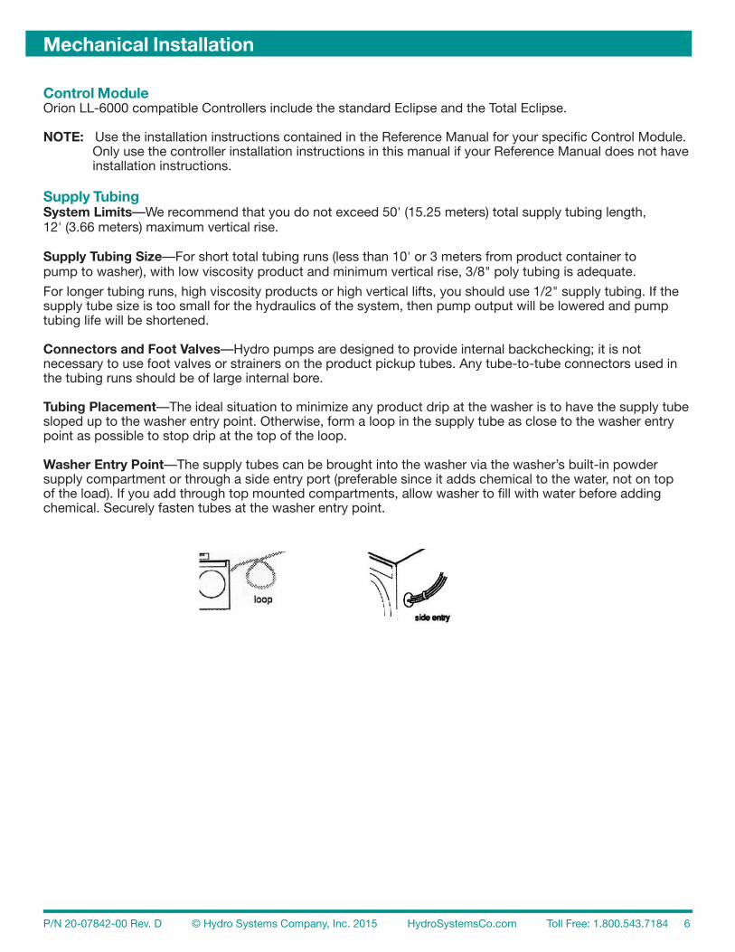
Tubing Placement—The ideal situation to minimize any product drip at the washer is to have the supply tube sloped up to the washer entry point. Otherwise, form a loop in the supply tube as close to the washer entry point as possible to stop drip at the top of the loop.
Washer Entry Point—The supply tubes can be brought into the washer via the washer’s built-in powder supply compartment or through a side entry port (preferable since it adds chemical to the water, not on top of the load). If you add through top mounted compartments, allow washer to fill with water before adding chemical. Securely fasten tubes at the washer entry point.
Mechanical Installation
P/N 20-07842-00 Rev. D © Hydro Systems Company, Inc. 2015 HydroSystemsCo.com Toll Free: 1.800.543.7184 7
Electrical Installation
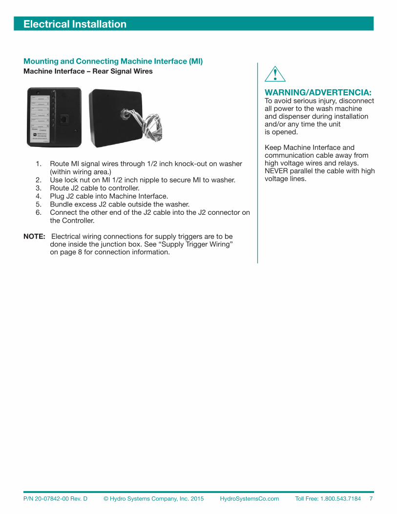
Mounting and Connecting Machine Interface (MI)Machine Interface – Rear Signal Wires
1. Route MI signal wires through 1/2 inch knock-out on washer (within wiring area.) 2. Use lock nut on MI 1/2 inch nipple to secure MI to washer. 3. Route J2 cable to controller. 4. Plug J2 cable into Machine Interface. 5. Bundle excess J2 cable outside the washer. 6. Connect the other end of the J2 cable into the J2 connector on the Controller.
NOTE: Electrical wiring connections for supply triggers are to be done inside the junction box. See “Supply Trigger Wiring” on page 8 for connection information.
!WARNING/ADVERTENCIA:To avoid serious injury, disconnect all power to the wash machine and dispenser during installation and/or any time the unit is opened.
Keep Machine Interface and communication cable away from high voltage wires and relays. NEVER parallel the cable with high voltage lines.
P/N 20-07842-00 Rev. D © Hydro Systems Company, Inc. 2015 HydroSystemsCo.com Toll Free: 1.800.543.7184 8
Compatible ControllersNOTE: Controllers that are compatible with the Orion LL-6000 include the standard Eclipse and the Total Eclipse. Use the installation instructions contained in the Reference Manual for your specific Control Module. Only use the controller installation instructions in this manual if your Reference Manual does not have installation instructions.
Supply Trigger Wiring 1. Identify the washer supply signals. Check with technical service or with the washer manufacturer if you are not sure of the connections. (See “Washer Wiring–Contacts for Manufacturers” on page 12 for a list of phone numbers.) 2. Use appropriate terminal connectors to connect the signal wires to the Machine Interface wires. Use these color codes for “Timer” and “Relay” modes:
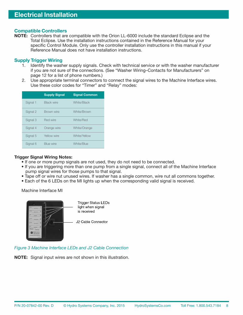
Trigger Signal Wiring Notes: • If one or more pump signals are not used, they do not need to be connected. • If you are triggering more than one pump from a single signal, connect all of the Machine Interface pump signal wires for those pumps to that signal. • Tape off or wire nut unused wires. If washer has a single common, wire nut all commons together. • Each of the 6 LEDs on the MI lights up when the corresponding valid signal is received.
Machine Interface MI
Figure 3 Machine Interface LEDs and J2 Cable Connection
NOTE: Signal input wires are not shown in this illustration.
Electrical Installation
Supply Signal Signal Common
Signal 1 Black wire White/Black
Signal 2 Brown wire White/Brown
Signal 3 Red wire White/Red
Signal 4 Orange wire White/Orange
Signal 5 Yellow wire White/Yellow
Signal 6 Blue wire White/Blue
P/N 20-07842-00 Rev. D © Hydro Systems Company, Inc. 2015 HydroSystemsCo.com Toll Free: 1.800.543.7184 9
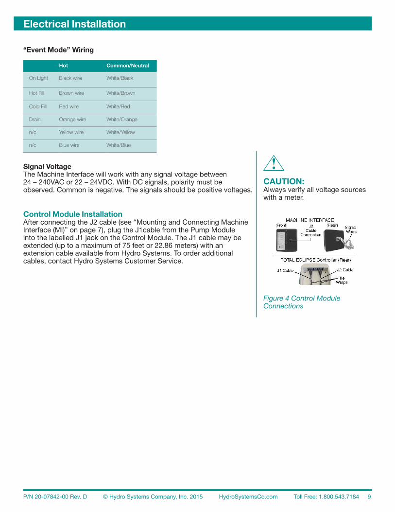
“Event Mode” Wiring
Signal VoltageThe Machine Interface will work with any signal voltage between 24 – 240VAC or 22 – 24VDC. With DC signals, polarity must be observed. Common is negative. The signals should be positive voltages.
Control Module InstallationAfter connecting the J2 cable (see “Mounting and Connecting Machine Interface (MI)” on page 7), plug the J1cable from the Pump Module into the labelled J1 jack on the Control Module. The J1 cable may be extended (up to a maximum of 75 feet or 22.86 meters) with an extension cable available from Hydro Systems. To order additional cables, contact Hydro Systems Customer Service.
Electrical Installation
Hot Common/Neutral
On Light Black wire White/Black
Hot Fill Brown wire White/Brown
Cold Fill Red wire White/Red
Drain Orange wire White/Orange
n/c Yellow wire White/Yellow
n/c Blue wire White/Blue
!CAUTION:Always verify all voltage sources with a meter.
Figure 4 Control Module Connections
P/N 20-07842-00 Rev. D © Hydro Systems Company, Inc. 2015 HydroSystemsCo.com Toll Free: 1.800.543.7184 10
Calibrate Pumps
NOTE: Refer to your Controller’s Reference Manual to determine the proper calibration method (timed or volume) for your Controller.
You must calibrate all pumps, via the Controller, using either the volume or timed methods of calibration. If you do not calibrate a pump properly, your pumped amounts could be wrong or the pump may not run. Calibrate pumps according to instructions in your controller’s manual.
MaintenancePump tubes should be replaced regularly. Products, product throughput and operating conditions determine tube life. Try to replace tubes before they fail and leak chemical into the pump housing.
Tube Replacement 1. Loosen either the knurled thumbscrews on the small pump faceplate or the five Phillips screws on the large pump faceplate. 2. Lift off faceplate and pull tubing out. 3. If tube was broken, clean out residual chemical with a damp cloth. 4. With roller assembly at a 1:00 / 7:00 orientation, place left end of tube in housing. 5. Rotate roller assembly clockwise as you push the tubing into the housing. This will aid the insertion of stiff or large tubes. 6. Lubricate tubing, if needed (“Correct Lubrication for Various Tube Types” below to see appropriate lubricant for your tube type). 7. Replace faceplate and finger tighten the thumbscrews or tool tighten the steel screws.
Tube LubricationNew tubes for the peristaltic pumps may be lubricated lightly with the appropriate lubricant. Excessive lubricant will cause premature tube wear. Use the lubrication recommended in the table below foryour tube type.
Correct Lubrication for Various Tube Types
Periodic CleaningWipe soil from housings, pump housings, etc. with a damp cloth.
Programming & Maintenance
!CAUTION:Always wear eye protection when working with strong or hazardous chemicals.
Tube Type Lubrication
Santoprene, EPDM, Viton Silicone Lube
Silicone Silicone or Vaseline-type Lube
C-Flex No Lube
P/N 20-07842-00 Rev. D © Hydro Systems Company, Inc. 2015 HydroSystemsCo.com Toll Free: 1.800.543.7184 11
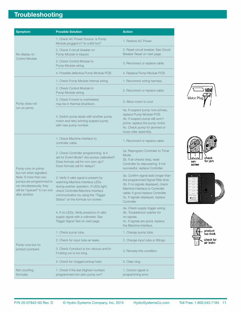
Troubleshooting
Symptom Possible Solution Action
No display on Control Module
1. Check AC Power Source. Is PumpModule plugged in? Is outlet live?
1. Restore AC Power.
2. Check if circuit breaker onPump Module is tripped.
2. Reset circuit breaker. See Circuit Breaker Reset on next page.
3. Check Control Module toPump Module wiring.
3. Reconnect or replace cable.
4. Possible defective Pump Module PCB. 4. Replace Pump Module PCB.
Pump does notrun on prime.
1. Check Pump Module internal wiring. 1. Reconnect wiring harness.
2. Check Control Module toPump Module wiring.
2. Reconnect or replace cable.
3. Check if motor is overheated,may be in thermal shutdown.
3. Allow motor to cool.
4. Switch pump leads with another pumpmotor and retry priming suspect pumpwith new pump number.
4a. If suspect pump now primes,replace Pump Module PCB.4b. If suspect pump still won’t prime, replace the pump motor.4c. Check pump for jammed or loose roller assembly.
Pump runs on prime, but not when signalled.Note: If more than two pumps are programmed torun simultaneously, they will be “queued” to run one after another.
1. Check Machine Interface tocontroller cable.
1. Reconnect or replace cable.
2. Check Controller programming. Is itset for Event Mode? Are pumps calibrated?Does formula call for non-zero qty?Does formula call for delays?
2a. Reprogram Controller to Timer Mode.2b. If all checks okay, reset Controller by depowering. If not successful, replace Controller.
3. Verify if valid signal is present bywatching Machine Interface LEDsduring washer operation. If LEDs light,check Controller/Machine Interfacecommunication by using the “TriggerStatus“ on the formula run screen.
3a. Confirm signal lasts longer than the programmed Signal Filter time.3b. If no signals displayed, check Machine Interface to Controller cable; if good replace Controller.3c. If signals displayed, replace Controller.
4. If no LEDs, Verify presence of validsupply signal with a voltmeter. SeeTrigger Signal Test on next page.
4a. Check supply trigger wiring.4b. Troubleshoot washer for no signals.4c. If signals are good, replace the Machine Interface.
Pump runs but noproduct pumped.
1. Check pump tube. 1. Change pump tube.
2. Check for input tube air leaks. 2. Change input tube or fittings.
3. Check if product is too viscous and/or if tubing run is too long.
3. Remedy this condition.
4. Check for clogged pickup tube. 4. Clear clog.
Not countingformulas.
1. Check if the last (highest number)programmed non-zero pump run?
1. Correct signal or programming error.

P/N 20-07842-00 Rev. D © Hydro Systems Company, Inc. 2015 HydroSystemsCo.com Toll Free: 1.800.543.7184 12
Circuit Breaker ResetIf the Breaker (left bottom rear of Pump Module)needs resetting, verify that all motors are okay and nopumps are jammed or the unit will shut down again.
Trigger Signal TestIf you cannot obtain indication of signals on the Machine Interface or Control Module, use a meter to verify voltages between signal wires and common connections.
Repair ProceduresIf you need to return items for repair, please obtain a returned product authorization number from Hydro Systems (RPA#) and a note describing the symptoms encountered.
Washer Wiring–Contacts for ManufacturersIf you are unfamiliar with the washer to which you are wiring, either contact the washer manufactureror Hydro Systems for technical assistance. The following list of manufacturers and contact numbersis supplied for your reference. This list, current at the time of publication, may become outdatedif manufacturers cease doing business or change their phone numbers.
When contacting a washer manufacturer, have the model and serial numbers of the machine handy, asongoing washer upgrades may change the wire numbers from time to time.
The ORION Machine Interface can accept any single phase voltage signal from 18 VAC - 240 VAC or DC.
Troubleshooting
Washer Manufacturers/Wash Machine Names Location Contact
Alliance Laundry Systems (Huebsch) Ripon, WI 800.553.5120
Alliance Laundry Systems (Speed Queen) Ripon, WI 800.345.5649
Alliance Laundry Systems (UniWash, UniMac, Ajax) Ripon, WI 800.587.5458 or 920.748.3121
Brim Laundry Machinery Co. Dallas, TX 800.527.5886 or 214.630.4517
Dexter Co. Fairfield, IA 641.472.5131
Edro Corp. (DynaWash) East Berlin, CT 860.828.0311
Ellis Corp. Itasca, IL 800.453.9222
G A Braun Inc. Syracuse, NY 800.432.7286 or 315.475.3123
Girbau Co. Oshkosh, WI 800.256.1073 or 920.231.8222
IPSO, USA Panama City, FL 800-872-4776
Jensen (Senking, D’Hooge, L-TRON) Fort Mills, SC 803.548.3653
Kannegiesser USA(Favorit, Futura, PowerTrans, RotaFlex) Grand Prairie, TX 800.344.0403
Pellerin Milnor Kenner, LA 800.469.8780 or 504.467.9591
Wascomat, Inc. (Wascomat, Wascator) Inwood, NY 800.645.2204 or 516.371.4400
Washex / Lavatec Wichita Falls, TX 800.433.0933 or 940-855-3990

P/N 20-07842-00 Rev. D © Hydro Systems Company, Inc. 2015 HydroSystemsCo.com Toll Free: 1.800.543.7184 13
Specifications & Limited Warranty
Specifications
LL-6000 Pump Module (6 pump) Dimensions
Size 33" W x 8" H x 5.5" D (83.8 cm W x 20.3 cm H x 14 cm D) (cabinet length varies by type of pump)
Weight 68 lbs. (30.9 kg.)
General
Temperature 120° F. (49° C.) Maximum
Power 115 VAC (+/- 10%), 60 Hz 240 VAC, 50 Hz optional
Circuit Breaker 6 amps
Signal Inputs From Control Module, up to 75 ft. (22.9 m)
Total Amperage draw during operation < 6 amps
Pump Flow Rate 46 oz. (1.2 liters)/minute capacity, Peristaltic type 30 oz. (887 mls)/minute capacity, Peristaltic type w/high-torque motor 18 oz. (532 mls)/minute capacity, modified Peristaltic type
Machine Interface Dimensions
Size 5.0" W x 5.25" H x 1.5" D (12.7 cm W x 13.3 cm H x 3.8 cm D)
Weight 10 oz. (.28 kg.)
NOTE: Specifications subject to change without notice.
General Requirements for ALL Controllers
Power Supplied by Pump Module
Signal Inputs via Machine Interface, 6 channels, 18 to 250 VAC
Temperature 120° F. (49° C.) Maximum
Limited WarrantySELLER warrants solely to BUYER the Products will be free from defects in material and workmanship under normal use and service for a period of one year from the date of completion of manufacture. This limited warranty does not apply to (a) hoses; (b) and products that have a normal life shorter than one year; or (c) failure in performance or damage caused by chemicals, abrasive materials, corrosion, lightning, improper voltage supply, physical abuse, mishandling or misapplication. In the event the Products are altered or repaired by BUYER without SELLER’S prior written approval, all warranties will be void.
NO OTHER WARRANTY, ORAL, EXPRESS OR IMPLIED, INCLUDING ANY WARRANTY OF MERCHANTABILITY OR FITNESS FOR ANY PARTICULAR PURPOSE, IS MADE FOR THESE PRODUCTS, AND ALL OTHER WARRANTIES ARE HEREBY EXPRESSLY EXCLUDED.
SELLER’S sole obligation under this warranty will be, at SELLER’S option, to repair or replace F. O. B. SELLER’S facility in Cincinnati, Ohio any Products found to be other than as warranted.
Limitation of LiabilitySELLERS WARRANTY OBLIGATIONS AND BUYERS REMEDIES ARE SOLELY AND EXCLUSIVELY AS STATED HEREIN. SELLER SHALL HAVE NO OTHER LIABILITY, DIRECT OR INDIRECT, OF ANY KIND INCLUDING LIABILITY FOR SPECIAL, INCIDENTAL, OR CONSEQUENTIAL DAMAGES OR FOR ANY OTHER CLAIMS FOR DAMAGE OR LOSS RESULTING FROM ANY CAUSE WHATSOEVER, WHETHER BASED ON NEGLIGENCE, STRICT LIABILITY, BREACH OF CONTRACT OR BREACH OF WARRANTY.