Oriol Domínguez Martínez - Advanced Masters in ... · Oriol Domínguez Martínez Preservation and...
103
Portugal I 2015 Oriol Domínguez Martínez Preservation and repair of rammed earth constructions.
Transcript of Oriol Domínguez Martínez - Advanced Masters in ... · Oriol Domínguez Martínez Preservation and...

Portugal I 2015
Oriol Domínguez Martínez
Preservation and repair of rammed earth constructions.

Preservation and repair of rammed earth constructions
DECLARATION
Name: Oriol Domínguez Martínez
Email: [email protected]
Title of the
Msc Dissertation:
Preservation and repair of rammed earth constructions
Supervisor(s): Rui André Martins da Silva, Daniel Vitorino de Castro Oliveira
Year: 2015
I hereby declare that all information in this document has been obtained and presented in accordance
with academic rules and ethical conduct. I also declare that, as required by these rules and conduct, I
have fully cited and referenced all material and results that are not original to this work.
I hereby declare that the MSc Consortium responsible for the Advanced Masters in Structural Analysis
of Monuments and Historical Constructions is allowed to store and make available electronically the
present MSc Dissertation.
University: Universidade do Minho
Date: July 14, 2015
Signature:
ADVANCED MASTERS IN STRUCTURAL ANALYSIS OF MONUMENTS AND HISTORICAL CONSTRUCTIONS i

Preservation and repair of rammed earth constructions
ii ADVANCED MASTERS IN STRUCTURAL ANALYSIS OF MONUMENTS AND HISTORICAL CONSTRUCTIONS

Preservation and repair of rammed earth constructions
ACKNOWLEDGEMENTS
First of all, I would like to offer my special thanks to my supervisor Daniel Oliveira and especially to Rui
Silva for their patience and support during the whole dissertation process. I am particularly grateful to
Eduardo Pereira, Edgar Soares, Luís Ramos, and all the laboratory technicians of the Structural
Laboratory of the University of Minho for their support with the tests and friendship. They all made this
work possible.
My special thanks are extended to all people involved in the SAHC Masters in Guimarães, where it was
a pleasure to study, as well as to my colleagues and friends from Padova, who discovered me a great
city and a great country.
I wish to acknowledge the financial support provided by the SAHC Consortium, and the funding provided
for this research by the Portuguese Science and Technology Foundation through the project FCOMP-
01- 0124-FEDER-028864 (FCT-PTDC/ECM-EST/2396/2012).
Finally, I wish to thank to Emilio and Ángela for encouraging me to participate in this course, because I
know that something beautiful will come out from the time we were here.
And of course to my family for their unconditional support and patience all over these years.
ADVANCED MASTERS IN STRUCTURAL ANALYSIS OF MONUMENTS AND HISTORICAL CONSTRUCTIONS iii

Preservation and repair of rammed earth constructions
iv ADVANCED MASTERS IN STRUCTURAL ANALYSIS OF MONUMENTS AND HISTORICAL CONSTRUCTIONS

Preservation and repair of rammed earth constructions
ABSTRACT
Existing earthen architectural building is often affected by degradation, mainly due to the fragility of the
construction material itself together with the lack of maintenance as a result of economic and social
changes. The main threats to this heritage have been already identified and have been widely
discussed, but the limited specific knowledge on this architecture, particularly in the field of structural
analysis, does not always allow an appropriate intervention.
The present dissertation aims at contributing to the understanding on the structural behaviour of rammed
earth architectural heritage, as well as to the developing of a feasible technique to repair structural
cracks caused by earthquakes and weathering. To this aim, the specific nature of the material will be
pointed out, and the most relevant aspects within the structural assessment of rammed earth buildings
will be presented and discussed. The suitability of the grout injection as a repair/strengthening solution
for rammed earth will be assessed within an extensive experimental programme performed in the
Structural Laboratory of the University of Minho.
ADVANCED MASTERS IN STRUCTURAL ANALYSIS OF MONUMENTS AND HISTORICAL CONSTRUCTIONS v

Preservation and repair of rammed earth constructions
vi ADVANCED MASTERS IN STRUCTURAL ANALYSIS OF MONUMENTS AND HISTORICAL CONSTRUCTIONS

Preservation and repair of rammed earth constructions
RESUMO
A arquitetura de terra é frequentemente afetada por fenómenos de deterioração, devido principalmente
à vulnerabilidade do próprio material de construção em conjunto com a falta de manutenção associada
a mudanças da situação económica e social. As principais ameaças a tipo de património foram já
identificadas e discutidas intensivamente, mas o conhecimento limitado sobre este tipo de Arquitetura,
em particular na área d comportamento estrutural, não permite a utilização de soluções de intervenção
adequadas.
Esta dissertação tem como objetivo contribuir para a compreensão do comportamento estrutural do
património arquitetónico de taipa, bem como para o desenvolvimento de técnicas para a reparação de
fendas estruturais causadas por sismos e pelo próprio envelhecimento. Para conseguir-se este objetivo,
a natureza específica do material será focada e os principais aspetos relacionados com a avaliação
estrutural dos edifícios de taipa será apresentada e discutida. A adequabilidade da injeção de caldas
com solução de reparação/reforço para construção em taipa será avaliada por meio de um extenso
programa experimental a realizar-se no Laboratório de Estruturas da Universidade do Minho.
ADVANCED MASTERS IN STRUCTURAL ANALYSIS OF MONUMENTS AND HISTORICAL CONSTRUCTIONS vii

Preservation and repair of rammed earth constructions
viii ADVANCED MASTERS IN STRUCTURAL ANALYSIS OF MONUMENTS AND HISTORICAL CONSTRUCTIONS

Preservation and repair of rammed earth constructions
RESUMEN
El patrimonio construido con tierra es un patrimonio en riesgo. La fragilidad del material unido a la falta
mantenimiento son sus principales amenazas. La problemática ya ha sido profusamente estudiada e
identificada, y son notables los esfuerzos realizados para su recuperación. No obstante, las medidas
adoptadas no siempre son las adecuadas debido a la falta de conocimiento sobre el material,
especialmente en el campo del análisis estructural.
El presente estudio tiene el objetivo de contribuir a la comprensión del comportamiento estructural del
patrimonio construido con tapia, así como el desarrollo de técnicas de intervención factibles que
permitan la efectiva reparación de grietas. Para acometer dichos objetivos, las propiedades específicas
del material serán expuestas y analizadas, así como los aspectos más relevantes en el análisis
estructural de edificios de tapia. Del mismo modo, se evaluará la inyección de morteros en muros de
tapia gracias mediante ensayos en el laboratorio de estructuras de la Universidade do Minho.
ADVANCED MASTERS IN STRUCTURAL ANALYSIS OF MONUMENTS AND HISTORICAL CONSTRUCTIONS ix

Preservation and repair of rammed earth constructions
x ADVANCED MASTERS IN STRUCTURAL ANALYSIS OF MONUMENTS AND HISTORICAL CONSTRUCTIONS

Preservation and repair of rammed earth constructions
TABLE OF CONTENTS
1. INTRODUCTION ............................................................................................................................. 1
1.1 Motivations .............................................................................................................................. 1
1.2 Description of the problem ...................................................................................................... 1
1.3 Objectives ................................................................................................................................ 2
2. LITERATURE REVIEW ................................................................................................................... 3
2.1 Introduction .............................................................................................................................. 3
2.2 The raw material: nature and properties of soils ..................................................................... 4
2.2.1 Clay minerals as the binding agent ................................................................................. 6
2.3 Earth as building material ........................................................................................................ 8
2.3.1 General overview of earth construction techniques ........................................................ 9
2.3.2 Rammed earth construction technique .......................................................................... 10
2.3.3 Mechanical behaviour of rammed earth structures ....................................................... 12
2.4 Damage and vulnerability of rammed earth structures ......................................................... 13
2.4.1 Vulnerability against water ............................................................................................ 14
2.4.2 Biological actions ........................................................................................................... 16
2.4.3 Mechanical damages ..................................................................................................... 16
2.4.4 Seismic vulnerability ...................................................................................................... 17
2.5 Conclusions ........................................................................................................................... 20
3. SURVEY ON RAMMED EARTH HERITAGE ............................................................................... 21
3.1 Introduction ............................................................................................................................ 21
3.2 Traditional architecture in Southern Portugal ........................................................................ 21
3.3 On-site investigation .............................................................................................................. 21
3.4 Structural survey .................................................................................................................... 23
3.4.1 Walls .............................................................................................................................. 23
3.4.2 Roofs ............................................................................................................................. 25
3.4.3 Plasters .......................................................................................................................... 25
3.5 Damage survey ..................................................................................................................... 25
3.5.1 Mechanical damage ...................................................................................................... 26
3.5.2 Physical damage ........................................................................................................... 26
3.6 Empirical seismic improvements ........................................................................................... 26
3.7 Conclusions ........................................................................................................................... 27
4. UNSTABILISED RAMMED EARTH ASSESSMENT .................................................................... 28
4.1 Introduction ............................................................................................................................ 28
4.2 Soil identification .................................................................................................................... 28
4.2.1 Texture and cohesion .................................................................................................... 29
4.2.2 Plasticity ........................................................................................................................ 32
ADVANCED MASTERS IN STRUCTURAL ANALYSIS OF MONUMENTS AND HISTORICAL CONSTRUCTIONS xi

Preservation and repair of rammed earth constructions
4.2.3 Compaction .................................................................................................................... 34
4.2.4 Durability ........................................................................................................................ 36
4.3 Mechanical properties ............................................................................................................ 37
4.3.1 Uniaxial compression test .............................................................................................. 37
4.3.2 Flexural bending strength .............................................................................................. 40
4.3.3 Diagonal compression tests ........................................................................................... 40
4.4 Conclusions ........................................................................................................................... 47
5. REPAIR OF RAMMED EARTH BY MEANS OF GROUT INJECTION ......................................... 49
5.1 Introduction ............................................................................................................................ 49
5.2 Grout injection of cracks ........................................................................................................ 49
5.2.1 Grout properties ............................................................................................................. 49
5.3 Grout injection of rammed earth specimens .......................................................................... 51
5.3.1 Characterization and preparation of grouts ................................................................... 52
5.3.2 Injection of the rammed earth wallets ............................................................................ 54
5.3.3 Diagonal compression tests of rammed earth wallets ................................................... 56
5.4 Sonic tests ............................................................................................................................. 63
5.4.1 Fundamentals of sonic test ............................................................................................ 64
5.4.2 Sonic testing procedure ................................................................................................. 66
5.4.3 Direct sonic tests ........................................................................................................... 67
5.4.4 Indirect sonic tests ......................................................................................................... 69
5.5 Conclusions ........................................................................................................................... 72
6. Conclusions and future work ......................................................................................................... 75
6.1 Main conclusions ................................................................................................................... 75
6.2 Future research ..................................................................................................................... 76
REFERENCES ...................................................................................................................................... 77
ANNEXES .............................................................................................................................................. 81
A. RESULTS OF THE DIAGONAL COMPRESSIVE TESTS ............................................................ 81
B. RESULTS OF THE SONIC TESTS ............................................................................................... 82
xii ADVANCED MASTERS IN STRUCTURAL ANALYSIS OF MONUMENTS AND HISTORICAL CONSTRUCTIONS

Preservation and repair of rammed earth constructions
LIST OF FIGURES
Figure 2.1 – PSD of soils: [1] with high clay content; [2] with high sand content (Minke, 2000). ............ 4
Figure 2.2 – PSD curves for different earth construction techniques (Jaquin & Augarde, 2012) ........... 5
Figure 2.3 – Simple model of an unsaturated soil (Jaquin & Augarde, 2012) ........................................ 5
Figure 2.4 – Structural units of clays: [1] aluminium sheet; [2] Silica sheet (Reddi, et al., 2012). .......... 6
Figure 2.5 – Decrease in compressive strength with an increase in the water content of unstabilised rammed earth samples, 9% clay content (Morel, et al., 2012). ............................................................... 7
Figure 2.6 – Structure of clay minerals: [1] kaolinite; [2] Illite; [3] montmorillonite (Minke, 2000). .......... 8
Figure 2.7 – External view of the ksar Ouled Yousseff, in the Drâa Valley (Terrachidia Association). .. 9
Figure 2.8 – Earth construction techniques: [1] construction of a rammed earth wall, Southern Morocco (Terrachidia Association); [2] adobe structure in Puna region, Northern Argentina. ............................ 10
Figure 2.9 – Rammed earth structures: [1] tapia in Toledo, Spain (Alejandro García Hermida); [2] pisé in Toulouse, France (Anger & Fontane, 2009). ..................................................................................... 11
Figure 2.10 – Moisture content and dry density for different techniques (Jaquin & Augarde, 2012). ... 13
Figure 2.11 – The citadel of Bam (Iran) before and after 2003 earthquake (Langenbach, 2005). ....... 14
Figure 2.12 – Rammed earth building affected by long term weathering, in M’Hamid El Ghezlane, Southern Morocco (Terrachidia Association). ....................................................................................... 15
Figure 2.13 – Termite damage in an adobe structure (Langenbach, 2005). ........................................ 16
Figure 2.14 – Failure of structural elements in earthen buildings (Jaquin & Augarde, 2012). .............. 17
Figure 2.15 – Typical earthquake-damage pattern in rammed earth buildings: [1] vertical cracking; .. 18
Figure 3.1 – Map of southern Portugal with the location of the studied buildings. ................................ 23
Figure 3.2 – [1] Case study #10. Rural house in Serpa; [2] texture of the rammed earth. Case study #13. Rural house in Vales Mortos. ........................................................................................................ 24
Figure 3.3 – Roof collapse. Case study #23. Stockyard in Pedrogão................................................... 25
Figure 3.4 – Damage on rammed earth structures: [1] overturning of façades. Case study #19. Rural house in Montes Velhos; [2] weathering. Case study #21. Urban house in Cuba. ............................... 26
Figure 3.5 – Seismic strengthening: [1] horizontal stones embedded in the wall. Case study #1. Rural house in Cercal; [2] anchor plate. Case study #19. Rural house in Montes Velhos. ............................ 27
Figure 4.1 – Soil SM after dry sieving. .................................................................................................. 29
Figure 4.2 – Optimal PSD curve for rammed earth recommended by the German Code (Röhlen & Ziegert, 2014). ....................................................................................................................................... 30
Figure 4.3 – PSD curve of the soil SM. ................................................................................................. 31
Figure 4.4 – Determination of the Liquid Limit of Soil SM with the Casagrande shell method. ............ 33
ADVANCED MASTERS IN STRUCTURAL ANALYSIS OF MONUMENTS AND HISTORICAL CONSTRUCTIONS xiii

Preservation and repair of rammed earth constructions
Figure 4.5 – Consistency of soils S5, S6 and SM compared with recommended ranges of values. .... 34
Figure 4.6 – Compaction curve of soils S5 and S6 (Silva, 2013). ......................................................... 36
Figure 4.7 – Results of abrasion test conducted with laboratory test apparatus (Minke, 2011). .......... 36
Figure 4.8 – Set-up of the uniaxial compressive test. ........................................................................... 37
Figure 4.9 – Stress-strain curves of the six cylindrical specimens, CURE_1 to CURE_6. ................... 38
Figure 4.10 – Failure mode of the specimen CURE_6 with the formation of a main diagonal crack. ... 39
Figure 4.11 – Test setup of the diagonal compression tests: [1] test apparatus; [2] placement of the LVDTs. ................................................................................................................................................... 41
Figure 4.12 – Stress-strain curves of the six wallets before injection, WURE_1 to WURE_6. ............. 43
Figure 4.13 – Stress-strain curve of the wallet WURE_2. ..................................................................... 43
Figure 4.14 – Resultant maximum principal strains from the DIC analysis of WURE_2. ...................... 44
Figure 4.15 – Results from the DIC analysis of WURE_4. .................................................................... 44
Figure 4.16 – Resultant maximum principal strains from the DIC analysis of WURE_4. ...................... 45
Figure 4.17 – Failure pattern of the tested wallets: [1] WURE_1; [2] WURE_2; [3] WURE_3; [4] WURE_4; [5] WURE_5; [6] WURE_6. ................................................................................................... 47
Figure 5.1 – Marsh cone used in the flow time tests carried out at UMinho (dimensions in mm). ........ 50
Figure 5.2 – Sand column to test the penetrability of a grout. ............................................................... 51
Figure 5.3 – Preparation of the grout G3: [1] components of the grout before being mixed; [2] mixture with an electrical mixer. ......................................................................................................................... 52
Figure 5.4 – Characterization of grouts: [1] measurement of the flow time of the grout G3 through a Marsh cone; [2] moulding process for the preparation of the specimens. ............................................. 53
Figure 5.5 – Testing of the grout specimens: [1] under bending; [2] under compression. .................... 54
Figure 5.6 – Injection of the rammed earth wallets: [1] sealing of the cracks and placement of tubes; [2] injection of the grout with a syringe. ................................................................................................. 55
Figure 5.7 – Stress-strain curves before and after injection: [1] WUREi_1; [2] WUREi_3 .................... 57
Figure 5.8 – Results from the DIC analysis of WUREi_2. ..................................................................... 58
Figure 5.9 – Resultant maximum principal strains from the DIC analysis of WUREi_2. ....................... 59
Figure 5.10 – Results from the DIC analysis of WUREi_4. ................................................................... 59
Figure 5.11 – Resultant maximum principal strains from the DIC analysis of WUREi_4. ..................... 60
Figure 5.12 – Failure pattern of the tested wallets: [1] WUREi_1; [2] WUREi_2; [3] WUREi_3; [4] WUREi_4; [5] WUREi_5; [6] WUREi_6 ................................................................................................. 61
Figure 5.13 – Adhesion between grout and rammed earth: [1] WUREi_3; [2] WUREi_6; .................... 62
Figure 5.14 – Voids due to a deficient penetrability of the grout G3 in WUREi_3. ............................... 63
xiv ADVANCED MASTERS IN STRUCTURAL ANALYSIS OF MONUMENTS AND HISTORICAL CONSTRUCTIONS

Preservation and repair of rammed earth constructions
Figure 5.15 – Transmission of waves and relative velocities [1], and recorded signal [2] (Mendes, 2009) ..................................................................................................................................................... 64
Figure 5.16 – [1] Set of instruments used in sonic tests; [2] direct sonic test. Overlapping of the signal of the hammer and of the accelerometer. ............................................................................................. 65
Figure 5.18 – Testing grid for the indirect measurements in both sides of the panel. .......................... 66
Figure 5.19 – Indirect sonic test. Overlapping of the signal of the hammer and of the accelerometer. 67
Figure 5.20 – Indirect sonic test. Overlapping of the signal of the hammer and of the accelerometer. 67
Figure 5.21 – Average velocities of the direct sonic tests in all specimens. ......................................... 68
Figure 5.22 – Average results of the direct sonic tests. [a] WURE_1; [b] WURE_2. ............................ 69
Figure 5.23 – Average results of the horizontal measurements with indirect sonic tests. .................... 70
Figure 5.24 – Average results of the vertical measurements with indirect sonic tests. ........................ 70
Figure 5.25 – Sealing of the WUREi_5. ................................................................................................ 72
Figure 5.26 – Average results of the horizontal indirect sonic tests for WUREi_5: [1] horizontal measurements; [2] vertical measurements. .......................................................................................... 72
Figure A.1 – Stress-strain curves of the injected wallets: [1] WUREi_1; [2] WUREi_2; [3] WUREi_3; [4] WUREi_4; [5] WUREi_5; [6] WUREi_6 ................................................................................................. 81
Figure B.1 – Average results of the direct sonic tests: [1] WURE_1; [2] WURE_2; [3] WURE_3; [4] WURE_4; [5] WURE_5; [6] WURE_6 ................................................................................................... 83
Figure B.2 – Average results of the vertical indirect sonic tests: [1] WUREi_1; [2] WUREi_2; [3] WUREi_3; [4] WUREi_4; [5] WUREi_5; [6] WUREi_6 .......................................................................... 85
Figure B.3 – Average results of the horizontal indirect sonic tests: [1] WUREi_1; [2] WUREi_2; [3] WUREi_3; [4] WUREi_4; [5] WUREi_5; [6] WUREi_6 .......................................................................... 86
ADVANCED MASTERS IN STRUCTURAL ANALYSIS OF MONUMENTS AND HISTORICAL CONSTRUCTIONS xv

Preservation and repair of rammed earth constructions
LIST OF TABLES
Table 2.1 – Range of particle sizes in soils (ISO, 2013). ........................................................................ 4
Table 2.2 – Mechanical and physical properties of earth building materials (Röhlen & Ziegert, 2014). . 9
Table 3.1 – List of studied buildings. ..................................................................................................... 22
Table 4.1 – PSD of soils S5 and S6 (Silva, 2013), and soil SM compared with the German recommendations for rammed earth (Dachverband Lehm e.V., 2009). ................................................ 31
Table 4.2 – Atterberg limits of soils S5 and S6 (Silva, 2013), soil SM, and recommended values. ...... 33
Table 4.3 – Compaction properties of soils S5 and S6 (Silva, 2013), and soil SM ............................... 35
Table 4.4 – Results of the cylinders tested under compression. ........................................................... 38
Table 4.5 – Results of the wallets tested under diagonal compression. ............................................... 42
Table 5.1 – Composition of the mud grouts G1 and G2 (Silva, 2013). ................................................. 52
Table 5.2 – Composition of the grout G4 used to repair the rammed earth wallets. ............................. 53
Table 5.3 – Properties of the grouts G1, G2 (Silva, 2013), G3 and G4. ............................................... 53
Table 5.4 – Conditions of the injection of the wallets. ........................................................................... 55
Table 5.5 – Results of the wallets repaired with the grout G3. .............................................................. 56
Table 5.6 – Results of the wallets repaired with the grout G4. .............................................................. 56
Table 5.7 – Values of the water content and density of the injected wallets. ........................................ 63
Table 5.8 – Results of the direct sonic tests before and after the grouting. .......................................... 68
Table 5.9 – Results of the vertical indirect sonic tests before and after the grouting. ........................... 71
Table 5.10 – Results of the horizontal indirect sonic tests before and after the grouting. .................... 71
Table B.1 – Results of the direct sonic tests in the wallets repaired with the grout G3. ....................... 82
Table B.2 – Results of the direct sonic tests in the wallets repaired with the grout G4. ....................... 82
Table B.3 – Results of the vertical indirect sonic tests in the wallets repaired with the grout G3. ........ 84
Table B.4 – Results of the vertical indirect sonic tests in the wallets repaired with the grout G4. ........ 84
Table B.5 – Results of the horizontal indirect sonic tests in the wallets repaired with the grout G3. .... 84
Table B.6 – Results of the horizontal indirect sonic tests in the wallets repaired with the grout G4. .... 84
xvi ADVANCED MASTERS IN STRUCTURAL ANALYSIS OF MONUMENTS AND HISTORICAL CONSTRUCTIONS

Preservation and repair of rammed earth constructions
1. INTRODUCTION
1.1 Motivations
It is necessary to reconsider the way we build, and traditional architecture, built with local surrounding
materials, sustainable by definition, integrated in the landscape, and with an optimum climate behaviour,
stands out as an alternative. Traditional empirical processes of knowledge transmission, from one
generation to another, have been improving this architecture for centuries, and it is the result of how the
local population learnt to inhabit their territory according to the natural resources. Sustainability, such a
trendy term nowadays, is complete and very ancient in this architecture.
There are many lessons to learn —or to re-learn— from traditional architecture to be applied in the
construction of new buildings, but it is also important to understand the importance of preserving historic
constructions. Heritage, in a wide sense of the word, cannot be related only to the architectonical,
historical and cultural relevance of the monumental buildings, because they are exceptional. The
importance of heritage also relies on the popular culture, since a wide part of the society belongs to it.
There are in Europe, of course, many examples of monuments built with earth, but they are an exception,
and most of earthen constructions are —or were—, in fact, part of the popular architecture. Earthen
materials are indeed considered as poor in western cultures, because they always belonged to
poorness. This is the reason why traditional architecture, and especially earth as construction material,
is still not well considered. However, this is starting to change, in part due to the sustainability of the
material, but also because of the increasing need to respect architecture as a part of the historical
identity of the society. And since society wants to move towards sustainability, it is necessary to
reconsider not only the way we build, but also the way we manage our heritage.
The present dissertation is a result of this renewed interest, particularly of the University of Minho, which
in recent years is carrying out research in the Portuguese traditional architecture. The interest of
educational institutions is extremely important not only to guarantee a scientific approach to this topic,
but mainly as a first step to increase the awareness about this heritage within the society.
1.2 Description of the problem
Many earthen buildings are in such a vulnerable situation that makes the permanent loss of this heritage
only a matter of time. The lack of proper maintenance caused by economic and social changes, together
with the fragility of the material itself, are the main threats of this heritage. However, even in those cases
in which comprehensive interventions are possible, there is a lack of reliable techniques for earthen
structures.
Therefore, it is necessary to find new intervention techniques for earthen buildings, or to adapt those
already existing —and proved— to the specific characteristics of the material. The use of ties, geotextile
meshes or the use of centre-core rods have interesting possibilities when applied to earthen materials,
ADVANCED MASTERS IN STRUCTURAL ANALYSIS OF MONUMENTS AND HISTORICAL CONSTRUCTIONS 1

Preservation and repair of rammed earth constructions
and they are being tested for adobe structures within the research programs of several institutions such
as the Catholic University of Peru. However, in the case of rammed earth structures, there is still an
important lack of research that demands the development of new techniques and/or the adaptation of
existing ones.
This is the context in which the present dissertation aims at contributing to the development of grouting
in rammed earth walls. This technique has been extensively used in ancient masonry and its
effectiveness has been widely proved. However, the particular characteristics of the materials needs
also of specific requirements that must be properly assessed.
1.3 Objectives
This work aims at contributing to the understanding on the structural behaviour of rammed earth
architectural heritage, as well as to the development of grouting as a feasible technique to repair
structural cracks caused by earthquakes and weathering.
To this aim, the second Chapter briefly presents a critical review of literature about the main topics
related to rammed earth. These are mainly related to the description of the general properties of the
unmodified soils, especially those of clays, and to point out the general behaviour of rammed earth
structures, as well as its vulnerable aspects.
The third Chapter includes a brief on-site investigation campaign that has been carried out in Alentejo
and Algarve, focused on the specific constructive elements of the traditional architecture built with
rammed earth in these regions, especially with respect to their conservation condition and seismic
culture.
Within the fourth Chapter, the methodology for the assessment of the suitability of soils for rammed
earth is presented and discussed. In the same way, six rammed earth cylinders and wallets are tested
under uniaxial compression and diagonal compression in order to evaluate the mechanical performance
of the material before the injection of grouts.
The fifth Chapter is focused on the requirements of the formulation of grouts and of the injection process.
In this Chapter, the mechanical behaviour of the injected rammed earth wallets will be assessed by
means of the diagonal compressive test, and the results will be compared with those previously
obtained. The quality of the injection will also be assessed by means of non-destructive testing of the
wallets before and after grouting.
Finally, the sixth Chapter presents the final conclusions and the suggested future lines of research.
The procedures followed for the assessment of soils, the formulation of the grouts, as well as the tested
specimens before and after being injected are based on the study carried out in Silva (2013), in which
the present dissertation is based.
2 ADVANCED MASTERS IN STRUCTURAL ANALYSIS OF MONUMENTS AND HISTORICAL CONSTRUCTIONS

Preservation and repair of rammed earth constructions
2. LITERATURE REVIEW
2.1 Introduction
Nowadays, in the so called developed societies, tradition tends to disappear. Only a few decades of the
last 20th Century were enough to globally change our paradigms and social imaginary towards
modernity, which meant an absolute break-point with traditions. Architecture, as an essential point of
any culture, necessarily changed in the same way.
The Sixties were years of revision and rethinking, and the most critics began to claim that modernism,
the so called International style, was making us living in the same reinforced concrete boxes all across
this developed world. The implosion of the Pruitt-Igoe housing complex in 1972 led new architecture to
post-modernism (Jencks, 1984), to which Aldo Rossi gave an initial theoretical background to the
movement in Europe, aiming at going back and recovering the essence of traditions in architecture and
urbanism (Rossi, 1966). However, his work demonstrate that practice did not fit with theory, and post-
modernism led architecture, from its very beginning, to kitsch. Architecture is not only construction, as
well as traditional architecture is not only a façade. We simply cannot build cities as before.
Still in Italy, in the field of restoration, Cesare Brandi underlined the importance of the intangible values
of heritage (Brandi, 1963). Restoration is not only a technical problem, but mainly a cultural issue
(Torsello, 2005). Therefore, we need to understand the context, namely the landscape, before
intervening any building. This means construction, nature and culture, and the scope of the intervention
must be widen from architecture to archaeology and history with a scientific approach, as declared in
the Venice Charter (ICOMOS, 1964).
However, most of this knowledge has been already lost, and it is necessary to recover it with a global
scope, cross relating different fields of knowledge. In this regard, masonry have been extensively studied
—and still is—, and it is possible to state the existence of consensus regarding related techniques,
properties, local variations, etc. A wide approach is even more necessary when considering earthen
architecture’s great variety, but in despite of this, this architecture withstands lack of knowledge and
understanding (Serra, 2006).
With this objective, and within the described background, many efforts have been done since the First
International Conference on the Study and Conservation of Earthen Heritage was organized by the
International Council on Monuments and Sites (ICOMOS, 1972). This series of conferences are
intended to exchange experiences between a wide range of professionals, and the proceedings of the
eleven conferences that so far have been held represent a state of the art on the field. Nevertheless it
is important to stress that conservation of earthen architectural heritage —as a field of study and a
professional practice— is still very recent, and deeper and cross related multidisciplinary researches
are necessary in order to avoid incorrect approaches and/or considerations.
ADVANCED MASTERS IN STRUCTURAL ANALYSIS OF MONUMENTS AND HISTORICAL CONSTRUCTIONS 3

Preservation and repair of rammed earth constructions
2.2 The raw material: nature and properties of soils
Soil results from the alteration of the parent rock, which occurs through mechanical, physical, chemical
and biological actions. The resulting material undergoes further transformations as it is continuously
transported, deposited, compressed, and/or chemically modified (Houben & Guillaud, 1989). The
mechanical properties of unstabilised soils —soils without additives or corrections— essentially depend
upon the grain size of their constituents rather than to their chemical composition or the type of alteration
(Torraca, 2009). For this reason, soils are mainly defined by the distribution of their particles, which are
classified according to their size (Table 2.1).
Table 2.1 – Range of particle sizes in soils (ISO, 2013).
Particle Diameter Range
[mm]
Fine fraction Clay ≤ 0.002
Silt 0.002 – 0.063
Coarse fraction Sand 0.063 – 2
Gravel 2 – 10
Very coarse fraction Cobbles 10 – 200
Boulders > 200
The Particle Size Distribution —PSD— is commonly represented on a graph where the vertical axis
represents weight by percentage of the total of each grain size, which in turn is plotted on the horizontal
axis using a logarithmic scale. The curve is plotted cumulatively, with each grain size including all the
fine components (Figure 2.1).
[1] [2]
Figure 2.1 – PSD of soils: [1] with high clay content; [2] with high sand content (Minke, 2000).
The classification of soils may vary depending on the country and the standard being considered, but
fractions remain the same. In any case, earthen materials are referred to mineral soils with particular
PSD depending on the technique (Figure 2.2), and consist of a binding agent —the clay minerals— and
aggregates —the coarser fractions—, which in earth construction are generally sieved to less than 10
mm, (Jaquin, 2008) even if in historical rammed earth structures it is usual to find very coarse fractions. 4 ADVANCED MASTERS IN STRUCTURAL ANALYSIS OF MONUMENTS AND HISTORICAL CONSTRUCTIONS

Preservation and repair of rammed earth constructions
Figure 2.2 – PSD curves for different earth construction techniques (Jaquin & Augarde, 2012)
Therefore, clays are a fundamental fraction in soils, and they are almost always present in different
forms and with a wide variety of properties (Houben & Guillaud, 1989). Soils with high quantities of clays
are known as rich mixtures or rich clayey soils, and have high binding characteristics. On the other hand,
those that are not very cohesive are known as lean mixtures or lean clayey soils.
It is important to note that fine fractions —both clay and silt— are composed of cohesive and non-
cohesive minerals, which often can form 10%–20% of the fine particles (Velde, 2008). Therefore, the
binding strength of an earth mixture may vary considerably depending on the type of clay minerals, e.g.
kaolinite or illite, and the proportion of non-cohesive minerals, e.g. quartz, feldspars, and metal oxides
(Röhlen & Ziegert, 2014). Fine non-binding fractions contribute to soil stability by increasing its internal
friction, which is the key mechanical concept in soil strength. Nevertheless the main contributors to
strength are coarse fractions, with higher friction between particles. They constitute the skeleton in the
mixture, and their low sorption capacity limits swell and shrinkage (Houben & Guillaud, 1989).
Unstabilised soil strength depends on the binding forces of clays and on friction forces between coarse
particles, but also on the free water in the voids between them, which acts as a bridge (Figure 2.3).
These voids can be filled with air and water —unsaturated soil—, or completely with water —saturated
soil. In the majority of geotechnical projects, soil is assumed to be saturated, since the numerical and
analytical models are simpler, but it is clear that earthen materials are never neither completely dry nor
saturated (Jaquin, 2008).
Figure 2.3 – Simple model of an unsaturated soil (Jaquin & Augarde, 2012)
ADVANCED MASTERS IN STRUCTURAL ANALYSIS OF MONUMENTS AND HISTORICAL CONSTRUCTIONS 5

Preservation and repair of rammed earth constructions
Therefore, it is necessary to precisely evaluate the contribution of water and air in the model of the
earthen material and account it in the development of design rules for earthen construction.
Nevertheless there is a lack of consensus about the constitutive modelling to be considered, which is
an active area of research (Augarde, 2012). In qualitative terms, however, basic mechanical properties
of earthen materials are characterized by low compressive and shear strength, and almost zero tensile
strength (Miccoli, et al., 2014).
In short, properties of unstabilised earthen materials are determined by the properties of the binding
agent and of the aggregates, as well as their relative proportions, i.e. texture, and the amount of water.
Therefore, not all soils are adequate for earthen construction, and it is not common to find natural earth
mixtures with ideal distribution of clays and aggregates. However, it is not possible to state that a soil is
unsuitable without testing its performance of the final earthen material (Röhlen & Ziegert, 2014).
2.2.1 Clay minerals as the binding agent
Clay minerals belong to the phyllosilicates group of minerals and consist in a layer structure forming
crystals, with sizes and chemical composition that depend on the type of parent rock and degree of
weathering. Each layer constitutes a unit cell, which is a two or three-layer structure formed by alumina
octahedrons —less commonly magnesium or iron— and silica tetrahedrons (Figure 2.4).
[1]
[2]
Figure 2.4 – Structural units of clays: [1] aluminium sheet; [2] Silica sheet (Reddi, et al., 2012).
The aggregation of these basic units forming crystals depends on the type of structure. In the case of
the two-layered unit cells, hydrogen bonds are formed between the oxygen atoms at the surface of the
silica layer, and the hydroxyls at the surface of the alumina layer. These bonds strongly hold successive
units, leaving a small space between them, so water is less able to penetrate (Reddi, et al., 2012).
In the case of the three-layered unit cells, bonding occurs when the aluminium cations are substituted
with iron and magnesium —with smaller positive charge—, in addition to the exchange of silicon and
aluminium atoms between layers. These structural changes are called isomorphous substitution (Reddi,
et al., 2012), and result on a negative charge of the surfaces, which is compensated by the absorption
on the unit surfaces of cations present in water, i.e. Na+ or K+.
6 ADVANCED MASTERS IN STRUCTURAL ANALYSIS OF MONUMENTS AND HISTORICAL CONSTRUCTIONS

Preservation and repair of rammed earth constructions
The weakness of this bond allows the entrance of water between unit cells —absorbed water. If clay
continues being moistened, the volume of absorbed water increases, expanding crystals. For this
reason, three-layered clay minerals are termed expansive, while two layered clays, with some
exceptions, are non-expansive (Reddi, et al., 2012).
When the water content continues increasing, the binding force of clays is reduced. In this state, crystals
easily swell but once water evaporates, coarse fractions hold their shape while clays shrinks. Cohesive
effect continues reducing with a large excess of water, leading to a reduction of the internal cohesion of
the particles of the soil and therefore, of the mechanical strength of the material (Figure 2.5) (Schroeder,
2011; Morel, et al., 2012).
Figure 2.5 – Decrease in compressive strength with an increase in the water content of unstabilised
rammed earth samples, 9% clay content (Morel, et al., 2012).
Clay particles get in suspension in dispersed state, and when the content of free water is reduced, they
get closer and electrostatic forces start acting again. The way these particles are arranged is determined
by the surface properties at the sharpen edge of the crystals. At these edges, the primary bonds of the
alumina octahedrons and silica tetrahedrons are broken, exposing aluminol (Al-OH) and silanol (Si-OH)
groups, whose charge is determined by the pH of the suspension (Silva, 2013).
Therefore, particles join edge to face —negative to positive— in acid solutions —with pH lower than the
point of zero charge of the edge—, while this process is harder to take place in alkaline solutions. Thus,
a certain quantity of clay mixed in acid solutions may be plastic —flocculation occurs—, while in very
alkaline solutions the mixture remains liquid (Anger & Fontane, 2009). This phenomena has a major
influence on the rheological behaviour of mud grouts (Silva, 2013), which will be discusses in detail
within Section 5.2.1.
In short, cohesion and flocculation of clays derive from physical phenomena —electrostatic forces—,
which are related to their mineral structure. These effects do not only depend on the content of clays,
but also on the type of mineral. There are about 15 types of clay minerals, classified in 4 main groups,
with different bases, different structure configurations, and different interstratified materials. Three main
groups define the most common clays: kaolinite, illite and montmorillonite (Reddi, et al., 2012).
ADVANCED MASTERS IN STRUCTURAL ANALYSIS OF MONUMENTS AND HISTORICAL CONSTRUCTIONS 7
Preservation and repair of rammed earth constructions
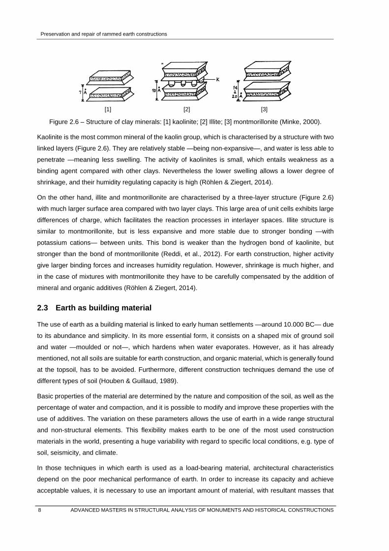
[1] [2] [3]
Figure 2.6 – Structure of clay minerals: [1] kaolinite; [2] Illite; [3] montmorillonite (Minke, 2000).
Kaolinite is the most common mineral of the kaolin group, which is characterised by a structure with two
linked layers (Figure 2.6). They are relatively stable —being non-expansive—, and water is less able to
penetrate —meaning less swelling. The activity of kaolinites is small, which entails weakness as a
binding agent compared with other clays. Nevertheless the lower swelling allows a lower degree of
shrinkage, and their humidity regulating capacity is high (Röhlen & Ziegert, 2014).
On the other hand, illite and montmorillonite are characterised by a three-layer structure (Figure 2.6)
with much larger surface area compared with two layer clays. This large area of unit cells exhibits large
differences of charge, which facilitates the reaction processes in interlayer spaces. Illite structure is
similar to montmorillonite, but is less expansive and more stable due to stronger bonding —with
potassium cations— between units. This bond is weaker than the hydrogen bond of kaolinite, but
stronger than the bond of montmorillonite (Reddi, et al., 2012). For earth construction, higher activity
give larger binding forces and increases humidity regulation. However, shrinkage is much higher, and
in the case of mixtures with montmorillonite they have to be carefully compensated by the addition of
mineral and organic additives (Röhlen & Ziegert, 2014).
2.3 Earth as building material
The use of earth as a building material is linked to early human settlements —around 10.000 BC— due
to its abundance and simplicity. In its more essential form, it consists on a shaped mix of ground soil
and water —moulded or not—, which hardens when water evaporates. However, as it has already
mentioned, not all soils are suitable for earth construction, and organic material, which is generally found
at the topsoil, has to be avoided. Furthermore, different construction techniques demand the use of
different types of soil (Houben & Guillaud, 1989).
Basic properties of the material are determined by the nature and composition of the soil, as well as the
percentage of water and compaction, and it is possible to modify and improve these properties with the
use of additives. The variation on these parameters allows the use of earth in a wide range structural
and non-structural elements. This flexibility makes earth to be one of the most used construction
materials in the world, presenting a huge variability with regard to specific local conditions, e.g. type of
soil, seismicity, and climate.
In those techniques in which earth is used as a load-bearing material, architectural characteristics
depend on the poor mechanical performance of earth. In order to increase its capacity and achieve
acceptable values, it is necessary to use an important amount of material, with resultant masses that 8 ADVANCED MASTERS IN STRUCTURAL ANALYSIS OF MONUMENTS AND HISTORICAL CONSTRUCTIONS

Preservation and repair of rammed earth constructions
define the structural behaviour. Therefore, low mechanical performance determines earthen architecture
as massive, which together with other material properties (Table 2.2), they determine the general
behaviour of any earthen construction.
Table 2.2 – Mechanical and physical properties of earth building materials (Röhlen & Ziegert, 2014).
from possible from typical to typical to possible
Dry density ρ [kg/m3] 300 600 2000 2400
Porosity ε [Vol. %] 20 25 45 55
Shrinkage % 0.5 1.0 2.5 5.0
Compressive strength σ [N/mm2] 0.6 1.0 3.0 12.0
Modulus of elasticity E [N/mm2] 300 450 3000 5000
Adhesive strength σ [N/mm2] 0.03 0.05 0.15 0.25
Thermal conductivity λ [W/mK] >0.1 0.17 1.10 1.4
Moisture sorption [g/m2] 30 50 70 130
These range of values should be taken as an approximation, since they may widely vary depending on
the type of soil, its compaction, and the use of additives. Nevertheless they are a reference to understand
the behaviour and properties of earthen architecture. For instance, massive walls increase thermal
inertia, while the hygroscopic nature of earth regulates air humidity. Both properties, together with
specific constructive and urban solutions (Figure 2.7), are key factors in the development of the
construction techniques and the widespread use of earth throughout Northern Africa and Middle East
(Anger & Fontane, 2009).
Figure 2.7 – External view of the ksar Ouled Yousseff, in the Drâa Valley (Terrachidia Association).
2.3.1 General overview of earth construction techniques
The abundance of the material, together with its simplicity and flexibility, allows the use of earth in many
different variations in order to adapt architecture to specific local conditions all along the world. The most ADVANCED MASTERS IN STRUCTURAL ANALYSIS OF MONUMENTS AND HISTORICAL CONSTRUCTIONS 9

Preservation and repair of rammed earth constructions
spread and accepted classification of construction techniques is the one proposed by Houben and
Guillaud (Houben & Guillaud, 1989). In this classification, techniques are divided into 3 groups:
monolithic, brickwork and infill. In monolithic techniques, e.g. cob and rammed earth, structure is built
in-situ using earth as major structural material. In brickwork techniques, e.g. adobe and compressed
earth block, earth is shaped in small units that are stocked and used afterwards within modular
techniques (Figure 2.8). In both groups, earth is mostly used as the main structural material, while in
infill techniques, e.g. wattle and daub, its structural role is rather secondary. From all of them, the most
spread techniques are rammed earth, adobe and cob.
[1] [2]
Figure 2.8 – Earth construction techniques: [1] construction of a rammed earth wall, Southern Morocco
(Terrachidia Association); [2] adobe structure in Puna region, Northern Argentina.
However, this classification could be considered imprecise and too generic when aiming at describing
the local use of earth and its variability. With this objective, Terra Incognita: Conservation of European
Earthen Architecture was carried out as an initial project that establishes an overview of the topic,
proposing the discovery of this European heritage (Ecole d’Avignon, 2008). A second project, Terra
[In]cognita: Earthen architecture in Europe, aimed at generating public interest and cultivating research
and expertise in the field, stressing in particular the possible interaction between earthen architecture
heritage and contemporary architecture (Correia, et al., 2011). Resultant publications in both initiatives
describe in detail the use of earth construction techniques in the European Union, as well as
methodological proposal for its conservation and preservation.
2.3.2 Rammed earth construction technique
Rammed earth structures are based on the compaction of low moistened soil with a granulometry from
clay to gravel. Earth is compacted layer by layer between temporary timber formworks, which
dimensions extensively vary depending on the region. Considering for instance the Maghreb region,
side formworks are 265 x 90 cm, with a standard thickness that varies between 50 and 60 cm. Due to
the horizontal and vertical overlapping necessary during the construction process, a wall section of 170
x 85 cm can be built at a time. The formwork is generally directly supported on the wall, and the ramming
10 ADVANCED MASTERS IN STRUCTURAL ANALYSIS OF MONUMENTS AND HISTORICAL CONSTRUCTIONS

Preservation and repair of rammed earth constructions
process is repeated moving it sideways and upward forming horizontal courses, with the result of a
massive wall. Alternatively, many variants are found locally depending on the type of soil, dominant
aggregate, formwork, rammer, and the use of additives and/or stabilisers in the mixture or between lifts
(Jaquin, 2008).
However, English is not precise enough for describing neither the technique, nor all its variability. The
term itself, rammed earth, is too generic, and specific elements are described within literature with poor
terms such as vertical or horizontal timber, referring to formwork components that have a precise
terminology in other languages, even with regional variations (Hoz, et al., 2003). Certainly, any language
is a reflection of a society's culture, and the vague terminology in English may be due to the lack of
tradition in the United Kingdom (¡Error! No se encuentra el origen de la referencia.), while in the rest
of Europe —mainly in southern regions—up to 19 variants on rammed earth structures have been
documented (Mileto, et al., 2011).
Therefore, terminology is deeply linked to the local use of this technique, as well as to its influences. In
Portuguese —taipa— and in Spanish —tapial—, the etymology is Berber —tābūt—, which means box
or chest, and derives from the archaic Arabic word tābiya, which is probably a Phoenician term that
means board (Mimó, 1996). In the Drâa Valley, in Southern Morocco, the term tābūt is also used to
specifically refer to the front panel.
In French and Italian —pisé— the etymology is archaic French —pisér—, which means to crush and
derives from the Latin word pinsere, which means to pound. Both in France and Italy, rammed earth
technique was mainly used without the front form panel, which entails significant differences, e.g. with
regard to its compaction process. Thus, it is not the same to talk about tapia than to do it about pisé
(Figure 2.9), even if both are rammed earth techniques.
[1] [2]
Figure 2.9 – Rammed earth structures: [1] tapia in Toledo, Spain (Alejandro García Hermida);
[2] pisé in Toulouse, France (Anger & Fontane, 2009).
The etymological study could be a useful tool to understand the influences of this technique in each
region, since there is an important lack of consensus within the literature when defining its origin. The
ADVANCED MASTERS IN STRUCTURAL ANALYSIS OF MONUMENTS AND HISTORICAL CONSTRUCTIONS 11

Preservation and repair of rammed earth constructions
early use of rammed earth is documented at the Neolithic archaeological sites along the Yellow River in
China, dating to 5000 BC (Shatzman, 2002). On the contrary, its pure form is also related to Phoenicians
who founded the colony of Carthage in 814 B.C. (Mimó, 1996), while it is also stated that both focuses
were independent (Jaquin, 2012). Also in America, where earth construction are highly widespread, the
use of rammed earth is usually linked to Spanish and Portuguese (Yamín Lacouture, et al., 2007), but
there are archaeological evidences of the use of these structures in the pre-Columbian period (Houben
& Guillaud, 1989).
Therefore, it is difficult to clearly define the origins of this technique, since it could be linked to early
human settlements in Northern Africa and Middle East, Far East, Europe, and Central and South
America. In any case, it is reasonable to state that rammed earth structures may have been developed
independently and being mutually influenced and transferred along different periods (Guillaud, 2012).
Again, it is important to point out the high variability and complexity of this technique, which is tended to
be extremely simplified as rammed earth. The above mentioned 19 variants —only in Europe— should
be considered as similar but different techniques, with different properties and structural behaviour,
which may need specific intervention techniques in case of restoration.
This variability has been lost in modern buildings, since some guidelines and standards have been
developed in recent times (Schroeder, 2012). The construction process tends to be simplified, e.g. with
the use of metallic shutters as formworks, which cover the entire wall, and pneumatic and vibratory
rammers in order to carry out the compaction process. This renewal process aims at reducing the
needed manpower in a context of productivity, and lead this technique to an evolution that is deeply
modifying the main old architectural characters, which is also detrimental to the popular, social and
economic interest that had until nowadays (Guillaud, 2012). This is part of the process of loss of
traditions, and considering the economic pressure of current times, it seems to be the only way to
guarantee the survival of the technique.
2.3.3 Mechanical behaviour of rammed earth structures
Fundamental properties of unstabilised earthen materials are determined by the cohesion and plasticity
of the soil, which mainly depend on the amount and type of clays; their relative proportions with respect
to the aggregates, i.e. texture of the soil; and the amount of water/air held in the mixture, i.e. compaction.
Nevertheless natural earth mixtures are rarely used directly as a construction material, and they have
been traditionally stabilised, either by the addition of straw, lime or any other additive (Hall, et al., 2012).
The stabilisation process enhances the physical and mechanical behaviour of the material through the
addition of agents, e.g. inorganic binders such as lime or bitumen, and/or the modification of the
fundamental properties of the soil. Texture and plasticity are corrected by the addition or subtraction of
fractions, while the compaction is related to the dry density and the Optimum Water Content —OWC—
of the mixture (Figure 2.10).
12 ADVANCED MASTERS IN STRUCTURAL ANALYSIS OF MONUMENTS AND HISTORICAL CONSTRUCTIONS

Preservation and repair of rammed earth constructions
Figure 2.10 – Moisture content and dry density for different techniques (Jaquin & Augarde, 2012).
Therefore, strength of rammed earth also depends on the binding agent and the degree of compaction.
The mechanical force applied when ramming compacts clay particles and achieve internal cohesion. In
this process, plastic deformation is assured by the low percentages of water content, and the slide of
clays to form the compact state. However, as argued my Minke (2000), the maximum dry density —and
therefore the OWC— do not necessarily lead to the maximum compressive strength. On the contrary,
more important parameters in earth construction are workability and binding force. According to this, the
optimum content is higher than the OWC, which should be considered, in fact, as the minimum water
content. Minke (2000) states that the type of clay minerals also influences on the compressive strength
after compaction.
All presented concepts are related to dry density of the mixture, which is defined by compaction, binding
force of clay minerals, relative proportion between clays and aggregates, and water content. Thus, it is
an important value of reference with regard to rammed earth, with values laying between 1700 and 2400
kg/m3. Corresponding compressive strength lays within a range of 0.60 – 4.0 MPa, and typical values
of the modulus of elasticity are between 300 and 600 MPa (Maniatidis & Walker, 2003). Regardless the
wide variability of these values, rammed earth structures can be considered, as any other earthen
technique, as relatively poor in compression and very poor in shear and tension, especially when
moistened (Miccoli, et al., 2014).
2.4 Damage and vulnerability of rammed earth structures
As previously pointed out, the general behaviour of earthen structures is mainly determined by the low
mechanical performance of the material and its nature, especially in the case of rammed earth. Likewise,
these properties also define its vulnerability, which are mainly related to the presence of water, erosion,
and cracking under low compressive and tensile stresses, as well as low resistance to dynamic actions
(Figure 2.11), which are worsened by the high dead-load of the structure (Miccoli, et al., 2014).
ADVANCED MASTERS IN STRUCTURAL ANALYSIS OF MONUMENTS AND HISTORICAL CONSTRUCTIONS 13

Preservation and repair of rammed earth constructions
Figure 2.11 – The citadel of Bam (Iran) before and after 2003 earthquake (Langenbach, 2005).
Nevertheless it is important to note that structural vulnerability is not only related to the specific
characteristics of the material itself, but also to the constructive system. In this way, and considering
that earth construction techniques are often linked to vernacular architecture, their poor performance
can be also related to the low quality of constructions, which is often conditioned by the use of local
materials and the application of different crafts within the construction site. In this regard, local materials
may present lower performance, while crafts are based on principles of broad application, adapted to
different environmental and economic conditions and with a quality control relied upon the skill of the
craftsmen (Tavares, et al., 2014). Thus, aiming at retrofitting the structural performance of any building
—and more specifically of those with earthen materials— means to improve the quality of construction
and the quality of the materials, leading both to the good connectivity between elements. This is
generally considered a critical aspect for the mechanical properties of the building.
These concepts are all related to the principles of good construction, which guarantee a good structural
performance. In the same way, and almost by definition, vernacular architecture gives techniques and
constructive solutions responding to specific environmental conditions and seismicity (Ortega, et al.,
2014). Nevertheless the main threat to the conservation of vernacular architecture, in particular with
regard to earthen buildings, is the lack of maintenance as a result of economic and social change.
2.4.1 Vulnerability against water
As described in Section 2.2, clay minerals are hydrophilic, therefore the durability of earthen structures
is mainly related to the action of water on the walls. All damages —with the exception of specific kind of
cracks— can be directly or indirectly linked to the effects of water, which may be present from various
sources, mainly rainwater (Röhlen & Ziegert, 2014). The penetration of rainwater leads to the washing
of the wall due to the saturation of the material, which progressively washes the surface. When this
process occurs over a long period, coarse particles loss their support and they are removed either by
abrasion or fall, causing a loss of strength and stiffness and of the bearing capacity (Figure 2.12).
14 ADVANCED MASTERS IN STRUCTURAL ANALYSIS OF MONUMENTS AND HISTORICAL CONSTRUCTIONS

Preservation and repair of rammed earth constructions
Figure 2.12 – Rammed earth building affected by long term weathering, in M’Hamid El Ghezlane,
Southern Morocco (Terrachidia Association).
Considering materials with a low pore radius, water will take 1 hour to penetrate 13 mm into a wall and
2 weeks to penetrate 23 cm (Jaquin, 2008). Therefore, an important function in earthen buildings is
performed by renders, which protect the structure when exposed to rainwater. Traditional renders are
made of rich mixtures mixed with fibres in order to avoid shrinkage, and they should be periodically
substituted when the surface has been washed out and the fibres are visible. Other water-repelling
agents such as lime, cement or oils are also used as additives. In these cases, compatibility and
permeability should be taken into account (Houben & Guillaud, 1989).
As a hygroscopic material, condensation also occurs within the pore structure in response to ambient
humidity, but earthen materials are not in danger of losing stability, even if material strength is lowered.
However, the hygroscopic behaviour may have an important influence due to the wetting-drying cycles,
which may lead to cracking in rich clayey materials that may destabilize them structurally (Velde, 2008).
High hygroscopicity also makes earthen constructions vulnerable to rising damp, which affects to the
base of the walls, especially at the evaporation zone near the surface. In this area, decay is caused not
only by water, but also by the presence of salts, which crystallization and hydration process breaks the
material due to the increase of volume.
The source of salts may vary, since they can be transported by capillarity from the ground, or may be
already present on the material (Jaquin, 2008). The resistance of materials to such processes depends
on its pore volume and tensile strength. Low tensile strength, combined with the high open capillarity of
earth, lead to an accelerated progression of evaporation and so of damages. These processes mainly
cause the degradation of the material and the reduction of the effective cross section, which may lead
to overturning of the wall or to failure under compression (Morel, et al., 2012).
To avoid the presence of water and to eliminate related damage is always a difficult issue. In order to
prevent this, good constructive practises and appropriate architectural designs are always, when
ADVANCED MASTERS IN STRUCTURAL ANALYSIS OF MONUMENTS AND HISTORICAL CONSTRUCTIONS 15

Preservation and repair of rammed earth constructions
possible, a good solution (Morel, et al., 2012). For instance, a proper rendering of external walls,
adequate slopes and broad eaves to prevent rainwater from impacting on the wall, and footing that
decrease capillary rise and protect the wall against rain-splash.
2.4.2 Biological actions
Soil is a vulnerable material against biological actions, which may induce severe structural damage. The
high content of water allows the growth of vegetation on the material, which roots may cause cracking
on the walls. Larger quantities of water can also cause the decomposition of the straw, leading to a loss
of strength and the increase of acidity. This acidity may cause changes in the clay minerals and to the
degradation of the hardened lime, if present (Röhlen & Ziegert, 2014). Furthermore, the softness of the
material when moistened facilitates the action of small animals such as rodents or rats. They excavate
nests at the foot of the walls that may affect to the structure if extensive (Jaquin, 2008).
Termite infestation, however, can lead to the collapse of the structure. Insects do not attack mud, but
straw and/or embedded organic additives traditionally used in the mixture (Langenbach, 2005). This
cause the complete loss of internal cohesion, which may be worsened by the drilling of tunnels to reach
the timber elements of the roof (Figure 2.13).
Figure 2.13 – Termite damage in an adobe structure (Langenbach, 2005).
2.4.3 Mechanical damages
As previously pointed out, fundamental mechanical properties of earthen structures are related to the
low mechanical performance of the material, and this performance determines the mechanical
vulnerability. For instance, rammed earth is characterised by higher dry density and thickness, which
means higher compressive strength but also higher dead loads. For this reason, rammed earth
structures are more vulnerable than other earthen structures to the damage caused by differential
settlements (Jaquin, 2008). Cracks may also appear due the concentration of stresses. Brittle behaviour
and low tensile strength may easily lead to the initiation and propagation of cracks, for instance when
16 ADVANCED MASTERS IN STRUCTURAL ANALYSIS OF MONUMENTS AND HISTORICAL CONSTRUCTIONS
Preservation and repair of rammed earth constructions
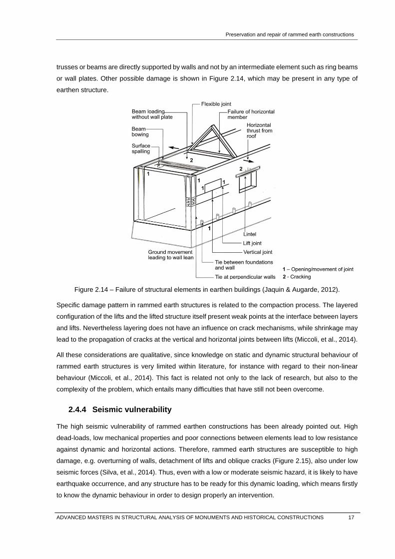
trusses or beams are directly supported by walls and not by an intermediate element such as ring beams
or wall plates. Other possible damage is shown in Figure 2.14, which may be present in any type of
earthen structure.
Figure 2.14 – Failure of structural elements in earthen buildings (Jaquin & Augarde, 2012).
Specific damage pattern in rammed earth structures is related to the compaction process. The layered
configuration of the lifts and the lifted structure itself present weak points at the interface between layers
and lifts. Nevertheless layering does not have an influence on crack mechanisms, while shrinkage may
lead to the propagation of cracks at the vertical and horizontal joints between lifts (Miccoli, et al., 2014).
All these considerations are qualitative, since knowledge on static and dynamic structural behaviour of
rammed earth structures is very limited within literature, for instance with regard to their non-linear
behaviour (Miccoli, et al., 2014). This fact is related not only to the lack of research, but also to the
complexity of the problem, which entails many difficulties that have still not been overcome.
2.4.4 Seismic vulnerability
The high seismic vulnerability of rammed earthen constructions has been already pointed out. High
dead-loads, low mechanical properties and poor connections between elements lead to low resistance
against dynamic and horizontal actions. Therefore, rammed earth structures are susceptible to high
damage, e.g. overturning of walls, detachment of lifts and oblique cracks (Figure 2.15), also under low
seismic forces (Silva, et al., 2014). Thus, even with a low or moderate seismic hazard, it is likely to have
earthquake occurrence, and any structure has to be ready for this dynamic loading, which means firstly
to know the dynamic behaviour in order to design properly an intervention.
ADVANCED MASTERS IN STRUCTURAL ANALYSIS OF MONUMENTS AND HISTORICAL CONSTRUCTIONS 17

Preservation and repair of rammed earth constructions
[1]
[2] [3]
Figure 2.15 – Typical earthquake-damage pattern in rammed earth buildings: [1] vertical cracking;
[2] Vertical cracking at corners; [3] In-plane shear cracking (Ziegert & Perrone, 2012).
Earthen materials are characterised by a post-peak and brittle behaviour. This means that once cracked,
the tensile strength of the wall is completely lost, but it can still have load bearing capacity as long as it
remains stable (Miccoli, et al., 2014). In this sense, the thickness of rammed earth structures contributes
to the general stability of the structure even when it is severely cracked. However, knowledge on the
structural behaviour of earthen buildings —particularly in the case of rammed earth— is still very limited,
and the implementation of adequate designs and interventions is not well developed.
By comparison with other techniques such as earth blocks, rammed earth walls provide more stability.
This is often related to a monolithic behaviour (Houben & Guillaud, 1989), but only in very few cases
these walls can strictly be considered this way (Miccoli, et al., 2014). Hence, the specificities of each
variant must be taken into account in the seismic assessment of historical rammed earth structures.
Aiming at identifying the influence of these specificities, few relevant studies have been carried out to
assess the performance of rammed earth walls under seismic loading (Vargas, 1993). Tested
parameters were: granulometry, moisture content, compaction level, use of additives, and presence of
materials between layers, i.e. additives and/or stabilisers such as lime, straw, stones or bricks. The use
of these materials as interface between lifts creates a weak point that forces the propagation of
horizontal cracks instead of diagonal, preventing collapse (Jaquin, 2008). These cracks may also appear
due to shrinkage even without any intermediate layer, acting in the same way (Miccoli, et al., 2014).
Other parameters may also entail a different structural behaviour, for instance the used formwork with
regard to the connection between walls. In earthen structures, induced seismic damage often occurs at
the comers due to weak connections between perpendicular walls (Silva, et al., 2014). Depending on
the type of formwork, corners have to be built differently whether using the front panel or not, and
differences may be significant. According to Vargas (1993) rammed earth walls have around 40% higher
resistance and deformation capacity in comparison with earth blocks.
18 ADVANCED MASTERS IN STRUCTURAL ANALYSIS OF MONUMENTS AND HISTORICAL CONSTRUCTIONS

Preservation and repair of rammed earth constructions
In any case, good seismic design is not only related to material properties but to the application of basic
constructive concepts, which could be applied to any kind of structure. They can be summarized as
follows (Ortega, et al., 2014):
- Avoid points of concentration of stresses. Better distribution of efforts through the whole section.
- Symmetric and uniform distribution of mass and stiffness. Regularity and continuity in plan and
elevation with regard to the distribution of openings.
- Ductility of the system with a good connectivity between elements.
- Improving connection between elements using proper devices such as ties.
- Alterations during previous restoration processes and/or maintenance, which can change the
global and local behaviour of the building.
These principles are based on the overall stability of the building, and therefore local mechanisms can
be prevented and global behaviour governed by in-plane walls can be developed. On the contrary,
conventional seismic retrofitting causes extensive alterations because they aim at upgrading the existing
structure. These alterations involve the installation of new systems that may result in problems of
material compatibility and so, of further damages.
In the same way, codes generally establishes that, in cases of rehabilitation, seismic retrofitting will be
considered so that the safety levels are higher than the originally conceived, but this approach is not
valid for any kind of historical structure. In the specific case of earthen structures, when seismic
regulations for earthen buildings do exist, e.g. in New Zealand, earthen techniques are tended to be into
one category (New Zealand Standard, 1998). In developing countries, where the most part of earthen
buildings is still present, these regulations are often based on conventional codes of developed
countries, and exclude earth as a building material (Cid, 2011).
In this context, the work carried out by researchers at the Catholic University of Peru (PUCP) is
remarkable. They have been investigating on the construction of earthen buildings in seismic areas for
about 40 years, and they were the first to write, in 1977, a seismic standard for earth construction. Within
the context of this research, and involving other institutions such as The Getty Conservation Institute,
the Catholic University of Peru has been carrying out extensive dynamic testing on adobe masonry
through the use of shaking table tests (Torrealva, et al., 2009). This research, among others, has been
carried out to assess the seismic vulnerabilities of the adobe masonry structures, which is the most
widespread earthen technique in Peru. However, with regard to the assessment of rammed earth
structures, there is still an important lack of research.
In Europe, the NIKER project —New Integrated Knowledge based approaches to the integrated
protection of cultural heritage from Earthquake-induced Risk— aimed at developing a new integrated
methodology for historical constructions that solves the above-mentioned problems, improving the
general safety level and reducing the loss of artistic value. Within this project, some institutions carried
ADVANCED MASTERS IN STRUCTURAL ANALYSIS OF MONUMENTS AND HISTORICAL CONSTRUCTIONS 19

Preservation and repair of rammed earth constructions
out specific research on the seismic behaviour of rammed earth structures, which in some cases is the
only reliable source of information on this specific field. However, with around 3000 pages of reports
between 18 participants worldwide, the final result is quite irregular (Università di Padova, 2012).
2.5 Conclusions
In the most developed countries, traditions are at the end of a process of decay. And in these societies,
earth belongs to local traditions, to the poor and popular architecture —nowadays called vernacular—,
and therefore, all related knowledge is lost. Earth is and was considered as a minor construction
material, and this is the root cause of the lack of understanding in the professional field, in academia
and therefore in society.
In recent times this trend is changing due to sustainability, identity and/or heritage awareness, and little
by little consciousness is growing within research institutions and professionals. In the field of heritage
conservation, however, this process is taking place in a very irregular way. A deep and multidisciplinary
approach is needed when re-understanding this architecture, while great monuments and most of
earthen architecture is located in the developing countries, where this heritage is strongly linked to
poorness. Therefore, to face a literature review on earthen architecture means to face a paradox: we try
to recover our lost knowledge in countries where this heritage is being abandoned by the local
population. And this paradox leads to a short, incomplete and generally poor state-of-the-art.
This entails a lack of consensus with regard to basic considerations and a short number of reliable
sources of information, both qualitative and quantitative. Furthermore, there are very few guidelines and
standards for experimental testing, so it is not possible to relate most of the published results. There
are, however, some exceptions like in Peru, where earthen architecture is still alive and where good-
quality research is being carried out for 50 years now.
These problems are not only related to the lack of research, but also to the difficulties that are still to
overcome. For instance, most of the experimental tests that aim at characterizing rammed earth are
performed in small wallets of homogenous layered and compacted earth, while reality is much more
complex and larger. These results may be valid for new and monolithic rammed earth walls, or for
specific research topics —as this thesis is—, but not for the characterization of historical constructions,
which are complex and extremely variable. An extensive testing campaign is, then, necessary, but the
size of the specimens is also a big issue.
Since an exhaustive literature review is out of the objectives of the present work, this Chapter aimed at
describing the state-of-the-art in those topics that are related to the objectives of the dissertation. In this
sense, only a brief outline of the problem has been presented due to the complexity of the topic.
However, it is important to stress, on the one hand, the necessity of fixing some basic concepts, and on
the other, the necessity of further research. It is, in short, the necessity of an essential understanding of
earthen materials.
20 ADVANCED MASTERS IN STRUCTURAL ANALYSIS OF MONUMENTS AND HISTORICAL CONSTRUCTIONS

Preservation and repair of rammed earth constructions
3. SURVEY ON RAMMED EARTH HERITAGE
3.1 Introduction
As a part of the experimental program of the present dissertation, a brief on-site investigation campaign
was carried out in Alentejo and Algarve, both regions in Southern Portugal. This program is expected to
become the initial state of a database focused on the study of the specific traditional architecture built
with rammed earth in these regions, especially with respect to their conservation condition and seismic
culture. More specifically, this campaign consisted on the study of 25 rammed earth buildings, mainly
focused on abandoned houses that presented some damage or were in ruin in order to facilitate the
identification of structural elements, and to assess possible causes of collapse.
The methodology is based on a statistical analysis, with brief general descriptions of the constructive
elements and causes of damage, and the analysis of the particularities of the rammed earth, namely
size of the used formwork, the use of lime and/or other stabilisers, a rough characterization of the soil
through visual inspection, and a short description of those structural elements that improve the seismic
behaviour of the building. As a result of this work, an inspection report was written for every building,
with basic information, plans and technical information.
3.2 Traditional architecture in Southern Portugal
The traditional architecture built with rammed earth walls —taipa— is of relevant importance in most of
regions in Southern Portugal, mainly in Alentejo, Algarve and Ribatejo. Rammed earth buildings can be
found in both rural and urban areas in different typologies, namely civil, military and vernacular buildings.
This technique was used until recent times with a wide diversity of variations adapted to the local
knowledge and local materials. Good examples can be found in Alcácer do Sal, Moura, Évora or Beja,
among many other locations.
3.3 On-site investigation
This study is out of the monumentality or relevance of important buildings, and it is mainly focused in
small rural/urban vernacular constructions. In order to clearly and easily identify structure and related
damage, the study was focused almost exclusively on abandoned constructions. The most common
typology corresponds to rural isolated courtyard houses of about 100 m2 of single and squared ground
floor, abandoned and in a state of partial ruin. Other studied buildings were warehouses and stockyards,
also in urban areas. Studied buildings are listed within Table 3.1 with a brief description of their main
characteristics, while their location is shown in Figure 3.1.
ADVANCED MASTERS IN STRUCTURAL ANALYSIS OF MONUMENTS AND HISTORICAL CONSTRUCTIONS 21
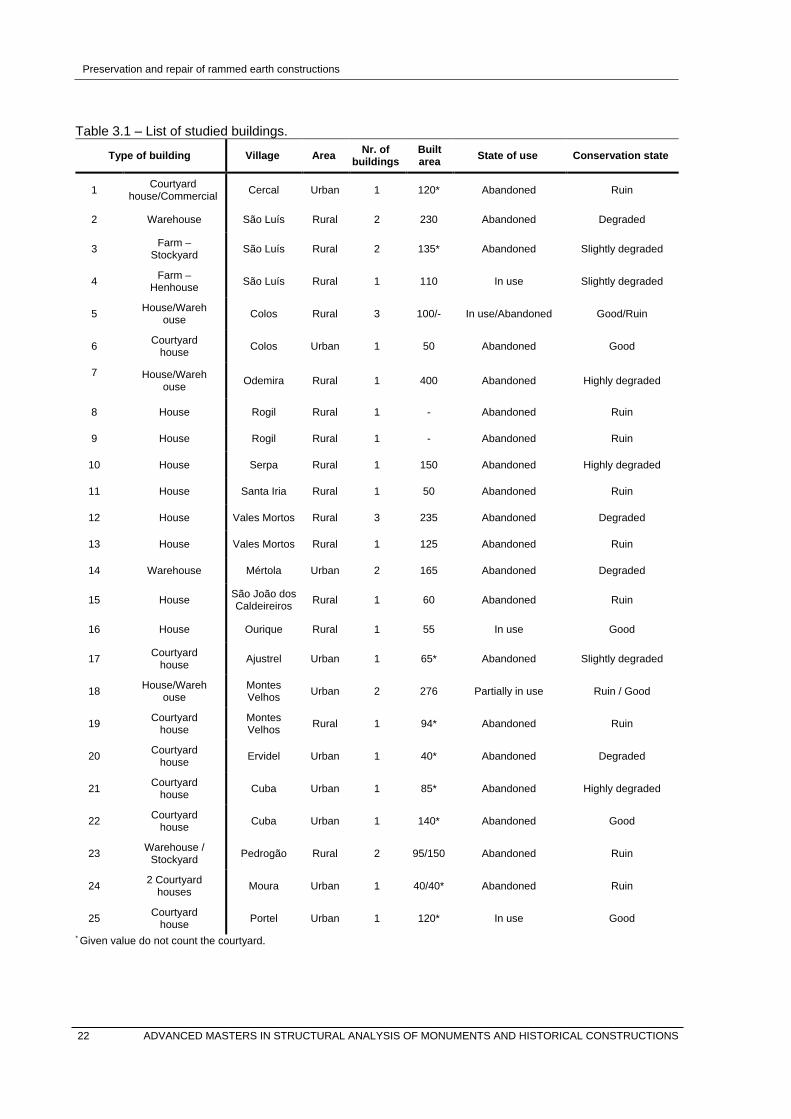
Preservation and repair of rammed earth constructions
Table 3.1 – List of studied buildings.
Type of building Village Area Nr. of buildings
Built area State of use Conservation state
1 Courtyard house/Commercial Cercal Urban 1 120* Abandoned Ruin
2 Warehouse São Luís Rural 2 230 Abandoned Degraded
3 Farm – Stockyard São Luís Rural 2 135* Abandoned Slightly degraded
4 Farm – Henhouse São Luís Rural 1 110 In use Slightly degraded
5 House/Warehouse Colos Rural 3 100/- In use/Abandoned Good/Ruin
6 Courtyard house Colos Urban 1 50 Abandoned Good
7
House/Warehouse Odemira Rural 1 400 Abandoned Highly degraded
8 House Rogil Rural 1 - Abandoned Ruin
9 House Rogil Rural 1 - Abandoned Ruin
10 House Serpa Rural 1 150 Abandoned Highly degraded
11 House Santa Iria Rural 1 50 Abandoned Ruin
12 House Vales Mortos Rural 3 235 Abandoned Degraded
13 House Vales Mortos Rural 1 125 Abandoned Ruin
14 Warehouse Mértola Urban 2 165 Abandoned Degraded
15 House São João dos Caldeireiros Rural 1 60 Abandoned Ruin
16 House Ourique Rural 1 55 In use Good
17 Courtyard house Ajustrel Urban 1 65* Abandoned Slightly degraded
18 House/Warehouse
Montes Velhos Urban 2 276 Partially in use Ruin / Good
19 Courtyard house
Montes Velhos Rural 1 94* Abandoned Ruin
20 Courtyard house Ervidel Urban 1 40* Abandoned Degraded
21 Courtyard house Cuba Urban 1 85* Abandoned Highly degraded
22 Courtyard house Cuba Urban 1 140* Abandoned Good
23 Warehouse / Stockyard Pedrogão Rural 2 95/150 Abandoned Ruin
24 2 Courtyard houses Moura Urban 1 40/40* Abandoned Ruin
25 Courtyard house Portel Urban 1 120* In use Good
* Given value do not count the courtyard.
22 ADVANCED MASTERS IN STRUCTURAL ANALYSIS OF MONUMENTS AND HISTORICAL CONSTRUCTIONS

Preservation and repair of rammed earth constructions
Figure 3.1 – Map of southern Portugal with the location of the studied buildings.
3.4 Structural survey
The main structural materials of the studied buildings were rammed earth for the load-bearing walls and
timber for the roof structure. The footing of walls, when present, were built with stone masonry, as well
as the reinforcement of the corners, built in some cases with brick masonry. Iron ties were also found
frequently, both embedded inside the walls or right next to them. Steel and reinforced concrete elements
were also used, together with brick masonry and concrete mortar, within the most recent interventions.
3.4.1 Walls
Walls were usually load-bearing rammed earth, but adobe was also found as well as brick and stone
masonry. Inner partition walls were originally built with a supporting grid structure of timber elements
ADVANCED MASTERS IN STRUCTURAL ANALYSIS OF MONUMENTS AND HISTORICAL CONSTRUCTIONS 23

Preservation and repair of rammed earth constructions
and reed canes, using earth mortar as infill (5). Some of the studied buildings presented recent additions
built with brick masonry and reinforced concrete in lintels and other constructive elements (1, 3, 5, 6, 7,
8, 14, 17, 18, 19, 21, and 24) (Figure 3.2).
Rammed earth was in some cases reinforced with stone masonry between blocks (1, 8, 20, 21, and 24),
while in the rest they were reinforced with a layer of lime mortar. Masonry was also used in corners (3,
14, 17, 18, 20, 21 and 23), as well as in window and door jambs. Stone masonry was also present in
footings, which had variable heights. However, it was observed that the lack of footing (1, 5, 10, 11, 14,
18, and 19) led to important damages related to overturning of the façade, differential settlements and
rising moisture.
Generally, it could be stated that the type of soil used was collected locally, but it was not possible to
determine exactly the origin in each case. In the case #20 a neighbour stated that the soil used for the
construction of the whole neighbourhood, and therefore also for the house, was collected from a single
source. In urban areas, the use of a common sources of soil located out of the villages is expected to
be usual, but it is something that should be confirmed in each case.
On the contrary, in rural areas it was collected in the immediate surroundings. Regarding the texture of
the soil, generally they were lean clayey soils with a high amount of medium gravels (1, 2, 3, 4, 5, 7, 10,
11, 15, 18, 20, 21, 22, 23, and 25). However, in some cases, the soil was even coarser (8, 12, 13, 14,
19, and 20), in some cases with high percentages of cobbles (Figure 3.2). In #12, the house was directly
built on the rock, in this case schist, and the rammed earth had very coarse fractions and a very low
content of finer fractions.
[1] [2]
Figure 3.2 – [1] Case study #10. Rural house in Serpa; [2] texture of the rammed earth. Case study
#13. Rural house in Vales Mortos.
The size of the block varied around 150 cm length, 30-50 cm height, and 50-60 cm width, but it was
heights of up to 20 cm were also found (1 and 18). The size of the compaction layers was not always
possible to determine, but in those cases in which they could be measured, they ranged between 10
and 25 cm. Rammed earth walls were mainly built with the use of front panels in the formwork, but
diagonal joints were also found. 24 ADVANCED MASTERS IN STRUCTURAL ANALYSIS OF MONUMENTS AND HISTORICAL CONSTRUCTIONS

Preservation and repair of rammed earth constructions
3.4.2 Roofs
Roofs were usually pitched or shed, in most cases. Roofs basically consist of a timber structure of joists
with reed-canes in between to support the upper layer of tiles, which are placed usually without any
mortar. Joists are supported directly by the rammed earth walls without any kind of additional element
such as perimeter beams. Other systems were found for instance in #23, with a central column with
timber beams, or #3 and #4, in which timber trusses were used.
Roof is usually the weakest part of a building, especially in traditional architecture, in which the
replacement of tiles was a process carried out every year or every two years. Any displaced or broken
tile means the origin of a decay process caused mainly by the action of rainwater, but biological agents
may also contribute to this process. The lack of maintenance accelerates this process, which leads
either to the collapse of the roof, or to the initial degradation of the wall. Any of these situations may
cause the ruin of the building, and this was the main cause in the studied buildings (Figure 3.3).
Figure 3.3 – Roof collapse. Case study #23. Stockyard in Pedrogão.
3.4.3 Plasters
All walls were originally rendered and plastered. The traditional material was lime mortar, but it was
substituted by cement mortar. Regarding their state of conservation, all studied buildings present loss
of material due to detachments or degradation caused by weathering and lack of maintenance.
3.5 Damage survey
As already mentioned, the main damage affecting the building is caused by rainwater. However,
mechanical damage due to the high dead-loads of the material were also remarkable, as well as failures
due to inappropriate footing.
ADVANCED MASTERS IN STRUCTURAL ANALYSIS OF MONUMENTS AND HISTORICAL CONSTRUCTIONS 25
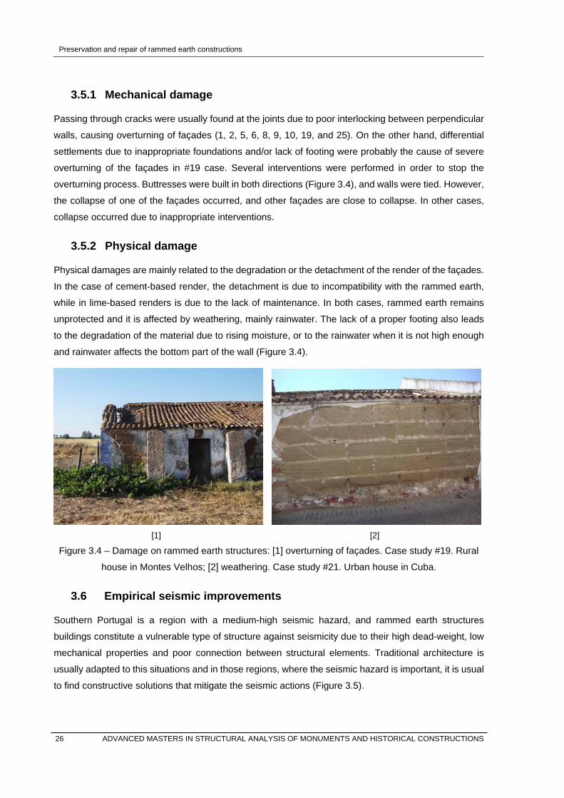
Preservation and repair of rammed earth constructions
3.5.1 Mechanical damage
Passing through cracks were usually found at the joints due to poor interlocking between perpendicular
walls, causing overturning of façades (1, 2, 5, 6, 8, 9, 10, 19, and 25). On the other hand, differential
settlements due to inappropriate foundations and/or lack of footing were probably the cause of severe
overturning of the façades in #19 case. Several interventions were performed in order to stop the
overturning process. Buttresses were built in both directions (Figure 3.4), and walls were tied. However,
the collapse of one of the façades occurred, and other façades are close to collapse. In other cases,
collapse occurred due to inappropriate interventions.
3.5.2 Physical damage
Physical damages are mainly related to the degradation or the detachment of the render of the façades.
In the case of cement-based render, the detachment is due to incompatibility with the rammed earth,
while in lime-based renders is due to the lack of maintenance. In both cases, rammed earth remains
unprotected and it is affected by weathering, mainly rainwater. The lack of a proper footing also leads
to the degradation of the material due to rising moisture, or to the rainwater when it is not high enough
and rainwater affects the bottom part of the wall (Figure 3.4).
[1] [2]
Figure 3.4 – Damage on rammed earth structures: [1] overturning of façades. Case study #19. Rural
house in Montes Velhos; [2] weathering. Case study #21. Urban house in Cuba.
3.6 Empirical seismic improvements
Southern Portugal is a region with a medium-high seismic hazard, and rammed earth structures
buildings constitute a vulnerable type of structure against seismicity due to their high dead-weight, low
mechanical properties and poor connection between structural elements. Traditional architecture is
usually adapted to this situations and in those regions, where the seismic hazard is important, it is usual
to find constructive solutions that mitigate the seismic actions (Figure 3.5).
26 ADVANCED MASTERS IN STRUCTURAL ANALYSIS OF MONUMENTS AND HISTORICAL CONSTRUCTIONS

Preservation and repair of rammed earth constructions
[1] [2]
Figure 3.5 – Seismic strengthening: [1] horizontal stones embedded in the wall. Case study #1. Rural
house in Cercal; [2] anchor plate. Case study #19. Rural house in Montes Velhos.
Ties together with anchor plates, and the reinforcement of the corners with masonry were solutions
observed in most of studied buildings (2, 5, 7, 14, 15, 16, 18, 19, and 23). An interesting finding observed
thanks to the collapse of the corner of #1 was the horizontal element embedded in the rammed earth
wall. This is an effective technique in which the horizontal elements act as seismic strengthening. All
described solutions aim at improving the box behaviour of the structure, avoiding out-of-plane
mechanisms and overturning of façades.
3.7 Conclusions
This experimental campaign allowed a first approach to the vernacular architecture in Alentejo and
Algarve. It was possible to confirm with case studies some concepts that have been pointed out thorough
Chapter 2, such as the vulnerability against earthquakes of rammed earth structures. In this sense, it
was possible to identify those traditional techniques that mitigate seismic actions in this type of
structures, and it is remarkable the wide use that was found within the studied cases.
With regard to the vulnerability of rammed earth to water, it was clearly stated that the lack of
maintenance in this architecture leads to collapse in a very short time. For this reason, it was not possible
to identify the relative importance of other causes of damage or decay, because in abandoned buildings
the action of water and the subsequent collapse of the roof masks any other possible symptom of decay.
This could be a further step within this research, to identify the importance of other causes of damage.
For instance within the assessment of the damage caused by salts or rising moisture; or which are the
specific urban solutions within the urban fabric used in the studied regions to prevent earthquake
damages.
ADVANCED MASTERS IN STRUCTURAL ANALYSIS OF MONUMENTS AND HISTORICAL CONSTRUCTIONS 27

Preservation and repair of rammed earth constructions
4. UNSTABILISED RAMMED EARTH ASSESSMENT
4.1 Introduction
This Chapter reports the assessment of those parameters that influence on the properties of unstabilised
rammed earth. As described in Chapter 2, properties mainly depend on the nature of the soil —defined
by texture, cohesion, and plasticity—, and on its compaction. Understanding the characteristics and the
properties of earth as a building material requires testing, both in field and in laboratory.
For this aim, soils termed as S5, S6 and SM will be characterised. The soil S5 corresponds to a soil
collected in the Alentejo region, in Portugal, and its suitability was assessed through a testing campaign
carried out in Silva (2013). Soil S6 is the resultant soil after correcting the granulometry of the soil S5,
following a procedure that is described in the mentioned work. The soil S6 was used in the manufacture
of the cylinders and wallets that will be tested. Finally, the soil SM corresponds to a soil collected from
an existing rammed earth building in the M’Hamid Oasis, in Southern Morocco. In the same way, main
tests will be performed and described, and the results will be compared with the obtained values of soils
S5 and S6.
The assessment process and results of all mentioned soils will be compared, when possible, with the
recommended values given by the German Code —Lehmbau Regeln—, in order to assess the suitability
of the soil for rammed earth (Dachverband Lehm e.V., 2009). This code was initially published in 1999,
becoming a reference in Europe, and it is one of the most comprehensive guidelines worldwide. It
describes the general requirements of earth construction, the type of suitable soils and properties, and
the description of the main construction techniques, as well as design procedures and
recommendations. Chapters referred to earth blocks construction, earthen mortars and earthen plasters
reached the status of national DIN standard in 2013, while the complete code is in process of validation.
4.2 Soil identification
Soil is the raw material of unstabilised earth, so the properties of earthen materials are determined by
the nature of the soil. Nevertheless not all soils can be used for earth construction, and some are more
suitable than others for a given technique. Traditionally, this was one of the factors that influenced the
use of one specific technique, since correcting the material resulted a difficult task.
Nowadays soil specifications are defined in standards and guidelines, but they can widely vary
depending on the source. This is because soils cannot have an optimum behaviour with regard to all
properties, and every code and standard may give more importance to one or another depending on
their specific criteria. The German Code specifies the suitability of soils together with the detailed
description of appropriate selection tests. This code also describes the requirements and properties of
rammed earth as construction material, as well as the requirement of the constructive elements.
28 ADVANCED MASTERS IN STRUCTURAL ANALYSIS OF MONUMENTS AND HISTORICAL CONSTRUCTIONS

Preservation and repair of rammed earth constructions
4.2.1 Texture and cohesion
The most accepted tests used to determine the granulometry are the dry sieving methods, which defines
the texture, and the sedimentation test to establish the fine fraction. Dry sieving consists on separating
the soil fractions through sieves up to the fines (Figure 4.1). Below this size, the sedimentation test is
required, which is based in the change of density of water while particles in suspension are settling
(LNEC, 1966). Both tests give quantitative information about the constituent grain sizes, and therefore
the PSD curve can be determined.
However, all particles under 0.002 mm are considered as clays, but not all these particles have cohesive
properties, as stated in Chapter 2. Furthermore kaolinite can exhibit particle sizes of more than 0.002
mm (Röhlen & Ziegert, 2014), and the binding strength of a soil may widely vary depending of the type
of clay minerals.
Figure 4.1 – Soil SM after dry sieving.
Therefore, these tests may be not suitable for the precise assessment of specific soils. For these cases,
the German Code recommends the cohesion test for an accurate quantitative analysis of the cohesion
of the soil, which is a wet tensile test using 8-shaped samples. This test allows the measurement of the
tensile strength of a moist soil, which results are classified in the code in order to assess its suitability
(Dachverband Lehm e.V., 2009).
In the case of rammed earth, the German Code determines a minimum binding force with regard to the
cohesion, and an optimal particle size distribution composed of 15% of clays, 30% of silt and 55% of
sands and gravels —any fraction coarser than 20 mm is sieved out. This granulometry defines a stony-
clay texture of the obtained mixture (Figure 4.2). This distribution is determined according to the modified
Fuller Formula (Equation 4.1), which gives and ideal grain distribution for earthen materials with a 15%
of clays fraction (Röhlen & Ziegert, 2014).
ADVANCED MASTERS IN STRUCTURAL ANALYSIS OF MONUMENTS AND HISTORICAL CONSTRUCTIONS 29
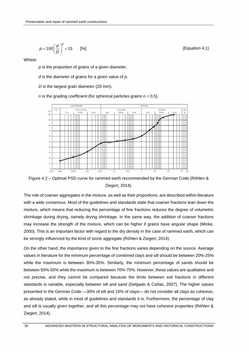
Preservation and repair of rammed earth constructions
100 15
ndpD
= +
[%] (Equation 4.1)
Where:
p is the proportion of grains of a given diameter.
d is the diameter of grains for a given value of p.
D is the largest grain diameter (20 mm).
n is the grading coefficient (for spherical particles grains n = 0.5).
Figure 4.2 – Optimal PSD curve for rammed earth recommended by the German Code (Röhlen &
Ziegert, 2014).
The role of coarser aggregates in the mixture, as well as their proportions, are described within literature
with a wide consensus. Most of the guidelines and standards state that coarser fractions lean down the
mixture, which means that reducing the percentage of fine fractions reduces the degree of volumetric
shrinkage during drying, namely drying shrinkage. In the same way, the addition of coarser fractions
may increase the strength of the mixture, which can be higher if grains have angular shape (Minke,
2000). This is an important factor with regard to the dry density in the case of rammed earth, which can
be strongly influenced by the kind of stone aggregate (Röhlen & Ziegert, 2014).
On the other hand, the importance given to the fine fractions varies depending on the source. Average
values in literature for the minimum percentage of combined clays and silt should be between 20%-25%
while the maximum is between 30%-35%. Similarly, the minimum percentage of sands should be
between 50%-55% while the maximum is between 70%-75%. However, these values are qualitative and
not precise, and they cannot be compared because the limits between soil fractions in different
standards is variable, especially between silt and sand (Delgado & Cañas, 2007). The higher values
presented in the German Code —30% of silt and 15% of clays— do not consider all clays as cohesive,
as already stated, while in most of guidelines and standards it is. Furthermore, the percentage of clay
and silt is usually given together, and all this percentage may not have cohesive properties (Röhlen &
Ziegert, 2014).
30 ADVANCED MASTERS IN STRUCTURAL ANALYSIS OF MONUMENTS AND HISTORICAL CONSTRUCTIONS

Preservation and repair of rammed earth constructions
In addition, the normalized dry sieving test uses a diameter of 0.075 mm for the fine fractions through
the ASTM sieve #200, which means that the assessment of the cohesion using the PSD curve takes
into consideration a fraction of clay and silt up to 0.075 mm. On the other hand, the German Code is
based on the standard DIN 18123 (ISO, 2013), which uses a sieve of 0.063 mm. In the assessment of
the cohesion, the ribbon test was used. This is a qualitative test consisting on the shaping of a cylinder,
which is flattened to produce a ribbon. The length of this cylinder before breaking can be related to the
content of clay minerals and related to the suitability of the soil for earthen techniques.
Other qualitative tests that give an estimation of the soil granularity were performed, such as visual
examination and dry strength test (Silva, 2013). These tests give a fast and simple approximation to
determine the suitability of soils, are they are considered by the German Code as supplementary tests.
Characterization of the selected soils
The granulometry of all studied soils are based on the Portuguese standards (LNEC, 1966), and are
described in (Table 4.1). The soil SM was characterized using the dry sieving method for the fractions
coarser than 0.075 mm and sedimentation to define the fine fraction. The granulometry of the soil S5
was corrected following the recommendations given by the CRATerre-EAG (Houben & Guillaud, 1989)
for rammed earth.
Figure 4.3 – PSD curve of the soil SM.
Table 4.1 – PSD of soils S5 and S6 (Silva, 2013), and soil SM compared with the German recommendations for rammed earth (Dachverband Lehm e.V., 2009).
Clay Silt Sand Gravel Cobble
[%] [%] [%] [%] [%]
Soil S51 28 31 23 15 3
Soil S61 14 16 32 37 1
Soil SM1 18 24 68 - -
German Code2 15 30 15 40 0 1 Clay < 0.002 mm / 0.002 mm ≤ silt < 0.075 mm / 0.075 mm ≤ sand < 2.0 mm / 2.0 mm ≤ gravel < 20 mm / cobbles ≥ 20 mm. 2 Clay < 0.002 mm / 0.002 mm ≤ silt < 0.063 mm / 0.063 mm ≤ sand < 2.0 mm / 2.0 mm ≤ gravel < 20 mm / cobbles ≥ 20 mm.
ADVANCED MASTERS IN STRUCTURAL ANALYSIS OF MONUMENTS AND HISTORICAL CONSTRUCTIONS 31

Preservation and repair of rammed earth constructions
From the resultant PSD curve of the soil SM it is possible to state that the percentage of silt and sands
is very high —24% and 68% respectively— and also a relatively high content of clays —18%. During
the test the whole quantity of soil passed through the ASTM sieve #10, and therefore the soil does not
present any gravel size fraction. The suitability of this soil in terms of granulometry for rammed earth
would be low according to the German Code, and should be corrected with the addition of coarser sands
and gravels.
With regard to the soil S5, the contents of clays was very high and it was corrected with the addition of
coarser aggregates in order to optimize its strength performance (Silva, 2013). The resultant
granulometry of soil S6 does not fit exactly with the recommendations of the German Code, but as
mentioned before, every standard and guideline adopt different criteria depending on the importance
given to the properties of the material. In the assessment of the cohesion, the length of the cylinder of
soil S6 was 51 mm in the ribbon test, which according to the guidelines, means a low to moderate
amount of clay, which is suitable for rammed earth.
4.2.2 Plasticity
The importance of the moisture content on the dry properties and the behaviour of soils has been already
discussed. Soil plasticity, which is indicated with the Plasticity Index —IP—, is related to the ability of a
soil to deform while resisting an increase in loading. The water content is used to classify soils, which
are defined with limits of consistency known as the Atterberg limits. These are: Liquid Limit —WL—,
Plastic Limit —WP—, and Shrinkage Limit —WS.
The liquid limit is the water content at which the soil-water mixture changes from a liquid to a plastic
state. As the water content decreases, the soil passes into a semisolid state at the plastic limit, and a
solid state at the shrinkage limit. Up to the semi-solid state, reduction in the volume of soil is nearly
equal to the volume of water lost, and the shrinkage limit defines the point at which the volume of the
soil becomes nearly constant with further decreases in water content.
The properties of earthen materials are correlated to the liquid and plastic limits, which are more
commonly used. The plasticity index is the numerical difference between liquid and plastic limits
(Equation 4.2), and it can be taken as indicative of the clay content and/or the activity of these clays.
Therefore, higher plasticity index is indicative of higher clay content and/or active clay mineral, and its
value is directly correlated with properties such as the shrinkage that will occur when earth dries.
P L PI w w= − [-] (Equation 4.2)
Some guidelines, for instance Houben & Guillaud (1989), also consider the shrinkage limit, which is
linked with plasticity-based soil behaviours, but such correlations exhibit poor performance and the
definition of this limit is being reviewed. Recent studies state that the shrinkage limit of a natural soil
does not depend upon plasticity characteristics, but it is primarily governed by the relative grain size
distribution of the soil (Sridharan & Prakash, 2000).
32 ADVANCED MASTERS IN STRUCTURAL ANALYSIS OF MONUMENTS AND HISTORICAL CONSTRUCTIONS

Preservation and repair of rammed earth constructions
In any case, the recommendations of Houben & Guillaud (1989) are the most widespread worldwide,
and they are assumed by other guidelines and standards, as well as by the German Code. The liquid
limit can be determined in laboratory using the Casagrande shell method, in accordance with the
standard ISO 17892 (ISO, 2004) (Figure 4.4). On the other hand, the plastic limit can be determined
with the thread-rolling test, in accordance with the standard ISO 17892 (ISO, 2004). This test consists
on the roll of small ribbons until they break at about 3 mm diameter. In those cases in which it is not
possible to perform this test, the soil is considered non-plastic.
Figure 4.4 – Determination of the Liquid Limit of Soil SM with the Casagrande shell method.
Characterization of the selected soils
In the case of soil S6, the consistency is outside the recommended parameters due to a low content of
clays (Figure 4.5), and therefore a low index of plasticity (Table 4.2). Considering these values, the soils
5 and 6 are classified as a Sandy Low Plasticity Clay —saCll— (ISO, 2013). The soil SM presents a
very low plasticity index —less than 5—, and therefore the plasticity of the soil can be disregarded. This
soil is classified as Low Plasticity Silt soil —Sil.
Table 4.2 – Atterberg limits of soils S5 and S6 (Silva, 2013), soil SM, and recommended values.
WL WP IP Classification (ISO)
[%] [%] [%]
Soil S5 30 18 12 saCll
Soil S6 23 16 7 saCll
Soil SM 20 18 2 Sil
Recommended (Houben & Guillaud, 1989)
30-35 12-22 18-13 -
ADVANCED MASTERS IN STRUCTURAL ANALYSIS OF MONUMENTS AND HISTORICAL CONSTRUCTIONS 33

Preservation and repair of rammed earth constructions
Inde
x of
Pla
stic
ity [%
]
Liquid Limit [%]
Figure 4.5 – Consistency of soils S5, S6 and SM compared with recommended ranges of values.
4.2.3 Compaction
As mentioned in Section 2.3.3, an important parameter determining the compressive strength of rammed
earth is the dry density of the soil, i.e. the bulk density, which depends on the type of soil, the moisture
content during the compaction process, and the energy of compaction. This process consists on
pressing together the soil particles, reducing the air voids and thus increasing the dry density of the soil.
For a particular compaction energy given, there is an Optimum Water Content —OWC— that allows the
maximum compaction. The Proctor test is used to determine the dry density and the water content
achieved with a compaction energy, and it is described within the standard DIN 18127 (DIN, 2012),
among others. This test consists on testing at least 5 samples of soils with different water content, in
moulds of standard capacity and compacted with a standard energy. The water content and dry densities
are calculated and plotted on a graph. From the resultant curve, it is possible to quantitatively determine
the optimum water content for which the soil experiences its maximum dry density for a given
compaction energy. However, the convenience of this test is controversial. According to the Australian
earth building handbook (Standards Australia, 2002) the use of this test entails some difficulties, since
the calculated compaction energy may be difficult to apply accurately in the construction site. Within the
same guideline it is also argued that the compaction energy of the standard Proctor is too low in
comparison with the required force applied on site, while other authors state that it gives a good
estimation of the dry density achieved with the use of manual rammers (Velde, 2008).
Furthermore, some guidelines also state that compacting under static force is less effective than
ramming while vibrating —dynamically applied forces—, which allows the particles to settle into a denser
pattern (Minke, 2000). On the contrary, Velde (2008) argues that dynamic compaction gives lower
mechanical resistance than static compaction. None of these authors offer further experimental data.
Regardless of the validity or not of these statements, what it seems to be clear is that the content of
water during compaction, and thus the achieved dry density, are of higher importance on the
performance of rammed earth. However, in the same way, it is significant to consider that the water
34 ADVANCED MASTERS IN STRUCTURAL ANALYSIS OF MONUMENTS AND HISTORICAL CONSTRUCTIONS

Preservation and repair of rammed earth constructions
content will rapidly change during the drying process after compaction, but also over time due to the
high hygroscopic behaviour of the material. Therefore, it is important to consider not only the ideal
conditions given by the Proctor but also the influence of these initial conditions on the drying process
that undergoes after compaction.
At this point, it is interesting to remark the research carried out by Schroeder (2011), in which the
influence of drying times in the final strength of the rammed earth is assessed. This work states that the
water content given by the standard Proctor test during compaction is not generally the optimum level
for the rapid drying process that occurs subsequently. In this sense, higher levels of initial moisture
content can accelerate the drying process and lead to higher strength. In the same way the presence of
coarse aggregates and straw also increase the initial drying. As a conclusion, the water content during
compaction should be of about 10% higher than the OWC given by the Proctor test in order to allow an
optimum drying process and therefore higher strength values.
In any case, a reasonable first approximation to the optimum water content can also be achieved with
other tests such as the Drop Test Water Content —DTWC—. A ball of moist soil, of approximately 40
mm diameter, is compacted by hand. The soil ball is dropped from a height of approximately 1.5 m.
When enough water has been added so that the ball breaks into only a few pieces, the DTWC is
acceptable and the mixture is suitable for rammed earth. If the ball remains in one piece then the soil is
too wet, while if it is too dry, the ball breaks in many pieces. Even if the drop test is qualitative and an
approximate test, it provides a water content very close to the OWC. For this reason, together with the
difficulties related with the use of the Proctor test above mentioned, the German Code considers the
drop test a reliable way of controlling soil water content during construction.
Characterization of the selected soils
In the case of soils S5 and S6, both Proctor and drop tests have been carried out, with similar results
for the water content. These results are presented in Figure 4.6 and are summarized in Table 4.3, being
compared with those values recommended by Houben & Guillaud (1989). For the assessment of soil
SM, the standard Proctor test was not used because the amount of material necessary to perform this
test was higher than the collected amount of soil.
Table 4.3 – Compaction properties of soils S5 and S6 (Silva, 2013), and soil SM
ρmax OWC Gs DTWC
[g/cm3] [%] [-] [%]
Soil S5 1.83 13.4 2.68 15.9
Soil S6 2.10 10.1 2.68 9.7
Soil SM 1.65-1.751 14-151 - 15.2
Recommended (Houben & Guillaud, 1989)
1.8-2 5-15 - -
1 Approximated values given as a reference in the UMinho Structures laboratory.
ADVANCED MASTERS IN STRUCTURAL ANALYSIS OF MONUMENTS AND HISTORICAL CONSTRUCTIONS 35

Preservation and repair of rammed earth constructions
Dry
den
sity
[g/c
m3 ]
Water content [%]
Figure 4.6 – Compaction curve of soils S5 and S6 (Silva, 2013).
4.2.4 Durability
The durability of earthen materials is mainly related to the action of water on the walls, which can be
tested and assessed in laboratory. Testing procedures mainly consist on the spray test and the drip test,
which are modified from generic tests in order to adapt them to earthen materials. However, accidental
abrasion is also a significant agent of deterioration and may affect to the durability. The resistance of
surfaces can be measured with a procedure developed the University of Kassel in Germany (Figure
4.7). This test consist on brushing the surface and weighing the amount of abrasion (Minke, 2011).
Figure 4.7 – Results of abrasion test conducted with laboratory test apparatus (Minke, 2011).
All these tests aim at assessing the durability of the material, but it is necessary to take into account that
traditional earthen architecture is usually plastered, and in new buildings it is strongly recommended,
since it is an excellent way of protecting external walls against weathering. Therefore, these tests are
relevant only in those cases where the structure is not plastered, or when it is necessary to assess the
suitability of plasters, which is actually a different earthen material with different requirements and
characterization.
0 4 8 12 16 201.6
1.7
1.8
1.9
2.0
2.1
2.2Standard Proctor
Ec= 6058 g.cm/cm3
Gs= 2.68
Soil S5 Soil S6
36 ADVANCED MASTERS IN STRUCTURAL ANALYSIS OF MONUMENTS AND HISTORICAL CONSTRUCTIONS

Preservation and repair of rammed earth constructions
4.3 Mechanical properties
As already stated, the mechanical strength of soils mainly depends on compaction; binding forces of
mineral clays; relative proportion between clays and aggregates, and the water content of the mixture.
The dry density is a parameter that relates all these factors, and thus, it is an important reference value.
Thus, in the same way that it is difficult to give exact values for the dry density, it is impossible to
determine the strength only without performing tests in laboratory.
In order to determine the mechanical parameters of the rammed earth, two sets of uniaxial compressive
and diagonal compressive tests will be performed with cylinders and wallets that were previously
manufactured. The testing process of the wallets will be recorded and analysed with Digital Image
Correlation —DIC— technique, which is an image analysis method that can determine the
displacements of an object under loading. This system allows a better understanding about local and
global strain distribution and about cracks before they initiate (Hild & Roux, 2012). It requires of a
stochastic intensity pattern on the object surface, in order to identify and determine the displacement of
each point. This is the reason why one of the surfaces of the wallets were painted in white and sprayed.
4.3.1 Uniaxial compression test
The procedure for the uniaxial compressive tests varies according to the standard and the type of
specimen. In the case of the assessment of the soil S6, six cylindrical specimens were manufactured
(Figure 4.8), namely from CURE_1 to CURE_6, with a water content adjusted according to the drop
test. The compaction was carried out in three layers inside a metallic mould with 100 mm diameter and
200 mm height and using an electric rammer in order to compact the specimen with the maximum moist
density obtained from the standard Proctor test as a value of reference —2.21 g/cm3.
Figure 4.8 – Set-up of the uniaxial compressive test.
ADVANCED MASTERS IN STRUCTURAL ANALYSIS OF MONUMENTS AND HISTORICAL CONSTRUCTIONS 37

Preservation and repair of rammed earth constructions
Tests were performed after the storage of the specimens at 20ºC and 57.5% of relative humidity during
approximately 9 months, in order to reach the equilibrium water content (Silva, 2013). Once the
specimens were prepared, a monotonic load was applied with a constant velocity of 0.003 mm/s until
failure occurs, and the deformations at the middle third part of the specimens were measured with three
radial displacement transducers —LVDT. An additional transducer was necessary to measure the
velocity of loading, since it is too low to be measured directly through the loading jack.
Table 4.4 – Results of the cylinders tested under compression.
Specimen W WEQ ρd fc E
[%] [%] [g/cm3] [MPa] [MPa]
CURE_1 8.3 0.7 2.05 1.24 595
CURE_2 7.5 0.6 2.06 1.48 712
CURE_3 7.1 0.7 2.07 1.57 606
CURE_4 7.0 0.6 2.08 1.66 358
CURE_5 7.3 0.6 2.07 1.59 495
CURE_6 8.1 0.4 2.05 1.49 428
Average 7.6 0.6 2.07 1.50 536
CoV [%] 7.1 14.1 0.5 8.8 22.6
The resultant stress-strain curves of this test are presented in Figure 4.9.
Figure 4.9 – Stress-strain curves of the six cylindrical specimens, CURE_1 to CURE_6.
The average compressive strength —fc— of the six cylindrical specimens is of about 1.50 MPa, with
values in a range of 1.24 and 1.57 MPa. The modulus of elasticity —E0— was computed between the
5% and 30% of the fc and the strain —γ— by linear fitting. The obtained average value for the six
specimens is 531.53 MPa, with minimum values of 358.2 and 712.52 MPa respectively (Table 4.4).
0,0
0,2
0,4
0,6
0,8
1,0
1,2
1,4
1,6
1,8
0 2 4 6 8 10 12 14 16 18
Stre
ss [M
Pa]
Strain [mm/m]
CURE_1
CURE_3
CURE_2
CURE_6
CURE_4
CURE_3
38 ADVANCED MASTERS IN STRUCTURAL ANALYSIS OF MONUMENTS AND HISTORICAL CONSTRUCTIONS

Preservation and repair of rammed earth constructions
The resultant compressive strength was slightly higher than the average values obtained within the
testing campaign performed in Silva (2013) for soil S6 —fc = 1.2 MPa. With regard to the modulus of
elasticity, the obtained values are about the half of the mean values obtained within the mentioned work,
but given the variability in the results, it can be considered as an acceptable result. The differences of
density and water content with respect to these values of reference may be due to the manufacture
process of the specimens.
Figure 4.10 – Failure mode of the specimen CURE_6 with the formation of a main diagonal crack.
The failure of the specimens always occurred with the initiation and propagation of a main vertical and
diagonal crack (Figure 4.10). The failure pattern of the specimens tested in Silva (2013) showed also
material crushing and consequent disaggregation, which was not observed in the current tests.
According to this study, the differences between the two modes of failure depend on the compaction
water content.
With regard to the suitability of the soil S6 for rammed earth, there is not a clear value of reference within
literature. The permissible compressive strength of earthen building elements according to the standard
DIN 18954 is between 3 and 5 MPa (Dachverband Lehm e.V., 2009). However, according to Minke
(2000) in practice this value would be necessary only on specific elements in 2-storey buildings or
higher. On the contrary, other guidelines state that values higher than 2 MPa satisfy the requirements
in the majority of standards (Houben & Guillaud, 1989).
Some codes and standards use the characteristic unconfined compressive strength to determine the
suitability of earth as construction material (Equation 4.3), which depends on a partial safety factor that
varies between standards. The New Zealand Standard NZS 4298 (New Zealand Standard, 1998),
considers a partial safety factor of 0.60 for axial compression and bearing. Considering this value, the
characteristic unconfined compressive strength can be calculated as follows:
ADVANCED MASTERS IN STRUCTURAL ANALYSIS OF MONUMENTS AND HISTORICAL CONSTRUCTIONS 39

Preservation and repair of rammed earth constructions
' ·c cf fφ= [%] (Equation 4.3)
Where:
fc’ is the characteristic compressive strength.
φ is the partial safety factor (the New Zealand Standard considers φ = 0.6).
fc is the average compressive strength.
Hence, the characteristic compressive strength —fc’— is 0.90 MPa, which is higher than the minimum
value recommended by the New Zealand Standard, 0.5 MPa. With regard to the suitability of the
modulus of elasticity, the New Zealand Standard considers as a good value of reference 300 times the
characteristic compressive strength value. According to this, the obtained modulus of elasticity, which
is of about 466 the times characteristic compressive strength, is valid for rammed earth structures.
4.3.2 Flexural bending strength
Since no experimental testing was carried out to obtain flexural bending strength, the recommendations
given by the New Zealand Standards are followed. According to the New Zealand Standard, the
characteristic bending strength is equal to 10% of the characteristic compressive strength, for materials
with compressive strength less than 6 MPa. The flexural bending strength —ft— is, then, 0.09 MPa,
which is less than the minimum considered by the same standard when no experimental results are
available at all. Other guidelines recommend ignoring any material strength in bending.
4.3.3 Diagonal compression tests
This test was performed in accordance to the ASTM E519-02 standard (ASTM, 2002). It is used to
determine the shear strength and shear modulus of small specimens of masonry, and was adapted for
the test of rammed earth wallets. For this work, six specimens of 550x550x200 mm3 were manufactured,
with nine layers of earth compacted with an electric rammer. The water content was determined with
the drop test, and testing was performed after a drying period of about 9 months under laboratory
ambient conditions, with a temperature of about 22±2 ºC (Silva, 2013).
The wallets were positioned in the testing machine with a diagonal axis in the vertical direction and
loaded in compression along this direction. According to the ASTM standard, test setup is composed of
two standardised steel loading supports in order to avoid failure due to excessive localised compression
stress at the corners. The load was applied monotonically until failure of the specimen with a velocity of
0.003 mm/s, which was controlled with a specific transducer. In order to measure the shortening of the
vertical diagonal and the lengthening of the horizontal diagonal, two displacement transducers were
placed on the mid-third of the total length in one side of the specimen (Figure 4.11).
40 ADVANCED MASTERS IN STRUCTURAL ANALYSIS OF MONUMENTS AND HISTORICAL CONSTRUCTIONS

Preservation and repair of rammed earth constructions
[1] [2]
Figure 4.11 – Test setup of the diagonal compression tests: [1] test apparatus; [2] placement of the
LVDTs.
Following the ASTM standard, the shear stress — fs— (Equation 4.4) and the shear strain —γs—
(Equation 4.6), can be calculated as follows:
0.707s
n
PfA
= [MPa] (Equation 4.4)
Where:
P is the maximum applied load.
An is the net area of the specimen, calculated as follows (Equation 4.5).
· ·
2nw hA t n+ =
[mm2] (Equation 4.5)
Where:
w, h, and t are respectively the width, height, and thickness of the wallet.
n is the percentage of the gross area of the unit that is solid, expressed as a decimal (n = 1).
2
V Hs
V HL Lγ
∆ + ∆=
+
[mm/m] (Equation 4.6)
Where:
∆V and ∆H are the vertical and horizontal shortening.
LV and LH are the vertical and horizontal gage length.
ADVANCED MASTERS IN STRUCTURAL ANALYSIS OF MONUMENTS AND HISTORICAL CONSTRUCTIONS 41

Preservation and repair of rammed earth constructions
Table 4.5 – Results of the wallets tested under diagonal compression.
Specimen W WEQ ρd fS G
[%] [%] [g/cm3] [MPa] [MPa]
WURE_1 8.8 1.0 2.05 0.12 1055
WURE_2 9.2 1.1 2.04 0.16 1356
WURE_3 9.1 0.9 2.04 0.16 632
WURE_4 9.5 0.9 2.04 0.13 1068
WURE_5 8.9 1.0 2.05 0.12 459
WURE_6 9.0 0.9 2.05 0.11 71*
Average 9.1 1.0 2.04 0.13 914
CoV [%] 2.9 5.8 0.4 14.3 35.4
The shear modulus G, i.e. modulus of transversal stiffness, is computed by linear fitting of the respective
stress-strain curve between the 5% and the 30% of the shear strength value. The average shear
modulus was 914.5 MPa, with values that range between 459.7 and 1356.6 MPa with a coefficient of
variation of 35%. The shear modulus obtained in the WURE_6 was not considered, because of the high
percentage of deviation from that of the others specimens. This invalid result may be due to failures
during the measurement process, such as an incorrect placement of the transducers. With regard to the
obtained shear strength, results were more consistent, with values in the range of 0.11 and 0.17 MPa,
with an average value of 0.13 MPa and a coefficient of variability of 14% (Table 4.5).
Regarding the dry density of the rammed earth, it is similar to the obtained in the uniaxial compressive
test, and the variations with regard to the values given by the Proctor test may be also due to the
manufacture process. For the same reason, the water content is slightly lower than the measured in the
cylinders (Silva, 2013). On the contrary, the equilibrium water content is doubled, probably due to the
different ambient conditions of the drying process (Table 5.7). As discussed in Section 4.2.3, these
parameters are significant in terms of the mechanical performance of rammed earth, but it was not
possible to assess the real influence in the obtained results.
In comparison with other values found in literature, the obtained shear strength is very similar to the
obtained in Silva (2013), where the average value was of about 0.15 MPa. This is expectable, since the
conditions of the tests were very similar. However, the average value for the shear modulus is slightly
lower in the mentioned work, of about 639.5 MPa, but this difference could be considered as acceptable
considering the high variability of all the obtained values. According to Miccoli, et al. (2014), the obtained
shear strength is 0.71 MPa, while the shear modulus is 2326 MPa. In both cases the values are much
higher than those obtained in the present work. However, these results are not directly comparable,
since the conditions of the test may vary. In any case, the variability could be very high due to the type
of soil used, which in the case of the mentioned study it was provided by a manufacturer.
42 ADVANCED MASTERS IN STRUCTURAL ANALYSIS OF MONUMENTS AND HISTORICAL CONSTRUCTIONS

Preservation and repair of rammed earth constructions
Figure 4.12 – Stress-strain curves of the six wallets before injection, WURE_1 to WURE_6.
The typical stress-strain curve of all tested wallets has an elastic range until the first vertical crack
appears, followed by a long post-peak phase. At the beginning of the plastic phase, an initial short
softening is followed by long hardening and softening phases (Figure 4.12). The high plasticity is mainly
due to the interlocking of the coarse particles of the rammed earth. After the initial crack, which is
developed not only along joints but also through layers, new cracks continued developing through the
hardening and softening post peak phases, showing high ductility of the material. Cracks also appeared
through the interface between layers, which is a weak point where concentration of stresses is produced.
Additionally for WURE_2 and WURE_4, a DIC analysis was carried out to evaluate the deformation of
the wallets during the test. The results of this analysis are presented together with the corresponding
stress-strain curve, with yellow and red colours indicating cracking (Figure 4.13 to Figure 4.17).
Figure 4.13 – Stress-strain curve of the wallet WURE_2.
0,00
0,02
0,04
0,06
0,08
0,10
0,12
0,14
0,16
0,18
0,20
0 2 4 6 8 10 12 14 16 18 20
Stre
ss [M
Pa]
Strain [mm/m]
0,00
0,02
0,04
0,06
0,08
0,10
0,12
0,14
0,16
0,18
0,20
0 5 10 15 20 25 30
Stre
ss [M
Pa]
Strain [mm/m]
WURE3
WURE2
WURE5
WURE6
WURE4 WURE1
1 2 3
4
ADVANCED MASTERS IN STRUCTURAL ANALYSIS OF MONUMENTS AND HISTORICAL CONSTRUCTIONS 43

Preservation and repair of rammed earth constructions
[1] [2]
[3] [4]
Figure 4.14 – Resultant maximum principal strains from the DIC analysis of WURE_2.
Figure 4.15 – Results from the DIC analysis of WURE_4.
0,00
0,02
0,04
0,06
0,08
0,10
0,12
0,14
0,16
0,18
0,20
0 5 10 15 20 25 30
Stre
ss [M
Pa]
Strain [mm/m]
1 2 3 4
44 ADVANCED MASTERS IN STRUCTURAL ANALYSIS OF MONUMENTS AND HISTORICAL CONSTRUCTIONS

Preservation and repair of rammed earth constructions
[1] [2]
[3] [4]
Figure 4.16 – Resultant maximum principal strains from the DIC analysis of WURE_4.
In both cases, point 1 corresponds to the initial development of the diagonal crack; point 2 to the
development of the most part of this crack; point 3 marks the initial state of lateral cracks, and point 4
represents the ultimate strain state, which is similar to the failure pattern (Figure 4.17). It is important to
note that within this analysis, pictures were taken every 100 s, which is a very low rate. Between point
1 and 2 the analysis require of higher rates in order to better define the initial state of the cracks.
In the case of WURE_2 (Figure 4.14), in point 1 it is possible to see the origin of the diagonal crack at
the 79% of the ultimate shear strength, before the yielding point is reached. It also reflects the initial
crushing of the bottom and the top edges. In point 2, the diagonal has been developed, and one lateral
crack is initiated through the interface between layers. Point 3 reflects the development of this crack and
the initial state of other cracks on the left side. An important increase of the crushing of the edges can
also be observed. Finally, the point 4 is very close to the ultimate strain where the main diagonal crack
reaches one of the sides near the edges, which will cause failure.
ADVANCED MASTERS IN STRUCTURAL ANALYSIS OF MONUMENTS AND HISTORICAL CONSTRUCTIONS 45

Preservation and repair of rammed earth constructions
With regard to the WURE_4 (Figure 4.16) the description is similar, but the first point corresponds to the
strain state in the point of maximum strength, where the diagonal crack is already initiated. In this case,
contrary to WURE_2, cracks appear at the layer interfaces of the central part previously to the
development of the main diagonal crack. In points 3 and 4 it can be observed how the amount of lateral
cracks is higher. Both phenomena are caused by weaker interfaces between layers, which is probably
related to the compaction process.
Failure pattern consists of primary passing through diagonal cracks, which are initiated at the centre of
the wallet —where principal stresses have maximum values— and developed in some cases partially
through the interface between layers —WURE_1, WURE_3 and WURE_4— or mainly crossing them
—WURE_2, WURE_5 and WURE_6—. Secondary cracks appear after the maximum load is reached,
and are initiated at the sides of the wallet and develop along the interface between layers (Figure 4.17).
[1] [2]
[3] [4]
46 ADVANCED MASTERS IN STRUCTURAL ANALYSIS OF MONUMENTS AND HISTORICAL CONSTRUCTIONS
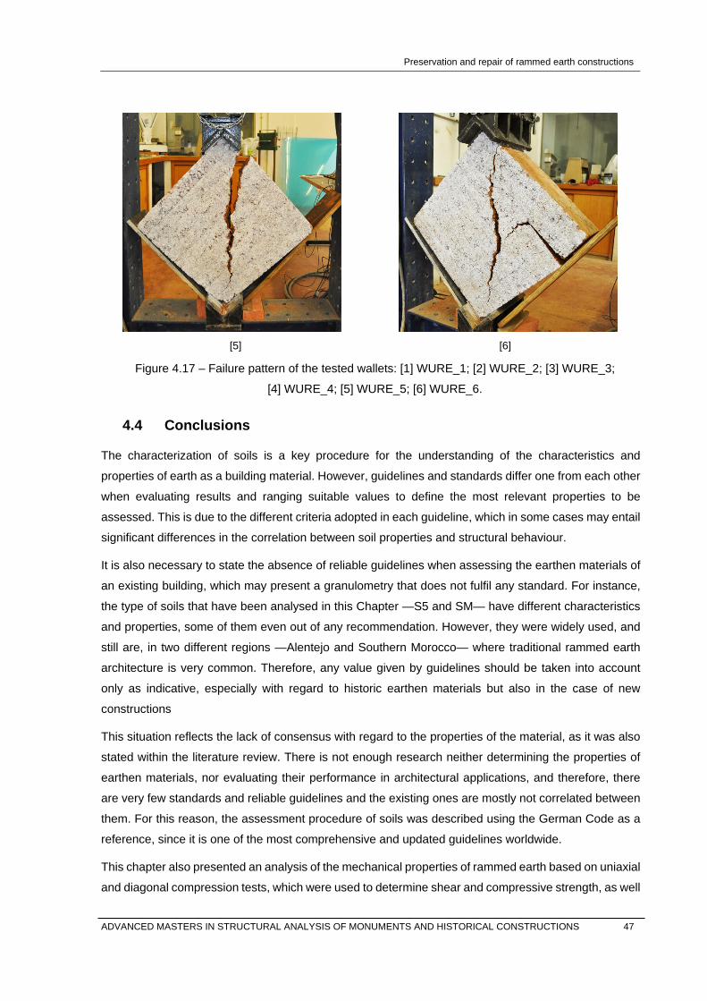
Preservation and repair of rammed earth constructions
[5] [6]
Figure 4.17 – Failure pattern of the tested wallets: [1] WURE_1; [2] WURE_2; [3] WURE_3;
[4] WURE_4; [5] WURE_5; [6] WURE_6.
4.4 Conclusions
The characterization of soils is a key procedure for the understanding of the characteristics and
properties of earth as a building material. However, guidelines and standards differ one from each other
when evaluating results and ranging suitable values to define the most relevant properties to be
assessed. This is due to the different criteria adopted in each guideline, which in some cases may entail
significant differences in the correlation between soil properties and structural behaviour.
It is also necessary to state the absence of reliable guidelines when assessing the earthen materials of
an existing building, which may present a granulometry that does not fulfil any standard. For instance,
the type of soils that have been analysed in this Chapter —S5 and SM— have different characteristics
and properties, some of them even out of any recommendation. However, they were widely used, and
still are, in two different regions —Alentejo and Southern Morocco— where traditional rammed earth
architecture is very common. Therefore, any value given by guidelines should be taken into account
only as indicative, especially with regard to historic earthen materials but also in the case of new
constructions
This situation reflects the lack of consensus with regard to the properties of the material, as it was also
stated within the literature review. There is not enough research neither determining the properties of
earthen materials, nor evaluating their performance in architectural applications, and therefore, there
are very few standards and reliable guidelines and the existing ones are mostly not correlated between
them. For this reason, the assessment procedure of soils was described using the German Code as a
reference, since it is one of the most comprehensive and updated guidelines worldwide.
This chapter also presented an analysis of the mechanical properties of rammed earth based on uniaxial
and diagonal compression tests, which were used to determine shear and compressive strength, as well
ADVANCED MASTERS IN STRUCTURAL ANALYSIS OF MONUMENTS AND HISTORICAL CONSTRUCTIONS 47
Preservation and repair of rammed earth constructions
as shear and elastic modulus. It was possible to state the high ductility of rammed earth under shear
loading, with a high post peak performance, which is a relevant property in the seismic assessment.
Due to this ductility, the development of secondary cracks was observed through the interface between
layers, which were initiated at the end of the test. Nevertheless, the seismic behaviour of rammed earth
constructions needs to be further studied by means of shear compression and out-of-plane tests on
walls and shaking table tests on scaled and full-scale models.
The Digital Image Correlation techniques were revealed as an interesting tool for the analysis of rammed
earth, since it allows the study of the deformation of the material and thus the development of cracks
before they appear at the naked eye, both before the maximum strength is reached and along the typical
long post-peak phase. However, deeper analysis with more detailed results are needed to accurately
define the crack pattern.
48 ADVANCED MASTERS IN STRUCTURAL ANALYSIS OF MONUMENTS AND HISTORICAL CONSTRUCTIONS
Preservation and repair of rammed earth constructions
5. REPAIR OF RAMMED EARTH BY MEANS OF GROUT INJECTION
5.1 Introduction
Any intervention concerning repair, strengthening or stabilization in any existing structure is a complex
process, with a series of requirements in terms conservation principles that are hard to fulfil completely.
This process is even more complex in earthen buildings due to the specific characteristics of the
material, and the repair of cracks due to earthquakes and weathering is an important issue to deal with.
The suitability of grout injection as a feasible technique in the repair of cracks will be assessed in this
Chapter. To this aim, the procedures and requirements of the technique will be introduced, and the
wallets that were previously tested will be repaired by means of the injection of two different grouts,
namely a mud grout and a lime-based grout. The main properties and characteristics of these grouts
will be also briefly described. The quality of the injection process will be assessed using sonic testing
both pre and post-grouting, and the effectiveness of the intervention will be determined within the test
of the repaired wallets under diagonal compression. The obtained results will be compared with those
obtained in the experimental program that was carried out by Silva (2013) in similar conditions.
5.2 Grout injection of cracks
Usually, repair and strengthening methods of earthen buildings are based on the addition of structural
elements that increase the overall stability of the structure, for instance by adding timber reinforcements
(Yamín Lacouture, et al., 2007). Some of these methods are usually simple and economic, and the
effectiveness of the interventions is high. However, the alteration that they introduce to the building may
not be compatible with the recommendations and criteria established in international charters and
document, and for this reason, they are generally not suitable for historic constructions.
Grout injection is a repair/strengthening solution often used in masonry structures, which has been
proven to be highly efficient in terms of structural behaviour improvement (Valluzzi, et al., 2002).
Generally speaking, this technique consists on the injection of a fluid mortar through the cracks or holes
previously drilled, in order to fill cracks, existing cavities and internal and communicant net voids. This
improves the continuity of the material and partially recovers the original wall integrity without altering
their morphology. However, it is important to note that it is a non-reversible technique and may cause
durability problems if the used materials are not compatible with the existing ones (Silva, et al., 2014).
5.2.1 Grout properties
Grouts are composed by three basic elements: binder, aggregate and dispersant. Binders can be
distinguished between organic —polymers— and mineral materials —mainly clay, lime and cement.
Aggregates are usually fine particles, while water is used as dispersant. Occasionally, additional
elements such as synthetic pozzolanas can be added, which improve the behaviour of the grout
(Toumbakari, 2002). ADVANCED MASTERS IN STRUCTURAL ANALYSIS OF MONUMENTS AND HISTORICAL CONSTRUCTIONS 49

Preservation and repair of rammed earth constructions
According to Toumbakari (2002), the mechanical properties of the grout hardly influence the final
compressive strength of injected masonry, and even in the case of stiffer grouts, damages may occur
due to mechanical incompatibility. On the other hand, important requirements of the injection are the
bonding between grout and the substratum, and the complete filling of the voids, which depends on the
penetrability of the grout. Therefore, within the formulation process of the grout, it is preferable to focus
on rheology, tensile strength and adhesion instead of on compressive strength.
The penetrability requirements include stability, fluidity, and penetrability, which mainly depend on the
water-binder ratio (Toumbakari, 2002), and on the physical and chemical properties of the grout. Stability
is the capacity of the grout to keep homogeneous up to the hardening, and it is related to excessive
bleeding and segregation. It can be measured experimentally through the standard ASTM 940 (ASTM,
2010), and can be improved by correctly defining the composition of the grout and controlling the mixing
procedure.
Fluidity is the capacity of a grout to keep fluid enough to flow through the substratum of the injected
element. It depends mainly on the content of water and on the PSD of the grout, as well as on its nature,
shape and specific surface of its particles. It is measured in terms of the time needed for the grout to
flow through a standard recipient, which is generally the Marsh funnel Viscometer (Figure 5.1), e.g. in
ASTM C 939 (ASTM, 2010).
Figure 5.1 – Marsh cone used in the flow time tests carried out at UMinho (dimensions in mm).
Finally, penetrability consists in the capacity of the grout of penetrating through the substratum, which
depends on the PSD of the aggregate and on viscosity, which in the case of mineral grouts mainly
depends on the water content, as well as on the water retention capacity of the grout flowing through
the substratum. Penetrability can be evaluated within the ASTM C943 (ASTM, 2010) using standardized
sand column test (Figure 5.2). Regarding the width of the cracks to be injected, only those with a width
larger than three times the maximum particle size of the grout are injectable (Miltiadou, 1990).
60
8
155
280
50 ADVANCED MASTERS IN STRUCTURAL ANALYSIS OF MONUMENTS AND HISTORICAL CONSTRUCTIONS

Preservation and repair of rammed earth constructions
Figure 5.2 – Sand column to test the penetrability of a grout.
All these parameters can be defined through the formulation of a grout as a balance between the basic
elements. Within the process, it is necessary to take into account the dependence between the
properties of the grout, but also between them and the injected element. For instance with regard of the
porosity of the material, which may have an important influence on properties such as penetrability.
Furthermore, other factors such as the application and mixing procedures are also relevant. The whole
process of formulation and injection of the grout is, then, very complex, as detailed in Silva (2013).
5.3 Grout injection of rammed earth specimens
Grout injection is mostly used in ancient masonry walls, which are very heterogeneous and may have
multiple leaves and different textures, from rubble to regularly brick-bonded masonry. These structures
may present interior cavities that are not visible from outside, and it is necessary to inject the grout
through drilled holes. With regard to earthen materials, the principles of the technique are similar, but
the requirements of the grouts may change. According to Vargas, et al, (2008), the repair of adobe
masonry walls by means of unmodified mud grouts is proved to be more effective than using modified
ones, probably because of a compatibility issue.
In the case of rammed earth walls, the general requirements of the technique are similar to those
applicable to adobe masonry walls (GCI, 2007). However, there are some specific issues to be
considered in the case of earthen materials. The massive and compact nature of the material makes
grout injection only suitable for external cracks, passing through cracks, and/or for the interface between
blocks, which may be very thin. For this reason, grouts with high penetrability are required. Furthermore,
it is important to consider that dry earthen materials have a high absorbing capacity, therefore it is
required that the grout achieves higher fluidity with a minimum content of water, maintaining adequate
fluidity and penetrability during the full injection process. In order to improve this requirement,
deflocculants may be added to the grout (Silva, 2013).
Based on the mentioned criteria, an experimental program was carried out in Silva (2013) in order
understand the behaviour of unmodified mud grouts and the influence of all the requirements above
described. Within the testing campaign, commercial kaolinite and natural clay two different types of clays
were used, and tested grouts included different proportions, of clay, limestone powder, and sodium
hexametaphosphate —HMP— as deflocculant for clays. Regardless of the type of clay, this work proved
ADVANCED MASTERS IN STRUCTURAL ANALYSIS OF MONUMENTS AND HISTORICAL CONSTRUCTIONS 51

Preservation and repair of rammed earth constructions
that the colloid behaviour of clays limits the rheology of the mud grout. Therefore, the addition of
deflocculant and the adjustment of the clay content greatly improves the rheological behaviour of the
grout. Taking this conclusions into consideration, two unmodified mud grouts resulting from this study
were injected in rammed earth wallets in order to assess their adhesion capacity. The results of this test
will be compared with those obtained within the present work, in which two grouts with different
formulation will be used to inject the six wallets tested as described in Section 4.3.3.
5.3.1 Characterization and preparation of grouts
The aggregates of the grouts tested in Silva (2013) —namely G1 and G2— were obtained from soil S5.
Soil was sieved up through the ASTM sieve #80 —up to 0.18 mm. Others components within the
formulation of the grout were limestone powder and HMP (Figure 5.3). The volumetric solid fraction —
ϕv— in both grouts was 55%, and the HMP ratio with respect to the total mass of the grout was 0.022
g/g. The ratio between water and solids —W/S— is 0.3 in both grouts, while the proportion between
sieved soil and lime varied (Table 5.1).
[1] [2]
Figure 5.3 – Preparation of the grout G3: [1] components of the grout before being mixed; [2] mixture
with an electrical mixer.
Table 5.1 – Composition of the mud grouts G1 and G2 (Silva, 2013).
Grout 80#S5 Limestone powder W/S HMP
[%] [%] [-] [g/g]
G1 40 60 0.30 0.022
G2 50 50 0.30 0.022
With regard to the grouts tested in the present work, the grout G3 has the same composition as that of
grout G1 (Table 5.1). Alternatively to the unmodified mud grouts, the grout G4 is a commercial grout
composed mainly with natural hydraulic lime, where the ratio W/S is of about 0.33 (Table 5.2). The
natural hydraulic lime is certified as moderate hydraulic —type NHL 3.5—, it is partially hydrated, and it
52 ADVANCED MASTERS IN STRUCTURAL ANALYSIS OF MONUMENTS AND HISTORICAL CONSTRUCTIONS

Preservation and repair of rammed earth constructions
is obtained from a limestone that contain between 15 and 20% of clay and other impurities. This type of
grouts have the main advantages of both hydrated and hydraulic limes (Biçer & Rainer, 2013), e.g. faster
setting and compatibility, and it is also proved that its fluidity stays constant during the first hour and
then decreases rapidly (Keersmaekers, et al., 2006), which is a convenient property.
Table 5.2 – Composition of the grout G4 used to repair the rammed earth wallets.
Grout Natural hydraulic lime W/B
[%] [-]
G4 100 0.33
The fluidity of the grouts is assessed by means of the standard ASTM C 939 (ASTM, 2010), which
measures the flow time of 1 dm3 of grout through a Marsh cone with a nozzle-diameter of 8 mm (Figure
5.4).The fresh mixture was used to mould 6 specimens —3 with G3 and 3 of G4— of 40x40x160 mm3
that were tested under bending and compression after 28 days (Figure 5.5) within the procedure given
by the standard UNE-EN 1015-11 (AENOR, 2000). The properties of the grouts G3 and G4 are
compared with the grouts G1 and G2 in Table 5.3.
Table 5.3 – Properties of the grouts G1, G2 (Silva, 2013), G3 and G4.
Grout Flow time fb fc
[s] [MPa] [MPa]
G1 36.51 0.92 2.44
G2 37.01 1.15 3.47
G3 42.32 1.41 2.06
G4 43.92 3.37 5.26 1 Average flow time for 1dm3 of water of 10.5 s at 23.3 ºC. 2 Average flow time for 1dm3 of water of 13.1 s at 22.0 ºC.
[1] [2]
Figure 5.4 – Characterization of grouts: [1] measurement of the flow time of the grout G3 through a
Marsh cone; [2] moulding process for the preparation of the specimens.
ADVANCED MASTERS IN STRUCTURAL ANALYSIS OF MONUMENTS AND HISTORICAL CONSTRUCTIONS 53

Preservation and repair of rammed earth constructions
[1] [2]
Figure 5.5 – Testing of the grout specimens: [1] under bending; [2] under compression.
The grout G4 presented the highest value of flow time despite the higher water content. However, the
difference between G4 and G3 is marginal, meaning that they have similar fluidity. On the other hand,
the flow time of grout G3 is higher than that of grout G1 in spite of their same composition. This difference
may be a consequence of different testing conditions, namely regarding the temperature of the grout,
and of differences that may be intrinsic of the original soil, which was sieved at different dates.
With regard to the mechanical strength of the grout, the highest values of compressive and bending
strength correspond to the grout G4 as expected. Among the unmodified grouts, they are on the same
order of magnitude even if the results are slightly contradictory between the two testing campaigns,
which may be due to slightly differences in the sieved soil.
The compressive strength of the rammed earth cylinders tested in Section 4.3.1 was of about 1.50 MPa,
which is significantly lower than the strength values of the grouts. However, as previously referred, the
compressive strength of the grout does not have a great influence in the strengthening of the infill
material (Toumbakari, 2002). On the contrary, tests on three-leaf masonry have demonstrated that the
strength enhancement of the masonry is proportional to the tensile strength of the grout, since bond
properties depend on its tensile strength (Vintzileou, 2011).
5.3.2 Injection of the rammed earth wallets
The repair process was performed first by sealing cracks with earth mortar prepared with soil S5 sieved
up to the fine gravels —sieve #4 for a particle size below 4.75 mm (Figure 5.6). Injection tubes of 6 mm
of diameter were simultaneously placed, first in the intersection of cracks and then all along the cracks.
In the case of horizontal cracks, additional tubes were installed in the other side of the wallets to facilitate
the evacuation of air, but they were not used for injection. Before injecting the grouts, 100 ml water was
injected in order to remove the finest particles of the inner surfaces. This water improves the penetrability
of the grouts by reducing the water absorption by the rammed earth.
54 ADVANCED MASTERS IN STRUCTURAL ANALYSIS OF MONUMENTS AND HISTORICAL CONSTRUCTIONS

Preservation and repair of rammed earth constructions
The grout was injected from the bottom up using injection tubes (Figure 5.6), and once the grout reached
the level of the next tube, making it leak, the tube being injected was sealed. The process continued
with the injection of the leaking tube, and so on. The conditions of the injection procedure are detailed
in Table 5.4, where the type of grout and the total volume of injected grout —Vgi— is presented for each
wallet. This volume depends on the state of the wallets after being tested.
[1] [2]
Figure 5.6 – Injection of the rammed earth wallets: [1] sealing of the cracks and placement of tubes;
[2] injection of the grout with a syringe.
Table 5.4 – Conditions of the injection of the wallets.
Specimen Injected grout Vgi
[-] [l]
WUREi_1 G4 2.2
WUREi_2 G3 1.6
WUREi_3 G4 3.1
WUREi_4 G4 1.2
WUREi_5 G3 1.3
WUREi_6 G3 1.4
The grouts were injected manually using a syringe, so the pressure used for the injection was not
measured. In any case, this pressure can be considered as low, even if the grout G4 needed a slightly
higher pressure than the grout G3 to be injected. This difference is related to the penetrability properties
of both grouts. For instance, grout G3 is expected to have a better water retention capacity than G4,
which is provided by its very high content in very fine particles, namely clay.
It is important to note that the injection of the horizontal cracks was not possible in some cases, either
because of the difficulty in evacuating the air, or because the crack was too thin. In any of these cases,
the injection was not optimal, which is expected to influence the mechanical behaviour of the wallet.
ADVANCED MASTERS IN STRUCTURAL ANALYSIS OF MONUMENTS AND HISTORICAL CONSTRUCTIONS 55

Preservation and repair of rammed earth constructions
5.3.3 Diagonal compression tests of rammed earth wallets
After 28 days of drying/curing process, the six injected wallets were tested under diagonal compression
following a similar procedure as that described in Section 4.3.3. The results of the wallets that were
injected with the grout G3 are presented in Table 5.5, as well as the comparison with the values that
were obtained before the injection. In the same way, the results obtained when using the grout G4 are
presented and compared in Table 5.6.
Table 5.5 – Results of the wallets repaired with the grout G3.
Injection with grout G3
fSG fSI fSG / fSI GG Gi GG / GI γG γI ∆γ
[MPa] [MPa] [%] [MPa] [MPa] [%] [mm/m] [mm/m] [%]
WUREi_1 0.122 0.048 39 1056 148 14 0.012 0.040 336
WUREi_3 0.168 0.076 45 632 130 20 0.056 0.159 281
WUREi_4 0.131 0.066 50 1068 86 8 0.032 0.142 437
Average 0.140 0.063 44 919 121 14 0.034 0.114 351
CoV [%] 14 18 10 22 21 36 53 46 18
Table 5.6 – Results of the wallets repaired with the grout G4.
Injection with grout G4
fSG fSI fSG / fSI GG Gi GG / GI γG γ I ∆γ
[MPa] [MPa] [%] [MPa] [MPa] [%] [mm/m] [mm/m] [%]
WUREi_2 0.1606 0.070 44 1356 99 7 0.047 0.172 367
WUREi_5 0.1278 0.066 51 460 22 4 0.059 0.707 1201
WUREi_6 0.1156 0.068 58 71* 33 46* -0.105* 0.468* -443*
Average 0.135 0.068 51 908 51 6 0.053 0.439 784
CoV [%] 14 2 11 50 66 21 11 60 53 * Outlier values not considered.
The wallets injected with the grout G3 showed shear strength values —fSI— in the range of 0.048 and
0.076 MPa with an average value of 0.063 MPa, while those wallets injected with G4 showed values
between 0.066 and 0.070 MPa, with an average value of 0.068 MPa. The average in terms of recovery
of the initial capacity —fGI/fSI— is 44% with the grout G3 and 51% with the grout G4. In the case of the
grouts G1 and G2, the shear strength of the wallets after the repair was 0.10 MPa and 0.08 MPa
respectively, while the average recovery rate was of about 66% and 59%. These values are slightly
higher than the ones obtained by the current tests, but they are still on the same order of magnitude. It
can be concluded, as previously stated, that the compressive strength of the grout does not have a
remarkable influence in the mechanical behaviour of injected rammed earth walls. However, the
achieved percentages in all cases are far from the total recovery, which suggests that the influence of
the quality of the grout, at this point, is less important, and the mechanical behaviour of the wallet is
56 ADVANCED MASTERS IN STRUCTURAL ANALYSIS OF MONUMENTS AND HISTORICAL CONSTRUCTIONS

Preservation and repair of rammed earth constructions
more influenced by other factors, as it will be discussed subsequently. In this situation, then, the
differences in terms of tensile strength between grouts seem not to have major a influence either.
With regard to the shear modulus —GI— values are in the range of 86 and 146 MPa when the grout G3
was used, and between 21 and 99 MPa for the grout G4, with average values of about 121 and 51 MPa.
Average percentages of recovery —GG/GI— are around 14% and 6% respectively. All these results are
also on the same range of values as the ones obtained with the grouts G1 and G2. These results can
be considered as valid, but they showed higher percentages of variability than those obtained for the
shear strength. This variability also occurs in the values of shear modulus obtained in Silva (2013), and
it may be related with the testing procedure itself, since the displacement transducers were used only
in one side. In this type of test, wallets may also rotate in the perpendicular direction of the specimen,
and these displacements are taken into account placing the transducers on both sides. With regard to
the outlier value that was obtained in the WURE_6, it was not considered in the evaluation of the results.
In the comparison between the percentages of recovery, it is relevant to note that the values obtained
for the shear modulus are significantly lower than those obtained for the shear strength. This situation
occurs probably due to the irreversible loss of the interlocking effect of the coarse aggregates during the
first test, in which the wallets were loaded until failure. Furthermore, during the first loading process, as
described in Section 4.3.3, the micro-structure of the material was progressively broken up and micro-
cracking occurred between the binder, namely the clay, and the aggregate.
After the injection of the cracks, the continuity of the wallet is partially recovered, but not the overall
cohesion of the material. The binding capacity of clays is partially lost, and the shear strength of the
material is mainly given by friction between coarse aggregates. The elastic phase is, then, very short
and it is due to the initial strength given by the grout and the reduced cohesion of the material. This is
reflected in the resultant stress-strain curves, which are very soft and do not present any yield point
(Figure 5.7). The stress-strain curves corresponding to all tests can be found in Annex A.
[1] [2]
Figure 5.7 – Stress-strain curves before and after injection: [1] WUREi_1; [2] WUREi_3
0,00
0,02
0,04
0,06
0,08
0,10
0,12
0,14
0,16
0,18
0 5 10 15
Stre
ss [M
Pa]
Strain [mm/m]
0,00
0,02
0,04
0,06
0,08
0,10
0,12
0,14
0,16
0,18
0 5 10 15
Stre
ss [M
Pa]
Strain [mm/m]
ADVANCED MASTERS IN STRUCTURAL ANALYSIS OF MONUMENTS AND HISTORICAL CONSTRUCTIONS 57
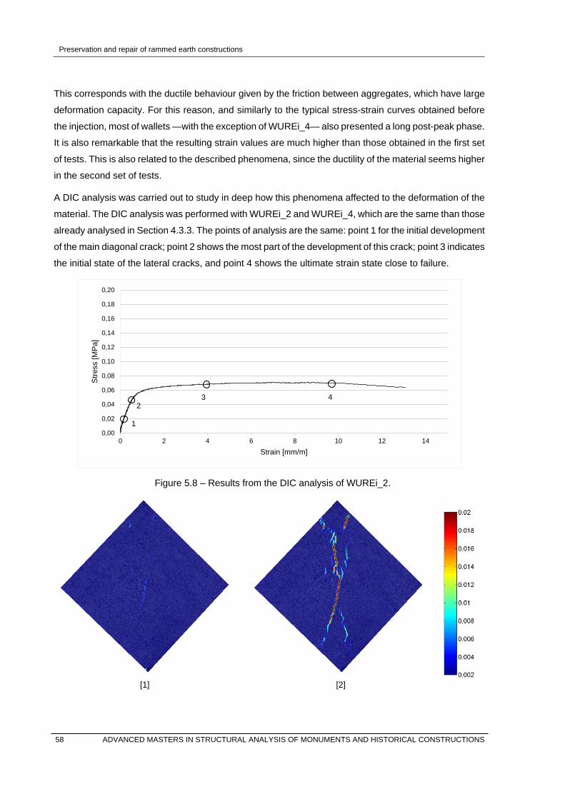
Preservation and repair of rammed earth constructions
This corresponds with the ductile behaviour given by the friction between aggregates, which have large
deformation capacity. For this reason, and similarly to the typical stress-strain curves obtained before
the injection, most of wallets —with the exception of WUREi_4— also presented a long post-peak phase.
It is also remarkable that the resulting strain values are much higher than those obtained in the first set
of tests. This is also related to the described phenomena, since the ductility of the material seems higher
in the second set of tests.
A DIC analysis was carried out to study in deep how this phenomena affected to the deformation of the
material. The DIC analysis was performed with WUREi_2 and WUREi_4, which are the same than those
already analysed in Section 4.3.3. The points of analysis are the same: point 1 for the initial development
of the main diagonal crack; point 2 shows the most part of the development of this crack; point 3 indicates
the initial state of the lateral cracks, and point 4 shows the ultimate strain state close to failure.
Figure 5.8 – Results from the DIC analysis of WUREi_2.
[1] [2]
0,00
0,02
0,04
0,06
0,08
0,10
0,12
0,14
0,16
0,18
0,20
0 2 4 6 8 10 12 14
Stre
ss [M
Pa]
Strain [mm/m]
1
2 3 4
58 ADVANCED MASTERS IN STRUCTURAL ANALYSIS OF MONUMENTS AND HISTORICAL CONSTRUCTIONS

Preservation and repair of rammed earth constructions
[3] [4]
Figure 5.9 – Resultant maximum principal strains from the DIC analysis of WUREi_2.
Figure 5.10 – Results from the DIC analysis of WUREi_4.
[1] [2]
0,00
0,02
0,04
0,06
0,08
0,10
0,12
0,14
0,16
0,18
0,20
0 2 4 6 8 10 12 14
Stre
ss [M
Pa]
Strain [mm/m]
1 2 3 4
ADVANCED MASTERS IN STRUCTURAL ANALYSIS OF MONUMENTS AND HISTORICAL CONSTRUCTIONS 59

Preservation and repair of rammed earth constructions
[3] [4]
Figure 5.11 – Resultant maximum principal strains from the DIC analysis of WUREi_4.
As already discussed, stress-strain curves were softer and lower than those obtained with the non-
injected wallets (Figure 4.8 and 4.10). Related to this, the development of the diagonal crack was
progressive, unlike in the non-injected wallet, in which it was suddenly and rapidly developed. The lower
value of the shear modulus also influenced in the development of the crack, which occurs with lower
values of stress with respect to the shear strength. In WUREi_2 the diagonal crack initiated at the 28%
of the ultimate shear strength, while in WUREi_4 this occurred at the 64% (Figure 5.9 and Figure 5.11).
In both cases, the DIC analysis showed that the development of the main crack occurred through the
interface between the grout and the rammed earth, which is the weakest point of the material. It was
through the interface where the deformations were concentrated, and this is the reason why the amount
of crushing of the material was lower around the crack, and near the edges. With regard to the lateral
cracks, in both cases were existing cracks that were reopened. In the case of the WUREi_2, these
cracks appeared at the very end of the test, while in WUREi_4 they appeared earlier. This is also related
to the weaker interface that was stated in the previous test.
[1] [2]
60 ADVANCED MASTERS IN STRUCTURAL ANALYSIS OF MONUMENTS AND HISTORICAL CONSTRUCTIONS

Preservation and repair of rammed earth constructions
[3] [4]
[5] [6]
Figure 5.12 – Failure pattern of the tested wallets: [1] WUREi_1; [2] WUREi_2; [3] WUREi_3;
[4] WUREi_4; [5] WUREi_5; [6] WUREi_6
With regard to the failure pattern of the specimens, failure occurred similarly as in the first set of tests,
which was due to the development of a primary diagonal crack. This crack is initiated at the middle of
the specimens and is developed through the interface between the rammed earth and the grout material.
In all cases and with both types of grout, failure occurred in the rammed earth, which confirms the good
adhesion of the grout. This can be observed in the surface of the interface after cracking, where the
grout is not visible (Figure 5.18).
In the case of the WUREi_3, only the main diagonal crack was developed before failure, while in other
specimens some secondary cracks were also developed through the interface between compacted
layers, always repaired cracks. In the case of WUREi_5 and WURE_6, failure was due also to one of
the horizontal cracks that was repaired (Figure 5.12). This is due to the difficulties of the injection
process, which derives in problems of continuity, as was reported within Section 5.3.2.
ADVANCED MASTERS IN STRUCTURAL ANALYSIS OF MONUMENTS AND HISTORICAL CONSTRUCTIONS 61

Preservation and repair of rammed earth constructions
[1] [2]
Figure 5.13 – Adhesion between grout and rammed earth: [1] WUREi_3; [2] WUREi_6;
It is important to note that some of these secondary cracks already appeared in the first test, and
therefore they were repaired, but some of them are new. The new secondary cracks were probably
initiated at the very end of the first test, but they were not fully developed before failure occurred, and
therefore they were not visible and, thus, not repaired. During the second test, since they are a weak
point of the material, they continued being developed until complete failure. An analysis by means of
Digital Image Correlation can also give critical information about the initial phase of the cracks.
All the obtained results —low to percentage of recovery, very low shear modulus and typical failure
pattern— are correlated with the same phenomena. This is, progressive loss of cohesion during the first
test, and the performance decrease of the interlocking mechanisms of the coarse particles. Since both
processes are irreversible and they are only improved near the injected part, the overall decay of the
material was not recovered for the second set of tests. Furthermore, failure occurred mainly in rammed
earth close to the interface between grout and rammed earth.
Regarding the equilibrium water content, the percentages are slightly lower than the values obtained
before the injection, but variations are very low. However, the influence of the equilibrium water content
in the injected wallets may be lower in comparison with the above described phenomena (Table 5.7).
62 ADVANCED MASTERS IN STRUCTURAL ANALYSIS OF MONUMENTS AND HISTORICAL CONSTRUCTIONS
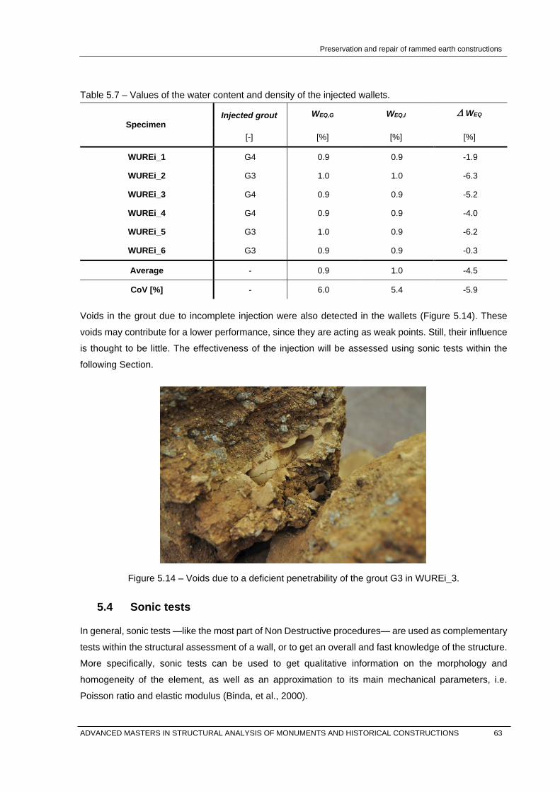
Preservation and repair of rammed earth constructions
Table 5.7 – Values of the water content and density of the injected wallets.
Specimen Injected grout WEQ,G WEQ,I ∆ WEQ
[-] [%] [%] [%]
WUREi_1 G4 0.9 0.9 -1.9
WUREi_2 G3 1.0 1.0 -6.3
WUREi_3 G4 0.9 0.9 -5.2
WUREi_4 G4 0.9 0.9 -4.0
WUREi_5 G3 1.0 0.9 -6.2
WUREi_6 G3 0.9 0.9 -0.3
Average - 0.9 1.0 -4.5
CoV [%] - 6.0 5.4 -5.9
Voids in the grout due to incomplete injection were also detected in the wallets (Figure 5.14). These
voids may contribute for a lower performance, since they are acting as weak points. Still, their influence
is thought to be little. The effectiveness of the injection will be assessed using sonic tests within the
following Section.
Figure 5.14 – Voids due to a deficient penetrability of the grout G3 in WUREi_3.
5.4 Sonic tests
In general, sonic tests —like the most part of Non Destructive procedures— are used as complementary
tests within the structural assessment of a wall, or to get an overall and fast knowledge of the structure.
More specifically, sonic tests can be used to get qualitative information on the morphology and
homogeneity of the element, as well as an approximation to its main mechanical parameters, i.e.
Poisson ratio and elastic modulus (Binda, et al., 2000).
ADVANCED MASTERS IN STRUCTURAL ANALYSIS OF MONUMENTS AND HISTORICAL CONSTRUCTIONS 63

Preservation and repair of rammed earth constructions
Within the present work, sonic tests are used to evaluate the effectiveness of the repair procedure of
the tested rammed earth wallets, measuring the homogeneity of the material before and after the
injection of the grout.
5.4.1 Fundamentals of sonic test
Sonic tests are Non Destructive Tests —NDT— that consist in transmitting stress waves within the
frequency range of acoustic waves —20 Hz to 20 kHz—, generated by an instrumented hammer, and
in measuring their travel time —and therefore the velocity— by means of accelerometers. The impact
on the surface of any material transmits different types of waves, which are classified as planar waves
in the axial direction —P and S-waves—, and surface waves in the radial direction —R-waves, also
including P and S-waves (Figure 5.15).
* Numbers indicate relative velocities.
[1] [2]
Figure 5.15 – Transmission of waves and relative velocities [1], and recorded signal [2] (Mendes, 2009)
The velocity of these waves is related to the elastic coefficients of the material, as well as its internal
structure and density. When performing a sonic test, only P and R-waves are relevant, and the
identification of both of them is represented in Figure 5.15. The point 1 marks the arrival of the P-waves,
which are faster but have a lower amplitude. In the point 2 it is possible to see an increase of the signal
amplitude, which means the arrival of the R-waves. These waves are slower but have a higher
amplitude, therefore they can be identified with their first peak, represented by the point 3. The set of
instruments used to measure and analyse the signal consists of an instrumental hammer for the initial
pulse; a piezoelectric accelerometer that measures the generated signal; an acquisition unit from
National Instruments, and the software for the visualization and analysis of the results (Figure 5.16).
The analysis of the signal, through the LabVIEW software, consists on measuring the time between the
initial impact of the hammer and the reception of each type of wave (Figure 5.16). Since the distance
between the point of impact and the point of reception is known, the velocity of waves can be calculated,
which is a qualitative indicator of the homogeneity of the material.
1 2
3
64 ADVANCED MASTERS IN STRUCTURAL ANALYSIS OF MONUMENTS AND HISTORICAL CONSTRUCTIONS

Preservation and repair of rammed earth constructions
[1] [2]
Figure 5.16 – [1] Set of instruments used in sonic tests; [2] direct sonic test. Overlapping of the
signal of the hammer and of the accelerometer.
As previously mentioned, the propagation of these waves is related to the elastic properties of the
material, and therefore it is possible to calculate the dynamic modulus of elasticity —Ed—, which is the
elastic modulus under vibratory conditions, and the Poisson ratio —ν— of an isotropic elastic medium
(Equation 5.1, Equation 4.2, Equation 4.3).
( )( )( )
11 1 2
dP
EV
υρ υ υ
−=
+ − [m/s] (Equation 5.1)
( )0.87 1.12 1
1 1 1d
RE
V υυ ρ υ
+=
+ + [m/s] (Equation 5.2)
( )
( )( )
( )
2
22 1 11 2 0.87 1.12
P
R
VV
υ υυ υ
− +=
− + [-] (Equation 5.3)
Where:
VP is the velocity of the P-waves.
VR is the velocity of the R-waves.
Ed is the dynamic modulus of elasticity measured in GPa.
ρ is the density of the material in kg/m3.
ν is the Poisson ratio.
Since the mechanical parameters of the material are measured indirectly with this method, the dynamic
elastic modulus is slightly different —generally higher— than the static elastic modulus. This is due the
presence of fractures and cavities, and therefore higher heterogeneity —or decay— of the material
entails higher deviations between both values.
ADVANCED MASTERS IN STRUCTURAL ANALYSIS OF MONUMENTS AND HISTORICAL CONSTRUCTIONS 65

Preservation and repair of rammed earth constructions
However, the factors affecting the correlation between Ed and E are still not fully understood, even if
several attempts have been made to establish a satisfactory correlation in concrete (Popovics, et al.,
2008). The Equation 4.4 is an empirical relationship for concrete’s elastic moduli that was accepted as
part of the British Standard (BSI, 1986).
1.25 19dE E= − [GPa] (Equation 5.4)
All these equations are valid only for isotropic materials and they are not accurate neither for masonry
nor for earthen materials. In these cases, as heterogeneous materials, the correlation between sonic
velocities and mechanical parameters exists, but it can be established only empirically with experimental
data. The number of measurements must be high to be statistically significant, and for this reason, they
could not be carried out within this work.
5.4.2 Sonic testing procedure
Direct tests were performed along the length of the wallets, from edge to edge, in 3 points of
measurement with a distance of 55 cm. Indirect tests were performed in both sides using a grid of 3 by
3 points with a distance between points of measurement of about 35 cm (Figure 5.18). The total number
of points was 15 for each panel, with 15 measurements per point. From each point, the 6 most
representative signals were evaluated, and only those with a coefficient of variation lower than 20%
were considered.
Figure 5.17 – Testing grid for the indirect measurements in both sides of the panel.
As previously stated, different types of wave are considered depending on the type of sonic test. The
measurement of the P-waves is direct, since these waves are the first to be detected by the transducer.
However, the point 2 in indirect tests cannot be accurately determined, since the signal acquisition is
affected by the ambient noise and the vibration of the whole wallet when hammering. In this case, the
interpretation of the signal is more difficult (Figure 5.19).
66 ADVANCED MASTERS IN STRUCTURAL ANALYSIS OF MONUMENTS AND HISTORICAL CONSTRUCTIONS

Preservation and repair of rammed earth constructions
Figure 5.18 – Indirect sonic test. Overlapping of the signal of the hammer and of the accelerometer.
In order to eliminate this noise, a high-pass filter was applied to the signals of the indirect tests. However,
the resultant signal was not valid because noise affects to a wide range of frequencies within the
frequency domain —lower and higher frequencies—, and therefore the waves produced by hammer
were also filtered. Finally, it was decided to measure both P and R-waves. In order to minimize the errors
in the measurements caused by the mentioned phenomena, the R-wave velocity —VR— was considered
as valid only when the relation with respect to the P-wave velocity —VP— was of about 0.56 (Figure
5.20). This coefficient was empirically established, and relates the velocity of both types of waves in
regular conditions and in isotropic materials (Mendes, 2009). Therefore, it is expectable that the resultant
coefficient varies due to the anisotropic nature of rammed earth. In this case, in order to assure the
consistence of the results, only the 6 measurements with lower coefficient of variation among the 15 will
be considered.
Figure 5.19 – Indirect sonic test. Overlapping of the signal of the hammer and of the accelerometer.
5.4.3 Direct sonic tests
For the direct test, the assessment of the injection quality is made in qualitative terms through the
comparison between the average velocity of the P-waves before and after the injection. The distance
between the measured points is 0.55 cm, which corresponds to the total width of the specimen. The
measurement points were located at a height of 10 cm, 27.5 cm —mid-height—, and 45 cm from the
bottom part of the wallets. The average results are summarized in Figure 5.21 and Table 5.8.
ADVANCED MASTERS IN STRUCTURAL ANALYSIS OF MONUMENTS AND HISTORICAL CONSTRUCTIONS 67

Preservation and repair of rammed earth constructions
Figure 5.20 – Average velocities of the direct sonic tests in all specimens.
Table 5.8 – Results of the direct sonic tests before and after the grouting.
Specimen Injected grout VPG VPI ∆VP
[-] [m/s] [m/s] [%]
WUREi_1 G4 2109.0 1728.9 -18
WUREi_2 G3 2505.0 2710.0 -15
WUREi_3 G4 2453.9 1668.4 -32
WUREi_4 G4 2089.4 2590.3 -4
WUREi_5 G3 2191.0 1411.5 -35
WUREi_6 G3 2710.0 2501.3 -7
Average - 2343.1 2101.7 -18.5
CoV [%] - 10 24 -63
Direct sonic tests on non-injected wallets resulted on average values of 2468.7 m/s. Compared with
other earthen materials, this value is expected to be high due the compact nature of rammed earth.
However, no specific studies in earthen materials were found, so it is not possible to compare these
results in detail. In the comparison with masonry structures, this value corresponds to mid-good quality
masonry (Berra, et al., 1992).
The measured velocities after the injection were on average 18% lower between sets of tests, which
confirms the loss of homogeneity of the material. This could be considered as expectable, since rammed
earth is a highly compacted material and within the process of testing under compression, it partially lost
its cohesion, as discussed in Section 5.3.3. The use of different type of grouts did not affect the results,
and with both grouts G3 and G4 the results were very similar (Figure 5.22). With this regard, more
detailed results can be found in Annex B.
0
500
1000
1500
2000
2500
3000
WURE_1 WURE_2 WURE_3 WURE_4 WURE_5 WURE_6
Velo
city
[m/s
]
Vp before injection Vp after injectionAvg Vp before injection Avg Vp after injection
68 ADVANCED MASTERS IN STRUCTURAL ANALYSIS OF MONUMENTS AND HISTORICAL CONSTRUCTIONS

Preservation and repair of rammed earth constructions
[1] [2]
Figure 5.21 – Average results of the direct sonic tests. [a] WURE_1; [b] WURE_2.
From the obtained results, it is important to note that the coefficient of variation of the velocities
measured before the injection is of about 10%, while the variability of those results obtained after the
injection is of about 24%. This variability is due to the different conditions of the injection —amount of
grout and number of voids—, and to the different level of decay of the rammed earth material. This can
be verified with the analysis of the results obtained in each point of measurement (Figure 5.22), which
allow a better identification of those points in which the injection was not satisfactory.
5.4.4 Indirect sonic tests
For the indirect tests, measurements were made in both sides of the wallet through a squared grid of
3x3 points. These points were located at 10 cm from the bottom and left side, 25.7 cm, and 45 cm, with
a distance between measurements of 35 cm. The average results are represented in Figure 5.23 and
Figure 5.24, with a breakdown between horizontal and vertical measurements.
As discussed in Section 5.4.2, the measurement of the signal presented some errors caused by the
vibration of the specimen when hammering. These errors were minimized considering the factor that
relates the velocity of both R and P-waves, and only those values that presented less variability were
considered. This factor is 0.56 in regular conditions and in isotropic materials, and any deviation from
this reference value means that the material presents alterations or discontinuities. Another indicator of
the reliability of the results is the error within these measurements —and therefore the validity of the
data—, which can be evaluated with the coefficient of determination —R2— of the simple linear
regression (Figure 5.23 and Figure 5.24).
0
500
1.000
1.500
2.000
2.500
3.000
10 27,5 45
Velo
city
[m/s
]
Heigth [cm]
0
500
1.000
1.500
2.000
2.500
3.000
10 27,5 45
Velo
city
[m/s
]
Heigth [cm]
ADVANCED MASTERS IN STRUCTURAL ANALYSIS OF MONUMENTS AND HISTORICAL CONSTRUCTIONS 69

Preservation and repair of rammed earth constructions
Figure 5.22 – Average results of the horizontal measurements with indirect sonic tests.
Figure 5.23 – Average results of the vertical measurements with indirect sonic tests.
Taking all these into account, in both horizontal and vertical tests the obtained results before the injection
are more regular and reliable, as in the direct tests. And between the horizontal and vertical tests, the
difference between the two coefficients of determination —0.74 and 0.87 respectively— is due to the
measurement process. In the vertical tests the hammer always hit the lower part of the wallet, which
causes less vibration, while in the horizontal tests the hammer also hit the upper and the medium part
causing higher vibrations in the wallet.
R² = 0,7023
R² = 0,8736
0
200
400
600
800
1.000
1.200
1.400
1.600
0 200 400 600 800 1000 1200 1400 1600 1800
Velo
city
R-w
aves
[m/s
]
Velocity P-waves [m/s]
Vertical - Before injection Vertical - After injection
Lineal (Vertical - Before injection) Lineal (Vertical - After injection)
R² = 0,749
R² = 0,6116
0
200
400
600
800
1.000
1.200
1.400
1.600
0 500 1000 1500 2000 2500 3000 3500
Velo
city
R-w
aves
[m/s
]
Velocity P-waves [m/s]
Horizontal - Before injection Horizontal - After injection
Lineal (Horizontal - Before injection) Lineal (Horizontal - After injection)
70 ADVANCED MASTERS IN STRUCTURAL ANALYSIS OF MONUMENTS AND HISTORICAL CONSTRUCTIONS

Preservation and repair of rammed earth constructions
The low coefficient R2 of the horizontal tests after the injection is due to the measurement process and
to the decay and heterogeneity of the material after the injection. Regarding the velocity of the R-waves
in horizontal and vertical tests, the obtained results are summarized in Table 5.9 and Table 5.10.
Table 5.9 – Results of the vertical indirect sonic tests before and after the grouting.
Specimen Type of grout VRG VRI ∆VR
[-] [m/s] [m/s] [%]
WUREi_1 G3 862.7 648.1 -25
WUREi_2 G4 994.4 829.7 -16
WUREi_3 G3 904.0 578.7 -36
WUREi_4 G3 871.0 786.0 -10
WUREi_5 G4 949.0 645.7 -32
WUREi_6 G4 1041.2 1134.2 9
Average 937.1 770.4 -18.3
CoV [%] 7 24 -82
Table 5.10 – Results of the horizontal indirect sonic tests before and after the grouting.
Specimen Type of grout VRG VRI ∆VR
[-] [m/s] [m/s] [%]
WUREi_1 G3 1009.2 825.4 -18
WUREi_2 G4 994.4 829.7 -16
WUREi_3 G3 981.0 796.9 -19
WUREi_4 G3 953.8 1119.3 17
WUREi_5 G4 949.0 645.7 -32
WUREi_6 G4 1041.2 1134.2 9
Average 988.1 891.9 -10
CoV [%] 3 20 -174
Tests on non-injected rammed earth wallets showed an average velocity of the R-waves of 937.0 m/s
vertically and 988.1 m/s horizontally, with a total average velocity of about 962.6 m/s, indicating medium
quality in terms of masonry quality. The results before the injection show homogeneous distribution of
values, meaning more coherence and compaction of the material.
After the injection, the average velocities were 891.9 m/s vertically and 770.4 m/s horizontally, with a
total average velocity of 831.13 m/s. Considering both type of grouts, no significant variation in velocity
was observed —the detailed results can be found in Annex B. However, these values could be affected
by the use of earth mortar for the sealing, which was a poor mixture that in some situations could not
ADVANCED MASTERS IN STRUCTURAL ANALYSIS OF MONUMENTS AND HISTORICAL CONSTRUCTIONS 71

Preservation and repair of rammed earth constructions
even contain the flow of the grout, which was injected using low pressure. Since indirect sonic tests are
related mainly to the homogeneity of the material in the near surface, the resultant velocities are giving
information about the quality of the sealing more than about the grout. This can be seen in the case of
the WUREi_5 (Figure 5.25 and Figure 5.26). In this wallet the measured velocities gave meant the
highest reduction within the indirect sonic tests (Table 5.10).
Figure 5.24 – Sealing of the WUREi_5.
[1] [2]
Figure 5.25 – Average results of the horizontal indirect sonic tests for WUREi_5: [1] horizontal
measurements; [2] vertical measurements.
5.5 Conclusions
An overview about grouting applied to ancient masonry and earthen materials was presented in this
Chapter. The main concepts and requirements of this technique were shortly described within the
preparation process of two grouts, which were characterised and used to inject the set of rammed earth
wallets that were previously.
0
200
400
600
800
1000
1200
1400
1600
10 27,5 45
Velo
city
[m/s
]
Heigth [cm]
0
200
400
600
800
1000
1200
1400
1600
10 27,5 45
Velo
city
[m/s
]
Width [cm]
72 ADVANCED MASTERS IN STRUCTURAL ANALYSIS OF MONUMENTS AND HISTORICAL CONSTRUCTIONS

Preservation and repair of rammed earth constructions
The mechanical behaviour of the injected rammed earth wallets was again tested and compared. These
tests indicate that the average shear strength after consolidation was of about 48% of the initial strength,
and the shear modulus was approximately 13%. This low performance was similar regardless of type of
grout, which suggests that the differences among the properties of the grout were not of great
importance in the resultant mechanical performance of the injected rammed earth. Furthermore, the
analysis of the failure pattern showed that the adhesion capacity of all grouts was satisfactory, since
failure occurred mainly in rammed earth. The cause of failure was probably due to the overall decay of
the material after the first set of tests, which had an important influence on the mechanical behaviour of
the repaired wallets.
The first conclusion is, then, related to the technique itself. With regard to the mechanical performance
of rammed earth structures, it is not possible to achieve high percentages of recovery by means of grout
injection of cracks, especially when these are linked to excessive bending and shear, e.g. seismic
loading. As it has been shown and discussed, damage caused by an excessive load affects the
microstructure of the material and its cohesion, which cannot be repaired or improved by means of
grouting. In any case, the injection of cracks recovered the physical continuity of the rammed earth
wallets, which gave an initial strength and stability.
The comparison of the obtained experimental results with literature values (Silva, 2013) showed good
matches. Therefore, it is possible to state that the injection of grouts, regardless of their formulation,
gives an initial strength that ensures the stability of the structure, but is far from recovering a high
percentage of the original mechanical performance. It is important to note that the results achieved with
a commercial grout were similar, or even slightly better, than those obtained with unmodified mud grouts,
which compatibility is higher. The results confirmed that the mechanical, physical and chemical
compatibility of the natural hydraulic lime-based grout were satisfactory enough to be used in rammed
earth. However, further studies are needed in order to assess how the slightly higher stiffness of the
grout may affect the structure, for instance, in case of seismic events. Taking this into consideration,
penetrability was shown to be one of the most important requirements to be fulfilled, which was assessed
by means of NDT. With this aim, direct and indirect sonic tests were performed on the wallets. Before
the injection, the analysis of the sonic velocities confirmed the general homogeneity of the material and
allowed the detection of points with some irregularities, probably due to the compaction process.
After consolidation, the average sonic velocity decreased an overall ratio of -23% for direct sonic tests,
and -14% for indirect. According to the analysis of the inner surfaces after failure, the injection efficiency
can be considered as acceptably good, and thus the decrease in the velocity was not caused by the
grout, but by the overall decay of the material and its loss of cohesion. However, other factors could
influence on the quality of the results, like the conditions in which testing was carried out in the
laboratory, which could affect to the signal acquisition. The piezoelectric accelerometer that was used
is very sensitive to noise, and the constant ambient vibrations of the laboratory and the power changes
caused by the use of the crane could affect to the final results.
ADVANCED MASTERS IN STRUCTURAL ANALYSIS OF MONUMENTS AND HISTORICAL CONSTRUCTIONS 73

Preservation and repair of rammed earth constructions
Furthermore, measurements were taken without any bending between the surface of the wall and the
transducer. This could have lower influence in the measurements that were taken before the injection
because the surface was more regular. However, the use of earth mortar for the sealing of cracks
resulted in a more irregular surface that could affect to the coupling between the accelerometer and the
surface of the wall. Considering that this mortar also affected to the indirect tests, direct tests showed
more reliable results in terms of assessing the injection efficiency of the grout. Therefore, only these
results can be related to the presence of voids, while the indirect tests are more related to the quality of
the sealing.
74 ADVANCED MASTERS IN STRUCTURAL ANALYSIS OF MONUMENTS AND HISTORICAL CONSTRUCTIONS

Preservation and repair of rammed earth constructions
6. CONCLUSIONS AND FUTURE WORK
6.1 Main conclusions
Earth as building material is a complex topic in all senses: culturally, because it belongs to a culture that
tends to disappear; constructively, because we forgot how to build with it, and technically, because in
case of intervention, it requires of specific techniques that we still have not assessed properly. A
simultaneous approach from these three fields is, therefore, of fundamental importance to re-understand
the material and its application in the traditional and new architecture.
The presented dissertation aimed at encouraging a critical analysis about earthen architecture, from the
wider scope of a literature review to the detailed formulation of a grout within the injection of a rammed
earth wall. All along this path it was possible to confirm that there is a wide lack of knowledge —in the
multidisciplinary sense of the word— with regard to the three mentioned topics.
Earth is not considered in this way within the ongoing research projects on materials science, and as a
result of this, existing literature is full of statements coming out from old publications that, instead of
being reviewed, are commonly accepted. Therefore, the lack of knowledge is indeed an absence of
criticism that leads to an absence of reliable data, for instance with regard to inaccurate and even
contradictory parameters related to the characterization of the material. A good example is also the lack
of reliable standards in a world governed by standards. Agreements are hard to find among them, but
at the same time, none of them would consider as suitable any of the soils that were characterised within
this work, which were collected in regions where rammed earth has been widely used throughout history.
After a generic approach to the problem, the suitability of grout injection in rammed earth walls was
studied in deep. To this aim, an experimental campaign was carried out for the development of the
grouts and for the evaluation of their injection in terms of mechanical performance. With regard to the
obtained results, they should be considered as mechanically poor. Whereas grouting used in ancient
masonry has been extensively shown to be very effective, with increases in the mechanical performance
of more than 200%, the achieved percentage in rammed earth is less than 50%. In any case, this
average percentage was achieved also with a commercial grout, which is an important feature that can
facilitate the implementation of this technique. In this sense, an important part of the work was to assess
the effectiveness of the injection by means of non-destructive methods, which resulted satisfactory.
It is important to remark the initial strength given by the grout, which recovers the continuity and stability
of the wall and reduces the vulnerability to further damage. This is relevant, because grouting is only
one of the techniques to be applied within an intervention, and it has been proved that its effectiveness
increases in combination with repointing, tying, and/or stitching. The suitability of all these techniques
for earthen materials is something to be further studied, but in any case it is clear that grouting in rammed
earth should be only considered within a range of interventions as a whole. The experimental campaign
was, therefore, satisfactory in qualitative terms, since it allowed important and reliable conclusions.
ADVANCED MASTERS IN STRUCTURAL ANALYSIS OF MONUMENTS AND HISTORICAL CONSTRUCTIONS 75
Preservation and repair of rammed earth constructions
The main conclusion of the present dissertation is related to the main threat for existing rammed earth
heritage, which is based on the fragility of the material itself together with the lack of maintenance. As it
has been discussed within the first chapters, this threat increases due to the economic and social context
in which this heritage is found, which usually does not allow for a comprehensive intervention. Therefore,
the first step for the preservation of this heritage is the use of appropriate repair and strengthening
solutions for an emergency intervention in order to stop the propagation of damages. And it is in this
context where the present dissertation may have a real contribution.
6.2 Future research
The obtained results are satisfactory, even if the mechanical performance of the repaired rammed earth
was slightly lower than expected. Thanks to the present dissertation, the injection of cracks in rammed
earth can be considered as a feasible first step within the repair of a wall. Furthermore, it has been
demonstrated that it can be carried out with a commercial grout, which is an important feature that
simplifies the technique.
However, further investigations are needed, which can be focused in the following topics:
- Injection of grouts in non-mechanical cracks. It has been shown that the low percentages of
recovery were mainly due to the overall state of decay of the material after being tested until
failure, which could not be repaired by means of grout injection. Other causes of cracking, e.g.
the action of rain water, may not affect in the same way to the binding properties of the whole
material, so total percentages of recovery may result higher.
- The formulation of grouts. Recent binding agents such as polymers could be tested, since they
are pure liquid and they can penetrate in the micro-structure.
- More efficient sealing. It has been shown that one of the limitations of the injection procedure
was the poor sealing of the cracks. A better sealing material, e.g. mastic or silicone, would allow
a higher pressure of injection of the grout, which together with the higher penetrability of
polymers, could reach deeper areas of the wall and increase the mechanical performance.
- Assessment of the mechanical compatibility of the natural hydraulic lime during a seismic event.
- Assessment of grouting in other typologies of rammed earth walls.
.
76 ADVANCED MASTERS IN STRUCTURAL ANALYSIS OF MONUMENTS AND HISTORICAL CONSTRUCTIONS
Preservation and repair of rammed earth constructions
REFERENCES
AENOR, 2000. UNE-EN 1015-11 - Determination of flexural and compressive strength of hardened mortar. Madrid: Aenor. Anger, R. & Fontane, L., 2009. Bâtir en terre: du grain de sable à l'architecture. Paris: Belin, Cité des sciences et de l'industrie.
ASTM, 2002. ASTM E519 - Standard test method for diagonal tension (shear) in masonry assemblages. West Conshohocken: ASTM International.
ASTM, 2010. ASTM C939-10 - Standard test method for flow of grout for preplaced-aggregate concrete (Flow cone method). West Conshohocken: ASTM International.
ASTM, 2010. ASTM C940-10a - Standard test method for expansion and bleeding of freshly mixed grouts for preplaced-aggregate concrete in the laboratory. West Conshohocken: ASTM International.
ASTM, 2010. ASTM C943-10 - Standard practice for making test cylinders and prisms for determining strength and density of preplaced-aggregate concrete in the laboratory. West Conshohocken: ASTM International.
Augarde, C., 2012. Soil mechanics and earthen construction: strength and mechanical behaviour. In: M. R. Hall, R. Lindsay & M. Krayenhoff, eds. Modern earth buildings. Philadelphia: Woodhead Publishing, pp. 204-221.
Berra, M., Binda, L., Anti, L. & Fatticcioni, A., 1992. Non destructive evaluation of the efficacy of masonry strengthening by grouting techniques. In: Proceedings of International workshop: Effectiveness of injection techniques for retrofitting of stone and brick masonry walls in seismic areas. Milan: Polytechnic of Milan, pp. 63-70.
Biçer, B. & Rainer, L., 2013. Evaluation of lime-based hydraulic injection grouts for the conservation of architectural surfaces: a manual of laboratory and field test methods. Los Angeles: Getty Conservation Institute.
Binda, L., Saisi, A. & Tiraboschi, C., 2000. Investigation procedures for the diagnosis of historic masonries. Construction and Building Materials, 14(4), pp. 199-233.
Brandi, C., 1963. Teoria del restauro. Roma: Edizioni di Storia e Letteratura.
BSI, 1986. BS 1881-203:1986 - Testing concrete. Recommendations for measurement of velocity of ultrasonic pulses in concrete. London: British Standards Institution.
Cid, J., 2011. Las normativas de construcción con tierra en el mundo. Informes de la construcción, 63(523), pp. 159-169.
Correia, M., Pasquale, L. & Saverio, M., 2011. Terra Europae - Earthen Architecture in the European Union. s.l.:Edizioni ETS.
Dachverband Lehm e.V., 2009. Lehmbau Regeln – Begriffe, Baustoffe, Bauteile. 3rd ed. Wiesbaden: Vieweg+Teubner | GWV Fachverlage.
Delgado, M. C. & Cañas, I., 2007. The selection of soils for unstabilised earth building: A normative review. Construction and Building Materials, Issue 21, pp. 237-251.
DIN, 2012. DIN 18127:2012-09 - Soil, investigation and testing - Proctor-test. Berlin: s.n.
Ecole d’Avignon, 2008. Terra Incognita. Discovering and preserving European earthen architecture. s.l.:Argumentum & Culutre Lab Editions.
GCI, 2007. Interdisciplinary experts meeting on grouting repairs for large-scale structural cracks in Historic earthen buildings in seismic areas. Lima: The Getty Conservation Institute.
Guillaud, H., 2008. Characterization of earthen materials. In: E. Avrami, H. Guillaud & M. Hardy, eds. Terra literature review - An overview of research in earthen architecture conservation. Los Angeles: The Getty Conservation Institute, pp. 21-31.
ADVANCED MASTERS IN STRUCTURAL ANALYSIS OF MONUMENTS AND HISTORICAL CONSTRUCTIONS 77

Preservation and repair of rammed earth constructions
Guillaud, H., 2012. Rammed Earth Conservation. Valencia, Taylor & Francis.
Hall, M., Najim, K. & Keikhaei Dehdezi, P., 2012. Soil stabilisation and earth construction: materials, properties and techniques. In: M. R. Hall, R. Lindsay & M. Krayenhoff, eds. Modern earth buildings. Philadelphia: Woodhead Publishing, pp. 155-171.
Hild, F. & Roux, S., 2012. Digital Image Correlation. In: P. Rastogi & E. Hack, eds. Optical methods for solid mechanics: a full-field approach. Weinheim: Wiley.
Houben, H. & Guillaud, H., 1989. Traité de construction en terre. L’encyclopédie de la construction en terre. Marseille: Edition Parenthèse.
Hoz, J., Maldonado, L. & Vela, F., 2003. Diccionario de construcción tradicional: tierra. San Sebastián: Editorial Nerea.
ICOMOS, 1964. 2nd International Congress of Architects and Technicians of Historic Monuments. Venice, s.n.
ICOMOS, 1972. Premier colloque international sur la conservation des monuments en brique crue. Yazd, s.n.
ISO, 2004. ISO/TS 17892-12:2004 - Geotechnical investigation and testing - Laboratory testing of soil - Part 12: Determination of Atterberg limits. Geneva: s.n.
ISO, 2013. ISO 14688-1:2002 - Geotechnical investigation and testing - Identification and classification of soil. Geneva: s.n.
Jaquin, P., 2008. Analysis of historic rammed earth construction, PhD Thesis. Durham: Durham University.
Jaquin, P., 2012. Influence of Arabic and Chinese Rammed Earth Techniques in the Himalayan Region. Sustainability, Issue 4, pp. 2650-2660.
Jaquin, P. & Augarde, C., 2012. Earth Building - History, science and conservation. Watford: IHS BRE Press.
Jencks, C., 1984. The Language of Post-Modern Architecture. New York: Rizzoli.
Keersmaekers, R., Schueremans, L., Van Rickstal, F. & Van Gemert, D., 2006. Development of an appropriate grout for the consolidation of the column foundations in Our Lady’s Basilica at Tongeren. In: Proceedings of the International conference in recent advances in concrete technology. Montréal: s.n.
Langenbach, R., 2005. Performance of the Earthen Arg-e-Bam (Bam Citadel) during the 2003 Bam, Iran, Earthquake. Earthquake Spectra, 21(S1), pp. 345-374.
LNEC, 1966. LNEC E196 - Particle size distribution analysis. Lisbon: Laboratório Nacional de Engenharia Civil.
Maniatidis, V. & Walker, P., 2003. A review of rammed earth construction, Bath: DTI Project Report.
Mendes, M. I., 2009. Caracterização de paredes de alvenaria de pedra por técnica sónica. Porto: Faculty of Engineering of the University of Porto.
Miccoli, L., Müller, U. & Fontana, P., 2014. Mechanical behaviour of earthen materials: A comparison between earth block masonry, rammed earth and cob. Construction and Building Materials, Issue 69, p. 327–339.
Miccoli, L. et al., 2014. Static behaviour of rammed earth: experimental testing and finite element modelling. Materials and Structures, Issue 11527.
Mileto, C., Vegas, F., Cristini, V. & García, L., 2011. Earthen techniques in Europe. In: Terra Europae - Earthen Architecture in the European Union. s.l.:Edizioni ETS.
Miltiadou, A., 1990. Contribution à l'étude des coulis hydrauliques pour la réparation et le renforcement des structures et des monuments historiques en maçonnerie, PhD thesis. Paris: École Nationale des Ponts et Chaussees.
78 ADVANCED MASTERS IN STRUCTURAL ANALYSIS OF MONUMENTS AND HISTORICAL CONSTRUCTIONS

Preservation and repair of rammed earth constructions
Mimó, R., 1996. Fortalezas de barro en el sur de Mmarruecos. Barcelona: Compañía Literaria.
Minke, G., 2000. Earth construction handbook: The building material earth in modern architecture. Southhampton: WIT Press.
Minke, G., 2011. Shrinkage, abrasion, erosion and sorption of clay plasters. Informes de la construcción, 63(523), pp. 153-158.
Morel, J. C., Bui, Q.-B. & Hamard, E., 2012. Weathering and durability of earthen material and structures. In: M. R. Hall, R. Lindsay & M. Krayenhoff, eds. Modern earth buildings. Philadelphia: Woodhead Publishing, pp. 282-303.
New Zealand Standard, 1998. NZS 4297 - Engineering Design of Earth Buildings. Wellington: Ministry of Business, Innovation, and Employment: Building Systems Performance.
New Zealand Standard, 1998. NZS 4298 - Materials and Workmanship for Earth Buildings. Wellington,: Ministry of Business, Innovation, and Employment: Building Systems Performance.
New Zealand Standard, 1998. NZS 4299 - Earth Buildings Not Requiring Specific Design. Wellingon: Ministry of Business, Innovation, and Employment: Building Systems Performance.
Ortega, J., Vasconcelos, G. & Correia, M., 2014. 9th International Masonry Conference. Guimarães, s.n.
Popovics, J. S., Zemajtis, J. & Shkolnik, I., 2008. ACI-CRC Final report: A study of static and dynamic modulus of elasticity of concrete. s.l.:American Concrete Institute.
Reddi, L. N., Jain, A. K. & Yun, H.-B., 2012. Soil materials for earth construction: properties, classification and suitability testing. In: M. R. Hall, R. Lindsay & M. Krayenhoff, eds. Modern Earth Buildings. Philadelphia: Woodhead Publishing, pp. 155-171.
Röhlen, U. & Ziegert, C., 2014. Lehmbau-Praxis - Planung und Ausführung. Berlin: Beuth Verlag GmbH.
Rossi, A., 1966. L’architettura della città. Milan: s.n.
Schroeder, H., 2011. Moisture transfer and change in strength during the construction of earthen buildings. Informes de la construcción, 63(523), pp. 107-116.
Schroeder, H., 2012. Modern earth building codes, standards and normative development. In: Modern earth buildings: Materials, engineering, construction and applications. s.l.:Woodhead.
Serra, A., 2006. Tapial y adobe: fábricas de tierra cruda en la historia de la arquitectura medieval hispana. In: Houses and Cities built with Earth: conservation, significance and urban quality. Lisbon: Argumentum.
Shatzman, N., 2002. Chinese architecture. New Haven: Yale University Press.
Silva, R. A., 2013. Repair of earth constructions by means of grout injection, PhD Thesis. Guimarães: University of Minho.
Silva, R. A. et al., 2014. Conservation and new construction solutions in rammed earth. In: Structural rehabilitation of old buildings. Berlin: Springer, pp. 77-109.
Sridharan, A. & Prakash, K., 2000. Shrinkage limit of soil mixtures. Geotechnical testing journal, 23(1), pp. 3-8.
Standards Australia, 2002. HB 195 - The Australian earth building handbook. Sydney: Standards Australia.
Tavares, A., D'Ayala, D., Aníbal, C. & Varum, H., 2014. Construction systems. In: Structural rehabilitation of old buildings. Berlin: Springer, pp. 1-37.
Torraca, G., 2009. Lectures on materials science for architectural conservation. Los Angeles: The Getty Conservation Institute.
ADVANCED MASTERS IN STRUCTURAL ANALYSIS OF MONUMENTS AND HISTORICAL CONSTRUCTIONS 79

Preservation and repair of rammed earth constructions
Torrealva, D., Vargas Neumann, J. & Blondet, M., 2009. Earthquake Resistant Design Criteria and Testing of Adobe Buildings at Pontificia Universidad Católica del Perú. In: M. Hardy, C. Cancino & G. Ostergren, eds. Proceedings of the Getty Seismic Adobe Project 2006 Colloquium. Los Angeles: The Getty Conservation Institute, pp. 3-11.
Torsello, P., 2005. Che cos'è il restauro? Nove studiosi a confronto. Venezia: Marsilio.
Toumbakari, E.-E., 2002. Lime-pozzolan-cement grouts and their structural effects on composite masonry walls. Leuven,: K.U. Leuven.
Università di Padova, 2012. New Integrated Knowledge based approaches to the protection of cultural heritage from Earthquakes-induced Risk. [Online] Available at: http://www.niker.eu/
Valluzzi, M. R., Binda, L. & Modena, C., 2002. Experimental and analytical studies for the choice of repair techniques applied to historic buildings. RILEM Materials and Structures, Volume 35, pp. 285-292.
Vargas, J., 1993. Earthquake Resistant Rammed-Earth Buildings. In: 7ª Conferência Internacional sobre o Estado e Conservação da Arquitectura de Terra. Silves: s.n.
Vargas, J., Blondet, M., Morales, K. & Iwaki, C., 2008. Uso de grouts de barro líquido para reparar fisuras estructurales en muros históricos de adobe. In: J. L. Sáinz Guerra & F. J. Sandoval, eds. Proceedings of the "Congresos de Arquitectura de Tierra en Cuenca de Campos 2004/2009". Cuenca de Campos: Grupo Tierra - Universidad de Valladolid, pp. 281-289.
Velde, B., 2008. Clay minerals. In: E. Avrami, H. Guillaud & M. Hardy, eds. Terra literature review - An overview of research in earthen architecture conservation. Los Angeles: The Getty Conservation Institute, pp. 1-8.
Vintzileou, E., 2011. Three-leaf masonry in compression, before and after grouting. International Journal of Architectural Heritage, Issue 5, p. 513–538.
Yamín Lacouture, L. E., Phillips Bernal, C., Reyes Ortiz, J. C. & Ruiz Valencia, D., 2007. Estudios de vulnerabilidad sísmica, rehabilitación y refuerzo de casas en adobe y tapia pisada. Apuntes: Revista de Estudios sobre Patrimonio Cultural, 20(2), pp. 286-303.
Ziegert, C. & Perrone, C., 2012. Inventory of earthquake-induced failure mechanisms related to construction types, structural elements, and materials. In: NIKER: New integrated knowledge based approaches to the protection of cultural heritage from earthquake-induced risk. s.l.:s.n.
80 ADVANCED MASTERS IN STRUCTURAL ANALYSIS OF MONUMENTS AND HISTORICAL CONSTRUCTIONS

Preservation and repair of rammed earth constructions
ANNEXES
A. RESULTS OF THE DIAGONAL COMPRESSIVE TESTS
[1] [2]
[3] [4]
[5] [6]
Figure A.1 – Stress-strain curves of the injected wallets: [1] WUREi_1; [2] WUREi_2; [3]
WUREi_3; [4] WUREi_4; [5] WUREi_5; [6] WUREi_6
0,00
0,02
0,04
0,06
0,08
0,10
0,12
0,14
0,16
0,18
0 5 10 15
Stre
ss [M
Pa]
Strain [mm/m]
0,00
0,02
0,04
0,06
0,08
0,10
0,12
0,14
0,16
0,18
0 5 10 15
Stre
ss [M
Pa]
Strain [mm/m]
0,00
0,02
0,04
0,06
0,08
0,10
0,12
0,14
0,16
0,18
0 5 10 15
Stre
ss [M
Pa]
Strain [mm/m]
0,00
0,02
0,04
0,06
0,08
0,10
0,12
0,14
0,16
0,18
0 5 10 15
Stre
ss [M
Pa]
Strain [mm/m]
0,00
0,02
0,04
0,06
0,08
0,10
0,12
0,14
0,16
0,18
0 5 10 15
Stre
ss [M
Pa]
Strain [mm/m]
0,00
0,02
0,04
0,06
0,08
0,10
0,12
0,14
0,16
0,18
0 5 10 15
Stre
ss [M
Pa]
Strain [mm/m]
ADVANCED MASTERS IN STRUCTURAL ANALYSIS OF MONUMENTS AND HISTORICAL CONSTRUCTIONS 81

Preservation and repair of rammed earth constructions
B. RESULTS OF THE SONIC TESTS
Table B.1 – Results of the direct sonic tests in the wallets repaired with the grout G3.
Injection with grout G3
VPG VPI ∆VP
[m/s] [m/s] [%]
WURE_1 2109.0 1728.9 -18
WURE_3 2453.9 1668.4 -32
WURE_4 2089.4 2590.3 -4
Average 2217.4 1995.9 -18
CoV [%] 7 21 -
Table B.2 – Results of the direct sonic tests in the wallets repaired with the grout G4.
Injection with grout G4
VPG VPI ∆VP
[m/s] [m/s] [%]
WURE_2 2505.0 2710.0 -15
WURE_5 2191.0 1411.5 -35
WURE_6 2710.0 2501.3 -7
Average 2468.7 2207.6 -19
CoV [%] 8 25 -
82 ADVANCED MASTERS IN STRUCTURAL ANALYSIS OF MONUMENTS AND HISTORICAL CONSTRUCTIONS

Preservation and repair of rammed earth constructions
[1] [2]
[3] [4]
[5] [6]
Figure B.1 – Average results of the direct sonic tests: [1] WURE_1; [2] WURE_2; [3] WURE_3;
[4] WURE_4; [5] WURE_5; [6] WURE_6
0
500
1000
1500
2000
2500
3000
10 27,5 45
Velo
city
[m/s
]
Heigth [cm]
0
500
1000
1500
2000
2500
3000
10 27,5 45
Velo
city
[m/s
]
Heigth [cm]
0
500
1000
1500
2000
2500
3000
10 27,5 45
Velo
city
[m/s
]
Heigth [cm]
0
500
1000
1500
2000
2500
3000
10 27,5 45
Velo
city
[m/s
]
Heigth [cm]
0
500
1000
1500
2000
2500
3000
10 27,5 45
Velo
city
[m/s
]
Heigth [cm]
0
500
1000
1500
2000
2500
3000
3500
10 27,5 45
Velo
city
[m/s
]
Heigth [cm]
ADVANCED MASTERS IN STRUCTURAL ANALYSIS OF MONUMENTS AND HISTORICAL CONSTRUCTIONS 83

Preservation and repair of rammed earth constructions
Table B.3 – Results of the vertical indirect sonic tests in the wallets repaired with the grout G3.
Injection with grout G3
VRG VRI ∆VR
[m/s] [m/s] [%]
WURE_1 862.7 648.1 -25
WURE_3 904.0 578.7 -36
WURE_4 871.0 786.0 -10
Average 879.2 670.9 -23
CoV [%] 2 13 -
Table B.4 – Results of the vertical indirect sonic tests in the wallets repaired with the grout G4.
Injection with grout G4
VPG VPI ∆VP
[m/s] [m/s] [%]
WURE_2 994.4 829.7 -16
WURE_5 949.0 645.7 -32
WURE_6 1041.2 1134.2 9
Average 994.8 869.9 -13
CoV [%] 4 23 -
Table B.5 – Results of the horizontal indirect sonic tests in the wallets repaired with the grout G3.
Injection with grout G3
VRG VRI ∆VR
[m/s] [m/s] [%]
WURE_1 1009.2 825.4 -18
WURE_3 981.0 796.9 -19
WURE_4 953.8 1119.3 17
Average 981.4 913.9 -6
CoV [%] 2 16 -
Table B.6 – Results of the horizontal indirect sonic tests in the wallets repaired with the grout G4.
Injection with grout G4
VPG VPI ∆VP
[m/s] [m/s] [%]
WURE_2 994.4 829.7 -16
WURE_5 949.0 645.7 -32
WURE_6 1041.2 1134.2 9
Average 994.8 869.9 -13
CoV [%] 4 23 -
84 ADVANCED MASTERS IN STRUCTURAL ANALYSIS OF MONUMENTS AND HISTORICAL CONSTRUCTIONS

Preservation and repair of rammed earth constructions
[1] [2]
[3] [4]
[5] [6]
Figure B.2 – Average results of the vertical indirect sonic tests: [1] WUREi_1; [2] WUREi_2; [3]
WUREi_3; [4] WUREi_4; [5] WUREi_5; [6] WUREi_6
0
200
400
600
800
1000
1200
1400
1600
10 27,5 45
Velo
city
[m/s
]
Width [cm]
0
200
400
600
800
1000
1200
1400
1600
10 27,5 45
Velo
city
[m/s
]
Width [cm]
0
200
400
600
800
1000
1200
1400
1600
10 27,5 45
Velo
city
[m/s
]
Width [cm]
0
200
400
600
800
1000
1200
1400
1600
10 27,5 45
Velo
city
[m/s
]
Width [cm]
0
200
400
600
800
1000
1200
1400
1600
10 27,5 45
Velo
city
[m/s
]
Width [cm]
0
200
400
600
800
1000
1200
1400
1600
10 27,5 45
Velo
city
[m/s
]
Heigth [cm]
ADVANCED MASTERS IN STRUCTURAL ANALYSIS OF MONUMENTS AND HISTORICAL CONSTRUCTIONS 85
Preservation and repair of rammed earth constructions
[1] [2]
[3] [4]
[5] [6]
Figure B.3 – Average results of the horizontal indirect sonic tests: [1] WUREi_1; [2] WUREi_2;
[3] WUREi_3; [4] WUREi_4; [5] WUREi_5; [6] WUREi_6
0
200
400
600
800
1000
1200
1400
1600
10 27,5 45
Velo
city
[m/s
]
Heigth [cm]
0
200
400
600
800
1000
1200
1400
1600
10 27,5 45
Velo
city
[m/s
]
Heigth [cm]
0
200
400
600
800
1000
1200
1400
1600
10 27,5 45
Velo
city
[m/s
]
Heigth [cm]
0
200
400
600
800
1000
1200
1400
1600
10 27,5 45
Velo
city
[m/s
]
Heigth [cm]
0
200
400
600
800
1000
1200
1400
1600
10 27,5 45
Velo
city
[m/s
]
Heigth [cm]
0
200
400
600
800
1000
1200
1400
1600
10 27,5 45
Velo
city
[m/s
]
Heigth [cm]
86 ADVANCED MASTERS IN STRUCTURAL ANALYSIS OF MONUMENTS AND HISTORICAL CONSTRUCTIONS