ORIGINAL ISSUE March 1995 - RapidaTECNICA+PARA+MECANICOS+087.pdf · STEP 15 Sewing test STEP 10...
35
ORIGINAL ISSUE March, 1995
-
Upload
vuongnguyet -
Category
Documents
-
view
217 -
download
0
Transcript of ORIGINAL ISSUE March 1995 - RapidaTECNICA+PARA+MECANICOS+087.pdf · STEP 15 Sewing test STEP 10...
ORIGINAL ISSUE March, 1995
PAGE- 1
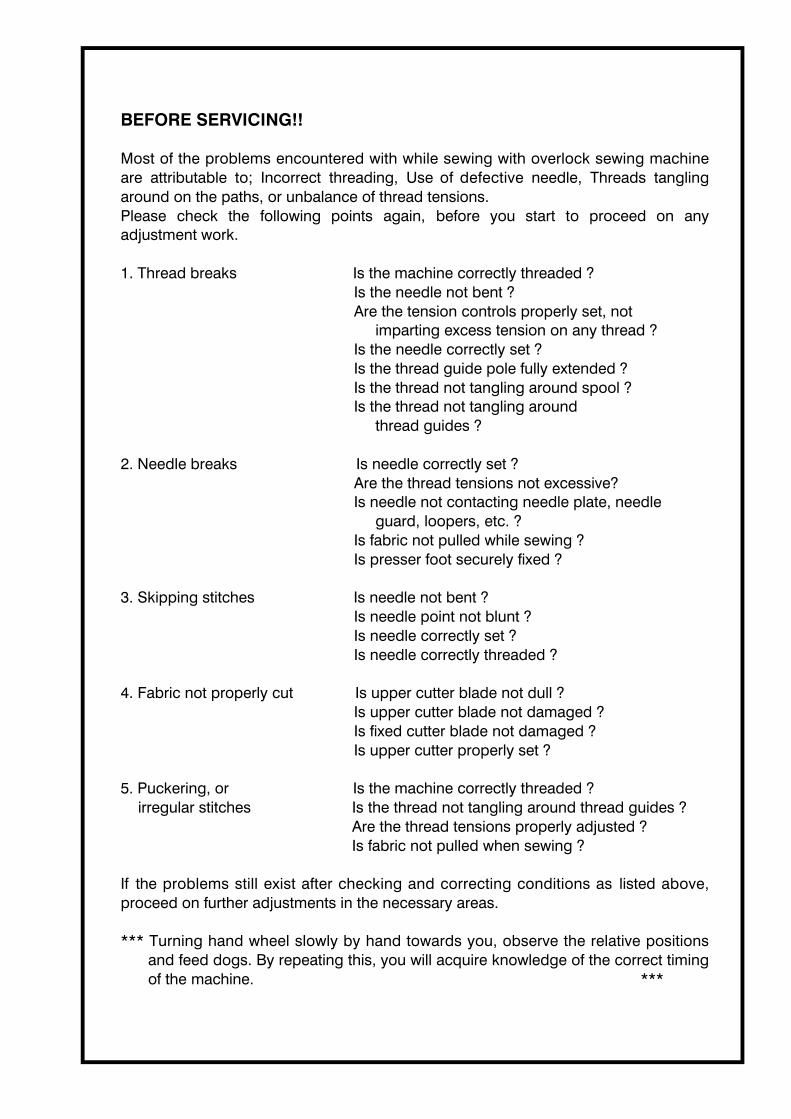
BEFORE SERVICING!!
Most of the problems encountered with while sewing with overlock sewing machine are attributable to; Incorrect threading, Use of defective needle, Threads tangling around on the paths, or unbalance of thread tensions.Please check the following points again, before you start to proceed on any adjustment work.
1. Thread breaks ・・・・・・・・・・・・・・・ Is the machine correctly threaded ? Is the needle not bent ?Are the tension controls properly set, not
imparting excess tension on any thread ?Is the needle correctly set ?Is the thread guide pole fully extended ?Is the thread not tangling around spool ?Is the thread not tangling around
thread guides ?
2. Needle breaks ・・・・・・・・・・・・・・・・Is needle correctly set ? Are the thread tensions not excessive?Is needle not contacting needle plate, needle
guard, loopers, etc. ?Is fabric not pulled while sewing ?Is presser foot securely fixed ?
3. Skipping stitches ・・・・・・・・・・・・ Is needle not bent ? Is needle point not blunt ?Is needle correctly set ?Is needle correctly threaded ?
4. Fabric not properly cut ・・・・・・・・Is upper cutter blade not dull ? Is upper cutter blade not damaged ?Is fixed cutter blade not damaged ?Is upper cutter properly set ?
5. Puckering, or ・・・・・・・・・・・・・・・・ Is the machine correctly threaded ? irregular stitches Is the thread not tangling around thread guides ?
Are the thread tensions properly adjusted ?Is fabric not pulled when sewing ?
If the problems still exist after checking and correcting conditions as listed above, proceed on further adjustments in the necessary areas.
*** Turning hand wheel slowly by hand towards you, observe the relative positions and feed dogs. By repeating this, you will acquire knowledge of the correct timing of the machine. ***

SECTION 1 -2 PAGE 2
086・ 087
TOOL LIST
TOOL # DESCRIPTION RELATED PAGE OF SERVICE MANUALT-12 HEXAGONAL BOX DRIVER
5.0mm[3] WIRING OF TERMINAL BLOCK
T-22 SPANNER 5.5MM-6.0MM 2-17 POSITIONING OF FIXED CUTTER
T-24 SPANNER 7.0MM-8.0MM 2- 3 NEEDLE DISTANCE TO LOWER LOOPER POINT2- 5 NEEDLE CLEARANCE TO LOWER LOOPER2- 8 NEEDLE DISTANCE TO UPPER LOOPER POINT
T-31 HEXAGONAL DRIVER 1.5MM 2- 6 NEEDLE GUARD POSITION2-17 POSITIONING OF FIXED CUTTER
T-32 HEXAGONAL DRIVER 2.0MM 2- 8 NEEDLE DISTANCE TO UPPER LOOPER POINT2-10 CLEARANCE BETWEEN UPPER AND LOWER LOOPER2-17 POSITIONING OF FIXED CUTTER
T-33 HEXAGONAL DRIVER 2.5MM 2- 2 NEEDLE HEIGHT2- 7 NEEDLE AND LOWER LOOPER TIMING2- 9 UPPER LOOPER TIMING2-12 PRESSER FOOT HEIGHT2-14 FEED DOG TIMING2-15 MOVING CUTTER TIMING
T-44 HEXAGONAL L WRENCH 3.0MM
2- 8 NEEDLE DISTANCE TO UPPER LOOPER POINT2-10 CLEARANCE BETWEEN UPPER AND LOWER LOOPER2-20 SETTING SUPPORT PLATE OF TWO THREAD CONVERTOR
T-5 MINUS DRIVER 2-13 FEED DOG HEIGHT
T-6 PLUS DRIVER [1] DISASSEMBLING/ASSEMBLING OF COVERS2- 4 LOWER LOOPER HEIGHT2- 6 NEEDLE GUARD POSITION2-11 OSCILLATING THREAD GUIDE POSITION2-16 REPLACING FIXED CUTTER2-21 REPLACING THREAD CUTTER

SECTION 1PAGE 1
( 2 )
( 1 )T-6
( 3 )T-6
( 4 )
( 5 ) ( 6 ) ( 7 )
[1] DISASSEMBLING / ASSEMBLING OF COVERS
1. Face cover① Loosen screw (1) and take out face cover (2).
* Re-assembling should be done in the reverse way.
2. Top cover① Loosen each screw (3) and take out top covers (4), (5), (6) and (7).
* Take out face cover before removing top cover (4).
* Re-assembling should be done in the reverse way.
( 1 2 )
( 1 3 )
T-6
SECTION 1PAGE 2
( 9 )
( 8 )
( 1 0 )
T-6
T-6
( 1 1 )
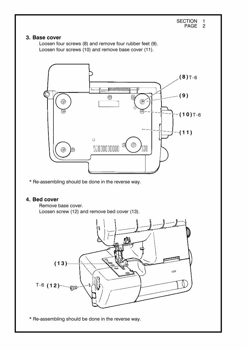
3. Base cover① Loosen four screws (8) and remove four rubber feet (9).② Loosen four screws (10) and remove base cover (11).
* Re-assembling should be done in the reverse way.
4. Bed cover① Remove base cover.② Loosen screw (12) and remove bed cover (13).
* Re-assembling should be done in the reverse way.

SECTION 1PAGE 3
A
( b )
( 1 4 )
( a )・( b )( a )T-6
B( 1 5 )
( 1 6 )
( 1 6 )
( 1 5 )
( 1 7 )T-6
( 1 8 )
5. Side cover① Remove base cover.
② Take out two screws (14).
③ Pushing back cover (15) to direction A, remove side cover (16) from fitting hook (a), (b) of back cover and take out side cover (16). Pay attention to fitting hook (a) as it is easy to break.
* Re-assembling should be done in the reverse way.
6. Front cover① Remove two screws (17) and take out front cover (18).
* Re-assembling should be done fitting to other covers exactly.

SECTION 1PAGE 4
( 2 0 )( 1 9 ) ( 2 2 )( 2 3 )
T-6
T -6( 2 1 )
( c )
7. Main cover① Remove face cover, top covers, side cover and front cover.
② Loosen two screws (19) and take out cord guide (20).
③ Remove two screws (21) and take out main cover (22) with attention to fitting hook (c).
* Re-assembling should be done in the reverse way.
See {2-19: Position of cord guide and thread guide for take up lever} when cord guide (20) and thread guide (23) for take up lever is set.

SECTION 2 -0 PAGE 1
[2] VARIOUS ADJUSTMENTS
2 - 0 ADJUSTMENT AREAS AND TIMING GAUGE
2 - 1 PROCEDURES TO CHECK TIMING OF NEEDLE AND LOOPERS
2 - 2 NEEDLE HEIGHT
2 - 3 NEEDLE DISTANCE TO LOWER LOOPER POINT
2 - 4 LOWER LOOPER HEIGHT
2 - 5 NEEDLE CLEARANCE TO LOWER LOOPER
2 - 6 NEEDLE GUARD POSITION
2 - 7 NEEDLE AND LOWER LOOPER TIMING
2 - 8 NEEDLE DISTANCE TO UPPER LOOPER POINT
2 - 9 UPPER LOOPER TIMING
2 - 10 CLEARANCE BETWEEN UPPER AND LOWER LOOPER
2 - 11 OSCILLATING THREAD GUIDE POSITION
2 - 12 PRESSER FOOT HEIGHT
2 - 13 FEED DOG HEIGHT
2 - 14 FEED DOG TIMING
2 - 15 MOVING CUTTER TIMING
2 - 16 REPLACING FIXED CUTTER
2 - 17 POSITIONING OF FIXED CUTTER
2 - 18 ADJUSTMENT OF THREAD TENSION REGULATORS
2 - 19
2 - 20 SETTING SUPPORT PLATE OF TWO THREAD CONVERTOR* For the machine with this feature only.
2 - 21 REPLACING THREAD CUTTER* For the machine with this feature only.
*** Always use "HA × 1SP" #14 needle for adjustments. ***(Sharp point)

SECTION 2 -0 PAGE 2
2 - 1 62 - 1 7
2 - 1 7
2 - 6 12 - 1 42 - 2 1
2 - 1 3
2 - 22 - 1 2
2 - 1 8
2 - 8 12 - 1 02 - 2 0
2 - 8 12 - 1 1
2 - 42 - 6
2 - 32 - 5
2 - 9
2 - 7
2 - 1 42 - 1 5
ADJUSTMENT AREAS
SECTION 2 -0 PAGE 3
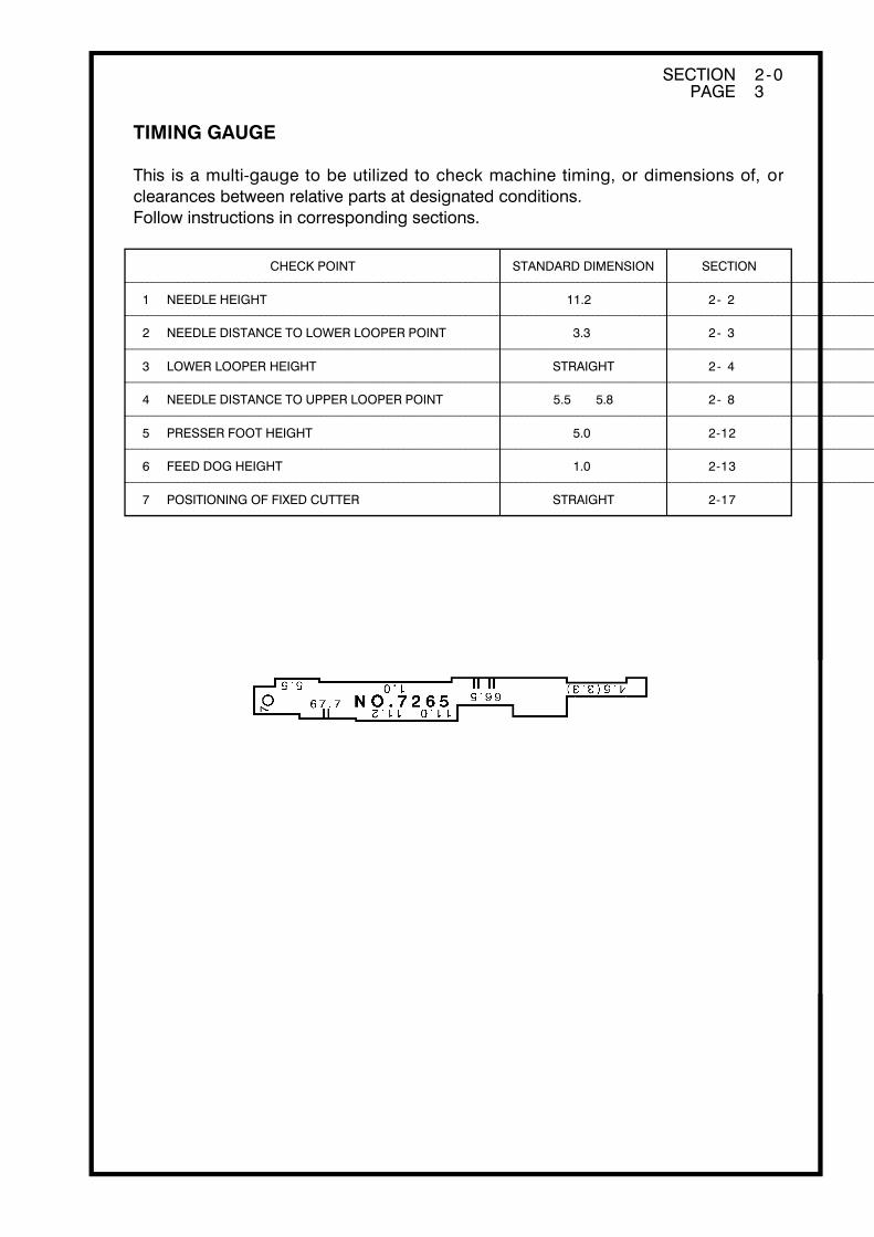
CHECK POINT STANDARD DIMENSION
1
2
3
4
5
6
7
LOWER LOOPER HEIGHT
NEEDLE DISTANCE TO LOWER LOOPER POINT
NEEDLE HEIGHT
NEEDLE DISTANCE TO UPPER LOOPER POINT
PRESSER FOOT HEIGHT
FEED DOG HEIGHT
POSITIONING OF FIXED CUTTER
3.3
11.2
5.0
1.0
SECTION
STRAIGHT
STRAIGHT
5.5 ~ 5.8
2- 2
2- 3
2- 4
2- 8
2-12
2-13
2-17
④ ⑥ ⑦
①② ⑤
③
TIMING GAUGE
This is a multi-gauge to be utilized to check machine timing, or dimensions of, or clearances between relative parts at designated conditions.Follow instructions in corresponding sections.

SECTION 2 -1 PAGE 1
STEP 1 Needle height (SEC. 2 -2)
STEP 2 Needle distance to lower looper point (SEC. 2 -3)
STEP 3
STEP 4 Repeat Step 2.
Lower looper height (SEC. 2 -4)
STEP 5 Needle clearance to lower looper (SEC. 2 -5)
STEP 6 Repeat Step 2.
STEP 8 Repeat Step 5.
STEP 7 Needle Guard position (SEC. 2 -6)
STEP 9 Needle and lower looper timing (SEC. 2 -7)
STEP 11 Upper looper timing (SEC. 2 -9)
STEP 12 Clearance between upper and lower loopers (SEC. 2 -10)
STEP 14 Oscillating thread guide position (SEC. 2 -11)
STEP 15 Sewing test
STEP 10 Needle distance to upper looper point (SEC. 2 -8)
STEP 13 Repeat Step 10.
2-1 PROCEDURES TO CHECK TIMING OF NEEDLE AND LOOPERS

SECTION 2 -2 PAGE 1
Left needle
( 2 )
( 1 )
( 3 )
T-33( 2 )
( 1 )
( 3 )
2-2 NEEDLE HEIGHT* The checking must be carried out on the left needle.
Checking:
1. Remove presser foot.
2. Set needle (#14 "HA × 1SP") correctly in position.
3. Turning hand wheel, bring up needle at highest point.
4. Check height of left needle point from needle plate surface with part ① 11.2 of multi-gauge.
Standard dimension: 11.2 mm
* Apply the gauge slantwise as illustrated so as not to be obstructed by the right needle.
Adjustment:
1. Remove face cover.
2. Set needle bar (1) at its highest position.
3. Loosen screw (3) on needle bar clamp (2), and adjust needle bar height to the standard dimension, keeping set angle.
4. Tighten screw (3) after adjustment.

SECTION 2 -3 PAGE 1
( 2 )
( 1 )
T-24
2-3 NEEDLE DISTANCE TO LOWER LOOPER POINT
Checking:
1. Remove presser foot and needle plate.
2. Turning hand wheel, move lower looper to its extreme left end position.
3. Check needle distance to lower looper point by using part ② 3.3 of multi-gauge.
Standard dimension: 3.3 mm
Adjustment:
1. Under checking condition, loosen bolt (2) on lower looper base (1).
2. Adjust set angle of base (1) to obtain standard dimension, keeping its axlewise position on shaft.
3. Tighten bolt (2) after adjustment.

SECTION 2 -4 PAGE 1
Gauge
Needle plate
Lower looper
Upper looper
Needle plate surface
Right side
Gauge
( 2 )
T-24
( 1 )
2-4 LOWER LOOPER HEIGHT
Checking:
1. Turning hand wheel manually, move center of thread hole of lower looper to right side of needle plate.
2. Check to see if lower looper height is 0 - 0.1 mm from needle plate surface with part ③ of multiple gauge.
Adjustment:
1. Under checking condition, loosen bolt (2) on lower looper base (1).
2. Adjust vertical position of lower looper.
3. Tighten bolt (2) after adjustment.

SECTION 2 -5 PAGE 1
( 2 )
T-24
( 1 )
2-5 NEEDLE CLEARANCE TO LOWER LOOPER
Checking:
1. Remove presser foot and needle plate.
2. Turning hand wheel, move lower looper point to come to the center line of the needle, and check clearance between needle and lower looper.
Standard dimension: 0 - 0.1 mm
Adjustment:
* When Left needle clearance is much different from Right needle clearance, needle bar may be at incorrect position. Check and adjust it following to {2 - 2: Needle height}.
1. Under checking condition, loosen bolt (2) on lower looper base (1).
2. Keeping the set angle, make axlewise adjustment of base (1).
3. Tighten bolt (2) after adjustment.
* After adjustment, check {2 - 3: Needle Distance to lower looper point}.

SECTION 2 -6 PAGE 1
a
( 3 )
( 2 )
( 1 )
T-31
T-6
2-6 NEEDLE GUARD POSITION
Needle guard AChecking:
1. Turning hand wheel manually, move needle to its lowest position.
2. Check if needle point aligns with corner of needle guard A.
3. Check if the clearance between needle guard and needle is standard.
Standard dimension: 0 - 0.3 mm
Adjustment:
1. Loosen screw (2) of needle guard A (1) and adjust set angle of needle guard A (1).
2. Keeping set angle, turn screw (3) and adjust the clearance between needle guard and needle.
3. After adjustment, tighten screw (2) securely, keeping set angle of needle guard.

SECTION 2 -6 PAGE 2
( 6 )
( 4 )( a )
T-6
( 5 )
Needle guard BChecking:
1. Check if part (a) of needle guard B (4) touches under side of fitting place of needle plate on bed.
2. Check if the clearance between needle and needle guard B (4) is standard.
Standard dimension: 0.1 - 0.3 mm
Adjustment:
1. Loosen screws (5), (6) and adjust the clearance between needle and needle guard B (4) under the condition that part (a) touches under side of fitting place of needle plate on bed.
2. Tighten screw (5).
3. Tighten screw (6) referring to {2 - 21: Replacing thread cutter}.

T-33
( 2 )
( 1 )
SECTION 2 - 7 PAGE 1
2-7 NEEDLE AND LOWER LOOPER TIMING
* Before proceeding, check {2 - 3: Needle distance to lower looper point}.
Checking:
1. Turning hand wheel manually, move lower looper point to align with left side of left needle.
2. At this point, check if looper point comes in the center of the cut on the back of needle.
Adjustment:
1. Remove base cover.
2. Loosen 2 screws (2) on eccentric cam (1).
3. Adjust set angle of cam (1) to obtain correct timing.
4. Tighten 2 screws (2) after adjustment.

SECTION 2 -8 PAGE 1
Left needle
( 4 )
T-24
( 5 )
( 2 )
( 1 )
T-32
( 3 )
T-44
2-8 NEEDLE DISTANCE TO UPPER LOOPER POINT
* The checking must be carried out on the left needle.
Checking:
1. Turning hand wheel, move upper looper to its extreme left end position.2. Check if the fitting position of upper looper is almost center of shaft.
a=b3. Using part ④ 5.5 of multi-gauge, check the needle distance to the looper point.
Standard dimension: A: 5.5 - 5.8 mm
Adjustment:
1. Loosen screw (1) and remove support plate of two thread convertor (2) (when machine has it).
2. Loosen screw (3) in the hole of screw (1) and correct upper looper position.3. Tighten screw (3) after checking {2 - 10: Clearance between upper and
lower loopers}.4. Loosen screw (5) of arm (4) and turning arm (4) adjust set angle of the arm (4)
to the standard.5. After adjustment, tighten screw (2) securely.
* Check {2 - 9: Upper and lower looper timing} after adjustment.
SECTION 2 -9 PAGE 1
( B )
T-33
( 2 )
( 1 )
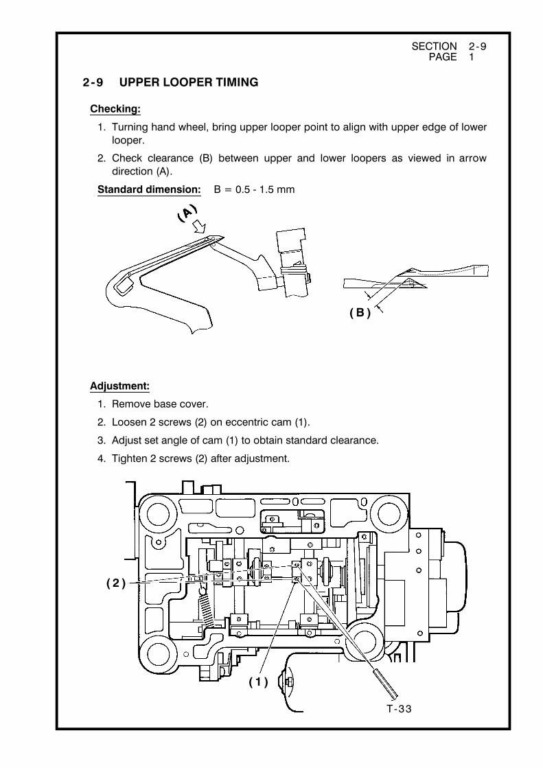
2-9 UPPER LOOPER TIMING
Checking:
1. Turning hand wheel, bring upper looper point to align with upper edge of lower looper.
2. Check clearance (B) between upper and lower loopers as viewed in arrow direction (A).
Standard dimension: B = 0.5 - 1.5 mm
Adjustment:
1. Remove base cover.
2. Loosen 2 screws (2) on eccentric cam (1).
3. Adjust set angle of cam (1) to obtain standard clearance.
4. Tighten 2 screws (2) after adjustment.

SECTION 2 -10 PAGE 1
( A )
( 2 )
( 1 )
T-32
T-44
( 3 )
2-10 CLEARANCE BETWEEN UPPER AND LOWER LOOPERS
Checking:
1. Turning hand wheel, bring upper looper point to the close proximity to lower looper.
2. Check clearance (A) between upper and lower loopers.
Standard dimension: A = 0 - 0.1 mm
Adjustment:
1. Remove screw (1) and take out support plate of two thread convertor (when machine has it).
2. Loosen screw (3) in hole of screw (1).
3. Adjust set angle of upper looper to obtain standard clearance (A) between two loopers.
4. Tighten screw (3) after adjustment.
* Check {2 - 8: Needle distance to upper looper} and {2 - 9: Upper looper timing} after adjustment.
SECTION 2 -11 PAGE 1
( 1 )
T-6
( 2 )
( A )
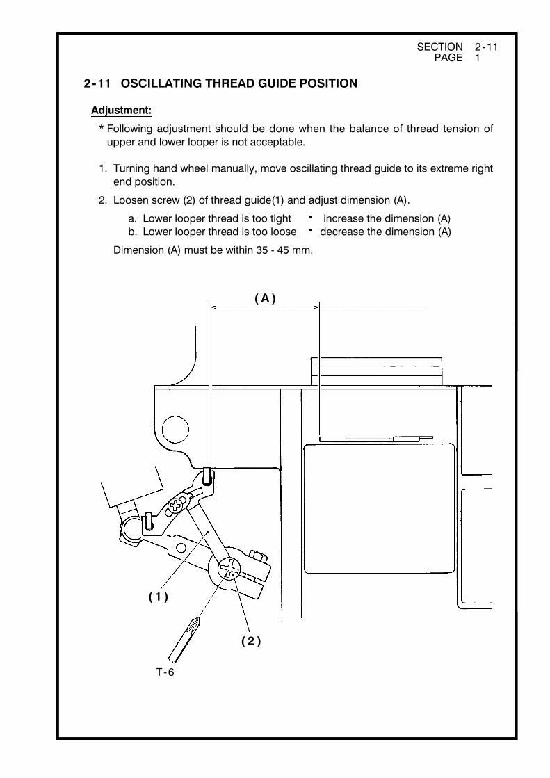
2-11 OSCILLATING THREAD GUIDE POSITION
Adjustment:
* Following adjustment should be done when the balance of thread tension of upper and lower looper is not acceptable.
1. Turning hand wheel manually, move oscillating thread guide to its extreme right end position.
2. Loosen screw (2) of thread guide(1) and adjust dimension (A).
a. Lower looper thread is too tight increase the dimension (A) b. Lower looper thread is too loose decrease the dimension (A)
Dimension (A) must be within 35 - 45 mm.

SECTION 2 -12 PAGE 1
Gauge4.5
( 2 )
( 1 )
( 4 )
T-33
( A )
( 1 )( 3 )
( 4 )
( 2 )
( A )
( 1 )( 3 )
( 4 )
( 2 )
2-12 PRESSER FOOT HEIGHT
Checking:
1. Increase pressure and raise presser foot.
2. Using part ⑤ 4.5 of multi-gauge, check clearance between needle plate and presser foot.
Standard dimension: 5.0 mm
Adjustment:
1. Remove face cover.
2. Under checking condition, loosen screw (2) on the presser bar holder (1).
3. Adjust presser bar (4) height with presser bar guide block (1) applying upper end (A) of guide plate (3).
4. After adjustment, check presser foot direction and tighten screw (2).* Presser bar (4) should not be turned.

SECTION 2 -13 PAGE 1
1 .0
Needle plate
( 2 )
( 4 )
( 3 ) ( 1 )
T-5
2-13 FEED DOG HEIGHT
Checking:
1. Remove presser foot.
2. Turning hand wheel manually, bring up feed dogs at the heighest position.
3. Using part ⑥ 1.0 of multi-gauge, check feed dog height from needle plate surface.
Standard dimension: 1.0 mm
4. Check if front feed dog height is 0.1 - 0.2 mm from rear feed dog.
Adjustment:
1. Loosen two screws (2) of rear feed dog (1) and adjust rear feed dog height to standard.
2. After adjustment, tighten screw (2) securely.
3. Loosen two screws (4) of front feed dog (3) and adjust front feed dog height so that front feed dog height is 0.1 - 0.2 mm from rear feed dog.
4. After adjustment, tighten screw (4) securely.

SECTION 2 -14 PAGE 1
( 1 )
( a )
T-33
( 3 )
( 2 )
2-14 FEED DOG TIMING
* Feed dog timing should be checked in the sequence of its vertical motion and lateral movement.
Vertical motionChecking:
1. Set stitch length control at "1" and differential feed dial at "1".
2. Turning hand wheel manually, check and see if the clearance between right needle point and rear feed dog (1) is around 1 mm when the height of rear feed dog (1) is same as the needle plate surface (a).
Adjustment:
1. Remove base cover.
2. Loosen two screws (3) of eccentric cam (2).
3. Turning eccentric cam (2), adjust set angle to obtain correct timing.
4. After adjustment, tighten two screws (3) securely.

( a )
SECTION 2 -14 PAGE 2
T-33
( 2 )
( 1 )
Lateral movementChecking:
1. Set stitch length dial at "5" and differential feed dial at "1".
2. Turning hand wheel manually, check and see if needle point is about 2 mm from needle plate surface (a) when feed dog finishes its stroke.
Adjustment:
1. Remove bed cover.
2. Loosen two screws (2) of horizontal feeding cam (1).
3. Turning feeding cam (1), adjust position of feed dog correctly.
4. After adjustment, tighten two screws (2) securely.
SECTION 2 -15 PAGE 1
T -33
( 2 )
( 1 )
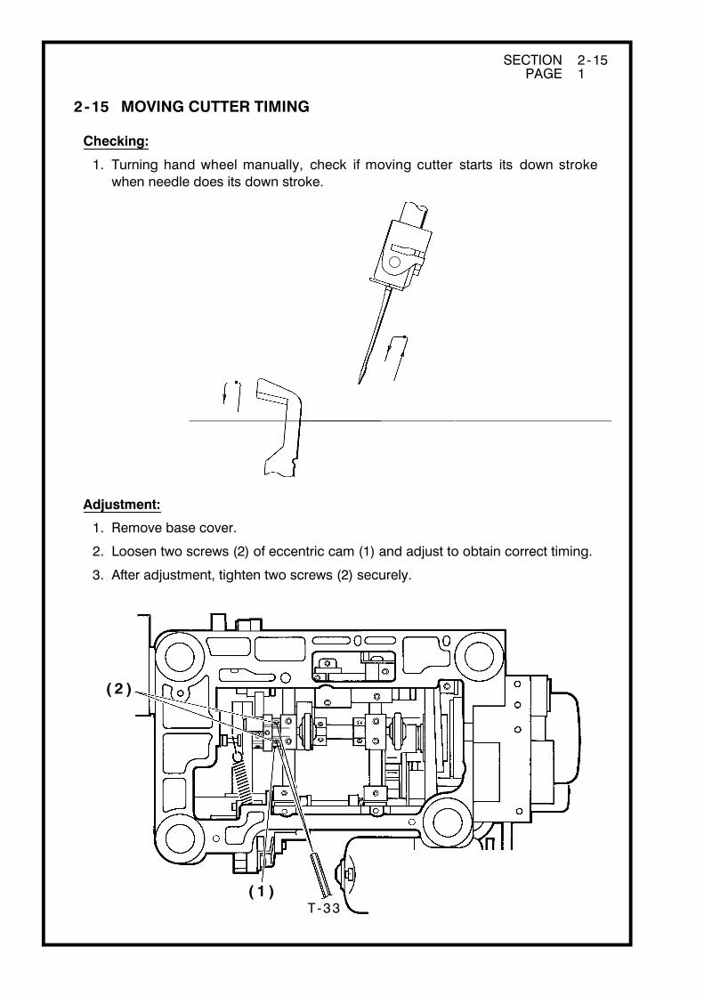
2-15 MOVING CUTTER TIMING
Checking:
1. Turning hand wheel manually, check if moving cutter starts its down stroke when needle does its down stroke.
Adjustment:
1. Remove base cover.
2. Loosen two screws (2) of eccentric cam (1) and adjust to obtain correct timing.
3. After adjustment, tighten two screws (2) securely.
SECTION 2 -16 PAGE 1
( 1 )
T-6
T -6
( 5 )( 4 )
( 2 )
( 3 )
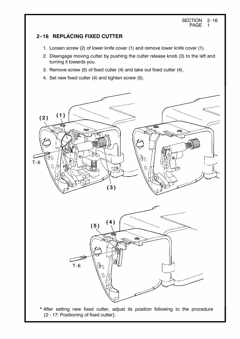
2-16 REPLACING FIXED CUTTER
1. Loosen screw (2) of lower knife cover (1) and remove lower knife cover (1).
2. Disengage moving cutter by pushing the cutter release knob (3) to the left and turning it towards you.
3. Remove screw (5) of fixed cutter (4) and take out fixed cutter (4).
4. Set new fixed cutter (4) and tighten screw (5).
* After setting new fixed cutter, adjust its position following to the procedure {2 - 17: Positioning of fixed cutter}.

T-6
T -6
( 1 )( 2 )
( 3 )
( B )
( A )
Needle plate
( 3 )
( 4 )( A ) ( B )
( 5 )
T-32
SECTION 2 -17 PAGE 1
2-17 POSITIONING OF FIXED CUTTER
Checking (1):
1. Set overedge cutting width dial at "6".
2. Check and see if sides of fixed cutter (1) and needle plate (2) come in alignment as illustrated.
Adjustment (1):
1. If not, loosen 2 screws (4) on collar (3) and adjust shaft (5) in either way until (A) and (B) come in alignment.
2. After adjustment, tighten 2 screw (4) securely.

SECTION 2 -17 PAGE 2
⑦
( 7 )
T-24
( 1 )
( 6 )
( D ) ( C )
T-31
Very slight clearance
Checking (2):
1. Check and see if the blade (C) of fixed cutter (1) is parallel with upper surface of needle plate (D).Use part ⑦ of multi-gauge for the purpose, as illustrated.
Adjustment (2):
1. Loosen screw (6) of fixed cutter (1), and adjust cutter position up or down so that its blade (C) comes to level off with upper surface of needle plate (D).
2. Tighten screw (6) securely after adjustment.
Checking (3):
1. Turning the cutter release knob, return moving cutter to normal position.
2. Check and see if there is a slight clearance between fixed cutter and moving cutter at front side. (Only paper for copy can be inserted in this clearance.)
Adjustment (3):
1. Turning screw (7), move fixed cutter to obtain parallel alignment of fixed cutter blade and needle plate.

SECTION 2 -18 PAGE 1
( 1 )
( 2 )
( 3 )
0
B
A
( 1 )
( 4 )
( 5 )
2-18 ADJUSTMENT OF THREAD TENSION REGULETORS
* This adjustment is done when the pressure of thread tension regulators is not correct at standard "4".
A. Fine adjustment (This adjustment is made within ±1 scale)
Set tension dial at "0" or "9". Insert the driver ( T - 32 or small driver) into the concave (3) of dial tension ring (2) and turn only dial tension ring (2) to direction A or B.
a. Tension pressure is too low Set the dial at "9" and turn dial tension ring (2) to the direction A.
b. Tension pressure is too high Set the dial at "0" and turn dial tension ring (2) to the direction B.
B. Adjustment which can not be done within fine adjustment
1. Remove top cover.
2. Take out E-washer (4) and pull out the dial (1). (Pay attention to flat washer and wave washer when removing.)
3. Sewing, adjust the tension by turning screw (5).
4. Set dial tension applying number 4 of dial to pointer on top cover.Be sure not to move the screw (5).
SECTION 2 -19 PAGE 1
( 2 ) ( 3 )
( 1 )
( a )
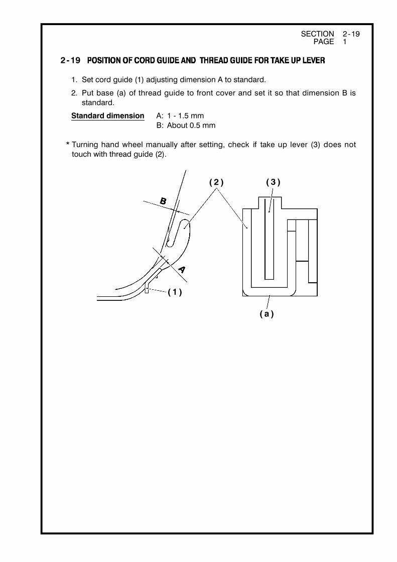
2-19
1. Set cord guide (1) adjusting dimension A to standard.
2. Put base (a) of thread guide to front cover and set it so that dimension B is standard.
Standard dimension A: 1 - 1.5 mmB: About 0.5 mm
* Turning hand wheel manually after setting, check if take up lever (3) does not touch with thread guide (2).

SECTION 2 -20 PAGE 1
T-44
( 1 )
( 2 )
T-44
( 1 )
( 2 )
T-44
( 1 )
( 2 )
( a )
( b )
2-20 SETTING SUPPORT PLATE OF TWO THREAD CONVERTOR
* For the machine with this feature only.
1. Insert the top of two thread convertor (a) into thread hole (b) of upper looper and set the support plate (2) in condition that two thread covertor pushes upper looper lightly and tighten screw (1).

SECTION 2 -21 PAGE 1
T-6
( 5 )
( 5 )( a )
( 6 ) ( 2 )
( 3 )
( 1 )
( 6 )
( d ) ( e )
( 4 )( 2 )
Re-assembling
T-6
T -6( 3 )
2-21 REPLACING THREAD CUTTER
* For the machine with this feature only.Remove bed cover and needle plate before replacement.
Moving cutter
1. Remove screw (3) and take out spring (2) and moving cutter (1).
2. Shaft (4) should be at center of long hole (a) of spring (2) when it is set.b ≒ c
Fixed cutter
1. Remove screw (5) and take out fixed cutter (6).
2. Lower side (d) of fixed cutter (6) should be almost paralleled with surface (e) of bed when it is set.
SECTION 3 -1 PAGE 1
C M S L
F C
MS
L
C M S L
M L
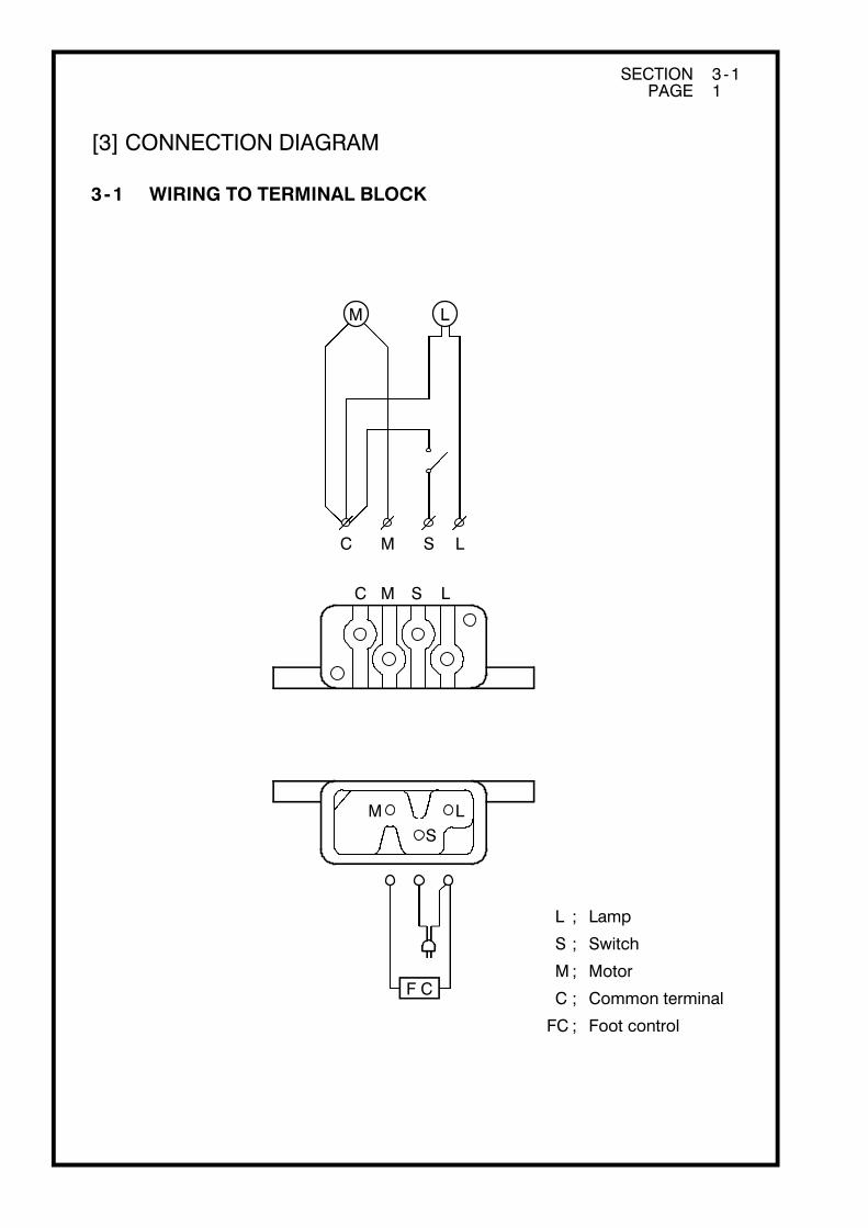
L ; Lamp
S ; Switch
M ; Motor
C ; Common terminal
FC ; Foot control
[3] CONNECTION DIAGRAM
3-1 WIRING TO TERMINAL BLOCK