ORIGINAL INSTRUCTIONS Versa-MaticOperating Manual
4
VS Versa-Sense ™ II Electronic Leak Detector VERSAMATIC ® Warren Rupp, Inc. • A Unit of IDEX Corporation © Copyright 2019 Warren Rupp, Inc. All rights reserved SERVICE & OPERATING MANUAL ORIGINAL INSTRUCTIONS 800 North Main Street, Mansfield, OH 44902 USA Phone: (419) 526-7296 • www.versamatic.com ACCESSORIES SPECIFICATIONS 115 Volt Units Power Supply: 100 VAC or 110-120VAC, 50 Milliamp, Current Draw Output Supply: 110-120VAC, 100 Watt Power, Maximum (1 Amp) 220Volt Units Power Supply: 220-240VAC, 25 Milliamp, Current Draw Output Supply: 220-240VAC, 100 Watt Power, Maximum (.5 Amp) ITEM PART DESCRIPTIONS AND PART NUMBERS P29-800TF10 Electronic Leak Detector W/ 10' Leads and PTFE Probes P29-800 Electronic Leak Detector (Unit Only) P29-804 10' Lead and PTFE Probe (Two Required Per Unit) A Unit of IDEX Corporation 800 N. Main St. Mansfield, OH 44902 Phone: (419) 526-7296 versamatic.com
Transcript of ORIGINAL INSTRUCTIONS Versa-MaticOperating Manual
VSVersa-Sense™ II Electronic Leak Detector
VERSAMATIC®
Warren Rupp, Inc. • A Unit of IDEX Corporation © Copyright 2019
Warren Rupp, Inc. All rights reserved
SERVICE & OPERATING MANUALORIGINAL INSTRUCTIONS
800 North Main Street, Mansfield, OH 44902 USA Phone: (419) 526-7296 • www.versamatic.com
A C C E S S O R I E S
Vers
a-M
atic
Oper
atin
g M
anual VSVersa-Sense™ II
Electronic Leak Detector
SPECIFICATIONS115 Volt UnitsPower Supply: 100 VAC or 110-120VAC, 50 Milliamp, Current DrawOutput Supply: 110-120VAC, 100 Watt Power, Maximum (1 Amp)220Volt UnitsPower Supply: 220-240VAC, 25 Milliamp, Current DrawOutput Supply: 220-240VAC, 100 Watt Power, Maximum (.5 Amp)
ITEM PART DESCRIPTIONS AND PART NUMBERSP29-800TF10 Electronic Leak Detector W/ 10' Leads and PTFE ProbesP29-800 Electronic Leak Detector (Unit Only)P29-804 10' Lead and PTFE Probe (Two Required Per Unit)
A Unit of IDEX Corporation
800 N. Main St.
Mansfield, OH 44902
Phone: (419) 526-7296
versamatic.com

vs2sm-rev04191 • Versa-Sense II www.versamatic.com
Versa-Sense II Electronic Leak DetectorProbe Installation
Versa-Matic® VERSA-SENSE II OM
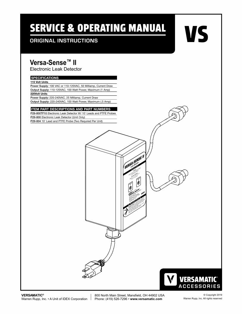
The VERSA-SENSE II Electronic Leak Detectorconsists of a modular control unit encased in awatertight enclosure and two detection probes. Allof these items are wired together as noted on theschematic illustration Figure A and Figure D.
The VERSA-SENSE II Electronic Leak Detectorsenses pumped liquid entering the air chambers ofthe pump and works on the principle of conduc-tance. The probes are installed into the bottomboss on the air chambers (E1, E4, E2, E3, and U2pump models.) When the diaphragm fails, theprobe is exposed to the pumped liquid. This pro-duces a low current change of 1.2 volts DC (<1 mil-liamp) which signals the control unit. One of the twoindicator lights signal which diaphragm has failed,and which air chamber has been contaminated bypumped fluid.
To install the probe, first back-twist the cablecounterclockwise to avoid wire twist when theprobe is threaded clockwise into the 1/4" NPTboss ports. Apply PTFE tape or a small amount ofthread sealant to the threads prior to insertion.
VERSA-SENSE II Electronic Leak Detector
Hazardous voltage. This LeakDetector is an electrical device. It shouldbe wired by only qualified, licensedelectricians. The cover should never beremoved except by authorized, licensedelectricians. Failure to heed this warningmay result in electric shock, personallasting injury or death.Power shall be disconnected beforeenclosure is opened.Enclosure shall be closed before poweris restored.
WARNING
Probe Installation
PUMP
10’ LEAD WIRES
PROBEASSEMBLY
VERSA-SENSE IIDETECTOR CONTROL UNIT
P/N P29-800 (NEMA1, 2, 3, 4, 4x, 5, 12 & 12)
NOTE: The VERSA-SENSE II Leak Detector willdetect any moisture that pools at the bottom ofthe air chamber. Air supplies with high moisturecontent will deposit the moisture at the bottomof the pump's inner chamber. This will causethe probe to send false signals of diaphragmrupture to the control unit. When the leakdetector is used to detect diaphragm failure it isrecommended that an air line dryer be installedin the air line supply line to lessen the chance offalse signals.
WIRING ILLUSTRATIONFigure A
Versa-Matic® VERSA-SENSE II OM
The VERSA-SENSE II Electronic Leak Detectorconsists of a modular control unit encased in awatertight enclosure and two detection probes. Allof these items are wired together as noted on theschematic illustration Figure A and Figure D.
The VERSA-SENSE II Electronic Leak Detectorsenses pumped liquid entering the air chambers ofthe pump and works on the principle of conduc-tance. The probes are installed into the bottomboss on the air chambers (E1, E4, E2, E3, and U2pump models.) When the diaphragm fails, theprobe is exposed to the pumped liquid. This pro-duces a low current change of 1.2 volts DC (<1 mil-liamp) which signals the control unit. One of the twoindicator lights signal which diaphragm has failed,and which air chamber has been contaminated bypumped fluid.
To install the probe, first back-twist the cablecounterclockwise to avoid wire twist when theprobe is threaded clockwise into the 1/4" NPTboss ports. Apply PTFE tape or a small amount ofthread sealant to the threads prior to insertion.
VERSA-SENSE II Electronic Leak Detector
Hazardous voltage. This LeakDetector is an electrical device. It shouldbe wired by only qualified, licensedelectricians. The cover should never beremoved except by authorized, licensedelectricians. Failure to heed this warningmay result in electric shock, personallasting injury or death.Power shall be disconnected beforeenclosure is opened.Enclosure shall be closed before poweris restored.
WARNING
Probe Installation
PUMP
10’ LEAD WIRES
PROBEASSEMBLY
VERSA-SENSE IIDETECTOR CONTROL UNIT
P/N P29-800 (NEMA1, 2, 3, 4, 4x, 5, 12 & 12)
NOTE: The VERSA-SENSE II Leak Detector willdetect any moisture that pools at the bottom ofthe air chamber. Air supplies with high moisturecontent will deposit the moisture at the bottomof the pump's inner chamber. This will causethe probe to send false signals of diaphragmrupture to the control unit. When the leakdetector is used to detect diaphragm failure it isrecommended that an air line dryer be installedin the air line supply line to lessen the chance offalse signals.
WIRING ILLUSTRATIONFigure A
LOADLOAD
PICTOGRAM FOR FUSE FU1
POWER PROTECTION
DRY CONTACTALARM OUTPUTS
TO PROBEPICKUPBOARD
AC OR DC220V/5AMAX
OUTPUTS C6C5
1 2
TS2
C7
1TS1
FU1.5A250V
P1
CR1 CR2
FU21A250V
FU31A250V
POWERRTN
OPTIONALEXTERNAL
OUTPUTJUNCTION FOR
SOLENOIDVALVES OR
SIGNALS
LINEVOLTAGE
SELECT
INSERT SCREW DRIVERIN SLOT AND SLIDE TO
CHANGE VOLTAGECAUTION: REMOVE
POWER FIRST
115/230VAC50/60 Hz
L1 L2 G
115V
100-120VAC(HOT)
100-120VAC(HOT)
AC NeutralLoad will be energized
when LED 1 is illmunatedThis load is fused by FU2
AC NeutralLoad will be energized
when LED 2 is illmunatedThis load is fused by FU3
OUTPUTS C6C5
1 2
TS2
LOAD LOAD
Versa-Matic® VERSA-SENSE II OM
Options Conductivity
The control unit can be easily wired to an audiblealarm or pump shutdown device. For example youcan connect the leak detector unit to a solenoid,which can shut the air supply off to the pump, orsound an alarm by routing the external device intothe leak detector unit. The wires can enter throughone of the three port holes in the leak detection unit.The output connection terminal has 100 watt poweroutput and each chamber has independent connec-tions. If combining the two chambers, a four wirelead spliced before the external device would benecessary (See output connection terminal Figure B.)
The leak detector probes work under the principleof conductance. Not all pumped liquid is conduc-tive. If the diaphragm fails, the pumped product willconduct (complete the circuit) and signal the boxand the warning light will come on.
Sensitivity of the detector can be adjusted by theadjusting knobs R5 and R6. (See Figure C.) Theseadjustment knobs work independently for each side(chamber). They can be moved with a small screwdriver. These sensitivity knobs are also important insetting to detect conductance fluid at the sensitivi-ty most required. The sensitivity range of the detec-tor is adjustable from OHM (2,000 Micro MHO) to100,000 OHM (10 Micro MHO).
When sensing low conductivity, turning the screwsclockwise increases probe sensitivity.
UP
DOWN
UP
DOWN
ALMLO
ALMHI
ALMLO
ALMHISW1
TS1
R5
INC-SENSCW
INC-SENSCW
R6
SW2
2HC1HC
C3
Conductive/Non-Conductive Switch InformationNote: Pumps containing driver fluid should be filled withconductive or non-conductive fluid, depending on the fluidpumped. The driver fluid should be opposite of the pumpedproduct in order to determine diaphragm failure and lightwarning LED signal(s). This is adjusted inside the box inthe following manner:
SW1 DOWN (LED 1) = LED on w/presence ofconductive fluid and off w/absence of conductive fluid.SW1 UP (LED 1) =LED on w/absence of conductivefluid and off w/absence of conductive fluid.
— OR —
SW2 DOWN (LED 2) = LED on w/presence ofconductive fluid and off w/absence of conductive fluid.SW2 UP (LED 2) = LED on w/absence of conductivefluid and off w/absence of conductive fluid.
When sensing low conductivity, turning thescrews clockwise increases probe sensitivity.
WIRING ILLUSTRATIONFigure B
WIRING ILLUSTRATIONFigure C
The VERSA-SENSE II Electronic Leak Detector consists of modular control unit encased in a watertight enclosure and two detection probes. All of these items are wired together as noted on the schematic illustration Figure A and Figure D.
The VERSA-SENSE II Electronic Leak Detector senses pumped liquid entering the air chambers of the pump and works on the principle of conductance. The probes are installed into the bottom boss on the air chambers (E4, E2, E3, and U2 pump models.) When the diaphragm fails, the probe is exposed to the pumped liquid. This produces a low current change of 1.2 volts DC (<1 milliampere) which signals the control unit. One of the two indicator lights signal which diaphragm has failed, and which air chamber has been con-taminated by pumped fluid.
NOTE: The VERSA-SENSE II Leak Detector will detect any moisture that pools at the bottom of the air cham-ber. Air supplies with high moisture content will deposit the moisture at the bottom of the pump's inner cham-ber. This will cause the probe to send false signals of diaphragm rupture to the control unit. When the leak detector is used to detect diaphragm failure it is recom-mended that an air line dryer be installed in the air line supply line to lessen the chance of false signals.
To install the probe, first back-twist the cable counter-clockwise to avoid wire twist when the probe is threaded clockwise into the 1/2-20 UNF boss ports. Apply PTFE tape or a small amount of thread sealant to the threads prior to insertion.

vs2sm-rev0419Versa-Sense II • 2www.versamatic.com
Options Conductivity
LOADLOAD
PICTOGRAM FOR FUSE FU1
POWER PROTECTION
DRY CONTACTALARM OUTPUTS
TO PROBEPICKUPBOARD
AC OR DC220V/5AMAX
OUTPUTS C6C5
1 2
TS2
C7
1TS1
FU1.5A250V
P1
CR1 CR2
FU21A250V
FU31A250V
POWERRTN
OPTIONALEXTERNAL
OUTPUTJUNCTION FOR
SOLENOIDVALVES OR
SIGNALS
LINEVOLTAGE
SELECT
INSERT SCREW DRIVERIN SLOT AND SLIDE TO
CHANGE VOLTAGECAUTION: REMOVE
POWER FIRST
115/230VAC50/60 Hz
L1 L2 G
115V
100-120VAC(HOT)
100-120VAC(HOT)
AC NeutralLoad will be energized
when LED 1 is illmunatedThis load is fused by FU2
AC NeutralLoad will be energized
when LED 2 is illmunatedThis load is fused by FU3
OUTPUTS C6C5
1 2
TS2
LOAD LOAD
Versa-Matic® VERSA-SENSE II OM
Options Conductivity
The control unit can be easily wired to an audiblealarm or pump shutdown device. For example youcan connect the leak detector unit to a solenoid,which can shut the air supply off to the pump, orsound an alarm by routing the external device intothe leak detector unit. The wires can enter throughone of the three port holes in the leak detection unit.The output connection terminal has 100 watt poweroutput and each chamber has independent connec-tions. If combining the two chambers, a four wirelead spliced before the external device would benecessary (See output connection terminal Figure B.)
The leak detector probes work under the principleof conductance. Not all pumped liquid is conduc-tive. If the diaphragm fails, the pumped product willconduct (complete the circuit) and signal the boxand the warning light will come on.
Sensitivity of the detector can be adjusted by theadjusting knobs R5 and R6. (See Figure C.) Theseadjustment knobs work independently for each side(chamber). They can be moved with a small screwdriver. These sensitivity knobs are also important insetting to detect conductance fluid at the sensitivi-ty most required. The sensitivity range of the detec-tor is adjustable from OHM (2,000 Micro MHO) to100,000 OHM (10 Micro MHO).
When sensing low conductivity, turning the screwsclockwise increases probe sensitivity.
UP
DOWN
UP
DOWN
ALMLO
ALMHI
ALMLO
ALMHISW1
TS1
R5
INC-SENSCW
INC-SENSCW
R6
SW2
2HC1HC
C3
Conductive/Non-Conductive Switch InformationNote: Pumps containing driver fluid should be filled withconductive or non-conductive fluid, depending on the fluidpumped. The driver fluid should be opposite of the pumpedproduct in order to determine diaphragm failure and lightwarning LED signal(s). This is adjusted inside the box inthe following manner:
SW1 DOWN (LED 1) = LED on w/presence ofconductive fluid and off w/absence of conductive fluid.SW1 UP (LED 1) =LED on w/absence of conductivefluid and off w/absence of conductive fluid.
— OR —
SW2 DOWN (LED 2) = LED on w/presence ofconductive fluid and off w/absence of conductive fluid.SW2 UP (LED 2) = LED on w/absence of conductivefluid and off w/absence of conductive fluid.
When sensing low conductivity, turning thescrews clockwise increases probe sensitivity.
WIRING ILLUSTRATIONFigure B
WIRING ILLUSTRATIONFigure C
The control unit can be easily wired to an audible alarm or pump shutdown device. For example, you can connect the leak detector unit to a solenoid, which can shut the air supply off to the pump, or sound an alarm by routing the external device into the leak detector unit. The wires can enter through one of the three port holes in the leak detector unit. The output connection terminal has 100 watt power out put and each chamber has independent con-nections. If combining the two chambers, a four wire lead spliced before the external device would be necessary.(See output connection terminal Figure B.)
The leak detector probes work under the principle of conduc-tance. Not all pumped liquid is conductive. If the diaphragm fails, the pumped product will conduct (complete the circuit) and signal the box and the warning light will come on.
Sensitivity of the detector can be adjusted by the adjusting knobs R5 and R6. (See Figure C) These adjustment knobs work independently for each side (chamber). The can be moved with a small screw driver. These sensitivity knobs are also important in setting to detect conductance fluid at the sensitivity most required. The sensitivity range of the detector is adjustable from OHM (2,000 Micro MHO) to 100,000 OHM (10 Micro MHO).
When sensing low conductivity, turn the screws clockwise increases probe sensitivity.

vs2sm-rev04193 • Versa-Sense II www.versamatic.com
Versa-Sense II Schematic
©2008 IDEX Corporation VMVSIIOM-208
VERSA-MATIC® PUMP COMPANYA Unit of IDEX Corporation6017 Enterprise DriveExport, PA 15632-8969
(724) 327-7867Fax: (724) 327-4300www.versamatic.com
Versa-Matic® and Versa-Sense™ are registered tradenames and trademarks of IDEX Corporation.
Versa-Sense II Schematic
C A U T I O NFOR 220 VOLT UNITS:Plug in only to 220 volt systems. Do not havepower to the cord (do not have it plugged in)when connecting to the box terminals.
C A U T I O NFOR 115 VOLT UNITS:Plug in only to 100 volt systems. Do not havepower to the cord (do not have it plugged in)when connecting to the box terminals.
WIRING ILLUSTRATIONFigure D