Original: English only Source: Doc. 8A-9B/TEMP/36 ...ieee802.org/16/liaison/itu/134ev2.pdf · draft...
168
C:\WINDOWS\TEMP\134EV2.DOC 03.05.99 05.05.99 Source: Doc. 8A-9B/TEMP/36 Subject: Questions ITU-R 215/8 and ITU-R 140/9 Principal Rapporteurs, JRG 8A-9B DRAFT NEW RECOMMENDATION ITU-R F.BWA RADIO TRANSMISSION SYSTEMS FOR FIXED BROADBAND WIRELESS ACCESS (BWA) BASED ON CABLE MODEM STANDARDS (ANNEX B OF ITU-T REC J.112) * (Questions ITU-R 215/8 and 140/9) CONTENTS Introduction Scope References Definitions and Abbreviations Conventions Considerations Recommendation 1 General System Requirement 1. 1 Service goals 1. 2 Reference architecture 1.3 Categories of interface specification 1.4 Server location 2 Functional assumptions 2.1 Broadband wireless access (BWA) network 2.2 Equipment assumptions 2.2.1 Frequency plan 2.2.2 Compatibility with other services ____________________ * This Recommendation is intended only for fixed broadband wireless access systems based on Annex B of ITU-T Recommendation J.112 “Data over Cable Radio Frequency Interface”. INTERNATIONAL TELECOMMUNICATION UNION RADIOCOMMUNICATION STUDY GROUPS Document 9B/134-E (including Corrigendum 1) 20 April 1999 Original: English only
Transcript of Original: English only Source: Doc. 8A-9B/TEMP/36 ...ieee802.org/16/liaison/itu/134ev2.pdf · draft...

C:\WINDOWS\TEMP\134EV2.DOC 03.05.99 05.05.99
Source: Doc. 8A-9B/TEMP/36
Subject: Questions ITU-R 215/8 and ITU-R 140/9
Principal Rapporteurs, JRG 8A-9B
DRAFT NEW RECOMMENDATION ITU-R F.BWA
RADIO TRANSMISSION SYSTEMS FOR FIXED BROADBAND WIRELESS ACCESS(BWA) BASED ON CABLE MODEM STANDARDS (ANNEX B OF ITU-T REC J.112)∗∗
(Questions ITU-R 215/8 and 140/9)
CONTENTS
Introduction
Scope
References
Definitions and Abbreviations
Conventions
Considerations
Recommendation
1 General System Requirement1. 1 Service goals1. 2 Reference architecture1.3 Categories of interface specification1.4 Server location
2 Functional assumptions2.1 Broadband wireless access (BWA) network2.2 Equipment assumptions2.2.1 Frequency plan2.2.2 Compatibility with other services
____________________
* This Recommendation is intended only for fixed broadband wireless access systems based on Annex B ofITU-T Recommendation J.112 “Data over Cable Radio Frequency Interface”.
INTERNATIONAL TELECOMMUNICATION UNION
RADIOCOMMUNICATIONSTUDY GROUPS
Document 9B/134-E(including Corrigendum 1)20 April 1999Original: English only

9B/134-E
2.2.3 Fault isolation impact on other users2.3 RF channel assumptions2.3.1 Transmission upstream and downstream2.4 Transmission levels2.5 Power Control Requirements2.6 BER vs. SNR Specifications2.7 Frequency inversion
3 Communication protocols3.1 Protocol stack3.1.1 BWA CPE and BWA BTS Modems as hosts3.1.2 Data forwarding through the BWA CPE and BTS Modems3.2 The MAC forwarder3.2.1 Example rules for data-link-layer forwarding3.3 Network layer3.4 Above the network layer3.5 Data link layer3.5.1 LLC sublayer3.5.2 Link-layer security sublayer3.5.3 MAC sublayer3.6 Physical layer3.6.1 Downstream transmission convergence sublayer3.6.2 PMD sublayer
4 Physical media dependent sublayer specification4.1 Scope4.2 Upstream4.2.1 Overview4.2.2 Modulation formats4.2.3 FEC encode4.2.4 Scrambler (Randomizer)4.2.5 Preamble prepend4.2.6 Burst profiles4.2.7 Burst timing convention4.2.8 Transmit power requirements4.2.9 Fidelity requirements4.2.10 Frame structure4.2.11 Signal processing requirements4.2.12 Upstream demodulator input power characteristics4.2.13 Upstream electrical output from the CPE modem4.3 Downstream4.3.1 Downstream protocol4.3.2 Scalable interleaving to support low latency4.3.3 Downstream frequency plan4.3.4 BWA BTS output electrical4.3.5 Downstream RF input to BWA CPE4.3.6 BWA CPE Modem BER performance

9B/134-E
5 Downstream transmission convergence sublayer5.1 Introduction5.2 MPEG packet format5.3 MPEG header for BWA data-over-the-air5.4 MPEG payload for BWA data-over-the-air5.5 Interaction with the MAC sublayer5.6 Interaction with the physical layer5.7 MPEG header synchronization and recovery
6 Media access control specification6.1 Introduction6.1.1 Overview6.1.2 Definitions6.1.3 Future use6.2 MAC frame formats6.2.1 Generic MAC frame format6.2.2 Packet-based MAC frames6.2.3 ATM cell MAC frames6.2.4 Reserved PDU MAC frames6.2.5 MAC-specific headers6.2.6 Extended MAC headers6.2.7 Error-handling6.3 MAC management messages6.3.1 Message format6.3.2 MAC management messages6.4 Upstream bandwidth allocation6.4.1 The allocation map MAC management message6.4.2 Map transmission and timing6.4.3 Protocol example6.4.4 Contention resolution6.4.5 BWA CPE Modem behaviour6.4.6 Support for multiple channels6.4.7 Classes of service6.5 Timing and synchronization6.5.1 Global timing reference6.5.2 BWA CPE Modem channel acquisition6.5.3 Ranging6.5.4 Timing units and relationships6.6 Data link encryption support6.6.1 MAC messages6.6.2 Framing
7 BWA CPE modem - BWA BTS Modem interaction7.1 BWA BTS Modem initialization7.2 BWA CPE modem initialization7.2.1 Scanning and synchronization to downstream7.2.2 Obtain upstream parameters7.2.3 Message flows during scanning and upstream parameter acquisition

9B/134-E
7.2.4 Ranging and automatic adjustments7.2.5 Establish IP connectivity7.2.6 Establish time of day7.2.7 Establish security association7.2.8 Transfer operational parameters7.2.9 Registration7.2.10 Service IDs during BWA CPE Modem initialization7.2.11 Multiple-channel support7.2.12 Remote RF signal level adjustment7.2.13 Changing upstream burst parameters7.2.14 Changing upstream channels7.2.15 Fault detection and recovery7.2.16 Prevention of unauthorized transmissions
8 Supporting future new BWA CPE modem capabilities8.1 Setting up communications on an enhanced basis8.1.1 Upstream enhanced/downstream standard8.1.2 Downstream enhanced/upstream enhanced or standard8.2 Downloading BWA CPE modem operating software
9 Provision for other future capabilities9.1 Anticipated physical-layer changes9.1.1 Adding upstream channel and burst configuration settings9.1.2 Downstream channel improvements9.2 New network service requirements9.2.1 Multicast service IDs9.2.2 RSVP support for upstream traffic9.3 PID filtering capability
Annex A - Well-known addressesA.1 MAC addressesA.2 MAC service IDsA.3 MPEG PID and table_id
Annex B - Parameters and constants
Annex C - BWA CPE Modem configuration interface specificationC.1 DHCP fields used by the CPE modemC.2 BWA CPE Modem binary configuration file formatC.3 Configuration file settingsC.4 Configuration file creationC.5 BWA CPE Modem MIC calculationC.6 BWA BTS Modem MIC calculationC.6.1 Digest calculationC.7 Registration configuration settingsC.8 EncodingsC.8.1 End-of-data markerC.8.2 Pad configuration settingC.8.3 Downstream frequency configuration setting

9B/134-E
C.8.4 Upstream channel ID configuration settingC.8.5 Network access control objectC.8.6 Class of service configuration settingC.8.7 Modem capabilities configuration settingC.8.8 BWA CPE Modem Message Integrity Check (MIC) configuration settingC.8.9 BWA BTS Modem Message Integrity Check (MIC) configuration settingC.8.10 Vendor ID configuration settingC.8.11 Software upgrade filenameC.8.12 SNMP write-access controlC.8.13 SNMP MIB objectC.8.14 Vendor-specific informationC.8.15 Modem IP addressC.8.16 Service(s) not available responseC.8.17 CPE modem ethernet MAC address
Annex D - MAC sublayer service definitionD.1 Service at the BWA CPE modemD.2 MAC_CPE_Modem_802_DATA.requestD.3 MAC_CPE_Modem_DIX_DATA.requestD.4 MAC_CPE_Modem_ATM_DATA.requestD.5 MAC_CPE_Modem_802_DATA.indicationD.6 MAC_CPE_Modem_DIX_DATA.indicationD.7 MAC_CPE_Modem_ATM_DATA.indicationD.8 MAC_CPE_Modem_DATA.acknowledgment
Annex E - Example burst profilesE.1 IntroductionE.2 Example preamble sequenceE.3 Example burst profiles
Appendix A – Cable Modem Interface Documents
Figures
Figure 1-1 Transparent IP traffic through the data-over-BWA system
Figure 1-2 Data-over-BWA reference architecture
Figure 3-1 Protocol stack on the RF interface
Figure 3-2 Data forwarding through the BWA CPE Modem and BWA CPE Modem
Figure 3-3 Example condition for network loops
Figure 3-4 MAC forwarder
Figure 4-1 QPSK symbol mapping
Figure 4-2 16 QAM gray-coded symbol mapping
Figure 4-3 16 QAM differential-coded symbol mapping
Figure 4-4 Scrambler structure

9B/134-E
Figure 4-5 Nominal burst timing
Figure 4-6 Worst-case burst timing
Figure 4-7 Example frame structures with flexible burst length mode
Figure 4-8 Signal-processing sequence
Figure 4-9 TDMA upstream transmission processing
Figure 5-1 Example of interleaving MPEG packets in downstream
Figure 5-2 Format of an MPEG packet
Figure 5-3 Packet format where a MAC frame immediately follows the pointer_field
Figure 5-4 Packet format with MAC frame preceded by stuffing bytes
Figure 5-5 Packet format showing multiple MAC frames in a single packet
Figure 5-6 Packet format where a MAC frame spans multiple packets
Figure 6-1 Generic MAC frame format
Figure 6-2 Upstream MAC/PMD convergence
Figure 6-3 MAC header format
Figure 6-4 Ethernet/802.3 packet PDU format
Figure 6-5 ATM cell MAC frame format
Figure 6-6 Reserved PDU format
Figure 6-7 Timing MAC header
Figure 6-8 Management MAC header
Figure 6-9 Request MAC header format
Figure 6-10 Concatenation of multiple MAC frames
Figure 6-11 Concatenation MAC header format
Figure 6-12 Extended MAC format
Figure 6-13 MAC header and MAC management header fields
Figure 6-14 Format of packet PDU following the timing header
Figure 6-15 Upstream channel descriptor
Figure 6-16 Top-level encoding for a burst descriptor
Figure 6-17 Example of UCD encoded TLV data
Figure 6-18 MAP format
Figure 6-19 MAP information element structure
Figure 6-20 Packet PDU following the timing header
Figure 6-21 Ranging response
Figure 6-22 Generalized decision feedback equalization coefficients
Figure 6-23 BWA BTS Modem demodulator equalizer tap location definition
Figure 6-24 Example of TLV data

9B/134-E
Figure 6-25 Registration request
Figure 6-26 Example of registration request type value encodings
Figure 6-27 Registration response format
Figure 6-28 Example of registration response encoding
Figure 6-29 Upstream channel change request
Figure 6-30 Upstream channel change response
Figure 6-31 Allocation map
Figure 6-32 Protocol example
Figure 6-33 Security framing
Figure 6-34 Example of security framing at the BWA CPE Modem
Figure 6-35 Example of security framing at the BWA BTS Modem
Figure 7-1 BWA CPE Modem initialization overview
Figure 7-2 SDL notation
Figure 7-3 Obtaining upstream parameters
Figure 7-4 Message flows during scanning and upstream parameter acquisition
Figure 7-5 Ranging and automatic adjustments procedure
Figure 7-6 Initial ranging - BWA CPE Modem
Figure 7-7 Initial ranging - BWA CPE Modem (continued)
Figure 7-8 Initial ranging - BWA BTS Modem
Figure 7-9 Establishing IP connectivity
Figure 7-10 Establishing time of day
Figure 7-11 Transferring operational parameters and registration
Figure 7-12 Periodic ranging - BWA BTS Modem
Figure 7-13 Periodic ranging - BWA CPE Modem view
Figure 7-14 Changing upstream channels: BWA BTS Modem view
Figure 7-15 Changing upstream channels: BWA CPE Modem view
Figure C-1 Binary configuration file format
Figure C-2 Create TLV entries for parameters required by the BWA CPE Modem
Figure C-3 Add BWA CPE Modem MIC
Figure C-4 Add BWA BTS Modem MIC
Figure C-5 Add end of data marker

9B/134-E
Radio Transmission Systems for Fixed Broadband Wireless Access (BWA) based on CableModem Standards (Annex B of ITU-T Rec. J.112)
Introduction
Local access and other high density radio-relay service planning and system deployments haverapidly accelerated in the last few years in many countries. This acceleration is due in large part tothe trend towards increased demand and competition in the provision of high bit-rate localtelecommunications and video distribution services. Because of cost and speed of deploymentconsiderations, these developments are placing a major new focus on the provision of servicesdirectly to end-users via fixed wireless access systems.
Current Broadband Wireless Access data rates over individual circuit paths range from about1.5 Mbit/s to about 45 Mbit/s, and are expected to reach at least 310 Mbit/s within the next fewyears, as radios utilizing higher order modulation schemes become available (see RecommendationITU-R F.758).
The variety of possible Broadband FWA network configurations includes: conventional point-to-point (P-P), conventional point-to-multipoint (P-MP), and combinations thereof, e.g. P-P systemsdeployed in multisectored P-MP configurations. High density deployment of independent P-P linkssimilarly results in clusters that assume the essential characteristics of P-MP deployment. Anemerging system architecture is that of multipoint-to-multipoint (MP-MP), similar to mesh systems.
These Broadband FWA systems are predominantly deployed in dense urban, suburban, and campusenvironments where transmission path elevation angles may reach up to about 40 to 60 degrees.Links are regularly deployed on an on-demand basis to meet specific end-user requirements as theydevelop.
This Recommendation addresses fixed broadband wireless access systems, which are based on AnnexB of ITU-T Rec J.112 “Data over Cable Radio Frequency Interface”. A number of frequency bandsin the range 2.5–66 GHz can be appropriate for these systems. This and other systems, which maybe addressed in other recommendations, belong to the category of multimedia wireless systems(MWS). Multimedia Wireless Systems are wireless systems which support information exchange ofmore than one type, such as text, graphics, voice, sound, image, data and video.
Scope
This Recommendation "Radio Transmission Systems for Fixed Broadband Wireless Access (BWA)Based on Cable Modem Standards” is based on the standards approved and published by ITU-T forcable modems (specifically Annex B of ITU-T Recommendation J.112 “Data over Cable RadioFrequency Interface”), but adapts the technical parameters for use in the wireless accessenvironment, that is for BWA CPE modems. The commonality is maximized to achieve economiesof scale.

9B/134-E
References
The following ITU Recommendations and other references contain provisions which, throughreference in this text, constitute provisions of this Recommendation. At the time of publication, theeditions indicated were valid. All Recommendations and other references are subject to revision; allusers of this Recommendation are therefore encouraged to investigate the possibility of applying themost recent edition of the Recommendations and other references listed below. Lists of the currentlyvalid ITU Recommendations are regularly published.
ITU-R F.[Doc. 9/46] Draft New Recommendation ITU-R F.[Doc. 9/46] “Frequency sharing criteriabetween a land-mobile wireless access (MWA) and a fixed wireless access(FWA) system using the same equipment type as the MWA system”
ITU-R F.[Doc. 9/76] Draft New Recommendation ITU-R F.[Doc. 9/76] “Peformance andavailability requirements and objectives for fixed wireless access (FWA) toPSTN”
ITU-R F.[Doc. 9/79] Draft New Recommendation ITU-R F.[Doc. 9/79] “Vocabulary of terms for
ITU-R F.[Doc. 9/80] Draft New Recommendation ITU-R F.[Doc. 9/80] “Frequency bands for fixedwireless access (FWA) systems and the identification methodology”
ISO 8025 ISO 8025 (December 1987) - Information processing systems - Open SystemsInterconnection - Specification of the Basic Encoding Rules for AbstractSyntax Notation One (ASN.1)
ISO 8802-2 ISO/IEC 8802-2: 1994 (IEEE Std 802.2: 1994) - Informationtechnology - Telecommunications and information exchange between systems- Local and metropolitan area networks - Specific requirements - Part 2:Logical link control
ISO 8802-3 ISO/IEC 8802-3: 1996 (IEEE Std 802.3: 1996) - Information technology -Telecommunications and information exchange between systems - Local andmetropolitan area networks - Part 3: Carrier sense multiple access withcollision detection (CSMA/CD) access method and physical sublayerspecifications
ISO/IEC 10038 ISO/IEC 10038 (ANSI/IEEE Std 802.1D): 1993, Information technology -Telecommunications and information exchange between systems -Local area networks - Media access control (MAC) bridges.
ISO/IEC 10039 ISO/IEC 10039: 1991 Information technology - Open SystemsInterconnection - Local area networks - Medium Access Control (MAC)service definition.
ISO/IEC15802-1 ISO/IEC 10039: 1991 Information technology - Telecommunications andinformation exchange between systems - Local and metropolitan areanetworks - Common specifications - Part 1: Medium Access Control (MAC)service definition.
ITU-T H.222.0 ITU-T Recommendation H.222.0 (1995) | ISO/IEC 13818-1: 1996,Information technology - generic coding of moving pictures and associatedaudio information systems.
ITU-T I.361 ITU-T Recommendation I.361 - B-ISDN ATM layer specification

9B/134-E
ITU-T I.363 ITU-T Recommendation I.363 - B-ISDN ATM adaptation layer(AAL) specification
ITU-T J.83 ITU-T Recommendation J.83: Digital multi-programme systems fortelevision, sound and data services for cable distribution
ITU-T J.110 ITU-T Recommendation J.110 - Basic principles for a worldwide commonfamily of systems for the provision of interactive television services
ITU-T J.112 ITU-T Recommendation J.112 - Transmission systems for interactive cabletelevision services
ITU-T J.ini Draft ITU-T Recommendation J.ini - Network independent protocols forinteractive systems
ITU-T V-series ITU-T Recommendations V.21 - 300 bits per second duplex modemstandardized for use in the general switched telephone network
ITU-T Recommendation V.22 - 1 200 bits per second duplex modemstandardized for use in the general switched telephone network and onpoint-to-point 2-wire leased telephone-type circuits
ITU-T Recommendation V.22bis - 2 400 bits per second duplex modem usingthe frequency division technique standardized for use on the general switchedtelephone network and on point-to-point 2-wire leased telephone-type circuits
ITU-T Recommendation V.23 - 600/1 200-baud modem standardized for usein the general switched telephone network
ITU-T Recommendation V.25 - Automatic answering equipment and generalprocedures for automatic calling equipment on the general switched telephonenetwork including procedures for disabling of echo control devices for bothmanually and automatically established calls
ITU-T Recommendation V.32 - A family of 2-wire, duplex modems operatingat data signalling rates of up to 9 600 bit/s for use on the general switchedtelephone network and on leased telephone-type circuits
ITU-T Recommendation V.32bis - A duplex modem operating at datasignalling rates of up to 14 400 bit/s for use on the general switched telephonenetwork and on leased point-to-point 2-wire telephone-type circuits
ITU-T Recommendation V.34 - A modem operating at data signalling rates ofup to 33 600 bit/s for use on the general switched telephone network and onleased point-to-point 2-wire telephone-type circuits
ITU-T Recommendation V.42 - Error-correcting procedures for DCEs usingasynchronous-to-synchronous conversion
ITU-T X.25 ITU-T Recommendation X.25 (03/93) - Interface between data terminalequipment and data circuit-terminating equipment for terminals operating inthe packet mode and connected to public data networks by dedicated circuit.
ITU-T Z.100 ITU-T Recommendation Z.100 (3/93) - CCITT Specification and descriptionlanguage (SDL)
ITU-R F.755-1 Draft Revision of ITU-R Recommendation F.755-1 (1/99) – Point-to-Multipoint Systems in the Fixed Service

9B/134-E
RFC-791 Postel, J., Internet Protocol, IETF RFC-791 (MIL STD 1777),September 1981
RFC-826 Plummer, D., Ethernet Address Resolution Protocol: Or converting networkprotocol addresses to 48-bit Ethernet address for transmission on Ethernethardware, November 1982
RFC-868 Harrenstien, K., and Postel, J., Time Protocol, IETF RFC-868, May 1983
RFC-1042 Postel, J., and Reynolds, J., A Standard for the Transmission of IP Datagramsover IEEE 802 Networks, IETF RFC-1042, February 1988
RFC-1058 Hedrick, C., Routing Information Protocol, IETF RFC-1058, June 1988
RFC-1157 Schoffstall, M., Fedor, M., Davin, J. and Case, J., A Simple ManagementProtocol (SNMP), IETF RFC-1157, May 1990
RFC-1350 Sollings, K., The TFTP Protocol (Revision 2), IETF RFC-1350, July 1992
RFC-1533 Alexander, S., and Droms, R., DHCP Options and BOOTP VendorExtensions, IETF RFC-1533, October 1993
RFC-1541 Droms, R., Dynamic Host Configuration Protocol, IETF RFC-1541,October 1993
RFC-1633 Braden, R., Clark, D., and Shenker, S., Integrated Services in the InternetArchitecture: An Overview, IETF RFC-1633, June 1994
RFC-1812 Baker, F., Requirements for IP Version 4 Routers, IETF RFC-1812.June 1995
RFC-2104 Krawczyk, H., Bellare, M., and Canetti, R., HMAC: Keyed-Hashing forMessage Authentication, IETF RFC-2104, February 1997.
Definitions and Abbreviations
Address Resolution Protocol (ARP): A protocol of the IETF for converting network addresses to48-bit Ethernet addresses.
ARP: See Address Resolution Protocol.
Asynchronous Transfer Mode (ATM): A protocol for the transmission of a variety of digital signalsusing uniform 53-byte cells.
ATM: See Asynchronous Transfer Mode.
Availability: is the long-term ratio of the actual RF channel operation time to scheduled RF channeloperation time (expressed as a percent value) and is based on a bit error rate (BER) assumption.
BC: Broadcast Channel.
BPDU: See Bridge Protocol Data Unit.
Bridge Protocol Data Unit (BDU): Spanning tree protocol messages as defined in ISO/IEC10038.
BRA: Basic Rate Access.
Broadcast Addresses: A predefined destination address that denotes the set of all data networkservice access points.
BTS: Base Transceiver Station. A BTS could contain multiple BTS modems.

9B/134-E
Burst Error Second: Any Errored Second containing at least 100 errors.
BWA: Broadband Wireless Access.
BWA BTS Modem: Broadband Wireless Access Base Transceiver Station modem. One or moredownstream demodulators and their corresponding upstream modulators.
BWA CPE Modem: Broadband Wireless Access Customer Premises Equipment Modem.
Carrier Hum Modulation: The peak-to-peak magnitude of the amplitude distortion relative to theRF carrier signal level due to the fundamental and low-order harmonics of the power-supplyfrequency.
Carrier-to-Noise Ratio (C/N or CNR): The square of the ratio of the root mean square (rms) of thevoltage of the digitally-modulated RF carrier to the rms of the continuous random noise voltage inthe defined measurement bandwidth. (If not specified explicitly, the measurement bandwidth is thesymbol rate of the digital modulation).
CATV: Community Antenna TeleVision (System).
CPE: See Customer Premises Equipment.
CRC: Cyclic Redundancy Check, a method of error detection using cyclic code.
Cross-Modulation: A form of television signal distortion where modulation from one or moretelevision channels is imposed on another channel or channels.
Customer: See End User.
Customer Premises Equipment (CPE): Equipment at the end user's premises; may be provided by theend user or the service provider.
DA: Destination Address.
Data Link Layer: Layer 2 in the Open System Interconnection (OSI) architecture; the layer thatprovides services to transfer data over the transmission link between open systems.
DAVIC: Digital Audiovisual Council.
DCE: Data Communication Equipment.
DHCP: See Dynamic Host Configuration Protocol.
DOBSS: Data over BWA Security System
Downstream: the direction of transmission from the BTS to the subscriber.
DTE: Data Termination Equipment.
DTMF: Dual Tone Multifrequency (dialling mode).
DVB: Digital Video Broadcasting.
Dynamic Host Configuration Protocol (DHCP): An Internet protocol used for assigningnetwork-layer (IP) addresses.
Dynamic Range: The ratio between the greatest signal power that can be transmitted over amultichannel analogue transmission system without exceeding distortion or other performance limits,and the least signal power that can be utilized without exceeding noise, error rate or otherperformance limits.
EH or EHDR: Extended Header.

9B/134-E
End User: A human being, organization, or telecommunications system that accesses the network inorder to communicate via the services provided by the network.
Errored Second: Any one second interval containing at least one bit error.
FC: Frame Control.
FDDI: See Fibre Distributed Data Interface.
FDM: Frequency Division Multiplex.
FDMA: Frequency Division Multiple Access.
FEC: Forward Error Correction.
Fibre Distributed Data Interface (FDDI): A fibre-based LAN standard.
Fibre Node: A point of interface between a fibre trunk and the coaxial distribution.
Forward Channel: The direction of RF signal flow away from the BTS toward the end user;synomymous to Downstream.
FWA: Fixed Wireless Access.
Group Delay: The difference in transmission time between the highest and lowest of severalfrequencies through a device, circuit or system.
GSTN: General Switched Telephone Network.
GT: Global Time.
Guard Time: Minimum time allocated between bursts in the upstream, referenced from the symbolcenter of the last symbol of a burst to the symbol center of the first symbol of the following burst.
HCS: Header Check Sequence.
Headend: The central location on the BWA network that is responsible for injecting broadcast videoand other signals in the downstream direction. See also Master Headend, Distribution Hub.
Header: Protocol control information located at the beginning of a protocol data unit.
HFC: See Hybrid Fibre/Coax (HFC) System.
IC: Interaction Channel.
ICMP: See Internet Control Message Protocol.
IE: Information Element.
IEC; International Electrotechnical Commission
IEEE: Institute of Electrical and Electronic Engineers.
IETF: Internet Engineering Task Force.
INA: Interactive Network Adapter.
Interleave: An error correction method that enables the correction of burst noise induced errors.
Internet Control Message Protocol (ICMP): An Internet network-layer protocol.
Impulse Noise: Noise characterized by non-overlapping transient disturbances.
Internet Protocol (IP): An Internet network-layer protocol, defined by the IETF.

9B/134-E
IP: See Internet Protocol.
IRD: Integrated Receiver Decoder.
ISDN: Integrated Services Digital Network.
ISO: International Organization for Standardization
IQ: In-phase and Quadrature Components.
Latency: The time, expressed in quantity of symbols, taken for a signal element to pass through adevice.
Layer: A subdivision of the Open System Interconnection (OSI) architecture, constituted bysubsystems of the same rank.
LEN: Length (in bytes unless otherwise stated).
LFSR: Linear Feedback Shift Register.
LLC: See Logical Link Control (LLC) procedure.
Local Area Network (LAN): A non-public data network in which serial transmission is used fordirect data communication among data stations located on the user's premises.
Logical Link Control (LLC) procedure: In a local area network (LAN) or a Metropolitan AreaNetwork (MAN), that part of the protocol that governs the assembling of data link layer frames andtheir exchange between data stations, independent of how the transmission medium is shared.
LMCS: Local Multipoint Communication System
LMDS: Local Multipoint Distribution System
LSB: Least Significant Bit.
LT: Local time.
MAC: See Media Access Control (MAC) procedure.
MAC Service Access Point: is an attachment to a MAC-sublayer domain
MCNS: Multimedia Cable Network System
Mean Time to Repair (MTTR): the MTTR is the average elapsed time from the moment a loss of RFchannel operation is detected up to the moment the RF channel operation is fully restored.
Media Access Control (MAC) address: The "built-in" hardware address of a device connected to ashared medium.
Media Access Control (MAC) procedure: In a subnetwork, that part of the protocol that governsaccess to the transmission medium independent of the physical characteristics of the medium, buttaking into account the topological aspects of the subnetworks, in order to enable the exchange ofdata between nodes. MAC procedures include framing, error protection, and acquiring the right touse the underlying transmission medium.
Media Access Control (MAC) sublayer: The part of the data link layer that supports topologydependent functions and uses the services of the Physical Layer to provide services to the LogicalLink Control (LLC) sublayer.
Mini-Slot: a mini-slot is an integer multiple of 6.25-microsecond increments. The relationshipbetween mini-slots, bytes and time ticks is described in Section 6.5.4.
MMDS: Multi-channel Multi-point Distribution Systems.

9B/134-E
MPEG: Moving Picture Experts Group.
MSAP: MAC Service Access Point.
MSB: Most Significant Bit.
Multipoint Access: User access in which more than one terminal equipment is supported by a singlenetwork termination.
Multipoint Connection: A connection among more than two data network terminations.
Network Layer: Layer 3 in the Open System Interconnection (OSI) architecture; the layer thatprovides services to establish a path between open systems.
Network Management: The functions related to the management of data link layer and physical layerresources and their stations across the data network supported by the hybrid fibre/coax system.
NIU: Network Interface Unit.
NSAP: Network Service Access Point.
OOB: Out-of-Band.
Open Systems Interconnection (OSI): A framework of ISO standards for communication betweendifferent systems made by different vendors, in which the communications process is organized intoseven different categories that are placed in a layered sequence based on their relationship to theuser. Each layer uses the layer immediately below it and provides a service to the layer above. Layers7 through 4 deal with end-to-end communication between the message source and destination, andlayers 3 through 1 deal with network functions.
Organizationally Unique Identifier (OUI): A three octet IEEE assigned identifier that OUI can beused to generate Universal LAN MAC addresses and Protocol Identifiers per ANSI/IEEE Std 802for use in Local and Metropolitan Area Network applications.
OSI: See Open Systems Interconnection.
OUI: See Organization Unique Identifier.
Packet Identifier (PID): A unique integer value used to identify elementary streams of a program in asingle- or multi-program MPEG-2 stream.
PHY: See Physical (PHY) Layer.
Physical (PHY) Layer: Layer 1 in the Open System Interconnection (OSI) architecture; the layer thatprovides services to transmit bits or groups of bits over a transmission link between open systemsand which entails electrical, mechanical and handshaking procedures.
Physical Media Dependent (PMD) Sublayer: A sublayer of the Physical Layer which is concernedwith transmitting bits or groups of bits over particular types of transmission link between opensystems and which entails electrical, mechanical and handshaking procedures.
PID: See Packet Identifier.
PMD: See Physical Media Dependent (PMD) Sublayer.
Program Specific Information (PSI): In MPEG-2, normative data necessary for the demultiplexing ofTransport Streams and the successful regeneration of programs.
Program Stream: In MPEG-2, a multiplex of variable-length digital video and audio packets fromone or more program sources having a common time-base.

9B/134-E
Protocol: A set of rules and formats that determines the communication behavior of layer entities inthe performance of the layer functions.
PSI: See Program Specific Information.
PM: Pulse Modulation.
PSTN: Public Switched Telephone Network.
QAM: See Quadrature Amplitude Modulation.
QoS: Quality of Service.
QPSK: See Quaternary Phase-Shift Keying.
Quadrature Amplitude Modulation (QAM): A method of modulating digital signals onto aradio-frequency carrier signal involving both amplitude and phase coding.
Quaternary Phase-Shift Keying (QPSK): A method of modulating digital signals onto aradio-frequency carrier signal using four phase states to code two digital bits.
Radio Frequency (RF): refers to electromagnetic signals typically in the range 5 to 40 000 MHz.
Reed Solomon Code: A forward error correction code located before interleaving that enablescorrection of errors induced by burst noise.
REQ: Request indicator.
Return Loss: The parameter describing the attenuation of a guided wave signal (e.g., via a coaxialcable) returned to a source by a device or medium resulting from reflections of the signal generatedby the source.
Reverse Channel: The direction of signal flow towards the BTS, away from the subscriber;equivalent to Upstream.
RNG: Ranging.
Roll Off: A coefficient of cosine roll off function that determines the frequency characteristics of thefilter.
Routing Information Protocol (RIP): A protocol of the IETF for exchanging routing informationabout IP networks and subnets.
RTD: Round Trip Delay.
Service Access Point (SAP): The point at which services are provided by one layer, or sublayer, tothe layer immediately above it.
Service Data Unit (SDU): Information that is delivered as a unit between peer service access points.
SID: See Service Identifier.
Simple Network Management Protocol (SNMP): A network management protocol of the IETF.
SMATV: Satellite Master Antenna Television.
SMS: See Spectrum Management System.
SNAP: See Subnetwork Access Protocol.
SNMP: See Simple Network Management Protocol.
STB: Set Top Box.
STU: Set Top Unit.

9B/134-E
Sublayer: A subdivision of a layer in the Open System Interconnection (OSI) reference model.
Subnetwork: Subnetworks are physically formed by connecting adjacent nodes with transmissionlinks.
Subnetwork Access Protocol (SNAP): An extension of the LLC header to accommodate the use ofIEEE 802 type networks as IP networks.
Subscriber: See End User.
Subsystem: An element in a hierarchical division of an open system that interacts directly withelements in the next higher division or the next lower division of that open system.
Systems Management: Functions in the application layer related to the management of various OpenSystems Interconnection (OSI) resources and their status across all layers of the OSI architecture.
SYNC: Synchronization.
TC: Transmission Convergence Sublayer.
TDMA: Time Division Multiplex Access.
TFTP: See Trivial File Transfer Protocol.
Tick: Time intervals that are the reference for upstream mini-slot definition and upstreamtransmission times.
TLV: See Type/Length/Value.
Transit Delay: The time difference between the instant at which the first bit of a PDU crosses onedesignated boundary, and the instant at which the last bit of the same PDU crosses a seconddesignated boundary.
Transmission Control Protocol (TCP): A transport-layer Internet protocol which ensures successfulend-to-end delivery of data packets without error, as defined by the IETF.
Transmission Convergence Sublayer: A sublayer of the Physical Layer that provides an interfacebetween the Data Link Layer and the PMD Sublayer.
Transmission Link: The physical unit of a subnetwork that provides the transmission connectionbetween adjacent nodes.
Transmission Medium: The material on which information signals may be carried; e.g., wireless,optical fibre, coaxial cable, and twisted wire pairs.
Transmission System: The interface and transmission medium through which peer physical layerentities transfer bits.
Transmit On/Off Ratio: In multiple-access systems, the ratio between the signal powers sent to linewhen transmitting and when not transmitting.
Transport Stream: In MPEG-2, a packet based method of multiplexing one or more digital video andaudio streams having one or more independent time bases into a single stream.
Trivial File Transfer Protocol (TFTP): An Internet protocol for transferring files without therequirement for user names and passwords that is typically used for automatic downloads of data andsoftware.
TS: Transport Stream.
Type/Length/Value (TLV): An encoding of three fields, in which the first field indicates the type ofelement, the second the length of the element, and the third field the value.

9B/134-E
UCC: Upstream Channel Change.
UCD: Upstream Channel Descriptor.
Upstream: The direction from the subscriber location toward the BTS.
Conventions
Throughout this document, the words that are used to define the significance of particularrequirements are capitalized. These words are:
"MUST" This word or the adjective "REQUIRED" means that the item is an absoluterequirement of this specification.
"MUST NOT" This phrase means that the item is an absolute prohibition of this specification.
"SHOULD" This word or the adjective "RECOMMENDED" means that there may existvalid reasons in particular circumstances to ignore this item, but the fullimplications should be understood and the case carefully weighed beforechoosing a different course.
"SHOULD NOT" This phrase means that there may exist valid reasons in particularcircumstances when the listed behaviour is acceptable or even useful, but thefull implications should be understood and the case carefully weighed beforeimplementing any behaviour described with this label.
"MAY" This word or the adjective "OPTIONAL" means that this item is truly optional.One vendor may choose to include the item because a particular marketplacerequires it or because it enhances the product, for example; another vendormay omit the same item.
Other text is descriptive or explanatory.
Considerations
ITU-T has developed Recommendations for cable modems, which can be used as the basis forwireless access systems in order to achieve economies of scale. In particular, Annex B of ITU-TRecommendation J.112 “Transmission systems for interactive cable television services" and ITU-TRecommendation J.83 "Digital multiprogramme systems for television, sound and data services forcable distribution” are particularly applicable. The technical parameters can be adapted to thewireless environment rather than for a cable environment in order to support bidirectional data overbroadband wireless access systems for interactive services.
Recommendation
The ITU Radiocommunication Assembly recommends that the following requirements be used withradio transmission systems for fixed broadband wireless access based on cable modem standards(Annex B of ITU-T Recommendation J.112).

9B/134-E
1 General System Requirements
1.1 Service goals
The intended service will allow transparent bidirectional transfer of ATM and/or Internet Protocol(IP) traffic, between the BWA BTS and customer locations, over a BWA network. This is shown insimplified form in Figure 1-1.
Transparent ATM and/or IP Traffic Through the BWA System
Wide-Area Network
BTS Network Side
Interface
BWA
BTS System
BWA Radio
BWA CPE M odem
M odem CPE Interface
Customer Premises
Equipment
Over-the-air Interface System
FIGURE 1-1
Transparent ATM and/or IP traffic through the BWA system
The transmission path over the BWA system is realized at the fixed network side by a BWA BaseTransceiver Station (BTS), and at each customer location by a BWA CPE modem. At the fixednetwork side, the interface to the BWA BTS system is called the BWA Base Transceiver Station -Network-Side Interface (BTS-NSI) and is specified in MCNS31. At the customer locations, theinterface is called the CPE-modem-to-customer-premises-equipment interface (CMCI) and isspecified in MCNS41. The intent is for the BWA operators to transparently transfer ATM and IPtraffic between these interfaces, including but not limited to datagrams, DHCP, ICMP, and IP Groupaddressing (broadcast and multicast).
1.2 Reference architecture
The reference architecture for the data-over-BWA services and interfaces is shown in Figure 1-2.
____________________
1 see Appendix A

- 20 -9B/134-E
C:\WINDOWS\TEMP\134EV2.DOC 03.05.99 14.04.99
PS TN
WAN
WAN
BWA BTS
Operations Support System
BWA Over-the-air Interface
2.5 GHz - 40 GHz
Backbone Network
Telco Return Access
Concen- t rator
(T RAC)
Copper Pairs,
DS1 or DS3 Data Over BWA System OSS Interface, DOCS-OSSI
BT S Modem Network Side Interface,
BT S-NSI
BT S Modem
Generic Headend Switch or Backbone Transport Adapter
Local Server
Facility
Remote Server
Facility
Data Over BWA Security System
(DOBSS)
BT S Modem IF Interface
Customer Premise
Equipment Removable Security Module CP E
Modem
CP E Modem to CP E Int erface,
CMCI
CP E Modem IF Interface
BT S Modem Upst ream IF Interface
Demod
BT S Radio
CP E Radio
Security & Access
Controller
BT S IF
Module Network
Termination
Mod CP E IF
Module
FIGURE 1-2
Data-over-BWA reference architecture

9B/134-E
1.3 Categories of interface specification
The basic reference architecture of Figure 1-2 involves four categories of interface. These are beingdeveloped in phases.
a) Phase 1
Data Interfaces - These are the CMCI (MCNS42) and BTS-NSI (MCNS32), correspondingrespectively to the CPE-modem-to-customer-premises-equipment (CPE) interface (for example,between the customer's computer and the BWA CPE modem), and the BWA BTS modem systemnetwork-side interface between the BWA BTS modem and the data network.
b) Phase 2
Operations Support Systems Interfaces - These are network element management layer interfacesbetween the network elements and the high-level OSSs (operations support systems) which supportthe basic business processes, and are documented in MCNS52.
c) Phase 3
IF Interfaces - The IF interfaces defined in this document are the following:
between the BWA CPE modem and the CPE IF Module;
• between theBTS modem and the BTS IF Module;
d) Phase 4
Over the-Air Interface - The RF interfaces defined in this document are the following:
• between the BTS radio and the CPE radio in the downstream direction;
• between the BTS radio and the CPE radio in the upstream direction;
Security requirements -
• the Data Over BWA Security System (DOBSS) is defined in MCNS22;
• the CPE Removable Security Module (RSM) is defined in MCNS72;
• baseline data-over-BWA security is defined in MCNS82.
1.4 Server location
This document refers to several servers which are central to the system operation (e.g. provision andsecurity servers).
The message sequence charts used as examples within this document show sample messageexchanges in which access to the servers is via the BTS Modem.
2 Functional assumptions
This section describes the characteristics of a broadband wireless access (BWA) network for thepurposes of operation of the data-over-BWA system. The data-over-BWA system MUST operatesatisfactorily in the environment described in this section.
____________________
2 see Appendix A

9B/134-E
2.1 Broadband wireless access (BWA) network
The broadband wireless access (BWA) system uses time division multiple access (TDMA). The keyfunctional characteristics are the following:
• one- and two-way wireless transmission;
• downstream uses TDM (time division multiplex);
• upstream uses TDMA (time division multiple access);
• frequency bands between 2.5 to 66 GHz will be used;
• a BTS service area is called a cell, with a cell radius typically <15 km, depending on rainregions and the availability requirement;
• a cell may be divided into multiple sectors;
• the system must be able to combat rain fades of 30 dB and a fade rate of 5 dB / sec.
2.2 Equipment assumptions
2.2.1 Frequency plan
Frequency bands between 2.5 GHz and 66 GHz (e.g., Local Multipoint Distribution System(LMDS), Local Multipoint Communication System (LMCS) and Multi-channel MultipointDistribution System (MMDS) frequency bands) throughout the world are ideal for BWAapplications. These types of systems form part of what is know as multimedia wireless systems(MWS). Considering the various RF bands to be used for BWA applications, it is desirable to definethe intermediate frequency (IF) for the interface between the modem units and the RF units, howeverthe specific implementation of the IF is left to vendors.
2.2.2 Compatibility with other services
Some of the BWA frequency bands may be shared with satellite applications. In these cases, themutual interference should be considered and engineered so that both systems will work withminimal performance degradation.
2.2.3 Fault isolation impact on other users
As the data-over-BWA system is a shared-media, point-to-multipoint system, fault-isolationprocedures MUST take into account the potential harmful impact of faults and fault-isolationprocedures on numerous users of the data-over-BWA and other services.
2.3 RF channel assumptions
The data-over-BWA system, configured with at least one set of defined physical-layer parameters(e.g. modulation, forward error correction, symbol rate, etc.) from the range of configurationsettings described in this specification, must be capable of operating with a 1 500-byte packet lossrate of less than one per cent while forwarding at least 100 packets per second on BWA networkshaving characteristics defined in Section 2.3.
2.3.1 Transmission upstream and downstream
The RF channel transmission characteristics of the BWA network in both the upstream anddownstream directions are described in Table 2-1.

9B/134-E
TABLE 2.1
Assumed upstream and downstream RF channel transmission characteristics
Parameter Value
Frequency range 2.5 – 66 GHz (including the LMDS, LMCS and MMDSbands)
Upstream RF channel spacing (design bandwidth) up to 26 MHz
Downstream RF channel spacing (designbandwidth)
up to 40 MHz
Propagation delay from the BTS to the most distantCPE
<= 0.05 msec (typically much less)
maximum rain attenuation 30 dB
maximum rain fade rate 5 dB per sec
main transmission mechanism line-of-sight
2.3.1.1 Availability
Typical BWA network availability is considerably greater than 99%.
2.4 Transmission Levels
Define P1dBc as the 1 dB compression point of the Power Amplifier Output. The precise OutputPower value will depend on specific link engineering.
Parameters Value
BTS Transmit Output Power P1dBc >15 dBm
CPE Transmit Output Power P1dBc >15 dBm
2.5 Power Control Requirments
No transmit power control is assumed in the downstream direction. Transmit power control isrequired in the upstream direction.

9B/134-E
2.6 BER vs. SNR specifications
Due to various symbol rates allowed for the upstream and downstream directions, it is moreconvenient to specify BER versus SNR. The receive signal level threshold at a particular BER canbe decided once the symbol rate and the receiver noise figure are known. The BER vs. SNR curvesare shown in Figures 2.1-2.3 for QPSK (4QAM), 16 QAM and 64 QAM. Raw BER refers to BERwithout any FEC. BER with RS(204, 188) is shown as an example.
BER vs SNR: 64-QAM + RS(204, 188)
1.00E-13
1.00E-12
1.00E-11
1.00E-10
1.00E-09
1.00E-08
1.00E-07
1.00E-06
1.00E-05
1.00E-04
1.00E-03
1.00E-02
20 22 24 26 28 30 32 34 36
S/N (dB)
BE
R raw BER
with RS(204, 188)
___ Theory
----- Projected h/w
FIGURE 2.1
BER vs. SNR Performance for 64 QAM

9B/134-E
BER vs SNR: 16-QAM + RS(204, 188)
1.00E-13
1.00E-12
1.00E-11
1.00E-10
1.00E-09
1.00E-08
1.00E-07
1.00E-06
1.00E-05
1.00E-04
1.00E-03
1.00E-02
14 16 18 20 22 24 26
S/N (dB)
BE
R
raw BER
with RS(204, 188)
___ Theory
----- Projected h/w
FIGURE 2.2
BER vs. SNR Performance for 16 QAM

9B/134-E
BER vs SNR: 4-QAM + RS(204, 188)
1.00E-13
1.00E-12
1.00E-11
1.00E-10
1.00E-09
1.00E-08
1.00E-07
1.00E-06
1.00E-05
1.00E-04
1.00E-03
1.00E-02
8 10 12 14 16 18 20
S/N (dB)
BE
R
raw BER
with RS(204, 188)
___ Theory
----- Projected h/w
FIGURES 2.3
BER vs. SNR Performance for QPSK (4QAM)
2.7 Frequency Inversion
Frequency inversion must be allowed in the transmission path in either the downstream or upstreamdirection. The modems should have the capability of correcting frequency inversions in the upstreamand downstream paths.
3 Communication Protocols
This section provides a high-level overview of the communication protocols that MUST be used inthe data-over-BWA system. Detailed specifications for the physical media dependent, downstreamtransmission, and media access control sublayers are provided in Sections 4, 5 and 6 respectively.
3.1 Protocol Stack
The BWA CPE Modem and BWA BTS Modem operate as forwarding agents and also as end-systems (hosts). The protocol stacks used in these modes differ as shown below.
The principle function of the BWA CPE modem system is to transmit Internet Protocol (IP) packetstransparently between the BWA fixed network side and the subscriber location. Certain management

9B/134-E
functions also ride on IP, so that the protocol stack on the BWA network is as shown in Figure 3-1(this does not restrict the generality of IP transparency between the BWA fixed network and thecustomer). These management functions include, for example, supporting spectrum managementfunctions and the downloading of software.
3.1.1 BWA CPE and BWA BTS Modems as Hosts
The BWA CPE and BWA BTS Modems will operate as IP and LLC hosts in terms of IEEEStandard 802 IEEE802 for communication over the BWA network. The protocol stack at the BWACPE Modem and BWA BTS Modem over-the-air interfaces is shown in Figure 3-1.
T0905990-97
SecurityManagement
TransmissionConvergence
(Downstream Only)
SNMP TFTP DHCP
UDP
IP. ICMP
LLC/DIX
ARP
LinkSecurity
MAC
PMD
FIGURE 3-1
Protocol Stack on the over-the-air Interface
The BWA CPE Modem and BWA BTS Modem MUST function as IP hosts. As such, the BWACPE Modem and BWA BTS Modem MUST support IP and ARP over DIX link-layer framing (seeDIX). The BWA CPE Modem and BWA BTS Modem MAY also support IP and ARP over SNAPframing RFC-1042.
The BWA CPE Modem and BWA BTS Modem also MUST function as LLC hosts. As such, theBWA CPE Modem and BWA BTS Modem MUST respond appropriately to TEST and XIDrequests per ISO 8802-2.

9B/134-E
3.1.2 Data Forwarding Through the BWA CPE and BTS Modems
3.1.2.1 General
Data forwarding through the BWA BTS Modem MAY be transparent bridging, or MAY employnetwork-layer forwarding (routing, IP switching) as shown in Figure 3-2.
Data forwarding through the BWA CPE Modem is link-layer transparent bridging, as shown inFigure 3-2. Forwarding rules are similar to ISO/IEC 10038 with the modifications described inSections 3.1.2.2 and 3.1.2.3. This allows the support of multiple network layers.
BTS M odem Stack
IP
Forwarding Data Link Layer
PHY Layer
802.2/DIX LLC
Link Security
BWA MAC Downstream Trans Conv
BWA PMD
BTS-NSI Interface to/from Network
Equipment
BWA Network Transmission
CMCI Interface to/from
Customer Premises
Equipment
IP
802.2/DIX LLC
Link Security
BWA MAC Downstream Trans Conv BWA PMD
Transparent Bridging 802.2/DIX
LLC
802.3/DIX MAC
802.3 10Base-T
CPE M odem Stack
FIGURE 3-2
Data Forwarding Through the BWA CPE Modem and the BWA BTS Modem
Forwarding of IP traffic MUST be supported. Support of other network layer protocols isOPTIONAL. The ability to restrict the network layer to a single protocol such as IP is REQUIRED.
Support for the 802.1d spanning tree protocol of ISO/IEC 10038 with the modifications described inSection 3.1.2.3 is OPTIONAL for CPE Modems intended for residential use. CPE Modems intendedfor commercial use and bridging BTS Modems MUST support this version of spanning tree. TheCPE modem and BTS modem MUST include the ability to filter (and disregard) 802.1d BPDUs.
This specification assumes the CPE modems intended for residential use will not be connected in aconfiguration which would create network loops such as that shown in Figure 3-3.

9B/134-E
CMTS
CPE Modem #1
CPE Modem #2
CPE Local
ISO8802 Network
FIGURE 3-3
Example Condition for Network Loops
3.1.2.2 BWA BTS Modem Forwarding Rules
At the BWA BTS Modem, if link-layer forwarding is used, then it MUST conform to the followinggeneral 802.1d guidelines:
• link-layer frames between a given pair of end-stations MUST be delivered in order;
• link-layer frames MUST NOT be duplicated;
• stale frames (those that cannot be delivered in a timely fashion) MUST be discarded.
The address-learning and -aging mechanisms used are vendor-dependent.
If network-layer forwarding is used, then the BWA BTS Modem should conform to IETF RouterRequirements RFC-1812 with respect to its BWA BTS Modem -RFI and BWA BTS Modem -NSIinterfaces.
Conceptually, the BWA BTS Modem forwards data packets at two abstract interfaces: between theBWA BTS Modem-RFI and the BWA BTS Modem-NSI, and between the upstream anddownstream channels. The BWA BTS Modem MAY use any combination of link-layer (bridging)and network-layer (routing) semantics at each of these interfaces. The methods used at the twointerfaces need not be the same.
Forwarding between the upstream and downstream channels within a MAC layer differs fromtraditional LAN forwarding in that:
• a single channel is simplex, and cannot be considered a complete interface for most protocol(e.g. 802.1d spanning tree, Routing Information Protocol per RFC-1058) purposes;
• upstream channels are essentially point-to-point, whereas downstream channels areshared-media;
• as a public network, policy decisions may override full connectivity.
For these reasons, an abstract entity called the MAC Forwarder exists within the BWA BTS Modemto provide connectivity between stations within a MAC domain (see Section 3.2).
3.1.2.3 BWA CPE Modem Forwarding Rules
Data forwarding through the BWA CPE Modem is link-layer bridging with the following specificrules.

9B/134-E
3.1.2.3.1 Address Learning
• The BWA CPE Modem MUST acquire Ethernet MAC addresses of connected CPEdevices, either from the provisioning process or from learning, until the BWA CPE Modemacquires its maximum number of CPE addresses (a device-dependent value). Once the BWACPE Modem acquires its maximum number of CPE addresses, then newly discovered CPEaddresses MUST NOT replace previously acquired addresses. The BWA CPE Modem mustsupport acquisition of at least one CPE address.
• The BWA CPE Modem MUST allow configuration of CPE addresses during theprovisioning process (up to its maximum number of CPE addresses) to supportconfigurations in which learning is not practical nor desired.
• Addresses provided during the BWA CPE Modem provisioning MUST take preference overlearned addresses.
• CPE addresses MUST NOT be aged out.
• On a BWA CPE Modem reset (e.g. a power cycle), all learned and provisioned addressesMUST be discarded (they are not retained in non-volatile storage, to allow modification ofuser MAC addresses or movement of the BWA CPE Modem). However, a BWA CPEModem MAY retain any provisioned addresses over a reset.
3.1.2.3.2 Forwarding
BWA CPE Modem forwarding in both directions MUST conform to the following general 802.1dguidelines:
• link-layer frames between a given pair of end-stations MUST be delivered in order;
• link-layer frames MUST NOT be duplicated;
• stale frames (those that cannot be delivered in a timely fashion) MUST be discarded.
BWA-Network-to-Ethernet forwarding MUST follow the following specific rules:
• frames addressed to unknown destinations MUST NOT be forwarded from the BWA portto the Ethernet port;
• broadcast frames MUST be forwarded to the Ethernet port;
• multicast frames MUST be forwarded to the Ethernet ports in accordance with filteringconfiguration settings specified by the BWA system operator's operations and businesssupport systems.
Ethernet-to-BWA Network forwarding MUST follow the following specific rules:
• frames addressed to unknown destinations MUST be forwarded from the Ethernet port tothe CPE modem port;
• broadcast frames MUST be forwarded to the CPE Modem port;
• multicast frames MUST be forwarded to the CPE Modem port in accordance with filteringconfiguration settings specified by the BWA system operator's operations and businesssupport systems;
• frames from source addresses other than those provisioned or learned as supported CPEdevices MUST NOT be forwarded;
• if a single-user BWA CPE Modem has learned a supported address, it MUST NOT forwarddata from a second source. Other (non-supported) CPE source addresses MUST be learned

9B/134-E
from the Ethernet port and this information used to filter local traffic as in a traditionallearning bridge;
• if a single-user BWA CPE Modem has learned A as its supported CPE device and learned Bas a second device connected to the Ethernet port, it MUST filter any traffic from A to B.
3.2 The MAC Forwarder
The MAC Forwarder is a MAC sublayer that resides on the BWA BTS Modem just below the MACservice access point (MSAP) interface, as shown in Figure 3-4. It is responsible for deliveringupstream frames to
• one or more downstream channels;
• the MSAP interfaces;
In Figure 3-4, the LLC sublayer and link security sublayers of the upstream and downstreamchannels on the BWA network terminate at the MAC Forwarder.
The MSAP interface user MAY be the NSI-RFI Forwarding process of the BWA BTS Modem’shost protocol stack.
MAC
Upstream and Downstream Channels
BTS
RFI-NSI Forwarding Process
Host IP Stack, Incl. LLC
and 802.2/DIX
BTS Modem -NSI
MAC Forwarder
Link Security
MAC Service Access Point
(MSAP) Interface
FIGURE 3-4
MAC Forwarder
Delivery of frames may be based on data-link layer (bridging) semantics, network-layer (routing)semantics, or some combination. Higher-layer semantics may also be employed (e.g. filters on UDPport numbers). The BWA BTS Modem MUST provide IP connectivity between hosts attached toBWA CPE modems, and must do so in a way that meets the expectations of Ethernet-attachedcustomer equipment. For example, the BWA BTS Modem must either forward ARP packets or itmust facilitate a proxy ARP service. The BWA BTS Modem MAC Forwarder MAY provide servicefor non-IP protocols.

9B/134-E
Note that there is no requirement that all upstream and downstream channels be aggregated underone MSAP as shown above. The vendor could just as well choose to implement multiple MSAPs,each with a single upstream and downstream channel.
3.2.1 Example Rules for Data-Link-Layer Forwarding
If the MAC Forwarder is implemented using only data-link semantics, then the requirements in thissection apply.
Delivery of frames is dependent on the Destination Address within the frame. The means of learningthe location of each address is vendor-dependent, and MAY include:
• transparent-bridging-like-source-address learning and aging;
• gleaning from MAC Registration Request messages;
• administrative means.
If the destination address of a frame is unicast, and that address is associated with a particulardownstream channel, then the frame MUST be forwarded to that channel.3
If the destination address of a frame is unicast, and that address is known to reside on the other(upper) side of the MSAP interface, then the frame MUST be delivered to the MSAP interface.
If the destination address is broadcast, multicast4, or unknown, the frame MUST BE delivered toboth the MSAP and to all downstream channels.
Delivery rules are similar to those for transparent bridging:
• frames from a specific source to a particular destination MUST be delivered in order;
• frames MUST NOT be duplicated;
• frames that cannot be delivered in a timely fashion MUST be discarded;
• the Frame Check Sequence SHOULD be preserved rather than regenerated.
3.3 Network Layer
As stated above, the purpose of the data-over-BWA system is to transport IP traffic transparentlythrough the system.
The Network Layer protocol is the Internet Protocol (IP) version 4, as defined in RFC-791, andmigrating to IP version 6.
This document imposes no requirements for reassembly of IP packets.
____________________3 Vendors may implement extensions, similar to static addresses in 802.1d/ISO 10038 bridging, that cause
such frames to be filtered or handled in some other manner.
4 The all-BTS multicast address (see Appendix A) is an exception. 802.1d/ISO 10038 Spanning Tree BridgePDUs must be forwarded.

9B/134-E
3.4 Above the Network Layer
The subscribers will be able to use the transparent IP capability as a bearer for higher-layer services.Use of these services will be transparent to the CPE Modem.
In addition to the transport of user data, there are several network management and operationcapabilities which depend upon the Network Layer. These include:
• SNMP (Simple Network Management Protocol, RFC-1157), for network management;
• TFTP (Trivial File Transfer Protocol, RFC-1350), a file transfer protocol, for downloadingsoftware and configuration information;
• DHCP (Dynamic Host Configuration Protocol, DHCP RFC-1541), a framework for passingconfiguration information to hosts on a TCP/IP network;
• a security management protocol as defined in MCNS25.
3.5 Data Link Layer
The Data Link Layer is divided into sublayers in accordance with IEEE802, with the addition ofLink-Layer security in accordance with MCNS25. The sublayers, from the top, are:
• Logical Link Control (LLC) sublayer (Class 1 only);
• Link-Layer Security sublayer;
• Media Access Control (MAC) sublayer.
3.5.1 LLC Sublayer
The LLC Sublayer MUST be provided in accordance with ISO/IEC10039. Address resolutionMUST be used as defined in RFC-826. The MAC-to-LLC service definition is specified inISO/IEC10039.
3.5.2 Link-Layer Security Sublayer
Link-Layer security MUST be provided in accordance with MCNS25 and MCNS85.
3.5.3 MAC Sublayer
The definition, in detail, of the MAC sublayer and associated interfaces is provided in Section 6 ofthis document.
The MAC sublayer defines a single transmitter for each downstream channel - the BWA BTSModem. All BWA CPE Modems listen to all frames transmitted on the downstream channel uponwhich they are registered and accept those where the destinations math the BWA CPE Modem itselfor CPEs reached via the BWA modem to CPE Interface port. BWA CPE Modems can communicatewith other BWA CPE Modemsonly through the BWA BTS Modem.
The upstream channel is characterized by many transmitters (BWA CPE Modems) and one receiver(the BWA BTS Modem). Time in the upstream channel is slotted, providing for Time DivisionMultiple Access at regulated time ticks. The BWA BTS Modem provides the time reference andcontrols the allowed usage for each interval. Intervals may be granted for transmissions by particularBWA CPE Modems, or for contention by all BWA CPE Modems. BWA CPE Modems may contend
____________________
5 See Appendix A

9B/134-E
to request transmission time. To a limited extent, BWA CPE Modems may also contend to transmitactual data. In both cases, collisions can occur and retries are used.
Section 6 described the MAC-sublayer messages from the BWA BTS Modem which direct thebehaviour of the s on the upstream channel, as well as messaging from the BWA CPE Modem to theBWA BTS Modem.
3.5.3.1 Overview
Some of the MAC protocol highlights include:
• bandwidth allocation controlled by BWA BTS Modem;
• a stream of mini-slots in the upstream;
• dynamic mix of contention- and reservation-based upstream transmit opportunities;
• bandwidth efficiency through support of variable-length packets;
• extensions provided for future support of ATM or other Data PDU;
• class-of-service support;
• extensions provided for security as well as Virtual LANs at the Data Link Layer;
• support for a wide range of data rates.
3.5.3.2 MAC Service Definition
The MAC sublayer service definition is in Appendix D.
3.6 Physical Layer
The Physical (PHY) layer is comprised of two sublayers:
• Transmission Convergence sublayer (present in the downstream direction only);
• Physical Media Dependent (PMD) sublayer.
3.6.1 Downstream Transmission Convergence Sublayer
The Downstream Transmission Convergence sublayer exists in the downstream direction only. Itprovides an opportunity for additional services over the physical-layer bitstream. These additionalservices might include, for example, digital video. Definition of any such additional services isbeyond the scope of this document.
This sublayer is defined as a continuous series of 188-byte MPEG ITU-T H.222.0 packets, eachconsisting of a 4-byte header followed by 184 bytes of payload. The header identifies the payload asbelonging to the data-over-BWA MAC. Other values of the header may indicate other payloads. Themixture of payloads is arbitrary and controlled by the BWA BTS Modem.
The Downstream Transmission Convergence sublayer is defined in Section 5 of this document.
3.6.2 PMD Sublayer
3.6.2.1 Overview
The PMD sublayer involves digitally modulated RF carriers over-the-air.
In the downstream direction, the PMD sublayer is based on ITU-T J.83, with the exceptions calledout in Section 4.3, and includes these features:
• QPSK, 16 and 64 QAM modulation formats;

9B/134-E
• up to 40 MHz occupied spectrum;
• Reed-Solomon block code and Trellis codedefined per ITU-R J.83;
• variable-depth interleaver supports both latency-sensitive and -insensitive data defined perITU-R J.83.
The features in the upstream direction are as follows:
• flexible and programmable BWA CPE Modem under control of the BWA BTS Modem;
• frequency agility;
• time division multiple access;
• QPSK and 16 QAM modulation formats;
• support of both fixed-frame and variable-length PDU formats;
• multiple symbol rates;
• programmable Reed-Solomon block coding;
• programmable preambles.
3.6.2.2 Interface Points
Three RF interface points are defined at the PMD sublayer:
a) "Downstream output" on the BWA BTS Modem;
b) "Upstream input" on the BWA BTS Modem;
c) "CPE Modem in/out" at the BWA CPE modem.
Separate downstream output and upstream input interfaces on the BWA BTS Modem are requiredfor compatibility with typical downstream and upstream signal combining and splitting arrangementsin BWA system.
4 Physical Media Dependent Sublayer Specification
4.1 Scope
This specification defines the electrical characteristics and protocol for a BWA CPE modem andBWA BTS modem. It is the intent of this specification to define an interoperable BWA CPE Modemand BWA BTS Modem such that any implementation of a BWA CPE Modem can work with anyBWA BTS Modem. It is not the intent of this specification to imply any specific implementation.
4.2 Upstream
4.2.1 Overview
The upstream Physical Media Dependent (PMD) sublayer uses a FDMA/TDMA burst modulationformat, which provides variable symbol rates and two modulation formats (QPSK and 16 QAM).The modulation format includes pulse shaping for spectral efficiency, is carrier-frequency agile, andhas selectable output power level. The PMD sublayer format includes a variable-length modulatedburst with precise timing beginning at boundaries spaced at integer multiples of 6.25 µsec apart.
Each burst supports a flexible modulation, symbol rate, preamble, randomization of the payload, andprogrammable FEC encoding.

9B/134-E
All of the upstream transmission parameters associated with burst transmission outputs from theBWA CPE Modem are configurable by the BWA BTS Modem via MAC messaging. Many of theparameters are programmable on a burst-by-burst basis.
The PMD sublayer can support a near-continuous mode of transmission, wherein ramp-down of oneburst MAY overlap the ramp-up of the following burst, so that the transmitted envelope is neverzero. The system timing of the TDMA transmissions from the various BWA CPE Modem MUSTprovide that the center of the last symbol of one burst and the center of the first symbol of thepreamble of an immediately following burst are separated by at least the duration of several symbols.The guard time MUST be greater than or equal to the duration of five symbols plus the maximumtiming error. Timing error is contributed by both the BWA CPE Modem and BWA BTS Modem.BWA CPE Modem timing performance is specified in Section 4. Maximum timing error and guardtime may vary with BWA BTS Modem from different vendors.
The upstream modulator is part of the BWA CPE modem which interfaces with the BWA network.The modulator contains the actual electrical-level modulation function and the digital signal-processing function; the latter provides the FEC, preamble prepend, symbol mapping, and otherprocessing steps. This specification is written with the idea of buffering the bursts in the signalprocessing portion, and with the signal processing portion (1) accepting the information stream aburst at a time, (2) processing this stream into a complete burst of symbols for the modulator, and(3) feeding the properly-timed bursted symbol stream to a memoryless modulator at the exact bursttransmit time. The memoryless portion of the modulator only performs pulse shaping and quadratureupconversion.
At the Demodulator, similar to the Modulator, there are two basic functional components: thedemodulation function and the signal processing function. Unlike the Modulator, the Demodulatorresides in the BWA BTS Modem and the specification is written with the concept that there will beone demodulation function (not necessarily an actual physical demodulator) for each carrierfrequency in use. The demodulation function would receive all bursts on a given frequency.
NOTE - The unit design approach should be cognizant of the multiple-channel nature of thedemodulation and signal processing to be carried out at the headend, and partition/share functionalityappropriately to optimally leverage the multi-channel application. A Demodulator design supportingmultiple channels in a Demodulator unit may be appropriate.
The demodulation function of the Demodulator accepts a varying-level signal centered around acommanded power level and performs symbol timing and carrier recovery and tracking, burstacquisition, and demodulation. Additionally, the demodulation function provides an estimate of bursttiming relative to a reference edge, an estimate of received signal power, an estimate of signal-to-noise ratio, and may engage adaptive equalization to mitigate the effects of multipath and IF circuitdistortion. The signal-processing function of the Demodulator performs the inverse processing of thesignal-processing function of the Modulator. This includes accepting the demodulated burst datastream and decoding, etc., and possibly multiplexing the data from multiple channels into a singleoutput stream. The signal-processing function also provides the edge-timing reference and gating-enable signal to the demodulators to activate the burst acquisition for each assigned burst slot. Thesignal-processing function may also provide an indication of successful decoding, decoding error, orfail-to-decode for each codeword and the number of corrected Reed-Solomon symbols in eachcodeword.
4.2.2 Modulation Formats
The upstream modulator MUST provide both QPSK and optionally 16 QAM and/or 64 QAMmodulation formats.

9B/134-E
The upstream demodulator MUST support QPSK, and optionally 16 QAM and/or 64 QAM.
4.2.2.1 Modulation Rates
The upstream modulator MUST provide QPSK and the symbol rate must be selected from thefollowing list: 160, 320, 640, 1 280, 2 560, 5 120, 10 240, and 20 480 ksym/sec. The upstreammodulator optional should provide 16 QAM and/or 64 QAM and the symbol rate must be selectedfrom the following list: 160, 320, 640, 1 280, 2 560, 5 120, 10 240, and 20 480 ksym/sec.
The upstream symbol rate MUST be fixed for each upstream frequency.
4.2.2.2 Symbol Mapping
The modulation mode (QPSK or 16 QAM or 64 QAM) should be programmable. The symbolstransmitted in each mode and the mapping of the input bits to the I and Q constellation MUST be asdefined in Table 4-1. In the table, I1 is the MSB of the symbol map, Q1 is the LSB for QPSK, andQ0 is the LSB for 16 QAM. Q1 and I0 have intermediate bit positions in 16 QAM. The MSB MUSTbe the first bit in the serial data into the symbol mapper.
TABLE 4-1
I/Q Mapping
QAM Mode Input bit Definitions
QPSK I1 Q1
16 QAM I1 Q1 I0 Q0
The upstream QPSK symbol mapping MUST be as shown in Figure 4-1.
T0904800-97
01
00
11
Q1
I1
10
FIGURE 4-1
QPSK Symbol Mapping
The 16 QAM non-inverted (Gray-coded) symbol mapping MUST be as shown in Figure 4-2.

9B/134-E
T0904810-97
11010101 11110111
11000100 11100110
10000000 10100010
10010001 10110011
Q
I
FIGURE 4-2
16 QAM Gray-Coded Symbol Mapping
The 16 QAM differential symbol mapping MUST be as shown in Figure 4-3.
T0904820-97
11010110 11110111
11000100 11100101
10000000 10010010
10100001 10110011
Q
I
FIGURE 4-3
16 QAM Differential-Coded Symbol Mapping
If differential quadrant encoding is enabled, then the currently-transmitted symbol quadrant is derivedfrom the previously transmitted symbol quadrant and the current input bits via Table 4-2.

9B/134-E
TABLE 4-2
Derivation of Currently Transmitted Symbol Quadrant
CurrentInput BitsI(1) Q(1)
QuadrantPhase Change
MSBs ofPreviously
TransmittedSymbol
MSBs forCurrently
TransmittedSymbol
00 0° 11 11
00 0° 01 01
00 0° 00 00
00 0° 10 10
01 90° 11 01
01 90° 01 00
01 90° 00 10
01 90° 10 11
11 180° 11 00
11 180° 01 10
11 180° 00 11
11 180° 10 01
10 270° 11 10
10 270° 01 11
10 270° 00 01
10 270° 10 00
4.2.2.3 Spectral Shaping
The upstream PMD sublayer MUST support a 25% Nyquist square root raised cosine shaping.
The occupied spectrum MUST NOT exceed the channel widths shown in Table 4-3.

9B/134-E
TABLE 4-3
Maximum Channel Width
Symbol Rate (ksym/sec) Channel Width(kHz)1)
160 200
320 400
640 800
1 280 1 600
2 560 3 200
5 120 6 400
10 240 13 000
20 480 26 0001) Channel width is the -30 dB bandwidth.
4.2.2.4 Upstream Frequency Agility and Range
The upstream PMD sublayer MUST support operation over the frequency range of 2.5 – 40 GHzedge to edge.
Offset frequency resolution MUST be supported having a range of ±350 kHz.
4.2.2.5 Spectrum Format
The upstream modulator MUST provide operation with the format s(t) = I(t)*cos(ωt) ±Q(t)*sin(ωt), where t denotes time and ω denotes angular frequency.
4.2.3 FEC Encode
The upstream modulator MUST be able to provide the following selections: Reed-Solomon codesover GF(256) with T = 1 to 10 or no FEC coding.
The Reed-Solomon generator polynomial MUST be supported:
g(x) = (x + α0) (x + α1) (x + α2T-1)
The Reed-Solomon primitive polynomial MUST be supported:
p(x) = x8 + x4 + x3 + x2 + 1
The upstream modulator MUST provide codewords from 3 to 255 bytes in size. The uncoded wordsize can have a minimum of one byte.
In Shortened Last Codeword mode, the BWA CPE Modem MUST provide the last codeword of aburst shortened from the assigned length of k data bytes per codeword as described in Section4.2.10.1.2 of this document.
The value of T MUST be configured in response to the Upstream Channel Descriptor from the BWABTS Modem.

9B/134-E
4.2.4 Scrambler (Randomizer)
The upstream modulator MUST implement a scrambler (shown in Figure 4-4) where the 15-bit seedvalue MUST be arbitrarily programmable.
At the beginning of each burst, the register is cleared and the seed value is loaded. The seed valueMUST be used to calculate the scrambler bit which is combined in an XOR with the first bit of dataof each burst (which is the MSB of the first symbol following the last symbol of the preamble).
The scrambler seed value MUST be configured in response to the Upstream Channel Descriptorfrom the BWA BTS modem.
The polynomial MUST be x15 + x14 + 1.
T0904830-97
SEEDLOAD / FRAME RESET
XOR
XOR XOR
SEEDLSB
SEEDMSB
DELAYELEMENT
N-2
DELAYELEMENT
N-1
DELAYELEMENT
1
DELAYELEMENT
2
DELAYELEMENT
3
RANDOMIZERDATAINPUT
RANDOMIZERDATA
OUTPUT
N = 15DELAY
ELEMENTN
FIGURE 4-4
Scrambler Structure
4.2.5 Preamble Prepend
The upstream PMD sublayer MUST support a variable-length preamble field that is prepended to thedata after they have been randomized and Reed-Solomon encoded.
The value of the preamble that is prepended MUST be programmable and the length MUST be 0, 2,4, ..., or 1 024 bits for QPSK and 0, 4, 8, ..., or 1 024 bits for 16 QAM. Thus, the maximum lengthof the preamble is 512 QPSK symbols or 256 QAM symbols.

9B/134-E
The preamble length and value MUST be configured in response to the Upstream ChannelDescriptor message transmitted by the BWA BTS Modem.
4.2.6 Burst Profiles
The burst profiles are separated into two portions: a) Channel Burst Parameters, which are commonto all users assigned to a given channel using that burst type, and b) User Unique Parameters, whichvary for each user even when using the same burst type on the same channel as another user (forexample, Power Level). In addition to these parameters, the assigned center frequencies and mini-slotgrants MUST also be provided by the BWA BTS Modem.
The upstream PMD sublayer MUST support a minimum of four distinct burst profiles to be storedwithin the BWA CPE Modem, with variable parameters as defined in Table 4-4. User Uniqueparameters are defined in Table 4-5.
TABLE 4-4
Channel Burst Parameters
Parameter Configuration Settings
Modulation QPSK, 16 QAM
Diff Enc On/Off
Symbol Rate 8 configuration settings
Preamble Length 0-1 024 bits (NOTE Section 4.2.5)
Preamble Values 1 024 bits
FEC On/Off On/Off
FEC Codeword Information Bytes (k) Fixed: 1 to 253 (assuming FEC on)Shortened: 16 to 253 (assuming FEC on)
FEC Error Correction (T bytes) 0 to 10
Scrambler Seed 15 bits
Burst Length m mini-slots1) 0 to 255
Last Codeword Length Fixed, shortened
Guard Time 5 to 255 symbols1) A burst length of 0 mini-slots in the Channel Profile means that the burst length isvariable on that channel for that burst type. The burst length, while not fixed, is grantedexplicitly by the BWA BTS Modem to the BWA CPE Modem in the MAP.

9B/134-E
TABLE 4-5
User Unique Burst Parameters
Parameter Configuration Settings
Transmit Power Level1) (minimum range)(at antenna flange)
-30 dBm to +20 dBm (QPSK),-27 dBm to +17 dBm (16 QAM),1-dB steps
Offset Frequency1) Range = ±350 kHz
Spectrum Inversion Normal, Inverted
Ranging Offset 0 to (216 - 1), increments of6.25 µsec/64
Burst Length (mini-slots) if variable onthis channel (changes burst-to-burst)
1 to 255 mini-slots
Transmit Equalizer Coefficients1)
(advanced modems only)Up to 64 coefficients; 4 bytes percoefficient: 2 real and 2 complex
1) Values in table apply for this given channel and symbol rate.
Ranging Offset is the delay correction applied by the BWA CPE Modem to the BWA BTS ModemUpstream Frame Time derived at the BWA CPE modem, in order to synchronize the upstreamtransmissions in the TDMA scheme. The Ranging Offset is an advancement equal to roughly theround-trip delay of the BWA CPE Modem from the BWA BTS modem. The BWA BTS ModemMUST provide feedback correction for this offset to the BWA CPE modem, based on reception ofone or more successfully received bursts (i.e. satisfactory result from each technique employed: errorcorrection and/or CRC), with accuracy within 1/2 symbol and resolution of 1/64 of the frame tickincrement (6.25 µsec/64 = 0.09765625 µsec).
The BWA BTS Modem sends adjustments to the BWA CPE Modem, where a negative value impliesthe Ranging Offset is to be decreased, resulting in later times of transmission at the BWA CPEModem. The BWA CPE Modem MUST implement the correction with resolution of at most 1symbol duration (of the symbol rate in use for a given burst), and (other than a fixed bias) withaccuracy within ±0.25 msec plus ±1/2 symbol owing to resolution. The accuracy of BWA CPEModem burst timing of ±0.25 msec plus ±1/2 symbol is relative to the mini-slot boundaries derivableat the BWA CPE Modem based on an ideal processing of the timestamp signals received from theBWA BTS Modem.
The BWA CPE Modem MUST be capable of switching burst profiles with no reconfiguration timerequired between bursts except for changes in the following parameters: 1) Output Power, 2)Modulation, 3) Symbol Rate, 4) Offset frequency, 5) Channel Frequency, and 6) Ranging Offset.
For Modulation, Symbol Rate, Offset frequency and Ranging Offset, the BWA CPE Modem MUSTbe able to transmit consecutive bursts as long as the BWA BTS Modem allocates at least 25 symbolsin between the last symbol center of one burst and the first symbol center of the following burst. TheBWA CPE Modem MUST implement, and have settled, changes in Output Power, Modulation,Symbol Rate, or Offset frequency 12.5 symbols or more before the symbol center of the first symbolof a transmitted burst and 12.5 symbols or more after the symbol center of the last symbol of atransmitted burst. Output Power, Modulation, Symbol Rate, Offset frequency, Channel Frequencyand Ranging Offset MUST NOT be changed until the BWA CPE Modem is provided sufficient timebetween bursts by the BWA BTS Modem.

9B/134-E
If Channel Frequency is to be changed, then the BWA CPE Modem MUST be able to implement thechange between bursts as long as the BWA BTS Modem allocates at least 25 symbols plus 100 msecbetween the last symbol center of one burst and the first symbol center of the following burst.
The Channel Frequency of the BWA CPE Modem MUST be settled within the phase noise andaccuracy requirements of Section 4.2.9.5 and Section 4.2.9.6 within 100 msec from the beginning ofthe change.
If Output Power is to be changed by 1 dB or less, then the BWA CPE Modem MUST be able toimplement the change between bursts as long as the BWA BTS Modem allocates at least 25 symbolsplus 5 µsec between the last symbol center of one burst and the first symbol center of the followingburst.
If Output Power is to be changed by more than 1 dB, then the BWA CPE Modem MUST be able toimplement the change between bursts as long as the BWA BTS Modem allocates at least 25 symbolsplus 10 µsec between the last symbol center of one burst and the first symbol center of the followingburst.
The Output Power of the BWA CPE Modem MUST be settled to within 0.1 dB of its final outputpower level a) within 5 µsec from the beginning of a change of 1 dB or less, and b) within 10 µs fromthe beginning of a change of greater than 1 dB.
The output transmit power MUST be maintained constant within a TDMA burst to within less than0.1 dB (excluding the amount theoretically present due to pulse shaping, and amplitude modulationin the case of 16 QAM).
4.2.7 Burst Timing Convention
Figure 4-5 illustrates the nominal burst timing.

9B/134-E
T0904840-97
Ramp Up Ramp down
Burst N Burst N+1
10 Symbols
8 Symbols
A) Nominal Burst Profile (no timing errors); 8 symbol guard band is illustrated; 10 symbol ramp up and ramp down is illustrated.
Data FirstSymbol
Last FECParity Symbol
PreambleFirst
Symbol
PreambleLast
Symbol
B) Timing is referenced to the symbol center of the first symbol of each burst
Center of PreambleFirst Symbol = Minislot Boundary
MinislotBoundary
PreambleFirst Symbol
NOTE - Ramp down of one burst canoverlap ramp up of following burst even with
one transmitter assigned both bursts.
FIGURE 4-5
Nominal Burst Timing
Figure 4-6 indicates worst-case burst timing. In this example, burst N arrives 1.5 symbols late, andburst N+1 arrives 1.5 symbols early, but separation of 5 symbols is maintained; 8-symbol guardbandshown.

9B/134-E
1.5 1.5 5 symbols
Burst N+1
Burst N
Worst case Burst timing input to BTS Modem
Time equal to 5 symbols separatesthe first symbol center of burst N+1and the last symbol center of burst N
Symbol center of Burst N, last symbol; 1.5 symbols late
Symbol center of Burst N+1, last symbol;
1.5 symbols early
Minislot Boundary
8 symbol guard band
FIGURE 4-6
Worst-Case Burst Timing
At a symbol rate of Rs, symbols occur at a rate of one each Ts = 1/Rs seconds. Ramp Up and RampDown are the spread of a symbol in the time domain beyond Ts duration owing to the symbol-shaping filter. If only one symbol were transmitted, its duration would be longer than Ts due to theshaping filter impulse response being longer than Ts. The spread of the first and last symbols of aburst transmission effectively extends the duration of the burst to longer than N * Ts, where N is thenumber of symbols in the burst.
4.2.8 Transmit Power Requirements
The upstream PMD sublayer MUST support varying the amount of transmit power. Requirementsare presented for 1) the range of commanded transmit power; 2) the step size of the powercommands; and 3) the accuracy (actual output power compared to the commanded amount) of theresponse to the command.
The mechanism by which power adjustments are performed is defined in Section 7.2.4 of thisdocument. Such adjustments MUST be within the ranges of tolerances described below.

9B/134-E
4.2.8.1 Output Power Agility and Range
The output transmit power in the design bandwidth MUST be variable over the minimum range of -27 dBm to +17 dBm (16 QAM), -30 dBm to +20 dBm (QPSK), in 1-dB steps.
The absolute accuracy of the transmitted power MUST be ±2 dB, and step size accuracy ±0.4 dB.For example, the actual power increase resulting from a command to increase the power level by1 dB in a BWA CPE modems next transmitted burst MUST be between 0.6 dB and 1.4 dB.
4.2.9 Fidelity Requirements
4.2.9.1 Spurious Emissions
The noise and spurious power MUST NOT exceed the levels given in Table 4-6. The measurementbandwidth is equal to the symbol rate (e.g. 160 kHz for 160 ksymbols/sec) for the requirements. Inaddition to Table 4-6, the spurious emissions MUST meet local national and/or regional limits.
TABLE 4-6
Spurious Emissions
Parameter TransmittingBurst
Between Bursts
Inband -40 dBc The greater of -72 dBc or -97 dBm
Adjacent Band -45 dBc The greater of -72 dBc or -97 dBm
4.2.9.2 Spurious Emissions During Burst On/Off Transients
Each transmitter MUST control spurious emissions, prior to and during ramp up and during andfollowing ramp down, before and after a burst in the TDMA scheme.
On/off spurious emissions, such as the change in voltage at the upstream transmitter output due toenabling or disabling transmission, MUST be no more than 100 mV, and such a step MUST bedissipated no faster than 2 µs of constant slewing. This requirement applies when the BWA CPE istransmitting at +20 dBm or more; at backed-off transmit levels, the maximum change in voltageMUST decrease by a factor of 2 for each 6-dB decrease of power level from +20 dBm, down to amaximum change of 7 mV at -4 dBm and below. This requirement does not apply to BWA CPEModem power-on and power-off transients.
4.2.9.3 Bit Error Rate (BER)
Overall modem performance MUST be within 1.5 dB of theoretical uncoded BER vs C/N, at BER =10-6, for QPSK and 16 QAM.
4.2.9.4 Filter Distortion
The following requirements assume that any pre-equalization is disabled.

9B/134-E
4.2.9.4.1 Amplitude
The spectral mask MUST be the ideal square root raised cosine spectrum with alpha = 0.25, withinthe ranges given below:
fc - Rs/4 Hz to fc + Rs/4 Hz: -0.3 dB to +0.3 dB
fc - 3Rs/8 Hz to fc - Rs/4 Hz, and fc + Rs/4 Hz to fc + 3Rs/8 Hz: -0.5 dB to 0.3 dB
fc - Rs/2 Hz and fc + Rs/2 Hz: -3.5 dB to -2.5 dB
fc - 5Rs/8 Hz and fc + 5Rs/8 Hz: no greater than -30 dB
where fc is the center frequency and Rs is the symbol rate.
4.2.9.4.2 Phase
fc - 5Rs/8 Hz to fc + 5Rs/8 Hz: Group Delay Variation MUST NOT be greater than 100 nsec.
4.2.9.5 Carrier Phase Noise
The upstream transmitter total integrated phase noise (including discrete spurious noise) MUST beless than or equal to -43 dBc summed over the spectral regions spanning 1 kHz to 1.6 MHz aboveand below the carrier.
4.2.9.6 Channel Frequency Accuracy
The BWA CPE MUST implement the assigned channel frequency within ± 5 parts per million over atemperature range of -40 to 75 degrees C up to five years from date of manufacture.
4.2.9.7 Symbol Rate Accuracy
The upstream modulator MUST provide an absolute accuracy of symbol rates ± 50 parts per millionover a temperature range of 0 to 40 degrees C up to five years from date of manufacture.
4.2.9.8 Symbol Timing Jitter
Peak-to-peak symbol jitter, referenced to the previous symbol zero-crossing, of the transmittedwaveform, MUST be less than 0.02 of the nominal symbol duration over a 2-sec period. In otherwords, the difference between the maximum and the minimum symbol duration during the 2-secperiod shall be less than 0.02 of the nominal symbol duration for each of the eight upstream symbolrates.
The peak-to-peak cumulative phase error, referenced to the first symbol time and with any fixedsymbol frequency offset factored out, MUST be less than 0.04 of the nominal symbol duration over a0.1-sec period. In other words, the difference between the maximum and the minimum cumulativephase error during the 0.1-sec period shall be less than 0.04 of the nominal symbol duration for eachof the eight upstream symbol rates. Factoring out a fixed symbol frequency offset is to be done byusing the computed mean symbol duration during the 0.1 sec.
4.2.10 Frame Structure
Figure 4-7 shows two examples of the frame structure: one where the packet length equals thenumber of information bytes in a codeword, and another where the packet length is longer than thenumber of information bytes in one codeword, but less than in two codewords. Example 1 illustrates

9B/134-E
the fixed codeword-length mode, and Example 2 illustrates the shortened last codeword mode.These modes are defined in Section 4.2.10.1.
T0904860-97
Preamble Packet Data FEC Parity
One Codeword
Preamble Two Codewords
C Parity FEC Parity
mini-slot
boundary
Example 1. Packet length = number of information bytes in codeword = k
Empty up toNext Mini-Slot
Boundary
GuardTime
GuardTime
First k Bytesof Packet
Last k' Bytesof Packet
k''-k' bytes ofzero-fill
Example 2. Packet length = k + remaining information bytes in 2nd codeword = k + k' ≤ k + k'' ≤ 2K bytes
FIGURE 4-7
Example Frame Structures with Flexible Burst Length Mode
4.2.10.1 Codeword Length
The BWA CPE Modem operates in fixed-length codeword mode or with shortened codewordcapability enabled. Shortened codeword capability is available with k >= 16 bytes, where k is thenumber of information bytes in a codeword. With k < 16, shortened codeword capability is notavailable.
The following descriptions apply to an allocated grant of mini-slots in both contention and non-contention regions. (Allocation of mini-slots is discussed in Section 6 of this document.) The intentof the description is to define rules and conventions such that BWA CPE Modems request the propernumber of mini-slots and the BWA BTS Modem PHY knows what to expect regarding the FECframing in both fixed codeword length and shortened last codeword modes.
4.2.10.1.1 Fixed Codeword Length
With the fixed-length codewords, after all the data are encoded, zero-fill will occur in this codewordif necessary to reach the assigned k data bytes per codeword, and zero-fill MUST continue up to thepoint when no additional fixed-length codewords can be inserted before the end of the last allocatedmin-slot in the grant, accounting for FEC parity and guard-time symbols.
4.2.10.1.2 Shortened Last Codeword
As shown in Figure 4-7, let k' = the number of information bytes that remain after partitioning theinformation bytes of the burst into full-length (k burst data bytes) codewords. The value of k' is less

9B/134-E
than k. Given operation in a shortened last codeword mode, let k" = the number of burst data bytesplus zero-fill bytes in the shortened last codeword. In shortened codeword mode, the BWA CPEModem will encode the data bytes of the burst (including MAC Header) using the assignedcodeword size (k information bytes per codeword) until 1) all the data are encoded, or 2) aremainder of data bytes is left over which is less than k. Shortened last codewords shall not have lessthan 16 information bytes, and this is to be considered when BWA CPE Modems make requests ofmini-slots. In shortened last codeword mode, the BWA CPE Modem will zero-fill data if necessaryuntil the end of the mini-slot allocation, which in most cases will be the next mini-slot boundary,accounting for FEC parity and guard-time symbols. In many cases, only k" - k' zero-fill bytes arenecessary to fill out a mini-slot allocation with 16 <= k" <= k and k' <= k". However, note thefollowing.
More generally, the BWA CPE Modem is required to zero-fill data until the point when no additionalfixed-length codewords can be inserted before the end of the last allocated mini-slot in the grant(accounting for FEC parity and guard-time symbols), and then, if possible, a shortened last codewordof zero-fill shall be inserted to fit into the mini-slot allocation.
If, after zero-fill of additional codewords with k information bytes, there are less than 16 bytesremaining in the allocated grant of mini-slots, accounting for parity and guard-time symbols, then theBWA CPE Modem shall not create this last shortened codeword.
4.2.11 Signal Processing Requirements
The signal processing order for each burst packet type MUST be compatible with the sequenceshown in Figure 4-8 and MUST follow the order of steps in Figure 4-9.
+ Scramble Filter Modulate Block the
Data
Packet Data
In FEC
Encode Symbol
Map
Preamble Prepend
Power Control Transmit on/off
Parameter Set
from BTS
Modem Modulator Control
Transmit Now Edge
FIGURE 4-8
Signal-Processing Sequence

9B/134-E
Packet Stream Input
Block the Data
⇓
Separate Packet into InformationBlocks(=data bytes in one codeword)
FEC Encode
⇓
FEC Encode (Reed-Solomon)each InformationBlock, using shortened codeword for lastblock if needed. FEC can be turned off
Scramble
⇓
Scramble (see paragraph 0)
Preamble Prepend
⇓
Preamble prepend Symbols
Symbol Map
⇓
Symbol Map the Data Stream into ModulatorSymbols
Filter
⇓
Filter Symbol Stream for Spectral Shaping
Modulate
⇓
Modulate at Precise Times(QPSK; 16 QAM)
⇓
Output RF Waveform Bursts
FIGURE 4-9
TDMA Upstream Transmission Processing
4.2.12 Upstream Receiver Input Power Characteristics
All CPEs MUST implement upstream power control so that the various bursts from different CPEsarrive at the BWA BTS with more or less the same power level. The objective receive signal at theBTS receiver depends upon the specific power control algorithm implemented. Once the objectivereceive signal level is defined, the demodulator MUST operate within its defined performancespecifications with received bursts within ±6 dB of the nominal commanded received power.
4.2.13 Upstream Electrical Output from the BWA CPE Modem
The BWA CPE Modem MUST output an RF modulated signal with the characteristics delineated inTable 4-7.

9B/134-E
TABLE 4-7
Electrical RF Output from BWA CPE
Parameter Value
Frequency 2.5 to 40 GHz
Minimum Level range (onechannel)
-27 to +17 dBm (16 QAM)-30 to +20 dBm (QPSK)
Modulation Type QPSK and optionally 16 QAM and/or 64 QAM
Symbol Rate (nominal) 160, 320, 640, 1 280, 2 560, 5 120, 10 240, and 20 480 ksym/sec
Bandwidth 200, 400, 800, 1 600, 3 200, 6 400, 13 000, and 26 000 kHz
Output impedance 50 ohms
Output Return Loss > 6 dB
4.3 Downstream
4.3.1 Downstream Protocol
The downstream PMD sublayer MUST conform to ITU-T Recommendations J.83, with theexceptions of 256 QAM and those called out in Section 4.3.2. The downstream PMD sublayerMUST support QPSK, 16QAM and optionally 64QAM modulations and symbol rates andbandwidth defined in Table 4-9.
4.3.2 Scalable Interleaving to Support Low Latency
The downstream PMD sublayer MUST support a variable-depth interleaver with the characteristicsdefined in ITU-T J.83, except those with latencies greater than 4 msec.
The interleaver depth, which is coded in a 4-bit control word contained in the FEC framesynchronization trailer, always reflects the interleaving in the immediately-following frame. Inaddition, errors are allowed while the interleaver memory is flushed after a change in interleaving isindicated.
Refer to ITU-T J.83 for the control bit specifications required to specify which interleaving mode isused.
4.3.3 Downstream Frequency Plan
The downstream frequency should be in the range 2.5 to 40 GHz with channel bandwidth up to40 MHz.

9B/134-E
4.3.4 BWA BTS Output Electrical
The BWA BTS MUST output an RF modulated signal with the following characteristics defined inTable 4-8.
TABLE 4-8
BWA BTS RF Output
Parameter Value
Center Frequency (fc) 2.5 to 40 GHz ± 5 ppm
Transmit Power Level (at tx antennaflange)
>10 dBm
Modulation Type QPSK, 16QAM and optionally 64 QAM
Symbol Rate (Rs) up to 34.78 Msym/sec
Nominal Channel Spacing up to 40 MHz
Frequency response 12%~18% Square Root Raised Cosineshaping
Spurious and Noise
Inband (fc ± Rs/2) < -50 dBc in symbol rate bandwidth (Rs)
Adjacent channel(fc ± Rs/2) to (fc ± 1.25 * Rs/2) < -51 dBc in a bandwidth of Rs/8
Adjacent channel(fc ± 1.25 * Rs/2) to (fc ± 3 * Rs/2)
< -55 dBc, in 1.75 * Rs, excluding up to3 spurs, each of which must be <-53 dBcwhen measured in a 10 kHz band
Next adjacent channel(fc ± 3 * Rs/2) to (fc ± 5 * Rs/2) < -58 dBc in symbol rate bandwidth (Rs)
Output Impedance 50 ohms
Output Return Loss > 14 dB

9B/134-E
4.3.5 Downstream RF Input to BWA CPE
The BWA CPE MUST accept an RF modulated signal with the following characteristics (Table 4-9).
TABLE 4-9
RF Input to BWA CPE
Parameter Value
Center Frequency 2.5 to 40 GHz ± 5 ppm
Level Range (one channel) -87 dBm to -32 dBmModulation Type QPSK, 16QAM and optionally 64 QAM
Symbol Rate (nominal) up to 34.78 Msym / sec
Bandwidth up to 40 MHz with 12%~18% Square Root RaisedCosine shaping
Input (load) Impedance 50 ohms
Input Return Loss > 14 dB
4.3.6 BWA CPE Modem BER Performance
The bit-error-rate performance of a BWA CPE Modem MUST be as described in this section.
4.3.6.1 QPSK
4.3.6.1.1 QPSK BWA CPE Modem BER Performance
Implementation loss of the BWA CPE Modem MUST be such that the BWA CPE Modem achievesa post-FEC BER less than or equal to 10-8 when operating at a carrier to noise ratio (C/N) of 10.8dB or greater.
4.3.6.1.2 QPSK Adjacent Channel Performance
Performance as described in Section 4.3.6.1.1 MUST be met with digital signal at 0 dBc in theadjacent channels.
Performance as described in Section 4.3.6.1.1, with an additional 0.2-dB allowance, MUST be metwith digital signal at +10 dBc in the adjacent channels.
4.3.6.2 16 QAM
4.3.6.3.1 16 QAM BWA CPE Modem BER Performance
Implementation loss of the BWA CPE Modem MUST be such that the BWA CPE Modem achievesa post-FEC BER less than or equal to 10-8 when operating at a carrier to noise ratio (C/N) of 17.8dB or greater.
4.3.6.3.2 16 QAM Adjacent Channel Performance
Performance as described in Section 4.3.6.2.1 MUST be met with digital signal at 0 dBc in theadjacent channels.
Performance as described in Section 4.3.6.2.1, with an additional 0.2-dB allowance, MUST be metwith digital signal at +10 dBc in the adjacent channels.

9B/134-E
4.3.6.3 64 QAM
4.3.6.3.1 64 QAM BWA CPE Modem BER Performance
Implementation loss of the BWA CPE Modem MUST be such that the BWA CPE Modem achievesa post-FEC BER less than or equal to 10-8 when operating at a carrier to noise ratio (C/N) of 24.5dB or greater.
4.3.6.3.2 64 QAM Adjacent Channel Performance
Performance as described in Section 4.3.6.3.1 MUST be met with digital signal at 0 dBc in theadjacent channels.
Performance as described in Section 4.3.6.3.1, with an additional 0.2-dB allowance, MUST be metwith digital signal at +10 dBc in the adjacent channels.
5 Downstream Transmission Convergence Sublayer
5.1 Introduction
In order to improve demodulation robustness, facilitate common receiving hardware for both videoand data, and provide an opportunity for the possible future multiplexing of video and data over thePMD sublayer bitstream defined in Section 4, a sublayer is interposed between the downstream PMDsublayer and the Data-Over-BWA MAC sublayer.
The downstream bitstream is defined as a continuous series of 188-byte MPEG ITU-T H.222.0packets. These packets consist of a 4-byte header followed by 184 bytes of payload. The headeridentifies the payload as belonging to the Data-Over-BWA MAC. Other values of the header mayindicate other payloads. The mixture of MAC payloads and those of other services is optional and iscontrolled by the BWA BTS Modem.
Figure 5-1 illustrates the interleaving of Data-Over-BWA (DOC) MAC bytes with other digitalinformation (digital video in the example shown).
header=DOC DOC MAC payload
header=video digital video payload
header=video digital video payload
header=DOC DOC MAC payload
header=video digital video payload
header=video digital video payload
header=DOC DOC MAC payload
header=video digital video payload
header=video digital video payload
FIGURE 5-1
Example of Interleaving MPEG Packets in Downstream

9B/134-E
5.2 MPEG Packet Format
The format of an MPEG Packet carrying BWA data is shown in Figure 5-2. The packet consists of a4-byte MPEG Header, a pointer_field (not present in all packets) and the BWA Payload.
MPEG Header (4 bytes)
pointer_field (1 byte)
BWA Payload (183 or 184 bytes)
FIGURE 5-2
Format of an MPEG Packet
5.3 MPEG Header for BWA Data-Over-the-Air
The format of the MPEG Transport Stream header is defined in Section 2.4 of ITU-T H.222.0. Theparticular field values that distinguish Data-Over-BWA MAC streams are defined in Table 5-1. Fieldnames are from the ITU specification.
The MPEG Header consists of 4 bytes that begin the 188-byte MPEG Packet. The format of theheader for use on an BWA Data-Over-BWA PID is restricted to that shown in Table 5-1. Theheader format conforms to the MPEG standard, but its use is restricted in this specification to NOTALLOW inclusion of an adaptation_field in the MPEG packets.
TABLE 5-1
MPEG Header Format for BWA Data-Over-BWA Packets
Field Length(bits)
Description
sync_byte 8 0x47; MPEG Packet Sync byte
transport_error_indicator 1 Indicates an error has occurred in the reception ofthe packet. This bit is reset to zero by the sender,and set to one whenever an error occurs intransmission of the packet
payload_unit_start_indicator 1 A value of one indicates the presence of apointer_field as the first byte of the payload (fifthbyte of the packet)
transport_priority 1 Reserved; set to zero
PID (see NOTE) 13 Data-Over-BWA well-known PID (0x1FFE)
transport_scrambling_control 2 Reserved, set to "00"
adaptation_field_control 2 "01"; use of the adaptation_field is NOTALLOWED on the BWA PID
continuity_counter 4 cyclic counter within this PID
NOTE - In the future, additional PIDs MAY be assigned to a BWA CPE Modem. See Section 9.3of this document.

9B/134-E
5.4 MPEG Payload for BWA Data-Over-the-Air
The MPEG payload portion of the MPEG packet will carry the BWA MAC frames. The first byte ofthe MPEG payload will be a "pointer_field" if the payload_unit_start_indicator (PUSI) of the MPEGheader is set.
stuff_byte
This standard defines a stuff_byte pattern having a value (0xFF) that is used within the BWA payloadto fill any gaps between the BWA MAC frames. This value is chosen as an unused value for the firstbyte of the BWA MAC frame. The "FC" byte of the MAC Header will be defined to never containthis value. (FC_TYPE = "11" indicates a MAC-specific frame, and FC_PARM = "11111" is notcurrently used and, according to this specification, is defined as an illegal value for FC_PARM.)
pointer_field
The pointer_field is present as the fifth byte of the MPEG packet (first byte following the MPEGheader) whenever the PUSI is set to one in the MPEG header. The interpretation of the pointer_fieldis as follows:
The pointer_field contains the number of bytes in this packet that immediately follow thepointer_field that the BWA CPE Modem decoder must skip past before looking for the beginning ofan BWA MAC Frame. A pointer field MUST be present if it is possible to begin an BWA Frame inthe packet, and MUST point to the beginning of the first MAC frame to start in the packet or to anypreceding stuff_byte.
5.5 Interaction with the MAC Sublayer
MAC frames may begin anywhere within an MPEG packet, MAC frames may span MPEG packets,and several MAC frames may exist within an MPEG packet.
The following figures show the format of the MPEG packets that carry BWA MAC frames. In allcases, the PUSI flag indicates the presence of the pointer_field as the first byte of the MPEGpayload.
Figure 5-3 shows a MAC frame that is positioned immediately after the pointer_field byte. In thiscase, pointer_field is zero, and the BWA decoder will begin searching for a valid FC byte at the byteimmediately following the pointer_field.
MPEG Header(PUSI = 1)
pointer_field(= 0)
MAC Frame(up to 183 bytes)
stuff_byte(s)(0 or more)
FIGURE 5-3
Packet Format Where a MAC Frame Immediately Follows the pointer_field
Figure 5-4 shows the more general case where a MAC Frame is preceded by the tail of a previousMAC Frame and a sequence of stuffing bytes. In this case, the pointer_field still identifies the firstbyte after the tail of Frame #1 (a stuff_byte) as the position where the decoder should beginsearching for a legal MAC sublayer FC value. This format allows the multiplexing operation in theBWA BTS Modem to immediately insert a MAC frame that is available for transmission if that framearrives after the MPEG header and pointer_field have been transmitted.

9B/134-E
In order to facilitate multiplexing of the MPEG packet stream carrying BWA data with otherMPEG-encoded data, the BWA BTS Modem SHOULD NOT transmit MPEG packets with theBWA PID which contain only stuff_bytes in the payload area. MPEG null packets SHOULD betransmitted instead. Note that there are timing relationships implicit in the BWA MAC sublayerwhich must also be preserved by any MPEG multiplexing operation.
MPEG Header(PUSI = 1)
pointer_field(= M)
Tail of MAC Frame #1(M bytes)
stuff_byte(s)(0 or more)
Start of MAC Frame #2
FIGURE 5-4
Packet Format with MAC Frame Preceded by Stuffing Bytes
Figure 5-5 shows that multiple MAC frames may be contained within the MPEG packet. The MACframes may be concatenated one after the other or be separated by an optional sequence of stuffingbytes.
MPEG Header(PUSI = 1)
pointer_field(= 0)
MAC Frame#1
stuff_byte(s)(0 or more)
MAC Frame#2
MAC Frame#3
FIGURE 5-5
Packet Format Showing Multiple MAC Frames in a Single Packet
Figure 5-6 shows the case where a MAC frame spans multiple MPEG packets. In this case, thepointer_field of the succeeding frame points to the byte following the last byte of the tail of the firstframe.
MPEG Header(PUSI = 1)
pointer_field(= 0)
stuff_bytes(0 or more)
Start of MAC Frame #1(up to 183 bytes)
MPEG Header(PUSI = 0)
Continuation of MAC Frame #1(184 bytes)
MPEG Header(PUSI = 1)
pointer_field(= M)
Tail of MAC Frame #1(M bytes)
stuff_byte(s)(0 or more)
Start of MAC Frame #2(M bytes)
FIGURE 5-6
Packet Format Where a MAC Frame Spans Multiple Packets
The Transmission Convergence sublayer must operate closely with the MAC sublayer in providingan accurate timestamp to be inserted into the Time Synchronization message (refer to Section 6.3.2.1and Section 6.5).
5.6 Interaction with the Physical Layer
The MPEG-2 packet stream MUST be encoded according to ITU-T J.83, including MPEG-2transport framing using a parity checksum as described in ITU-T J.83.

9B/134-E
5.7 MPEG Header Synchronization and Recovery
The MPEG-2 packet stream SHOULD be declared "in frame" (i.e. correct packet alignment has beenachieved) when five consecutive correct parity checksums, each 188 bytes from the previous one,have been received.
The MPEG-2 packet stream SHOULD be declared "out of frame", and a search for correct packetalignment started, when nine consecutive incorrect parity checksums are received.
The format of MAC frames is described in detail in Section 6.
6 Media Access Control Specification
6.1 Introduction
6.1.1 Overview
This section describes version 1.0 of the BWA MAC protocol. Some of the MAC protocol highlightsinclude:
• Bandwidth allocation controlled by BWA BTS Modem.
• A stream of mini-slots in the upstream.
• Dynamic mix of contention- and reservation-based upstream transmit opportunities.
• Bandwidth efficiency through support of variable-length packets.
• Extensions provided for future support of ATM or other Data PDU.
• Class of service support.
• Extensions provided for security as well as virtual LANs at the Data Link layer.
• Support for a wide range of data rates.
6.1.2 Definitions
6.1.2.1 MAC-Sublayer Domain
A MAC-sublayer domain is a collection of upstream and downstream channels for which a singleMAC Allocation and Management protocol operates. Its attachments include one BWA BTSModem and some number of BWA CPE Modems. The BWA BTS Modem MUST service all of theupstream and downstream channels; each BWA CPE Modem MAY access one or more upstreamand downstream channels.
6.1.2.2 MAC Service Access Point
A MAC Service Access Point (MSAP) is an attachment to a MAC-sublayer domain.
6.1.2.3 Service ID
The concept of Service IDs is central to the operation of the MAC protocol. Service IDs provideboth device identification and class-of-service management. In particular, they are integral toupstream bandwidth allocation.
A Service ID defines a particular mapping between a BWA CPE Modem and the BWA BTSModem. This mapping is the basis on which bandwidth is allocated to the BWA CPE Modem by theBWA BTS Modem and by which class of service is implemented. Within a MAC-sublayer domain,all Service IDs MUST be unique.

9B/134-E
The BWA BTS Modem MAY assign one or more Service IDs (SIDs) to each BWA CPE Modem,corresponding to the classes of service required by the BWA CPE Modem. This mapping MUST benegotiated between the BWA BTS Modem and the BWA CPE Modem during BWA CPE Modemregistration.
In a basic BWA CPE Modem implementation, a single Service ID can be used; for example to offerbest-effort IP service. However, the Service ID concept allows for more complex BWA CPEModems to be developed with support for multiple service classes while supporting interoperabilitywith more basic modems. In particular, the Service ID concept is expected to support the concept of"data flows" on which protocols such as RSVP and RTP are based.
The Service ID is unique within a single MAC-sublayer domain. The length of the Service ID is 14bits (although the Service ID is sometimes carried in a 16-bit field).
6.1.2.4 Upstream Intervals, Mini-Slots and 6.25-Microsecond Increments
The upstream transmission time-line is divided into intervals by the upstream bandwidth allocationmechanism. Each interval is an integral number of mini-slots. A "mini-slot" is the unit of granularityfor upstream transmission opportunities. There is no implication that any PDU can actually betransmitted in a single mini-slot. Each interval is labelled with a usage code which defines both thetype of traffic that can be transmitted during that interval and the physical-layer modulationencoding. A mini-slot is an integer multiple of 6.25 µsec increments. The relationship between mini-slots, bytes, and time ticks is described further in Section 6.5.4. The usage code values are defined inTable 6-15 and allowed use is defined in Section 6.3. The binding of these values to physical-layerparameters is defined in Table 6-13.
6.1.2.5 Frame
A frame is a unit of data exchanged between two (or more) entities at the Data Link Layer. A MACframe consists of a MAC Header (beginning with a Frame Control byte; see Figure 4-4), and mayincorporate ATM cells or a variable-length data PDU. The variable-length PDU includes a pair of48-bit addresses, data, and a CRC sum. In special cases, the MAC Header may encapsulate multipleMAC frames (see Section 6.2.5.4).
6.1.3 Future Use
A number of fields are defined as being "for future use" in the various MAC frames described in thisdocument. These fields MUST NOT be interpreted or used in any manner by this version (1.0) of theMAC protocol.
6.2 MAC Frame Formats
6.2.1 Generic MAC Frame Format
A MAC frame is the basic unit of transfer between MAC sublayers at the BWA BTS Modem and theBWA CPE modem. The same basic structure is used in both the upstream and downstreamdirections. MAC frames are variable in length. The term "frame" is used in this context to indicate aunit of information that is passed between MAC sublayer peers. This is not to be confused with theterm "framing" that indicates some fixed timing relationship.
There are three distinct regions to consider, as shown in Figure 6-1. Preceding the MAC frame iseither PMD sublayer overhead (upstream) or an MPEG transmission convergence header(downstream). The first part of the MAC frame is the MAC Header. The MAC Header uniquely

9B/134-E
identifies the contents of the MAC frame. Following the header is the optional Data PDU region.The format of the Data PDU and whether it is even present is described in the MAC Header.
T0904880-97
MAC Frame
MAC HeaderData PDU(optional)
PMD Overhead(upstream)
MPEG PSI Header(downstream)
FIGURE 6-1
Generic MAC Frame Format
6.2.1.1 PMD Overhead
In the upstream direction, the PHY layer indicates the start of the MAC frame to the MAC sublayer.From the MAC sublayer's perspective, it only needs to know the total amount of overhead so it canaccount for it in the Bandwidth Allocation process. More information on this may be found in thePMD Sublayer section of this document (Section 4).
The FEC overhead is spread throughout the MAC frame and is assumed to be transparent to theMAC data stream. The MAC sublayer does need to be able to account for the overhead when doingBandwidth Allocation.
6.2.1.2 MAC Frame Transport
The transport of MAC frames by the PMD sublayer for upstream channels is shown in Figure 6-2.

9B/134-E
T0904890-97
PMD Sublayer
MAC Sublayer
Upper Layer
MAC Frame MAC Frame MAC Frame
Data FEC Data
Start of Burst atMini-slotboundary
Start of Burst atMini-slotboundary
Start of Burst atMini-slotboundary
PMDoverhead
PMDoverhead
PMDoverhead
PMDoverhead
PMDoverhead
FEC PMDoverhead
FECData Data FEC Data FEC
FIGURE 6-2
Upstream MAC/PMD Convergence
The layering of MAC frames over MPEG in the downstream channel is described in Section 5.
6.2.1.3 Ordering of Bits and Octets
Within an octet, the least-significant bit is the first transmitted on the wire. This follows theconvention used by Ethernet and ISO 8802-3. This is often called bit-little-endian order6.
Within the MAC layer, when numeric quantities are represented by more than one octet (i.e. 16-bitand 32-bit values), the octet containing the most-significant bits is the first transmitted on the wire.This follows the convention used by TCP/IP and ISO8802-3. This is sometimes called byte-big-endian order.
6.2.1.4 MAC Header Format
The MAC Header format MUST be as shown in Figure 6-3.
____________________6 This applies to the upstream channel only. For the downstream channel, the MPEG transmission
convergence sublayer presents an octet-wide interface to the MAC, so the MAC sublayer does not definethe bit order.

9B/134-E
T0904900-97
FC(1 byte)
MAC_PARM(1 byte)
LEN (SID)(2 bytes)
EHDR(0-255 bytes)
HCS(2 bytes)
FC TYPE(2 bits)
FC PARM(5 bits)
EHDR_ON(1 bit)
FIGURE 6-3
MAC Header Format
All MAC Headers MUST have the general format as shown in Table 6-1. The Frame Control (FC)field is the first byte and uniquely identifies the rest of the contents within the MAC Header. The FCfield is followed by 3 bytes of MAC control; an OPTIONAL Extended Header field (EHDR); plus aHeader Check Sequence (HCS) to ensure the integrity of the MAC Header.
TABLE 6-1
Generic MAC Header Format
MAC Header Field Usage Size
FC Frame Control: Identifies type of MAC Header 8 bits
MAC_PARM Parameter field whose use is dependent on FC:
if EHDR_ON=1; used for EHDR field length (ELEN)
else if for concatenated frames (see Table 6-13) used forMAC frame count
else (for Requests only) indicates the number of mini-slotsand/or ATM
cells requested
8 bits
LEN (SID) The length of the MAC frame. The length is defined to be the sumof the number of bytes in the extended header (if present) and thenumber of bytes following the HCS field. (For a REQ Header, thisfield is the Service ID instead)
16 bits
EHDR Extended MAC Header (where present; variable size). 0-255bytes
HCS MAC Header Check Sequence 2 bytes
Length of a MAC Header 6 bytes +EHDR
The HCS field is a 16-bit CRC that ensures the integrity of the MAC Header, even in a collisionenvironment. The HCS field coverage MUST include the entire MAC Header, starting with the FCfield and including any EHDR field that may be present. The HCS is calculated using CRC-CCITT(x16 + x12 + x5 + 1) as defined in ITU-T X.25.

9B/134-E
The FC field is broken down into the FC_TYPE sub-field, FC_PARM sub-field and an EHDR_ONindication flag. The format of the FC field MUST be as shown in Table 6-2.
TABLE 6-2
FC Field Format
FC Field Usage Size
FC_TYPE MAC Frame Control Type field:
00: Packet PDU MAC Header
01: ATM PDU MAC Header
10: Reserved PDU MAC Header
11: MAC Specific Header
2 bits
FC_PARM Parameter bits, use dependent on FC_TYPE. 5 bits
EHDR_ON When = 1, indicates that EHDR field is present.
Length of EHDR (ELEN) determined by MAC_PARMfield
1 bit
The FC_TYPE sub-field is the two MSBs of the FC field. These bits MUST always be interpreted inthe same manner to indicate one of four possible MAC frame formats. These types include: MACHeader with Packet PDU; MAC Header with ATM cells; MAC Header reserved for future PDUtypes; or a MAC Header used for specific MAC control purposes. These types are spelled out inmore detail in the remainder of this section.
The five bits following the FC_TYPE sub-field is the FC_PARM sub-field. The use of these bits aredependent on the type of MAC Header. The LSB of the FC field is the EHDR_ON indicator. If thisbit is set, then an Extended Header (EHDR) is present. The EHDR provides a mechanism to allowthe MAC Header to be extensible in an inter-operable manner.
The Transmission Convergence Sublayer stuff-byte pattern is defined to be a value of 0xFF. Thisprecludes the use of FC byte values which have FC_TYPE = "11" and FC_PARM = "11111".
The MAC_PARM field of the MAC Header serves several purposes depending on the FC field. If theEHDR_ON indicator is set, then the MAC_PARM field MUST be used as the Extended Headerlength (ELEN). The EHDR field MAY vary from 0 to 255 bytes. If this is a concatenation MACHeader, then the MAC_PARM field represents the number of MAC frames (CNT) in theconcatenation (see Section 6.2.5.4). If this is a Request MAC Header (REQ) (see Section 6.2.5.3),then the MAC_PARM field represents the amount of bandwidth being requested. In all other cases,the MAC_PARM field is reserved for future use.
The third field has two possible uses. In most cases, it indicates the length (LEN) of this MAC frame.In one special case, the Request MAC Header, it is used to indicate the BWA CPE modem's ServiceID since no PDU follows the MAC Header.
The Extended Header (EHDR) field provides extensions to the MAC frame format. It is used toimplement data link security and can be extended to add support for additional functions in futurereleases. Initial implementations SHOULD pass this field to the processor. This will allow futuresoftware upgrades to take advantage of this capability. (Refer to Section 6.2.6, "Extended MACHeaders" for details.)

9B/134-E
6.2.1.5 Data PDU
The MAC Header MAY be followed by a Data PDU. The type and format of the Data PDU isdefined in the Frame Control field of the MAC Header. The FC field explicitly defines a Packet DataPDU, an ATM Data PDU, a MAC Header only frame (no PDU) and a reserved code point (used asan escape mechanism for future extensions). All BWA CPE modems MUST use the length in theMAC Header to skip over any reserved data.
6.2.2 Packet-Based MAC Frames
6.2.2.1 Variable-Length Packets
The MAC sublayer MUST support a variable-length Ethernet/ISO8802-3-type Packet Data PDU.The Packet PDU MAY be passed across the network in its entirety, including its original CRC. Aunique Packet MAC Header is appended to the beginning. The frame format without an Extendedheader MUST be as shown in Figure 6-4 and Table 6-3.
T0904910-97
FC(1 byte)
MAC_PARM(1 byte)
LEN(2 bytes)
FC TYPE= 00
FC PARM= 00000
EHDR_ON= 0
Packet PDU(18-1518 bytes)
DA(6 bytes)
SA(6 bytes)
Type/Len(2 bytes)
User Data0-1500
CRC(4 bytes)
HCS(2 bytes)
FIGURE 6-4
Ethernet/802.3 Packet PDU Format

9B/134-E
TABLE 6-3
Packet PDU Format
Field Usage Size
FC FC_TYPE = 00; Packet MAC Header
FC_PARM(4) = Data Link Encryption (DLE). If 1 then a securityheader for data link encryption is present (Section 6.6). If zero then nosecurity header is present.
FC_PARM(3:0) = 000; other values reserved for future use andignored
EHDR_ON = 0; no EHDR present this example
8 bits
MAC_PARM Reserved, MUST be set to zero if there is no EHDR; otherwise set tolength of EHDR
8 bits
LEN LEN = n; length of Packet PDU in bytes 16 bits
EHDR Extended MAC Header not present in this example 0 bytes
HCS MAC Header Check Sequence 2 bytes
Packet Data Packet PDU:
DA - 48 bit Destination Address
SA - 48 bit Source Address
Type/Len - 16 bit Ethernet Type or ISO8802-3 Length Field
User Data (variable length, 0-1 500 bytes)
CRC - 32-bit CRC over packet PDU (as defined in Ethernet/ISO8802-3)
n bytes
Length of Packet MAC frame 6 + nbytes
6.2.3 ATM Cell MAC Frames
ATM transport is not defined in this specification.
In order to allow current frame-based BWA CPE modems to operate in a possible futuredownstream channel in which ATM cells and frames are mixed, a codepoint for ATM has beendefined. This will allow current modems to ignore ATM cells while receiving frames. The frameformat MUST be as shown in Figure 6-5 and Table 6-4.

9B/134-E
T0904920-97
FC(1 byte)
MAC_PARM(1 byte)
LEN(2 bytes)
HCS(2 bytes)
ATM cells(nx53 bytes)
FC TYPE= 01
FC PARM= 00000
EHDR_ON= 0
FIGURE 6-5
ATM Cell MAC Frame Format
TABLE 6-4
ATM Cell MAC Frame Format
Field Usage Size
FC FC_TYPE = 01; ATM cell format MAC Header
FC_PARM(4:0) = 00000; other values reserved forfuture use and ignored
EHDR_ON = 0; no EHDR present this example
8 bits
MAC_PARM Reserved, MUST be set to zero if there is no EHDR;otherwise set to length of EHDR
8 bits
LEN LEN = nx53; length of ATM cell PDU, in bytes 16 bits
EHDR Extended MAC Header not present this example 0 bytes
HCS MAC Header Check Sequence 2 bytes
ATM Data ATM cell PDU n x 53 bytes
Length of ATM cells based MAC frame 6 + n x 53 bytes
6.2.4 Reserved PDU MAC Frames
The MAC sublayer provides a reserved FC code point to allow for support of future (to be defined)PDU formats. The FC field of the MAC Header indicates that a Reserved PDU is present. This PDUMUST be silently discarded by MAC implementations of this version (1.0) of the specification.Compliant version 1.0 implementations MUST use the length field to skip over the Reserved PDU.

9B/134-E
The format of the Reserved PDU without an extended header MUST be as shown in Figure 6-6 andTable 6-5.
T0904930-97
FC(1 byte)
MAC_PARM(1 byte)
LEN(2 bytes)
HCS(2 bytes)
FC TYPE= 10
FC PARM= RRRRR
EHDR_ON= 0
Reserved PDU(n bytes)
FIGURE 6-6
Reserved PDU Format
TABLE 6-5
Reserved PDU Format
Field Usage Size
FC FC_TYPE = 10; Reserved PDU MAC Header
FC_PARM(4:0); reserved for future use
EHDR_ON = 0; no EHDR present this example
8 bits
MAC_PARM Reserved for future use 8 bits
LEN LEN = n; length of Reserved PDU in bytes 16 bits
EHDR EHDR = 0; Extended MAC Header not present this example 0 bytes
HCS MAC Header Check Sequence 2 bytes
User Data Reserved Data PDU n bytes
Length of a Reserved PDU MAC frame 6 + n bytes
6.2.5 MAC-Specific Headers
There are several MAC Headers which are used for very specific functions. These functions includesupport for downstream timing and upstream ranging/power adjust, requesting bandwidth andconcatenating multiple MAC frames.
6.2.5.1 Timing Header
A specific MAC Header is identified to help support the timing and adjustments required. In thedownstream, this MAC Header MUST be used to transport the Global Timing Reference to whichall BWA CPE modems synchronize. In the upstream, this MAC Header MUST be used as part of theRanging message needed for a BWA CPE modem's timing and power adjustments. The TimingMAC Header is followed by a Packet Data PDU. The format MUST be as shown in Figure 6-7 andTable 6-6.

9B/134-E
T0904940-97
FC(1 byte)
MAC_PARM(1 byte)
LEN(2 bytes)
HCS(2 bytes)
FC TYPE= 11
FC PARM= 00000
EHDR_ON= 0
Packet PDU(various lengths)
FIGURE 6-7
Timing MAC Header
TABLE 6-6
Timing MAC Header Format
Field Usage Size
FC FC_TYPE = 11; MAC Specific Header
FC_PARM(4:0) = 00000; Timing MAC Header
EHDR_ON = 0; extended header prohibited for SYNC andRNG-REQ
8 bits
MAC_PARM Reserved for future use 8 bits
LEN LEN = n; length of Packet PDU in bytes 16 bits
EHDR Extended MAC Header not present 0 bytes
HCS MAC Header Check Sequence 2 bytes
Packet Data MAC Management message:
SYNC message (downstream only)
RNG-REQ (upstream only)
n bytes
Length of Timing Message MAC frame 6 + n bytes
6.2.5.2 MAC Management Header
A specific MAC Header is identified to help support the MAC management messages required. ThisMAC Header MUST be used to transport all MAC management messages (refer to Section 6.3). Theformat MUST be as shown Figure 6-8 and Table 6-7.
T0904950-97
FC(1 byte)
MAC_PARM(1 byte)
LEN(2 bytes)
HCS(2 bytes)
FC TYPE= 11
FC PARM= 00001
EHDR_ON
MAC manage-ment message

9B/134-E
FIGURE 6-8
Management MAC Header
TABLE 6-7
Management MAC Header Format
Field Usage Size
FC FC_TYPE = 11; MAC Specific Header
FC_PARM(4:0) = 00001
EHDR_ON
8 bits
MAC_PARM Reserved for future use 8 bits
LEN LEN = n; length of Packet PDU in bytes 16 bits
EHDR Extended MAC Header not present this example 0 bytes
HCS MAC Header Check Sequence 2 bytes
Packet Data MAC Management message: n bytes
Length of Management MAC frame 6 + n bytes+ EHDR
6.2.5.3 Request MAC Header
The Request MAC Header is the basic mechanism that a BWA CPE modem uses to requestbandwidth. As such, it is only applicable in the upstream There MUST be no Data PDUs followingthe Request MAC Header. The general format of the Request MUST be as shown in Figure 6-9 andTable 6-8.

9B/134-E
T0904960-97
FC(1 byte)
MAC_PARM(1 byte)
SID(2 bytes)
HCS(2 bytes)
FC TYPE= 11
FC PARM= R0010
EHDR_ON= 0
FIGURE 6-9
Request MAC Header Format
TABLE 6-8
Request MAC Header (REQ) Format
Field Usage Size
FC FC_TYPE = 11; MAC-Specific Header
FC_PARM(3:0) = 0010; MAC Header only; no dataPDU following
FC_PARM(4) indicates if REQ is in mini-slots orATM cells
(4) = 0; mini-slot REQ
(4) = 1; ATM cell REQ
EHDR_ON = 0; no EHDR allowed
8 bits
MAC_PARM REQ, total amount of bandwidth requested (upstreamonly):
if FC_PARM (4) = 0; REQ is number of mini-slots
if FC_PARM (4) = 1; REQ is number of ATM cells
8 bits
SID Service ID (0 ...0x3FFF) 16 bits
EHDR Extended MAC Header not allowed 0 bytes
HCS MAC Header Check Sequence 2 bytes
Length of a REQ MAC Header 6 bytes
Because the Request MAC Header does not have a Data PDU following it, the LEN field is notneeded. The LEN field MUST be replaced with an SID. The SID MUST uniquely identify aparticular service queue within a given station.
The bandwidth request, REQ, MUST be specified in either mini-slots or in ATM cells. The REQfield MUST indicate the current total amount of bandwidth requested for this service queue.

9B/134-E
6.2.5.4 Concatenation
A Specific MAC Header is defined to allow multiple MAC frames to be concatenated. This allows asingle MAC "burst" to be transferred across the network. The PHY overhead and the ConcatenationMAC Header only occur once. Concatenation of multiple MAC frames MUST be as shown in Figure6-10.
A compliant BWA BTS Modem and BWA CPE Modem MAY support concatenation.
NOTE - If concatenation is supported, it must be supported on both the upstream and downstream.
T0906030-97
MAC Hdr(Concat)
PHYOverhead
MAC Frame 1(MAC HDR +optional PDU)
MAC Frame n(MAC HDR +optional PDU)
FIGURE 6-10
Concatenation of Multiple MAC Frames
Only one Concatenation MAC Header MUST be present per MAC "burst." Nested concatenationMUST NOT be allowed. Immediately following the Concatenation MAC Header MUST be theMAC Header of the first MAC frame. Information within the MAC Header indicates the length ofthe first MAC Frame and provides a means to find the start of the next MAC Frame. Each MACframe within a concatenation MUST be unique and MAY be of any type. This means that Packet,ATM, Reserved PDU and MAC-specific Frames MAY be mixed together. The embedded MACframes MAY be addressed to different destinations and MUST be delivered as if they weretransmitted individually.
The format of the Concatenation MAC Header MUST be as shown in Figure 6-11 and Table 6-9.
T0904970-97
FC(1 byte)
MAC_PARM(1 byte)
LEN(2 bytes)
HCS(2 bytes)
FC TYPE= 11
FC PARM= 11100
EHDR_ON= 0
FIGURE 6-11
Concatenation MAC Header Format

9B/134-E
TABLE 6-9
Concatenated MAC Frame Format
Field Usage Size
FC FC_TYPE = 11; MAC Specific Header
FC_PARM(4:0) = 11100; Concatenation MAC Header
EHDR_ON = 0; no EHDR with Concatenation Header
8 bits
MAC_PARM CNT, number of MAC frames in this concatenation
CNT = 0 indicates unspecified number of MAC frames
8 bits
LEN LEN = x + . . . + y; length of all following MAC frames inbytes
16 bits
EHDR Extended MAC Header MUST NOT be used 0 bytes
HCS MAC Header Check Sequence 2 bytes
MAC frame 1 first MAC frame: MAC Header plus OPTIONAL data PDU x bytes
MAC frame n last MAC frame: MAC Header plus OPTIONAL data PDU y bytes
Length of Concatenated MAC frame 6 + LENbytes
The MAC_PARM field MUST be used to indicate the total count of MAC frames (CNT) in thisconcatenation burst. If the count equals zero, then there is an unspecified number of MAC frames.The LEN field indicates the length of the entire concatenation. This is slightly different than the LENfield within an individual MAC Header which only indicates the length of that MAC frame.
6.2.6 Extended MAC Headers
Every MAC Header, except the Timing, Concatenation MAC Header and Request Frame, has thecapability of defining an Extended Header field (EHDR). The presence of an EHDR field MUST beindicated by the EHDR_ON flag in the FC field being set. Whenever this bit is set, then theMAC_PARM field MUST be used as the EHDR length (ELEN). The minimum defined EHDR is 1byte. The maximum EHDR length is 255 bytes.
A compliant BWA BTS Modem and BWA CPE Modem MUST support extended headers.
The format of a generic MAC Header with an Extended Header included MUST be as shown inFigure 6-12 and Table 6-10. NOTE - Extended Headers MUST NOT be used in a ConcatenationMAC Header, but MAY be included as part of the MAC Headers within the concatenation.
Extended Headers MUST NOT be used in Request and Timing MAC Headers.

9B/134-E
T0904980-97
FC(1 byte)
MAC_PARM(1 byte)
LEN(2 bytes)
HCS(2 bytes)
FC TYPE= XX
FC PARM(reserved)
EHDR_ON= 1
EHDR(1-255 bytes)
data PDU(optional)
EH_TYPE(4 bits)
EH_LEN(4 bits)
EH_VALUE(0-15 bytes) repeat
FIGURE 6-12
Extended MAC Format
TABLE 6-10
Extended Header Format
Field Usage Size
FC FC_TYPE = XX; Applies to all MAC Headers
FC_PARM(4:0) = XXXXX; dependent on FC_TYPE
EHDR_ON = 1; EHDR present this example
8 bits
MAC_PARM ELEN = x; length of EHDR in bytes 8 bits
LEN LEN = x + y; length of EHDR plus OPTIONAL data PDUin bytes
16 bits
EHDR Extended MAC Header present this example x bytes
HCS MAC Header Check Sequence 2 bytes
PDU OPTIONAL data PDU y bytes
Length of MAC frame with EHDR 6 + x + ybytes
Since the EHDR increases the length of the MAC frame, the LEN field MUST be increased toinclude both the length of the Data PDU and the length of the EHDR.
The EHDR field consists of one or more EH elements. Each EH element is variable sized. The firstbyte of the EH element MUST contain a type and a length field. Every BWA CPE Modem MUSTuse this length to skip over any unknown EH elements. The format of an EH element MUST be asshown in Table 6-11.

9B/134-E
TABLE 6-11
EH Element Format
EH Element Fields Usage Size
EH_TYPE EH element Type Field 4 bits
EH_LEN Length of EH element 4 bits
EH_VALUE EH element data 0-15 bytes
The types of EH element defined in Table 6-12 MUST be supported. Reserved and extended typesare undefined at this point and SHOULD be ignored.
The first eight EH element types are intended for one-way transfer between the BWA CPE modemand the BWA BTS modem. The next seven EH element types are for end-to-end usage within aMAC-sublayer domain. Thus, the information attached to the EHDR on the upstream MUST also beattached when the information is forwarded. The final EH element type is an escape mechanism thatallows for more types and longer values, and MUST be as shown in Table 6-12.
TABLE 6-12
EH Element Format
EH_TYPE EH_LEN EH_VALUE
0 0 Null configuration setting; may be used to pad the extendedheader. The EH_LEN MUST be zero, but the configurationsetting may be repeated.
1 3 Request: mini-slots requested (1 byte); SID (2 bytes)(BWA CPE Modem --> BWA BTS Modem)
2 2 Acknowledgment requested; SID (2 bytes) (BWA CPEModem --> )
3-7 Reserved (BWA CPE Modem --> BWA BTS Modem)
8 4 Virtual LAN tag (BWA CPE Modem <-> BWA CPEModem)7
10-14 Reserved (BWA CPE Modem <-> BWA CPE Modem )
15 XX Extended EH element: EHX_TYPE (1 byte), EHX_LEN(1 byte), EH_VALUE (length determined by EHX_LEN)
6.2.7 Error-Handling
The BWA network is a potentially harsh environment that may cause several different errorconditions to occur. This section, together with Section 7.2.15, describes the procedures that arerequired when an exception occurs at the MAC framing level.
____________________
7 The format of the 4-byte value is defined in IEEE802.1Q. Since 802.1Q is under development, thisis subject to change to follow that standard.

9B/134-E
The most obvious type of error occurs when the HCS on the MAC Header fails. This may be a resultof noise on the network or possibly by collisions in the upstream channel. Framing recovery on thedownstream channel is performed by the MPEG transmission convergence sublayer. In the upstreamchannel, framing is recovered on each transmitted burst, such that framing on one burst isindependent of framing on prior bursts. Hence, framing errors within a burst are handled by simplyignoring that burst; i.e. errors are unrecoverable until the next burst.
A second exception, which applies only to the upstream, occurs when the Length field is corruptedand the MAC thinks the frame is longer than it actually is. Synchronization will recover at the nextvalid upstream data interval.
For Packet PDU transmissions, a bad CRC MAY be detected. Since the CRC only covers the DataPDU and the HCS covers the MAC Header; the MAC Header is still considered valid. Thus, thePacket PDU MUST be dropped, but any pertinent information in the MAC Header (e.g. bandwidthrequest information) MAY be used.
6.3 MAC Management Messages
6.3.1 Message Format
MAC management messages MUST be encapsulated in an LLC unnumbered information frame perISO8802-2, which in turn is encapsulated within the BWA network MAC framing, as shown inFigure 6-13. Figure 6-13 shows the MAC Header and MAC management header fields which arecommon across all MAC Messages.
T0904990-97
FC MAC PARM LEN
HCS
DA
DA SA
SA
msg LEN DSAP SSAP
type RSVDversioncontrol
CRC
MAC header
Bit 0 8 16 24 31
Managementmessage payload
MACmanagement
header
FIGURE 6-13
MAC Header and MAC Management Header Fields

9B/134-E
The fields MUST be as defined below:
FC, MAC PARM, LEN, HCS: Common MAC frame header - refer to Section 6.2.1.4 for details.All messages use a MAC-specific header.
Destination Address (DA): MAC management frames will be addressed to a specific BWA CPEModem unicast address or to the BWA management multicast address. These BWA MACmanagement addresses are described in Appendix A.
Source Address (SA): The MAC address of the source BWA CPE Modem or BWA BTS Modemsystem.
Msg Length: The total length of the MAC message from DA to CRC inclusive.
DSAP: The LLC null SAP (00) as defined by ISO8802-2.
SSAP: The LLC null SAP (00) as defined by ISO8802-2.
Control: Unnumbered information frame (03) as defined by ISO8802-2.
Version: 1 octetThis field defines the version of the MAC management protocol in use. Set to 1 for this version.
Type: 1 octetThis field defines the type of this particular MAC management message.
Type value Message Name Message Description
1 SYNC timing synchronization
2 UCD upstream channeldescriptor
3 MAP upstream bandwidthallocation
4 RNG-REQ ranging request
5 RNG-RSP ranging response
6 REG-REQ registration request
7 REG-RSP registration response
8 UCC-REQ upstream channel changerequest
9 UCC-RSP upstream channel changeresponse
10-255 reserved for future use
RSVD: 1 octet
This field is used to align the message payload on a 32 bit boundary. Set to 0 for this version.
Management Message Payload: variable length
As defined for each specific management message.
CRC: Covers message including header fields (DA, SA,Ö). Polynomial defined by ISO8802-3.

9B/134-E
6.3.2 MAC Management Messages
A compliant BWA BTS Modem or BWA CPE Modem MUST support the following managementmessage types.
6.3.2.1 Time Synchronization (SYNC)
Time Synchronization (SYNC) MUST be transmitted by BWA BTS Modem at a periodic interval toestablish MAC sublayer timing. This message MUST use an FC field of type: Timing. This MUST befollowed by a Packet PDU in the format shown in Figure 6-14.
~
~
~
~
MAC Management Header
BTS Timestamp
Bit 0 8 16 24 31
FIGURE 6-14
Format of Packet PDU Following the Timing Header
The parameters shall be as defined below.
BWA BTS Modem Timestamp: An incrementing 32-bit timestamp based on a timebase referenceclock at the BWA BTS Modem. Units are in 1/64th of a Timebase Tick (i.e. 6.25/64 µs.8).
6.3.2.2 Upstream Channel Descriptor (UCD)
An Upstream Channel Descriptor MUST be transmitted by the BWA BTS Modem at a periodicinterval to define the characteristics of an upstream channel (Figure 6-15). A separate messageMUST be transmitted for each active upstream.
To provide for flexibility the message parameters following the channel ID MUST be encoded in atype/length/value (TLV) form in which the type and length fields are each 1 octet long. Using thisencoding, new parameters MAY be added which not all BWA CPE Modems can interpret. A BWACPE Modem which does not recognize a parameter type MUST skip over this parameter and MUSTNOT treat the event as an error condition.
____________________8 Since the SYNC message applies to all upstream channels within this MAC domain, units were chosen to be
independent of the symbol rate of any particular upstream channel. A timebase tick represents the smallestpossible mini-slot at the highest possible symbol rate. See Section 6.5.4 for time-unit relationships.

9B/134-E
~
~
T0905010-97
~
~
MAC Management Header
Bit 0 8 16 24 31
TLV-encoded information for the overall channel
TLV-encoded Burst Description
TLV-encoded information for the subsequent burst descriptors
Upstreamchannel ID
ConfigurationChange Count
Mini-SlotSize
Downstreamchannel ID
FIGURE 6-15
Upstream Channel Descriptor
A BWA BTS Modem MUST generate UCDs in the format shown in Figure 6-15, including all of thefollowing parameters:
Configuration Change Count: Incremented by one (modulo the field size) by the BWA BTSModem whenever any of the values of this channel descriptor change. If the value of this count in asubsequent UCD remains the same, the BWA CPE Modem can quickly decide that the remainingfields have not changed, and may be able to disregard the remainder of the message. This value isalso referenced from the MAP.
Mini-Slot Size: The size of the Mini-Slot for this upstream channel in units of the Timebase Tick(see SYNC message).
upstream channel ID: The identifier of the upstream channel to which this message refers. Thisidentifier is arbitrarily chosen by the BWA BTS Modem and is only unique within the MAC-Sublayerdomain.
downstream channel ID: The identifier of the downstream channel on which this message has beentransmitted. This identifier is arbitrarily chosen by the BWA BTS Modem and is only unique withinthe MAC-Sublayer domain.
All other parameters are coded as TLV tuples. Channel-wide parameters (types 1-3 in Table 6-13)must precede burst descriptors (type 4 below).

9B/134-E
TABLE 6-13
Channel TLV Parameters
Name Type(1 byte)
Length(1 byte)
Value(Variable length)
Symbol Rate 1 1 1-32; multiples of base rate of 160ksym/sec
Frequency 2 4 Upstream center frequency (Hz)
Preamble Pattern 3 1-128 Preamble superstring. All burst-specificpreamble values are chosen as bit-substrings of this string.
Burst Descriptor 4 May appear more than once; describedbelow. The length is the number of bytes inthe overall object, including embeddedTLV items.
Burst Descriptors are compound TLV encodings that define, for each type of upstream usageinterval, the physical-layer characteristics that are to be used during that interval. The upstreaminterval usage codes are defined in the MAP message (see Section 6.3.2.3 and Table 6-15).
T0905850-97
TLV codes for PHY parameters
Type=4burst descriptor
length1-n
Interval UsageCode
FIGURE 6-16
Top-Level Encoding for a Burst Descriptor
A Burst Descriptor MUST be included for each interval usage code that is to be used in theallocation MAP. The interval usage code above must be one of the values from Table 6-15.
Within each Burst Descriptor is an unordered list of Physical-layer attributes, encoded as TLVvalues. These attributes are shown in Table 6-14.

9B/134-E
TABLE 6-14
Upstream Physical-Layer Burst Attributes
Name Type(1 byte)
Length(1 byte)
Value(Variable Length)
Modulation Type 1 1 1 = QPSK, 2 = 16 QAM
Differential Encoding 2 1 1 = on, 2 = off
Preamble Length 3 2 Up to 1024 bits. The value must be anintegral number of symbols (a multiple of 2for QPSK and 4 for 16 QAM)
Preamble Value Offset 4 2 Identifies the bits to be used for the preamblevalue. This is specified as a starting offsetinto the Preamble Pattern (see Table 6-13).That is, a value of zero means that the firstbit of the preamble for this burst type is thevalue of the first bit of the Preamble Pattern.A value of 100 means that the preamble is touse the 101st and succeeding bits from thePreamble Pattern. This value must be amultiple of the symbol size.
FEC Error Correction (Tbytes)
5 1 0-10 bytes. Zero implies no Forward ErrorCorrection.
FEC Codeword Length(k)
6 1 Fixed: 1 to 255
Shortened: 16 to 255
Scrambler Seed 7 2 The 15-bit seed value.
Maximum Burst Size 8 1 The maximum number of mini-slots that canbe transmitted during this burst type. Absenceof this configuration setting implies that theburst size is limited elsewhere. This valueMUST be used when the interval type isShort Data Grant.
Guard Time Size 9 1 Number of symbol times which must followthe end of this burst. (Although this valuemay be derivable from other network andarchitectural parameters, it is included here toensure that the BWA CPE Modems andBWA BTS Modem all use the same value.)
Last Codeword Length 10 1 1 = fixed; 2 = shortened
Scrambler on/off 11 1 1 = on; 2 = off
6.3.2.2.1 Example of UCD Encoded TLV data
An example of UCD encoded TLV data is given in Figure 6-17.

9B/134-E
T0905860-97
Third Burst Descriptor
Fourth Burst Descriptor
Second Burst Descriptor
First Burst Descriptor
Frequency
Preamble Superstring
Type1
Type2
Type3
Type4
Type4
Type4
Type4
Length1
Length4
Length1-128
LengthN
LengthN
LengthN
LengthN
SymbolRate
FIGURE 6-17
Example of UCD Encoded TLV Data
6.3.2.3 Upstream Bandwidth Allocation Map (MAP)
A BWA BTS Modem MUST generate MAPs in the format shown in Figure 6-18.
~~
~~
~~
~~
T0905020-97
MAC Management Header
UCD Count Reserved
Alloc Start Time
Ack Time
MAP Information Elements
UpstreamChannel ID
Number ofelements
RangingBackoff
Start
RangingBackoff End
DataBackoff
Start
DataBackoff End
FIGURE 6-18
MAP Format
The parameters MUST be as follows:

9B/134-E
Channel ID: The identifier of the upstream channel to which this message refers.
UCD Count: Matches the value of the Configuration Change Count of the UCD which describes theburst parameters which apply to this map. See Section 7.2.13.
Number Elements: Number of information elements in the map
RSVD: Reserved field for alignment
Alloc Start time: Effective start time from BWA BTS Modem initialization (in mini-slots) forassignments within this map
Ack time: Latest time, from BWA BTS Modem initialization, (mini-slots) processed in upstreamthat generated a Grant, Grant Pending or Data Ack
Ranging Backoff Start: Initial back-off window for initial ranging contention, expressed as a powerof two. Values range 0-15.
Ranging Backoff End: Final back-off window for initial ranging contention, expressed as a powerof two. Values range 0-15.
Data Backoff Start: Initial back-off window for contention data and requests, expressed as a powerof two. Values range 0-15.
Data Backoff End: Final back-off window for contention data and requests, expressed as a powerof two. Values range 0-15.
MAP information elements: MUST be in the format defined in Figure 6-19 and Table 6-15. Valuesfor IUCs are defined in Table 6-15 and are described in detail in Section 6.4.1.
~~
T0905030-97
~~
~~
~~
SID IUC offset = 0first interval
SID IUC offsetsecond interval
SID IUC offsetlast interval
SID=0 IUC=7end-of-list (Null IE)
SID IUC
SID IUC
offset = maplength
offset = maplength
offset =maplength
Acknowledgementsand Deferrals
FIGURE 6-19
MAP Information Element Structure

9B/134-E
TABLE 6-15
Allocation MAP Information Elements (IE)
IE Name IntervalUsageCode(IUC)(4 bits)
SID(14 bits)
Mini-slot Offset (14 bits)
Request 1 any starting offset of REQ region
REQ/Data (referto Appendix A formulticastdefinition)
2 multicast starting offset of IMMEDIATE Data region
well-known multicasts define start intervals
InitialMaintenance
3 broadcast/multicast
starting offset of MAINT region (used in InitialRanging)
StationMaintenance9
4 unicast starting offset of MAINT region (used inPeriodic Ranging)
Short DataGrant10
5 unicast starting offset of Data Grant assignment;
if inferred length = 0, then it is a Data Grantpending.
Long Data Grant 6 unicast starting offset of Data Grant assignment;
if inferred length = 0, then it is a Data GrantPending
Null IE 7 zero ending offset of the previous grant. Used tobound the length of the last actual intervalallocation.
Data Ack 8 unicast BWA BTS Modem sets to 0
Reserved 9-14 any reserved
Expansion 15 expandedIUC
# of additional 32-bit words in this IE
6.3.2.4 Ranging Request (RNG-REQ)
A Ranging Request MUST be transmitted by a BWA CPE Modem at initialization and periodicallyon request from BWA BTS Modem to determine network delay. This message MUST use an FCfield of type: Timing. This MUST be followed by a Packet PDU in the format shown in Figure 6-20.
____________________9 Although the distinction between Initial Maintenance and Station Maintenance is unambiguous from the
Service ID type, separate codes are used to ease physical-layer configuration (see burst descriptorencodings, Table 6-14).
10 The distinction between long and short data grants is related to the amount of data that can be transmitted inthe grant. A short data grant interval may use FEC parameters that are appropriate to short packets while along data grant may be able to take advantage of greater FEC coding efficiency.

9B/134-E
~
~
~
~
T0905040-97
MAC Management Header
SID
Bit 0 8 16 24 31
Downstreamchannel ID
FIGURE 6-20
Packet PDU Following the Timing Header
Parameters MUST be as follows:
SID: Initialization SID or assigned SID for periodic requests (this is a 16-bit field of which the lower14 bits define the SID with bits 14,15 defined to be 0).
Downstream channel ID: The identifier of the downstream channel on which the BWA CPEModem received the UCD which described this upstream. This is an 8-bit field.
6.3.2.5 Ranging Response (RNG-RSP)
A Ranging Response MUST be transmitted by a BWA BTS Modem in response to received RNG-REQ in the format shown in Figure 6-21. The state machines describing the ranging procedureappear in Section 7.2.4. In that procedure it may be noted that, from the point of view of the BWACPE Modem, reception of a Ranging Response is stateless. In particular, the BWA CPE ModemMUST be prepared to receive a Ranging Response at any time, not just following a RangingRequest.
To provide for flexibility, the message parameters following the Upstream Channel ID MUST beencoded in a type/length/value (TLV) form. Using this encoding, new parameters MAY be addedwhich not all BWA CPE Modems can interpret. A BWA CPE Modem which does not recognize aparameter type MUST simply skip over this parameter and MUST NOT treat the event as an errorcondition.

9B/134-E
~
~
~
~
T0905050-97
MAC Management Header
SID from request
Bit 0 8 16 24 31
Upstream channel ID
TLV EncodedInformation
FIGURE 6-21
Ranging Response
Parameters MUST be as follows:
SID: SID from corresponding RNG-REQ to which this response refers
Upstream channel ID: The identifier of the upstream channel on which the BWA BTS Modemreceived the RNG-REQ to which this response refers.
Timing adjust information: The time by which to offset frame transmission so that frames arrive atthe expected mini-slot time at the BWA BTS Modem.
Power adjust information: Specifies the relative change in transmission power level that the BWACPE Modem is to make in order that transmissions arrive at the BWA BTS Modem at the desiredpower.
Frequency adjust information: Specifies the relative change in transmission frequency that theBWA CPE Modem is to make in order to better match the BWA BTS Modem. (This is fine-frequency adjustment within a channel, not re-assignment to a different channel)
BWA CPE Modem transmitter equalization information: If the BWA CPE Modem implementstransmission equalization, this provides the equalization coefficients.
Ranging status: Used to indicate whether upstream messages are received within acceptable limitsby BWA BTS modem
6.3.2.5.1 Encodings
The type values used MUST be those defined in Table 6-16 and Figure 6-22. These are unique withinthe ranging response message but not across the entire MAC message set. The type and length fieldsMUST each be 1 octet in length.

9B/134-E
TABLE 6-16
Ranging Response Message Encodings
Name Type(1 byte)
Length(1 byte)
Value(Variable Length)
Timing Adjust 1 4 TX timing offset adjustment (signed 16-bit,units of (6.25 microsec/64))
Power Level Adjust 2 1 TX Power offset adjustment (signed 8-bit, 1/4-dB units)
Offset FrequencyAdjust
3 2 TX frequency offset adjustment (signed 16-bit,Hz units)
Transmit EqualizationAdjust
4 n TX equalization data - see details below
Ranging Status 5 1 1 = continue, 2 = abort, 3 = success
Reserved 6-255 n reserved for future use
~ ~~ ~
T0905060-97
length Number of taps per symboltype4
number offorward taps (N)
number ofreverse taps (M)
first coefficient F0(real) first coefficient F0(imaginary)
last coefficient FN(real) last coefficient FN(imaginary)
first reverse coefficient D0(real) first reverse coefficient D0(imaginary)
last reverse coefficient DM(real) last reverse coefficient DM(imaginary)
FIGURE 6-22
Generalized Decision Feedback Equalization Coefficients
The total number of taps per symbol MUST be in the range 1 to 4.
The total number of taps MAY range up to 64. Each tap consists of a real and imaginary coefficiententry in the table.
If more than 255 bytes are needed to represent equalization information, then several type-4elements MAY be used. Data MUST be treated as if byte-concatenated, that is, the first byte afterthe length field of the second type-4 element is treated as if it immediately followed the last byte ofthe first type-4 element.

9B/134-E
The coefficients that are sent to the BWA CPE Modem are actually coefficients of a BWA BTSModem demodulator equalizer, which, after acquisition, will have tap values which represent thechannel distortion. Figure 6-23 defines these taps. After receiving these tap values, the BWA CPEModem must decide the best way to use this information to configure its transmit equalizer. This is avendor-specific issue, if implemented11, which is not described here.
Other equalization methods may be devised in the future. If so, they will use a different type-value sothat this element is not overloaded.
T0905070-97...
...
...
+ + + + + + +
z-1
F0 F1 F2 F3 F4 F5 FN
DM D5 D4 D3 D2 D1 D0
z-1 z-1 z-1 z-1 z-1
z-1 z-1 z-1 z-1 z-1 z-1 z-1
EqualizerOutput
EqualizerInput
FIGURE 6-23
BWA BTS Modem Demodulator Equalizer Tap Location Definition
6.3.2.5.2 Example of TLV Data
An example of TLV data is given in Figure 6-24.
T0905080-97
Poweradjust
Timing adjust
x bytes of CM transmitterequalization information
Type1
Length4
Type2
Length1
Type3
Length2
Frequency adjustinformation
Type4
Lengthx
Type5
Length1
Rangingstatus
FIGURE 6-24
Example of TLV Data
____________________
11 Implementation details will depend on the specific application and an equalizer may not always beneeded

9B/134-E
6.3.2.6 Registration Request (REG-REQ)
A Registration Request, in the format shown in Figure 6-25, MUST be transmitted by a BWA CPEModem at initialization after receipt of a BWA CPE Modem parameter file.
To provide for flexibility, the message parameters following the SID MUST be encoded in atype/length/value form. Using this encoding, new parameters MAY be added which not all BWABTS Modems can interpret. A BWA BTS Modem which does not recognize a parameter typeMUST simply skip over this parameter and MUST not treat the event as an error condition.
~
~
~
~
T0905090-97
MAC Management Header
SID
Bit 0 8 16 24 31
TLV EncodedInformation
FIGURE 6-25
Registration Request
Parameters MUST be as follows:
SID Initialization SID for this BWA CPE Modem
Configuration Settingsfor this modem As defined in Appendix C:
• Downstream Frequency Configuration Setting
• Upstream Channel ID Configuration Setting
• Network Access Configuration Setting
• Class of Service Configuration Setting
• Modem Capabilities Configuration Setting
• Modem IP address
NOTE - The BWA CPE Modem MUST be capable of supporting these standard configurationsettings.
Vendor-specific data As defined in Appendix C:
• Vendor ID Configuration Setting (vendor ID of BWA CPE Modem)
• Vendor-specific extensions

9B/134-E
Message Integrity Checks As defined in Appendix C:
• BWA CPE Modem MIC Configuration Setting
• BWA BTS Modem MIC Configuration Setting
NOTE - The BWA CPE Modem MUST forward the vendor-specific data to the BWA BTS Modemin the same order in which they were received in the configuration file, to allow the message integritycheck to be performed.
6.3.2.6.1 Encodings
The type values used are unique within the registration request message but not across the entireMAC message set. They MUST be those defined in Appendix C.
NOTE - The BWA CPE Modem MUST forward the vendor specific configuration settings to theBWA BTS Modem in the same order in which they were received in the configuration file to allowthe message integrity check to be performed.
6.3.2.6.2 Example
An example of type value encodings is given in Figure 6-26.
Downstream Frequency
Service class definition class 1
Service class definition class 2
Service class definition class n
Modem capabilities
Vendor ID
n bytes of vendor-specific data
CPE modem message integrity check
BTS modem message integrity check
Modem IP address
Type 1
Type 2
Type 3
Type 4
Type 4
Length 4
Length 1
Length 28
Length 28
Upstream channel Network access
Type 4
Type 5
Type 12
Type 8
Type 43
Type 6
Type 7
Length 28
Length 6
Length 4
Length 3
Length n
Length 16
Length 16
Length 1
FIGURE 6-26
Example of Registration Request Type Value Encodings
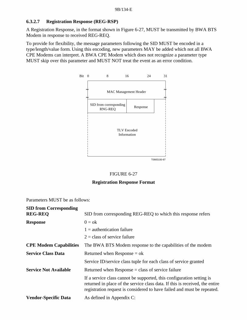
9B/134-E
6.3.2.7 Registration Response (REG-RSP)
A Registration Response, in the format shown in Figure 6-27, MUST be transmitted by BWA BTSModem in response to received REG-REQ.
To provide for flexibility, the message parameters following the SID MUST be encoded in atype/length/value form. Using this encoding, new parameters MAY be added which not all BWACPE Modems can interpret. A BWA CPE Modem which does not recognize a parameter typeMUST skip over this parameter and MUST NOT treat the event as an error condition.
~
~
T0905100-97
~
~MAC Management Header
SID from correspondingRNG-REQ
Bit 0 8 16 24 31
TLV EncodedInformation
Response
FIGURE 6-27
Registration Response Format
Parameters MUST be as follows:
SID from CorrespondingREG-REQ SID from corresponding REG-REQ to which this response refers
Response 0 = ok
1 = authentication failure
2 = class of service failure
CPE Modem Capabilities The BWA BTS Modem response to the capabilities of the modem
Service Class Data Returned when Response = ok
Service ID/service class tuple for each class of service granted
Service Not Available Returned when Response = class of service failure
If a service class cannot be supported, this configuration setting isreturned in place of the service class data. If this is received, the entireregistration request is considered to have failed and must be repeated.
Vendor-Specific Data As defined in Appendix C:

9B/134-E
• Vendor ID Configuration Setting (vendor ID of BWA BTS modem)
• Vendor-specific extensions
NOTE - Service class IDs MUST be those requested in the corresponding REG-REQ.
NOTE - The initialization SID MUST no longer be used once the REG-RSP is received.
6.3.2.7.1 Encodings
The type values used MUST be those shown below. These are unique within the registrationresponse message but not across the entire MAC message set. The type and length fields MUST eachbe 1 octet.
6.3.2.7.1.1 CPE Modem Capabilities
This field defines the BWA BTS Modem response to the CPE modem capability field in theRegistration Request. The BWA BTS Modem responds to the CPE modem capabilities to indicatewhether they may be used. If the BWA BTS Modem does not recognize a CPE modem capability, itmust return this as "off" in the Registration Response.
Only capabilities set to "on" in the REG-REQ may be set "on" in the REG-RSP as this is thehandshake indicating that they have been successfully negotiated.
Encodings are as defined for the Registration Request.
6.3.2.7.1.2 Service Class Data
This encoding defines the parameters associated with a requested class of service. It is somewhatcomplex in that it is composed from a number of encapsulated type/length/value fields. Theencapsulated fields define the particular class of service parameters for the class of service inquestion. Note that the type fields defined are only valid within the encapsulated service class dataconfiguration setting string. A single service class data configuration setting MUST be used to definethe parameters for a single service class. Multiple class definitions MUST use multiple service classdata configuration setting sets.
type length value
1 n encoded service class data
Internal service class data encodings
Class ID
The value of the field MUST specify the identifier for the class of service to which the encapsulatedstring applies. This MUST be a class which was requested in the associated REG-REQ.
type length value
1 1 from REG-REQ
Valid Range
The class ID MUST be in the range 1 to 16.
Service ID
The value of the field MUST specify the SID associated with this service class.
type length value
2 2 SID

9B/134-E
6.3.2.7.2 Registration Response Encoding Example
An example of Registration Response encoding is given in Figure 6-28.
T0905880-97
Service class definition class 1
Service class definition class 2
Service class definition class n
Modem capability
Type1
Length7
Type1
Length7
Type1
Length7
Type6
Length6
FIGURE 6-28
Example of Registration Response Encoding
6.3.2.7.3 Sample Service Class Data Encoding
Sample service class data encodings are provided in Table 6-17.

9B/134-E
TABLE 6-17
Sample Service Class Data Encoding
Type Length VALUE(sub)type
Length Value Description
1 7 service class dataconfiguration setting
1 1 1 service class 1
2 2 123 SID for this class
1 7 service class dataconfiguration setting
1 1 2 service class 2
2 2 244 SID for this class
1 7 service class dataconfiguration setting
1 1 n service class n
2 2 345 SID for this class
6.3.2.8 Upstream Channel Change Request (UCC-REQ)
An Upstream Channel Change Request MAY be transmitted by a BWA BTS Modem to cause aBWA CPE Modem to change the upstream channel on which it is transmitting. The format of anUCC-REQ message is shown in Figure 6-29.
~
~
T0905890-97
~
~
MAC Management Header
Bit 0 8 16 24 31
Upstreamchannel ID
FIGURE 6-29
Upstream Channel Change Request

9B/134-E
Parameters MUST be as follows:
Upstream channel ID
The identifier of the upstream channel to which the BWA CPE Modem is to switch for upstreamtransmissions. This is an 8-bit field.
6.3.2.9 Upstream Channel Change Response (UCC-RSP)
An Upstream Channel Change Response MUST be transmitted by a BWA CPE Modem in responseto a received Upstream Channel Change Request message to indicate that it has received and iscomplying with the UCC-REQ. The format of an UCC-RSP message is shown in Figure 6-30.
Before it begins to switch to a new upstream channel, a BWA CPE Modem MUST transmit a UCC-RSP on its existing upstream channel. A BWA CPE Modem MAY ignore an UCC-REQ messagewhile it is in the process of performing a channel change. When a BWA CPE Modem receives aUCC-REQ message requesting that it switch to an upstream channel that it is already using, theBWA CPE Modem MUST respond with a UCC-RSP message on that channel indicating that it isalready using the correct channel.
To switch to a new upstream channel, a BWA CPE Modem will begin a new ranging procedure forthat channel, and upon completion of ranging will proceed without re-performing registration. Thefull procedure for changing channels is described in Section 7.2.14.
~
~
T0905900-97
~
~
MAC Management Header
Bit 0 8 16 24 31
Upstreamchannel ID
FIGURE 6-30
Upstream Channel Change Response
Parameters MUST be as follows:
Upstream channel ID
The identifier of the upstream channel to which the BWA CPE Modem is to switch for upstreamtransmissions. This is the same Channel ID specified in the UCC-REQ message. This is an 8-bit field.

9B/134-E
6.4 Upstream Bandwidth Allocation
The upstream channel is modelled as a stream of mini-slots. The BWA BTS Modem MUST generatethe time reference for identifying these slots. It MUST also control access to these slots by the BWACPE modems. For example, it MAY grant some number of contiguous slots to a BWA CPE Modemfor it to transmit a data PDU. The BWA CPE Modem MUST time its transmission so that the BWABTS Modem receives it in the time reference specified. This section describes the elements ofprotocol used in requesting, granting, and using upstream bandwidth. The basic mechanism forassigning bandwidth management is the allocation map. Please refer to Figure 6-31.
The allocation map is a MAC Management message transmitted by the BWA BTS Modem on thedownstream channel which describes, for some interval, the uses to which the upstream mini-slotsMUST be put. A given map MAY describe some slots as grants for particular stations to transmitdata in, other slots as available for contention transmission, and other slots as an opportunity for newstations to join the link.
Many different scheduling algorithms MAY be implemented in the BWA BTS Modem by differentvendors; this specification does not mandate a particular algorithm. Instead, it describes the protocolelements by which bandwidth is requested and granted.
BWA CPE tx opportunity
BWA CPE tx opportunity
request contention area
current map previous map
mini-slots
maintenance
permitted use of the upstream channel
transmitted on downstream channel by the BWA BTS Map PDU
as-yet unmapped
time
FIGURE 6-31
Allocation Map

9B/134-E
The bandwidth allocation MUST include the following basic elements:
• Each BWA CPE Modem has one or more short (14-bit) service identifiers as well as a 48-bitaddress.
• Upstream bandwidth is divided into a stream of mini-slots. Each mini-slot is numberedrelative to a master reference maintained by the BWA BTS Modem. The clockinginformation is distributed to the BWA CPE Modems by means of SYNC packets.
• BWA CPE Modems MAY issue requests to the BWA BTS Modem for upstreambandwidth.
The BWA BTS Modem MUST transmit allocation map PDUs on the downstream channel definingthe allowed usage of each mini-slot. The map is described below.
6.4.1 The Allocation Map MAC Management Message
The allocation map is a varying-length MAC Management message that is transmitted by the BWABTS Modem to define transmission opportunities on the upstream channel. It includes a fixed-lengthheader followed by a variable number of information elements (IEs) in the format shown inSection 6.3.2.3. Each information element defines the allowed usage for a range of mini-slots.
The fixed header includes the following (see also Figure 6-18):
• An 8-bit upstream channel identifier. This allows multiple upstream channels to be associatedwith a single downstream channel (Multiple upstream/downstream channel issues MAY be addressedby vendors in a variety of ways, and are beyond the scope of this specification).
• (8 bits) the number of Information Elements which follow.
• (16 bits) reserved for future use.
• The effective start time of the first entry in this map. This is expressed as a 32-bit mini-slotcounter. The time reference is distributed separately by the SYNC PDUs. Note that the Map PDUMUST be transmitted in advance of its effective start time in order to allow BWA CPE Modems toreceive and process it (see Section 6.4.2).
• The latest time for which responses to upstream requests are included in this MAP.
6.4.1.1 Information Elements
Each IE consists of a 14-bit Service ID, a 4-bit type code, and a 14-bit starting offset as defined inSection 6.3.2.3. Since all stations MUST scan all IEs, it is critical that IEs be short and relativelyfixed format. IEs within the map are strictly ordered by starting offset. For most purposes, theduration described by the IE is inferred by the difference between the IE's starting offset and that ofthe following IE. For this reason, a null IE MUST terminate the list. Refer to Table 6-15.
Four types of Service IDs are defined:
1) 0x3FFF - broadcast, intended for all stations.
2) 0x2000-0x3FFE - multicast, purpose is defined administratively. See Appendix A.
3) 0x0001-0x1FFF - unicast, intended for a particular BWA CPE Modem or a particularservice within that BWA CPE Modem.
4) 0x0000 - null address, addressed to no station.
The types of information elements which MUST be supported are defined below.

9B/134-E
6.4.1.1.1 The Request IE
The Request IE provides an upstream interval in which requests MAY be made for bandwidth forupstream data transmission. The character of this IE changes depending on the class of Service ID. Ifbroadcast, this is an invitation for BWA CPE Modems to contend for requests. BWA CPE ModemsMUST choose a random mini-slot within this interval in which to transmit their requests, to reducethe possibility of collisions. If unicast, this is an invitation for a particular BWA CPE Modem torequest bandwidth. Unicasts MAY be used as part of a class-of-service implementation (see below).
6.4.1.1.2 The Request/Data IE
The Request/Data IE provides an upstream interval in which requests for bandwidth or short datapackets MAY be transmitted. This IE is distinguished from the Request IE in that:
• It provides a means by which allocation algorithms MAY provide for "immediate" datacontention under light loads, and a means by which this opportunity can be withdrawn as networkloading increases.
• Multicast Service IDs can be used to specify maximum data length, as well as allowedrandom starting points within the interval. For example, a particular multicast ID MAY specify amaximum of 64-byte data packets, with random starting points of every fourth slot.
A small number of well-known multicast Service IDs are defined in Appendix A. Others are availablefor vendor-specific algorithms.
Since data packets transmitted within this interval may collide, the BWA BTS Modem MUSTacknowledge any that are successfully received. The data packet MUST indicate in the MAC Headerthat a data acknowledgment is desired (see Table 6-12).
6.4.1.1.3 The Initial Maintenance IE
The Initial Maintenance IE provides an interval in which new stations may join the network. A longinterval, equivalent to the maximum round-trip propagation delay plus the transmission time of theRanging Request (RNG-REQ) message (see Section 6.3.2.4), MUST be provided to allow newstations to perform initial ranging.
6.4.1.1.4 The Station Maintenance IE
The Station Maintenance IE provides an interval in which stations are expected to perform someaspect of routine network maintenance, such as ranging or power adjustment. The BWA BTSModem MAY request that a particular BWA CPE Modem perform some task related to networkmaintenance, such as periodic transmit power adjustment. In this case, the Station Maintenance IE isunicast to provide upstream bandwidth in which to perform this task.
6.4.1.1.5 Short and Long Data Grant IEs
The Data Grant IE provides an opportunity for a BWA CPE Modem to transmit one or moreupstream PDUs. These IEs MAY also be used, with a null slot range, to indicate that a request hasbeen received and is pending. This IE is issued either in response to a request from a station, orbecause of an administrative policy providing some amount of bandwidth to a particular station (seeclass-of-service discussion below).

9B/134-E
Short Data Grants are used with intervals less than or equal to the maximum burst size for this usagespecified in the Upstream Channel Descriptor. If Short Data bursts are defined in the UCD, then allLong Data Grants MUST be for a larger number of mini-slots than the maximum for Short Data.The distinction between Long and Short Data Grants may be exploited in physical-layer forward-error-correction coding; otherwise, it is not meaningful to the bandwidth allocation process.
If this IE is a null-interval acknowledgment, it MUST follow all non-null-interval IEs. This allowsBWA CPE modems to process all actual interval allocations first, before scanning the Map forrequest acknowledgements and data acknowledgements.
6.4.1.1.6 Data Acknowledge IE
The Data Acknowledge IE acknowledges that a data PDU was received. The BWA CPE ModemMUST have requested this acknowledgment within the data PDU (normally this would be done forPDUs transmitted within a contention interval in order to detect collisions).
This IE MUST follow all non-null-interval IEs. This allows BWA CPE modems to process all actualinterval allocations first, before scanning the Map for request acknowledgements and dataacknowledgements.
6.4.1.1.7 Expansion IE
The Expansion IE provides for extensibility, if more than 16 code points or 32 bits are needed forfuture IEs.
6.4.1.1.8 Null IE
A Null IE terminates all actual allocations in the IE list. It is used to infer a length for the lastinterval. All data acknowledgements and all null data grants follow the Null IE.
6.4.1.2 Requests
Only one type of upstream request is inherent to the allocation protocol: a request for upstreambandwidth. This request MAY be transmitted any time that either a request or a data PDU is allowedfrom the particular station. It MAY be transmitted during an interval described by any of:
• A Request IE
• A Request/Data IE
• A Data Grant IE.
In addition, it MAY be piggybacked12 on a data transmission. The request includes:
• The Service ID making the request
• The number of mini-slots or ATM cells requested
The number of mini-slots requested MUST be the total number that are desired by the BWA CPEModem at the time of the request, subject to administrative limits13. The BWA CPE Modem MUSTrequest a number of mini-slots corresponding to one or more complete packets. A non-concatenatingBWA CPE Modem MUST request only the necessary mini-slots for one MAC frame per request. If,
____________________12 When piggybacked, these values are carried in the Extended Header (Section 6.2.6,
EH_TYPE = 1).
13 When piggybacked, these values are carried in the Extended Header (Section 6.2.6,EH_TYPE = 1).

9B/134-E
for whatever reason, a previous request has not been satisfied when the BWA CPE Modem ismaking a new request, it MUST include the number of slots from the old request in the new total.Note that only one request at a time (per Service ID) will be outstanding. Because the BWA BTSModem MUST continue to issue null grants for as long as a request is unsatisfied, the BWA CPEModem is able to unambiguously determine when its request is still pending.
Administrative limits MAY be assigned, either globally or per Service ID, on the number of mini-slots that MAY be requested at once. The global limit is configured as the maximum transmissionburst size.
6.4.2 Map Transmission and Timing
The allocation map MUST be transmitted in time to propagate across the physical BWA and bereceived and handled by the receiving BWA CPE Modems . As such, it MAY be transmittedconsiderably earlier than its effective time. The components of the delay are:
• Worst-case round-trip propagation delay - may be network-specific, but on the order ofhundreds of microseconds.
• Queuing delays within the BWA BTS Modem - implementation-specific.
• Processing delays within the BWA CPE Modems - MUST allow a minimum processing timeby each BWA CPE Modem as specified in Appendix B (BWA CPE Modem MAP Processing Time).
• PMD-layer FEC interleaving.
Within these constraints, vendors MAY wish to minimize this delay so as to minimize latency ofaccess to the upstream channel.
The number of mini-slots described MAY vary from map to map. At minimum, a map MAY describea single mini-slot. This would be wasteful in both downstream bandwidth and in processing timewithin the BWA CPE Modems . At maximum, a map MAY stretch to tens of milliseconds. Such amap would provide poor upstream latency. Allocation algorithms MAY vary the size of the mapsover time to provide a balance of network utilization and latency under varying traffic loads.
At minimum, a map MUST contain two Information Elements: one to describe an interval and a nullIE to terminate the list. At a maximum, a map MUST be bounded by a limit of 240 informationelements. Maps are also bounded in that they MUST NOT describe more than 4096 mini-slots intothe future. The latter limit is intended to bound the number of future mini-slots that each BWA CPEModem is required to track. Even though several maps may be outstanding, the sum of the numberof mini-slots they describe MUST NOT exceed 4096.
The set of all maps, taken together, MUST describe every mini-slot in the upstream channel. If aBWA CPE Modem fails to receive a map describing a particular interval, it MUST NOT transmitduring that interval.
Multiple maps MAY be outstanding at once.
6.4.3 Protocol Example
This section illustrates the interchange between the BWA CPE Modem and the BWA BTS Modemwhen the BWA CPE Modem has data to transmit (Figure 6-32). Suppose a given BWA CPEModem has a data PDU available for transmission.

9B/134-E
slots mapped by first Map PDU
Map PDU Map PDU data PDU
BTS modem
CPE modem
Request
second map
t 1
t 2
t 3
t 4
t 5 t 6 t 7
t 8
t 9
t 10
t 11
FIGURE 6-32
Protocol Example
Place a note at the bottom of the page. Footnote 9 does not exist reference Appendix C.
Description
1) At time t1, the BWA BTS Modem transmits a map whose effective starting time is t3. Withinthis map is a Request IE which will start at t5. The difference between t1 and t3 is needed to allowfor:
• downstream propagation delay (including FEC interleaving) to allow all BWA CPE Modemsto receive the Map;
• processing time at the BWA CPE Modem (allows the BWA CPE Modems to parse the Mapand translate it into transmission opportunities);
• upstream propagation delay (to allow the BWA CPE Modem’s transmission of the firstupstream data to begin in time to arrive at the BWA BTS Modem at time t3).
2) At t2, the BWA CPE Modem receives this map and scans it for request opportunities. Inorder to minimize request collisions, it calculates t6 as a random offset from t5 within the intervaldescribed by the Request IE (see Section 6.4.4, also the multicast SID definitions in Appendix A.2).
3) At t4, the BWA CPE Modem transmits a request for as many mini-slots as needed toaccommodate the PDU. Time t4 is chosen based on the ranging offset (see Section 6.3.2.5) so thatthe request will arrive at the BWA BTS Modem at t6.
4) At t6, the BWA BTS Modem receives the request and schedules it for service in the nextmap. (The choice of which requests to grant will vary with the class of service requested, anycompeting requests, and the algorithm used by the BWA BTS Modem.)
5) At t7, the BWA BTS Modem transmits a map whose effective starting time is t9. Within thismap, a data grant for the BWA CPE Modem will start at t11.
6) At t8, the BWA CPE Modem receives the map and scans for its data grant.

9B/134-E
7) At t10, the BWA CPE Modem transmits its data PDU so that it will arrive at the BWA BTSModem at t11. Time t10 is calculated from the ranging offset as in step 3.
Steps 1 and 2 need not contribute to access latency if BWA CPE Modems routinely maintain a list ofrequest opportunities.
At Step 3, the request may collide with requests from other BWA CPE Modems and be lost. TheBWA BTS Modem does not directly detect the collision. The BWA CPE Modem determines that acollision (or other reception failure) occurred when the next map fails to include acknowledgment ofthe request. The BWA CPE Modem MUST then perform a back-off algorithm and retry.
At Step 4, the BWA BTS Modem scheduler MAY fail to accommodate the request within the nextmap. If so, it MUST reply with a zero-length grant in that map. It MUST continue to report thiszero-length grant in all succeeding maps until the request can be granted. This MUST signal to theBWA CPE Modem that the request is still pending. So long as the BWA CPE Modem is receiving azero-length grant, it MUST NOT issue new requests for that service queue.
6.4.4 Contention Resolution
The BWA BTS Modem controls assignments on the upstream channel through the MAP anddetermines which mini-slots are subject to collisions. The BWA BTS Modem MAY allow collisionson either Requests or Data PDUs.
The mandatory method of contention resolution which MUST be supported is based on a truncatedbinary exponential back-off, with the initial back-off window and the maximum back-off windowcontrolled by the BWA BTS Modem. The values are specified as part of the Bandwidth AllocationMap (MAP) MAC message and represent a power-of-two value. For example, a value of 4 indicatesa window between 0 and 15; a value of 10 indicates a window between 0 and 1023.
When a BWA CPE Modem has information to send and wants to enter the contention resolutionprocess, it sets its internal back-off window equal to the initial back-off window defined in the MAPcurrently in effect.
The BWA CPE Modem MUST randomly select a number within its back-off window. This randomvalue indicates the number of contention transmit opportunities which the BWA CPE ModemMUST defer before transmitting. A BWA CPE Modem MUST only consider contention transmitopportunities for which this transmission would have been eligible. These are defined by eitherRequest IEs or Request/Data IEs in the MAP. Note: Each IE can represent multiple transmissionopportunities.
As an example, consider a BWA CPE Modem whose initial back-off window is 0 to 15 and itrandomly selects the number 11. The BWA CPE Modem must defer a total of 11 contentiontransmission opportunities. If the first available Request IE is for 6 requests, the BWA CPE Modemdoes not use this and has 5 more opportunities to defer. If the next Request IE is for 2 requests, theBWA CPE Modem has 3 more to defer. If the third Request IE is for 8 requests, the BWA CPEModem transmits on the fourth request, after deferring for 3 more opportunities.
After a contention transmission, the BWA CPE Modem waits for a Data Grant (Data Grant Pending)or Acknowledgment in a subsequent MAP. Once either is received, the contention resolution iscomplete. The BWA CPE Modem determines that the contention transmission was lost when it findsa MAP without a Data Grant (Data Grant Pending) or Acknowledgment for it and with an Ack timemore recent than the time of transmission. The BWA CPE Modem MUST now increase its back-offwindow by a factor of two, as long as it is less than the maximum back-off window. The BWA CPE

9B/134-E
Modem MUST randomly select a number within its new back-off window and repeat the deferringprocess described above.
This re-try process continues until the maximum number of retries (16) has been reached, at whichtime the PDU MUST be discarded. NOTE - The maximum number of retries is independent of theinitial and maximum back-off windows that are defined by the BWA BTS Modem.
If the BWA CPE Modem receives a unicast Request or Data Grant at any time while deferring forthis SID, it MUST stop the contention resolution process and use the explicit transmit opportunity.
The BWA BTS Modem has much flexibility in controlling the contention resolution. At one extreme,the BWA BTS Modem MAY choose to set up the initial and maximum back-off windows to emulatean Ethernet-style back-off with its associated simplicity and distributed nature, but also its fairnessand efficiency issues. This would be done by setting initial = 0 and max = 10 in the UpstreamChannel Descriptor. At the other end, the BWA BTS Modem MAY make the initial and maximumback-off windows identical and frequently update these values in the MAP so all BWA CPE modemsare using the same, and hopefully optimal, back-off window.
6.4.5 BWA CPE Modem Behaviour
The following rules govern the response a BWA CPE Modem may make when processing maps:
1) A BWA CPE Modem MUST first use any Grants assigned to it. Next, the BWA CPEModem MUST use any unicast REQ for it. Finally, the BWA CPE Modem MUST use then nextavailable broadcast/multicast REQ or REQ/Data IEs for which it is eligible.
2) Only one Request may be outstanding at a time for a particular Service ID.
3) If a BWA CPE Modem has a Request pending, it MUST NOT use intervening contentionintervals for that Service ID.
6.4.6 Support for Multiple Channels
Vendors MAY choose to offer various combinations of upstream and downstream channels withinone MAC service access point. The upstream bandwidth allocation protocol allows for multipleupstream channels to be managed via one or many downstream channels.
If multiple upstream channels are associated with a single downstream channel, then the BWA BTSModem MUST send one allocation map per upstream channel. The map's channel identifier, takenwith the Upstream Channel Descriptor Message (see Section 6.3.2.2), MUST specify to whichchannel each map applies. There is no requirement that the maps be synchronized across channels.Appendix G provides an example.
If multiple downstream channels are associated with a single upstream channel, the BWA BTSModem MUST ensure that the allocation map reaches all BWA CPE Modems . That is, if someBWA CPE Modems are attached to a particular downstream channel, then the map MUST betransmitted on that channel. This MAY necessitate that multiple copies of the same map betransmitted. The slot reference in the map header MUST always relate to the SYNC reference on thedownstream channel on which it is transmitted.
If multiple downstream channels are associated with multiple upstream channels, the BWA BTSModem MAY need to transmit multiple copies of multiple maps to ensure both that all upstreamchannels are mapped and that all BWA CPE Modems have received their needed maps.

9B/134-E
6.4.7 Classes of Service
This specification does not provide explicit classes of service, but provides the means for vendors toprovide a variety of types of service.
This section illustrates how the available mechanisms can be used to provide support for the serviceclasses defined in RFC-1633 "Integrated Services in the Internet Architecture: An Overview".
RFC-1633 divides applications into elastic applications which will always wait for data to arrive andinelastic applications in which the data must arrive within a certain time to be useful.
Within the inelastic category further sub divisions can be defined:
• delay-intolerant - the data must arrive within a perfectly reliable upper bound on delay;
• delay-tolerant - the data must arrive within a fairly reliable but not perfectly reliable delaybound.
Within the elastic category the following application types can be distinguished:
• interactive burst;
• interactive bulk.
The service model should be able to support both types of inelastic application and to allow forlower delays for interactive elastic applications than for bulk elastic applications.
Inelastic Delay-Intolerant - The BWA BTS Modem provides a Data Grant of fixed size to aconfigured Service ID once every N mini-slots. This Service ID MAY be assigned to all traffic for aBWA CPE modem, or it MAY only be used for this particular service within the BWA CPE modem.
Inelastic Delay-Tolerant - The BWA BTS Modem periodically provides a unicast Request IE to aconfigured Service ID. It then grants the request based on the negotiated delay variation, bandwidth,and other considerations. The BWA CPE Modem has guaranteed access in which to make requests,and the BWA BTS Modem’s scheduling algorithm provides the negotiated service. As an alternative,the minimum data rate of the service negotiation MAY be provided in the same way that inelasticdelay-intolerant traffic is handled.
Elastic Application Support - is provided by a contention/FIFO service strategy, in which BWACPE Modems contend for request slots, and the BWA BTS Modem services requests as they arrive.Service priorities can allow differential delays between interactive and bulk applications.
6.4.7.1 Resource-Sharing
In order to support multiple end systems sharing the same upstream and downstream links, it isnecessary to provide resource-sharing mechanisms for the link bandwidth. The following are someexamples of this:
Link-usage feedback is provided implicitly by contention and by the BWA BTS Modem’sscheduling algorithm, so no explicit congestion notifications are needed.
Guaranteed Minimum Bit Rate can be provided in much the same manner as inelastic delay-tolerantapplication support.
Guaranteed Maximum Bit Rate MAY be provided by a number of implementation mechanisms,including the BWA BTS Modem’s allocation algorithm and throttling within the BWA CPE Modem.
Service Priorities MUST be implemented by applying different service criteria to different ServiceIDs. It is anticipated that a particular BWA CPE Modem MAY have several Service IDs, each

9B/134-E
corresponding to a particular service class. The particular services offered MAY vary from vendor tovendor.
Contention that is limited to a service class MAY be accomplished with multicast Request IEs andRequest/Data IEs. Creation of such multicast groups is vendor-specific.
6.5 Timing and Synchronization
One of the major challenges in designing a MAC protocol for a BWA network is compensating forthe large delays involved. These delays are an order of magnitude larger than the transmission bursttime in the upstream. To compensate for these delays, the BWA CPE modem MUST be able to timeits transmissions precisely to arrive at the BWA BTS Modem at the start of the assigned mini-slot.
To accomplish this, two pieces of information are needed by each BWA CPE modem:
• a global timing reference sent downstream from the BWA BTS Modem to all BWA CPEmodems;
• a timing offset, calculated during a ranging process, for each BWA CPE modem.
6.5.1 Global Timing Reference
The BWA BTS Modem MUST create a global timing reference by transmitting the TimeSynchronization (SYNC) MAC management message downstream at precise times. The messagecontains a timestamp that exactly identifies when the BWA BTS Modem transmitted the message.BWA CPE modems MUST then compare the actual time the message was received with thetimestamp and adjust their local clock references accordingly.
The SYNC message MUST be transmitted on a periodic basis called the MAC SYNC Interval(MSI). The BWA BTS Modem MUST transmit one SYNC message within each MSI. The BWABTS Modem determines when to send the SYNC message based on the requirements of this andother downstream traffic. The maximum separation between any SYNC messages is therefore 2 MSIperiods.
The Transmission Convergence sublayer must operate closely with the MAC sublayer to provide anaccurate timestamp for the SYNC message. As mentioned in the Ranging section below(Section 6.5.3), the model assumes that the timing delays through the remainder of the PHY layerMUST be relatively constant. Any variation in the PHY delays MUST be accounted for in the guardtime of the PHY overhead.
It is intended that the MAC Sync Interval be on the order of tens of milliseconds. This imposes verylittle downstream overhead while letting BWA CPE modems acquire their global timingsynchronization quickly.
6.5.2 BWA CPE Modem Channel Acquisition
Any BWA CPE modem MUST NOT use the upstream channel until it has successfully synchronizedto the downstream.
First, the BWA CPE modem MUST establish PMD sublayer synchronization. This implies that it haslocked onto the correct frequency, equalized the downstream channel, recovered any PMD sublayerframing and the FEC is operational (refer to Section 7.2.1). At this point, a valid bit stream is beingsent to the transmission convergence sublayer. The transmission convergence sublayer performs itsown synchronization (see Section 5). On detecting the well-known BWA PID, along with a payloadunit start indicator per ITU-T H.222.0, it delivers the MAC frame to the MAC sublayer.

9B/134-E
The MAC sublayer MUST now search for the Timing Synchronization (SYNC) MAC managementmessages. The BWA CPE modem achieves MAC synchronization once it has received at least twoSYNC messages within the maximum SYNC interval (see Appendix B) and has verified that its clocktolerances are within specified limits.
A BWA CPE modem remains in "SYNC" as long as it continues to successfully receive the SYNCmessages. If the Lost SYNC Interval (see Appendix B) has elapsed without a valid SYNC message,a BWA CPE modem MUST NOT use the upstream and MUST try to re-establish synchronizationagain.
6.5.3 Ranging
Ranging is the process of acquiring the correct timing offset such that the BWA CPE modem'stransmissions are aligned to the correct mini-slot boundary. The timing delays through the PHY layerMUST be relatively constant. Any variation in the PHY delays MUST be accounted for in the guardtime of the upstream PMD overhead.
First, a BWA CPE modem MUST synchronize to the downstream and learn the upstream channelcharacteristics through the Upstream Channel Descriptor MAC management message. At this point,the BWA CPE modem MUST scan the Bandwidth Allocation MAP message to find a StationMaintenance region assigned to initializing BWA CPE Modems . Refer to Section 6.4.1.1.4. TheBWA BTS Modem MUST make a Station Maintenance region large enough to account for thevariation in delays between any two BWA CPE Modems .
The BWA CPE modem MUST put together a Ranging Request message to be sent in the StationMaintenance region. The SID field MUST be set to the non-initialized BWA CPE Modem value(zero).
Ranging adjusts each BWA CPE Modem’s timing offset such that it appears to be located right nextto the BWA BTS Modem. The BWA CPE Modem MUST set its initial timing offset to the amountof internal fixed delay equivalent to putting this BWA CPE Modem next to the BWA BTS Modem.This amount includes delays introduced through a particular implementation, and MUST include thedownstream PHY interleaving latency.
When the Station Maintenance transmit opportunity occurs, the BWA CPE modem MUST send theRanging Request message. Thus, the BWA CPE modem sends the message as if it was physicallyright at the BTS Modem.
Once the BWA BTS Modem has successfully received the Ranging Request message, it MUSTreturn a Ranging Response message addressed to the individual BWA CPE modem. Within theRanging Response message MUST be a temporary SID assigned to this BWA CPE modem until ithas completed the registration process. The message MUST also contain information on RF powerlevel adjustment and offset frequency adjustment as well as any timing offset corrections.
The BWA CPE modem MUST now wait for an individual Station Maintenance region assigned to itstemporary SID. It MUST now transmit a Ranging Request message at this time using the temporarySID along with any power level and timing offset corrections.

9B/134-E
The BWA BTS Modem MUST return another Ranging Response message to the BWA CPE modemwith any additional fine tuning required. The ranging request/response steps MUST be repeated untilthe response contains a Ranging Successful notification. At this point, the BWA CPE modem MUSTjoin normal data traffic in the upstream. See Section 7 for complete details on the entire initializationsequence. In particular, state machines and the applicability of retry counts and timer values for theranging process are defined in Section 6.2.4.
NOTE - The burst type to use for any transmission is defined by the Interval Usage Code (IUC).Each IUC is mapped to a burst type in the UCD message.
6.5.4 Timing Units and Relationships
The SYNC message conveys a time reference that is measured in 6.25-microsecond ticks. Theseunits were chosen as the greatest-common-divisor of the upstream mini-slot time across variousmodulations and symbol rates. As this is decoupled from particular upstream channel characteristics,a single SYNC time reference may be used for all upstream channels associated with the downstreamchannel.
The bandwidth allocation MAP uses time units of "mini-slots". A mini-slot represents the byte-timeneeded for transmission of a fixed number of bytes. The size of the mini-slot, expressed as a multipleof the SYNC time reference, is carried in the Upstream Channel Descriptor. The example in Table6-18 relates mini-slots to the SYNC time ticks:
TABLE 6-18
Example Relating Mini-Slots to Time Ticks
Parameter Example Value
Time tick 6.25 microseconds
Mini-slots/second 40 000
Microseconds/mini-slot
25
Ticks/mini-slot 4
The reader is encouraged to try other symbol rates and modulations. Note that the symbols/byte is acharacteristic of an individual burst transmission, not of the channel.
A "mini-slot" is the unit of granularity for upstream transmission opportunities. There is noimplication that any PDU can actually be transmitted in a single mini-slot.
The MAP counts mini-slots in a 32-bit counter that counts to (232 - 1) and then wraps back to zero.The least-significant bits of the mini-slot counter MUST match the most-significant bits of the SYNCcounter. That is, mini-slot N begins at time reference (N * T), where T is the UCD multiplier (T isalways a power of 2).
Note that the constraint that the UCD multiplier be a power of two has the consequence that thenumber of bytes per mini-slot must also be a power of two.

9B/134-E
6.6 Data Link Encryption Support
The procedures to support data link encryption are defined in MCNS2 and MCNS814. Theinteraction between the MAC layer and the security system is limited to the items defined below.
6.6.1 MAC Messages
MAC management messages (Section 6.3) MUST NOT be encrypted.
6.6.2 Framing
Security information is carried as payload data to the MAC and is essentially transparent. A framecarrying an encrypted payload MUST be constructed as shown in Figure 6-33.
BWA MAC Header
Destination MAC Address
Source MAC Address
Security Header as defined in [MCNS2]
Encrypted data
CRC
FIGURE 6-33
Security Framing
The following rules MUST be followed when the encrypted frame is constructed:
• The DLE flag in the FC field of the MAC Header MUST be set.
• The security header MUST follow the MAC source address, and MUST precede thetype/length field.
• The security header will be a multiple of 4 bytes to optimize alignment.
• The message payload must be encrypted and decrypted using the mechanism defined in thefollowing steps.
This example is defined for a frame received by a BWA CPE Modem at the CPE Modem to CPIinterface and transferred over the BWA network to the BWA BTS Modem and forwarded via anEthernet based NSI. For frames travelling in the NSI-to- CPE Modem to CPI interface direction, theroles of BWA CPE Modem and BWA BTS Modem are reversed.
____________________
14 See Appendix A

9B/134-E
6.6.2.1 CPE Modem to CPI interface to RF
Please refer to Figure 6-34.
SA CRC Plain text payload
DA SA Plain text payload
DA SA Encrypted payload SecHdr
DA SA Encrypted payload
DA SA Encrypted payload SecHdr CRC
1)
2)
3)
4)
5)
DA SA Encrypted payload SecHdr CRC 6)
DA
BWA MAC Hdr
FIGURE 6-34
Example of Security Framing at the BWA CPE modem
1) BWA CPE Modem receives frame from Ethernet.
2) Check and discard Ethernet CRC.
3) Encrypt payload.
4) Add Security Header.
5) Calculate new CRC over DA, SA, Security Header and encrypted payload.
6) Add BWA MAC Header and forward on to the RF transmitter.

9B/134-E
6.6.2.2 RF to BWA BTS-NSI
Please refer to Figure 6-35.
CRC
Plain text payload
DA SA Encrypted payload SecHdr
DA Encrypted payload
DA SA Encrypted payload SecHdr CRC 1)
2)
3)
4)
5) DA SA Plain text payload
BWA MAC Hdr
SA
DA SA
FIGURE 6-35
Example of Security Framing at the BWA BTS
1) Check and discard MAC Header.
2) Check and discard CRC.
3) Remove Security Header.
4) Decrypt Payload.
5) Recalculate CRC and forward frame to BTS-NSI.7 BWA CPE modem - BWA BTS Modem Interaction
This section covers key requirements for interaction between the BWA CPE modem and BWA BTSModem. The interaction can be broken down into five basic categories: modem initialization,authentication, configuration, authorization, and signalling.
7.1 BWA BTS Modem Initialization
The mechanism utilized for BWA BTS Modem initialization (local terminal, file download, SNMP,etc.) is described in MCNS515. It MUST meet the following criteria for system interoperability:
• the BWA BTS Modem MUST be able to reboot and operate in a stand-alone mode usingconfiguration data retained in non-volatile storage;
• if valid parameters are not available from non-volatile storage or via another mechanismsuch as the Spectrum Management System (see SMS), the BWA BTS Modem MUST not generateany downstream messages (including SYNC). This will prevent BWA CPE Modems fromtransmitting;
____________________
15 See Appendix A

9B/134-E
• the BWA BTS Modem MUST provide the information defined in Section 6 to BWA CPEModems for each upstream channel.
7.2 BWA CPE modem Initialization
The procedure for initialization of a BWA CPE modem MUST be as shown in Figure 7-1. Thisfigure shows the overall flow between the stages of initialization in a BWA CPE Modem. This showsno error paths, and is simply to provide an overview of the process. The more detailed finite statemachine representations of the individual sections (including error paths) are shown in thesubsequent figures. Timeout values are defined in Appendix B.
The procedure can be divided into the following phases:
• scan for downstream channel and establish synchronization with the BWA BTS Modem;
• obtain transmit parameters (from UCD message);
• perform ranging;
• establish IP connectivity;
• establish time of day;
• establish security association;
• transfer operational parameters.
Each BWA CPE Modem contains the following information when shipped from the manufacturer:
• a unique IEEE 802 48-bit MAC address which is assigned during the manufacturing process.This is used to identify the modem to the various provisioning servers during initialization;
• security information as defined in MCNS2 and MCNS816 (e.g. X.509 certificate) used toauthenticate the BWA CPE Modem to the security server and authenticate the responses from thesecurity and provisioning servers.
The SDL (Specification and Description Language) notation used in the following figures is shownin Figure 7-2 (refer to ITU-T Recommendation Z.100 ITU-T Z.100).
____________________
16 See Appendix A

9B/134-E
Scan for Downstream
Channel
Downstream Sync
Established
Obtain Upstream
Parameters
Upstream Parameters Acquired
Ranging & Automatic
Adjustments
IP Complete
Establish IP
Connectivity
Ranging & Auto Adj Complete
Establish Time of
Day
Time of Day Established
Establish Security
Security Established
Transfer Operational Parameters
Transfer Complete
Register with
BTS modem
Registration Complete
Operational
FIGURE 7-1
BWA CPE Modem Initialization Overview

9B/134-E
T0905160-97
State symbol
Input symbols
Internal
External
Task symbol
Output symbols
Internal
External
Decision symbol
FIGURE 7-2
SDL Notation
7.2.1 Scanning and Synchronization to Downstream
On initialization or after signal loss, the BWA CPE modem MUST acquire a downstream channel.The BWA CPE Modem MUST have non-volatile storage in which the last operational parametersare stored and MUST first try to re-acquire this downstream channel. If this fails, it MUST begin tocontinuously scan the RF channels of the downstream frequency band of operation until it finds avalid downstream signal.
A downstream signal is considered to be valid when the modem has achieved the following steps:
• synchronization of the QAM symbol timing;
• synchronization of the FEC framing;
• synchronization of the MPEG packetization;
• recognition of SYNC downstream MAC messages.

9B/134-E
While scanning, it is desirable to give an indication to the user that the BWA CPE Modem is doingso.
7.2.2 Obtain Upstream Parameters
Refer to Figure 7-3 after synchronization, the BWA CPE Modem MUST wait for an upstreamchannel descriptor message (UCD) from the BWA BTS Modem in order to retrieve transmissionparameters from the data stream. These messages are transmitted periodically from the BWA BTSModem for all available upstream channels and are addressed to the MAC broadcast address. TheBWA CPE Modem MUST determine whether it can use the upstream channel from the channeldescription parameters. If the channel is not suitable, then the BWA CPE Modem MUST wait for achannel description message for a channel which it can use. If no channel can be found after asuitable timeout period, then the BWA CPE Modem MUST continue scanning to find anotherdownstream channel.
When the BWA CPE modem finds an upstream channel with acceptable transmission parameters, itMUST extract the parameters for this upstream from the UCD. It then MUST wait for the nextSYNC message17 and extract the upstream mini-slot timestamp from this message. The BWA CPEModem then MUST wait for a bandwidth allocation map for the selected channel. It MAY thenbegin transmitting upstream in accordance with the MAC operation and the bandwidth allocationmechanism.
It is desirable to give an indication to the user that the BWA CPE Modem has finished searching andhas detected a valid downstream signal and upstream channel.
____________________
17 Alternatively, since the SYNC message applies to all upstream channels, the BWA CPE Modemmay have already acquired a time reference from previous SYNC messages. If so, it need not waitfor a new SYNC.

9B/134-E
T0905170-97
TimeoutT1
Wait forusableUCD
Goodupstreamdescriptor
ScanningWait forSYNC
Extract upstreammini-slotTiming
Wait formap for this
channel
Map forselectedchannel
Ranging
Sync
FIGURE 7-3
Obtaining Upstream Parameters
7.2.3 Message Flows During Scanning and Upstream Parameter Acquisition
The BWA BTS Modem MUST generate SYNC and UCD messages on the downstream at periodicintervals within the ranges defined in Section 6. These messages are addressed to all BWA CPEModems . Refer to Figure 7-4.

9B/134-E
BWA BTS Modem BWA CPE Modem
clock time to send SYNC ----------------SYNC-----------------> |clock time to send UCD ----------------UCD-------------------> |
|
clock time to send SYNC ----------------SYNC-----------------> || Example of a UCD cycle| prior to BWA CPE Modem power-on|
clock time to send SYNC ----------------SYNC-----------------> |||
clock time to send SYNC ----------------SYNC-----------------> |||
clock time to send SYNC ----------------SYNC----------------->clock time to send UCD ----------------UCD------------------->
clock time to send SYNC ----------------SYNC----------------->power on sequence complete
clock time to send SYNC ----------------SYNC----------------->establish PHY synchronizationand wait for UCD
clock time to send SYNC ----------------SYNC----------------->
clock time to send SYNC ----------------SYNC----------------->clock time to send UCD ----------------UCD------------------->
obtain parameters for this upstreamchannel to use for initialization
clock time to send SYNC ----------------SYNC----------------->extract slot info for upstream andwait for transmit opportunity toperform ranging
clock time to send SYNC ----------------SYNC----------------->
clock time to send MAP ----------------MAP------------------>start ranging process
FIGURE 7-4
Message Flows During Scanning and Upstream Parameter Acquisition
7.2.4 Ranging and Automatic Adjustments
The ranging and adjustment process is fully defined in Section 6 and in the following sections. Themessage sequence chart and the finite state machines on the following pages define the ranging and
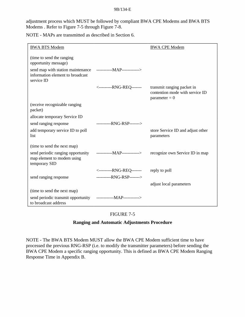
9B/134-E
adjustment process which MUST be followed by compliant BWA CPE Modems and BWA BTSModems . Refer to Figure 7-5 through Figure 7-8.
NOTE - MAPs are transmitted as described in Section 6.
BWA BTS Modem BWA CPE Modem
(time to send the rangingopportunity message)
send map with station maintenanceinformation element to broadcastservice ID
-----------MAP------------>
<---------RNG-REQ------- transmit ranging packet incontention mode with service IDparameter = 0
(receive recognizable rangingpacket)
allocate temporary Service ID
send ranging response ----------RNG-RSP------->
add temporary service ID to polllist
store Service ID and adjust otherparameters
(time to send the next map)
send periodic ranging opportunitymap element to modem usingtemporary SID
-----------MAP------------> recognize own Service ID in map
<---------RNG-REQ------- reply to poll
send ranging response ----------RNG-RSP------->
adjust local parameters
(time to send the next map)
send periodic transmit opportunityto broadcast address
------------MAP----------->
FIGURE 7-5
Ranging and Automatic Adjustments Procedure
NOTE - The BWA BTS Modem MUST allow the BWA CPE Modem sufficient time to haveprocessed the previous RNG-RSP (i.e. to modify the transmitter parameters) before sending theBWA CPE Modem a specific ranging opportunity. This is defined as BWA CPE Modem RangingResponse Time in Appendix B.

9B/134-E
T0905180-97
Y
N
Timeout T2
Wait for broadcastmaintenanceopportunity
ErrorRe-initialize MAC
Map withmaintenanceopportunity
SendRNG-REQ
Wait forRNG-RSP
Timeout T3
Adjust localparameters per
RNG-RSP
Retriesexhausted
?
ErrorRe-initialize MAC
Adjustlocal power
Wait for unicastmaintenanceopportunity
Randombackoff
(NOTE)
Wait forbroadcast ranging
opportunity
RNG-RSP
NOTE - Timeout T3 may occur because the RNG-REQs from multiple modems collided. To avoid these modems repeatingthe loop in lockstep, a random backoff is required. This is a backoff over the ranging window specified in the UCD.
FIGURE 7-6
Initial Ranging - BWA CPE Modem

9B/134-E
Yes
No
Time out T4
Wait for unicast maintenance opportunity
Error Re-initialize MAC
Map with mainten ance opportunity
Send RNG-REQ
Wait for RNG-RSP
Time out T3
Adjust local parameters per
RNG-RSP
Retries exhausted
?
Error Re-initialize MAC
Adjust local power
Wait for broadcast ranging
opportunity
RNG-RSP
Establish IP layer
Success set from BTS?
(NOTE 1)
Abort Ranging set from BTS?
Error: Re-initialize MAC
Enable data transfer
No
Yes
Yes
No
NOTE - Ranging Request is within the tolerance of the BTS.
FIGURE 7-7
Initial Ranging - BWA CPE Modem (continued)

9B/134-E
Yes
No
No
No Yes No
Yes Yes
Wait for recognizable RNG-REQ
SID assigned to this CPE
modem already?
Assign temporary SID
Reset retry count in poll list for this
CPE modem
Add CPE modem to poll list for future
maps
Send RNG- RSP
Map will be sent per allocation algorithm
Wait for polled RNG-REQ
RNG-REQ not received
Remove CPE modem from poll list
Wait for recognizable RNG-REQ
Good Enough? (NOTE 1)
Remove CPE modem
from poll list
Send RNG-RSP ( continue)
Wait for polled RNG-REQ
Send RNG-RSP
( abort)
RNG-REQ
RNG-REQ
Retries Exhausted?
Send RNG-RSP ( success)
Retries Exhausted?
Done
NOTE 1 - Means ranging is within the tolerable limits of the BTS.
FIGURE 7-8
Initial Ranging – BWA BTS modem
Ranging Parameter Adjustment
Adjustment of local parameters (e.g. transmit power) in a BWA CPE Modem as a result of thereceipt (or non-receipt) of an RNG-RSP is considered to be implementation-dependent with thefollowing restrictions (refer to Section 6.2.7):
• all parameters MUST be within the approved range at all times;

9B/134-E
• power adjustment MUST start from the minimum value unless a valid power is availablefrom non-volatile storage, in which case this MUST be used as a starting point;
• power adjustment MUST be capable of being reduced or increased by the specified amountin response to RNG-RSP messages;
• if power is adjusted to the maximum value it MUST wrap back to the minimum.
7.2.5 Establish IP Connectivity
At this point, the BWA CPE Modem MUST invoke DHCP mechanisms (RFC-1541) in order toobtain an IP address and any other parameters needed to establish IP connectivity. The DHCPresponse MUST contain the name of a file which contains further configuration parameters. Refer toFigure 7-9.
BWA CPE Modem DHCP
send DHCP request tobroadcast address
----------------DHCP discover------------>
check BWA CPEModem MAC addressand respond
<--------------DHCP offer -----------------
choose server
----------------DHCP request------------->
process request
<--------------DHCP response--------------
set up IP parametersfrom DHCP response
FIGURE 7-9
Establishing IP Connectivity
7.2.6 Establish Time of Day
The BWA CPE Modem and BWA BTS Modem need to have the current date and time. This neednot be authenticated and need only be accurate to the nearest second (MCNS218).
This is required for:
• time-stamping logged events which can be retrieved by the management system;
• key management by the security system.
The protocol by which the time of day is retrieved will be as defined in RFC-868. Refer to Figure 7-10.
____________________
18 See Appendix A

9B/134-E
The request and response will be transferred using UDP.
The time retrieved from the server (UTC) will be combined with the time offset received from theDHCP response to create the current local time.
BWA CPE Modem Time Server
send request to timeserver
----------------time of day request------------>
process request
<--------------time of day response--------------
set up/correct timeof day fromresponse
FIGURE 7-10
Establishing Time of Day
7.2.7 Establish Security Association
If security is required on the network and no security association has been established, the BWACPE Modem MUST establish a security association at this point. The IP address of the securityserver (or servers) MUST be provided as part of the DHCP response. The procedures required arefully defined in MCNS219.
7.2.8 Transfer Operational Parameters
After the DHCP and security association operations are successful, the modem MUST download theparameter file using TFTP, as shown in Figure 7-11. The TFTP configuration parameter server isspecified by the "siaddr" field of the DHCP response.
The parameter fields required in the DHCP response and the format and content of the configurationfile MUST be as defined in Appendix C. Note that these fields are the minimum required forinteroperability.
7.2.9 Registration
A BWA CPE Modem MUST be authorized to forward traffic into the network once it is initialized,authenticated and configured. Refer to Figure 7-11.
The configuration parameters downloaded to the BWA CPE Modem MUST include a networkaccess control object (see Appendix C Section C.8.5). If this is set to "no forwarding", the BWACPE Modem MUST not forward data to the network. It MUST respond to network managementrequests. This allows the BWA CPE Modem to be configured in a mode in which it is manageablebut will not forward data.
____________________
19 See Appendix A

9B/134-E
The BWA CPE Modem MUST forward the operational parameters to the BWA BTS Modem aspart of a registration request. The BWA BTS Modem MUST perform the following operations toconfirm the BWA CPE Modem authorization:
• check the MAC and the authentication signature on the parameter list;
• build a profile for the modem based on the standard configuration settings (see Appendix C);
• assign a service ID based on the classes of service supported;
• reply to the modem registration request.
Vendor-specific configuration settings MUST be ignored (except for inclusion in messageauthorization code calculation).
BWA CPEModem
BWA BTS Modem TFTP
Server
requestparameterfile
------------------------ ----TFTP REQ----- ------------------->
processrequest
<----------------------- --- TFTP RSP---- --------------------
set upoperationalparameters
inform BWABTS Modem
---REG-REQ-->
provision modem
<---REG-RSP--
set upService IDs
FIGURE 7-11
Transferring Operational Parameters and Registration
7.2.10 Service IDs During BWA CPE Modem Initialization
After completion of the Registration process (Section 7.2.9), the BWA CPE Modem will have beenassigned Service IDs (SIDs) to match its class of service provisioning. However, the BWA CPEModem must complete a number of protocol transactions prior to that time (e.g. Ranging, DHCP,etc.), and requires a temporary Service ID in order to complete those steps.
On reception of an Initial Ranging Request, the BWA BTS Modem MUST allocate a temporary SIDand assign it to the BWA CPE Modem for initialization use. The BWA BTS Modem MAY monitor

9B/134-E
use of this SID and restrict traffic to that needed for initialization. It MUST inform the BWA CPEModem of this assignment in the Ranging Response.
On receiving a Ranging Response addressed to it, the BWA CPE Modem MUST use the assignedtemporary SID for further initialization transmission requests until the Registration Response isreceived.
It is possible that the Ranging Response may be lost after transmission by the BWA BTS modem.The BWA CPE Modem MUST recover by timing out and re-issuing its Initial Ranging Request.Since the BWA CPE Modem is uniquely identified by the source MAC address in the RangingRequest, the BWA BTS Modem MAY immediately re-use the temporary SID previously assigned. Ifthe BWA BTS Modem assigns a new temporary SID, it MUST make some provision for aging outthe old SID that went unused (see Section 6.3.2.7).
When assigning class-of-service-provisioned SIDs on receiving a Registration Request, the BWABTS Modem may re-use the temporary SID, assigning it to one of the class of service classesrequested. If so, it MUST continue to allow initialization messages on that SID, since theRegistration Response could be lost in transit. If the BWA BTS Modem assigns all-new SIDs forclass-of-service provisioning, it MUST age out the temporary SID. The aging-out MUST allowsufficient time to complete the registration process in case the Registration Response is lost intransit.
7.2.11 Multiple-Channel Support
In the event that more than one downstream signal is present in the system, the BWA CPE ModemMUST operate using the first valid downstream signal that it encounters when scanning. It will beinstructed via the parameters in the configuration file (see Appendix C) to shift operation to differentdownstream and/or upstream frequencies if necessary.
Both upstream and downstream channels MUST be identified where required in MAC managementmessages using channel identifiers.
7.2.12 Remote RF Signal Level Adjustment
RF signal level adjustment at the BWA CPE Modem is performed through a periodic maintenancefunction using the RNG-REQ and RNG-RSP MAC messages. This is similar to initial ranging and isshown in Figure 7-12 and Figure 7-13. On receiving a RNG-RSP, the BWA CPE Modem MUSTNOT transmit until the RF signal has been adjusted in accordance with the RNG-RSP and hasstabilized (refer to Section 4).

9B/134-E
T0905210- 97
Yes
No
RNG-REQ
No
Yes
Done
Yes
Done
No
Retries Exhausted?
Retries Exhausted?
On periodic timer add CPE modem to poll list
for future maps
Wait for polled RNG-REQ
Map will be sent per allocation algorithm
RNG-REQ not received
Good Enough? (NOTE 1)
Send RNG-RSP (success)
Send RNG-RSP
(abort)
Remove CPE modem from poll list
Destroy SIDs associated with
this CM
Send RNG-RSP (continue)
Wait for polled RNG-REQ
Remove CPE Modem from poll list
NOTE 1 - Means Ranging Request is within the tolerance limits of the BTS modem for power and transmit equalization (if supported).
FIGURE 7-12
Periodic Ranging – BTS Modem

9B/134-E
Unicast maintenance opportunity
Abort Ranging from BTS Modem?
Error Re-initialize MAC
Adjust local parameters per
RNG-RSP
Send RNG-REQ
Operational
RNG-RSP
FIGURE 7-13
Periodic Ranging - BWA CPE Modem View
7.2.13 Changing Upstream Burst Parameters
Whenever the BWA BTS Modem is to change any of the upstream burst characteristics, it mustprovide for an orderly transition from the old values to the new values by all BWA CPE Modems .Whenever the BWA BTS Modem is to change any of the upstream burst values, it MUST:
• Announce the new values in an Upstream Channel Descriptor message. The ConfigurationChange Count field must be incremented to indicate that a value has changed.
After transmitting one or more UCD messages with the new value, the BWA BTS Modem transmitsa MAP message with a UCD Count matching the new Configuration Change Count. The firstinterval in the MAP MUST be a data grant of at least 1 millisecond to the null Service ID (zero).That is, the BWA BTS Modem MUST allow one millisecond for BWA CPE modems to change theirPMD sublayer parameters to match the new set. This millisecond is in addition to other MAP timingconstraints (see Section 6.4.2).
• The BWA BTS Modem MUST NOT transmit MAPs with the old UCD Count aftertransmitting the new UCD.
The BWA CPE Modem MUST use the parameters from the UCD corresponding to the MAP's"UCD Count" for any transmissions it makes in response to that MAP. If the BWA CPE Modemhas, for any reason, not received the corresponding UCD, it cannot transmit during the intervaldescribed by that MAP.

9B/134-E
7.2.14 Changing Upstream Channels
At any time after registration, the BWA BTS Modem MAY direct the BWA CPE Modem to changeits upstream channel. This may be done for traffic balancing, noise avoidance, or any of a number ofother reasons which are beyond the scope of this specification. Figure 7-14 shows the procedure thatMUST be followed by the BWA BTS Modem. Figure 7-15 shows the corresponding procedure atthe BWA CPE Modem.
Done No
Yes
Timeout T5 UCC-RSP
UCC-REQ
Retries Exhausted?
Decide to switch CPE modem to new upstream channel
Wait for UCC- RSP
CPE M odem is unreachable
FIGURE 7-14
Changing Upstream Channels: BWA BTS Modem View
Note that if the BWA BTS Modem retries the UCC-REQ, the BWA CPE Modem may have alreadychanged channels (if the UCC-RSP was lost in transit). Consequently, the BWA BTS ModemMUST listen for the UCC-RSP on both the old and the new channels.

9B/134-E
T0905240-97
NoYes
YesNo
Operational
UCC-REQ
Alreadyusing thischannel?
Switch to newchannel and
Perform Ranging
UCC-RSP UCC-RSP
Re-initialize MAC
SuccessfulRanging?
FIGURE 7-15
Changing Upstream Channels: BWA CPE Modem View
The BWA CPE Modem MUST successfully establish initial ranging on a new channel before usingthat channel. It MUST NOT perform re-registration, since its provisioning and MAC domain remainvalid on the new channel. If the BWA CPE Modem has previously established ranging on the newchannel, and if that ranging on that channel is still current (T4 has not elapsed since the lastsuccessful ranging), then the BWA CPE Modem MAY use cached ranging information and may omitinitial ranging.
7.2.15 Fault Detection and Recovery
Fault detection and recovery occurs at multiple levels.
• at the physical level, FEC is used to correct errors where possible - refer to Section 4 fordetails;
• the MAC protocol protects against errors through the use of checksum fields across both theMAC Header and the data portions of the packet - refer to Section 6 for details;

9B/134-E
• all MAC management messages are protected with a CRC covering the entire message, asdefined in Section 6. Any message with a bad CRC MUST be discarded by the receiver.
Table 7-1 shows the recovery process that MUST be taken following the loss of a specific type ofMAC message.
TABLE 7-1
Recovery Process on Loss of Specific MAC Messages
MessageName
Action Following Message Loss
SYNC The BWA CPE Modem can lose SYNC messages for a period of the lossSYNC interval (see Appendix B) before it has lost synchronization with thenetwork. When this occurs, it follows the same procedures to reacquireconnectivity as during initialization
UCD A BWA CPE Modem MUST receive a valid UCD before transmitting on theupstream. Failure to receive a valid UCD within the timeout period MUSTcause the modem to reset and reinitialize its MAC connection.
MAP A BWA CPE Modem MUST NOT transmit without a valid upstreambandwidth allocation. If a MAP is missed due to error, the BWA CPE ModemMUST NOT transmit for the period covered by the MAP. Failure to receive avalid MAP within the timeout period MUST cause the modem to reset andreinitialize its MAC connection.
RNG-REQ
RNG-RSP
If a BWA CPE Modem fails to receive a valid ranging response within adefined timeout period after transmitting a request, the request MUST beretried a number of times (as defined in Appendix B). Failure to receive a validranging response after the requisite number of attempts MUST cause themodem to reset and reinitialize its MAC connection.
REG-REQ
REG-RSP
If a BWA CPE Modem fails to receive a valid registration response within adefined timeout period after transmitting a request, the request will be retried anumber of times (as defined in Appendix B). Failure to receive a validregistration response after the requisite number of attempts will cause themodem to reset and reinitialize its MAC connection.
UCC-REQ
UCC-RSP
If a BWA BTS Modem fails to receive a valid upstream channel changeresponse within a defined timeout period after transmitting a request, therequest MUST be retried a number of times (as defined in Appendix B).Failure to receive a valid response after the requisite number of attemptsMUST cause the BWA BTS Modem to consider the BWA CPE Modem asunreachable.
Messages at the network layer and above are considered to be data packets by the MAC Sublayer.These are protected by the CRC field of the data packet and any packets with bad CRCs arediscarded. Recovery from these lost packets is in accordance with the upper layer protocol.
7.2.16 Prevention of Unauthorized Transmissions
A BWA CPE Modem SHOULD include a means for terminating RF transmission if it detects that itsown carrier has been on continuously for longer than the longest possible valid transmission.

9B/134-E
8 Supporting Future New BWA CPE modem Capabilities
8.1 Setting Up Communications on an Enhanced Basis
In the future, new types of BWA CPE Modem or BWA BTS Modem with enhanced characteristicsmay be introduced. Future-proofing is provided, in the protocols described herein, to permit thesenew types of BWA CPE Modem or BWA BTS Modem to set up communication on an enhancedbasis.
Two methods are provided to accomplish this: one for use when the downstream channel supportsupstream channels of varying capability and the other for the case where enhanced downstreamchannels are available.
8.1.1 Upstream Enhanced/Downstream Standard
The procedure MUST be as follows:
a) the enhanced BWA CPE Modem acquires a standard downstream BWA BTS Modemsignal;
b) the BWA CPE Modem receives and interprets upstream channel descriptor (UCD) messagesforwarded from the BWA BTS Modem until it finds one for a channel with the enhancedcharacteristics which it wishes to use. It joins the upstream transmission stream of this channel whichhas been assigned to enhanced BWA CPE Modems in accordance with the information in thedownstream BWA BTS Modem signal.
8.1.2 Downstream Enhanced/Upstream Enhanced or Standard
The procedure MUST be as follows:
a) the enhanced BWA CPE Modem acquires a standard downstream BWA BTS Modemsignal;
b) the BWA CPE Modem receives and interprets upstream channel descriptor (UCD) messagesforwarded from the BWA BTS Modem until it finds one for a channel with the best match to theenhanced characteristics which it wishes to use. It joins the upstream transmission stream of thischannel which has been assigned to enhanced BWA CPE Modem in accordance with the informationin the downstream BWA BTS Modem signal;
c) the enhanced BWA CPE Modem interacts with the provisioning server for the purposes ofagreeing upon the operating frequencies, modulation, data rate and other characteristics forenhanced operation;
d) the enhanced BWA CPE Modem changes operating frequencies and other characteristicsaccordingly, if necessary, and commences enhanced operation on a different downstream channel ifnecessary under conditions that will not interfere with the standard BWA CPE Modems ;
e) the BWA CPE Modem acquires the new downstream BWA BTS Modem signal and waitson appropriate UCD on this new channel.
8.2 Downloading BWA CPE modem Operating Software
A BWA BTS Modem SHOULD be capable of being remotely reprogrammed in the field via asoftware download via the network.
The BWA CPE modem device MUST be capable of being remotely reprogrammed in the field via asoftware download over the network. This software download capability MUST allow thefunctionality of the BWA CPE modem to be changed without requiring that BWA system personnel

9B/134-E
physically revisit and reconfigure each unit. It is expected that this field programmability will be usedto upgrade BWA CPE modem software to improve performance, accommodate new functions andfeatures (such as enhanced class of service support), correct any design deficiencies discovered in thesoftware, and to allow a migration path as the Data Over BWA Interface Specification evolves.
The mechanism used for download MUST be TFTP file transfer. The mechanism by which transfersare secured and authenticated is in MCNS220. The transfer MUST be initiated in one of two ways:
• an SNMP manager requests the BWA CPE Modem to upgrade;
• the configuration parameter file delivered to the BWA CPE Modem from the provisioningserver MUST include the desired filename from which the desired software image can be retrieved. Ifthe filename does not match the current software image of the BWA CPE Modem , the BWA CPEModem MUST request the specified file from a TFTP server.
The BWA CPE Modem MUST write the new software image to non-volatile storage. Once the filetransfer is complete, the BWA CPE Modem MUST restart itself with the new code image.
If the BWA CPE Modem is unable to complete the file transfer for any reason, it MUST remaincapable of accepting new software downloads, even if power is interrupted between attempts. TheBWA CPE Modem MUST log the failure and MAY report it asynchronously to the networkmanager.
Following upgrade of the operational software, the BWA CPE Modem MAY need to follow one ofthe procedures described above in order to change channels to use the enhanced functionality.
If the BWA CPE Modem is to continue to operate in the same upstream and downstream channelsas before the upgrade, then it MUST be capable of inter-working with other BWA CPE Modemswhich MAY be running previous releases of software.
Where software has been upgraded to meet a new version of the specification, then it is critical that itMUST inter-work with the previous version in order to allow a gradual transition of units on thenetwork.
The periodic SYNC message transmitted on the downstream channel MUST indicate theprotocol revision at which the channel is operating.
9 Provision for Other Future Capabilities
It is anticipated that BWA CPE modem networks will, in the future, support capabilities that cannotbe adequately defined today. These capabilities may include:
• new physical-layer modulation encoding;
• improvements to, or new configuration settings within, the defined physical-layer encoding;
• differing traffic flows and classes of service.
It is the intent of this specification to provide for interoperability with future devices and networks towhatever extent is practical. The minimum level of interoperability is that future-capability modemsand modems conforming to this specification are assigned to different frequency bands, and allmodems can automatically scan to find a congenial frequency band.
____________________
20 See Appendix A

9B/134-E
9.1 Anticipated Physical-Layer Changes
Existing MAC signalling provides for optional transmitter equalization (see Figure 6.3.2.5).
Other forms of upstream transmission manipulation, such as Tomlinson-Harashima precoding, maybe developed in the future. Signalling to support such can be added as optional TLV-encodings forthe Ranging Response message.
This configuration setting can be phased into existing networks without placing new requirements onexisting devices.
When developing a new network, it may be necessary to know modem capabilities before coming torely on a feature like this. The "Modem Capabilities" mask, exchanged as part of the BWA CPEModem -to-BWA BTS Modem registration process (see Figure 6.3.2.7) is intended to provide thisinformation.
9.1.1 Adding Upstream Channel and Burst Configuration Settings
In future, configuration settings may be provided for new upstream burst characteristics:
• trellis-coded modulation (2 bits/symbol and 4 bits/symbol);
• interleaving within a burst.
These are defined through new encodings of the Upstream Channel Descriptor. A BWA CPEModem which finds characteristics which it does not implement is required to either abstain fromthat burst type, or to find a different upstream channel (see Section 8.1.1). This is also controllableby administrative policy if enough commonality is present to complete the registration process.
As with transmission precoding, a modem-capabilities flag may be needed if the BWA BTS Modemis to choose least-common-denominator capability.
9.1.1.1 Channel Burst Parameters for Advanced Modems
Configuration settings for channel burst parameters for advanced modems are given in Table 9-1.
TABLE 9-1
Channel Burst Parameters for Advanced Modems
Parameter Configuration Settings
Modulation
(additional configurationsettings)
Trellis Coded Modulation available:
1) 8 PSK - 2 bits/s (analogous to QPSK);
2) 32 QAM - 4 bits/s (analogous to 16 QAM)
2 encoder configuration settings available foreach.
Interleaving
N rows by M columns
transmitter fills columns
N = 0 to 255; 0 = no interleaving
M = 1 to 256
Tomlinson-HarashimaPrecoding
1) TH Precoding
2) Conventional Transmit FIR Equalization
3) None

9B/134-E
It should be possible to program these capabilities separately to users on a given channel. Forexample, two users should be able to be commanded to operate at a given channel frequency andsymbol rate, with one user having any or all of these features: 8PSK TCM, Interleaving, and THPrecoding; while the other user employs QPSK and none of the other features (i.e. this user is not anadvanced BWA CPE modem).
9.1.2 Downstream Channel Improvements
Downstream channel improvements may require additional frequencies to implement forinteroperability. The modem initialization process defined herein provides that if the BWA CPEModem is unable to complete satisfactory exchanges with the BWA BTS Modem then it will scanfor a more suitable frequency (see Section 8.1.2).
9.2 New Network Service Requirements
The types of network service expected on a BWA network are apt to change over the lifetime ofequipment conforming to this specification. This specification anticipates use of ATM-style trafficparameters by giving the BWA BTS Modem centralized control over bandwidth allocation and jitter.Future networks may include classes of data other than those explicitly provided (802-like andATM). These may be implemented by using the Reserved code point in the MAC FC field. Becausethis specification does not require a particular bandwidth allocation algorithm, future algorithms maybe developed which take into account policies and traffic types that are not yet well-understood.
9.2.1 Multicast Service IDs
Multicast Service IDs provide extensibility to the interval usage codes that are defined herein in theupstream bandwidth allocation map. The multicast ID reflects, not just group membership, but alsothe access rules that apply to whatever interval is assigned to that ID. The following examples ofRequest/Data IEs illustrate some of the possibilities for use of a particular ID:
• the grant is for contention space for all high-priority (as defined locally) data PDUs from aselect group of BWA CPE modems;
• the grant is for ATM cells only.
It may be necessary to develop an extension to the MAC signalling protocol to distribute thedefinition of attributes associated with particular multicast Service IDs.
9.2.2 RSVP Support for Upstream Traffic
The Resource ReSerVation Protocol (RSVP) is a resource reservation setup protocol currentlybeing standardized by the Internet Engineering Task Force. RSVP provides receiver-initiated setupof resource reservations for multicast and unicast data flows. This section serves to anticipate andguide the definition of new MAC management messages to support resource reservation forupstream traffic in the Data-over-BWA context.
RSVP assumes the implementation of two modules on each RSVP-capable node to forward datapackets: the "packet classifier" and the "packet scheduler". The packet classifier determines the routeand class-of-service class for each packet, and sends the packet to the packet scheduler. The RSVPpacket classifier uses a "filter spec" (which matches a particular source IP address and TCP/UDPport number) to classify and restrict traffic that consumes reservation resources. The packetscheduler makes packet forwarding decisions (e.g. queuing decisions) to achieve the promised classof service on the interface. The RSVP packet scheduler uses a "flow spec" (which identifies tokenbucket parameters, peak data rate, etc.) to identify the desired class of service.

9B/134-E
In the context of RSVP for upstream traffic in the data-over-BWA system, it is desirable for theBWA CPE Modem to perform the "packet classifier" function; however the BWA BTS Modemshould perform most of the "packet scheduler" function. The support for this split of functionssuggests the future definition of three new MAC management messages: "Dynamic ServiceAddition", "Dynamic Service Deletion", and "Dynamic Service Response."
The Dynamic Service Addition message is periodically transmitted from the BWA BTS Modem tothe BWA CPE Modem to announce the allocation of a new SID. The Dynamic Service Additionmessage contains the new SID value, and type/length/value fields which can encode the RSVP filterspecification and RSVP "cleanup timeout" interval (to support the RSVP "soft state" approach). TheBWA CPE Modem is expected to use the new SID exclusively for upstream traffic that matches thefilter specification. The BWA CPE Modem should assume that the new SID is refreshed by thereceipt of another Dynamic Service Addition message within the cleanup timeout interval; otherwise,the SID is ignored by the BWA CPE Modem at the conclusion of the interval.
The Dynamic Service Deletion message is transmitted from the BWA BTS Modem to the BWA CPEModem to delete an unused SID immediately (to support the RSVP explicit "teardown" message).The Dynamic Service Response message is transmitted from the BWA CPE Modem to the BWABTS Modem to acknowledge receipt of a Dynamic Service Addition or Dynamic Service Deletionmessage.
The interaction between RSVP "Path" and "Resv" messages, and the Dynamic Service Addition andDynamic Service Response messages, is proposed to be as follows:
1) the data flow source-node generates an RSVP Path message, and sends the message towardthe data flow destination-node;
2) the BWA BTS Modem intercepts the downstream RSVP Path message, stores "path state"from the message, updates the "previous hop address" in the message, and forwards the message;
3) the BWA CPE Modem forwards the downstream RSVP Path message to the destination-node without processing;
4) the data flow destination-node receives the RSVP Path message, and replies with an RSVPResv message to request a reservation of resources for the data flow from the source-node to itself.The RSVP Resv message is sent to the "previous hop" of the Path message – the BWA BTSModem;
5) the BWA CPE Modem forwards the upstream RSVP Resv message to the BWA BTSModem without processing;
6) the BWA BTS Modem receives the upstream RSVP Resv message, and processes themessage flow spec using its "admission control" and "policy control" modules (in cooperation withthe BWA BTS Modem upstream bandwidth scheduler). The rest of this section assumes that thereservation message is accepted by the BWA BTS Modem;
7) the BWA BTS Modem sends the "Dynamic Service Addition" MAC message to the BWACPE Modem. The message includes a new SID and the "filter spec" from the RSVP Resv message;
8) the BWA CPE Modem receives the "Dynamic Service Addition" MAC message, stores thenew SID and "filter spec", and sends the "Dynamic Service Response" MAC message to the BWABTS Modem;
9) the BWA BTS Modem receives the "Dynamic Service Response" MAC message, andforwards the RSVP Resv message to its "previous hop."

9B/134-E
9.3 PID Filtering Capability
This specification uses a single well-known PID for all data-over-BWA traffic. BWA CPE ModemsMAY use additional PIDs for differentiation of traffic types or to provide streams to individual BWACPE Modems . PID assignments MAY be facilitated by the appropriate MAC control messageextensions. As an example, this could facilitate services that use MPEG packet-level encryption. Anysuch services are beyond the scope of this version of the specification.
An additional modem capability configuration setting could be added in the Registration Request(REG-REQ) message to indicate the number of PIDs, in addition to the well-known PID, that theBWA CPE Modem can filter. A "0" would indicate that the BWA CPE Modem can only filter on thewell-known PID.
An extension to the encodings in the Registration Response (REG-RSP) could be used to assign to aBWA CPE Modem additional PIDs on which to filter.

9B/134-E
ANNEX A
Well-known Addresses
A.1 MAC Addresses
MAC addresses described here are defined using the Ethernet/ISO8802-3 convention as bit-little-endian.
The following multicast address MUST be used to address the set of all BWA CPE ModemMAC sublayers; for example, when transmitting Allocation Map PDUs.
01-E0-2F-00-00-01
The following multicast address MUST be used to address all BWA BTS Modem within theMAC-sublayer domain:
01-E0-2F-00-00-02
Note that in nearly all cases the unicast BWA BTS Modem address is preferred. The addressrange
01-E0-2F-00-00-03 through 01-E0-2F-00-00-0F
is reserved for future definition. Frames addressed to any of these addresses SHOULD NOT beforwarded out of the MAC-sublayer domain.
A.2 MAC Service IDs
The following MAC Service IDs have assigned meanings. Those not included in this table areavailable for assignment, either by the BWA BTS Modem or administratively.
0x0000 Addressed to no BWA CPE Modem.
0x3FFF Addressed to all BWA CPE Modems .
0x3FF1-0x3FFEAddressed to all BWA CPE Modems . Available for small data PDUs, as well asrequests (used only with request/data IEs). The last digit indicates the frame length and transmissionopportunities as follows:
0x3FF1 Within the interval specified, a transmission may start at any mini-slot, and must fit withinone mini-slot.
0x3FF2 Within the interval specified, a transmission may start at every other mini-slot, and must fitwithin two mini-slots (e.g., a station may start transmission on the first mini-slot within the interval,the third mini-slot, the fifth, etc.).
0x3FF3 Within the interval specified, a transmission may start at any third mini-slot, and must fitwithin three mini-slots (e.g., starts at first, fourth, seventh, etc.).
0x3FF4 Starts at first, fifth, ninth, etc.
. . .
0x3FFD Starts at first, fourteenth (14th), twenty-seventh (27th), etc.

9B/134-E
0x3FFEWithin the interval specified, a transmission may start at any 14th mini-slot, and must fitwithin 14 mini-slots.
A.3 MPEG PID and table_id
All BWA data MUST be carried in MPEG-2 packets with the header PID field set to 0x1FFE.
The MPEG-2 Private Sections carrying the BWA Frames MUST have the first byte (table_id) set to0x40.

9B/134-E
ANNEX B
Parameters and Constants
System Name Time Reference MinimumValue
DefaultValue
MaximumValue
BWA BTSModem
Sync Interval Time between transmission of SYNCmessages (ref.€6.3.2.1)
200 msec
BWA BTSModem
UCD Interval Time between transmission of UCDmessages (ref. 6.3.2.2)
2 sec
BWA BTSModem
Max MAPPending
The number of mini-slots that a BWABTS Modem is allowed to map into thefuture (ref. 6.3.2.3)
4 096 mini-slot times
BWA BTSModem
Ranging Interval Time between transmission of broad-castRanging requests (ref. 6.3.2.4)
2 sec
BWA CPEModem
Lost Sync Interval Time since last received Sync messagebefore synchronization is considered lost
600 msec
BWA CPEModem
ContentionRanging Retries
Number of Retries on contention RangingRequests (ref. 7.2.4)
16
BWA CPEModem,BWA BTSModem
Invited RangingRetries
Number of Retries on inviting RangingRequests (ref. 7.2.4)
16
BWA CPEModem
Request Retries Number of retries on bandwidth allocationrequests
16
BWA CPEModem
Data Retries Number of retries on immediate datatransmission
16
BWA BTSModem
BWA CPEModem MAPprocessing time
Time provided between arrival of the lastbit of a MAP at a BWA CPE Modem andeffectiveness of that MAP (ref. 6.4.1)
200 µs
BWA BTSModem
BWA CPEModem RangingResponseprocessing time
Minimum time allowed for a BWA CPEModem following receipt of a rangingresponse before it is expected to reply toan invited ranging request
1 msec
BWA CPEModem
T1 Wait for UCD timeout 5 * UCDintervalmaximumvalue
BWA CPEModem
T2 Wait for broadcast ranging timeout 5 * ranginginterval
BWA CPEModem
T3 Wait for ranging response 50 msec 200msec
200 msec
BWA CPEModem
T4 Wait for unicast ranging opportunity 5 * ranginginterval
BWA BTSModem
T5 Wait for Upstream Channel Changeresponse
2 sec
BWA CPEModemBWA BTSModem
Mini-slot size Size of mini-slot for upstreamtransmission. Must be a power of 2 (inunits of the Timebase Tick)
32 symboltimes
BWA CPEModemBWA BTSModem
Timebase Tick System timing unit 6.25 µsec

9B/134-E
ANNEX C
BWA CPE Modem Configuration Interface Specification
C.1 DHCP Fields Used by the BWA CPE Modem
The following fields are required in the DHCP request from the BWA CPE Modem.
The hardware type SHOULD be set to Ethernet.
• The hardware address of the BWA CPE Modem (used as the key to identify the BWA CPEModem during the DHCP process).
The following fields are required in the DHCP response returned to the BWA CPE Modem.
• The IP address to be used by the BWA CPE Modem.
• The subnet mask to be used by the BWA CPE Modem.
• If the DHCP server is on a different network (requiring a relay agent), then the relay agentMUST set the gateway address field of the DHCP response.
• The name of the BWA CPE Modem configuration file to be read from the TFTP server bythe BWA CPE Modem.
• The time offset of the BWA CPE Modem from Universal Coordinated Time (UTC) - usedby the BWA CPE Modem to calculate the local time to use in time-stamping error logs.
• Time-server option - provides a list of (RFC-868) time-servers from which the current timemay be obtained.
• The IP address of the next server to use in the bootstrap process (TFTP server) is returnedin the siaddr field.
• The IP address of the security server SHOULD be set if security is required. This is encodedusing the code 128 (which is reserved for site specific information per reference RFC-1533) asshown below.
type length value
128 4 ip1,ip2,ip3,ip4
C.2 BWA CPE Modem Binary Configuration File Format
The BWA CPE Modem -specific configuration data MUST be contained in a file which isdownloaded to the BWA CPE Modem via TFTP. This is a binary file in the same format defined forDHCP vendor extension data (RFC-1533).
It MUST consist of a number of configuration settings (1 per parameter) each of the form
type: length: value
where type is a single-octet identifier which defines the parameter
length is a single octet containing the length of the value field (not including type and lengthfields)
value is from one to 254 octets containing the specific value for the parameter.

9B/134-E
The configuration settings MUST follow each other directly in the file, which is a stream of octets(no record markers).
Configuration settings are divided into three types:
• Standard configuration settings which MUST be present
• Standard configuration settings which MAY be present
• Vendor-specific configuration settings.
BWA CPE Modems MUST be capable of processing all standard configuration settings.
Authentication of the provisioning information is provided by two message integrity check (MIC)configuration settings, BWA CPE Modem MIC and BWA BTS Modem MIC.
• BWA CPE Modem MIC is a digest which ensures that the data sent from the provisioningserver were not modified en route. This is NOT an authenticated digest (it does not include anyshared secret).
• BWA BTS Modem MIC is a digest used to authenticate the provisioning server to the BWABTS Modem during registration. It is taken over a number of fields one of which is a shared secretbetween the BWA BTS Modem and the provisioning server.
Use of the BWA CPE Modem MIC allows the BWA BTS Modem to authenticate the provisioningdata without needing to receive the entire file.
Thus the file structure is of the form shown in Figure C-1:
Confi- guration Setting 1
Confi- guration Setting 2
Confi- guration Setting n
CPE Modem
MIC
BTS modem
MIC
FIGURE C-1
Binary Configuration File Format
NOTE - Not all configuration settings need to be present in a given file.

9B/134-E
C.3 Configuration File Settings
The following configuration settings MUST be included in the configuration file and MUST besupported by all BWA CPE Modems .
• Downstream Frequency Configuration Setting
• Upstream Channel ID Configuration Setting
• Network Access Configuration Setting
• End Configuration Setting.
The following configuration settings MAY be included in the configuration file and if present MUSTbe supported by all BWA CPE Modems .
• Class of Service Configuration Setting
• Vendor ID Configuration Setting
• Software Upgrade Filename Configuration Setting
• SNMP Write-Access Control
• SNMP MIB Object
• Pad Configuration Setting.
The following configuration settings MAY be included in the configuration file and if present MAYbe supported by a BWA CPE Modem .
• Vendor-Specific Configuration Settings.
C.4 Configuration File Creation
The sequence of operations required to create the configuration file is as shown in Figure C-1through Figure C-5.
1) Create the type/length/value entries for all the parameters required by the BWA CPEModem .
type, length, value for parameter 2
type, length, value for parameter n
type, length, value for parameter 1
FIGURE C-2
Create TLV Entries for Parameters Required by the BWA CPE Modem
2) Calculate the BWA CPE Modem message integrity check (MIC) configuration setting asdefined in Section C.5 and add to the file following the last parameter using code and length valuesdefined for this field.

9B/134-E
type, length, value for parameter 2
type, length, value for parameter n
type, length, value for CPE modem MIC
type, length, value for parameter 1
FIGURE C-3
Add BWA CPE Modem MIC
3) Calculate the BWA BTS Modem message integrity check (MIC) configuration setting asdefined in Section C.6 and add to the file following the BWA CPE Modem MIC using code andlength values defined for this field.
type, length, value for parameter 2
type, length, value for parameter n type, length, value for CPE modem MIC
type, length, value for BTS modem MIC
type, length, value for parameter 1
FIGURE C-4
Add BWA BTS Modem MIC
4) Add the end of data marker.
type, length, value for parameter 2
type, length, value for parameter n
type, length, value for CPE modem MIC type, length, value for BTS modem MIC
end of data marker
type, length, value for parameter 1
FIGURE C-5
Add End of Data Marker

9B/134-E
C.5 BWA CPE Modem MIC Calculation
The BWA CPE Modem message integrity check configuration setting MUST be calculated byperforming an MD5 digest over the following configuration setting fields in the order shown, treatedas if they were contiguous data:
• Downstream Frequency Configuration Setting
• Upstream Channel ID Configuration Setting
• Network Access Configuration Setting
• Class of Service Configuration Setting
• Software Upgrade Filename Configuration Setting
• SNMP Write-Access Control
• SNMP MIB Object
• Vendor ID Configuration Setting
• Vendor-Specific Configuration Settings.
The digest MUST be added to the configuration file as its own configuration setting field using theBWA CPE Modem MIC Configuration Setting encoding.
On receipt of a configuration file, the BWA CPE Modem MUST recompute the digest and compareit to the BWA CPE Modem MIC configuration setting in the file. If the digests do not match thenthe configuration file MUST be discarded.
C.6 BWA BTS Modem MIC Calculation
The BWA BTS Modem message integrity check configuration setting MUST be calculated byperforming an MD5 digest over the following configuration setting fields in the order shown, treatedas if they were contiguous data:
• Downstream Frequency Configuration Setting
• Upstream Channel ID Configuration Setting
• Network Access Configuration Setting
• Class of Service Configuration Setting
• Vendor ID Configuration Setting
• Vendor specific Configuration Settings
• BWA CPE Modem MIC Configuration Setting
• Authentication string.
The digest MUST be added to the configuration file as its own configuration setting field using theBWA BTS Modem MIC Configuration Setting encoding.
The authentication string is a shared secret between the provisioning server (which creates theconfiguration files) and the BWA BTS Modem. It allows the BWA BTS Modem to authenticate theBWA CPE Modem provisioning.
The mechanism by which the shared secret is managed is up to the system operator.
On receipt of a configuration file, the BWA CPE Modem MUST forward the BWA BTS ModemMIC as part of the registration request (REG-REQ).

9B/134-E
On receipt of a REG-REQ, the BWA BTS Modem MUST recompute the digest over the includedfields and the authentication string and compare it to the BWA BTS Modem MIC configurationsetting in the file. If the digests do not match, the registration request MUST be rejected by settingthe authentication failure result in the registration response status field.
C.6.1 Digest Calculation
The digest fields MUST be calculated using the mechanism defined in RFC-2104.
C.7 Registration Configuration Settings
The following configuration settings are used in the registration messages. Refer to Section 6.3.2 fordetails on these messages.
Registration Request
• Downstream Frequency Configuration Setting
• Upstream Channel ID Configuration Setting
• Network Access Configuration Setting
• Class of Service Configuration Setting
• Modem Capabilities Configuration Setting
• Vendor ID Configuration Setting
• Vendor specific extensions
• BWA CPE Modem MIC
• BWA BTS Modem MIC
• Modem IP address.
Registration Response
• Class of Service Configuration Setting
• Modem Capabilities Configuration Setting
• Vendor ID Configuration Setting
• Vendor-Specific extensions.
C.8 Encodings
The following type/length/value encodings MUST be used in both the configuration file and in BWACPE Modem registration requests and BWA BTS Modem responses. All multi-octet quantities are innetwork-byte order, i.e., the octet containing the most-significant bits is the first transmitted on thewire.
The following configuration settings MUST be supported by all BWA CPE Modems which arecompliant with this specification.

9B/134-E
C.8.1 End-of-Data Marker
This is a special marker for end of data.
It has no length or value fields.
type
255
C.8.2 Pad Configuration Setting
This has no length or value fields and is only used following the end of data marker to pad the file toan integral number of 32-bit words.
type
0
C.8.3 Downstream Frequency Configuration Setting
The receive frequency to be used by the BWA CPE Modem . It is an override for the channelselected during scanning. This is the center frequency of the downstream channel in Hz stored as a32-bit binary number.
type length rx frequency
1 4 rx1 rx2 rx3 rx4
Valid Range
The receive frequency MUST be a multiple of 62 500 Hz.
C.8.4 Upstream Channel ID Configuration Setting
The upstream channel ID which the BWA BTS Modem MUST use. The BWA CPE Modem MUSTlisten on the defined downstream channel until an upstream channel description message with this IDis found. It is an override for the channel selected during initialization.
type length value
2 1 channel ID
C.8.5 Network Access Control Object
If the value field is a 1 this BWA CPE Modem is allowed access to the network; if a 0 it is not.
type length on/off
3 1 1 or 0
C.8.6 Class of Service Configuration Setting
This field defines the parameters associated with a class of service. It is somewhat complex in that iscomposed from a number of encapsulated type/length/value fields. The encapsulated fields define theparticular class of service parameters for the class of service in question. Note that the type fieldsdefined are only valid within the encapsulated class of service configuration setting string. A

9B/134-E
single class of service configuration setting is used to define the parameters for a single service class.Multiple class definitions use multiple class of service configuration setting sets.
type length value
4 n
C.8.6.1 Internal Class of Service Encodings
C.8.6.1.1 Class ID
The value of the field specifies the identifier for the class of service to which the encapsulated stringapplies.
type length value
1 1
Valid Range
The class ID MUST be in the range 1 to 16.
C.8.6.1.2 Maximum Downstream Rate Configuration Setting
The value of the field specifies the maximum data rate in bit/sec allowed from this service class onthe downstream path. That is, it is the peak data rate for Packet PDU data (including destinationMAC address and the CRC) over a one-second interval. This is a limit on the modem, not aguarantee that this rate is available
type length value
2 4
C.8.6.1.3 Maximum Upstream Rate Configuration Setting
The value of the field specifies the maximum data rate in bit/sec allowed from this service class onthe upstream channel. That is, it is the peak data rate for Packet PDU data (including destinationMAC address and the CRC) over a one-second interval. This is a limit on the modem, not aguarantee that this rate is available.
type length value
3 4
C.8.6.1.4 Upstream Channel Priority Configuration Setting
The value of the field specifies the relative priority assigned to this service class for data transmissionin the upstream channel. Higher numbers indicate higher priority.
type length value
4 1
Valid Range
0 → 7

9B/134-E
C.8.6.1.5 Guaranteed Minimum Upstream Channel Data Rate Configuration Setting
The value of the field specifies the data rate in bit/sec which will be guaranteed to this service classon the upstream channel.
type length value
5 4
C.8.6.1.6 Maximum Upstream Channel Transmit Burst Configuration Setting
The value of the field specifies the maximum transmit burst (in units of mini-slots) which this serviceclass is allowed on the upstream channel.
type length value
6 2 255
Valid Range
0 → 255 for initial version.
NOTE - The 2-byte length field is retained to support possible future expansion of allowed burstsizes.
TABLE C-1
Sample Class of Service Encoding
Type Length Value(sub)type
Length Value
4 28 class of service configuration setting
1 1 1 service class 1
2 4 10 000 000 max. forward rate of 10 Mb/sec
3 4 2 000 000 max. return rate of 2 Mb/sec
4 1 5 return path priority of 5
5 4 64 000 min guaranteed 64 kb/sec
6 2 100 max. Tx burst of 100 mini-slots
4 28 class of service configuration setting
1 1 2 service class 2
2 4 5 000 000 max. forward rate of 5 Mb/sec
3 4 1 000 000 max. return rate of 1 Mb/sec
4 1 3 return path priority of 3
5 4 32 000 min guaranteed 32 kb/sec
6 2 50 max. Tx burst of 50 mini-slots
C.8.7 CPE Modem Capabilities Configuration Setting
The value field describes the capabilities of a particular modem, i.e., those OPTIONAL featureswhich the modem can support. It is composed from a number of encapsulated type/length/valuefields. The encapsulated fields define the specific capabilities for the modem in question. Note thatthe type fields defined are only valid within the encapsulated capabilities configuration setting string.

9B/134-E
type length value
5 n
The set of possible encapsulated fields is described below.
C.8.7.1 Concatenation Support
If the value field is a 1 this modem can support concatenation; if a 0 it can not.
type length on/off
1 1 1 or 0
TABLE C-2
Sample Capability Encoding
Type Length Value(sub)type
Length Value
5 modem capability configurationsetting
1 1 1 concatenation supported
C.8.8 BWA CPE Modem Message Integrity Check (MIC) Configuration Setting
The value field contains the BWA CPE Modem message integrity check code. This is used to detectunauthorized modification or corruption of the configuration file.
type length value
6 16 d1 d2 ....... d16
C.8.9 BWA BTS Modem Message Integrity Check (MIC) Configuration Setting
The value field contains the BWA BTS Modem message integrity check code. This is used to detectunauthorized modification or corruption of the configuration file.
type length value
7 16 d1 d2 ....... d16
C.8.10 Vendor ID Configuration Setting
The value field contains the vendor identification specified by the three-byte vendor-specificOrganization Unique Identifier of the BWA CPE Modem MAC address.
type length value
8 3 v1, v2, v3
C.8.11 Software Upgrade Filename
The filename of the software upgrade file for the BWA CPE Modem. This is a filename only, not acomplete path. The file should reside in the TFTP public directory.
type length value

9B/134-E
9 n filename
NOTE - Filename length MUST be less than or equal to 64 bytes.
C.8.12 SNMP Write-Access Control
This object makes it possible to disable SNMP “Set” access to individual MIB objects. Each instanceof this object controls access to all of the writeable MIB objects whose Object ID (OID) prefixmatches. This object may be repeated to disable access to any number of MIB objects.
type length value
10 n OID prefix plus control flag
where n is the size of the ASN.1 Basic Encoding Rules (ISO8025) encoding of the OID prefix plusone byte for the control flag.
The control flag may take values:
0 - allow write-access
1 - disallow write-access
Any OID prefix may be used. The Null OID 0.0 may be used to control access to all MIB objects.(The OID 1.3.6.1 will have the same effect.)
When multiple instances of this object are present and overlap, the longest (most specific) prefix hasprecedence. Thus, one example might be
someTable disallow write-access
someTable.1.3 allow write-access
This example disallows access to all objects in someTable except for someTable.1.3.
C.8.13 SNMP MIB Object
This object allows arbitrary SNMP MIB objects to be Set via the TFTP-Registration process.
type length value
11 n variable binding
where the value is an SNMP VarBind as defined in RFC-1157. The VarBind is encoded in ASN.1Basic Encoding Rules, just as it would be if part of an SNMP Set request.
The BWA CPE modem MUST treat this object as if it were part of an SNMP Set Request with thefollowing caveats:
• It MUST treat the request as fully authorized (it cannot refuse the request for lack ofprivilege).
• SNMP Write-Control provisions (see previous section) do not apply.
• No SNMP response is generated by the BWA CPE Modem.
This object MAY be repeated with different VarBinds to “Set” a number of MIB objects. All suchSets MUST be treated as if simultaneous.
Each VarBind MUST be limited to 255 bytes.

9B/134-E
C.8.14 Vendor-Specific Information
Vendor-specific information for BWA CPE modems, if present, MUST be encoded in theconfiguration file using the vendor-specific information code (43) following the rules defined inRFC-1533. The vendor identifier field MUST be present if this configuration setting is used. Thisconfiguration setting MAY appear multiple times.
type length value
43 n per vendor definition
C.8.15 Modem IP Address
This object informs the BWA BTS Modem of the provisioned IP address of the BWA CPE modem.
type length value
12 4 IP Address
This object appears only in the Registration Request message.
This address plays no part in the protocols defined in this specification, but is included to assist withnetwork management.
C.8.16 Service(s) Not Available Response
This configuration setting MUST be included in the Registration Response message if the BWA BTSModem is unable or unwilling to grant any of the requested classes of service that appeared in theRegistration Request. Although the value applies only to the failed service class, the entireRegistration Request MUST be considered to have failed (none of the class-of-service configurationsettings are granted).
type length value
13 3 class ID, type, reason
where
class ID is the class-of-service class from the request which is not available
type is the specific class-of-service object within the class which caused the request to berejected
reason is the reason for the rejection from the following:
reason-other(1)
reason-unrecognized-configuration--setting(2)
reason-temporary(3)
reason-permanent(4)
The reason codes MUST be used in the following way.
• Reason-other(1) is used when none of the other reason codes apply.
• Reason-unrecognized-configuration setting(2) is used when a class-of-service type is notrecognized or when its value is outside of the specified range.
• Reason-temporary(3) indicates that the current loading of service IDs or traffic policies atthe BWA BTS Modem prevents granting the request, but that the request might succeed at anothertime.

9B/134-E
• Reason-permanent(4) indicates that, for policy, configuration, or BWA BTS Modemcapabilities reasons, the request would never be granted unless the BWA BTS Modem weremanually reconfigured or replaced.
C.8.17 CPE Ethernet MAC Address
This object configures the BWA CPE Modem with the Ethernet MAC address of a CPE device (seeSection 3.1.2.3.1). This object may be repeated to configure any number of CPE device addresses.
type length value
14 6 Ethernet MAC Address of CPE
This object appears only in the configuration file.

9B/134-E
ANNEX D
MAC Sublayer Service Definition
The MAC sublayer will provide the following services, consistent with ISO/IEC15802-1. This is aninternal interface within the BWA CPE Modem and BWA BTS Modem and is provided for referencepurposes only.
D.1 Service at the BWA CPE Modem
The following service primitives are provided by the MAC sublayer to the higher-layer protocolentity. These represent an abstraction of the service provided and do not imply a particularimplementation.
MAC_CPE_MODEM_802_DATA.request
MAC_CPE_MODEM_DIX_DATA.request
MAC_CPE_MODEM_ATM_DATA.request
MAC_CPE_MODEM_802_DATA.indication
MAC_CPE_MODEM_DIX_DATA.indication
MAC_CPE_MODEM_ATM_DATA.indication
MAC_CPE_MODEM_DATA.acknowledgment
D.2 MAC_CPE_MODEM_802_DATA.request
Issued by the higher-layer to request transmission from the BWA CPE Modem on an upstreamchannel. Parameters
• channel_ID - MAY be implicit if the device supports attachment to a single channel.
• service_ID
• contention_and_acknowledgment_constraints - specifies whether or not this request MAYbe satisfied in a contention interval. Ordinarily, the BWA CPE Modem will request that contentiondata be acknowledged by the BWA BTS Modem.
• destination_address
• source_address (OPTIONAL) - if not explicitly overwritten, the address at this MSAP isused.
• LLC_pdu
• padding (OPTIONAL) - MAY be used if the LLC PDU is less than 60 bytes and it is desiredto maintain ISO8802-3 transparency.
• frame_check_sequence (OPTIONAL) - MAY be supplied if ISO8802-3 transparency isdesired. Otherwise, a 32-bit CRC sum is calculated by the MAC sublayer.
• length

9B/134-E
D.3 MAC_CPE_MODEM_DIX_DATA.request
Issued by the higher-layer to request transmission from the BWA CPE Modem on an upstreamchannel. Parameters:
• channel_ID - MAY be implicit if the device supports attachment to a single channel.
• service_ID
• contention_and_acknowledgment_constraints - specifies whether or not this request MAYbe satisfied in a contention interval. Ordinarily, the BWA CPE Modem will request that contentiondata be acknowledged by the BWA BTS Modem.
• destination_address
• source_address (OPTIONAL) - if not explicitly overwritten, the address at this MSAP isused.
• ethernet type
• ethernet_dix_pdu
• length
D.4 MAC_CPE_MODEM_ATM_DATA.request
Issued by the higher-layer to request transmission from the BWA CPE Modem on an upstreamchannel. Parameters:
• channel_ID - MAY be implicit if the device supports attachment to a single channel.
• service_ID
• contention_and_acknowledgment_constraints - specifies whether or not this request MAYbe satisfied in a contention interval. Ordinarily, the BWA CPE Modem will request that contentiondata be acknowledged by the BWA BTS Modem.
• one or more ATM cells. Cells need not be within the same virtual circuit or virtual path.
• length
D.5 MAC_CPE_MODEM_802_DATA.indication
Issued by the BWA CPE Modem MAC to indicate reception of data from the downstream channel.Parameters:
• channel_ID - MAY be implicit if the device supports attachment to a single channel.
• destination_address
• source_address
• LLC_pdu
• padding (OPTIONAL) - MAY be present if the LLC PDU was less than 60 bytes andISO8802-3 transparency was desired.
• frame_check_sequence
• length

9B/134-E
D.6 MAC_CPE_MODEM_DIX_DATA.indication
Issued by the BWA CPE Modem MAC to indicate reception of data from the downstream channel.Parameters:
• channel_ID - MAY be implicit if the device supports attachment to a single channel.
• destination_address
• source_address
• ethernet type
• ethernet_dix_pdu
• frame_check_sequence
• length
D.7 MAC_CPE_MODEM_ATM_DATA.indication
Issued by the BWA CPE Modem MAC to indicate reception of data on the downstream channel.Parameters:
• channel_ID - MAY be implicit if the device supports attachment to a single channel.
• service_ID
• one or more ATM cells. Cells need not be within the same virtual circuit or virtual path.
• length
D.8 MAC_CPE_MODEM_DATA.acknowledgment
Issued by the BWA CPE Modem MAC to indicate reception of an acknowledgment on thedownstream channel. (An acknowledgment is an information element in a MAP PDU (see Section6.4.1.1). The BWA BTS Modem MUST include this IE in response to an upstream datatransmission that includes an acknowledgment request.)
Parameters:
• channel_ID - The downstream channel on which the acknowledgment was received. May beimplicit if the device supports attachment to a single channel.
• service_ID
• length

9B/134-E
ANNEX E
Example Burst Profiles
E.1 Introduction
Table E-1 through Table E-4 contain example Channel Burst Profiles for various modulation formatand symbol rate combinations. The column labelled Column #1 in Table E-1 through Table E-4corresponds to the Request burst type. The other columns correspond to the Communication (orData) burst type. Table E-5 contains example Channel Burst Profiles corresponding to Power-Upburst types, or Acquisition burst types (for use on a new channel - or simply for refinement of user-unique parameters).
A burst length of 0 mini-slots in the Channel Profile means that the burst length is variable on thatchannel for that burst type, and will be assigned by the BWA BTS Modem for each burst.
A programmable 1 024-bit-long preamble is included, common to the "immediately available" burstprofiles, but with each burst profile able to specify the start location within this sequence of bits andthe length of the preamble.
Table E-6 contains the frame formats for each of the symbol rates with QPSK modulation for theexample Request burst and for three codeword lengths for the Communication bursts, with onecodeword per burst. Additionally, frame formats are shown for each of the rates with two of theexample codeword lengths with four codewords per burst. In each format example, the informationrate of the burst is calculated and given in the table. For the Request burst, the 6 bytes of “data” areassumed to be the information, and the rest is overhead. In the Communication bursts, the preamble,spacing (guard time), FEC parity, and the example 6 bytes of MAC Header are assumed overheadfor the purposes of calculating information rate.
Table E-7 is structured the same as Table E-6, but with the example formats for 16 QAMmodulation.
E.2 Example Preamble Sequence
The following is the example 1024-bit preamble sequence for Table E-1 through Table E-5:
Bits 1 through 128:
1100 1100 1111 0000 1111 1111 1100 0000 1111 0011 1111 0011 0011 0000 0000 1100
0011 0000 0011 1111 1111 1100 1100 1100 1111 0000 1111 0011 1111 0011 1100 1100
Bits 129 through 256:
0011 0000 1111 1100 0000 1100 1111 1111 0000 1100 1100 0000 1111 0000 0000 1100
0000 0000 1111 1111 1111 0011 0011 0011 1100 0011 1100 1111 1100 1111 0011 0000
Bits 257 through 384:
1100 0011 1111 0000 0011 0011 1111 1100 0011 0011 0000 0011 1100 0000 0011 0000
0000 1110 1101 0001 0001 1110 1110 0101 0010 0101 0010 0101 1110 1110 0010 1110
Bits 385 through 512:
0010 1110 1110 0010 0010 1110 1110 1110 1110 1110 0010 0010 0010 1110 1110 0010
1110 1110 1110 0010 1110 0010 1110 0010 0010 0010 0010 1110 0010 0010 1110 0010

9B/134-E
Bits 513 through 640:
0010 0010 1110 1110 1110 1110 1110 1110 0010 1110 0010 1110 0010 1110 1110 0010
0010 1110 1110 0010 1110 1110 1110 0010 1110 1110 0010 1110 0010 0010 1110 0010
Bits 641 through 768:
0010 1110 1110 1110 0010 0010 0010 1110 0010 1110 1110 1110 1110 0010 0010 1110
0010 1110 0010 0010 0010 1110 1110 0010 0010 0010 0010 1110 0010 0010 0010 0010
Bits 769 through 896:
0010 1110 1110 1110 1110 1110 1110 0010 1110 0010 1110 0010 1110 1110 0010 0010
1110 1110 0010 1110 1110 1110 0010 1110 1110 0010 1110 0010 0010 1110 0010 0010
Bits 897 through 1024:
1110 1110 1110 0010 0010 0010 1110 0010 1110 1110 1110 1110 0010 0010 1110 0010
1110 0010 0010 0010 1110 1110 0010 0010 0010 0010 1110 0010 0010 0010 0010 1110

9B/134-E
E.3 Example Burst Profiles
TABLE E-1
Example Channel Burst Parameter Values for QPSK Operation at 160, 320, and 640 ksym/sec
Parameter Config.Settings
#1 #2 #3 #4 #5
Modulation QPSK,16 QAM
QPSK QPSK QPSK QPSK QPSK
Diff Enc On/Off Off Off Off Off Off
Symbol Rate 5 configurationsettings
160, 320 or640ksym/sec
160, 320 or640ksym/sec
160, 320 or640ksym/sec
160, 320 or640ksym/sec
160, 320 or640ksym/sec
PreambleLength
0, 4-1 024 bits 56 bits 64 bits 64 bits 64 bits 64 bits
PreambleStart Location
1 024configurationsettings
15 7 7 7 7
PreambleValues
1 024programmablebits
*** *** *** *** ***
FEC On/Off On/Off Off On On On On
FECCodewordInformationBytes (k)
1 to 255 N/A 32 56 64 220
FEC ErrorCorrection(T bytes)
0 to 10 N/A 4 7 8 10
LastCodewordLength
Fixed orShortened
N/A Fixed Fixed Fixed Fixed
ScramblerOn/Off
On/Off On On On On On
ScramblerSeed
15 bits** default default default default default
Burst Lengthmini-slots*
0 to 255 3 0 0 0 0
* A burst length of 0 mini-slots in the Channel Profile means that the burst length is variable on thatchannel for that burst type.
** 15 bits in a 16-bit field
*** Refer to Section E.2.

9B/134-E
TABLE E-2
Example Channel Burst Parameter Values for QPSK Operationat 1.28 and 2.56 Msym/sec
Parameter Config.Settings
#1 #2 #3 #4 #5
Modulation QPSK,16 QAM
QPSK QPSK QPSK QPSK QPSK
Diff Enc On/Off Off Off Off Off Off
Symbol Rate 5configurationsettings
1.28 or 2.56Msym/s
1.28 or 2.56Msym/s
1.28 or 2.56Msym/s
1.28 or 2.56Msym/s
1.28 or 2.56Msym/s
PreambleLength
0, 4-1 024bits
48 bits 96 bits 96 bits 96 bits 96 bits
Preamble StartLocation
1 024configurationsettings
19 125 125 125 125
PreambleValues
1 024programm-able bits
*** *** *** *** ***
FEC On/Off On/Off Off On On On On
FECCodewordInformationBytes (k)
1 to 255 N/A 40 56 64 220
FEC ErrorCorrection (Tbytes)
0 to 10 N/A 4 4 4 10
LastCodewordLength
Fixed orShortened
N/A Fixed Fixed Fixed Fixed
ScramblerOn/Off
On/Off On On On On On
ScramblerSeed
15 bits** default default default default default
Burst Lengthmini-slots*
0 to 255 4 0 0 0 0
* A burst length of 0 mini-slots in the Channel Profile means that the burst length is variable on thatchannel for that burst type.
** 15 bits in a 16-bit field
*** Refer to Section E.2.

9B/134-E
TABLE E-3
Example Channel Burst Parameter Values for 16 QAM Operation at160, 320, and 640 ksym/sec
Parameter Config.Settings
#1 #2 #3 #4 #5
Modulation QPSK,16 QAM
16 QAM 16 QAM 16 QAM 16 QAM 16 QAM
Diff Enc On/Off Off Off Off Off Off
Symbol Rate 5configurationsettings
160, 320 or640ksym/sec
160, 320 or640ksym/sec
160, 320 or640ksym/sec
160, 320 or640ksym/sec
160, 320 or640ksym/sec
PreambleLength
0, 4-1 024bits
80 bits 128 bits 128 bits 128 bits 128 bits
Preamble StartLocation
1 024configurationsettings
429 385 385 385 385
PreambleValues
1 024programm-able bits
*** *** *** *** ***
FEC On/Off On/Off Off On On On On
FECCodewordInformationBytes (k)
1 to 255 N/A 32 56 64 220
FEC ErrorCorrection (Tbytes)
0 to 10 N/A 4 7 8 10
LastCodewordLength
Fixed orShortened
N/A Fixed Fixed Fixed Fixed
ScramblerOn/Off
On/Off On On On On On
ScramblerSeed
15 bits** default default default default default
Burst Lengthmini-slots*
0 to 255 2 0 0 0 0
* A burst length of 0 mini-slots in the Channel Profile means that the burst length is variable on thatchannel for that burst type.
** 15 bits in a 16-bit field
*** Refer to Section E.2.

9B/134-E
TABLE E-4
Example Channel Burst Parameter Values for 16 QAM Operationat 1.28 and 2.56 Msym/sec
Parameter Config.Settings
#1 #2 #3 #4 #5
Modulation QPSK,16 QAM
16 QAM 16 QAM 16 QAM 16 QAM 16 QAM
Diff Enc On/Off Off Off Off Off Off
Symbol Rate 5configurationsettings
1.28 or 2.56Msym/s
1.28 or 2.56Msym/s
1.28 or 2.56Msym/s
1.28 or 2.56Msym/s
1.28 or 2.56Msym/s
PreambleLength
0, 4-1 024bits
144 bits 192 bits 192 bits 192 bits 192 bits
Preamble StartLocation
1 024configurationsettings
709 621 621 621 621
PreambleValues
1 024programm-able bits
*** *** *** *** ***
FEC On/Off On/Off Off On On On On
FECCodewordInformationBytes (k)
1 to 255 N/A 40 56 64 220
FEC ErrorCorrection (Tbytes)
0 to 10 N/A 4 4 4 10
LastCodewordLength
Fixed orShortened
N/A Fixed Fixed Fixed Fixed
ScramblerOn/Off
On/Off On On On On On
ScramblerSeed
15 bits** default default default default default
Burst Lengthmini-slots*
0 to 255 4 0 0 0 0
* A burst length of 0 mini-slots in the Channel Profile means that the burst length is variable on thatchannel for that burst type.
** 15 bits in a 16-bit field
*** Refer to Section E.2.

9B/134-E
TABLE E-5
Example Channel Burst Parameter Values for Power-Up and Acquisition in a New Channel
Parameter Config.Settings
#1 #2 #3 #4
Modulation QPSK,16 QAM
QPSK QPSK 16 QAM 16 QAM
Diff Enc On/Off Off Off Off Off
Symbol Rate 5configurationsettings
160, 320 or640 ksym/sec
1.28 or2.56 Msym/s
160, 320 or640 ksym/sec
1.28 or2.56 Msym/s
PreambleLength
0, 4-1 024 bits 1 024 bits 1 024 bits 1 024 bits 1 024 bits
Preamble StartLocation
1 024configurationsettings
1 1 1 1
PreambleValues
1 024programmablebits
*** *** *** ***
FEC On/Off On/Off On On On On
FECCodewordInformationBytes (k)
1 to 255 60 60 60 60
FEC ErrorCorrection (Tbytes)
0 to 10 10 10 10 10
LastCodewordLength
Fixed orShortened
Fixed Fixed Fixed Fixed
ScramblerOn/Off
On/Off On On On On
ScramblerSeed
15 bits** default default default default
Burst Lengthmini-slots*
0 to 255 42 53 21 27
* A burst length of 0 mini-slots in the Channel Profile means that the burst length is variable on thatchannel for that burst type.
** 15 bits in a 16-bit field
*** Refer to Section E.2.

9B/134-E
TABLE E-6
Frame Format Examples with QPSK Operation
Parameter 160ksym/sec
320ksym/sec
640ksym/sec
1.28Msym/sec
2.56Msym/sec
Request Burst --
spacing symbols (bytes)i.e., (guard time symbols -1)
8 (2) 8 (2) 8 (2) 16 (4) 16 (4)
data symbols (bytes) 24 (6) 24 (6) 24 (6) 24 (6) 24 (6)
preamble symbols (bytes) 28 (7) 28 (7) 28 (7) 24 (6) 24 (6)
total symbols (bytes) 60 (15) 60 (15) 60 (15) 64 (16) 64 (16)
total burst duration(mini-slots)
3 3 3 4 4
total burst duration(microseconds)
375 187.5 93.75 50 25
information rate(6 bytes per burst)
128 kb/s 256 kb/s 512 kb/s 960 kb/s 1.92 Mb/s
Communication Burst --
codewords/burst 1* 1* 1* 1* 1*
errors corrected per codeword 4 4 4 4 4
spacing symbols (bytes)i.e., (guard time symbols -1)
8 (2) 8 (2) 8 (2) 16 (4) 16 (4)
data symbols (bytes) 128 (32) 128 (32) 128 (32) 160 (40) 160 (40)
parity symbols (bytes) 32 (8) 32 (8) 32 (8) 32 (8) 32 (8)
preamble symbols (bytes) 32 (8) 32 (8) 32 (8) 48 (12) 48 (12)
total symbols (bytes) 200 (50) 200 (50) 200 (50) 256 (64) 256 (64)
total burst duration(mini-slots)
2+8=10 2+8=10 2+8=10 4+12=16 4+12=16
total burst duration(microseconds)
1 250 625 312.5 200 100
information rate(excluding MAC Header)
166.4 kb/sec 332.8 kb/sec 665.6 kb/sec 1.360 Mb/sec 2.720 Mb/sec
* The numbers in the table are given for a single codeword, but more codewords can be added, with the samedata and parity lengths as given in the table, to create longer bursts.

9B/134-E
TABLE E-6
Frame Format Examples with QPSK Operation (continued)
Parameter 160ksym/sec
320ksym/sec
640ksym/sec
1.28Msym/sec
2.56Msym/sec
Communication Burst --
codewords/burst 1* 1* 1* 1* 1*
errors corrected per codeword 8 8 8 4 4
spacing symbols (bytes)i.e.,(guard time symbols -1)
8 (2) 8 (2) 8 (2) 16 (4) 16 (4)
data symbols (bytes) 256 (64) 256 (64) 256 (64) 256 (64) 256 (64)
parity symbols (bytes) 64 (16) 64 (16) 64 (16) 32 (8) 32 (8)
preamble symbols (bytes) 32 (8) 32 (8) 32 (8) 48 (12) 48 (12)
total symbols (bytes) 360 (90) 360 (90) 360 (90) 352 (88) 352 (88)
total burst duration(mini-slots)
2+16=18 2+16=18 2+16=18 4+18=22 4+18=22
total burst duration(microseconds)
2 250 1 125 562.5 275 137.5
information rate(excluding MAC Header)
206.2 kb/sec 412.4 kb/sec 824.9 kb/sec 1.687 Mb/sec 3.375 Mb/sec
Communication Burst --
codewords/burst 1* 1* 1* 1* 1*
errors corrected per codeword 10 10 10 10 10
spacing symbols (bytes)i.e., (guard time symbols -1)
8 (2) 8 (2) 8 (2) 16 (4) 16 (4)
data symbols (bytes) 880 (220) 880 (220) 880 (220) 880 (220) 880 (220)
parity symbols (bytes) 80 (20) 80 (20) 80 (20) 80 (20) 80 (20)
preamble symbols (bytes) 32 (8) 32 (8) 32 (8) 48 (12) 48 (12)
total symbols (bytes) 1 000 (250) 1 000 (250) 1 000 (250) 1 024 (256) 1 024 (256)
total burst duration(mini-slots)
2+48=50 2+48=50 2+48=50 4+60=64 4+60=64
total burst duration(microseconds)
6 250 3 125 1 562.5 800 400
information rate(excluding MAC Header)
273.9 kb/sec 547.8 kb/sec 1.096 Mb/sec 2.140 Mb/sec 4.280 Mb/sec
* The numbers in the table are given for a single codeword, but more codewords can be added, with the samedata and parity lengths as given in the table, to create longer bursts.

9B/134-E
TABLE E-6
Frame Format Examples with QPSK Operation (continued)
Parameter 160ksym/sec
320ksym/sec
640ksym/sec
1.28Msym/sec
2.56Msym/sec
Communication Burst --
codewords/burst 4* 4* 4* 4* 4*
errors corrected per codeword 8 8 8 4 4
spacing symbols (bytes)i.e., (guard time symbols -1)
8 (2) 8 (2) 8 (2) 16 (4) 16 (4)
data symbols (bytes) 1 024 (256) 1 024 (256) 1 024 (256) 1 024 (256) 1 024 (256)
parity symbols (bytes) 256 (64) 256 (64) 256 (64) 128 (32) 128 (32)
preamble symbols (bytes) 32 (8) 32 (8) 32 (8) 48 (12) 48 (12)
total symbols (bytes) 1 320 (330) 1 320 (330) 1 320 (330) 1 216 (304) 1 216 (304)
total burst duration(mini-slots)
2+16*4=66 2+16*4=66 2+16*4=66 4+18*4=76 4+18*4=76
total burst duration(microseconds)
8250 4125 2062.5 950 475
information rate(excluding MAC Header)
242.4 kb/sec 484.8 kb/sec 969.7 kb/sec 2.105 Mb/sec 4.211 Mb/sec
Communication Burst --
codewords/burst 4* 4* 4* 4* 1*
errors corrected per codeword 10 10 10 10 10
spacing symbols (bytes)i.e., (guard time symbols -1)
8 (2) 8 (2) 8 (2) 16 (4) 16 (4)
data symbols (bytes) 3 520 (880) 3 520 (880) 3 520 (880) 3 520 (880) 3 520 (880)
parity symbols (bytes) 320 (80) 320 (80) 320 (80) 320 (80) 320 (80)
preamble symbols (bytes) 32 (8) 32 (8) 32 (8) 48 (12) 48 (12)
total symbols (bytes) 3 880 (970) 3 880 (970) 3 880 (970) 3 904 (976) 3 904 (976)
total burst duration(mini-slots)
2+48*4=194 2+48*4=194 2+48*4=194 4+60*4=244 4+60*4=244
total burst duration(microseconds)
24,250 12,125 6062.5 3050 1525
information rate(excluding MAC Header)
288.3 kb/sec 576.7 kb/sec 1.153 Mb/sec 2.292 Mb/sec 4.585 Mb/sec
* The numbers in the table are given for four codewords per burst, but more or fewer codewords can be used,with the same data and parity lengths as given in the table.

9B/134-E
TABLE E-7
Frame Format Examples with 16 QAM Operation
Parameter 160ksym/sec
320ksym/sec
640ksym/sec
1.28Msym/sec
2.56Msym/sec
Request Burst --
spacing symbols (bytes)i.e., (guard time symbols -1)
8 (4) 8 (4) 8 (4) 16 (8) 16 (8)
data symbols (bytes) 12 (6) 12 (6) 12 (6) 12 (6) 12 (6)
preamble symbols (bytes) 20 (10) 20 (10) 20 (10) 36 (18) 36 (18)
total symbols (bytes) 40 (20) 40 (20) 40 (20) 64 (32) 64 (32)
total burst duration(mini-slots)
2 2 2 4 4
total burst duration(microseconds)
250 125 62.5 50 25
information rate(6 bytes per burst)
192 kb/sec 384 kb/sec 768 kb/sec 960 kb/sec 1.920 Mb/sec
Communication Burst --
codewords/burst 1* 1* 1* 1* 1*
errors corrected per codeword 4 4 4 4 4
spacing symbols (bytes)i.e., (guard time symbols -1)
8 (4) 8 (4) 8 (4) 16 (8) 16 (8)
data symbols (bytes) 64 (32) 64 (32) 64 (32) 80 (40) 80 (40)
parity symbols (bytes) 16 (8) 16 (8) 16 (8) 16 (8) 16 (8)
preamble symbols (bytes) 32 (16) 32 (16) 32 (16) 48 (24) 48 (24)
total symbols (bytes) 120 (60) 120 (60) 120 (60) 160 (80) 160 (80)
total burst duration(mini-slots)
2+4=6 2+4=6 2+4=6 4+6=10 4+6=10
total burst duration(microseconds)
750 375 187.5 125 62.5
information rate(excluding MAC Header)
277.3 kb/sec 554.7 kb/sec 1.109 Mb/sec 2.176 Mb/sec 4.352 Mb/sec
* The numbers in the table are given for a single codeword, but more codewords can be added, with the samedata and parity lengths as given in the table, to create longer bursts.

9B/134-E
TABLE E-7
Frame Format Examples with 16 QAM Operation (continued)
Parameter 160ksym/sec
320ksym/sec
640ksym/sec
1.28Msym/sec
2.56Msym/sec
Communication Burst --
codewords/burst 1* 1* 1* 1* 1*
errors corrected per codeword 7 7 7 4 4
spacing symbols (bytes)i.e., (guard time symbols -1)
8 (4) 8 (4) 8 (4) 16 (8) 16 (8)
data symbols (bytes) 128 (64) 128 (64) 128 (64) 128 (64) 128 (64)
parity symbols (bytes) 32 (16) 32 (16) 32 (16) 16 (8) 16 (8)
preamble symbols (bytes) 32 (16) 32 (16) 32 (16) 48 (24) 48 (24)
total symbols (bytes) 200 (100) 200 (100) 200 (100) 208 (104) 208 (104)
total burst duration(mini-slots)
2+8=10 2+8=10 2+8=10 4+9=13 4+9=13
total burst duration(microseconds)
1 250 625 312.5 162.5 81.25
information rate(excluding MAC Header)
371.2 kb/sec 742.4 kb/sec 1.455 Mb/sec 2.855 Mb/sec 5.711 Mb/sec
Communication Burst --
codewords/burst 1* 1* 1* 1* 1*
errors corrected per codeword 10 10 10 10 10
spacing symbols (bytes)i.e., (guard time symbols -1)
8 (4) 8 (4) 8 (4) 16 (8) 16 (8)
data symbols (bytes) 440 (220) 440 (220) 440 (220) 440 (220) 440 (220)
parity symbols (bytes) 40 (20) 40 (20) 40 (20) 40 (20) 40 (20)
preamble symbols (bytes) 32 (16) 32 (16) 32 (16) 48 (24) 48 (24)
total symbols (bytes) 520 (260) 520 (260) 520 (260) 544 (272) 544 (272)
total burst duration(mini-slots)
2+24=26 2+24=26 2+24=26 4+30=34 4+30=34
total burst duration(microseconds)
3250 1625 812.5 425 212.5
information rate(excluding MAC Header)
526.8 kb/sec 1.054 Mb/sec 2.107 Mb/sec 4.028 Mb/sec 8.056 Mb/sec
* The numbers in the table are given for a single codeword, but more codewords can be added, with the samedata and parity lengths as given in the table, to create longer bursts.

9B/134-E
TABLE E-7
Frame Format Examples with 16 QAM Operation (continued)
Parameter 160ksym/sec
320ksym/sec
640ksym/sec
1.28Msym/sec
2.56Msym/sec
Communication Burst --
codewords/burst 4* 4* 4* 4* 4*
errors corrected per codeword 7 7 7 4 4
spacing symbols (bytes)i.e., (guard time symbols -1)
8 (4) 8 (4) 8 (4) 16 (8) 16 (8)
data symbols (bytes) 512 (256) 512 (256) 512 (256) 512 (256) 512 (256)
parity symbols (bytes) 128 (64) 128 (64) 128 (64) 64 (32) 64 (32)
preamble symbols (bytes) 32 (16) 32 (16) 32 (16) 48 (24) 48 (24)
total symbols (bytes) 680 (340) 680 (340) 680 (340) 640 (320) 640 (320)
total burst duration(mini-slots)
2+8*4=34 2+8*4=34 2+8*4=34 4+9*4=40 4+9*4=40
total burst duration(microseconds)
4 250 2 125 1 062.5 500 250
information rate(excluding MAC Header)
470.6 kb/sec 941.2 kb/sec 1.882 Mb/sec 4.000 Mb/sec 8.000 Mb/sec
Communication Burst --
codewords/burst 4* 4* 4* 4* 4*
errors corrected per codeword 10 10 10 10 10
spacing symbols (bytes)i.e., (guard time symbols -1)
8 (4) 8 (4) 8 (4) 16 (8) 16 (8)
data symbols (bytes) 1 760 (880) 1 760 (880) 1 760 (880) 1 760 (880) 1 760 (880)
parity symbols (bytes) 160 (80) 160 (80) 160 (80) 160 (80) 160 (80)
preamble symbols (bytes) 32 (16) 32 (16) 32 (16) 48 (24) 48 (24)
total symbols (bytes) 1 960 (980) 1 960 (980) 1 960 (980) 1 984 (992) 1 984 (992)
total burst duration(mini-slots)
2+24*4=98 2+24*4=98 2+24*4=98 4+30*4=124 4+30*4=124
total burst duration(microseconds)
12 250 6125 3062.5 1550 775
information rate(excluding MAC Header)
570.8 kb/sec 1.142 Mb/sec 2.283 Mb/sec 4.511 Mb/sec 9.022 Mb/sec
* The numbers in the table are given for four codewords per burst, but more or fewer codewords can be used,with the same data and parity lengths as given in the table.

9B/134-E
Appendix A Data-over-BWA interface documents
A list of the documents in the Data-Over-BWA Interface Specifications family is provided below.For updates, please refer to URL http://www.cablemodem.com.
Specification Designation Title
MCNS1 SP-RFI Radio Frequency Interface Specification, SP-RFI-I01-970326
MCNS2 SP-DOCSS Data Over Cable Security System (DOCSS) Specification, SP-SSI-I01-970506
MCNS3 SP-CMTS-NSI Cable Modem Termination System Network Side InterfaceSpecification, SP-CMTS-NSI-I01-960702
MCNS4 SP-CMCI Cable Modem to Customer Premises Equipment InterfaceSpecification, SP-CMCI-I01-960702
MCNS5 SP-OSSI Operations Support System Interface Specification, SP-OSSI-I01-970403
MCNS6 SP-CMTRI Cable Modem Telco Return Interface Specification, SP-CMTRI-I01-970804
MCNS7 SP-RSM Removable Security Module Specification, SP-RSM-D02-971004
MCNS8 SP-BDS Baseline Data Over Cable Security Specification, SP-BPI-I01-970609
Key to designations:SP Specification
TR Technical Report (provides a context for understanding and applying thespecification-documents of this type may be issued in the future)