ORCHESTRATE - Online Help: Home Pageohelp.com/samples/techdoc/visorch_ug.pdf · orchestrate visual...
265
ORCHESTRATE VISUAL ORCHESTRATE USER’S GUIDE FOR ORCHESTRATE VERSION 4.5 TORRENT SYSTEMS, INC.
Transcript of ORCHESTRATE - Online Help: Home Pageohelp.com/samples/techdoc/visorch_ug.pdf · orchestrate visual...

O R C H E S T R A T E
V I S U A L O R C H E S T R A T EU S E R ’S G U I D EFOR ORCHESTRATE VERSION 4.5
TO R RE N T SY S T E M S, I N C .


O R C H E S T R AT E
V I S U A L O R C H E S T R A T E
U S E R ’S G U I D E
FOR ORCHESTRATE VERSION 4.5

This document, and the software described or referenced in it, are confidential and proprietary toTorrent Systems, Inc. They are provided under, and are subject to, the terms and conditions of awritten license agreement between Torrent Systems and the licensee, and may not be transferred,disclosed, or otherwise provided to third parties, unless otherwise permitted by that agreement.
No portion of this publication may be reproduced, stored in a retrieval system, or transmitted, inany form or by any means, electronic, mechanical, photocopying, recording, or otherwise, withoutthe prior written permission of Torrent Systems, Inc.
The specifications and other information contained in this document for some purposes may not becomplete, current, or correct, and are subject to change without notice. The reader should consultTorrent Systems for more detailed and current information.
NO REPRESENTATION OR OTHER AFFIRMATION OF FACT CONTAINED IN THIS DOC-UMENT, INCLUDING WITHOUT LIMITATION STATEMENTS REGARDING CAPACITY,PERFORMANCE, OR SUITABILITY FOR USE OF PRODUCTS OR SOFTWAREDESCRIBED HEREIN, SHALL BE DEEMED TO BE A WARRANTY BY TORRENT SYS-TEMS FOR ANY PURPOSE OR GIVE RISE TO ANY LIABILITY OF TORRENT SYSTEMSWHATSOEVER. TORRENT SYSTEMS MAKES NO WARRANTY OF ANY KIND OR WITHREGARD TO THIS DOCUMENT OR THE INFORMATION CONTAINED IN IT, EVEN IFTORRENT SYSTEMS HAS BEEN ADVISED OF THE POSSIBILITY OF SUCH DAMAGES.
Torrent is a registered trademark of Torrent Systems, Inc. Orchestrate and Orchestrate Hybrid Neu-ral Network are trademarks of Torrent Systems, Inc.
AIX, DB2, SP2, Scalable POWERparallel Systems, and IBM are trademarks of IBM Corporation.BYNET is a registered trademark of Teradata Corporation.INFORMIX is a trademark of Informix Software, Inc.Linux is a registered trademark of Linus Torvalds.Oracle is a registered trademark of Oracle Corporation. Sun and Solaris are trademarks or registered trademarks of Sun Microsystems, Inc.Teradata is a registered trademark of Teradata Corporation.UNIX is a registered trademark of the Open Group.Windows and Windows NT are U.S. registered trademarks of Microsoft Corporation.The "X" device is a trademark of X/Open Company Ltd. in the UK and other countries.
All other product and brand names are trademarks or registered trademarks of their respective com-panies or organizations.
Copyright 2000 Torrent Systems, Inc. All rights reserved. All patents pending.
Torrent Systems, Inc.Five Cambridge CenterCambridge, MA 02142617 354-8484617 354-6767 FAX
For technical support, send e-mail to: [email protected]. visorchug.4.5 11.00

iVisual Orchestrate User’s Guide
Table of Contents
1. Introduction to Orchestrate
Parallelism and Orchestrate Applications . . . . . . . . . . . . . . . . . . . . . . . . . . . . . . . . . . . . . 1-1
Introduction to Parallelism . . . . . . . . . . . . . . . . . . . . . . . . . . . . . . . . . . . . . . . . . . . . . . 1-1
Pipeline Parallelism . . . . . . . . . . . . . . . . . . . . . . . . . . . . . . . . . . . . . . . . . . . . . . . . . . . . . 1-2
Partition Parallelism . . . . . . . . . . . . . . . . . . . . . . . . . . . . . . . . . . . . . . . . . . . . . . . . . . . . 1-2
Parallel-Processing Environments: SMP and Cluster/MPP . . . . . . . . . . . . . . . . . . 1-3
The Orchestrate Configuration File . . . . . . . . . . . . . . . . . . . . . . . . . . . . . . . . . . . . . . . 1-3
Orchestrate Application Components . . . . . . . . . . . . . . . . . . . . . . . . . . . . . . . . . . . . . . . . 1-4
Data-Flow Modeling . . . . . . . . . . . . . . . . . . . . . . . . . . . . . . . . . . . . . . . . . . . . . . . . . . . . . 1-5
Orchestrate Data Sets . . . . . . . . . . . . . . . . . . . . . . . . . . . . . . . . . . . . . . . . . . . . . . . . . . . . . . . 1-5
The Orchestrate Schema . . . . . . . . . . . . . . . . . . . . . . . . . . . . . . . . . . . . . . . . . . . . . . . . . 1-6
Virtual and Persistent Data Sets . . . . . . . . . . . . . . . . . . . . . . . . . . . . . . . . . . . . . . . . . . 1-7
Partitioning Data Sets . . . . . . . . . . . . . . . . . . . . . . . . . . . . . . . . . . . . . . . . . . . . . . . . . . . 1-9
Orchestrate Operators. . . . . . . . . . . . . . . . . . . . . . . . . . . . . . . . . . . . . . . . . . . . . . . . . . . . . . . 1-9
Operator Execution . . . . . . . . . . . . . . . . . . . . . . . . . . . . . . . . . . . . . . . . . . . . . . . . . . . . 1-10
Prebuilt and Custom Operators . . . . . . . . . . . . . . . . . . . . . . . . . . . . . . . . . . . . . . . . . 1-10
Orchestrate Steps . . . . . . . . . . . . . . . . . . . . . . . . . . . . . . . . . . . . . . . . . . . . . . . . . . . . . . . . . . 1-11
The Orchestrate Performance Monitor . . . . . . . . . . . . . . . . . . . . . . . . . . . . . . . . . . . 1-13
Creating Orchestrate Applications. . . . . . . . . . . . . . . . . . . . . . . . . . . . . . . . . . . . . . . . . . . 1-14
Orchestrate Installation and Administration . . . . . . . . . . . . . . . . . . . . . . . . . . . . . 1-14
2. Creating Applications with Visual Orchestrate
The Orchestrate Development Environment . . . . . . . . . . . . . . . . . . . . . . . . . . . . . . . . . . 2-1
Creating an Orchestrate Application. . . . . . . . . . . . . . . . . . . . . . . . . . . . . . . . . . . . . . . . . . 2-3
Deploying the Application on Your UNIX System . . . . . . . . . . . . . . . . . . . . . . . . . . . . . . 2-6
Deploying Your Application with job-manager . . . . . . . . . . . . . . . . . . . . . . . . . 2-7
Summary of Deployment Commands . . . . . . . . . . . . . . . . . . . . . . . . . . . . . . . . . . . . . 2-8
Setting User Preferences. . . . . . . . . . . . . . . . . . . . . . . . . . . . . . . . . . . . . . . . . . . . . . . . . . . . . 2-9
Visual Orchestrate User’s Guide ii
Table of Contents
Setting Program Directory Paths . . . . . . . . . . . . . . . . . . . . . . . . . . . . . . . . . . . . . . . . . . . . 2-13
Visual Orchestrate Utilities. . . . . . . . . . . . . . . . . . . . . . . . . . . . . . . . . . . . . . . . . . . . . . . . . . 2-14
Checking an Orchestrate Configuration . . . . . . . . . . . . . . . . . . . . . . . . . . . . . . . . . 2-14
Using the Orchestrate Shell . . . . . . . . . . . . . . . . . . . . . . . . . . . . . . . . . . . . . . . . . . . . . 2-15
Generating an osh Script to Configure and Run a Program . . . . . . . . . . . . . . . . 2-15
Using the Lock Manager . . . . . . . . . . . . . . . . . . . . . . . . . . . . . . . . . . . . . . . . . . . . . . . . 2-15
3. Orchestrate Data Types
Introduction to Orchestrate Data Types. . . . . . . . . . . . . . . . . . . . . . . . . . . . . . . . . . . . . . . 3-1
Vectors . . . . . . . . . . . . . . . . . . . . . . . . . . . . . . . . . . . . . . . . . . . . . . . . . . . . . . . . . . . . . . . . . 3-2
Support for Nullable Fields . . . . . . . . . . . . . . . . . . . . . . . . . . . . . . . . . . . . . . . . . . . . . . 3-2
Orchestrate Data Types in Detail . . . . . . . . . . . . . . . . . . . . . . . . . . . . . . . . . . . . . . . . . . . . . 3-2
Date . . . . . . . . . . . . . . . . . . . . . . . . . . . . . . . . . . . . . . . . . . . . . . . . . . . . . . . . . . . . . . . . . . . . 3-2
Decimal . . . . . . . . . . . . . . . . . . . . . . . . . . . . . . . . . . . . . . . . . . . . . . . . . . . . . . . . . . . . . . . . 3-4
Floating-Point . . . . . . . . . . . . . . . . . . . . . . . . . . . . . . . . . . . . . . . . . . . . . . . . . . . . . . . . . . 3-5
Integers . . . . . . . . . . . . . . . . . . . . . . . . . . . . . . . . . . . . . . . . . . . . . . . . . . . . . . . . . . . . . . . . 3-6
Raw . . . . . . . . . . . . . . . . . . . . . . . . . . . . . . . . . . . . . . . . . . . . . . . . . . . . . . . . . . . . . . . . . . . . 3-6
String . . . . . . . . . . . . . . . . . . . . . . . . . . . . . . . . . . . . . . . . . . . . . . . . . . . . . . . . . . . . . . . . . . 3-6
Subrecord . . . . . . . . . . . . . . . . . . . . . . . . . . . . . . . . . . . . . . . . . . . . . . . . . . . . . . . . . . . . . . 3-6
Tagged . . . . . . . . . . . . . . . . . . . . . . . . . . . . . . . . . . . . . . . . . . . . . . . . . . . . . . . . . . . . . . . . . 3-6
Time . . . . . . . . . . . . . . . . . . . . . . . . . . . . . . . . . . . . . . . . . . . . . . . . . . . . . . . . . . . . . . . . . . . 3-6
Timestamp . . . . . . . . . . . . . . . . . . . . . . . . . . . . . . . . . . . . . . . . . . . . . . . . . . . . . . . . . . . . . 3-7
Performing Data Type Conversions. . . . . . . . . . . . . . . . . . . . . . . . . . . . . . . . . . . . . . . . . . . 3-8
Rules for Orchestrate Data Type Conversions . . . . . . . . . . . . . . . . . . . . . . . . . . . . . 3-8
Summary of Orchestrate Data Type Conversions . . . . . . . . . . . . . . . . . . . . . . . . . . 3-9
Example of Default Type Conversion . . . . . . . . . . . . . . . . . . . . . . . . . . . . . . . . . . . . 3-10
Example of Type Conversion with modify . . . . . . . . . . . . . . . . . . . . . . . . . . . . . . 3-10
Data Type Conversion Errors . . . . . . . . . . . . . . . . . . . . . . . . . . . . . . . . . . . . . . . . . . . . 3-11
4. Orchestrate Data Sets
Orchestrate Data Sets . . . . . . . . . . . . . . . . . . . . . . . . . . . . . . . . . . . . . . . . . . . . . . . . . . . . . . . 4-1
Data Set Structure . . . . . . . . . . . . . . . . . . . . . . . . . . . . . . . . . . . . . . . . . . . . . . . . . . . . . . . 4-1
Record Schemas . . . . . . . . . . . . . . . . . . . . . . . . . . . . . . . . . . . . . . . . . . . . . . . . . . . . . . . . 4-2
Using Data Sets with Operators . . . . . . . . . . . . . . . . . . . . . . . . . . . . . . . . . . . . . . . . . . 4-3

Table of Contents iii
Visual Orchestrate User’s Guide
Using Virtual Data Sets . . . . . . . . . . . . . . . . . . . . . . . . . . . . . . . . . . . . . . . . . . . . . . . . . . 4-4
Using Persistent Data Sets . . . . . . . . . . . . . . . . . . . . . . . . . . . . . . . . . . . . . . . . . . . . . . . 4-6
Importing Data into a Data Set . . . . . . . . . . . . . . . . . . . . . . . . . . . . . . . . . . . . . . . . . . . 4-7
Partitioning a Data Set . . . . . . . . . . . . . . . . . . . . . . . . . . . . . . . . . . . . . . . . . . . . . . . . . . 4-7
Copying and Deleting Persistent Data Sets . . . . . . . . . . . . . . . . . . . . . . . . . . . . . . . . 4-7
Using Visual Orchestrate with Data Sets . . . . . . . . . . . . . . . . . . . . . . . . . . . . . . . . . . . . . . 4-7
Working with Persistent Data Sets . . . . . . . . . . . . . . . . . . . . . . . . . . . . . . . . . . . . . . . 4-8
Working with Virtual Data Sets . . . . . . . . . . . . . . . . . . . . . . . . . . . . . . . . . . . . . . . . . . 4-12
Using the Data Set Viewer . . . . . . . . . . . . . . . . . . . . . . . . . . . . . . . . . . . . . . . . . . . . . . 4-14
Obtaining the Record Count from a Persistent Data Set . . . . . . . . . . . . . . . . . . . 4-16
Defining a Record Schema . . . . . . . . . . . . . . . . . . . . . . . . . . . . . . . . . . . . . . . . . . . . . . . . . . 4-16
Schema Definition Files . . . . . . . . . . . . . . . . . . . . . . . . . . . . . . . . . . . . . . . . . . . . . . . . . 4-17
Field Accessors . . . . . . . . . . . . . . . . . . . . . . . . . . . . . . . . . . . . . . . . . . . . . . . . . . . . . . . . . 4-17
How a Data Set Acquires Its Record Schema . . . . . . . . . . . . . . . . . . . . . . . . . . . . . . 4-17
Using Complete or Partial Schema Definitions . . . . . . . . . . . . . . . . . . . . . . . . . . . 4-18
Naming Record Fields . . . . . . . . . . . . . . . . . . . . . . . . . . . . . . . . . . . . . . . . . . . . . . . . . . 4-19
Defining Field Nullability . . . . . . . . . . . . . . . . . . . . . . . . . . . . . . . . . . . . . . . . . . . . . . . 4-19
Using Value Data Types in Schema Definitions . . . . . . . . . . . . . . . . . . . . . . . . . . . 4-20
Vectors and Aggregates in Schema Definitions . . . . . . . . . . . . . . . . . . . . . . . . . . . 4-24
Default Values for Fields in Output Data Sets . . . . . . . . . . . . . . . . . . . . . . . . . . . . 4-27
Using the Visual Orchestrate Schema Editor . . . . . . . . . . . . . . . . . . . . . . . . . . . . . 4-27
Representation of Disk Data Sets . . . . . . . . . . . . . . . . . . . . . . . . . . . . . . . . . . . . . . . . . . . . 4-32
Setting the Data Set Version Format . . . . . . . . . . . . . . . . . . . . . . . . . . . . . . . . . . . . . 4-33
Data Set Files . . . . . . . . . . . . . . . . . . . . . . . . . . . . . . . . . . . . . . . . . . . . . . . . . . . . . . . . . . 4-34
5. Orchestrate Operators
Operator Overview . . . . . . . . . . . . . . . . . . . . . . . . . . . . . . . . . . . . . . . . . . . . . . . . . . . . . . . . . . 5-1
Operator Execution Modes . . . . . . . . . . . . . . . . . . . . . . . . . . . . . . . . . . . . . . . . . . . . . . 5-2
Persistent Data Sets and Steps . . . . . . . . . . . . . . . . . . . . . . . . . . . . . . . . . . . . . . . . . . . 5-2
Using Visual Orchestrate with Operators. . . . . . . . . . . . . . . . . . . . . . . . . . . . . . . . . . . . . . 5-3
Operator Interface Schemas . . . . . . . . . . . . . . . . . . . . . . . . . . . . . . . . . . . . . . . . . . . . . . . . . 5-6
Example of Input and Output Interface Schema . . . . . . . . . . . . . . . . . . . . . . . . . . . 5-6
Input Data Sets and Operators . . . . . . . . . . . . . . . . . . . . . . . . . . . . . . . . . . . . . . . . . . . 5-7
Output Data Sets and Operators . . . . . . . . . . . . . . . . . . . . . . . . . . . . . . . . . . . . . . . . . 5-8

Visual Orchestrate User’s Guide iv
Table of Contents
Operator Interface Schema Summary . . . . . . . . . . . . . . . . . . . . . . . . . . . . . . . . . . . . 5-10
Record Transfers and Schema Variables . . . . . . . . . . . . . . . . . . . . . . . . . . . . . . . . . 5-11
Flexibly Defined Interface Fields . . . . . . . . . . . . . . . . . . . . . . . . . . . . . . . . . . . . . . . . 5-15
Using Operators with Data Sets That Have Partial Schemas . . . . . . . . . . . . . . . 5-15
Data Set and Operator Data Type Compatibility . . . . . . . . . . . . . . . . . . . . . . . . . . . . . . 5-17
Data Type Conversion Errors and Warnings . . . . . . . . . . . . . . . . . . . . . . . . . . . . . . 5-17
String and Numeric Data Type Compatibility . . . . . . . . . . . . . . . . . . . . . . . . . . . . . 5-18
Decimal Compatibility . . . . . . . . . . . . . . . . . . . . . . . . . . . . . . . . . . . . . . . . . . . . . . . . . . 5-19
Date, Time, and Timestamp Compatibility . . . . . . . . . . . . . . . . . . . . . . . . . . . . . . . 5-20
Vector Data Type Compatibility . . . . . . . . . . . . . . . . . . . . . . . . . . . . . . . . . . . . . . . . . 5-21
Aggregate Field Compatibility . . . . . . . . . . . . . . . . . . . . . . . . . . . . . . . . . . . . . . . . . . 5-21
Null Compatibility . . . . . . . . . . . . . . . . . . . . . . . . . . . . . . . . . . . . . . . . . . . . . . . . . . . . . . 5-21
6. Orchestrate Steps
Using Steps in Your Application . . . . . . . . . . . . . . . . . . . . . . . . . . . . . . . . . . . . . . . . . . . . . . 6-1
The Flow of Data in a Step . . . . . . . . . . . . . . . . . . . . . . . . . . . . . . . . . . . . . . . . . . . . . . . 6-2
Designing a Single-Step Application . . . . . . . . . . . . . . . . . . . . . . . . . . . . . . . . . . . . . 6-3
Designing a Multiple-Step Application . . . . . . . . . . . . . . . . . . . . . . . . . . . . . . . . . . . 6-4
Working with Steps in Visual Orchestrate . . . . . . . . . . . . . . . . . . . . . . . . . . . . . . . . . . . . . 6-4
Creating Steps . . . . . . . . . . . . . . . . . . . . . . . . . . . . . . . . . . . . . . . . . . . . . . . . . . . . . . . . . . 6-5
Executing a Step . . . . . . . . . . . . . . . . . . . . . . . . . . . . . . . . . . . . . . . . . . . . . . . . . . . . . . . . 6-7
Setting Server Properties for a Step . . . . . . . . . . . . . . . . . . . . . . . . . . . . . . . . . . . . . . 6-8
Setting Environment Variables . . . . . . . . . . . . . . . . . . . . . . . . . . . . . . . . . . . . . . . . . . 6-10
Setting Step Execution Modes . . . . . . . . . . . . . . . . . . . . . . . . . . . . . . . . . . . . . . . . . . 6-10
Using Pre and Post Scripts . . . . . . . . . . . . . . . . . . . . . . . . . . . . . . . . . . . . . . . . . . . . . . 6-12
7. The Performance Monitor
The Performance Monitor Window . . . . . . . . . . . . . . . . . . . . . . . . . . . . . . . . . . . . . . . . . . . 7-1
How the Performance Monitor Represents Your Program Steps . . . . . . . . . . . . 7-3
Configuring the Performance Monitor . . . . . . . . . . . . . . . . . . . . . . . . . . . . . . . . . . . . 7-4
Controlling the Performance Monitor Display . . . . . . . . . . . . . . . . . . . . . . . . . . . . . . . . . 7-5
General Display Control . . . . . . . . . . . . . . . . . . . . . . . . . . . . . . . . . . . . . . . . . . . . . . . . . 7-5
Operator Display Control . . . . . . . . . . . . . . . . . . . . . . . . . . . . . . . . . . . . . . . . . . . . . . . . 7-6
Data Set Display Control . . . . . . . . . . . . . . . . . . . . . . . . . . . . . . . . . . . . . . . . . . . . . . . . . 7-7
Table of Contents v
Visual Orchestrate User’s Guide
Generating a Results Spreadsheet . . . . . . . . . . . . . . . . . . . . . . . . . . . . . . . . . . . . . . . . 7-8
Creating Movie Files . . . . . . . . . . . . . . . . . . . . . . . . . . . . . . . . . . . . . . . . . . . . . . . . . . . . 7-10
8. Partitioning in Orchestrate
Partitioning Data Sets . . . . . . . . . . . . . . . . . . . . . . . . . . . . . . . . . . . . . . . . . . . . . . . . . . . . . . . 8-1
Partitioning and a Single-Input Operator . . . . . . . . . . . . . . . . . . . . . . . . . . . . . . . . . 8-2
Partitioning and a Multiple-Input Operator . . . . . . . . . . . . . . . . . . . . . . . . . . . . . . . 8-2
Partitioning Methods. . . . . . . . . . . . . . . . . . . . . . . . . . . . . . . . . . . . . . . . . . . . . . . . . . . . . . . . 8-3
The Benefit of Similar-Size Partitions . . . . . . . . . . . . . . . . . . . . . . . . . . . . . . . . . . . . . 8-3
Partitioning Method Overview . . . . . . . . . . . . . . . . . . . . . . . . . . . . . . . . . . . . . . . . . . . 8-4
Partitioning Method Examples . . . . . . . . . . . . . . . . . . . . . . . . . . . . . . . . . . . . . . . . . . . 8-5
Using the Partitioning Operators . . . . . . . . . . . . . . . . . . . . . . . . . . . . . . . . . . . . . . . . . . . . . 8-7
Choosing a Partitioning Operator . . . . . . . . . . . . . . . . . . . . . . . . . . . . . . . . . . . . . . . . 8-8
The Preserve-Partitioning Flag . . . . . . . . . . . . . . . . . . . . . . . . . . . . . . . . . . . . . . . . . . . . . . 8-11
Example of the Preserve-Partitioning Flag’s Effect . . . . . . . . . . . . . . . . . . . . . . . 8-11
Preserve-Partitioning Flag with Sequential Operators . . . . . . . . . . . . . . . . . . . . 8-13
Manipulating the Preserve-Partitioning Flag . . . . . . . . . . . . . . . . . . . . . . . . . . . . . 8-13
Example: Using the Preserve-Partitioning Flag . . . . . . . . . . . . . . . . . . . . . . . . . . . 8-14
9. Collectors in Orchestrate
Sequential Operators and Collectors . . . . . . . . . . . . . . . . . . . . . . . . . . . . . . . . . . . . . . . . . 9-1
Sequential Operators and the Preserve-Partitioning Flag . . . . . . . . . . . . . . . . . . 9-2
Collection Methods . . . . . . . . . . . . . . . . . . . . . . . . . . . . . . . . . . . . . . . . . . . . . . . . . . . . . 9-3
Choosing a Collection Method . . . . . . . . . . . . . . . . . . . . . . . . . . . . . . . . . . . . . . . . . . . . . . . 9-3
Setting a Collection Method . . . . . . . . . . . . . . . . . . . . . . . . . . . . . . . . . . . . . . . . . . . . . . . . . 9-4
Collection Operator and Sequential Operator with Any Method . . . . . . . . . . . . 9-5
Collection Operator before Write to Persistent Data Set . . . . . . . . . . . . . . . . . . . 9-5
10. Constraints
Using Constraints . . . . . . . . . . . . . . . . . . . . . . . . . . . . . . . . . . . . . . . . . . . . . . . . . . . . . . . . . . 10-1
Controlling Where Your Code Executes on a Parallel System . . . . . . . . . . . . . . 10-2
Controlling Where Your Data Is Stored . . . . . . . . . . . . . . . . . . . . . . . . . . . . . . . . . . 10-4
Using Constraints with Operators and Steps . . . . . . . . . . . . . . . . . . . . . . . . . . . . . . . . . 10-5
Configuring Orchestrate Logical Nodes . . . . . . . . . . . . . . . . . . . . . . . . . . . . . . . . . . 10-5
Using Node Pool Constraints . . . . . . . . . . . . . . . . . . . . . . . . . . . . . . . . . . . . . . . . . . . . 10-6
Visual Orchestrate User’s Guide vi
Table of Contents
Using Resource Constraints . . . . . . . . . . . . . . . . . . . . . . . . . . . . . . . . . . . . . . . . . . . . . 10-7
Combining Node and Resource Constraints . . . . . . . . . . . . . . . . . . . . . . . . . . . . . . 10-8
Using Node Maps . . . . . . . . . . . . . . . . . . . . . . . . . . . . . . . . . . . . . . . . . . . . . . . . . . . . . . 10-8
Data Set Constraints. . . . . . . . . . . . . . . . . . . . . . . . . . . . . . . . . . . . . . . . . . . . . . . . . . . . . . . . 10-9
11. Run-Time Error and Warning Messages
How Orchestrate Detects and Reports Errors . . . . . . . . . . . . . . . . . . . . . . . . . . . . . . . . . 11-1
Error and Warning Message Format . . . . . . . . . . . . . . . . . . . . . . . . . . . . . . . . . . . . . . . . . 11-2
Messages from Subprocesses . . . . . . . . . . . . . . . . . . . . . . . . . . . . . . . . . . . . . . . . . . . 11-3
Controlling the Format of Message Display . . . . . . . . . . . . . . . . . . . . . . . . . . . . . . . . . . 11-4
12. Creating Custom Operators
Custom Orchestrate Operators . . . . . . . . . . . . . . . . . . . . . . . . . . . . . . . . . . . . . . . . . . . . . . 12-1
Kinds of Operators You Can Create . . . . . . . . . . . . . . . . . . . . . . . . . . . . . . . . . . . . . . 12-2
How a Generated Operator Processes Data . . . . . . . . . . . . . . . . . . . . . . . . . . . . . . 12-3
Configuring Orchestrate For Creating Operators . . . . . . . . . . . . . . . . . . . . . . . . . 12-4
Using Visual Orchestrate to Create an Operator . . . . . . . . . . . . . . . . . . . . . . . . . . . . . . 12-5
How Your Code Is Executed . . . . . . . . . . . . . . . . . . . . . . . . . . . . . . . . . . . . . . . . . . . . . 12-8
Specifying Operator Input and Output Interfaces. . . . . . . . . . . . . . . . . . . . . . . . . . . . . 12-8
Adding and Editing Definitions of Input and Output Ports . . . . . . . . . . . . . . . . 12-8
Reordering the Input Ports or Output Ports . . . . . . . . . . . . . . . . . . . . . . . . . . . . 12-10
Deleting an Input or Output Port . . . . . . . . . . . . . . . . . . . . . . . . . . . . . . . . . . . . . . 12-10
Specifying the Interface Schema . . . . . . . . . . . . . . . . . . . . . . . . . . . . . . . . . . . . . . 12-10
Defining Transfers . . . . . . . . . . . . . . . . . . . . . . . . . . . . . . . . . . . . . . . . . . . . . . . . . . . 12-13
Referencing Operator Interface Fields in Operator Code . . . . . . . . . . . . . . . . 12-13
Examples of Custom Operators. . . . . . . . . . . . . . . . . . . . . . . . . . . . . . . . . . . . . . . . . . . . 12-14
Convention for Property Settings in Examples . . . . . . . . . . . . . . . . . . . . . . . . . 12-14
Example: Sum Operator . . . . . . . . . . . . . . . . . . . . . . . . . . . . . . . . . . . . . . . . . . . . . . 12-15
Example: Sum Operator Using a Transfer . . . . . . . . . . . . . . . . . . . . . . . . . . . . . . 12-16
Example: Operator That Recodes a Field . . . . . . . . . . . . . . . . . . . . . . . . . . . . . . . 12-17
Example: Adding a User-Settable Option to the Recoding Operator . . . . . 12-17
Using Orchestrate Data Types in Your Operator . . . . . . . . . . . . . . . . . . . . . . . . . . . . 12-20
Using Numeric Fields . . . . . . . . . . . . . . . . . . . . . . . . . . . . . . . . . . . . . . . . . . . . . . . . . 12-21
Using Date, Time, and Timestamp Fields . . . . . . . . . . . . . . . . . . . . . . . . . . . . . . . 12-21
Table of Contents vii
Visual Orchestrate User’s Guide
Using Decimal Fields . . . . . . . . . . . . . . . . . . . . . . . . . . . . . . . . . . . . . . . . . . . . . . . . . 12-23
Using String Fields . . . . . . . . . . . . . . . . . . . . . . . . . . . . . . . . . . . . . . . . . . . . . . . . . . . 12-24
Using Raw Fields . . . . . . . . . . . . . . . . . . . . . . . . . . . . . . . . . . . . . . . . . . . . . . . . . . . . . 12-25
Using Nullable Fields . . . . . . . . . . . . . . . . . . . . . . . . . . . . . . . . . . . . . . . . . . . . . . . . . 12-25
Using Vector Fields . . . . . . . . . . . . . . . . . . . . . . . . . . . . . . . . . . . . . . . . . . . . . . . . . . . 12-26
Using the Custom Operator Macros. . . . . . . . . . . . . . . . . . . . . . . . . . . . . . . . . . . . . . . . 12-27
Informational Macros . . . . . . . . . . . . . . . . . . . . . . . . . . . . . . . . . . . . . . . . . . . . . . . . 12-27
Flow-Control Macros . . . . . . . . . . . . . . . . . . . . . . . . . . . . . . . . . . . . . . . . . . . . . . . . . 12-27
Input and Output Macros . . . . . . . . . . . . . . . . . . . . . . . . . . . . . . . . . . . . . . . . . . . . . 12-28
Transfer Macros . . . . . . . . . . . . . . . . . . . . . . . . . . . . . . . . . . . . . . . . . . . . . . . . . . . . . . 12-29
How Visual Orchestrate Executes Generated Code. . . . . . . . . . . . . . . . . . . . . . . . . . 12-31
Designing Operators with Multiple Inputs . . . . . . . . . . . . . . . . . . . . . . . . . . . . . . . . . 12-31
Requirements for Coding for Multiple Inputs . . . . . . . . . . . . . . . . . . . . . . . . . . . 12-32
Strategies for Using Multiple Inputs and Outputs . . . . . . . . . . . . . . . . . . . . . . 12-32
13. Creating UNIX Operators
Introduction to UNIX Command Operators. . . . . . . . . . . . . . . . . . . . . . . . . . . . . . . . . . . 13-1
Characteristics of a UNIX Command Operator . . . . . . . . . . . . . . . . . . . . . . . . . . . . 13-2
UNIX Shell Commands . . . . . . . . . . . . . . . . . . . . . . . . . . . . . . . . . . . . . . . . . . . . . . . . . . 13-3
Execution of a UNIX Command Operator . . . . . . . . . . . . . . . . . . . . . . . . . . . . . . . . . 13-5
Handling Operator Inputs and Outputs . . . . . . . . . . . . . . . . . . . . . . . . . . . . . . . . . . . . . . 13-7
Using Data Sets for Inputs and Outputs . . . . . . . . . . . . . . . . . . . . . . . . . . . . . . . . . . 13-8
Example: Operator Using Standard Input and Output . . . . . . . . . . . . . . . . . . . . 13-9
Example: Operator Using Files for Input and Output . . . . . . . . . . . . . . . . . . . . 13-13
Example: Specifying Input and Output Record Schemas . . . . . . . . . . . . . . . . 13-19
Passing Arguments to and Configuring UNIX Commands . . . . . . . . . . . . . . . . . . . 13-22
Using a Shell Script to Call the UNIX Command . . . . . . . . . . . . . . . . . . . . . . . . . 13-22
Handling Message and Information Output Files . . . . . . . . . . . . . . . . . . . . . . . 13-24
Handling Configuration and Parameter Input Files . . . . . . . . . . . . . . . . . . . . . 13-25
Using Environment Variables to Configure UNIX Commands . . . . . . . . . . . . 13-26
Example: Passing File Names Using Environment Variables . . . . . . . . . . . . . 13-26
Example: Defining an Environment Variable for a UNIX Command . . . . . . 13-27
Example: Defining User-Settable Options for a UNIX Command . . . . . . . . . 13-28
Handling Command Exit Codes. . . . . . . . . . . . . . . . . . . . . . . . . . . . . . . . . . . . . . . . . . . . 13-35
Visual Orchestrate User’s Guide viii
Table of Contents
How Orchestrate Optimizes Command Operators . . . . . . . . . . . . . . . . . . . . . . . . . . 13-36
Cascading UNIX Command Operators . . . . . . . . . . . . . . . . . . . . . . . . . . . . . . . . . 13-37
Using Files as Inputs to UNIX Command Operators . . . . . . . . . . . . . . . . . . . . . 13-38
Using FileSets as Command Operator Inputs and Outputs . . . . . . . . . . . . . . 13-39
Using Partial Record Schemas . . . . . . . . . . . . . . . . . . . . . . . . . . . . . . . . . . . . . . . . . 13-39
Index

1 – 1Visual Orchestrate User’s Guide
l-
1: Introduction to Orchestrate
With the Orchestrate Development Environment, you create parallel applications withoutbecoming bogged down in the low-level issues usually associated with parallel programming.Orchestrate allows you to develop parallel applications using standard sequential program-ming models, while Orchestrate handles the underlying parallelism.
Orchestrate is designed to handle record-based data, much like the data stored in an RDBMSsuch as DB2, INFORMIX, Teradata, or Oracle. In fact, Orchestrate can read data directlyfrom an RDBMS for parallel processing and then store its results in the RDBMS for furtheranalysis.
Orchestrate provides a graphical user interface, Visual Orchestrate, to enable you to create acomplete parallel application in a Microsoft Windows development environment.
This chapter introduces the fundamental capabilities of Orchestrate, in the following sec-tions:
• “Parallelism and Orchestrate Applications” on page 1-1
• “Orchestrate Application Components” on page 1-4
• “Orchestrate Data Sets” on page 1-5
• “Orchestrate Operators” on page 1-9
• “Orchestrate Steps” on page 1-11
• “Creating Orchestrate Applications” on page 1-14
The next chapter describes in more depth how to use Visual Orchestrate to create paralleapplications. The rest of this book explains in detail how to use the three Orchestrate application components: data sets, operators, and steps.
Parallelism and Orchestrate Applications
This section first describes the two basic kinds of parallelism that can be used in Orchestrateapplications. This section then describes the main categories of parallel-processing environments inwhich Orchestrate applications can be run. The section concludes with a description of theOrchestrate configuration file.
Introduction to Parallelism
There are two basic kinds of parallelism, both of which you can use in your Orchestrate applica-tions:

Visual Orchestrate User’s Guide1 – 2 Parallelism and Orchestrate Applications
d all, and ate. Theion on
rating-uns when
tionsion to
work
.h nodem can
n four
llelism,
• Pipeline parellelism
• Partition parellelism
Pipeline Parallelism
In pipeline parallelism, each operation runs when it has input data available to process, anprocesses are running simultaneously, except at the beginning of the job as the pipeline fillsthe end as it empties. In a sequential application, operations execute strictly in sequencfollowing figure depicts a sample application that imports data, then performs a clean operatthe data (perhaps removing duplicate records), and then performs some kind of analysis:
Use of Orchestrate lets an application concurrently run each operation in a separate opesystem process, using shared memory to pass data among the processes. Each operation rit has input data available to process.
The theoretical limit to the efficiency gain of the pipeline is a factor of the number of operathat your application uses. This gain in efficiency is achievable independently of and in additpartition parallelism, described below.
Partition Parallelism
The more powerful kind of parallelism relies on data partitions. Partition parallelism distributes anoperation over multiple processing nodes in the system, allowing multiple CPUs to simultaneously on one operation.
Partitioning divides a data set into multiple partitions on the processing nodes of your systemPartitioning implements the “divide and conquer” aspect of parallel processing. Because eacin the parallel system processes a partition of a data set rather than all of it, your systeproduce much higher throughput than with a single-processor system.
The following figure is a data-flow diagram for the same application, as executed in parallel oprocessing nodes.
With enough processors, the model shown above can use both pipeline and partition parafurther improving performance.
import clean analyze
import clean analyze
Introduction to Orchestrate 1 – 3Visual Orchestrate User’s Guide
archi-e of the
among
ationCPU-, I/OPU-s and
ber ofng the
ry andts ownarallel-ed,
as thens, anddirect
access
yourration
odes,u need
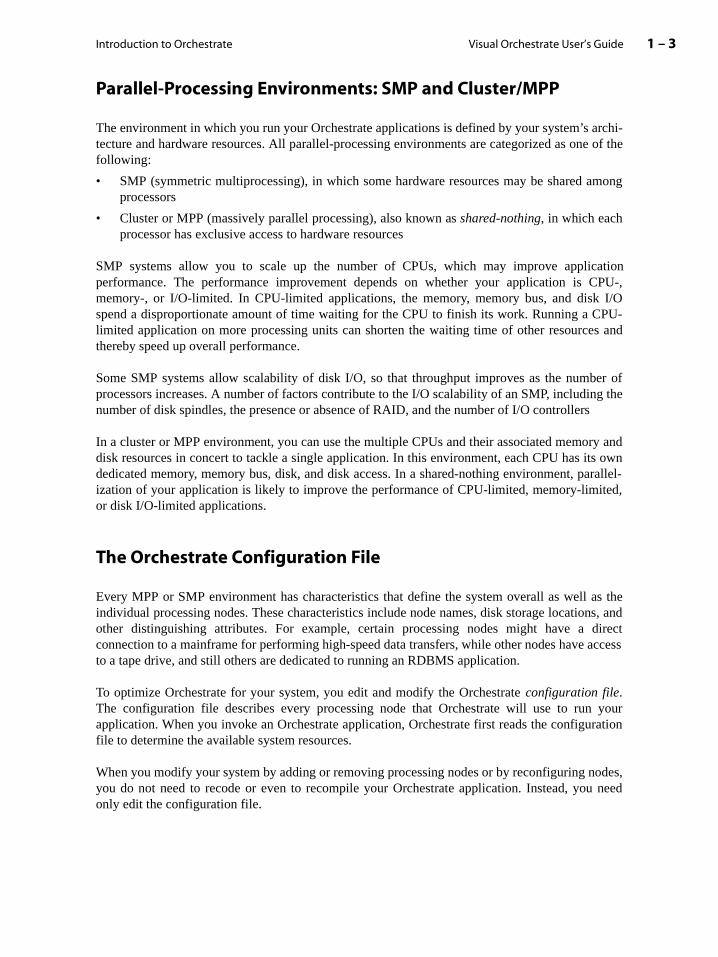
Parallel-Processing Environments: SMP and Cluster/MPP
The environment in which you run your Orchestrate applications is defined by your system’s tecture and hardware resources. All parallel-processing environments are categorized as onfollowing:
• SMP (symmetric multiprocessing), in which some hardware resources may be shared processors
• Cluster or MPP (massively parallel processing), also known as shared-nothing, in which eachprocessor has exclusive access to hardware resources
SMP systems allow you to scale up the number of CPUs, which may improve applicperformance. The performance improvement depends on whether your application is memory-, or I/O-limited. In CPU-limited applications, the memory, memory bus, and diskspend a disproportionate amount of time waiting for the CPU to finish its work. Running a Climited application on more processing units can shorten the waiting time of other resourcethereby speed up overall performance.
Some SMP systems allow scalability of disk I/O, so that throughput improves as the numprocessors increases. A number of factors contribute to the I/O scalability of an SMP, includinumber of disk spindles, the presence or absence of RAID, and the number of I/O controllers
In a cluster or MPP environment, you can use the multiple CPUs and their associated memodisk resources in concert to tackle a single application. In this environment, each CPU has idedicated memory, memory bus, disk, and disk access. In a shared-nothing environment, pization of your application is likely to improve the performance of CPU-limited, memory-limitor disk I/O-limited applications.
The Orchestrate Configuration File
Every MPP or SMP environment has characteristics that define the system overall as wellindividual processing nodes. These characteristics include node names, disk storage locatioother distinguishing attributes. For example, certain processing nodes might have a connection to a mainframe for performing high-speed data transfers, while other nodes haveto a tape drive, and still others are dedicated to running an RDBMS application.
To optimize Orchestrate for your system, you edit and modify the Orchestrate configuration file.The configuration file describes every processing node that Orchestrate will use to runapplication. When you invoke an Orchestrate application, Orchestrate first reads the configufile to determine the available system resources.
When you modify your system by adding or removing processing nodes or by reconfiguring nyou do not need to recode or even to recompile your Orchestrate application. Instead, yoonly edit the configuration file.

Visual Orchestrate User’s Guide1 – 4 Orchestrate Application Components
n. Forisual
tion,
Another benefit of the configuration file is the control it gives you over parallelization of yourapplication during the development cycle. For example, by editing the configuration file, you canfirst execute your application on a single processing node, then on two nodes, then four, then eight,and so forth. The configuration file lets you measure system performance and scalability withoutmodifying your application code.
For complete information on configuration files, see the Orchestrate Installation andAdministration Manual.
Orchestrate Application Components
You create Orchestrate applications with three basic components:
• Data sets: Sets of data processed by the Orchestrate application
• Operators: Basic functional units of an Orchestrate application
• Steps: Groups of Orchestrate operators that process the application’s data
The Visual Orchestrate graphical user interface lets you easily create and run an applicatioinstructions on using Visual Orchestrate, see the chapter “Creating Applications with VOrchestrate”.
The following figure shows a Visual Orchestrate Program window with a sample applicademonstrating all three Orchestrate components—data sets, operators, and steps:
Introduction to Orchestrate 1 – 5Visual Orchestrate User’s Guide
rds,e anThe
RMIX
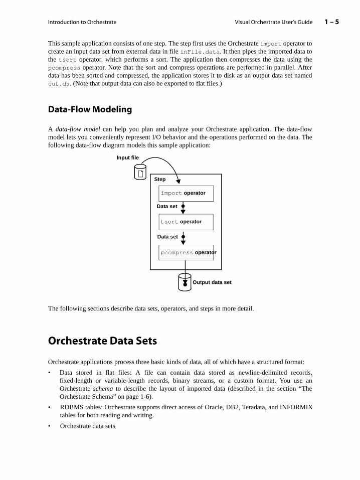
This sample application consists of one step. The step first uses the Orchestrate import operator tocreate an input data set from external data in file inFile.data. It then pipes the imported data tothe tsort operator, which performs a sort. The application then compresses the data using thepcompress operator. Note that the sort and compress operations are performed in parallel. Afterdata has been sorted and compressed, the application stores it to disk as an output data set namedout.ds. (Note that output data can also be exported to flat files.)
Data-Flow Modeling
A data-flow model can help you plan and analyze your Orchestrate application. The data-flowmodel lets you conveniently represent I/O behavior and the operations performed on the data. Thefollowing data-flow diagram models this sample application:
The following sections describe data sets, operators, and steps in more detail.
Orchestrate Data Sets
Orchestrate applications process three basic kinds of data, all of which have a structured format:
• Data stored in flat files: A file can contain data stored as newline-delimited recofixed-length or variable-length records, binary streams, or a custom format. You usOrchestrate schema to describe the layout of imported data (described in the section “Orchestrate Schema” on page 1-6).
• RDBMS tables: Orchestrate supports direct access of Oracle, DB2, Teradata, and INFOtables for both reading and writing.
• Orchestrate data sets
Data set
Data set
tsort operator
pcompress operator
Input file
import operator
Output data set
Step

Visual Orchestrate User’s Guide1 – 6 Orchestrate Data Sets
ssingracle,
e further
ecords.at the
lso of field
ample,ta type,(Filechema
ithout lan- record
A data set is the body of data that is input to or output from an Orchestrate application. Orchestrateprocesses record-based data in parallel, so the data set that is input to an Orchestrate applicationalways has a record format. Orchestrate’s record-based processing is similar to the proceperformed by an RDBMS (relational database management system), such as DB2, OTeradata, or INFORMIX.
Record-based data is structured as rows, each of which represents a record. Records ardivided into fields, where a field is defined by a field identifier, or name, and a field data type.
As an example, the following figure shows a record-based data set:
In the figure above, a data set is represented by a table with multiple rows, representing rEach record has five data fields, represented by columns. All fields are of fixed length, so threcords are all the same length.
A record format can also include one or more variable-length fields, so that the record is avariable length. A variable-length field indicates its length either by marking the end of thewith a delimiter character or by including information indicating the length.
The Orchestrate Schema
In Orchestrate, the record structure of a data set is defined by an Orchestrate record schema, whichis a form of metadata. Many data processing applications include metadata support. For exan RDBMS uses metadata to define the layout of a database table, including the name, daand other attributes of every record field. Also, COBOL programs can contain an FD Description) section to describe the layout of a COBOL data file. For details on Orchestrate scapabilities and usage, see the section “Defining a Record Schema” on page 4-16.
An Orchestrate record schema allows you to reference an individual field by its name, wknowing the field’s exact location within the record. You use the Orchestrate data definitionguage to define a schema for a data set only once. The following is a sample Orchestrateschema:
.
.
.
Columns represent fields
Rows represent records
Table of fixed-length records
A record
int32int32 int16 sfloat string[10]
Introduction to Orchestrate 1 – 7Visual Orchestrate User’s Guide
iable-ample
can use UNIXto an
ust be by the
e in the
record (a:int32;b:int32;c:int16;d:sfloat;e:string[10] )
An Orchestrate record definition consists of the keyword record, followed by a parenthesized listof semicolon-separated field definitions. You can optionally include a terminating semicolon afterthe last field definition.
Each field definition consists of the field’s name, a colon, and the field’s data type. For a varlength data type, such as a string, you can include an optional length specifier; in the exabove, string e is specified to have the length 10.
A central feature of the Orchestrate record schema facility is flexibility. With schemas, you cancreate a range of record layouts as well as support existing database table standards. Youschemas to represent existing data formats for RDBMS data tables, COBOL data files, anddata files. Schema flexibility is also very advantageous when you read external data inOrchestrate application (import), or write Orchestrate data to an external format (export).
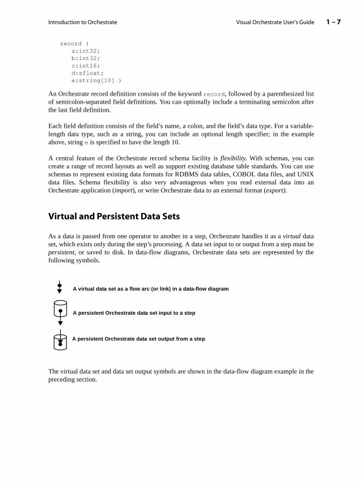
Virtual and Persistent Data Sets
As a data is passed from one operator to another in a step, Orchestrate handles it as a virtual dataset, which exists only during the step’s processing. A data set input to or output from a step mpersistent, or saved to disk. In data-flow diagrams, Orchestrate data sets are representedfollowing symbols.
The virtual data set and data set output symbols are shown in the data-flow diagram examplpreceding section.
A virtual data set as a flow arc (or link) in a data-flow diagram
A persistent Orchestrate data set input to a step
A persistent Orchestrate data set output from a step
Visual Orchestrate User’s Guide1 – 8 Orchestrate Data Sets
tomust be
file),
ort
MIX.l:
t. Whent of the
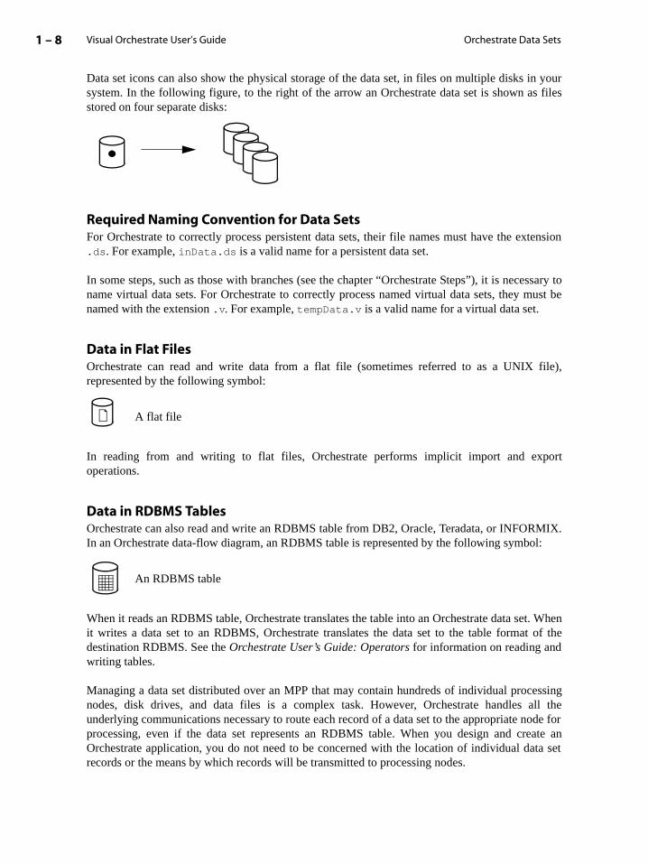
Data set icons can also show the physical storage of the data set, in files on multiple disks in yoursystem. In the following figure, to the right of the arrow an Orchestrate data set is shown as filesstored on four separate disks:
Required Naming Convention for Data SetsFor Orchestrate to correctly process persistent data sets, their file names must have the extension.ds. For example, inData.ds is a valid name for a persistent data set.
In some steps, such as those with branches (see the chapter “Orchestrate Steps”), it is necessaryname virtual data sets. For Orchestrate to correctly process named virtual data sets, they named with the extension .v. For example, tempData.v is a valid name for a virtual data set.
Data in Flat FilesOrchestrate can read and write data from a flat file (sometimes referred to as a UNIXrepresented by the following symbol:
In reading from and writing to flat files, Orchestrate performs implicit import and expoperations.
Data in RDBMS TablesOrchestrate can also read and write an RDBMS table from DB2, Oracle, Teradata, or INFORIn an Orchestrate data-flow diagram, an RDBMS table is represented by the following symbo
When it reads an RDBMS table, Orchestrate translates the table into an Orchestrate data seit writes a data set to an RDBMS, Orchestrate translates the data set to the table formadestination RDBMS. See the Orchestrate User’s Guide: Operators for information on reading andwriting tables.
Managing a data set distributed over an MPP that may contain hundreds of individual processingnodes, disk drives, and data files is a complex task. However, Orchestrate handles all theunderlying communications necessary to route each record of a data set to the appropriate node forprocessing, even if the data set represents an RDBMS table. When you design and create anOrchestrate application, you do not need to be concerned with the location of individual data setrecords or the means by which records will be transmitted to processing nodes.
A flat file
An RDBMS table

Introduction to Orchestrate 1 – 9Visual Orchestrate User’s Guide
m” onu may other
f your
of anut, andnts an
next, inmportsequentsectionh an
arallel youra singlets you
For more information about data sets, see the chapter “Orchestrate Data Sets”.
Partitioning Data Sets
The benefits of partitioning your data sets were introduced in the section “Partition Parallelispage 1-2. Orchestrate allows you to control how your data is partitioned. For example, yowant to partition your data in a particular way to perform an operation such as a sort. On thehand, you may have an application that partitions data solely to optimize the speed oapplication. See the chapter “Partitioning in Orchestrate” for more information.
Orchestrate Operators
Orchestrate operators, which process or analyze data, are the basic functional unitsOrchestrate application. An operator can take data sets, RDBMS tables, or data files as inpcan produce data sets, RDBMS tables, or data files as output. The following figure represeOrchestrate operator in a data-flow diagram:
The operators in your Orchestrate application pass data records from one operator to the pipeline fashion. For example, the operators in an application step might start with an ioperator, which reads data from a file and converts it to an Orchestrate data set. Suboperators in the sequence could perform various processing and analysis tasks. In the “Data-Flow Modeling” on page 1-5, you saw a more detailed data-flow diagram of sucOrchestrate application.
The processing power of Orchestrate derives largely from its ability to execute operators in pon multiple processing nodes. You will likely use parallel operators for most processing inOrchestra applications. Orchestrate also supports sequential operators, which execute on processing node. Orchestrate provide libraries of general-purpose operators, and it also lecreate custom operators (see the section “Prebuilt and Custom Operators” on page 1-10).
. . .
. . .
Input data sets
Output data sets
Operator
Visual Orchestrate User’s Guide1 – 10 Orchestrate Operators
ate willn.
ide ofxecutesates theg nodes
urailable tos with
luding
Operator Execution
By default, Orchestrate operators execute on all processing nodes in your system. Orchestratedynamically scales your application up or down in response to system configuration changes,without requiring you to modify your application. This capability means that if you develop parallelapplications for a small system and later increase your system’s processing power, Orchestrautomatically scale up those applications to take advantage of your new system configuratio
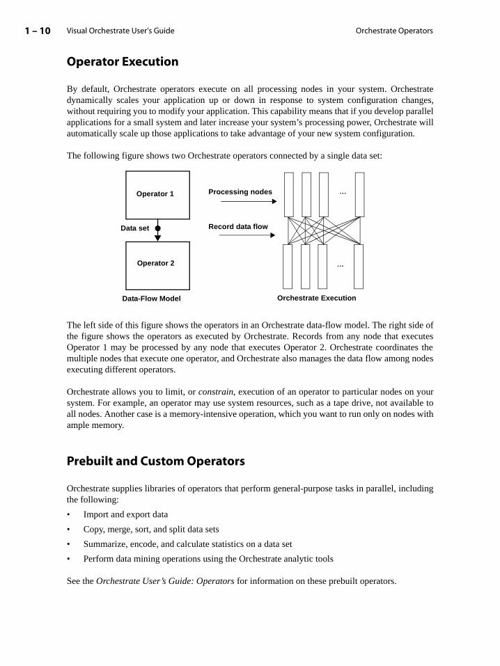
The following figure shows two Orchestrate operators connected by a single data set:
The left side of this figure shows the operators in an Orchestrate data-flow model. The right sthe figure shows the operators as executed by Orchestrate. Records from any node that eOperator 1 may be processed by any node that executes Operator 2. Orchestrate coordinmultiple nodes that execute one operator, and Orchestrate also manages the data flow amonexecuting different operators.
Orchestrate allows you to limit, or constrain, execution of an operator to particular nodes on yosystem. For example, an operator may use system resources, such as a tape drive, not avall nodes. Another case is a memory-intensive operation, which you want to run only on nodeample memory.
Prebuilt and Custom Operators
Orchestrate supplies libraries of operators that perform general-purpose tasks in parallel, incthe following:
• Import and export data
• Copy, merge, sort, and split data sets
• Summarize, encode, and calculate statistics on a data set
• Perform data mining operations using the Orchestrate analytic tools
See the Orchestrate User’s Guide: Operators for information on these prebuilt operators.
...
...
Operator 1
Data set
Operator 2
Data-Flow Model
Record data flow
Processing nodes
Orchestrate Execution
Introduction to Orchestrate 1 – 11Visual Orchestrate User’s Guide
rator
ative)your
c-
arallel
BMSent datatep exe- cannot
to othernt data
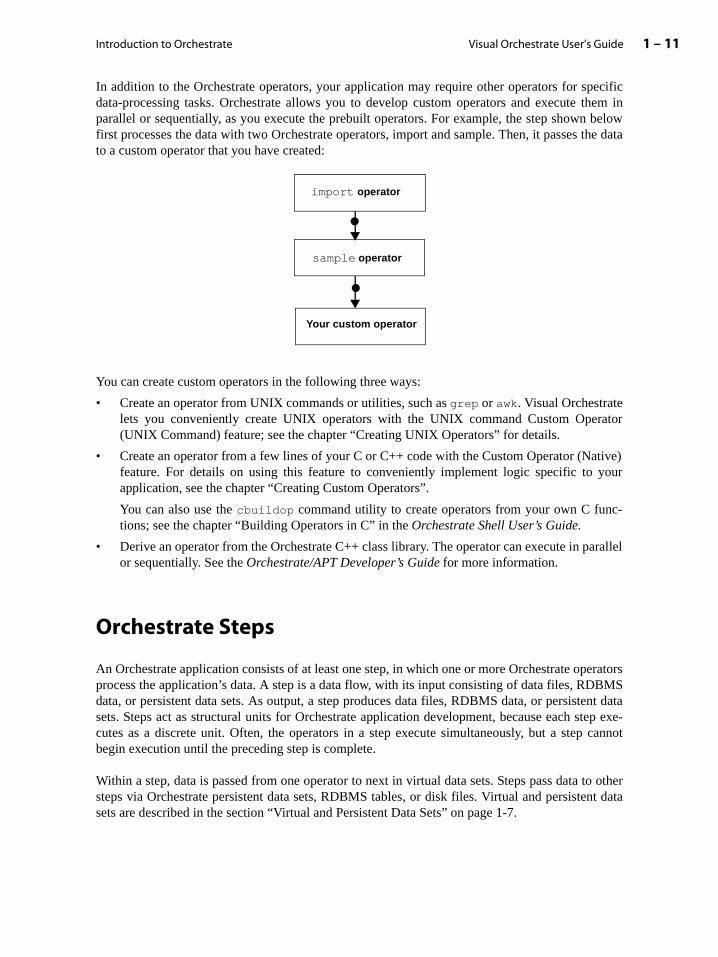
In addition to the Orchestrate operators, your application may require other operators for specificdata-processing tasks. Orchestrate allows you to develop custom operators and execute them inparallel or sequentially, as you execute the prebuilt operators. For example, the step shown belowfirst processes the data with two Orchestrate operators, import and sample. Then, it passes the datato a custom operator that you have created:
You can create custom operators in the following three ways:
• Create an operator from UNIX commands or utilities, such as grep or awk. Visual Orchestratelets you conveniently create UNIX operators with the UNIX command Custom Ope(UNIX Command) feature; see the chapter “Creating UNIX Operators” for details.
• Create an operator from a few lines of your C or C++ code with the Custom Operator (Nfeature. For details on using this feature to conveniently implement logic specific to application, see the chapter “Creating Custom Operators”.
You can also use the cbuildop command utility to create operators from your own C funtions; see the chapter “Building Operators in C” in the Orchestrate Shell User’s Guide.
• Derive an operator from the Orchestrate C++ class library. The operator can execute in por sequentially. See the Orchestrate/APT Developer’s Guide for more information.
Orchestrate Steps
An Orchestrate application consists of at least one step, in which one or more Orchestrate operatorsprocess the application’s data. A step is a data flow, with its input consisting of data files, RDdata, or persistent data sets. As output, a step produces data files, RDBMS data, or persistsets. Steps act as structural units for Orchestrate application development, because each scutes as a discrete unit. Often, the operators in a step execute simultaneously, but a stepbegin execution until the preceding step is complete.
Within a step, data is passed from one operator to next in virtual data sets. Steps pass datasteps via Orchestrate persistent data sets, RDBMS tables, or disk files. Virtual and persistesets are described in the section “Virtual and Persistent Data Sets” on page 1-7.
import operator
sample operator
Your custom operator

Visual Orchestrate User’s Guide1 – 12 Orchestrate Steps
In the figure below, the final operator in Step 1 writes its resulting data to two persistent data sets.Operators in Step 2 read these data sets as input.
A step is also the unit of error handling in an Orchestrate application. All operators within a stepsucceed or fail as a unit, allowing you to conditionalize application execution based on the resultsof a step. In the event of a failure during step execution, the Orchestrate framework performs allnecessary clean up of your system. This includes deleting any files used for temporary storage andthe freeing of any system resources used by the step.
For more information about steps, see the chapter “Orchestrate Steps”.
Step 1
Step 2
Operator
Operator
Operator
Operator
Virtualdata set
Introduction to Orchestrate 1 – 13Visual Orchestrate User’s Guide
trate’snitoragram
licationon stepn of
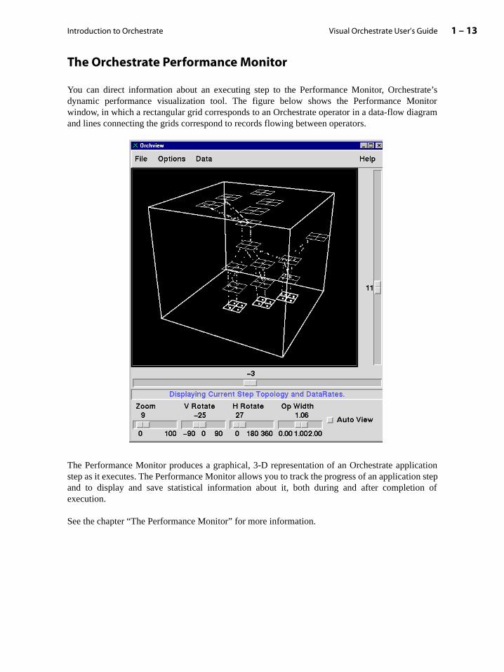
The Orchestrate Performance Monitor
You can direct information about an executing step to the Performance Monitor, Orchesdynamic performance visualization tool. The figure below shows the Performance Mowindow, in which a rectangular grid corresponds to an Orchestrate operator in a data-flow diand lines connecting the grids correspond to records flowing between operators.
The Performance Monitor produces a graphical, 3-D representation of an Orchestrate appstep as it executes. The Performance Monitor allows you to track the progress of an applicatiand to display and save statistical information about it, both during and after completioexecution.
See the chapter “The Performance Monitor” for more information.

Visual Orchestrate User’s Guide1 – 14 Creating Orchestrate Applications
uced in chap-
tions
, to sim-et of
iles,n fileine allodes byura-
es youre the
art by pro- con-stom the-10.
nables then
file.
Creating Orchestrate Applications
The following is a general procedure for developing an Orchestrate application:
1. Create a data-flow model of your application. Data-flow models are introduced in the section“Data-Flow Modeling” on page 1-5.
2. Create any custom operators required by your application. Custom operators are introdthe section “Prebuilt and Custom Operators” on page 1-10 and described in detail in theter “Orchestrate Operators”.
3. Develop your application using Visual Orchestrate (see the chapter “Creating Applicawith Visual Orchestrate”).
4. Create a test data set. As many Orchestrate applications process huge amounts of dataplify and speed debugging you will probably want to test your application first on a subsyour data.
5. Create or edit your configuration file(s). You might want to create different configuration ffor use at different stages of application development. For example, one configuratiocould define a single node, a second could define a few nodes, and a third could defnodes in your system. Then, as testing progressed, you could increase the number of nchanging the environment variable APT_CONFIG_FILE to point to the appropriate configtion file. The Orchestrate Installation and Administration Manual describes configuration filesand environment variables in detail.
6. Run and debug your application in sequential execution mode. Sequential mode executapplication on a single processing node; the configuration file is used only to determinnumber of partitions into which data sets are divided for parallel operators. You can stusing only a single partition, while you concentrate on testing and debugging your maingram and operators. Later, you can use a different configuration file (or edit your originalfiguration file) to increase the number of partitions and, if applicable, to test your cupartitioning. Partitioning is described in the chapter “Partitioning in Orchestrate”, anddebugging process is described in the section “Setting Step Execution Modes” on page 6
7. Run and debug your application in parallel execution mode. Parallel execution mode ethe full functionality of Orchestrate. You can start by running in parallel on a single node,on a few nodes, and complete testing by running on the full parallel system.
Orchestrate Installation and Administration
The Orchestrate Installation and Administration Manual thoroughly describes installation andadministration tasks, such as setting environment variables and maintaining a configuration
2 – 1Visual Orchestrate User’s Guide
ug the
2: Creating Applications with Visual Orchestrate
The Orchestrate graphical user interface, Visual Orchestrate, lets you create Orchestrateapplications from data-flow components (operators, data sets, and steps) in a Microsoft Win-dows development environment. After you have created the data-flow diagram, you candeploy the application on your UNIX system.
This chapter describes how to use Visual Orchestrate to create and deploy an Orchestrateapplication, in the following sections:
• “The Orchestrate Development Environment” on page 2-1
• “Creating an Orchestrate Application” on page 2-3
• “Deploying the Application on Your UNIX System” on page 2-6
• “Setting User Preferences” on page 2-9
• “Setting Program Directory Paths” on page 2-13
• “Visual Orchestrate Utilities” on page 2-14
The Orchestrate Development Environment
At the most general level, developing an application for Orchestrate has two phases:
1. Developing and testing the application on PC running Microsoft Windows.
2. Deploying the application on a target UNIX machine.
Orchestrate uses a client-server development environment, in which you develop applications on aPC running Microsoft Windows (95, 98, or NT). The PC is then connected over a network to thetarget UNIX machine. This development environment allows you to use Visual Orchestrate,Orchestrate’s graphical user interface, to develop your application, and then run and debapplication on the target machine.

Visual Orchestrate User’s Guide2 – 2 The Orchestrate Development Environment
The following figure shows the Orchestrate development environment:
The Orchestrate server performs three basic tasks:
1. Stores your application.
2. Stores configuration information about the UNIX target system.
3. Controls and coordinates the execution of Orchestrate applications.
For Orchestration application development to take place, the Orchestrate server must be running onthe target machine. You must designate an Orchestrate server administrator. The Orchestrateserver administrator could be your system administrator or another person responsible formanaging your target UNIX system. The Orchestrate server administrator is responsible forconfiguring and managing the Orchestrate server. For detailed information on Orchestrate serveradministration, see the Orchestrate Installation and Administration Manual.
The Orchestrate client, Visual Orchestrate, is a graphical development tool that you use on a PC tocreate Orchestrate applications. Shown below is the main window of Visual Orchestrate:
Orchestrate client
Network
Orchestrate server(UNIX)
(Microsoft Windows)
. . .
Orchestrate client(Microsoft Windows)
Creating Applications with Visual Orchestrate 2 – 3Visual Orchestrate User’s Guide
You develop your Orchestrate application by creating and configuring Orchestrate data sets,operators, and steps. Using Visual Orchestrate, you can also execute and debug your application onthe target UNIX system.
When your application is complete and ready for deployment, you run the deployed applicationthrough either Visual Orchestrate or the Orchestrate UNIX-based deployment tools. These toolsallow you to incorporate your Orchestrate application into a larger application that may run as partof an overnight batch job or run under a UNIX job control application.
Creating an Orchestrate Application
This section describes the basic procedure that you follow to create an Orchestrate applicationusing Visual Orchestrate.
1. Start Visual Orchestrate by clicking on the Windows Start button, then choosing Programs ->Visual Orchestrate -> Visual Orchestrate.
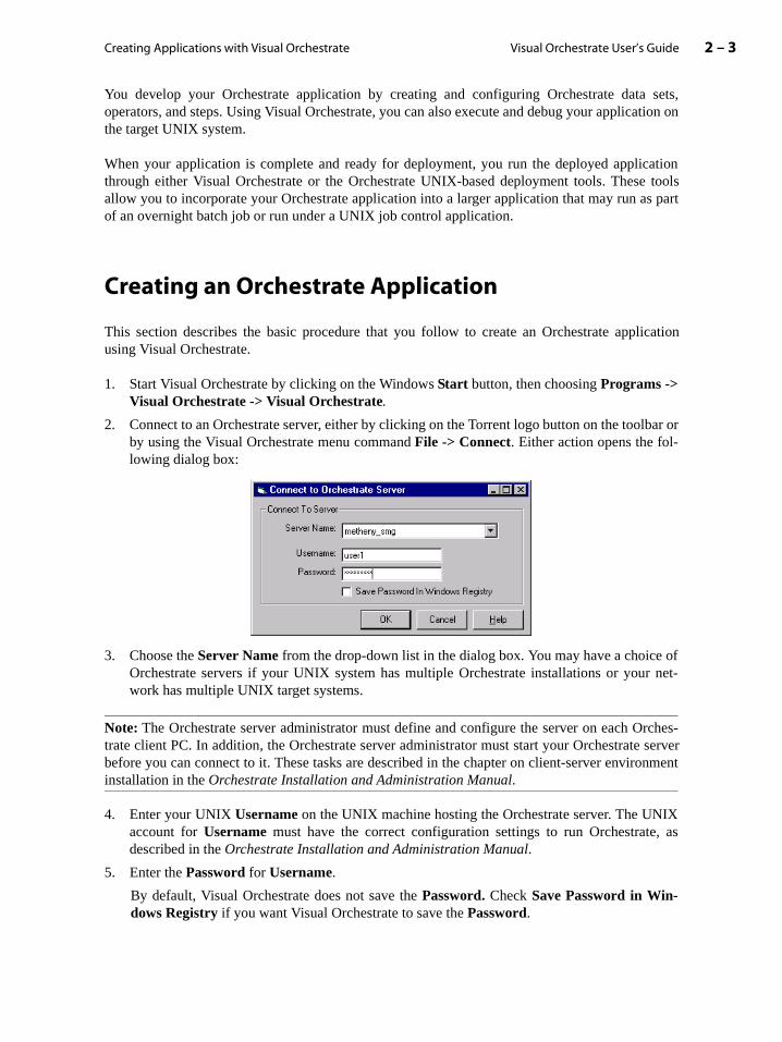
2. Connect to an Orchestrate server, either by clicking on the Torrent logo button on the toolbar orby using the Visual Orchestrate menu command File -> Connect. Either action opens the fol-lowing dialog box:
3. Choose the Server Name from the drop-down list in the dialog box. You may have a choice ofOrchestrate servers if your UNIX system has multiple Orchestrate installations or your net-work has multiple UNIX target systems.
Note: The Orchestrate server administrator must define and configure the server on each Orches-trate client PC. In addition, the Orchestrate server administrator must start your Orchestrate serverbefore you can connect to it. These tasks are described in the chapter on client-server environmentinstallation in the Orchestrate Installation and Administration Manual.
4. Enter your UNIX Username on the UNIX machine hosting the Orchestrate server. The UNIXaccount for Username must have the correct configuration settings to run Orchestrate, asdescribed in the Orchestrate Installation and Administration Manual.
5. Enter the Password for Username.
By default, Visual Orchestrate does not save the Password. Check Save Password in Win-dows Registry if you want Visual Orchestrate to save the Password.
Visual Orchestrate User’s Guide2 – 4 Creating an Orchestrate Application
6. If you are creating a new program, choose File -> New from the Visual Orchestrate menu. Thisopens an empty Program Editor window. You develop a complete application (containingdata sets, operators, and steps) in a single Program Editor window.
If you are editing an existing program, choose File -> Open and select the program from thelist of stored programs.
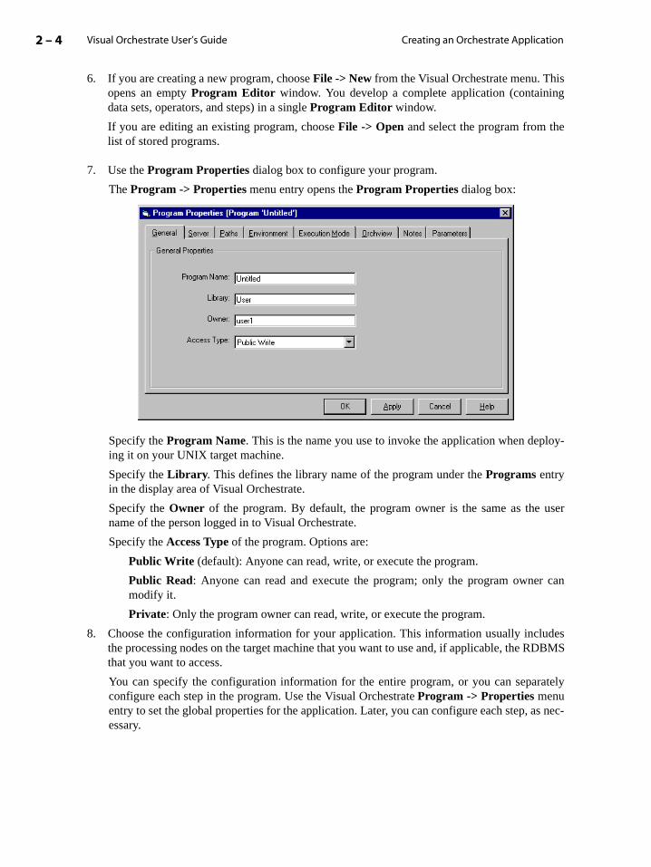
7. Use the Program Properties dialog box to configure your program.
The Program -> Properties menu entry opens the Program Properties dialog box:
Specify the Program Name. This is the name you use to invoke the application when deploy-ing it on your UNIX target machine.
Specify the Library. This defines the library name of the program under the Programs entryin the display area of Visual Orchestrate.
Specify the Owner of the program. By default, the program owner is the same as the username of the person logged in to Visual Orchestrate.
Specify the Access Type of the program. Options are:
Public Write (default): Anyone can read, write, or execute the program.
Public Read: Anyone can read and execute the program; only the program owner canmodify it.
Private: Only the program owner can read, write, or execute the program.
8. Choose the configuration information for your application. This information usually includesthe processing nodes on the target machine that you want to use and, if applicable, the RDBMSthat you want to access.
You can specify the configuration information for the entire program, or you can separatelyconfigure each step in the program. Use the Visual Orchestrate Program -> Properties menuentry to set the global properties for the application. Later, you can configure each step, as nec-essary.

Creating Applications with Visual Orchestrate 2 – 5Visual Orchestrate User’s Guide
abasetabase
t least aonfig-
e and
ps” for
onreies
In the Program Properties dialog box, choose the Server tab to open the following form:
Configuration: Select the Orchestrate configuration used to execute the application. The configu-ration defines the processing nodes and disk drives available for use by your program. Often, theserver configuration is the only program property that you need to set.
The Orchestrate server administrator is required to set up at least a default configurationbefore you can create an Orchestrate program. If no configuration is available, see theOrchestrate server administrator.
You may have several different configurations available. For example, one configurationmay be for testing and another for production.
You can validate a configuration using the Tools->Check Config menu entry. See the sec-tion “Checking an Orchestrate Configuration” on page 2-14 for more information.
Database: (Optional) Specify the database configuration used by the application. The datconfiguration defines the database type (DB2, Informix, or Oracle), as well as the specific daconfiguration to use.
If you are accessing a database, the Orchestrate server administrator must set up adefault database configuration before you can create an Orchestrate program. If no curation is available, see the Orchestrate server administrator.
You may have several different configurations available, depending on the databasdatabase data that you want to access.
Execution Options: Select Check Only to validate the step but not to run it, and Execute to exe-cute the step.
Leave the remaining settings in their default state. See the chapter “Orchestrate Stemore information.
Note: For information on the Paths settings, see the section “Setting Program Directory Paths”page 2-13. For information on the Environment and Execution Mode tabs, see the chapte“Orchestrate Steps”. For information on the Orchview tab, See the chapter “The PerformancMonitor”. For information on the Parameters tab, see the section “Using the Program PropertDialog Box to Set Program Parameters” on page 2-15.
Visual Orchestrate User’s Guide2 – 6 Deploying the Application on Your UNIX System
that
datage.
il you
strate
-
ribes
canutes
. Ther the
developto use
9. Develop your application by creating a data-flow diagram containing data sets, operators, andsteps, as described in the chapter “Orchestrate Steps”.
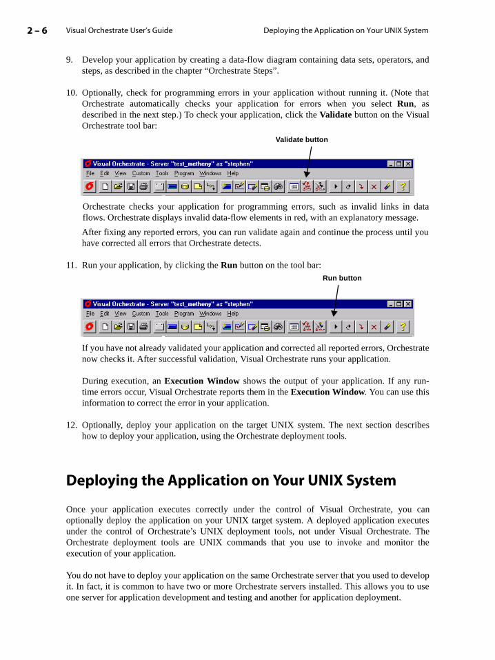
10. Optionally, check for programming errors in your application without running it. (Note Orchestrate automatically checks your application for errors when you select Run, asdescribed in the next step.) To check your application, click the Validate button on the VisualOrchestrate tool bar:
Orchestrate checks your application for programming errors, such as invalid links inflows. Orchestrate displays invalid data-flow elements in red, with an explanatory messa
After fixing any reported errors, you can run validate again and continue the process unthave corrected all errors that Orchestrate detects.
11. Run your application, by clicking the Run button on the tool bar:
If you have not already validated your application and corrected all reported errors, Orchenow checks it. After successful validation, Visual Orchestrate runs your application.
During execution, an Execution Window shows the output of your application. If any runtime errors occur, Visual Orchestrate reports them in the Execution Window. You can use thisinformation to correct the error in your application.
12. Optionally, deploy your application on the target UNIX system. The next section deschow to deploy your application, using the Orchestrate deployment tools.
Deploying the Application on Your UNIX System
Once your application executes correctly under the control of Visual Orchestrate, youoptionally deploy the application on your UNIX target system. A deployed application execunder the control of Orchestrate’s UNIX deployment tools, not under Visual OrchestrateOrchestrate deployment tools are UNIX commands that you use to invoke and monitoexecution of your application.
You do not have to deploy your application on the same Orchestrate server that you used to it. In fact, it is common to have two or more Orchestrate servers installed. This allows you one server for application development and testing and another for application deployment.
Validate button
Run button

Creating Applications with Visual Orchestrate 2 – 7Visual Orchestrate User’s Guide
g
oke.
essary,
Before deploying your application, you can use the File menu command (File -> Copy To) to copya program, Orchestrate configuration, custom operator, or schema from the server to which you arecurrently connected, to another server.
Deploying Your Application with job-manager
To deploy and manage your application on your target UNIX system, you use the Orchestrate util-ity job-manager. The job-manager utility is located in install_dir/apt/bin, whereinstall_dir is the path to the Orchestrate installation. You must either include this directory inyour UNIX PATH or provide the complete path name to the utility.
You run job-manager with the following command:
$ job-manager command
where command is the command option to job-manager. The command options are:
• run jobname
• abandon jobinstance
• restart jobinstance
• kill jobinstance
• errors jobinstance
Note: Before you run your application with job-manager, you must execute it at least once usinVisual Orchestrate.
Running your ApplicationTo invoke an Orchestrate application developed using Visual Orchestrate, you use the run com-mand with job-manager. This command takes the name of the Orchestrate application to invAn Orchestrate application name has the form:
libname:progname
To find the libname and progname, see the Program Properties dialog box, General tab, fieldsLibrary and Program Name.
The application executes using the current server configuration. You can examine and, if necmodify this server configuration using the set-server-parameters command. See theOrchestrate Installation and Administration Manual for information on using this command.
The following is an example of the run command:
$ job-manager run User:myApp > jobInstance.txt

Visual Orchestrate User’s Guide2 – 8 Deploying the Application on Your UNIX System
Checking the Job Instance Number and Exit StatusIn the example above, job-manager executes the application named User:myApp. If theapplication completes successfully, job-manager writes the job instance number to the filejobinstance.txt. The Orchestrate server assigns an instance number to each run of yourapplication. Therefore, if you invoke multiple instances of User:myApp, you can identify eachinstance by its job instance number. All job-manager commands (other than run), take as anargument a job instance number.
As your application executes, the Orchestrate server also writes error messages to jobin-stance.txt. It is recommended that immediately after your application run completes, you do thefollowing:
1. Check the exit status of the job-manager command that you used to run the application, as youcheck the exit status of any other UNIX shell command.
2. Execute the following command to display any run-time error messages:
$ job-manager errors ’cat jobInstance.txt’
Terminating an Application RunTo terminate an Orchestrate application, you must first terminate the job-manager command. Ifyou used the keyboard to invoke the job-manager command, terminate it by pressing <Ctrl-C>.
If the job-manager command was invoked from a script, you must first halt the script. Then, termi-nate the Orchestrate application by using the following command:
$ job-manager kill ’cat jobInstance.txt’
Summary of Deployment Commands
The following table lists the commands, and command options, to job-manager:
Command Use
run run jobname
Executes the application identified by jobname, which has the form:
libname:progname
The Library and Program Name entries in the General tab are of the Pro-gram Properties dialog box define this information.
abandon abandon jobinstance
If your application terminates during a restartable step, this command deletes all data added to any output persistent data sets by all iterations of the abandoned step. Specifying this option means you cannot resume the application.
jobinstance specifies the Orchestrate job number as returned by the run command.

Creating Applications with Visual Orchestrate 2 – 9Visual Orchestrate User’s Guide
ra-is box
Refer to the Orchestrate Installation and Administration Manual for a further discussion ofdeployment.
Setting User Preferences
You set preferences for Visual Orchestrate through the Tools menu. Select Tools->Options to openthe following dialog box:
From the General tab:
• Click Show Link Numbers to configure Visual Orchestrate to show the number of the opetor output and operator input for each end of a link between two operators. By default, th
kill kill jobinstance
Terminates an executing application.
jobinstance specifies the Orchestrate job number as returned by the run command.
errors errors jobinstance
Displays on the screen any error messages generated by an application.
jobinstance specifies the Orchestrate job number as returned by the run command.
Command Use
Visual Orchestrate User’s Guide2 – 10 Setting User Preferences
tep
he
. Byext time
-
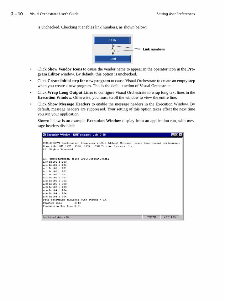
is unchecked. Checking it enables link numbers, as shown below:
• Click Show Vendor Icons to cause the vendor name to appear in the operator icon in the Pro-gram Editor window. By default, this option is unchecked.
• Click Create initial step for new program to cause Visual Orchestrate to create an empty swhen you create a new program. This is the default action of Visual Orchestrate.
• Click Wrap Long Output Lines to configure Visual Orchestrate to wrap long text lines in tExecution Window. Otherwise, you must scroll the window to view the entire line.
• Click Show Message Headers to enable the message headers in the Execution Windowdefault, message headers are suppressed. Your setting of this option takes effect the nyou run your application.
Shown below is an example Execution Window display from an application run, with message headers disabled:
Link numbers
Creating Applications with Visual Orchestrate 2 – 11Visual Orchestrate User’s Guide
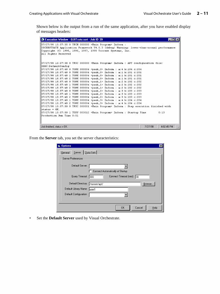
Shown below is the output from a run of the same application, after you have enabled displayof messages headers:
From the Server tab, you set the server characteristics:
• Set the Default Server used by Visual Orchestrate.
Visual Orchestrate User’s Guide2 – 12 Setting User Preferences
he
set-ll” on
mas
using
n
oning
for-
Set Connect Timeout to number of seconds that Visual Orchestrate will wait before sig-nalling a server-not-present error.
• Click Connect Automatically at Startup to cause Visual Orchestrate to connect to tDefault Server whenever you start Visual Orchestrate.
• Use Default Directory to set the server working directory for your applications, as well as ting the default path for the file browser and shell tool (see “Using the Orchestrate Shepage 2-15).
• Use Default Library to set the default library name for all programs, operators, and schethat you create.
• Set the default Orchestrate configuration for all programs created in Visual Orchestratethe Default Configuration pull-down list.
You can override the default configuration for a program (using the Program -> Propertiesmenu command) or for a step (by double clicking on the step to open the Step Properties dia-log box).
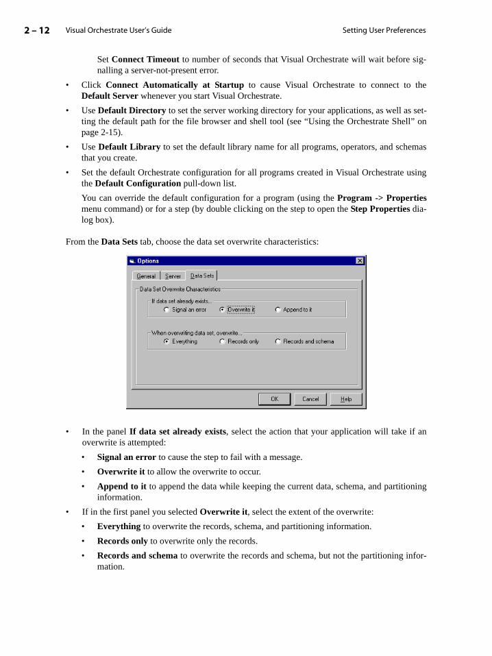
From the Data Sets tab, choose the data set overwrite characteristics:
• In the panel If data set already exists, select the action that your application will take if aoverwrite is attempted:
• Signal an error to cause the step to fail with a message.
• Overwrite it to allow the overwrite to occur.
• Append to it to append the data while keeping the current data, schema, and partitiinformation.
• If in the first panel you selected Overwrite it, select the extent of the overwrite:
• Everything to overwrite the records, schema, and partitioning information.
• Records only to overwrite only the records.
• Records and schema to overwrite the records and schema, but not the partitioning inmation.
Creating Applications with Visual Orchestrate 2 – 13Visual Orchestrate User’s Guide
ts”. For
the
t
ync-
nativer more
trate
For information on data sets and record schemas, see the chapter “Orchestrate Data Seinformation on partitioning, see the chapter “Partitioning in Orchestrate”.
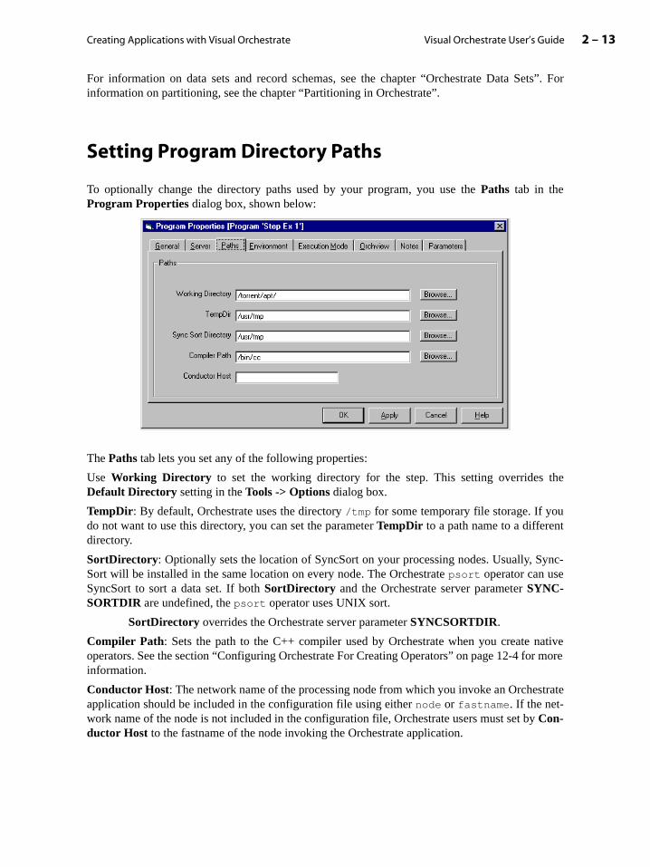
Setting Program Directory Paths
To optionally change the directory paths used by your program, you use the Paths tab in theProgram Properties dialog box, shown below:
The Paths tab lets you set any of the following properties:
Use Working Directory to set the working directory for the step. This setting overrides Default Directory setting in the Tools -> Options dialog box.
TempDir: By default, Orchestrate uses the directory /tmp for some temporary file storage. If youdo not want to use this directory, you can set the parameter TempDir to a path name to a differendirectory.
SortDirectory: Optionally sets the location of SyncSort on your processing nodes. Usually, SSort will be installed in the same location on every node. The Orchestrate psort operator can useSyncSort to sort a data set. If both SortDirectory and the Orchestrate server parameter SYNC-SORTDIR are undefined, the psort operator uses UNIX sort.
SortDirectory overrides the Orchestrate server parameter SYNCSORTDIR.
Compiler Path: Sets the path to the C++ compiler used by Orchestrate when you create operators. See the section “Configuring Orchestrate For Creating Operators” on page 12-4 foinformation.
Conductor Host: The network name of the processing node from which you invoke an Orchesapplication should be included in the configuration file using either node or fastname. If the net-work name of the node is not included in the configuration file, Orchestrate users must set byCon-ductor Host to the fastname of the node invoking the Orchestrate application.
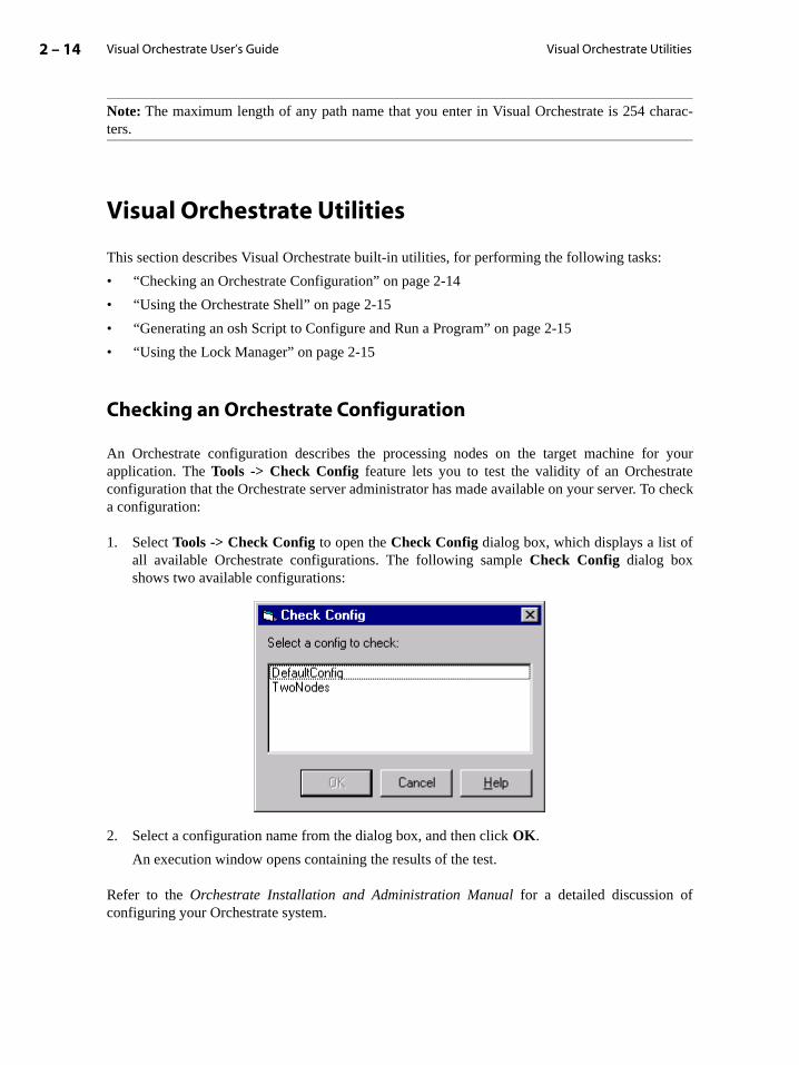
Visual Orchestrate User’s Guide2 – 14 Visual Orchestrate Utilities
r yourte
o check
Note: The maximum length of any path name that you enter in Visual Orchestrate is 254 charac-ters.
Visual Orchestrate Utilities
This section describes Visual Orchestrate built-in utilities, for performing the following tasks:
• “Checking an Orchestrate Configuration” on page 2-14
• “Using the Orchestrate Shell” on page 2-15
• “Generating an osh Script to Configure and Run a Program” on page 2-15
• “Using the Lock Manager” on page 2-15
Checking an Orchestrate Configuration
An Orchestrate configuration describes the processing nodes on the target machine foapplication. The Tools -> Check Config feature lets you to test the validity of an Orchestraconfiguration that the Orchestrate server administrator has made available on your server. Ta configuration:
1. Select Tools -> Check Config to open the Check Config dialog box, which displays a list ofall available Orchestrate configurations. The following sample Check Config dialog boxshows two available configurations:
2. Select a configuration name from the dialog box, and then click OK.
An execution window opens containing the results of the test.
Refer to the Orchestrate Installation and Administration Manual for a detailed discussion ofconfiguring your Orchestrate system.
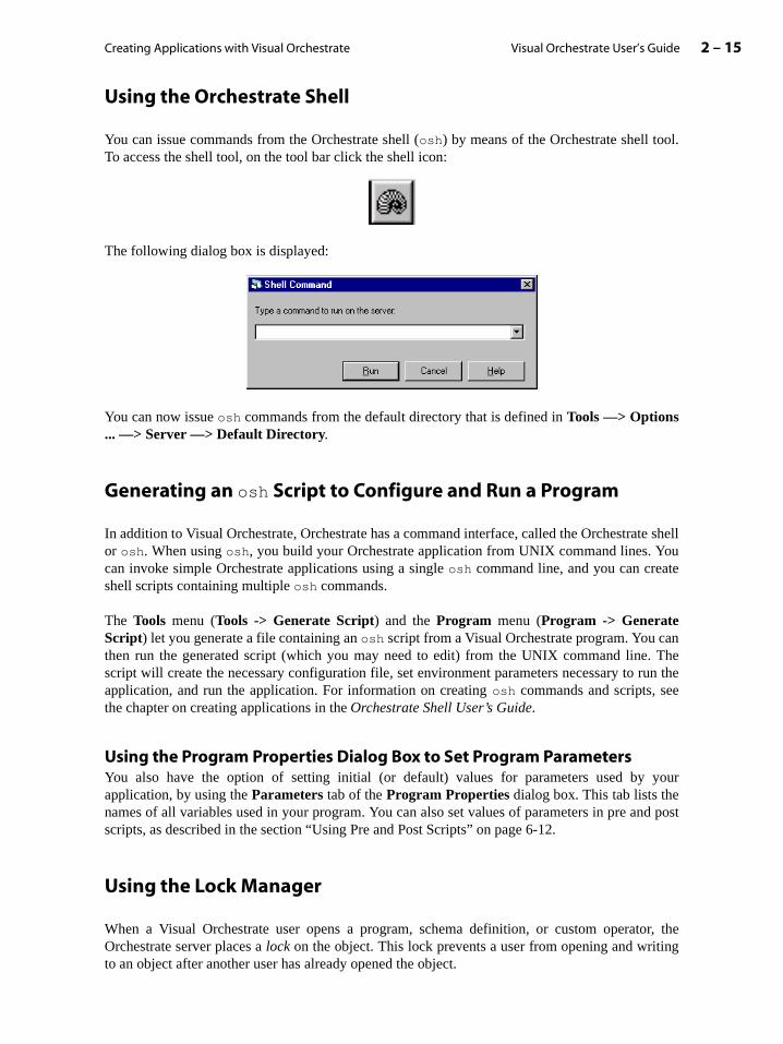
Creating Applications with Visual Orchestrate 2 – 15Visual Orchestrate User’s Guide
tor, theing
Using the Orchestrate Shell
You can issue commands from the Orchestrate shell (osh) by means of the Orchestrate shell tool.To access the shell tool, on the tool bar click the shell icon:
The following dialog box is displayed:
You can now issue osh commands from the default directory that is defined in Tools —> Options... —> Server —> Default Directory.
Generating an osh Script to Configure and Run a Program
In addition to Visual Orchestrate, Orchestrate has a command interface, called the Orchestrate shellor osh. When using osh, you build your Orchestrate application from UNIX command lines. Youcan invoke simple Orchestrate applications using a single osh command line, and you can createshell scripts containing multiple osh commands.
The Tools menu (Tools -> Generate Script) and the Program menu (Program -> GenerateScript) let you generate a file containing an osh script from a Visual Orchestrate program. You canthen run the generated script (which you may need to edit) from the UNIX command line. Thescript will create the necessary configuration file, set environment parameters necessary to run theapplication, and run the application. For information on creating osh commands and scripts, seethe chapter on creating applications in the Orchestrate Shell User’s Guide.
Using the Program Properties Dialog Box to Set Program ParametersYou also have the option of setting initial (or default) values for parameters used by yourapplication, by using the Parameters tab of the Program Properties dialog box. This tab lists thenames of all variables used in your program. You can also set values of parameters in pre and postscripts, as described in the section “Using Pre and Post Scripts” on page 6-12.
Using the Lock Manager
When a Visual Orchestrate user opens a program, schema definition, or custom operaOrchestrate server places a lock on the object. This lock prevents a user from opening and writto an object after another user has already opened the object.
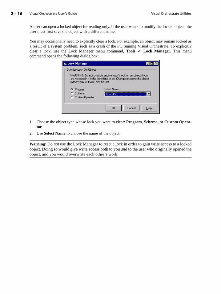
Visual Orchestrate User’s Guide2 – 16 Visual Orchestrate Utilities
A user can open a locked object for reading only. If the user wants to modify the locked object, theuser must first save the object with a different name.
You may occasionally need to explicitly clear a lock. For example, an object may remain locked asa result of a system problem, such as a crash of the PC running Visual Orchestrate. To explicitlyclear a lock, use the Lock Manager menu command, Tools -> Lock Manager. This menucommand opens the following dialog box:
1. Choose the object type whose lock you want to clear: Program, Schema, or Custom Opera-tor.
2. Use Select Name to choose the name of the object.
Warning: Do not use the Lock Manager to reset a lock in order to gain write access to a lockedobject. Doing so would give write access both to you and to the user who originally opened theobject, and you would overwrite each other’s work.
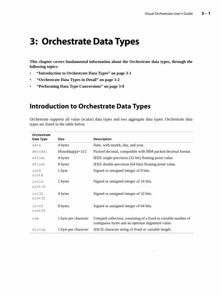
3 – 1Visual Orchestrate User’s Guide
3: Orchestrate Data Types
This chapter covers fundamental information about the Orchestrate data types, through thefollowing topics:
• “Introduction to Orchestrate Data Types” on page 3-1
• “Orchestrate Data Types in Detail” on page 3-2
• “Performing Data Type Conversions” on page 3-8
Introduction to Orchestrate Data Types
Orchestrate supports all value (scalar) data types and two aggregate data types. Orchestrate datatypes are listed in the table below.
Orchestrate Data Type Size Description
date 4 bytes Date, with month, day, and year.
decimal (Roundup(p)+1)/2 Packed decimal, compatible with IBM packed decimal format.
sfloat 4 bytes IEEE single-precision (32-bit) floating-point value.
dfloat 8 bytes IEEE double-precision (64 bits) floating-point value.
int8uint8
1 byte Signed or unsigned integer of 8 bits.
int16
uint16
2 bytes Signed or unsigned integer of 16 bits.
int32uint32
4 bytes Signed or unsigned integer of 32 bits.
int64uint64
8 bytes Signed or unsigned integer of 64 bits.
raw 1 byte per character Untyped collection, consisting of a fixed or variable number of contiguous bytes and an optional alignment value.
string 1 byte per character ASCII character string of fixed or variable length.
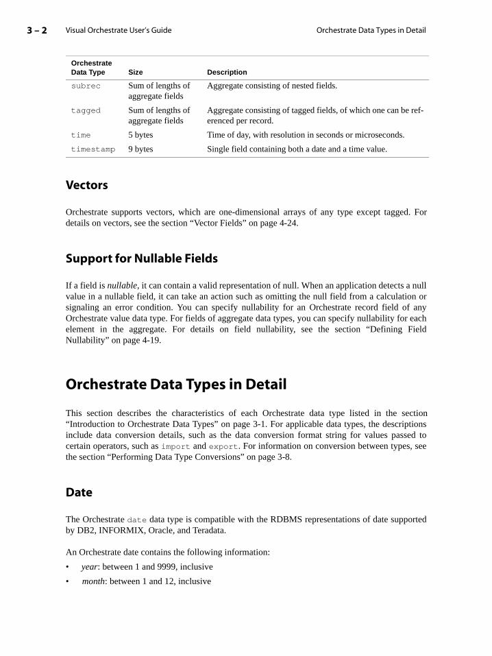
Visual Orchestrate User’s Guide3 – 2 Orchestrate Data Types in Detail
nullon or anyr eachield
sectioniptionsssed toee
rted
Vectors
Orchestrate supports vectors, which are one-dimensional arrays of any type except tagged. Fordetails on vectors, see the section “Vector Fields” on page 4-24.
Support for Nullable Fields
If a field is nullable, it can contain a valid representation of null. When an application detects avalue in a nullable field, it can take an action such as omitting the null field from a calculatisignaling an error condition. You can specify nullability for an Orchestrate record field ofOrchestrate value data type. For fields of aggregate data types, you can specify nullability foelement in the aggregate. For details on field nullability, see the section “Defining FNullability” on page 4-19.
Orchestrate Data Types in Detail
This section describes the characteristics of each Orchestrate data type listed in the “Introduction to Orchestrate Data Types” on page 3-1. For applicable data types, the descrinclude data conversion details, such as the data conversion format string for values pacertain operators, such as import and export. For information on conversion between types, sthe section “Performing Data Type Conversions” on page 3-8.
Date
The Orchestrate date data type is compatible with the RDBMS representations of date suppoby DB2, INFORMIX, Oracle, and Teradata.
An Orchestrate date contains the following information:
• year: between 1 and 9999, inclusive
• month: between 1 and 12, inclusive
subrec Sum of lengths of aggregate fields
Aggregate consisting of nested fields.
tagged Sum of lengths of aggregate fields
Aggregate consisting of tagged fields, of which one can be ref-erenced per record.
time 5 bytes Time of day, with resolution in seconds or microseconds.
timestamp 9 bytes Single field containing both a date and a time value.
Orchestrate Data Type Size Description

Orchestrate Data Types 3 – 3Visual Orchestrate User’s Guide
ange 1
4713 count
tination that if
d to agth younents to
to theeric
ro indi-
rext
ompo-
• day of month: between 1 and 31, inclusive
You can also specify a date using two forms of the Julian representation:
• Julian date uses two components to define a date: a year and the day of the year in the rto 366, inclusive.
• Julian day contains a single component specifying the date as the number of days fromBCE January 1, 12:00 hours (noon) GMT. For example, January 1, 1998 is Julian day2,450,815.
Data Conversion Format for a DateBy default, an Orchestrate operator interprets a string containing a date value yyyy-mm-dd. If thedate argument does not include a day, the operator sets it to the first of the month in the desfield. If the date does not include either the month or the day, they default to January 1. Notethe date includes a day of the month, it must also include a month.
If you wish to specify a non-default format, you can pass the operator an optional format stringdescribing the format of the date argument. In a format string for a source string convertedate, you must zero-pad the date components (date, month, and year) to the component lenspecify. For a destination string that receives a date, Orchestrate zero-pads the date compothe specified length.
The following list describes the components that you can use in the format string. In additionrequired portions of the date components described below, you can also include non-numcharacters is as separators or delimiters.
• %dd: A two-digit day of the month (range of 1 - 31).
• %ddd: Day of year in three-digit form (range of 1 - 366).
• %mm: A two-digit month (range of 1 - 12).
• %<year_cutoff>yy: A two-digit year derived from yy and a four-digit year cutoff.
<year_cutoff> specifies the starting year of the century in which the specified yy falls. Youcan specify any four-digit year as <year_cutoff>. Then, yy is interpreted as the low-ordetwo digits of the year that is the same as or greater than the year cutoff. For example, tcate that the year passed as 31 represents 1931, you could specify the <year_cutoff> of1930. If you pass a format string with a <year_cutoff> of 1930 and the corresponding yeain the date string argument is 29, Orchestrate interprets that year as 2029, which is the nyear ending in 29 that is after the <year_cutoff>.
• %yy: A two-digit year derived from a default year cutoff of 1900. For example, using theyy
format for a year of 42 results in its interpretation as 1942.
• %yyyy: A four-digit year.
Note: Each component of the date format string must start with the percent symbol (%).
Following are examples of complete date format strings using one or more of the possible cnents:
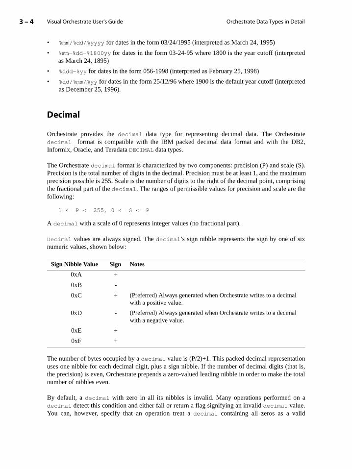
Visual Orchestrate User’s Guide3 – 4 Orchestrate Data Types in Detail
ted
eted
rateB2,
(S).ximumrising the
ix
ionat is,
he total
a
• %mm/%dd/%yyyy for dates in the form 03/24/1995 (interpreted as March 24, 1995)
• %mm-%dd-%1800yy for dates in the form 03-24-95 where 1800 is the year cutoff (interpreas March 24, 1895)
• %ddd-%yy for dates in the form 056-1998 (interpreted as February 25, 1998)
• %dd/%mm/%yy for dates in the form 25/12/96 where 1900 is the default year cutoff (interpras December 25, 1996).
Decimal
Orchestrate provides the decimal data type for representing decimal data. The Orchestdecimal format is compatible with the IBM packed decimal data format and with the DInformix, Oracle, and Teradata DECIMAL data types.
The Orchestrate decimal format is characterized by two components: precision (P) and scalePrecision is the total number of digits in the decimal. Precision must be at least 1, and the maprecision possible is 255. Scale is the number of digits to the right of the decimal point, compthe fractional part of the decimal. The ranges of permissible values for precision and scale arefollowing:
1 <= P <= 255, 0 <= S <= P
A decimal with a scale of 0 represents integer values (no fractional part).
Decimal values are always signed. The decimal’s sign nibble represents the sign by one of snumeric values, shown below:
The number of bytes occupied by a decimal value is (P/2)+1. This packed decimal representatuses one nibble for each decimal digit, plus a sign nibble. If the number of decimal digits (ththe precision) is even, Orchestrate prepends a zero-valued leading nibble in order to make tnumber of nibbles even.
By default, a decimal with zero in all its nibbles is invalid. Many operations performed ondecimal detect this condition and either fail or return a flag signifying an invalid decimal value.You can, however, specify that an operation treat a decimal containing all zeros as a valid
Sign Nibble Value Sign Notes
0xA +
0xB -
0xC + (Preferred) Always generated when Orchestrate writes to a decimal with a positive value.
0xD - (Preferred) Always generated when Orchestrate writes to a decimal with a negative value.
0xE +
0xF +
Orchestrate Data Types 3 – 5Visual Orchestrate User’s Guide
:
d
t as an
inging iss not fit
the
oint. to ther thength
metic
representation of the value 0. In that case, Orchestrate treats the decimal as valid and performs theoperation.
A decimal’s available range, or its maximum and minimum possible values, is based on its preci-sion and scale. The equation for determining a decimal’s upper and lower bounds is the following
Note that this is an exclusive range, so that the decimal will always be less than the maximum angreater than the minimum. Thus, if P = 4 and S = 2, the range is - 99.99 <= decimal <= 99.99 (it isnot -100.00 <= decimal <= 100.00).
String Assignment and Conversion for DecimalsOrchestrate lets you assign a string to a decimal and a decimal to a string. The two mostlikely situations for such assignments are performing an import or export and using a data seinput to an operator.
When a string is assigned to a decimal, the string is interpreted as a decimal value. Stringsassigned to decimals must be in the form:
[+/-]ddd[.ddd]
where items in brackets are optional.
By default, Orchestrate treats the string as null-terminated However, you can also specify a strlength. Orchestrate ignores leading or trailing white space in the string. Range checkperformed during the assignment, and a requirement failure occurs if the assigned value doewithin the decimal's available range.
You can also assign a decimal to a string. The destination string represents the decimal in following format:
[+/-]ddd.[ddd]
A leading space or minus sign is written, followed by the decimal digits and a decimal pLeading and trailing zeros are not suppressed. A fixed-length string is padded with spacesfull length of the string. A fixed-length string must be precision + 2 bytes long (one byte foleading sign indicator and one byte for the decimal point). A range failure occurs if a fixed-lestring field is not large enough to hold the decimal.
Floating-Point
Orchestrate defines single- and double-precision floating-point data types. All standard arithand conditional operations are supported for these floating-point data types.
range 10± P S–( )=

Visual Orchestrate User’s Guide3 – 6 Orchestrate Data Types in Detail
Integers
Orchestrate defines signed and unsigned, 8-, 16-, 32-, and 64-bit integer data types. All standardarithmetic and conditional operations are supported by these data types.
Raw
The Orchestrate raw data type is a collection of untyped bytes, similar to the void data type in theC programming language. A raw in Orchestrate always contains a length, rather than a nullterminator.
String
An Orchestrate string field always specifies a length and does not include a null terminator.
Subrecord
You define nested field definitions, or subrecords, with the aggregate data type subrec. Asubrecord itself does not define any storage; instead, the fields of the subrecord define storage. Thefields in a subrecord can be of any data type, including tagged.
Tagged
You define tagged aggregate fields (similar to C unions) with the aggregate data type tagged.Defining a record with a tagged aggregate allows each record of a data set to have a different datatype for the tagged field. When your application writes to a field in a tagged aggregate field,Orchestrate updates the tag, which identifies it as having type of the field that is referenced.
The data type of a tagged aggregate subfields can be of any Orchestrate data type except tagged orsubrec.
Time
The time data type uses a 24-hour representation, with either a one-second resolution or amicrosecond resolution. The Orchestrate time data type is compatible with most RDBMSrepresentations of time.
Valid times are in the range 00:00:00.000000 to 23:59:59.999999. Incrementing a time value of23:59:59.999999 wraps the time around to 00:00:00.000000.
Orchestrate Data Types 3 – 7Visual Orchestrate User’s Guide
ent.
y
t
The time data type contains no information regarding time zone. In Orchestrate operations, alltime values are treated as if they are in the same time zone.
Data Conversion Format for a Time ValueBy default, an Orchestrate operator interprets a string containing a time value as hh:nn:ss, wherehh is the hour, nn is the minute (so indicated to avoid confusion with the month value in the dateformat), and ss is the second.
If you wish to specify a non-default format, you can pass the operator an optional format stringdescribing the format of the time argument. In a format string for a source string converted to atime, the time components (hour, minutes, and seconds) must be zero-padded to the characterlength specified by the format string. For a destination string that receives a time, Orchestratezero-pads the time components to the specified length.
The possible components of the format string are:
• %hh: A two-digit hours component.
• %nn: A two-digit minute component (nn represents minutes because mm is used for the monthof date).
• %ss: A two-digit seconds component.
• %ss.N: A two-digit seconds plus fractional part where N is the number of fractional digits witha maximum value of 6. If N is 0, no decimal point is printed as part of the seconds componTrailing zeros are not suppressed.
Note: Each component of the time format string must start with the percent symbol (%).
For example, you could specify a format string of %hh:%nn to specify that the string contains onlan hour and minutes component. You could also specify the format as %hh:nn:ss.4 to specifythat the string also contains the seconds to four decimal places.
Timestamp
A timestamp includes both a date, as defined by the Orchestrate date data type, and a time, asdefined by the time data type. The Orchestrate timestamp data type is compatible with mosRDBMS representations of a timestamp.
Data Conversion Format for a Timestamp ValueBy default, an Orchestrate operator interprets a string containing a timestamp value as the follow-ing:
yyyy-mm-dd hh:nn:ss
Note that the month is represented by mm, while minutes are represented by nn. Also note therequired space between the date and time parts of the timestamp.
Visual Orchestrate User’s Guide3 – 8 Performing Data Type Conversions
on Thescribed
ma must
ields in
ndingefault
n field.
ust use
ysi-tails on
To specify a non-default conversion format for a timestamp, you use a format string thatcombines the format strings for date (see the section “Data Conversion Format for a Date” page 3-3) and time (see the section “Data Conversion Format for a Time Value” on page 3-7).conversion format you specify must be valid for both the date and the time segments, as dein the applicable sections.
Performing Data Type Conversions
This section describes the following topics:
• “Rules for Orchestrate Data Type Conversions” on page 3-8
• “Summary of Orchestrate Data Type Conversions” on page 3-9
• “Example of Default Type Conversion” on page 3-10
• “Example of Type Conversion with modify” on page 3-10
• “Data Type Conversion Errors” on page 3-11
Rules for Orchestrate Data Type Conversions
For a data set to be used as input to or output from an Orchestrate operator, its record schebe compatible with the interface for that operator, as follows:
• The names of the data set’s fields must be identical to the names of the corresponding fthe operator interface.
• The data type of each field in the data set must be compatible with that of the correspofield in the operator interface. Data types are compatible if Orchestrate can perform a ddata type conversion, translating a value in a source field to the data type of a destinatio
If there are any discrepancies in field names, you must use the modify operator to change the fieldnames for your data set. If your data set has any fields with incompatible data types, you mthe modify operator to convert those types so they are compatible.
Note: For all built-in Orchestrate operators (except import/export of flat files), the internal, phcal representation of Orchestrate data types is handled transparently by Orchestrate. For deusing the import and export operators, see the Orchestrate User’s Guide: Operators.
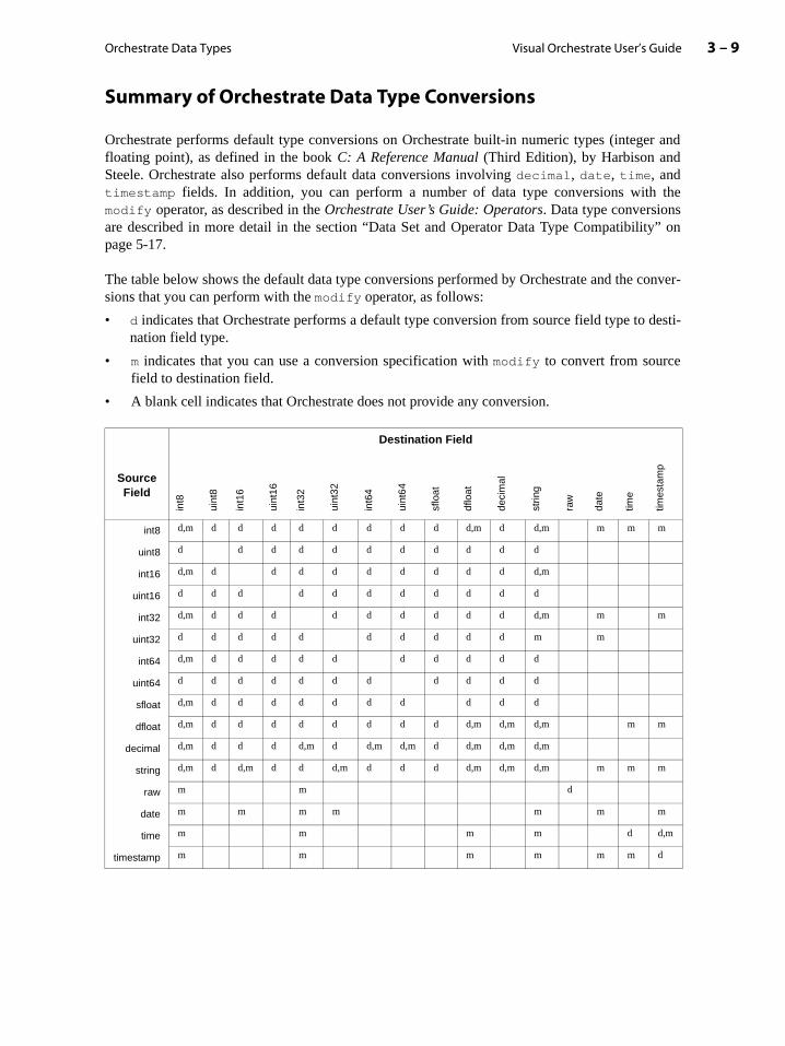
Orchestrate Data Types 3 – 9Visual Orchestrate User’s Guide
ty” on
conver-
desti-
Summary of Orchestrate Data Type Conversions
Orchestrate performs default type conversions on Orchestrate built-in numeric types (integer andfloating point), as defined in the book C: A Reference Manual (Third Edition), by Harbison andSteele. Orchestrate also performs default data conversions involving decimal, date, time, andtimestamp fields. In addition, you can perform a number of data type conversions with themodify operator, as described in the Orchestrate User’s Guide: Operators. Data type conversionsare described in more detail in the section “Data Set and Operator Data Type Compatibilipage 5-17.
The table below shows the default data type conversions performed by Orchestrate and the sions that you can perform with the modify operator, as follows:
• d indicates that Orchestrate performs a default type conversion from source field type tonation field type.
• m indicates that you can use a conversion specification with modify to convert from sourcefield to destination field.
• A blank cell indicates that Orchestrate does not provide any conversion.
Destination Field
Source Field
int8
uint
8
int1
6
uint
16
int3
2
uint
32
int6
4
uint
64
sflo
at
dflo
at
deci
mal
strin
g
raw
date
time
times
tam
p
int8 d,m d d d d d d d d d,m d d,m m m m
uint8 d d d d d d d d d d d
int16 d,m d d d d d d d d d d,m
uint16 d d d d d d d d d d d
int32 d,m d d d d d d d d d d,m m m
uint32 d d d d d d d d d d m m
int64 d,m d d d d d d d d d d
uint64 d d d d d d d d d d d
sfloat d,m d d d d d d d d d d
dfloat d,m d d d d d d d d d,m d,m d,m m m
decimal d,m d d d d,m d d,m d,m d d,m d,m d,m
string d,m d d,m d d d,m d d d d,m d,m d,m m m m
raw m m d
date m m m m m m m
time m m m m d d,m
timestamp m m m m m m d
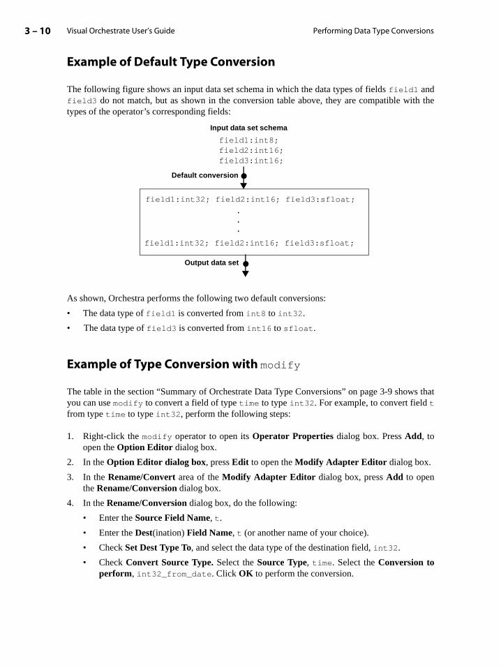
Visual Orchestrate User’s Guide3 – 10 Performing Data Type Conversions
ws that
Example of Default Type Conversion
The following figure shows an input data set schema in which the data types of fields field1 andfield3 do not match, but as shown in the conversion table above, they are compatible with thetypes of the operator’s corresponding fields:
As shown, Orchestra performs the following two default conversions:
• The data type of field1 is converted from int8 to int32.
• The data type of field3 is converted from int16 to sfloat.
Example of Type Conversion with modify
The table in the section “Summary of Orchestrate Data Type Conversions” on page 3-9 shoyou can use modify to convert a field of type time to type int32. For example, to convert field t
from type time to type int32, perform the following steps:
1. Right-click the modify operator to open its Operator Properties dialog box. Press Add, toopen the Option Editor dialog box.
2. In the Option Editor dialog box, press Edit to open the Modify Adapter Editor dialog box.
3. In the Rename/Convert area of the Modify Adapter Editor dialog box, press Add to openthe Rename/Conversion dialog box.
4. In the Rename/Conversion dialog box, do the following:
• Enter the Source Field Name, t.
• Enter the Dest(ination) Field Name, t (or another name of your choice).
• Check Set Dest Type To, and select the data type of the destination field, int32.
• Check Convert Source Type. Select the Source Type, time. Select the Conversion toperform, int32_from_date. Click OK to perform the conversion.
field1:int8;field2:int16;field3:int16;
Input data set schema
Default conversion
Output data set
.
.
.
field1:int32; field2:int16; field3:sfloat;
field1:int32; field2:int16; field3:sfloat;

Orchestrate Data Types 3 – 11Visual Orchestrate User’s Guide
ersion
As shown in the conversion table above, there is no default conversion from time to uint64. How-ever, there is a default conversion from int32 to uint64, and there is an explicit (with modify)conversion from int32 to uint64. Therefore, you can effect a default conversion to convert fieldt from type time to type uint64. To do so, use the Rename/Conversion dialog box, described inStep 4. above. Enter the Source Field Name, t. Enter the Dest Field Name of your choice. In theSet Dest Type To field, enter uint64. Do not check Convert Source Type. Press OK. Orchestrateconverts the type from time to int32, and then from int32 to uint64.
Data Type Conversion Errors
A error results when any Orchestrate operator is unable to perform a default data type conversion.See “Data Type Conversion Errors and Warnings” on page 5-17 for details on data type converrors and warnings and on how to prevent them.

Visual Orchestrate User’s Guide3 – 12 Performing Data Type Conversions
4 – 1Visual Orchestrate User’s Guide
d in thatas is a
4: Orchestrate Data Sets
Orchestrate data sets contain the data processed by an Orchestrate application. Orchestrateoperators take data sets as input, process all records of the input data set(s), and write theirresults to output data sets.
This chapter introduces data sets by defining their structure and the two types of data setsused by Orchestrate. It also explains how to use data sets with operators.
This chapter contains the following sections:
• “Orchestrate Data Sets” on page 4-1
• “Using Visual Orchestrate with Data Sets” on page 4-7
• “Defining a Record Schema” on page 4-16
• “Representation of Disk Data Sets” on page 4-32
Note: To manage Orchestrate persistent data sets, use the Orchestrate administration utilityorchadmin, which is described in the Orchestrate Installation and Administration Manual.
Orchestrate Data Sets
This section covers data set structure, record schemas, field data types, use of data sets withoperators, and the different types of data sets.
Data Set Structure
A data set consists of a one-dimensional array (vector) of records. The fundamentals of record-based data are described in the section “Orchestrate Data Sets” on page 1-5. As describechapter, fields of some types, such as int8, are of fixed length. Fields of other types, such string, can be of variable length. A record that defines one or more variable-length fieldsvariable-length record.

Visual Orchestrate User’s Guide4 – 2 Orchestrate Data Sets
could
in aw andd each
ema” onestrate
sists orprop-
The following figure shows a sample data set and the format of its variable-length record definition,which contains two variable-length fields of type string:
An example of an appropriate use of this variable-length record format is a mailing list. In that case,each record in the data set would hold the data for one person. One variable-length string fieldcould contain the person’s name, and the second field the address. A 32-bit integer fieldcontain a key for sorting the records.
Another kind of data set has a fixed-length record layout, similar to a normalized tableRelational Database Management System (RDBMS). Normalized tables have a regular rocolumn layout. In the figure below, each row of the table corresponds to a single record, ancolumn corresponds to the same fixed-length field in every record:
Record Schemas
This section describes the data set schema, introduced in the section “The Orchestrate Schpage 1-6. See the chapter “Orchestrate Data Types” for fundamental information on Orchdata types.
A schema describes the prototypical record in a data set or operator interface. A schema cona record-level property list and a description of each field in the record. Specific record-level erties are described in the chapter on import/export properties in the OrchestrateUser’s Guide:Operators.
Record Record Record Record
Variable-length record
string string int32
. . .
Data set
.
.
.
Columns represent fields
Data set of fixed-length records
Rows represent records

Orchestrate Data Sets 4 – 3Visual Orchestrate User’s Guide
ield
ata set.rts mostexport
ram:
fining
ke data can alsorators,
The schema describes each field with the following information:
• An identifier (field name)
• A data type (for some types, parameterized)
• For string and raw fields, an optional length specification
• For a vector field, an optional length
• Field-level properties, such as the nullability specification (see the section “Defining FNullability” on page 4-19)
A fundamental use of a record schema is to describe the data for import into an Orchestrate dOrchestrate’s record schema can describe the data layout of any RDBMS table, and it suppoCOBOL records formats, including repeating substructures. See the chapter on the import/utility in the Orchestrate User’s Guide: Operators for more information on import and export.
In the following figure, a data set’s record schema is shown in a fragment of a data-flow diag
In this figure, the record schema for the input data set consists of five fields:
• a: A 32-bit integer
• b: A 10-element vector of 32-bit integers
• c: A nullable 16-bit integer
• d: A single-precision floating point value
• e: A variable-length string
See the section “Defining a Record Schema” on page 4-16 for more information on deschemas.
Using Data Sets with Operators
Orchestrate operators, introduced in the section “Orchestrate Operators” on page 1-9, can tasets or data files as input, and can produce data sets or data files as output. Some operatorsuse RDBMS tables as input or output. For extensive information on using Orchestrate opesee the chapter “Orchestrate Operators”.
a:int32;b[10]:int32;c:nullable int16;d:sfloat;e:string
Operator 1
Input data set schema
Operator 2
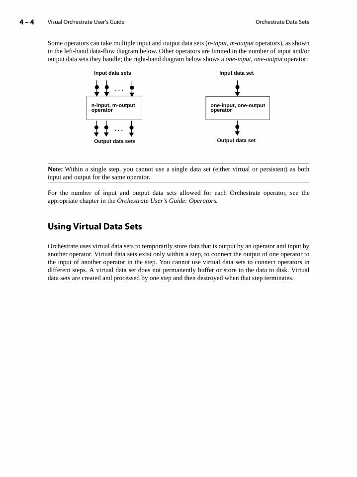
Visual Orchestrate User’s Guide4 – 4 Orchestrate Data Sets
Some operators can take multiple input and output data sets (n-input, m-output operators), as shownin the left-hand data-flow diagram below. Other operators are limited in the number of input and/oroutput data sets they handle; the right-hand diagram below shows a one-input, one-output operator:
Note: Within a single step, you cannot use a single data set (either virtual or persistent) as bothinput and output for the same operator.
For the number of input and output data sets allowed for each Orchestrate operator, see theappropriate chapter in the Orchestrate User’s Guide: Operators.
Using Virtual Data Sets
Orchestrate uses virtual data sets to temporarily store data that is output by an operator and input byanother operator. Virtual data sets exist only within a step, to connect the output of one operator tothe input of another operator in the step. You cannot use virtual data sets to connect operators indifferent steps. A virtual data set does not permanently buffer or store to the data to disk. Virtualdata sets are created and processed by one step and then destroyed when that step terminates.
. . .
. . .
Input data sets Input data set
Output data sets Output data set
n-input, m-output operator
one-input, one-output operator

Orchestrate Data Sets 4 – 5Visual Orchestrate User’s Guide
The following data-flow model shows a step that uses two virtual data sets to connect threeoperators:
Step 1
Operator 1
Operator 2
Operator 3
Virtual data set 1
Virtual data set 2
inFile.data
outFile.data

Visual Orchestrate User’s Guide4 – 6 Orchestrate Data Sets
Using Persistent Data Sets
Persistent data sets are stored to a disk file, so that the data processed by a step is preserved after thestep terminates. You can use persistent data sets to share data between two or more steps, as shownbelow:
Step 1 saves the data set output from Operator 2 and uses it as the input to Step 2. These two stepscould be part of a single executable file, or each could be part of a separate executable file.
The example above uses the Orchestrate copy operator to create two copies of the data set outputof Operator 2: a virtual data set passed to Operator 3 and a persistent data set used as input toOperator 4. The copy operator takes a single data set as input and produces any number of copiesof the input data set as output.
Note: A persistent data set cannot serve as both an input and an output in a single step. The reasonfor this restriction is that a file cannot be open simultaneously for reading and for writing.
copy operator
Operator 1
Operator 2
Step 1
Operator 3
Step 2
Operator 4
Operator 5
Operator 6
Virtual data set 4
Virtual data set 5
Virtual data set 1
Persistent data set 1
Persistent data set 2
Persistent data set 3
Virtual data set 2
Virtual data set 3
inFile.data
copyDS.ds
out3DS.dsout6DS.ds
Orchestrate Data Sets 4 – 7Visual Orchestrate User’s Guide
tioning
erefore,ete set
he set. See
al data
Importing Data into a Data Set
In many Orchestrate applications, the first operation is to read data from a disk file and to convertthe data to an Orchestrate data set. Then, Orchestrate can begin processing the data in parallel,including partitioning the data set. When processing is complete, your application can export thedata set to a disk file in the same format as the input file for the application.
The Orchestrate import/export utility lets you import a data file into Orchestrate as a data set andexport a data set to a file. See the chapters on the import and export operators in the OrchestrateUser’s Guide: Operators for more information.
Partitioning a Data Set
Partitioning divides a data set into multiple pieces, or partitions. Each processing node in yoursystem then performs an operation in parallel on an individual partition of the data set rather thanon the entire data set, resulting in much higher throughput than a using a single-processor system.
To implement partitioning, Orchestrate divides a data set by records. See the chapter “Partiin Orchestrate” for more information on how Orchestrate partitions data sets.
Copying and Deleting Persistent Data Sets
Orchestrate represents a single data set as multiple files on multiple processing nodes. Thyou cannot use the standard UNIX commands rm to delete or cp to copy a persistent data set. Sethe section “Representation of Disk Data Sets” on page 4-32 for more information on darepresentation.
Orchestrate provides the orchadmin utility to manipulate data sets. This utility recognizes tlayout of a persistent data set and accesses all data files to copy or delete the persistent datathe Orchestrate Installation and Administration Manual for a detailed discussion of orchadmin.
Using Visual Orchestrate with Data Sets
This section describes how to use Visual Orchestrate to manipulate both persistent and virtusets. Included below are the following sections:
• “Working with Persistent Data Sets” on page 4-8
• “Working with Virtual Data Sets” on page 4-12
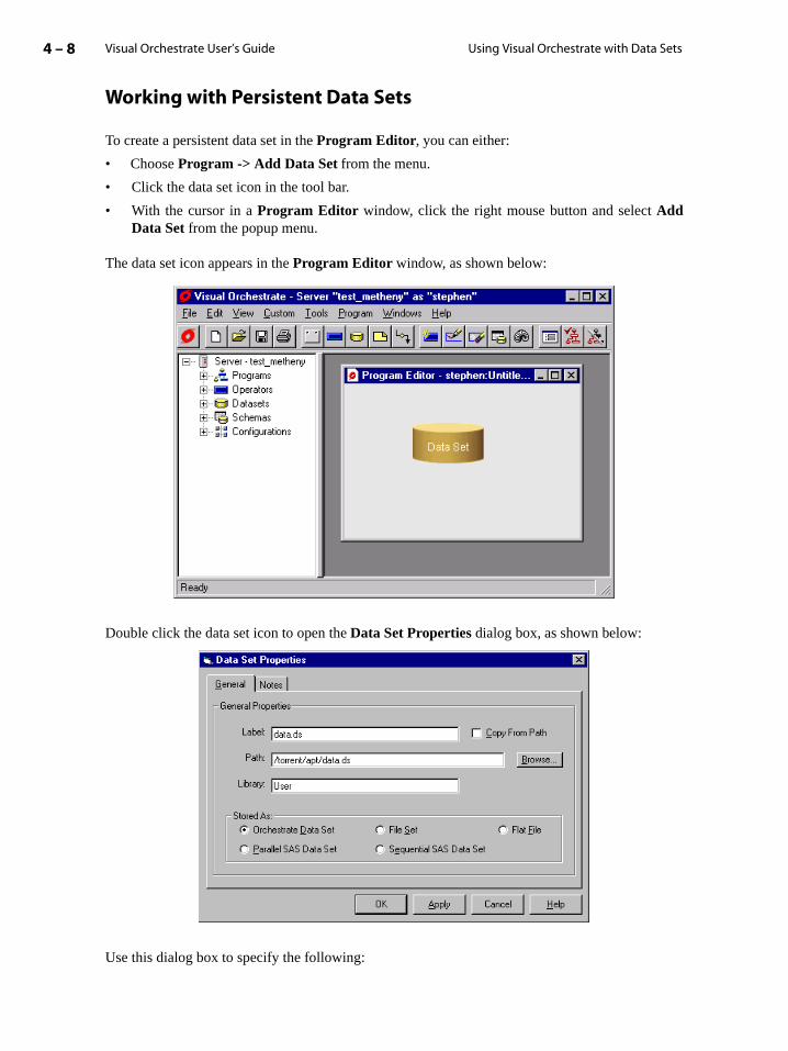
Visual Orchestrate User’s Guide4 – 8 Using Visual Orchestrate with Data Sets
Working with Persistent Data Sets
To create a persistent data set in the Program Editor, you can either:
• Choose Program -> Add Data Set from the menu.
• Click the data set icon in the tool bar.
• With the cursor in a Program Editor window, click the right mouse button and select AddData Set from the popup menu.
The data set icon appears in the Program Editor window, as shown below:
Double click the data set icon to open the Data Set Properties dialog box, as shown below:
Use this dialog box to specify the following:

Orchestrate Data Sets 4 – 9Visual Orchestrate User’s Guide
ndi-
on on
on
d of theou can
The Label of the data set in the Program Editor window.
The Pathname of the data set’s descriptor file. The descriptor file contains a list of all the ividual data files, stored across your parallel machine, that contain the data set records.
See the section “Representation of Disk Data Sets” on page 4-32 for more informatidata set layout.
The Library name for the data set. The library corresponds to the entry in the View Window,under Data Set, containing the data set name.
Stored As. Choose the representation of the data set as either an Orchestrate Data Set(default), a File Set, a Flat File, or either of the two SAS representations. See the sectionthe import and export operators in the Orchestrate User’s Guide: Operators for more infor-mation on representations of data sets.
After you create the data set, you create a link to connect the data set to an operator as either aninput or output data set. This procedure is described in the following two sections:
• “Connecting a Persistent Data Set as Input” on page 4-9
• “Connecting a Persistent Data Set as Output” on page 4-11
Connecting a Persistent Data Set as InputTo connect a persistent data set as an input to an operator, create a link and attach one enlink to the data set and the other end of the link to the input of an operator. To create a link, ydo any one of the following:
• Choose Program -> AddLink from the menu.
• Click the link icon in the tool bar.
• With the cursor in a Program Editor window, click the right mouse button and select AddLink from the popup menu.
The following figure shows a data set connected to an operator by a link:
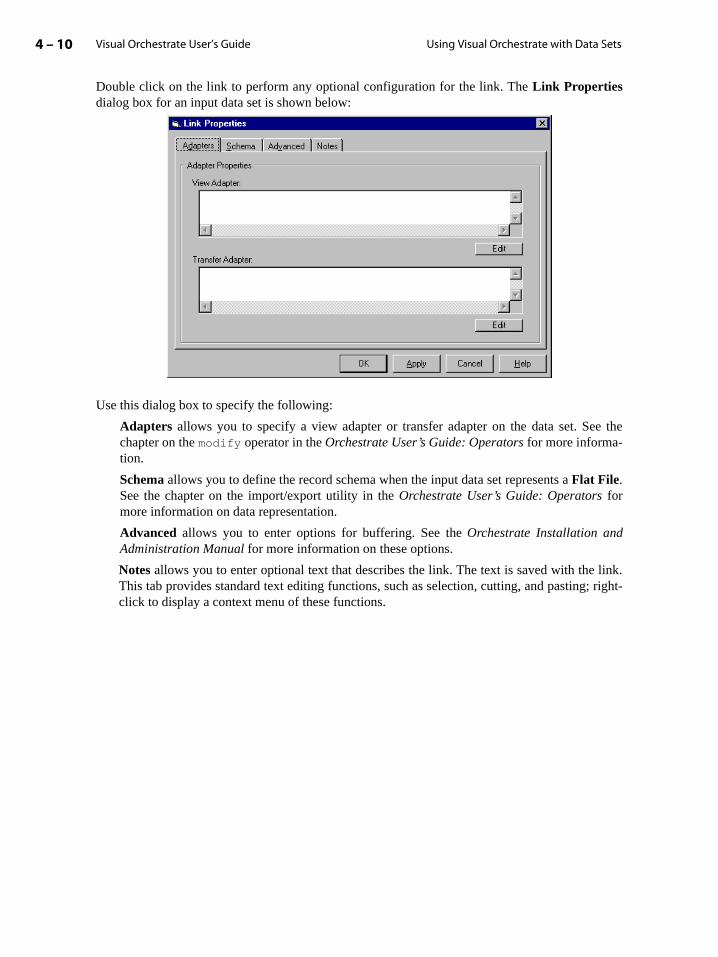
Visual Orchestrate User’s Guide4 – 10 Using Visual Orchestrate with Data Sets
Double click on the link to perform any optional configuration for the link. The Link Propertiesdialog box for an input data set is shown below:
Use this dialog box to specify the following:
Adapters allows you to specify a view adapter or transfer adapter on the data set. See thechapter on the modify operator in the Orchestrate User’s Guide: Operators for more informa-tion.
Schema allows you to define the record schema when the input data set represents a Flat File.See the chapter on the import/export utility in the Orchestrate User’s Guide: Operators formore information on data representation.
Advanced allows you to enter options for buffering. See the Orchestrate Installation andAdministration Manual for more information on these options.
Notes allows you to enter optional text that describes the link. The text is saved with the link.This tab provides standard text editing functions, such as selection, cutting, and pasting; right-click to display a context menu of these functions.

Orchestrate Data Sets 4 – 11Visual Orchestrate User’s Guide
s. Byisting
“Con-
Connecting a Persistent Data Set as OutputTo connect the data set as an output, create a link and attach one end of the link to the data set andthe other end of the link to the output from an operator.
Double click on the link to perform any optional configuration for the link. The Link Propertiesdialog box for an output data set is shown below:
This dialog box contains the following tabs:
Overwrite tab to control Orchestrate’s action when the output data set already existdefault, Orchestrate signals an error and aborts your application when writing to an exdata set. This prevents you from accidentally overwriting data.
You can accept the default of Signal an error, choose to Overwrite it, or choose to Appenddata to it. See the next section for more information on append.
Schema tab to explicitly define the record schema for the output data set.
Constraints tab to control where the data set is written on your system. See the chapter straints” for more information.

Visual Orchestrate User’s Guide4 – 12 Using Visual Orchestrate with Data Sets
“Thening
Thist-click
executeddition,ting data
tains isa to themay beg the
by an store it
set. To
pending
Visual
Advanced tab for setting preserve-partitioning flag and buffering options. See the section Preserve-Partitioning Flag” on page 8-11 for more information on the preserve-partitioflag.
Notes tab for entering optional text that describes the link. The text is saved with the link.tab provides standard text editing functions, such as selection, cutting, and pasting; righto display a context menu of these functions.
Appending Data to an Existing Data SetOrchestrate allows you to append data to an existing data set. The appending operator mustin a separate step from the operator performing the write that first created the data set. In arecords appended to an existing data set must have an identical record schemas as the exisset.
When a persistent data set is created and first written to disk, the number of partitions it conequal to the number of instances of the operator that creates it. When you later append datdata set, the number of processing nodes on which the appending operator executes different from the number of partitions in the existing data set. Also, the data files containinappended records can reside on disk drives other than those holding the original data.
For example, if a data set was originally created with eight partitions, and is appended tooperator executing on four processing nodes, Orchestrate repartitions the appending data toas eight partitions.
The state of a data set’s repartitioning flag is saved to disk along with the records of the dataprevent Orchestrate from repartitioning the data set, you can set the repartitioning flag to preserveThen, when you append data to that data set, Orchestrate creates one instance of the apoperator for each partition of the data set.
Working with Virtual Data Sets
Virtual data sets connect the output of one operator to the input of another operator. In Orchestrate, you use a link to implement a virtual data set.
To create a link, you can either:
• Choose Program -> Add Link from the menu.
• Click the link icon in the tool bar.
• With the cursor in a Program Editor window, click the right mouse button and select AddLink from the popup menu.
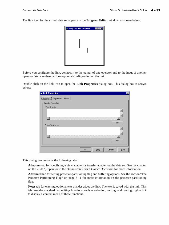
Orchestrate Data Sets 4 – 13Visual Orchestrate User’s Guide
“Thening
Thist-click
The link icon for the virtual data set appears in the Program Editor window, as shown below:
Before you configure the link, connect it to the output of one operator and to the input of anotheroperator. You can then perform optional configuration on the link.
Double click on the link icon to open the Link Properties dialog box. This dialog box is shownbelow:
This dialog box contains the following tabs:
Adapters tab for specifying a view adapter or transfer adapter on the data set. See the chapteron the modify operator in the Orchestrate User’s Guide: Operators for more information.
Advanced tab for setting preserve-partitioning flag and buffering options. See the section Preserve-Partitioning Flag” on page 8-11 for more information on the preserve-partitioflag.
Notes tab for entering optional text that describes the link. The text is saved with the link.tab provides standard text editing functions, such as selection, cutting, and pasting; righto display a context menu of these functions.

Visual Orchestrate User’s Guide4 – 14 Using Visual Orchestrate with Data Sets
Using the Data Set Viewer
The Visual Orchestrate Data Set Viewer lets you display information about an Orchestratepersistent data set. You access the utility by choosing the menu command Tools -> Data SetViewer.
1. Choose Tools -> Data Set Viewer from the Visual Orchestrate menu. This opens the followingdialog box that you use to select a persistent data set you want information on:
2. Choose the data set and click OK to open the following dialog box displaying informationabout the data set:
View data

Orchestrate Data Sets 4 – 15Visual Orchestrate User’s Guide
3. You can dump data set records by clicking on the View Data button. This opens the followingdialog box:
Specify the records you want to display, and then click the View button.
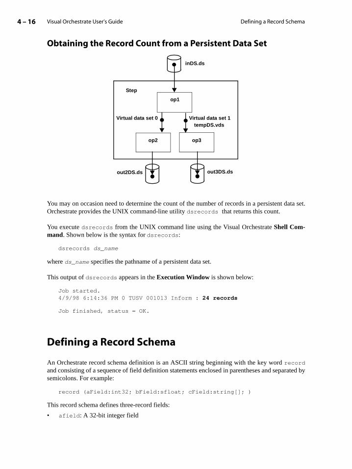
Visual Orchestrate User’s Guide4 – 16 Defining a Record Schema
Obtaining the Record Count from a Persistent Data Set
You may on occasion need to determine the count of the number of records in a persistent data set.Orchestrate provides the UNIX command-line utility dsrecords that returns this count.
You execute dsrecords from the UNIX command line using the Visual Orchestrate Shell Com-mand. Shown below is the syntax for dsrecords:
dsrecords ds_name
where ds_name specifies the pathname of a persistent data set.
This output of dsrecords appears in the Execution Window is shown below:
Job started.4/9/98 6:14:36 PM 0 TUSV 001013 Inform : 24 records
Job finished, status = OK.
Defining a Record Schema
An Orchestrate record schema definition is an ASCII string beginning with the key word recordand consisting of a sequence of field definition statements enclosed in parentheses and separated bysemicolons. For example:
record (aField:int32; bField:sfloat; cField:string[]; )
This record schema defines three-record fields:
• afield: A 32-bit integer field
Step
op2
op1
op3
Virtual data set 1Virtual data set 0
inDS.ds
out3DS.dsout2DS.ds
tempDS.vds
Orchestrate Data Sets 4 – 17Visual Orchestrate User’s Guide
g your
5-8 for
e con-t of the on the
a of a
• bField: A single-precision (32-bit) floating-point field
• cField: A variable-length character string
Schema Definition Files
For use with the import, export, and generator operators, you can create a file containinschema definition. See the chapters for those operators in the Orchestrate User’s Guide: Operators.
You can include comments in schema definition files. The starting delimiter for a comment is adouble slash //, and the ending delimiter is a new-line. Note, however, that you cannot usecomments in schema definitions that you specify on the command line.
Field Accessors
You can retrieve information about a field, such as whether it is nullable, by calling functions on itsfield accessor. For information on declaring and using field accessors, see the Orchestrate/APTDeveloper’s Guide for information.
How a Data Set Acquires Its Record Schema
A data set acquires its record schema in one of the following three ways:
1. Import of the data set from an external representation. Often, the first action of an Orchestrateapplication is to import data and convert it to a data set. You define the record schema of theresultant data set at the time of the import. See the chapter on import in the OrchestrateUser’s Guide: Operators for more information.
2. A write to the data set by an Orchestrate operator. A data set with no schema inherits the outputinterface schema of the operator that writes to it. This is the most common way for an outputdata set to obtain a schema. See the section “Output Data Sets and Operators” on pagemore information.
3. A read from an RDBMS table by an RDBMS operator. On a read operation, Orchestratverts the table into an Orchestrate data set by reading both the data and the record layoutable. Orchestrate automatically creates a record schema for the new data set, basedinformation from the RDBMS table.
Note that on a write operation to an RDBMS table, Orchestrate converts the record schemdata set to the table layout of an RDBMS data set. See the Orchestrate User’s Guide: Opera-tors for specific information on how your RDBMS works with Orchestrate.
The following sections describe how to create record schemas, name record fields, specifynullability, and set record schema properties for each Orchestrate data type.
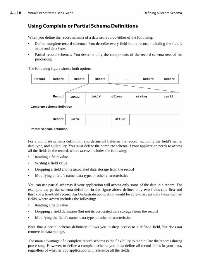
Visual Orchestrate User’s Guide4 – 18 Defining a Record Schema
ield’s
ded for
ame,access
rd. Fort andefined
es
duringr data,
Using Complete or Partial Schema Definitions
When you define the record schema of a data set, you do either of the following:
• Define complete record schemas: You describe every field in the record, including the fname and data type.
• Partial record schemas: You describe only the components of the record schema neeprocessing.
The following figure shows both options:
For a complete schema definition, you define all fields in the record, including the field’s ndata type, and nullability. You must define the complete schema if your application needs to all the fields in the record, where access includes the following:
• Reading a field value
• Writing a field value
• Dropping a field and its associated data storage from the record
• Modifying a field’s name, data type, or other characteristics
You can use partial schemas if your application will access only some of the data in a recoexample, the partial schema definition in the figure above defines only two fields (the firsthird) of a five-field record. An Orchestrate application would be able to access only those dfields, where access includes the following:
• Reading a field value
• Dropping a field definition (but not its associated data storage) from the record
• Modifying the field’s name, data type, or other characteristics
Note that a partial schema definition allows you to drop access to a defined field, but donotremove its data storage.
The main advantage of a complete record schema is the flexibility to manipulate the recordsprocessing. However, to define a complete schema you must define all record fields in youregardless of whether you application will reference all the fields.
. . . Record Record Record Record Record Record
Record
Record
Complete schema definition
Partial schema definition
int32
int32 dfloat
dfloatint16 int32string

Orchestrate Data Sets 4 – 19Visual Orchestrate User’s Guide
g a the null
bility
uses ad data
tage ofwever,s of the
Partial schemas allow you to define only the fields that you are interested in processing and toignore all other data in the records. However, Orchestrate cannot perform some types ofmanipulations on partial schema definitions, such as dropping unused fields from the record.
See the chapter on the import/export utility in the Orchestrate User’s Guide: Operators for moreinformation.
Naming Record Fields
In your Orchestrate record schema definition, all field names must conform to the following con-ventions:
• The name must start with a letter or underscore (_) character.
• The name can contain only alphanumeric and underscore characters.
• The name is case insensitive.
Field names can be any length.
Defining Field Nullability
If a field is nullable, it can hold null, which indicates that the field contains no data. In processinrecord, an operator can detect a null value and take the appropriate action, such as omittingfield from a calculation or signalling an error condition.
This section describes two different methods for representing nulls, and how to specify nullain an Orchestrate record schema.
Orchestrate Null RepresentationOrchestrate uses a single-bit flag to mark a field as null. If the field is a vector, Orchestratesingle bit for each element of the vector, so that a nullable vector can contain both valielements and null elements. This type of null support is called an indicated null representation.
Some other software packages implement null support with an in-band representation, whichdesignates as null a specific value, such a numeric field’s most negative value. The disadvanin-band null representation is that requires the user to treat an in-range value as a null. HoOrchestrate does allow you to process data that uses in-band null representation, by meanmodify operator (see the Orchestrate User’s Guide: Operators).
Defining Nullability in a Record SchemaIn creating a record schema, you mark a field as nullable by inserting the keyword nullableimmediately before the field’s data type. Any field defined without the nullable keyword is bydefault not nullable. The following sample record schema defines a nullable int32 and a nullabledfloat vector:

Visual Orchestrate User’s Guide4 – 20 Defining a Record Schema
ethere an
record (n:nullable int32; s[10]:nullable dfloat;)
Even though a field is by default non-nullable, you can use the not_nullable keyword to beexplicit, as shown below:
record (n:not_nullable int32;)
To make every field in a record schema nullable, you can specify nullable at the record level,with the following syntax:
record nullable (n:int32; m:int16; f:dfloat;)
Specifying nullability at the record level affects top-level fields only and does not affect nestedfields.
Nullability can be overridden for any field in the record by explicit use of not_nullable, asshown below:
record nullable (n:int32; m:not_nullable int16; f:dfloat;)
Nullability of Vectors and AggregatesVectors are nullable, and you can check for a null in each element of a nullable vector.
An aggregate (tagged or subrecord) is not itself nullable. However, you can specify nullability forthe fields of an aggregate that have types that are nullable. Nullability and aggregate is furtherdiscussed in the section “Vectors and Aggregates in Schema Definitions” on page 4-24.
Checking Null and NullabilityTo determine whether a field is nullable, you must check its nullability property. To check wha field is nullable, or whether a nullable field currently contains null, you must first declaraccessor for the field; see the Orchestrate/APT Developer’s Guide for information. Field accessorscan also provide other information, such as the length of a variable-length vector.
Using Value Data Types in Schema Definitions
This section describes how to use the Orchestrate value data types in record schema definitions,with a section for each data type. Each section includes examples of field definitions, and somesections describe required and optional properties for fields of the data type. Vectors are furtherdescribed in the section “Vectors and Aggregates in Schema Definitions” on page 4-24.
Date FieldsYou can include date fields, in a record schema, as shown in the following examples:
record (dateField1:date; ) // single daterecord (dateField2[10]:date; ) // 10-element date vector
Orchestrate Data Sets 4 – 21Visual Orchestrate User’s Guide
s:
use-
-, 32-,
. You
es:
record (dateField3[]:date; ) // variable-length date vectorrecord (dateField4:nullable date;) // nullable date
Decimal FieldsYou can include decimal fields in a record schema. To define a record field with data type deci-mal, you must specify the field’s precision, and you may optionally specify its scale, as follow
fieldname:decimal[precision, scale];
where:
• 1 <= precision (no maximum)
• 0 <= scale < precision
If the scale is not specified, it defaults to zero, indicating an integer value.
Examples of decimal field definitions:
record (dField1:decimal[12]; ) // 12-digit integerrecord (dField2[10]:decimal[15,3]; )// 10-element decimal vectorrecord (dField3:nullable decimal[15,3];) // nullable decimal
Floating-Point FieldsYou can include floating-point fields in a record schema. To define floating-point fields, youthe sfloat (single-precision) or dfloat (double-precision) data type, as in the following examples:
record (aSingle:sfloat; aDouble:dfloat; ) // float definitionsrecord (aSingle: nullable sfloat;) // nullable sfloatrecord (doubles[5]:dfloat;) // fixed-length vector of dfloatsrecord (singles[]:sfloat;) // variable-length vector sfloats
Integer FieldsYou can include integer fields in a record schema. To define integer fields, you use an 8-, 16or 64-bit integer data type (signed or unsigned), as shown in the following examples:
record (n:int32;) // 32-bit signed integerrecord (n:nullable int64;) // nullable, 64-bit signed integerrecord (n[10]:int16;) // fixed-length vector of 16-bit signed integerrecord (n[]:uint8;) // variable-length vector of 8-bit unsigned int
Raw FieldsYou can define a record field that is a collection of untyped bytes, of fixed or variable lengthgive the field data type raw. You can also specify a byte alignment value on a raw field, to satisfyrequirements of your system architecture or to optimize the speed of data access.
The definition for a raw field is similar to that of a string field, as shown in the following exampl

Visual Orchestrate User’s Guide4 – 22 Defining a Record Schema
perty
e
ngthh is not
ifferentth and field,
record (var1:raw[];) // variable-length raw fieldrecord (var2:raw;) // variable-length raw field; same as raw[]record (var3:raw[40];) // fixed-length raw fieldrecord (var4[5]:raw[40];)// fixed-length vector of raw fields// variable-length raw aligned on 8-byte boundary:record (var5:raw[align = 8];) // vector of fixed-length raw fields aligned on 4-byte boundary:record (var6[5]:raw[align = 4, length = 20];)
Variable-Length Raw FieldsWhen an Orchestrate operator writes to a variable-length raw field, it determines the field lengthand updates the field’s length prefix. When an operator reads from a variable-length raw field, itfirst reads the length prefix to determine the field’s length.
You can specify the maximum number of bytes allowed in the raw field with the optional promax, as shown in the example below:
record (var7:raw[max=80];)
If an application attempts to write more than max bytes to a raw field, Orchestrate writes only thfirst max bytes.
Fixed-Length Raw FieldsThe length of a fixed-length raw field must be at least 1.
String FieldsYou can define string fields of fixed or variable length. For variable-length strings, the string leis stored as part of the string as a hidden integer. The storage used to hold the string lengtincluded in the length of the string.
In a data set with a variable-length string field, each record of the data set can contain a dlength string. When an operator writes to the field, Orchestrate determines the string lengupdates the field’s hidden length integer. When an operator reads from a variable-lengthOrchestrate first reads the length integer to determine the field’s length.
The following examples show string field definitions:
record (var1:string[];) // variable-length stringrecord (var2:string;) // variable-length string; same as string[] record (var3:string[80];) // fixed-length string of 80 bytesrecord (var4:nullable string[80];) // nullable stringrecord (var5[10]:string;) // fixed-length vector of stringsrecord (var6[]:string[80];) // variable-length vector of strings
Variable-Length String FieldsFor variable-length string fields, you can include the parameter max to specify the maximum lengthof the field in bytes. Shown below is an example using this parameter:
record (var7:string[max=80];)
Orchestrate Data Sets 4 – 23Visual Orchestrate User’s Guide
When a record containing a string field with a specified maximum length is created, the length ofthe string is zero, as it is for normal variable-length strings. Writing data to the string field withfewer bytes than the maximum sets the length of the string to the number of bytes written. Writinga string longer than the maximum length truncates the string to the maximum length.
Fixed-Length String FieldsThe length of a fixed-length string field must be at least 1.
You can use the optional property padchar to specify the character for unassigned elements infixed-length string fields. The padchar property has the following syntax:
padchar = int_val | ASCII_char | null
where:
• int_val is an integer in the range 0 - 255, that is the ASCII value of the pad character.
• ASCII_char is the pad character as a single ASCII character.
• null (default) specifies a value of 0 as the pad character (same as specifying padchar = 0).
The following example shows use of padchar in a field definition:
record (var8:string[80, padchar = ’ ’];) // ASCII space padchar (0x20)
If an application wrote fewer than 80 characters to the var8 field defined in this example, var8will be padded with the space character to the full length of the string.
Note that the Orchestrate export operator uses the specified padchar to pad a fixed-length stringthat is exported. See the section on the import/export utility in the Orchestrate User’s Guide: Oper-ators for more information.
Time FieldsYou can include time fields in a record schema. By default, the smallest unit of measure for a timevalue is seconds, but you can instead use microseconds with the [microseconds] option. The fol-lowing are examples of time field definitions:
record (tField1:time; ) // single time field in secondsrecord (tField2:time[microseconds];)// time field in microsecondsrecord (tField3[]:time; ) // variable-length time vectorrecord (tField4:nullable time;) // nullable time
Timestamp FieldsTimestamp fields contain both time and date information. In the time portion, you can use seconds(the default) or microseconds for the smallest unit of measure. For example:
record (tsField1:timestamp;)// single timestamp field in secondsrecord (tsField2:timestamp[microseconds];)// timestamp in microsecondsrecord (tsField3[15]:timestamp; )// fixed-length timestamp vectorrecord (tsField4:nullable timestamp;)// nullable timestamp

Visual Orchestrate User’s Guide4 – 24 Defining a Record Schema
has the
sing ofsup-
ent for
Vectors and Aggregates in Schema Definitions
This section describes how to use the Orchestrate vectors and the two aggregate data types,subrecords and tagged aggregates, in record schema definitions. It also describes how to referencevector elements and fields in aggregates.
Vector FieldsOrchestrate records can contain one-dimensional arrays, or vectors, of fixed or variable length. Youdefine a vector field by following the field name with brackets []. For a variable-length vector, youleave the brackets empty, and for a fixed-length vector you put the number of vector elements in thebrackets. For example, to define a variable-length vector of int32, you would use a field definitionsuch as the following:
intVec[]:int32;
To define a fixed-length vector of 10 elements of type sfloat, you would use a definition such as:
sfloatVec[]:sfloat;
Data Types for VectorsYou can define a vector of any Orchestrate value data type, including string and raw. You cannotdefine a vector of a vector or tagged aggregate type. You can, however, define a vector of typesubrecord, and you can define that subrecord to include a tagged aggregate field or a vector. Formore information on defining subrecords, see the section “Subrecord Fields” on page 4-25.
Numbering of ElementsOrchestrate numbers vector elements from 0. For example, the third element of a vector index number 2. This numbering scheme applies to variable-length and fixed-length vectors.
Referencing Vector ElementsTo reference an element of a vector field of fixed or variable length, you use indexed addresthe form vField[eleNum]. Remember that element numbering starts with 0. For example, pose that you have defined the following a vector field:
vInt[10]:int32;
To reference the third element of that field, you use vInt[2].
Nullability of VectorsYou can make vector elements nullable, as shown in the following record definition:
record (vInt[]:nullable int32;vDate[6]:nullable date; )
In the example above, every element of the variable-length vector vInt will be nullable, as willevery element of fixed-length vector vDate.
To test whether a vector of nullable elements contains no data, you must check each elemnull.

Orchestrate Data Sets 4 – 25Visual Orchestrate User’s Guide
Subrecord FieldsRecord schemas let you define nested field definitions, or subrecords, by specifying the typesubrec. A subrecord itself does not define any storage; instead, the fields of the subrecord definestorage. The fields in a subrecord can be of any data type, including tagged.
The following example defines a record that contains a subrecord:
record ( intField:int16;aSubrec:subrec ( aField:int16; bField:sfloat; );
)
In this example, the record contains a 16-bit integer field, intField, and a subrecord field,aSubrec. The subrecord includes two fields: a 16-bit integer and a single-precision float.
Referencing Subrecord FieldsTo reference fields of a subrecord, you use dot addressing, following the subrecord name with aperiod (.) and the subrecord field name. For example to refer to the first field of the aSubrecexample shown above, you use aSubrec.aField.
Nullability of SubrecordsSubrecord fields of value data types (including string and raw) can be nullable, and subrecordfields of aggregate types can have nullable elements or fields. A subrecord itself cannot be nullable.
Vectors of SubrecordsYou can define vectors (fixed-length or variable-length) of subrecords. The following exampleshows a definition of a fixed-length vector of subrecords:
record (aSubrec[10]:subrec ( aField:int16; bField:sfloat; );
)
Nested SubrecordsYou can also nest subrecords and vectors of subrecords, to any depth of nesting. The followingexample defines a fixed-length vector of subrecords, aSubrec, that contains a nested variable-length vector of subrecords, cSubrec:
record (aSubrec[10]:subrec ( aField:int16; bField:sfloat; cSubrec[]:subrec (cAField:uint8;cBField:dfloat; );
); )
To reference a field of a nested subrecord or vector of subrecords, you use the dot-addressing syn-tax <subrec>.<nSubrec>.<srField>. To reference cAField in the sample subrecord defini-tion above, you would use aSubrec.cSubrec.cAField.

Visual Orchestrate User’s Guide4 – 26 Defining a Record Schema
Subrecords Containing Tagged AggregatesSubrecords can include tagged aggregate fields, as shown in the following sample definition:
record (aSubrec:subrec ( aField:string;bField:int32; cField:tagged ( dField:int16; eField:sfloat;
); );
)
In this example, aSubrec has a string field, an int32 field, and a tagged aggregate field. Thetagged aggregate field cField can have either of two data types, int16 or sfloat.
To reference a field of a tagged aggregate field of a subrecord, you use the dot-addressing syntax<subrec>.<tagged>.<tfield>. To reference dField in the sample subrecord definition above,you would use aSubrec.cField.dField.
Tagged Aggregate FieldsYou can use schemas to define tagged aggregate fields (similar to C unions), with the data typetagged. Defining a record with a tagged aggregate allows each record of a data set to have adifferent data type for the tagged field. When your application writes to a field in a taggedaggregate field, Orchestrate updates the tag, which identifies it as having type of the field that isreferenced.
The data type of a tagged aggregate subfields can be of any Orchestrate data type except tagged orsubrec. For example, the following record defines a tagged aggregate field:
record ( tagField:tagged (aField:string; bField:int32; cField:sfloat;
); )
In the example above, the data type of tagField can be one of following: a variable-lengthstring, an int32, or an sfloat.
Referencing Subfields in Tagged AggregatesIn referring to subfields of a tagged aggregate, you use the dot-addressing syntax,<tagged>.<tagField>. For example to refer to the first field of the tagField example shownabove, you use tagField.aField.
Internally, Orchestrate assigns integer values to the aggregate fields, starting with 0. In the exampleabove, the tag value of aField is 0; bField, 1; and cField, 2.
Orchestrate Data Sets 4 – 27Visual Orchestrate User’s Guide
llabil-
gned a
strate
Nullability of Tagged AggregatesTagged aggregate fields of value data types (including string and raw) can be nullable, andsubrecord fields of aggregate types can have nullable elements or fields. A tagged aggregate fielditself cannot be nullable.
Default Values for Fields in Output Data Sets
Input data sets are read-only, and Orchestrate treats the record fields of an input data set as if theycontain valid information. Record fields in an output data set have read/write access, andOrchestrate gives them default values upon creation.
If the field is nullable, Orchestrate sets it to null. Otherwise, Orchestrate assigns a default valuebased on the field’s data type, as follows:
• All integers = 0
• dfloat or sfloat = 0
• date = January 1, 0001
• decimal = 0
• time = 00:00:00 (midnight)
• timestamp = 00:00:00 (midnight) on January 1, 0001
• Length of a variable-length string or raw field = 0
• Length of a variable-length vector = 0
• Characters of a fixed-length string = null (0x00), or if specified, the padchar value
• Bytes of a fixed-length raw = 0
• Elements of a fixed length vector are assigned a default value in accordance with their nuity and data type.
• Tag on a tagged aggregate = 0, indicating the first field of the aggregate. The field is assidefault value in accordance with its nullability and data type.
Using the Visual Orchestrate Schema Editor
You create record schemas for importing or exporting data and for defining custom Orcheoperators. To create record schemas, you use the Orchestrate Schema Editor.
To access the Schema Editor, do any of the following:
• Choose Tools->Schema Editor from the Visual Orchestrate menu.
• Click the Schema Editor icon in the Visual Orchestrate tool bar.
• From the Custom Operator dialog box, do either of the following:
• For a native operator, open the Schema Editor from the Interfaces tab (see the section“Example: Specifying Input and Output Record Schemas” on page 13-19).

Visual Orchestrate User’s Guide4 – 28 Defining a Record Schema
down
a.gregaters
• For a UNIX command operator, open the Schema Editor from the Input or Output tab(see the section “Specifying the Interface Schema” on page 12-10).
Shown below is the Schema Editor dialog box as it appears when you open it from the Tools menuor from the tool bar. If you open it from the Custom Operator dialog box, the Schema Structurearea is instead labeled Interface Structure.
This dialog box contains the following areas:
Name (at top): To view or edit an existing schema, select a schema name from this pull-list.
Access Control: Specify the schema Owner and the access Type for other users. Options forType are the following:
Public Write (default): Anyone can read or write the schema.
Public Read: Anyone can read the schema; only the owner can modify it.
Private: Only the program owner can read or write the schema.
Schema Structure (or Interface Structure): Shows the record level properties of the schemAll aggregate fields (tagged and subrecord) are shown here as well. To access an agfield, click it in the Schema Structure window. The aggregate’s component fields appeabelow in the Field List window.

Orchestrate Data Sets 4 – 29Visual Orchestrate User’s Guide
per-
terse 4-16
itled
he
un you
d cre-
schema,
pera-u must
cord-
r-
Field List: Shows all fields defined for the record or aggregate selected in the SchemaStructure window. The display includes the field’s name, data type, and optional proties.
Name: Specify the name of a field.
Type: Select the field’s data type from the pull-down list.
Type Information: Set the parameters for the field’s type; the applicable parameappear below the type name. See the section “Defining a Record Schema” on pagfor details on type parameters for schemas.
Properties: Select Import/Export or Generator from the Properties for list, and clickthe Properties>> button. This action opens an additional Schema Editor area, enteither External Data Layout Properties (for import/export) or Generator OperatorProperties. To view or specify properties at the record level, click Record in the SchemaStructure area. To view or specify properties for a individual field, click the field in tField List. For more information on import/export and on the generator operator, seethe Orchestrate User’s Guide: Operators.
After opening the Schema Editor, you can create a new record schema or edit an existing one, asdescribed in the following sections:
• “Creating a New Record Schema” on page 4-29
• “Creating a New Record Schema from an Existing Schema” on page 4-30
• “Editing a Record Schema” on page 4-30
• “Creating an Aggregate Field” on page 4-30
Creating a New Record SchemaTo create a new record schema:
1. Open the Schema Editor.
2. Click the New button.
3. Choose Named or Unnamed. Unnamed (labeled local) schemas are available only when youse the Schema Editor to configure the interface schema for a custom operator. Wheinvoke the Schema Editor from the Visual Orchestrate menu or toolbar, you can view anate only named schemas.
A Named schema is accessible to anyone connected to the server. To access a named double-click its name in the Server View Area of Visual Orchestrate.
An Unnamed schema is available only to the schema creator, for configuring a custom otor. If you want reference the schema by name and make it available to other users, yoname the schema.
4. (Optional) Specify a Library name used to store the record schema. When you store a reschema, it will be saved under Schema -> library_name. You can edit the schema by double-clicking it in the Server View Area of Visual Orchestrate.
5. Select Record in the Schema Structure area of the dialog box, to specify record-level propeties for the schema. You view and enter these properties in the External Data Layout Proper-ties or Generator Operator Properties area.
6. Click in the Field List area to add fields to the schema.

Visual Orchestrate User’s Guide4 – 30 Defining a Record Schema
ema
section
7. Click Add Field to add a new field.
Add Field adds a field before the currently selected record field. If no field is selected, the newfield is added to the end of the schema. By default, the data type of the field is int32.
8. Define the fields of the record schema, including:
• Name (required)
• Vector (by default, vector is variable length) and optional Fixed Length
• Nullability
• Type
• Type Information
• Properties for import or export
9. Continue to add all fields
10. Click Save to save the record schema.
Creating a New Record Schema from an Existing SchemaTo create a new schema from an existing one:
1. Open the Schema Editor.
2. Select an existing record schema from the Name drop down list.
3. Press New to create the new schema based on the selected schema from Step 2.
4. Edit the record schema.
5. Click Save to save the record schema.
Editing a Record SchemaTo edit an existing record schema:
1. Open the Schema Editor.
2. Select an existing record schema from the Name drop down list.
3. Press Edit to edit the schema or New to create a new schema based on the selected schfrom Step 2.
4. Edit the record schema.
5. Click Save to save the record schema.
Creating an Aggregate FieldAn aggregate field, either a subrecord or a tagged, contains nested field definitions. This describes how to create an aggregate field as part of a record schema.
Use the following procedure to create either a subrecord or tagged field:
1. Start the Schema Editor and define the name of the schema.
2. Click Add Field to add an aggregate field

Orchestrate Data Sets 4 – 31Visual Orchestrate User’s Guide
3. Specify the Name and Type of the aggregate. The type of an aggregate is either Subrecord orTagged Subrecord.
Once you have defined the Name and Type, it appears in the Schema Structure windowunder the word Record. Shown below is an example of a subrecord named sub0:
4. To add fields to the aggregate, select the aggregate in the Schema Structure window. TheField List window lists all fields defined within the aggregate. Initially, the Field List windowis blank.
5. Add new fields to the subrecord as described above for adding fields to a record schema.
6. Click Save to save the record schema.
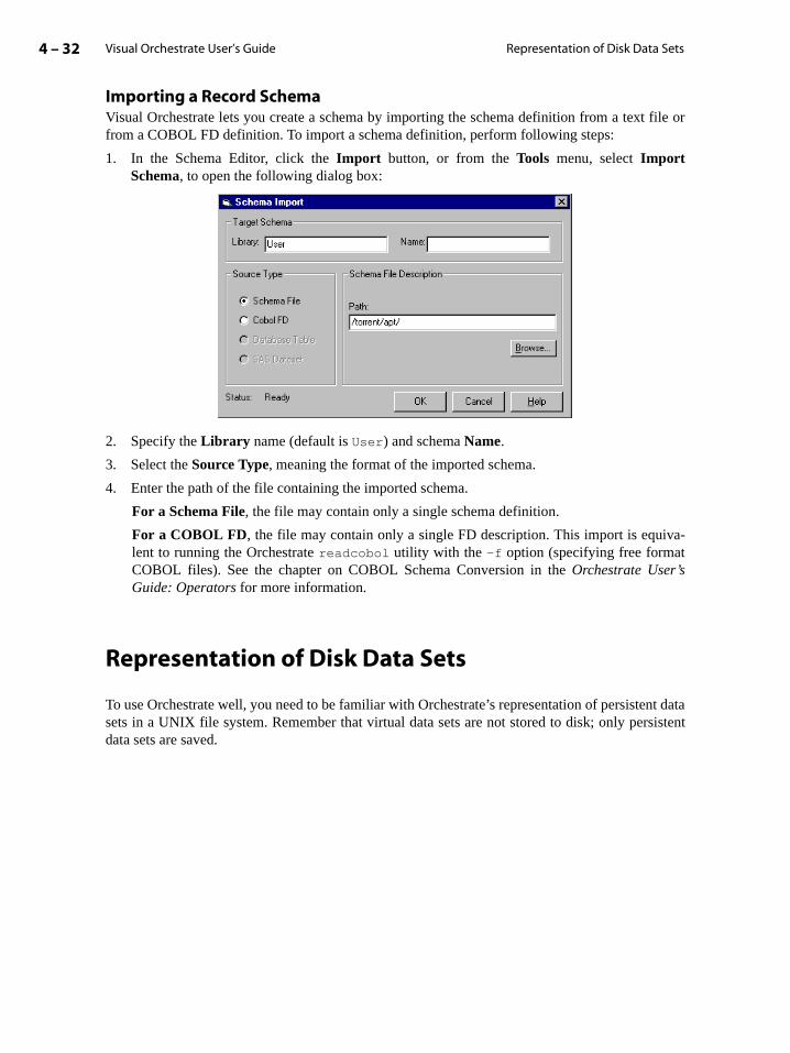
Visual Orchestrate User’s Guide4 – 32 Representation of Disk Data Sets
nt datasistent
Importing a Record Schema Visual Orchestrate lets you create a schema by importing the schema definition from a text file orfrom a COBOL FD definition. To import a schema definition, perform following steps:
1. In the Schema Editor, click the Import button, or from the Tools menu, select ImportSchema, to open the following dialog box:
2. Specify the Library name (default is User) and schema Name.
3. Select the Source Type, meaning the format of the imported schema.
4. Enter the path of the file containing the imported schema.
For a Schema File, the file may contain only a single schema definition.
For a COBOL FD, the file may contain only a single FD description. This import is equiva-lent to running the Orchestrate readcobol utility with the -f option (specifying free formatCOBOL files). See the chapter on COBOL Schema Conversion in the Orchestrate User’sGuide: Operators for more information.
Representation of Disk Data Sets
To use Orchestrate well, you need to be familiar with Orchestrate’s representation of persistesets in a UNIX file system. Remember that virtual data sets are not stored to disk; only perdata sets are saved.
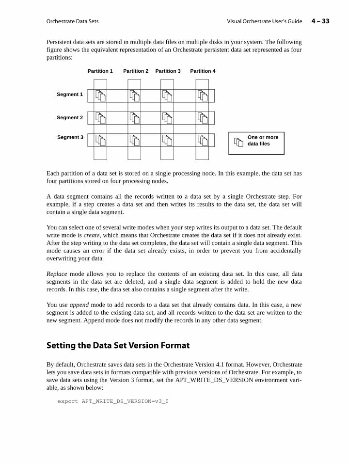
Orchestrate Data Sets 4 – 33Visual Orchestrate User’s Guide
Persistent data sets are stored in multiple data files on multiple disks in your system. The followingfigure shows the equivalent representation of an Orchestrate persistent data set represented as fourpartitions:
Each partition of a data set is stored on a single processing node. In this example, the data set hasfour partitions stored on four processing nodes.
A data segment contains all the records written to a data set by a single Orchestrate step. Forexample, if a step creates a data set and then writes its results to the data set, the data set willcontain a single data segment.
You can select one of several write modes when your step writes its output to a data set. The defaultwrite mode is create, which means that Orchestrate creates the data set if it does not already exist.After the step writing to the data set completes, the data set will contain a single data segment. Thismode causes an error if the data set already exists, in order to prevent you from accidentallyoverwriting your data.
Replace mode allows you to replace the contents of an existing data set. In this case, all datasegments in the data set are deleted, and a single data segment is added to hold the new datarecords. In this case, the data set also contains a single segment after the write.
You use append mode to add records to a data set that already contains data. In this case, a newsegment is added to the existing data set, and all records written to the data set are written to thenew segment. Append mode does not modify the records in any other data segment.
Setting the Data Set Version Format
By default, Orchestrate saves data sets in the Orchestrate Version 4.1 format. However, Orchestratelets you save data sets in formats compatible with previous versions of Orchestrate. For example, tosave data sets using the Version 3 format, set the APT_WRITE_DS_VERSION environment vari-able, as shown below:
export APT_WRITE_DS_VERSION=v3_0
One or moredata files
Partition 1 Partition 2 Partition 3 Partition 4
Segment 1
Segment 2
Segment 3
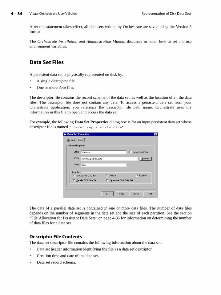
Visual Orchestrate User’s Guide4 – 34 Representation of Disk Data Sets
he datam youres the
se
ta files section
mber
After this statement takes effect, all data sets written by Orchestrate are saved using the Version 3format.
The Orchestrate Installation and Administration Manual discusses in detail how to set and useenvironment variables.
Data Set Files
A persistent data set is physically represented on disk by:
• A single descriptor file
• One or more data files
The descriptor file contains the record schema of the data set, as well as the location of all tfiles. The descriptor file does not contain any data. To access a persistent data set froOrchestrate application, you reference the descriptor file path name. Orchestrate usinformation in this file to open and access the data set.
For example, the following Data Set Properties dialog box is for an input persistent data set whodescriptor file is named /torrent/apt/infile.data:
The data of a parallel data set is contained in one or more data files. The number of dadepends on the number of segments in the data set and the size of each partition. See the“File Allocation for Persistent Data Sets” on page 4-35 for information on determining the nuof data files for a data set.
Descriptor File ContentsThe data set descriptor file contains the following information about the data set:
• Data set header information identifying the file as a data set descriptor.
• Creation time and date of the data set.
• Data set record schema.
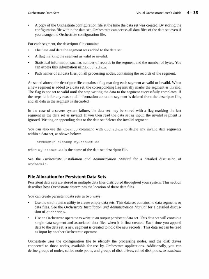
Orchestrate Data Sets 4 – 35Visual Orchestrate User’s Guide
ng theeven if
s. You
ent.
When invalid.tes. Ifor file,
he lastment is
ts
section
nts or
ntain aappendn be read
drivesu can
• A copy of the Orchestrate configuration file at the time the data set was created. By storiconfiguration file within the data set, Orchestrate can access all data files of the data set you change the Orchestrate configuration file.
For each segment, the descriptor file contains:
• The time and date the segment was added to the data set.
• A flag marking the segment as valid or invalid.
• Statistical information such as number of records in the segment and the number of bytecan access this information using orchadmin.
• Path names of all data files, on all processing nodes, containing the records of the segm
As stated above, the descriptor file contains a flag marking each segment as valid or invalid.a new segment is added to a data set, the corresponding flag initially marks the segment asThe flag is not set to valid until the step writing the data to the segment successfully complethe steps fails for any reason, all information about the segment is deleted from the descriptand all data in the segment is discarded.
In the case of a severe system failure, the data set may be stored with a flag marking tsegment in the data set as invalid. If you then read the data set as input, the invalid segignored. Writing or appending data to the data set deletes the invalid segment.
You can also use the cleanup command with orchadmin to delete any invalid data segmenwithin a data set, as shown below:
orchadmin cleanup myDataSet.ds
where myDataSet.ds is the name of the data set descriptor file.
See the Orchestrate Installation and Administration Manual for a detailed discussion oforchadmin.
File Allocation for Persistent Data SetsPersistent data sets are stored in multiple data files distributed throughout your system. This describes how Orchestrate determines the location of these data files.
You can create persistent data sets in two ways:
• Use the orchadmin utility to create empty data sets. This data set contains no data segmedata files. See the Orchestrate Installation and Administration Manual for a detailed discus-sion of orchadmin.
• Use an Orchestrate operator to write to an output persistent data set. This data set will cosingle data segment and associated data files when it is first created. Each time you data to the data set, a new segment is created to hold the new records. This data set caas input by another Orchestrate operator.
Orchestrate uses the configuration file to identify the processing nodes, and the disk connected to those nodes, available for use by Orchestrate applications. Additionally, yodefine groups of nodes, called node pools, and groups of disk drives, called disk pools, to constrain

Visual Orchestrate User’s Guide4 – 36 Representation of Disk Data Sets
ors and
ata set:
lt disk
set:
defaultn of the
e dataol Con-
files onhe sec-con-
disk
tent dataor this
d to two
drives on all
operations to those elements within the pool. See the section “Using Constraints with OperatSteps” on page 10-5 for more information.
Several factors influence the number and location of the data files used to hold a persistent d
• The number of processing nodes in the default node pool
• Any node constraints applied to the operator writing to an output data set
• The number of disk drives connected to each processing node included within the defaupool
• Any disk pool constraints applied to the output data set
Listed below are the rules Orchestrate uses to allocate data files for storing a persistent data
Rule 1. By default, Orchestrate executes an operator on all processing nodes defined in the node pool. When an operator writes to an output data set, Orchestrate creates one partitiodata set on each processing node executing the operator.
Rule 2. If you impose a node constraint on the operator, Orchestrate creates a partition of thset only on those processing nodes executing the operator. See the section “Using Node Postraints” on page 10-6 for information on specifying a node pool constraint.
Rule 3. For each processing node storing a partition of a data set, Orchestrate creates dataall the disk drives included in the default disk pool connected to the processing node. See ttion “Using Resource Constraints” on page 10-7 for information on specifying a disk pool straint.
Rule 4. If you impose a disk pool constraint, Orchestrate creates data files on only thosedrives in the specified disk pool.
For example, suppose your application uses data set create mode to write 16 GB to a persisset. Since the data set did not already exist, it will be created with a single data segment. Fexample, the data set’s descriptor file is named /home/user1/myDataSet.ds.
This example executes on an eight-node system in which each processing node is connectedisk drives. The following figure shows the system for this example:
In this example, all processing nodes are contained in the default node pool, and both diskare contained in the default disk pool. The operator writing to the output data set executesprocessing nodes.
High-speed switch
Ethernet
node0_css
node0
node1_css
node1
node2_css
node2
node3_css
node3
node4_css
node4
node5_css
node5
node6_css
node6
node7_css
node7

Orchestrate Data Sets 4 – 37Visual Orchestrate User’s Guide
n of a
ration
et.
the
Since all eight processing nodes execute the writing operator, Orchestrate creates eight partitionsfor the data set, one on each processing node. Orchestrate further divides each partition among thetwo disks in the default disk pool connected to each node to create 16 data files. Because each nodereceives approximately a 2-GB partition, the total amount of free space in all disks in the defaultpool on each processing node must be at least 2 GB.
If the data set held 64 GB, each of the 16 disks in the system would be required to hold 4 GB. Sincemany operating systems limit file size to 2 GB, each disk would hold two data files of 2 GB each.
Each data segment uses its own data files for storing the records of the segment. If you append datato an existing data set, a new segment descriptor is created, and new data files are created to holdthe records in the new data segment.
In some circumstances, you may need your application to execute its operators on one set ofprocessing nodes and store its data on another. The default operation of Orchestrate is to store apartition of a data set on each node executing the writing operator. When you want to store the datasomewhere else, you insert a copy operator at the end of your step and use node constraints toexecute the copy operator only on the processing nodes on which you want to store your data set.See the chapter “Constraints” for more information on node pools.
File Naming for Persistent Data SetsOrchestrate uses the following naming scheme for the data files that make up each partitioparallel data set:
disk/descriptor.user.host.ssss.pppp.nnnn.pid.time.index.random
where:
• disk: Path for the disk resource storing the data file as defined in the Orchestrate configufile.
• descriptor: Name of the data set descriptor file.
• user: Your user name.
• host: Hostname from which you invoked the Orchestrate application creating the data s
• ssss: 4 digit segment identifier (0000-9999)
• pppp: 4 digit partition identifier (0000-9999)
• nnnn: 4 digit file identifier (0000-9999) within the partition
• pid: Process ID of the Orchestrate application on the host from which you invokedOrchestrate application that creates the data set.
• time: 8-digit hexadecimal time stamp in seconds.
• index: 4-digit number incremented for each file.
• random: 8 hexadecimal digits containing a random number to insure unique file names.
For example, suppose that your configuration file contains the following node definitions:
{node node0 {

Visual Orchestrate User’s Guide4 – 38 Representation of Disk Data Sets
fastname "node0_css" pool "" "node0" "node0_css" resource disk "/orch/s0" {}resource scratchdisk "/scratch" {}
}node node1 {
fastname "node1_css" pool "" "node1" "node1_css" resource disk "/orch/s0" {}resource scratchdisk "/scratch" {}
}}
For this example, your application creates a persistent data set with a descriptor file named /data/mydata.ds. In this case, Orchestrate creates two partitions for the data set: one on each processingnode defined in the configuration file. Because each processing node contains only a single diskspecification, each partition of mydata.ds would be stored in a single file on each processingnode. The data file for partition 0 on the disk /orch/s0 on node0 is named:
/orch/s0/mydata.ds.user1.host1.0000.0000.0000.1fa98.b61345a4.0000.88dc5aef
and the data file for partition 1 on node1 is named:
/orch/s0/mydata.ds.user1.host1.0000.0001.0000.1fa98.b61345a4.0001.8b3cb144
5 – 1Visual Orchestrate User’s Guide
-
handle
e or
ration
5: Orchestrate Operators
Orchestrate operators are the basic functional units of every Orchestrate application. Anoperator takes in data sets, RDBMS tables, or data files, and produces data sets, RDBMStables, or data files. An Orchestrate step consists of one or more Orchestrate operators thatprocess the data, according to the data-flow model for the step.
Orchestrate provides libraries of predefined operators for essential functions, such as import/export and sorting. For descriptions of operator interfaces and other details about individualoperators in the Orchestrate libraries, see the Orchestrate User’s Guide: Operators.
Orchestrate also lets you create your own operators, with either of the following methods:
• Creating an operator from a UNIX command, script, or program, as described in thechapter “Creating UNIX Operators”.
• Creating an operator from a few lines of your C or C++ code, as described in the chapter“Creating Custom Operators”.
In addition, you can use operators that you obtain from third-party developers in yourOrchestrate application.
This chapter describes how to use predefined, user-defined, and third-party-developed operators in Orchestrate applications, through the following sections:
• “Operator Overview” on page 5-1
• “Using Visual Orchestrate with Operators” on page 5-3
• “Operator Interface Schemas” on page 5-6
• “Data Set and Operator Data Type Compatibility” on page 5-17
Operator Overview
In general, an Orchestrate operator takes zero or more data sets as input, performs an operation onall records of the input data sets, and writes its results to zero or more output data sets. Data sets aredescribed in detail in the chapter “Orchestrate Data Sets”.
Some operators limit the number of input or output data sets they handle, while others can any number of data sets (n-input, m-output).
Most Orchestrate steps include one or more of the following kinds of operators:
• A one-output operator is usually the first operator in a step, to import data from a disk filRDBMS and convert it into a data set.
• A one-input, one-output operator takes a single input data set, performs a processing ope

Visual Orchestrate User’s Guide5 – 2 Operator Overview
type
or in
Manydefaultlly.e with
nodesdisk or ait, oree then on
roughoutered in
not be
tep, you thed to
on it, and creates a single output data set.
• A one-input operator is usually used to export a data set to a disk file or an RDBMS. Thisof operator is often the final operator in a step.
The following figure shows these three kinds of operators:
Operator Execution Modes
Orchestrate operators execute in either parallel mode, on multiple processing nodes,sequential mode, on a single processing node.
Every Orchestrate operator has a default execution mode, either parallel or sequential.Orchestrate operators allow you to override the default execution mode. For example, the execution mode of the copy operator is parallel, but you can configure it to run sequentiaSetting the operator execution mode is described in the section “Using Visual OrchestratOperators” on page 5-3.
In some circumstances, you may want to run an operator in parallel but limit the processingthat it uses. The reason might be that the operator requires system resources, such as a large amount of memory, that is not available to all nodes. Orchestrate allows you to limconstrain, an operator to a particular set of nodes to meet your application’s requirements. Ssection “Using Constraints with Operators and Steps” on page 10-5 for more informatiocontrolling the processing nodes used by an operator.
Persistent Data Sets and Steps
Orchestrate steps consist of one or more operators, connected by data sets, as discussed ththe preceding chapters. Creating and using steps to build Orchestrate applications is covdetail in the chapter “Orchestrate Steps”.
As mentioned in the section “Using Data Sets with Operators” on page 4-3, a data set file canboth read from and written to in a single step.
If you want to write to a persistent data set and also use the data set as input in the same sneed to use the Orchestrate copy operator to make a copy of the data set. For example,following data-flow diagram shows the copy operator outputting both a persistent data set save
one-input one-outputoperatorone-output operator one-input operator

Orchestrate Operators 5 – 3Visual Orchestrate User’s Guide
disk and a virtual data set that is input to the next operator in the step. See the Orchestrate User’sGuide: Operators for more information on the copy operator.
Using Visual Orchestrate with Operators
This section describes how to use Visual Orchestrate to configure operators.
1. Open an existing program, or create a new one.
2. To create an operator, do one of the following:
• Select Program -> Add Operator from the menu.
• Click the operator icon in the tool bar.
• With the cursor in a Program Editor window, click the right mouse button and select AddOperator from the popup menu.
• Click the operator name in the Server View and drag it into the Program Editor.
copy operator
Step 1Persistent input data set
Persistent output data set
Virtual data set
Operator
Operator

Visual Orchestrate User’s Guide5 – 4 Using Visual Orchestrate with Operators
The operator icon appears in the Program Editor window, as shown below:
3. Double click the operator icon to open the Operator Properties dialog box. This dialog box isshown below:
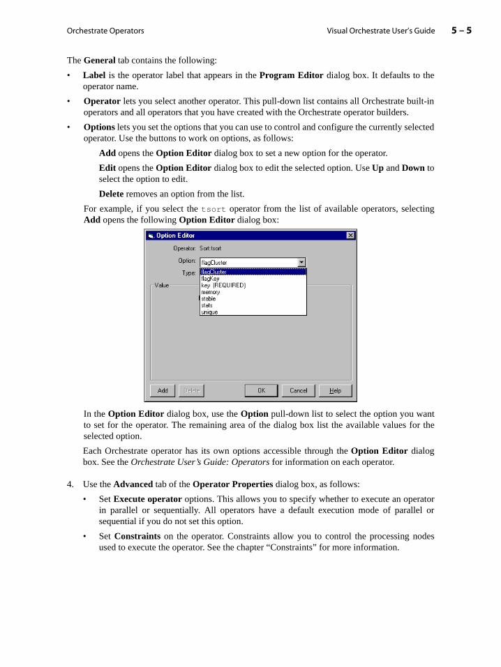
Orchestrate Operators 5 – 5Visual Orchestrate User’s Guide
ilt-in.
lected
ng
tor the
atorl or
des
The General tab contains the following:
• Label is the operator label that appears in the Program Editor dialog box. It defaults to theoperator name.
• Operator lets you select another operator. This pull-down list contains all Orchestrate buoperators and all operators that you have created with the Orchestrate operator builders
• Options lets you set the options that you can use to control and configure the currently seoperator. Use the buttons to work on options, as follows:
Add opens the Option Editor dialog box to set a new option for the operator.
Edit opens the Option Editor dialog box to edit the selected option. Use Up and Down toselect the option to edit.
Delete removes an option from the list.
For example, if you select the tsort operator from the list of available operators, selectiAdd opens the following Option Editor dialog box:
In the Option Editor dialog box, use the Option pull-down list to select the option you wanto set for the operator. The remaining area of the dialog box list the available values fselected option.
Each Orchestrate operator has its own options accessible through the Option Editor dialogbox. See the Orchestrate User’s Guide: Operators for information on each operator.
4. Use the Advanced tab of the Operator Properties dialog box, as follows:
• Set Execute operator options. This allows you to specify whether to execute an operin parallel or sequentially. All operators have a default execution mode of parallesequential if you do not set this option.
• Set Constraints on the operator. Constraints allow you to control the processing noused to execute the operator. See the chapter “Constraints” for more information.

Visual Orchestrate User’s Guide5 – 6 Operator Interface Schemas
in an
he inputroughpstream
sults to
re thest have
escribeperator.
Operator Interface Schemas
Orchestrate schemas are described in the section “Record Schemas” on page 4-2. To be usedOrchestrate application, an operator has an interface schema for each of its input and output datasets. An output interface schema is propagated from an operator to the output data set, to tinterface of the next operator downstream, to that operator’s output interface, and so forth ththe operators in the step. Because an output data set schema would be overridden by the uoperator’s output interface schema, specifying an output data set schema is unnecessary.
The interface schemas of all the Orchestrate built-in operators are described in the OrchestrateUser’s Guide: Operators. Defining an interface schema is part of creating a user-defined operator;as described in the chapter “Creating Custom Operators”.
Example of Input and Output Interface Schema
The following figure shows an operator that takes a single data set as input and writes its rea single output data set.
The figure shows the operator’s input and output interface schemas, which in this case asame. This interface schema specifies that the data set (both the input and the output) mutwo integer fields named field1 and field2 and a floating-point field named field3.
The following sections describe using input and output data sets with operators. They also ddata type conversions between a data set’s record schema and the interface schema of an o
Input data set
Input interface schema
Output interface schema
Output data set
field1:int32; field2:int16; field3:sfloat
field1:int32; field2:int16; field3:sfloat
Operator

Orchestrate Operators 5 – 7Visual Orchestrate User’s Guide
namedet’soperator.
r fields.regate
tor withpute that
Input Data Sets and Operators
The following figure shows an input data set used with an operator:
The operator’s input interface schema requires the input data set to have three fields field1, field2, and field3, with compatible data types. In this example, the input data srecord schema exactly matches the input interface schema and is therefore accepted by the
Input data sets can contain aggregate fields (subrecords and tagged fields), as well as vectoTo be compatible, the operator input interface must contain a corresponding vector or aggfield in its input interface schema.
Operators that Ignore Extra Input FieldsSome operators ignore any extra fields in an input data set, so that you can use the operaany data set that has at least the fields that are compatible with those of the operator’s ininterface schema. The following example shows such an operator, with an input interfacdefines three fields, taking as input a data set that defines five fields:
field1:int32; field2:int16; field3: sfloat
Output data set
Input data set schemafield1:int32; field2:int16; field3:sfloat
field1:int32;field2:int16;field3:sfloat;field4:string;field5:dfloat
field1:int32;field2:int16;field3:sfloat
Output data set schema
field1:int32; field2:int16; field3:sfloat
field1:int32; field2:int16; field3:sfloat
Input data set schema
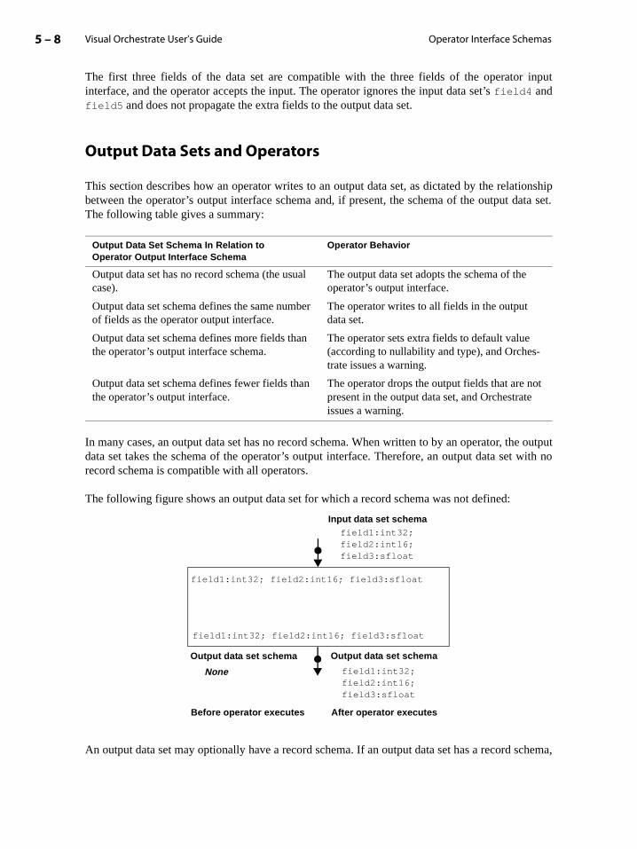
Visual Orchestrate User’s Guide5 – 8 Operator Interface Schemas
tionshipata set.
e output with no
schema,
The first three fields of the data set are compatible with the three fields of the operator inputinterface, and the operator accepts the input. The operator ignores the input data set’s field4 andfield5 and does not propagate the extra fields to the output data set.
Output Data Sets and Operators
This section describes how an operator writes to an output data set, as dictated by the relabetween the operator’s output interface schema and, if present, the schema of the output dThe following table gives a summary:
In many cases, an output data set has no record schema. When written to by an operator, thdata set takes the schema of the operator’s output interface. Therefore, an output data setrecord schema is compatible with all operators.
The following figure shows an output data set for which a record schema was not defined:
An output data set may optionally have a record schema. If an output data set has a record
Output Data Set Schema In Relation to Operator Output Interface Schema
Operator Behavior
Output data set has no record schema (the usual case).
The output data set adopts the schema of the operator’s output interface.
Output data set schema defines the same number of fields as the operator output interface.
The operator writes to all fields in the output data set.
Output data set schema defines more fields than the operator’s output interface schema.
The operator sets extra fields to default value (according to nullability and type), and Orches-trate issues a warning.
Output data set schema defines fewer fields than the operator’s output interface.
The operator drops the output fields that are notpresent in the output data set, and Orchestrate issues a warning.
None
field1:int32; field2:int16; field3:sfloat
Output data set schema
Input data set schemafield1:int32; field2:int16; field3:sfloat
field1:int32; field2:int16; field3:sfloat
field1:int32;field2:int16;field3:sfloat
Output data set schema
Before operator executes After operator executes

Orchestrate Operators 5 – 9Visual Orchestrate User’s Guide
e sames to all
t case, In the
it must be compatible with the output interface schema of the operator. As shown in the second fig-ure in the section “Input Data Sets and Operators” on page 5-7, if the output data set has thnumber of fields and they are compatible with the output interface schema, the operator writethe fields.
An output data set can define fewer fields than the operator’s output interface schema. In thathe operator drops the fields not defined in the output data set, and it issues a warning.example shown in the figure below, the operator drops field4 and field5 from the outputinterface schema:
field1:int32;field2:int16;field3:sfloat;field4:string;field5:dfloat
field1:int32;field2:int16;field3:sfloat
Output data set schema
field1:int32; field2:int16; field3:sfloat
Input data set schema
field1:int32; field2:int16; field3:sfloat
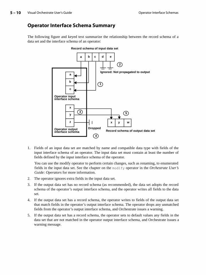
Visual Orchestrate User’s Guide5 – 10 Operator Interface Schemas
e data
ata setatched
s in the issues a
Operator Interface Schema Summary
The following figure and keyed text summarize the relationship between the record schema of adata set and the interface schema of an operator:
1. Fields of an input data set are matched by name and compatible data type with fields of theinput interface schema of an operator. The input data set must contain at least the number offields defined by the input interface schema of the operator.
You can use the modify operator to perform certain changes, such as renaming, to enumeratedfields in the input data set. See the chapter on the modify operator in the Orchestrate User’sGuide: Operators for more information.
2. The operator ignores extra fields in the input data set.
3. If the output data set has no record schema (as recommended), the data set adopts the recordschema of the operator’s output interface schema, and the operator writes all fields to thset.
4. If the output data set has a record schema, the operator writes to fields of the output dthat match fields in the operator’s output interface schema. The operator drops any unmfields from the operator’s output interface schema, and Orchestrate issues a warning.
5. If the output data set has a record schema, the operator sets to default values any fielddata set that are not matched in the operator output interface schema, and Orchestratewarning message.
Ignored: Not propagated to output
2
a b c d e
x y w
5
4
1
3x
y
z
a
b
c
Dropped
Operator input interface schema
Operator output interface schema Record schema of output data set
Record schema of input data set

Orchestrate Operators 5 – 11Visual Orchestrate User’s Guide
Record Transfers and Schema Variables
Some operators take or write an entire record, regardless of its size or the number and types of itsfields. In an operator interface schema, an entire record is represented by a schema variable. A fieldthat is a schema variable has an asterisk (*) in place of a data type; for example, inrec:*. Schemavariables give flexibility and efficiency to operators that input and/or output data on the recordlevel without regard to the record schema.
By default, an operator with a schema variable in its interface schema transfers (copies) an entirerecord from an input data set to an output data set, regardless of the other elements of the input andoutput interface schema. The following figure shows this default behavior for an operator thatincludes a schema variable in its input and output interface schema:
Transfers are used by some operators that modify the input data set and by others that do not. Forexample, the operator lookup modifies the input data set, and the operator peek performs atransfer without modifying the input data set.
Suppose that the operator in the figure above calculates the mean and standard deviation of thethree fields identified in the input interface schema, across the entire input data set. In calculatingthese statistics, the operator does not have to modify the records of the input data set. This operatorreads the records, makes calculations, and transfers each record to the output data set withoutchange.
An operator can combine a schema variable in the output interface schema with additional,enumerated fields, as shown in the following figure:
Output data set
Input data set
field1:int32; field2:int16; field3:sfloat; inRec:*
outRec:*
Entire record transferred from input data set to output data set
Output data set
Input data set
field1:int32; field2:int16; inRec:*
sum:int32; outRec:*

Visual Orchestrate User’s Guide5 – 12 Operator Interface Schemas
In this example, the operator transfers the entire input record to the output data set and adds anadditional field, which holds the sum of field1 and field2.
Determining the Record Schema of a Schema VariableA schema variable refers to an entire input or output record, regardless of any other fields in theinterface schema. This section describes how to determine the record schema associated with aschema variable.
The following figure shows an operator with schema variables in its interface. below the figure arethe record schemas represented by the input and output schema variables:
field1: int32;field2: int16;field3: sfloat;field4: int8
inRec:* ≡ field1:int32; field2:int16; field3:sfloat; field4:int8outRec:* ≡ field1:int32; field2:int16; field3:sfloat; field4:int8
Input data set schema
Output data set
outRec:*
field1:int32; field2:int16; inRec:*
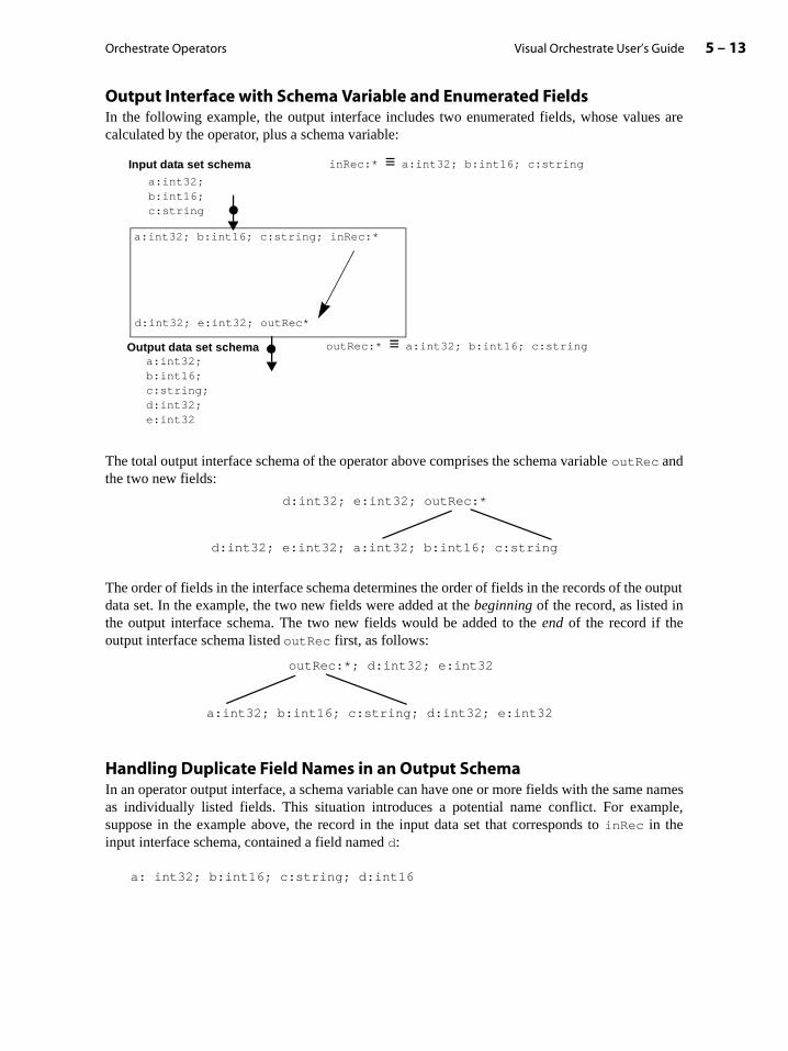
Orchestrate Operators 5 – 13Visual Orchestrate User’s Guide
Output Interface with Schema Variable and Enumerated FieldsIn the following example, the output interface includes two enumerated fields, whose values arecalculated by the operator, plus a schema variable:
The total output interface schema of the operator above comprises the schema variable outRec andthe two new fields:
The order of fields in the interface schema determines the order of fields in the records of the outputdata set. In the example, the two new fields were added at the beginning of the record, as listed inthe output interface schema. The two new fields would be added to the end of the record if theoutput interface schema listed outRec first, as follows:
Handling Duplicate Field Names in an Output SchemaIn an operator output interface, a schema variable can have one or more fields with the same namesas individually listed fields. This situation introduces a potential name conflict. For example,suppose in the example above, the record in the input data set that corresponds to inRec in theinput interface schema, contained a field named d:
a: int32; b:int16; c:string; d:int16
a:int32;b:int16;c:string
Input data set schema inRec:* ≡ a:int32; b:int16; c:string
outRec:* ≡ a:int32; b:int16; c:stringOutput data set schema
a:int32; b:int16; c:string; inRec:*
d:int32; e:int32; outRec*
a:int32;b:int16;c:string;d:int32;e:int32
d:int32; e:int32; outRec:*
d:int32; e:int32; a:int32; b:int16; c:string
outRec:*; d:int32; e:int32
a:int32; b:int16; c:string; d:int32; e:int32
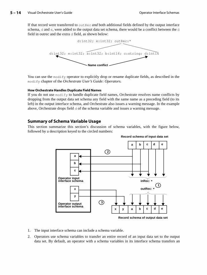
Visual Orchestrate User’s Guide5 – 14 Operator Interface Schemas
elow,
outputfers an
If that record were transferred to outRec and both additional fields defined by the output interfaceschema, d and e, were added to the output data set schema, there would be a conflict between the dfield in outrec and the extra d field, as shown below:
You can use the modify operator to explicitly drop or rename duplicate fields, as described in themodify chapter of the Orchestrate User’s Guide: Operators.
How Orchestrate Handles Duplicate Field NamesIf you do not use modify to handle duplicate field names, Orchestrate resolves name conflicts bydropping from the output data set schema any field with the same name as a preceding field (to itsleft) in the output interface schema, and Orchestrate also issues a warning message. In the exampleabove, Orchestrate drops field d of the schema variable and issues a warning message.
Summary of Schema Variable UsageThis section summarize this section’s discussion of schema variables, with the figure bfollowed by a description keyed to the circled numbers:
1. The input interface schema can include a schema variable.
2. Operators use schema variables to transfer an entire record of an input data set to thedata set. By default, an operator with a schema variables in its interface schema trans
d:int32; e:int32; outRec:*
d:int32; e:int32; a:int32; b:int16; c:string; d:int16
Name conflict
x y a
1x
y
a
b
c
Record schema of output data set
Record schema of input data set
b c d e
a b c d e
outRec: *
inRec: *
2
3
Operator input interface schema
Operator output interface schema

Orchestrate Operators 5 – 15Visual Orchestrate User’s Guide
he enu-me as aleft to
ating third
or, you
any
perator
entire record from an input data set to an output data set, regardless of the other elements ofinput and output interface schemas of the operator.
Operators that do not use schema variables drop unused fields from the records of an input dataset. See the section “Input Data Sets and Operators” on page 5-7 for more information.
3. The output interface schema can include enumerated fields and/or a schema variable. Tmerated fields are added to the output data set. If an enumerated field has the same nafield in the record assigned to the output schema variable, the duplicate field (reading right in the output interface schema) is dropped from the output data set schema.
Flexibly Defined Interface Fields
Many Orchestrate operators (for example, compare) allow flexibility in the fields that they accept.For example, one operator’s dynamic interface might take any number of double-precision flopoint fields as input. Another’s might accept either a single 8-bit integer or a string as input. Aoperator’s dynamic interface could take fields of any data type supported by Orchestrate.
For example, the following figure shows a sample operator, aSort, that has a dynamic interfaceschema:
The input interface accepts two fields and a schema variable. When you invoke this operatpass the names of two fields in the input data set that you want aSort to use as sort keys.
The Orchestrate operator tsort has a more advanced input interface, which lets you specify number of fields as sort keys. The tsort operator interface provides a -key control that takes one ormore field names. With this interface you can, for example, specify age as the sort key. The aSort
operator determines the data type of age from the input data set.
Using Operators with Data Sets That Have Partial Schemas
When an Orchestrate operator processes a data set with a partial schema (defined with theintact
property), the operator cannot add, remove, or modify the data storage in the record. The ocan, however, add result fields to the beginning or end of the record.
name: string;address: string;age: int32
Input data set schema
sortOutDS.ds
outRec:*
_____; _____; inRec:*
aSort

Visual Orchestrate User’s Guide5 – 16 Operator Interface Schemas
a” ontputws an
thecord
For example, the following figure shows an operator adding a field to a data set that uses a partialschema definition:
In this example, the operator adds the extra field, newField, at the beginning of the record. If theoperator output interface listed newField after outRec, the operator would add newField to theend of the output data set schema.
The name of an added field may be the same as a field name in the partial record schema. As withpotential name conflicts involving complete record schemas, you can use the modify operator tohandle the conflict (see the section “Handling Duplicate Field Names in an Output Schempage 5-13). If you do not use modify, Orchestrate drops the duplicate name (considering the ouinterface left to right) from the output data set schema. For example, the following figure shooperator adding a field with the same name, income, as a field in the partial record schema:
In this example, the new income field is added at the beginning of the data set schema, andincome field of the partial record is dropped. Note that dropping a field from a partial reschema eliminates only the field definition, and the contents of the record are not altered.
record {intact} (name:string[20] {position=0};income:int32 {position=44})
Input data set record schema
inRec:*
newField:int32; outRec:*
newField: int32;record {intact} (
name: string[20] {position=0};income: int32 {position=44})
Output data set record schema
record {intact} (name:string[20] {position=0};income:int32 {position=44})
Input data set record schema
inRec:*
newField:int32; outRec:*
income: int32;record {intact} (
name: string[20] {position=0})
Output data set record schema

Orchestrate Operators 5 – 17Visual Orchestrate User’s Guide
fromerted.
te Data
ose of
ws theith the
type
ection
Data Set and Operator Data Type Compatibility
For a data set to be used as input to or output from an operator, its record schema must becompatible with the operator’s interface. For input data set record fields with types that differcorresponding fields of the operator input interface, the types of those fields must be convThe basics of Orchestrate data type conversion are introduced in the chapter “OrchestraTypes”.
For example, the figure below shows an input data set with field data types that differ from ththe operator input interface schema:
The table in the section “Summary of Orchestrate Data Type Conversions” on page 3-9 shodata type conversions that Orchestrate performs by default and those that you can perform wmodify operator.
The following sections contain additional information about default data compatibility and conversions between source and destination data types:
• “Data Type Conversion Errors and Warnings” on page 5-17
• “String and Numeric Data Type Compatibility” on page 5-18
• “Decimal Compatibility” on page 5-19
• “Date, Time, and Timestamp Compatibility” on page 5-20
• “Vector Data Type Compatibility” on page 5-21
• “Aggregate Field Compatibility” on page 5-21
• “Null Compatibility” on page 5-21
Data Type Conversion Errors and Warnings
During data type conversion, Orchestrate detects warning and error conditions. This sdescribes Orchestrate’s actions in warning or error conditions arising from type conversions.
field1:int8;field2:int16;field3:int16
Input data set schema
Output data set
field1:int32; field2:int16; field3:sfloat
field1:int32; field2:int16; field3:sfloat

Visual Orchestrate User’s Guide5 – 18 Data Set and Operator Data Type Compatibility
recurs,estratea step.
n errorto a
tination
ess you
Using modify to Prevent Errors and WarningsTo prevent many of the conditions that lead to warnings and errors caused by type incompatibility,use the modify operator. For example, you can use modify to configure a field to convert a null toa non-null value. Using the modify operator is described in the Orchestrate User’s Guide: Opera-tors.
You can also use modify to suppress warning messages.
Orchestrate Handling of WarningsA warning condition causes Orchestrate to write a message to the warning log. When a field causesa warning condition in consecutive records, the message appears for a maximum of five records.After the fifth warning message, Orchestrate suppresses the message. After a successful dataconversion, Orchestrate’s message counter resets to 0. If the same warning condition thenOrchestrate begins issuing the message again, for up to five more records. However, Orchwill suppress a warning message after it is issued a total of 25 times during the execution of
Conversion Errors and Orchestrate ActionsAn error occurs when Orchestrate cannot perform a data type conversion. For example, aoccurs if you attempt to convert a string field holding nonnumeric data, such as “April”, numeric value.
When a data type conversion error occurs, Orchestrate’s action depends on whether the desfield has been defined as nullable.
Rule 1. If the destination field has been defined as nullable, Orchestrate sets it to null.
Rule 2. If the destination field is not nullable but you have directed modify to convert a null toa value, Orchestrate sets the destination field to the value.
Rule 3. Otherwise, Orchestrate issues an error message and terminates the application. Unlhave disabled warnings, a warning is issued at step-check time.
String and Numeric Data Type Compatibility
You can use the modify operator to perform conversions between type string and numeric types.For information, see the modify chapter in the Orchestrate User’s Guide: Operators.
If you do not explicitly perform a conversion, Orchestrate automatically converts the integer orfloating-point value to its string representation. For example, it converts the integer 34 to thecharacter string "34", and the floating-point 1.23 to "1.23".
For converting string fields to numerics, Orchestrate attempts to interpret the string contents as anumber that matches the data type of the target field. For example, Orchestrate converts the string"34" to the integer 34, and it converts the string "1.23" to the float 1.23. Orchestrate can convert astring-represented floating-point that includes an exponent, represented by "e" followed by thenumbers comprising the exponent. For example, Orchestrate converts "1.23e4" to 12300.0.

Orchestrate Operators 5 – 19Visual Orchestrate User’s Guide
error
Type
s and
s theoceeds
ft of large
ding, it
with a occursounding
e of
oes noted for
Before first performing an automatic type conversion between a string and a numeric type, Orches-trate writes a warning to the error log. Orchestrate also issues a warning for any other type conver-sion that introduces:
• A possible loss in precision, such as a single-precision float converted to a 32-bit integer
• A possible loss in range, such as a 16-bit integer converted to an 8-bit integer
If the conversion between numeric and string data if not possible, a data type conversionoccurs.
For general information on Orchestrate warning and error handling, see the section “DataConversion Errors and Warnings” on page 5-17.
Decimal Compatibility
Orchestrate performs automatic conversions between decimal fields and integer, floating point,and string fields. As part of the conversion, Orchestrate checks for potential range violationloss of precision.
Orchestrate checks for potential range violations before it runs the step that includeconversion. If it detects a potential range violation, it issues a warning message and then prto run the step. A range violation occurs when the magnitude of a source decimal field exceedsthe capacity of the destination data type. The magnitude of a decimal, or number of digits to theleft of the decimal point, is calculated by subtracting the scale of the decimal from the precision.For example, if the decimal has a precision of 15 and a scale of 5, there are ten digits to the lethe decimal point. Converting a decimal of this magnitude can result in a number that is toofor an int16 field, for example.
Orchestrate checks for required rounding before it runs a step. If it detects a need for rounissues a warning message and then proceeds to run the step.
Orchestrate performs the rounding necessary to convert the decimal. A decimal number scale greater than zero represents a real number with a fractional component. Roundingwhen Orchestrate converts a source decimal with a scale greater than zero to an integer. Ralso occurs when Orchestrate converts a source decimal to another decimal with a smaller scale.In both cases, Orchestrate must round the source decimal to fit the destination field.
The default rounding mode used by Orchestrate is called truncate toward zero. In converting adecimal to an integer field, Orchestrate truncates all fractional digits from the decimal. Inconverting a decimal to a decimal, Orchestrate truncates all fractional digits beyond the scalthe destination decimal field. For example, Orchestrate converts the decimal value -63.28 to theinteger value -63.
If the source and destination decimals have the same precision and scale, Orchestrate dperform a default conversion and thus does not check for a potential range violation or a nerounding. You can, however, use the modify operator to perform a decimal_from_decimal
Visual Orchestrate User’s Guide5 – 20 Data Set and Operator Data Type Compatibility
conversion, which may be helpful if the source field allows all zeros and the destination field doesnot (see the modify chapter in the Orchestrate User’s Guide: Operators).
String to Decimal ConversionWhen converting a string to a decimal, Orchestrate interprets the string as a decimal value. To beconverted to a decimal, the string must be in the form:
[+/-]ddd[.ddd]
Orchestrate ignores leading and trailing white space. Orchestrate performs range checking, and ifthe value does not fall into the destination decimal, a requirement failure occurs during setup check.
Decimal to String ConversionYou can also convert a decimal to a string. Orchestrate represents the decimal in the destinationstring in the following format:
[+/-]ddd.[ddd]
Orchestrate does not suppress leading and trailing zeros. If the string is of fixed length, Orchestratepads with spaces as needed.
A fixed-length string must be at least precision+2 bytes long. If a fixed-length string field is notlarge enough to hold the decimal, a range failure occurs.
Date, Time, and Timestamp Compatibility
Orchestrate does not perform any automatic conversions between date, time, or timestamp andother data types. However, you can use the modify operator to perform conversions between thesethree types and most other data types, as described in the modify chapter in the Orchestrate User’sGuide: Operators.
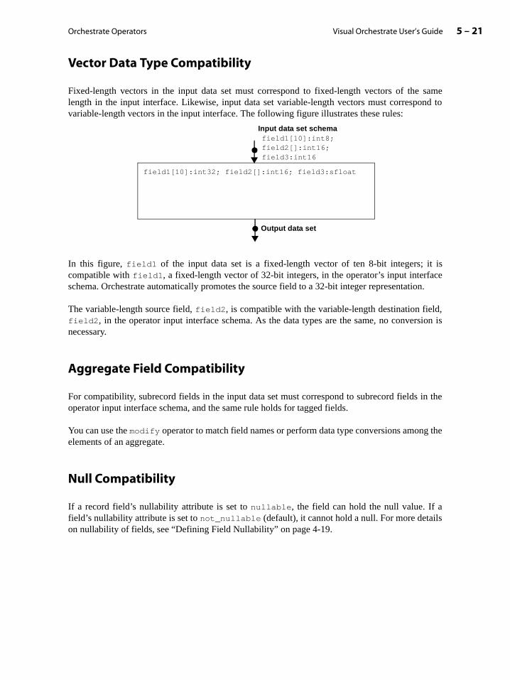
Orchestrate Operators 5 – 21Visual Orchestrate User’s Guide
acen.
d,rsion is
in the
g the
ls
Vector Data Type Compatibility
Fixed-length vectors in the input data set must correspond to fixed-length vectors of the samelength in the input interface. Likewise, input data set variable-length vectors must correspond tovariable-length vectors in the input interface. The following figure illustrates these rules:
In this figure, field1 of the input data set is a fixed-length vector of ten 8-bit integers; it iscompatible with field1, a fixed-length vector of 32-bit integers, in the operator’s input interfschema. Orchestrate automatically promotes the source field to a 32-bit integer representatio
The variable-length source field, field2, is compatible with the variable-length destination fielfield2, in the operator input interface schema. As the data types are the same, no convenecessary.
Aggregate Field Compatibility
For compatibility, subrecord fields in the input data set must correspond to subrecord fieldsoperator input interface schema, and the same rule holds for tagged fields.
You can use the modify operator to match field names or perform data type conversions amonelements of an aggregate.
Null Compatibility
If a record field’s nullability attribute is set to nullable, the field can hold the null value. If afield’s nullability attribute is set to not_nullable (default), it cannot hold a null. For more detaion nullability of fields, see “Defining Field Nullability” on page 4-19.
field1[10]:int8;field2[]:int16;field3:int16
Input data set schema
field1[10]:int32; field2[]:int16; field3:sfloat
Output data set

Visual Orchestrate User’s Guide5 – 22 Data Set and Operator Data Type Compatibility
The following table lists the rules followed for the nullability setting when an operator takes aninput data set or writes to an output data set:
An error occurs only if a source field holds a null value and the destination field is defined asnot_nullable. In this case, Orchestrate issues a fatal error and terminates the application. Youcan use the modify operator to prevent the fatal error; see the chapter on the modify operator inOrchestrate User’s Guide: Operators.
Source Field Destination Field Result
not_nullable not_nullable Source value propagates.
not_nullable nullable Source value propagates; destination value is never null.
nullable not_nullable If source value is not null, source value propagates. If source value is null, a fatal error occurs.
nullable nullable Source value (can be null) propagates.

6 – 1Visual Orchestrate User’s Guide
S-
p
en
ication’s
more
et and
not runm oper- opera-
ore than
ork-ormed
6: Orchestrate Steps
An Orchestrate application consists of at least one step, in which one or more Orchestrateoperators process the application’s data. A step is a data flow, with its input consisting of datafiles, RDBMS data, or persistent data sets. As output, a step produces data files, RDBMdata, or persistent data sets. Steps act as structural units for Orchestrate application development, because each step executes as a discrete unit.
As described in the chapter “Creating Applications with Visual Orchestrate”, you use VisualOrchestrate to create a step. The chapter describes in detail how to implement a multiple-steapplication and also provides information on debugging your application.
Because Orchestrate steps can perform complex processing tasks requiring considerable timto complete, you may want to check the step configuration before you run it. The last sectioof the chapter describes how to check for errors in a step before you run it.
This chapter contains the following sections:
• “Using Steps in Your Application” on page 6-1
• “Working with Steps in Visual Orchestrate” on page 6-4
Using Steps in Your Application
In the data-flow model of your application, a step is bounded by the input and output of persistentdata, which can be flat files or persistent Orchestrate data sets. Because disk I/O consumesresources and time, it is advantageous to use as few steps as possible to perform your applprocessing.
Many applications, however, have conditions that require you to divide processing into two orsteps. The following two conditions require a multiple-step application design:
• The application’s processing includes one operator that outputs a persistent data sanother operator that inputs that data set.
If two operators need to input from and output to the same persistent data set, they canin the same step. For example, suppose in your application you need to use the transforator, which always outputs a persistent data set, and then input that data to the statisticstor. The transform and statistics operators must run in separate steps.
• The application must reiterate an action, so that an operator processes the same data monce.
Looping (reversing the data flow) is not allowed in a step, as described on the section “Wing with Steps in Visual Orchestrate” on page 6-4. Therefore, each iteration must be perfin a separate step.

Visual Orchestrate User’s Guide6 – 2 Using Steps in Your Application
The following section further describes the kinds of data flows that you can use in a step.
The Flow of Data in a Step
To create a step, you connect multiple operators in a data-flow model. The data flow for a step mustbe a directed acyclic graph, which allows multiple inputs and outputs but in which data can flow inonly one direction. However, you cannot use a loop (reverse-direction data flow) in a step.
The following example shows the data-flow model of a valid step that includes multiple outputs(from Operator 1) and multiple inputs (to Operator 4):
The following figure shows a data-flow model of an invalid step, containing a loop:
If you attempt to run a step that includes a loop, Orchestrate terminates execution and issues anerror message. In order to reiterate an operation on a data set, you must create another step.
Step
Operator 1
Operator 2
Operator 3
Operator 4
Operator 1
Operator 2
Step
Loop - not allowed
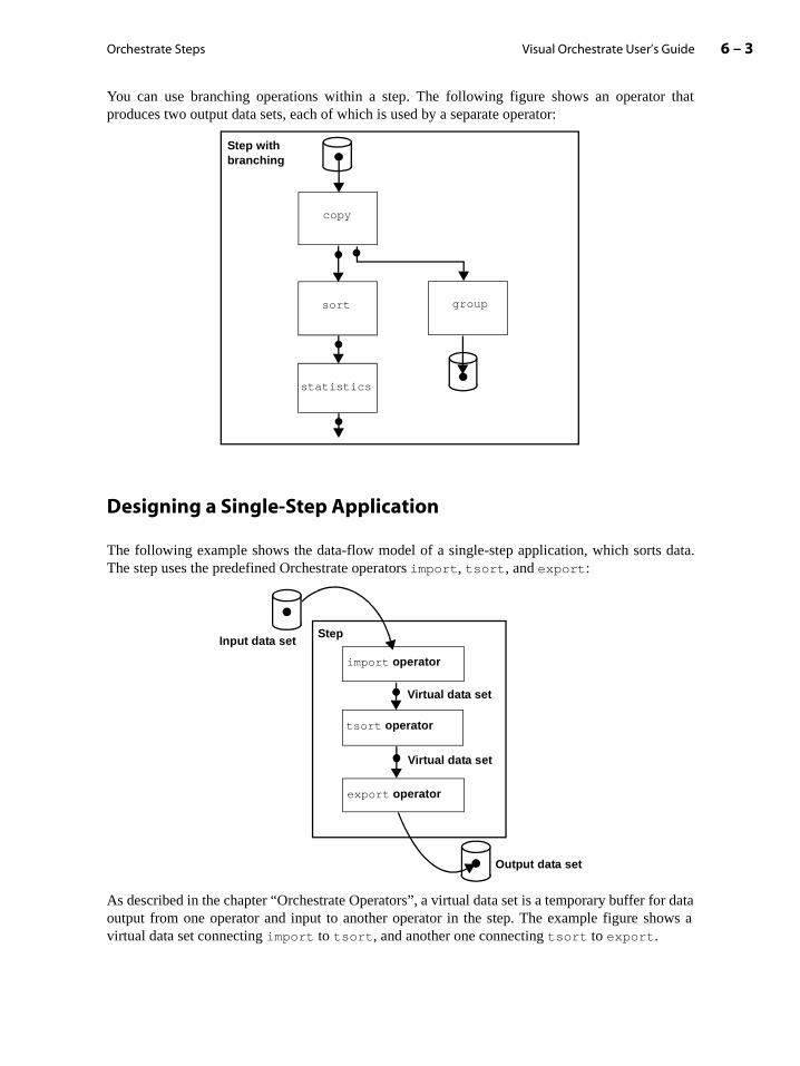
Orchestrate Steps 6 – 3Visual Orchestrate User’s Guide
or dataows a
You can use branching operations within a step. The following figure shows an operator thatproduces two output data sets, each of which is used by a separate operator:
Designing a Single-Step Application
The following example shows the data-flow model of a single-step application, which sorts data.The step uses the predefined Orchestrate operators import, tsort, and export:
As described in the chapter “Orchestrate Operators”, a virtual data set is a temporary buffer foutput from one operator and input to another operator in the step. The example figure shvirtual data set connecting import to tsort, and another one connecting tsort to export.
copy
statistics
groupsort
Step withbranching
Virtual data set
Virtual data set
tsort operator
export operator
Input data set
import operator
Output data set
Step

Visual Orchestrate User’s Guide6 – 4 Working with Steps in Visual Orchestrate
the next
Designing a Multiple-Step Application
In the sample step above, the step takes an input file, performs operations on it, and stores the resultin a file on disk, possibly to be used as input to another step. Storing the output of a step in apersistent data set allows you to create a data set in one step and process the data set in a secondstep. In the following figure, Step 1 performs a preprocessing action, such as sort, on a data set thatStep 2 also requires. By performing the preprocessing in Step 1 and saving the result to a persistentdata set, Step 2 can input the preprocessed data set.
You cannot use a persistent data set both for input and for output within one step. However, asdescribed in the chapter “Orchestrate Data Sets”, you can use the Orchestrate copy operator to savea data set to disk and to output the same data as a virtual data set that can be input to operator in the step.
Working with Steps in Visual Orchestrate
The following sections describe how to use Visual Orchestrate to manipulate steps:
• “Creating Steps” on page 6-5
• “Executing a Step” on page 6-7
• “Setting Server Properties for a Step” on page 6-8
• “Setting Environment Variables” on page 6-10
• “Using Pre and Post Scripts” on page 6-12
copy operator
Operator 2
Step 2
Operator 3
Output data set
Persistent data set
Operator 1
Step 1 Input data set
Input data set

Orchestrate Steps 6 – 5Visual Orchestrate User’s Guide
the
Creating Steps
When you create a new program, Visual Orchestrate automatically creates an initial step for theprogram.
To add a step to a program, perform any one of the following actions:
• Select Program -> Add Step from the menu
• Click the step icon in the tool bar
• Right-click in the Program Editor window background area (outside any step). From popup menu, select Add Step.
The step displays as a box in the Program Editor window, as shown below
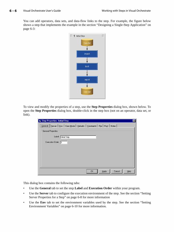
Visual Orchestrate User’s Guide6 – 6 Working with Steps in Visual Orchestrate
on” on
t, or
tting
etting
You can add operators, data sets, and data-flow links to the step. For example, the figure belowshows a step that implements the example in the section “Designing a Single-Step Applicatipage 6-3:
To view and modify the properties of a step, use the Step Properties dialog box, shown below. Toopen the Step Properties dialog box, double-click in the step box (not on an operator, data selink).
This dialog box contains the following tabs:
• Use the General tab to set the step Label and Execution Order within your program.
• Use the Server tab to configure the execution environment of the step. See the section “SeServer Properties for a Step” on page 6-8 for more information
• Use the Env tab to set the environment variables used by the step. See the section “SEnvironment Variables” on page 6-10 for more information.
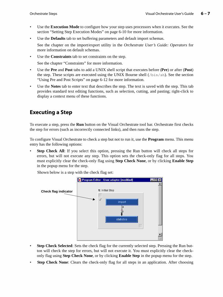
Orchestrate Steps 6 – 7Visual Orchestrate User’s Guide
e the
is tablick to
cks
for. You
but-eck-
ing
• Use the Execution Mode to configure how your step uses processors when it executes. Sesection “Setting Step Execution Modes” on page 6-10 for more information.
• Use the Defaults tab to set buffering parameters and default import schemas.
See the chapter on the import/export utility in the Orchestrate User’s Guide: Operators formore information on default schemas.
• Use the Constraints tab to set constraints on the step.
See the chapter “Constraints” for more information.
• Use the Pre and Post tabs to add a UNIX shell script that executes before (Pre) or after (Post)the step. These scripts are executed using the UNIX Bourne shell (/bin/sh). See the section“Using Pre and Post Scripts” on page 6-12 for more information.
• Use the Notes tab to enter text that describes the step. The text is saved with the step. Thprovides standard text editing functions, such as selection, cutting, and pasting; right-cdisplay a context menu of these functions.
Executing a Step
To execute a step, press the Run button on the Visual Orchestrate tool bar. Orchestrate first chethe step for errors (such as incorrectly connected links), and then runs the step.
To configure Visual Orchestrate to check a step but not to run it, use the Program menu. This menuentry has the following options:
• Step Check All: If you select this option, pressing the Run button will check all stepserrors, but will not execute any step. This option sets the check-only flag for all stepsmust explicitly clear the check-only flag using Step Check None, or by clicking Enable Stepin the popup menu for the step.
Shown below is a step with the check flag set:
• Step Check Selected: Sets the check flag for the currently selected step. Pressing the Runton will check the step for errors, but will not execute it. You must explicitly clear the chonly flag using Step Check None, or by clicking Enable Step in the popup menu for the step.
• Step Check None: Clears the check-only flag for all steps in an application. After choos
Check flag indicator

Visual Orchestrate User’s Guide6 – 8 Working with Steps in Visual Orchestrate
this menu command, pressing the Run button will both check and execute all steps in the appli-cation.
Note: Running an application that displays a great deal of text (more than a few thousand lines) inVisual Orchestrate can negatively affect its performance. When you run a display-intensive appli-cation in Visual Orchestrate, redirect its output from the screen to a file, which you can examineoutside Orchestrate (in a text editor, for example) after the run.
Setting Server Properties for a Step
An Orchestrate program consists of one or more Orchestrate steps. When you create an Orchestrateprogram, you use the Program Properties dialog box to set the global properties on the program.However, you can override many of these properties on individual steps using the Server tab of theStep Properties dialog box, shown below:
Note: Any properties left unchanged in the Step Properties dialog box default to the settings in theProgram Properties dialog box.
You can optionally set any one of the following server properties:
Configuration: Select the Orchestrate configuration used to execute the step. The configurationdefines the processing nodes and disk drives available for use by your program.
The Orchestrate server administrator is required to set up at least one default configurationbefore you can create an Orchestrate step or program. If no configuration is available, seethe Orchestrate server administrator
You may have several different configurations available. For example, one configurationmay be for testing and another for deployment.

Orchestrate Steps 6 – 9Visual Orchestrate User’s Guide
ual to
ual to
vail-ble tom loadusers.
plica-
y seting
e. Forrocess-
Execution Options: Click Check Only to validate the step but not run it, and Execute to executethe step. Click Disabled to cause Visual Orchestrate to skip this step (that is, not to execute the stepas part of the application).
If you change execution options with the menu (such as with Program->Step Check All) or withthe step popup menu (such as with Disable Step), the Execution Options setting on the ServerProperties tab will reflect the setting the next time you open the Step Properties dialog box.
Show Scores causes Visual Orchestrate to display extensive diagnostic information about the stepas it executes.
Shows Schemas causes Visual Orchestrate to print the record schema of all data sets and the inter-face schema of all operators.
Shows Environment causes Visual Orchestrate to display the applicable environment variablesduring the program run.
Max Outstanding KB: Sets the amount of memory, in bytes, reserved for Orchestrate on everynode to communicate over the network. The default value is 2 MB (2048 bytes).
Note: If you are working on a stand-alone workstation or stand-alone SMP, leave Max Outstand-ing KB at its default value.
If your system uses a network to connect multiple processing nodes, such as an IBM switch in anMPP or an Ethernet connection in a network cluster, set Max Outstanding KB as follows:
• If you are using the IBM HPS switch (also referred to as TB2), set a value less than or eq(thewall * 1024)/2.
• If you are using the IBM SP switch (also referred to as TB3), set a value less than or eqMIN(spoolsize, rpoolsize).
• For workstations connected by a network, set a value less than or equal to (thewall * 1024)/2.
Contact your system administrator for the correct setting for Max Outstanding KB. The fol-lowing are some guidelines for determining the setting for your system.
Setting Max Outstanding KB to its maximum value means that Orchestrate reserves all aable memory for communicating over the network, and that no other application will be acommunicate. Set this environment variable based on your understanding of the systerequired by Orchestrate and by all other applications running on the system by all other
For example, if you are using DB2 and Orchestrate together, you could set Max OutstandingKB to reserve 8 MB for Orchestrate. If you are testing Orchestrate by running small aptions, you could set Max Outstanding KB to reserve only 4 MB.
If you run multiple Orchestrate applications concurrently, set Max Outstanding KB to a frac-tion of the value that you would use for a single application. For example, if you normallMax Outstanding KB to 8 MB for a single Orchestrate application, set it to 4 if you are goto run two concurrent Orchestrate applications.
If you use SMP nodes in your system, you must set Max Outstanding KB to the value deter-mined above, divided by the number of Orchestrate nodes defined for the SMP nodexample, if you configure Orchestrate to recognize a single SMP node as two separate p
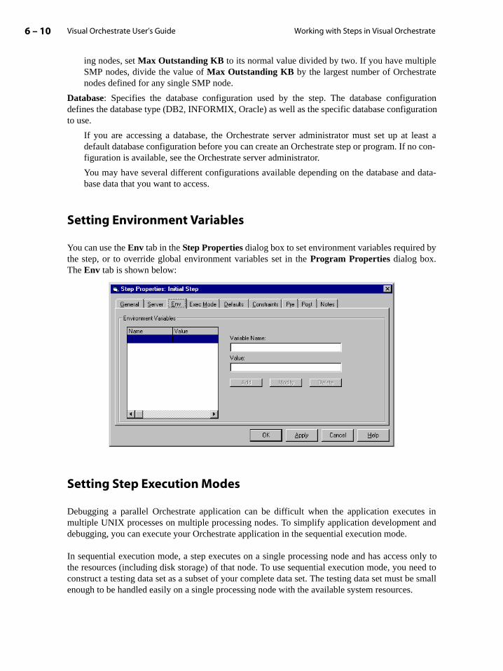
Visual Orchestrate User’s Guide6 – 10 Working with Steps in Visual Orchestrate
ing nodes, set Max Outstanding KB to its normal value divided by two. If you have multipleSMP nodes, divide the value of Max Outstanding KB by the largest number of Orchestratenodes defined for any single SMP node.
Database: Specifies the database configuration used by the step. The database configurationdefines the database type (DB2, INFORMIX, Oracle) as well as the specific database configurationto use.
If you are accessing a database, the Orchestrate server administrator must set up at least adefault database configuration before you can create an Orchestrate step or program. If no con-figuration is available, see the Orchestrate server administrator.
You may have several different configurations available depending on the database and data-base data that you want to access.
Setting Environment Variables
You can use the Env tab in the Step Properties dialog box to set environment variables required bythe step, or to override global environment variables set in the Program Properties dialog box.The Env tab is shown below:
Setting Step Execution Modes
Debugging a parallel Orchestrate application can be difficult when the application executes inmultiple UNIX processes on multiple processing nodes. To simplify application development anddebugging, you can execute your Orchestrate application in the sequential execution mode.
In sequential execution mode, a step executes on a single processing node and has access only tothe resources (including disk storage) of that node. To use sequential execution mode, you need toconstruct a testing data set as a subset of your complete data set. The testing data set must be smallenough to be handled easily on a single processing node with the available system resources.
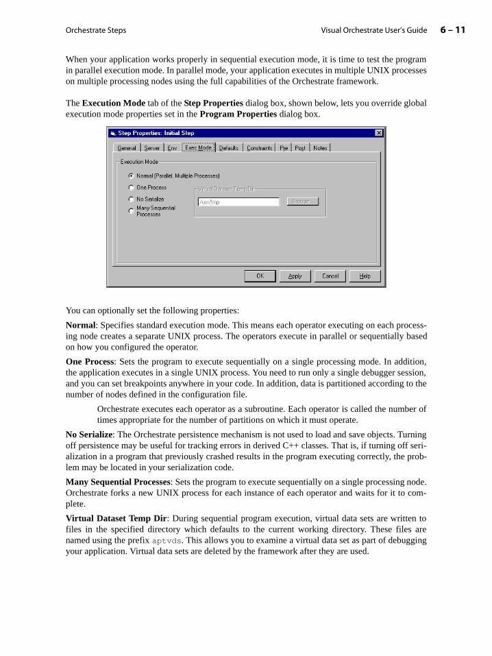
Orchestrate Steps 6 – 11Visual Orchestrate User’s Guide
When your application works properly in sequential execution mode, it is time to test the programin parallel execution mode. In parallel mode, your application executes in multiple UNIX processeson multiple processing nodes using the full capabilities of the Orchestrate framework.
The Execution Mode tab of the Step Properties dialog box, shown below, lets you override globalexecution mode properties set in the Program Properties dialog box.
You can optionally set the following properties:
Normal: Specifies standard execution mode. This means each operator executing on each process-ing node creates a separate UNIX process. The operators execute in parallel or sequentially basedon how you configured the operator.
One Process: Sets the program to execute sequentially on a single processing mode. In addition,the application executes in a single UNIX process. You need to run only a single debugger session,and you can set breakpoints anywhere in your code. In addition, data is partitioned according to thenumber of nodes defined in the configuration file.
Orchestrate executes each operator as a subroutine. Each operator is called the number oftimes appropriate for the number of partitions on which it must operate.
No Serialize: The Orchestrate persistence mechanism is not used to load and save objects. Turningoff persistence may be useful for tracking errors in derived C++ classes. That is, if turning off seri-alization in a program that previously crashed results in the program executing correctly, the prob-lem may be located in your serialization code.
Many Sequential Processes: Sets the program to execute sequentially on a single processing node.Orchestrate forks a new UNIX process for each instance of each operator and waits for it to com-plete.
Virtual Dataset Temp Dir: During sequential program execution, virtual data sets are written tofiles in the specified directory which defaults to the current working directory. These files arenamed using the prefix aptvds. This allows you to examine a virtual data set as part of debuggingyour application. Virtual data sets are deleted by the framework after they are used.
Visual Orchestrate User’s Guide6 – 12 Working with Steps in Visual Orchestrate
assing
ither
se anyKorn
ll
estrate.
tions inides a
Using Pre and Post Scripts
This section describes how to create and use pre and post scripts and server variables, to modify theexecution of your steps. This section includes a detailed example, in the section “Example: Pa Value to an Operator from the Pre Shell Script” on page 6-13.
Creating Pre and Post ScriptsEach Orchestrate step allows you to create and associate two scripts with the step: a Pre and a Postshell script. You can use these scripts to perform such operations as:
• Opening and closing UNIX pipes for use by the import/export operators
• Calculating run-time values passed to Orchestrate operators
• Performing any other pre or post processing actions required by the step
The order of execution of a step and its associated shell scripts:
1. Execute the Pre shell script, if any.
2. Execute the step.
3. Execute the Post shell script, if any.
Note that the Pre and Post shell scripts are independent of each other; that is, you can create ea Pre or a Post shell script, or both.
By default, Orchestrate uses the Bourne shell to execute the shell script. However, you can ushell to execute the script. For example, the first line of the following script specifies the shell:
#!/bin/ksh# script goes here
Each step in an application, as well as each Pre and Post shell script, executes in its own sheenvironment. Any modifications to the UNIX shell environment made by the Pre shell script arenot passed to the shell environment of the step or to that of the Post shell script. Therefore, youcannot use UNIX environment variables to pass information. Instead, you can use Orchserver variables, which exist only during execution of the application in which you create them
Using Orchestrate Server VariablesOrchestrate provides a function that you can use to store on the server the result of calculayour Pre shell script. In your step, operators can reference that value. Orchestrate also provfunction that you can use to access the variable in a Post shell script.
To write a value to the server, use the function:
set_orchserver_variable var_name var_value
Orchestrate Steps 6 – 13Visual Orchestrate User’s Guide
ion of the end
tring.
thee of in the
by theter this
where:
• var_name is a variable name. The server stores the variable and its value for the duratyour Orchestrate program, so that other steps in the program can access the variable. Atof the program run, Orchestrate deletes the variable.
• var_value is the variable’s value and can be an integer (signed or unsigned), float, or sAll values are stored on the server as strings.
To get a value from the server, use the function:
value = get_orchserver_variable var_name
where:
• value is the variable value represented as a string
• var_name is the name of the server variable
get_orchserver_variable returns an exit code of 0 if it succeeds and 1 if it fails. If var_nameis not stored in the server, the call succeeds but returns the empty string.
The following two sections describe examples of using pre scripts and server variables.
Example: Passing a Value to an Operator from the Pre Shell ScriptA common use of the Pre shell script is to calculate the value of an argument for an operator instep. For example, the Orchestrate sample operator takes an argument specifying the percentagan input data set written to each output data set. The percentage is a floating-point valuerange of 0.0, corresponding to 0.0%, to 100.0, corresponding to 100.0%.
Shown below is a shell script that you can use to calculate the percent sample size requiredsample operator to copy 1600 records from the input data ‘set to the output data set. You enscript in the Pre tab area of the Step Properties dialog box:
#!/bin/kshnumSampled=1600 # Line 1numRecs=‘dsrecords inDS.ds | cut -f1 -d' '‘ # Line 2percent=‘echo "10 k $numSampled $numRecs / 100 * p q" | dc‘# Line 3set_orchserver_variable sample_percent ‘echo $percent‘ # Line 4
Line 1. In this example, you want the output data set to contain 1600 records.
Line 2. Use the dsrecords utility to obtain the number of records in the input data set. The returnvalue of dsrecords has the form # records where # is the number of records. This statementreturns the record count and strips off the word record from the value.
Line 3. Calculate a floating point value for the sample percentage from the 1600 records requiredby the sample and the number of records in the data set. This example uses the UNIX dc commandto calculate the percentage. In this command, the term 10 k specifies that the result has 10 digits tothe left of the decimal point. See the man page on dc for more information.
Line 4. Use set_orchserver_variable to write the variable sample_percent to the server.
You can now reference sample_percent in your step, to set the sampling percentage for thesample operator. To reference the sample_percent , double-click the operator to display its

Visual Orchestrate User’s Guide6 – 14 Working with Steps in Visual Orchestrate
Operator Properties dialog box. On the General tab, select Add to add a option or Edit to edit anexisting one. The Options Editor dialog box for the sample operator appears. Click the VariableReference button, marked with a blue V, to select it. In the text field to the left of the VariableReference button, type the variable name, as shown in the following figure:
Each time you run the step, the Pre shell script calculates the required percentage to generate 1600records in the output data set and passes this sampling percentage to the operator.
Variable Reference button

7 – 1Visual Orchestrate User’s Guide
e
7: The Performance Monitor
The Orchestrate performance monitor (also called orchview) produces a graphical, 3-D rep-resentation of an Orchestrate step as it executes. The monitor allows you to track the execu-tion of an Orchestrate step and display statistical information about Orchestrate operatorsduring and after step execution.
This chapter describes the performance monitor, including the monitor’s graphical userinterface. This chapter also describes how to configure your system to use the performancmonitor and how to run the performance monitor.
This chapter contains the following sections:
• “The Performance Monitor Window” on page 7-1
• “Controlling the Performance Monitor Display” on page 7-5
Note: Your system must have X Windows support in order to run the Orchestrate performancemonitor.
The Performance Monitor Window
The performance monitor shows the execution of a step in a 3-D format that allows you to view theoperators and the data flow among the operators that make up the step. You can use the monitor todisplay a step as it executes, or you can record the step and play it back later.
The performance monitor allows you to zoom the display, and rotate the display horizontally andvertically, to examine individual operators or operator connections. You can set a number ofoptions that control how the performance monitor displays your program execution. For example,you can set the frequency at which the entire display is updated. You can also customize the displaystyle for data flows, and the volume or rate cutoff at which the performance monitor shows achange in the data flow.
The performance monitor lets you display statistical information about the operators and the datasets in your program. For example, you can display a snapshot of the current record read and writerates. The performance monitor also has a feature that lets you create a spreadsheet from yourprogram statistics.

Visual Orchestrate User’s Guide7 – 2 The Performance Monitor Window
Shown below is the performance monitor window with a run-time display of a sample application:
Message panel
Control panel

The Performance Monitor 7 – 3Visual Orchestrate User’s Guide
How the Performance Monitor Represents Your Program Steps
The symbols the performance monitor uses to represent operators and data sets are similar to thoseused in data-flow diagrams, as shown below:
As shown in the figure above, the performance monitor displays operators as square grids. Eachused cell in an operator grid represents an instance of the operator on an Orchestrate processingnode. The performance monitor also displays persistent data sets as square grids. Each used cell inthe grid represents an Orchestrate processing node.
An operator grid may also contain cells that are never used, as explained below.
How the Performance Monitor Determines Grid DimensionsAll operator and persistent data contain a square number of cells (4, 9, 16, 25, and so forth),arranged as a square. All the operator and persistent data set grids in a step have the same numberof cells: the largest number of Orchestrate processing nodes used by the step, rounded up to thenearest square number.
For example, if the largest number of processing nodes used by the step is 16, then all operator anddata-set grids have 16 cells (4 rows by 4 columns). In another example, if the largest number ofprocessing nodes used is 22, the number of cells is rounded up to the nearest square number, 25,and every grid in the step has 5x5 cells.
Note: Any cells in a grid that do not represent processing nodes, which the performance monitorhas added to make the grid a square, are never used and therefore never show activity. Do not con-fuse these never-used cells with temporarily inactive cells, which represent Orchestrate nodes butshow no activity in the current display.
The cells in grids for operators and persistent data sets are identified by row-column coordinates,with each row and column indexed 0 through n-1.
In performance monitor In data-flow diagram
Virtual data set
Persistent data set
OpNameOperator
Data flow

Visual Orchestrate User’s Guide7 – 4 The Performance Monitor Window
ed line.ssingtion to ae thee thisesents
-ver isconfigu-
work
from
es for
hold
in
How the Performance Monitor Represents Data FlowsFlows of data (including virtual data sets), among operators and data sets in the step, arerepresented by solid or dashed lines (arcs). The performance monitor treats any data connectionwith no flow of data within a sampling interval as currently inactive, and by default does notdisplay it. You set the sampling interval when you configure the performance monitor (see thesection “Configuring the Performance Monitor” on page 7-4).
During the step’s processing, the performance monitor first represents a data flow as a dashAfter a minimum number of records (by default, 100,000) have been written to one procenode in the virtual data set, the performance monitor changes the virtual data set representasolid line. As explained on the section “Data Set Display Control” on page 7-7, you can usOptions dialog box to enable or suppress the display of inactive data flows. You can also usdialog box to change the minimum number of records at which the performance monitor reprthe flow with a solid line.
Configuring the Performance Monitor
To configure the performance monitor for an entire application, you use the Program Propertiesdialog box, as described below:
1. Choose Program -> Properties to open the Program Properties dialog box.
2. From the Orchview tab, select the Debug Options button. This opens the Step Debug dialogbox.
3. Set the parameters that enable the performance monitor, as follows:
Enable: Click to enable the performance monitor.
Host running Orchview performance monitor: The name of the UNIX processing node running the performance monitor. On MPP systems, this is the node from which the serstarted. On other systems, this is the name of the node as it appears in the Orchestrate ration file, using the node parameter.
X Windows DISPLAY on which Orchview window appears: The name of the machine onwhich the performance monitor output window is displayed. This entry is usually the netname of your PC.
TCP port by which Orchview receives performance data: The logical port number used tocommunicate information from your application to the performance monitor.
The port number must be different from all other performance monitor processes, andthat of other applications that allocate specific port numbers.
Many standard applications port numbers are in the 0-1000 range. Recommended valuthe port number are between 10,000 and 60,000.
Temporary Score File: The name and path of the file used by the performance monitor to data. The performance monitor creates this file if it does not already exist.
Display update interval (seconds): The sampling interval for the performance monitor one-second increments.
The Performance Monitor 7 – 5Visual Orchestrate User’s Guide
the
perfor-
pera-
mplexstep.
Increasing the number reduces the network bandwidth used by the monitor. Decreasing thenumber creates a finer granularity for viewing the step.
Shown below are example settings for these environment variables:
Enable: CheckedHost running Orchview performance monitor: node0 X Windows DISPLAY on which Orchview window appears: myPC:0TCP port by which Orchview receives performance data: 22222Temporary Score File: /home/user1/working_dir/myscorefileDisplay update interval (seconds): 10
Controlling the Performance Monitor Display
This section describes how you can control the display of the performance monitor. Included in thissection is information on:
• “General Display Control” on page 7-5
• “Operator Display Control” on page 7-6
• “Data Set Display Control” on page 7-7
• “Generating a Results Spreadsheet” on page 7-8
General Display Control
The performance monitor contains the following general controls:
• In the menu bar, the Options selection includes several display options, such as settingbackground color of the display window to black or white.
• In the menu bar, the Help selection accesses online help.
• Below the graphical display area, the message panel displays output messages from themance monitor.
• The control panel lets you:
• Automatically pan and zoom the display with the Auto View button.
• Zoom in and out on the display.
• Rotate the step both horizontally and vertically, so you can focus in on a particular otor or connection.
• Change the width of the operator grids. Reducing the size of the grids can make a costep easier to view, and it gives you the option of displaying only the data flow of the

Visual Orchestrate User’s Guide7 – 6 Controlling the Performance Monitor Display
id, yousystem,strict ane cellsith no
on a
ouseant tor of the
n. Toay the
eratorshown
mati-
Operator Display Control
Not all operators execute on all nodes. By observing the data connections to an operator’s grcan determine the number of nodes used to execute it. For example, if you have a 16-node each grid contains 16 cells. However, constraints applied to an operator or to the step can reoperator to executing on a subset of the 16 Orchestrate processing nodes. Only thcorresponding to nodes actually executing the operator have a data connection. Cells wconnection correspond to nodes not used by the operator.
The performance monitor provides the following controls for operator display:
• To move an operator in the window, you use the middle mouse button (or both buttonstwo-button mouse) to click and drag the operator grid in the window.
• To display a window with a snapshot of the statistics about the operator, click the right mbutton on the operator-grid cell that represents the operator instance on which you wobtain statistics. The statistics display includes the operator number and instance numbeoperator cell on which you clicked, as shown below:
The statistics window remains open as long as you hold down the right mouse buttorefresh the statistics display, release the mouse button and then click again to displupdated statistics.
• To display statistics about an operator for which you know the operator number and opinstance number, you can also use the menu to display the operator statistics window above. Choose the Data -> Operator Stats menu selection to open the Specify Operator dia-log box. Enter the operator number into the Specify Operator Number field, and enter theinstance number into the Specify Instance Number field. Then, click the stats... button toopen the statistics window for the operator.
When opened via the menu, the window remains open until you dismiss it, and it is autocally updated every 5 seconds.
Instance number
Operator number

The Performance Monitor 7 – 7Visual Orchestrate User’s Guide
ine theach data-rator to
o nodeso nodes
tion
on the downen con-
shown
dis-of the
win-
ords
pro-
Data Set Display Control
The performance monitor displays virtual data sets as dashed or solid lines, and it displayspersistent data sets as grids. The performance monitor lets you control some aspects of the displayof data sets, and to display statistical information about your data.
Not all persistent data sets are transferred using all processing nodes. From the performancemonitor window, you can see the data connections to a data set’s grid and therefore determnumber of nodes used to store the a data set. For example, if you have a 16-node system, eset grid contains 16 cells, but constraints applied to an operator or to the step restrict an opetransferring the data set on fewer than 16 nodes. Only the data-set grid cells corresponding tactually used for the data set have a data connection. Cells with no connection correspond tthat are not used to transfer the data set.
The performance monitor provides the following options for controlling the display of informaabout a data set:
• To display a snapshot of statistics about a data set, control-click the right mouse button data flow (solid or dashed line). The statistics window remains open as long as you holdthe right mouse button. To refresh the statistics display, release the mouse button and thtrol-click again to display the updated statistics.
The window includes the data-set number and the reading and writing operators, as below:
At the bottom of the window is the information on Arc(N,M), where N is the instance numberof the writing operator and M is the instance number of the reading operator. This window plays information about the partition of the data set connecting the output of instance 0 writing operator to the input of instance 0 of the reading operator.
You can determine the data-set number from this window in order to open the statisticsdow for the operator, described next.
• To display statistical information about a data set and a specific arc in it, choose the Data ->DataSet Stats menu selection. The statistics displayed include the time running, total recpassed, and data-flow rate. The performance monitor updates this window continuously.
• To show the volume of records processed, select Options from the menu to open the Optionsdialog box. In that dialog box, check the selection DS Spectrum Coloring Marker (No. ofRecords). By default, the data-flow line color is determined by the node number of the
Data-set number Writing operator Reading operator
Data-set arc information
Visual Orchestrate User’s Guide7 – 8 Controlling the Performance Monitor Display
eance
t the
-, andption
lid line,
aling
atherst youl, so
at then-
pec-
cessing node writing the data, and the color remains constant throughout processing. Settingthe DS Spectrum Coloring Marker option causes the performance monitor to indicate recordvolume by cycling through the color palette, from orange to violet, changing color when yourspecified number of records has been processed.
• To show the rate of data flow, you can use either of two selections in the Options dialog box:
• DS Spectrum Coloring Marker (Records per Second). Check this option, and enter thnumber of records per second at which you want the color to change. The performmonitor cycles through the color palette (from orange to violet), changing color anumber of records you specify.
• DS Binary Rate Coloring (Records per Second). Using his option causes the performance monitor to display in red the data flows that transfer data below the cutoff rateto display in green the data flow arcs with a rate at or above the cutoff. Check the oand set the cutoff rate in the Records per Second field, and then press Enter.
• To set the number of records processed after which a virtual data set is displayed as a socheck the Options dialog box selection Set DS Solid Line Marker (No. of Records). Thedefault number of records is 100,000.
• To cause the performance monitor to display inactive data connections, use the Options dialogbox selection Show Data Set By Blockage (Solid Line). The performance monitor treats data connection as inactive if no records have been transferred over it during one sampperiod (approximately five seconds).
Generating a Results Spreadsheet
The performance monitor lets you save to a file, in a spreadsheet layout, the information it gon record flow in your data set. The information is saved as tab-delimited ASCII text, so thacan open the file in any ASCII text editor. The format is also compatible with Microsoft Exceyou can use Excel to view your results spreadsheet.
Use the following procedure save your record-flow data to a spreadsheet:
1. In the performance monitor, choose the File -> Save Spread Sheet menu command to open adialog box prompting you for the name of the file.
2. Enter the name of the file.
3. Click the Save Spread Sheet button to save the current data flow information to the file.
This action saves the number of records transferred by every data-flow arc in the steptime you click the Save Spread Sheet button. Clicking on the button again overwrites the cotents of the file with new information.
4. View the file using either an ASCII text editor or in Microsoft Excel.
When you read the file into Excel, Excel opens a text import dialog box allowing you to sify the layout of the file. Use the default value of Delimited text to read the file, then click onthe Finish button.

The Performance Monitor 7 – 9Visual Orchestrate User’s Guide
7 for
The following is an example of the contents of the saved spreadsheet:
Orchestrate Performance Spreadsheet, Copyright (C) 1995 - 2000Torrent Systems, Inc. All Rights Reserved.
Sequence Number: 3Spreadsheet Version: 1Current Date 1997 10 28Current Time 12:35:50Unique Orchestrate Step ID: 60346-878059706Step Start Date 1997 10 28Step Start Time 12:28:26
Data Section:
data saved: detailed data set flow volumes.begin data:
End DataEnd Data SectionSequence Number: 3
In the spreadsheet, the row labels (such as 0,0) specify the partition numbers of the reading andwriting operators for each data-flow arc, in the form.
(writing_partition, reading_partition)
The column labels identify the data sets. To determine the data set that corresponds to the label fora column (such as DS0), control-click the right mouse button on the data flow arc in theperformance monitor display. See the section “Data Set Display Control” on page 7-information about data set arcs.
DS0 DS1 DS2 DS3 DS4 DS5 DS6
(0,0) 673 673 1346 1346 1346 337 337
(0,1) 673 673 0 0 0 337 337
(0,2) 673 673 0 0 0 336 336
(0,3) 672 672 0 0 0 336 336
(1,0) 0 0 0 0 0 337 337
(1,1) 0 0 1346 1346 1346 337 337
(1,2) 0 0 0 0 0 336 336
(1,3) 0 0 0 0 0 336 336
(2,0) 0 0 0 0 0 337 337
(2,1) 0 0 0 0 0 337 337
(2,2) 0 0 1346 1346 1346 336 336
(2,3) 0 0 0 0 0 336 336

Visual Orchestrate User’s Guide7 – 10 Controlling the Performance Monitor Display
ntirelay the
Each cell in the spreadsheet body corresponds to a single arc in the display of the performancemonitor. The cell contains the number of records transferred from the writing operator to thereading operator for a partition of the data set.
Creating Movie Files
The performance monitor movie feature lets you record and play back the run-time display of yourprogram. You save one or more steps to a movie file, and you play it back in the performancemonitor. Once the display information is saved, you can repeatedly play back the file.
To save a step to a movie file, choose the File -> Save Movie As menu command before you runthe step. This command prompts you for the file name for the movie.
To play a movie file back, choose the File -> Play Movie menu command, and enter the name of afile containing a movie.
You can also view a step’s configuration stored in a movie file, without playing back the emovie. The step configuration is a snapshot of all operators and data sets in a step. To dispstep configuration stored in a movie file, choose the File -> View Step menu command.
8 – 1Visual Orchestrate User’s Guide
g
e
f
e
rs are detail
8: Partitioning in Orchestrate
Partitioning is the action of dividing a data set into multiple segments or partitions. Partition-ing implements the “divide and conquer” aspect of parallel processing, where each processinnode in your system performs an operation on a portion of a data set rather than on the entiredata set. Therefore, your system produces much higher throughput than it does using a singlprocessor.
One of the goals of Orchestrate is to insulate application developers from the complexities opartitioning. Usually, a parallel operator defines its own partitioning algorithm, or method, sothat you do not have to modify how the operator partitions data.
However, Orchestrate allows you to specify an explicit partitioning method in certain circum-stances. The first section of this chapter describes how Orchestrate partitions data duringnormal program execution and how you can control the partitioning behavior of an applica-tion.
Note that sequential Orchestrate operators do not use a partitioning method. Instead, asequential operator defines a collection method. A collection method defines how a sequentialoperator combines the partitions of an input data set for processing by a single node. See thchapter “Collectors in Orchestrate” for more information.
This chapter contains the following sections:
• “Partitioning Data Sets” on page 8-1
• “Partitioning Methods” on page 8-3
• “Using the Partitioning Operators” on page 8-7
• “The Preserve-Partitioning Flag” on page 8-11
Partitioning Data Sets
A record comprises one row of a data set and is the unit of partitioning in Orchestrate. An operatorpartitions an input data set by dividing it record by record to distribute the data set to all processingnodes executing the operator.
All records assigned to a single processing node are referred to as a data-set partition. An operatorexecuting on a processing node performs an action only on those records in its input partition. Allrecords on a processing node output by an operator are written to the same partition of the outputdata set. For each partitioning method, Orchestrate provides a partitioning operator (also called apartitioner), which you use to partition data for a parallel operator. Partitioning methods aredescribed in the section “Partitioning Methods” on page 8-3, and the partitioning operatointroduced in the section “Using the Partitioning Operators” on page 8-7 and are described inin the Orchestrate User’s Guide: Operators.

Visual Orchestrate User’s Guide8 – 2 Partitioning Data Sets
ata set.eratortputs a
he opera-single
nput.t of the
nput from amber
Partitioning and a Single-Input Operator
Partitioning operators work closely with parallel operators, so that all partitioning and parallelismare hidden from the application user. In the following figure, the left-hand data-flow diagram is anapplication user’s view of a parallel operator that takes one input data set and outputs one dThe detailed diagram on the right shows the application developer’s view: a partitioning oppartitions the data that the parallel operator then processes, and the parallel operator oupartitioned data set.
As shown in the right-hand diagram, the partitioning operator performs the following tasks:
• Takes as input a data set, which may have already been partitioned
• According to its partitioning method, determines the output partition for each record
• Writes each record to an output partition
The parallel operator runs as a separate instance on each processing node in the system. Ttor instance processes records from a single input partition, and it writes all its output to a output partition.
Partitioning and a Multiple-Input Operator
A multiple-input parallel operator can use a different partitioning operator to partition each iHowever, the partitioning operators must create the same number of partitions for each inpuparallel operator.
In the figure below, the left-hand data-flow model is an application user’s view of a two-ioperator. The right-hand diagram shows the details: the operator takes each of its two inputsdifferent partitioning operator. It also shows that each partitioning operator takes a different nu
...
Input data set partitions
Output data set partitions
...
Partitioning operator
Processing nodesexecuting the operator
Operator (user’s view)
Output data set
Input data set
Parallel operator

Partitioning in Orchestrate 8 – 3Visual Orchestrate User’s Guide
of partitions (four partitions to the left-hand partitioning operator and two partitions for the right-hand partitioning operator), as output by differently partitioned upstream operators.
The right-hand diagram shows that each partitioning operator creates three partitions for one of thetwo inputs to the parallel operator.
Partitioning Methods
Each Orchestrate partitioning operator uses a different method to determine how to partition a dataset. A partitioning method may be as simple as the random distribution of records, or it may involvecomplex analysis of the data.
The Benefit of Similar-Size Partitions
In selecting a partitioning method, an important objective is to make all partitions similar in size, sothat processing will be distributed fairly evenly among processing nodes. Greatly varied partitionsizes can result in heavy record processing by some of your processing nodes and little processingby others.
For example, suppose that you need to partition a data set in which every record contains a zipcodefield. You could select a partitioning method that partitions the data according to value of the zip-code field. If there are approximately the same number of records for each zipcode, your partitionswill be of similar size. However, if most of your data set records have one zipcode value and fewrecords have other zipcode values, your partitions will vary significantly in size.
Input data sets
Output data set
Output data set partitions
Operator (user’s view)Parallel operator
Partitioning operators
Input data set
Input data set
Visual Orchestrate User’s Guide8 – 4 Partitioning Methods
d pro-ystem, itqual in
h pro-
late
put then the
ata set of thetioning
ning same
s
tains that
le, ifistingg DB2 DB2
would
C++on-
Partitioning Method Overview
Many Orchestrate operators specify a default partitioning method of any. The any method allowsOrchestrate to partition the input data set in any way that it determines will optimize theperformance of the operator. However, insertion of a partitioning operator in front of the operatoroverrides the any method.
Orchestrate supports a number of the following commonly used partitioning methods, brieflydescribed below. The Orchestrate operators that implement these methods are described in the sec-tion “Using the Partitioning Operators” on page 8-7.
• Round robin: The first record goes to the first processing node, the second to the seconcessing node, and so on. When Orchestrate reaches the last processing node in the sstarts over. This method is useful for resizing partitions of an input data set that are not esize. The round robin method always creates approximately equal-sized partitions.
• Random: Records are randomly distributed across all processing nodes. Like round robin, ran-dom partitioning can rebalance the partitions of an input data set to guarantee that eaccessing node receives an approximately equal-sized partition. The random partitioning has aslightly higher overhead than round robin because of the extra processing required to calcua random value for each record.
• Same: The operator using the data set as input performs no repartitioning and takes as inpartitions output by the preceding operator. With this partitioning method, records stay osame processing node; that is, they are not redistributed. Same is the fastest partitioningmethod.
• Entire: Every instance of an operator on every processing node receives the complete das input. It is useful when you want the benefits of parallel execution, but every instanceoperator needs access to the entire input data set. You are most likely to use this partimethod with operators that create lookup tables from their input.
• Hash by field: Partitioning is based on a function of one or more fields (the hash partitiokeys) in each record. This method is useful for ensuring that related records are in thepartition.
• Modulus: Partitioning is based on a key field modulo the number of partitions. This method isimilar to hash by field, but involves simpler computation.
• Range: Divides a data set into approximately equal-sized partitions, each of which conrecords with key fields within a specified range. This method is also useful for ensuringrelated records are in the same partition.
• DB2: Partitions an input data set in the same way that DB2 would partition it. For exampyou use this method to partition an input data set containing update information for an exDB2 table, records are assigned to the processing node containing the correspondinrecord. Then, during the execution of the parallel operator, both the input record and thetable record are local to the processing node. Any reads and writes of the DB2 table entail no network activity. See the chapter on interfacing with DB2 in the Orchestrate User’sGuide: Operators for more information.
• Other: You can define a custom partitioning operator by deriving a class from the APT_Partitioner class. Other is the partitioning method for operators that use custom partitiers. See the chapter on partitioning in the Orchestrate/APT Developer’s Guide for more infor-

Partitioning in Orchestrate 8 – 5Visual Orchestrate User’s Guide
of
mation.
Partitioning Method Examples
This section describes examples of different partitioning methods used with several basic data-flows.
The following figure shows a data flow between two Orchestrate operators:
On the left, the operators appear in a data-flow diagram. The rest of the figure shows the internaldata flow.
Operator 1 processes its input data set on multiple nodes. Each processing node receives a singlepartition of the input data set. As Operator 1 writes its results to its output data set, Operator 2redistributes the records based on its partitioning method.
Case 1: If Operator 2 uses any, round robin, random, hash by field, modulus, range, or other, anoutput record from a node executing Operator 1 may be sent to any node executing Operator 2because this second operation repartitions the data. Note that the number of partitions for Operator1 and Operator 2 do not need to be equal.
Case 2: If Operator 2 uses same, each node executing Operator 2 inherits a complete partition ofthe data set as created by a node executing Operator 1. No repartitioning is performed. Note that theany partitioning method is treated as same if the input data set has its preserve-partitioning flag set.See the section “The Preserve-Partitioning Flag” on page 8-11 for more information.
Case 3 (not shown): If Operator 2 uses entire, each node executing Operator 2 receives a copythe entire input data set.
Operator 1
Operator 2
Processing node
Record data flow
Case 1 Case 2
...
...
...
...
1 1 1 1
2 2 2 2
1 1 1 1
2 2 2 2
Partitioning method = Partitioning method = sameany,round robin,random,hash by field,modulus,rangeother
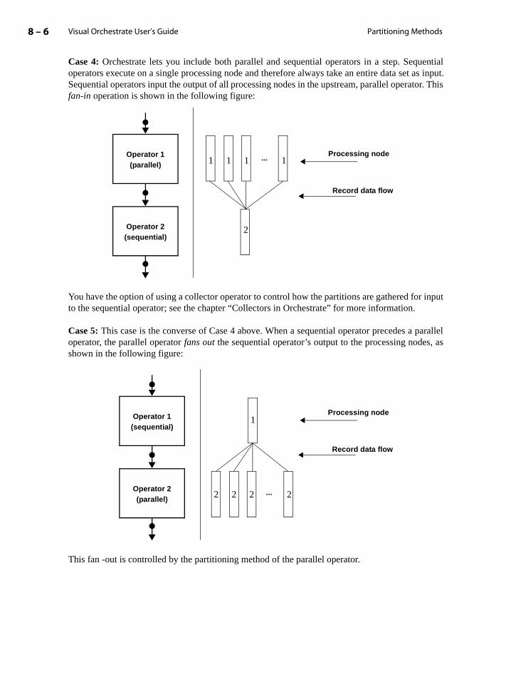
Visual Orchestrate User’s Guide8 – 6 Partitioning Methods
parallel, as
Case 4: Orchestrate lets you include both parallel and sequential operators in a step. Sequentialoperators execute on a single processing node and therefore always take an entire data set as input.Sequential operators input the output of all processing nodes in the upstream, parallel operator. Thisfan-in operation is shown in the following figure:
You have the option of using a collector operator to control how the partitions are gathered for inputto the sequential operator; see the chapter “Collectors in Orchestrate” for more information.
Case 5: This case is the converse of Case 4 above. When a sequential operator precedes aoperator, the parallel operator fans out the sequential operator’s output to the processing nodesshown in the following figure:
This fan -out is controlled by the partitioning method of the parallel operator.
Operator 1
Operator 2
(parallel)
(sequential)
Processing node
Record data flow
...1 1 1 1
2
Operator 1
Operator 2
Processing node
Record data flow
(sequential)
(parallel)...2 2 2 2
1

Partitioning in Orchestrate 8 – 7Visual Orchestrate User’s Guide
that
allows
“Parti-
te
tputrd
Using the Partitioning Operators
Nearly all Orchestrate built-in operators have a predefined partitioning method, Only the psortoperator and the group operator in hash mode. require that you specify a partitioning method.
Many Orchestrate operators have the predefined partitioning method any. You can place anypartitioning operator in front of an operator that specifies the any method. Overriding an operator’spartitioning method is useful for controlling the distribution of records in your system. Noteinserting a partitioning operator before an operator with a partitioning method other thananycauses an error.
You can also use a partitioning operator before you write a persistent data set to disk. This you to distribute your data set as a preprocessing operation before the write.
Orchestrate has a partitioning operator for each partitioning method described in the sectiontioning Method Overview” on page 8-4, as follows:
• roundrobin operator
• random operator
• same operator
• entire operator
• hash operator
• range operator
• modulus operator
For example, the following figure shows the roundrobin operator inserted before the Orchestrapcompress operator:
A benefit of the roundrobin operator is that it creates relatively equal-sized partitions in its oudata set. If processing previous to the roundrobin operator, such as a filter or duplicate-recoremoval, creates partitions that are unequal in size, you can use roundrobin to redistribute recordsbefore inputting them to the pcompress operator.
roundrobin operator
pcompress operator
Partitioning method = any
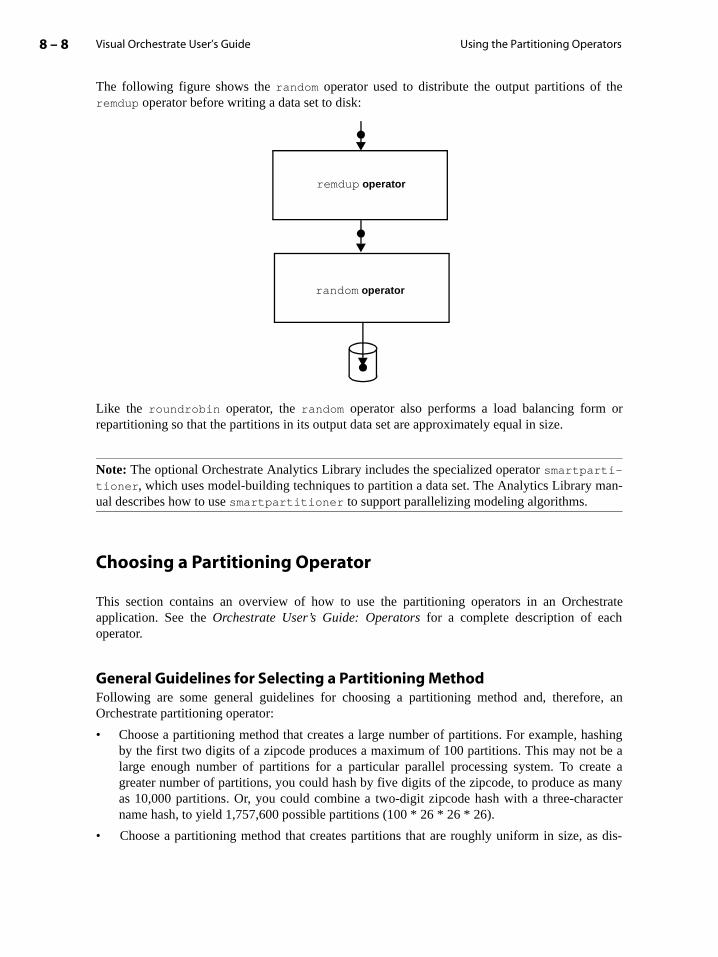
Visual Orchestrate User’s Guide8 – 8 Using the Partitioning Operators
ashing be aate a
manyracter
s dis-
The following figure shows the random operator used to distribute the output partitions of theremdup operator before writing a data set to disk:
Like the roundrobin operator, the random operator also performs a load balancing form orrepartitioning so that the partitions in its output data set are approximately equal in size.
Note: The optional Orchestrate Analytics Library includes the specialized operator smartparti-tioner, which uses model-building techniques to partition a data set. The Analytics Library man-ual describes how to use smartpartitioner to support parallelizing modeling algorithms.
Choosing a Partitioning Operator
This section contains an overview of how to use the partitioning operators in an Orchestrateapplication. See the Orchestrate User’s Guide: Operators for a complete description of eachoperator.
General Guidelines for Selecting a Partitioning MethodFollowing are some general guidelines for choosing a partitioning method and, therefore, anOrchestrate partitioning operator:
• Choose a partitioning method that creates a large number of partitions. For example, hby the first two digits of a zipcode produces a maximum of 100 partitions. This may notlarge enough number of partitions for a particular parallel processing system. To cregreater number of partitions, you could hash by five digits of the zipcode, to produce asas 10,000 partitions. Or, you could combine a two-digit zipcode hash with a three-chaname hash, to yield 1,757,600 possible partitions (100 * 26 * 26 * 26).
• Choose a partitioning method that creates partitions that are roughly uniform in size, a
remdup operator
random operator
Partitioning in Orchestrate 8 – 9Visual Orchestrate User’s Guide
ou aree same
pera-n eachgenum-
The
ration.aluese youhat all
ring or
t-name and,
ill be if youare fromad to.
cussed in the section “Partitioning Methods” on page 8-3.
• Make sure the partitioning method matches the action of the operator. For example, if yperforming a comparison, choose a partitioning scheme that assigns related records to thpartition, so the processing node can compare them.
• Do not use a complicated partitioning method with an operator that performs a uniform otion on all records, for example, extracting data. If the processing operation performed orecord is not related to any other records, use any. Remember that you are processing huamounts of data. Any additional processing on an individual record is multiplied by the ber of records in the data set.
Keyed and Keyless PartitioningKeyed partitioners examine one or more fields of a record, called the partitioning key fields, todetermine the partition to which to assign the record. The keyed partitioning operators are hash,modulus, and range.
Keyless operators determine the partition for a record without regard to the record itself.keyless partitioning operators are the random, roundrobin, and same.
The keyed partitioning operators hash and range are discussed in more detail below.
Hash PartitioningHash partitioning is useful when you need to compare records, such as in a sort or join opeYou use hash to hash-partition the data set, to assign records with the same partitioning key vare to the same partition. Then, you sort or join the individual partitions of the data set. Whilcannot control which partition receives which records, the hash partitioner guarantees trecords with the same hashing keys are assigned to the same partition.
You can also use hash partitioning when the processing operation relies on a particular orderelationship among the records of each partition. For example, suppose that you use the remdup
operator to remove duplicate records from a data set, according to the first-name and lasfields. If you randomly partition records, duplicate records might not be in the same partitiontherefore, would not be detected and removed.
While the hash partitioning operator guarantees that all records with the same hashing keys wassigned to the same partition, it does not control the size of each partition. For example,hash partition a data set based on a zipcode field, where a large percentage of your records one or two zipcodes, a few partitions will contain most of your records. This behavior can lebottlenecks because some nodes will be required to process more records than other nodes

Visual Orchestrate User’s Guide8 – 10 Using the Partitioning Operators
For example, the figure below shows the possible results of hash partitioning a data set using thefield age as the partitioning key:
The hash operator assigns records with the same age value to the same partition. As evident in thisfigure, the key values are randomly distributed among the partitions, but the number of keys perpartition is the same.
The partition sizes resulting from a hash partitioner depend on the distribution of records in the dataset. The example distribution shown above could be created when the data set contains an unequalrecord distribution based on the age field. Note that you may be able to choose a set of partitioningkeys for this example that creates equal-sized partitions. Or, your application may not care that thepartitions are of different sizes.
See the chapter on the hash operator in the Orchestrate User’s Guide: Operators for moreinformation.
Range PartitioningThe range partitioning operator guarantees that all records with the same partitioning key valuesare assigned to the same partition and that the partitions are approximately equal in size. Thismeans that all nodes perform an equal amount of work when processing the data set.
Using the range operator always results in partitions with a size distribution similar to that in thefigure below:
Partition number
Partition size(in records)
. . .
10
54
17
15
44
39
12
18
27
35
5
60
Age values
36
40
22
Partition
Partition size(in records)
. . .
Age values
0 - 2
3 -17
18 -25
26 -44
66 -71
Partitioning in Orchestrate 8 – 11Visual Orchestrate User’s Guide
te youring, asection
As shown in the figure, all partitions are approximately the same size. In an ideal distribution,every partition would be the same size. However, you will usually observe small differences inpartition size, based on your choice of partitioning keys.
In order to size the partitions, the range operator orders the partitioning keys. The range operatorthen calculates partition boundaries based on the partitioning keys in order to evenly distributerecords to the partitions. The above figure shows that the distribution of partitioning keys is noteven; that is, some partitions contain many partitioning keys, and others contain relatively few.However, based on the calculated partition boundaries, the number of records in each partition isapproximately the same.
The range operator offers the advantages of keyed partitioning, while guaranteeing similar-sizepartitions. The random and round robin partitioning method also guarantee that the partitions of adata set will be equivalent in size. However, these two partitioning methods are keyless and,therefore, do not allow you to control how the records of a data set are grouped within a partition.
See the chapter on the range operator in the Orchestrate User’s Guide: Operators details on usingthat operator.
The Preserve-Partitioning Flag
Some Orchestrate operators produce as output a data set with a specific partition layout. Forexample, the tsort operator produces a data set in which the records in each partition are sorted. Ifyou then use the output data set from tsort as input to an operator with a partitioning methodother than same, Orchestrate by default repartitions the data set and consequently destroys thesorted order of the records.
To let you control automatic repartitioning, Orchestrate provides the preserve-partitioning flag,which when set, prevents repartitioning of the data set. In some cases, Orchestrate automaticallysets the preserve-partitioning flag, and in others, you specify the flag’s setting when you creastep. Orchestrate’s setting of the preserve-partitioning flag and the propagation of the settwell as how you specify the setting when you create a step, are described in the s“Manipulating the Preserve-Partitioning Flag” on page 8-13.
Example of the Preserve-Partitioning Flag’s Effect
In the figure below, the data-flow diagram on the left shows the tsort operator outputting data thatis partitioned and sorted. The tsort output is then input to another operator, which has a partitioningmethod of any. The diagram in the middle shows that with the preserve-partitioning flag clear, the

Visual Orchestrate User’s Guide8 – 12 The Preserve-Partitioning Flag
data is automatically repartitioned before it is input to the operator. The right-hand diagram showsthat with the preserve-partitioning flag set, the partitioning is preserved.
Only operators that allow a partitioning method of any or same allow you to set the preserve-partitioning flag for an input data set. In fact, operators that specify the same partitioning methodissue a warning if the preserve-partitioning flag set is not set for an input data set. If the flag is setfor an input data set to a partitioning operator, Orchestrate issues a warning and repartitions the dataset.
The state of the preserve-partitioning flag is stored to disk along with the records of a persistentdata set. Therefore, when you read a persistent data set into Orchestrate, the saved state of thepreserve-partitioning flag will control how the data set is partitioned.
You need to be concerned with the preserve-partitioning flag only if you include operators in yourapplication that explicitly set the flag. Because most Orchestrate operators ignore the flag when ithas not been set, you can create an entire application without manipulating the flag.
Filtered data set
Sorted data set
Unsorted data set
tsort
Operator
Partitioning method=any. . .
. . .
. . .
. . .Processing nodes
Processing nodes
Record data flow
Preserve-partitioning flag = Clear
Preserve-partitioning flag = Set
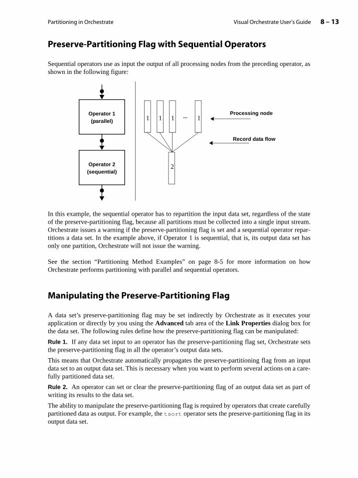
Partitioning in Orchestrate 8 – 13Visual Orchestrate User’s Guide
how
s your
d:
te sets
n inputn a care-
art of
refullyits
Preserve-Partitioning Flag with Sequential Operators
Sequential operators use as input the output of all processing nodes from the preceding operator, asshown in the following figure:
In this example, the sequential operator has to repartition the input data set, regardless of the stateof the preserve-partitioning flag, because all partitions must be collected into a single input stream.Orchestrate issues a warning if the preserve-partitioning flag is set and a sequential operator repar-titions a data set. In the example above, if Operator 1 is sequential, that is, its output data set hasonly one partition, Orchestrate will not issue the warning.
See the section “Partitioning Method Examples” on page 8-5 for more information on Orchestrate performs partitioning with parallel and sequential operators.
Manipulating the Preserve-Partitioning Flag
A data set’s preserve-partitioning flag may be set indirectly by Orchestrate as it executeapplication or directly by you using the Advanced tab area of the Link Properties dialog box forthe data set. The following rules define how the preserve-partitioning flag can be manipulate
Rule 1. If any data set input to an operator has the preserve-partitioning flag set, Orchestrathe preserve-partitioning flag in all the operator’s output data sets.
This means that Orchestrate automatically propagates the preserve-partitioning flag from adata set to an output data set. This is necessary when you want to perform several actions ofully partitioned data set.
Rule 2. An operator can set or clear the preserve-partitioning flag of an output data set as pwriting its results to the data set.
The ability to manipulate the preserve-partitioning flag is required by operators that create capartitioned data as output. For example, the tsort operator sets the preserve-partitioning flag in output data set.
Operator 1
Operator 2
(parallel)
(sequential)
Processing node
Record data flow
...1 1 1 1
2
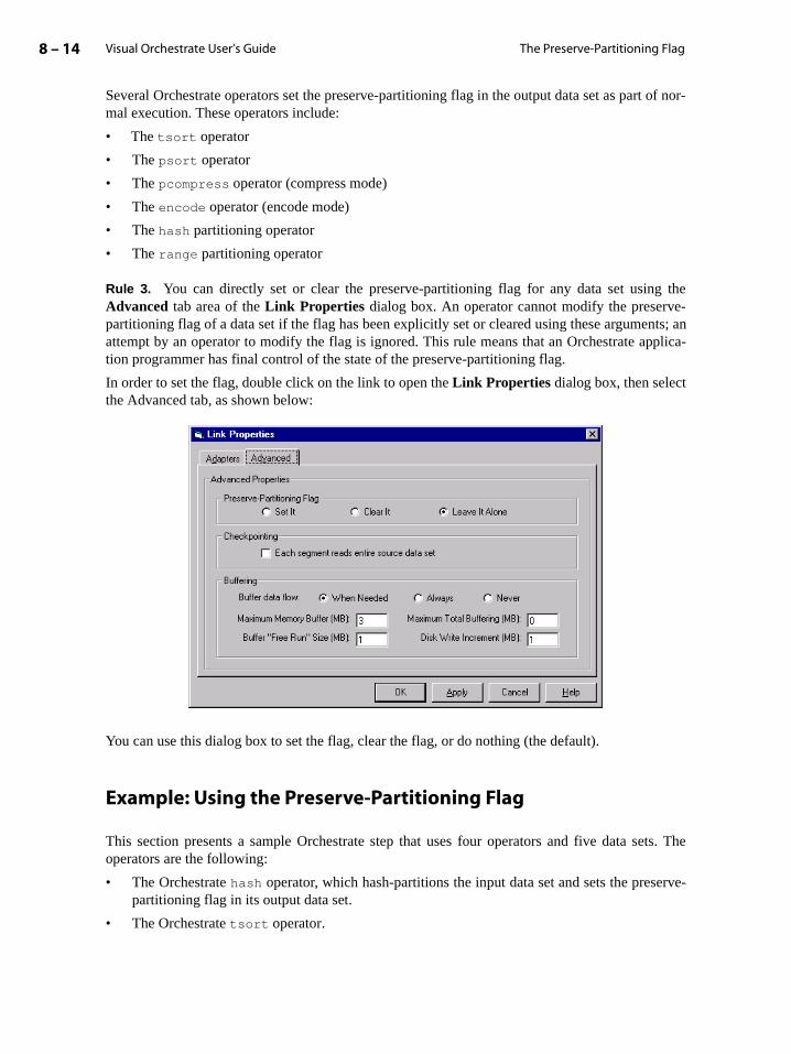
Visual Orchestrate User’s Guide8 – 14 The Preserve-Partitioning Flag
g thee-nts; anpplica-
ets. The
erve-
Several Orchestrate operators set the preserve-partitioning flag in the output data set as part of nor-mal execution. These operators include:
• The tsort operator
• The psort operator
• The pcompress operator (compress mode)
• The encode operator (encode mode)
• The hash partitioning operator
• The range partitioning operator
Rule 3. You can directly set or clear the preserve-partitioning flag for any data set usinAdvanced tab area of the Link Properties dialog box. An operator cannot modify the preservpartitioning flag of a data set if the flag has been explicitly set or cleared using these argumeattempt by an operator to modify the flag is ignored. This rule means that an Orchestrate ation programmer has final control of the state of the preserve-partitioning flag.
In order to set the flag, double click on the link to open the Link Properties dialog box, then selectthe Advanced tab, as shown below:
You can use this dialog box to set the flag, clear the flag, or do nothing (the default).
Example: Using the Preserve-Partitioning Flag
This section presents a sample Orchestrate step that uses four operators and five data soperators are the following:
• The Orchestrate hash operator, which hash-partitions the input data set and sets the prespartitioning flag in its output data set.
• The Orchestrate tsort operator.

Partitioning in Orchestrate 8 – 15Visual Orchestrate User’s Guide
sorted.
This
errid-therve-par-
• The Orchestrate remdup operator, which specifies a partitioning method of same. This opera-tor removes duplicate records from its input data set. The input data set is assumed to be
• ComputeOperator, a third-party operator which calculates values on an input data set. operator assumes no order in its input data set and defines its own partitioning method.
In this example, you manipulate the preserve-partitioning flag as required by each operator.
The figure below shows the data-flow diagram for this example:
The state of the preserve-partitioning flag for each of the data sets is described below:
1. The hash operator sets the preserve-partitioning flag in its output data set (Rule 2).
2. The tsort operator sets the preserve-partitioning flag on the output data set (Rule 2).
3. Note that you can explicitly clear the preserve-partitioning flag in the output data set, oving the default tsort setting (Rule 3). remdup creates a single output data set. Because input data set has its preserve-partitioning flag set, the output data set also has its presetitioning flag set (Rule 1).
unsortedDS.ds
Preserve-partitioning flag clearedVirtual data set
remdup operator
finalDS.ds
Partitioning method = same
ComputeOperator
Virtual data setPreserve-partitioning flag set
Preserve-partitioning flag cleared
1
Partitioning method = ????
tsort operator
hash operator
Virtual data setPreserve-partitioning flag set
2
3
4

Visual Orchestrate User’s Guide8 – 16 The Preserve-Partitioning Flag
4. However, the next operator, ComputeOperator, does not care about ordering to perform itsaction; therefore, ComputeOperator should be allowed to repartition its input data sets. Usethe Link Properties dialog box to clear the flag.ComputeOperator writes its output to a per-sistent data set. Since ComputeOperator takes as input a data set with the preserve-partition-ing flag cleared, and it does not modify the flag of its output data set (Rules 1 and 2), the flag iscleared in its output data set.
The state of the preserve-partitioning flag is stored to disk along with the records of the dataset.
This example shows how you can manipulate the preserve-partitioning flag as part of anOrchestrate application. Note, however, that the partitioning rules are designed so that your stepfunctions properly if you ignore the flag. However, because you limit the system ability torepartition data in this case, your application may not function as efficiently as possible.

9 – 1Visual Orchestrate User’s Guide
n
9: Collectors in Orchestrate
Partitioning is the process by which a parallel operator divides a data set into multiple seg-ments, or partitions. Each processing node in your system performs an operation on one par-tition of a data set, rather than on the entire data set. A collector defines how a sequentialoperator combines the partitions of an input data set for processing by a single node. Collect-ing for sequential operators is the inverse of partitioning for parallel operators.
Usually, a sequential operator defines its own collection algorithm or method, and you do nothave to modify this method. However, in certain circumstances Orchestrate gives you theoption of modifying an operator’s collection method.
Building on information in the chapter “Partitioning in Orchestrate”, this chapter describeshow sequential operators perform collection. It then describes how to select and use collectiooperators to modify the partitioning behavior of an operator. This chapter contains the fol-lowing sections:
• “Sequential Operators and Collectors” on page 9-1
• “Choosing a Collection Method” on page 9-3
• “Setting a Collection Method” on page 9-4
For details on using the Orchestrate operators described in this chapter, see the OrchestrateUser’s Guide: Operators.
Sequential Operators and Collectors
Orchestrate allows you to use both parallel and sequential operators in a step. Parallel operatorsexecute on multiple processing nodes, where each node receives a partition of an input data set.Sequential operators execute on a single processing node, which receives all partitions of an inputdata set.

Visual Orchestrate User’s Guide9 – 2 Sequential Operators and Collectors
g flaghod of
erve-erve-
on, no
When a sequential operator takes as input a data set with multiple partitions, the operator mustcombine all partitions into a single input stream. This fan-in operation is shown in the followingfigure:
In this figure, Operator 2 is a sequential operator that combines the partitions of its input data set.Once these partitions have been combined, all partition boundaries are lost. This process ofcombining the input partitions by a sequential operator is called collecting the partitions. Themechanism used by a sequential operator to combine the partitions is called a collector.
A collector defines the way a sequential operator combines the partitions of an input data set forprocessing by a single node. Collectors are the inverse of partitioners, which define how a paralleloperators distribute input data sets over multiple processing nodes.
Sequential operators offer various algorithms, called collection methods, that control the way anoperator combines partitions. A sequential operator with multiple inputs can define one collectionmethod for all input data sets, or it can use a different method for each input. The following sectiondescribes the collection methods available for sequential operators.
Sequential Operators and the Preserve-Partitioning Flag
As described in the chapter “Partitioning in Orchestrate”, you can set the preserve-partitioninfor a data set, to prevent its repartitioning by a parallel operator that uses a partitioning metany. However, the preserve-partitioning flag applies only to parallel operators.
A sequential operator repartitions an input data set without regard to the state of its prespartitioning flag. Before a sequential operator repartitions an input data set with its prespartitioning flag set, Orchestrate issues a warning. If the input data set has only one partitiwarning is issued.
Operator 1
Operator 2
(parallel)
(sequential)
Processing node
Record data flow
...1 1 1 1
2

Collectors in Orchestrate 9 – 3Visual Orchestrate User’s Guide
arst-d
d soition,
tion,s. In aes are
fields
ctor.
Collection Methods
A collection method may be as simple as combining the partitions on a first-come first-servedbasis, in which the sequential operator processes records in the order in which they are receivedfrom the preceding operator. More complex collection methods may determine the collection orderfrom information in the records of the data set.
Orchestrate also supports the following collection methods:
• Any: By default, Orchestrate built-in operators in sequential mode use the any collectionmethod. (The one exception is the group operator in sort mode, for which you must specifycollection method.) With the any method, the operator reads records on the first-come fiserved basis. Operators that use the any method allow you to override that collection methowith another.
• Round robin: Read a record from the first input partition, then from the second partition, anon. After reaching the last partition, start over. After reaching the final record in any partskip that partition in the remaining rounds.
• Ordered: Read all records from the first partition, then all records from the second partiand so on. This collection method preserves the order of totally sorted input data settotally sorted data set, both the records in each partition and the partitions themselvordered. See the chapters on the Sorting Library in the Orchestrate User’s Guide: Operatorsfor more information on totally sorting a data set.
• Sorted merge: Read records in an order based on one or more fields of the record. The used to define record order are called collecting keys. You use the sortmerge collection oper-ator to implement the sorted merge collection method.
• Other: You can define a custom collection method by deriving a class from APT_ColleOperators that use custom collectors have a collection method of other. See the chapter on col-lectors in the Orchestrate/APT Developer’s Guide for information on creating a collectionmethod.
Choosing a Collection Method
When you choose a collection method, take into account the particular action of its associatedoperator. The built-in collection methods any, round robin, and ordered are keyless. A keylesscollector does not rely on information in the records to define the order of records read by theoperator.

Visual Orchestrate User’s Guide9 – 4 Setting a Collection Method
tors:
Unless your sequential operator requires a deterministic order for processing records, the anycollection method is likely to serve your needs. For more control over the order of recordsprocessed by the operator, you can use the ordered method, the sortmerge collection operator, ora custom collector that you define.
Operators use any when the location of the record in the data set is irrelevant and the operatorperforms the same operation on every record. For example, in an unsorted data set, each record hasno relationship to the record immediately before or after it. When you specify any, your sequentialoperator is never forced to wait for a record from a particular partition.
The ordered method requires that all records are read from partition 0 before any records frompartition 1 are read. Even if all records of partition 1 are ready for processing before all records ofpartition 0, the sequential operator must wait in order to process the partitions in order, possiblycreating a processing bottleneck in your application. However, that the ordered collection methodis necessary if you want to preserve the sort order when you process a totally sorted data set with asequential operator.
Setting a Collection Method
To set an operator’s collection method, you use one of the three Orchestrate collection opera
• roundrobin_coll
• ordered
• sortmerge
These operators implement respectively the round robin, ordered, and sorted merge methods (seethe section “Collection Methods” on page 9-3).
The output of a collection operator must be one of the following:
• A virtual data set that is input to a sequential operator that uses the any collection method.
• A persistent data set. If the data set exists, it must contain only one partition.

Collectors in Orchestrate 9 – 5Visual Orchestrate User’s Guide
Collection Operator and Sequential Operator with Any Method
The output virtual data set from a collection operator overrides the collection method of an operatorusing the any collection method. For example, the following figure shows the ordered operatorinserted before the Orchestrate export operator:
This example uses the ordered operator to read all records from the first partition, then all recordsfrom the second partition, and so on. This collection method preserves the order of the input dataset that has been totally sorted. The export operator can then write the data set to a single data filethat contains ordered partitions.
Note: You can insert a collection operator before an operator that uses the any collection method.Inserting a collection operator before an operator with another collection method causes an error.
Collection Operator before Write to Persistent Data Set
You can insert a collection operator before the write operation to a persistent data set. Inserting acollection operator before the write operation allows you to control how the partitions of the dataset are collected for writing to a single partition.
ordered operator
export operator
Collection method = any
Data file

Visual Orchestrate User’s Guide9 – 6 Setting a Collection Method
For example, the following figure shows the sortmerge operator used to collect the outputpartitions of the remdup operator:
The sortmerge operator collects records based on one or more collecting keys.
remdup operator
sortmerge operator

10 – 1Visual Orchestrate User’s Guide
-
lt
rh ase
n
trateh nodeds the
ication
ake aart ans thetion
10: Constraints
A parallel processing system contains multiple processing nodes and multiple disk drives.Orchestrate’s view of your system is controlled by the contents of the Orchestrate configuration file.
The configuration file includes definitions for the default node and disk pools. Most Orches-trate operators by default execute on all processing nodes that are members of the defaunode pool. In addition, Orchestrate data sets are stored on all disk drives in the default diskpool.
However, you can limit the processing nodes used by a specific operator or an entire step othe disks used to store a data set. For example, an operator may use system resources, suca tape drive, not available to all nodes, or the action of the operator may be memory intensivand you want to execute the operator only on nodes with a large amount of memory.
To limit an operator or step to specific processing nodes, you impose a constraint. A constraintconfigures an operator or step to execute only on a particular set of processing nodes. You caalso constrain a data set to a specific set of disks on a specific set of processing nodes.
This chapter first introduces constraints, then describes how to apply constraints to both youcode and to your data. The chapter contains the following sections:
• “Using Constraints” on page 10-1
• “Using Constraints with Operators and Steps” on page 10-5
• “Data Set Constraints” on page 10-9
Using Constraints
An Orchestrate application’s view of your system is defined by the current Orchesconfiguration file. This file describes the processing nodes and disks drives connected to eacallocated for use by Orchestrate. Whenever it invokes an application, Orchestrate first reaconfiguration file to determine allocated system resources, and it then distributes the applaccordingly.
Whenever you modify your system by adding or removing nodes and disks, you need to mcorresponding modification to the Orchestrate configuration file. Then, the next time you stapplication, Orchestrate reads the modified configuration file and automatically scaleapplication to fit the new system configuration, without requiring you to modify the applicaitself.

Visual Orchestrate User’s Guide10 – 2 Using Constraints
ount ofld beuiring
h you
For example, the following figure shows a six-node MPP system, with four nodes configured aslogical nodes for Orchestrate applications:
In this configuration, Orchestrate applications run on nodes 0 and 1 and I/O nodes 0 and 1, but noton nodes 2 and 3. Suppose your system gains a node, node4 (with processor and disk), that youwant Orchestrate to use in running your application. You modify your configuration file to allocatenode4 for Orchestrate processing and I/O. Then, on its next run your application would use node4according to your modified configuration file.
See the Orchestrate Installation and Administration Manual for detailed information on creatingand administering configuration files.
Controlling Where Your Code Executes on a Parallel System
The Orchestrate configuration file provides a great deal of flexibility in controlling the processingnodes that execute your application and the disk drives that store your data. All the processingnodes in your system may not be identically configured — some nodes may have a large amdata storage, while other nodes have a large amount of physical memory that couadvantageous in performing complex calculations. Your application may use an operator reqa particular system resource, such as a tape drive, that is not available to all nodes.
You can use the Orchestrate configuration file to define subgroups of nodes, called node pools,within your group of logical nodes. Using node pools, you select the specific nodes on whicwant to perform certain actions.
High-speed network
node0 node1 node2 node3ionode0 ionode1
CPUCPU CPU CPUCPUCPU
Orchestrate logical nodes

Constraints 10 – 3Visual Orchestrate User’s Guide
ecificecified
tor. A over-.
ation
ystemw node
The following figure shows an example of the nodes specified for use by Orchestrate applications:
In this example, the group of Orchestrate logical nodes is divided into two node pools: computenodes and I/O nodes. A processing node may be a member of multiple pools; in this example,node1 is part of both the compute node pool and the I/O node pool.
You can choose to execute an entire step, or any operator within the step, on all four processingnodes or on either node pool. Specifying the processing nodes that execute your application iscalled constraining the application. A node pool constraint limits execution (processing and I/O) tothe nodes in the pool(s) that you allocate to the step or operator.
You can apply two other types of constraints to control the processing nodes that execute yourcode:
• Resource constraints limit the execution of an operator or step to nodes that have a spresource, such as a disk or scratch disk (for temporary storage), or a resource in a spresource pool.
• Node map constraints specify the list of processing nodes for a specific run of an operanode map constraint applies only to the particular operator invocation and while in effect,rides any other constraint (node pool or other resource) previously specified for the step
See the section “Using Constraints with Operators and Steps” on page 10-5 for more informon all three types of constraints.
Using Node Constraints on a Stand-alone SMPA stand-alone SMP (symmetric multiprocessing system) uses multiple CPUs that share sresources such as memory, disk drives, and network connection. This section describes hoconstraints affect application execution on a stand-alone SMP.
High-speed network
node0 node1 node2 node3ionode0 ionode1
CPUCPU CPU CPUCPUCPU
Compute node pool
Orchestrate logical nodes
I/O node pool
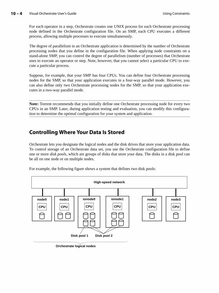
Visual Orchestrate User’s Guide10 – 4 Using Constraints
For each operator in a step, Orchestrate creates one UNIX process for each Orchestrate processingnode defined in the Orchestrate configuration file. On an SMP, each CPU executes a differentprocess, allowing multiple processes to execute simultaneously.
The degree of parallelism in an Orchestrate application is determined by the number of Orchestrateprocessing nodes that you define in the configuration file. When applying node constraints on astand-alone SMP, you can control the degree of parallelism (number of processes) that Orchestrateuses to execute an operator or step. Note, however, that you cannot select a particular CPU to exe-cute a particular process.
Suppose, for example, that your SMP has four CPUs. You can define four Orchestrate processingnodes for the SMP, so that your application executes in a four-way parallel mode. However, youcan also define only two Orchestrate processing nodes for the SMP, so that your application exe-cutes in a two-way parallel mode.
Note: Torrent recommends that you initially define one Orchestrate processing node for every twoCPUs in an SMP. Later, during application testing and evaluation, you can modify this configura-tion to determine the optimal configuration for your system and application.
Controlling Where Your Data Is Stored
Orchestrate lets you designate the logical nodes and the disk drives that store your application data.To control storage of an Orchestrate data set, you use the Orchestrate configuration file to defineone or more disk pools, which are groups of disks that store your data. The disks in a disk pool canbe all on one node or on multiple nodes.
For example, the following figure shows a system that defines two disk pools:
High-speed network
node0 node1 node2 node3ionode0 ionode1
CPUCPU CPU CPUCPUCPU
Disk pool 2Disk pool 1
Orchestrate logical nodes

Constraints 10 – 5Visual Orchestrate User’s Guide
traints”
n firstetails
in stor-
by an shown
at-
disk’ssst it.
In this example, ionode0 has one disk in disk pool 1 and two disks in disk pool 2. Also, ionode1has two disks in disk pool 2.
You can constrain an operator to use a particular disk pool; see the section “Data Set Conson page 10-9 for more information.
Using Constraints with Operators and Steps
You use the Orchestrate configuration file to set up node pools and disk pools. This sectiobriefly describes how to use your configuration file to set up node pools and disk pools. (For don configuration file statements, see the Orchestrate Installation and Administration Manual.) Itthen describes how to use the constraints in execution of steps and individual operators andage of your data.
Configuring Orchestrate Logical Nodes
The configuration file contains a node definition for each logical node that can be used Orchestrate application. The node definition can specify node pools and resource pools, asin the following example:
node "node0" {fastname "node0_css" pools "" "node0" "node0_css" "compute_node" /* node pools */resource disk "/orch/s0" {pools "" "pool1"}resource scratchdisk "/scratch" {}
}
In this example:
• The node argument, node0, is the node name.
• The fastname argument, node0_css, is the name used internally for data transfers.
• The pools option lists the node pools of which this node is a member.
The first argument "" is the default node pool; the other arguments are node pools node0,node0_css, and compute_node. If you do not assign a node to any node pools, it is automically a member of the default node pool.
• The resource resource_type "directory" {resource_pools p1...pn} optiondefines a disk or scratch disk connected to the node. You can optionally specify the membership in non-default disk pools by including a pools clause inside the required brace{}; if you also want the disk or scratch disk to belong to the default disk pool, you must liWithout a pools clause, the disk is automatically a member of the default disk pool.
In the example, the resource disk clause assigns file directory /orch/s0 to this node forpermanent storage, and assigns the disk to the default pool and to pool1. The resourcescratchdisk clause assigns to this node the file directory /scratch, for temporary storage;the empty braces {} indicate that the scratch disk is in the default scratch disk pool only.

Visual Orchestrate User’s Guide10 – 6 Using Constraints with Operators and Steps
Using Node Pool Constraints
After you have defined a node pool, you can constrain an Orchestrate operator or an entireOrchestrate step to execute on only the processing nodes in the node pool.
To set a node pool constraint on an operator:
1. Double click the operator in the Program Editor to open the Operator Properties dialog box.
2. Click the Advanced tab.
3. Click the Add button under Constraints to add a new constraint, using the following dialogbox:
4. Select Node Pool from the Constraint Type pull-down list.
5. Select the Orchestrate configuration from the Config Name list, containing the names ofOrchestrate configuration files (created by the Orchestrate server administrator).
6. Enter the node pool name in the Pool Name area. You can enter multiple node pool names,separated by commas. For example, to specify the node pool compute_node, you enter:
Pool Name: compute_node
In addition, you can constrain an entire step to a node pool. To constrain a step, double click thestep in the Program Editor to open the Step Properties dialog box. In that dialog box, choose theConstraints tab to set a node pool constraint for all the operators in a step.
Multiple node pool constraints are ANDed together, so that a node must meet all constraints inorder to process the operator. For example, the following command constrains an operator to allnodes in both the compute_node and io_node node pools:
Pool Name: compute_node, io_node
In this case, only node1 satisfies both constraints; therefore, the operator executes only on node1.
You can combine the nodepool and resources statements to combine constraints. See thesection “Combining Node and Resource Constraints” on page 10-8 for more information.

Constraints 10 – 7Visual Orchestrate User’s Guide
ia-
source
double
ies both
Using Resource Constraints
Each processing node in your system can have access to specific resources. Orchestrate allows youto impose constraints on operators based on node resources. As described in the section“Configuring Orchestrate Logical Nodes” on page 10-5, the resource disk and resourcescratchdisk options allow you to specify pools for each type of disk storage.
To set a resource constraint on an operator:
1. Double click the operator in the Program Editor to open the Operator Properties dialog box.
2. Click the Advanced tab.
3. Click the Add button under Constraints to add a new constraint. This opens the following dlog box:
4. Select Resource Pool from the Constraint Type pull down list.
5. Select the Orchestrate configuration from the Config Name list. A configuration correspondsto a configuration file and is created by the Orchestrate server administrator.
6. Enter the resource pool type and name under Resource Pool Constraint. You can enter multi-ple pool names, separated by commas.
The following example constrains an operator to execute only on those nodes with a disk rein the pool pool1:
Pool Type: disk
Pool Name: pool1
In addition, you can constrain an entire step to a resource pool. In order to constrain a step,click a step in the Program Editor to open the Step Properties dialog box. Then choose theConstraints tab to set a resource pool constraint for all the operators in a step.
Orchestrate applies all resource constraints, so that a node must have a disk that satisfconstraints in order to execute the operator. In this case, only ionode0 has a disk in both pool1and pool2 and is therefore the only node to execute the operator.

Visual Orchestrate User’s Guide10 – 8 Using Constraints with Operators and Steps
The following example constrains an operator to the nodes with a disk resource in pool1 andpool2:
Pool Type: disk
Pool Name: pool1, pool2
Combining Node and Resource Constraints
You can combine node and resource constraints. Node and resource constraints are ANDedtogether; a node must meet all constraints in order to execute the operator.
To combine constraints, you use the Constraint Editor for either a step or an operator to set bothNode Pool and Resource Pool constraints. The following example sets both a node and a resourceconstraint:
Node Pool:Pool Name: compute_node
Resource Pool:
Pool Type: disk
Pool Name: pool1
In this example, only node1 is in the compute_node pool and has a disk in pool1.
Using Node Maps
Node maps allow you to constrain a particular run of an operator to execute on a specific set ofprocessing nodes. A node map applies to an operator invocation overrides any node pool orresource pool constraint applied to the operator or to its step. You cannot combine node maps withany other type of constraint.
To set a node map constraint on an operator:
1. Double click the operator in the Program Editor to open the Operator Properties dialog box.
2. Click the Advanced tab.
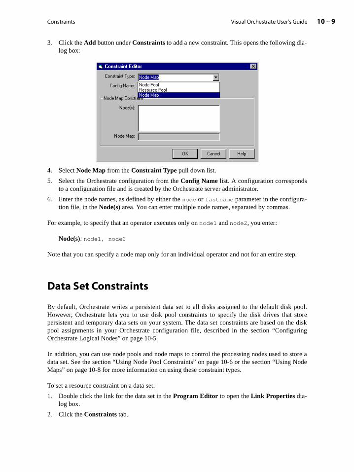
Constraints 10 – 9Visual Orchestrate User’s Guide
uring
store a Node
3. Click the Add button under Constraints to add a new constraint. This opens the following dia-log box:
4. Select Node Map from the Constraint Type pull down list.
5. Select the Orchestrate configuration from the Config Name list. A configuration correspondsto a configuration file and is created by the Orchestrate server administrator.
6. Enter the node names, as defined by either the node or fastname parameter in the configura-tion file, in the Node(s) area. You can enter multiple node names, separated by commas.
For example, to specify that an operator executes only on node1 and node2, you enter:
Node(s): node1, node2
Note that you can specify a node map only for an individual operator and not for an entire step.
Data Set Constraints
By default, Orchestrate writes a persistent data set to all disks assigned to the default disk pool.However, Orchestrate lets you to use disk pool constraints to specify the disk drives that storepersistent and temporary data sets on your system. The data set constraints are based on the diskpool assignments in your Orchestrate configuration file, described in the section “ConfigOrchestrate Logical Nodes” on page 10-5.
In addition, you can use node pools and node maps to control the processing nodes used todata set. See the section “Using Node Pool Constraints” on page 10-6 or the section “UsingMaps” on page 10-8 for more information on using these constraint types.
To set a resource constraint on a data set:
1. Double click the link for the data set in the Program Editor to open the Link Properties dia-log box.
2. Click the Constraints tab.
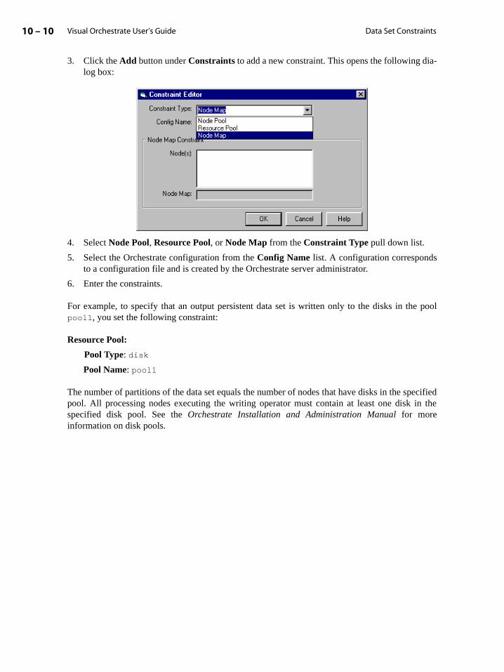
Visual Orchestrate User’s Guide10 – 10 Data Set Constraints
3. Click the Add button under Constraints to add a new constraint. This opens the following dia-log box:
4. Select Node Pool, Resource Pool, or Node Map from the Constraint Type pull down list.
5. Select the Orchestrate configuration from the Config Name list. A configuration correspondsto a configuration file and is created by the Orchestrate server administrator.
6. Enter the constraints.
For example, to specify that an output persistent data set is written only to the disks in the poolpool1, you set the following constraint:
Resource Pool:
Pool Type: disk
Pool Name: pool1
The number of partitions of the data set equals the number of nodes that have disks in the specifiedpool. All processing nodes executing the writing operator must contain at least one disk in thespecified disk pool. See the Orchestrate Installation and Administration Manual for moreinformation on disk pools.
11 – 1Visual Orchestrate User’s Guide
or error
estrate
n and
allowsility,essageg in
copy the
error
11: Run-Time Error and Warning Messages
During execution of your application, Orchestrate detects and reports error and warningconditions. This chapter describes the format of Orchestrate warning and error messages anddescribes how to control the format of message display, in the following sections:
• “How Orchestrate Detects and Reports Errors” on page 11-1
• “Error and Warning Message Format” on page 11-2
• “Controlling the Format of Message Display” on page 11-4
How Orchestrate Detects and Reports ErrorsDuring execution of your application, Orchestrate detects error and warning conditions, which canbe generated by the following:
• Orchestrate operators, used in your application steps. For details on Orchestrate operatmessages, see the Orchestrate User’s Guide: Operators.
• Your application code, outside the Orchestrate steps. For information on using the Orcherror-handling class, see the Orchestrate/APT Developer’s Guide.
• Subprocesses in your application, including wrappers and third-party applications.
When Orchestrate detects an error or warning condition, it writes the applicable informatiomessage to the error log.
If the condition is not severe, after writing a warning message to the error log, Orchestrate the application to continue execution. At various points in running an application or utOrchestrate checks the error log for new entries. It writes new warning messages to the mwindow on the screen of the workstation from which you invoked the application. Right-clickinthe message window pops up a menu of standard commands that you can use to edit and messages.
If the condition is so severe that application execution cannot continue, after writing anmessage, Orchestrate terminates the application.

Visual Orchestrate User’s Guide11 – 2 Error and Warning Message Format
ee the
thersiable-
ponents.ge text,
Error and Warning Message Format
The table below lists the components of Orchestrate error and warning messages, as follows:
• The first column shows whether the default is on or off for display of the component.
• The second column is the keyword (case-insensitive) for changing the default display (ssection “Controlling the Format of Message Display” on page 11-4).
• The third column is the component length, which for some components is fixed and for ois variable. Orchestrate left-pads with zeros all fixed-length components. For any varlength component, you can configure Orchestrate to display the component length.
• The last column describes the component.
Note that except where indicated, there is a one-space separator between message comEvery message is terminated with a newline. Only the last message component, the messamay contain spaces.
Default Display Keyword Length Description
On 2 The string "##". You cannot suppress display of this component.
0 [No separator]
On severity 1 Severity of condition: "F", "E", "W", or "I", for Fatal, Error, Warning, or Informational mes-sage.
Off vseverity 7 Verbose severity indicator: "Fatal", "Error", "Warning", or "Inform".
Off jobid 3 Job identifier of the Orchestrate application, to let you identify concurrently running Orches-trate applications. The default job ID is 0.
On moduleId 4 Module identifier, which is one of the follow-ing:
For Orchestrate-defined error messages, a four-character string beginning with "T".
For user-defined error messages, the string "USER".
For a message from a subprocess, the string "USBP".
0 [No separator]
On errorIndex 6 Index of the message at the time it was written.
On timestamp 13 Message time stamp, consisting of the string "HH:MM:SS(msg_seq)", which is the hour, minute, second, and message sequence number at the time the message was written.
Note that error messages written within one second have ordered sequence numbers.

Run-Time Error and Warning Messages 11 – 3Visual Orchestrate User’s Guide
lays themodule
Messages from Subprocesses
The message display configuration also controls display of error messages from subprocesses runby Orchestrate, including wrappers and third-party applications. Orchestrate catches subprocessmessages written to the subprocess’s standard output or standard error. Orchestrate dispmessages using the current message display configuration, on a per-line basis. The
Off ipaddr 15 IP address of the node generating the message. This 15-character string is in octet form, with octets zero-filled; e.g., 104.032.007.100.
Off lengthprefix 2 Length in bytes of the following field, nodeplayer.
Off nodeplayer Variable String "(node,player)", containing the number of the section leader and player that generated the message.
Off lengthprefix 2 Length in bytes of the following field, nodename.
Off nodename Variable Name of the node generating the message.
Off lengthprefix 2 Length in bytes of the following field, opid.
On opid Variable Operator identifier, which is one of the follow-ing:
For messages originating in the main program (not in a step), the string "<main_program>".
For system messages originating on a node, the string "<node_nodename>", where node-name is the name of the node.
For messages originating in a step, the operator originator identifier, which identifies the instance of the operator that generated the mes-sage. This identifier is the string "ident, partition_n". ident is the operator name. If there is more than one instance of the opera-tor, ident includes an operator index in parentheses. partition_n identifies the par-tition of the operator issuing the message. An example of an opid originating in a osh step is <myop,4>
Off lengthprefix 5 Length in bytes of the following field, mes-sage.
On message Variable Text of the message. Maximum message length is 15 KBytes.
1 Newline
Default Display Keyword Length Description

Visual Orchestrate User’s Guide11 – 4 Controlling the Format of Message Display
identifier for all subprocess output is "USBP". Orchestrate gives messages written to standardoutput Informational severity and a message index of 1. Orchestrate gives messages written tostandard error Warning severity and a message index of 2.
Controlling the Format of Message Display
The following is an example of a warning message with all its components displayed:
##I Inform 000 TOSH000010 10:46:15(001) 010.000.002.119 05 (0,0) 09 localhost 14 <main_program> 00016 orchsort: loaded
You can limit the message components that Orchestrate displays. Suppose, for example, that youlimit the display of the sample warning message above to message severity, module and index, pro-cessing node, operator identifier, and message text. Orchestrate would then display the message asfollows:
##I TOSH000010 localhost <main_program> orchsort: loaded
You use keywords to control message display. Specifying an unmodified keyword configuresOrchestrate to display the associated message component. Preceding the keyword with anexclamation point (!) configures Orchestrate to suppress display of the associated component.
For example, shown below is the default message configuration for all messages originating fromOrchestrate applications:
severity, !vseverity, !jobid, moduleid, errorIndex, timestamp, !ipaddr, !nodeplayer, !nodename, opid, message, !lengthprefix
This example specifies suppression of the display of verbose severity, job identifier, IP address,node name, and length prefixes are all suppressed.
The display of messages from Orchestrate command utilities (such as buildop and cbuildop)has the following default:
severity, !vseverity, !jobid, moduleid, errorIndex, !timestamp, !ipaddr, !nodeplayer, !nodename, !opid, message, !lengthprefix
For messages from command utilities, Orchestrate suppresses the display of verbose severity, jobidentifier, time, IP address, node player, node name, operator identifier, and length prefixes.
To control message display format, you use the APT_ERROR_CONFIGURATION environmentvariable.
For further details on APT_ERROR_CONFIGURATION and other environment variables, see theOrchestrate Installation and Administration Manual.
The environment variable APT_ERROR_CONFIGURATION lets you configure error and warningmessage display for all Orchestrate applications and utilities. To use the variable

Run-Time Error and Warning Messages 11 – 5Visual Orchestrate User’s Guide
11-2.ain
the
the
,
tweene sure
e to the
APT_ERROR_CONFIGURATION, you issue a UNIX command to set it to a string containing thecomponent keywords defined in the section “Error and Warning Message Format” on pageAny keywords omitted from your command to set APT_ERROR_CONFIGURATION remunchanged from their previous state.
For example, the following commands set and export APT_ERROR_CONFIGURATION, insyntax for the Korn and Bourne shells:
APT_ERROR_CONFIGURATION=’! severity, ! timestamp, ipaddr, nodename’
export APT_ERROR_CONFIGURATION
Following is the equivalent command to set and export APT_ERROR_CONFIGURATION, insyntax for the C shell:
setenv APT_ERROR_CONFIGURATION "\! severity, \! timestamp, ipaddr, nodename’"
In the C shell command, you must precede an exclamation point (!) with the escape characterbackslash (\).
In both versions of the command to set APT_ERROR_CONFIGURATION, note the space bethe exclamation point and the keyword. It is recommended that you insert this space, to makthat the command shell does not interpret the exclamation point and keyword as a referenccommand history buffer.

Visual Orchestrate User’s Guide11 – 6 Controlling the Format of Message Display
12 – 1Visual Orchestrate User’s Guide
12: Creating Custom Operators
Many Orchestrate applications require specialized operators to perform application-specificdata processing, in parallel. You may need an operator to perform a simple operation such asadding two particular fields. Or, you may need an operator to carry out a much more com-plex task.
Visual Orchestrate gives you the ability to create two kinds of custom operators: native oper-ators and UNIX command operators. This chapter describes how to create native operators,for which you supply a few C or C++ statements to perform the operator’s action. (CreatingUNIX command operators is described in the chapter “Creating UNIX Operators”.)
This chapter includes the following sections:
• “Custom Orchestrate Operators” on page 12-1
• “Using Visual Orchestrate to Create an Operator” on page 12-5
• “Specifying Operator Input and Output Interfaces” on page 12-8
• “Examples of Custom Operators” on page 12-14
• “Using Orchestrate Data Types in Your Operator” on page 12-20
• “Using the Custom Operator Macros” on page 12-27
• “How Visual Orchestrate Executes Generated Code” on page 12-31
• “Designing Operators with Multiple Inputs” on page 12-31
Custom Orchestrate Operators
Visual Orchestrate lets you create custom (native) operators by supplying only a few lines of C orC++ code for the operator body, and some configuration information. From this information,Orchestrate creates the operator by automatically generating C/C++ code, and then compiling andlinking the operator.
This section describes the characteristics of the custom operators that you can create. It thendescribes how custom operators perform input and output and process data.

Visual Orchestrate User’s Guide12 – 2 Custom Orchestrate Operators
ave mul-ws a
de to
-dify
et, as
ma as
on page
n users
Kinds of Operators You Can Create
Orchestrate allows you to create custom operators with the following characteristics:
• The operator has at least one input data set and one output data set. The operator can htiple input data sets and multiple output data sets. The following data flow diagram shocustom operator with multiple inputs and outputs:
• By default, the operator’s execution mode is parallel. However, you can override this mospecify sequential execution when you use the operator in a step.
• The default partitioning method of the operator is any (parallel mode), and the default collection method is any (sequential mode). You can use a partitioner or collector operator to mothese defaults.
• You can optionally define a transfer to copy an entire input record to an output data sshown in the data-flow diagram below:
Note that the transferred record is represented in the operator input interface scheinRec:*, and in the output interface schema as outRec:*. For a complete description of theOrchestrate transfer feature, see the section “Record Transfers and Schema Variables” 5-11.
• You can define user-settable options, or arguments, passed to an operator. Then, wheinsert the operator into a step, they can set those control options by using the Options Editordialog box.
. . .
. . .
Input data sets
Output data sets
Custom operator
inRec:*
Output data set
Input data set
outRec:*

Creating Custom Operators 12 – 3Visual Orchestrate User’s Guide
How a Generated Operator Processes Data
To plan and create an operator, you need to understand how Orchestrate operators process one ormore input data sets and create one or more output data sets. This section describes this operation.
The following figure shows an operator with a single input and a single output data set:
An operator executes an I/O and processing loop, with iteration (time through the loop) for everyinput record. After all the required number of input records have been read from one or moreinputs, the operator terminates.
How the Operator Executes the LoopFor each input record, the operator executes the following steps in the I/O and processing loop:
1. Reads a record from the input data set (unless there are no remaining records or automatic readhas been disabled).
2. Performs the action of the operator.
3. As needed, assigns results to the current output record.
4. If specified, performs a transfer of the entire input record to the output record (unless there areno more records to transfer or automatic transfer has been disabled).
5. Writes the current output record to the output data set (unless automatic write has been dis-abled).
Note that your operator does not have to produce one output record for each input record. Someoperators read multiple input records before producing a single output record, such as an operatorthat removes duplicate records from the input data set. Other types of operators can create multipleoutput records from a single input record.
Input data set
Output data set...
Input data set
Operator
Previously processed input records
.
.
.(not available)
.
.
.
.
.
.
Previously writtenoutput records(not available)
Output data set
Current output record
Current input record
Order of record writeOrder of record read
Visual Orchestrate User’s Guide12 – 4 Custom Orchestrate Operators
erfacer more
to the a new hasrd.
tting.efault Data
ry UNIXkages,
access
of the-13.
omati-
How the Operator Processes the Input Data SetsAn operator reads each input data set record by record, to process its data. The operator continuesto read and process records until it has read all records in the input data set. Once the operator hasmoved beyond a record of an input data set, it can no longer access that record.
Note that the fields of all input data sets are read-only, while the fields of all output data sets arereadable and writable.
How the Operator Writes to the Output Data SetIn creating your operator, you define the operator’s input interface schema and output intschema. See the section “Specifying Operator Input and Output Interfaces” on page 12-8 foinformation.
After the operator assigns the processing results to the record fields, it writes the recordoutput data set. Writing the output record commits the record to the data set, and it createsoutput record with default values for all fields. As with input data sets, once processingadvanced beyond a record of an output data set, the operator can no longer access the reco
The default value for an output record field is based on the field’s data type and nullability seFor a complete list of default values for fields of all types, see the description. For a list of dvalues for fields of all types, see the section the section “Default Values for Fields in OutputSets” on page 4-27.
Configuring Orchestrate For Creating Operators
To allow creation of operators, the Orchestrate server must be able to access the necessaC++ compiler and other utilities. The appendix on supported operating systems, software pacand databases in the Orchestrate Installation and Administration Manual lists these compilers andutilties.Your Orchestrate server administrator must ensure that you have the correct privileges and path settings to run these utilities.
You can specify a non-default compiler for your custom operators, by using the Paths tab Program Properties dialog box. See the section “Setting Program Directory Paths” on page 2
Included Header FilesThe custom operator utility lets you to use standard I/O, I/O stream, and math functions autcally. In order to do so, the utility includes the following header files:
• stdio.h
• iostream.h
• math.h
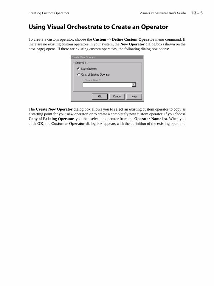
Creating Custom Operators 12 – 5Visual Orchestrate User’s Guide
Using Visual Orchestrate to Create an Operator
To create a custom operator, choose the Custom -> Define Custom Operator menu command. Ifthere are no existing custom operators in your system, the New Operator dialog box (shown on thenext page) opens. If there are existing custom operators, the following dialog box opens:
The Create New Operator dialog box allows you to select an existing custom operator to copy asa starting point for your new operator, or to create a completely new custom operator. If you chooseCopy of Existing Operator, you then select an operator from the Operator Name list. When youclick OK, the Customer Operator dialog box appears with the definition of the existing operator.

Visual Orchestrate User’s Guide12 – 6 Using Visual Orchestrate to Create an Operator
uts for
erfacesection
This
If in the Create New Operator dialog box you select New Operator, clicking OK opens an emptyCustom Operator dialog box, as shown below
By default, the Native Operator radio button is selected. The Library text box defaults to youruser name. You can type in a new library name or the name of any existing library.
In the Name text box (upper left of dialog box), type the name of this operator. A name can be up to250 characters long. An operator name must be unique within its library, but it can be the same asthe name of an operator in another library.
You define the operator by using the Custom Operator dialog box tabs, as follows:
Interfaces (shown above): Specify the names and schemas of the operator’s inputs and outpthe operator input and output interfaces.
Specifying your operator interface schemas is described in the section “Specifying the IntSchema” on page 12-10. Also specify and configure record transfers, as described in the “Defining Transfers” on page 12-13.
Per-record: Specify the code loop, which is executed once for every input record.
Definitions: Optionally, specify definitions to include before the operator’s executable code. option allows you to specify header files or other information needed to compile your code.
Native Operator selected
Creating Custom Operators 12 – 7Visual Orchestrate User’s Guide
underdicate-
n. The
By default, Orchestrate always includes the header files stdio.h, iostream.h, and math.h.
Pre-loop: Optionally, specify code to execute before the operator executes the Per-record code toprocess the record. You can use this code section to initialize variables used in the Per-record sec-tion.
Post-loop: Optionally, specify code to execute after the operator has completed the Per-record sec-tion and before the operator terminates.
Misc: Optionally, specify the following options for operator execution:
Operator Execution Mode: You can select Parallel, Sequential, or Operator Default(default for this option). Specifying Operator Default allows the operator user to set the exe-cution mode upon inserting the operator into a step.
Compiler Options: You can specify options passed to the C++ compiler (and linker) used tocreate the operator:
Verbose: Echoes commands and compiler messages to the message window.
Debug: Runs the compiler in debug mode.
Optimize: Optimizes the speed and efficiency of the compiled code.
Additional Compiler Flags: You can specify additional compiler command options.
Additional Linker Flags: You can specify additional linker command options.
Operator Description: Optionally, type your notes about this operator, to be saved with theoperator definition. Right-clicking the text box opens a menu of standard text-editing com-mands, such as cut and paste.
Options: Optionally, define user-settable controls for the operator, with which the operator user cancontrol the action of the operator.
Access: Set the access privileges of the operator, by selecting one of the following:
Public Write (default): Anyone can read, write, or execute the operator.
Public Read: Anyone can read and execute the operator; only the operator creator can modifyit.
Private: Only the operator creator can read, write, or execute the operator.
At any time after you have specified a name and library for the operator, you select a dialog boxbuttons to do one of the following:
• Save the information about the operator, but do not create it. A saved operator appearsthe specified library in the Server View area of Visual Orchestrate in parentheses, to inthat the operator user cannot use it. (You must press Create to make it usable in an application.)
• Create the operator, so that an operator user can insert it into an Orchestrate applicatiocreated operator appears under the specified library in the Server View area.
• Cancel operator definition.
• Open online Help.
Visual Orchestrate User’s Guide12 – 8 Specifying Operator Input and Output Interfaces
tomatic
nless
en dis-
in the
r” on
The Per-record, Pre-loop, Post-loop, and Definitions tabs each have an Import button. Thatoption lets you specify an ASCII text file on the PC, containing your code for the section, whichOrchestrate will read into that section of your operator definition.
How Your Code Is Executed
The following steps show how an operator executes to process its input data set and write to its out-put data set:
1. If specified, the operator executes the code in the Pre-loop section.
2. For each record in the input data set, performs the steps of the I/O and processing loop (intro-duced in the section “How the Operator Executes the Loop” on page 12-3):
a. Reads a record from the input data set (unless there are no records to input or auread has been disabled).
b. Executes the processing code specified in the Per-record section.
c. As needed, assigns results to the current output record.
d. As specified, performs a transfer of the entire input record to the output record (uthere are no more records to transfer or automatic transfer has been disabled).
e. Writes the current output record to the output data set (unless automatic write has beabled). After the write, the operator creates a new, empty output record.
3. If specified, the operator executes the code in the Post-loop section.
Specifying Operator Input and Output Interfaces
This section describes how to create an input and output interface for your operator, following sections:
• “Adding and Editing Definitions of Input and Output Ports” on page 12-8
• “Reordering the Input Ports or Output Ports” on page 12-10
• “Deleting an Input or Output Port” on page 12-10
• “Specifying the Interface Schema” on page 12-10
• “Defining Transfers” on page 12-13
• “Referencing Operator Interface Fields in Operator Code” on page 12-13
Adding and Editing Definitions of Input and Output Ports
To view and modify the input and output interfaces, you use the Interfaces tab in the CustomOperator dialog box, shown in the section “Using Visual Orchestrate to Create an Operato

Creating Custom Operators 12 – 9Visual Orchestrate User’s Guide
so havetor’s
ecting
, click
page 12-5. From the Custom menu, select Define Custom Operator or Edit Custom Operator,to open the Custom Operator dialog box. In the Interfaces tab, the top list shows the ports definedfor the input interface, and the middle list shows the port defined for the output interface. The inputand output interface ports are always indexed 0...numPorts-1. When you create the operator,Orchestrate automatically creates input port 0 for the input interface and output port 0 for the outputinterface.
To add an input port click the Add button to the right of the input interface list. The InputInterface Editor dialog box opens, with an Input Name text field and the input interface schemaname. You can type a port name (see below for naming guidelines), or you can leave Input Nameblank to accept the default name. If you want to disable automatic read, check the Disableautomatic record read box. Click OK to create the port. The new port then appears in the inputinterface list.
To create an output port, click the Add button next to the output interface list to open the OutputInterface Editor. Optionally type a name into the Output Name text field. If you want to disableautomatic write, check the Disable automatic record write box. Click OK to add the port, whichthen appears in the output interface list.
Note: To save the changes that you make to the input and output interfaces, you must click Update,Save, or Create, in order to rebuild the operator with your changes. If you close the Custom Oper-ator dialog box without updating the operator, any changes you have made to the operator are dis-carded.
Also note that the checkbox Automatic reject output on the Interfaces tab is to supportapplications created with earlier releases of Orchestrate. For a description of creating an operatorwith a reject data set, see the section “Example Operator: reject” on page 12-30.
Naming Input and Output PortsBy default, Orchestrate names the input ports of your operator input interface in0...innum_ins-1, and it names the output ports of the operator output interface out0...outnum_outs-1. Youcan use these default names to refer to input and output ports in your operator code. You althe option of specifying non-default names for any input or output port in your operainterfaces. The only restriction is that you cannot specify a name of the form inn or outn, which isreserved for the default naming.
Editing Port DefinitionsYou can create or modify a non-default name for an input or output port at any time, by selEdit from the Interfaces tab to open the Input Interface Editor or Output Interface Editordialog box. You can type in a new name or modify an existing one. To accept the new nameOK. To save the change to the operator interface, click Create or Update in the Interfaces tab.
Visual Orchestrate User’s Guide12 – 10 Specifying Operator Input and Output Interfaces
y thege thensfer.e does
h the
annotrts andt portdefined
detailed
Reordering the Input Ports or Output Ports
To reorder the list of inputs or outputs, use the Up and Dn buttons for the list. Clicking Upexchanges the position and index of the selected port with the position and index of the port aboveit (at a lower index number) in the list. Clicking Dn makes the exchange between the selected portand the one below it.
Deleting an Input or Output Port
To delete an input port, select the port and click the Delete button for the input interface. To deletean output port, select the port and click the Delete button for the output interface. When you deletean input or output port, Orchestrate immediately removes the port from the interface list anddecrements the index of any input or output port that was below it in the interface list. To save thechange to the operator interface, click Update in the Interfaces tab.
As an operator must have at least one input and one output, the Delete button is not active for aninput or output interface with only one port.
Port Deletions and Transfer DefinitionsAs described in the section “Defining Transfers” on page 12-13, transfer definitions identifinput and output by index only, so that changing a port’s name or schema does not chantransfer definition, even though the port change may affect the result of performing the traLikewise, If your operator defines a transfer that uses a port affected by a deletion, the changnot affect the transfer definition as long as there is still an input or output port defined witindex used in the transfer definition.
However, if your port deletion results in the loss of a port index that is used in a transfer, you csave the interface change. For example, suppose your operator input interface has two podefines a transfer from the input port at index 1. If you deleted an input port, leaving only inpu0, clicking Update to rebuild the operator would produce an error message regarding the uninput port 1 in the transfer.
Specifying the Interface Schema
To create and edit the input and output interface schemas, you use the Schema Editor. For adescription of the Schema Editor, see the chapter “Orchestrate Data Sets”.
Creating or Editing an Interface SchemaTo create an input or output interface schema, open the Custom Operator dialog box, as describedin the section above. Click Add to add a new port, or select an existing port and click Edit. In the
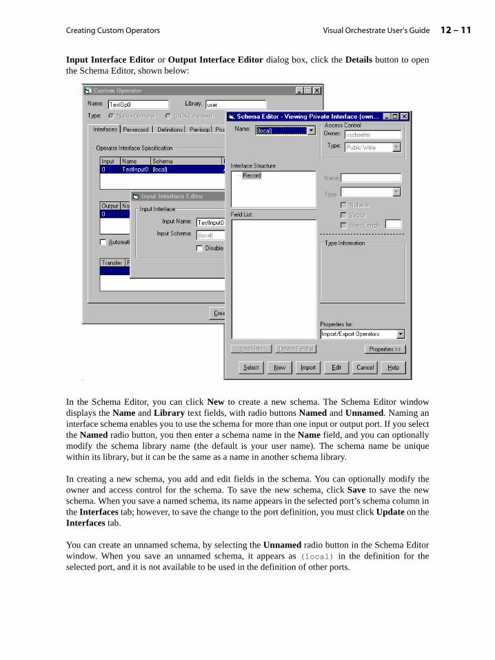
Creating Custom Operators 12 – 11Visual Orchestrate User’s Guide
olumn in
r
Input Interface Editor or Output Interface Editor dialog box, click the Details button to openthe Schema Editor, shown below:
In the Schema Editor, you can click New to create a new schema. The Schema Editor windowdisplays the Name and Library text fields, with radio buttons Named and Unnamed. Naming aninterface schema enables you to use the schema for more than one input or output port. If you selectthe Named radio button, you then enter a schema name in the Name field, and you can optionallymodify the schema library name (the default is your user name). The schema name be uniquewithin its library, but it can be the same as a name in another schema library.
In creating a new schema, you add and edit fields in the schema. You can optionally modify theowner and access control for the schema. To save the new schema, click Save to save the newschema. When you save a named schema, its name appears in the selected port’s schema cthe Interfaces tab; however, to save the change to the port definition, you must click Update on theInterfaces tab.
You can create an unnamed schema, by selecting the Unnamed radio button in the Schema Editowindow. When you save an unnamed schema, it appears as (local) in the definition for theselected port, and it is not available to be used in the definition of other ports.
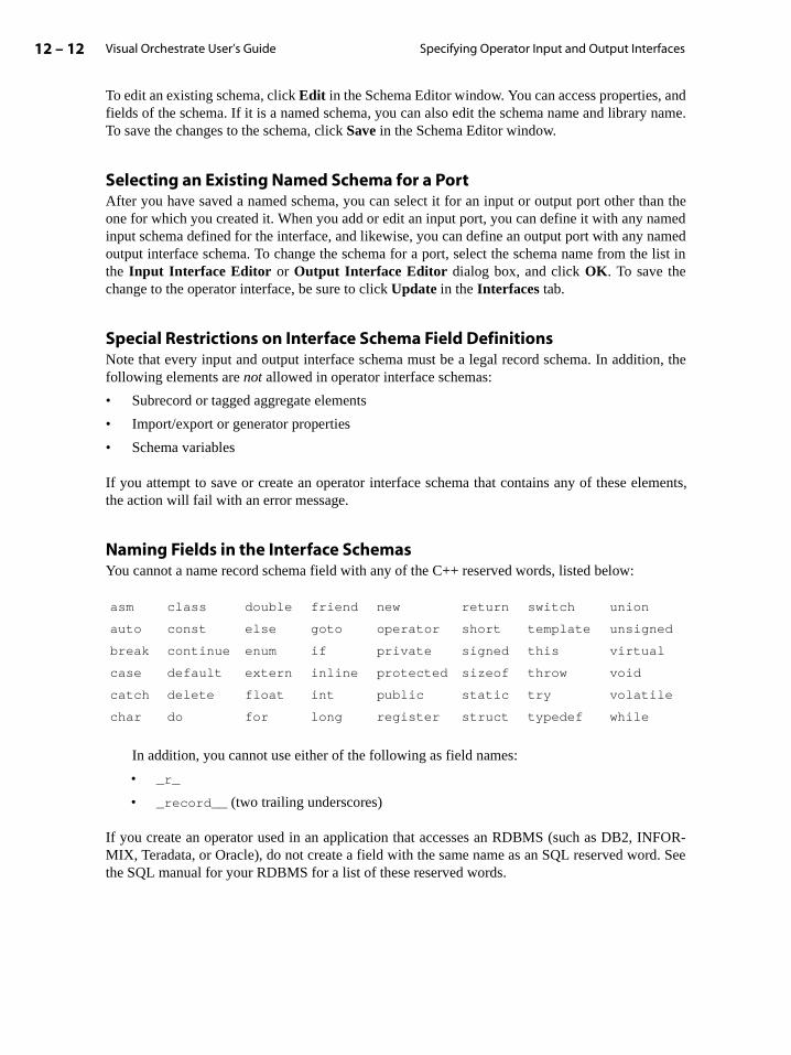
Visual Orchestrate User’s Guide12 – 12 Specifying Operator Input and Output Interfaces
lements,
NFOR-rd. See
To edit an existing schema, click Edit in the Schema Editor window. You can access properties, andfields of the schema. If it is a named schema, you can also edit the schema name and library name.To save the changes to the schema, click Save in the Schema Editor window.
Selecting an Existing Named Schema for a PortAfter you have saved a named schema, you can select it for an input or output port other than theone for which you created it. When you add or edit an input port, you can define it with any namedinput schema defined for the interface, and likewise, you can define an output port with any namedoutput interface schema. To change the schema for a port, select the schema name from the list inthe Input Interface Editor or Output Interface Editor dialog box, and click OK. To save thechange to the operator interface, be sure to click Update in the Interfaces tab.
Special Restrictions on Interface Schema Field DefinitionsNote that every input and output interface schema must be a legal record schema. In addition, thefollowing elements are not allowed in operator interface schemas:
• Subrecord or tagged aggregate elements
• Import/export or generator properties
• Schema variables
If you attempt to save or create an operator interface schema that contains any of these ethe action will fail with an error message.
Naming Fields in the Interface SchemasYou cannot a name record schema field with any of the C++ reserved words, listed below:
In addition, you cannot use either of the following as field names:
• _r_
• _record__ (two trailing underscores)
If you create an operator used in an application that accesses an RDBMS (such as DB2, IMIX, Teradata, or Oracle), do not create a field with the same name as an SQL reserved wothe SQL manual for your RDBMS for a list of these reserved words.
asm class double friend new return switch union
auto const else goto operator short template unsigned
break continue enum if private signed this virtual
case default extern inline protected sizeof throw void
catch delete float int public static try volatile
char do for long register struct typedef while
Creating Custom Operators 12 – 13Visual Orchestrate User’s Guide
a part of
of theort,
fers
, andsfer,g
it (at a and
xdelete
ldong allefault
ence iteeamed,index
Defining Transfers
You can define one or more transfers for your operator. As described in the section “HowGenerated Operator Processes Data” on page 12-3, Orchestrate performs a transfer asexecuting the code loop of the operator.
To define, modify, or delete a record transfer, open the Custom Operator dialog box, by clickingDefine Custom Operator or Edit Custom Operator in the Custom menu. On the Interfaces tab,the bottom list shows all transfers defined for your operator. The transfer column is the indextransfer (0-n-1), From Index is the index of the input port, To Index is the index of the output pand Properties is the automatic transfer setting (AUTO or NOAUTO) followed by the combine-transfersetting (COMBINE or SEPARATE). When you create an operator, by default there are no transdefined, and transfer definition is optional.
To define a transfer, click the Add button to the right of the transfer list to open the TransferEditor dialog box. From the From Input list, select the index of the input port for the transferfrom the To Output list, select the output port index. If you want to disable automatic trancheck the Disable Automatic Transfer box. If you want to prevent Orchestrate from combininthis transfer with others to the same output, check the Transfer Separately box. Click OK tocreate the transfer. The transfer then appears in the transfer list on the Interfaces tab.
To reorder the list of transfers, use the Up and Dn buttons for the list. Clicking Up exchanges theposition and index of the selected transfer with the position and index of the transfer above lower index number) in the list. Clicking Dn makes the exchange between the selected transferthe one below it.
To delete a transfer, select it in the transfer list and click Delete. Orchestrate decrements the indeof any transfers below it in the list. For example, if there are two transfers defined and you the first transfer in the list (index 0), the index of the second transfer is changed from 1 to 0.
Referencing Operator Interface Fields in Operator Code
In your Pre-loop, Post-loop, and Per-record code, you refer to schema components with the fiename, as defined in the input or output interface schema. If the field name is not unique aminterfaces, both input and output, for the operator, you must prefix the field name with the dor explicitly defined port name followed by a dot (.).
If the field name is not unique among all the operator’s interface schema, then you must referwith portname.field_name, where portname is either the name you have given the port (sthe section “Naming Input and Output Ports” on page 12-9) or, for a port that you have not nthe default name. For example, for a field price in your input schema for the third input port (2), which you have not explicitly named, you use the reference in2.price.
Visual Orchestrate User’s Guide12 – 14 Examples of Custom Operators
bbrevi-
Processing Fields According to Data Type and PropertiesTo let you process fields according to Orchestrate data type and properties, including nullable fieldsand vector fields, Orchestrate supplies functions that you can use in your code. These functions aredescribed in the section “Using Orchestrate Data Types in Your Operator” on page 12-20.
Examples of Custom Operators
This section describes how to define the following sample operators:
• “Example: Sum Operator” on page 12-15
• “Example: Sum Operator Using a Transfer” on page 12-16
• “Example: Operator That Recodes a Field” on page 12-17
• “Example: Adding a User-Settable Option to the Recoding Operator” on page 12-17
Convention for Property Settings in Examples
In all custom operator examples, the property settings for inputs, outputs, and transfers are aated, as follows:
• Inputs: Auto stands for automatic input (Disable automatic read is not checked), andNoauto stands for no automatic input (Disable automatic read is checked).
• Outputs: Auto stands for automatic output (Disable automatic write is not checked), andNoauto stands for no automatic output (Disable automatic write is checked).
• Transfers: Auto stands for automatic transfer (Disable automatic transfer is not checked),and Noauto stands for no automatic transfer (Disable automatic transfer is checked). Com-bine stands for combine transfer (Transfer separately (don’t combine with other transfersto the same output) is not checked), and Separate stands for separate transfer (Transferseparately... is checked).
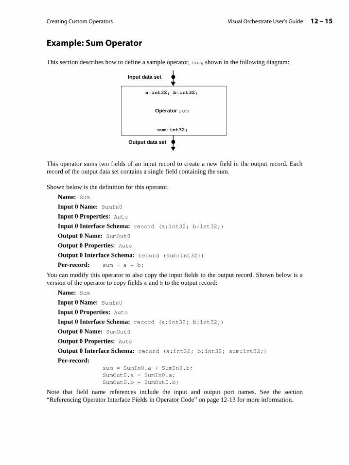
Creating Custom Operators 12 – 15Visual Orchestrate User’s Guide
n.
Example: Sum Operator
This section describes how to define a sample operator, sum, shown in the following diagram:
This operator sums two fields of an input record to create a new field in the output record. Eachrecord of the output data set contains a single field containing the sum.
Shown below is the definition for this operator.
Name: Sum
Input 0 Name: SumIn0
Input 0 Properties: Auto
Input 0 Interface Schema: record (a:int32; b:int32;)
Output 0 Name: SumOut0
Output 0 Properties: Auto
Output 0 Interface Schema: record (sum:int32;)
Per-record: sum = a + b;
You can modify this operator to also copy the input fields to the output record. Shown below is aversion of the operator to copy fields a and b to the output record:
Name: Sum
Input 0 Name: SumIn0
Input 0 Properties: Auto
Input 0 Interface Schema: record (a:int32; b:int32;)
Output 0 Name: SumOut0
Output 0 Properties: Auto
Output 0 Interface Schema: record (a:int32; b:int32; sum:int32;)
Per-record:sum = SumIn0.a + SumIn0.b;SumOut0.a = SumIn0.a;SumOut0.b = SumOut0.b;
Note that field name references include the input and output port names. See the section“Referencing Operator Interface Fields in Operator Code” on page 12-13 for more informatio
a:int32; b:int32;
Output data set
sum:int32;
Operator sum
Input data set

Visual Orchestrate User’s Guide12 – 16 Examples of Custom Operators
g
Example: Sum Operator Using a Transfer
This section contains a modified version of the sum operator described in the section “SpecifyinOperator Input and Output Interfaces” on page 12-8. This version of the sum operator performs atransfer from input to output, as shown below:
For a description of defining a transfer, see the section “Defining Transfers” on page 12-13.
Shown below is the definition for this operator.
Name: Sum
Input 0 Name: SumIn0
Input 0 Properties: Auto
Input 0 Interface Schema: record (a:int32; b:int32;)
Output 0 Name: SumOut0
Output 0 Properties: Auto
Output 0 Interface Schema: record (sum:int32;)
Transfer 0: Input From: 0; Output To: 0
Transfer 0 Properties: Auto, Combine
Per-record: sum = SumIn0.a + SumIn0.b;
a:int32; b:int32; inRec:*;
Output data set
sum:int32; outRec:*;
Operator sum
Input data set

Creating Custom Operators 12 – 17Visual Orchestrate User’s Guide
Example: Operator That Recodes a Field
This section describes how to define another sample operator, classifyPurchase, shown in thefollowing diagram:
In this example, operator ClassifyPurchase reads a record and transfers the entire input recordto the output data set. The operator also defines the field, code, for the output data set. The operatorassigns code the value 1 if the input field price is greater than or equal to 100, and 0 if price isbelow 100.
Shown below is the definition for this operator:
Name: ClassifyPurchase
Input 0 Name: PurchIn0
Input 0 Properties: Auto
Input 0 Interface Schema: record (price:dfloat;)
Output 0 Name: PurchOut0
Output 0 Properties: Auto
Output 0 Interface Schema: record (code:int8;)
Transfer 0: Input From: 0; Output To: 0
Transfer 0 Properties: Auto, Combine
Per-record:
if (PurchIn0.price >= 100) PurchOut0.code = 1;else PurchOut0.code = 0;
Example: Adding a User-Settable Option to the Recoding Operator
In the example above, operator ClassifyPurchase set the code field according to a setcondition: whether the price field has the cutoff value of 100 or greater. This example alters theClassifyPurchase operator, to define a parameter cutoff that operator users set. The operatorthen uses that cutoff to determine whether to set code to 1 or 0.
price:dfloat; inRec:*;
Output data set
code:int8; outRec:*;
classifyPurchase
Input data set
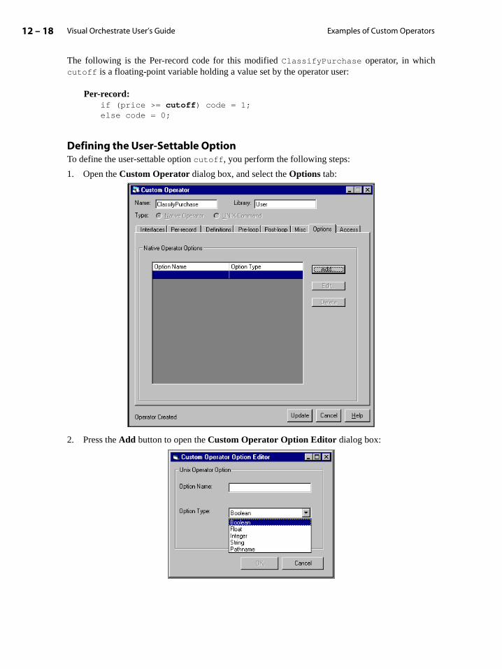
Visual Orchestrate User’s Guide12 – 18 Examples of Custom Operators
The following is the Per-record code for this modified ClassifyPurchase operator, in whichcutoff is a floating-point variable holding a value set by the operator user:
Per-record:if (price >= cutoff) code = 1;else code = 0;
Defining the User-Settable OptionTo define the user-settable option cutoff, you perform the following steps:
1. Open the Custom Operator dialog box, and select the Options tab:
2. Press the Add button to open the Custom Operator Option Editor dialog box:

Creating Custom Operators 12 – 19Visual Orchestrate User’s Guide
3. Specify the Option Name, which the operator user will select in the Option Editor dialogbox. For this example, you enter the name cutoff.
4. Select the Option Type from the pull-down list. As shown in the figure above, available datatypes are boolean, float, integer, string, and pathname. (An option of type pathnametakes a directory path, the validity of which must be determined by the operator.)
For this example, select type float.
5. Set the Option Name to cutoff.
6. Set the Option Type to float.
7. Click OK to close the Custom Operator Option Editor.
8. Click Update to rebuild operator ClassifyPurchase with the cutoff option.
How the Operator User Sets the OptionTo set the cutoff option for ClassifyPurchase, the operator user opens the OperatorProperties dialog box for ClassifyPurchase operator. The Add and Edit buttons open theOptions Editor dialog box, with which the user adds or edits an option setting. The user can alsouse the Delete button to delete a setting, and the Up and Down buttons to rearrange the order ofoption settings.
To add a setting for option cutoff, click Add to open the Option Editor. In that dialog box, enter avalue in the Value field. (Note that for a boolean option, the operator user simply selects ordeselects it.)
To add the setting to the operator without closing the Option Editor dialog box, click Add. Or, theclick OK to add the setting and close the Option Editor dialog box.

Visual Orchestrate User’s Guide12 – 20 Using Orchestrate Data Types in Your Operator
The following figure shows the Option Editor dialog box with the value 300.5 entered as acutoff option setting, and the Operator Properties dialog box after that option has been added.
To save the setting, in the Operator Properties dialog box, you must either click the Apply buttonto apply the setting to the operator, or click OK to apply the setting and close the OperatorProperties dialog box.
Using Orchestrate Data Types in Your Operator
This section describes how to code your operators to use all the Orchestrate data types, in the fol-lowing sections:
• “Using Numeric Fields” on page 12-21
• “Using Date, Time, and Timestamp Fields” on page 12-21
• “Using Decimal Fields” on page 12-23
• “Using String Fields” on page 12-24
• “Using Raw Fields” on page 12-25
• “Using Nullable Fields” on page 12-25
• “Using Vector Fields” on page 12-26
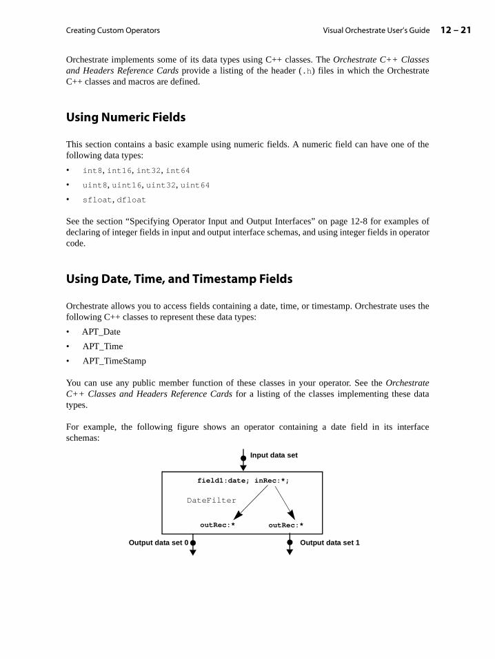
Creating Custom Operators 12 – 21Visual Orchestrate User’s Guide
les oferator
ses the
ta
rface
Orchestrate implements some of its data types using C++ classes. The Orchestrate C++ Classesand Headers Reference Cards provide a listing of the header (.h) files in which the OrchestrateC++ classes and macros are defined.
Using Numeric Fields
This section contains a basic example using numeric fields. A numeric field can have one of thefollowing data types:
• int8, int16, int32, int64
• uint8, uint16, uint32, uint64
• sfloat, dfloat
See the section “Specifying Operator Input and Output Interfaces” on page 12-8 for exampdeclaring of integer fields in input and output interface schemas, and using integer fields in opcode.
Using Date, Time, and Timestamp Fields
Orchestrate allows you to access fields containing a date, time, or timestamp. Orchestrate ufollowing C++ classes to represent these data types:
• APT_Date
• APT_Time
• APT_TimeStamp
You can use any public member function of these classes in your operator. See the OrchestrateC++ Classes and Headers Reference Cards for a listing of the classes implementing these datypes.
For example, the following figure shows an operator containing a date field in its inteschemas:
field1:date; inRec:*;
Input data set
Output data set 0
Output data set 1
DateFilter
outRec:* outRec:*
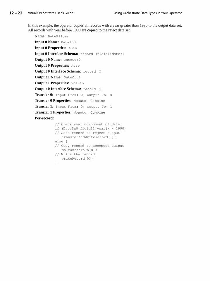
Visual Orchestrate User’s Guide12 – 22 Using Orchestrate Data Types in Your Operator
In this example, the operator copies all records with a year greater than 1990 to the output data set.All records with year before 1990 are copied to the reject data set.
Name: DateFilter
Input 0 Name: DateIn0
Input 0 Properties: Auto
Input 0 Interface Schema: record (field1:date;)
Output 0 Name: DateOut0
Output 0 Properties: Auto
Output 0 Interface Schema: record ()
Output 1 Name: DateOut1
Output 1 Properties: Noauto
Output 0 Interface Schema: record ()
Transfer 0: Input From: 0; Output To: 0
Transfer 0 Properties: Noauto, Combine
Transfer 1: Input From: 0; Output To: 1
Transfer 1 Properties: Noauto, Combine
Per-record:
// Check year component of date.if (DateIn0.field11.year() < 1990)// Send record to reject output
transferAndWriteRecord(1);else {// Copy record to accepted output
doTransfersTo(0);// Write the record.
writeRecord(0);}

Creating Custom Operators 12 – 23Visual Orchestrate User’s Guide
Using Decimal Fields
Orchestrate implements decimal fields using the C++ class APT_Decimal. The most commonfunctions of APT_Decimal that you may need to use in your operator are shown below:
You can use any public member function of these classes in your operator. See the OrchestrateC++ Classes and Headers Reference Cards to find the header file containing a completedescription of APT_Decimal.
For example, Orchestrate decimals do not provide arithmetic functions. In order to use a decimalwithin an arithmetic expression, you must first convert it to an integer or float, perform yourarithmetic operation, and convert it back to a decimal.
For example, the following operator adds two decimal fields and outputs a field containing thetotal:
Name: sum
Input 0 Name: SumIn0
Input 0 Properties: Auto
Input 0 Interface Schema: record (field1:decimal[6,2]; field2:decimal[6,2];)
Output 0 Name: SumOut0
Output 0 Properties: Auto
Output 0 Interface Schema: record (total:decimal[7,2];)
Per-record:
float var1 = SumIn0.field1.asDFloat();float var2 = SumIn0.field2.asDFloat();
float total_temp = var1 + var2;SumOut0.total.assignFromDFloat(total_temp);
Class APT_Decimal
assignFromDecimal()assignFromDFloat()assignFromInt32()assignFromString()asDFloat()asInteger()asString()compare()scale()stringLength()
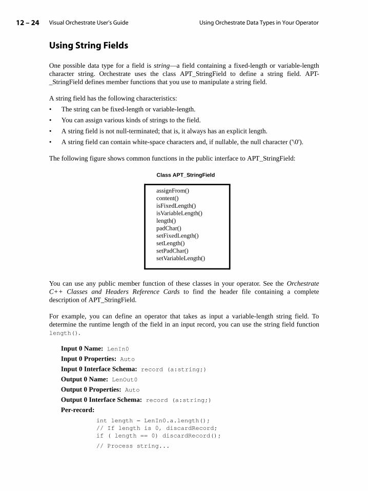
Visual Orchestrate User’s Guide12 – 24 Using Orchestrate Data Types in Your Operator
hAPT-
e
ld. Toction
Using String Fields
One possible data type for a field is string—a field containing a fixed-length or variable-lengtcharacter string. Orchestrate uses the class APT_StringField to define a string field. _StringField defines member functions that you use to manipulate a string field.
A string field has the following characteristics:
• The string can be fixed-length or variable-length.
• You can assign various kinds of strings to the field.
• A string field is not null-terminated; that is, it always has an explicit length.
• A string field can contain white-space characters and, if nullable, the null character ('\0').
The following figure shows common functions in the public interface to APT_StringField:
You can use any public member function of these classes in your operator. See the OrchestrateC++ Classes and Headers Reference Cards to find the header file containing a completdescription of APT_StringField.
For example, you can define an operator that takes as input a variable-length string fiedetermine the runtime length of the field in an input record, you can use the string field funlength().
Input 0 Name: LenIn0
Input 0 Properties: Auto
Input 0 Interface Schema: record (a:string;)
Output 0 Name: LenOut0
Output 0 Properties: Auto
Output 0 Interface Schema: record (a:string;)
Per-record:
int length = LenIn0.a.length();// If length is 0, discardRecord;if ( length == 0) discardRecord();
// Process string...
Class APT_StringField
assignFrom()content()isFixedLength()isVariableLength()length()padChar()setFixedLength()setLength()setPadChar()setVariableLength()
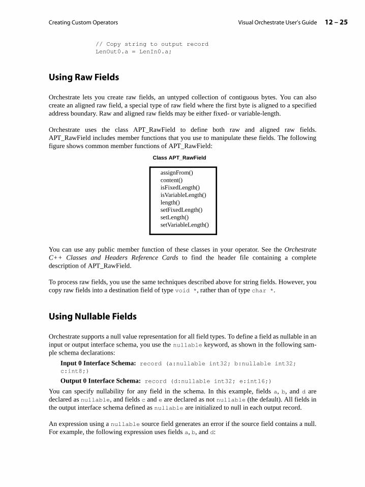
Creating Custom Operators 12 – 25Visual Orchestrate User’s Guide
// Copy string to output recordLenOut0.a = LenIn0.a;
Using Raw Fields
Orchestrate lets you create raw fields, an untyped collection of contiguous bytes. You can alsocreate an aligned raw field, a special type of raw field where the first byte is aligned to a specifiedaddress boundary. Raw and aligned raw fields may be either fixed- or variable-length.
Orchestrate uses the class APT_RawField to define both raw and aligned raw fields.APT_RawField includes member functions that you use to manipulate these fields. The followingfigure shows common member functions of APT_RawField:
You can use any public member function of these classes in your operator. See the OrchestrateC++ Classes and Headers Reference Cards to find the header file containing a completedescription of APT_RawField.
To process raw fields, you use the same techniques described above for string fields. However, youcopy raw fields into a destination field of type void *, rather than of type char *.
Using Nullable Fields
Orchestrate supports a null value representation for all field types. To define a field as nullable in aninput or output interface schema, you use the nullable keyword, as shown in the following sam-ple schema declarations:
Input 0 Interface Schema: record (a:nullable int32; b:nullable int32; c:int8;)
Output 0 Interface Schema: record (d:nullable int32; e:int16;)
You can specify nullability for any field in the schema. In this example, fields a, b, and d aredeclared as nullable, and fields c and e are declared as not nullable (the default). All fields inthe output interface schema defined as nullable are initialized to null in each output record.
An expression using a nullable source field generates an error if the source field contains a null.For example, the following expression uses fields a, b, and d:
Class APT_RawField
assignFrom()content()isFixedLength()isVariableLength()length()setFixedLength()setLength()setVariableLength()

Visual Orchestrate User’s Guide12 – 26 Using Orchestrate Data Types in Your Operator
hown
ele-vector
tor
ld
-
fied
fied
t
d = a / b;
In this case, both source fields (a and b) must not be null. If either field is null, the expressioncauses an error that terminates your application. Field d may contain a null, as it is the destination.The result of the expression is written to field d, replacing the null.
To process nullable fields, you can use the following functions:
• fieldName_null(): Returns the boolean value of true if fieldName contains a null andfalse if not.
• fieldName_setnull(): Sets an output field to null (input fields are read-only)
• fieldName_clearnull(): Sets an output field to non-null (input fields are read-only)
You can rewrite the example expression above to avoid an error caused by a nullable field, asshown below:
if (!a_null() && !b_null() )d = a / b;
Using Vector Fields
Orchestrate record schemas allow you to define vector fields (one-dimensional arrays). Sbelow is an example interface schema using vector fields:
Input 0 Interface Schema: record (a[10]:int8;)
Output 0 Interface Schema: record (total:int32;)
In this example, field a is a 10-element vector.
You can use the following functions with vector fields:
• fieldName[index]: Accesses the vector element at the specified index, where the firstment in the vector is at index 0. Vector elements in an input record are read-only, and elements in an output record are read/write.
• fieldName.vectorLength(): Returns, as an integer, the number of elements in the vec
• fieldName.setVectorLength(length): Sets the length of a variable-length vector fiein an output record (input fields are read-only)
• fieldName_null(index): Returns the boolean value true if the vector element at the specified index is null, and false if it is not
• fieldName_setnull(index): Sets the vector element in an output record at the speciindex to null (input fields are read-only)
• fieldName_clearnull(index): Sets the vector element in an output record at the speciindex to non-null (input fields are read-only)
The following code sums all the elements in the input vector a and stores the results in the outpufield total:
total = 0;
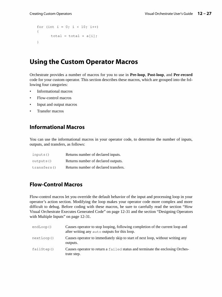
Creating Custom Operators 12 – 27Visual Orchestrate User’s Guide
inputs,
your more“Howerators
for (int i = 0; i < 10; i++){
total = total + a[i];
}
Using the Custom Operator Macros
Orchestrate provides a number of macros for you to use in Pre-loop, Post-loop, and Per-recordcode for your custom operator. This section describes these macros, which are grouped into the fol-lowing four categories:
• Informational macros
• Flow-control macros
• Input and output macros
• Transfer macros
Informational Macros
You can use the informational macros in your operator code, to determine the number of outputs, and transfers, as follows:
Flow-Control Macros
Flow-control macros let you override the default behavior of the input and processing loop inoperator’s action section. Modifying the loop makes your operator code more complex anddifficult to debug. Before coding with these macros, be sure to carefully read the section Visual Orchestrate Executes Generated Code” on page 12-31 and the section “Designing Opwith Multiple Inputs” on page 12-31.
inputs() Returns number of declared inputs.
outputs() Returns number of declared outputs.
transfers() Returns number of declared transfers.
endLoop() Causes operator to stop looping, following completion of the current loop and after writing any auto outputs for this loop.
nextLoop() Causes operator to immediately skip to start of next loop, without writing any outputs.
failStep() Causes operator to return a failed status and terminate the enclosing Orches-trate step.

Visual Orchestrate User’s Guide12 – 28 Using the Custom Operator Macros
nd
, you
on
For an example of using endLoop() in an $action section, see the section “Using Both auto anoauto Inputs” on page 12-34.
Input and Output Macros
The input and output macros let you control read, write, and transfer of individual records.
Each of the input and output macros listed below takes an argument, as follows:
• An input argument is the index (0-n) of the declared input, and an output argument is theindex (0-n) of the declared output. If you have defined a port name for an input or outputcan use portname.portid_ in place of the index.
• An index argument is the index (0-n) of the declared transfer.
For examples of using input and output macros, see the following:
• readRecord() in the section “Example Operator: reject” on page 12-30
• writeRecord() in several examples, including the section “Example Operator: reject”page 12-30 and “Example Operator: noauto” on page 12-34
• inputDone() in “Example Operator: noauto” on page 12-34
• discardRecord() and discardTransfer() in the example below
Example Using discardRecord() and discardTransfer(): Operator divideThe following example definition file is for operator divide, which calculates the quotient of twoinput fields. The operator checks to see if the divisor is zero. If it is, divide calls discardTrans-
readRecord(input) Immediately reads the next record from input, if there is one. If there is no record, the next call to inputDone() will return false.
writeRecord(output) Immediately writes a record to output.
inputDone(input) Returns true if the last call to readRecord() for the specified input failed to read a new record, because the input has no more records.
holdRecord(input) Causes auto input to be suspended for the current record, so that the operator does not automatically read a new record at the start of the next loop. If auto is not set for the input, holdRecord() has no effect.
discardRecord(output) Causes auto output to be suspended for the current record, so that the operator does not output the record at the end of the cur-rent loop. If auto is not set for the output, discardRecord() has no effect.
discardTransfer(index) Causes auto transfer to be suspended, so that the operator does not perform the transfer at the end of the current loop. If auto is not set for the transfer, discardTransfer() has no effect.
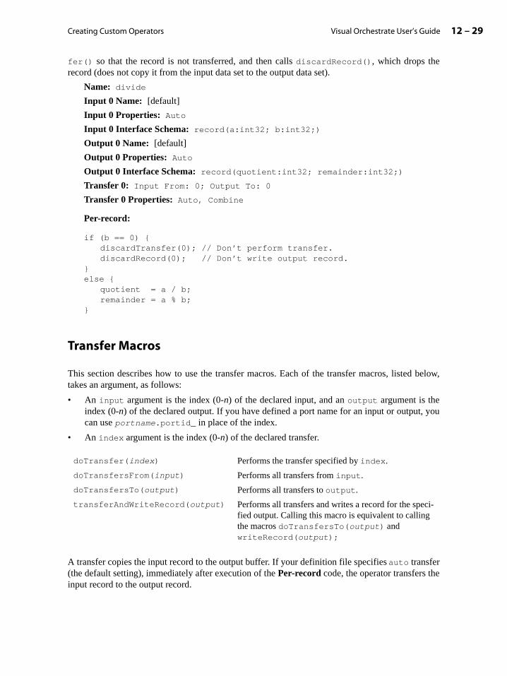
Creating Custom Operators 12 – 29Visual Orchestrate User’s Guide
, you
e
fer() so that the record is not transferred, and then calls discardRecord(), which drops therecord (does not copy it from the input data set to the output data set).
Name: divide
Input 0 Name: [default]
Input 0 Properties: Auto
Input 0 Interface Schema: record(a:int32; b:int32;)
Output 0 Name: [default]
Output 0 Properties: Auto
Output 0 Interface Schema: record(quotient:int32; remainder:int32;)
Transfer 0: Input From: 0; Output To: 0
Transfer 0 Properties: Auto, Combine
Per-record:
if (b == 0) {discardTransfer(0); // Don’t perform transfer.discardRecord(0); // Don’t write output record.
}else {
quotient = a / b;remainder = a % b;
}
Transfer Macros
This section describes how to use the transfer macros. Each of the transfer macros, listed below,takes an argument, as follows:
• An input argument is the index (0-n) of the declared input, and an output argument is theindex (0-n) of the declared output. If you have defined a port name for an input or outputcan use portname.portid_ in place of the index.
• An index argument is the index (0-n) of the declared transfer.
A transfer copies the input record to the output buffer. If your definition file specifies auto transfer(the default setting), immediately after execution of the Per-record code, the operator transfers thinput record to the output record.
doTransfer(index) Performs the transfer specified by index.
doTransfersFrom(input) Performs all transfers from input.
doTransfersTo(output) Performs all transfers to output.
transferAndWriteRecord(output) Performs all transfers and writes a record for the speci-fied output. Calling this macro is equivalent to calling the macros doTransfersTo(output) and writeRecord(output);
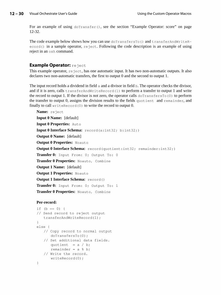
Visual Orchestrate User’s Guide12 – 30 Using the Custom Operator Macros
ge
ng
also
,e
For an example of using doTransfer(), see the section “Example Operator: score” on pa12-32.
The code example below shows how you can use doTransfersTo() and transferAndWriteR-ecord() in a sample operator, reject. Following the code description is an example of usireject in an osh command.
Example Operator: rejectThis example operator, reject, has one automatic input. It has two non-automatic outputs. It declares two non-automatic transfers, the first to output 0 and the second to output 1.
The input record holds a dividend in field a and a divisor in field b. The operator checks the divisorand if it is zero, calls transferAndWriteRecord(1) to perform a transfer to output 1 and writthe record to output 1. If the divisor is not zero, the operator calls doTransfersTo(0) to performthe transfer to output 0, assigns the division results to the fields quotient and remainder, andfinally to call writeRecord(0) to write the record to output 0.
Name: reject
Input 0 Name: [default]
Input 0 Properties: Auto
Input 0 Interface Schema: record(a:int32; b:int32;)
Output 0 Name: [default]
Output 0 Properties: Noauto
Output 0 Interface Schema: record(quotient:int32; remainder:int32;)
Transfer 0: Input From: 0; Output To: 0
Transfer 0 Properties: Noauto, Combine
Output 1 Name: [default]
Output 1 Properties: Noauto
Output 1 Interface Schema: record()
Transfer 0: Input From: 0; Output To: 1
Transfer 0 Properties: Noauto, Combine
Per-record:
if (b == 0) {// Send record to reject output
transferAndWriteRecord(1);}else {
// Copy record to normal outputdoTransfersTo(0);
// Set additional data fields.quotient = a / b;remainder = a % b;
// Write the record.writeRecord(0);
}

Creating Custom Operators 12 – 31Visual Orchestrate User’s Guide
ns-
op
ra-
of mul-gestedinputs.
How Visual Orchestrate Executes Generated Code
This section describes how Visual Orchestrate executes the code generated from your customoperator definition. If you are writing simple operators and your code uses only the default,automatic I/O handling, you do not need to be concerned with the details of this section. If you arewriting more complex operators with non-default I/O handling, these details can be helpful.
Visual Orchestrate executes your custom operator code, as follows:
1. Handles any definitions that you have entered in the Definitions tab of the Custom Operatordialog box.
2. If you have entered any code in the Pre-loop section, executes it.
3. Loops repeatedly until either all inputs have run out of records, or the Per-record code hasexplicitly invoked endLoop(). In the loop, performs the following steps:
a. Reads one record for each input, except where any of the following is true:
• The input has no more records left.
• The input has been declared with noauto.
• The holdRecord() macro was called for the input last time around the loop.
b. Executes the Per-record code, which can explicitly read and write records, perform trafers, and invoke loop-control macros such as endLoop().
c. Performs each specified transfer, except where any of the following is true:
• The input of the transfer has no more records.
• The transfer has been declared with noauto.
• The discardTransfer() macro was called for the transfer during the current loiteration.
d. Writes one record for each output, except where any of the following is true:
• The output was declared with noauto.
• The discardRecord() macro was called for the output during the current loop itetion.
4. If you have specified Post-loop code, executes it.
5. Returns a status value, which is one of the following:
APT_StatusOk (value 0). The default.
APT_StatusFailed (value 1). Returned only if your code has invoked failStep().
Designing Operators with Multiple Inputs
Orchestrate supports creation of operators that perform complex data handling, through use tiple inputs and outputs, flow control, and transfers. This section describes some sugapproaches for designing operators that successfully handle the challenge of using multiple
Visual Orchestrate User’s Guide12 – 32 Designing Operators with Multiple Inputs
t.
mores per-rator to
eeded
eededing theecords
ed fea-ultiple
cord on any
s on
every
ands score
Note: Whenever possible, use the standard, automatic read, write, and record transfer featuresdescribed in this chapter. In using non-automatic inputs, outputs, or record transfers in your opera-tor definition, you introduce complexity and a greater possibility of programming errors.
Requirements for Coding for Multiple Inputs
To use multiple inputs effectively, your operator code needs to meet the following two require-ments:
• Perform a read of a record’s fields only when the record is available on the specified inpu
Make sure that your operator code will not attempt to read a field from an input with no records. It also must not attempt to read a field on a non-automatic input before it haformed a read on that input. Failure to prevent either of these situations causes the opefail with an error message similar to the following:
isUsable() false on accessor interfacing to field "fieldname"
• Terminate the reading of records from each input immediately after (but not before) all nrecords have been read from it.
If you declare any inputs as non-automatic, your operator must determine when all nrecords have been read from all inputs, and at that point to terminate the operator by callendLoop() macro. Remember that the operator continues to loop as long as there are rremaining on any of its inputs.
Strategies for Using Multiple Inputs and Outputs
In general, the best approach to coding for multiple inputs is the simplest, using the automattures as much as possible. Below are three simple strategies for designing an operator with minputs:
Using Automatic Read for All InputsIn this approach to multiple inputs, your definition file defines all inputs as automatic, so all rereads are handled automatically. You code your operator so that each time it accesses a fieldinput, it first invokes the inputDone() macro to determine whether there are any more recordthe input.
Note that this strategy is appropriate only if you want your operator to read a record from input, every time around the loop.
Example Operator: scoreThis example operator, score, uses two automatic inputs. It also uses non-automatic outputsrecord transfers, so that it writes record only when the operator code has determined that itfield has the highest value among all records of that type.

Creating Custom Operators 12 – 33Visual Orchestrate User’s Guide
Name: score
Input 0 Name: [default]
Input 0 Properties: Auto
Input 0 Interface Schema: record(type:int32; score:int32;)
Output 0 Name: [default]
Output 0 Properties: Noauto
Output 0 Interface Schema: record ()
Transfer 0: Input From: 0; Output To: 0
Transfer 0 Properties: Noauto, Combine
Pre-loop:
int current_type = -1;
int current_score = -1;
Per-record:
// Operator score uses the output record as a buffer for// the highest-scoring record of each type processed.
// Assumptions about input:// The input data is hash-partitioned on the type field.// All records are guaranteed to have a score value not equal to -1.
// If the input has passed the final record of a type,// output the buffered high-scoring record for that type,// and reset the score.
if (type != current_type && current_type != -1) {// write highest scored record from previous group.writeRecord(0);// start tracking new typecurrent_type = type;current_score = -1;
}
// If current record beats previous score, transfer it// to the output buffer, but don’t write it yet.if (score > current_score) {
doTransfersTo(0);current_score = score;current_type = type;
}
$post
// If there’s a remaining record, write it to output.if (current_type != -1) {
writeRecord(0);}

Visual Orchestrate User’s Guide12 – 34 Designing Operators with Multiple Inputs
perator:
l
s,
isorms allerges
hism
Using Both auto and noauto InputsYour definition file declares one automatic input (or possibly more than one), and the remaininginputs as non-automatic. You code your operator to let the processing of records from the automaticinput drive the handling of the other inputs. Each time around the loop, your operator calls input-Done() on the automatic input. When the automatic input has no more records, your code callsexitLoop() to complete the operator action.
For an example of an operator that uses this coding strategy, see the section “Example Oreject” on page 12-30.
Using noauto for All InputsYour definition file declares all inputs as non-automatic (noauto), so your code must perform alrecord reads. You declare a Pre-loop section, which you code to call readRecord() once for eachinput. You code the Per-record section to invoke inputDone() for every input, on every iterationof the loop, to determine whether it obtained a record on the most recent readRecord(). If it did,process the record, and then call readRecord() on that input. When all inputs run out of recordthe operator automatically exits the Per-record section.
Example Operator: noautoThe following example operator, noauto, illustrates this strategy for reading multiple inputs. Thexample uses non-automatic inputs, outputs, and transfers, so that the operator code perfreading and writing explicitly. This operator takes three inputs, with similar schemas, and mthem into a single output. It also has a separate output for records that have been rejected.
Unlike the Orchestrate merge operator, this operator filters and modifies some of the input. Toperator modifies the id field to reflect the input source (0, 1, or 2). It also filters records froinputs 1 and 2, according to the values of fields a and b.
Name: noauto
Input 0 Name: [default]
Input 0 Properties: Noauto
Input 0 Interface Schema: record (id:int32;)
Input 1 Name: [default]
Input 1 Properties: Noauto
Input 1 Interface Schema: record (id:int32; a:int32;)
Input 2 Name: [default]
Input 2 Properties: Noauto
Input 2 Interface Schema: record (id:int32; a:int32; b:int32;)
Output 0 Name: [default]
Output 0 Properties: Noauto
Output 0 Interface Schema: record (id:int32;)
Output 1 Name: [default]
Output 1 Properties: Noauto
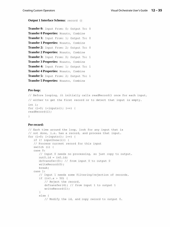
Creating Custom Operators 12 – 35Visual Orchestrate User’s Guide
Output 1 Interface Schema: record ()
Transfer 0: Input From: 0; Output To: 0
Transfer 0 Properties: Noauto, Combine
Transfer 1: Input From: 1; Output To: 0
Transfer 1 Properties: Noauto, Combine
Transfer 2: Input From: 2; Output To: 0
Transfer 2 Properties: Noauto, Combine
Transfer 3: Input From: 0; Output To: 1
Transfer 3 Properties: Noauto, Combine
Transfer 4: Input From: 1; Output To: 1
Transfer 4 Properties: Noauto, Combine
Transfer 5: Input From: 2; Output To: 1
Transfer 5 Properties: Noauto, Combine
Pre-loop:
// Before looping, it initially calls readRecord() once for each input,
// either to get the first record or to detect that input is empty.
int i;for (i=0; i<inputs(); i++) {readRecord(i);
}
Per-record:
// Each time around the loop, look for any input that is // not done, i.e. has a record, and process that input.for (i=0; i<inputs(); i++) {
if (! inputDone(i)) {// Process current record for this inputswitch (i) {case 0:
// Input 0 needs no processing, so just copy to output.out0.id = in0.id;doTransfer(0); // from input 0 to output 0writeRecord(0);break;
case 1:// Input 1 needs some filtering/rejection of records.if (in1.a > 50) {
// Reject the record.doTransfer(4); // from input 1 to output 1writeRecord(1);
}else {
// Modify the id, and copy record to output 0.

Visual Orchestrate User’s Guide12 – 36 Designing Operators with Multiple Inputs
out0.id = in1.id + 10000;doTransfer(1); // from input 1 to output 0writeRecord(0);
}break;
case 2:// Input 2 needs different filtering/rejection.if (in2.a > 50 || in2.b > 50) {
// reject the recorddoTransfer(5); // from input 2 to output 1writeRecord(1);
}else { // Modify the id appropriately.
if (in2.a > in2.b)out0.id = in2.id + 20000;
elseout0.id = in2.id + 30000;
// Copy the record to output 0.doTransfer(2); // from input 2 to output 0writeRecord(0);
}break;
}
// Get next record for this input (or detect end of input).readRecord(i);
}}
// When all inputs are exhausted, operator automatically terminates.
13 – 1Visual Orchestrate User’s Guide
ges:
it can
hes-
13: Creating UNIX Operators
Orchestrate lets you use UNIX programs and commands in your Orchestrate application,just as you use predefined Orchestrate operators. This capability lets you run existing UNIXprograms in parallel within an Orchestrate application, without having to rewrite them.
To execute your existing UNIX programs in Orchestrate, you create UNIX command opera-tors. UNIX command operators execute your UNIX application in parallel or sequentially aspart of an Orchestrate step. You can use UNIX command operators in the same step that youuse Orchestrate operators.
This chapter describes how to create UNIX command operators. It describes how to handlevarious kinds of operator inputs and outputs and how to define operators that accept user-settable options. The final section of this chapter describes optimizations that Orchestrateperforms with UNIX command operators.
This chapter contains the following sections:
• “Introduction to UNIX Command Operators” on page 13-1
• “Handling Operator Inputs and Outputs” on page 13-7
• “Passing Arguments to and Configuring UNIX Commands” on page 13-22
• “Handling Command Exit Codes” on page 13-35
• “How Orchestrate Optimizes Command Operators” on page 13-36
Introduction to UNIX Command Operators
The Orchestrate framework includes many operators, which you use to perform basic dataprocessing tasks such as copy, sample, and merge. Orchestrate also lets you create custom operatorsfrom existing or new code, to run in parallel in your Orchestrate application. This chapter describeshow to use Visual Orchestrate to create custom operators from existing UNIX shell commands.UNIX shell commands can be invoked from a UNIX shell prompt, and include UNIX built-incommands such as grep, UNIX utilities such as SyncSort, and your own UNIX applications. (Youcan also create custom operators from your own code in C or C++; see the chapter “CreatingCustom Operators”.)
Executing an existing UNIX application as a UNIX command operator has two main advanta
1. Orchestrate’s parallel execution improves the performance of your UNIX application, as process larger amounts of data than it can in sequential execution.
2. You can use your existing UNIX application, without any reimplementation, in your Orctrate application,.
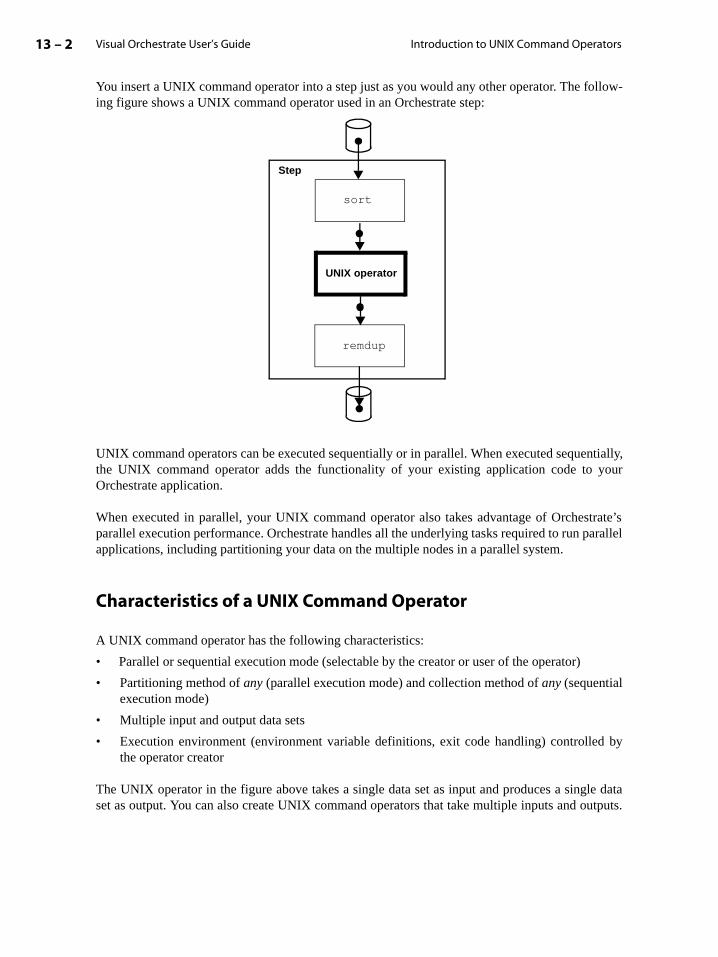
Visual Orchestrate User’s Guide13 – 2 Introduction to UNIX Command Operators
trate’sarallel
d by
le datautputs.
You insert a UNIX command operator into a step just as you would any other operator. The follow-ing figure shows a UNIX command operator used in an Orchestrate step:
UNIX command operators can be executed sequentially or in parallel. When executed sequentially,the UNIX command operator adds the functionality of your existing application code to yourOrchestrate application.
When executed in parallel, your UNIX command operator also takes advantage of Orchesparallel execution performance. Orchestrate handles all the underlying tasks required to run papplications, including partitioning your data on the multiple nodes in a parallel system.
Characteristics of a UNIX Command Operator
A UNIX command operator has the following characteristics:
• Parallel or sequential execution mode (selectable by the creator or user of the operator)
• Partitioning method of any (parallel execution mode) and collection method of any (sequentialexecution mode)
• Multiple input and output data sets
• Execution environment (environment variable definitions, exit code handling) controllethe operator creator
The UNIX operator in the figure above takes a single data set as input and produces a singset as output. You can also create UNIX command operators that take multiple inputs and o
UNIX operator
Step
sort
remdup
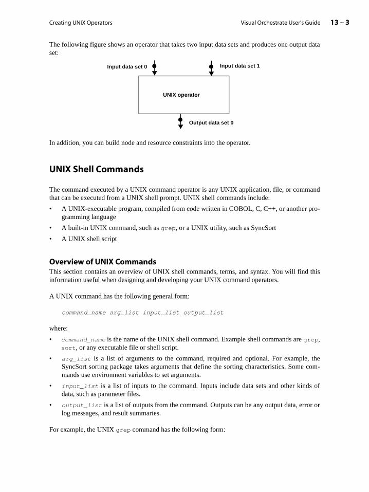
Creating UNIX Operators 13 – 3Visual Orchestrate User’s Guide
pro-
this
, thee com-
ds of
or or
The following figure shows an operator that takes two input data sets and produces one output dataset:
In addition, you can build node and resource constraints into the operator.
UNIX Shell Commands
The command executed by a UNIX command operator is any UNIX application, file, or commandthat can be executed from a UNIX shell prompt. UNIX shell commands include:
• A UNIX-executable program, compiled from code written in COBOL, C, C++, or another gramming language
• A built-in UNIX command, such as grep, or a UNIX utility, such as SyncSort
• A UNIX shell script
Overview of UNIX CommandsThis section contains an overview of UNIX shell commands, terms, and syntax. You will findinformation useful when designing and developing your UNIX command operators.
A UNIX command has the following general form:
command_name arg_list input_list output_list
where:
• command_name is the name of the UNIX shell command. Example shell commands are grep,sort, or any executable file or shell script.
• arg_list is a list of arguments to the command, required and optional. For exampleSyncSort sorting package takes arguments that define the sorting characteristics. Sommands use environment variables to set arguments.
• input_list is a list of inputs to the command. Inputs include data sets and other kindata, such as parameter files.
• output_list is a list of outputs from the command. Outputs can be any output data, errlog messages, and result summaries.
For example, the UNIX grep command has the following form:
UNIX operator
Input data set 0 Input data set 1
Output data set 0
Visual Orchestrate User’s Guide13 – 4 Introduction to UNIX Command Operators
put.
put.
r.
manditsUNIX
can be are
grep [ -bchilnsvw ] limited-regular-expression [ filename ... ]
The grep command searches one or more input files for a pattern and outputs all lines that containthat pattern. If the command line specifies no input files, grep takes its input from the standardinput. By default, grep writes output to standard output.
UNIX commands take their input from one of the following sources:
• Standard input (stdin): Each UNIX command can have a single connection to standard inBy default, standard input is the keyboard.
• Files: Data files specified as arguments to the UNIX command.
UNIX commands write their output to one of the following:
• Standard output (stdout): A UNIX command can have a single connection to standard outBy default, standard output is the screen.
• Standard error (stderr): A UNIX command can have a single connection to standard erro
• Files: Data files are specified as arguments to the UNIX command.
For example, the following command line causes grep to reads its input from the file custs.txtand to write all lines of the file containing the string MA to standard output (the screen):
grep MA custs.txt
You can also use standard input and output to connect UNIX commands, as shown below:
cat options | grep options
where options are any arguments passed to the commands. The pipe symbol (|) indicates aconnection between two UNIX commands. In this example, cat writes its output to its standardoutput, and grep reads its input from cat on the standard input of grep.
UNIX Commands Must Be Pipe-SafeOrchestrate imposes one requirement on the UNIX command executed by a UNIX comoperator: the command must be pipe-safe. To be pipe-safe, a UNIX command always reads input sequentially, from beginning to end. More specifically, the command does not use the random-access command, seek, on any of its inputs.
UNIX commands that are pipe-safe can be connected with a UNIX pipe, as shown below:
$ cat options | grep options | sort options
UNIX commands that read from standard input or write to standard output are pipe-safe andincluded in a UNIX command operator. UNIX commands that read from or write to filesusually pipe-safe.

Creating UNIX Operators 13 – 5Visual Orchestrate User’s Guide
a filemand
ile.
a fileads as
Execution of a UNIX Command Operator
A UNIX command operator takes as input a data set containing data in the Orchestrate recordformat. The embedded shell command then processes Orchestrate records one by one. The left-hand side of the figure below shows an Orchestrate application step that uses a UNIX commandoperator, and the right-hand side shows an expanded representation of the operator as it processesdata.
In the figure above, the UNIX command operator performs both an export and an import operation.It performs the export to convert the input data set to the data format required by the UNIXcommand, and it performs the import to convert the output of the UNIX command to theOrchestrate data set format. The UNIX command, executed by the command operator, receives andprocesses data normally from either standard input or a file.
The following procedure summarizes the action of the UNIX command operator:
1. To convert input records to a format compatible with the UNIX command, Orchestrate exportsthe data set records.
You control how the output of the export operator is delivered to the input of the UNIX com-mand: either through the command’s standard input or through a file name. If you usename, rather than writing the data to disk Orchestrate creates a UNIX pipe that the comreads in the same way that it reads a file.
2. The UNIX command processes its input and writes its output to standard output or to a f
3. The result of the UNIX command is sent to the import operator, which converts it to anOrchestrate data set.
You control how the output of the UNIX command is delivered to the input of the import
operator: either through the command’s standard output or through a file name. If you usename, rather than writing the data to disk Orchestrate creates a UNIX pipe that import reit reads a file.
UNIX operator
Operator
Step export
import
UNIX command
file or stdin
file or stdout
1
2
3

Visual Orchestrate User’s Guide13 – 6 Introduction to UNIX Command Operators
ASCII
trings
new-ecords
Forerator
andestrate
enerateduts and
g exe-
stead, the
For UNIX command operators with multiple inputs, Orchestrate separately exports data for eachinput. For each output of the operator, Orchestrate separate imports data for each output.
Default Properties for Operator Export and Import By default, a UNIX command operator uses the following export properties:
• A new-line character delimits the end of each record.
• An ASCII space (0x20) separates all fields.
• The record uses a text representation for all data including numeric data (an unpackedrepresentation with one byte per digit).
This export format corresponds to the record schema:
record()
With this default export format, the embedded UNIX command receives its input as text sterminated by new-line characters.
By default, a UNIX command operator imports data by creating one output record from eachline delimited text string that is output by the embedded UNIX shell command. Each output rcontains a single, variable-length, string field named rec. This default import format correspondto the record schema:
record(rec:string;)
Many UNIX command operators require a non-default schema for import or export.information on specifying the import and export schemas, see the section “Handling OpInputs and Outputs” on page 13-7 for more information.
Orchestrate can perform several kinds of performance optimization on your UNIX commoperators, based on their import and export record schemas. See the section “How OrchOptimizes Command Operators” on page 13-36 for more information.
Handling Other Input/Output TypesThe example UNIX command operators shown above have taken data sets as inputs and gdata sets as outputs. However, many UNIX commands operators handle other types of inpoutputs, including;
• Input parameter files used to configure the command
• Environment variables specifying configuration information
• Output message and error logs containing information generated by the command durincution
• Output files containing results or result summaries
Inputs and outputs of these types do not have to be represented by Orchestrate data sets. InUNIX command can read directly from these inputs or write directly to these outputs.

Creating UNIX Operators 13 – 7Visual Orchestrate User’s Guide
more
ver, ifnce of section
accessand on allles to
ariouse fol-
s byhe end,
n by anibute it retrieve
d out-ection
For example, when a step passes the name of a parameter file as an argument to a UNIX commandoperator, the UNIX command directly reads the parameter file for its configuration information.See the section “Handling Configuration and Parameter Input Files” on page 13-25 for information.
Likewise, an embedded UNIX command can write directly to message and error logs. Howeyou are running the UNIX command operator in parallel, you must make sure that each instathe operator writes to a separate file, as defined by a file name or a path name. See the“Handling Command Exit Codes” on page 13-35.
If an embedded UNIX command uses environment variables, the command must be able tothe environment variable to obtain runtime configuration information. If the UNIX commoperator runs in parallel, you must make sure that the environment variable is set correctlyprocessing nodes executing the operator. See the section “Using Environment VariabConfigure UNIX Commands” on page 13-26 for more information.
Handling Operator Inputs and Outputs
One of the most important aspects of creating UNIX command operators is handling the vkinds of inputs and outputs that UNIX commands can require. UNIX commands can take thlowing kinds of inputs:
• Data (from a file, or standard input)
• Command-line arguments
• Parameter files
UNIX commands can write the following kinds of output:
• Data (to a file, standard output, or standard error)
• Messages (to a file, standard output, or standard error)
• Results (to a file or standard output)
Orchestrate uses a data-flow programming environment, in which you define applicationconnecting operators using data sets. In this way, data flows from the beginning of a step to tas each operator processes a stream of input records to create an output record stream.
You use Orchestrate data sets to input data to an operator and to hold the output data writteoperator. By using data sets, you let Orchestrate handle the partitioning of your data to distrto the processing nodes executing a parallel operator. In addition, data sets let you store andyour data in parallel.
For command operators that invoke UNIX commands that require other types of inputs anputs, you must decide how your operator will handle those inputs and outputs. This s
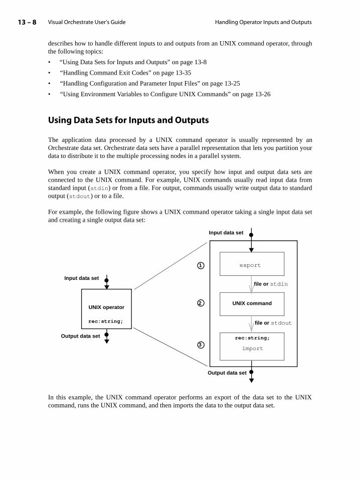
Visual Orchestrate User’s Guide13 – 8 Handling Operator Inputs and Outputs
by antion your
ts are fromard
ta set
UNIX
describes how to handle different inputs to and outputs from an UNIX command operator, throughthe following topics:
• “Using Data Sets for Inputs and Outputs” on page 13-8
• “Handling Command Exit Codes” on page 13-35
• “Handling Configuration and Parameter Input Files” on page 13-25
• “Using Environment Variables to Configure UNIX Commands” on page 13-26
Using Data Sets for Inputs and Outputs
The application data processed by a UNIX command operator is usually represented Orchestrate data set. Orchestrate data sets have a parallel representation that lets you partidata to distribute it to the multiple processing nodes in a parallel system.
When you create a UNIX command operator, you specify how input and output data seconnected to the UNIX command. For example, UNIX commands usually read input datastandard input (stdin) or from a file. For output, commands usually write output data to standoutput (stdout) or to a file.
For example, the following figure shows a UNIX command operator taking a single input daand creating a single output data set:
In this example, the UNIX command operator performs an export of the data set to the command, runs the UNIX command, and then imports the data to the output data set.
export
UNIX commandUNIX operator
Input data set
Output data set
Input data set
Output data set
file or stdin
file or stdout
1
2
3
rec:string;
import
rec:string;
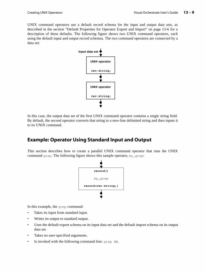
Creating UNIX Operators 13 – 9Visual Orchestrate User’s Guide
for aeachted by a
field.puts it
UNIX
output
UNIX command operators use a default record schema for the input and output data sets, asdescribed in the section “Default Properties for Operator Export and Import” on page 13-6description of these defaults. The following figure shows two UNIX command operators, using the default input and output record schemas. The two command operators are connecdata set:
In this case, the output data set of the first UNIX command operator contains a single stringBy default, the second operator converts that string to a new-line delimited string and then into its UNIX command.
Example: Operator Using Standard Input and Output
This section describes how to create a parallel UNIX command operator that runs the command grep. The following figure shows this sample operator, my_grep:
In this example, the grep command:
• Takes its input from standard input.
• Writes its output to standard output.
• Uses the default export schema on its input data set and the default import schema on itsdata set.
• Takes no user-specified arguments.
• Is invoked with the following command line: grep MA.
UNIX operator
rec:string;
UNIX operator
rec:string;
Input data set
my_grep
record(rec:string;)
record()

Visual Orchestrate User’s Guide13 – 10 Handling Operator Inputs and Outputs
This command line defines a simple filter operator that outputs only the records containing thestring MA.
To create a UNIX command operator, perform the following steps:
1. Choose Custom -> Define Custom Operator from the Orchestrate menu. This commandopens the following dialog box:
This dialog box allows you to create a new operator (default), or to copy the definition of anexisting operator and edit that definition to create a new operator. You create a New Operatorin this example.
2. Click OK to open the Custom Operator dialog box.
3. Click the UNIX Command button, as shown in the figure below:UNIX Command
Command echo

Creating UNIX Operators 13 – 11Visual Orchestrate User’s Guide
Oper-
p.
and
desccess-
4. Specify the Name of the operator: my_grep.
5. Specify the Library name for the operator: User.
6. Specify the Command: grep MA.
As you enter the command, you see it echoed in the Sample Command Line area of the dia-log box. This area shows how the UNIX application will be invoked by the operator.
In the Command Line Argument Order area, the list of operator arguments is empty. For adescription of adding and using command operator arguments, see the section “Handlingator Inputs and Outputs” on page 13-7.
7. Specify the Operator Type as Parallel.
You can specify Parallel, Sequential, or Operator Default (default). Operator Defaultallows the operator user to set the execution mode when inserting the operator into a ste
8. Choose the Exit & Environment tab:
This dialog box lets you define the environment variables used by the UNIX commandcontrol how Orchestrate handles exit codes returned by the command.
In the Command Exit Code Handling area, specify how Orchestrate interprets the exit coreturned from the UNIX command. By default, Orchestrate treats an exit code of 0 as suful and all others as errors.
For this operator, specify:
Success Codes = 0 and 1: Exit codes 0 and 1 indicate success; all others are errors.

Visual Orchestrate User’s Guide13 – 12 Handling Operator Inputs and Outputs
ars in
erator
use a
default output,descrip-
You must set 1 as a valid exit code because grep returns both 0 and 1 to indicate success.An exit code of 0 means grep found the search string; an exit code of 1 means it did not.
See the section “Handling Command Exit Codes” on page 13-35 for more information.
9. Enter 1 in the Success Code field.
10. Press the Add button to add 1 as a success code.
11. Use the New Operator dialog box buttons to do one of the following:
• Save the information about the operator, but do not create it. A saved operator appethe Server View area in parentheses, to indicate that it has not yet been created.
• Create the operator so that you can use it in your application. You must create the opbefore an operator user can use it.
• Cancel operator creation.
• Open on-line Help.
If you chose Create above, you can now use the operator in an Orchestrate step, as you predefined Orchestrate operator. The following figure shows a step using this operator:
Additional Tabs in the Custom Operator Dialog BoxFor this example, you can leave the settings for the three tabs Inputs, Outputs, and Options intheir default states. The operator in this example takes as its input, data received over thestandard input and uses the default export schema. It writes its output to the default standardand it uses the default import schema. The operator defines no user-settable options (for a

Creating UNIX Operators 13 – 13Visual Orchestrate User’s Guide
).
uts” for
lity in
and’sthe
t” ondarded by
fileipe that
eates a
tion of setting options, see the section “Handling Operator Inputs and Outputs” on page 13-7
You can use the Advanced tab to set the Constraints option for the operator. Constraints let yospecify node pool or resource pool constraints on the operator. See the chapter “Constrainmore information on using constraints.
To change the owner or access rights for the operator, use the Access tab.
Example: Operator Using Files for Input and Output
This section shows how to create a UNIX command operator that runs the UNIX SyncSort utiparallel. The following figure shows this sample operator, my_sort:
In this example, the SyncSort command is invoked with the following command line:
syncsort /fields age 1 integer 1 /fields state 12 char 2 /keys age /statistics /infile source /outfile dest
This command invokes the SyncSort utility to sort records, using a 1-byte integer field age. The /fields argument specifies the name, position, data type, and length of a field in the comminput. The /statistics option configures SyncSort to output statistical information about sort operation.
In the my_grep example (in the section “Example: Operator Using Standard Input and Outpupage 13-9), the grep command takes its input from standard input and writes its output to stanoutput. In this example, SyncSort accesses its input and output via file names specificommand-line arguments. SyncSort takes its input from the file specified by the /infile
argument and writes its output to a file specified by the /outfile argument.
Therefore, the my_sort UNIX command operator delivers input records to SyncSort using aname. Orchestrate does not write the data to a disk file, but instead creates a UNIX named pthe command reads in the same way that it reads a file. The my_sort operator similarly takes theSyncSort output from a named pipe.
The name of the pipe is defined at run time. When you define this operator, Orchestrate crtemporary variable for the pipe name, which it replaces at run time.
my_sort
record(rec:string;)
record()
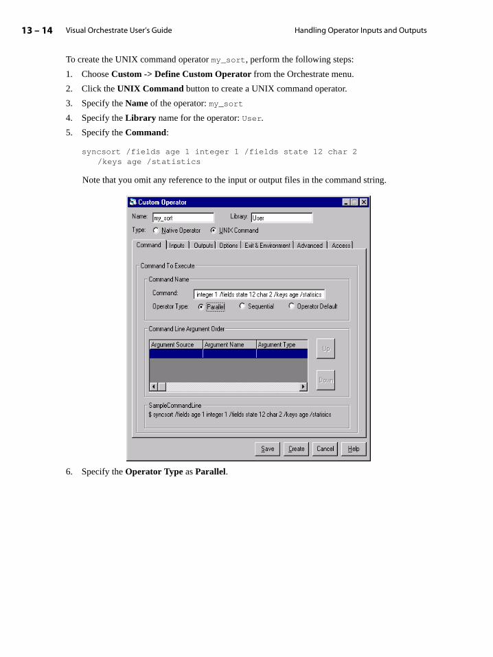
Visual Orchestrate User’s Guide13 – 14 Handling Operator Inputs and Outputs
To create the UNIX command operator my_sort, perform the following steps:
1. Choose Custom -> Define Custom Operator from the Orchestrate menu.
2. Click the UNIX Command button to create a UNIX command operator.
3. Specify the Name of the operator: my_sort
4. Specify the Library name for the operator: User.
5. Specify the Command:
syncsort /fields age 1 integer 1 /fields state 12 char 2 /keys age /statistics
Note that you omit any reference to the input or output files in the command string.
6. Specify the Operator Type as Parallel.
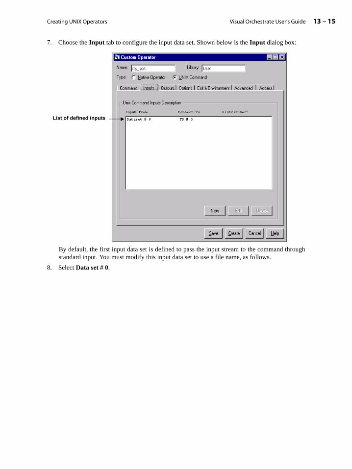
Creating UNIX Operators 13 – 15Visual Orchestrate User’s Guide
7. Choose the Input tab to configure the input data set. Shown below is the Input dialog box:
By default, the first input data set is defined to pass the input stream to the command throughstandard input. You must modify this input data set to use a file name, as follows.
8. Select Data set # 0.
List of defined inputs

Visual Orchestrate User’s Guide13 – 16 Handling Operator Inputs and Outputs
9. Press the Edit button to open the UNIX Command Input dialog box, shown below, to config-ure the input:
10. Specify the Orchestrate Input Link: 0
The first input data set is link 0, the second is link 1, and so forth.
11. Do not modify the Export Schema, as this example uses the default export schema.
12. Under Command Input, choose how the source data is delivered to the UNIX command. Thissetting defines how the data from the input data set is delivered to the UNIX command.
Click Program reads from a named file to indicate that the input data set is connected to thecommand using a file name.
13. Under Generated Filename Input select Pass filename on command line.
14. For Argument Name, specify /infile, the name of the SyncSort command-line argumentused to specify the input file.
15. Click OK to save the settings.
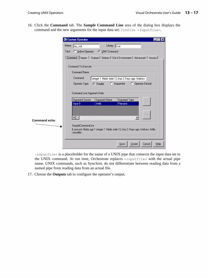
Creating UNIX Operators 13 – 17Visual Orchestrate User’s Guide
16. Click the Command tab. The Sample Command Line area of the dialog box displays thecommand and the new arguments for the input data set: /infile <inputfile>.
<inputfile> is a placeholder for the name of a UNIX pipe that connects the input data set tothe UNIX command. At run time, Orchestrate replaces <inputfile> with the actual pipename. UNIX commands, such as SyncSort, do not differentiate between reading data from anamed pipe from reading data from an actual file.
17. Choose the Outputs tab to configure the operator’s output.
Command echo
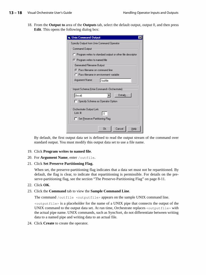
Visual Orchestrate User’s Guide13 – 18 Handling Operator Inputs and Outputs
f the
riting
18. From the Output to area of the Outputs tab, select the default output, output 0, and then pressEdit. This opens the following dialog box:
By default, the first output data set is defined to read the output stream of the command overstandard output. You must modify this output data set to use a file name.
19. Click Program writes to named file.
20. For Argument Name, enter /outfile.
21. Click Set Preserve Partitioning Flag.
When set, the preserve-partitioning flag indicates that a data set must not be repartitioned. Bydefault, the flag is clear, to indicate that repartitioning is permissible. For details on the pre-serve-partitioning flag, see the section “The Preserve-Partitioning Flag” on page 8-11.
22. Click OK.
23. Click the Command tab to view the Sample Command Line.
The command /outfile <outputfile> appears on the sample UNIX command line.
<outputfile> is a placeholder for the name of a UNIX pipe that connects the output oUNIX command to the output data set. At run time, Orchestrate replaces <outputfile> withthe actual pipe name. UNIX commands, such as SyncSort, do not differentiate between wdata to a named pipe and writing data to an actual file.
24. Click Create to create the operator.
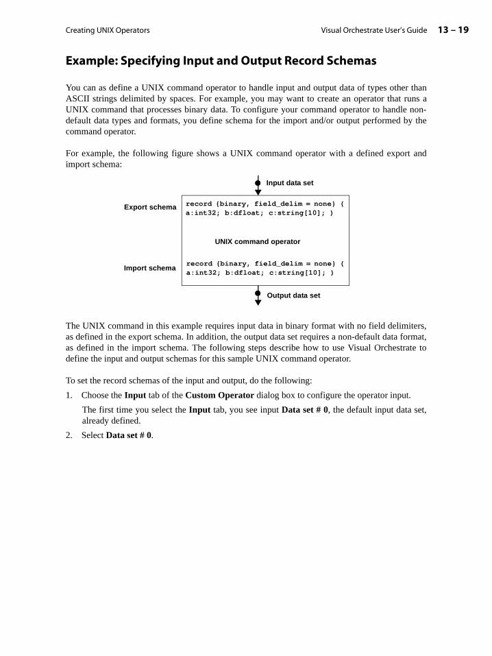
Creating UNIX Operators 13 – 19Visual Orchestrate User’s Guide
Example: Specifying Input and Output Record Schemas
You can as define a UNIX command operator to handle input and output data of types other thanASCII strings delimited by spaces. For example, you may want to create an operator that runs aUNIX command that processes binary data. To configure your command operator to handle non-default data types and formats, you define schema for the import and/or output performed by thecommand operator.
For example, the following figure shows a UNIX command operator with a defined export andimport schema:
The UNIX command in this example requires input data in binary format with no field delimiters,as defined in the export schema. In addition, the output data set requires a non-default data format,as defined in the import schema. The following steps describe how to use Visual Orchestrate todefine the input and output schemas for this sample UNIX command operator.
To set the record schemas of the input and output, do the following:
1. Choose the Input tab of the Custom Operator dialog box to configure the operator input.
The first time you select the Input tab, you see input Data set # 0, the default input data set,already defined.
2. Select Data set # 0.
UNIX command operator
record {binary, field_delim = none} (a:int32; b:dfloat; c:string[10]; )
record {binary, field_delim = none} (a:int32; b:dfloat; c:string[10]; )
Input data set
Output data set
Export schema
Import schema

Visual Orchestrate User’s Guide13 – 20 Handling Operator Inputs and Outputs
3. Press the Edit button to edit Data set # 0. This opens the UNIX Command Input dialog box,shown below:
4. Press the Details button to define the record schema for input data set 0. The Schema Editorwindow opens, as shown below:
Creating UNIX Operators 13 – 21Visual Orchestrate User’s Guide
e to
amed
imeeen
page
se one
you
5. Press New to define a new record schema.
6. Use the Schema Editor to define the input record schema shown in the figure above.
7. Press Save to save the record schema.
8. In the UNIX Command Input dialog box, choose how the records of the input data set aredelivered to the UNIX command. Choose either:
Program reads from standard input or other file descriptor
The UNIX command reads its input from standard input, or from a file descriptor that youspecify.
Program reads from named file
In this case, you have two options:
• Pass filename on command line
Specify the Argument Name. Orchestrate adds the argument name and a file namthe UNIX command in the form:
/arg_name <inputfile>
where arg_name is the value specified for Argument Name and <inputfile> is atemporary variable. At run time, Orchestrate replaces <inputfile> with a UNIXpipe name. UNIX commands do not differentiate between reading data over a npipe and reading data from an actual file.
• Pass filename in environment variable
Specify the Variable Name. Orchestrate creates the environment variable at run tand initializes it to a UNIX pipe name. UNIX commands do not differentiate betwreading data over a named pipe and reading data from an actual file.
See the section “Example: Passing File Names Using Environment Variables” on13-26 for an example using environment variables.
9. Click the Output tab to define the export schema of the output data set.
The first time you select the Output tab, you see input Data set # 0 already defined, as thedefault output data set.
10. Select Data set # 0.
11. Click the Edit button to edit Data set # 0.
12. Click the Details button to define the record schema. The Schema Editor window opens.
13. Use the Schema Editor to define the output record schema shown above.
14. Specify how the records of the input data set are delivered to the UNIX command. Chooof these two:
Program writes to standard output or other file descriptor
The UNIX command writes its output to standard output, or to a file descriptor thatspecify.
Program writes to named files
In this case, you have two options:
• Pass filename on command line
Visual Orchestrate User’s Guide13 – 22 Passing Arguments to and Configuring UNIX Commands
imeeen
sec-.
and to the com-e fol-
NIXrformts to the
he shellatory,
Specify the Argument Name. Orchestrate adds the argument name and a file name tothe UNIX command in the form:
/arg_name <outputfile>
where arg_name is the value specified for Argument Name and <outputfile> is atemporary variable. At run time, Orchestrate replaces <outputfile> with a UNIXpipe name. UNIX commands do not differentiate between writing data over a namedpipe and writing data to an actual file.
• Pass filename in environment variable
Specify the Variable Name. Orchestrate creates the environment variable at run tand initializes it to a UNIX pipe name. UNIX commands do not differentiate betwwriting data over a named pipe and writing data to an actual file.
For a description of passing environment variables to a UNIX command, see thetion “Example: Passing File Names Using Environment Variables” on page 13-26
Passing Arguments to and Configuring UNIX Commands
This section describes how to define your UNIX command operator to call the UNIX commwith a script for more flexibility in passing arguments, to define user-settable options to passUNIX command, to use environment variables to configure a UNIX command, and to handlemand input and output files with configuration and other information. This section covers thlowing topics:
• “Using a Shell Script to Call the UNIX Command” on page 13-22
• “Handling Message and Information Output Files” on page 13-24
• “Handling Configuration and Parameter Input Files” on page 13-25
• “Using Environment Variables to Configure UNIX Commands” on page 13-26
• “Example: Passing File Names Using Environment Variables” on page 13-26
• “Example: Defining User-Settable Options for a UNIX Command” on page 13-28
Using a Shell Script to Call the UNIX Command
You can define the operator so that it calls a UNIX shell script instead of directly calling the Ucommand or application. Using a script this way is useful when your operator must peprocessing on options passed to the operator, before it can pass those options as argumenUNIX command.
Orchestrate calls the shell script, passing it the dynamic options set by the operator user. Tscript parses the options and configures the UNIX command accordingly. While not mandusing a shell script is a convenient way to handle parameter parsing in Orchestrate.
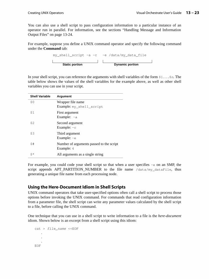
Creating UNIX Operators 13 – 23Visual Orchestrate User’s Guide
ation
mand
r shell
thoseationl script
You can also use a shell script to pass configuration information to a particular instance of anoperator run in parallel. For information, see the sections “Handling Message and InformOutput Files” on page 13-24.
For example, suppose you define a UNIX command operator and specify the following comunder the Command tab:
In your shell script, you can reference the arguments with shell variables of the form $1...$n. Thetable below shows the values of the shell variables for the example above, as well as othevariables you can use in your script.
For example, you could code your shell script so that when a user specifies -e on an SMP, thescript appends APT_PARTITION_NUMBER to the file name /data/my_dataFile, thusgenerating a unique file name from each processing node.
Using the Here-Document Idiom in Shell ScriptsUNIX command operators that take user-specified options often call a shell script to processoptions before invoking the UNIX command. For commands that read configuration informfrom a parameter file, the shell script can write any parameter values calculated by the shelto a file, before calling the UNIX command.
One technique that you can use in a shell script to write information to a file is the here-documentidiom. Shown below is an excerpt from a shell script using this idiom:
cat > file_name <<EOF...
EOF
Shell Variable Argument
$0 Wrapper file nameExample: my_shell_script
$1 First argumentExample: -a
$2 Second argumentExample: -c
$3 Third argumentExample: -e
$# Number of arguments passed to the scriptExample: 4
$* All arguments as a single string
my_shell_script -a -c -e /data/my_data_file
Static portion Dynamic portion

Visual Orchestrate User’s Guide13 – 24 Passing Arguments to and Configuring UNIX Commands
In this example, cat writes everything after <<EOF to the file named file_name, until itencounters an EOF on a line by itself. This procedure lets you calculate values from user-suppliedoptions in the shell script and write those values to the parameter file.
Handling Message and Information Output Files
UNIX commands can create output files containing messages (information and error log files) oroutput summaries. For operator outputs that do not contain data, the command can write directly tothe files without using an Orchestrate data set. Suppose, for example, that you want to run a UNIXcommand with the form:
unix_command options -e error_file
This command creates a file containing any error messages that the command generates.
When executing this command in parallel with a UNIX command operator, you can let thecommand generate a file on each processing node, as shown in the following figure:
On an MPP, each processing node has its own disk storage. The UNIX command writes its outputfiles to the local disk storage on the processing node. Upon completion of the Orchestrateapplication, you can examine the output files.
On an SMP, all processing nodes frequently share disk drives. You must assign unique names tothe output files, so that a file generated by one processing node does not overwrite a file generatedby another processing node.
You can define the UNIX operator to call a shell script to execute the UNIX command. You codethe shell script to create a unique file name for each error file. For example, the following shellscript executes unix_command on an SMP:
#!/bin/kshmy_command options -e error_file.$APT_PARTITION_NUMBER
APT_PARTITION_NUMBER is an environment variable, set by Orchestrate, that contains thepartition number of the operator on each processing node. If an operator has three partitions (runson three processing nodes), Orchestrate sets APT_PARTITION_NUMBER to 0 on the firstprocessing node, 1 on the second, and 2 on the third processing node. Therefore, this shell scriptwould create three output files: error_file.0, error_file.1, and error_file.2.
UNIX operator Processing nodes ...
Output files
Creating UNIX Operators 13 – 25Visual Orchestrate User’s Guide
more
eterator’s your
.
ith its same
e diskaccess
pagessing
By using APT_PARTITION_NUMBER, you guarantee that each instance of the UNIX commandoperator on an SMP creates an error file with a unique name. When the operator runs again, it willoverwrite all the error files.
Note that you must create a shell script to run the command shown above. You cannot use theCommand tab in the Custom Operator dialog box to enter and run the command, becauseOrchestrate evaluates the command in the Command tab at the time you invoke your application.At invocation time, APT_PARTITION_NUMBER evaluates to the number of the processing nodethat invokes the application; therefore, each processing node executing the command would use thesame value for APT_PARTITION_NUMBER.
A shell script, by contrast, is executed only when the operator runs on each processing node, so thatAPT_PARTITION_NUMBER evaluates to the number of the processing node executing the shellscript.
See the section “Using a Shell Script to Call the UNIX Command” on page 13-22 for information.
Handling Configuration and Parameter Input Files
Many UNIX commands and applications take input files that contain configuration or paraminformation. You then modify the input file instead of editing the operator to change the operaction. This section describes how to use files as input to the UNIX command called byoperator.
For example, the following command line, specified in the Command tab of the Custom Opera-tor dialog box, uses a parameter file:
unix_command options -p p_file
In this example, the command reads the parameter file p_file to determine the command’s action
On an MPP, each instance of a parallel operator executes on a different processing node, wown disk storage. You must make sure that there is a copy of the parameter file in thedirectory on each processing node executing the operator.
On an SMP, all processing nodes, corresponding to the CPUs in the system, frequently sharstorage. You need only one copy of the file, as all instances of the operator on the SMP will the same file.
You can also use the environment variable APT_PARTITION_NUMBER and a shell script to exe-cute the UNIX command, as described in the section “Handling Command Exit Codes” on13-35. Using a shell script enables you create a different configuration file for each procenode. For example, you could invoke the command in the following shell script:
#!/bin/kshunix_command options -p p_file.$APT_PARTITION_NUMBER

Visual Orchestrate User’s Guide13 – 26 Passing Arguments to and Configuring UNIX Commands
that
et con-g envi-
way,
name.rator,
oper-
ains the of an
name.g data
This shell script causes the command to look for a parameter file named p_file.0 on the firstprocessing node, p_file.1 on the second processing node, and so forth.
Using Environment Variables to Configure UNIX Commands
One common way to configure a UNIX command is to use environment variables. Environmentvariables can define the location of system resources or hold configuration options for a command.For a UNIX command to access an environment variable, the variable must be set in the UNIXshell that invokes the command.
To run a command from a UNIX command operator, Orchestrate first creates a UNIX shell usingthe login name of the user invoking the application. The shell contains environment variablesdefined by the user’s execution environment.
In addition, in defining your UNIX command operator, you can create environment variableshold the following:
• File names used as inputs to or outputs from a command.
You create these environment variables when you configure the input and output data snections used by the operator. The example below describes how to pass file names usinronment variables.
• Configuration settings for the command.
The Exit & Environment tab area of the Custom Operator dialog box lets you define envi-ronment variables that Orchestrate will set before it invokes your UNIX command. In thisyou can pass information to the command.
Example: Passing File Names Using Environment Variables
Many UNIX commands access an environment variables to determine an input or output file In addition to letting you handle command-line arguments to a UNIX command in your opeOrchestrate lets you define your UNIX command operator to handle environment variables.
Suppose, for example, that you want to run the following command using a UNIX commandator:
filter args
This command filters its input based on the arguments passed to it. The command also obtname of an input file by the value of the environment variable FILTER_INPUT, and the nameoutput file from the environment variable FILTER_OUTPUT.
Orchestrate creates the environment variable at run time and initializes it to a UNIX pipe UNIX commands do not differentiate between reading data from a named pipe and readinfrom an actual file.
Creating UNIX Operators 13 – 27Visual Orchestrate User’s Guide
To define the environment variables for this example, do the following:
1. Choose the Input tab of the Custom Operator dialog box to configure the operator input.
2. Select Data set # 0.
3. Press the Edit button to edit Data set # 0. This opens the UNIX Command Input dialog box.
4. In the UNIX Command Input dialog box, choose how the records of the input data set aredelivered to the UNIX command. Select the following:
Program reads from named file
5. Choose how the file name is passed to the UNIX command. For this example, select the fol-lowing:
Pass filename in environment variable
6. Specify the Variable Name: FILTER_INPUT.
Orchestrate creates the environment variable at run time and initializes it to a UNIX pipename.
7. Click the Output tab to define the export schema of the output data set.
8. Select Data set # 0.
9. Click the Edit button to edit Data set # 0.
10. Choose how the record of the input data set are delivered to the UNIX command. Choose:
Program writes to named files
11. Specify how the file name is passed to the UNIX command. For this example, select the fol-lowing:
Pass filename in environment variable
12. Specify the Variable Name: FILTER_OUTPUT.
Orchestrate creates the environment variable at run time and initializes it to a UNIX pipename.
Example: Defining an Environment Variable for a UNIX Command
In this example, a UNIX operator executes a UNIX command that uses the environment variableMY_ENV_VAR to determine the location of its parameter file. To configure the UNIX commandoperator to set that environment variable, perform the following steps:
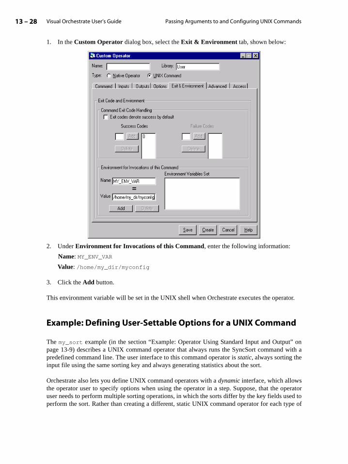
Visual Orchestrate User’s Guide13 – 28 Passing Arguments to and Configuring UNIX Commands
t” on with a
peratorsed toype of
1. In the Custom Operator dialog box, select the Exit & Environment tab, shown below:
2. Under Environment for Invocations of this Command, enter the following information:
Name: MY_ENV_VAR
Value: /home/my_dir/myconfig
3. Click the Add button.
This environment variable will be set in the UNIX shell when Orchestrate executes the operator.
Example: Defining User-Settable Options for a UNIX Command
The my_sort example (in the section “Example: Operator Using Standard Input and Outpupage 13-9) describes a UNIX command operator that always runs the SyncSort commandpredefined command line. The user interface to this command operator is static, always sorting theinput file using the same sorting key and always generating statistics about the sort.
Orchestrate also lets you define UNIX command operators with a dynamic interface, which allowsthe operator user to specify options when using the operator in a step. Suppose, that the ouser needs to perform multiple sorting operations, in which the sorts differ by the key fields uperform the sort. Rather than creating a different, static UNIX command operator for each t

Creating UNIX Operators 13 – 29Visual Orchestrate User’s Guide
forerator
sort operation, you can create a single, dynamic sort operator that allows the user to passconfiguration options to the operator.
To create a dynamic command operator, you define at least part of the UNIX command as dynamic.For example, in the Command tab you could specify the following as the static portion of thesample UNIX command above:
syncsort /fields age 1 integer 1 /fields state 12 char 2
The static portion of this command defines the data format of the sorted data, but does not specifythe sorting keys or statistics option. The dynamic portion of the command lets the user optionallyspecify the /key and /statistics options. The operator user can specify one, both, or neitheroption to the operator each time the operator is invoked in a step.
This example describes how to create a command operator that lets the operator user set twooptions. It also describes how the operator user sets the options, and the results of setting theoptions.
Adding Options to an OperatorTo create a sort operator that takes user-settable options, perform the following steps:
1. Create the my_sort operator as described in the section “Example: Operator Using FilesInput and Output” on page 13-13. However, instead of the command line used in that opdefinition, enter the following command line in the Command tab:
syncsort /fields age 1 integer 1 /fields state 12 char 2
Note that this command line contains no specification for /keys or /statistics.
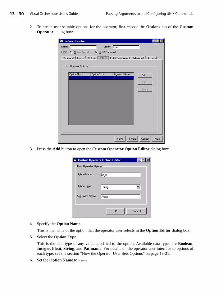
Visual Orchestrate User’s Guide13 – 30 Passing Arguments to and Configuring UNIX Commands
2. To create user-settable options for the operator, first choose the Options tab of the CustomOperator dialog box:
3. Press the Add button to open the Custom Operator Option Editor dialog box:
4. Specify the Option Name.
This is the name of the option that the operator user selects in the Option Editor dialog box.
5. Select the Option Type.
This is the data type of any value specified to the option. Available data types are Boolean,Integer, Float, String, and Pathname. For details on the operator user interface to options ofeach type, see the section “How the Operator User Sets Options” on page 13-31.
6. Set the Option Name to keys.
Creating UNIX Operators 13 – 31Visual Orchestrate User’s Guide
ecifies
, as
serts then the
ptions.
Note that Orchestrate sets the default Argument Name to -keys.
7. Set the Option Type to String.
You let the user specify a string as the option’s value, because the /keys argument takes astring specifying one or more sorting keys, separated by commas.
8. Set the Argument Name to /keys.
9. Click OK to close the Custom Operator Option Editor.
10. Click Add to add the stats option.
11. Set the Option Name to stats.
12. Set the Option Type to Boolean.
A flag argument means that the option takes no additional value from the user.
13. Set the Argument Name to /statistics.
14. Click OK.
15. Click the Command tab to view the command. Note that the Sample Command Line showsboth arguments. These arguments will be included in the command only if the user spthem when using the operator in a step.
Also note that the options appear in the Command Line Argument Order list. You can usethe Up and Down buttons to change the order of the arguments to the UNIX commandreflected in the Sample Command Line area.
16. Press Create to create the operator.
An operator user inserting this operator into a step can now specify the key option to set the sortingkeys and the stats option to enable statistic generation.
How the Operator User Sets OptionsTo access the user-settable options on this sample command operator, the operator user inoperator into the application. Then, the operator user double clicks the operator to opeOperator Properties dialog box. The user presses the Add button to open the Option Editordialog box. From the list in that dialog box, the user selects and sets one or more operator o

Visual Orchestrate User’s Guide13 – 32 Passing Arguments to and Configuring UNIX Commands
Shown below are the Operator Properties dialog box, and the Option Editor dialog box aftereach option (keys and stats) has been selected:
For the key option in this example, the operator can specify one or more sorting keys, separated bycommas. For the stats option, simply specifying stats enables the option.
Below are detailed descriptions of the operator user interface for options of each supported type.
Setting Boolean OptionsOptions with the type Boolean do not take a value. Specifying the option name is all that isrequired. For example, the SyncSort /statistics option does not require a value; simply speci-fying the option enables the generation of sorting statistics.
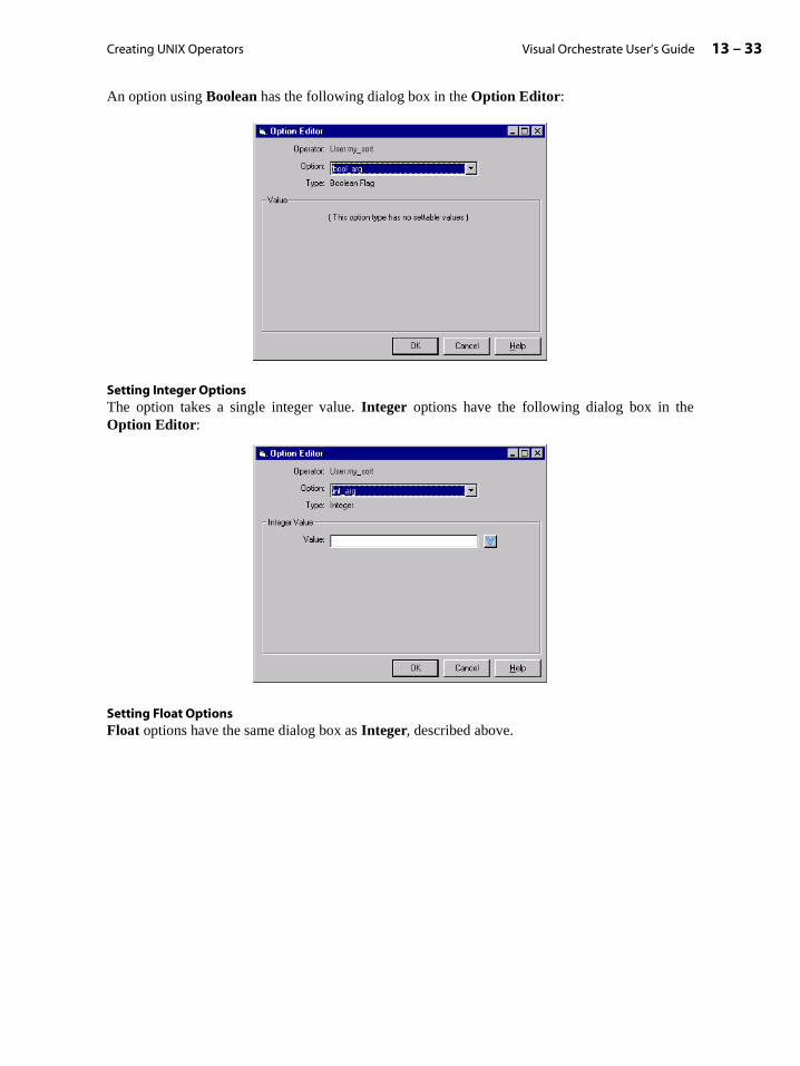
Creating UNIX Operators 13 – 33Visual Orchestrate User’s Guide
An option using Boolean has the following dialog box in the Option Editor:
Setting Integer OptionsThe option takes a single integer value. Integer options have the following dialog box in theOption Editor:
Setting Float OptionsFloat options have the same dialog box as Integer, described above.
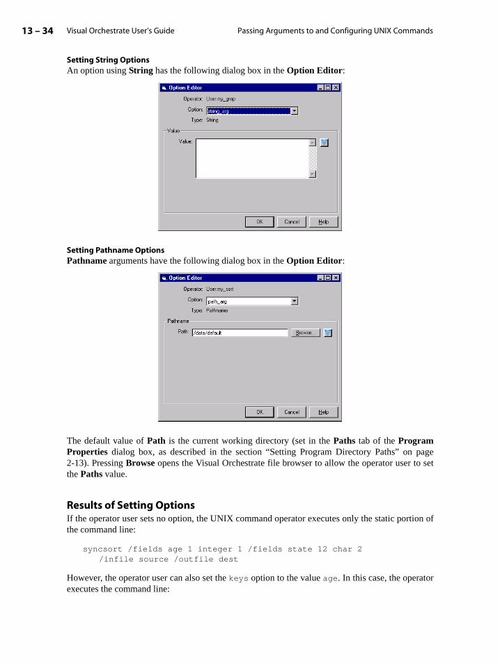
Visual Orchestrate User’s Guide13 – 34 Passing Arguments to and Configuring UNIX Commands
pageo set
tion of
r
Setting String OptionsAn option using String has the following dialog box in the Option Editor:
Setting Pathname OptionsPathname arguments have the following dialog box in the Option Editor:
The default value of Path is the current working directory (set in the Paths tab of the ProgramProperties dialog box, as described in the section “Setting Program Directory Paths” on 2-13). Pressing Browse opens the Visual Orchestrate file browser to allow the operator user tthe Paths value.
Results of Setting OptionsIf the operator user sets no option, the UNIX command operator executes only the static porthe command line:
syncsort /fields age 1 integer 1 /fields state 12 char 2 /infile source /outfile dest
However, the operator user can also set the keys option to the value age. In this case, the operatoexecutes the command line:

Creating UNIX Operators 13 – 35Visual Orchestrate User’s Guide
syncsort /fields age 1 integer 1 /fields state 12 char 2 /keys age /infile source /outfile dest
A user specifying the stats option and the key option with a value of age would invoke the com-mand line:
syncsort /fields age 1 integer 1 /fields state 12 char 2 /keys age /statistics /infile source /outfile dest
Handling Command Exit Codes
All UNIX commands return an exit code indicating the success, failure, or other result of the com-mand. Orchestrate interprets the exit code when it executes a UNIX command operator, to deter-mine whether the command has executed successfully. You can control how Orchestrate interpretsexit codes.
Note: If, for any reason, the UNIX command returns an exit code that Orchestrate interprets as afailure, the operator fails. When any operator in a step fails, Orchestrate terminates the entire step.
When you create a UNIX command operator, you use the Exit & Environment tab in the CustomOperator dialog box to define how Orchestrate interprets exit codes. This tab is shown below:

Visual Orchestrate User’s Guide13 – 36 How Orchestrate Optimizes Command Operators
odes
odes to
ault aowing
mand,le, on a
ator.
By default, Orchestrate interprets an exit code of 0 as a success and all other exit codes as a failure.
In the Command Exit Code Handling area you can set the following options:
• Exit codes default successful: Causes all exit codes to be treated as success, except cexplicitly designated as errors using Failure Codes. Ignores any settings defined by SuccessCodes.
• Success Codes: Specifies exit codes defining successful execution of the command; all cthat you have not specified as Success Codes are considered errors. Configures Orchestrateignore any settings defined by Failure Codes.
You can specify either Success Codes or Exit codes default successful, but not both. Some com-mon specifications are:
• Success Codes = 0 and 1: Exit codes 0 and 1 indicate success; all others are errors.
• Exit codes default successful selected: All exit codes indicate success.
• Exit codes default successful selected and Failure Codes = 1: All exit codes other than 1indicate success; exit code 1 indicates an error.
How Orchestrate Optimizes Command Operators
As described in the section “Execution of a UNIX Command Operator” on page 13-5, by defUNIX command operator consists of the three parts shown on the right-hand side of the follfigure:
When executing the operator, Orchestrate creates one UNIX process each for the export, comand import parts of the operator on each processing node executing the operator. For exampfour node system, Orchestrate creates 12 UNIX processes for the four instances of the oper
UNIX operator
export
import
UNIX command

Creating UNIX Operators 13 – 37Visual Orchestrate User’s Guide
mand
on theree of
same
hema,t of theple, ifexport import
This section describes how Orchestrate can optimize your UNIX command operator. In many ofthese optimizations, Orchestrate skips either the export or the import process.
This section covers the following topics:
• “Cascading UNIX Command Operators” on page 13-37
• “Using Files as Inputs to UNIX Command Operators” on page 13-38
• “Using FileSets as Command Operator Inputs and Outputs” on page 13-39
• “Using Partial Record Schemas” on page 13-39
Cascading UNIX Command Operators
In creating an Orchestrate step, you can cascade (connect in succession) UNIX comoperators, as shown below:
By default, Orchestrate performs an import on the output of the first operator and an export input of the second. However, Orchestrate eliminates both the import and the export, if all ththe following conditions are met:
• Both operators have the same execution mode (parallel or sequential).
• Both operators have the same constraints.
• The output port of the first operator and the input port of the second operator use therecord schema.
The last condition is the most important. If the two ports do not have the same record scOrchestrate must perform the export and the import operations in order to convert the outpufirst operator to the record format required by the UNIX command of the second. For examthe first operator specifies an ASCII text mode representation of the imported data, but the of the second operator specifies a binary representation, Orchestrate must perform both theand the export.
UNIX operator
UNIX operator
May be bypassed
import
export
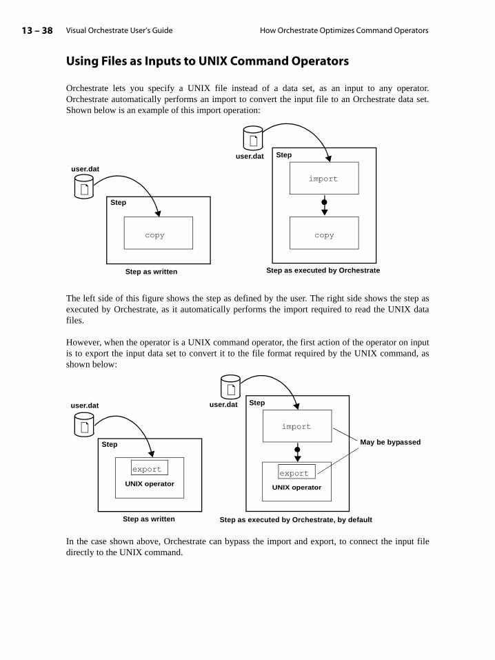
Visual Orchestrate User’s Guide13 – 38 How Orchestrate Optimizes Command Operators
Using Files as Inputs to UNIX Command Operators
Orchestrate lets you specify a UNIX file instead of a data set, as an input to any operator.Orchestrate automatically performs an import to convert the input file to an Orchestrate data set.Shown below is an example of this import operation:
The left side of this figure shows the step as defined by the user. The right side shows the step asexecuted by Orchestrate, as it automatically performs the import required to read the UNIX datafiles.
However, when the operator is a UNIX command operator, the first action of the operator on inputis to export the input data set to convert it to the file format required by the UNIX command, asshown below:
In the case shown above, Orchestrate can bypass the import and export, to connect the input filedirectly to the UNIX command.
copy
Step
user.dat
copy
Step
import
Step as written Step as executed by Orchestrate
user.dat
UNIX operator
Step
user.dat Step
import
Step as executed by Orchestrate, by defaultStep as written
export
UNIX operator
export
May be bypassed
user.dat

Creating UNIX Operators 13 – 39Visual Orchestrate User’s Guide
t, or, notntain a fileset
the
dreds.sortingxportyour
If an input file has the same record schema as the operator input interface, then the UNIX commandoperator directly reads the file. If the operator executes in parallel on an SMP, each instance of theoperator directly reads the file, in parallel.
Using FileSets as Command Operator Inputs and Outputs
The previous section described how Orchestrate optimizes a UNIX command operator when youspecify a file as the operator’s input or output. You can also specify a fileset as an operator’s inputor output. A fileset is an ASCII text file that contains either a list of UNIX source files for inpua list of destination files for output. The files referenced by a fileset are UNIX data filesOrchestrate data sets. The fileset must contain one file name per line and can optionally corecord schema defining the layout of the data in the data files. All data files referenced by themust have the same layout.
You can use the Orchestrate operator export to create a fileset, as described in the chapter onexport operator in the Orchestrate User’s Guide: Operators. Or if you wish, you can create afileset using a text editor outside the Orchestrate environment.
Orchestrate optimizes the data access of filesets by parallel UNIX command operators in much thesame way that it optimizes for individual files. If, on input, the fileset has the same record schemaas the input port of the operator, Orchestrate bypasses the export operation and connects the filesetdirectly to the UNIX command. If, on output, the fileset has the same record schema as defined forthe output port of the operator, Orchestrate bypasses the import and writes the data directly to thefileset.
Using Partial Record Schemas
When importing data using an Orchestrate partial record schema, you define only the fields ofinterest in your data. Your records may contain many individual fields — perhaps even hunHowever, to process the records, your application may access only a few fields to use as keys, partitioning keys, or input fields to Orchestrate operators. You can simplify the import/eprocedure by providing only enough schema information to identify the fields required by application. See the chapters on the import and export operators in the Orchestrate User’sGuide: Operators for a complete description of partial record schemas.
Shown below is a sample record schema with field information for only two fields:
The following record schema defines the two fields of this record:
record { intact=rName, record_length=82, record_delim_string=’\r\n’ }( name: string[20] { position=12, delim=none };
Record after import, as stored in a data set
name:string[20] income:dfloat
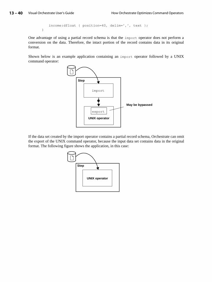
Visual Orchestrate User’s Guide13 – 40 How Orchestrate Optimizes Command Operators
income:dfloat { position=40, delim=’,’, text };)
One advantage of using a partial record schema is that the import operator does not perform aconversion on the data. Therefore, the intact portion of the record contains data in its originalformat.
Shown below is an example application containing an import operator followed by a UNIXcommand operator:
If the data set created by the import operator contains a partial record schema, Orchestrate can omitthe export of the UNIX command operator, because the input data set contains data in the originalformat. The following figure shows the application, in this case:
Step
import
UNIX operator
export
May be bypassed
UNIX operator
Step
I – 1Visual Orchestrate User’s Guide
Index
Aaccessors 4-17aggregate data types
subrecord 3-6tagged 3-6
aggregate fieldsin input data sets 5-7
applicationscomponents of 1-4creating 2-1deploying 2-2, 2-6display-intensive 6-8multiple-step 6-4performance
effect of output display 6-8running 2-7single-step 6-3steps in 6-4validating 2-6
APT_Collector class 9-3APT_CONFIG_FILE 1-14APT_Date class 12-21APT_Decimal class 12-23APT_ERROR_CONFIGURATION 11-4APT_Partitioner class 8-4APT_RawField class 12-25APT_StringField class 12-24APT_Time class 12-21APT_TimeStamp class 12-21APT_WRITE_DS_VERSION 4-33arcs
performance monitor display of 7-4
Bbranching
in steps 6-3
Ccluster/MPP systems
See MPP systems
collecting 9-1defined 9-2method 9-1
any 9-3ordered 9-3other 9-3round robin 9-3sorted merge 9-3
operators and 9-2preserve-partitioning flag and 9-2
collection method 9-1any 9-3
example of use 9-5ordered 9-3other 9-3round robin 9-3sorted merge 9-3
example of use 9-6collectors
defined 9-1See also collecting
components of Orchestrate application 1-4configuration file
disk pools and 10-4node allocation and 1-3, 10-2node definitions and 10-5node pools and 10-2
Constraint Editor dialog box 10-6, 10-8constraints
applying 1-10, 10-1combining node and resource 10-8data sets and 10-9logical nodes and 10-2, 10-4, 10-5MPP systems 10-2node definitions and 10-5node maps and 10-1node pools and 10-1operators and 10-1Orchestrate configuration file and 10-5resource pools and 10-1
Visual Orchestrate User’s GuideI – 2
Index
SMP systems 10-4creating operators 12-1Custom Operator dialog box 12-5, 13-10custom operators
action of 12-3arguments to 12-2C++ compiler for 12-4characteristics 12-2coding
data types and 12-20examples 12-32, 12-34for multiple inputs 12-32
creating 12-7date fields and 12-21decimal fields and
example 12-23defined 12-1example 12-15, 12-16, 12-17, 12-21execution mode 12-2execution of 12-8, 12-31flow-control macros 12-27functions
[index] 12-26_clearnull() 12-26_null() 12-26_setnull() 12-26fieldname_clearnull() 12-26fieldname_null() 12-26fieldname_setnull() 12-26setVectorLength() 12-26vectorLength() 12-26
I/O macros 12-28examples 12-28
included header files 12-4informational macros 12-27input and output interfaces
defining 12-9input data sets and 12-4input interface 12-6input interface schema 12-8input ports
indexing 12-9naming 12-9
inputsauto read 12-9, 12-32, 12-34noauto read 12-34
interface schema and 12-10, 12-13input 12-10, 12-13
nullable fields 12-25output 12-10, 12-13vector fields 12-26
interface schemasnull fields in 12-25
introduction to 1-10macros 12-27
discardRecord() 12-28discardTransfer() 12-28doTransfer() 12-29doTransfersFrom() 12-29doTransfersTo() 12-29endLoop() 12-27failStep() 12-27holdRecord() 12-28inputDone() 12-28inputs() 12-27nextLoop() 12-27outputs() 12-27readRecord() 12-28transferAndWriteRecord() 12-29transfers() 12-27writeRecord() 12-28
nullable fields and 12-25numeric fields and 12-21option definition 12-7options for 12-17
data types of 12-19defining 12-20
Orchestrate server administrator and 12-4output data sets and 12-4output interface 12-6output interface schema 12-8output ports
indexing 12-9naming 12-9
outputsauto write 12-9
partitioning method 12-2Per-record code 12-6Post-loop code 12-7Pre-loop code 12-7processing loop 12-3raw fields and
example 12-25reject output
example 12-30saving 12-7

IndexI – 3
Visual Orchestrate User’s Guide
See also native operatorsstring fields and
example 12-24time fields and 12-21timestamp fields and 12-21transfer macros 12-29
examples 12-30transfers and 12-2, 12-16user options for
data types of 12-19user-settable options for 12-18using 12-1vector fields and 12-26
Ddata flow 1-5
See data-flow modelsdata flows
performance monitor display of 7-4Data Set Properties dialog box 4-8Data Set Viewer 4-14
data sets and 4-14using 4-14
data setsas input to operators 5-10as output from operators 5-10configuring 4-8constraints and 10-9
syntax 10-9using 10-9
creatingorchadmin and 4-35
Data Set Properties dialog box 4-8Data Set Viewer and 4-14dialog box 4-8disk pools and 10-9export and 4-7file naming 4-37flat files 1-8import and 4-7introduction to 1-5Link Properties dialog box and 4-11multiple inputs and 4-4multiple outputs and 4-4operators and 4-3
data type compatibility 3-8, 5-17Orchestrate version and 4-33output
record schema 5-8parallel representation 4-32
data files 4-32descriptor file 4-32segments 4-32
partitioning 1-2, 1-9, 4-7disk pools and 10-10
performance monitor and 7-4persistent
examples 4-6record count 4-16viewing 4-14
record fieldsdefault value 4-27
record schema 1-6representation of 4-32segments and 4-32storage format 4-33structure of 4-1, 4-32viewing 4-14virtual
examples 4-5data type conversions
data set fields and 3-8, 5-17default 3-9
examples 3-10modify and 3-9
examples 3-10operators and 3-8, 5-17record schemas and 3-8
data typescompatibility 5-17conversion
errors 5-17string and decimal fields 5-20warnings 5-17
conversions 5-17date 3-2decimal 3-4floating-point 3-5integer 3-6introduction to 3-1nulls 3-2raw 3-6string 3-6subrecord 3-6tagged 3-6time 3-6
Visual Orchestrate User’s GuideI – 4
Index
timestamp 3-7data-flow diagrams
See data-flow modelsdata-flow models
and steps 6-2definition of 1-5directed acyclic graph 6-2partitioning and 8-5UNIX command operators and 13-7
date 3-2range 3-2
date data typeSee data types
datedate fields 4-20
data type 4-20schema definition of 4-20
DB2DB2 partitioner 8-4partitioning and 8-4
decimal 3-4assignment to
strings and 3-5precision
range 3-4range 3-5representation size 3-4scale
range 3-4sign nibble 3-4
values 3-4strings and 3-5valid representation 3-4zero representation 3-4
decimal data typeSee data types
decimaldecimal fields 4-21
data type 4-21precision limit 4-21range limit 4-21schema definition of 4-21
default valuerecord fields 4-27
development environment 2-1dialog box
Constraint Editor 10-6, 10-8Custom Operator 12-5
UNIX Command 13-10Data Set Properties 4-8Data Set Viewer 4-14Input Interface Editor 12-9Link Properties 4-11, 8-14Operator Properties 5-4, 6-14, 10-6Option Editor 5-5Output Interface Editor 12-9Program Editor 10-6Program Properties 2-4Step Properties 6-6
directed acyclic graphdefined 6-2
disk pools 10-1, 10-4assigning data sets to 10-9constraining operators to 10-10data set partitions and 10-10data sets and 10-4
disksallocating 10-5constraints and 10-5node definitions and 10-5
Eenumerated fields 5-13environment variables
APT_CONFIG_FILE 1-14APT_PARTITION_NUMBER 13-24APT_WRITE_DS_VERSION 4-33setting 6-10
error handling 5-18error log 11-1error messages
default components 11-4display control
APT_ERROR_CONFIGURATION and 11-4
default display 11-4keywords 11-4
example 11-4keywords
errorIndex 11-2ipaddr 11-3jobid 11-2lengthprefix 11-3message 11-3moduleId 11-2nodename 11-3

IndexI – 5
Visual Orchestrate User’s Guide
nodeplayer 11-3opid 11-3severity 11-2timestamp 11-2vseverity 11-2
subprocesses anddefault display 11-3
errorserror log 11-1reporting 11-1
Excelperformance monitor spreadsheet and 7-8
execution modeSee operators
execution modeExecution Window
message headers and 2-10text wrap and 2-10
export 4-7
Ffield accessors 4-17field adapters
schema variables and 5-13fields
and schema variables 5-13enumerated 5-13fixed-length 4-1See record fieldsvariable-length 4-1
fixed-length field 4-1fixed-length records 4-1flat files 1-8floating-point data type
See data typesfloating-point
floating-point fieldsschema definition 4-21
Gget_orchserver_variable 6-13grids
performance monitor display 7-7group operator
and partitioning 8-7
Hhash partitioner
characteristics 8-9key field distribution 8-10using 8-9
hash partitioning 8-9header files
for custom operators 12-4here-document idiom
UNIX command operators and 13-23
Iimport 4-7import/export utility 4-7Input Interface Editor dialog box 12-9integer data type
See data typesinteger
integer fieldsrecord schema 4-21
Jjob-manager 2-7
examples 2-7, 2-8syntax 2-7
abandon 2-8errors 2-9kill 2-8, 2-9run 2-8
Llink numbers
enabling 2-9Link Properties
Adapters tab 4-10Advanced tab 4-10dialog box 4-10Schema tab 4-10
Link Properties dialog box 4-11, 8-14links 4-10
configuring 4-10persistent data sets and 4-10
Lock Manager 2-15locking objects 2-15locks
clearing 2-15in Visual Orchestrate 2-15
logical nodes 10-2, 10-4configuring 10-5
Visual Orchestrate User’s GuideI – 6
Index
Mmassively parallel processing 1-3memory
setting in Visual Orchestrate 6-9messages
error 11-1error log 11-1Orchestrate format 11-2warning 5-18, 11-1
modify operatorconversions with 5-18data type conversions and 3-10preventing errors with 5-18suppressing warning messages with 5-18
movie filesperformance monitor and 7-10
MPP systemsconstraints and 10-2performance and 1-3UNIX command operators and 13-24
Nnaming
fields 4-19native operators
defined 12-1See also custom operators
node definitions 10-5node maps 10-1, 10-8
constraining operators to 10-8default 10-8example 10-8operators and 10-1using 10-8
node names 10-5node pool constraints 10-6
data sets and 10-6operators and 10-6syntax 10-6using 10-6
node pools 10-1, 10-2, 10-5default operator usage 10-1
normalized tabledata sets and 4-2
nullability 4-3introduction to 3-2See nullsVectors and 4-24
nullable fieldsintroduction to 3-2
nulls 3-2, 4-3data types and 3-2default value of 4-27defined 4-19handling 4-19representation of 4-19vectors and 4-19
Ooperator interface schema 5-6
data set compatibility 3-8, 5-7, 5-17aggregate fields 5-21date fields 5-20decimal fields 5-19nulls and 5-21string and numeric fields 5-18time fields 5-20timestamp fields 5-20vector fields 5-21
data type conversion 3-8matching to input data sets 3-8, 5-17output data sets and 5-8schema variables 5-11
Operator Properties dialog box 6-14, 10-6operators
and output data sets 5-8collecting and 9-1configuring 5-3
Operator Properties dialog box and 5-4Option Editor 5-5
constraining 10-1constraints
node maps and 10-8node pools and 10-6
creating 13-1custom operators and 12-1See custom operators
creating steps from 6-2data sets with 4-3, 5-2data type conversions 3-8disk pools
constraining to 4-36, 10-6, 10-7dynamic interface schema
example 5-15input schema 5-15output schema 5-15

IndexI – 7
Visual Orchestrate User’s Guide
setting interface schema 5-15using 5-15
errors and 11-1execution mode 1-10
controlling 5-2parallel 5-2sequential 5-2
input data sets with 5-7inputs 5-1interface schema 5-6
defined 5-6introduction to 1-10multiple inputs and outputs 5-1node maps 10-1
constraining to 10-8node pools 10-1
constraining to 4-36, 10-6default usage of 10-1
nulls fields and 5-21Operator Properties dialog box 5-4Option Editor 5-5output data sets and 5-8outputs 5-1parallel execution of 1-9partitioning
preserve-partitioning flag and 8-11partitioning and 8-1performance monitor and 1-13prebuilt 1-10preserve-partitioning flag and 8-11resource pools
constraining to 4-36, 10-6, 10-7resources
constraining to 4-36, 10-6, 10-7schema variables and 5-11UNIX command operators 13-1
creating 13-1vector fields and 5-21
Option Editor 5-5Orchestrate
configuration filedefault 2-12validating 2-14
data types 3-1date 3-2decimal 3-4floating-point 3-5integer 3-6
raw 3-6string 3-6subrecord 3-6tagged 3-6time 3-6timestamp 3-7
development environment 2-1disk pools and 10-4
Orchestrate Analytics Library (optional)and partitioning 8-8
Orchestrate application developmentparallel execution mode 1-14sequential execution mode 1-14
Orchestrate applicationscreating 2-1See also applications
Orchestrate classesAPT_Collector 9-3APT_Date 12-21APT_Decimal 12-23APT_Partitioner 8-4APT_RawField 12-25APT_StringField 12-24APT_Time 12-21APT_TimeStamp 12-21
Orchestrate Installation and Administration Manual 1-14
Orchestrate server administrator 2-2orchview
invoking 7-4See also performance monitor
oshconstraints and
combined node and resource 10-8Visual Orchestrate and 2-15
Output Interface Editor dialog box 12-9
Pparallelism
partition 1-2pipeline 1-2
partial record schema 4-18partial record schemas
UNIX command operators and 13-39partial schema definition 4-18partition parallelism 1-2partitioners
See partitioning
Visual Orchestrate User’s GuideI – 8
Index
partitioningdata sets 1-2, 1-9, 4-7fan-in 8-6fan-out 8-6method 8-1
DB2 8-4entire 8-4, 8-5examples 8-5hash 8-4modulus 8-4other 8-4random 8-4, 8-8range 8-4round robin 8-4, 8-7same 8-4, 8-5selecting 8-8
operatorskeyed 8-9keyless 8-9selecting 8-8
operators and 8-1parallel operators and 8-6preserve-partitioning flag and 8-11sequential operators and 8-6
partitioning method 8-1, 8-3any 8-4DB2 8-4default 8-4entire 8-4, 8-5hash 8-4modulus 8-4other 8-4random 8-4, 8-8range 8-4round robin 8-4same 8-4, 8-5
partitioning operatorsSee partitioning
partitionsnumber of 8-8See also partitioningsimilar-size 8-3size of 8-3, 8-8
performanceparallelization and 1-3
performance monitor 7-1controls
display 7-7
data sets 7-4display 7-4grid size 7-4persistent 7-4virtual 7-4
display 7-7controls 7-7data sets in 7-7grids in 7-7operators in 7-6
display window 7-1Edit menu 7-8invoking 7-4movie files and 7-10operators
display 1-13Options dialog box 7-5, 7-7records
rate of transfer 7-8volume of transfer 7-8
rotate 7-1, 7-5sampling interval 7-4spreadsheets and 7-8statistics
data sets 7-7operators 7-6spreadsheet 7-8
using 7-1zoom 7-1, 7-5
persistent data setscollecting and 9-5configuration file and 4-34creating
orchadmin and 4-35data files 4-34descriptor file 4-34dialog box 4-8examples 4-6file naming 4-37introduction to 1-7Link Properties dialog box and 4-11operators and 5-2representation of 4-32
pipe safety 13-4pipeline parallelism 1-2post scripts 6-12pre scripts 6-12prebuilt operators 1-10
IndexI – 9
Visual Orchestrate User’s Guide
preferencessetting 2-9
preserve-partitioning flag 8-11collecting and 9-2examples of use 8-11, 8-14sequential operators and 8-13setting and clearing 8-14usage rules 8-13
Program Editor dialog box 10-6Program Editor window 6-5Program Properties
dialog box 2-4Parameters tab 2-15Server tab 2-5
psort operatorand partitioning 8-7
Rrange partitioner 8-10
key field distribution 8-10using 8-10
raw data typeSee data types
rawraw fields
aligned 4-21schema definition 4-21
record count 4-16record fields 1-6
date fieldsschema definition 4-20
decimal fieldsschema definition 4-21
default values 4-27floating-point fields
schema definition 4-21integer fields
schema definition 4-21naming 4-19raw fields
schema definition 4-21string fields
schema definition 4-22subrecord fields
schema definition 4-25tagged aggregate fields
schema definition 4-26time fields
schema definition 4-23timestamp fields
schema definition 4-23record schema 1-6
automatic creation of 4-17date fields 4-20decimal fields 4-21defined 4-2example 4-16field identifier 4-3floating-point fields 4-21import of 4-17importing 4-32inheritance of 4-17integer fields 4-21matching with operators 3-8, 5-17nullability 4-3partial 4-18raw fields 4-21Schema Editor and 4-27
aggregate fields 4-30creating 4-29importing 4-32
schema variables and 5-11string fields 4-3, 4-22
fixed length 4-22length 4-3variable length 4-22
subrecord fields 4-25syntax 4-16tagged aggregate fields 4-26time fields 4-23timestamp fields 4-23
record schema editingSchema Editor and 4-30
record transfers 5-14and schema variables 5-11
records 1-6fixed-length 4-1variable-length 4-1
resource pools 10-1, 10-5resources 10-1roundrobin operator 8-7running an application 2-6run-time errors 11-1
See also error messagesSee also warning messages

Visual Orchestrate User’s GuideI – 10
Index
Ssampling interval
performance monitor 7-4scalability 1-3schema definition
complete 4-18partial
when to use 4-18schema definition files 4-17Schema Editor 4-27
aggregate fields and 4-30creating schema with 4-29dialog box 4-28editing schema with 4-30importing schema 4-32new schema from existing schema 4-30using 4-27
schema variables 5-11field adapters and 5-13output
record schema of 5-13record schema of 5-12transfer mechanism and 5-14
scratch disks 10-5script generation 2-15scripts
pre and post 6-12sequential execution mode 1-14
virtual data sets and 6-11server
automatic connection 2-12connecting to 2-3default 2-11introduction to 2-2variables 6-12
server variables 6-12set_orchserver_variable 6-12shared-nothing systems 1-3shell scripts
steps and 6-12SMP systems
constraints and 10-4disk I/O and 1-3performance and 1-3scaling and 1-3UNIX command operators and 13-24
sortmerge operatorexample of use 9-6
spreadsheetsperformance monitor 7-8
Step Properties dialog box 6-6env properties 6-10execution mode properties 6-10paths properties
compiler path 2-13conductor host 2-13sort dir 2-13
post properties 6-12pre properties 6-12server properties 6-8
config 6-8database 6-8
stepsbranching in 6-3check flag and 6-7checking 6-7configuring 6-6
Step Properties dialog box 6-6creating 6-5data-flow models of 6-2defined 5-1designing 6-1errors and 11-1executing 6-7get_orchserver_variable and 6-13introduction to 1-11multiple-step applications 6-4performance monitor and 7-1running 6-7set_orchserver_variable and 6-12shell scripts and 6-12single-step applications 6-3Step Properties dialog box and 6-6
server properties 6-8using operators to create 6-2virtual data sets in 6-3
string data typeSee data types
stringstring fields
schema definition 4-22subrecord data type
See data typessubrecord
subrecord fieldsnested 4-25

IndexI – 11
Visual Orchestrate User’s Guide
referencing 4-25schema definition 4-25
Ttagged aggregate fields
nullability of 4-27referencing 4-26schema definition 4-26
tagged data typeSee data types
taggedtemporary file usage 2-13time data type
See data typestime
time fields 4-23data type 4-23schema definition of 4-23
timestamp data typeSee data types
timestamptimestamp fields 4-23
data type 4-23schema definition of 4-23
transfer mechanism 5-14transfers 5-11
See record transfers
UUNIX command operators 13-1
advantages of 13-1argument order 13-11characteristics of 13-2checkpointing and 13-13constraints and 13-13creating 13-1
example 13-9, 13-10, 13-13, 13-28data sets and
input 13-8output 13-8record schemas 13-8
environment variables and 13-26example 13-26using 13-26
example 13-9, 13-13, 13-28execution mode 13-2, 13-5execution model 13-5exit codes and 13-11, 13-35
example 13-11export and 13-5
controlling 13-6default 13-6
filesets and 13-38import and 13-5
controlling 13-6default 13-6
input files and 13-13example 13-13MPP 13-25SMP 13-25
inputs and 13-6, 13-7data sets 13-8default record schema 13-9
intact schemas and 13-39optimizations of 13-36options and 13-28
data types of 13-30defining 13-28
output files and 13-13APT_PARTITION_NUMBER 13-24example 13-13MPP 13-24SMP 13-24using 13-24
outputs and 13-6, 13-7data sets 13-8default record schema 13-9
parameter files and 13-6partial record schemas and 13-39pipe safety 13-4record schemas and 13-6, 13-8
default 13-8defining 13-8example 13-19
scripts in 13-22shell scripts and 13-22, 13-24
environment variables 13-24example 13-24here-document idiom 13-23using 13-22
stdinexample 13-10using 13-10
stdoutexample 13-10using 13-10
Visual Orchestrate User’s GuideI – 12
Index
SyncSortexample 13-13
UNIX commands and 13-3requirements for 13-4
UNIX shell commandsdefined 13-3
user options and 13-28data types of 13-30defining 13-28example 13-28
UNIX commandscharacteristics of 13-3UNIX command operators and 13-3
requirements for 13-4
Vvariable-length field 4-1variable-length records 4-1vector fields
defining 4-24in input data sets 5-7operators and 5-21
vectorsdata types and 4-24introduction to 3-2nullability of elements 4-24nulls and 4-19numbering elements 4-24of subrecords 4-25referencing elements 4-24
vendor iconsenabling 2-10
virtual data setsexamples 4-5introduction to 1-7Link Properties dialog box and 4-11operators and 5-2representation of 4-32sequential execution mode and 6-11steps and 6-3
Visual Orchestrate 2-2automatic connection 2-12configuration validation 2-14configuring 2-4connecting 2-3connection timeout 2-12creating applications 2-2Data Set Viewer 4-14
data setsdialog box 4-8
default configuration 2-12default directory 2-12, 2-13default library 2-12default server 2-11deploying applications 2-2development environment 2-1enabling
link numbers 2-9vendor icons 2-10
introduction to 2-1locking objects in 2-15main window 2-2osh and 2-15osh script generation 2-15preferences 2-9program parameters 2-15program properties 2-4RDBMS configuration and 2-4running an application 2-6scripts 6-12steps 6-4text wrap and 2-10user preferences and 2-9validating applications 2-6
Wwarning messages
default components 11-4display control
APT_ERROR_CONFIGURATION and 11-4
default display 11-4keywords 11-4
example 11-4keywords
errorIndex 11-2ipaddr 11-3jobid 11-2lengthprefix 11-3message 11-3moduleId 11-2nodename 11-3nodeplayer 11-3opid 11-3severity 11-2timestamp 11-2
IndexI – 13
Visual Orchestrate User’s Guide
vseverity 11-2subprocesses and
default display 11-3warnings
log 5-18Orchestrate handling 5-18
XX Windows
performance monitor and 7-1