Orbital simulations of laser-propelled spacecraft€¦ · Orbital simulations of laser-propelled...
12
Orbital simulations of laser-propelled spacecraft Qicheng Zhang* a , Kevin J. Walsh b , Carl Melis c , Gary B. Hughes d , Philip M. Lubin a * [email protected] a Dept. of Physics, Univ. of California, Santa Barbara, CA USA 93106-9530; b Southwest Research Institute, Boulder, CO USA 80302; c Center for Astrophysics and Space Sciences, Univ. of California, San Diego, CA USA 92093-0424; d Statistics Dept., California Polytechnic State Univ., San Luis Obispo, CA USA 93407-0405 ABSTRACT Spacecraft accelerate by directing propellant in the opposite direction. In the traditional approach, the propellant is carried onboard in the form of material fuel. This approach has the drawback of being limited in Delta v by the amount of fuel launched with the craft, a limit that does not scale well to high Delta v due to the massive nature of the fuel. Directed energy photon propulsion solves this problem by eliminating the storage of fuel onboard. A phased array of lasers may be used to propel the spacecraft, contributing no mass to the spacecraft beyond that of the reflector, enabling a prolonged acceleration and much higher final speeds. This paper compares the effectiveness of such a system for propelling spacecraft into interplanetary and interstellar space across various laser and sail configurations. Simulated parameters include laser power, optics size and orbit as well as payload mass, reflector size and the trajectory of the spacecraft. As one example, a large 70 GW laser with 10 km optics could propel a 1 kg payload past Neptune (~30 au) in 5 days at 4% the speed of light, or a 1 g payload past Mars (~0.5 au) in 20 minutes at 21% the speed of light. However, even lasers down to 2 kW power and 1 m optics show noticeable effect on gram-class payloads, boosting their altitude in low Earth orbits by several kilometers per day which is already sufficient to be of practical use. Keywords: Delta v, high-powered laser, orbital simulation, photon propulsion, space exploration 1. INTRODUCTION Conventionally, a spacecraft is propelled by directing a beam of propellant from an on-board reservoir in the opposite direction of the intended thrust. The supply of propellant onboard limits the amount of Δ v the spacecraft can use to speed up, slow down or otherwise adjust its trajectory according to the rocket equation: Δ v =v e ln m 0 m for speed v e of the ejected propellant, total mass (including propellant) m 0 and dry mass m. The Δ v limit, however, does not scale well toward larger Δ v – in fact, it requires the propellant mass to increase exponentially for a linear increase in Δ v yielding absurdly high values of m 0 / m when large velocity changes of Δ v ≫ v e are considered. The nonlinear scaling of Δ v with propellant mass is a consequence of the massive nature of the propellant to be stored on board that must be propelled with the rest of the craft – the more propellant, the less effective each additional unit of propellant becomes. One solution to this problem is to remove the propellant from the spacecraft and, instead, have it delivered from Earth only as it is used up. Photons are particularly suitable for use as such a propellant as they are inexpensive to produce and may be delivered at the highest possible speed. The setup involves a solar-powered laser array, placed in Earth orbit, with a beam directed at a spacecraft (the “craft”) with a large, thin, reflective sail attached to its payload. In reflecting off the sail, the beam imparts momentum on the craft, much as traditional propellant would upon being ejected from a spacecraft. The difference is, in the case of laser
Transcript of Orbital simulations of laser-propelled spacecraft€¦ · Orbital simulations of laser-propelled...
Orbital simulations of laser-propelled spacecraftQicheng Zhang*a, Kevin J. Walshb, Carl Melisc, Gary B. Hughesd, Philip M. Lubina
aDept. of Physics, Univ. of California, Santa Barbara, CA USA 93106-9530;bSouthwest Research Institute, Boulder, CO USA 80302;
cCenter for Astrophysics and Space Sciences, Univ. of California, San Diego, CA USA 92093-0424;dStatistics Dept., California Polytechnic State Univ., San Luis Obispo, CA USA 93407-0405
ABSTRACT
Spacecraft accelerate by directing propellant in the opposite direction. In the traditional approach, the propellant iscarried onboard in the form of material fuel. This approach has the drawback of being limited in Delta v by the amountof fuel launched with the craft, a limit that does not scale well to high Delta v due to the massive nature of the fuel.Directed energy photon propulsion solves this problem by eliminating the storage of fuel onboard. A phased array oflasers may be used to propel the spacecraft, contributing no mass to the spacecraft beyond that of the reflector, enablinga prolonged acceleration and much higher final speeds. This paper compares the effectiveness of such a system forpropelling spacecraft into interplanetary and interstellar space across various laser and sail configurations. Simulatedparameters include laser power, optics size and orbit as well as payload mass, reflector size and the trajectory of thespacecraft. As one example, a large 70 GW laser with 10 km optics could propel a 1 kg payload past Neptune (~30 au) in5 days at 4% the speed of light, or a 1 g payload past Mars (~0.5 au) in 20 minutes at 21% the speed of light. However,even lasers down to 2 kW power and 1 m optics show noticeable effect on gram-class payloads, boosting their altitude inlow Earth orbits by several kilometers per day which is already sufficient to be of practical use.
Keywords: Delta v, high-powered laser, orbital simulation, photon propulsion, space exploration
1. INTRODUCTION
Conventionally, a spacecraft is propelled by directing a beam of propellant from an on-board reservoir in the oppositedirection of the intended thrust. The supply of propellant onboard limits the amount of Δ v the spacecraft can use tospeed up, slow down or otherwise adjust its trajectory according to the rocket equation:
Δ v=v e lnm0
m
for speed ve of the ejected propellant, total mass (including propellant) m0 and dry mass m. The Δ v limit, however,
does not scale well toward larger Δ v – in fact, it requires the propellant mass to increase exponentially for a linear increase in Δ v yielding absurdly high values of m0 /m when large velocity changes of Δ v≫ ve are considered.
The nonlinear scaling of Δ v with propellant mass is a consequence of the massive nature of the propellant to be storedon board that must be propelled with the rest of the craft – the more propellant, the less effective each additional unit ofpropellant becomes. One solution to this problem is to remove the propellant from the spacecraft and, instead, have itdelivered from Earth only as it is used up. Photons are particularly suitable for use as such a propellant as they areinexpensive to produce and may be delivered at the highest possible speed.
The setup involves a solar-powered laser array, placed in Earth orbit, with a beam directed at a spacecraft (the “craft”)with a large, thin, reflective sail attached to its payload. In reflecting off the sail, the beam imparts momentum on thecraft, much as traditional propellant would upon being ejected from a spacecraft. The difference is, in the case of laser

propulsion, the propellant is never exhausted. Therefore, the craft has an effectively unlimited Δ v budget, at least intheory. Such a setup was recently discussed in [1] and explored previously in [2] and [3].
In reality, the relatively small force from the laser beam coupled with the rapid divergence of the beam over theinterplanetary distance scales in which the laser operates plus the restrictions on possible thrust directions yields a farmore complicated system with Δ v being replaced by a new set of limiting factors. A two-body analysis as done in [4]may provide a helpful first look into a highly simplified system. When the presence of the Earth and Sun is to be fullyconsidered, the use of numerical simulations becomes the only option to properly analyze the effectiveness andunderstand the behavior of these laser-propelled systems.
2. ORBITAL SIMULATIONS
The simulation considers a system of 5 objects: the Sun, the Earth, the Moon, the laser and the craft being propelled bythe laser. The Sun, Earth and Moon are considered to be simple Newtonian point masses while the laser and craft arenon-gravitating particles.
The Sun is considered to be at rest at position rs in an inertial frame. The initial state vector of the Earth is computedusing VSOP2000 [5]. From this state vector, a set of Keplerian orbital elements are computed. For the remainder of thesimulation, the Earth's motion is treated to be in a simple elliptical orbit around the Sun with fixed orbital elements. Themotion of the Moon around the Earth is considered similarly, being approximated by a Keplerian orbit derived from theinitial state vector.
Likewise, the laser is also approximated as being in a Keplerian orbit. For these simulations, only circular orbits weretested for the laser. The craft is initially placed in the same orbit but ahead of the laser in the orbit. The craft is treated asa test particle numerically integrated with acceleration
a=ag+a l
where the first component ag is the net gravitational acceleration from the Sun, Earth and Moon, and the second
component a l≡al al is the acceleration from the laser.
2.1 Acceleration from laser
The craft carrying a payload of mass mpayload is assumed to have a perfectly reflective circular laser sail of mass msail
and is moving with a velocity vc and Lorentz factor γ≡1/√1−(‖vc‖/c )2. The sail propels the craft through photon
pressure by reflecting a laser beam of total power P consisting of photons of wavelength λ originating from a laserarray of diameter D moving at velocity v l. Shifting into the frame of the craft yields a relativistic Doppler factor α of
α=√ 1+‖vc−v l‖/c1−‖vc−v l‖/c
In the frame of the craft, the power of the beam is reduced by a factor of α by redshift and another factor of
γ '≡1/√1−(‖vc−v l‖/c)2by time dilation, so the total power of the beam in the craft frame is P/(α γ ').
Assuming the entire beam is intercepted and reflected 180° by the sail, the three-force F≡γmal acting on the sail and
craft of total mass m≡msail+mpayload is
F=dpc
dt=2
dpγ
dt=
2c
dEγ
dt=
2 Pα γ ' c

where pc is the momentum of the craft, pγ is the momentum of the beam and Eγ is the energy of the beam with a factor of 2 gained from the assumed perfect reflectivity of the sail.
The diameter of the sail dsail is computed assuming a material density ρ and thickness δ by
dsail=2√ msail
πρδ
For these simulations, the values msail=mpayload, ρ =1000 kg/cm3 and δ =1 μm are used.
In general, the sail may not be able to intercept the entire beam which rapidly diverges over the large distance over which it travels. The diameter of the spot dspot created by the laser array at a distance Δ≡‖rc−rl‖ is approximately
dspot=2α λ
DΔ
where the extra factor of α corrects for the relativistic effect of aberration.
When dspot>dsail, the spot is too large to be fully reflected by the sail and thus partially overflows to the side. Using the
approximation that the sail is uniformly illuminated, the fraction of the beam intercepted by the sail is (dsail /dspot)2
so force and acceleration is also scaled by this factor. Thus, the magnitude of acceleration of the craft by the laser at any time is
al=2P
α γ ' γ mc×{ 1 if dspot≤dsail
(dsail /dspot)2 if dspot>dsail
The acceleration caused by the laser is in the direction of the laser beam which originates at the position of the laser r l
and moves to the position of the craft rc. It may be physically possible to adjust the sail on the craft for the thrust to be
in any direction within 90° of rc−r l. As a simplification, these simulations take thrust direction to be fixed in the
rc−r l direction:
a l=rc−rl
‖rc−rl‖
The laser, however, cannot and should not remain on, driving the craft along continuously. There are 4 cases in which thelaser must be turned off either by physical necessity or to optimize the propulsion of the craft:
1. The Earth is in between the laser and the craft, physically preventing the laser beam from reaching andpropelling the craft.
2. The laser is in the shadow of the Earth leaving it without sufficient power to run the laser beam.
3. The craft is between the Earth and the laser. Propelling the craft in this situation will yield an accelerationdirected toward the Earth which may eventually deorbit the craft into Earth.
4. The craft is moving toward the laser. Any thrust provided to the craft from the laser will be directed away fromthe laser. When such thrust is provided as the craft is moving toward the laser, the thrust acts to locally reducethe speed and thus the energy of the craft. Energy reduction may be desirable for capturing a craft into orbitaround the Earth. However, this particular set of simulations focuses only on the opposite goal – increasing theenergy of the craft to raise its orbit, possibly to propel the craft out of Earth orbit. In this case, reducing theenergy of the craft is detrimental to the objective. To prevent the craft from being slowed, the laser should onlybe activated when the craft is moving away from it.
Conditions 1 and 3 are tested by computing the distance Δ* between re and the line passing through both r l and rc and
then tests if Δ*<R e where Re is the radius of the Earth. If so, there are 3 possibilities:

1. If (rc−re)⋅(r l−re)<0, the laser and craft are on opposite sides of the Earth so the beam is blocked the Earthas given by condition 1. Otherwise,
2. If ‖rc−re‖>‖r l−re‖, the craft is between the Earth and the laser. Activating the laser would accelerate thecraft toward the Earth, so the laser should be deactivated by condition 3. Otherwise,
3. The Earth is behind the laser which does not pose a problem.
Condition 2 is tested by computing the distance Δ s between re and the line passing through r l and rs. If Δ s<Re, thenthe Earth is in between the Sun and the laser which implies the laser is in Earth's shadow and so cannot be turned on.
Condition 4 is tested by monitoring the sign of the quantity ξ≡(rc−rl)⋅(vc−ve). If ξ<0, activating the laser would
generate thrust in the rc−r l direction opposing the geocentric velocity of the craft, reducing its energy. Thus, the laser
should only be active when ξ≥0.
Numerical integration of the craft is performed using the Dormand-Prince 4(5) method (DP45) [6]. All simulations arerun using initial conditions at time J2000.0 where the craft is displaced from the Earth in the direction of the First Pointof Aries in a prograde circular equatorial orbit with a radius of 7000 km. The laser is placed in the same orbit as the craftbut is behind in the orbit by 0.005 days (~3100 km).
2.2 No Earth estimates
In the absence of the Earth and its gravity, the motion of the craft becomes a simpler one dimensional problem. Theequation of motion for the relativistic case becomes
x=2P
αγ2 mc
×{ 1 if dspot≤dsail
(dsail /dspot)2 if dspot>dspot
using Δ=x and ‖vc‖= x in the expressions for α, γ and dspot and the approximation γ=γ '.
This equation of motion may be numerically integrated to find x (t) and x (t) for any set of initial conditions x (0) and
x (0). The results of simplified gravity-less estimates are compared with the results of the full numerical modeldescribed above in the following section.
A non-relativistic version of this approximation is solved analytically in [7].
3. SIMULATION RESULTS
The size of the laser array determines its ability to be used for various objectives. These objectives generally fall into 3categories which demand progressively larger arrays:
1. Boosting a satellite in low Earth orbit into a higher orbit
2. Propelling a craft out of Earth orbit for interplanetary travel
3. Rapidly accelerating a craft out of the solar system
Each objective and the system size needed is discussed independently below.
3.1 Orbital adjustment
One practical use for a laser propulsion system is for raising a satellite in a low Earth orbit to a higher orbit. For thispurpose, a laser array as small as 1 m may be useful in raising very small 1 g payloads with ~1 m sails to higher orbits.Such a 1 m laser array with a 2 m solar array operating at half efficiency yields a beam of 2 kW power.
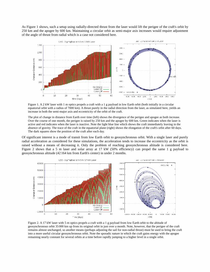
As Figure 1 shows, such a setup using radially-directed thrust from the laser would lift the perigee of the craft's orbit by250 km and the apogee by 600 km. Maintaining a circular orbit as semi-major axis increases would require adjustmentof the angle of thrust from radial which is a case not considered here.
Figure 1. A 2 kW laser with 1 m optics propels a craft with a 1 g payload in low Earth orbit (both initially in a circular equatorial orbit with a radius of 7000 km). A thrust purely in the radial direction from the laser, as simulated here, yields an increase in both the semi-major axis and eccentricity of the orbit of the craft.
The plot of change in distance from Earth over time (left) shows the divergence of the perigee and apogee as both increase. Over the course of one month, the perigee is raised by 250 km and the apogee by 600 km. Green indicates when the laser is active and red indicates when the laser is inactive. Note the light blue line which shows the craft immediately leaving in the absence of gravity. The trace of the craft in the equatorial plane (right) shows the elongation of the craft's orbit after 60 days.The dark squares show the position of the craft after each day.
Of significant interest is a mode of transit from low Earth orbit to geosynchronous orbit. With a single laser and purelyradial acceleration as considered for these simulations, the acceleration tends to increase the eccentricity as the orbit israised without a means of decreasing it. Only the problem of reaching geosynchronous altitude is considered here.Figure 2 shows that a 5 m laser and solar array at 17 kW (50% efficiency) can propel the same 1 g payload togeosynchronous altitude (42 164 km from Earth's center) in under 2 months.
Figure 2. A 17 kW laser with 5 m optics propels a craft with a 1 g payload from low Earth orbit to the altitude of geosynchronous orbit 35 000 km up from its original orbit in just over a month. Note, however, that the perigee of the craft remains almost unchanged, so another means (perhaps adjusting the sail for non-radial thrust) must be used to bring the craftinto a more useful circular geosynchronous orbit. Note the sporadic nature in which the craft gains energy with the apogee remaining nearly constant for several orbits at a time before rapidly jumping to a higher level in a single orbit.

The orbit of the craft does not appear increase uniformly in time, instead following a pattern of little change over severalorbits followed by a significant jump in the apogee of the craft's orbit before repeating. Analysis of the laser and craft'sposition and movement at the time of each jump shows the craft passing the laser at close range at perigee. This indicatesthat the sporadic boosts are a consequence of the laser beam divergence problem which requires the craft to be nearbythe laser for the thrust to be maximized by intercepting the full beam.
The craft is only near the laser's orbit when the craft is near perigee. Thus, if the laser is in that portion of its orbit at thesame time as the craft passes through perigee, the laser is able to provide a large acceleration to the craft causing theobserved jump. Otherwise, if the laser is anywhere else in its orbit, no large acceleration is provided and the craftremains in nearly the same orbit until its next perigee.
Figure 3 shows that as the craft's orbit elongates, acceleration, on average, drops. However, maximum acceleration canstill occur sporadically when the craft reaches perigee with the laser active on the same side of the Earth.
Figure 3. Acceleration of the craft with the same setup as in Figure 2 where a 1 g payload is propelled by a 17 kW laser with5 m optics. Initially, the acceleration by the laser is near maximum as the orbit of the craft is near circular and nearby the laser's orbit at all points. Over time, as the orbit of the craft elongates, the craft is only near the laser's orbit near perigee. When the laser is activated with the craft anywhere else, only a small acceleration is experienced. In the special case when the laser is active while the craft is near perigee, the craft is given a large impulse corresponding to any of the tall spikes in this figure or the rapid jumps in the apogee distance seen in Figure 2.
The chaotic nature of orbital systems suggests that it may be possible to optimize the setup to minimize time of transit,perhaps by deactivating the laser earlier than the current set of conditions require. An optimized system could attempt toforce a resonance to occur between the laser and craft so that the craft is by the laser at every perigee. Constructing suchan optimized system is beyond the scope of this paper but may be of interest as a topic for future analysis.
A less effective but much more straightforward way to optimize the system is to keep the existing set of laser activationconditions but to test the effectiveness for a range of laser powers. For the previous system, computing the time to reachgeosynchronous orbit for powers from 15 kW to 17 kW reveals in Figure 4 a very sensitive relation between transit timeand the power of the laser with numerous maxima and minima. By reducing power from 17 kW to 16.82 kW, the time oftransit is shortened from 38 days to 27 days by as a result of an increased rate of close encounters with the laser despitethe reduction in maximum thrust.

Figure 4. Time of transit (left, dark blue line) to geosynchronous altitude is very sensitive to the levels of laser power (left). Selecting a power of 16.82 kW at one of the many minima (left, blue arrow) yields a solution where the craft passes by the laser at perigee at a greater frequency. This effect is reflected in the increased frequency of jumps in apogee distance permitting the craft to reach higher orbits more rapidly (right) than in Figure 2. Further reductions in transit time are likely possible by varying the power of the laser with time.
The approach speed (left, light blue) is defined as the speed of the craft at the moment it arrives at geosynchronous altitude
relative to a satellite in a circular orbit around the Earth at that altitude. This speed gives the Δ v needed to bring the craft from its laser-propelled trajectory into the circular orbit.
With even larger lasers, the time of transit to geosynchronous altitude becomes even more sensitive to the systemparameters. The sensitivity is a consequence of the craft being propelled to higher altitudes more rapidly which yields inreduction in the number of orbits before reaching the target altitude. With fewer orbits, the fraction of orbits where thecraft experiences a jump is likely to experience more variation across of a range of input parameters and thus show moresensitivity to input parameters.
A 10 m laser and solar array at 50% efficiency can produce a beam of ~70 kW power. Using the same initial conditions,such a system takes 6.7 days to propel a 1 g craft to geosynchronous altitude. As shown in Figure 5, by reducing thepower to 62.1 kW, the transit time drops by more than half to just 2.4 days.
Figure 5. A 10 m laser and solar array at 50% efficiency can generate a beam of ~70 kW power. With the initial conditions used for these simulations, reducing the laser power to 62.1 kW (left, blue arrow) reduces the time to geosynchronous altitude from 6.7 days to 2.4 days. The distance vs. time plot for the 62.1 kW case (right) shows large jumps corresponding to laser activity (green) immediately following perigee (the minima) for a large fraction of the craft's orbits.

As a reminder, the actual numbers from these simulations shown here are for a very specific set of initial conditions witha precise set of assumptions and approximations. The sensitivity of results to inputs implies that actual results for anunoptimized system could vary dramatically if only a few orbits are considered for even small changes in parameterssuch as laser start time, direction of thrust, the size of the sail and even the shape of the sail, many of which cannot beknown with sufficient precision ahead of time. A real system with targeting capabilities would use feedback on the craft'sposition while in transit, permitting adjustments to ensure the craft remains near any of a wide range of possible targettrajectories.
3.2 Interplanetary transit
Beginning with an array size of at least 20 m at 50% efficiency, it becomes possible to propel a small 1 g craft past theMoon and out of Earth orbit in just 4 days but at relatively low speeds of < 5 m/s. As the destination of interplanetarytransportation is generally far beyond the Moon, the speed at which the craft passes lunar orbit, exiting the Earth-Moonsystem, is often of greater significance than time taken to reach lunar orbit itself.
Figure 6 shows that elapsed time and the speed of the craft at lunar distance vary chaotically with array size in this range.In fact, only for array sizes of over 30 m does an increase in array size reliably correspond to an increase in craft speedthrough lunar orbit.
Figure 6. A 20 m array (~270 kW) is near the minimum needed to propel a craft with a 1 g payload past the orbit of the Moon (1 LD = 384 400 km) into interplanetary space in under a week. Upon leaving Earth orbit, the craft follows a trajectory similar in appearance to that predicted by the gravity-less estimate but with a delay of ~2 days from the spiral out of the Earth's gravitational well (right).
As the destination of interplanetary transportation is generally not the Moon, the speed at which the craft leaves the Earth-Moon system (the “departure speed”) is of greater significance than the time taken by the craft to reach lunar orbit. This speed is closely approximated by the approach speed (left, light blue) to a hypothetical massless satellite in lunar orbit as such a satellite would a minute velocity (~1 km/s) directed roughly perpendicular to the direction of velocity of the craft (outward). There is little correlation between laser array size and departure speed for arrays smaller than ~30 m. For larger arrays, speed increases nearly linearly with array size.
For a larger 100 g payload with a ~10 m sail, a 100 m array (producing ~7 MW power) is needed to propel the craft pastlunar orbit in a similar 4 day timespan. However, the increase in array size allows the beam to create a smaller spot sizeat a given distance. The reduced spot size coupled with a much larger sail implies a longer range of maximumacceleration as seen in Figure 7. As a result, this craft continues to accelerate at the maximum rate even beyond the lunarorbit, allowing it to reach a speed of ~15 km/s after leaving the gravitational influence of the Earth compared to just~1 km/s for the previous case of the 1 g payload.
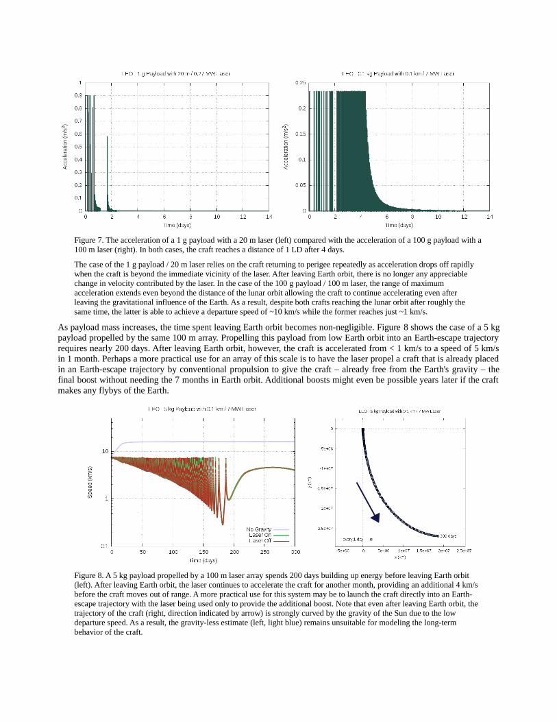
Figure 7. The acceleration of a 1 g payload with a 20 m laser (left) compared with the acceleration of a 100 g payload with a100 m laser (right). In both cases, the craft reaches a distance of 1 LD after 4 days.
The case of the 1 g payload / 20 m laser relies on the craft returning to perigee repeatedly as acceleration drops off rapidly when the craft is beyond the immediate vicinity of the laser. After leaving Earth orbit, there is no longer any appreciable change in velocity contributed by the laser. In the case of the 100 g payload / 100 m laser, the range of maximum acceleration extends even beyond the distance of the lunar orbit allowing the craft to continue accelerating even after leaving the gravitational influence of the Earth. As a result, despite both crafts reaching the lunar orbit after roughly the same time, the latter is able to achieve a departure speed of ~10 km/s while the former reaches just ~1 km/s.
As payload mass increases, the time spent leaving Earth orbit becomes non-negligible. Figure 8 shows the case of a 5 kgpayload propelled by the same 100 m array. Propelling this payload from low Earth orbit into an Earth-escape trajectoryrequires nearly 200 days. After leaving Earth orbit, however, the craft is accelerated from < 1 km/s to a speed of 5 km/sin 1 month. Perhaps a more practical use for an array of this scale is to have the laser propel a craft that is already placedin an Earth-escape trajectory by conventional propulsion to give the craft – already free from the Earth's gravity – thefinal boost without needing the 7 months in Earth orbit. Additional boosts might even be possible years later if the craftmakes any flybys of the Earth.
Figure 8. A 5 kg payload propelled by a 100 m laser array spends 200 days building up energy before leaving Earth orbit (left). After leaving Earth orbit, the laser continues to accelerate the craft for another month, providing an additional 4 km/s before the craft moves out of range. A more practical use for this system may be to launch the craft directly into an Earth-escape trajectory with the laser being used only to provide the additional boost. Note that even after leaving Earth orbit, the trajectory of the craft (right, direction indicated by arrow) is strongly curved by the gravity of the Sun due to the low departure speed. As a result, the gravity-less estimate (left, light blue) remains unsuitable for modeling the long-term behavior of the craft.

3.3 Extrasolar exploration
Entertaining the possibility of interstellar transportation via laser propulsion demands the consideration of laser arrays onthe truly massive scale of upwards of 1 km in size for even the 1 g payload. Naturally, arrays of such scale are notanticipated for the near future in the next few decades. Nonetheless, in the absence of plausible alternatives, thepossibility remains one worth entertaining. A roadmap toward the future development of such systems for interstellarspaceflight has been developed and is discussed in [8].
A 1 km / 700 MW array initially accelerates a craft with a 1 g payload at 2300 m/s2. This acceleration is far above thegravitational acceleration anywhere in the solar system. As a result, the full simulations deviate minimally from thegravity-less “No Earth” estimates.
Using the same initial conditions as before, the craft is rapidly propelled to 2000 km/s (420 au/yr) in the 17 minutesbefore the laser deactivates from entry into Earth's shadow as shown in Figure 9. At this speed, a craft could be directedto reach Neptune (~30 au) in just 9 months, or Proxima (~4.2 ly), the nearest star to the Sun, in 630 years.
Figure 9. A 1 km / 700 MW laser array accelerates a craft with a 1 g payload to 2000 km/s (420 au/yr) in 17 minutes.
Left: A maximum acceleration of 2300 m/s2 occurs for the first 680 seconds before the spot grows larger than the sail and overflows, causing acceleration to rapidly drop. At 1040 seconds, acceleration falls to zero when the laser deactivates after entering Earth's shadow.
Right: The velocity of the craft closely follows the gravity-less estimate as the acceleration from the laser far exceeds any gravitational acceleration found in the solar system. The only major deviation from the estimate occurs from the deactivation of the laser which is not accounted for in the estimate.
A much larger array is needed for interstellar exploration in a reasonable amount of time. A 10 km array can propel thesame 1 g payload to 64 000 km/s, or 0.21c. At this speed, the craft could pass Neptune in just 1 day and Proxima in20 years, a much more reasonable duration for a mission.
Figure 10 shows the speed the craft attains after 1 au (light blue) as a function of array size (left) and payload mass(right). For a 1 g payload, craft speed scales smoothly with a constant power (~1.5) of array size. For a 10 km array, craftspeed varies less smoothly with payload mass with no obvious functional fit from 0.01 g to 10 kg although a negativecorrelation is clear. With a 1 kg payload, the speed from the 10 km drops to just 4000 km/s which, while extremely fastin the context of the solar system and current propulsion systems, remains too slow for exploration of systems beyond.While a laser-propelled gram-class interstellar mission remains a possibility for the distant future, anything much largerwould, at best, be relegated to exploring the outer reaches of our own solar system.
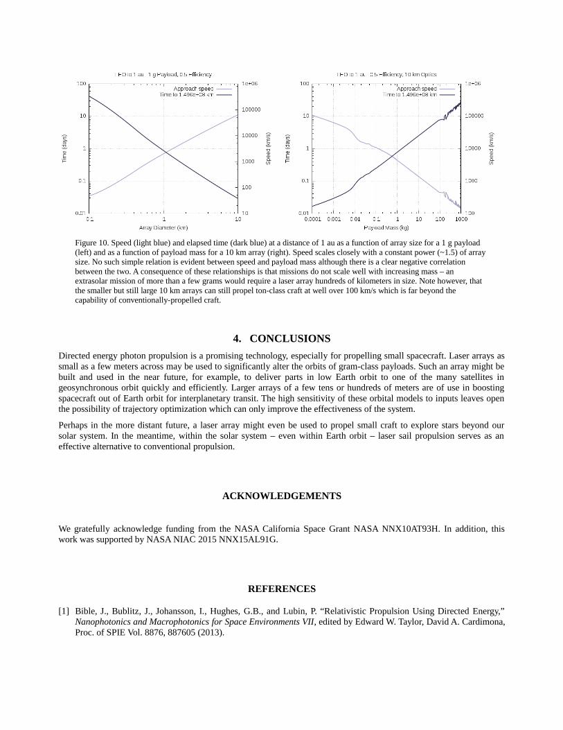
Figure 10. Speed (light blue) and elapsed time (dark blue) at a distance of 1 au as a function of array size for a 1 g payload (left) and as a function of payload mass for a 10 km array (right). Speed scales closely with a constant power (~1.5) of array size. No such simple relation is evident between speed and payload mass although there is a clear negative correlation between the two. A consequence of these relationships is that missions do not scale well with increasing mass – an extrasolar mission of more than a few grams would require a laser array hundreds of kilometers in size. Note however, that the smaller but still large 10 km arrays can still propel ton-class craft at well over 100 km/s which is far beyond the capability of conventionally-propelled craft.
4. CONCLUSIONS
Directed energy photon propulsion is a promising technology, especially for propelling small spacecraft. Laser arrays assmall as a few meters across may be used to significantly alter the orbits of gram-class payloads. Such an array might bebuilt and used in the near future, for example, to deliver parts in low Earth orbit to one of the many satellites ingeosynchronous orbit quickly and efficiently. Larger arrays of a few tens or hundreds of meters are of use in boostingspacecraft out of Earth orbit for interplanetary transit. The high sensitivity of these orbital models to inputs leaves openthe possibility of trajectory optimization which can only improve the effectiveness of the system.
Perhaps in the more distant future, a laser array might even be used to propel small craft to explore stars beyond oursolar system. In the meantime, within the solar system – even within Earth orbit – laser sail propulsion serves as aneffective alternative to conventional propulsion.
ACKNOWLEDGEMENTS
We gratefully acknowledge funding from the NASA California Space Grant NASA NNX10AT93H. In addition, thiswork was supported by NASA NIAC 2015 NNX15AL91G.
REFERENCES
[1] Bible, J., Bublitz, J., Johansson, I., Hughes, G.B., and Lubin, P. “Relativistic Propulsion Using Directed Energy,”Nanophotonics and Macrophotonics for Space Environments VII, edited by Edward W. Taylor, David A. Cardimona,Proc. of SPIE Vol. 8876, 887605 (2013).

[2] Bae, Young K. “Prospective of photon propulsion for interstellar flight.” Physics Procedia 38, 253-279 (2012).[3] Semyonov, Oleg G. “Relativistic rocket: Dream and reality.” Acta Astronautica 99, 52-70 (2014).[4] Hsiao, Fu-Yuen, et al. “Trajectory of spacecraft with photonic laser propulsion in the two-body problem.” Acta
Astronautica 84, 215-226 (2013).[5] Moisson, X., Bretagnon, P., “Analytical Planetary solution VSOP2000,” Celestial Mechanics and Dynamical
Astronomy 80 (3), 205-213 (2001).[6] Dormand, J., Prince, P., “A family of embedded Runge-Kutta formulae,” Journal of Computational and Applied
Mathematics 6 (1), 19-26 (1980).[7] Lubin, P.M., Hughes, G.B., Bible, J. and Johannson, I. “Directed Energy for Planetary Defense and Exploration -
Applications to Relativistic Propulsion and Interstellar and Intergalactic Communications”, Journal of the BritishInterplanetary Society (2015).
[8] Lubin, P., “A Roadmap to Interstellar Flight,” Journal of the British Interplanetary Society (2015).