Optyma control AK-RC 113 three phase
20
User Guide Optyma™ control AK-RC 113 three phase
Transcript of Optyma control AK-RC 113 three phase

User Guide
Optyma™ control AK-RC 113 three phase
User Guide | Optyma™ control AK-RC 113 three phase
2 | BC317523579312en-000101 © Danfoss | DCS (vt) | 2020.03
Contents 1.0 Introduction 1.1 General .................................................................................................................................................................3
2.0 Technical Characteristics 2.1 Product ID Codes..............................................................................................................................................3 2.2 Product Series – Technical Characteristics ..............................................................................................3 2.3 Overall dimension ............................................................................................................................................4 2.4 Identification Data ...........................................................................................................................................4 2.5 Transport and Storage ....................................................................................................................................4
3.0 Functionality 3.1 Functions managed by the AK-RC 113 electrical panel .....................................................................4
4.0 Installation 4.1 Standard equipment for assembly and use ...........................................................................................5 4.2 Mechanical assembly of the panel ............................................................................................................5 4.3 Electrical wirings ..............................................................................................................................................6 4.4 Connection of the front panel .....................................................................................................................7 4.5 Pre-use checks ...................................................................................................................................................7 4.6 Compressor motor circuit breaker calibration ......................................................................................8 4.7 Closing the electrical panel ..........................................................................................................................8
5.0 Parameter programming 5.1 Control panel .....................................................................................................................................................9 5.2 Front keypad ......................................................................................................................................................9 5.3 LED display .........................................................................................................................................................9 5.4 General .............................................................................................................................................................. 10 5.5 Key to symbols ............................................................................................................................................... 10 5.6 Setting and displaying the set points .................................................................................................... 10 5.7 Level 1 programming (user level)............................................................................................................ 10 5.8 List of Level 1 variables (user level) ......................................................................................................... 11 5.9 Level 2 programming (installer level) .................................................................................................... 11 5.10 List of Level 2 variables (installer level) ................................................................................................. 11 5.11 Switching on the AK-RC 113 electronic controller ............................................................................ 14 5.12 Cold/hot activation/deactivation conditions ..................................................................................... 14 5.13 Manual defrost activation / deactivation ............................................................................................. 14 5.14 Defrost with thermostated resistances ................................................................................................. 14 5.15 Hot gas defrost ............................................................................................................................................... 14 5.16 Pump down function ................................................................................................................................... 14 5.17 Password function ........................................................................................................................................ 14
6.0 Modbus connection 6.1 Net configuration with modbus-RTU protocol .................................................................................. 15
7.0 Diagnostics 7.1 Diagnostics by means of alarm codes ................................................................................................... 15 7.2 Troubleshooting ............................................................................................................................................ 16
8.0 Maintenance 8.1 General safety rules ...................................................................................................................................... 17 8.2 Maintenance ................................................................................................................................................... 17
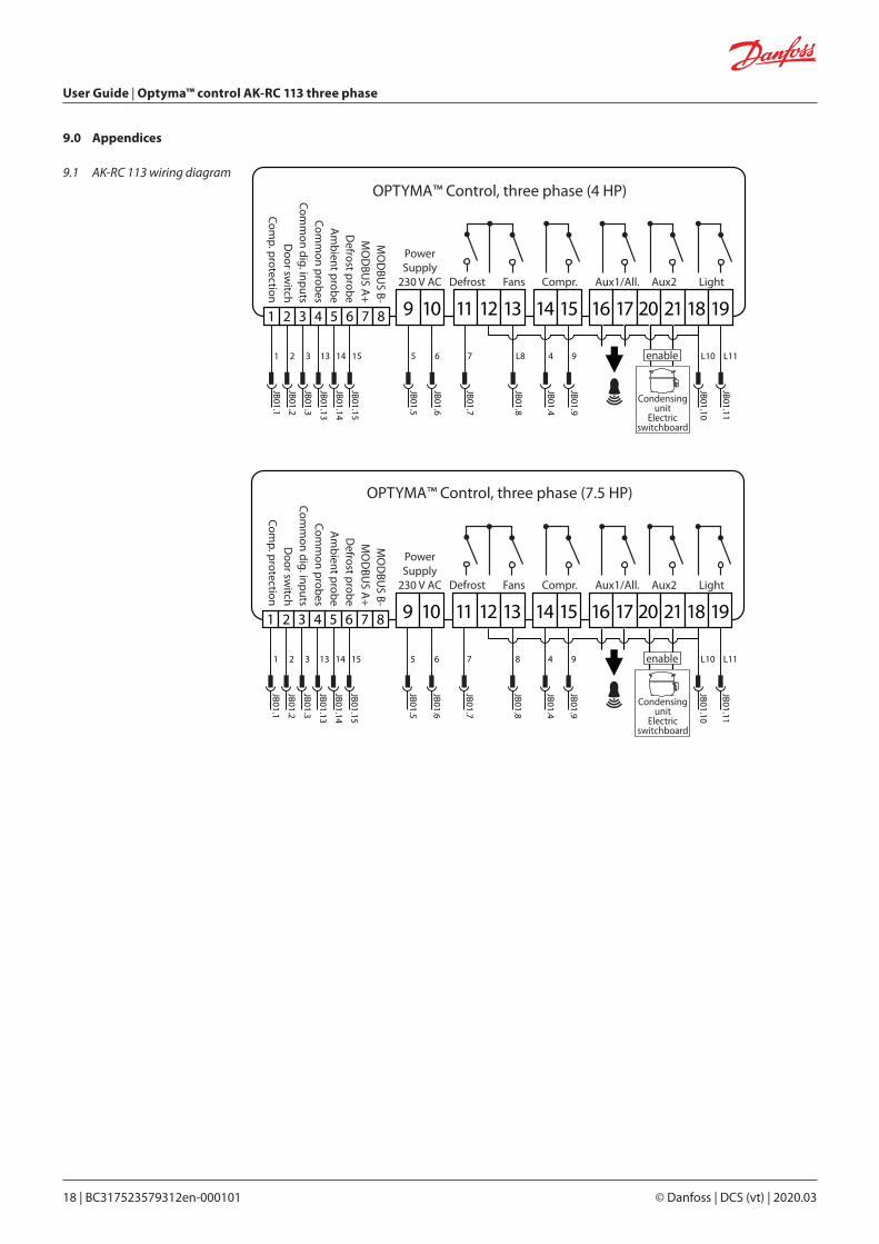
9.0 Appendices 9.1 AK-RC 113 wiring diagram ......................................................................................................................... 18 9.2 Part List ............................................................................................................................................................. 19
10.0 Ordering ....................................................................................................................................................................... 19
User Guide | Optyma™ control AK-RC 113 three phase
© Danfoss | DCS (vt) | 2020.03 BC317523579312en-000101 | 3
1.0 Introduction
1.1 General The OPTYMA™ Control three-phase is a controller for refrigeration systems with a three-phase compressor or for controlling the three-phase evaporating unit only, for complete cold room management. Front access to the automatic fuse and motor protector for the compressor and an innovative design combine to make it the ideal choice for effective refrigeration control.
Applications:• Complete management of three-phase refrigerating systems up to 7.5 HP static or ventilated, with
off-cycle or electrical defrosting.
2.0 Technical Characteristics
2.1 Product ID Codes Line of electrical panel of OPTYMATM Control (4 HP):
Line of electrical panel of OPTYMATM Control (7 HP):
Code Numbers
Identification codes Compressor motor circuit breaker range
080Z3221 4,5 – 6,3 A
080Z3222 7 – 10 A
Code Numbers
Identification codes Compressor motor circuit breaker range
080Z3226 11 – 16 A
080Z3227 14 – 20 A
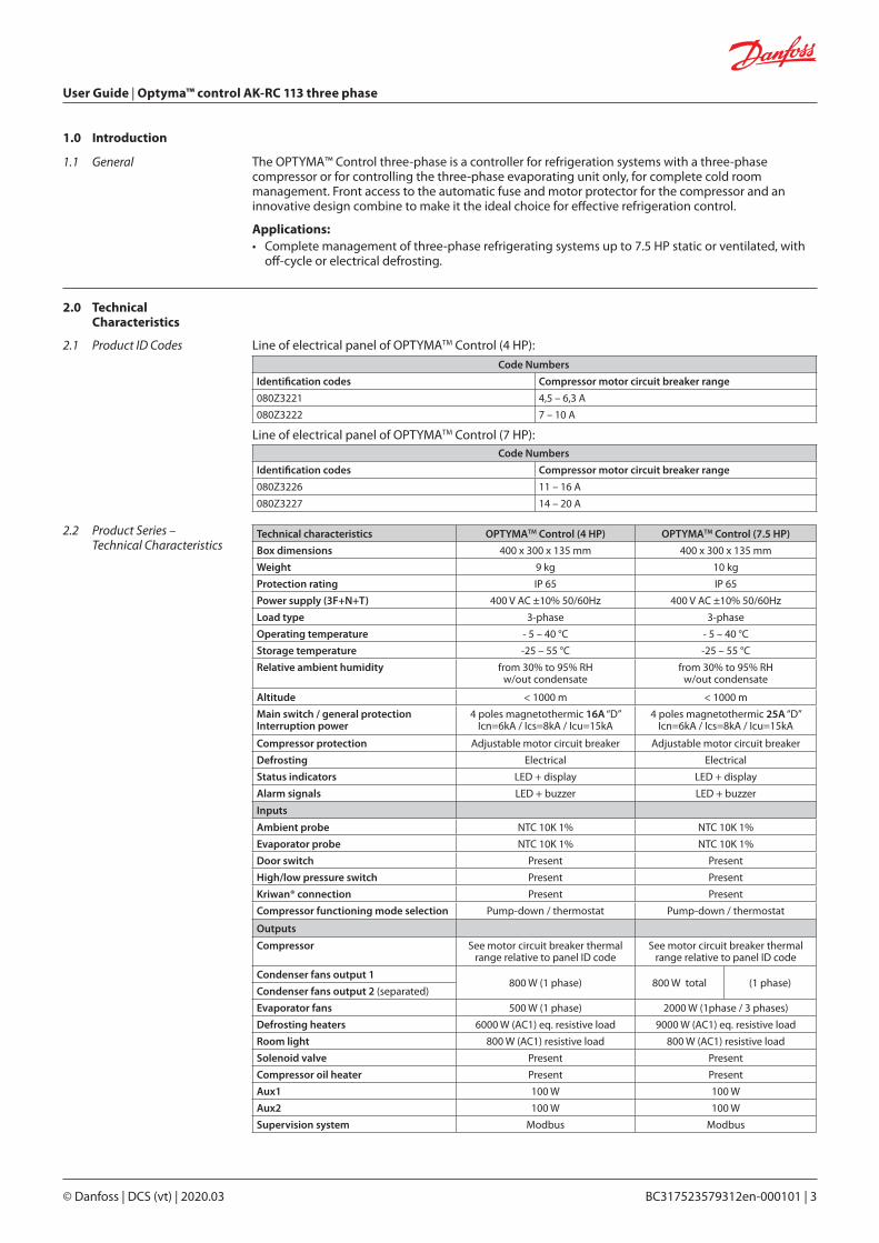
2.2 Product Series – Technical Characteristics
Technical characteristics OPTYMATM Control (4 HP) OPTYMATM Control (7.5 HP)
Box dimensions 400 x 300 x 135 mm 400 x 300 x 135 mm
Weight 9 kg 10 kg
Protection rating IP 65 IP 65
Power supply (3F+N+T) 400 V AC ±10% 50/60Hz 400 V AC ±10% 50/60Hz
Load type 3-phase 3-phase
Operating temperature - 5 – 40 °C - 5 – 40 °C
Storage temperature -25 – 55 °C -25 – 55 °C
Relative ambient humidity from 30% to 95% RH w/out condensate
from 30% to 95% RHw/out condensate
Altitude < 1000 m < 1000 m
Main switch / general protectionInterruption power
4 poles magnetothermic 16A “D”Icn=6kA / Ics=8kA / Icu=15kA
4 poles magnetothermic 25A “D”Icn=6kA / Ics=8kA / Icu=15kA
Compressor protection Adjustable motor circuit breaker Adjustable motor circuit breaker
Defrosting Electrical Electrical
Status indicators LED + display LED + display
Alarm signals LED + buzzer LED + buzzer
Inputs
Ambient probe NTC 10K 1% NTC 10K 1%
Evaporator probe NTC 10K 1% NTC 10K 1%
Door switch Present Present
High/low pressure switch Present Present
Kriwan® connection Present Present
Compressor functioning mode selection Pump-down / thermostat Pump-down / thermostat
Outputs
Compressor See motor circuit breaker thermal range relative to panel ID code
See motor circuit breaker thermal range relative to panel ID code
Condenser fans output 1800 W (1 phase) 800 W total (1 phase)
Condenser fans output 2 (separated)
Evaporator fans 500 W (1 phase) 2000 W (1phase / 3 phases)
Defrosting heaters 6000 W (AC1) eq. resistive load 9000 W (AC1) eq. resistive load
Room light 800 W (AC1) resistive load 800 W (AC1) resistive load
Solenoid valve Present Present
Compressor oil heater Present Present
Aux1 100 W 100 W
Aux2 100 W 100 W
Supervision system Modbus Modbus
User Guide | Optyma™ control AK-RC 113 three phase
4 | BC317523579312en-000101 © Danfoss | DCS (vt) | 2020.03
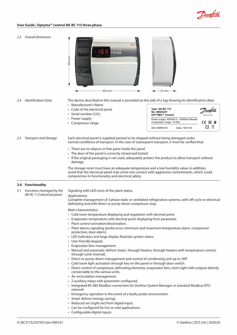
2.3 Overall dimension
2.4 Identification Data
2.5 Transport and Storage
400 mm 135 mm
300
mm
The device described in this manual is provided on the side of a tag showing its identification data:• Manufacturer's Name• Code of the electrical panel• Serial number (S.N.)• Power supply• Compressor range
Each electrical panel is supplied packed to be shipped without being damaged undernormal conditions of transport. In the case of subsequent transport, it must be verified that:
• There are no objects or free parts inside the panel• The door of the panel is correctly closed and locked• If the original packaging is not used, adequately protect the product to allow transport without
damage.
The storage room must have an adequate temperature and a low humidity value; in addition, avoid that the electrical panel may come into contact with aggressive contaminants, which could compromise its functionality and electrical safety.
Type: AK-RC 113No: 080Z3227OPTYMA™ Control
Power supply: 400VAC/3 - 50/60Hz+NeutralCompressor range: 14-20A
MADE IN ITALY
S/N: 080R0100 Date: 19/01/18
3.0 Functionality
3.1 Functions managed by the AK-RC 113 electrical panel
Signaling with LED icons of the plant status.
Applications: Complete management of 3 phase static or ventilated refrigeration systems, with off-cycle or electrical defrosting and with direct or pump-down compressor stop.
Main characteristics:• Cold room temperature displaying and regulation with decimal point.• Evaporator temperature with decimal point displaying from parameter. • Plant control activation/deactivation. • Plant alarms signaling (probe error, minimum and maximum temperature alarm, compressor
protection, door alarm). • LED indicators and large display illustrate system status. • User-friendly keypad. • Evaporator fans management. • Manual and automatic defrost (static, through heaters, through heaters with temperature control,
through cycle reversal). • Direct or pump-down management and control of condensing unit up to 2HP. • Cold room light activation through key on the panel or through door-switch. • Direct control of compressor, defrosting elements, evaporator fans, room light with outputs directly
connectable to the various units. • Air recirculation management. • 2 auxiliary relays with parameter-configured. • Integrated RS-485 Modbus connection for Danfoss System Manager or standard Modbus-RTU
network • Emergency operation in the event of a faulty probe environment. • Smart defrost (energy saving). • Reduced set (night set) from digital input. • Can be configured for hot or cold applications. • Configurable digital inputs.
User Guide | Optyma™ control AK-RC 113 three phase
© Danfoss | DCS (vt) | 2020.03 BC317523579312en-000101 | 5
4.0 Installation
The AK-RC 113 electrical panel, for assembly and use, is equipped with:
• Nr 4 sealing gaskets, to be placed between the fixing screw and the back of the box• Nr 1 use and maintenance manual• Nr 1 wiring diagram• Nr 1 drilling layout• Nr 2 NTC probes 10K 1%
• Each panel is designed for wall mounting; choose an appropriate fixing system, depending on the weight of the panel and the type of support on which it will be fixed.
• Install the panel in places that respect its IP rating.
• Keep the IP protection level of the appliance intact by properly assembling the cable glands and/or the pipe clamps with appropriate characteristics.
• Install the panel at a height that allows the operator an easy use and internal access. The operator should not come to be in a dangerous situation when he is working on the panel. The height must however be between 0.6 and 1.7 meters from the floor.
• Install the electrical panel in an area away from sources of heat and possibly protected from atmospheric agents.
4.1 Standard equipment for assembly and use
4.2 Mechanical assembly of the panel
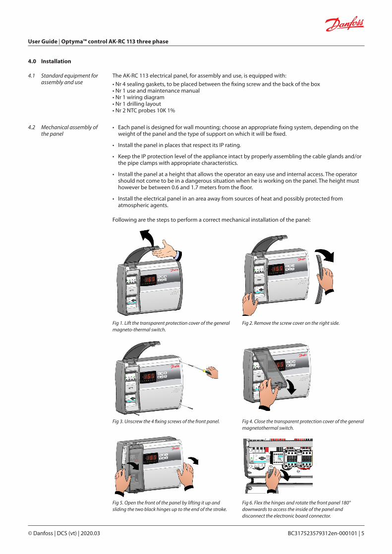
Following are the steps to perform a correct mechanical installation of the panel:
Fig 1. Lift the transparent protection cover of the general magneto-thermal switch.
Fig 3. Unscrew the 4 fixing screws of the front panel.
Fig 5. Open the front of the panel by lifting it up and sliding the two black hinges up to the end of the stroke.
Fig 2. Remove the screw cover on the right side.
Fig 4. Close the transparent protection cover of the general magnetothermal switch.
Fig 6. Flex the hinges and rotate the front panel 180° downwards to access the inside of the panel and disconnect the electronic board connector.

User Guide | Optyma™ control AK-RC 113 three phase
6 | BC317523579312en-000101 © Danfoss | DCS (vt) | 2020.03
• For electrical connections, refer to the specific wiring diagram and to the technical characteristics of the panel model to be installed.
• The power supply to the panel must be carried out exclusively with a dedicated line, upstream of which a device suitable for protection against indirect contacts (differential switch) must be installed.
• Avoid putting power cables and signal cables (probes and digital inputs) in the same conduits (or pipes).
• Avoid using multipolar cables in which there are conductors connected to inductive and power loads and signal conductors such as probes and digital inputs.
• Reduce the lengths of the connecting cables as much as possible, preventing the wiring from taking the spiral shape that is harmful to possible inductive effects on the electronics.
• If it’s necessary to extend the probes, conductors must be used with a suitable section and in any case not less than 1 mm2.
4.3 Electrical wirings
Fig 7. Apply pressure on the sides of each individual hinge to remove it from its seat and completely remove the front panel.
Fig 9. Using the supplied drilling layout, make the four fixing holes on the wall.
Fig 11. Now make the electrical connections as indicated in the following chapter.
Fig 8. Using a screwdriver, press the four pre-set holes on the back to make the four fixing holes of the electrical panel.
Fig 10. Using the four holes made previously, fix the back of the box using four screws of adequate length in relation to the thickness of the wall. Place a rubber washer (supplied) between each fastening screw and the back of the box.
User Guide | Optyma™ control AK-RC 113 three phase
© Danfoss | DCS (vt) | 2020.03 BC317523579312en-000101 | 7
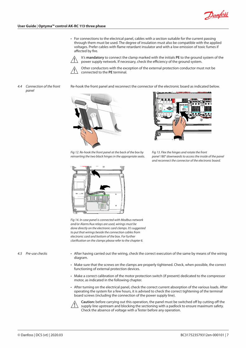
4.4 Connection of the front panel
4.5 Pre-use checks
• For connections to the electrical panel, cables with a section suitable for the current passing through them must be used. The degree of insulation must also be compatible with the applied voltages. Prefer cables with flame retardant insulator and with a low emission of toxic fumes if affected by fire.
It’s mandatory to connect the clamp marked with the initials PE to the ground system of the power supply network. If necessary, check the efficiency of the ground system.
Other conductors with the exception of the external protection conductor must not be connected to the PE terminal.
• After having carried out the wiring, check the correct execution of the same by means of the wiring diagram.
• Make sure that the screws on the clamps are properly tightened. Check, when possible, the correct functioning of external protection devices.
• Make a correct calibration of the motor protection switch (if present) dedicated to the compressor motor, as indicated in the following chapter.
• After turning on the electrical panel, check the correct current absorption of the various loads. After operating the system for a few hours, it is advised to check the correct tightening of the terminal board screws (including the connection of the power supply line).
Caution: before carrying out this operation, the panel must be switched off by cutting off the supply line upstream and blocking the sectioning with a padlock to ensure maximum safety. Check the absence of voltage with a Tester before any operation.
Re-hook the front panel and reconnect the connector of the electronic board as indicated below.
Fig 12. Re-hook the front panel at the back of the box by reinserting the two black hinges in the appropriate seats.
Fig 14. In case panel is connected with Modbus network and/or Alarm/Aux relays are used, wirings must bedone directly on the electronic card clamps. It’s suggested to put that wirings beside the connection cables from electronic card and bottom of the box. For further clarification on the clamps please refer to the chapter 6.
Fig 13. Flex the hinges and rotate the frontpanel 180° downwards to access the inside of the panel and reconnect the connector of the electronic board.
User Guide | Optyma™ control AK-RC 113 three phase
8 | BC317523579312en-000101 © Danfoss | DCS (vt) | 2020.03
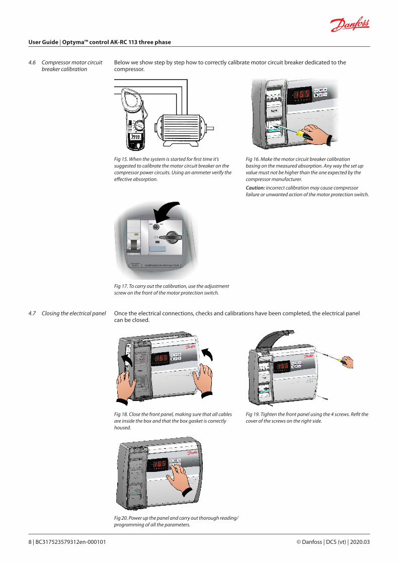
4.6 Compressor motor circuit breaker calibration
4.7 Closing the electrical panel
Below we show step by step how to correctly calibrate motor circuit breaker dedicated to the compressor.
Once the electrical connections, checks and calibrations have been completed, the electrical panel can be closed.
Fig 15. When the system is started for first time it’s suggested to calibrate the motor circuit breaker on thecompressor power circuits. Using an ammeter verify the effective absorption.
Fig 18. Close the front panel, making sure that all cables are inside the box and that the box gasket is correctly housed.
Fig 20. Power up the panel and carry out thorough reading/ programming of all the parameters.
Fig 17. To carry out the calibration, use the adjustment screw on the front of the motor protection switch.
Fig 16. Make the motor circuit breaker calibration basing on the measured absorption. Any way the set up value must not be higher than the one expected by the compressor manufacturer.
Caution: incorrect calibration may cause compressor failure or unwanted action of the motor protection switch.
Fig 19. Tighten the front panel using the 4 screws. Refit the cover of the screws on the right side.
User Guide | Optyma™ control AK-RC 113 three phase
© Danfoss | DCS (vt) | 2020.03 BC317523579312en-000101 | 9
5.0 Parameter programming
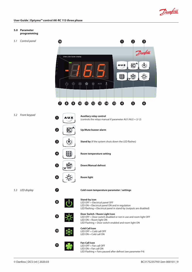
5.1 Control panel
5.2 Front keypad
116
487 9 10 11 12 13 14 15
2
5
3
6
Auxiliary relay control(controls the relays manual if parameter AU1/AU2 = 2/-2)
1
Up/Mute buzzer alarm2
Stand by (if the system shuts down the LED flashes)3
Room temperature setting4
Down/Manual defrost5
Room light6
5.3 LED display Cold room temperature parameter / settings7
Stand-by iconLED OFF = Electrical panel OFFLED ON = Electrical panel ON and in regulationLED flashing = Electrical panel in stand-by (outputs are disabled)
Door Switch / Room Light IconLED OFF = Door switch disabled or not in use and room light OFFLED ON = Room light ONLED Flashing = Door switch enabled and room light ON
Cold Call IconLED OFF = Cold call OFFLED ON = Cold call ON
Fan Call IconLED OFF = Fan call OFFLED ON = Fan call ONLED Flashing = Fans paused after defrost (see parameter F4)
8
9
10
11
User Guide | Optyma™ control AK-RC 113 three phase
10 | BC317523579312en-000101 © Danfoss | DCS (vt) | 2020.03
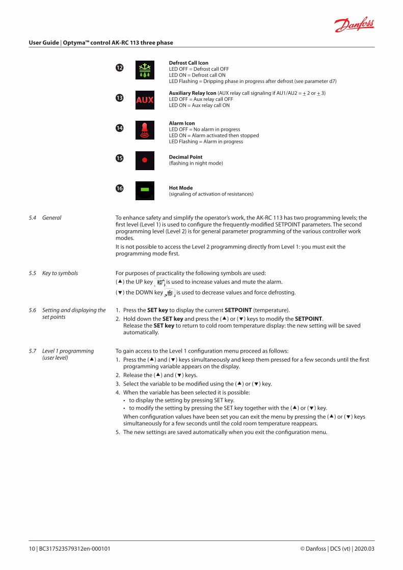
Defrost Call IconLED OFF = Defrost call OFFLED ON = Defrost call ONLED Flashing = Dripping phase in progress after defrost (see parameter d7)
Auxiliary Relay Icon (AUX relay call signaling if AU1/AU2 = + 2 or + 3)LED OFF = Aux relay call OFFLED ON = Aux relay call ON
Alarm IconLED OFF = No alarm in progressLED ON = Alarm activated then stoppedLED Flashing = Alarm in progress
Decimal Point(flashing in night mode)
Hot Mode(signaling of activation of resistances)
12
13
14
15
16
To enhance safety and simplify the operator’s work, the AK-RC 113 has two programming levels; the first level (Level 1) is used to configure the frequently-modified SETPOINT parameters. The second programming level (Level 2) is for general parameter programming of the various controller work modes.
It is not possible to access the Level 2 programming directly from Level 1: you must exit the programming mode first.
For purposes of practicality the following symbols are used:
() the UP key is used to increase values and mute the alarm.
() the DOWN key is used to decrease values and force defrosting.
5.4 General
5.5 Key to symbols
5.6 Setting and displaying the set points
1. Press the SET key to display the current SETPOINT (temperature).
2. Hold down the SET key and press the () or () keys to modify the SETPOINT. Release the SET key to return to cold room temperature display: the new setting will be saved
automatically.
5.7 Level 1 programming (user level)
To gain access to the Level 1 configuration menu proceed as follows:
1. Press the () and () keys simultaneously and keep them pressed for a few seconds until the first programming variable appears on the display.
2. Release the () and () keys.
3. Select the variable to be modified using the () or () key.
4. When the variable has been selected it is possible:• to display the setting by pressing SET key.• to modify the setting by pressing the SET key together with the () or () key.
When configuration values have been set you can exit the menu by pressing the () or () keys simultaneously for a few seconds until the cold room temperature reappears.
5. The new settings are saved automatically when you exit the configuration menu.
User Guide | Optyma™ control AK-RC 113 three phase
© Danfoss | DCS (vt) | 2020.03 BC317523579312en-000101 | 11
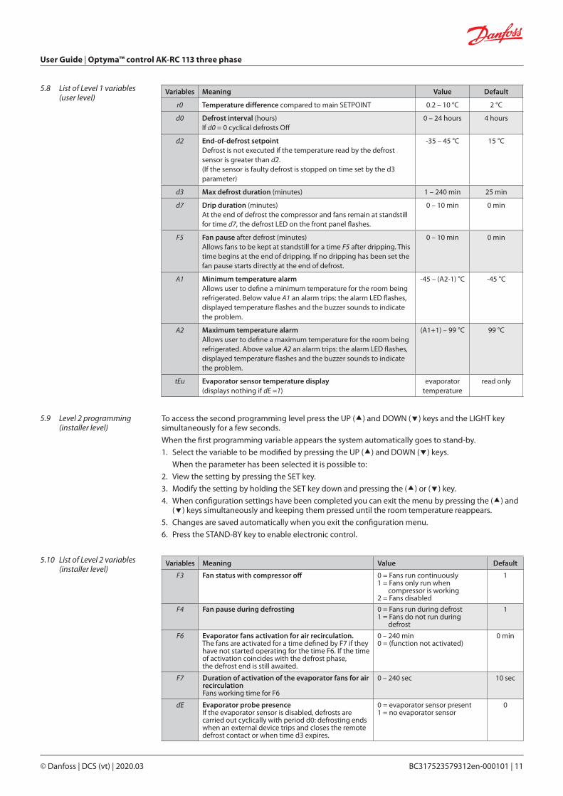
5.8 List of Level 1 variables (user level)
To access the second programming level press the UP () and DOWN () keys and the LIGHT key simultaneously for a few seconds.
When the first programming variable appears the system automatically goes to stand-by.
1. Select the variable to be modified by pressing the UP () and DOWN () keys.
When the parameter has been selected it is possible to:
2. View the setting by pressing the SET key.
3. Modify the setting by holding the SET key down and pressing the () or () key.
4. When configuration settings have been completed you can exit the menu by pressing the () and () keys simultaneously and keeping them pressed until the room temperature reappears.
5. Changes are saved automatically when you exit the configuration menu.
6. Press the STAND-BY key to enable electronic control.
5.9 Level 2 programming (installer level)
5.10 List of Level 2 variables (installer level)
Variables Meaning Value Default
F3 Fan status with compressor off 0 = Fans run continuously 1 = Fans only run when
compressor is working 2 = Fans disabled
1
F4 Fan pause during defrosting 0 = Fans run during defrost1 = Fans do not run during
defrost
1
F6 Evaporator fans activation for air recirculation.The fans are activated for a time defined by F7 if they have not started operating for the time F6. If the time of activation coincides with the defrost phase,the defrost end is still awaited.
0 – 240 min0 = (function not activated)
0 min
F7 Duration of activation of the evaporator fans for air recirculationFans working time for F6
0 – 240 sec 10 sec
dE Evaporator probe presenceIf the evaporator sensor is disabled, defrosts are carried out cyclically with period d0: defrosting ends when an external device trips and closes the remote defrost contact or when time d3 expires.
0 = evaporator sensor present1 = no evaporator sensor
0
Variables Meaning Value Default
r0 Temperature difference compared to main SETPOINT 0.2 – 10 °C 2 °C
d0 Defrost interval (hours)If d0 = 0 cyclical defrosts Off
0 – 24 hours 4 hours
d2 End-of-defrost setpointDefrost is not executed if the temperature read by the defrost sensor is greater than d2.(If the sensor is faulty defrost is stopped on time set by the d3 parameter)
-35 – 45 °C 15 °C
d3 Max defrost duration (minutes) 1 – 240 min 25 min
d7 Drip duration (minutes)At the end of defrost the compressor and fans remain at standstill for time d7, the defrost LED on the front panel flashes.
0 – 10 min 0 min
F5 Fan pause after defrost (minutes)Allows fans to be kept at standstill for a time F5 after dripping. This time begins at the end of dripping. If no dripping has been set the fan pause starts directly at the end of defrost.
0 – 10 min 0 min
A1 Minimum temperature alarmAllows user to define a minimum temperature for the room being refrigerated. Below value A1 an alarm trips: the alarm LED flashes, displayed temperature flashes and the buzzer sounds to indicate the problem.
-45 – (A2-1) °C -45 °C
A2 Maximum temperature alarmAllows user to define a maximum temperature for the room being refrigerated. Above value A2 an alarm trips: the alarm LED flashes, displayed temperature flashes and the buzzer sounds to indicate the problem.
(A1+1) – 99 °C 99 °C
tEu Evaporator sensor temperature display (displays nothing if dE =1)
evaporator temperature
read only

User Guide | Optyma™ control AK-RC 113 three phase
12 | BC317523579312en-000101 © Danfoss | DCS (vt) | 2020.03
d1 Defrost type: with heater elements, cycle inversion (hot gas) or with thermostatic resistance.Warning: do not set d1=1 in this type of panel; see Section 5.15.
0 = element1 = hot gas (see section 5.15)2 = with thermostatic resistance
0
dPo Defrost at Power On 0 = disabled1 = defrost at power-on
(if possible)
0
dSE Smart defrost 0 = disabled1 = enabled
0
dSt Smart defrost Setpoint (if dSE=1)The count of the time between defrosts is increased only if the compressor is on and the evaporator temperature is lower than dSt.
-30 – 30 °C 1 °C
dFd Display during defrost 0 = current temperature1 = room temperature at the
beginning of the defrost2 = “DEF”
1
Ad Modbus Network address 0 – 247 0
Bdr Modbus baudrate 0 = 300 baud1 = 600 baud 2 = 1200 baud3 = 2400 baud4 = 4800 baud5 = 9600 baud6 = 14400 baud7 = 19200 baud8 = 38400 baud
8
Prt Modbus parity check 0 = none1 = even2 = odd
1
Ald Minimum and maximum temperaturesignalling and alarm display delay
0 – 240 min 120 min
C1 Minimum time between shutdown and subsequent switching on of the compressor.
0 – 15 min 0 min
CAL Cold room sensor value correction -10 – 10 °C 0 °C
CE1 Compressor ON operating time in the event of a faulty ambient probe.(emergency operation). With CE1=0 the emergency operation in the presence of error E0 remains disabled, the compressor remains off and defrosts are inhibited topreserve the residual cold.
0 – 240 min
0 = disabled
0 min
CE2 Compressor OFF operating time in theevent of a faulty ambient probe.
5 – 240 min 5 min
doC Compressor safety time for door switch:when the door is opened the evaporator fans shut down and the compressor will continue working for time doC, after which it will shut down.
0 – 5 min 0 min
tdo Compressor restart time after door opening. when the door is opened and after tdo time, it’s setted back the normal functioning giving door open alarm (Ed)If the door switch is closed and the light stays on for a longer time than tdo light cell alarm is signaled (E9). With tdo=0 the parameter is disabled.
0 – 240 min
0 = disabled
0 min
Fst FAN shutdown TEMPERATUREThe fans will stop if the temperature value read by the evaporator sensor is higher than this value.
-45 – 99 °C 99 °C
Fd Fst differential 1 – 10 °C 2 °C
LSE Minimum value attributable to setpoint. -45 – (HSE-1) °C -45 °C
HSE Maximum value attributable to setpoint. (LSE+1) – 99 °C 99 °C
User Guide | Optyma™ control AK-RC 113 three phase
© Danfoss | DCS (vt) | 2020.03 BC317523579312en-000101 | 13
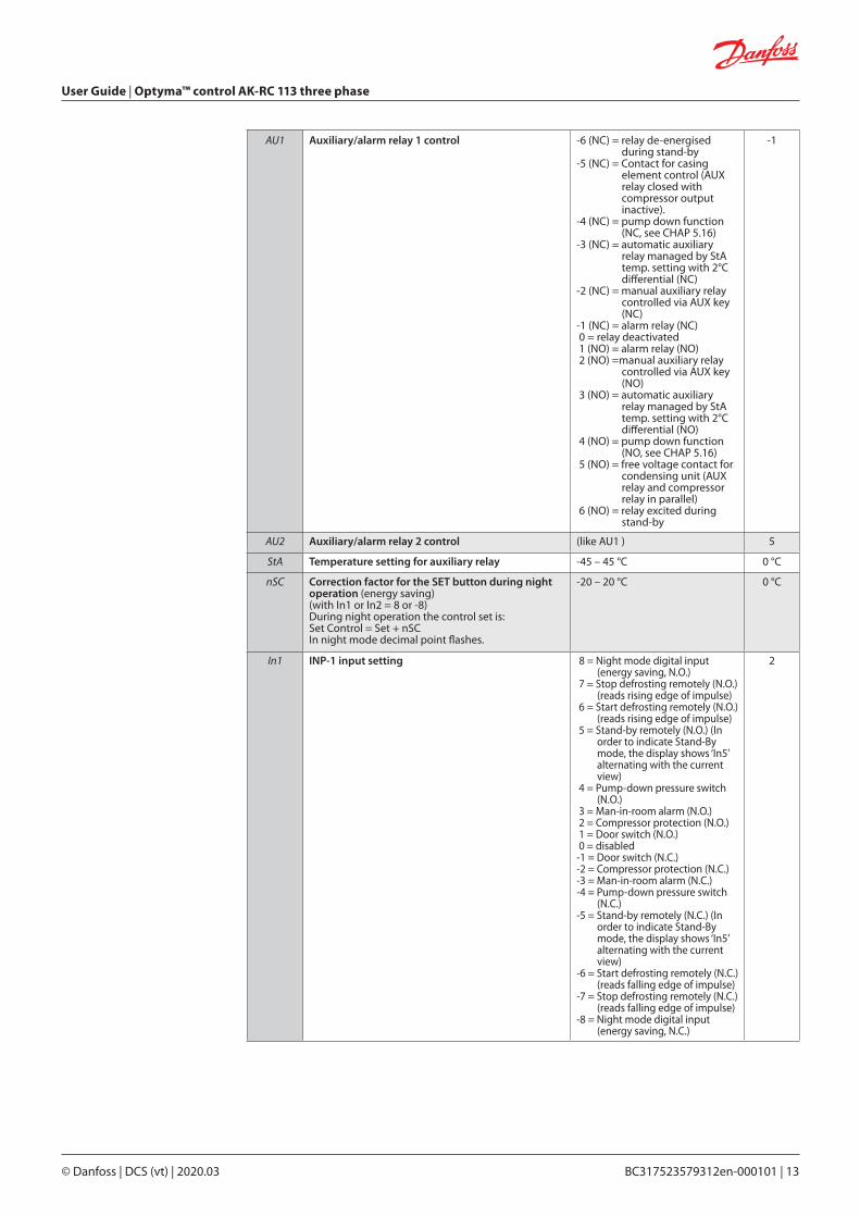
AU1 Auxiliary/alarm relay 1 control -6 (NC) = relay de-energised during stand-by
-5 (NC) = Contact for casing element control (AUX relay closed with compressor output inactive).
-4 (NC) = pump down function (NC, see CHAP 5.16)
-3 (NC) = automatic auxiliary relay managed by StA temp. setting with 2°C differential (NC)
-2 (NC) = manual auxiliary relay controlled via AUX key (NC)
-1 (NC) = alarm relay (NC) 0 = relay deactivated 1 (NO) = alarm relay (NO) 2 (NO) =manual auxiliary relay
controlled via AUX key (NO)
3 (NO) = automatic auxiliary relay managed by StA temp. setting with 2°C differential (NO)
4 (NO) = pump down function (NO, see CHAP 5.16)
5 (NO) = free voltage contact for condensing unit (AUX relay and compressor relay in parallel)
6 (NO) = relay excited during stand-by
-1
AU2 Auxiliary/alarm relay 2 control (like AU1 ) 5
StA Temperature setting for auxiliary relay -45 – 45 °C 0 °C
nSC Correction factor for the SET button during night operation (energy saving)(with In1 or In2 = 8 or -8) During night operation the control set is: Set Control = Set + nSC In night mode decimal point flashes.
-20 – 20 °C 0 °C
In1 INP-1 input setting 8 = Night mode digital input (energy saving, N.O.)
7 = Stop defrosting remotely (N.O.) (reads rising edge of impulse)
6 = Start defrosting remotely (N.O.) (reads rising edge of impulse)
5 = Stand-by remotely (N.O.) (In order to indicate Stand-By mode, the display shows ‘In5’ alternating with the current view)
4 = Pump-down pressure switch (N.O.)
3 = Man-in-room alarm (N.O.) 2 = Compressor protection (N.O.) 1 = Door switch (N.O.) 0 = disabled-1 = Door switch (N.C.)-2 = Compressor protection (N.C.)-3 = Man-in-room alarm (N.C.)-4 = Pump-down pressure switch
(N.C.)-5 = Stand-by remotely (N.C.) (In
order to indicate Stand-By mode, the display shows ‘In5’ alternating with the current view)
-6 = Start defrosting remotely (N.C.) (reads falling edge of impulse)
-7 = Stop defrosting remotely (N.C.) (reads falling edge of impulse)
-8 = Night mode digital input (energy saving, N.C.)
2

User Guide | Optyma™ control AK-RC 113 three phase
14 | BC317523579312en-000101 © Danfoss | DCS (vt) | 2020.03
5.11 Switching on the AK-RC 113 electronic controller
5.12 Cold/hot activation/deactivation conditions
5.13 Manual defrost activation / deactivation
After completing the wiring of the electrical panel, power it by operating the main switch; immediately the electrical panel will emit a sound for a few seconds and at the same time all the LEDs will light up on the display.
In cold mode (mOd=0), the AK-RC 113 controller activates the compressor when cold room temperature exceeds setting + differential (r0); it deactivates the compressor when cold room temperature is lower than the setting.
If Pump-Down function is selected (parameter AU1/AU2 = 4/-4), see chapter 5.16 for compressor activation/deactivation conditions.
In hot mode (mOd=1), the AK-RC 113 controller activates the heat output (COMPR output) when cold room temperature drops below setting-differential (r0); it deactivates the heat output (COMPR output) when cold room temperature is higher than the setting.
To activate the defrost, simply press the dedicated key (see Chapter 5.2) in this way the resistance relay is activated. Defrost is not activated if the set end defrost temperature (d2) is lower than the temperature detected by the evaporator probe. Defrost will end when the end defrost temperature (d2) is reached or for maximum defrost duration (d3) or for manual defrosting end forcing (defrost end button or digital input).
5.14 Defrost with thermostated resistances
5.15 Hot gas defrost
5.16 Pump down function
5.17 Password function
Set the parameter d1=2 for the management of the resistance defrost with time limit. During defrosting, the defrost relay is activated if the temperature read by the defrost probe is less than d2. The defrost phase lasts d3 minutes, regardless of the state of the relay. This allows a better defrosting of the evaporator with a consequent energy saving.
Warning: do not set d1 = 1 in this type of electrical panel.The hot gas defrost is not available for this type of electrical panel.
Selection of PUMP DOWN functioning mode for the compressor working on X1 terminal block, changing the selection connection as indicated in the wiring diagram.
Warning: Parameters AU1 / AU2 must never be set to 4 / -4 because the PUMP DOWN function is made in electromechanical inside the electrical panel.
When parameter PA is setting with value different to 0 the protection function is activated.See parameter P1 for the different protection.When PA is setting the protection start after two minutes of inactivity. On display appear 000.With up/down modify the number, with set key confirm it.Use universal number 100 if you don’t remember the password.
In2 INP-2 input setting (like In1) 1
bEE Buzzer enable 0 = disabled1 = enabled
1
mOd Operating mode Thermoregulator 0 = Cold call1 = Hot call(with mOd=1 the defrosts and the fan block Fst are excluded)
0
P1 Password type of protection(active when PA is not equal 0)
0 = only display set point1 = display set point, AUX,
light access2 = access in programming
not permitted3 = access in second level
programming not permitted
3
PA Password(see P1 for the type of protection)
0...9990 = not active
0
reL Software release indicates software version 2(read only)
User Guide | Optyma™ control AK-RC 113 three phase
© Danfoss | DCS (vt) | 2020.03 BC317523579312en-000101 | 15
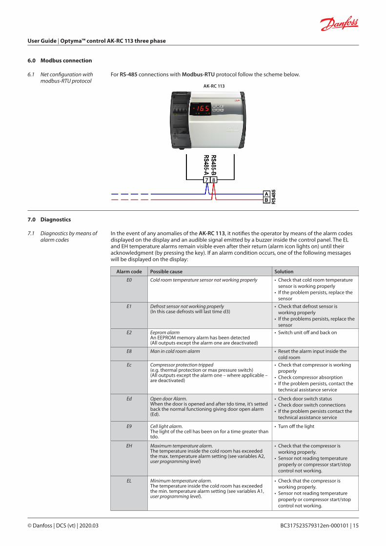
6.1 Net configuration with modbus-RTU protocol
6.0 Modbus connection
For RS-485 connections with Modbus-RTU protocol follow the scheme below.
AK-RC 113
7 8
7.1 Diagnostics by means of alarm codes
7.0 Diagnostics
In the event of any anomalies of the AK-RC 113, it notifies the operator by means of the alarm codes displayed on the display and an audible signal emitted by a buzzer inside the control panel. The EL and EH temperature alarms remain visible even after their return (alarm icon lights on) until their acknowledgment (by pressing the key). If an alarm condition occurs, one of the following messages will be displayed on the display:
Alarm code Possible cause Solution
E0 Cold room temperature sensor not working properly • Check that cold room temperature sensor is working properly
• If the problem persists, replace the sensor
E1 Defrost sensor not working properly(In this case defrosts will last time d3)
• Check that defrost sensor is working properly
• If the problems persists, replace the sensor
E2 Eeprom alarmAn EEPROM memory alarm has been detected(All outputs except the alarm one are deactivated)
• Switch unit off and back on
E8 Man in cold room alarm • Reset the alarm input inside the cold room
Ec Compressor protection tripped(e.g. thermal protection or max pressure switch)(All outputs except the alarm one – where applicable – are deactivated)
• Check that compressor is working properly
• Check compressor absorption• If the problem persists, contact the
technical assistance service
Ed Open door Alarm.When the door is opened and after tdo time, it’s setted back the normal functioning giving door open alarm (Ed).
• Check door switch status • Check door switch connections• If the problem persists contact the
technical assistance service
E9 Cell light alarm.The light of the cell has been on for a time greater than tdo.
• Turn off the light
EH Maximum temperature alarm.The temperature inside the cold room has exceeded the max. temperature alarm setting (see variables A2, user programming level)
• Check that the compressor is working properly.
• Sensor not reading temperature properly or compressor start/stop control not working.
EL Minimum temperature alarm.The temperature inside the cold room has exceeded the min. temperature alarm setting (see variables A1, user programming level).
• Check that the compressor is working properly.
• Sensor not reading temperature properly or compressor start/stop control not working.

User Guide | Optyma™ control AK-RC 113 three phase
16 | BC317523579312en-000101 © Danfoss | DCS (vt) | 2020.03
7.2 Troubleshooting If there is not an alarm code, we list below some of the most common causes that can cause anomalies. These causes can be due to problems internal or external to the electrical panel.
Event Possible cause Operation to be performed
The compressordoesn’t start
Display is OFF
Absence of power supply.
• Check that the display on the panel and the plant in operation green light are on.
• Check the connections of the ambient probe.• If the problem persists replace the sensor.
Intervention of the general protection circuit breaker.
• Before reinserting the circuit breaker, check that there are no short circuits. Then reinsert the circuit breaker checking all the absorptions to identify any anomalies.
Intervention of the circuit breakerof the auxiliary circuits.
• Before reinserting the circuit breaker, check that there are no short circuits. Then reinsert the circuit breaker checking all the absorptions to identify any anomalies.
Intervention of the secondary circuit protection fuse on the transformer.
• Restore the fuse (Glass fuse 10x20 F250mA 250V).• Check that the absorption on the econdary of the
transformer does not exceed 0.25A.• Check that no other users have been connected to
the Kriwan power supply terminals.• Check that there are no short circuits on the
secondary circuit.
The compressordoesn’t start
The panel is in stand-by.• Verify that the panel is not in standby mode (flashing
green light). In this case, press the key to reactivate the panel (green light on steady).
Intervention or anomaly ofpressure switches or kriwan.
• Check the electrical connections, the calibrations and the correct functioning of the sensors and the compressor.
• If it is the first ignition, check the presence of the "PumpDown / Thermostat" operating mode selection bridge on terminal board X1 and jumper the consent terminals of the devices not present in the system (Pressure Switches, Kriwan)
The defrost cycle is not performed
Incorrect setting of the parameters relating to the defrost cycle
• Check the correct entry of the parameters.
User Guide | Optyma™ control AK-RC 113 three phase
© Danfoss | DCS (vt) | 2020.03 BC317523579312en-000101 | 17
8.1 General safety rules
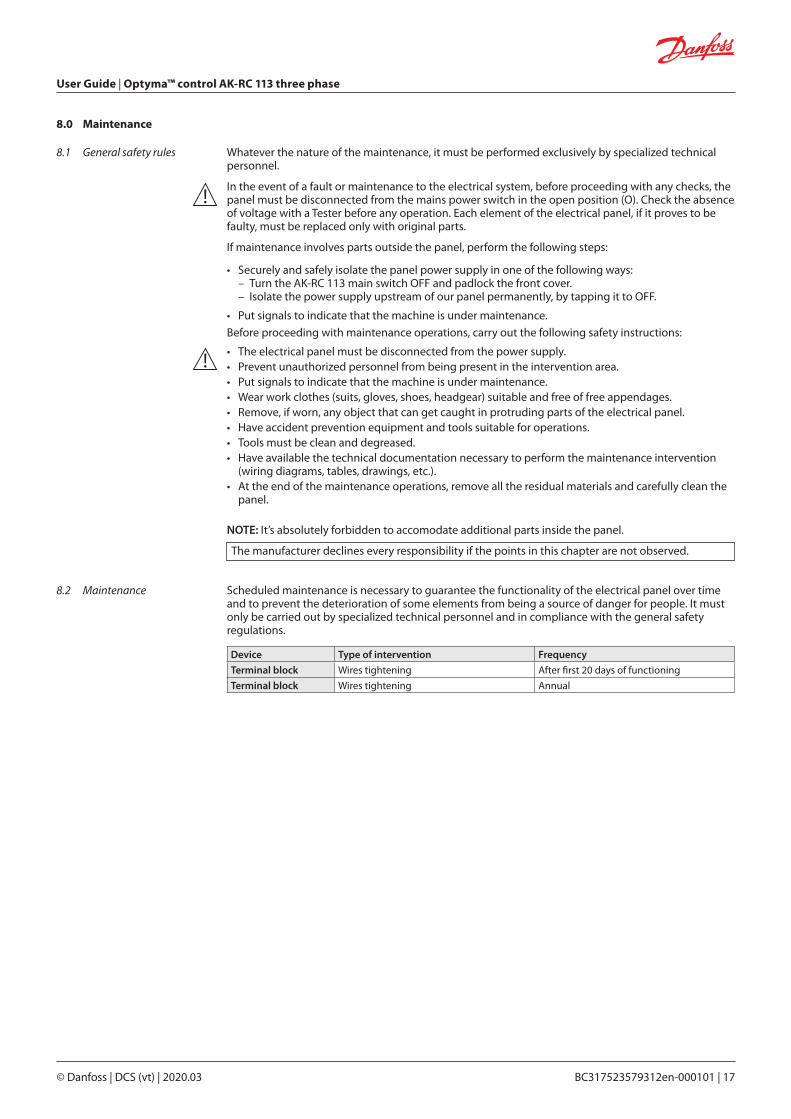
8.0 Maintenance
Whatever the nature of the maintenance, it must be performed exclusively by specialized technical personnel.
In the event of a fault or maintenance to the electrical system, before proceeding with any checks, the panel must be disconnected from the mains power switch in the open position (O). Check the absence of voltage with a Tester before any operation. Each element of the electrical panel, if it proves to be faulty, must be replaced only with original parts.
If maintenance involves parts outside the panel, perform the following steps:
• Securely and safely isolate the panel power supply in one of the following ways: – Turn the AK-RC 113 main switch OFF and padlock the front cover. – Isolate the power supply upstream of our panel permanently, by tapping it to OFF.
• Put signals to indicate that the machine is under maintenance.
Before proceeding with maintenance operations, carry out the following safety instructions:
• The electrical panel must be disconnected from the power supply.• Prevent unauthorized personnel from being present in the intervention area.• Put signals to indicate that the machine is under maintenance.• Wear work clothes (suits, gloves, shoes, headgear) suitable and free of free appendages.• Remove, if worn, any object that can get caught in protruding parts of the electrical panel.• Have accident prevention equipment and tools suitable for operations.• Tools must be clean and degreased.• Have available the technical documentation necessary to perform the maintenance intervention
(wiring diagrams, tables, drawings, etc.).• At the end of the maintenance operations, remove all the residual materials and carefully clean the
panel.
NOTE: It’s absolutely forbidden to accomodate additional parts inside the panel.
The manufacturer declines every responsibility if the points in this chapter are not observed.
8.2 Maintenance Scheduled maintenance is necessary to guarantee the functionality of the electrical panel over time and to prevent the deterioration of some elements from being a source of danger for people. It must only be carried out by specialized technical personnel and in compliance with the general safety regulations.
Device Type of intervention Frequency
Terminal block Wires tightening After first 20 days of functioning
Terminal block Wires tightening Annual
User Guide | Optyma™ control AK-RC 113 three phase
18 | BC317523579312en-000101 © Danfoss | DCS (vt) | 2020.03
9.0 Appendices
9.1 AK-RC 113 wiring diagram
1 2 3 4 5 6 7 8 9 10 11 12 13 14 15 16 17 20 21 18 19
JB01.1
1 2 3 13 14 15
JB01.2
JB01.3
JB01.13
JB01.14
JB01.15
JB01.5
5
JB01.6
6
JB01.7
7JB01.8
L8
JB01.4
4
JB01.9
9
JB01.10
L10
JB01.11
L11
1 2 3 4 5 6 7 8 9 10 11 12 13 14 15 16 17 20 21 18 19JB01.1
1 2 3 13 14 15
JB01.2
JB01.3
JB01.13
JB01.14
JB01.15
JB01.5
5
JB01.6
6
JB01.7
7
JB01.8
8
JB01.4
4
JB01.9
9
JB01.10
L10
JB01.11
L11
OPTYMA™ Control, three phase (4 HP)
OPTYMA™ Control, three phase (7.5 HP)M
OD
BUS B-
PowerSupply
230 V AC Defrost Fans Compr. Aux1/All.
Condensingunit
Electricswitchboard
enable
Aux2 Light
MO
DBU
S A+
Defrost p
robe
Am
bient p
robe
Com
mon p
robes
Com
mon dig. inp
utsD
oor switch
Com
p. protection
MO
DBU
S B-
PowerSupply
230 V AC Defrost Fans Compr. Aux1/All.
Condensingunit
Electricswitchboard
enable
Aux2 Light
MO
DBU
S A+
Defrost p
robe
Am
bient p
robe
Com
mon p
robes
Com
mon dig. inp
utsD
oor switch
Com
p. protection

User Guide | Optyma™ control AK-RC 113 three phase
© Danfoss | DCS (vt) | 2020.03 BC317523579312en-000101 | 19
9.2 Part List
Key
Ref. Description
1. Box rear in Abs
2. 4 poles magnetothermic circuit breaker with general switch / general protection function
3. Contactors for units control
4. Compressor protection motor circuit breaker
5. Auxiliary protection 1-pole magnetothermic circuit breaker
6. Box front opening hinges
7. Front cover in transparent polycarbonate
8. Transparent polycarbonate screw cover
9. Auxiliary circuits transformer (N.B. with inside a glass fuse 10 x 20 F250 mA 250 V)
10. Connector for linking panel and the electronic card
11. Front panel
12. Electronic card
13. Electronic card cover
14. Electronic card fixing screws
15. Box closure screws
16. Auxiliary terminal block X1
17. Power terminal block X2
10.0 Ordering Type Code No.
Optyma Control, three phase (4HP), including 2 sensors, 4.5 – 6.3 A 080Z3221
Optyma Control, three phase (4HP), including 2 sensors, 7 – 10 A 080Z3222
Optyma Control, three phase, (7.5HP), including 2 sensors, 11 – 16 A 080Z3226
Optyma Control, three phase, (7.5HP), including 2 sensors, 14 – 20 A 080Z3227
Sensor EKS 221 (spare part) 084N3210

Danfoss can accept no responsibility for possible errors in catalogues, brochures and other printed material. Danfoss reserves the right to alter its products without notice. This also applies to products already on order provided that such alterations can be made without subsequential changes being necessary eady agreed.All trademarks in this material are property of the respective companies. Danfoss and the Danfoss logotype are trademarks of Danfoss A/S. All rights reserved.
© Danfoss | DCS (vt) | 2020.03 BC317523579312en-000101 | 20