Opto & Power Board (OPB)
14
Martin van Beuzekom, Jan Buytaert, Lars Eklund Opto & Power Board (OPB) Summary of the functionality of the opto & power board
-
Upload
ifeoma-young -
Category
Documents
-
view
45 -
download
3
description
Opto & Power Board (OPB). Summary of the functionality of the opto & power board. Electronics overview. off-detector electronics (remote). < 1 m. 2 x front-end hybrids. 1 x opto & power board. One OPB serves one module = 2 hybrids. v acuum f eed-through. 6 data links. 3 x VTRx. - PowerPoint PPT Presentation
Transcript of Opto & Power Board (OPB)

Martin van Beuzekom, Jan Buytaert, Lars Eklund
Opto & Power Board (OPB)
Summary of the functionality of the opto & power board
L. Eklund, VELO upgrade electronics review 2
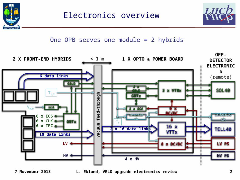
Electronics overview
va
cu
um
fe
ed
-th
rou
gh
HV PS
LV PS
6 data links
10 data links
GBTx6 x ECS6 x CLK6 x TFC
LV
T1,2
HV
2 X FRONT-END HYBRIDS
TELL40
8 x DC/DC
16 x VTTx
3 x VTRxGBTx
2 x GBLD
6 x DC/DC2 x SCA
2 x 16 data links
1 X OPTO & POWER BOARD
SOL40
OFF-DETECTOR ELECTRONI
CS(remote)
GBLD
Interlock
SCAVMON
< 1 m
Interlock
4 x HV
T3
7 November 2013
One OPB serves one module = 2 hybrids
L. Eklund, VELO upgrade electronics review 3
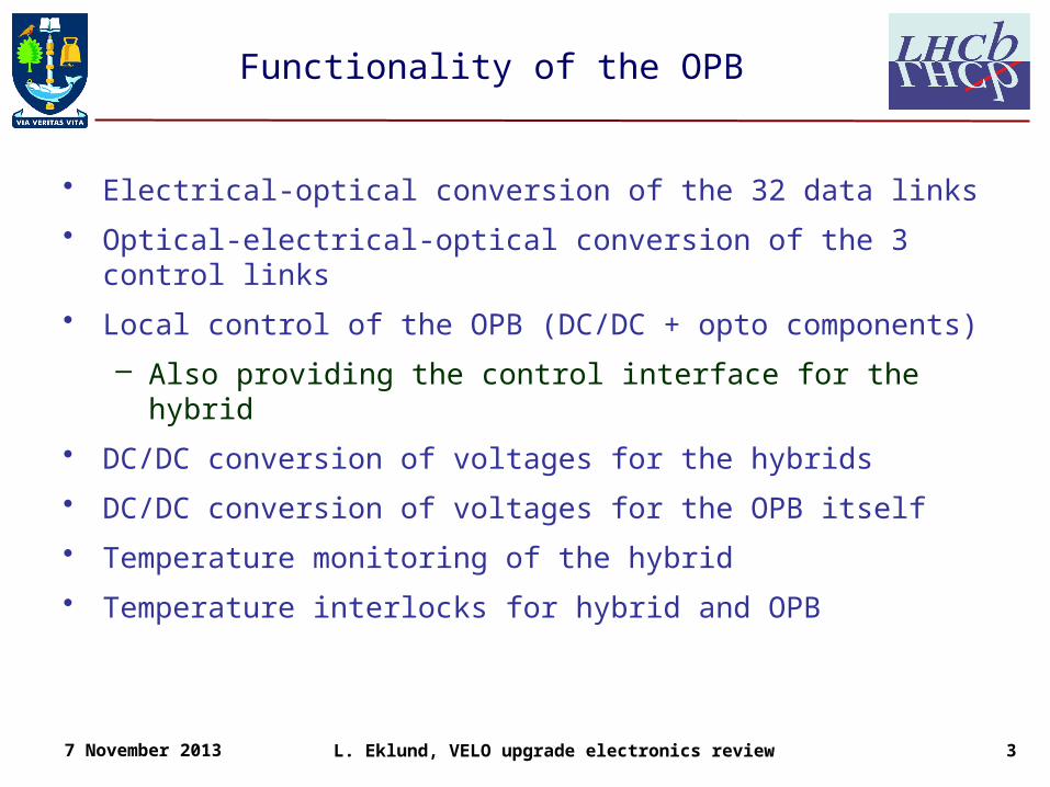
Functionality of the OPB
• Electrical-optical conversion of the 32 data links
• Optical-electrical-optical conversion of the 3 control links
• Local control of the OPB (DC/DC + opto components)
– Also providing the control interface for the hybrid
• DC/DC conversion of voltages for the hybrids
• DC/DC conversion of voltages for the OPB itself
• Temperature monitoring of the hybrid
• Temperature interlocks for hybrid and OPB
7 November 2013

L. Eklund, VELO upgrade electronics review 4
Electrical-optical conversion of data links
• Will use 16 VTTx modules, mounted as mezzanines– Edge connector brings signals from motherboard
• Supply voltage: 2.5 V, 300-400 mA• Control: I2C bus with 2 devices + enable signal• Radiation qualification (according to spec)
– 500 kGy, 5x10¹⁵ neq/cm2
• Questions– Is metal housing a possibility?– How is the heat removed?
7 November 2013

L. Eklund, VELO upgrade electronics review 5
Opto-electrical conversion of control links
• Will use 3 VTRx modules, mounted as mezzanines– Edge connector brings signals from motherboard
• Supply voltage: 2.5 V, 200-250 mA• Control: I2C bus with 1 device + enable signal• Radiation qualification (according to spec)
– 500 kGy, 5x10¹⁵ neq/cm2
• Questions– Is metal housing a possibility?– How is the heat removed?
7 November 2013

L. Eklund, VELO upgrade electronics review 6
Control and configuration
• Each OPB has 3 bi-directional optical control links– 1 for each hybrid plus 1 for local control
• Control and configuration of the hybrid– 1 GBTx and 1 SCA mounted on each hybrid, providing
• 6 clocks• 6 or 12 e-links for configuration• 6 e-links for TFC commands• SCA used for voltage and DAC output monitoring
– 1 High-speed electrical control link per hybrid and per direction– GBLD ASICs drive the electrical links
• 1 on each hybrid, 2 on the OPB
• Control and configuration of the OPB– The OPB has one GBTx and two SCA for local control
7 November 2013
L. Eklund, VELO upgrade electronics review 7
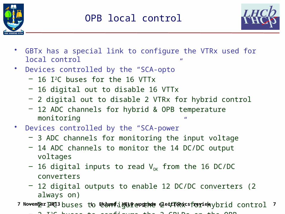
OPB local control
• GBTx has a special link to configure the VTRx used for local control• Devices controlled by the “SCA-opto”
– 16 I2C buses for the 16 VTTx– 16 digital out to disable 16 VTTx– 2 digital out to disable 2 VTRx for hybrid control– 12 ADC channels for hybrid & OPB temperature monitoring
• Devices controlled by the “SCA-power”– 3 ADC channels for monitoring the input voltage– 14 ADC channels to monitor the 14 DC/DC output voltages– 16 digital inputs to read VOK from the 16 DC/DC converters– 12 digital outputs to enable 12 DC/DC converters (2 always on)– 2 I2C buses to configure the 2 VTRx for hybrid control– 2 I2C buses to configure the 2 GBLDs on the OPB
7 November 2013

L. Eklund, VELO upgrade electronics review 8
DC/DC for the hybrid - VeloPix
• Will use the rad-hard DC/DC modules– Tested to 5x10¹³ p/cm2 @ PSI and 547 MRad with x-rays
• VeloPix power requirements– V = 1.5 V, Idigital < 1 A and Ianalogue < 1 A per VeloPix– One sensor tile (3 VeloPix) share 1 analogue and 1 digital supply
provided by 2 DC/DC converters– 4 DC/DC converters & 1 primary power supply channel (~5 V) per
hybrid• Load on the DC/DC converter (75% efficiency)
– DC/DC conversion factor: 5 V/1.5 V = 3.3– 3 A @ 1.5 V output => 1.2 A @ 5 V input
• 2 hybrids & 2 PS channels per OPB– 2 x 4.8 A @ 5 V input
• Head dissipation– 36 W on the hybrid– 12 W on the OPB
7 November 2013

L. Eklund, VELO upgrade electronics review 9
DC/DC for the hybrid – support electronics
• Support electronics power requirements– GBTx: 1.5 V, 1 A ?– SCA: 1.5 V, 300 mA ?– GBLD: 2.5 V (1.5 V possible?), 150 mA?
• Total estimated power– 1.3 A @ 1.5 V and 0.3 A @ 2.5 V– 1.6 A @ 1.5 V (if GBLD can be powered with 1.5 V)
• Supplied by rad-hard DC/DC converters– GBTx powered from the digital supply of the ‘far’ pixel tile
• SCA from the ‘near’ tile digital supply?• Digital consumption depend on occupancy
– Separate supply, both 1.5 and 2.5 V?• Control signals
– Enable (input), power good (output)
7 November 2013

L. Eklund, VELO upgrade electronics review 10
DC/DC for the OPB
• 16 VTTx powered by 2 DC/DC converters (75% efficient)– 8 x 400 mA @ 2.5 V per DC/DC– Input 2.1 A @ 5 V
• 1 always enabled 2.5 V DC/DC (75% efficient)– 3 VTRx consuming 3 x 300 mA– 2 GBLD consuming 2 x 150 mA– 1.2 A @ 2.5 V => 800 mA @ 5 V
• 1 always enabled 1.5 V DC/DC (75% efficient)– 2 SCA consuming 2 x 300 mA– 1 GBTx consuming 1 A– 1.6 A @ 1.5 V => 650 mA @ 5 V
• Total: 4 DC/DC converters– One 5 V power supply channel with 3.6 A– 18 W dissipated on the OPB
7 November 2013

L. Eklund, VELO upgrade electronics review 11
Temperature monitoring & interlock
• 2 thermistors on each hybrid and 2 on the OPB– Connected with voltage divider located on the OPB
• Measured with two ADC channels– Vin and Vtemp
• H/W interlock circuit comparing voltages Vthres & Vtemp
– Rinterlock sets the shooting point• DC/DC converters are enabled by local AND between
enable from SCA and the interlock signal– Interlock signal sent off-detector as well
• Interlock signals collected by the Interlock Box– From all OPBs, vacuum, cooling and from beam
conditions.– Enables LV and HV power supplies– Provides monitoring of the interlock states
7 November 2013
Rin
terlo
ck
Rth
erm
ist
or
Rre
f
Rre
f
Vthresh Vtemp
Vin
L. Eklund, VELO upgrade electronics review 12
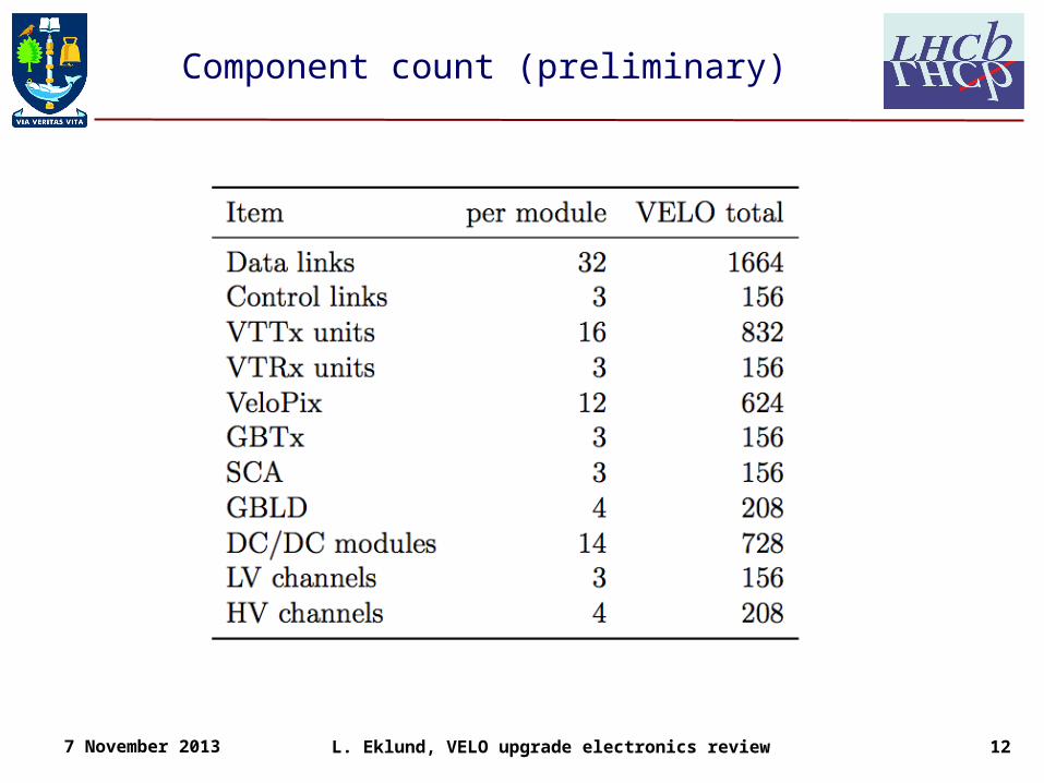
Component count (preliminary)
7 November 2013

L. Eklund, VELO upgrade electronics review 13
Cartoon layout (first guess)
7 November 2013
~350 mm
3 VTTx5 VTTx3 VTTx 3 VTRx
GB
T
components
+ interlock
5 VTTx
DC
/DC
DC
/DC
DC
/DC
DC
/DC
DC
/DC
DC
/DC
DC
/DC
connectors to vacuum feed-through
optical fibre connectors Power dissipation 30-35 W per board
cool
ing
bars
~10
0 m
m

L. Eklund, VELO upgrade electronics review 14
Summary
• The Opto & Power Board (OPB) provides the electrical interface to the front-end module
• It fulfils the following purposes– Opto-electrical conversion of data & control– DC/DC conversion of supply voltages– Local control and monitoring– Temperature monitoring & interlock
• It can be build almost completely with versatile link and DC/DC project components– Only COTS components on in the interlock circuit
• Functionality fits on one PCB– But active cooling will be required
7 November 2013